available online at sciencedirect - core · in the clinch river breeder reactor project, the dbes...
TRANSCRIPT

eDirect
Nu c l e a r E n g i n e e r i n g a n d T e c h n o l o g y 4 8 ( 2 0 1 6 ) 9 5 2e9 6 4
Available online at Scienc
Nuclear Engineering and Technology
journal homepage: www.elsevier .com/locate /net
Original Article
Evaluation of a SodiumeWater Reaction EventCaused by Steam Generator Tubes Break in thePrototype Generation IV Sodium-cooled FastReactor
Sang June Ahn*, Kwi-Seok Ha, Won-Pyo Chang, Seok Hun Kang,Kwi Lim Lee, Chi-Woong Choi, Seung Won Lee, Jin Yoo, Jae-Ho Jeong, andTaekyeong Jeong
Korea Atomic Energy Research Institute (KAERI), 1045 Daedeokdaero, Yuseong, Daejeon 305-353, Republic of Korea
a r t i c l e i n f o
Article history:
Received 23 May 2015
Received in revised form
3 January 2016
Accepted 10 February 2016
Available online 18 March 2016
Keywords:
Multidimensional Analysis of
Reactor Safety-Liquid Metal
Reactor
Prototype Generation IV Sodium-
Cooled Fast Reactor
SodiumeWater Advanced Anal-
ysis Method-II
SodiumeWater Reaction
* Corresponding author.E-mail address: [email protected] (S.J.
http://dx.doi.org/10.1016/j.net.2016.02.0161738-5733/Copyright © 2016, Published by Elthe CC BY-NC-ND license (http://creativecom
a b s t r a c t
The prototype generation IV sodium-cooled fast reactor (PGSFR) has been developed by the
Korea Atomic Energy Research Institute. This reactor uses sodium as a reactor coolant to
transfer the core heat energy to the turbine. Sodium has chemical characteristics that
allow it to violently react with materials such as a water or steam. When a sodiumewater
reaction (SWR) occurs due to leakage or breakage of steam generator tubes, high-pressure
waves and corrosive reaction products are produced, which threaten the structural
integrity of the components of the intermediate heat-transfer system (IHTS) and the safety
of the primary heat-transfer system (PHTS). In the PGSFR, SWR events are included in the
design-basis event. This event should be analyzed from the viewpoint of the integrities of
the IHTS and fuel rods. To evaluate the integrity of the IHTS based on the consequences of
the SWR, the behaviors of the generated high-pressure waves are analyzed at the major
positions of a failed IHTS loop using a sodiumewater advanced analysis method-II code.
The integrity of the fuel rods must be consistently maintained below the safety acceptance
criteria to avoid the consequences of the SWR. The integrity of the PHTS is evaluated using
the multidimensional analysis of reactor safety-liquid metal reactor code to model the
whole plant.
Copyright © 2016, Published by Elsevier Korea LLC on behalf of Korean Nuclear Society. This
is an open access article under the CC BY-NC-ND license (http://creativecommons.org/
licenses/by-nc-nd/4.0/).
Ahn).
sevier Korea LLC on behalf of Korean Nuclear Society. This is an open access article undermons.org/licenses/by-nc-nd/4.0/).

Nu c l e a r E n g i n e e r i n g a n d T e c h n o l o g y 4 8 ( 2 0 1 6 ) 9 5 2e9 6 4 953
1. Introduction
The prototype generation IV sodium-cooled fast reactor
(PGSFR) has been developed by the Korea Atomic Energy
Research Institute. It has a pool-type configuration and uses
sodiumas a reactor coolant. The reactor is designed to have the
capability to produce 150MWe of electric power. It is composed
of primary heat-transfer system (PHTS), intermediate heat-
transfer system (IHTS), decay heat removal system (DHRS),
and secondary system including the steam generator (SG).
Fig. 1 shows the overall configuration of the PGSFR. The core
heat energy is transferred to IHTS sodium through the four in-
termediate heat exchangers (IHXs) tubes,which are submerged
in the cold pool of the reactor vessel. To protect the PHTS in the
event of a sodiumewater reaction (SWR), the sodium of the
closed-loop type IHTS is circulated between the PHTS and SG
during normal operation. The high-temperature sodium
escaping fromthe IHX tube is transported to theSGshell,which
subsequently transfers its heat to the subcooled water flowing
into the SG tubes. Thus, the cooled sodium is eventually
transported to the IHX tube by the IHTS pump. The subcooled
water supplied by the feed water pump passes through the SG
tubes having a vertical single-wall type. It is then transformed
into superheated steam by the heat transferred from the hot
sodium of the SG shell and is transported to the turbine. The
DHRS is operated to remove the residual heat from the core and
sensible heat from the PHTS through the four decay heat ex-
changers (DHXs)submerged inthehotpoolof thereactorvessel.
It is composed of two loops of passive DHRS (PDHRS) operated
with natural circulation flow and two loops of active DHRS
Fig. 1 e Configuration of the prototype generation IV sodium-co
exchanger; DHRS, decay heat removal system; FHX, forced-draf
transfer system; SWRPRS, sodiumewater reactor pressure relie
(ADHRS) operated with forced circulation flow by an electro-
magnetic pump. Each train is designed to be capable of
removing 50% of the total DHRS heat.
Because of the high pressure difference between the inner
and outer parts of the SG tube, a large load is applied to the SG
tube surface. The sodium of the SG shell side has chemical
characteristics that allow it to react with materials such as
water, steam, and oxygen. If an SWR event occurs due to SG
tubes leak or break, high-pressure waves and corrosive reac-
tion products are instantaneously generated and propagated
to the IHTS components through the IHTS pipes. This event
threatens the safety of the reactor and integrity of the IHTS
components including the SG tubes. For this reason, an SWR
event has been generally considered as one of the design-
basis events (DBEs) in sodium-cooled fast reactors.
An SWR is a violent exothermic reaction similar to a simple
combustion process [1]. The SWR also generates hydrogen gas
that may result in a pressure increase in the system, poten-
tially causing an explosion. Table 1 presents the generally
accepted classification of water/steam leaks and dominant
damage and threat [2]. The possible causes of an SG tube leak
are as follows [3]:
� Micro leaks (<0.1 g/s): A micro leak is often developed from
an interangular crack in a defectedweld and a fatigue crack
in a tube wall. The corrosive reaction products often
remain in place and plug the leak. The leak may stay
plugged for several days or weeks.
� Small leaks (1e10 g/s): A small leak often causes localized
tube damage, a phenomenon called “self-wastage.” The
oled fast reactor. AHX, natural-draft sodium-to-air heat
t sodium-to-air heat exchanger; IHTS, intermediate heat-
f system.

Table 1 e Classification of water/steam leaks into sodiumin a steam generator.
Leak class Leak rate(g/sec)
Dominant threat
Micro <0.1 Too small to detect
Reaction products form slowly,
bubbling may occur
No threat to other adjacent tubes
Small 1.0e10 Generate a corrosive sodiumewater jet
Damage adjacent tubes: Impingement
wastage
Intermediate 10e2,000 Lower end: Damage adjacent tubes
by wastage
Higher end: Tube failure by overheating
and pressurization due to hydrogen
production (single tube)
Large >2,000 Rapid pressurization due to hydrogen
production (multiple tubes)
Tube failure by overheating
and overpressure
Nu c l e a r E n g i n e e r i n g a n d T e c h n o l o g y 4 8 ( 2 0 1 6 ) 9 5 2e9 6 4954
leak grows by a combination of corrosion and erosion. A
small leak can also cause damage to adjacent steam tubes,
a phenomenon termed as “impingementwastage.”Awater
jet from a small leak forms a turbulent flow under sodium
“flame.”
� Intermediate leaks (10e2,000 g/s): When the leak rate rises
into the intermediate range, the reaction flame becomes
large and affects many other tubes. The flame interacts
with the flowing sodium and triggers a chaotic turbulent
interaction region characterized by widely fluctuating
temperatures.
� Large leaks (>2,000 g/s): A large leak may cause a rapid in-
crease in pressure in the SG due to a large amount of
hydrogen gas generated from SWR. It may cause explosion
and damage the components of the secondary cooling
circuits.
Based on the classification of the leak rate, twomethods to
cope with the SWR events are applied to the system design of
the PGSFR. For micro-, small-, and intermediate-size leaks,
components such as a hydrogen gas detector and acoustic
noise sensor are designed to detect the sodium leaks on the
surface of SG tubes. For a large-size leak event, a rupture disk
as a safety grade and sodiumewater reactor pressure relief
system (SWRPRS) are designed to mitigate the event and
prevent the sequential secondary SWR. In addition, the leak-
before-break (LBB) principle is applied to the system design
of the pipes and components including the sodium in the
PGSFR. The concept of the LBB is applied for large-diameter,
high-quality piping systems as a means of enhancing the
safety of nuclear power plants [4].
With regard to the PHTS safety, the SWR due to the SG
tubes leak or break is categorized as a loss of core cooling
capability event. In the PGSFR, the tentatively determined
DBEs in relation to the SWR are as follows: (1) events caused by
micro or small leaks on the SG tube surface. Here, the “leak
rate” is defined as the rate within the range capable of being
detected by the sodium leak detection system; (2) events
caused by an intermediate or single SG tube double-ended
guillotine break (DEGB). Based on the growth and
development of leak, the original leak area could be larger, but
is not expected to approach that of a double-ended guillotine
[5]; (3) events caused by five simultaneous SG tubes DEGB
events as large leak DBEs. In the Clinch River Breeder Reactor
Project, the DBEs for large leak rate events were defined as a
DEGB failure of one SG tube followed by six additional DEGB
tube failures with a time lag of 0.1 seconds [6]. In Monju, it is
defined as an instantaneous one tube DEGB followed by failure
of three tubes as secondary failures [7]. In prototype fast
breeder reactors, it is defined as an instantaneous DEGB fail-
ure of three tubes at the top of the SG [8].
Based on the process of leak growth and occurrence fre-
quency of the event, simultaneous single or more SG tubes
DEGB events have been regarded as being “extremely un-
likely.” Therefore, the five simultaneous SG tubes DEGB events
as large leak DBEs are a very conservative assumption. In
addition, because of mitigations such as the operation of the
SWRPRS and depressurization in the failed IHTS loop after a
rupture disk burst, the consequences following the secondary
SWRwith a time lag have little influence on the integrity of the
IHTS and PHTS.
In the PGSFR, the safety evaluation of the SWR is per-
formed according to the aforementioned classifications. The
first evaluation is applied to an event caused by a small leak
rate relatively lower than a single SG tube DEGB. If this event
occurs, the leaks are detected by the leak detection system
and alerted to the operator by an alarm. The operator then
manually shuts down the reactor and repairs the failed
tubes. A second evaluation is applied to the large leak rate
event caused simultaneous one or more SG tubes DEGB. The
initial high-pressure waves are propagated to the IHX tube
through the IHTS loop pipes in a millisecond order. Upon
reaching the burst pressure of a rupture disk, the sodium of
the affected IHTS loop is immediately discharged to the so-
dium dump tank (SDT). Once a rupture disk bursts, the
reactor protection system (RPS) signal is produced. To pro-
hibit the subsequent secondary SWR by the continuous
release of water or steam through the failed SG tubes, the
isolation valves separately connected to the feed water and
steam lines of the SG are automatically closed by SWRPRS.
For large leak rate SWRDBEs, the structural boundaries of the
affected IHTS and SG can be protected from the high-
pressure waves produced following a secondary SWR by
shutting down the reactor, thereby retaining its integrity.
In this paper, we evaluated the integrity of IHTS and
reactor for a large leak rate SWR DBE using the sodiumewater
advanced analysis method-II (SWAAM-II) code, which is
capable of modeling the SWR phenomena, and multidimen-
sional analysis of reactor safety-liquid metal reactor (MARS-
LMR), which is capable of modeling the behaviors of the PHTS.
2. Preliminary evaluation of the IHTSintegrity
2.1. Analysis methods and SWAAM-II input modeling
To evaluate the integrity of the IHTS in the event of a large leak
SWR, the SWAAM-II [9] code, which was developed in the
Argonne National Laboratory, was used. SWAAM-II is
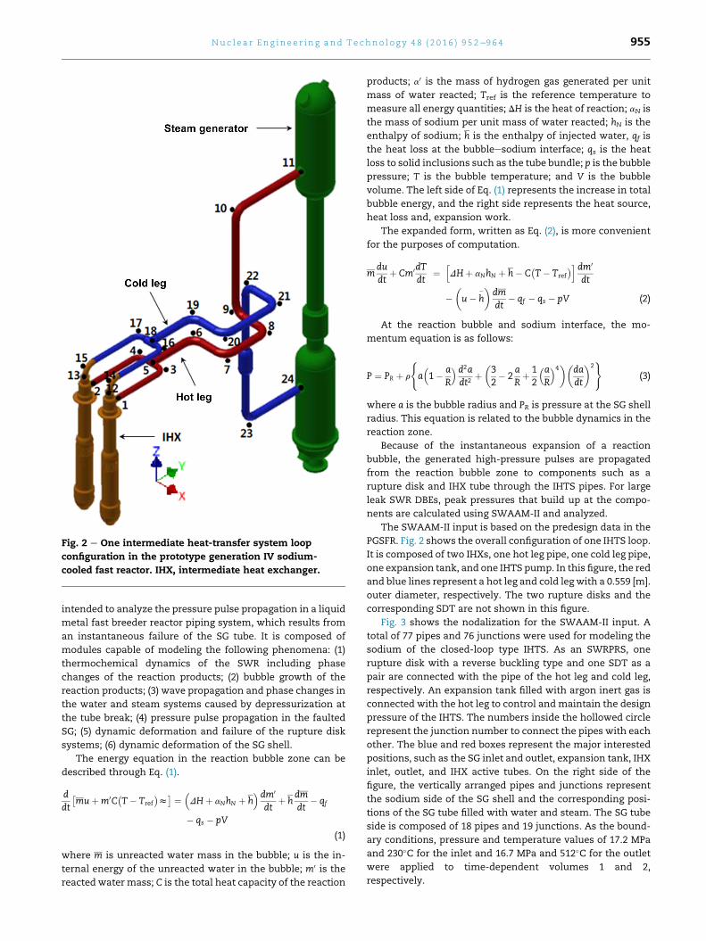
Fig. 2 e One intermediate heat-transfer system loop
configuration in the prototype generation IV sodium-
cooled fast reactor. IHX, intermediate heat exchanger.
Nu c l e a r E n g i n e e r i n g a n d T e c h n o l o g y 4 8 ( 2 0 1 6 ) 9 5 2e9 6 4 955
intended to analyze the pressure pulse propagation in a liquid
metal fast breeder reactor piping system, which results from
an instantaneous failure of the SG tube. It is composed of
modules capable of modeling the following phenomena: (1)
thermochemical dynamics of the SWR including phase
changes of the reaction products; (2) bubble growth of the
reaction products; (3) wave propagation and phase changes in
the water and steam systems caused by depressurization at
the tube break; (4) pressure pulse propagation in the faulted
SG; (5) dynamic deformation and failure of the rupture disk
systems; (6) dynamic deformation of the SG shell.
The energy equation in the reaction bubble zone can be
described through Eq. (1).
ddt
�muþm0C
�T� Tref
�z� ¼ �
DHþ aNhN þ h� dm0
dtþ h
dmdt
� qf
� qs � pV
(1)
where m is unreacted water mass in the bubble; u is the in-
ternal energy of the unreacted water in the bubble; m0 is the
reacted water mass; C is the total heat capacity of the reaction
products; a0 is the mass of hydrogen gas generated per unit
mass of water reacted; Tref is the reference temperature to
measure all energy quantities; DH is the heat of reaction; aN is
the mass of sodium per unit mass of water reacted; hN is the
enthalpy of sodium; h is the enthalpy of injected water, qf is
the heat loss at the bubbleesodium interface; qs is the heat
loss to solid inclusions such as the tube bundle; p is the bubble
pressure; T is the bubble temperature; and V is the bubble
volume. The left side of Eq. (1) represents the increase in total
bubble energy, and the right side represents the heat source,
heat loss and, expansion work.
The expanded form, written as Eq. (2), is more convenient
for the purposes of computation.
mdudt
þ Cm0dTdt
¼hDHþ aNhN þ h� C
�T� Tref
�idm0
dt
��u� h
� dmdt
� qf � qs � pV (2)
At the reaction bubble and sodium interface, the mo-
mentum equation is as follows:
P ¼ PR þ r
(a�1� a
R
� d2adt2
þ�32� 2
aRþ 12
�aR
�4�
dadt
2)
(3)
where a is the bubble radius and PR is pressure at the SG shell
radius. This equation is related to the bubble dynamics in the
reaction zone.
Because of the instantaneous expansion of a reaction
bubble, the generated high-pressure pulses are propagated
from the reaction bubble zone to components such as a
rupture disk and IHX tube through the IHTS pipes. For large
leak SWR DBEs, peak pressures that build up at the compo-
nents are calculated using SWAAM-II and analyzed.
The SWAAM-II input is based on the predesign data in the
PGSFR. Fig. 2 shows the overall configuration of one IHTS loop.
It is composed of two IHXs, one hot leg pipe, one cold leg pipe,
one expansion tank, and one IHTS pump. In this figure, the red
and blue lines represent a hot leg and cold leg with a 0.559 [m].
outer diameter, respectively. The two rupture disks and the
corresponding SDT are not shown in this figure.
Fig. 3 shows the nodalization for the SWAAM-II input. A
total of 77 pipes and 76 junctions were used for modeling the
sodium of the closed-loop type IHTS. As an SWRPRS, one
rupture disk with a reverse buckling type and one SDT as a
pair are connected with the pipe of the hot leg and cold leg,
respectively. An expansion tank filled with argon inert gas is
connected with the hot leg to control and maintain the design
pressure of the IHTS. The numbers inside the hollowed circle
represent the junction number to connect the pipes with each
other. The blue and red boxes represent the major interested
positions, such as the SG inlet and outlet, expansion tank, IHX
inlet, outlet, and IHX active tubes. On the right side of the
figure, the vertically arranged pipes and junctions represent
the sodium side of the SG shell and the corresponding posi-
tions of the SG tube filled with water and steam. The SG tube
side is composed of 18 pipes and 19 junctions. As the bound-
ary conditions, pressure and temperature values of 17.2 MPa
and 230�C for the inlet and 16.7 MPa and 512�C for the outlet
were applied to time-dependent volumes 1 and 2,
respectively.

Fig. 3 e Nodalizationfor sodiumewater advanced analysis method-II input. B.C., Boundary Condition; IHX, intermediate
heat exchanger; SG, steam generator.
Nu c l e a r E n g i n e e r i n g a n d T e c h n o l o g y 4 8 ( 2 0 1 6 ) 9 5 2e9 6 4956
2.2. Evaluation results and discussion
Prior to calculating large leak SWR DBEs, the peak pressure at
the break positions of the SG tube is determined and then
analyzed for multiple SG tubes DEGB. The following condi-
tions and assumptions were applied: the burst pressure of the
rupture disk is set to 1.0 MPa and a single SG tube DEGB is
assumed.

0 20 40 60 80 1000.0
0.5
1.0
1.5
2.0
2.5
3.0
3.5
Pre
ssur
e at
SG
tube
bre
ak p
oint
s (M
Pa)
Time (ms)
Top break point 533 Mid break point 525 Bot break point 517
Fig. 4 e Pressures histories at the steam generator tube
break points (1 double-ended guillotine break, rupture disk
burst pressure ¼ 1.0 MPa). SG, steam generator.
0 50 100 150
0.0
0.5
1.0
1.5
2.0
2.5
Pre
ssur
es a
t SG
inle
t (M
Pa)
Time (ms)
Top break point 533 Mid break point 525 Bot break point 517
0 50 100 150
0.0
0.5
1.0
1.5
2.0
2.5
Pre
ssur
es a
t SG
out
let (
MP
a)
Time (ms)
Top break point 533 Mid break point 525 Bot break point 517
(A)
(B)
Fig. 5 e Pressures histories at the steam generator (SG). (A)
Inlet (J11), (B) outlet (J24; 1 double-ended guillotine break,
rupture disk burst pressure ¼ 1.0 MPa).
0 50 100 1500.145
0.150
0.155
0.160
0.165
0.170
0.175
0.180
Pre
ssur
es a
t exp
ansi
on ta
nk (M
Pa)
Time (ms)
Top break point 533 Mid break point 525 Bot break point 517
Fig. 6 e Pressure histories at the expansion tank (1 double-
ended guillotine break, rupture disk burst
pressure ¼ 1.0 MPa).
Nu c l e a r E n g i n e e r i n g a n d T e c h n o l o g y 4 8 ( 2 0 1 6 ) 9 5 2e9 6 4 957
Fig. 4 shows the pressure histories at three break levels
of the SG tube. The numbers 533, 525, and 517 are the
break locations at the top, middle, and bottom levels of the
SG tube, respectively. In the three break positions, the
peak pressures were achieved within 5 ms; however, these
then gradually decreased due to the cushion effect of the
reaction product gas volume. The peak pressure is calcu-
lated to be approximately 3.1 MPa at the middle break
levels. At the top and bottom break levels, the peak pres-
sures are relatively lower, which is influenced by the
configuration of the SG chamber at the top and bottom
levels.
Fig. 5 shows the pressure histories at the SG inlet and
outlet, respectively. In Fig. 5A, the pressures at the SG inlet are
maintained at the initial values before reaching the pressure
waves generated from the break positions of the SG tube.
Upon reaching the pressure waves, the peak pressures are
generated close to the SG inlet and then decreased due to the
burst of the rupture disk. The closer the distance between the
SG inlet and SG tube break positions, the higher the peak
pressure generated. Fig. 5B demonstrates a behavior similar to
that witnessed with the SG inlet. Compared with the initial
pressures in the SG tube break positions, the propagated
pressures to the SG inlet and outlet are significantly decreased
to approximately 50%. Because the expansion tank is con-
nected to the hot leg, the propagated pressures to the SG inlet
are calculated a little lower than those of the SG outlet.
Fig. 6 shows the propagated pressure histories at the
expansion tank connected to the hot leg. The pressure
damping effect by the inert gas is equally applied to the three
break cases. From the calculation results of Fig. 5A, the pres-
sure at the expansion tank is generated in propagated order
and proportional to the magnitude of the propagated pres-
sure. The higher the pressures that are propagated, the higher
the pressures that are built at the expansion tank.
Fig. 7 shows thepressurehistoriesat the IHX inletandoutlet,
respectively. In Fig. 7A, the pressures are generated in propa-
gated order after about 30ms; however, the pressures decrease

0 50 100 1500.0
0.5
1.0
1.5
2.0
2.5
Pre
ssur
es a
t IH
X in
let (
MP
a)
Time (ms)
Top break point 533 Mid break point 525 Bot break point 517
0 50 100 1500.0
0.5
1.0
1.5
2.0
2.5
Pre
ssur
es a
t IH
X o
utle
t (M
Pa)
Time (ms)
Top break point 533 Mid break point 525 Bot break point 517
(A)
(B)
Fig. 7 e Pressure histories at the intermediate heat
exchanger (IHX). (A) Inlet (J12) and (B) outlet (J1) (1 double-
ended guillotine break, rupture disk burst
pressure ¼ 1.0 MPa).
0 50 100 150–0.2
0.0
0.2
0.4
0.6
0.8
1.0
Pre
ssur
es a
t IH
X a
ctiv
e tu
bes
(MP
a)
Time (ms)
Top break point 533 Mid break point 525 Bot break point 517
Fig. 8 e Pressures histories at the intermediate heat
exchanger (IHX) active tubes (1 double-ended guillotine
break, rupture disk burst pressure ¼ 1.0 MPa).
Nu c l e a r E n g i n e e r i n g a n d T e c h n o l o g y 4 8 ( 2 0 1 6 ) 9 5 2e9 6 4958
rapidly due to the burst of the rupture disk. In Fig. 7B, the
pressurehistories showasimilar behaviorwith thoseof the IHX
inlet. Because of the pressure damping effect by the expansion
tank, the peak pressures at the IHX outlet are calculated to be
relatively lower than the values at the IHX inlet.
Fig. 8 shows the pressure histories at the IHX active tubes,
which are an important barrier in terms of radiological de-
fense. For a single SG tube DEGB, the peak pressure is gener-
atedwhen pressure is propagated from the top break level and
is approximately 0.65 MPa as shown Fig. 7B. In Fig. 7A, for the
IHX inlet, the pressures propagated from the middle and
bottom level breaks rapidly decrease to approximately
0.45 MPa due to the geometrical configuration of the IHX. The
sodium inflow through the IHX inlet falls vertically down the
IHX, passes through the IHX chamber, and then rises up to the
IHX active tubes.
From the calculation results for a single SG tube DEGB, the
peak pressure in the SG sodium is generated at the middle
level of the SG tube. Based on the results in the prior sections,
0 1 2 3 4 5 6 7 8 9 10 11 12 13 14 15 160
1
2
3
4
5
6
7
8
9
10
11
12
Pea
k pr
essu
res
at S
G tu
be b
reak
poi
nt (M
Pa)
Number of simultaneous DEGB tubes
0 1 2 3 4 5 6 7 8 9 10 11 12 13 14 15 160.0
0.2
0.4
0.6
0.8
1.0
Pea
k pr
essu
res
at IH
X a
ctiv
e tu
bes
(MP
a)
Number of simultaneous DEGB tubes
(A)
(B)
Fig. 9 e Peak pressures. (A) At the steam generator (SG) and
(B) at the intermediate heat exchanger active tubes (rupture
disk burst pressure ¼ 1.0 MPa). DEGB, double-ended
guillotine break.
3,524 3,537 2,335 1,216 218 220 13 1,031 3,132 3,233 3,211
3,524 3,537 2,335 1,216 218 220 13 1,031 3,132 3,233 3,211
3,524 3,537 2,335 1,216 218 220 13 1,031 3,132 3,233 3,211
0.0
0.5
1.0
1.5
2.0
2.5
3.0
Close to the SG OutletClose to the SG Inlet
IHX Active tubes
Pea
k pr
essu
res
at th
e pi
pes
(MP
a)
Pipe number
Rupture disks are not burst 1 SG Tube DEGB 2 SG Tubes DEGB 3 SG Tubes DEGB
Expansion tank
0.0
0.5
1.0
1.5
2.0
2.5
Pea
k pr
essu
res
at th
e pi
pes
(MP
a)
Pipe number
Rupture disks are burst at 1.2 MPa 1 SG Tube DEGB 2 SG Tubes DEGB 3 SG Tubes DEGB
0.0
0.5
1.0
1.5
2.0
2.5
Pea
k pr
essu
res
at th
e pi
pes
(MP
a)
Pipe number
Rupture disks are burst at 0.8 MPa 1 SG Tube DEGB 2 SG Tubes DEGB 3 SG Tubes DEGB
(A)
(B)
(C)
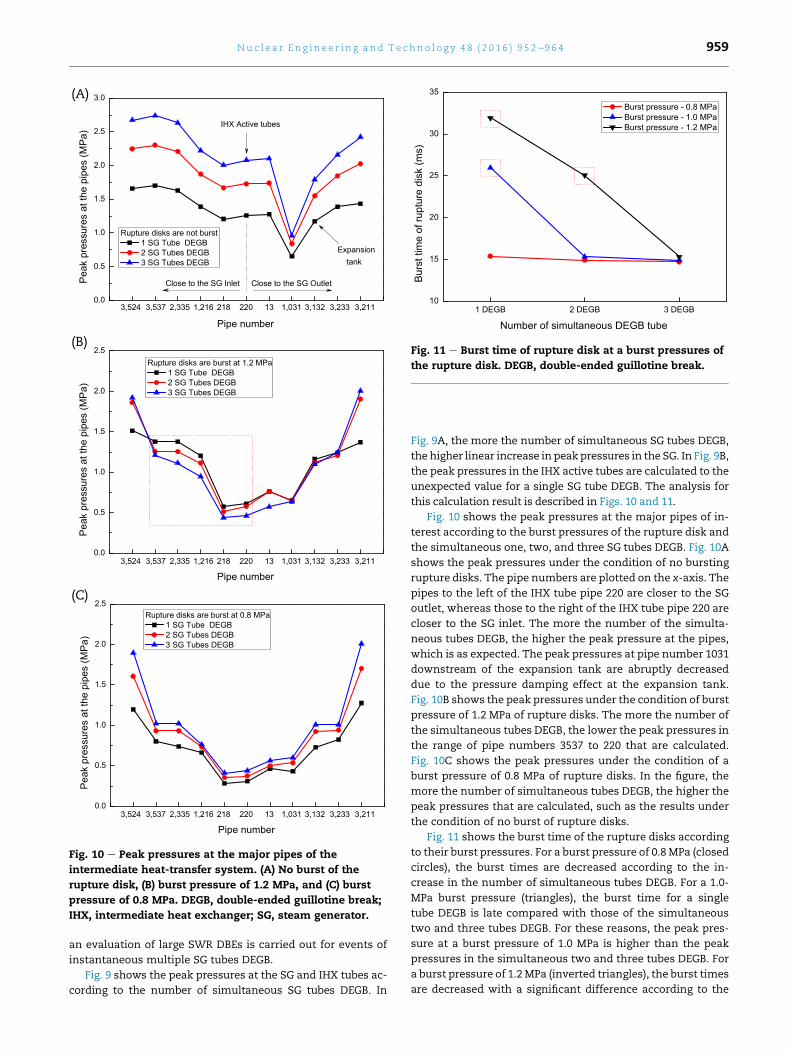
Fig. 10 e Peak pressures at the major pipes of the
intermediate heat-transfer system. (A) No burst of the
rupture disk, (B) burst pressure of 1.2 MPa, and (C) burst
pressure of 0.8 MPa. DEGB, double-ended guillotine break;
IHX, intermediate heat exchanger; SG, steam generator.
1 DEGB 2 DEGB 3 DEGB10
15
20
25
30
35
Bur
st ti
me
of ru
ptur
e di
sk (m
s)
Number of simultaneous DEGB tube
Burst pressure - 0.8 MPa Burst pressure - 1.0 MPa Burst pressure - 1.2 MPa
Fig. 11 e Burst time of rupture disk at a burst pressures of
the rupture disk. DEGB, double-ended guillotine break.
Nu c l e a r E n g i n e e r i n g a n d T e c h n o l o g y 4 8 ( 2 0 1 6 ) 9 5 2e9 6 4 959
an evaluation of large SWR DBEs is carried out for events of
instantaneous multiple SG tubes DEGB.
Fig. 9 shows the peak pressures at the SG and IHX tubes ac-
cording to the number of simultaneous SG tubes DEGB. In
Fig. 9A, the more the number of simultaneous SG tubes DEGB,
the higher linear increase in peakpressures in the SG. In Fig. 9B,
the peak pressures in the IHX active tubes are calculated to the
unexpected value for a single SG tube DEGB. The analysis for
this calculation result is described in Figs. 10 and 11.
Fig. 10 shows the peak pressures at the major pipes of in-
terest according to the burst pressures of the rupture disk and
the simultaneous one, two, and three SG tubes DEGB. Fig. 10A
shows the peak pressures under the condition of no bursting
rupture disks. The pipe numbers are plotted on the x-axis. The
pipes to the left of the IHX tube pipe 220 are closer to the SG
outlet, whereas those to the right of the IHX tube pipe 220 are
closer to the SG inlet. The more the number of the simulta-
neous tubes DEGB, the higher the peak pressure at the pipes,
which is as expected. The peak pressures at pipe number 1031
downstream of the expansion tank are abruptly decreased
due to the pressure damping effect at the expansion tank.
Fig. 10B shows the peak pressures under the condition of burst
pressure of 1.2 MPa of rupture disks. The more the number of
the simultaneous tubes DEGB, the lower the peak pressures in
the range of pipe numbers 3537 to 220 that are calculated.
Fig. 10C shows the peak pressures under the condition of a
burst pressure of 0.8 MPa of rupture disks. In the figure, the
more the number of simultaneous tubes DEGB, the higher the
peak pressures that are calculated, such as the results under
the condition of no burst of rupture disks.
Fig. 11 shows the burst time of the rupture disks according
to their burst pressures. For a burst pressure of 0.8 MPa (closed
circles), the burst times are decreased according to the in-
crease in the number of simultaneous tubes DEGB. For a 1.0-
MPa burst pressure (triangles), the burst time for a single
tube DEGB is late compared with those of the simultaneous
two and three tubes DEGB. For these reasons, the peak pres-
sure at a burst pressure of 1.0 MPa is higher than the peak
pressures in the simultaneous two and three tubes DEGB. For
a burst pressure of 1.2MPa (inverted triangles), the burst times
are decreased with a significant difference according to the

0 50 100 1500
1
2
3
4
5
6
7
Pre
ssur
e at
SG
tube
bre
ak p
oint
(MP
a)
Time (ms)
Rupture disk is burst (at hot leg) Rupture disk is burst (at cold leg)
Fig. 12 e Pressures histories at the steam generator (SG)
tube break point. Simultaneous five SG tubes double-ended
guillotine break, single failure.
Nu c l e a r E n g i n e e r i n g a n d T e c h n o l o g y 4 8 ( 2 0 1 6 ) 9 5 2e9 6 4960
increase in the number of simultaneous tubes DEGB. Although
the initially generated pressures in the SG can be large ac-
cording to the increase in the number of simultaneous tubes
DEGB, the pressure waves that propagated to the IHX tube can
be lower due to the burst time of the rupture disks. Conse-
quently, the faster the burst of the rupture disks, the lower the
peak pressure that can propagate to the IHX tube due to
depressurization in the affected IHTS loop after the burst of
the rupture disks.
Based on the results in the prior section, an evaluation of
five simultaneous tubes DEGB for a large leak SWR is carried
out. In addition, the single-failure criteria are applied to the
rupture disks as a safety measure. Based on these criteria it
assumed that one out of two rupture disks failed in the
calculation.
0 50 100 1500
1
2
3
4
5
6
7
Pre
ssur
es a
t IH
X a
ctiv
e tu
bes
(MP
a)
Time (ms)
Rupture disk is burst (at hot leg) Rupture disk is burst (at cold leg)
Fig. 13 e Pressures histories at the intermediate heat
exchanger (IHX) active tubes. Simultaneous five steam
generator tubes double-ended guillotine break, single
failure.
Fig. 12 shows the pressure histories calculated at the
middle break level of the SG tube. In the figure, the red curve
means that the single failure criteria are applied to the rupture
disk connected with the cold leg. Thus, during the calculation
time, the rupture disk connected with the hot leg normally
bursts, but the rupture disk connected with the cold leg is
assumed to have failed. In addition, the blue curve is a result
of applying a reverse assumption. From the results of the two
cases, the build peak pressures are calculated to equal values
of approximately 6.2 MPa regardless of the connected position
of the rupture disks. Because of the cushion effects of the re-
action product gas volume and the burst of the rupture disk,
the initial peak pressures are gradually decreased as time
passes. Based on the installed level of the rupture disks, the
level of the rupture disk connected with hot leg is higher than
the level of the rupture disk connected with the cold leg. For
this reason, in the case of a burst of the rupture disk connected
with the hot leg, the initially generated pressure waves
remained at a high state in the SG.
Fig. 13 shows the pressure histories at the IHX inlet and
outlet. As shown in the figure, before reaching the pressure
waves propagated from the SG, the initial pressures are
constantly maintained until approximately 40 ms. As
described in Fig. 12, the peak pressure in the case of burst of a
rupture disk connected with the hot leg is built higher than
that of the cold leg due to the installed level of the rupture
disk. For five simultaneous SG tubes DEGB, the peak pressure
of the IHX tube is calculated as approximately 2.5 MPa.
3. Transient analysis for SWR
3.1. Analysis methods and MARS-LMR input modeling
If an SWR occurs, the integrity of the reactor vessel must be
retained and the fuel rods should satisfy the safety acceptance
criteria. In the PGSFR, general transients are analyzed using
the MARS-LMR [10]. A liquidmetal coolant property table, wall
heat-transfer coefficients, and the friction factor correlations
related to a liquid metal reactor system were added to the
MARS code [11] to be used in an analysis of the transients for a
liquid metal-cooled reactor system.
As described in the prior section, the reactor is not
scrammed until the rupture disk in the SWRPRS bursts
because the RPS signal is coupled with the burst of the rupture
disk. For a conservative calculation, the transient calculation
is initiated under the assumption that the sodium inventory of
a failed IHTS loop is fully drained into the SDT. The mass flow
rate is set to zero formodeling the sodium of the affected IHTS
loop.
A few conservative assumptions such as a loss of offsite
power (LOOP) and single failure criteria for DHRS are applied
to the transient calculation. For DHRS, one ADHRS train is
failed by the assumption of the single failure criteria and one
PDHRS train is failed for the maintenance. The event scenario
for a transient calculation is as follows: (1) In 5 seconds, the
mass flow rate of the failed IHTS loop sodium is decreased to
zero. In an actual scenario, however, the amount of sodium
drained in the SDT can be restricted by the geometrical
arrangement of the IHTS, and drain time can be longer than 5

Table 2 e Event scenario for sodiumewater reaction.
Event scenario Time (sec)
1 Initial condition for event:
Because of steam generator (SG) tubes double-
ended guillotine break, the sodiumewater
reaction event occurs in the SG.
The sodium in the one failed intermediate heat-
transfer system (IHTS) loop is totally drained.
(mass flow rate at flow BC ¼ 0.0 kg/sec)
5
2 Reactor trip signal is initiated 5
3 Reactor þ loss of offsite power (2 reactor
coolant pumps, 1 IHTS pump, and 1 feed water
pump are stopped)
10
4 Air dampers are fully opened (at the natural-draft
sodium-to-air heat exchanger/forced-draft
sodium-to-air heat exchanger)
15
5 Maximum temperature in the fuel
rods: 881.8 K (608.7�C)120
Nu c l e a r E n g i n e e r i n g a n d T e c h n o l o g y 4 8 ( 2 0 1 6 ) 9 5 2e9 6 4 961
seconds; (2) a reactor trip signal occurs at 5 seconds; (3)
considering the reactor trip signal delay time and LOOP
assumption, reactor, reactor coolant pump (RCP), IHTS pump,
and feed water pump are simultaneously stopped at 10 sec-
onds. Compared with a light water reactor, the 5-second
reactor trip signal delay time is a conservative assumption
with respect to the PHTS cooling; and (4) air dampers in the
DHRS are fully opened at 15 seconds. In addition, 10 seconds
applied to open air dampers of the DHRS to remove the decay
heat from the core is a conservative assumption. Table 2
shows a brief event scenario during the transient calculation.
Fig. 14 shows the nodalization for the PHTS and a scheme
for modeling the failed IHTS loop. In Fig. 14A, the PHTS is
composed of a hot pool and cold pool. The four IHXs are used
to transfer the heat generated from the core to the IHTS, and
the heat structures for the IHX tubes aremodeled. The volume
of the IHX shell is composed of 24 nodes and connected with
Node 105 for modeling the lower cold pool. The upper cold
pool is modeled as Node 100 and the upper volume of this
node is filled with an inert cover gas. The two RCPs (Node 115
and 145) connected with the Node 105 are supplied with so-
dium coolant of the cold pool to the inlet plenum (Node 168) of
the core. The inflow sodium to the inlet plenum is heated
upon passing through the core (Nodes 175, 178, 180, and 190)
and transferred to the core outlet (Node 200). Considering the
single failure criteria of the one train ADHRS and the main-
tenance of the one train PDHRS, the DHRS is modeled as one
train ADHRS and one train PDHRS. The DHRS is composed of
the two DHX nodes (Nodes 242 and 252), which are submerged
into the cold pool, loop pipes, the natural-draft sodium-to-air
heat exchanger (AHX; Node 815), and the forced-draft sodium-
to-air heat exchanger (FHX; Node 915) to exchange heat with
the air.
Fig. 14B shows the scheme of one failed IHTS loop for
modeling the SWR with MARS-LMR. To simulate the behavior
of the failed IHTS under normal operation conditions, two
time-dependent volumes are applied to the hot leg and cold
leg, respectively. As a pressure boundary condition, 0.536 MPa
for the sodium pressure is applied to the time-dependent
volume connected with the hot leg. As a flow boundary con-
dition, 378.9 kg/s mass flow rate of sodium is applied to the
time-dependent junction prior to connecting the time-
dependent volume with the cold leg. When an SWR occurs,
the mass flow rate of the cold leg is set to zero to model the
sodium inventory dump to the SDT in the failed IHTS loop.
3.2. Evaluation results and discussion
Based on the event scenario for a transient calculation, the
evaluation of the PHTS and fuel rods for a large leak SWR is
carried out. Fig. 15 shows the behaviors in the PHTS during a
transient calculation. Fig. 15A shows the mass flow rates in
RCPs 1 and 2, which are submerged in the reactor vessel.
During the initial 5 seconds, the rated mass flow rate of the
RCP in the normal operation is constantly maintained. The
transient calculation is initiated at 5 seconds. By the LOOP
assumption, the RCPs are simultaneously stopped and the
rated mass flow rates start to decrease at about 10 seconds,
considering the reactor trip delay time of 5 seconds. The mass
flow rates are gradually decreased by the failure of the RCPs
power during approximately 15 seconds, and the natural cir-
culation flow is then built and maintained. Fig. 15B shows the
behavior of the reactor power during the transient calculation.
During the initial 5 seconds, the rated power of 392.2 MWt is
constantly maintained. Considering the LOOP assumption
and reactor trip signal delay time, the reactor is stopped due to
the shutdown control rod insertion for scramming the reactor
at 10 seconds, and the reactor power is then rapidly decreased
in a few seconds. After this time, the decay heat power [12]
generated from the core is gradually decreased over time.
Fig. 16 shows the heat-transfer rates in the four IHXs and
one intact SG. In Fig. 16A, the heat-transfer rates of 100.58 MW
of IHX 1 and 2 in relation to the failed IHTS loop are decreased
by the flow boundary condition for the mass flow rates at 5
seconds, and these then reach zero at approximately 20 sec-
onds. Because of the LOOP assumption, the heat-transfer rates
of the intact IHX 3 and 4 start to decrease at 10 seconds and
then maintained by a natural circulation flow after 30 sec-
onds. The heat-transfer rate of 201.58 MW of the intact SG
shows an equal behavior with the intact IHX 3 and 4. Fig. 16B
shows the heat-transfer rates in the AHX and FHX during a
transient calculation. Under normal operation conditions, the
sodium of the PDHRC and ADHRC are circulated to prevent
solidification and to remove the specified heat in the PHTS. For
this reason, the initial heat-transfer rates are constantly
maintained until 15 seconds. After 15 seconds, the heat-
transfer rates are increased by opening the air dampers by
the actuation of the decay heat removal signal. At the initial
time, the heat-transfer rates of the shell side in the AHX and
FHX are significantly increased higher than those on the tube
side due to the direct influences by the opening of the air
dampers. After 1,000 seconds, the heat-transfer rates of the
ADHRS are maintained higher than those of the PDHRS due to
the forced circulation flow.
Fig. 17 shows the maximum temperature of the fuel rods
during the transient calculation. Before 10 seconds, the tem-
perature of the fuel rods is maintained at approximately
900.7 K (627.6�C). Upon initiating the shutdown control rod
insertion by the RPS trip signal actuation, the temperature of
the fuel rods is abruptly decreased to approximately 701.5 K
(428.4�C). At the suspension of the two RCPs, one intact IHTS

Fig. 14 e (A) Nodalization and (B) scheme for multidimensional analysis of reactor safety-liquid metal reactor input. BC,;
IHTS, intermediate heat-transfer system; IHX, intermediate heat exchanger; SG, steam generator; SWR, sodiumewater
reaction; TMDP.
Nu c l e a r E n g i n e e r i n g a n d T e c h n o l o g y 4 8 ( 2 0 1 6 ) 9 5 2e9 6 4962

0 10 20 30 40 50 60 70 80 90 1000
200
400
600
800
1,000
1,200
Mas
s flo
w ra
te (k
g/s)
Time (s)
RCP-1 RCP-2
0 10 20 30 40 500
50
100
150
200
250
300
350
400
450
Rea
ctor
pow
er (M
W)
Time (s)
(A)
(B)
Fig. 15 e Behavior of the reactor coolant pump. (A) Mass
flow rate and (B) reactor power during a transient
calculation. RCP, reactor coolant pump.
0 10 20 30 40 50 60 70 80 90 1000
50
100
150
200
250
Hea
t tra
nsfe
r rat
e (M
W)
Time (s)
1 IHTS failed IHX-1 (failed) IHX-2 (failed) IHX-3 (intact) IHX-4 (intact) SG-2 (intact)
10 100 1,000 10,0000.5
1.0
1.5
2.0
2.5
3.0
3.5
4.0
Hea
t tra
nsfe
r rat
e (M
W)
Time (s)
AHX tube - PDHRS AHX shell - PDHRS FHX tube - ADHRS FHX shell - ADHRS
(A)
(B)
Fig. 16 e Heat-transfer rates. (A) Of the intermediate heat
exchanger and (B) of the decay heat removal system during
a transient calculation. ADHRS, active decay heat removal
system; AHX, natural-draft sodium-to-air heat exchanger;
FHX, forced-draft sodium-to-air heat exchanger; IHTS,
intermediate heat-transfer system; IHX, intermediate heat
exchanger; PDHRS, passive decay heat removal system;
SG, steam generator.
10 100 1,000 10,000 100,000650
700
750
800
850
900
950
Tem
pera
ture
of f
uel r
ods
(K)
Time (s)
Fig. 17 e Temperature of the fuel rods during a transient
calculation.
Nu c l e a r E n g i n e e r i n g a n d T e c h n o l o g y 4 8 ( 2 0 1 6 ) 9 5 2e9 6 4 963
pump and one feed water pump by the LOOP assumption, the
temperature increases due to the decay heat from the core
and the sensible heat in the PHTS. Themaximum temperature
of the fuel rods is calculated as approximately up to 881.8 K
(608.7�C) at 120 seconds. After 100 seconds, the temperature of
the fuel rods is gradually decreased by the operation of the
DHRS after 15 seconds. For the one IHTS loop failure event due
to a large leak SWR, the maximum temperature of the fuel
rods is well within the normal operating temperature range
for the fuel rods and core.
3.3. Conclusions
For sodium water reaction events by the leak or break of SG
tubes, the evaluation of the integrity of the IHTS and PHTS is
performed using the SWAAM-II and MARS-LMR codes in the
PGSFR.
Based on the calculation results obtained using SWAAM-II,
the peak pressure in the SG is generated at the middle level of
the SG tube. Because of the pressure damping effect in the
expansion tank, the pressure waves propagated to the hot leg
direction are calculated lower than those toward the cold leg

Nu c l e a r E n g i n e e r i n g a n d T e c h n o l o g y 4 8 ( 2 0 1 6 ) 9 5 2e9 6 4964
direction. For a single SG tube DEGB, the generated peak
pressure of the SG and IHX tube are calculated to be approx-
imately 3.1 MPa and 0.65 MPa, respectively. For a five SG tubes
DEGB, the peak pressures in the SG and IHX tube are calcu-
lated as 6.2 MPa and 2.5 MPa, respectively.
In the evaluation of the integrity of the PHTS through the
MARS-LMR, the maximum temperature of the fuel rods is
calculated as approximately 881.8 K (608.7�C) at 120 seconds.
Although conservative assumptions such as the reactor trip
delay time, LOOP assumption, and single failure criteria are
applied to the event scenario, the integrity of the fuel rod iswell
within the normal operating temperature range for one IHTS
failure event due to the five simultaneous SG tubes break.
Conflicts of interest
All authors have no conflicts of interest to declare.
Acknowledgments
This work was supported by the National Research Founda-
tion of Korea (NRF) grant funded by the Korean government
MSIP (No. 2012M2A8A2025634).
Nomenclature
C total heat capacity of the reaction products;
h enthalpy of injected water;
hN enthalpy of sodium;
m unreacted water mass in the bubble;
m0 reacted water mass;
p bubble pressure;
qf heat loss at the bubbleesodium interface;
qs heat loss to solid inclusions such as the tube bundle;
T bubble temperature;
Tref reference temperature to measure all energy
quantities;
u internal energy of unreacted water in the bubble;
V bubble volume;
a0 mass of hydrogen gas generated per unit mass of
water reacted;
aN mass of sodium per unit mass of water reacted; and
DH heat of reaction.
r e f e r e n c e s
[1] D.A. Greene, Sodium-water reaction phenomena associatedwith small leaks in LMFBR steam generator, in: Proceedingsof the Third International Conference, Oxford, Vol. 1, 1984,pp. 13e21.
[2] International Atomic Energy Agency, Liquid Metal CooledReactors: Experience in Design and Operation (Rep. No. IAEA-TECDOC-1569), International Atomic Energy Agency, Wien(Austria), 2007.
[3] H.-T. Chien, S. Bakhtiari, S.-H. Sheen, Interim ProgressReport: Steam Generator Leak Detection System (Rep. No.ANL-KAERI-SFR-13-26), Argonne National Laboratory,Chicago, 2013.
[4] P.M. Scott, R.J. Olson, G.M. Wilkowski, Development ofTechnical Basis for Leak-Before-Break Evaluation Procedures(Rep. No. NUREG/CR-6765), U.S. Nuclear RegulatoryCommission, Rockville (MD), 2002.
[5] Clinch River Breeder Reactor Project, Large Sodium-WaterReaction: Preliminary Safety Analysis Report, U.S., 1975(Chapter 15.3e46)
[6] D.A. Greene, D.W. Sandusky, Results of small leak behaviorand damage propagation tests in the U.S, in: Presented atthe 2nd Joint US/USSR Seminar on the Development ofSodium-Cooled Fast Breeder Steam Generators, USSR, July26, 1976.
[7] E. Wachi, T. Inoue, Detection system of SG tube failure inMonju to limit failure within design basis leak, Presented atIAEA/IWGFR Specialist’ Meeting on “Steam Generator:Failure and Failure Propagation,” Aix-en-Provence, France,September 26e28, 1990.
[8] P. Chellapandi, Studies towards safety related to sodium inIndia, Presented at 2nd joint GIF-IAEA/INPRO ConsultancyMeeting on Safety Aspects of SFRs, India Gandhi Centre forAtomic Research, India, 2011.
[9] Y.W. Shin, C.K. Youngdahl, User Manual for the Sodium-Water Reaction Analysis Computer Code SWAAM-II (Rep. No.ANL-83-75), Argonne National Laboratory, Chicag, 1975.
[10] K.-S. Ha, H.-Y. Jeong, Comparison of the decay heat removalsystems in the KALIMER-600 and DSFR, Nucl. Eng. Technol.44 (2012) 535e542.
[11] J.J. Jeong, K.-S. Ha, B.D. Chung, W.J. Lee, Development ofmulti-dimensional thermal-hydraulic system code, MARS1.3.1, Ann. Nucl. Energy 26 (1999) 1611e1642.
[12] American National Standards Institute (ANSI), AmericanNational Standard for Decay Heat Power in Light WaterReactors, ANSI, Washington DC, WA, 1979. ANSI/ANS 5.1.