available with the optional - '+domain name+' · 2 most accessible basin • access from...
TRANSCRIPT

Bulletin 220K
Available with the Optional
Water Treatment SystemMember MCAA
Mechanical Contractors Association of America
Mr. GoodTower®

2
Most Accessible Basin
• Access from all four sides
• Large openarea simplifiesmaintenance
• Basin may beinspected withpumps running
©2008 EVAPCO, Inc.
Optional Pulse~Pure®
Water Treatment SystemThe ATW is available with EVAPCO’s NEW optionalPulse~Pure® non-chemical water treatment system.The Pulse~Pure® Water Treatment System utilizespulsed-power technology to provide CHEMICAL FREEWater Treatment. EVAPCO’s Pulse~Pure® system isan environmentally responsible alternative for treatingwater in evaporative cooled equipment. It does notrelease harmful by-products to the environment andeliminates chemicals completely from cooler drift andblowdown. The Pulse~Pure® system delivers short,high-frequency bursts of low energy electromagneticfields to the recirculating water in the ATW and will:
• Control bacteria to levels well below traditionalchemical water treatment
• Control the formation of mineral scale
• Save water by operating at higher cycles ofconcentration
• Yield corrosion rates equivalent to chemicalwater treatment
Super Low Sound Fan
• Extremely wide sloped fanblades for sound sensitiveapplications.
• One piece molded heavy dutyconstruction.
• 9-15 dB(A) sound reduction.
Louver Access Door
• Louver access door is available onmodels with 5 and 6 ft. louver sizes
• Hinged assess panel with quickrelease mechanism
• Allows easy access to performroutine maintenance and inspectionof the makeup assembly, strainerscreen and basin
NEW!
Since its founding in 1976, EVAPCO,Incorporated has become an industry leader
in the engineering and manufacturing of qualityheat transfer products around the world.EVAPCO’s mission is to provide first class serviceand quality products for the following markets:
� Industrial Refrigeration� Commercial HVAC� Industrial Process� Power
EVAPCO’s powerful combination of financialstrength and technical expertise has establishedthe company as a recognized manufacturer ofmarket-leading products on a worldwide basis.EVAPCO is also recognized for the superiortechnology of their environmentally friendlyproduct innovations in sound reduction andwater management.
EVAPCO is an employee owned company with astrong emphasis on research & development andmodern manufacturing plants. EVAPCO hasearned a reputation for technologicalinnovation and superior product quality byfeaturing products that are designed to offerthese operating advantages:
� Higher System Efficiency� Environmentally Friendly� Lower Annual Operating Costs� Reliable, Simple Operation and
Maintenance
With an ongoing commitment to Research &Development programs, EVAPCO provides themost advanced products in the industry–Technology for the Future, Available Today!
EVAPCO products are manufactured in 16locations in 7 countries around the world andsupplied through a sales network consisting ofover 170 offices.
®

3
Unique Fan Drive System
• Power-band belts for better lateral rigidity
• Advanced design aluminum fan blades
• Non-corroding cast aluminum sheaves
• Heavy-duty fan shaft bearings with L-10 life of 75,000 - 135,000 hrs
• All other components constructed of corrosion resistant materials
• Totally enclosed fan motors assure long life
WST Air Inlet Louvers(Water and Sight Tight)
• Easily removable for access
• Improved design to keep sunlightout–preventing biological growth
• Keeps water in while keeping dirtand debris out
(Patent Pending)
Efficient Drift Eliminators
• Advanced design removesmist from the leavingairstream
• Made from corrosionresistant PVC for long life
(U.S. Patent No. 6315804)
PVC Spray DistributionHeader with ZM® Nozzles
• Nozzles are threaded intoheader at proper orientation
• Large orifice fixed positionnozzles prevent clogging
• Threaded end caps for easeof cleaning
Design and Construction FeaturesThe ATW line of Closed Circuit Coolers reflects EVAPCO’s commitment to product development.Its advanced design provides owners with many operational and performance advantages.The new owner oriented features of the ATW along with the independent certification of IBCcompliance reinforce the ATW’s position as the premier closed circuit cooler for the HVAC industry.
NEW & Improved!
®
noitacifitreCdaoLdniWdnacimsieSsrewoTgnilooCTU,TAU,SSU,TAsresnednoCevitaropavECTHdnaE-CTA
srelooCtiucriCdesolCWTAehtteeMotderutcafunaMdnadengiseDstinU
:fostnemeriuqeRdaoLdniW&cimsieS0005APFN7-ECSA6002CBI
:yBnoitacifitreCtnednepednI
AP622-5178334:rebmuNlaireSCBI
IBC Certification Label
• Provided with everyunit to indicate inde-pendent certificationand compliance
Easy Field Assembly
• A new field assembly seamdesign which ensures easierassembly and fewer fieldseam leaks
• Self-guiding channels guidethe coil casing section intoposition improving thequality of the field seam
• Eliminated up to 66% of fasteners
(Patent Pending)
NEW!
NEW!

4
IBC CO M P L I A N C E
®
What is IBC?International Building CodeThe International Building Code (IBC) is a comprehensiveset of regulations addressing both the structural designand the installation requirements for building systems –including HVAC and industrial refrigeration equipment.The IBC is intended to replace BOCA’s The NationalBuilding Code, ICBO’s Uniform Building Code and SBCCI’sStandard Building Code.
Compared to previous building codes that consideredonly the building structure and component anchorage,the requirements contained within the IBC addressanchorage, structural integrity, and the operationalcapability of a component following either a seismic orwind load event. Simply stated, the IBC codeprovisions require that evaporative coolingequipment, and all other components permanentlyinstalled on a structure, must be designed to meetthe same seismic and wind load forces as thebuilding to which they are attached.
How Does IBC 2006 Apply to ClosedCircuit Coolers?Based on the project zip code and site design factors, cal-culations are made to determine the equivalent seismic“g force” and wind load (in pounds per square foot – psf)on the unit. The closed circuit cooler must be designed towithstand the greater of either the seismic or wind load.
More than 80% of the United States has design criteriaresulting in a seismic design force of 1.0g or below. Thesesites will be provided with the standard ATW structuraldesign. An upgraded structural design is available forinstallations with design criteria resulting in “g forces”
greater than 1.0g. The highest “g force” location inNorth America is 5.12g. The highest wind load shown onthe maps is 170 mph, which is approximately equal to 145psf velocity pressure. Therefore, the upgraded struc-tural design package option for the New AT isdesigned for 5.12g and 145 psf making it applicableto ALL building locations in North America.
Seismic DesignThe attached chart from the US Geological SurveyWebsite http://www.usgs.gov/ shows the potential seismicactivity in the United States. Buildings constructed in thered, orange and yellow areas of the map may require theupgraded ATW construction design based on the site seis-mic design factors and should be reviewed closely.Critical use facilities, such as hospitals, are also more likelyto require the upgraded design.
The project architect or civil engineer is responsible fordetermining the seismic design factors to be used for thebuilding design. A mechanical consulting engineer and/ordesign build contractor then applies these factors to aseries of charts and graphs to determine the appropriateseismic design factors based on the location of the instal-lation and ultimately the “importance” of the facility.The specific factors necessary for seismic design as well asa sample seismic calculation are shown on the next page.
32+
Highest Hazard
Lowest Hazard
%g
24-3216-248-164-82-40-2
Map courtesy US Geological Survey website
In its continuing commitment to be the leaders in evaporative cooling equipment design and services,EVAPCO ATW Closed Circuit Coolers are now Independently Certified to withstand both Seismic
and Wind Loads in ALL Geographic Locations and Installations in accordance with IBC 2006.
The New ATW is offered with a choice of TWOstructural design packages:
• Standard Structural Design – For projects with≤ 1.0g seismic or 145 psf wind loads
• Upgraded Structural Design – Required forprojects with > 1.0g seismic or 145 psf max wind loads

5
®
Wind DesignThe IBC 2006 code book includes a map of basic windspeed (3-second gust) by contour lines. However, localregulations may be more stringent than these publishedspeeds. The specific factors necessary for wind load as wellas a sample wind load calculation are shown on Page 7.
Whichever design force - seismic or wind - is moresevere for the building, governs the design of thebuilding and all attached equipment.
Design ImplementationEVAPCO applies the given seismic and wind load informa-tion provided by the mechanical consulting engineer todetermine the equipment design necessary to meet IBCrequirements. This process ensures that the mechanicalequipment and its components are compliant per theprovisions of the IBC as given in the plans and specifica-tions for the project. For design build projects, EVAPCO isequipped to look up the information and submit theresulting loads for approval.
Independent CertificationPer the most recent edition of the code, the EVAPCOcompliance process included an exhaustive analysis by anindependent approval agency. As required by theInternationalBuilding Code,EVAPCO sup-plies a certifi-cate of compli-ance as part ofits submittaldocuments. Thecertificate ofcompliancedemonstrates
that the equipment has been independently tested andanalyzed in accordance with the IBC seismic and windload requirements. Evapco has worked closely with theindependent approval agency, The VMC Group, to com-plete the independent equipment testing and analysis.
If the seismic “g force” and wind “psf” load requirementsfor the project site are known, EVAPCO’s online equip-ment selection software, iES, will allow you to choose therequired structural design package – either standard con-struction or upgraded construction.
If the project requirements are unknown, the followingcalculations must be completed.
For further questions regarding IBC compliance, pleasecontact your local EVAPCO Representative or visitwww.evapco.com.
Seismic Load CalculationsThe data required to calculate the seismic load are:
Occupancy Category – I, II, III or IV depending on thenature of the building occupancy. Table 1604.5 in the IBC2006 Code Book defines each of the four categories indetail. In summary the four categories are:
• Category I - structures that represent a low hazardto human life in the event of a failure.
• Category III - structures that represent a substantialhazard to human life in the event of a failure.
• Category IV - structures designated as essentialfacilities.
• Category II - any structures not listed in I, III or IV.
Site Classification – A, B, C, D, E or F based on the typesof soil and their engineering properties. Table 1613.5.2 inthe IBC 2006 Code Book defines each of the categories indetail. IBC specifies site class “D” when soil properties areunknown.
Maximum Spectral Response Acceleration (Ss) –Numerical value found using the U.S. Geological (USGS)data based on the Zip Code of the project. This datapoint can be determined using the Ground MotionParameter Calculator at http://www.usgs.gov/. Note thecalculator assumes a site classification of B for the 0.2 sec-ond maximum Ss. The site coefficient (Fa), defined below,will correct for the actual site classification.
ecnailpmoCfoetacifitreCsrewoTgnilooCTU,TAU,SSU,TA
srelooCtiucriCdesolCWTAsresnednoCevitaropavEE-CTAHTC,
snoisivorPdaoLdniWdnacimsieSehtdeecxeroteemotdeifitrecerA.tcejorpsihtrofsedocgnidliubelbacilppaehtnihtroftes
llagniwollofderutcafunamneebevahstcudorpesehT.smargorpecnarussaytilauqelbacilppa
:sedoCgnidliuBelbacilppA6002CBI7-ECSA0005APFN
:tropeRdecnerefeR78334-AMV
:ycnegAlavorppApuorGgnitlusnoCcimsieSCMV
.secivreSdnastcudorPrefsnarTtaeHnistsilaicepS...OCPAVE 100COCCBIDI
When using the EVAPCO selection software to make aselection, these calculations are already incorporatedinto the selection process. Simply enter the requiredseismic factors and the Seismic Design Force and WindLoad will be calculated automatically!!
IBC CO M P L I A N C E
Wind Load Map Courtesy IBC 2006 Text –See full-sized map for location specific values

Site Coefficient (Fa) – Values ranging from 0.8 to 2.5determined based on the Ss and the Site Classification.Table 1613.5.3(1) in the IBC 2006 Code Book definesthese values.
Design Spectral Response Acceleration (SDS) – A cal-culated value using the values for Ss and Fa.
Amplification Factor (ap) – 2.5 for flexible componentsor flexibly attached components. Due to its low inherentnatural frequencies, most evaporative cooling equipmentfalls under the definition of flexible. Therefore thedefault for Closed Circuit Coolers is 2.5. See Table 13.6-1in the American Society of Civil Engineers (ASCE)Standard 7-05, to which IBC often references, for moreinformation.
Response Modification Factor (Rp) – 2.5 for non-isolat-ed evaporative cooling equipment. 2.0 for vibration iso-lated evaporative cooling equipment. Table 13-6.1 ofASCE 7-05 provides additional information.
Component Operating Weight (Wp) – This weightterm has been removed from the equation below,because EVAPCO is expressing the force in terms of g’sand not lbs.
Importance Factor (Ip) – 1.5 for Occupancy Category IV,life safety components required to function after a seis-mic event or component containing hazardous content.1.0 for all other components. ASCE 7-05 Section 13.1.3provides additional detail on importance factors.
Installation Location (Z/h) – 0 for units installed atground level. 1.0 for units installed on a rooftop. PerASCE 7-05 Section 13.3, z = the height of the point ofattachment of the component and h = the relative roofheight.
Seismic Design Force, (Fp) – “G-force” that the unitmust be able to withstand. This number is calculatedusing the factors described above. The New ATW isoffered with a choice of two structural design packages,consisting of:
– Standard Structural Design ≤ 1.0g– Upgraded Structural Design – up to 5.12g (the
maximum value for North America)
Seismic Load Sample Calculation
The following example demonstrates the procedure fordetermining which structural design package aCommunity Hospital located in Charleston, SC (zip code29401) would require under the latest version of IBC. Inthis example, the closed circuit cooler will be installed ona roof, approximately 60 feet above grade. The unit willalso be installed with a vibration isolation system.
Step 1: Calculate the Design Spectral Response
Acceleration (SDS)
Where:
SS = 1.495; using the USGS Ground Motion ParameterCalculator
Fa = 1.0; from Table 1613.5.3(1) in the IBC 2006 CodeBook assuming a Site Classification of D
Step 2: Calculate the Seismic Design Force (Fp )
Where:
ap = 2.5; the default for cooling towers and closedcircuit coolers
SDS = 0.9966; as calculated in Step 1
Wp = 1.0; the default for cooling towers and closedcircuit coolers
Rp = 2.0; the default for isolated equipment
Ip = 1.5; the default for life safety components
z/h = 1.0; the default for units on a rooftop
In order to meet Code requirements, the unit and itsanchorage must be constructed to withstand 2.24g. Thiswill require that the upgraded structure option be chosento meet the seismic requirements of this project. Becausethe seismic load requires the upgraded structural design,the wind load calculation results will not change thedesign and are not required for this analysis.
6
®
SDS (Fa)(Ss)= 23 (1.0)(1.495)=0.9966= 2
3
FP 1+2 zh
= =0.4 (aP)(SDS)(WP) (1+2(1))=2.24g
RP
IP( )0.4 (2.5)(0.9966)(1)
2.01.5( )
( )
IBC CO M P L I A N C E
SDS (Fa)(Ss)= 23

Wind Load CalculationsNote, both the standard construction and the upgradedconstruction ATW Closed Circuit Cooler are designed tomeet a wind load of 145 psf. Therefore, the followingdetails are provided for informational purposes only.
The data required to calculate the wind load are:
Basic Wind Speed (V) – Numerical value, in miles perhour (mph) found in ASCE 7-05 Figures 6-1 (A,B,C).
Wind Directionality Factor (Kd) – 0.85 for buildingcomponents and cladding. Table 6-4 of ASCE 7-05 pro-vides additional information.
Occupancy Category – I, II, III or IV depending on thenature of the building occupancy. Table 1604.5 in theIBC 2006 Code Book defines each of the categories indetail. This is the same Occupancy Category used inSeismic calculations.
Importance Factor (I) – Numerical value between 0.77and 1.15 based on the Basic Wind Speed and theOccupancy Category. These values are found in Table 6-1of ASCE 7-05.
Exposure Category – B, C or D as defined in Section6.5.6.3 of ASCE 7-05.
Component Elevation (z) – The anchorage height ofthe unit in feet.
Nominal Height of the Atmospheric Boundary Layer(zg) - Numerical value based on Exposure Category. Thesevalues are found in Table 6-2 of ASCE 7-05.
3 second Gust-Speed power Law Exponent (α) -Numerical value based on Exposure Category. Thesevalues are found in Table 6-2 of ASCE 7-05.
Velocity Pressure Exposure Coefficient (Kz) – Acalculated value using the values for zg and α.
Topographic Factor (Kzt) – 1.0 default whentopographic effects are not a factor. ASCE 7-05 Section6.5.7 provides additional detail on topographic factors.
Velocity Pressure (qz) – This number in pounds persquare foot (psf) is calculated using the factors describedabove. The New ATW is offered with a choice of twostructural design packages, consisting of:
– Standard Design and Upgraded Structural Design –both up to 145 psf (the maximum value for NorthAmerica)
Wind Load Sample Calculation
The following example demonstrates the procedure todetermine which structural design package aCondominium Building located in Miami, FL (zip code33101) would require under the latest version of IBC. Inthis example, the closed circuit cooler will be installed onthe top of the 60 foot tall building.
Step 1: Calculate the Exposure Category Coefficient (Kz)
Where:
z = 60; Installation Height
zg = 700; from ASCE 7-05 Table 2 using an ExposureCategory of D.
α = 11.5; from ASCE 7-05 Table 2 using an ExposureCategory of D.
Step 2: Calculate the Velocity Pressure (qp)
Where:
Kz = 1.31; as calculated above.
Kzt = 1.0; default when topographic effects are not afactor.
Kd = 0.85; default for building components andcladding.
V = 145; wind speed from ASCE 7-05 Figure 6-1.
I = 1.0; Based on an Occupancy Category of II.
In order to meet Code requirements, the unit and itsattachments must be designed and constructed towithstand 59.93 psf. Because the wind load does notdictate the closed circuit cooler design, the seismic loadcalculation must also be completed to determine if theresults will change the unit design.
7
®
( )KZ = 2.01 a
2zzg( )
qp = 0.00256(Kz)(Kzt)(Kd)(V2)(I) =
0.00256(1.31)(1.0)(0.85)(1452)(1.0) = 59.93psf
IBC CO M P L I A N C E
( )( )KZ = 2.01 a
2 2
11.5zzg( ) = 2.01 = 1.31
60700( )

8
Principle of OperationThe process fluid is circulated through the coil of the closedcircuit cooler. Heat from the process fluid is dissipatedthrough the coil tubes to the water cascading downward overthe tubes. Simultaneously, air is drawn in through the air inletlouvers at the base of the cooler and travels upward over thecoil opposite the water flow. A small portion of the water isevaporated which removes the heat. The warm moist air isdrawn to the top of the closed circuit cooler by the fan and isdischarged to the atmosphere. The remaining water falls tothe sump at the bottom of the cooler where it is recirculatedby the pump up through the water distribution system andback down over the coils.
Maintenance Free ZM® Spray NozzleWater Distribution SystemEVAPCO’S Zero Maintenance ZM® SprayNozzle remains clog-free while providingeven and constant water distribution forreliable, scale-free evaporative coolingunder all operating conditionscontinuously delivering 6 GPM to everysquare foot of coil plan area.
The heavy duty nylon ZM® Spray nozzleshave a 1-5/16” diameter opening and a1-1/2” splash plate clearance enablingEVAPCO to use 75% fewer nozzles.Furthermore, the fixed position ZM®
nozzles are mounted in corrosion-freePVC water distribution pipes that havethreaded end caps. Together, theseelements combine to provide unequaledcoil coverage and scale prevention, andmake the industry’s best performingnon-corrosive, maintenance-free waterdistribution system.
Cooling CoilAll Evapco Closed Circuit Coolers utilize EVAPCO’s patentedThermal-Pak® coil design which assures greater operating effi-ciency. The elliptical tube design allows for closer tube spac-ing, resulting in greater surface area per plan area thanround-tube coil designs. In addition, the Thermal-Pak® designhas lower resistance to airflow and also permits greater waterloading, making the Thermal-Pak® coil the most effectivedesign available.
The coils are manufactured from high quality steel tubingfollowing the most stringent quality control procedures.Each circuit is inspected to ensure the material quality andthen tested before being assembled into a coil. Finally, theassembled coil is pneumatically tested at 400 psig under waterto ensure it is leak free.
To protect the coil against corrosion, it is placed in a heavy steelframe and then the entire assembly is dipped in molten zinc(hot-dip galvanized) at a temperature of approximately 800°F.
EVAPCO also offers the option of type 304L stainless steelconstruction using the patented Thermal-Pak® Coil design.
Note: Closed circuit coolers should only be used on sealed,pressurized systems. Continual aeration of the water in anopen system can cause corrosion inside the tubes of thecooler leading to premature failure.
Principle of Operation
Hot Water In
CooledWater Out
Cool DryEntering
Air
Hot SaturatedDischarge Air
Thermal-Pak® Coil by EVAPCO
Round Tube Coil by Others
Thermal-Pak® Coil
U.S. Paten
t No
. 4,755,331
®
ZM® Nozzle
DE S I G N FE AT U R E S

9
Efficient Drift EliminatorsThe ATW is equipped with an efficient drift eliminator systemthat effectively reduces entrained water droplets from the airdischarge to less than 0.001% of the spray water flow rate.
The eliminators are constructed of non-corrosive PVC with amulti-pass design for maximum drift reduction. They areassembled in modular sections for easy removal and access tothe water distribution system.
In addition to reducing drift, the eliminators also function aseffective debris screens which protect the spray system fromsunlight and debris.
Belt Drive Units - 8-1/2’ & 17’ Wide ModelsThe fan motor and drive assembly on these units aredesigned to allow easy servicing of the motor andadjustment of the belt tension from the exterior of the unit.A T.E.F.C. fan motor is mounted on the outside of thesemodels. A protective cover swings away to allow servicingand belt adjustment.
Belt Drive Units - 10’, 12’, 20’, & 24’Wide ModelsThe fan motor and drive assembly are designed to allow easyservicing of the motor and adjustment of the belt tensionfrom the exterior of the unit. The T.E.A.O. fan motor islocated inside the fan casing on a rugged heavy duty motorbase. The innovative motor base also features a uniquelocking mechanism for a positive adjustment.
The motor base isdesigned to swing outthrough a very large,14 square foot accessopening. This allowsfor easy servicing ofthe motor fromoutside of the unit.
Air Intake
Sunlight
Splashout
Debris
Sunlight
Splashout
Debris
External Motor Mount
Motor Base Assembly
Motor Access
Superior Air Inlet Louver andScreen Design – New & ImprovedEVAPCO’S WST Inlet Louvers (patent pending) keep water inand sunlight out of induced draft products. The unique non-planar design is made from light-weight framed PVC sectionswhich have no loose hardware, enabling easy unit access.
Developed with computational fluid dynamics (CFD) software,the louver’s air channels are optimized to maintain fluiddynamic and thermodynamic efficiency and block all line-of-sight paths into the basin eliminating splash-out; even whenthe fans are off. Additionally, algae growth is minimized byblocking all sunlight.
The combination of easy access, no splash-out and minimizedalgae growth saves the end user money on maintenancehours, water consumption and water treatment costs.
®
DE S I G N FE AT U R E S

10
Engineering Data & Dimensions
† Model Number will end in “-2” for units with Series Flow pipingconfiguration. Series Flow units may require additional coil connectionsand will require crossover piping.
†† Heaviest section is the coil/fan section.* Gallons shown is water in suspension in unit and piping. Allow for
additional water in bottom of remote sump to cover pump suction and strainer during operation (12” would normally be sufficient).▲ Unit dimensions and coil connections may vary slightly from catalog. See factory certified prints for dimensions, quantity of coil connections, and
piping configuration. Coil connections are 4” bevel for weld (BFW). Other connection types such as grooved for mechanical coupling or flanged arealso available as options.
ATW CoilModel Heaviest Volume Gallons* Conn. Operating
Number† Shipping Section†† Operating HP CFM HP GPM (Gallons) Required Size Weight H L E U A
24-3G 2,610 2,160 4,130 5 13,600 0.75 135 52 120 6" 3,740 8' 7-1/8" 5' 11-7/8" 31-1/2" 5' 11-5/8" 19-1/2"24-4G 2,980 2,530 4,630 5 13,200 0.75 135 67 120 6" 4,240 9' 2-5/8" 5' 11-7/8" 31-1/2" 6' 7-1/8" 27"24-5G 3,390 2,940 5,160 5 12,810 0.75 135 83 120 6" 4,770 9' 10-1/8" 5' 11-7/8" 31-1/2" 7' 2-5/8" 34-1/2"
Weights Fans Spray Pump Remote Sump ▲ Dimensions ▲
ModelsATW 24-3G to ATW 24-5G
Note: The number of coil connections doubles when the flow rate exceeds 450 GPM on Models ATW24-3G thru ATW 24-5G. This required option is referred to as the High Flow coil configuration.
▲ Remote Sump ConfigurationWhen a remote sump arrangement is selected, the spray pump, suction strainer and associated piping are omitted; the unit is provided with an oversized outlet to facilitate drainage to the remote sump.

11
ModelsATW 36-3F to ATW 36-5FATW 48-3F to ATW 48-5G
Selections for ATW Closed Circuit Coolers are available from EVAPCO’s iES Equipment Selection Program.
Please contact your local sales representative for more information on the iES program.
Note: The number of coil connections doubles when the flow rate exceeds 450 GPM on Models ATW36-3F thru ATW 48-5G. This required option is referred to as the High Flow coil configuration.
† Model Number will end in “-2” for units with Series Flow pipingconfiguration. Series Flow units may require additional coil connectionsand will require crossover piping.
†† Heaviest section is the coil/fan section.* Gallons shown is water in suspension in unit and piping. Allow for
additional water in bottom of remote sump to cover pump suction and strainer during operation (12” would normally be sufficient).▲ Unit dimensions and coil connections may vary slightly from catalog. See factory certified prints for dimensions, quantity of coil connections, and
piping configuration. Coil connections are 4” bevel for weld (BFW). Other connection types such as grooved for mechanical coupling or flanged arealso available as options.
▲ Remote Sump ConfigurationWhen a remote sump arrangement is selected, the spray pump, suction strainer and associated piping are omitted; the unit is provided with an oversized outlet to facilitate drainage to the remote sump.
Engineering Data & Dimensions
ATW CoilModel Heaviest Volume Gallons* Conn. Operating
Number† Shipping Section†† Operating HP CFM HP GPM (Gallons) Required Size Weight H L E U A
36-3F 3,810 3,190 6,010 (2) 3 19,380 1 200 76 180 6" 5,450 8' 7-1/8" 8' 11-1/2" 31-1/2" 5' 11-5/8" 19-1/2"36-4F 4,360 3,740 6,750 (2) 3 18,820 1 200 99 180 6" 6,190 9' 2-5/8" 8' 11-1/2" 31-1/2" 6' 7-1/8" 27"36-5F 4,950 4,330 7,540 (2) 3 18,260 1 200 122 180 6" 6,980 9' 10-1/8" 8' 11-1/2" 31-1/2" 7' 2-5/8" 34-1/2"48-3F 4,660 3,880 7,560 (2) 3 24,060 1.5 270 100 230 8" 6,830 8' 7-1/8" 11' 11-3/4" 31-1/2" 5' 11-5/8" 19-1/2"48-3G 4,700 3,920 7,600 (2) 5 27,340 1.5 270 100 230 8" 6,870 8' 7-1/8" 11' 11-3/4" 31-1/2" 5' 11-5/8" 19-1/2"48-4G 5,440 4,660 8,600 (2) 5 26,420 1.5 270 131 230 8" 7,870 9' 2-5/8" 11' 11-3/4" 31-1/2" 6' 7-1/8" 27"48-5G 6,240 5,460 9,660 (2) 5 25,630 1.5 270 162 230 8" 8,930 9' 10-1/8" 11' 11-3/4" 31-1/2" 7' 2-5/8" 34-1/2"
Weights Fans Spray Pump Remote Sump ▲ Dimensions ▲

12
Engineering Data & Dimensions
ModelsATW 64-3H to ATW 64-6J
Note: The number of coil connections doubles when the flow rate exceeds 900 GPM on Models ATW64-3H thru ATW 64-6J. This required option is referred to as the High Flow coil configuration.
† Model Number will end in “-2” for units with Series Flow pipingconfiguration. Series Flow units may require additional coil connectionsand will require crossover piping.
†† Heaviest section is the coil/fan section.* Gallons shown is water in suspension in unit and piping. Allow for
additional water in bottom of remote sump to cover pump suction and strainer during operation (12” would normally be sufficient).▲ Unit dimensions and coil connections may vary slightly from catalog. See factory certified prints for dimensions, quantity of coil connections, and
piping configuration. Coil connections are 4” bevel for weld (BFW). Other connection types such as grooved for mechanical coupling or flanged arealso available as options.
▲ Remote Sump ConfigurationWhen a remote sump arrangement is selected, the spray pump, suction strainer and associated piping are omitted; the unit is provided with an oversized outlet to facilitate drainage to the remote sump.
ATW CoilModel Heaviest Volume Gallons* Conn. Operating
Number† Shipping Section†† Operating HP CFM HP GPM (Gallons) Required Size Weight H L E U A
64-3H 6,730 5,430 10,150 7.5 33,420 2 340 143 220 8" 9,070 10' 7-1/4" 8' 5-1/2" 48-1/4'' 6' 7" 19-1/2''64-3I 6,760 5,460 10,180 10 36,580 2 340 143 220 8" 9,100 10' 7-1/4" 8' 5-1/2" 48-1/4'' 6' 7" 19-1/2''64-4H 7,690 6,390 11,470 7.5 32,440 2 340 187 220 8" 10,390 11' 2-3/4" 8' 5-1/2" 48-1/4'' 7' 2-1/2" 27"64-4I 7,720 6,420 11,500 10 35,520 2 340 187 220 8" 10,420 11' 2-3/4" 8' 5-1/2" 48-1/4'' 7' 2-1/2" 27"64-5I 8,760 7,460 12,910 10 34,450 2 340 230 220 8" 11,830 11' 10-1/4" 8' 5-1/2" 48-1/4'' 7' 10" 34-1/2''64-5J 8,820 7,520 12,970 15 38,590 2 340 230 220 8" 11,890 11' 10-1/4" 8' 5-1/2" 48-1/4'' 7' 10" 34-1/2''64-6I 9,790 8,490 14,300 10 33,390 2 340 274 220 8" 13,220 12' 5-3/4" 8' 5-1/2" 48-1/4'' 8' 5-1/2" 42"64-6J 9,850 8,550 14,360 15 37,400 2 340 274 220 8" 13,280 12' 5-3/4" 8' 5-1/2" 48-1/4'' 8' 5-1/2" 42"
Weights Fans Spray Pump Remote Sump ▲ Dimensions ▲

13
Engineering Data & Dimensions
ModelsATW 77-3I to ATW 77-6KATW 89-3I to ATW 89-6L
Selections for ATW Closed Circuit Coolers are available from EVAPCO’s iES Equipment Selection Program.
Please contact your local sales representative for more information on the iES program.
Note: The number of coil connections doubles when the flow rate exceeds 900 GPM on Models ATW77-3I thru ATW 89-6L. This required option is referred to as the High Flow coil configuration.
† Model Number will end in “-2” for units with Series Flow pipingconfiguration. Series Flow units may require additional coil connectionsand will require crossover piping.
†† Heaviest section is the coil/fan section.* Gallons shown is water in suspension in unit and piping. Allow for
additional water in bottom of remote sump to cover pump suction and strainer during operation (12” would normally be sufficient).▲ Unit dimensions and coil connections may vary slightly from catalog. See factory certified prints for dimensions, quantity of coil connections, and
piping configuration. Coil connections are 4” bevel for weld (BFW). Other connection types such as grooved for mechanical coupling or flanged arealso available as options.
▲ Remote Sump ConfigurationWhen a remote sump arrangement is selected, the spray pump, suction strainer and associated piping are omitted; the unit is provided with an oversized outlet to facilitate drainage to the remote sump.
ATW CoilModel Heaviest Volume Gallons* Conn. Operating
Number† Shipping Section†† Operating HP CFM HP GPM (Gallons) Required Size Weight H L E U A
77-3I 7,960 6,520 11,950 10 41,450 2 410 164 250 8" 10,690 11' 3-3/8" 8' 11-1/2" 4' 3-7/8" 6' 11-1/2" 19-1/2''77-3J 8,030 6,590 12,020 15 46,630 2 410 164 250 8" 10,760 11' 3-3/8" 8' 11-1/2" 4' 3-7/8" 6' 11-1/2" 19-1/2''77-4I 9,120 7,680 13,520 10 40,240 2 410 215 250 8" 12,260 11' 10 -7/8" 8' 11-1/2" 4' 3-7/8" 7' 7" 27"77-4J 9,190 7,750 13,590 15 45,270 2 410 215 250 8" 12,330 11' 10-7/8" 8' 11-1/2" 4' 3-7/8" 7' 7" 27"77-5I 10,380 8,940 15,200 10 39,030 2 410 265 250 8" 13,940 12' 6-3/8" 8' 11-1/2" 4' 3-7/8" 8' 2-1/2" 34-1/2''77-5J 10,450 9,010 15,270 15 43,910 2 410 265 250 8" 14,010 12' 6-3/8" 8' 11-1/2" 4' 3-7/8" 8' 2-1/2" 34-1/2''77-6J 11,680 10,240 16,920 15 42,550 2 410 315 250 8" 15,660 13' 1-7/8" 8' 11-1/2" 4' 3-7/8" 8' 10" 42"77-6K 11,730 10,290 16,970 20 46,120 2 410 315 250 8" 15,710 13' 1-7/8" 8' 11-1/2" 4' 3-7/8" 8' 10" 42"89-3I 9,130 7,470 13,810 10 45,960 3 500 190 290 10" 12,300 11' 3-3/8" 10' 5-1/2" 4' 3-7/8" 6' 11-1/2" 19-1/2''89-3J 9,200 7,540 13,880 15 52,130 3 500 190 290 10" 12,370 11' 3-3/8" 10' 5-1/2" 4' 3-7/8" 6' 11-1/2" 19-1/2''89-4I 10,480 8,820 15,650 10 44,620 3 500 249 290 10" 14,140 11' 10-7/8" 10' 5-1/2" 4' 3-7/8" 7' 7" 27"89-4J 10,550 8,890 15,720 15 50,610 3 500 249 290 10" 14,210 11' 10-7/8" 10' 5-1/2" 4' 3-7/8" 7' 7" 27"89-5J 12,040 10,380 17,700 15 49,090 3 500 307 290 10" 16,190 12' 6-3/8" 10' 5-1/2" 4' 3-7/8" 8' 2-1/2" 34-1/2''89-5K 12,090 10,430 17,750 20 53,210 3 500 307 290 10" 16,240 12' 6-3/8" 10' 5-1/2" 4' 3-7/8" 8' 2-1/2" 34-1/2''89-6K 13,520 11,860 19,670 20 51,570 3 500 366 290 10" 18,160 13' 1-7/8" 10' 5-1/2" 4' 3-7/8" 8' 10" 42"89-6L 13,550 11,890 19,700 25 54,890 3 500 366 290 10" 18,190 13' 1-7/8" 10' 5-1/2" 4' 3-7/8" 8' 10" 42"
Weights Fans Spray Pump Remote Sump ▲ Dimensions ▲

14
Engineering Data & Dimensions
ModelsATW 102-3J to ATW 102-6LATW 119-3J to ATW 119-6M
Note: The number of coil connections doubles when the flow rate exceeds 900 GPM on Models ATW102-3J thru ATW 119-6M. This required option is referred to as the High Flow coil configuration.
† Model Number will end in “-2” for units with Series Flow pipingconfiguration. Series Flow units may require additional coil connectionsand will require crossover piping.
†† Heaviest section is the coil/fan section.* Gallons shown is water in suspension in unit and piping. Allow for
additional water in bottom of remote sump to cover pump suction and strainer during operation (12” would normally be sufficient).▲ Unit dimensions and coil connections may vary slightly from catalog. See factory certified prints for dimensions, quantity of coil connections, and
piping configuration. Coil connections are 4” bevel for weld (BFW). Other connection types such as grooved for mechanical coupling or flanged arealso available as options.
▲ Remote Sump ConfigurationWhen a remote sump arrangement is selected, the spray pump, suction strainer and associated piping are omitted; the unit is provided with an oversized outlet to facilitate drainage to the remote sump.
ATW CoilModel Heaviest Volume Gallons* Conn. Operating
Number† Shipping Section†† Operating HP CFM HP GPM (Gallons) Required Size Weight H L E U A
102-3J 9,950 8,130 15,390 15 57,490 3 550 216 330 10" 13,680 11' 7-3/4" 11' 11-3/4" 4' 8-1/4" 6' 11-1/2" 19-1/2''102-3K 9,990 8,170 15,430 20 62,310 3 550 216 330 10" 13,720 11' 7-3/4" 11' 11-3/4" 4' 8-1/4" 6' 11-1/2" 19-1/2''102-4J 11,530 9,710 17,530 15 55,810 3 550 283 330 10" 15,820 12' 3-1/4" 11' 11-3/4" 4' 8-1/4" 7' 7" 27"102-4K 11,570 9,750 17,570 20 60,500 3 550 283 330 10" 15,860 12' 3-1/4" 11' 11-3/4" 4' 8-1/4" 7' 7" 27"102-5K 13,150 11,330 19,710 20 58,680 3 550 350 330 10" 18,000 12' 10-3/4" 11' 11-3/4" 4' 8-1/4" 8' 2-1/2" 34-1/2''102-5L 13,170 11,350 19,730 25 62,460 3 550 350 330 10" 18,020 12' 10-3/4" 11' 11-3/4" 4' 8-1/4" 8' 2-1/2" 34-1/2''102-6K 14,790 12,970 21,910 20 56,860 3 550 418 330 10" 20,200 13' 6-1/4" 11' 11-3/4" 4' 8-1/4" 8' 10" 42"102-6L 14,810 12,990 21,930 25 60,530 3 550 418 330 10" 20,220 13' 6-1/4" 11' 11-3/4" 4' 8-1/4" 8' 10" 42"119-3J 11,250 9,220 17,560 15 63,850 3 600 250 380 10" 15,600 11' 7-3/4" 13' 11-3/4" 4' 8-1/4" 6' 11-1/2" 19-1/2''119-3K 11,290 9,260 17,600 20 69,650 3 600 250 380 10" 15,640 11' 7-3/4" 13' 11-3/4" 4' 8-1/4" 6' 11-1/2" 19-1/2''119-4K 13,110 11,080 20,080 20 67,620 3 600 329 380 10" 18,120 12' 3-1/4" 13' 11-3/4" 4' 8-1/4" 7' 7" 27"119-4L 13,130 11,100 20,100 25 71,980 3 600 329 380 10" 18,140 12' 3-1/4" 13' 11-3/4" 4' 8-1/4" 7' 7" 27"119-5K 14,950 12,920 22,570 20 65,590 3 600 407 380 10" 20,610 12' 10-3/4" 13' 11-3/4" 4' 8-1/4" 8' 2-1/2" 34-1/2''119-5L 14,970 12,940 22,590 25 69,820 3 600 407 380 10" 20,630 12' 10-3/4" 13' 11-3/4" 4' 8-1/4" 8' 2-1/2" 34-1/2''119-6L 16,870 14,840 25,150 25 67,660 3 600 486 380 10" 23,190 13' 6-1/4" 13' 11-3/4" 4' 8-1/4" 8' 10" 42"119-6M 16,890 14,860 25,170 30 71,200 3 600 486 380 10" 23,210 13' 6-1/4" 13' 11-3/4" 4' 8-1/4" 8' 10" 42"
Weights Fans Spray Pump Remote Sump ▲ Dimensions ▲

15
Engineering Data & Dimensions
ModelsATW 153-3I to ATW 153-6KATW 179-3I to ATW 179-6L
Selections for ATW Closed Circuit Coolers are available from EVAPCO’s iES Equipment Selection Program.
Please contact your local sales representative for more information on the iES program.
Note: The number of coil connections doubles when the flow rate exceeds 1800 GPM on ModelsATW 153-3I thru ATW 179-6L. This required option is referred to as the High Flow coil configuration.
† Model Number will end in “-2” for units with Series Flow pipingconfiguration. Series Flow units may require additional coil connectionsand will require crossover piping.
†† Heaviest section is the coil/fan section.* Gallons shown is water in suspension in unit and piping. Allow for
additional water in bottom of remote sump to cover pump suction and strainer during operation (12” would normally be sufficient).▲ Unit dimensions and coil connections may vary slightly from catalog. See factory certified prints for dimensions, quantity of coil connections, and
piping configuration. Coil connections are 4” bevel for weld (BFW). Other connection types such as grooved for mechanical coupling or flanged arealso available as options.
▲ Remote Sump ConfigurationWhen a remote sump arrangement is selected, the spray pump, suction strainer and associated piping are omitted; the unit is provided with an oversized outlet to facilitate drainage to the remote sump.
ATW CoilModel Heaviest Volume Gallons* Conn. Operating
Number† Shipping Section†† Operating HP CFM HP GPM (Gallons) Required Size Weight H L E U A
153-3I 15,100 12,300 23,260 (2) 10 83,180 5 800 319 510 12" 20,720 11' 11-3/4" 18' 0" 5' 1/4" 6' 11-1/2" 19-1/2''153-3J 15,240 12,440 23,400 (2) 15 93,600 5 800 319 510 12" 20,860 11' 11-3/4" 18' 0" 5' 1/4" 6' 11-1/2" 19-1/2''153-4I 17,500 14,700 26,510 (2) 10 80,760 5 800 420 510 12" 23,970 12' 7-1/4" 18' 0" 5' 1/4" 7' 7" 27"153-4J 17,640 14,840 26,650 (2) 15 90,880 5 800 420 510 12" 24,110 12' 7-1/4" 18' 0" 5' 1/4" 7' 7" 27"153-5I 19,820 17,020 29,680 (2) 10 78,340 5 800 522 510 12" 27,140 13' 2-3/4" 18' 0" 5' 1/4" 8' 2-1/2" 34-1/2''153-5J 19,960 17,160 29,820 (2) 15 88,150 5 800 522 510 12" 27,280 13' 2-3/4" 18' 0" 5' 1/4" 8' 2-1/2" 34-1/2''153-6J 22,420 19,620 33,120 (2) 15 85,430 5 800 623 510 12" 30,580 13' 10-1/4" 18' 0" 5' 1/4" 8' 10" 42"153-6K 22,520 19,720 33,220 (2) 20 92,590 5 800 623 510 12" 30,680 13' 10-1/4" 18' 0" 5' 1/4" 8' 10" 42"179-3I 17,050 13,940 26,660 (2) 10 92,190 7.5 1,050 370 590 12" 23,700 11' 11-3/4" 21' 0" 5' 1/4" 6' 11-1/2" 19-1/2''179-3J 17,190 14,080 26,800 (2) 15 104,600 7.5 1,050 370 590 12" 23,840 11' 11-3/4" 21' 0" 5' 1/4" 6' 11-1/2" 19-1/2''179-4I 19,830 16,720 30,430 (2) 10 89,500 7.5 1,050 489 590 12" 27,470 12' 7-1/4" 21' 0" 5' 1/4" 7' 7" 27"179-4J 19,970 16,860 30,570 (2) 15 101,550 7.5 1,050 489 590 12" 27,610 12' 7-1/4" 21' 0" 5' 1/4" 7' 7" 27"179-5J 22,680 19,570 34,270 (2) 15 98,500 7.5 1,050 608 590 12" 31,310 13' 2-3/4" 21' 0" 5' 1/4" 8' 2-1/2" 34-1/2''179-5K 22,780 19,670 34,370 (2) 20 106,770 7.5 1,050 608 590 12" 31,410 13' 2-3/4" 21' 0" 5' 1/4" 8' 2-1/2" 34-1/2''179-6K 25,630 22,520 38,210 (2) 20 103,460 7.5 1,050 726 590 12" 35,250 13' 10-1/4" 21' 0" 5' 1/4" 8' 10" 42"179-6L 25,690 22,580 38,270 (2) 25 110,130 7.5 1,050 726 590 12" 35,310 13' 10-1/4" 21' 0" 5' 1/4" 8' 10" 42"
Weights Fans Spray Pump Remote Sump ▲ Dimensions ▲

16
Engineering Data & Dimensions
ModelsATW 204-3J to ATW 204-6LATW 238-3J to ATW 238-6M
Note: The number of coil connections doubles when the flow rate exceeds 1,800 GPM on Models ATW204-3J thru ATW 238-6M. This required option is referred to as the High Flow coil configuration.
† Model Number will end in “-2” for units with Series Flow pipingconfiguration. Series Flow units may require additional coil connectionsand will require crossover piping.
†† Heaviest section is the coil/fan section.* Gallons shown is water in suspension in unit and piping. Allow for
additional water in bottom of remote sump to cover pump suction and strainer during operation (12” would normally be sufficient).▲ Unit dimensions and coil connections may vary slightly from catalog. See factory certified prints for dimensions, quantity of coil connections, and
piping configuration. Coil connections are 4” bevel for weld (BFW). Other connection types such as grooved for mechanical coupling or flanged arealso available as options.
▲ Remote Sump ConfigurationWhen a remote sump arrangement is selected, the spray pump, suction strainer and associated piping are omitted; the unit is provided with an oversized outlet to facilitate drainage to the remote sump.
ATW CoilModel Heaviest Volume Gallons* Conn. Operating
Number† Shipping Section†† Operating HP CFM HP GPM (Gallons) Required Size Weight H L E U A
204-3J 19,900 8,130 30,770 (2) 15 114,970 (2) 3 1,100 432 660 (2) 10" 27,350 11' 11-3/4" 11' 11-3/4" 5' 1/4" 6' 11-1/2" 19.5"204-3K 19,980 8,170 30,850 (2) 20 124,620 (2) 3 1,100 432 660 (2) 10" 27,430 11' 11-3/4" 11' 11-3/4" 5' 1/4" 6' 11-1/2" 19.5"204-4J 23,060 9,710 35,050 (2) 15 111,620 (2) 3 1,100 566 660 (2) 10" 31,630 12' 7-1/4" 11' 11-3/4" 5' 1/4" 7' 7" 27"204-4K 23,140 9,750 35,130 (2) 20 120,990 (2) 3 1,100 566 660 (2) 10" 31,710 12' 7-1/4" 11' 11-3/4" 5' 1/4" 7' 7" 27"204-5K 26,300 11,330 39,410 (2) 20 117,360 (2) 3 1,100 701 660 (2) 10" 35,990 13' 2-3/4" 11' 11-3/4" 5' 1/4" 8' 2-1/2" 34.5"204-5L 26,340 11,350 39,450 (2) 25 124,930 (2) 3 1,100 701 660 (2) 10" 36,030 13' 2-3/4" 11' 11-3/4" 5' 1/4" 8' 2-1/2" 34.5"204-6K 29,580 12,970 43,810 (2) 20 113,730 (2) 3 1,100 835 660 (2) 10" 40,390 13' 10-1/4" 11' 11-3/4" 5' 1/4" 8' 10" 42"204-6L 29,620 12,990 43,850 (2) 25 119,710 (2) 3 1,100 835 660 (2) 10" 40,430 13' 10-1/4" 11' 11-3/4" 5' 1/4" 8' 10" 42"238-3J 22,500 9,220 35,120 (2) 15 127,690 (2) 3 1,200 500 760 (2) 10" 31,200 12' 5-3/4" 13' 11-3/4" 5' 6-1/4" 6' 11-1/2" 19.5238-3K 22,580 9,260 35,200 (2) 20 139,290 (2) 3 1,200 500 760 (2) 10" 31,280 12' 5-3/4" 13' 11-3/4" 5' 6-1/4" 6' 11-1/2" 19.5238-4K 26,220 11,080 40,150 (2) 20 135,230 (2) 3 1,200 658 760 (2) 10" 36,230 13' 1-1/4" 13' 11-3/4" 5' 6-1/4" 7' 7" 27"238-4L 26,260 11,100 40,190 (2) 25 143,950 (2) 3 1,200 658 760 (2) 10" 36,270 13' 1-1/4" 13' 11-3/4" 5' 6-1/4" 7' 7" 27"238-5K 29,900 12,920 45,140 (2) 20 131,170 (2) 3 1,200 815 760 (2) 10" 41,220 13' 8-3/4" 13' 11-3/4" 5' 6-1/4" 8' 2-1/2" 34.5238-5L 29,940 12,940 45,180 (2) 25 139,630 (2) 3 1,200 815 760 (2) 10" 41,260 13' 8-3/4" 13' 11-3/4" 5' 6-1/4" 8' 2-1/2" 34.5238-6L 33,740 14,840 50,300 (2) 25 135,310 (2) 3 1,200 972 760 (2) 10" 46,380 14' 4-1/4" 13' 11-3/4" 5' 6-1/4" 8' 10" 42"238-6M 33,780 14,860 50,340 (2) 30 142,400 (2) 3 1,200 972 760 (2) 10" 46,420 14' 4-1/4" 13' 11-3/4" 5' 6-1/4" 8' 10" 42"
Weights Fans Spray Pump Remote Sump ▲ Dimensions ▲

17
ModelsATW 120-3K to ATW 120-6MATW 180-3K to ATW 180-6N
Note: The number of coil connections doubles when the flow rate exceeds 900 GPM on Models ATW120-3K thru ATW 180-6N. This required option is referred to as the High Flow coil configuration.
Selections for ATW Closed Circuit Coolers are available from EVAPCO’s iES Equipment Selection Program.
Please contact your local sales representative for more information on the iES program.
† Model Number will end in “-2” for units with Series Flow pipingconfiguration. Series Flow units may require additional coil connectionsand will require crossover piping.
†† Heaviest section is the coil/fan section.* Gallons shown is water in suspension in unit and piping. Allow for
additional water in bottom of remote sump to cover pump suction and strainer during operation (12” would normally be sufficient).▲ Unit dimensions and coil connections may vary slightly from catalog. See factory certified prints for dimensions, quantity of coil connections, and
piping configuration. Coil connections are 4” bevel for weld (BFW). Other connection types such as grooved for mechanical coupling or flanged arealso available as options.
▲ Remote Sump ConfigurationWhen a remote sump arrangement is selected, the spray pump, suction strainer and associated piping are omitted; the unit is provided with an oversized outlet to facilitate drainage to the remote sump.
Engineering Data & Dimensions
ATW CoilModel Heaviest Volume Gallons* Conn. Operating
Number† Shipping Section†† Operating HP CFM HP GPM (Gallons) Required Size Weight H L E U A
120-3K 12,440 9,890 19,950 20 69,520 5 685 253 420 12" 16,420 13' 5-7/8" 11' 11-3/4" 5' 2-1/4" 8' 3-5/8" 22-1/4''120-3L 12,490 9,940 20,000 25 74,000 5 685 253 420 12" 16,470 13' 5-7/8" 11' 11-3/4" 5' 2-1/4" 8' 3-5/8" 22-1/4''120-4K 14,320 11,770 22,490 20 67,490 5 685 332 420 12" 18,960 14' 2-3/8" 11' 11-3/4" 5' 2-1/4" 9' 1/8" 30-3/4''120-4L 14,370 11,820 22,540 25 71,840 5 685 332 420 12" 19,010 14' 2-3/8" 11' 11-3/4" 5' 2-1/4" 9' 1/8" 30-3/4''120-5K 16,100 13,550 24,920 20 65,470 5 685 411 420 12" 21,390 14' 10-7/8" 11' 11-3/4" 5' 2-1/4" 9' 8-5/8" 39-1/4''120-5L 16,150 13,600 24,970 25 69,690 5 685 411 420 12" 21,440 14' 10-7/8" 11' 11-3/4" 5' 2-1/4" 9' 8-5/8" 39-1/4''120-5M 16,250 13,700 25,070 30 73,340 5 685 411 420 12" 21,540 14' 10-7/8" 11' 11-3/4" 5' 2-1/4" 9' 8-5/8" 39-1/4''120-6L 18,070 15,520 27,550 25 67,530 5 685 490 420 12" 24,020 15' 7-3/8" 11' 11-3/4" 5' 2-1/4" 10' 5-1/8" 47-3/4''120-6M 18,170 15,620 27,650 30 71,070 5 685 490 420 12" 24,120 15' 7-3/8" 11' 11-3/4" 5' 2-1/4" 10' 5-1/8" 47-3/4''180-3K 17,770 14,020 29,050 20 92,130 7.5 1,030 374 630 12" 23,740 13' 5-7/8" 18' 0" 5' 2-1/4" 8' 3-5/8" 22-1/4''180-3L 17,820 14,070 29,100 25 99,250 7.5 1,030 374 630 12" 23,790 13' 5-7/8" 18' 0" 5' 2-1/4" 8' 3-5/8" 22-1/4''180-3M 17,920 14,170 29,200 30 104,530 7.5 1,030 374 630 12" 23,890 13' 5-7/8" 18' 0" 5' 2-1/4" 8' 3-5/8" 22-1/4''180-4K 20,570 16,820 32,840 20 89,450 7.5 1,030 494 630 12" 27,530 14' 2-3/8" 18' 0" 5' 2-1/4" 9' 1/8" 30-3/4''180-4L 20,620 16,870 32,890 25 96,360 7.5 1,030 494 630 12" 27,580 14' 2-3/8" 18' 0" 5' 2-1/4" 9' 1/8" 30-3/4''180-4M 20,720 16,970 32,990 30 101,480 7.5 1,030 494 630 12" 27,680 14' 2-3/8" 18' 0" 5' 2-1/4" 9' 1/8" 30-3/4''180-4N 20,970 17,220 33,240 40 110,000 7.5 1,030 494 630 12" 27,930 14' 2-3/8" 18' 0" 5' 2-1/4" 9' 1/8" 30-3/4''180-5K 23,280 19,530 36,550 20 86,770 7.5 1,030 613 630 12" 31,240 14' 10-7/8" 18' 0" 5' 2-1/4" 9' 8-5/8" 39-1/4''180-5L 23,330 19,580 36,600 25 93,470 7.5 1,030 613 630 12" 31,290 14' 10-7/8" 18' 0" 5' 2-1/4" 9' 8-5/8" 39-1/4''180-5M 23,430 19,680 36,700 30 98,440 7.5 1,030 613 630 12" 31,390 14' 10-7/8" 18' 0" 5' 2-1/4" 9' 8-5/8" 39-1/4''180-5N 23,680 19,930 36,950 40 106,700 7.5 1,030 613 630 12" 31,640 14' 10-7/8" 18' 0" 5' 2-1/4" 9' 8-5/8" 39-1/4''180-6M 26,280 22,530 40,540 30 95,400 7.5 1,030 732 630 12" 35,230 15' 7-3/8" 18' 0" 5' 2-1/4" 10' 5-1/8" 47-3/4''180-6N 26,530 22,780 40,790 40 103,400 7.5 1,030 732 630 12" 35,480 15' 7-3/8" 18' 0" 5' 2-1/4" 10' 5-1/8" 47-3/4''
Weights Fans Spray Pump Remote Sump ▲ Dimensions ▲
18
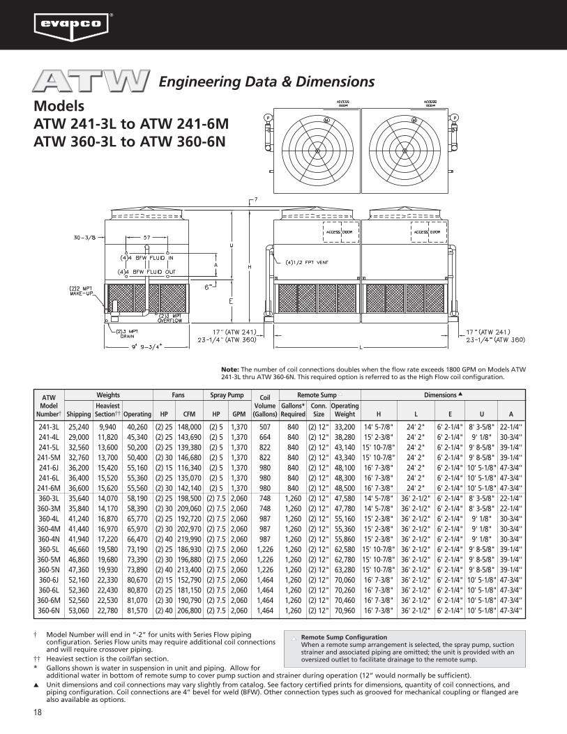
ModelsATW 241-3L to ATW 241-6M ATW 360-3L to ATW 360-6N
Note: The number of coil connections doubles when the flow rate exceeds 1800 GPM on Models ATW241-3L thru ATW 360-6N. This required option is referred to as the High Flow coil configuration.
† Model Number will end in “-2” for units with Series Flow pipingconfiguration. Series Flow units may require additional coil connectionsand will require crossover piping.
†† Heaviest section is the coil/fan section.* Gallons shown is water in suspension in unit and piping. Allow for
additional water in bottom of remote sump to cover pump suction and strainer during operation (12” would normally be sufficient).▲ Unit dimensions and coil connections may vary slightly from catalog. See factory certified prints for dimensions, quantity of coil connections, and
piping configuration. Coil connections are 4” bevel for weld (BFW). Other connection types such as grooved for mechanical coupling or flanged arealso available as options.
▲ Remote Sump ConfigurationWhen a remote sump arrangement is selected, the spray pump, suction strainer and associated piping are omitted; the unit is provided with an oversized outlet to facilitate drainage to the remote sump.
Engineering Data & Dimensions
ATW CoilModel Heaviest Volume Gallons* Conn. Operating
Number† Shipping Section†† Operating HP CFM HP GPM (Gallons) Required Size Weight H L E U A
241-3L 25,240 9,940 40,260 (2) 25 148,000 (2) 5 1,370 507 840 (2) 12" 33,200 14' 5-7/8" 24' 2" 6' 2-1/4" 8' 3-5/8" 22-1/4''241-4L 29,000 11,820 45,340 (2) 25 143,690 (2) 5 1,370 664 840 (2) 12" 38,280 15' 2-3/8" 24' 2" 6' 2-1/4" 9' 1/8" 30-3/4''241-5L 32,560 13,600 50,200 (2) 25 139,380 (2) 5 1,370 822 840 (2) 12" 43,140 15' 10-7/8" 24' 2" 6' 2-1/4" 9' 8-5/8" 39-1/4''241-5M 32,760 13,700 50,400 (2) 30 146,680 (2) 5 1,370 822 840 (2) 12" 43,340 15' 10-7/8" 24' 2" 6' 2-1/4" 9' 8-5/8" 39-1/4''241-6J 36,200 15,420 55,160 (2) 15 116,340 (2) 5 1,370 980 840 (2) 12" 48,100 16' 7-3/8" 24' 2" 6' 2-1/4" 10' 5-1/8" 47-3/4''241-6L 36,400 15,520 55,360 (2) 25 135,070 (2) 5 1,370 980 840 (2) 12" 48,300 16' 7-3/8" 24' 2" 6' 2-1/4" 10' 5-1/8" 47-3/4''241-6M 36,600 15,620 55,560 (2) 30 142,140 (2) 5 1,370 980 840 (2) 12" 48,500 16' 7-3/8" 24' 2" 6' 2-1/4" 10' 5-1/8" 47-3/4''360-3L 35,640 14,070 58,190 (2) 25 198,500 (2) 7.5 2,060 748 1,260 (2) 12" 47,580 14' 5-7/8" 36' 2-1/2" 6' 2-1/4" 8' 3-5/8" 22-1/4''360-3M 35,840 14,170 58,390 (2) 30 209,060 (2) 7.5 2,060 748 1,260 (2) 12" 47,780 14' 5-7/8" 36' 2-1/2" 6' 2-1/4" 8' 3-5/8" 22-1/4''360-4L 41,240 16,870 65,770 (2) 25 192,720 (2) 7.5 2,060 987 1,260 (2) 12" 55,160 15' 2-3/8" 36' 2-1/2" 6' 2-1/4" 9' 1/8" 30-3/4''360-4M 41,440 16,970 65,970 (2) 30 202,970 (2) 7.5 2,060 987 1,260 (2) 12" 55,360 15' 2-3/8" 36' 2-1/2" 6' 2-1/4" 9' 1/8" 30-3/4''360-4N 41,940 17,220 66,470 (2) 40 219,990 (2) 7.5 2,060 987 1,260 (2) 12" 55,860 15' 2-3/8" 36' 2-1/2" 6' 2-1/4" 9' 1/8" 30-3/4''360-5L 46,660 19,580 73,190 (2) 25 186,930 (2) 7.5 2,060 1,226 1,260 (2) 12" 62,580 15' 10-7/8" 36' 2-1/2" 6' 2-1/4" 9' 8-5/8" 39-1/4''360-5M 46,860 19,680 73,390 (2) 30 196,880 (2) 7.5 2,060 1,226 1,260 (2) 12" 62,780 15' 10-7/8" 36' 2-1/2" 6' 2-1/4" 9' 8-5/8" 39-1/4''360-5N 47,360 19,930 73,890 (2) 40 213,400 (2) 7.5 2,060 1,226 1,260 (2) 12" 63,280 15' 10-7/8" 36' 2-1/2" 6' 2-1/4" 9' 8-5/8" 39-1/4''360-6J 52,160 22,330 80,670 (2) 15 152,790 (2) 7.5 2,060 1,464 1,260 (2) 12" 70,060 16' 7-3/8" 36' 2-1/2" 6' 2-1/4" 10' 5-1/8" 47-3/4''360-6L 52,360 22,430 80,870 (2) 25 181,150 (2) 7.5 2,060 1,464 1,260 (2) 12" 70,260 16' 7-3/8" 36' 2-1/2" 6' 2-1/4" 10' 5-1/8" 47-3/4''360-6M 52,560 22,530 81,070 (2) 30 190,790 (2) 7.5 2,060 1,464 1,260 (2) 12" 70,460 16' 7-3/8" 36' 2-1/2" 6' 2-1/4" 10' 5-1/8" 47-3/4''360-6N 53,060 22,780 81,570 (2) 40 206,800 (2) 7.5 2,060 1,464 1,260 (2) 12" 70,960 16' 7-3/8" 36' 2-1/2" 6' 2-1/4" 10' 5-1/8" 47-3/4''
Weights Fans Spray Pump Remote Sump ▲ Dimensions ▲

19
2 MPTMAKE-UP
2 MPTMAKE-UP
ModelsATW 242-3L to ATW 242-6MATW 362-3L to ATW 362-6N
Note: The number of coil connections doubles when the flow rate exceeds 1800 GPM on Models ATW242-3L thru ATW 362-6N. This required option is referred to as the High Flow coil configuration.
Selections for ATW Closed Circuit Coolers are available from EVAPCO’s iES Equipment Selection Program.
Please contact your local sales representative for more information on the iES program.
† Model Number will end in “-2” for units with Series Flow pipingconfiguration. Series Flow units may require additional coil connectionsand will require crossover piping.
†† Heaviest section is the coil/fan section.* Gallons shown is water in suspension in unit and piping. Allow for
additional water in bottom of remote sump to cover pump suction and strainer during operation (12” would normally be sufficient).▲ Unit dimensions and coil connections may vary slightly from catalog. See factory certified prints for dimensions, quantity of coil connections, and
piping configuration. Coil connections are 4” bevel for weld (BFW). Other connection types such as grooved for mechanical coupling or flanged arealso available as options.
▲ Remote Sump ConfigurationWhen a remote sump arrangement is selected, the spray pump, suctionstrainer and associated piping are omitted; the unit is provided with anoversized outlet to facilitate drainage to the remote sump.
Engineering Data & Dimensions
ATW CoilModel Heaviest Volume Gallons* Conn. Operating
Number† Shipping Section†† Operating HP CFM HP GPM (Gallons) Required Size Weight H L E U A
242-3L 25,000 9,940 40,020 (2) 25 148,000 (2) 5 1,370 507 840 (2) 12" 32,960 14' 5-7/8" 11' 11-3/4" 6' 2-1/4" 8' 3-5/8" 22-1/4''242-4L 28,760 11,820 45,100 (2) 25 143,690 (2) 5 1,370 664 840 (2) 12" 38,040 15' 2-3/8" 11' 11-3/4" 6' 2-1/4" 9' 1/8" 30-3/4''242-5L 32,320 13,600 49,960 (2) 25 139,380 (2) 5 1,370 822 840 (2) 12" 42,900 15' 10-7/8" 11' 11-3/4" 6' 2-1/4" 9' 8-5/8" 39-1/4''242-5M 32,520 13,700 50,160 (2) 30 146,680 (2) 5 1,370 822 840 (2) 12" 43,100 15' 10-7/8" 11' 11-3/4" 6' 2-1/4" 9' 8-5/8" 39-1/4''242-6J 35,960 15,420 54,920 (2) 15 116,340 (2) 5 1,370 980 840 (2) 12" 47,860 16' 7-3/8" 11' 11-3/4" 6' 2-1/4" 10' 5-1/8" 47-3/4''242-6L 36,160 15,520 55,120 (2) 25 135,070 (2) 5 1,370 980 840 (2) 12" 48,060 16' 7-3/8" 11' 11-3/4" 6' 2-1/4" 10' 5-1/8" 47-3/4''242-6M 36,360 15,620 55,320 (2) 30 142,140 (2) 5 1,370 980 840 (2) 12" 48,260 16' 7-3/8" 11' 11-3/4" 6' 2-1/4" 10' 5-1/8" 47-3/4''362-3L 35,680 14,070 58,230 (2) 25 198,500 (2) 7.5 2,060 748 1,260 (2) 12" 47,620 15' 5-7/8" 18' 0" 7' 2-1/4" 8' 3-5/8" 22-1/4''362-3M 35,880 14,170 58,430 (2) 30 209,060 (2) 7.5 2,060 748 1,260 (2) 12" 47,820 15' 5-7/8" 18' 0" 7' 2-1/4" 8' 3-5/8" 22-1/4''362-4L 41,280 16,870 65,810 (2) 25 192,710 (2) 7.5 2,060 987 1,260 (2) 12" 55,200 16' 2-3/8" 18' 0" 7' 2-1/4" 9' 1/8" 30-3/4''362-4M 41,480 16,970 66,010 (2) 30 202,970 (2) 7.5 2,060 987 1,260 (2) 12" 55,400 16' 2-3/8" 18' 0" 7' 2-1/4" 9' 1/8" 30-3/4''362-4N 41,980 17,220 66,510 (2) 40 219,990 (2) 7.5 2,060 987 1,260 (2) 12" 55,900 16' 2-3/8" 18' 0" 7' 2-1/4" 9' 1/8" 30-3/4''362-5L 46,700 19,580 73,230 (2) 25 186,930 (2) 7.5 2,060 1,226 1,260 (2) 12" 62,620 16' 10-7/8" 18' 0" 7' 2-1/4" 9' 8-5/8" 39-1/4''362-5M 46,900 19,680 73,430 (2) 30 196,880 (2) 7.5 2,060 1,226 1,260 (2) 12" 62,820 16' 10-7/8" 18' 0" 7' 2-1/4" 9' 8-5/8" 39-1/4''362-5N 47,400 19,930 73,930 (2) 40 213,400 (2) 7.5 2,060 1,226 1,260 (2) 12" 63,320 16' 10-7/8" 18' 0" 7' 2-1/4" 9' 8-5/8" 39-1/4''362-6J 52,200 22,330 80,710 (2) 15 152,790 (2) 7.5 2,060 1,464 1,260 (2) 12" 70,100 17' 7-3/8" 18' 0" 7' 2-1/4" 10' 5-1/8" 47-3/4''362-6L 52,400 22,430 80,910 (2) 25 181,150 (2) 7.5 2,060 1,464 1,260 (2) 12" 70,300 17' 7-3/8" 18' 0" 7' 2-1/4" 10' 5-1/8" 47-3/4''362-6M 52,600 22,530 81,110 (2) 30 190,790 (2) 7.5 2,060 1,464 1,260 (2) 12" 70,500 17' 7-3/8" 18' 0" 7' 2-1/4" 10' 5-1/8" 47-3/4''362-6N 53,100 22,780 81,610 (2) 40 206,800 (2) 7.5 2,060 1,464 1,260 (2) 12" 71,000 17' 7-3/8" 18' 0" 7' 2-1/4" 10' 5-1/8" 47-3/4''
Weights Fans Spray Pump Remote Sump ▲ Dimensions ▲

20
ModelsATW 144-3K to ATW 144-6NATW 168-3L to ATW 168-6N
Note: The number of coil connections doubles when the flow rate exceeds 900 GPM on Models ATW144-3K thru ATW 168-6N. This required option is referred to as the High Flow coil configuration.
Engineering Data & Dimensions
† Model Number will end in “-2” for units with Series Flow pipingconfiguration. Series Flow units may require additional coilconnections and will require crossover piping.
†† Heaviest section is the coil/fan section.* Gallons shown is water in suspension in unit and piping. Allow for
additional water in bottom of remote sump to cover pump suction and strainer during operation (12” would normally be sufficient).▲ Unit dimensions and coil connections may vary slightly from catalog. See factory certified prints for dimensions, quantity of coil connections,
and piping configuration. Coil connections are 4” bevel for weld (BFW). Other connection types such as grooved for mechanical coupling orflanged are also available as options.
▲ Remote Sump ConfigurationWhen a remote sump arrangement is selected, the spray pump, suction strainer and associated piping are omitted; the unit is provided with an oversized outlet to facilitate drainage to the remote sump.
ATW CoilModel Heaviest Volume Gallons* Conn. Operating
Number† Shipping Section†† Operating HP CFM HP GPM (Gallons) Required Size Weight H L E U A
144-3K 14,200 11,630 22,820 20 79,800 5 800 312 490 12" 18,910 13' 5-7/8" 11' 11-3/4 " 5' 2-1/4" 8' 3-5/8" 22-1/4''144-3L 14,250 11,680 22,870 25 85,040 5 800 312 490 12" 18,960 13' 5-7/8" 11' 11-3/4 " 5' 2-1/4" 8' 3-5/8" 22-1/4''144-4K 16,480 13,910 25,920 20 77,470 5 800 409 490 12" 22,010 14' 2-3/8" 11' 11-3/4 " 5' 2-1/4" 9' 1/8" 30-3/4''144-4L 16,530 13,960 25,970 25 82,560 5 800 409 490 12" 22,060 14' 2-3/8" 11' 11-3/4 " 5' 2-1/4" 9' 1/8" 30-3/4''144-4M 16,630 14,060 26,070 30 86,890 5 800 409 490 12" 22,160 14' 2-3/8" 11' 11-3/4 " 5' 2-1/4" 9' 1/8" 30-3/4''144-5L 18,710 16,140 28,960 25 80,090 5 800 506 490 12" 25,050 14' 10-7/8" 11' 11-3/4 " 5' 2-1/4" 9' 8-5/8" 39-1/4''144-5M 18,810 16,240 29,060 30 84,280 5 800 506 490 12" 25,150 14' 10-7/8" 11' 11-3/4 " 5' 2-1/4" 9' 8-5/8" 39-1/4''144-6M 21,170 18,600 32,230 30 81,680 5 800 604 490 12" 28,320 15' 7-3/8" 11' 11-3/4 " 5' 2-1/4" 10' 5-1/8" 47-3/4''144-6N 21,420 18,850 32,480 40 88,530 5 800 604 490 12" 28,570 15' 7-3/8" 11' 11-3/4 " 5' 2-1/4" 10' 5-1/8" 47-3/4''168-3L 16,100 13,180 26,220 25 95,050 5 900 361 570 12" 21,690 13' 11-7/8" 13' 11-3/4 " 5' 8-1/4" 8' 3-5/8" 22-1/4''168-3M 16,170 13,250 26,290 30 100,030 5 900 361 570 12" 21,760 13' 11-7/8" 13' 11-3/4 " 5' 8-1/4" 8' 3-5/8" 22-1/4''168-4L 18,790 15,870 29,860 25 92,280 5 900 475 570 12" 25,330 14' 8-3/8" 13' 11-3/4 " 5' 8-1/4" 9' 1/8" 30-3/4''168-4M 18,860 15,940 29,930 30 97,110 5 900 475 570 12" 25,400 14' 8-3/8" 13' 11-3/4 " 5' 8-1/4" 9' 1/8" 30-3/4''168-5M 21,360 18,440 33,380 30 94,200 5 900 589 570 12" 28,850 15' 4-7/8" 13' 11-3/4 " 5' 8-1/4" 9' 8-5/8" 39-1/4''168-5N 21,620 18,700 33,640 40 102,100 5 900 589 570 12" 29,110 15' 4-7/8" 13' 11-3/4 " 5' 8-1/4" 9' 8-5/8" 39-1/4''168-6M 24,360 21,440 37,330 30 91,290 5 900 703 570 12" 32,800 16' 1-3/8" 13' 11-3/4 " 5' 8-1/4" 10' 5-1/8" 47-3/4''168-6N 24,620 21,700 37,590 40 98,940 5 900 703 570 12" 33,060 16' 1-3/8" 13' 11-3/4 " 5' 8-1/4" 10' 5-1/8" 47-3/4''
Weights Fans Spray Pump Remote Sump ▲ Dimensions ▲

21
ModelsATW 216-3L to ATW 216-6OATW 240-3M to ATW 240-6P
Note: The number of coil connections doubles when the flow rate exceeds 900 GPM on Models ATW216-3L thru ATW 240-6P. This required option is referred to as the High Flow coil configuration.
Selections for ATW Closed Circuit Coolers are available from EVAPCO’s iES Equipment Selection Program.
Please contact your local sales representative for more information on the iES program.
Engineering Data & Dimensions
† Model Number will end in “-2” for units with Series Flow pipingconfiguration. Series Flow units may require additional coil connectionsand will require crossover piping.
†† Heaviest section is the coil/fan section.* Gallons shown is water in suspension in unit and piping. Allow for
additional water in bottom of remote sump to cover pump suction and strainer during operation (12” would normally be sufficient).▲ Unit dimensions and coil connections may vary slightly from catalog. See factory certified prints for dimensions, quantity of coil connections, and
piping configuration. Coil connections are 4” bevel for weld (BFW). Other connection types such as grooved for mechanical coupling or flanged are also available as options.
▲ Remote Sump ConfigurationWhen a remote sump arrangement is selected, the spray pump, suction strainer and associated piping are omitted; the unit is provided with an oversized outlet to facilitate drainage to the remote sump.
ATW CoilModel Heaviest Volume Gallons* Conn. Operating
Number† Shipping Section†† Operating HP CFM HP GPM (Gallons) Required Size Weight H L E U A
216-3L 20,200 16,400 33,140 25 116,390 7.5 1,200 461 720 12" 27,230 14' 5-7/8" 18' 0" 6' 2-1/4" 8' 3-5/8" 22-1/4''216-3M 20,310 16,510 33,250 30 123,680 7.5 1,200 461 720 12" 27,340 14' 5-7/8" 18' 0" 6' 2-1/4" 8' 3-5/8" 22-1/4''216-4L 23,630 19,830 37,800 25 113,000 7.5 1,200 608 720 12" 31,890 15' 2-3/8" 18' 0" 6' 2-1/4" 9' 1/8" 30-3/4''216-4M 23,740 19,940 37,910 30 120,070 7.5 1,200 608 720 12" 32,000 15' 2-3/8" 18' 0" 6' 2-1/4" 9' 1/8" 30-3/4''216-4N 24,000 20,200 38,170 40 130,320 7.5 1,200 608 720 12" 32,260 15' 2-3/8" 18' 0" 6' 2-1/4" 9' 1/8" 30-3/4''216-5M 27,040 23,240 42,430 30 116,470 7.5 1,200 755 720 12" 36,520 15' 10-7/8" 18' 0" 6' 2-1/4" 9' 8-5/8" 39-1/4''216-5N 27,300 23,500 42,690 40 126,410 7.5 1,200 755 720 12" 36,780 15' 10-7/8" 18' 0" 6' 2-1/4" 9' 8-5/8" 39-1/4''216-6N 30,690 26,890 47,310 40 122,500 7.5 1,200 902 720 12" 41,400 16' 7-3/8" 18' 0" 6' 2-1/4" 10' 5-1/8" 47-3/4''216-6O 30,750 26,950 47,370 50 130,400 7.5 1,200 902 720 12" 41,460 16' 7-3/8" 18' 0" 6' 2-1/4" 10' 5-1/8" 47-3/4''240-3M 22,410 18,110 36,880 30 132,680 10 1,400 511 800 14" 30,110 14' 5-7/8" 20' 0" 6' 2-1/4" 8' 3-5/8" 22-1/4''240-3N 22,670 18,370 37,140 40 144,810 10 1,400 511 800 14" 30,370 14' 5-7/8" 20' 0" 6' 2-1/4" 8' 3-5/8" 22-1/4''240-4M 26,190 21,890 42,030 30 128,820 10 1,400 674 800 14" 35,260 15' 2-3/8" 20' 0" 6' 2-1/4" 9' 1/8" 30-3/4''240-4N 26,450 22,150 42,290 40 140,600 10 1,400 674 800 14" 35,520 15' 2-3/8" 20' 0" 6' 2-1/4" 9' 1/8" 30-3/4''240-5N 30,130 25,830 47,340 40 136,380 10 1,400 838 800 14" 40,570 15' 10-7/8" 20' 0" 6' 2-1/4" 9' 8-5/8" 39-1/4''240-5O 30,190 25,890 47,400 50 145,170 10 1,400 838 800 14" 40,630 15' 10-7/8" 20' 0" 6' 2-1/4" 9' 8-5/8" 39-1/4''240-6O 34,340 30,040 52,910 50 140,680 10 1,400 1,002 800 14" 46,140 16' 7-3/8" 20' 0" 6' 2-1/4" 10' 5-1/8" 47-3/4''240-6P 34,450 30,150 53,020 60 148,050 10 1,400 1,002 800 14" 46,250 16' 7-3/8" 20' 0" 6' 2-1/4" 10' 5-1/8" 47-3/4''
Weights Fans Spray Pump Remote Sump ▲ Dimensions ▲

22
Engineering Data & Dimensions
ModelsATW 286-3K to ATW 286-6NATW 334-3L to ATW 334-6N
Note: The number of coil connections doubles when the flow rate exceeds 1,800 GPM on Models ATW286-3K thru ATW 334-6N. This required option is referred to as the High Flow coil configuration.
† Model Number will end in “-2” for units with Series Flow pipingconfiguration. Series Flow units may require additional coilconnections and will require crossover piping.
†† Heaviest section is the coil/fan section.* Gallons shown is water in suspension in unit and piping. Allow for
additional water in bottom of remote sump to cover pump suction and strainer during operation (12” would normally be sufficient).▲ Unit dimensions and coil connections may vary slightly from catalog. See factory certified prints for dimensions, quantity of coil connections,
and piping configuration. Coil connections are 4” bevel for weld (BFW). Other connection types such as grooved for mechanical coupling orflanged are also available as options.
▲ Remote Sump ConfigurationWhen a remote sump arrangement is selected, the spray pump, suction strainer and associated piping are omitted; the unit is provided with an oversized outlet to facilitate drainage to the remote sump.
ATW CoilModel Heaviest Volume Gallons* Conn. Operating
Number† Shipping Section†† Operating HP CFM HP GPM (Gallons) Required Size Weight H L E U A
286-3K 28,400 11,630 45,640 (2) 20 159,590 (2) 5 1,600 623 980 (2) 12" 37,820 14' 5-7/8" 24' 2" 6' 2-1/4" 8' 3-5/8" 22-1/4''286-3L 28,500 11,680 45,740 (2) 25 170,080 (2) 5 1,600 623 980 (2) 12" 37,920 14' 5-7/8" 24' 2" 6' 2-1/4" 8'-3-5/8" 22-1/4''286-4L 33,060 13,960 51,930 (2) 25 165,130 (2) 5 1,600 818 980 (2) 12" 44,110 15' 2-3/8" 24' 2" 6' 2-1/4" 9' 1/8" 30-3/4''286-4M 33,260 14,060 52,130 (2) 30 173,780 (2) 5 1,600 818 980 (2) 12" 44,310 15' 2-3/8" 24' 2" 6' 2-1/4" 9' 1/8" 30-3/4''286-5L 37,420 16,140 57,910 (2) 25 160,170 (2) 5 1,600 1,013 980 (2) 12" 50,090 15' 10-7/8" 24' 2" 6' 2-1/4" 9' 8-5/8" 39-1/4''286-5M 37,620 16,240 58,110 (2) 30 168,560 (2) 5 1,600 1,013 980 (2) 12" 50,290 15' 10-7/8" 24' 2" 6' 2-1/4" 9' 8-5/8" 39-1/4''286-6M 42,340 18,600 64,460 (2) 30 163,350 (2) 5 1,600 1,208 980 (2) 12" 56,640 16' 7-3/8" 24' 2" 6' 2-1/4" 10' 5-1/8" 47-3/4''286-6N 42,840 18,850 64,960 (2) 40 177,050 (2) 5 1,600 1,208 980 (2) 12" 57,140 16' 7-3/8" 24' 2" 6' 2-1/4" 10' 5-1/8" 47-3/4''334-3L 32,200 13,180 52,430 (2) 25 190,090 (2) 5 1,800 723 1,140 (2) 12" 43,370 15' 5-7/8" 28' 2" 7' 2-1/4" 8' 3-5/8" 22-1/4''334-3M 32,340 13,250 52,570 (2) 30 200,050 (2) 5 1,800 723 1,140 (2) 12" 43,510 15' 5-7/8" 28' 2" 7' 2-1/4" 8' 3-5/8" 22-1/4''334-4L 37,580 15,870 59,720 (2) 25 184,560 (2) 5 1,800 951 1,140 (2) 12" 50,660 16' 2-3/8" 28' 2" 7' 2-1/4" 9' 1/8" 30-3/4''334-4M 37,720 15,940 59,860 (2) 30 194,220 (2) 5 1,800 951 1,140 (2) 12" 50,800 16' 2-3/8" 28' 2" 7' 2-1/4" 9' 1/8" 30-3/4''334-5M 42,720 18,440 66,760 (2) 30 188,400 (2) 5 1,800 1,179 1,140 (2) 12" 57,700 16' 10-7/8" 28' 2" 7' 2-1/4" 9' 8-5/8" 39-1/4''334-5N 43,240 18,700 67,280 (2) 40 204,200 (2) 5 1,800 1,179 1,140 (2) 12" 58,220 16' 10-7/8" 28' 2" 7' 2-1/4" 9' 8-5/8" 39-1/4''334-6M 48,720 21,440 74,660 (2) 30 182,570 (2) 5 1,800 1,407 1,140 (2) 12" 65,600 17' 7-3/8" 28' 2" 7' 2-1/4" 10' 5-1/8" 47-3/4''334-6N 49,240 21,700 75,180 (2) 40 197,880 (2) 5 1,800 1,407 1,140 (2) 12" 66,120 17' 7-3/8" 28' 2" 7' 2-1/4" 10' 5-1/8" 47-3/4''
Weights Fans Spray Pump Remote Sump ▲ Dimensions ▲

23
Engineering Data & Dimensions
ModelsATW 430-3L to ATW 430-6OATW 478-3M to ATW 478-6P
Note: The number of coil connections doubles when the flow rate exceeds 1,800 GPM on Models ATW430-3L thru ATW 478-6P. This required option is referred to as the High Flow coil configuration.
Selections for ATW Closed Circuit Coolers are available from EVAPCO’s iES Equipment Selection Program.
Please contact your local sales representative for more information on the iES program.
† Model Number will end in “-2” for units with Series Flow pipingconfiguration. Series Flow units may require additional coil connectionsand will require crossover piping.
†† Heaviest section is the coil/fan section.* Gallons shown is water in suspension in unit and piping. Allow for
additional water in bottom of remote sump to cover pump suction and strainer during operation (12” would normally be sufficient).▲ Unit dimensions and coil connections may vary slightly from catalog. See factory certified prints for dimensions, quantity of coil connections, and
piping configuration. Coil connections are 4” bevel for weld (BFW). Other connection types such as grooved for mechanical coupling or flanged are also available as options.
▲ Remote Sump ConfigurationWhen a remote sump arrangement is selected, the spray pump, suction strainer and associated piping are omitted; the unit is provided with an oversized outlet to facilitate drainage to the remote sump.
ATW CoilModel Heaviest Volume Gallons* Conn. Operating
Number† Shipping Section†† Operating HP CFM HP GPM (Gallons) Required Size Weight H L E U A
430-3L 40,400 16,400 66,270 (2) 25 232,770 (2) 7.5 2,400 922 1,440 (2) 12" 54,450 15' 5-7/8" 36' 2-1/2" 7' 2-1/4" 8' 3-5/8" 22-1/4''430-3M 40,620 16,510 66,490 (2) 30 247,350 (2) 7.5 2,400 922 1,440 (2) 12" 54,670 15' 5-7/8" 36' 2-1/2" 7' 2-1/4" 8' 3-5/8" 22-1/4''430-4L 47,260 19,830 75,590 (2) 25 225,990 (2) 7.5 2,400 1,216 1,440 (2) 12" 63,770 16' 2-3/8" 36' 2-1/2" 7' 2-1/4" 9' 1/8" 30-3/4''430-4M 47,480 19,940 75,810 (2) 30 240,150 (2) 7.5 2,400 1,216 1,440 (2) 12" 63,990 16' 2-3/8" 36' 2-1/2" 7' 2-1/4" 9' 1/8" 30-3/4''430-4N 48,000 20,200 76,330 (2) 40 260,630 (2) 7.5 2,400 1,216 1,440 (2) 12" 64,510 16' 2-3/8" 36' 2-1/2" 7' 2-1/4" 9' 1/8" 30-3/4''430-5M 54,080 23,240 84,860 (2) 30 232,940 (2) 7.5 2,400 1,510 1,440 (2) 12" 73,040 16' 10-7/8" 36' 2-1/2" 7' 2-1/4" 9' 8-5/8" 39-1/4''430-5N 54,600 23,500 85,380 (2) 40 252,810 (2) 7.5 2,400 1,510 1,440 (2) 12" 73,560 16' 10-7/8" 36' 2-1/2" 7' 2-1/4" 9' 8-5/8" 39-1/4''430-6N 61,380 26,890 94,620 (2) 40 244,990 (2) 7.5 2,400 1,805 1,440 (2) 12" 82,800 17' 7-3/8" 36' 2-1/2" 7' 2-1/4" 10' 5-1/8" 47-3/4''430-6O 61,500 26,950 94,740 (2) 50 260,790 (2) 7.5 2,400 1,805 1,440 (2) 12" 82,920 17' 7-3/8" 36' 2-1/2" 7' 2-1/4" 10' 5-1/8" 47-3/4''478-3M 44,820 18,110 73,760 (2) 30 265,370 (2) 10 2,800 1,021 1,600 (2) 14" 60,220 15' 5-7/8" 40' 2-1/2" 7' 2-1/4" 8' 3-5/8" 22-1/4''478-3N 45,340 18,370 74,280 (2) 40 289,630 (2) 10 2,800 1,021 1,600 (2) 14" 60,740 15' 5-7/8" 40' 2-1/2" 7' 2-1/4" 8' 3-5/8" 22-1/4''478-4M 52,380 21,890 84,060 (2) 30 257,640 (2) 10 2,800 1,349 1,600 (2) 14" 70,520 16' 2-3/8" 40' 2-1/2" 7' 2-1/4" 9' 1/8" 30-3/4''478-4N 52,900 22,150 84,580 (2) 40 281,190 (2) 10 2,800 1,349 1,600 (2) 14" 71,040 16' 2-3/8" 40' 2-1/2" 7' 2-1/4" 9' 1/8" 30-3/4''478-5N 60,260 25,830 94,670 (2) 40 272,750 (2) 10 2,800 1,676 1,600 (2) 14" 81,130 16' 10-7/8" 40' 2-1/2" 7' 2-1/4" 9' 8-5/8" 39-1/4''478-5O 60,380 25,890 94,790 (2) 50 290,340 (2) 10 2,800 1,676 1,600 (2) 14" 81,250 16' 10-7/8" 40' 2-1/2" 7' 2-1/4" 9' 8-5/8" 39-1/4''478-6O 68,680 30,040 105,820 (2) 50 281,360 (2) 10 2,800 2,004 1,600 (2) 14" 92,280 17' 7-3/8" 40' 2-1/2" 7' 2-1/4" 10' 5-1/8" 47-3/4''478-6P 68,900 30,150 106,040 (2) 60 296,090 (2) 10 2,800 2,004 1,600 (2) 14" 92,500 17' 7-3/8" 40' 2-1/2" 7' 2-1/4" 10' 5-1/8" 47-3/4''
Weights Fans Spray Pump Remote Sump ▲ Dimensions ▲

24
Engineering Data & Dimensions
ModelsATW 290-3K to ATW 290-6NATW 338-3L to ATW 338-6N
Note: The number of coil connections doubles when the flow rate exceeds 1,800 GPM on Models ATW290-3K thru ATW 338-6N. This required option is referred to as the High Flow coil configuration.
† Model Number will end in “-2” for units with Series Flow pipingconfiguration. Series Flow units may require additional coilconnections and will require crossover piping.
†† Heaviest section is the coil/fan section.* Gallons shown is water in suspension in unit and piping. Allow for
additional water in bottom of remote sump to cover pump suction and strainer during operation (12” would normally be sufficient).▲ Unit dimensions and coil connections may vary slightly from catalog. See factory certified prints for dimensions, quantity of coil connections,
and piping configuration. Coil connections are 4” bevel for weld (BFW). Other connection types such as grooved for mechanical coupling orflanged are also available as options.
▲ Remote Sump ConfigurationWhen a remote sump arrangement is selected, the spray pump, suction strainer and associated piping are omitted; the unit is provided with an oversized outlet to facilitate drainage to the remote sump.
ATW CoilModel Heaviest Volume Gallons* Conn. Operating
Number† Shipping Section†† Operating HP CFM HP GPM (Gallons) Required Size Weight H L E U A
290-3K 28,400 11,630 45,640 (2) 20 159,590 (2) 5 1,600 623 980 (2) 12" 37,820 14' 5-7/8" 11' 11-3/4 " 6' 2-1/4" 8' 3-5/8" 22-1/4''290-3L 28,500 11,680 45,740 (2) 25 170,080 (2) 5 1,600 623 980 (2) 12" 37,920 14' 5-7/8" 11' 11-3/4 " 6' 2-1/4" 8' 3-5/8" 22-1/4''290-4L 33,060 13,960 51,930 (2) 25 165,130 (2) 5 1,600 818 980 (2) 12" 44,110 15' 2-3/8" 11' 11-3/4 " 6' 2-1/4" 9' 1/8" 30-3/4''290-4M 33,260 14,060 52,130 (2) 30 173,780 (2) 5 1,600 818 980 (2) 12" 44,310 15' 2-3/8" 11' 11-3/4 " 6' 2-1/4" 9' 1/8" 30-3/4''290-5L 37,420 16,140 57,910 (2) 25 160,170 (2) 5 1,600 1,013 980 (2) 12" 50,090 15' 10-7/8" 11' 11-3/4 " 6' 2-1/4" 9' 8-5/8" 39-1/4''290-5M 37,620 16,240 58,110 (2) 30 168,560 (2) 5 1,600 1,013 980 (2) 12" 50,290 15' 10-7/8" 11' 11-3/4 " 6' 2-1/4" 9' 8-5/8" 39-1/4''290-6M 42,340 18,600 64,460 (2) 30 163,350 (2) 5 1,600 1,208 980 (2) 12" 56,640 16' 7-3/8" 11' 11-3/4 " 6' 2-1/4" 10' 5-1/8" 47-3/4''290-6N 42,840 18,850 64,960 (2) 40 177,050 (2) 5 1,600 1,208 980 (2) 12" 57,140 16' 7-3/8" 11' 11-3/4 " 6' 2-1/4" 10' 5-1/8" 47-3/4''338-3L 32,200 13,180 52,430 (2) 25 190,090 (2) 5 1,800 723 1,140 (2) 12" 43,370 15' 5-7/8" 13' 11-3/4 " 7' 2-1/4" 8' 3-5/8" 22-1/4''338-3M 32,340 13,250 52,570 (2) 30 200,050 (2) 5 1,800 723 1,140 (2) 12" 43,510 15' 5-7/8" 13' 11-3/4 " 7' 2-1/4" 8' 3-5/8" 22-1/4''338-4L 37,580 15,870 59,720 (2) 25 184,560 (2) 5 1,800 951 1,140 (2) 12" 50,660 16' 2-3/8" 13' 11-3/4 " 7' 2-1/4" 9' 1/8" 30-3/4''338-4M 37,720 15,940 59,860 (2) 30 194,220 (2) 5 1,800 951 1,140 (2) 12" 50,800 16' 2-3/8" 13' 11-3/4 " 7' 2-1/4" 9' 1/8" 30-3/4''338-5M 42,720 18,440 66,760 (2) 30 188,400 (2) 5 1,800 1,179 1,140 (2) 12" 57,700 16' 10-7/8" 13' 11-3/4 " 7' 2-1/4" 9' 8-5/8" 39-1/4''338-5N 43,240 18,700 67,280 (2) 40 204,200 (2) 5 1,800 1,179 1,140 (2) 12" 58,220 16' 10-7/8" 13' 11-3/4 " 7' 2-1/4" 9' 8-5/8" 39-1/4''338-6M 48,720 21,440 74,660 (2) 30 182,570 (2) 5 1,800 1,407 1,140 (2) 12" 65,600 17' 7-3/8" 13' 11-3/4 " 7' 2-1/4" 10' 5-1/8" 47-3/4''338-6N 49,240 21,700 75,180 (2) 40 197,880 (2) 5 1,800 1,407 1,140 (2) 12" 66,120 17' 7-3/8" 13' 11-3/4 " 7' 2-1/4" 10' 5-1/8" 47-3/4''
Weights Fans Spray Pump Remote Sump ▲ Dimensions ▲

25
Note: The number of coil connections doubles when the flow rate exceeds 1,800 GPM on Models ATW434-3L thru ATW 482-6P. This required option is referred to as the High Flow coil configuration.
Selections for ATW Closed Circuit Coolers are available from EVAPCO’s iES Equipment Selection Program.
Please contact your local sales representative for more information on the iES program.
Engineering Data & Dimensions
ModelsATW 434-3L to ATW 434-6OATW 482-3M to ATW 482-6P
† Model Number will end in “-2” for units with Series Flow pipingconfiguration. Series Flow units may require additional coil connectionsand will require crossover piping.
†† Heaviest section is the coil/fan section.* Gallons shown is water in suspension in unit and piping. Allow for
additional water in bottom of remote sump to cover pump suction and strainer during operation (12” would normally be sufficient).▲ Unit dimensions and coil connections may vary slightly from catalog. See factory certified prints for dimensions, quantity of coil connections, and
piping configuration. Coil connections are 4” bevel for weld (BFW). Other connection types such as grooved for mechanical coupling or flanged are also available as options.
▲ Remote Sump ConfigurationWhen a remote sump arrangement is selected, the spray pump, suction strainer and associated piping are omitted; the unit is provided with an oversized outlet to facilitate drainage to the remote sump.
ATW CoilModel Heaviest Volume Gallons* Conn. Operating
Number† Shipping Section†† Operating HP CFM HP GPM (Gallons) Required Size Weight H L E U A
434-3L 40,400 16,400 66,270 (2) 25 232,770 (2) 7.5 2,400 922 1,440 (2) 12" 54,450 16' 5-7/8" 18' 0" 8' 2-1/4" 8' 3-5/8" 22-1/4''434-3M 40,620 16,510 66,490 (2) 30 247,350 (2) 7.5 2,400 922 1,440 (2) 12" 54,670 16' 5-7/8" 18' 0" 8' 2-1/4" 8' 3-5/8" 22-1/4''434-4L 47,260 19,830 75,590 (2) 25 225,990 (2) 7.5 2,400 1,216 1,440 (2) 12" 63,770 17' 2-3/8" 18' 0" 8' 2-1/4" 9' 1/8" 30-3/4''434-4M 47,480 19,940 75,810 (2) 30 240,150 (2) 7.5 2,400 1,216 1,440 (2) 12" 63,990 17' 2-3/8" 18' 0" 8' 2-1/4" 9' 1/8" 30-3/4''434-4N 48,000 20,200 76,330 (2) 40 260,630 (2) 7.5 2,400 1,216 1,440 (2) 12" 64,510 17' 2-3/8" 18' 0" 8' 2-1/4" 9' 1/8" 30-3/4''434-5M 54,080 23,240 84,860 (2) 30 232,940 (2) 7.5 2,400 1,510 1,440 (2) 12" 73,040 17' 10-7/8" 18' 0" 8' 2-1/4" 9' 8-5/8" 39-1/4''434-5N 54,600 23,500 85,380 (2) 40 252,810 (2) 7.5 2,400 1,510 1,440 (2) 12" 73,560 17' 10-7/8" 18' 0" 8' 2-1/4" 9' 8-5/8" 39-1/4''434-6N 61,380 26,890 94,620 (2) 40 244,990 (2) 7.5 2,400 1,805 1,440 (2) 12" 82,800 18' 7-3/8" 18' 0" 8' 2-1/4" 10' 5-1/8" 47-3/4''434-6O 61,500 26,950 94,740 (2) 50 260,790 (2) 7.5 2,400 1,805 1,440 (2) 12" 82,920 18' 7-3/8" 18' 0" 8' 2-1/4" 10' 5-1/8" 47-3/4''482-3M 44,820 18,110 73,760 (2) 30 265,370 (2) 10 2,800 1,021 1,600 (2) 14" 60,220 16' 5-7/8" 20' 0" 8' 2-1/4" 8' 3-5/8" 22-1/4''482-3N 45,340 18,370 74,280 (2) 40 289,630 (2) 10 2,800 1,021 1,600 (2) 14" 60,740 16' 5-7/8" 20' 0" 8' 2-1/4" 8' 3-5/8" 22-1/4''482-4M 52,380 21,890 84,060 (2) 30 257,640 (2) 10 2,800 1,349 1,600 (2) 14" 70,520 17' 2-3/8" 20' 0" 8' 2-1/4" 9' 1/8" 30-3/4''482-4N 52,900 22,150 84,580 (2) 40 281,190 (2) 10 2,800 1,349 1,600 (2) 14" 71,040 17' 2-3/8" 20' 0" 8' 2-1/4" 9' 1/8" 30-3/4''482-5N 60,260 25,830 94,670 (2) 40 272,750 (2) 10 2,800 1,676 1,600 (2) 14" 81,130 17' 10-7/8" 20' 0" 8' 2-1/4" 9' 8-5/8" 39-1/4''482-5O 60,380 25,890 94,790 (2) 50 290,340 (2) 10 2,800 1,676 1,600 (2) 14" 81,250 17' 10-7/8" 20' 0" 8' 2-1/4" 9' 8-5/8" 39-1/4''482-6O 68,680 30,040 105,820 (2) 50 281,360 (2) 10 2,800 2,004 1,600 (2) 14" 92,280 18' 7-3/8" 20' 0" 8' 2-1/4" 10' 5-1/8" 47-3/4''482-6P 68,900 30,150 106,040 (2) 60 296,090 (2) 10 2,800 2,004 1,600 (2) 14" 92,500 18' 7-3/8" 20' 0" 8' 2-1/4" 10' 5-1/8" 47-3/4''
Weights Fans Spray Pump Remote Sump ▲ Dimensions ▲

26
Engineering Data & Dimensions
ModelsATW 578-3K to ATW 578-6NATW 672-3L to ATW 672-6N
Note: The number of coil connections doubles when the flow rate exceeds 3,600 GPM on Models ATW578-3K thru ATW 672-6N. This required option is referred to as the High Flow coil configuration.
† Model Number will end in “-2” for units with Series Flow pipingconfiguration. Series Flow units may require additional coilconnections and will require crossover piping.
†† Heaviest section is the coil/fan section.* Gallons shown is water in suspension in unit and piping. Allow for
additional water in bottom of remote sump to cover pump suction and strainer during operation (12” would normally be sufficient).▲ Unit dimensions and coil connections may vary slightly from catalog. See factory certified prints for dimensions, quantity of coil connections,
and piping configuration. Coil connections are 4” bevel for weld (BFW). Other connection types such as grooved for mechanical coupling orflanged are also available as options.
▲ Remote Sump ConfigurationWhen a remote sump arrangement is selected, the spray pump, suction strainer and associated piping are omitted; the unit is provided with an oversized outlet to facilitate drainage to the remote sump.
ATW CoilModel Heaviest Volume Gallons* Conn. Operating
Number† Shipping Section†† Operating HP CFM HP GPM (Gallons) Required Size Weight H L E U A
578-3K 57,320 11,630 91,280 (4) 20 319,180 (4) 5 3,200 1,246 1,960 (4) 12" 75,640 16' 5-7/8" 24' 2" 8' 2-1/4" 8' 3-5/8" 22-1/4''578-3L 57,520 11,680 91,480 (4) 25 340,160 (4) 5 3,200 1,246 1,960 (4) 12" 75,840 16' 5-7/8" 24' 2" 8' 2-1/4" 8' 3-5/8" 22-1/4''578-4K 66,440 13,910 103,650 (4) 20 309,880 (4) 5 3,200 1,636 1,960 (4) 12" 88,010 17' 2-3/8" 24' 2" 8' 2-1/4" 9' 1/8" 30-3/4''578-4L 66,640 13,960 103,850 (4) 25 330,260 (4) 5 3,200 1,636 1,960 (4) 12" 88,210 17' 2-3/8" 24' 2" 8' 2-1/4" 9' 1/8" 30-3/4''578-4M 67,040 14,060 104,250 (4) 30 347,550 (4) 5 3,200 1,636 1,960 (4) 12" 88,610 17' 2-3/8" 24' 2" 8' 2-1/4" 9' 1/8" 30-3/4''578-5L 75,360 16,140 115,820 (4) 25 320,350 (4) 5 3,200 2,026 1,960 (4) 12" 100,180 17' 10-7/8" 24' 2" 8' 2-1/4" 9' 8-5/8" 39-1/4''578-5M 75,760 16,240 116,220 (4) 30 337,130 (4) 5 3,200 2,026 1,960 (4) 12" 100,580 17' 10-7/8" 24' 2" 8' 2-1/4" 9' 8-5/8" 39-1/4''578-6M 85,200 18,600 128,920 (4) 30 326,700 (4) 5 3,200 2,415 1,960 (4) 12" 113,280 18' 7-3/8" 24' 2" 8' 2-1/4" 10' 5-1/8" 47-3/4''578-6N 86,200 18,850 129,920 (4) 40 354,100 (4) 5 3,200 2,415 1,960 (4) 12" 114,280 18' 7-3/8" 24' 2" 8' 2-1/4" 10' 5-1/8" 47-3/4''672-3L 64,820 13,180 104,860 (4) 25 380,190 (4) 5 3,600 1,445 2,280 (4) 12" 86,740 16' 5-7/8" 28' 2" 8' 2-1/4" 8' 3-5/8" 22-1/4''672-3M 65,100 13,250 105,140 (4) 30 400,100 (4) 5 3,600 1,445 2,280 (4) 12" 87,020 16' 5-7/8" 28' 2" 8' 2-1/4" 8' 3-5/8" 22-1/4''672-4L 75,580 15,870 119,430 (4) 25 369,110 (4) 5 3,600 1,901 2,280 (4) 12" 101,310 17' 2-3/8" 28' 2" 8' 2-1/4" 9' 1/8" 30-3/4''672-4M 75,860 15,940 119,710 (4) 30 388,440 (4) 5 3,600 1,901 2,280 (4) 12" 101,590 17' 2-3/8" 28' 2" 8' 2-1/4" 9' 1/8" 30-3/4''672-5M 85,860 18,440 133,510 (4) 30 376,790 (4) 5 3,600 2,357 2,280 (4) 12" 115,390 17' 10-7/8" 28' 2" 8' 2-1/4" 9' 8-5/8" 39-1/4''672-5N 86,900 18,700 134,550 (4) 40 408,400 (4) 5 3,600 2,357 2,280 (4) 12" 116,430 17' 10-7/8" 28' 2" 8' 2-1/4" 9' 8-5/8" 39-1/4''672-6M 97,860 21,440 149,320 (4) 30 365,140 (4) 5 3,600 2,813 2,280 (4) 12" 131,200 18' 7-3/8" 28' 2" 8' 2-1/4" 10' 5-1/8" 47-3/4''672-6N 98,900 21,700 150,360 (4) 40 395,770 (4) 5 3,600 2,813 2,280 (4) 12" 132,240 18' 7-3/8" 28' 2" 8' 2-1/4" 10' 5-1/8" 47-3/4''
Weights Fans Spray Pump Remote Sump ▲ Dimensions ▲

27
Engineering Data & Dimensions
Note: The number of coil connections doubles when the flow rate exceeds 3,600 GPM on Models ATW866-3L thru ATW 960-6P. This required option is referred to as the High Flow coil configuration.
Selections for ATW Closed Circuit Coolers are available from EVAPCO’s iES Equipment Selection Program.
Please contact your local sales representative for more information on the iES program.
ModelsATW 866-3L to ATW 866-6OATW 960-3M to ATW 960-6P
† Model Number will end in “-2” for units with Series Flow pipingconfiguration. Series Flow units may require additional coil connectionsand will require crossover piping.
†† Heaviest section is the coil/fan section.* Gallons shown is water in suspension in unit and piping. Allow for
additional water in bottom of remote sump to cover pump suction and strainer during operation (12” would normally be sufficient).▲ Unit dimensions and coil connections may vary slightly from catalog. See factory certified prints for dimensions, quantity of coil connections, and
piping configuration. Coil connections are 4” bevel for weld (BFW). Other connection types such as grooved for mechanical coupling or flanged are also available as options.
▲ Remote Sump ConfigurationWhen a remote sump arrangement is selected, the spray pump, suction strainer and associated piping are omitted; the unit is provided with an oversized outlet to facilitate drainage to the remote sump.
ATW CoilModel Heaviest Volume Gallons* Conn. Operating
Number† Shipping Section†† Operating HP CFM HP GPM (Gallons) Required Size Weight H L E U A
866-3L 81,660 16,400 133,020 (4) 25 465,540 (4) 7.5 4,800 1,843 2,880 (4) 12" 109,380 16' 5-7/8" 36' 2-1/2" 8' 2-1/4" 8' 3-5/8" 22-1/4''866-3M 82,100 16,510 133,460 (4) 30 494,700 (4) 7.5 4,800 1,843 2,880 (4) 12" 109,820 16' 5-7/8" 36' 2-1/2" 8' 2-1/4" 8' 3-5/8" 22-1/4''866-4L 95,380 19,830 151,650 (4) 25 451,980 (4) 7.5 4,800 2,432 2,880 (4) 12" 128,010 17' 2-3/8" 36' 2-1/2" 8' 2-1/4" 9' 1/8" 30-3/4''866-4M 95,820 19,940 152,090 (4) 30 480,300 (4) 7.5 4,800 2,432 2,880 (4) 12" 128,450 17' 2-3/8" 36' 2-1/2" 8' 2-1/4" 9' 1/8" 30-3/4''866-5M 109,020 23,240 170,200 (4) 30 465,890 (4) 7.5 4,800 3,021 2,880 (4) 12" 146,560 17' 10-7/8" 36' 2-1/2" 8' 2-1/4" 9' 8-5/8" 39-1/4''866-5N 110,060 23,500 171,240 (4) 40 505,630 (4) 7.5 4,800 3,021 2,880 (4) 12" 147,600 17' 10-7/8" 36' 2-1/2" 8' 2-1/4" 9' 8-5/8" 39-1/4''866-6N 123,620 26,890 189,720 (4) 40 489,990 (4) 7.5 4,800 3,609 2,880 (4) 12" 166,080 18' 7-3/8" 36' 2-1/2" 8' 2-1/4" 10' 5-1/8" 47-3/4''866-6O 123,860 26,950 189,960 (4) 50 521,580 (4) 7.5 4,800 3,609 2,880 (4) 12" 166,320 18' 7-3/8" 36' 2-1/2" 8' 2-1/4" 10' 5-1/8" 47-3/4''960-3M 90,040 18,110 147,520 (4) 30 530,730 (4) 10 5,600 2,042 3,200 (4) 14" 120,440 16' 5-7/8" 40' 2-1/2" 8' 2-1/4" 8' 3-5/8" 22-1/4''960-3N 91,080 18,370 148,560 (4) 40 579,250 (4) 10 5,600 2,042 3,200 (4) 14" 121,480 16' 5-7/8" 40' 2-1/2" 8' 2-1/4" 8' 3-5/8" 22-1/4''960-4M 105,160 21,890 168,110 (4) 30 515,270 (4) 10 5,600 2,697 3,200 (4) 14" 141,030 17' 2-3/8" 40' 2-1/2" 8' 2-1/4" 9' 1/8" 30-3/4''960-4N 106,200 22,150 169,150 (4) 40 562,380 (4) 10 5,600 2,697 3,200 (4) 14" 142,070 17' 2-3/8" 40' 2-1/2" 8' 2-1/4" 9' 1/8" 30-3/4''960-5N 120,920 25,830 189,330 (4) 40 545,510 (4) 10 5,600 3,352 3,200 (4) 14" 162,250 17' 10-7/8" 40' 2-1/2" 8' 2-1/4" 9' 8-5/8" 39-1/4''960-5O 121,160 25,890 189,570 (4) 50 580,680 (4) 10 5,600 3,352 3,200 (4) 14" 162,490 17' 10-7/8" 40' 2-1/2" 8' 2-1/4" 9' 8-5/8" 39-1/4''960-6O 137,760 30,040 211,640 (4) 50 562,720 (4) 10 5,600 4,007 3,200 (4) 14" 184,560 18' 7-3/8" 40' 2-1/2" 8' 2-1/4" 10' 5-1/8" 47-3/4''960-6P 138,200 30,150 212,080 (4) 60 592,190 (4) 10 5,600 4,007 3,200 (4) 14" 185,000 18' 7-3/8" 40' 2-1/2" 8' 2-1/4" 10' 5-1/8" 47-3/4''
Weights Fans Spray Pump Remote Sump ▲ Dimensions ▲

28
Recommended Steel SupportThe recommended support for EVAPCO Closed CircuitCoolers is structural “I” beams located under the outerflanges and running the entire length of the unit. Theunit should be elevated to allow access underneath theunit and to the roof below. Mounting holes, 3/4” indiameter are located in the bottom flanges of the pansection to provide for bolting to the structural steel.(Refer to certified drawings from the factory for bolthole locations.)Beams should be level before setting the unit in place.Do not level the unit by shimming between the unit andthe structural steel. Dimensions, weights, and data aresubject to change without notice. Refer to the factorycertified drawings for exact dimensions.NOTE: Consult IBC 2006 for required steel support layoutand structural design.
A
A
4' to 12' WIDE MODELS
17' to 24' WIDE MODELS
B
B
4' to 12' WIDE MODELS
17' to 24' WIDE MODELS
ATW SUPPORTING STEEL DIMENSIONS
4' Wide Models A B
ATW 24 5’ 11-7/8” 4’ 1/4”
ATW 36 8’ 11-1/2” 4’ 1/4”
ATW 48 11’ 11-3/4” 4’ 1/4”
8-1/2' Wide Models A B
ATW 64 8’ 5-1/2” 7’ 5-7/8”
ATW 77 8’ 11-1/2” 8’ 5-1/2”
ATW 89 10’ 5-1/2” 8’ 5-1/2”
ATW 102 11’ 11-3/4” 8’ 5-1/2”
ATW 119 13’ 11-3/4” 8’ 5-1/2”
ATW 153 18’ 0” 8’ 5-1/2”
ATW 179 21’ 0” 8’ 5-1/2”
10' Wide Models A B
ATW 120 11' 11-3/4" 9' 9-3/4"
ATW 180 18' 0" 9' 9-3/4"
ATW 241 24' 2" 9' 9-3/4"
ATW 360 36' 2-1/2" 9' 9-3/4"
12' Wide Models A B
ATW 144 11’ 11-3/4” 11’ 10”
ATW 168 13’ 11-3/4” 11’ 10”
ATW 216 18’ 0” 11’ 10”
ATW 240 20’ 0” 11’ 10”
ATW 286 24’ 2” 11’ 10”
ATW 334 28’ 2” 11’ 10”
ATW 430 36’ 2-1/2” 11’ 10”
ATW 478 40’ 2-1/2” 11’ 10”
17' Wide Models A B
ATW 204 11’ 11-3/4” 17’ 1-1/2”
ATW 238 13’ 11-3/4” 17’ 1-1/2”
20' Wide Models A B
ATW 242 11' 11-3/4" 20' 5/8"
ATW 362 18' 0" 20' 5/8"
24' Wide Models A B
ATW 290 11’ 11-3/4” 24’ 1-1/8”
ATW 338 13’ 11-3/4” 24’ 1-1/8”
ATW 434 18’ 0” 24’ 1-1/8”
ATW 482 20’ 0” 24’ 1-1/8”
ATW 578 24’ 2” 24’ 1-1/8”
ATW 672 28’ 2” 24’ 1-1/8”
ATW 866 36’ 2-1/2” 24’ 1-1/8”
ATW 960 40’ 2-1/2” 24’ 1-1/8”
Plan Views
End Elevations
ST E E L SU P P O RT

29
Pulse~Pure® Water Treatment System
The ATW is availablewith EVAPCO’s NEWoptional Pulse~Pure®
non-chemical watertreatment system. ThePulse~Pure® Water Treatment System utilizespulsed-power technology to provide CHEMICAL FREEWater Treatment. EVAPCO’s Pulse~Pure® system isan environmentally responsible alternative fortreating water in evaporative cooled equipment. Itdoes not release harmful by-products to theenvironment and eliminates chemicals completelyfrom cooler drift and blowdown. The Pulse~Pure®
system delivers short, high-frequency bursts of lowenergy electromagnetic fields to the recirculatingwater in the ATW and will:
• Control Bacteria to Levels Well Below TraditionalChemical Water Treatment.
• Control the Formation of Mineral Scale.
• Save Water by Operating at Higher Cycles ofConcentration.
• Yield Corrosion Rates Equivalent toChemical Water Treatment.
More benefits of offering EVAPCO’sPulse~Pure® Water Treatment Systemon the new ATW are:
• Optional Pulse~Pure® FactoryMounting - Factory Installation of thePulse~Pure® System GuaranteesYour Water Treatment is Installed toFactory Specifications.
• Optional Cutting Edge ConductivityControl and Blowdown Packagesthat Ship Factory Mounted! Theseinclude the:
Basic Conductivity ControlPackage - Measures ConductivityUtilizing a Non-Fouling Probe andFeatures Factory-Set Calibration.
Deluxe Conductivity ControlPackage - Includes ConductivityControl, pH Monitoring, High/Low Alarm Relays, and 4-20 mA Output for Remote
Monitoring of pH andConductivity Levels.
Motorized BlowdownValves - Standard with
the Basic and Deluxe packages for the MostReliable Operation in Bleed Control.
Because ongoing water treatment service is anabsolute requirement for evaporative cooled systems,each purchase of a Pulse~Pure® Water TreatmentSystem includes, as standard, a 1 year water treatmentservice and monitoring contractprovided by your local Mr.GoodTower®!
OP T I O N A L EQ U I P M E N T
EVAPCO’s Pulse~Pure®
system offers ATWowners a single-sourceumbrella of responsibilityfor equipment, watertreatment and service.
Mr GoodTower®

30
Electric Water Level ControlClosed circuit coolers maybe ordered with an electricwater level control in lieuof the standard mechanicalfloat and make-up assem-bly. This package providesaccurate control of waterlevels and does not requirefield adjustment.
Stainless Steel BasinEVAPCO coolers have a modular design which allows specificareas to be enhanced for increased corrosion protection. Thebasin area of the cooler experiences turbulent mixing of airand water, in addition to silt build-up. In conjunction withthe EVAPCOAT Corrosion Protection System, EVAPCO offersan optional Stainless Steel Basin. This option provides Type304 or 316 stainless steel for the entire basin area includingthe support columns of the cooler and the louver frames.
The basin section provides structural support for the unit; it isalso the part of the unit that is most prone to corrosion. Formaximum protection against corrosion, EVAPCO can providea Stainless Steel Basin as an affordable option.
Extended Surface CoilClosed circuit coolers can be provided with spiral fins on theheat exchanger coil to increase the dry performance of theunit. Dry performance is accomplished by rejecting heat tothe atmosphere without the useof the spray pump and theevaporation process. Dry opera-tion can be practical in cold cli-mates and/or when reducedwinter loads exist. The quantityof finned rows can be varied tooptimize dry performance.
Capacity ControlTwo Speed MotorsTwo speed fan motors can provide an excellent means ofcapacity control. In periods of lightened loads or reducedwet bulb temperatures, the fans can operate at low speed,which will provide about 60% of full speed capacity, yetconsume only about 15% of the power compared with highspeed. In addition to the energy savings, the sound levels ofthe units will be greatly reduced at low speed.
Inverter Duty MotorsInverter Duty motors are available for closed circuitcooler applications which utilize variable frequencydrive systems for capacity control. Inverter Dutymotors offer totally enclosed premium efficiencyconstruction which is designed for variable frequencydrive applications.Note: Variable Frequency Drive control may requireother component modification such as motor shaftgrounding brushes, AC load reactors, low pass filtersand tuned trap filters to ensure proper motorperformance and service life.
Self Supporting Working PlatformEVAPCO coolers are available with a self-supporting platformwith ladder, which may be easily installed in the field. Thisoption offers significant savings compared to fieldconstructed catwalks, which must be supported by astructure external to the unit. The platform may be installedon either side, or the end opposite the connections.
Motor DavitIn the event thata fan motorshould need to bereplaced, a motordavit is availablefrom which achain fall can bemounted to easilylower the motorto the ground.
Remote Sump ConfigurationFor units operating in areas where temperatures may be verylow, or where low temperatures may occur during periodswhen the unit is not operating, a sump located inside thebuilding is the preferred means of ensuring that the basin
water will not freeze.For these applications,the cooler will besupplied without thespray pump, suctionstrainers and allassociated piping, butis furnished with anoversized bottomoutlet.
OP T I O N A L EQ U I P M E N T

31
OP T I O N A L EQ U I P M E N T
Super Low Sound Fan9–15 dB(A) Reduction versus Standard Fan!
The Super Low Sound Fanoffered by EVAPCO uses anextremely wide chord bladedesign for very sound sensitiveapplications where the lowestsound levels are required. Thefan is one-piece molded heavyduty FRP construction utilizinga forward swept blade design.The Super Low Sound fan iscapable of reducing the unit
sound pressure levels 9 dB(A) to 15 dB(A), depending onspecific unit selection and measurement location. The fansare high efficiency axial propeller type and operate with noloss of thermal performance.
The Super Low Sound Fan is available on all 8.5 ft. and largerAT Cooling Towers, ATW Closed Circuit Coolers, and ATCEvaporative Condensers.
Low Sound Fan 4–7 dB(A) Reduction!
The Low Sound Fan offered by EVAPCO uses a wide chordblade design for sound sensitive applications where low
sound levels are desired.Low Sound Fanconstruction usesaluminum blades and asteel fan hub.The Low Sound Fan iscapable of reducing theunit sound pressurelevels 4 dB(A) to7dB(A), depending on
specific unit selection and measurement location. The fansare high efficiency axial propeller type and operate with noloss of thermal performance.
The Low Sound Fan is available on 12 ft. wide AT CoolingTowers, ATW Closed Circuit Coolers, and ATC EvaporativeCondensers.
Fan Discharge Sound Attenuation Up to 10 dB(A) Reduction!
The ATW Fan Discharge Attenuator offered by EVAPCO is anadditional option available to further reduce the sound levelof the unit. The attenuator can be used with the standardATW fan or in combination with the Low Sound Fan option.
The discharge attenuator is a factory-assembled straight-sideddischarge hood designed to reduce overall discharge sound
levels at full fan speed 5dB(A) to 10 dB(A),depending on specific unitselection and measurementlocation. It is constructed ofG-235 galvanized steel asstandard (options availablefor Type 304 stainless steel)and includes insulated wallsand a low pressure dropbaffling system that isacoustically lined with high
density fiberglass. The discharge attenuator is self-supportedby the unit and is shipped loose for field mounting. A heavy—gauge, hot-dip galvanized steel fan guard covers the dischargeattenuator to prevent debris from entering the attenuator.
The discharge attenuator has minimal impact on unit thermalperformance (0%-2% derate depending on specific unitselection).
The Discharge Attenuator is available on: ALL standard ATCooling Towers, ATW Closed Circuit Coolers, and ATCEvaporative Condensers. It is also available on 12 ft. and 24 ft.wide AT, ATW and ATC Models with the Low Sound Fanoption.
(Note: The ATW Fan Discharge Attenuator Option is NOTavailable on ATW Models provided with the Super LowSound Fan.)
Water Silencer Up to 7 dB(A) Reduction!
The water silencer option is available for all ATW models and islocated in the falling water area of the cold water basin. The
water silencer reduces thehigh frequency noiseassociated with the fallingwater and is capable ofreducing overall soundlevels 4 dB(A) to 7 dB(A)measured at 5 ft. from theside or end of the unit.The water silencers reduceoverall sound levels 9 db(A)to 12 db(A) (depending on
water loading and louver height) measured 5 ft. from the sideor end of the unit when water is circulated with fans off.
The water silencers are constructed of lightweight PVC sectionsand can be easily removed for access to the basin area. Thewater silencers have no impact on unit thermal performance.
Consult EVAPCO’s Advanced Technology Low SoundSolutions Bulletin No. 650-US for detailed product and specification information.
Solutions for Sound Sensitive ApplicationsThe ATW Closed Circuit Cooler is now available with four (4) equipment options to reduce the overall sound generated from theside or top of the ATW Closed Circuit Cooler. Each option provides various levels of sound reduction and options can be combinedto provide the lowest sound level. Consult EVAPCO’s iES selection program for unit sound levels. If a detailed analysis or fulloctave band data sheet is required for your application, please consult your EVAPCO Sales Representative.
NOTE: These low sound options may impact the overall installed dimensions of the ATW Closed Circuit Cooler selected.

32
Furnish and install as shown on the plans an EVAPCO Model_________ induced draft counterflow closed circuit cooler. Each unit shall have the capacity to cool _________ GPM of_______ from ______ °F to ______ °F with a _____ °F entering wetbulb temperature.
IBC 2006 ComplianceThe closed circuit cooler shall be designed and constructed tomeet the International Building Code (IBC 2006) specificationsfor installed components per ASCE 7-05. The manufacturershall provide a certificate of compliance to demonstrate thatthe equipment/unit has been independently tested andcertified in accordance with the IBC program.
Basin and CasingThe basin and casing shall be constructed of G-235 hot-dipgalvanized steel for long life and durability. Standard basinaccessories shall include overflow, drain, type 304 stainless steelstrainers, and brass make-up valve with plastic float.
Direct Drive Models 4’ Wide Fan Motor_________ horsepower totally enclosed fan cooled fan motor(s),with 1.15 service factor shall be furnished suitable for outdoorservice on ________ volts, _________ hertz, and _________ phase.
DriveThe fan shall be mounted on the motor in a direct driveconfiguration.
Belt Drive Models 8-1/2’ & 17’ WideFan Motor_________ horsepower totally enclosed fan cooled motors with1.15 service factor shall be furnished suitable for outdoor serviceon _________ volts, _________ hertz, and _________ phase.Motor(s) shall be mounted on an adjustable base which isaccessible from the outside of the unit for service. A swingaway protective cover shall shield the motor and sheave fromthe weather.
DriveThe fan drive shall be multigroove, solid back V-belt type withtaper lock sheaves designed for 1.5 service factor of the motornameplate horsepower. The belt material shall be neoprenereinforced with polyester cord and specifically designed forevaporative cooler service. Fan sheave shall be aluminum alloyconstruction. The fans and the fan sheaves shall be mountedon the shaft with a specially coated bushing to provide maxi-mum corrosion protection. Belt adjustment shall be accom-plished from the exterior of the unit. Bearing lube lines shallbe extended to the exterior of the unit for easy maintenance.
Belt Drive Models 10’, 12’, 20’ & 24’ WideFan Motor_________ horsepower totally enclosed air over ball bearing fanmotor(s), with 1.15 service factor shall be furnished suitable forservice on _________ volts, _________ hertz, and _________ phase.Motor(s) shall be mounted on an adjustable base which allowsthe motor to swing to the outside of the unit for servicing.
DriveThe fan drive shall be a multigroove, solid back V-belt typewith taper lock sheaves designed for 1.5 service factor of themotor nameplate horsepower. The belt material shall beneoprene reinforced with polyester cord and specificallydesigned for evaporative cooler service. Fan and motorsheaves shall be aluminum alloy construction. The fans and fansheaves shall be mounted on the shaft with a specially coatedbushing to provide maximum corrosion protection. Belt
adjustment shall be accomplished from the exterior of theunit. Bearing lube lines shall be extended to the exterior ofthe unit for easy maintenance.
Axial Propeller FansFans shall be heavy duty axial propeller type statically balanced.The fans shall be constructed of aluminum alloy blades,installed in a closely fitted cowl with venturi air inlet. Fanscreens shall be galvanized steel mesh and frame, bolted to thefan cowl.
Fan Shaft BearingsFan shaft bearings shall be heavy duty self-aligning ball typewith grease fittings extended to the outside of the unit.Materials shall be stainless steel balls with chrome steel racesand zinc plated housing for corrosion resistance. Bearings shallbe designed for a minimum L-10 life of 75,000 hours.
Water Recirculation PumpThe pump(s) shall be a close-coupled, centrifugal type withmechanical seal, installed vertically at the factory to allow freedrainage on shut down. _________ horsepower totally enclosedmotor(s) shall be furnished suitable for outdoor service on_________ volts, _________ hertz, and _________ phase.
Heat Transfer CoilCooling coil(s) shall be all prime surface steel, encased in a steelframework and hot-dip galvanized after fabrication as acomplete assembly. The tubes shall be arranged in a self-spacing, staggered pattern in the direction of airflow formaximum heat transfer efficiency and minimum pressure drop,without the use of additional spacers between the coil tubes.The coil(s) shall be pneumatically tested at 400 psig, under water.
Water Distribution SystemThe system shall provide a water flow rate of not less than 6GPM over each square foot of coil face area to ensure properflooding of the coil. The spray header shall be constructed ofschedule 40 polyvinyl chloride pipe for corrosion resistance. Allspray branches shall be removable and include a threaded endplug for cleaning. The water shall be distributed over the entirecoil surface by heavy-duty molded nylon ZM spray nozzles withlarge 1-5/16” diameter openings and internal sludge ring toeliminate clogging. Nozzles shall be threaded into the sprayheader to provide easy removal for maintenance.
EliminatorsThe eliminators shall be constructed entirely of inert polyvinylchloride (PVC) in easily handled sections. The eliminator designshall incorporate three changes in air direction to assurecomplete removal of all entrained moisture from the dischargeair stream. Maximum drift rate shall be less than 0.001% of thecirculating water rate.
LouversThe air inlet louvers are constructed from UV inhibitedpolyvinyl chloride (PVC) and incorporate a framed interlockingdesign that allows for easy removal of louvers for access to theentire basin area for maintenance. The louvers have aminimum of two changes in air direction and are of a non-planar design to prevent splashout, block direct sunlight anddebris from entering the basin. (Patent Pending)
FinishAll basin and casing materials shall be constructed of G-235heavy gauge mill hot-dip galvanized steel. During fabrication,all panel edges shall be coated with a 95% pure zinc-richcompound for superior protection against corrosion.
SP E C I F I C AT I O N S

33
DesignEVAPCO units are of heavy-duty construction and designed for longtrouble-free operation. Proper equipment selection, installation andmaintenance is, however, necessary to ensure full unit performance.Some of the major considerations in the application of a cooler arepresented below. For additional information, contact the factory.
Air CirculationIt is important that proper air circulation be provided. The bestlocation is on an unobstructed roof top or on ground level away fromwalls and other barriers. Those closed circuit coolers located in wells,enclosures or adjacent to high walls must be properly located to avoidthe problems associated with recirculation.Recirculation raises the wet bulb temperature of the entering aircausing the water temperature to rise above the design. For thesecases, the discharge of the fan should be located at a height evenwith the adjacent wall, thereby reducing the chance of recirculation.For additional information, see the EVAPCO Equipment LayoutManual.Good engineering practice dictates that the closed circuit coolerdischarge air not be directed or located close to or in the vicinity ofbuilding air intakes.
PipingCooler piping should be designed and installed in accordance withgenerally accepted engineering practices. The piping layout should besymmetrical on multiple unit systems, and sized for a reasonably lowwater velocity and pressure drop.The standard closed circuit cooler is recommended only on a closed,pressurized system. The piping system should include an expansiontank to allow for fluid expansion and purging air from the system.Note: Closed Circuit Coolers should never be used on an open typesystem. An open type system with a cooler may result in prematurecoil failure.The piping system should be designed to permit complete drainage ofthe heat exchanger coil. This will require a vacuum breaker or air ventto be installed at the high point and a drain valve installed at the lowpoint of the piping system. Both must be adequately sized.All piping should be securely anchored by properly designed hangersand supports. No external loads should be placed upon the coolerconnections, nor should any of the pipe supports be anchored to thecooler framework.
Recirculating Water SystemThe surest way to protect the recirculating water system fromfreezing is with a remote sump. The remote sump should be locatedinside the building and below the unit. When a remote sumparrangement is selected, the spray pump is provided by others andinstalled at the remote sump. All water in the closed circuit coolerbasin should drain to the remote sump when the spray pump cyclesoff. Refer to page 26 for concept illustration.Other freeze protection methods are available when a remote sump isnot feasible. Electric pan heaters, steam or hot water coils can be usedto keep the pan water from freezing when the unit cycles off. Waterlines to and from the unit, spray pump and related piping should beheat traced and insulated up to the overflow level in order to protectfrom freezing.The unit should not be operated dry (fans on, pump off) unless thebasin is completely drained and the unit has been designed for dryoperation. Consult the factory when dry operation is a requirement.
Freeze ProtectionIf the units are installed in a cold climate and operated year-round,freeze protection must be provided for the heat exchanger coil in theunit as well as for the recirculating water system.
Heat Exchanger CoilThe simplest and most foolproof method of protecting the heatexchanger coil from freeze-up is to use a glycol solution. If this is notpossible, an auxiliary heat load must be maintained on the coil at alltimes so that the water temperature does not drop below 50°F whenthe cooler is shut down. Also, a minimum recommended flow rate perunit must be maintained. Refer to Heat Loss Data Table on page 31 forheat loss data.
Water TreatmentIn some cases the make-up water will have high impurity levels and anormal bleed will not be enough to prevent scale formation. In thesecases, the services of an experienced water treatment company shouldbe retained.
The water treatment program prescribed for the given conditions mustbe compatible with the unit’s materials of construction, including thegalvanized coil. If an acid is used to control pH, it should be accuratelymetered in dilute solution such that the spray water is held between apH of 6.5 and 8.3. Batch feeding of chemicals is not recommended.
Units constructed of galvanized steel operating with circulating waterhaving a pH of 8.3 or higher may require periodic passivation toprevent the formation of white rust. White rust is a corrosionbyproduct of the protective zinc barrier and appears on the metalsurface as white, waxy formations. If white rust forms and is leftuntreated, it may flake off and leave the bare metal substrate exposed.
Control of Biological ContaminantsWater quality should be checked regularly for biologicalcontamination. If biological contamination is detected, a moreaggressive water treatment and mechanical cleaning program isrequired. The water treatment program should be performed inconjunction with a qualified water treatment company. It is importantthat all internal surfaces be kept clean of accumulated dirt or sludge.In addition, the drift eliminators should be kept in good operatingcondition to minimize water from exiting the evaporative cooling unitin the discharge air.
To minimize the risk of biological contamination, at initial start up orafter an extended shut down, it is recommended that the cooler beproperly treated. Clean all debris such as leaves and dirt from the unit.Completely fill the basin to the overflow level with fresh water.Initiate a biocide water treatment or shock treatment program prior tooperating the unit. It is preferable that all such procedures beconducted or supervised by a water treatment specialist.
AP P L I C AT I O N S
Minimum Flows4' Wide Models GPMATW 24, 36, 48 1208-1/2' Wide ModelsATW 64, 77, 89, 102,
119, 153, 179240
10' Wide ModelsATW 120, 180 290 ATW 241, 360 58012' Wide ModelsATW 144, 168, 216, 240 350ATW 286, 334, 430, 478 70017' Wide ModelsATW 204, 238 48020' Wide ModelsATW 242, 362 580 24' Wide ModelsATW 290, 338, 434, 482 700ATW 578, 672, 866, 960 1400

34
Discharge Hoods with Positive Closure DampersWhen a closed circuit cooler is used in a water-to-air heat pumpsystem or in certain process cooling applications, a method ofreducing the heat loss during idle periods of wintertimeoperation may be required. For these cases, an optionaldischarge hood with positive closure dampers and damperactuator is available.The discharge hood with dampers is designed to minimize theheat loss from convective airflow through an idle cooler. Furtherreductions in heat loss may be obtained with the addition ofinsulation to the hood and casing, minimizing conductive heatlosses. Insulation may be factory installed on the hood andcasing or field installed by an insulation contractor.The discharge hood and dampers are constructed of hot-dipgalvanized steel. Hoods are equipped with access panels tofacilitate maintenance of the eliminators and water distributionsystem. The dampers, damper actuator and linkage are all factoryassembled. Actuator controls and wiring are field supplied byothers. Damper actuators require 120 volt power supply.The system control sequence should allow for dampers to befully open before the fans are running and closed when the fansare off; the damper actuator must be interlocked with thetemperature control system for this purpose.Heat loss data is provided for standard units without hoods, withhoods and with hoods and insulation. Table ratings are based on50°F water in the coil, -10°F ambient and 45 MPH winds (fan andpump off). Refer to page 35.
Discharge Hood DimensionsNumber
Model L H* W Weight of HoodsATW 24 5’ 11-7/8” 1’ 6” 4’ 1/4” 360 1ATW 36 8’ 11-1/2” 1’ 6” 4’ 1/4” 510 1ATW 48 11’ 11-3/4” 1’ 6” 4’ 1/4” 660 1ATW 64 7’ 5-7/8” 1’ 4” 8’ 5-1/2” 850 1ATW 77 8’ 11-1/2” 1’ 4” 8’ 5-1/2” 1,060 1ATW 89 8’ 11-1/2” 1’ 4” 8’ 5-1/2” 1,060 1ATW 102 8’ 11-1/2” 1’ 4” 8’ 5-1/2” 1,060 1ATW 119 8’ 11-1/2” 1’ 4” 8’ 5-1/2” 1,060 1ATW 153 8’ 11-1/2” 1’ 4” 8’ 5-1/2” 2,120 2ATW 179 8’ 11-1/2” 1’ 4” 8’ 5-1/2” 2,120 2ATW 204 8’ 11-1/2” 1’ 4” 8’ 5-1/2” 2,120 2ATW 238 8’ 11-1/2” 1’ 4” 8’ 5-1/2” 2,120 2ATW 120 11' 11-5/8" 1’ 2” 10' 2-1/4" 1730 1ATW 180 11' 11-5/8" 1’ 2” 10' 2-1/4" 1730 1ATW 241 11' 11-5/8" 1’ 2” 10' 2-1/4" 3460 2ATW 360 11' 11-5/8" 1’ 2” 10' 2-1/4" 3460 2ATW 242 11' 11-5/8" 1’ 2” 10' 2-1/4" 3460 2ATW 362 11' 11-5/8" 1’ 2” 10' 2-1/4" 3460 2ATW 144 11’ 11-3/4” 1’ 2” 11’ 10” 1,800 1ATW 168 11’ 11-3/4” 1’ 2” 11’ 10” 1,800 1ATW 216 11’ 11-3/4” 1’ 2” 11’ 10” 1,800 1ATW 240 11’ 11-3/4” 1’ 2” 11’ 10” 1,800 1ATW 286 11’ 11-3/4” 1’ 2” 11’ 10” 3,600 2ATW 290 11’ 11-3/4” 1’ 2” 11’ 10” 3,600 2ATW 334 11’ 11-3/4” 1’ 2” 11’ 10” 3,600 2ATW 338 11’ 11-3/4” 1’ 2” 11’ 10” 3,600 2ATW 430 11’ 11-3/4” 1’ 2” 11’ 10” 3,600 2ATW 434 11’ 11-3/4” 1’ 2” 11’ 10” 3,600 2ATW 478 11’ 11-3/4” 1’ 2” 11’ 10” 3,600 2ATW 482 11’ 11-3/4” 1’ 2” 11’ 10” 3,600 2ATW 578 11’ 11-3/4” 1’ 2” 11’ 10” 7,200 4ATW 672 11’ 11-3/4” 1’ 2” 11’ 10” 7,200 4ATW 866 11’ 11-3/4” 1’ 2” 11’ 10” 7,200 4ATW 960 11’ 11-3/4” 1’ 2” 11’ 10” 7,200 4
* Overall unit height will be height of the base unit plus the H dimension.
Electric Basin HeatersElectric immersion heaters are available factory-installed in thebasin of the cooler. Standard Heaters are sized to maintain a+40°F pan water temperature with the fans and pumps off andan ambient air temperature of 0°F. The heater option includes athermostat and low-water protection device to control theheater and to prevent it from energizing unless they arecompletely submerged. All components are in weather proofenclosures for outdoor use. The heater power contactors andelectric wiring are not included as standard.
ATW Heater Sizes *
* Electric heater selection based on ambient air temperature shown.
L
H
W
0°F -20°F -40°FUnit No. kW kW kWATW 24 3 4 5ATW 36 4 5 7ATW 48 5 7 9ATW 64 6 8 12ATW 77 7 10 15ATW 89 8 12 15ATW 102 (2) 4 (2) 7 (2) 9ATW 119 (2) 5 (2) 7 (2) 10ATW 153 (2) 6 (2) 9 (2) 12ATW 179 (2) 7 (2) 12 (2) 15ATW 204 (4) 4 (4) 7 (4) 9ATW 238 (4) 5 (4) 7 (4) 10ATW 120 (2) 5 (2) 8 (2) 10ATW 180 (2) 7 (2) 12 (2) 15ATW 241 (4) 5 (4) 8 (4) 10ATW 360 (4) 7 (4) 12 (4) 15ATW 242 (4) 5 (4) 8 (4) 10ATW 362 (4) 7 (4) 12 (4) 15ATW 144 (2) 6 (2) 9 (2) 12ATW 168 (2) 7 (2) 10 (2) 15ATW 216 (2) 9 (2) 15 (2) 18ATW 240 (2) 10 (2) 15 (3) 15ATW 286 (4) 6 (4) 9 (4) 12ATW 334 (4) 7 (4) 10 (4) 15ATW 430 (4) 9 (4) 15 (4) 18ATW 478 (4) 10 (4) 15 (6) 15ATW 290 (4) 6 (4) 9 (4) 12ATW 338 (4) 7 (4) 10 (4) 15ATW 434 (4) 9 (4) 15 (4) 18ATW 482 (4) 10 (4) 15 (4) 20ATW 578 (4) 12 (4) 18 (6) 15ATW 672 (4) 15 (4) 20 (6) 18ATW 866 (4) 18 (6) 18 (8) 18ATW 960 (4) 20 (6) 20 (8) 20

35
Standard With Hood andModel Unit Hood Insulation
ATW 24-3 67 57 36ATW 24-4 81 61 39ATW 24-5 91 65 42ATW 36-3 102 72 46ATW 36-4 123 77 50ATW 36-5 138 83 53ATW 48-3 137 94 60ATW 48-4 165 101 65ATW 48-5 186 108 69ATW 64-3 192 109 70ATW 64-4 232 116 74ATW 64-5 261 123 79ATW 64-6 279 129 83ATW 77-3 224 122 78ATW 77-4 270 129 83ATW 77-5 304 137 88ATW 77-6 324 144 92ATW 89-3 262 132 85ATW 89-4 316 140 90ATW 89-5 356 148 95ATW 89-6 380 156 100ATW 102-3 300 142 91ATW 102-4 363 151 97ATW 102-5 408 160 102ATW 102-6 435 168 108ATW 119-3 352 156 100ATW 119-4 425 165 106ATW 119-5 478 175 112ATW 119-6 509 184 118ATW 153-3 454 200 128ATW 153-4 548 211 135ATW 153-5 617 222 142ATW 153-6 658 234 150ATW 179-3 530 220 141ATW 179-4 641 233 149ATW 179-5 724 245 157ATW 179-6 769 258 165ATW 204-3 600 284 182ATW 204-4 726 302 194ATW 204-5 816 320 194ATW 204-6 870 336 216ATW 238-3 704 312 200ATW 238-4 850 330 212ATW 238-5 956 350 224ATW 238-6 1018 368 236ATW 120-3 346 161 103ATW 120-4 418 170 109ATW 120-5 470 179 115ATW 120-6 502 189 121ATW 180-3 523 203 130ATW 180-4 631 215 138ATW 180-5 711 226 145ATW 180-6 758 238 152ATW 241-3 692 323 206ATW 241-4 836 340 219ATW 241-5 940 358 230ATW 241-6 1003 378 241
Heat Loss Data, MBH
Standard With Hood andModel Unit Hood Insulation
ATW 360-3 1045 407 261ATW 360-4 1263 430 276ATW 360-5 1421 452 290ATW 360-6 1515 477 305ATW 242-3 692 323 206ATW 242-4 836 340 219ATW 242-5 940 358 230ATW 242-6 1003 378 241ATW 362-3 1045 407 261ATW 362-4 1263 430 276ATW 362-5 1421 452 290ATW 362-6 1515 477 305ATW 144-3 427 199 127ATW 144-4 516 210 135ATW 144-5 580 221 142ATW 144-6 619 233 149ATW 168-3 500 216 138ATW 168-4 604 228 146ATW 168-5 679 241 154ATW 168-6 725 253 162ATW 216-3 645 251 161ATW 216-4 779 265 170ATW 216-5 877 279 179ATW 216-6 935 294 188ATW 240-3 718 268 172ATW 240-4 867 283 182ATW 240-5 976 299 191ATW 240-6 1,041 314 201
ATW 286-3 & 290-3 854 398 254ATW 286-4 & 290-4 1,032 420 270ATW 286-5 & 290-5 1,160 442 284ATW 286-6 & 290-6 1,238 466 298ATW 334-3 & 338-3 1,000 432 276ATW 334-4 & 338-4 1,208 456 292ATW 334-5 & 338-5 1,358 482 308ATW 334-6 & 338-6 1,450 506 324ATW 430-3 & 434-3 1,290 502 322ATW 430-4 & 434-4 1,558 530 340ATW 430-5 & 434-5 1,754 558 358ATW 430-6 & 434-6 1,870 588 376ATW 478-3 & 482-3 1,436 536 344ATW 478-4 & 482-4 1,734 566 364ATW 478-5 & 482-5 1,952 598 382ATW 478-6 & 482-6 2,082 628 402
ATW 578-3 1,708 796 508ATW 578-4 2,064 840 540ATW 578-5 2,320 884 568ATW 578-6 2,476 932 596ATW 672-3 2,000 864 552ATW 672-4 2,416 912 584ATW 672-5 2,716 964 616ATW 672-6 2,900 1,012 648ATW 866-3 2,580 1,004 644ATW 866-4 3,116 1,060 680ATW 866-5 3,508 1,116 716ATW 866-6 3,740 1,176 752ATW 960-3 2,872 1,072 688ATW 960-4 3,468 1,132 728ATW 960-5 3,904 1,196 764ATW 960-6 4,164 1,256 804

World Headquarters/Research andDevelopment Center
EVAPCO Facilities
WRD
©2008 EVAPCO, Inc.
EVAPCO...SPECIALISTS IN HEAT TRANSFER PRODUCTS AND SERVICES.Visit EVAPCO’s Website at: http://www.evapco.com
2M/YGS/9-08
EVAPCO PRODUCTS ARE MANUFACTURED WORLDWIDE
EVAPCO, Inc. — World Headquarters & Research/Development Center
EVAPCO, Inc.World HeadquartersP.O. Box 1300Westminster, MD 21158 USAPhone: 410-756-2600Fax: 410-756-6450E-mail: [email protected]
EVAPCO Asia/Pacific
EVAPCO Asia/Pacific Headquarters1159 Luoning Rd. Baoshan Industrial ZoneShanghai, P. R. China, Postal Code: 200949Phone: (86) 21-6687-7786Fax: (86) 21-6687-7008E-mail: [email protected]
EVAPCO Europe
EVAPCO Europe, N.V.European HeadquartersIndustrieterrein Oost 40103700 Tongeren, BelgiumPhone: (32) 12-395029Fax: (32) 12-238527E-mail: [email protected]
EVAPCO East5151 Allendale LaneTaneytown, MD 21787 USAPhone: 410-756-2600Fax: 410-756-6450E-mail: [email protected]
EVAPCO Midwest1723 York RoadGreenup, IL 62428 USAPhone: 217-923-3431Fax: 217-923-3300E-mail: [email protected] West1900 West Almond AvenueMadera, CA 93637 USAPhone: 559-673-2207Fax: 559-673-2378E-mail: [email protected]
EVAPCO Iowa925 Quality DriveLake View, IA 51450 USAPhone: 712-657-3223Fax: 712-657-3226
EVAPCO IowaSales & Engineering1234 Brady BoulevardOwatonna, MN 55060 USAPhone: 507-446-8005Fax: 507-446-8239E-mail: [email protected]
Refrigeration Valves &Systems CorporationA wholly owned subsidiary of EVAPCO, Inc.1520 Crosswind Dr.Bryan, TX 77808 USAPhone: 979-778-0095Fax: 979-778-0030E-mail: [email protected]
McCormack Coil Company, Inc.A wholly owned subsidiary of EVAPCO, Inc.P.O. Box 17276333 S.W. Lakeview BoulevardLake Oswego, OR 97035 USAPhone: 503-639-2137Fax: 503-639-1800E-mail: [email protected]
EvapTech, Inc.A wholly owned subsidiary of EVAPCO, Inc.8331 Nieman RoadLenexa, KS 66214 USAPhone: 913-322-5165Fax: 913-322-5166E-mail: [email protected]
Tower Components, Inc.A wholly owned subsidiary of EVAPCO, Inc.5960 US HWY 64ERamseur, NC 27316Phone: 336-824-2102Fax: 336-824-2190E-mail: [email protected]
EVAPCO Newton701 East Jourdan StreetNewton, IL 62448 USAPhone: 618-783-3433Fax: 618-783-3499E-mail: [email protected]
EVAPCO Europe, S.r.l.Via Ciro Menotti 10I-20017 Passirana di RhoMilan, ItalyPhone: (39) 02-939-9041Fax: (39) 02-935-00840E-mail: [email protected] Europe, S.r.l.Via Dosso 223020 Piateda Sondrio, ItalyEVAPCO Europe, GmbHBovert 22D-40670 Meerbusch, GermanyPhone: (49) 2159-69560Fax: (49) 2159-695611E-mail: [email protected] S.A. (Pty.) Ltd.A licensed manufacturer of Evapco, Inc.18 Quality RoadIsando 1600Republic of South AfricaPhone: (27) 11 392-6630Fax: (27) 11-392-6615E-mail: [email protected] Engineering Industries Co.A licensed manufacturer of Evapco, Inc.5 Al Nasr Road St.Nasr City, Cairo, EgyptPhone: (20) 2-290-7483/(20) 2-291-3610Fax: (20) 2-404-4667/ (20) 2-290-0892E-mail: [email protected]
Evapco (Shanghai) RefrigerationEquipment Co., Ltd.1159 Louning Rd., Baoshan Industrial ZoneShanghai, P.R. China, Postal Code: 200949Phone: (86) 21-6687-7786Fax: (86) 21-6687-7008E-mail: [email protected]
Beijing EVAPCO RefrigerationEquipment Co., Ltd.Yan Qi Industrial Development DistrictHuai Rou CountyBeijing, P.R. China, Postal Code: 101407Phone: (86) 10 6166-7238Fax: (86) 10 6166-7395E-mail: [email protected]
Aqua-Cool Towers (Pty.) Ltd.A licensed manufacturer of Evapco, Inc.34-42 Melbourne St.P.O. Box 436Riverstone, N.S.W. Australia 2765Phone: (61) 29 627-3322Fax: (61) 29 627-1715E-mail: [email protected]
EvapTech Asia Pacific Sdn. BhdA wholly owned subsidiary of EvapTech, Inc.IOI Business Park, 2/F Unit 21Persiaran Puchong Jaya SelatanBandar Puchong Jaya,47170 Puchong, Selangor, MalaysiaPhone: +(60-3) 8070 7255Fax: +(60-3) 8070 5731E-mail: [email protected]
EVAPCO North America
EVAPCO, Inc. • P.O. Box 1300 • Westminster, MD 21158 USAPHONE: 410-756-2600 • FAX: 410-756-6450 • E-MAIL: [email protected]
80%
Cert no. BV-COC-080211