avalon streaming interface specification -...
TRANSCRIPT

101 Innovation DriveSan Jose, CA 95134www.altera.com
Avalon Streaming Interface
Specification
Document Version: 1.1Document Date: May 2007

Copyright © 2005 Altera Corporation. All rights reserved. Altera, The Programmable Solutions Company, the stylized Altera logo, specific device des-ignations, and all other words and logos that are identified as trademarks and/or service marks are, unless noted otherwise, the trademarks andservice marks of Altera Corporation in the U.S. and other countries. All other product or service names are the property of their respective holders. Al-tera products are protected under numerous U.S. and foreign patents and pending applications, maskwork rights, and copyrights. Altera warrantsperformance of its semiconductor products to current specifications in accordance with Altera's standard warranty, but reserves the right to makechanges to any products and services at any time without notice. Altera assumes no responsibility or liability arising out of the ap-plication or use of any information, product, or service described herein except as expressly agreed to in writing by AlteraCorporation. Altera customers are advised to obtain the latest version of device specifications before relying on any published in-formation and before placing orders for products or services.
ii Altera CorporationAvalon Streaming Interface Specification
FS-0100-1.1

Altera Corporation 1
How to Contact Altera
This specification provides comprehensive specification for the Avalon® Streaming Interface, version 1.1
How to Contact Altera
For the most up-to-date information about Altera products, refer to the following table.
Typographic Conventions
This document uses the typographic conventions shown below.
Contact (1) Contact Method Address
Technical support Website www.altera.com/support
Technical training Website www.altera.com/training
Email [email protected]
Product literature Website www.altera.com/literature
Altera literature services Email [email protected]
Non-technical support (General)
(Software Licensing)
Email [email protected]
Email [email protected]
Note to Table:(1) You can also contact your local Altera sales office or sales representative.
Visual Cue Meaning
Bold Type with Initial Capital Letters
Command names, dialog box titles, checkbox options, and dialog box options are shown in bold, initial capital letters. Example: Save As dialog box.
bold type External timing parameters, directory names, project names, disk drive names, filenames, filename extensions, and software utility names are shown in bold type. Examples: fMAX, \qdesigns directory, d: drive, chiptrip.gdf file.
Italic Type with Initial Capital Letters
Document titles are shown in italic type with initial capital letters. Example: AN 75: High-Speed Board Design.
Italic type Internal timing parameters and variables are shown in italic type. Examples: tPIA, n + 1.
Variable names are enclosed in angle brackets (< >) and shown in italic type. Example: <file name>, <project name>.pof file.
Initial Capital Letters Keyboard keys and menu names are shown with initial capital letters. Examples: Delete key, the Options menu.
“Subheading Title” References to sections within a document and titles of on-line help topics are shown in quotation marks. Example: “Typographic Conventions.”

1–12 Altera Corporation
Avalon Streaming Interface Specification
Courier type Signal and port names are shown in lowercase Courier type. Examples: data1, tdi, input. Active-low signals are denoted by suffix n, e.g., resetn.
Anything that must be typed exactly as it appears is shown in Courier type. For example: c:\qdesigns\tutorial\chiptrip.gdf. Also, sections of an actual file, such as a Report File, references to parts of files (e.g., the VHDL keyword BEGIN), as well as logic function names (e.g., TRI) are shown in Courier.
1., 2., 3., anda., b., c., etc.
Numbered steps are used in a list of items when the sequence of the items is important, such as the steps listed in a procedure.
■ ● • Bullets are used in a list of items when the sequence of the items is not important.
v The checkmark indicates a procedure that consists of one step only.
1 The hand points to information that requires special attention.
cThe caution indicates required information that needs special consideration and understanding and should be read prior to starting or continuing with the procedure or process.
w The warning indicates information that should be read prior to starting or continuing the procedure or processes
r The angled arrow indicates you should press the Enter key.
f The feet direct you to more information on a particular topic.
Visual Cue Meaning

Altera Corporation May 2007
Table of Contents
How to Contact Altera .............................................................................................................................. 1Typographic Conventions ........................................................................................................................ 1Introduction ............................................................................................................................................ 1–9
Features .............................................................................................................................................. 1–9History ............................................................................................................................................. 1–10Terms & Concepts .......................................................................................................................... 1–10
Data Interface Signals .......................................................................................................................... 1–13Signal Polarity ................................................................................................................................. 1–15Signal Naming Conventions ......................................................................................................... 1–15Signal Sequencing & Timing ........................................................................................................ 1–16Resets ................................................................................................................................................ 1–17Transfer Properties ......................................................................................................................... 1–17
Fundamental Data Transfers ............................................................................................................. 1–18Signal Details .................................................................................................................................. 1–18Data Layout ..................................................................................................................................... 1–20
Data Transfer without Backpressure ................................................................................................ 1–21Data Transfer with Backpressure ...................................................................................................... 1–21Packet Data Transfers .......................................................................................................................... 1–23
Signal Details .................................................................................................................................. 1–24Protocol Details ............................................................................................................................... 1–24
Block & Burst Transfers ...................................................................................................................... 1–27Signal Details .................................................................................................................................. 1–27Blocks & Bursts ............................................................................................................................... 1–27
Component-Specific Signals .............................................................................................................. 1–30Is_Required ..................................................................................................................................... 1–31Treat_As ........................................................................................................................................... 1–32
Appendix I. Common Symbol Types ............................................................................................... 1–33Appendix II. Common Error Conditions ......................................................................................... 1–34Document Revision History ............................................................................................................... 1–35
3

Table of Contents
4 Altera CorporationAvalon Streaming Interface Specification May 2007

Altera Corporation May 2007
Avalon Streaming InterfaceSpecification
1. Introduction The Avalon® Streaming interface protocol is designed to accommodate the development of high bandwidth low latency components for the system-on-a-programmable-chip (SOPC) environment. The Avalon Streaming (Avalon-ST) Interface Specification provides component designers with a framework to create interfaces that support the unidirectional flow of data, including multiplexed streams, packets, and DSP data.
The purpose of the Avalon-ST interface is to define a standard, flexible, and modular protocol for data transfers from a source interface to a sink interface. This specification outlines a protocol that lets component designers develop components quickly and easily while ensuring interoperability. It also allows designers to connect components together using SOPC builder or a custom HDL.
The specification itself defines three different interface types:
■ Data Interfaces - transfers high throughput, low latency data from a source interface to a sink interface
■ Credit Interfaces - communicates the availability of data or the ability to receive it
■ Request Interfaces - requests data from a component’s data interface
The Avalon-ST interface signals can describe traditional streaming interfaces supporting a single stream of data without knowledge of channels or packet boundaries. The interface can also support more complex protocols capable of burst and packet transfers with packets interleaved across multiple channels.
All Avalon-ST source and sink interfaces are not necessarily interoperable. However, if two interfaces provide compatible functions for the same application space, adapter logic is available to allow them to interoperate.
1.1. Features
Some of the prominent features of the Avalon-ST interface are:
■ Low latency, high throughput data transfer■ Multiple channel support with flexible packet interleaving
9

Introduction
■ Sideband signaling of channel, error, and start and en of packet delineation
■ Support for data bursting■ Multichannel credit and request interfaces■ Automatic interface adaptation
1.2. History
The Avalon Streaming interface protocol evolved from the Atlantic I interface. However, it is more flexible than the earlier protocol, allowing the interface to be defined to fit the specific requirements of the components.
The Atlantic I protocol uses the ena,dat and dav signals to control the flow of data from a master source to a slave sink or from a slave source to a master sink. You can convert components that used the Atlantic I interface to the Avalon Streaming by substituting the ready/valid signals for ena/val signals.
1.3. Terms & Concepts
This section defines terms and concepts used in the Avalon Streaming Interface Specification.
■ Avalon Streaming System – An Avalon Streaming System is a system of one or more Avalon-ST connections that transmit data from a source interface to a sink interface. The system shown in Figure 1 consists of Avalon-ST data interfaces to transfer data from the system input to output, credit interfaces to communicate the fill level of buffers, request interfaces to request data from buffers, and Avalon control/status register interfaces to allow software control.
■ Avalon Streaming Components – A typical system using Avalon Streaming interfaces combines multiple functional modules, called components. The system designer configures the components and connects them together to implement a system.
10 Altera CorporationAvalon Streaming Interface Specification May 2007

AM
Figure 1. - Example System on a Programmable Chip
■ Source & Sink Interfaces & Connections – Whenever two components are connected, the data flows from the source interface to the sink interface. The combination of a source interface connected to a sink interface is referred to as a connection.
■ Backpressure - Backpressure is a mechanism by which a sink can signal to a source to stop sending data. The sink typically uses backpressure to stop the flow of data when its FIFOs are full or when there is congestion on its output port.
■ Data, Credit, & Request Interfaces – A source or sink Data Interface is an interface whose purpose is to carry high throughput packet, streaming, or DSP traffic. A Credit Interface is used to communicate the availability of data on an associated data interface, or alternatively, the ability of the interface to receive data. A Request Interface is used to request data from an associated data interface.
■ Credit Producers and Consumers – An interface that grants credits to indicate the amount of data it has available or the amount of space it has free is called a Credit Producer. A Credit Consumer is a credit interface that reads credits from a credit producer.
■ Parameters – The Avalon Streaming Interface Specification defines parameters to provide a full description of its operation. Each parameter either defines an attribute of a signal, or an attribute of the entire interface.
sinksrc ch 0-2
Status/Control Plane
Microprocessor
AvalonStreamingInput
Scheduler
2
1
AvalonStreamingOutput
0
Control IOInterface Memory
srcRx IFCore
Tx IFCore
ch 0-2sink
Control & Status
ltera Corporation 11ay 2007 Avalon Streaming Interface Specification

Introduction
■ Signal Types – The Avalon Streaming Interface Specification does not dictate a naming convention for the signals on a component, allowing component designers to name each signal according to its function. Each signal's type is identified by a type parameter for each signal.
■ Cycle – A cycle is the basic unit of one clock period, which is defined from rising-edge to rising-edge of the clock associated with the particular interface. The shortest duration of a transfer is one cycle.
■ Transfers, Ready Cycles, and Beats – A transfer is an operation that results in data and control being propagated from a source interface to a sink interface. For data interfaces, a ready cycle is a cycle during which the sink can accept a transfer. A beat is the transfer of one unit of data from a source to a sink.
■ For credit and request interfaces, a transfer is a read operation, or write operation, respectively.
■ Symbol – A symbol is the smallest atomic unit of data. For most packet interfaces, a symbol is a byte.
■ Channel –A channel is a physical or logical path or link through which information passes between two ports.
■ Packet – A packet is an aggregation of data and control signals that is transmitted and switched as a composite whole. A packet typically contains a header to help routers and other network devices direct the packet to the correct destination. The packet format is defined by the application, not this specification. Avalon-ST packets can be variable in length and can be interleaved across a connection.
■ Bursts – A burst guarantees that the source will send a minimum amount of data without interleaving data for other channels. Once a source begins a burst, it does not send any data to any other channel until the burst is complete. A source may insert idle cycles in the middle of a burst.
■ Blocks – A block executes multiple transfers as a unit, rather than treating each cycle as an independent transfer, maximizing throughput for interfaces that are more efficient when handling multiple units of data. Once a source begins a block, it does not insert any idle cycles or send data to any other channel until the block is complete.
12 Altera CorporationAvalon Streaming Interface Specification May 2007

AM
■ Flows – For components with multiple channels, credit and request interfaces communicate the credits available for multiple flows, where a flow is a collection of channels that share credit information. For example, if a system supports 16 channels that send data through a single FIFO that ignores channel number, then the system supports one flow. If the data for each channel is buffered independently, such that each channel's available space or data is reported independently, the system is said to have 16 flows. The flow number is determined by the credit or request interface's read address.
2. Data Interface Signals
The Avalon Streaming Interface Specification defines the behavior for the Avalon-ST signals of several types. Each signal in an Avalon-ST source or sink interface corresponds to one Avalon-ST signal type; an Avalon-ST interface uses only one instance of each. All Avalon-ST signal types apply to both sources and sinks and have the same meaning for both.
Table 1 lists the signal types that comprise an Avalon-ST data interface.
Table 1. Data Interface Signals
Signal Type Width Direction Description
Fundamental Signals
clk 1 In Synchronization clock for the Avalon-ST interface. All signals are synchronous to clk.
ready 1 Sink → Source Indicates that the sink can accept data. On interfaces supporting flow control, ready is asserted by the sink on cycle N to mark cycle N+READY_LATENCY as a ready cycle, during which the source may assert valid and transfer data.
valid 1 Source → Sink Asserted by the source to qualify all other source to sink signals. On ready cycles where valid is asserted, the data bus and other source to sink signals are sampled by the sink, and on other cycles are ignored.
Valid is required on every Avalon-ST interface.
ltera Corporation 13ay 2007 Avalon Streaming Interface Specification

Data Interface Signals
data 1.. 256 Source → Sink The data signal from the source to the sink, typically carries the bulk of the information being transferred.
The contents and format of the data signal is further defined by parameters.
channel 0 .. 31 Source → Sink The channel number for data being transferred on the current cycle.
If an interface supports the channel signal, it must also define the MAX_CHANNEL parameter.
error 0 .. 255 Source → Sink A bit mask used to mark errors affecting the data being transferred in the current cycle. A single bit in error is used for each of the errors recognized by the component.
Packet Transfer Signals
startofpacket 1 Source → Sink Asserted by the source to mark the beginning of a packet.
endofpacket 1 Source → Sink Asserted by the source to mark the end of a packet.
empty log2(SYMBOLS_PER__CYCLE)
Source → Sink Indicates the number of symbols that are empty during cycles that contain the end of a packet. The empty signal is not used on interfaces where the SYMBOLS_PER_BEAT is 1.
Other Signals
reset_n 1 In Active-low component reset signal. When asserted, the entire component, or the portion of the component specific to this interface, must enter a deterministic reset state.
Table 1. Data Interface Signals
Signal Type Width Direction Description
Fundamental Signals
14 Altera CorporationAvalon Streaming Interface Specification May 2007
AM
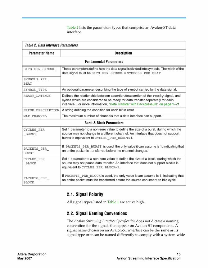
Table 2 lists the parameters types that comprise an Avalon-ST data interface.
2.1. Signal Polarity
All signal types listed in Table 1 are active high.
2.2. Signal Naming Conventions
The Avalon Streaming Interface Specification does not dictate a naming convention for the signals that appear on Avalon-ST components. A signal name chosen on an Avalon-ST interface can be the same as its signal type or it can be named differently to comply with a system-wide
Table 2. Data Interface Parameters
Parameter Name Description
Fundamental Parameters
BITS_PER_SYMBOL These parameters define how the data signal is divided into symbols. The width of the data signal must be BITS_PER_SYMBOL × SYMBOLS_PER_BEAT.
SYMBOLS_PER_BEAT
SYMBOL_TYPE An optional parameter describing the type of symbol carried by the data signal.
READY_LATENCY Defines the relationship between assertion/deassertion of the ready signal, and cycles which are considered to be ready for data transfer separately for each interface. For more information, “Data Transfer with Backpressure” on page 1–21.
ERROR_DESCRIPTION A string defining the condition for each bit in error
MAX_CHANNEL The maximum number of channels that a data interface can support.
Burst & Block Parameters
CYCLES_PER_BURST
Set 1 parameter to a non-zero value to define the size of a burst, during which the source may not change to a different channel. An interface that does not support bursts is equivalent to CYCLES_PER_BURST=1.
If PACKETS_PER_BURST is used, the only value it can assume is 1, indicating that an entire packet is transferred before the channel changes.
PACKETS_PER_BURST
CYCLES_PER_BLOCK
Set 1 parameter to a non-zero value to define the size of a block, during which the source may not pause data transfer. An interface that does not support blocks is equivalent to CYCLES_PER_BLOCK=1.
If PACKETS_PER_BLOCK is used, the only value it can assume is 1, indicating that an entire packet must be transferred before the source can insert an idle cycle.
PACKETS_PER_BLOCK
ltera Corporation 15ay 2007 Avalon Streaming Interface Specification

Data Interface Signals
naming convention. For example, an Avalon-ST component may have a sink interface with an input signal named my_enable_signal, of type valid.
2.3. Signal Sequencing & Timing
This section describes issues related to timing and sequencing of Avalon-ST signals.
2.3.1. Synchronous Interface
All transfers of an Avalon-ST connection occur synchronous to the rising edge of the associated clock signal. All outputs from a source interface to a sink interface, including the data, channel, and error signals, must be registered on the rising edge of clock. The Specification does not require inputs to a sink interface to be registered. Registering signals at the source provides for high frequency operation while eliminating back-to-back registers with no intervening logic. Registers are not required for signals in the sink to source direction.
Avalon-ST interfaces must not be edge sensitive to signals other than the clock, because the signals may transition multiple times before they stabilize. The exact timing of signals toggling and stabilizing between clock edges varies depending upon the characteristics of the Altera device selected to implement the system.
2.3.2. Clock Enables
Avalon-ST components typically do not include a clock enable input, because the Avalon-ST signaling itself is sufficient to determine the cycles that a component should and should not be enabled. Avalon-ST compliant components may have a clock enable input for their internal logic, but they must take care to ensure that the timing of the interface control signals still adheres to the specification.
2.3.3. Performance
There is no fixed or maximum performance of an Avalon-ST interface. The maximum performance is dependent upon component design and system implementation. After synthesis and place-and-route of the system for a specific device, standard timing analysis determines the maximum speed at which transfers can be performed.
16 Altera CorporationAvalon Streaming Interface Specification May 2007

AM
2.3.4. Electrical Characteristics
The Avalon Streaming Interface Specification defines the interface between IP blocks on a programmable logic device. It does not specify any electrical or physical characteristics required by traditional inter-chip interfaces.
2.4. Resets
Each Avalon-ST Streaming interface has an associated active-low reset signal. This reset can be for the interface alone, for the entire component, or for a number of interfaces on the component. The reset used by each interface may be asserted at any time, but must only be deasserted synchronously to the clock used by the interface: Avalon-ST components are not required to do any metastable hardening for reset signals. Avalon-ST components can reset synchronously to the clock signal when the reset signal is asserted, or can be reset synchronously to the falling edge of the reset signal itself. The Avalon-ST specification provides requirements for some control signals while the interface is in reset. The reset requirement for each signal is discussed with the details of the signal. The reset requirements are intentionally kept to a minimum to allow for flexibility in component design.
2.5. Transfer Properties
Different Avalon-ST interfaces have different transfer capabilities, because not all Avalon-ST source and sink interfaces transfer data in the same way. The Avalon Streaming Interface Specification defines a set of properties that transfers can exhibit. An Avalon-ST source or sink interface can support one or more of these properties, depending on the component design. The transfer properties supported by an Avalon-ST component are determined at design time and do not change from transfer to transfer.
The Avalon Streaming Interface Specification defines the following optional transfer properties that source and sink interfaces can implement:
■ Multi-Channel Support■ Packet Support■ Burst and Block Support ■ Component-Specific Signals
The fundamental Avalon-ST transfer does not implement any of these optional transfer properties. It provides a reference point for describing how each transfer property modifies the interface and the behavior of the
ltera Corporation 17ay 2007 Avalon Streaming Interface Specification

Fundamental Data Transfers
Avalon-ST signals. Specific properties may change the behavior of certain signal types or require the use of one or more new signal types or properties.
Avalon-ST interfaces can support multiple properties simultaneously. If the source and sink in a connection support different transfer properties or parameters, it might be necessary for the system designer to insert logic between the interfaces for them to interoperate.
3. Fundamental Data Transfers
This section defines the transfer of data from a source interface to a sink interface. In all cases, the data source and the data sink must comply with the specification. It is not the responsibility of the data sink to detect source protocol errors.
3.1. Signal Details
This section describes the basic Avalon-ST protocol that all data transfers must follow. It also highlights the flexibility a designer has in choosing Avalon-ST signals to meet the needs of a particular component and makes recommendations concerning the signals that should be used.
Figure 2. Fundamental Avalon-ST Interface Signals
■ ready – On interfaces supporting backpressure, ready is asserted by the sink to mark ready cycles, cycles where transfers may take place. Data interfaces that support backpressure must define the READY_LATENCY parameter so that if ready is asserted on cycle N, cycle (N+READY_LATENCY) is considered a ready cycle.
Data Source Data Sink
valid
dataerror
ready
channel<max_channel>
18 Altera CorporationAvalon Streaming Interface Specification May 2007

AM
■ valid – The valid signal qualifies valid data on any cycle where data is being transferred from the source to the sink. Such active cycles are called beats. The valid signal is required by all interfaces. On each active cycle the data signal and other source to sink signals are sampled by the sink.
■ data – The data signal typically carries the bulk of the information being transferred from the source to the sink, and consists of one or more symbols being transferred on every clock cycle. The BITS_PER_SYMBOL parameter defines how the data signal is divided into symbols.
■ symbol_type – The SYMBOL_TYPE parameter is optional. When defined, it specifies the type of data being carried by the interface. This parameter provides system designers with a warning when interfaces that carry different types of data are connected. Many interfaces, including most packet interfaces, do not carry a specific signal type, and should leave SYMBOL_TYPE undefined. Although SYMBOL_TYPE can be any text string, the values in Appendix I should be used when appropriate.
■ error – Errors are signaled with the error signal, where each bit in error corresponds to a possible error condition. A value of zero on any beat indicates the data on that beat is error-free. The action that a component takes when an error is detected is up to the component and is not covered by this specification.
Each source and sink interface specifies the error condition associated with each bit in its error signal using the error_description parameter. The error_description string consists of comma separated list of error descriptions, each of the form [bit]=name:"description". Although the error name can be any text string, standard values should be used so that cores recognize when they share an error. For example, an interface that indicates two error types might use the string shown below. &&&LLB: I need a better example here.
[0]=error_a:"The first Error", [1]=error_b:"The other Error"
Unknown error is a special case used as a for unrecognized errors. If a source interface has errors that the sink does not recognize, these errors are orred together and connected to the sink's unknown error bit.
ltera Corporation 19ay 2007 Avalon Streaming Interface Specification

Fundamental Data Transfers
■ channel – The optional channel signal is driven by the source on every beat to indicate the channel to which the data belongs. The meaning of channel for a given interface depends on the application: some applications use channel as a port number indication, while other applications use channel as a page number or timeslot indication. When the channel signal is used, all of the data transferred in each active cycle belongs to the same channel. The source may change to a different channel on successive active cycles.
An interface that uses the channel signal must define the MAX_CHANNEL parameter to indicate the maximum channel number. If the number of channels that the interface supports varies while the component is operating, MAX_CHANNEL is the maximum channel number that the interface can support.
3.2. Data Layout
Symbol ordering is big endian, such that the first symbol is composed of the most significant bits. Figure 4 shows a data signal with SYMBOLS_PER_BEAT=4 and BITS_PER_SYMBOL=16.
Figure 3. Data Symbols
The timing diagram in Figure 4, provides an example where SYMBOLS_PER_BEAT=4 and BITS_PER_SYMBOL=8.
symbol 0 symbol 3symbol 2symbol 163 48 47 32 31 16 15 0
20 Altera CorporationAvalon Streaming Interface Specification May 2007

AM
Figure 4. Big Endian Layout of Data
4. Data Transfer without Backpressure
The data transfer without backpressure is the most basic of Avalon-ST data transfers. On any given clock cycle, the source interface drives the data and the optional channel and error signals, and asserts valid. The sink interface samples these signals on the rising edge of the reference clock if valid is asserted. Figure 5 shows an example of data transfer without backpressure.
Figure 5. Data Transfer without Backpressure
5. Data Transfer with Backpressure
The sink indicates to the source that it is ready for an active cycle by asserting the ready signal for a single clock cycle. Cycles during which the sink is ready for data are called ready cycles. During a ready cycle, the source may assert valid and provide data to the sink. If it has no data to send, it deasserts valid and can drive data to any value.
clk
ready
valid
channel
error
data[31:24]
data[23:16]
data[15:8]
data[7:0]
D0 D4 D8
D1
D2
D3
D5
D6
D7
D9
DA
DD
DC
DE
DF
D11
D12
DB
D10
D13
clk
valid
channel
error
data D1 D2 D3D0
ltera Corporation 21ay 2007 Avalon Streaming Interface Specification

Data Transfer with Backpressure
Each interface that supports backpressure defines the READY_LATENCY parameter to indicate the number of cycles from the time that ready is asserted until valid data can be driven. If an interface defines READY_LATENCY to be zero, then the cycle during which ready is asserted is the ready cycle. If READY_LATENCY has a positive value for an interface, the interface considers cycle (N + READY_LATENCY) to be a ready cycle if ready is asserted on cycle N. Any interface that includes the ready signal and defines the READY_LATENCY parameter supports backpressure.
When READY_LATENCY=0, data is transferred only when ready and valid are asserted on the same cycle. In this mode of operation, the source does not receive the sink’s ready signal before it begins sending valid data. The source provides the data and asserts valid whenever it can and waits for the sink to capture the data and assert ready. The sink only captures input data from the source when ready and valid are both asserted.
Figure 6 illustrates a transfer with backpressure and READY_LATENCY=0. The source provides data and asserts valid on cycle one, even though the sink isn't ready. The source waits until cycle two, when the sink does assert ready, before moving onto the next data cycle. In cycle three, the source drives data on the same cycle and the sink is ready to receive it; the transfer happens immediately. In cycle four, the sink asserts ready, but the source does not drive valid data.
Figure 6. Transfer with Backpressure, Ready_Latency=0
Figure 7 and Figure 8 show data transfers with READY_LATENCY=1 and READY_LATENCY=2, respectively. In both these cases, ready is asserted before the ready cycle, and the source responds one or two cycles later by providing data and asserting valid. When READY_LATENCY is not zero, the source must deassert valid on non-ready cycles. The sink captures data on any cycle where valid is asserted, regardless of the value of ready on that cycle.
clk
ready
valid
channel
error
data Do D1 D2
0 1 2 3 5 6 7 84
D3
22 Altera CorporationAvalon Streaming Interface Specification May 2007

AM
Figure 7. Transfer with Backpressure, Ready_Latency=1
Figure 8. Transfer with Backpressure, Ready_Latency=2
6. Packet Data Transfers
The packet transfer property adds support for transferring packets from a source interface to a sink interface. Three additional signals are defined to implement the packet transfer.
clk
ready
valid
channel
error
data D1 D2 D3D0
clk
ready
valid
channel
error
data D1 D2 D3D0
ltera Corporation 23ay 2007 Avalon Streaming Interface Specification

Packet Data Transfers
Figure 9. Avalon-ST Packet Interface Signals
6.1. Signal Details
■ startofpacket – The startofpacket signal is required by all interfaces supporting packet transfers and marks the active cycle containing the start of the packet.
■ endofpacket – The endofpacket signal is required by all interfaces supporting packet transfer and marks the active cycle containing the end of the packet.
■ empty – The optional empty signal indicates the number of symbols that are empty during the cycles that mark the end of a packet. The sink only checks the value of the empty signal during active cycles that have endofpacket asserted. The empty symbols are always the last symbols in data, those carried by the low-order bits. The empty signal is required on all packet interfaces whose data signal carries more than one symbol of data and have a variable length packet format. It is not required on those with a fixed length packet format. The size of the empty signal is SYMBOLS_PER_BEAT.
6.2. Protocol Details
Packet data transfer follows the same protocol as the fundamental data transfer described on page 21, with the addition of the startofpacket, endofpacket, and empty.
Data Source Data Sink
valid
data
error
ready
channel
startofpacket
endofpacket
empty
24 Altera CorporationAvalon Streaming Interface Specification May 2007

AM
Figure 10 illustrates the transfer of a 17-byte packet from a source interface to a sink interface, where READY_LATENCY=0 and SYMBOLS_PER_BEAT=4. Data transfer occurs on cycles one, two, four, five, and six, when both ready and valid are asserted. During cycle one, startofpacket is asserted, and the first four bytes of packet are transferred. During cycle six, endofpacket is asserted, and empty has a value of three, indicating that this is the end of the packet and that three of the four symbols are empty.
Figure 10. Packet Transfer
6.2.1. Packet Format
A packet may be subdivided into fields using the PACKET_FORMAT parameter. The PACKET_FORMAT parameter is a string that describes the format of a packet using a number of named fields. If either the source or sink defines a PACKET_FORMAT, all packets must adhere to the specified format.
The PACKET_FORMAT parameter consists of a comma-separated list of field names, indicating the order of the fields in the packet. For example, the A,B,C field string indicates that each packet is three symbols in length, and consists of one symbol of A, one symbol of B, and one symbol of C. The Avalon-ST protocol attaches no meaning to the name of the fields; they are simply text strings to differentiate between fields.
The following rules define the packet_format string:
clk
ready
valid
startofpacket
endofpacket
empty
channel
error
data[31:24]
data[23:16]
data[15:8]
data[7:0]
0 0 0 0 0
0 0 0 0 0
D0 D4 D8 D12 D16
D1 D5 D9 D13
D2 D6 D10 D14
D3 D7 D11 D15
3
1 2 3 4 5 6 7
ltera Corporation 25ay 2007 Avalon Streaming Interface Specification

Packet Data Transfers
■ A packet format string is a comma-separated list of fields, where the number of fields defines the length of each packet. Whitespace is ignored.
■ A field name consists of upper and lowercase letters, numbers, and the underscore, in any order (A-Za-z0-9_).
■ The – (hyphen) field name is reserved to mean unused. The sink ignores any data in this channel, and the source is free to set it to any value.
■ A number in braces following a field indicates that field is repeated. For example, A{3},B{3},C{3} is the same as A,A,A,B,B,B,C,C,C.
■ A plus (+) following a field indicates that the field is repeated one or more times. An asterisk (*) indicates that it is repeated zero or more times. For example, Address{4},Data+,CRC{4} describes a packet with a four address symbols, an undefined number of data symbols, and four CRC symbols.
■ Parentheses can be used to group fields. For example, (A,B,C){3} is equivalent to A,B,C,A,B,C, A,B,C and (A,B,C)+ describes a packet with the A,B,C fields repeated one or more times. Parentheses can be nested.
When the packet format does not contain the + or * characters, the length of each packet is completely defined at compile time. If the length of the packet is defined at compile time and is a multiple of SYMBOLS_PER_ACTIVE_CYCLE, the empty signal is not required.
Figure 11 illustrates the transfer of two (R,G,B){3} packets, where SYMBOLS_PER_ACTIVE_CYCLE is 3. Because the length of each packet is defined to be nine symbols, which is a multiple of SYMBOLS_PER_ACTIVE_CYCLE, the packet is guaranteed to end on a active cycle boundary. The empty signal is not required.
Figure 11. (R,G,B){3} Packet Example
clk
ready
valid
startofpacket
endofpacket
error
data[23:16]
data[15:8]
data[7:0]
0 0 0
R00 R01 R02
G00 G01 G02
B00 B01 B02
0
R10
G10
B10
0 0
R11
G11
B11
R12
G12
B12
26 Altera CorporationAvalon Streaming Interface Specification May 2007

AM
Figure 12 illustrates the transfer of two A{4},D+,C{4} packets, where SYMBOLS_PER_ACTIVE_CYCLE is 4. The first packet contains 7 D symbols, and the second contains 10 D symbols.
Figure 12. A{4}, D+, C{4} packet example
6.2.2. Errors
An error can affect either the current cycle or the entire packet. Errors that affect the entire packet can be asserted anywhere during the packet transfer. The sink interface must interpret per-packet errors, catching error conditions asserted during a packet transfer and taking the appropriate action.
7. Block & Burst Transfers
Bursts and blocks allow interfaces to treat multiple active cycles as a unit, maximizing the throughput for interfaces that achieve the greatest efficiency when handling multiple units of data at a time.
7.1. Signal Details
No additional signals are used for block or burst transfers.
7.2. Blocks & Bursts
The following sections describe burst and block transfers.
clk
ready
valid
startofpacket
endofpacket
empty
error
data[31:24]
data[23:16]
data[16:8]
data[7:0]
A00 D00 A10
21
D04 C01 D10 D14 D18 C12
C02
A01
A02
A03
D01
D02
D03
D05
D06
C00
A11
A12
A13
D11
D12
D13
D15
D16
D17
D19
C10
C11
C13
0 0 0 0 0 0 0 0
C03
ltera Corporation 27ay 2007 Avalon Streaming Interface Specification

Block & Burst Transfers
7.2.1. Bursts
A burst is a transfer to a single channel. If a source interface supports bursts, it guarantees that once it begins a burst transfer to a channel, it will not switch to another channel until the burst is complete.
The source ends a burst when one of two conditions occurs:
■ The amount of data defined by CYCLES_PER_BURST have been transferred.
■ The endofpacket signal is asserted.
For packet interfaces, the burst is always ended if endofpacket is asserted. Once a burst is complete, the source may immediately send another burst for the same channel or a different channel.
The size of a burst is defined by a non-zero value for either one of the following parameters:
■ CYCLES_PER_BURST■ PACKETS_PER_BURST
If PACKETS_PER_BURST is used, it must be set to one, indicating that an entire packet must be transferred before the channel changes. An interface that does not support bursts is equivalent to CYCLES_PER_BURST=1. The source may deassert valid and insert idle cycles at any time during a burst, and the sink is free to deassert ready at any time during a burst. A burst for a channel may be immediately followed by another burst for the same channel.
Figure 13 illustrates a packet transfer using bursts, where CYCLES_PER_BURST=2. Bursts one, two, and three are simple bursts that are terminated because the burst size requirement has been met. Burst four is terminated by the assertion of the endofpacket signal, and is immediately followed by another burst for the same channel.
28 Altera CorporationAvalon Streaming Interface Specification May 2007

AM
Figure 13. Burst Transfers, Cycles_Per_Burst=2
7.2.2. Blocks
In contrast to bursts, blocks are a guarantee to transfer a block of data without inserting idle cycles or changing channels. The sink that defines a block size requires uninterrupted data for the same channel for the duration of the block. Blocks are similar to bursts, but more restrictive because the source also guarantees that it will not insert idle cycles. The block size is defined by a non-zero value the CYCLES_PER_BLOCK or PACKETS_PER_BLOCK parameters. PACKETS_PER_BLOCK, if used, must be set to one, indicating that a block consists of an entire packet. An interface that does not support blocks is equivalent to CYCLES_PER_BLOCK=1.
7.2.3. Using Bursts and Blocks Together
If bursts and blocks are defined on the same interface, then either PACKETS_PER_BLOCK and PACKETS_PER_BURST are both set to one, or the size of a burst is an integer multiple of the size of a block. An interface that defines blocks but not bursts is equivalent to an interface that defines bursts to be the same size as blocks. Figure 14 illustrates an
clk
ready
valid
error
channel
startofpacket
endofpacket
empty
data[31:24]
data[23:16]
data[15:8]
data[7:0]
Burst2Burst1 Burst3 B4 Bst5 Burst6 Burst7
0 0 0 0 0 0 0 0 0
0 0 1 2 0 0 0 2 2 1
2 3
000
001
002
004
005
006
007
100
101
102
103
104 200
201
202
203
204
205
206
207
008
009
00A
00B
00C
00D
00E 208
209
20A
20B
20C
20D
20E
20F
108
109
0
1
0 0
2
0
1
003
105
106
107
00F
010
011
10A
10B
ltera Corporation 29ay 2007 Avalon Streaming Interface Specification

Component-Specific Signals
interface where the CYCLES_PER_BLOCK=2 and the CYCLES_PER_BURST=4. In Figure 13, burst three has only one active cycle and is terminated by the endofpacket signal.
Figure 14. Block & Burst Transfers, cycles_per_block=2, cycles_per_burst=4
8. Component-Specific Signals
The Avalon-ST interface is extensible, allowing designers to specify the additional component-specific signals necessary for a particular streaming application. Component-specific signals potentially limit the component's interoperability with other components, reducing the number of applications in which it can be used.
An Avalon-ST data interface can include component-specific signals that follow the same timing and flow control rules as the data signal and are connected from a source interface to a sink interface when a source-sink connection is created.
A component-specific signal is any signal whose type is not defined by previous sections of this specification. Four parameters are defined to characterize component-specific signals.
■ TYPE
clk
ready
valid
startofpacket
endofpacket
error
channel
empty
data[31:24]
data[23:16]
data[15:8]
data[7:0]
Blk1 Blk2 Blk3 Blk4 Blk5 Blk6 B7
Burst1 Burst2 Brst3 Burst4
0 0 0 0 00 0 00 0 0 0
0 0 0 0 1 1 1 1 0 0 0 0
3 2
000
001
002
003
004
005
006
007 008
009
00A
00B 00C
00E
00F
100
101
102
103
104
105
106
107
108
109
10A
10B
10C
10D
10E
10F
110 010
011
012
013
014
015
016
017
018
01900D
30 Altera CorporationAvalon Streaming Interface Specification May 2007

AM
■ IS_REQUIRED■ DEFAULT_VALUE■ TREAT_AS
In contrast to other parameters which are defined for the entire source or sink interface, these parameters are defined for individual signals.
8.1. Is_Required
Each component-specific signal must define the IS_REQUIRED parameter, where IS_REQUIRED=1 indicates that the interface cannot be connected to an adjacent interface unless the interface has a matching signal. If IS_REQUIRED=0, a connection can occur even if the adjacent interface does not have a matching signal. For a source interface, if a component-specific signal has IS_REQUIRED=0 and does not have a matching signal on the sink interface, the component specific signal is left unconnected. For a sink interface, if a component specific signal has IS_REQUIRED=0, then the DEFAULT_VALUE parameter must also be defined. If the adjacent interface does not have a matching signal, the component-specific signal is assigned the default value.
For example, a component that performs error correction on input data may have a component-specific signal with IS_REQUIRED=0 used to indicate which errors were corrected. If the adjacent component is interested in which errors were corrected and has a matching input, then the signal is connected. However, if the adjacent component is interested only in the corrected data and does not have a matching input signal, the additional output signal is left unconnected.
Table 3. Data Interface Parameters
Parameter Name Description
Component Specific Signal Parameters
TYPE For each component-specific signal, this defines the type of the signal. This cannot be one of the types described in Table 1.
IS_REQUIRED For each component-specific signal, this parameter indicates if the interface can be connected to an adjacent interface that does not have a matching signal of the same type.
DEFAULT_VALUE For each component-specific input signal that has IS_REQUIRED=0, this parameter indicates the default value to be used for the input signal if the adjacent interface has no matching component-specific signal.
TREAT_AS Specifies how the signal is to be treated by adaptation logic and common components.
ltera Corporation 31ay 2007 Avalon Streaming Interface Specification

Component-Specific Signals
8.2. Treat_As
For component-specific signals, the optional TREAT_AS parameter may be defined to specify how the signal should be treated by adaptation logic. This parameter is typically used when a data format adapter changes the width of the data signal. If TREAT_AS=data, the adaptation logic treats the signal like data. If TREAT_AS=startofpacket, the adaptation logic treats the signal in the same manner as the startofpacket signal, maintaining its alignment with the start of the packet.
1 For the special case when a signal with TREAT_AS equal to startofpacket or endofpacket signal is routed through a bus width converter causing one input cycle to become N output active cycles (with 1/N symbols per active cycle), the bus width adapter will force the value of the startofpacket or endofpacket signal to zero for the additional cycles as appropriate.
32 Altera CorporationAvalon Streaming Interface Specification May 2007

AM
9. Appendix I. Common Symbol Types
Table 4 lists symbol types that components use as of the release of this specification. When defining a new symbol type, the component designer should consult this table to ensure that a suitable symbol type does not already exist. Many interfaces, such as packet interfaces, do not carry a specific signal type. These interfaces should leave signal_type undefined.
Table 4. Common Symbol Types
Symbol_type parameter Description
unsigned
Each symbol consists of a single non-complex signed, unsigned, signed binary fractional, unsigned binary fractional, or floating-point data number.
signed
signed_binary_fractional
unsigned_binary_fractional
floating_point
ltera Corporation 33ay 2007 Avalon Streaming Interface Specification

Appendix II. Common Error Conditions
10.Appendix II. Common Error Conditions
Table 5 lists error conditions that components specify as of the release of this specification. When defining a new error condition, the component designer should consult this table to ensure that a suitable error condition does not already exist.
Table 5. Common Error Conditions
error_description value Description
crc Data is marked as an error due to a CRC or checksum error.
parity Data is marked as an error due to a parity error.
overflow Data is marked as an error due to a buffer overflow.
sync Data is marked as an error because the receiver was out of sync.
unexpected_endofpacket For interfaces that have a completely defined packet format, this error marks packets where endofpacket was asserted before a complete packet's worth of data was received.
missing_endofpacket For interfaces using the optional endofpacket signal, this error marks packets where startofpacket was asserted for a channel before the end of the previous packet.
missing_startofpacket For interfaces using the optional startofpacket signal, this error marks packets where an endofpacket was asserted for a channel before startofpacket.
channel_outofrange This error indicates that the value of the channel signal was out of range.
34 Altera CorporationAvalon Streaming Interface Specification May 2007

AM
11.Document Revision History
Table 6 shows the revision history for this document.
Table 6. Document Revision History
Date & Document Version Changes Made Summary of Changes
May 2007v1.1
Completed definition for empty signal in Table 1. Added revision history, contact information and typographical conventions sections.
Document now includes standard front matter.
November 2006v1.0
Initial release —
ltera Corporation 35ay 2007 Avalon Streaming Interface Specification

Document Revision History
36 Altera CorporationAvalon Streaming Interface Specification May 2007