avaya switch manual
TRANSCRIPT
Configuration — IP Routing ProtocolsAvaya Ethernet Routing Switch 5000Series
6.2NN47200-503, 06.02
December 2010
© 2010 Avaya Inc.
All Rights Reserved.
Notice
While reasonable efforts have been made to ensure that theinformation in this document is complete and accurate at the time ofprinting, Avaya assumes no liability for any errors. Avaya reserves theright to make changes and corrections to the information in thisdocument without the obligation to notify any person or organization ofsuch changes.
Documentation disclaimer
Avaya shall not be responsible for any modifications, additions, ordeletions to the original published version of this documentation unlesssuch modifications, additions, or deletions were performed by Avaya.End User agree to indemnify and hold harmless Avaya, Avaya's agents,servants and employees against all claims, lawsuits, demands andjudgments arising out of, or in connection with, subsequentmodifications, additions or deletions to this documentation, to theextent made by End User.
Link disclaimer
Avaya is not responsible for the contents or reliability of any linked Websites referenced within this site or documentation(s) provided by Avaya.Avaya is not responsible for the accuracy of any information, statementor content provided on these sites and does not necessarily endorsethe products, services, or information described or offered within them.Avaya does not guarantee that these links will work all the time and hasno control over the availability of the linked pages.
Warranty
Avaya provides a limited warranty on this product. Refer to your salesagreement to establish the terms of the limited warranty. In addition,Avaya’s standard warranty language, as well as information regardingsupport for this product, while under warranty, is available to Avayacustomers and other parties through the Avaya Support Web site: http://www.avaya.com/support. Please note that if you acquired theproduct from an authorized Avaya reseller outside of the United Statesand Canada, the warranty is provided to you by said Avaya reseller andnot by Avaya.
Licenses
THE SOFTWARE LICENSE TERMS AVAILABLE ON THE AVAYAWEBSITE, HTTP://SUPPORT.AVAYA.COM/LICENSEINFO/ AREAPPLICABLE TO ANYONE WHO DOWNLOADS, USES AND/ORINSTALLS AVAYA SOFTWARE, PURCHASED FROM AVAYA INC.,ANY AVAYA AFFILIATE, OR AN AUTHORIZED AVAYA RESELLER(AS APPLICABLE) UNDER A COMMERCIAL AGREEMENT WITHAVAYA OR AN AUTHORIZED AVAYA RESELLER. UNLESSOTHERWISE AGREED TO BY AVAYA IN WRITING, AVAYA DOESNOT EXTEND THIS LICENSE IF THE SOFTWARE WAS OBTAINEDFROM ANYONE OTHER THAN AVAYA, AN AVAYA AFFILIATE OR ANAVAYA AUTHORIZED RESELLER, AND AVAYA RESERVES THERIGHT TO TAKE LEGAL ACTION AGAINST YOU AND ANYONEELSE USING OR SELLING THE SOFTWARE WITHOUT A LICENSE.BY INSTALLING, DOWNLOADING OR USING THE SOFTWARE, ORAUTHORIZING OTHERS TO DO SO, YOU, ON BEHALF OFYOURSELF AND THE ENTITY FOR WHOM YOU ARE INSTALLING,DOWNLOADING OR USING THE SOFTWARE (HEREINAFTERREFERRED TO INTERCHANGEABLY AS “YOU” AND “END USER”),AGREE TO THESE TERMS AND CONDITIONS AND CREATE ABINDING CONTRACT BETWEEN YOU AND AVAYA INC. OR THEAPPLICABLE AVAYA AFFILIATE (“AVAYA”).
Copyright
Except where expressly stated otherwise, no use should be made ofmaterials on this site, the Documentation(s) and Product(s) providedby Avaya. All content on this site, the documentation(s) and theproduct(s) provided by Avaya including the selection, arrangement anddesign of the content is owned either by Avaya or its licensors and is
protected by copyright and other intellectual property laws including thesui generis rights relating to the protection of databases. You may notmodify, copy, reproduce, republish, upload, post, transmit or distributein any way any content, in whole or in part, including any code andsoftware. Unauthorized reproduction, transmission, dissemination,storage, and or use without the express written consent of Avaya canbe a criminal, as well as a civil, offense under the applicable law.
Third-party components
Certain software programs or portions thereof included in the Productmay contain software distributed under third party agreements (“ThirdParty Components”), which may contain terms that expand or limitrights to use certain portions of the Product (“Third Party Terms”).Information regarding distributed Linux OS source code (for thoseProducts that have distributed the Linux OS source code), andidentifying the copyright holders of the Third Party Components and theThird Party Terms that apply to them is available on the Avaya SupportWeb site: http://www.avaya.com/support/Copyright/.
Trademarks
The trademarks, logos and service marks (“Marks”) displayed in thissite, the documentation(s) and product(s) provided by Avaya are theregistered or unregistered Marks of Avaya, its affiliates, or other thirdparties. Users are not permitted to use such Marks without prior writtenconsent from Avaya or such third party which may own the Mark.Nothing contained in this site, the documentation(s) and product(s)should be construed as granting, by implication, estoppel, or otherwise,any license or right in and to the Marks without the express writtenpermission of Avaya or the applicable third party.
Avaya is a registered trademark of Avaya Inc.
All other trademarks are the property of their respective owners.
Downloading documents
For the most current versions of documentation, see the Avaya SupportWeb site: http://www.avaya.com/support
Contact Avaya Support
Avaya provides a telephone number for you to use to report problemsor to ask questions about your product. The support telephone numberis 1-800-242-2121 in the United States. For additional supporttelephone numbers, see the Avaya Web site: http://www.avaya.com/support
2 Configuration — IP Routing Protocols December 2010
Contents
Chapter 1: New in this release...............................................................................................13Features..........................................................................................................................................................13Other changes.................................................................................................................................................17
Chapter 2: Introduction...........................................................................................................19ACLI command modes....................................................................................................................................19
Chapter 3: IP Routing Fundamentals....................................................................................21IP addressing overview...................................................................................................................................21
Subnet addressing..................................................................................................................................23IP routing.........................................................................................................................................................24
IP routing using VLANs..........................................................................................................................25Local routes............................................................................................................................................25Local and non-local static routes............................................................................................................27Default routes.........................................................................................................................................27Management VLAN................................................................................................................................27Multinetting.............................................................................................................................................30Brouter port.............................................................................................................................................31
Routing Information Protocol (RIP).................................................................................................................32RIP operation..........................................................................................................................................32RIP metrics.............................................................................................................................................33Routing updates.....................................................................................................................................34Split horizon............................................................................................................................................34Triggered updates...................................................................................................................................34RIP Send and Receive Modes...............................................................................................................35Supported RIP capabilities on the 5000 switch......................................................................................36RIP limitations.........................................................................................................................................36
Open Shortest Path First (OSPF) protocol......................................................................................................37Overview.................................................................................................................................................37Autonomous system and areas..............................................................................................................38ASBR and external router advertisements.............................................................................................40OSPF neighbors.....................................................................................................................................41Designated routers.................................................................................................................................41OSPF operation......................................................................................................................................42OSPF router advertisements..................................................................................................................42Router types...........................................................................................................................................43LSA types...............................................................................................................................................43Area types..............................................................................................................................................45OSPF virtual link.....................................................................................................................................48OSPF host route.....................................................................................................................................50OSPF interfaces.....................................................................................................................................50OSPF packets........................................................................................................................................51OSPF metrics.........................................................................................................................................52Automatic router ID change in a stack....................................................................................................52OSPF security mechanisms...................................................................................................................53
Equal Cost MultiPath (ECMP).........................................................................................................................54Route policies..................................................................................................................................................54
Route policies in a stack.........................................................................................................................56
Configuration — IP Routing Protocols December 2010 3
DHCP relay.....................................................................................................................................................56Forwarding DHCP packets.....................................................................................................................57Multiple DHCP servers...........................................................................................................................58Differences between DHCP and BootP..................................................................................................59
IP forwarding next-hop....................................................................................................................................60Limitations..............................................................................................................................................61
UDP broadcast forwarding..............................................................................................................................61Directed broadcasts........................................................................................................................................62ARP.................................................................................................................................................................62Static ARP.......................................................................................................................................................63Proxy ARP.......................................................................................................................................................63IP blocking for stacks......................................................................................................................................64Virtual Router Redundancy Protocol (VRRP)..................................................................................................65
VRRP operation......................................................................................................................................66VRRP topology example........................................................................................................................67Critical IP address..................................................................................................................................69VRRP and SMLT....................................................................................................................................69VRRP fast advertisement interval...........................................................................................................70
Chapter 4: IP multicast fundamentals...................................................................................73Overview of IP multicast..................................................................................................................................73
Multicast groups.....................................................................................................................................76Multicast distribution trees......................................................................................................................76Multicast addresses................................................................................................................................78IP multicast address ranges...................................................................................................................78IP to Ethernet multicast MAC mapping...................................................................................................79
Internet Group Management Protocol.............................................................................................................80IGMPv1 operation...................................................................................................................................81IGMPv2 operation...................................................................................................................................82IGMPv3 operation...................................................................................................................................85IGMPv3 Membership Report..................................................................................................................86IGMPv3 Membership Query...................................................................................................................87Multicast flow over Multi-Link Trunking...................................................................................................88IGMP requests for comment...................................................................................................................88
IGMP snooping...............................................................................................................................................88IGMPv3 snooping...................................................................................................................................90IGMP proxy.............................................................................................................................................91Report forwarding...................................................................................................................................92Static mrouter port and nonquerier.........................................................................................................93Unknown multicast packet filtering.........................................................................................................93IGMP snooping configuration rules........................................................................................................95IGMP and stacking.................................................................................................................................96Default IGMP values...............................................................................................................................96IGMP snooping interworking with Windows clients................................................................................97
IGMP Send Query...........................................................................................................................................98Protocol Independent Multicast-Sparse Mode................................................................................................98
PIM-SM concepts and terminology.........................................................................................................99PIM-SM shared trees and shortest-path trees......................................................................................103Source-to-RP SPT................................................................................................................................107Register suppression timeout...............................................................................................................107Receivers leaving a group....................................................................................................................108
4 Configuration — IP Routing Protocols December 2010
PIM assert............................................................................................................................................108PIM passive interfaces..................................................................................................................................108PIM-SM capabilities and limitations..............................................................................................................109Enabling or disabling routing with IGMP enabled..........................................................................................110Nonsupported IGMP features........................................................................................................................111Default PIM-SM values..................................................................................................................................111
Chapter 5: IPv6 routing fundamentals.................................................................................113IPv6 routing features.....................................................................................................................................113Host autoconfiguration...................................................................................................................................114IPv6 static routes...........................................................................................................................................115Management route........................................................................................................................................117IPv6 DHCP Relay..........................................................................................................................................118
Remote ID.............................................................................................................................................118IPv6-in-IPv4 tunnels......................................................................................................................................119
Tunneling limitations.............................................................................................................................120
Chapter 6: IP routing configuration using ACLI.................................................................121Configuring global IP routing status..............................................................................................................122Displaying global IP routing status................................................................................................................122Configuring an IP address for a VLAN..........................................................................................................123Configuring IP routing status on a VLAN......................................................................................................123Configuring a secondary IP address for a VLAN..........................................................................................124Displaying the IP address configuration and routing status for a VLAN........................................................125Displaying IP routes......................................................................................................................................126Performing a traceroute................................................................................................................................128Entering Router Configuration mode.............................................................................................................129
Chapter 7: Brouter port configuration using ACLI.............................................................131Configuring a brouter port.............................................................................................................................131Displaying the brouter port configuration......................................................................................................132
Chapter 8: Static route configuration using ACLI..............................................................135Configuring a static route..............................................................................................................................135Displaying static routes.................................................................................................................................136Configuring a management route..................................................................................................................137Displaying the management routes...............................................................................................................138
Chapter 9: OSPF configuration using ACLI........................................................................141Configuring the OSPF hardware mode.........................................................................................................142Configuring the router ID...............................................................................................................................143Configuring global OSPF status....................................................................................................................143Configuring global OSPF parameters...........................................................................................................144Displaying global OSPF parameters.............................................................................................................145Configuring OSPF area parameters..............................................................................................................145Displaying OSPF area configuration.............................................................................................................147Displaying OSPF area range information......................................................................................................147Enabling OSPF routing on an interface.........................................................................................................148Assigning an interface to an OSPF area.......................................................................................................149Configuring the OSPF properties for an interface.........................................................................................149Displaying OSPF interface timers.................................................................................................................151Displaying OSPF interface configurations.....................................................................................................151
Configuration — IP Routing Protocols December 2010 5
Displaying OSPF neighbors..........................................................................................................................152Specifying a router as an ASBR....................................................................................................................152Configuring the OSPF authentication type for an interface...........................................................................153Defining simple authentication keys for OSPF interfaces.............................................................................153Defining MD5 keys for OSPF interfaces.......................................................................................................154Displaying OSPF MD5 keys..........................................................................................................................154Applying an MD5 key to an OSPF interface..................................................................................................155Displaying OSPF interface authentication configuration...............................................................................156Configuring a virtual link................................................................................................................................156Creating a virtual interface message digest key...........................................................................................158Configuring automatic virtual links................................................................................................................158Displaying OSPF virtual links........................................................................................................................161Displaying OSPF virtual neighbors...............................................................................................................161Configuring an OSPF host route...................................................................................................................162Displaying OSPF host routes........................................................................................................................163Displaying the OSPF link state database......................................................................................................163Displaying the external link state database...................................................................................................164Initiating an SPF run to update the OSPF LSDB..........................................................................................164Displaying OSPF default port metrics...........................................................................................................165Displaying OSPF statistics............................................................................................................................165Displaying OSPF interface statistics.............................................................................................................165Clearing OSPF statistics counters................................................................................................................166
Chapter 10: OSPF configuration examples using ACLI.....................................................167Basic OSPF configuration examples.............................................................................................................167Advanced OSPF configuration examples.....................................................................................................170
Configuring Autonomous System Border Routers (ASBR)..................................................................176Configuring a multi-area complex.........................................................................................................184
Diagnosing neighbor state problems.............................................................................................................213
Chapter 11: RIP configuration using ACLI..........................................................................217Configuring the global RIP status..................................................................................................................218Configuring the RIP global timeout, holddown timer, and update timer........................................................218Configuring the default RIP metric value.......................................................................................................219Displaying global RIP information.................................................................................................................220Configuring the RIP status on an interface...................................................................................................221Configuring RIP parameters for an interface.................................................................................................221Displaying RIP interface configuration..........................................................................................................223Manually triggering a RIP update..................................................................................................................225
Chapter 12: RIP configuration examples using ACLI........................................................227
Chapter 13: ECMP configuration using ACLI.....................................................................237Configuring the number of ECMP paths allotted for RIP...............................................................................237Configuring the number of ECMP paths allotted for OSPF...........................................................................238Configuring the number of ECMP paths allotted for static routes.................................................................239Displaying ECMP path information...............................................................................................................239ECMP configuration examples......................................................................................................................240
Chapter 14: Route policies configuration using ACLI.......................................................243Configuring prefix lists...................................................................................................................................244Configuring route maps.................................................................................................................................244
6 Configuration — IP Routing Protocols December 2010

Displaying route maps...................................................................................................................................246Applying a RIP accept (in) policy..................................................................................................................247Applying a RIP announce (out) policy...........................................................................................................248Configuring an OSPF accept policy..............................................................................................................249Applying the OSPF accept policy..................................................................................................................250Displaying the OSPF accept policy...............................................................................................................251Configuring an OSPF redistribution policy....................................................................................................251Applying the OSPF redistribution policy........................................................................................................252Displaying the OSPF redistribution policy.....................................................................................................253Configuring IP forwarding next-hop...............................................................................................................253Displaying the IP forwarding next-hop configuration.....................................................................................255
Chapter 15: DHCP relay configuration using ACLI............................................................257Configuring global DHCP relay status...........................................................................................................258Displaying the global DHCP relay status......................................................................................................259Specifying a local DHCP relay agent and remote DHCP server...................................................................259Configuring DHCP relay maximum frame.....................................................................................................260Displaying the DHCP relay configuration......................................................................................................260Configuring DHCP relay status and parameters on a VLAN.........................................................................261Configuring DHCP relay option 82 globally...................................................................................................262Configuring DHCP relay option 82 on a port.................................................................................................262Displaying the DHCP relay configuration for a VLAN...................................................................................263Displaying DHCP relay counters...................................................................................................................264Clearing DHCP relay counters for a VLAN...................................................................................................265
Chapter 16: UDP broadcast forwarding configuration using ACLI..................................267Configuring UDP protocol table entries.........................................................................................................268Displaying the UDP protocol table................................................................................................................268Configuring a UDP forwarding list.................................................................................................................269Applying a UDP forwarding list to a VLAN....................................................................................................270Displaying the UDP broadcast forwarding configuration...............................................................................271Clearing UDP broadcast counters on an interface........................................................................................273
Chapter 17: Directed broadcasts configuration using ACLI.............................................275Directed broadcasts configuration navigation...............................................................................................275Configuring directed broadcasts...................................................................................................................275Displaying the directed broadcast configuration...........................................................................................276
Chapter 18: Static ARP and Proxy ARP configuration using ACLI..................................277Static ARP configuration...............................................................................................................................277
Configuring a static ARP entry.............................................................................................................277Displaying the ARP table..............................................................................................................................278
Displaying ARP entries.........................................................................................................................279Configuring a global timeout for ARP entries.......................................................................................280Clearing the ARP cache.......................................................................................................................280
Proxy ARP configuration...............................................................................................................................281Configuring proxy ARP status..............................................................................................................281Displaying proxy ARP status on a VLAN..............................................................................................282
Chapter 19: IP blocking configuration using ACLI.............................................................283IP blocking configuration navigation..............................................................................................................283Configuring IP blocking for a stack................................................................................................................283
Configuration — IP Routing Protocols December 2010 7
Displaying IP blocking status........................................................................................................................284
Chapter 20: VRRP configuration using ACLI......................................................................285Configuring global VRRP status....................................................................................................................286Assigning an IP address to a virtual router ID...............................................................................................286Configuring the router priority for a virtual router ID......................................................................................287Configuring the status of the virtual router....................................................................................................288Configuring a backup master........................................................................................................................288Configuring the critical IP address................................................................................................................289Configuring the VRRP critical IP status.........................................................................................................289Configuring the VRRP holddown timer.........................................................................................................290Configuring VRRP holddown action..............................................................................................................291Configuring the VRRP advertisement interval...............................................................................................291Configuring the fast advertisement interval...................................................................................................292Configuring fast advertisement status...........................................................................................................292Configuring ICMP echo replies.....................................................................................................................293Enabling VRRP traps....................................................................................................................................294Displaying VRRP configuration and statistics...............................................................................................294
Chapter 21: VRRP configuration examples using ACLI....................................................297Configuring normal VRRP operation.............................................................................................................297Configuring VRRP with SMLT.......................................................................................................................302Configuring VRRP with SLT..........................................................................................................................307
Chapter 22: IGMP snooping configuration using ACLI.....................................................309Configuring IGMP snooping on a VLAN........................................................................................................312Configuring IGMP send query on a VLAN....................................................................................................313Configuring IGMP proxy on a VLAN.............................................................................................................314Configuring the IGMP version on a VLAN.....................................................................................................315Configuring static mrouter ports on a VLAN..................................................................................................316Displaying IGMP snoop, proxy, and mrouter configuration...........................................................................317Configuring IGMP parameters on a VLAN....................................................................................................317Configuring the router alert option on a VLAN..............................................................................................319Displaying IGMP interface information..........................................................................................................320Displaying IGMP group membership information..........................................................................................321Configuring unknown multicast packet filtering.............................................................................................323Displaying the status of unknown multicast packet filtering..........................................................................324Specifying a multicast MAC address to be allowed to flood a VLAN............................................................324Displaying the multicast MAC addresses for which flooding is allowed........................................................325Displaying IGMP cache information..............................................................................................................326Flushing the router table...............................................................................................................................327Configuring IGMP selective channel block....................................................................................................327
Chapter 23: PIM configuration using ACLI.........................................................................329Enabling and disabling PIM-SM globally.......................................................................................................333Configuring global PIM-SM properties..........................................................................................................333Displaying global PIM-SM properties............................................................................................................335Enabling PIM-SM on a VLAN........................................................................................................................336Configuring the PIM-SM interface type on a VLAN.......................................................................................336Displaying PIM-SM neighbors.......................................................................................................................337Configuring PIM-SM properties on a VLAN..................................................................................................338Displaying the PIM-SM configuration for a VLAN.........................................................................................339
8 Configuration — IP Routing Protocols December 2010
Specifying the router as a candidate BSR on a VLAN..................................................................................340Displaying the BSR configuration..................................................................................................................341Specifying a local IP interface as a candidate RP.........................................................................................342Displaying the candidate RP configuration...................................................................................................343Displaying the PIM-SM RP set......................................................................................................................344Displaying the active RP per group...............................................................................................................344Enabling and disabling static RP...................................................................................................................345Configuring a static RP.................................................................................................................................346Displaying the static RP configuration...........................................................................................................347Specifying a virtual neighbor on an interface................................................................................................348Displaying the virtual neighbor configuration................................................................................................348Displaying the PIM mode..............................................................................................................................349Displaying multicast route information..........................................................................................................349
Chapter 24: PIM-SM configuration example using ACLI...................................................353
Chapter 25: Basic IPv6 routing configuration using ACLI................................................363Basic IPv6 routing configuration procedures.................................................................................................363Configuring global IPv6 routing status..........................................................................................................364Displaying global IPv6 configuration.............................................................................................................364Configuring an IPv6 address for a VLAN......................................................................................................365Removing the IPv6 address configuration from a VLAN...............................................................................366Displaying IPv6 address configuration for a VLAN.......................................................................................367Configuring neighbor discovery prefixes.......................................................................................................367Displaying neighbor discovery prefix configuration.......................................................................................369Configuring router advertisement..................................................................................................................369Configuring IPv6 ICMP..................................................................................................................................371Configuring IPv6 static routes.......................................................................................................................372Displaying IPv6 static routes.........................................................................................................................373Adding static entries to the neighbor cache..................................................................................................374Displaying the neighbor cache......................................................................................................................375
Chapter 26: IPv6 DHCP Relay configuration using ACLI...................................................377Specifying a local DHCP relay agent and remote DHCP server...................................................................377Displaying the DHCP relay configuration......................................................................................................379Configuring DHCP relay status and parameters on a VLAN.........................................................................379Displaying the DHCP relay configuration for a VLAN...................................................................................380Displaying DHCP relay counters...................................................................................................................381
Chapter 27: IPv6 Tunnel configuration using ACLI............................................................383IPv6 tunnel configuration procedures............................................................................................................383Configuring manual IPv6-in-IPv4 tunnels using the ACLI.............................................................................383Displaying manual tunnel configuration........................................................................................................385
Chapter 28: IP routing configuration using Enterprise Device Manager.........................387Configuring global IP routing status and ARP lifetime using EDM................................................................388Configuring an IP address and enabling routing for a VLAN using EDM......................................................389Displaying configured IP Addresses using EDM...........................................................................................390
Chapter 29: Static route configuration using Enterprise Device Manager......................393Configuring static routes using EDM.............................................................................................................393Displaying IP Routes using EDM..................................................................................................................395
Configuration — IP Routing Protocols December 2010 9
Filtering route information using EDM..................................................................................................396Displaying TCP information for the switch using EDM..................................................................................397Displaying TCP Connections using EDM......................................................................................................398Displaying TCP Listeners using EDM...........................................................................................................399Displaying UDP endpoints using EDM..........................................................................................................400
Chapter 30: Brouter port configuration using Enterprise Device Manager.....................403Configuring a brouter port using EDM...........................................................................................................403
Chapter 31: OSPF configuration using Enterprise Device Manager................................405Configuring Global OSPF properties using EDM..........................................................................................406
Configuring an automatic virtual link using EDM..................................................................................408Configuring an OSPF area using EDM.........................................................................................................408Configuring an area aggregate range using EDM.........................................................................................410Configuring OSPF stub area metrics using EDM..........................................................................................412Configuring OSPF interfaces using EDM......................................................................................................413Configuring OSPF interface metrics using EDM...........................................................................................415Defining MD5 keys for OSPF interfaces using EDM.....................................................................................416Displaying OSPF neighbor information using EDM......................................................................................417Configuring an OSPF virtual link using EDM................................................................................................418Defining MD5 keys for OSPF virtual links using EDM...................................................................................420Displaying virtual neighbor information using EDM.......................................................................................421Configuring OSPF host routes using EDM....................................................................................................423Displaying link state database information using EDM.................................................................................424Displaying external link state database information using EDM...................................................................425Displaying OSPF statistics using EDM.........................................................................................................426Displaying VLAN OSPF statistics using EDM...............................................................................................428
Chapter 32: RIP configuration using Enterprise Device Manager....................................431Configuring RIP using EDM..........................................................................................................................431Configuring Global RIP properties using EDM..............................................................................................432Configuring a RIP interface using EDM........................................................................................................433Configuring advanced RIP interface properties using EDM..........................................................................434Displaying RIP Statistics using EDM.............................................................................................................436Configuring RIP parameters for a VLAN using EDM....................................................................................437
Chapter 33: ECMP configuration using Enterprise Device Manager................................439Configuring ECMP using EDM......................................................................................................................439
Chapter 34: Route policies configuration using Enterprise Device Manager.................441Creating a prefix list using EDM....................................................................................................................442Creating a route policy using EDM................................................................................................................443Configuring RIP in and out policies using EDM............................................................................................445Configuring an OSPF Accept Policy using EDM...........................................................................................446Configuring OSPF redistribution parameters using EDM..............................................................................447Applying an OSPF accept or redistribution policy using EDM......................................................................449Configuring the global IP forwarding next-hop status...................................................................................450Configuring an IP forwarding next-hop policy...............................................................................................450
Chapter 35: DHCP relay configuration using Enterprise Device Manager......................453Configuring global DHCP Relay status and parameters...............................................................................454Configuring a DHCP Relay forwarding path using EDM...............................................................................454
10 Configuration — IP Routing Protocols December 2010
Configuring DHCP parameters on a VLAN using EDM................................................................................ 456Configuring DHCP Relay option 82 on a VLAN............................................................................................ 457Configuring DHCP Relay option 82 on a port............................................................................................... 457
Chapter 36: UDP broadcast forwarding configuration using Enterprise Device Manager.................................................................................................................................................459
Configuring UDP protocol table entries using EDM...................................................................................... 460Configuring UDP forwarding entries using EDM...........................................................................................461Configuring a UDP forwarding list using EDM.............................................................................................. 462Applying a UDP forwarding list to a VLAN using EDM..................................................................................463
Chapter 37: Static ARP and Proxy ARP configuration using Enterprise Device Manager.................................................................................................................................................465
Configuring static ARP entries using EDM....................................................................................................465Configuring Proxy ARP using EDM...............................................................................................................466
Chapter 38: VRRP configuration using Enterprise Device Manager................................469Configuring global VRRP status and properties using EDM.........................................................................470Assigning an IP address to a virtual router ID using EDM............................................................................ 471Configuring VRRP interface properties using EDM...................................................................................... 472Graphing VRRP interface information using EDM........................................................................................ 474Viewing general VRRP statistics using EDM................................................................................................ 476
Chapter 39: IGMP snooping configuration using Enterprise Device Manager................477Configuring IGMP snoop, proxy, and IGMP parameters on a VLAN using EDM..........................................478Configuring IGMP snoop, proxy, and static mrouter ports on a VLAN using EDM....................................... 480Flushing the IGMP router tables and configuring IGMP router alert using EDM...........................................481Configuring unknown multicast filtering using EDM......................................................................................484Specifying a multicast MAC address to be allowed to flood all VLANs using EDM......................................485Specifying an IP address to be allowed to flood a VLAN using EDM........................................................... 486Displaying IGMP cache information using EDM........................................................................................... 487Displaying IGMP group information using EDM............................................................................................488Displaying multicast route information using EDM........................................................................................489Displaying multicast next hop information using EDM.................................................................................. 490Displaying multicast interface information using EDM.................................................................................. 491Creating an IGMP profile...............................................................................................................................492Configuring the IGMP Profile Range.............................................................................................................493
Chapter 40: PIM-SM configuration using Enterprise Device Manager.............................495Configuring global PIM-SM status and properties using EDM......................................................................497Configuring PIM-SM status and properties for a VLAN using EDM..............................................................499Configuring PIM-SM VLAN properties from the IP Routing menu using EDM..............................................500Specifying the router as a candidate BSR on a VLAN interface using EDM.................................................502
Setting the C-BSR priority using EDM from the VLAN menu...............................................................502Setting the C-BSR priority using EDM from the IP Routing menu........................................................503
Displaying the current BSR using EDM........................................................................................................ 504Specifying a local IP interface as a candidate RP using EDM......................................................................505Displaying the active RP using EDM.............................................................................................................506Configuring a static RP using EDM...............................................................................................................507
Enabling static RP using EDM..............................................................................................................508Specifying a virtual neighbor on an interface using EDM..............................................................................509Displaying PIM-SM neighbor parameters using EDM...................................................................................510
Configuration — IP Routing Protocols December 2010 11

Displaying the PIM-SM RP set using EDM...................................................................................................510
Chapter 41: Basic IPv6 routing configuration using Enterprise Device Manager...........513Basic IPv6 routing configuration procedures.................................................................................................513Configuring IPv6 routing and ICMP...............................................................................................................514Configuring a link-local address for a VLAN.................................................................................................515Displaying statistics for an IPv6 interface......................................................................................................517Configuring an IPv6 address for a VLAN......................................................................................................517Configuring an IPv6 discovery prefix.............................................................................................................518Configuring router advertisement..................................................................................................................520Creating IPv6 static routes............................................................................................................................522Configuring the neighbor cache....................................................................................................................524
Chapter 42: IPv6 DHCP Relay configuration using Enterprise Device Manager.............527Configuring the DHCP relay forwarding path................................................................................................527Configuring DHCP relay interface parameters..............................................................................................528Displaying DHCP Relay statistics.................................................................................................................529
Chapter 43: IPv6 Tunnel configuration using Enterprise Device Manager......................531Configuring a tunnel for IPv6 VLANs to communicate through an IPv4 network..........................................531Viewing the local IPv6 address associated with a tunnel..............................................................................533Modifying tunnel hop limits............................................................................................................................534Creating IPv6 static routes............................................................................................................................536
12 Configuration — IP Routing Protocols December 2010
Chapter 1: New in this release
The following sections detail what’s new in Avaya Ethernet Routing Switch 5000 Series Configuration— IP Routing Protocols (NN47200-503) for Release 6.2.
• Features on page 13• Other changes on page 17
FeaturesSee the following sections for information about feature changes:
IP forwarding next-hopWhen a router receives a packet it normally decides where to forward it based on thedestination address in the packet, which it then uses to look up an entry in a routing table. Withthe IP forwarding next-hop feature, a network administrator can choose to forward a packetbased on the source address, not the destination address.
For more information, see:
• IP forwarding next-hop on page 60
• Configuring IP forwarding next-hop on page 253 (ACLI)
• Configuring the global IP forwarding next-hop status on page 450 (EDM)
IPv6 Automatic Address AssignmentWhen IPv6 routing is enabled for an interface, or when an IPv6 IP address is configured on aninterface, the system automatically creates an IPv6 local route entry in the IPv6 routing table.The IPv6 automatic address assignment functions with the following limitations:
• works only when IPv6 forwarding is enabled
• only one IPv6 address per interface
• works only on ERS 5600 Series switches
Configuration — IP Routing Protocols December 2010 13
The IPv6 automatic address assignment supports the following:
• 256 prefixes are permitted (you can assign more than one prefix per VLAN)
• each IPv6 prefix with local routes is added in the IPv6 routing table
IPv6 static routesThe Ethernet Routing Switch 5000 Series provides support for configurable IPv6 static routesand per-VLAN IPv6 routes.
Supported features include the following:
• Multiple configurable IPv6 interfaces associated with VLANs
• Multiple IPv6 global addresses (automatically inserted into the routing table) per IPv6interface
• Multiple configurable static route entries in the IPv6 routing table
• Router functionality based on the routing table constructed using the two precedingmethods listed
• User-configured prefix lists that are advertised to hosts for stateless autoconfiguration
The ERS 5510, 5520 and 5530 do not support IPv6 routing, nor do hybrid stacks containingthose units (to be considered).
For more information, see:
• IPv6 routing fundamentals on page 113
• Basic IPv6 routing configuration using ACLI on page 363
• Basic IPv6 routing configuration using Enterprise Device Manager on page 513
IPv6 DHCP RelayIPv6 DHCP Relay for the Ethernet Routing Switch 5000 Series switches allows the routingswitch to act as an IPv6 DHCP (or DHCPv6) relay agent, as described in RFC 3315, DynamicHost Configuration Protocol for IPv6 (DHCPv6).
A DHCPv6 relay agent is used to relay messages between a DHCPv6 client and a DHCPv6server connected to different VLANs.
For more information, see:
• IPv6 DHCP Relay on page 118
• IPv6 DHCP Relay configuration using ACLI on page 377
• IPv6 DHCP Relay configuration using Enterprise Device Manager on page 527
New in this release
14 Configuration — IP Routing Protocols December 2010
IPv6-in-IPv4 tunnelsThe IPv6-in-IPv4 tunneling feature enables isolated IPv6 sites to communicate with other IPv6sites by encapsulating IPv6 packets in IPv4 packets through an IPv4 network.
For more information, see:
• IPv6-in-IPv4 tunnels on page 119
• IPv6 Tunnel configuration using ACLI on page 383
• IPv6 Tunnel configuration using Enterprise Device Manager on page 531
IGMPv3With Release 6.2, the Ethernet Routing Switch 5000 Series supports full IGMPv3 capability.
The switch supports IGMPv3 PIM-SSM when multicast routing is enabled.
The switch supports IGMPv3 Snooping when multicast routing is disabled.
At Layer 2, source filtering capability is incorporated into the existing IGMPv3 Snoopingimplementation. IGMPv3 snooping remains backward compatible with IGMPv1 and v2 reports.
However, IGMPv3 Snooping and PIM-SSM are mutually exclusive and do not operate together.
At Layer 3, IGMPv3 Routing is supported for PIM-SSM, providing pertinent source filteringinformation. IGMPv3 Routing is not backward compatible with IGMPv1 or IGMPv2 and worksonly with PIM-SSM.
Be aware that multicast traffic that enters the system on an ERS 5510 switch cannot be filteredbased on the source.
For more information on IGMPv3 and IGMPv3 snooping, see:
• IGMPv3 operation on page 85
• IGMPv3 snooping on page 90
• IGMP snooping configuration using ACLI on page 309
• IGMP snooping configuration using Enterprise Device Manager on page 477
PIM-SSMThe Ethernet Routing Switch 5000 Series supports the source filtering capability for IGMPv3using PIM-SSM (IGMPv3 routing mode). IGMPv3 routing mode works only with PIM-SSM and
Features
Configuration — IP Routing Protocols December 2010 15
is not backward compatible with IGMPv1 or IGMPv2. SSM snooping is not currently supportedwith IGMPv3 PIM-SSM routing.
Multicast group scalingRelease 6.2 expands the number of multicast groups supported by IGMP Snooping on theEthernet Routing Switch 5000 Series switches, as follows:
• Ethernet Routing Switch 5510: 240 groups
• Ethernet Routing Switch 5520 and 5530: 492 groups
• Ethernet Routing Switch 5600: 992 groups
Release 6.2 also introduces an IGMP operational mode. When you use the IGMP mode youcan set the stack to the ERS5510 capability, which supports up to 240 groups, or you canconfigure the non-5510 mode. When you configure the non-5510 mode, the system disablesIGMP functionality on the ERS5510, and the system automatically sets the maximum numberof groups to 492, if an ERS 5520 or ERS 5530 is present in the stack (hybrid stack), or to 992groups for a pure ERS 5600 stack.
When you use IGMPv1 or IGMPv2 Snooping mode, the maximum number of IGMP groups isdetermined by the IGMP operational mode. When you use IGMPv3 Snooping mode, themaximum number of IGMP groups is determined by the types of IGMPv3 report packetsprocessed. Each new IGMPv3 group or source consumes 1 hardware table entry. If theIGMPv3 source is for a group that has never been seen by the IGMP application, then anadditional hardware table entry is consumed.
The IGMP snooping configuration rules on page 95 section is updated with this information.
PIM-SM stackingRelease 6.2 supports PIM-SM in a stack. The PIM-SM capabilities and limitations on page 109section is updated with this information.
Unknown multicast floodingUsing the vlan igmp unknown-mcast-allow-flood ACLI command, you can nowspecify multicast MAC addresses or multicast IP addresses that need to be flooded on a per-VLAN basis rather than for all VLANs. The specified MAC or IP addresses are added to theallow-flood table for the specified VLAN only. Any matching packets are flooded on all ports ofthe VLAN. You can configure a total of 1.024 multicast MAC and IP addresses.
The section Allowing a multicast MAC address to flood VLANs on page 94 is updated withthis information.
New in this release
16 Configuration — IP Routing Protocols December 2010
Unicast route scalingIn Release 6.2 the ERS 5600 Series switch supports up to 4000 unicast routes. However, ahybrid stack only supports up to 2000 routes.
Other changesSee the following sections for information about changes that are not feature-related:
Enterprise Device ManagerEnterprise Device Manager (EDM) replaces both the Java-based Device Manager and Web-based management user interfaces. EDM is an embedded element management andconfiguration application for Ethernet Routing Switch 5000 Series switches. EDM provides aWeb-based graphical user interface through a standard web browser for the convenience offull configuration and management on the switch, and retains the look and feel of DeviceManager. For more information, see:
• IP routing configuration using Enterprise Device Manager on page 387• Static route configuration using Enterprise Device Manager on page 393• Brouter port configuration using Enterprise Device Manager on page 403• OSPF configuration using Enterprise Device Manager on page 405• RIP configuration using Enterprise Device Manager on page 431• ECMP configuration using Enterprise Device Manager on page 439• Route policies configuration using Enterprise Device Manager on page 441• DHCP relay configuration using Enterprise Device Manager on page 453• UDP broadcast forwarding configuration using Enterprise Device Manager on page
459• Static ARP and Proxy ARP configuration using Enterprise Device Manager on page
465• VRRP configuration using Enterprise Device Manager on page 469• IGMP snooping configuration using Enterprise Device Manager on page 477• PIM-SM configuration using Enterprise Device Manager on page 495• Basic IPv6 routing configuration using Enterprise Device Manager on page 513• IPv6 DHCP Relay configuration using Enterprise Device Manager on page 527• IPv6 Tunnel configuration using Enterprise Device Manager on page 531
Other changes
Configuration — IP Routing Protocols December 2010 17
Multiple Port Configuration
Among the many functions available in EDM, you can configure port-specific features for asingle port, a group of ports, or all ports. Multiple Port Configuration appears as a pane in thework area wherever this function is available. By default the pane appears and you can closeand open it with a click of the task bar. For more information about EDM, see Ethernet RoutingSwitch 5000 Series Fundamentals, NN47200-104.
New in this release
18 Configuration — IP Routing Protocols December 2010
Chapter 2: Introduction
This document provides procedures and conceptual information to configure IP routing features on theAvaya Ethernet Routing Switch 5000 Series , including RIP, OSPF, VRRP, static routes, Proxy ARP, DHCPRelay, and UDP forwarding. It also provides procedures and conceptual information to manage multicasttraffic using PIM-SM and IGMP snooping.
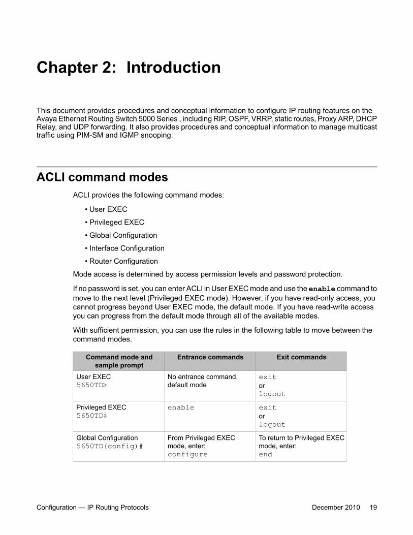
ACLI command modesACLI provides the following command modes:
• User EXEC
• Privileged EXEC
• Global Configuration
• Interface Configuration
• Router Configuration
Mode access is determined by access permission levels and password protection.
If no password is set, you can enter ACLI in User EXEC mode and use the enable command tomove to the next level (Privileged EXEC mode). However, if you have read-only access, youcannot progress beyond User EXEC mode, the default mode. If you have read-write accessyou can progress from the default mode through all of the available modes.
With sufficient permission, you can use the rules in the following table to move between thecommand modes.
Command mode andsample prompt
Entrance commands Exit commands
User EXEC5650TD>
No entrance command,default mode
exitorlogout
Privileged EXEC5650TD#
enable exitorlogout
Global Configuration5650TD(config)#
From Privileged EXECmode, enter:configure
To return to Privileged EXECmode, enter:end
Configuration — IP Routing Protocols December 2010 19
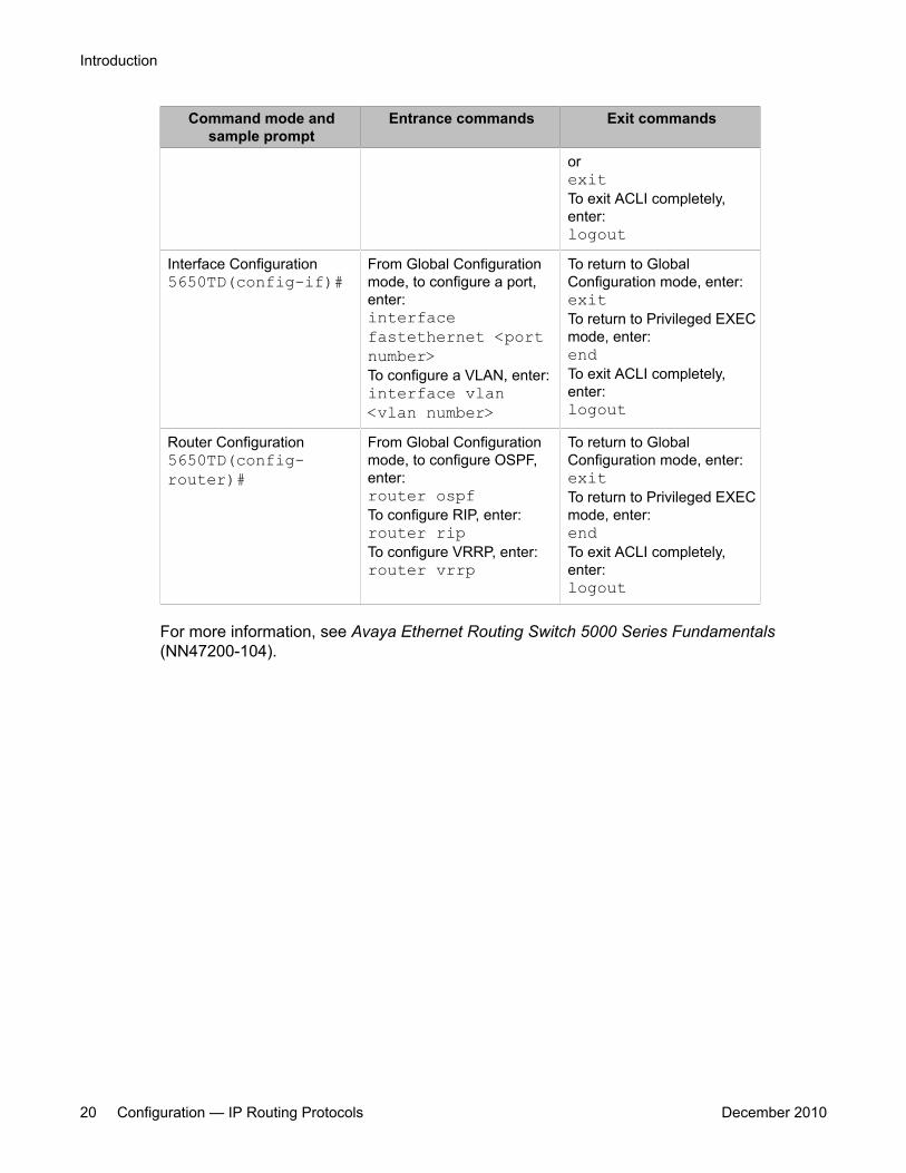
Command mode andsample prompt
Entrance commands Exit commands
orexitTo exit ACLI completely,enter:logout
Interface Configuration5650TD(config-if)#
From Global Configurationmode, to configure a port,enter:interfacefastethernet <portnumber>To configure a VLAN, enter:interface vlan<vlan number>
To return to GlobalConfiguration mode, enter:exitTo return to Privileged EXECmode, enter:endTo exit ACLI completely,enter:logout
Router Configuration5650TD(config-router)#
From Global Configurationmode, to configure OSPF,enter:router ospfTo configure RIP, enter:router ripTo configure VRRP, enter:router vrrp
To return to GlobalConfiguration mode, enter:exitTo return to Privileged EXECmode, enter:endTo exit ACLI completely,enter:logout
For more information, see Avaya Ethernet Routing Switch 5000 Series Fundamentals(NN47200-104).
Introduction
20 Configuration — IP Routing Protocols December 2010
Chapter 3: IP Routing Fundamentals
This chapter provides an introduction to IP routing and the IP routing protocols used in the Avaya EthernetRouting Switch 5000 Series.
Navigation• IP addressing overview on page 21
• IP routing on page 24
• Routing Information Protocol (RIP) on page 32
• Open Shortest Path First (OSPF) protocol on page 37
• Equal Cost MultiPath (ECMP) on page 54
• Route policies on page 54
• DHCP relay on page 56
• IP forwarding next-hop on page 60
• UDP broadcast forwarding on page 61
• Directed broadcasts on page 62
• ARP on page 62
• Static ARP on page 63
• Proxy ARP on page 63
• IP blocking for stacks on page 64
• Virtual Router Redundancy Protocol (VRRP) on page 65
IP addressing overviewAn IP version 4 (IPv4) address consists of 32 bits expressed in a dotted-decimal format(XXX.XXX.XXX.XXX). The IPv4 address space is divided into classes, with classes A, B, and Creserved for unicast addresses and accounting for 87.5 percent of the 32-bit IP address space.Class D is reserved for multicast addressing. The following table lists the breakdown of the IPaddress space by address range and mask.
Configuration — IP Routing Protocols December 2010 21

Table 1: IP address classifications
Class Address Range Mask Number ofNetworks
A 1.0.0.0 - 127.0.0.0 255.0.0.0 127
B 128.0.0.0 - 191.255.0.0 255.255.0.0 16 384
C 192.0.0.0 - 223.255.255.0 255.255.255.0 2 097 152
D 224.0.0.0 - 239.255.255.254
E 240.0.0.0 - 240.255.255.255
Note:Although technically part of Class A addressing, network 127 is reserved for loopback.
Note:Class D addresses are primarily reserved for multicast operations although theaddresses 224.0.0.5 and 224.0.0.6 are used by OSPF and 224.0.0.9 is used by RIP.
Note:Class E addresses are reserved for research purposes.
To express an IP address in dotted-decimal notation, each octet of the IP address is convertedto a decimal number and separated by decimal points. For example, the 32-bit IP address10000000 00100000 00001010 10100111 is expressed in dotted-decimal notation as128.32.10.167.
Each IP address class, when expressed in binary notation, has a different boundary pointbetween the network and host portions of the address, as shown in the following figure. Thenetwork portion is a network number field from 8 through 24 bits. The remaining 8 through 24bits identify a specific host on the network.
IP Routing Fundamentals
22 Configuration — IP Routing Protocols December 2010
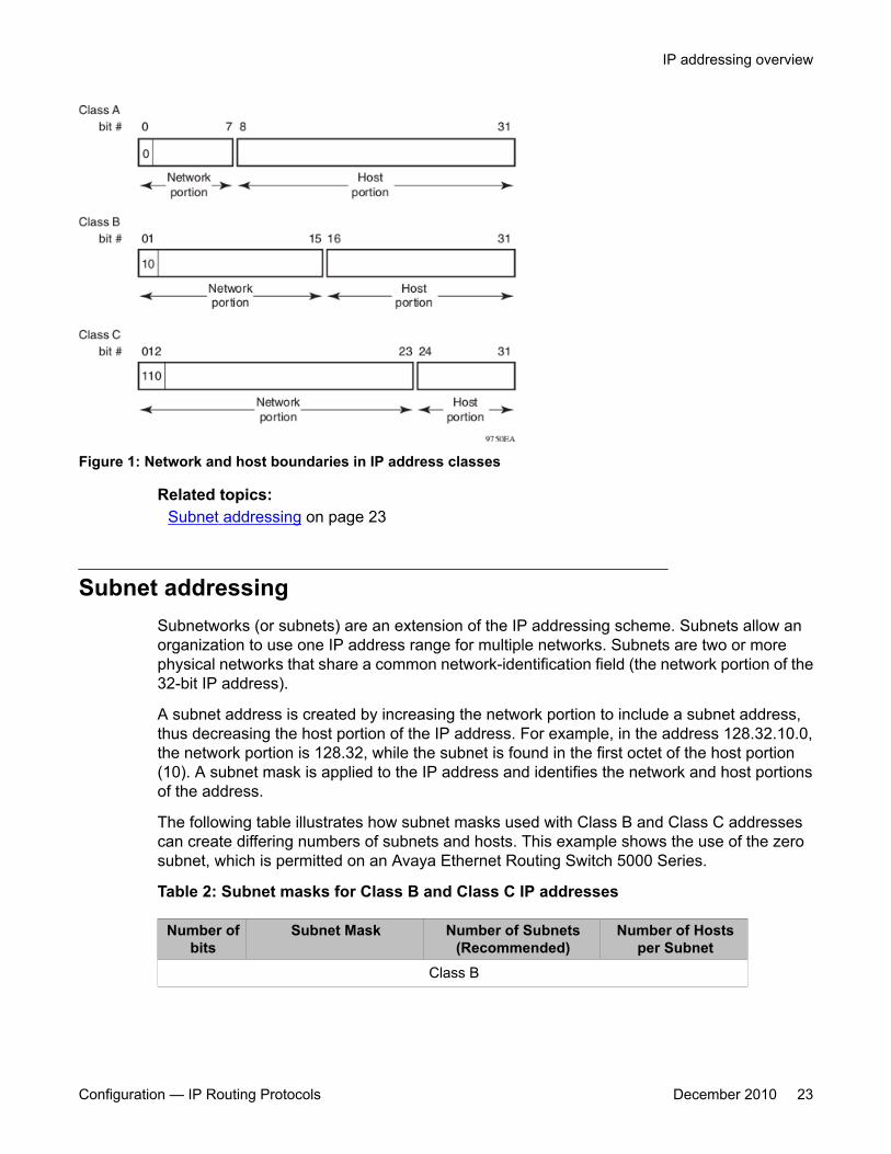
Figure 1: Network and host boundaries in IP address classes
Related topics:Subnet addressing on page 23
Subnet addressingSubnetworks (or subnets) are an extension of the IP addressing scheme. Subnets allow anorganization to use one IP address range for multiple networks. Subnets are two or morephysical networks that share a common network-identification field (the network portion of the32-bit IP address).
A subnet address is created by increasing the network portion to include a subnet address,thus decreasing the host portion of the IP address. For example, in the address 128.32.10.0,the network portion is 128.32, while the subnet is found in the first octet of the host portion(10). A subnet mask is applied to the IP address and identifies the network and host portionsof the address.
The following table illustrates how subnet masks used with Class B and Class C addressescan create differing numbers of subnets and hosts. This example shows the use of the zerosubnet, which is permitted on an Avaya Ethernet Routing Switch 5000 Series.
Table 2: Subnet masks for Class B and Class C IP addresses
Number ofbits
Subnet Mask Number of Subnets(Recommended)
Number of Hostsper Subnet
Class B
IP addressing overview
Configuration — IP Routing Protocols December 2010 23
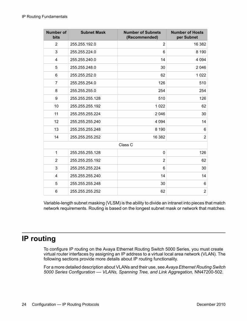
Number ofbits
Subnet Mask Number of Subnets(Recommended)
Number of Hostsper Subnet
2 255.255.192.0 2 16 382
3 255.255.224.0 6 8 190
4 255.255.240.0 14 4 094
5 255.255.248.0 30 2 046
6 255.255.252.0 62 1 022
7 255.255.254.0 126 510
8 255.255.255.0 254 254
9 255.255.255.128 510 126
10 255.255.255.192 1 022 62
11 255.255.255.224 2 046 30
12 255.255.255.240 4 094 14
13 255.255.255.248 8 190 6
14 255.255.255.252 16 382 2
Class C
1 255.255.255.128 0 126
2 255.255.255.192 2 62
3 255.255.255.224 6 30
4 255.255.255.240 14 14
5 255.255.255.248 30 6
6 255.255.255.252 62 2
Variable-length subnet masking (VLSM) is the ability to divide an intranet into pieces that matchnetwork requirements. Routing is based on the longest subnet mask or network that matches.
IP routingTo configure IP routing on the Avaya Ethernet Routing Switch 5000 Series, you must createvirtual router interfaces by assigning an IP address to a virtual local area network (VLAN). Thefollowing sections provide more details about IP routing functionality.
For a more detailed description about VLANs and their use, see Avaya Ethernet Routing Switch5000 Series Configuration –– VLANs, Spanning Tree, and Link Aggregation, NN47200-502.
IP Routing Fundamentals
24 Configuration — IP Routing Protocols December 2010
Related topics:IP routing using VLANs on page 25Local routes on page 25Local and non-local static routes on page 27Default routes on page 27Management VLAN on page 27Multinetting on page 30Brouter port on page 31
IP routing using VLANsThe Avaya Ethernet Routing Switch 5000 Series supports wire-speed IP routing betweenVLANs. To create a virtual router interface for a specified VLAN, you must associate an IPaddress with the VLAN.
The virtual router interface is not associated with any specific port. The VLAN IP address can bereached through any of the ports in the VLAN. The assigned IP address also serves as thegateway through which packets are routed out of that VLAN. Routed traffic can be forwardedto another VLAN within the switch or stack.
There is not a one-to-one correspondence between the physical port and the routable interface,because a given port can belong to multiple routable VLANs.
When the Avaya Ethernet Routing Switch 5000 Series is routing IP traffic between differentVLANs, the switch is considered to be running in Layer 3 mode; otherwise, the switch runs inLayer 2 mode. When you assign an IP address to a Layer 2 VLAN, the VLAN becomes aroutable Layer 3 VLAN. You can assign a unique IP address to each VLAN.
You can configure the global status of IP routing to be enabled or disabled on the AvayaEthernet Routing Switch 5000 Series. By default, IP routing is disabled.
All IP routing parameters can be configured on the Avaya Ethernet Routing Switch 5000 Seriesbefore routing is actually enabled on the switch.
In this release, the Avaya Ethernet Routing Switch 5000 Series supports local routes, staticroutes, and dynamic routes. With local routing, the switch automatically creates routes to eachof the local Layer 3 VLAN interfaces. With static routing, you must manually enter the routesto the destination IP addresses. With dynamic routing, routes are identified using a routingprotocol such as RIP or OSPF.
Local routesWith routing globally enabled, if you assign an IP address to a VLAN, IP routing is enabled forthat VLAN. In addition, for each IP address assigned to a VLAN interface, the Ethernet Routing
IP routing
Configuration — IP Routing Protocols December 2010 25
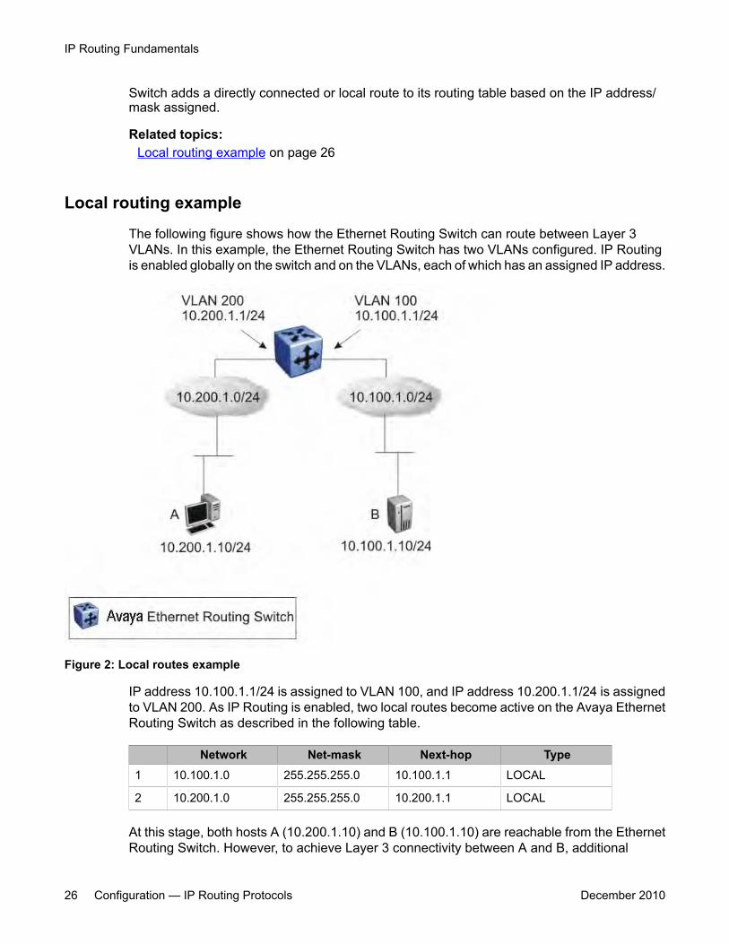
Switch adds a directly connected or local route to its routing table based on the IP address/mask assigned.
Related topics:Local routing example on page 26
Local routing example
The following figure shows how the Ethernet Routing Switch can route between Layer 3VLANs. In this example, the Ethernet Routing Switch has two VLANs configured. IP Routingis enabled globally on the switch and on the VLANs, each of which has an assigned IP address.
Figure 2: Local routes example
IP address 10.100.1.1/24 is assigned to VLAN 100, and IP address 10.200.1.1/24 is assignedto VLAN 200. As IP Routing is enabled, two local routes become active on the Avaya EthernetRouting Switch as described in the following table.
Network Net-mask Next-hop Type1 10.100.1.0 255.255.255.0 10.100.1.1 LOCAL
2 10.200.1.0 255.255.255.0 10.200.1.1 LOCAL
At this stage, both hosts A (10.200.1.10) and B (10.100.1.10) are reachable from the EthernetRouting Switch. However, to achieve Layer 3 connectivity between A and B, additional
IP Routing Fundamentals
26 Configuration — IP Routing Protocols December 2010

configuration is required. Host A must know how to reach network 10.100.1.0/24, and host Bmust know how to reach network 10.200.1.0/24.
On host A, you must configure a route to network 10.100.1.0/24 through 10.200.1.1, orconfigure 10.200.1.1 as the default gateway for the host.
On host B, you must configure a route to network 10.200.1.0/24 through 10.100.1.1, orconfigure 10.100.1.1 as the default gateway for the host.
With these routes configured, the Ethernet Routing Switch can perform inter-VLAN routing,and packets can flow between hosts A and B.
Local and non-local static routesAfter you create routable VLANs through IP address assignment, you can create static routes.With static routes, you can manually create specific routes to destination IP addresses. In thisrelease, the Ethernet Routing Switch supports local and non-local static routes. Local routeshave a next-hop that is on a directly connected network, while non-local routes have a next-hop that is not on a directly connected network. Non-local static routes are useful in situationswhere there are multiple paths to a network and the number of static routes can be reducedby using only one route with a remote gateway.
Static routes are not easily scalable. Thus, in a large or growing network this type of routemanagement may not be optimal. Also, static routes do not have the capacity to determine thefailure of paths. Thus, a router can still attempt to use a path after it has failed.
Default routesDefault routes specify a route to all networks for which there are no explicit routes in theForwarding Information Base or the routing table. This static default route is a route to thenetwork address 0.0.0.0 as defined by the Institute of Electrical and Electronics Engineers(IEEE) Request for Comment (RFC) 1812 standard.
The Ethernet Routing Switch uses the default route 0.0.0.0/0.0.0.0 for all Layer 3 traffic thatdoes not match a specific route. This traffic is forwarded to the next-hop IP address specified inthe default route.
Management VLANWith IP routing enabled on the switch or stack, you can use any of the virtual router IPaddresses for device management over IP. Any routable Layer 3 VLAN can carry themanagement traffic, including Telnet, Web, Simple Network Management Protocol (SNMP),BootP and Trivial File Transfer Protocol (TFTP). Without routing enabled, the management
IP routing
Configuration — IP Routing Protocols December 2010 27
VLAN is reachable only through the switch or stack IP address, and only through ports thatare members of the management VLAN. The management VLAN always exists on the switchand cannot be removed.
When routing is enabled on the Avaya Ethernet Routing Switch 5000 Series switches, themanagement VLAN behaves similar to other routable VLANs. The IP address is reachablethrough any virtual router interface, as long as a route is available.
Related topics:Management route on page 28
Management route
On the Ethernet Routing Switch, you can configure a management route from the ManagementVLAN to a particular subnet. The management route is a static route that allows incomingmanagement connections from the remote network to the management VLAN.
The management route transports traffic between the specified destination network and theManagement VLAN only. It does not carry inter-VLAN routed traffic from the other Layer 3VLANs to the destination network. This provides a management path to the router that isinaccessible from the other Layer 3 VLANs. While you can access the management VLANfrom all static routes, other static routes cannot route traffic to the management route.
To allow connectivity through a management route, IP Routing must also be enabled globallyand on the management VLAN interface.
The management route next-hop IP address must reside in the same network as the IP addressof the switch or stack and it must be directly reachable.
The following figure shows an example of a management route allowing access to themanagement VLAN interface.
IP Routing Fundamentals
28 Configuration — IP Routing Protocols December 2010
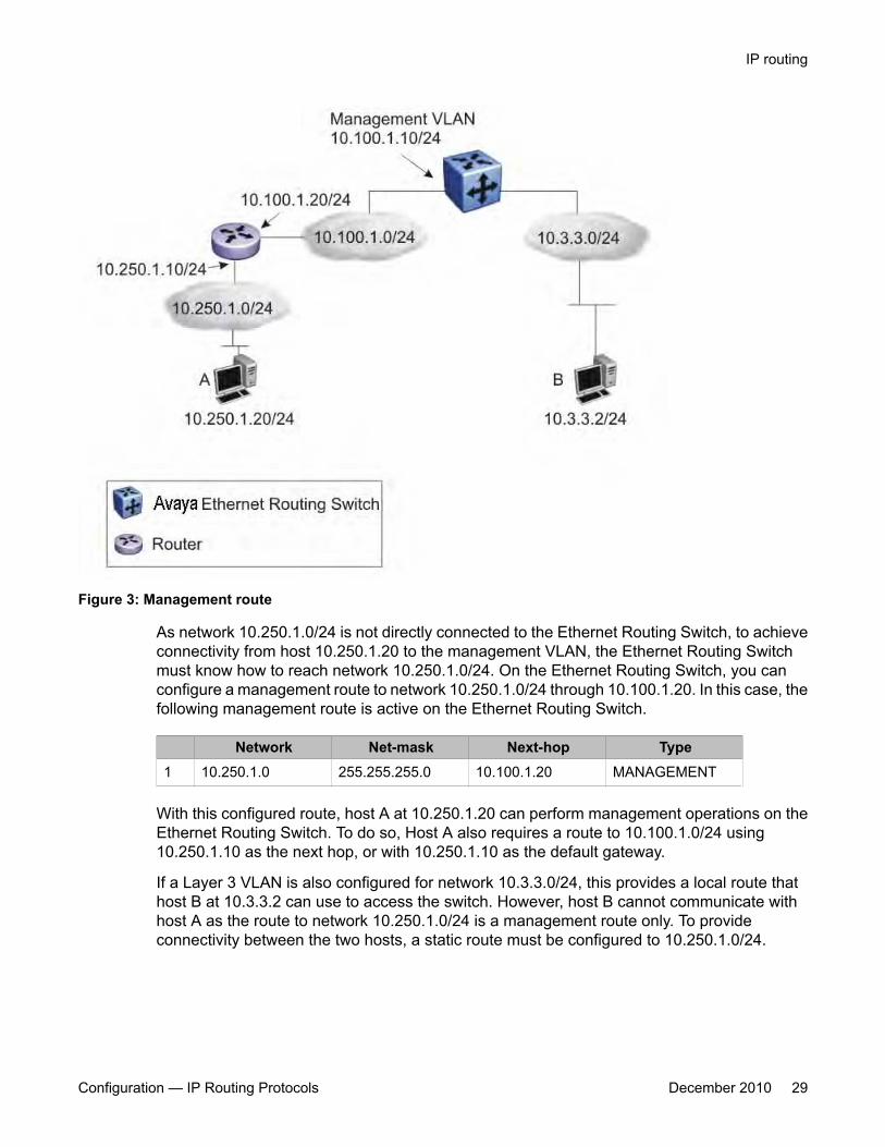
Figure 3: Management route
As network 10.250.1.0/24 is not directly connected to the Ethernet Routing Switch, to achieveconnectivity from host 10.250.1.20 to the management VLAN, the Ethernet Routing Switchmust know how to reach network 10.250.1.0/24. On the Ethernet Routing Switch, you canconfigure a management route to network 10.250.1.0/24 through 10.100.1.20. In this case, thefollowing management route is active on the Ethernet Routing Switch.
Network Net-mask Next-hop Type1 10.250.1.0 255.255.255.0 10.100.1.20 MANAGEMENT
With this configured route, host A at 10.250.1.20 can perform management operations on theEthernet Routing Switch. To do so, Host A also requires a route to 10.100.1.0/24 using10.250.1.10 as the next hop, or with 10.250.1.10 as the default gateway.
If a Layer 3 VLAN is also configured for network 10.3.3.0/24, this provides a local route thathost B at 10.3.3.2 can use to access the switch. However, host B cannot communicate withhost A as the route to network 10.250.1.0/24 is a management route only. To provideconnectivity between the two hosts, a static route must be configured to 10.250.1.0/24.
IP routing
Configuration — IP Routing Protocols December 2010 29

MultinettingThe Avaya Ethernet Routing Switch 5000 Series supports the definition and configuration ofup to eight secondary interfaces on each VLAN (multinetting). With IP multinetting, you canassociate multiple IP subnets with one VLAN. That is, connected hosts can belong to differentIP subnets on the same VLAN.
Multinetting can be configured using ACLI or Enterprise Device Manager.
The following diagram illustrates a network with configured IP multinetting.
Figure 4: Network with Multinetting
You can configure a static route with the next hop on the secondary interface. You can alsoadd static ARP for a given IP address in the same subnet of a secondary interface.
Here are some limitations when you are working with secondary interfaces:
• you can have a maximum of eight secondary interfaces on each VLAN
• you can have a total maximum of 256 IP interfaces (including primary and secondary)
• all of the secondary interfaces on a VLAN are enabled or disabled together. There is noprovision for configuring the administrative state of the secondary IP interfacesindividually.
IP Routing Fundamentals
30 Configuration — IP Routing Protocols December 2010

• dynamic routing is not available for secondary IP interfaces
• secondary interfaces are not supported on brouters
• a primary IP interface must be in place before secondary IP interfaces can be added;secondary interfaces must be deleted before you can delete the primary
If secondary interfaces are configured on the management VLAN, routing cannot be disabledglobally or on the management VLAN. Secondary IP interfaces on the management VLAN arepurged from NVRAM when
• a unit leaves the stack and the switch does not have a manually configured IP
• the switch fails to get the IP address through the BootP mode
The following are not supported on secondary interfaces:
• DHCP
• Proxy ARP
• UDP broadcast
• IPFIX
• VRRP, OSPF, RIP
Brouter portThe Avaya Ethernet Routing Switch 5000 Series supports the configuration of brouter ports.A brouter port is a single-port VLAN that can route IP packets as well as bridge all non-routable traffic. The difference between a brouter port and a standard IP protocol-based VLANconfigured for routing is that the routing interface of the brouter port is not subject to thespanning tree state of the port. A brouter port can be in the blocking state for non-routabletraffic and still be able to route IP traffic. This feature removes any interruptions caused bySpanning Tree Protocol recalculations in routed traffic. A brouter port is actually a one-portVLAN; therefore, each brouter port decreases the number of available VLANs by one and usesone VLAN ID.
When a brouter port is created, the following actions also take place on the switch:
• A port-based VLAN is created.
• The brouter port is added to the new port-based VLAN.
• The PVID of the brouter port is changed to the VLAN ID of the new VLAN.
• The STP participation of the brouter port is disabled.
• An IP address is assigned to the brouter VLAN.
IP routing
Configuration — IP Routing Protocols December 2010 31
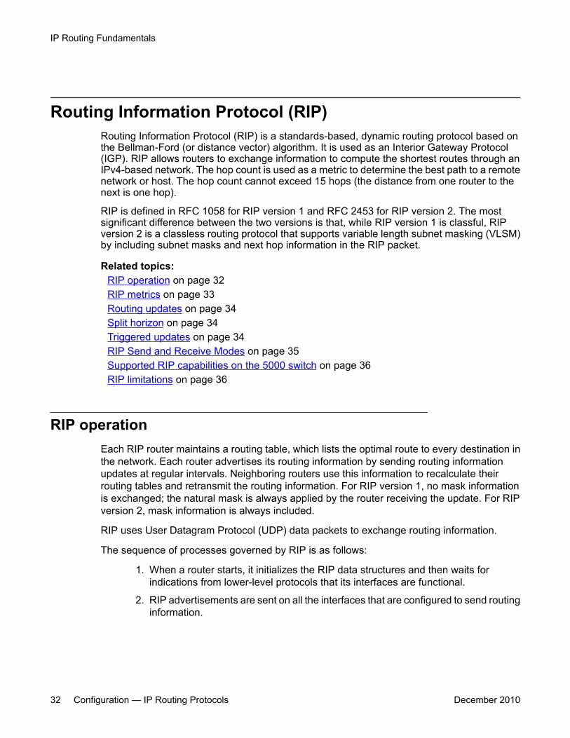
Routing Information Protocol (RIP)Routing Information Protocol (RIP) is a standards-based, dynamic routing protocol based onthe Bellman-Ford (or distance vector) algorithm. It is used as an Interior Gateway Protocol(IGP). RIP allows routers to exchange information to compute the shortest routes through anIPv4-based network. The hop count is used as a metric to determine the best path to a remotenetwork or host. The hop count cannot exceed 15 hops (the distance from one router to thenext is one hop).
RIP is defined in RFC 1058 for RIP version 1 and RFC 2453 for RIP version 2. The mostsignificant difference between the two versions is that, while RIP version 1 is classful, RIPversion 2 is a classless routing protocol that supports variable length subnet masking (VLSM)by including subnet masks and next hop information in the RIP packet.
Related topics:RIP operation on page 32RIP metrics on page 33Routing updates on page 34Split horizon on page 34Triggered updates on page 34RIP Send and Receive Modes on page 35Supported RIP capabilities on the 5000 switch on page 36RIP limitations on page 36
RIP operationEach RIP router maintains a routing table, which lists the optimal route to every destination inthe network. Each router advertises its routing information by sending routing informationupdates at regular intervals. Neighboring routers use this information to recalculate theirrouting tables and retransmit the routing information. For RIP version 1, no mask informationis exchanged; the natural mask is always applied by the router receiving the update. For RIPversion 2, mask information is always included.
RIP uses User Datagram Protocol (UDP) data packets to exchange routing information.
The sequence of processes governed by RIP is as follows:
1. When a router starts, it initializes the RIP data structures and then waits forindications from lower-level protocols that its interfaces are functional.
2. RIP advertisements are sent on all the interfaces that are configured to send routinginformation.
IP Routing Fundamentals
32 Configuration — IP Routing Protocols December 2010
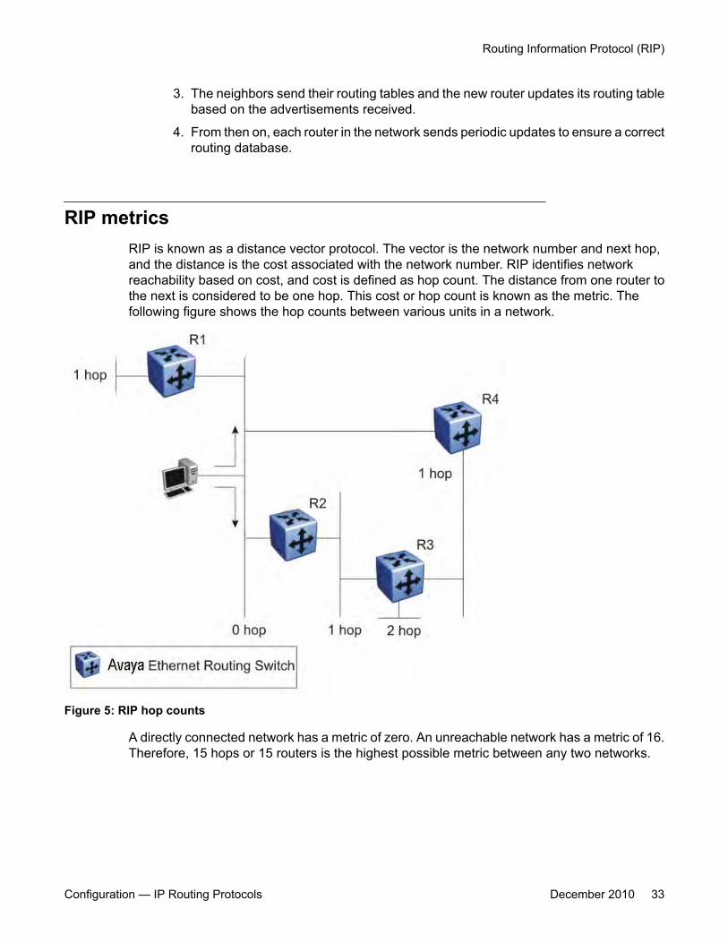
3. The neighbors send their routing tables and the new router updates its routing tablebased on the advertisements received.
4. From then on, each router in the network sends periodic updates to ensure a correctrouting database.
RIP metricsRIP is known as a distance vector protocol. The vector is the network number and next hop,and the distance is the cost associated with the network number. RIP identifies networkreachability based on cost, and cost is defined as hop count. The distance from one router tothe next is considered to be one hop. This cost or hop count is known as the metric. Thefollowing figure shows the hop counts between various units in a network.
Figure 5: RIP hop counts
A directly connected network has a metric of zero. An unreachable network has a metric of 16.Therefore, 15 hops or 15 routers is the highest possible metric between any two networks.
Routing Information Protocol (RIP)
Configuration — IP Routing Protocols December 2010 33

Routing updatesEach RIP router advertises routing information updates out of all RIP-enabled interfaces atregular intervals (30 seconds by default). You can configure this interval using the update timerparameter. The routing updates contain information about known networks and the distances(hop count) associated with each. For RIP version 1, no mask information is exchanged; thenatural mask is always applied by the router receiving the update. With RIP version 2, maskinformation is always included.
If a RIP router does not receive an update from another RIP router within a timeout period (180seconds by default), it deletes the routes advertised by the nonupdating router from its routingtable. You can configure this interval using the timeout interval parameter.
The router keeps aged routes from nonupdating routers temporarily in a garbage list andcontinues to advertise them with a metric of infinity (16) for a holddown period (120 secondsby default), so that neighbors know that the routes are unreachable. You can configure thisinterval using the holddown timer parameter. If a valid update for a garbage route is receivedwithin the holddown period, the router adds the route back into its routing table. If no updateis received, the router completely deletes all garbage list entries for the nonupdating router.
Split horizonTo prevent routing loops, RIP uses the mechanism of split horizon, with or without poisonreverse. Simple split horizon means that IP routes learned from a neighbor are not advertisedback in updates to that neighbor. Split horizon with poison reverse means that these routesare advertised back to the neighbor, but they are “poisoned” with a metric of 16, whichrepresents infinite hops in the network. The receiver neighbor therefore ignores this route.
By default, RIP split horizon is enabled without poison reverse.
Triggered updatesTo promote fast convergence, RIP also supports a triggered updates option. With triggeredupdates enabled, a router sends update messages whenever it changes the metric for a route,even if it is not yet time for a regular update message.
IP Routing Fundamentals
34 Configuration — IP Routing Protocols December 2010
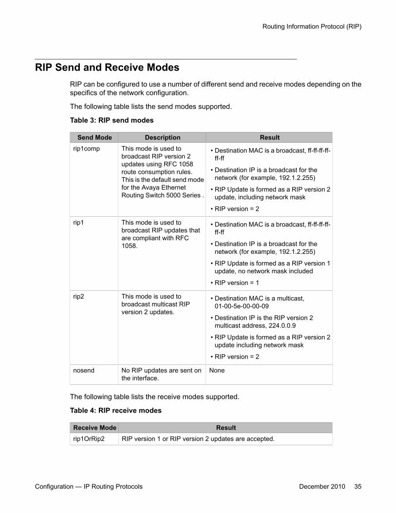
RIP Send and Receive ModesRIP can be configured to use a number of different send and receive modes depending on thespecifics of the network configuration.
The following table lists the send modes supported.
Table 3: RIP send modes
Send Mode Description Resultrip1comp This mode is used to
broadcast RIP version 2updates using RFC 1058route consumption rules.This is the default send modefor the Avaya EthernetRouting Switch 5000 Series .
• Destination MAC is a broadcast, ff-ff-ff-ff-ff-ff
• Destination IP is a broadcast for thenetwork (for example, 192.1.2.255)
• RIP Update is formed as a RIP version 2update, including network mask
• RIP version = 2
rip1 This mode is used tobroadcast RIP updates thatare compliant with RFC1058.
• Destination MAC is a broadcast, ff-ff-ff-ff-ff-ff
• Destination IP is a broadcast for thenetwork (for example, 192.1.2.255)
• RIP Update is formed as a RIP version 1update, no network mask included
• RIP version = 1
rip2 This mode is used tobroadcast multicast RIPversion 2 updates.
• Destination MAC is a multicast,01-00-5e-00-00-09
• Destination IP is the RIP version 2multicast address, 224.0.0.9
• RIP Update is formed as a RIP version 2update including network mask
• RIP version = 2
nosend No RIP updates are sent onthe interface.
None
The following table lists the receive modes supported.
Table 4: RIP receive modes
Receive Mode Resultrip1OrRip2 RIP version 1 or RIP version 2 updates are accepted.
Routing Information Protocol (RIP)
Configuration — IP Routing Protocols December 2010 35
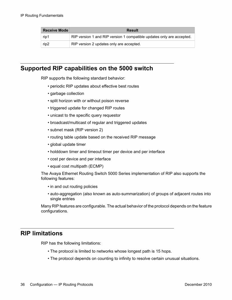
Receive Mode Resultrip1 RIP version 1 and RIP version 1 compatible updates only are accepted.
rip2 RIP version 2 updates only are accepted.
Supported RIP capabilities on the 5000 switchRIP supports the following standard behavior:
• periodic RIP updates about effective best routes
• garbage collection
• split horizon with or without poison reverse
• triggered update for changed RIP routes
• unicast to the specific query requestor
• broadcast/multicast of regular and triggered updates
• subnet mask (RIP version 2)
• routing table update based on the received RIP message
• global update timer
• holddown timer and timeout timer per device and per interface
• cost per device and per interface
• equal cost multipath (ECMP)
The Avaya Ethernet Routing Switch 5000 Series implementation of RIP also supports thefollowing features:
• in and out routing policies
• auto-aggregation (also known as auto-summarization) of groups of adjacent routes intosingle entries
Many RIP features are configurable. The actual behavior of the protocol depends on the featureconfigurations.
RIP limitationsRIP has the following limitations:
• The protocol is limited to networks whose longest path is 15 hops.
• The protocol depends on counting to infinity to resolve certain unusual situations.
IP Routing Fundamentals
36 Configuration — IP Routing Protocols December 2010
• The protocol uses fixed metrics (the hop number) to compare alternative routes, asopposed to real-time parameters such as measured delay, reliability, or load.
• RIP does not support address-less links.
Open Shortest Path First (OSPF) protocolOpen Shortest Path First (OSPF) is a classless Interior Gateway Protocol (IGP) that distributesrouting information between routers belonging to a single autonomous system (AS). An OSPFAS is generally defined as a group of routers in a network that run OSPF and that operateunder the same administration. Intended for use in large networks, OSPF is a link-state protocolthat supports variable length subnet masking (VLSM) and tagging of externally-derived routinginformation.
Important:The Avaya Ethernet Routing Switch 5000 Series implementation of OSPF only supportsbroadcast and passive interfaces. Point-to-point and NBMA interfaces are not supported.
Related topics:Overview on page 37Autonomous system and areas on page 38ASBR and external router advertisements on page 40OSPF neighbors on page 41Designated routers on page 41OSPF operation on page 42OSPF router advertisements on page 42Router types on page 43LSA types on page 43Area types on page 45OSPF virtual link on page 48OSPF host route on page 50OSPF interfaces on page 50OSPF packets on page 51OSPF metrics on page 52Automatic router ID change in a stack on page 52OSPF security mechanisms on page 53
OverviewIn an OSPF network, each router maintains a link-state database that describes the topology ofthe autonomous system (AS). The database contains the local state for each router in the AS,
Open Shortest Path First (OSPF) protocol
Configuration — IP Routing Protocols December 2010 37
including usable interfaces and reachable neighbors. Each router periodically checks forchanges in its local state and shares detected changes by flooding link-state advertisements(LSA) throughout the AS. Routers synchronize their topological databases based on thesharing of information from LSAs.
From the topological database, each router constructs a shortest-path tree, with itself as theroot. The shortest-path tree gives the optimal route to each destination in the AS. Routinginformation from outside the AS appears on the tree as leaves.
In large networks, OSPF offers the following benefits:
• Fast convergence
When the network topology changes, OSPF recalculates routes quickly.
• Minimal routing protocol traffic
Unlike distance vector routing protocols, such as RIP, OSPF generates a minimum ofrouting protocol traffic.
• Load sharing
OSPF provides support for equal-cost multipath routing. If several equal-cost routes to adestination exist, traffic is distributed equally among them.
• Scalable
Because OSPF does not use hop count in its calculation, the routing domain is scalable.
OSPF routes IP traffic based on the destination IP address, subnet mask, and IP TOS.
The Ethernet Routing Switch 5000 Series implementation of OSPF does not support TOS-based routing.
Autonomous system and areasIn large OSPF networks with many routers and networks, the link-state database (LSDB) androuting table on each router can become excessively large. Large route tables and LSDBsconsume memory. In addition, the processing of additional LSAs puts added strain on the CPUto make forwarding decisions. To reduce these undesired effects, an OSPF network can bedivided into subdomains called areas. Each area comprises a number of OSPF routers thathave the same area ID. Subdividing the AS into areas significantly reduces the amount ofrouting protocol traffic compared to treating the entire AS as a single link-state domain.
When a network is divided into multiple areas, each router within an area maintains an LSDBonly for the area to which it belongs. Each area is identified by a unique 32-bit area ID,expressed in IP address format (x.x.x.x). Area 0.0.0.0 is known as the backbone area anddistributes routing information to all other areas.
Within the AS, packets are routed based on their source and destination addresses. If thesource and destination of a packet reside in the same area, intra-area routing is used. Intra-
IP Routing Fundamentals
38 Configuration — IP Routing Protocols December 2010
area routing protects the area from bad routing information because no routing informationobtained from outside the area can be used.
If the source and destination of a packet reside in different areas, inter-area routing is used.Inter-area routing must pass through the backbone area.
Related topics:ABR on page 39Backbone area on page 39
ABR
A router attached to two or more areas inside an OSPF network is identified as an Area BorderRouter (ABR). Each ABR maintains a separate topological database for each connected area.ABRs play an important role in OSPF networks by condensing the amount of disseminatedOSPF information from one area to another. When the AS is divided into multiple areas, eachnonbackbone area must be attached to the backbone area through an (ABR).
For routers that are internal to an area (identified as internal routers), the impact of a topologychange is localized to the area in which it occurs. However, ABRs must maintain an LSDB foreach area to which they belong. ABRs advertise changes in topology from one area to anotherby advertising summary LSAs.
Backbone area
The backbone area connects nonbackbone areas to each other. Traffic forwarded from onearea to another must travel through the backbone. The backbone topology dictates the pathsused between areas. The topology of the backbone area is invisible to other areas and thebackbone has no knowledge of the topology of nonbackbone areas.
The area ID 0.0.0.0 is reserved for the backbone area.
Area border routers (ABR) cannot learn OSPF routes unless they have a connection to thebackbone. Inter-area paths are selected by examining the routing table summaries for eachconnected ABR.
In inter-area routing, a packet travels along three contiguous paths:
1. First, the packet follows an intra-area path from the source to an ABR, whichprovides the link to the backbone.
2. From the source ABR, the packet travels through the backbone toward thedestination area ABR.
3. At the destination area ABR, the packet takes another intra-area path to thedestination.
Open Shortest Path First (OSPF) protocol
Configuration — IP Routing Protocols December 2010 39
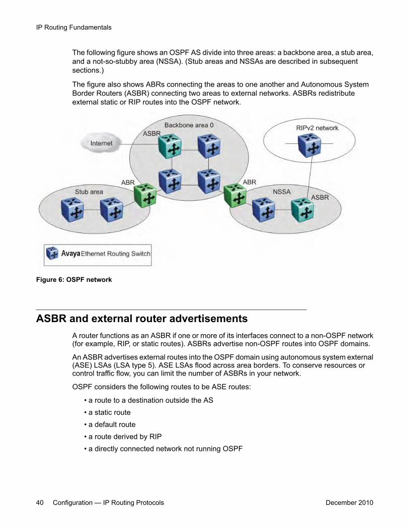
The following figure shows an OSPF AS divide into three areas: a backbone area, a stub area,and a not-so-stubby area (NSSA). (Stub areas and NSSAs are described in subsequentsections.)
The figure also shows ABRs connecting the areas to one another and Autonomous SystemBorder Routers (ASBR) connecting two areas to external networks. ASBRs redistributeexternal static or RIP routes into the OSPF network.
Figure 6: OSPF network
ASBR and external router advertisementsA router functions as an ASBR if one or more of its interfaces connect to a non-OSPF network(for example, RIP, or static routes). ASBRs advertise non-OSPF routes into OSPF domains.
An ASBR advertises external routes into the OSPF domain using autonomous system external(ASE) LSAs (LSA type 5). ASE LSAs flood across area borders. To conserve resources orcontrol traffic flow, you can limit the number of ASBRs in your network.
OSPF considers the following routes to be ASE routes:
• a route to a destination outside the AS• a static route• a default route• a route derived by RIP• a directly connected network not running OSPF
IP Routing Fundamentals
40 Configuration — IP Routing Protocols December 2010
Related topics:External route metrics on page 41
External route metrics
When an ASBR imports external routes, it imports OSPF route information using external type1 or type 2 metrics. With external type 1 metrics, OSPF calculates the total cost by adding theexternal metric value and the internal cost to the ASBR. For external type 2 metrics, only theinternal OSPF cost to the ASBR is used in the routing decision. You can specify the metric typeto use by configuring a route policy. For more information, see Route policies on page 54.
OSPF neighborsIn an OSPF broadcast network, any two routers that have an interface to the same networkare neighbors. OSPF routers use the Hello Protocol to dynamically discover and maintainneighbor relationships.
Periodically, OSPF routers send Hello packets over all interfaces to the AllSPFRoutersmulticast address. These Hello packets include the following information:
• router priority
• router Hello Timer and Dead Timer values
• list of routers that sent the router Hello packets on this interface
• router choice for designated router (DR) and backup designated router (BDR)
Bidirectional communication is determined when a router discovers itself listed in its neighborHello packet.
Designated routersTo form an adjacency, two OSPF routers perform a database exchange process to synchronizetheir topological databases. When their databases are synchronized, the routers are said tobe fully adjacent.
To limit the amount of routing protocol traffic, OSPF routers use the Hello Protocol to elect adesignated router (DR) and a backup designated router (BDR) on each multiaccess network.Instead of neighboring routers forming adjacencies and swapping link-state information (whichon a large network can mean significant routing protocol traffic), all routers on the network formadjacencies with the DR and the BDR only, and send link-state information only to them. TheDR redistributes this information to every other adjacent router.
Open Shortest Path First (OSPF) protocol
Configuration — IP Routing Protocols December 2010 41
The BDR receives link-state information from all routers on the network and listens foracknowledgements. If the DR fails, the BDR can transition quickly to the role of DR becauseits routing tables are up to date.
OSPF operationOn broadcast multiaccess networks, the sequence of processes governed by OSPF is asfollows:
1. When a router starts, it initializes the OSPF data structures and then waits forindications from lower-level protocols that the router interfaces are functional.
2. The router dynamically detects neighbors by sending and receiving Hello packetsto the AllSPFRouters multicast address.
3. Using the Hello Protocol, a designated router (DR) and backup designated router(BDR) are elected for the network.
4. Each router forms an adjacency and exchanges database information only with theDR and the BDR.
5. The DR floods LSAs containing information about each router and its neighborsthroughout the area to ensure that all routers in the area have an identicaltopological database.
6. From this database each router uses the OSPF routing algorithm (Dijkstra'salgorithm) to calculate a shortest-path tree, with itself as root. This shortest-pathtree in turn yields a routing table for the protocol.
7. After the network has converged, each OSPF router continues to periodically floodHellos to maintain neighbor relationships. And at longer intervals, LSAs areretransmitted throughout the area. In addition, routers forwards LSAs to the DR ifthey detect a change in the state of a router or a link (that is, up or down). Uponreceipt of an LSA, the DR can then flood the update to all routers in the area,enabling quick detection of dead routers on the network.
OSPF router advertisementsA destination in an OSPF router advertisement is expressed as an IP address and a variable-length mask. Together, the address and the mask indicate the range of destinations to whichthe advertisement applies.
Because OSPF can specify a range of networks, it can send one summary advertisement thatrepresents multiple destinations. For example, a summary advertisement for the destination
IP Routing Fundamentals
42 Configuration — IP Routing Protocols December 2010
128.185.0.0 with a mask of 255.255.0.0 describes a single route to destinations 128.185.0.0to 128.185.255.255.
Router typesAs mentioned in preceding sections, routers in an OSPF network can have various rolesdepending on how you configure them. The following table describes the router types you canconfigure in an OSPF network.
Table 5: Router types in an OSPF network
Router type DescriptionAS boundary router(ASBR)
A router attached at the edge of an OSPF network is called anASBR. Any router that distributes static routes or RIP routes intoOSPF is considered an ASBR. The ASBR forwards external routesinto the OSPF domain. In this way, routers inside the OSPFnetwork learn about destinations outside their domain.
Area border router(ABR)
A router attached to two or more areas inside an OSPF network isconsidered an ABR. ABRs play an important role in OSPFnetworks by condensing the amount of disseminated OSPFinformation.
Internal router (IR) A router that has interfaces only within a single area inside anOSPF network is considered an IR. Unlike ABRs, IRs havetopological information only about the area in which they arecontained.
Designated router(DR)
In a broadcast network, a single router is elected to be the DR forthat network. A DR ensures that all routers on the network aresynchronized and advertises the network to the rest of the AS.
Backup designatedrouter (BDR)
A BDR is elected in addition to the DR and, if the DR fails, canassume the DR role quickly.
LSA typesAfter the network has converged, OSPF does not require each router to keep sending its entireLSDB to its neighbors. Instead, each OSPF router floods only link-state change information inthe form of LSAs throughout the area or AS. LSAs typically contain information about the routerand its neighbors and are generated periodically to ensure connectivity or are generated by achange in state of the router or a link (that is, up or down).
The following table displays the seven LSA types exchanged between OSPF routers.
Open Shortest Path First (OSPF) protocol
Configuration — IP Routing Protocols December 2010 43
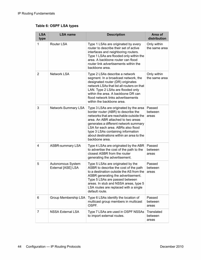
Table 6: OSPF LSA types
LSAtype
LSA name Description Area ofdistribution
1 Router LSA Type 1 LSAs are originated by everyrouter to describe their set of activeinterfaces and neighboring routers.Type 1 LSAs are flooded only within thearea. A backbone router can floodrouter link advertisements within thebackbone area.
Only withinthe same area
2 Network LSA Type 2 LSAs describe a networksegment. In a broadcast network, thedesignated router (DR) originatesnetwork LSAs that list all routers on thatLAN. Type 2 LSAs are flooded onlywithin the area. A backbone DR canflood network links advertisementswithin the backbone area.
Only withinthe same area
3 Network-Summary LSA Type 3 LSAs are originated by the areaborder router (ABR) to describe thenetworks that are reachable outside thearea. An ABR attached to two areasgenerates a different network summaryLSA for each area. ABRs also floodtype 3 LSAs containing informationabout destinations within an area to thebackbone area.
Passedbetweenareas
4 ASBR-summary LSA Type 4 LSAs are originated by the ABRto advertise the cost of the path to theclosest ASBR from the routergenerating the advertisement.
Passedbetweenareas
5 Autonomous SystemExternal [ASE] LSA
Type 5 LSAs are originated by theASBR to describe the cost of the pathto a destination outside the AS from theASBR generating the advertisement.Type 5 LSAs are passed betweenareas. In stub and NSSA areas, type 5LSA routes are replaced with a singledefault route.
Passedbetweenareas
6 Group Membership LSA Type 6 LSAs identify the location ofmulticast group members in multicastOSPF.
Passedbetweenareas
7 NSSA External LSA Type 7 LSAs are used in OSPF NSSAsto import external routes.
Translatedbetweenareas
IP Routing Fundamentals
44 Configuration — IP Routing Protocols December 2010
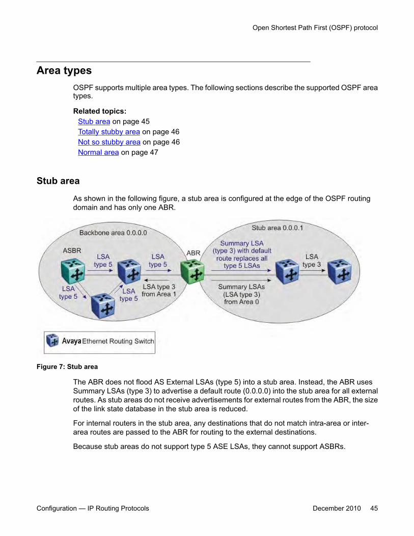
Area typesOSPF supports multiple area types. The following sections describe the supported OSPF areatypes.
Related topics:Stub area on page 45Totally stubby area on page 46Not so stubby area on page 46Normal area on page 47
Stub area
As shown in the following figure, a stub area is configured at the edge of the OSPF routingdomain and has only one ABR.
Figure 7: Stub area
The ABR does not flood AS External LSAs (type 5) into a stub area. Instead, the ABR usesSummary LSAs (type 3) to advertise a default route (0.0.0.0) into the stub area for all externalroutes. As stub areas do not receive advertisements for external routes from the ABR, the sizeof the link state database in the stub area is reduced.
For internal routers in the stub area, any destinations that do not match intra-area or inter-area routes are passed to the ABR for routing to the external destinations.
Because stub areas do not support type 5 ASE LSAs, they cannot support ASBRs.
Open Shortest Path First (OSPF) protocol
Configuration — IP Routing Protocols December 2010 45
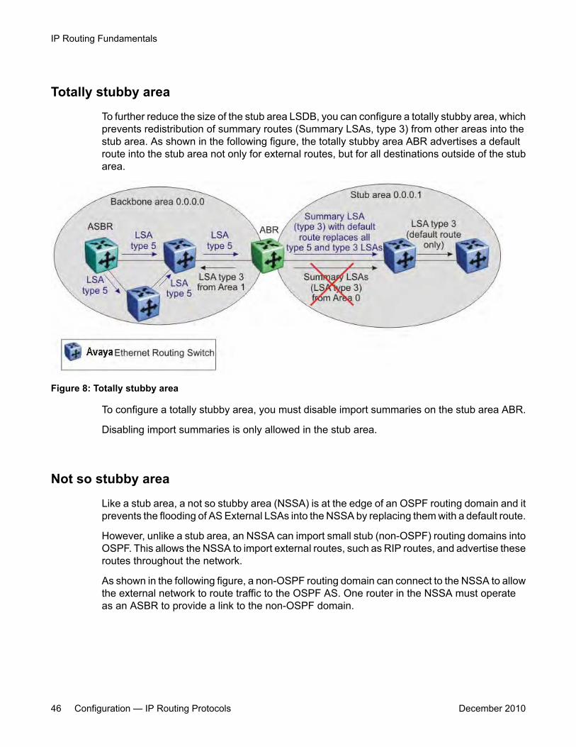
Totally stubby area
To further reduce the size of the stub area LSDB, you can configure a totally stubby area, whichprevents redistribution of summary routes (Summary LSAs, type 3) from other areas into thestub area. As shown in the following figure, the totally stubby area ABR advertises a defaultroute into the stub area not only for external routes, but for all destinations outside of the stubarea.
Figure 8: Totally stubby area
To configure a totally stubby area, you must disable import summaries on the stub area ABR.
Disabling import summaries is only allowed in the stub area.
Not so stubby area
Like a stub area, a not so stubby area (NSSA) is at the edge of an OSPF routing domain and itprevents the flooding of AS External LSAs into the NSSA by replacing them with a default route.
However, unlike a stub area, an NSSA can import small stub (non-OSPF) routing domains intoOSPF. This allows the NSSA to import external routes, such as RIP routes, and advertise theseroutes throughout the network.
As shown in the following figure, a non-OSPF routing domain can connect to the NSSA to allowthe external network to route traffic to the OSPF AS. One router in the NSSA must operateas an ASBR to provide a link to the non-OSPF domain.
IP Routing Fundamentals
46 Configuration — IP Routing Protocols December 2010
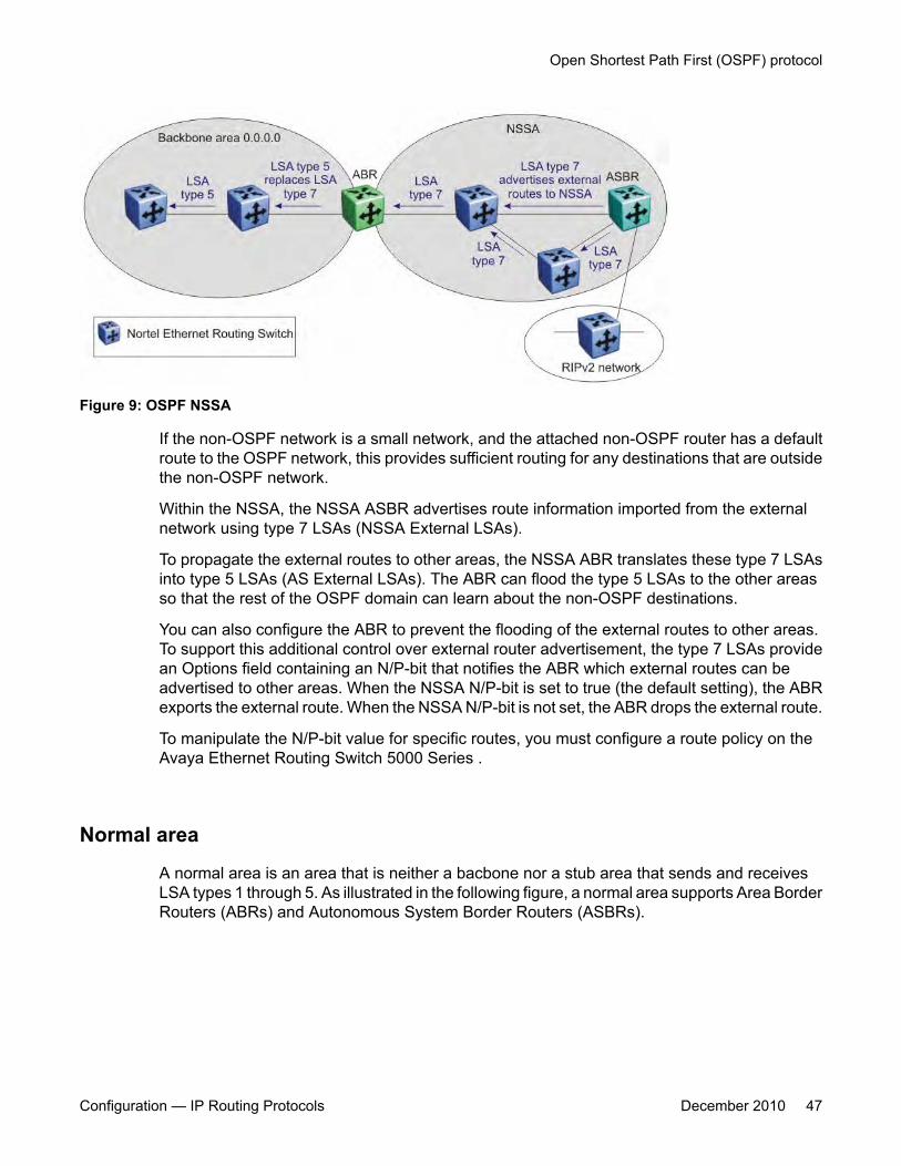
Figure 9: OSPF NSSA
If the non-OSPF network is a small network, and the attached non-OSPF router has a defaultroute to the OSPF network, this provides sufficient routing for any destinations that are outsidethe non-OSPF network.
Within the NSSA, the NSSA ASBR advertises route information imported from the externalnetwork using type 7 LSAs (NSSA External LSAs).
To propagate the external routes to other areas, the NSSA ABR translates these type 7 LSAsinto type 5 LSAs (AS External LSAs). The ABR can flood the type 5 LSAs to the other areasso that the rest of the OSPF domain can learn about the non-OSPF destinations.
You can also configure the ABR to prevent the flooding of the external routes to other areas.To support this additional control over external router advertisement, the type 7 LSAs providean Options field containing an N/P-bit that notifies the ABR which external routes can beadvertised to other areas. When the NSSA N/P-bit is set to true (the default setting), the ABRexports the external route. When the NSSA N/P-bit is not set, the ABR drops the external route.
To manipulate the N/P-bit value for specific routes, you must configure a route policy on theAvaya Ethernet Routing Switch 5000 Series .
Normal area
A normal area is an area that is neither a bacbone nor a stub area that sends and receivesLSA types 1 through 5. As illustrated in the following figure, a normal area supports Area BorderRouters (ABRs) and Autonomous System Border Routers (ASBRs).
Open Shortest Path First (OSPF) protocol
Configuration — IP Routing Protocols December 2010 47
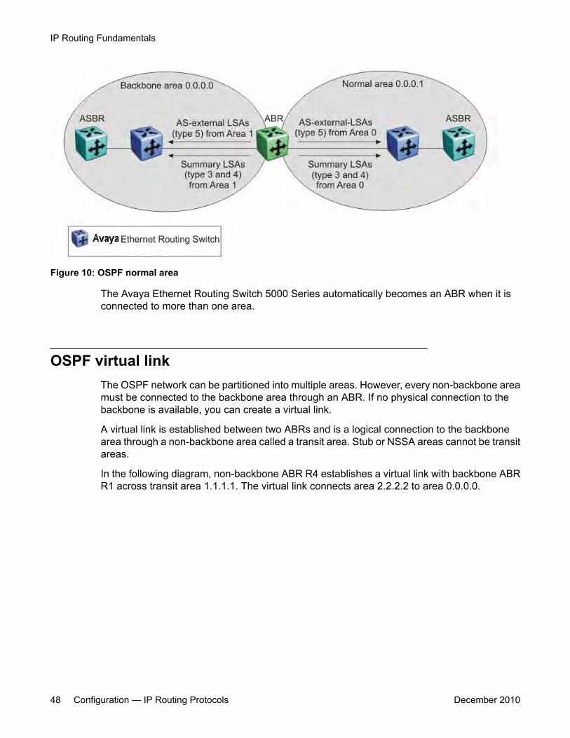
Figure 10: OSPF normal area
The Avaya Ethernet Routing Switch 5000 Series automatically becomes an ABR when it isconnected to more than one area.
OSPF virtual linkThe OSPF network can be partitioned into multiple areas. However, every non-backbone areamust be connected to the backbone area through an ABR. If no physical connection to thebackbone is available, you can create a virtual link.
A virtual link is established between two ABRs and is a logical connection to the backbonearea through a non-backbone area called a transit area. Stub or NSSA areas cannot be transitareas.
In the following diagram, non-backbone ABR R4 establishes a virtual link with backbone ABRR1 across transit area 1.1.1.1. The virtual link connects area 2.2.2.2 to area 0.0.0.0.
IP Routing Fundamentals
48 Configuration — IP Routing Protocols December 2010
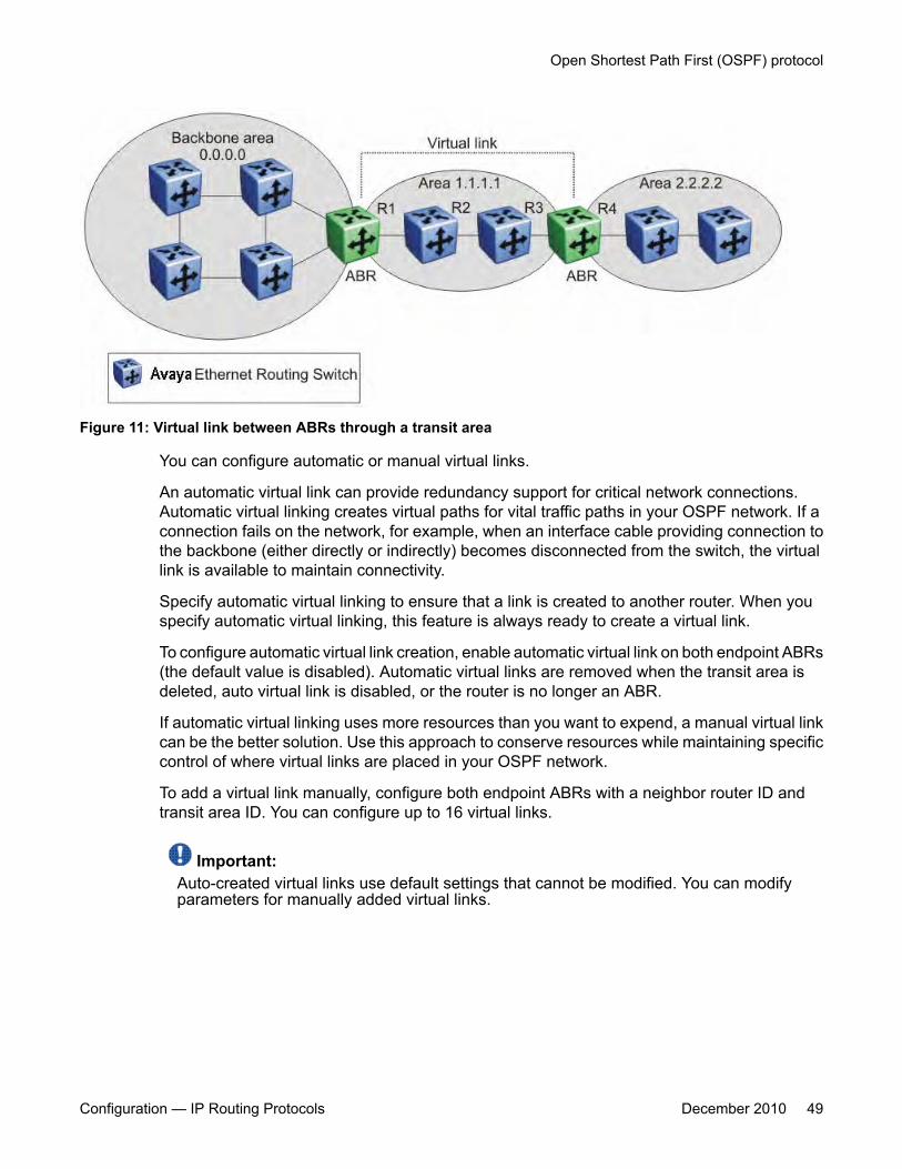
Figure 11: Virtual link between ABRs through a transit area
You can configure automatic or manual virtual links.
An automatic virtual link can provide redundancy support for critical network connections.Automatic virtual linking creates virtual paths for vital traffic paths in your OSPF network. If aconnection fails on the network, for example, when an interface cable providing connection tothe backbone (either directly or indirectly) becomes disconnected from the switch, the virtuallink is available to maintain connectivity.
Specify automatic virtual linking to ensure that a link is created to another router. When youspecify automatic virtual linking, this feature is always ready to create a virtual link.
To configure automatic virtual link creation, enable automatic virtual link on both endpoint ABRs(the default value is disabled). Automatic virtual links are removed when the transit area isdeleted, auto virtual link is disabled, or the router is no longer an ABR.
If automatic virtual linking uses more resources than you want to expend, a manual virtual linkcan be the better solution. Use this approach to conserve resources while maintaining specificcontrol of where virtual links are placed in your OSPF network.
To add a virtual link manually, configure both endpoint ABRs with a neighbor router ID andtransit area ID. You can configure up to 16 virtual links.
Important:Auto-created virtual links use default settings that cannot be modified. You can modifyparameters for manually added virtual links.
Open Shortest Path First (OSPF) protocol
Configuration — IP Routing Protocols December 2010 49
OSPF host routeAn OSPF router with hosts directly attached to its interfaces can use host routes to advertisethe attached hosts to its neighbors. You can configure up to 32 host routes.
Host routes are identified by the host IP address. You cannot configure the TOS for a hostroute as TOS-based routing is not supported. For each host directly connected to the router,configure the cost of the link to the host during host creation. You cannot modify this cost.
When a host is added to, or deleted from, a host route, the router updates the router LSAs andfloods them to neighbors in each area where that router has an interface.
The following is an example of parameters for a host route advertised in the LSA.
Host route in LSA
• Type: 3 (stub network)• LinkID: IP address of host directly connected to router• Link Data: 0xFFFFFFFF• Metric: configured cost of host
OSPF interfacesAn OSPF interface, or link, is configured on an IP interface. In the Ethernet Routing Switch5000, an IP interface can be either a brouter port or a VLAN. The state information associatedwith the interface is obtained from the underlying lower level protocols and the routing protocolitself.
Important:To change the interface type of an enabled OSPF interface, you must first disable it, changethe type, and then reenable it.
OSPF network types allow OSPF-neighboring between routers over various types of networkinfrastructures. You can configure each interface to support various network types. Thefollowing table describes the OSPF network interface types supported by the Ethernet RoutingSwitch 5000.
Related topics:Broadcast interfaces on page 51Passive interfaces on page 51
IP Routing Fundamentals
50 Configuration — IP Routing Protocols December 2010
Broadcast interfaces
Broadcast interfaces automatically discover every OSPF router on the network by sendingOSPF Hellos to the multicast group AllSPFRouters (224.0.0.5).
Neighboring is automatic and requires no configuration.
Broadcast interfaces support many attached routers and can address a single physicalmessage to all attached broadcast routers (sent to AllSPFRouters and AllDRouters).
Broadcast interfaces dynamically discover neighboring routers using the OSPF Hello Protocol.Each pair of routers on a broadcast network, such as Ethernet, communicate directly.
Passive interfaces
A passive interface is an interfacing network in OSPF that does not generate LSAs or formadjacencies. Passive interfaces are typically used on an access network.
Using passive interfaces limits the amount of CPU cycles required to perform the OSPF routingalgorithm.
Use a passive interface to enable an interface to advertise into an OSPF domain while limitingits adjacencies.
When you change the interface type to passive, the interfaceis advertised into the OSPFdomain as an internal stub network withthe following behaviors:
• does not send Hello packets to the OSPF domain
• does not receive Hello packets from the OSPF domain
• does not form adjacencies in the OSPF domain
The interface requires only that it be configured as passive to be advertised as an OSPFinternal route. If the interface is not a passive interface, to advertise a network into OSPF andnot form OSPF adjacencies, the interface must be configured as nonOSPF, and the localnetwork must be redistributed as an autonomous system external (ASE) LSA.
The network behind a passive interface is treated as a stub network and does not formadjacencies. The network is advertised into the OSPF area as an internal route.
OSPF packetsOSPF runs over IP, which means that an OSPF packet is sent with an IP data packet header.The protocol field in the IP header is 89, which identifies it as an OSPF packet.
Open Shortest Path First (OSPF) protocol
Configuration — IP Routing Protocols December 2010 51
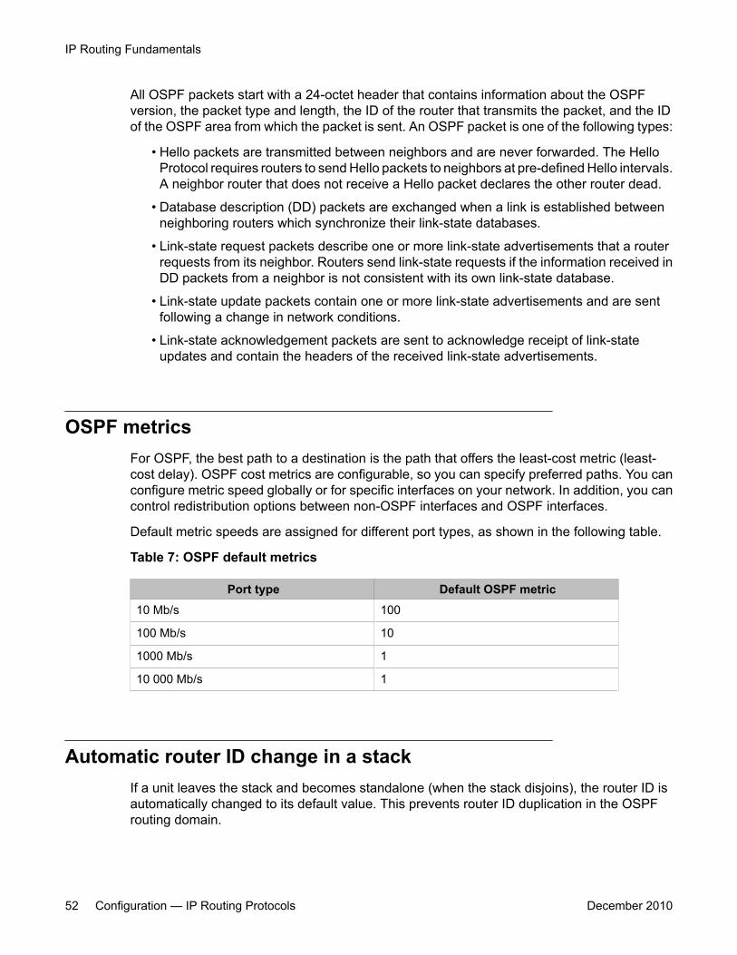
All OSPF packets start with a 24-octet header that contains information about the OSPFversion, the packet type and length, the ID of the router that transmits the packet, and the IDof the OSPF area from which the packet is sent. An OSPF packet is one of the following types:
• Hello packets are transmitted between neighbors and are never forwarded. The HelloProtocol requires routers to send Hello packets to neighbors at pre-defined Hello intervals.A neighbor router that does not receive a Hello packet declares the other router dead.
• Database description (DD) packets are exchanged when a link is established betweenneighboring routers which synchronize their link-state databases.
• Link-state request packets describe one or more link-state advertisements that a routerrequests from its neighbor. Routers send link-state requests if the information received inDD packets from a neighbor is not consistent with its own link-state database.
• Link-state update packets contain one or more link-state advertisements and are sentfollowing a change in network conditions.
• Link-state acknowledgement packets are sent to acknowledge receipt of link-stateupdates and contain the headers of the received link-state advertisements.
OSPF metricsFor OSPF, the best path to a destination is the path that offers the least-cost metric (least-cost delay). OSPF cost metrics are configurable, so you can specify preferred paths. You canconfigure metric speed globally or for specific interfaces on your network. In addition, you cancontrol redistribution options between non-OSPF interfaces and OSPF interfaces.
Default metric speeds are assigned for different port types, as shown in the following table.
Table 7: OSPF default metrics
Port type Default OSPF metric10 Mb/s 100
100 Mb/s 10
1000 Mb/s 1
10 000 Mb/s 1
Automatic router ID change in a stackIf a unit leaves the stack and becomes standalone (when the stack disjoins), the router ID isautomatically changed to its default value. This prevents router ID duplication in the OSPFrouting domain.
IP Routing Fundamentals
52 Configuration — IP Routing Protocols December 2010

To allow this feature to operate, IP blocking must be turned off (set to none) and OSPF mustbe globally enabled.
The new router ID value is temporary, that is, it is not saved in NVRAM. Therefore, upon reset,the old router ID is restored.
OSPF security mechanismsThe Ethernet Routing Switch 5000 implementation of OSPF includes security mechanisms toprevent unauthorized routers from attacking the OSPF routing domain. These securitymechanisms prevent a malicious person from joining an OSPF domain and advertising falseinformation in the OSPF LSAs. Likewise, security prevents a misconfigured router from joiningan OSPF domain. Currently there are two security mechanisms supported: simple passwordsecurity and Message Digest 5 (MD5) security.
Related topics:Simple Password on page 53Message Digest 5 on page 53
Simple Password
The Simple Password security mechanism is a simple-text password that is transmitted in theOSPF headers. Only routers that contain the same authentication ID in their LSA headers cancommunicate with each other.
Important:Avaya recommends that you not use this security mechanism because the password isstored in plain text and can be read from the configuration file or from the LSA packet.
Message Digest 5
Avaya recommends that you use Message Digest 5 (MD5) for OSPF security because itprovides standards-based (RFC 1321) authentication using 128-bit encryption. When you useMD5 for OSPF security, it is very difficult for a malicious user to compute or extrapolate thedecrypting codes from the OSPF packets.
When you use MD5, each OSPF packet has a message digest appended to it. The digest mustbe matched between sending and receiving routers. The message digest is calculated at boththe sending and receiving routers based on the MD5 key and any padding, and then compared.If the message digest computed at the sender and receiver does not match, the packet isrejected.
Open Shortest Path First (OSPF) protocol
Configuration — IP Routing Protocols December 2010 53

Each OSPF interface supports up to 2 keys, identifiable by key ID, to facilitate a smooth keytransition during the rollover process. Only the selected primary key is used to encrypt theOSPF transmit packets.
Equal Cost MultiPath (ECMP)The Equal Cost MultiPath (ECMP) feature allows routers to determine equal cost paths to thesame destination prefix. The multiple paths can be used for load sharing of traffic and allowsfaster convergence to other active paths in case of network failure. By maximizing load sharingamong equal-cost paths, links between routers can be used more efficiently when sending IPtraffic. The ECMP feature supports the following protocols:
• Open Shortest Path First (OSPF)
• Routing Information Protocol (RIP)
• Static Routes
ECMP is not supported on the Avaya Ethernet Routing Switch 5510. ECMP works in a mixedstack but cannot run on any Avaya Ethernet Routing Switch 5510 units in the stack.
Route policiesUsing standard routing schemes, a router forwards packets on routes that it has learnedthrough routing protocols such as RIP and OSPF or through the introduction of static routes.With route policies, the router can forward packets based on rule sets created by the networkadministrator. These rule sets, or policies, are then applied to the learned or static routes.
On the Avaya Ethernet Routing Switch 5000 Series , you can configure route policies for RIPand OSPF. When used in conjunction with these protocols, route policies can be used toperform the following tasks that are not possible using traditional routing methods:
• Listen for routing updates from specific gateways.• Listen for routing updates from specific networks.• Assign a specific subnet mask to be included with a network in the routing table.• Advertise routing updates from specific gateways.• Advertise routing updates to specific networks.• Assign a specific subnet mask to be included in the route summary packets.• Advertise routes learned by one protocol to another.
IP Routing Fundamentals
54 Configuration — IP Routing Protocols December 2010
The Ethernet Routing Switch 5000 Series supports the following types of policies:
• Accept (In) Policies
Accept polices are applied to incoming routing updates before they are applied to therouting table. In the case of RIP, accept policies can be applied to all incoming packets.Only one policy can be created for each RIP interface. In the case of OSPF, accept policiesare only applied to Type 5 External routes based on the advertising router ID. There canonly be one OSPF accept policy per switch and the policy is applied before updates areadded to the routing table from the link state database.
• Announce (Out) Policies
Announce policies are applied to outgoing routing updates before the routing updatepackets are actually transmitted from the switch. In the case of RIP, announce policiescan be applied to all outgoing packets. Only one policy can be created for each RIPinterface. Announce policies are not supported for OSPF as OSPF requires routinginformation to be consistent throughout the OSPF domain.
• Redistribution Policies
Redistribution policies are used to provide notification of addition or deletion of a route inthe routing table by one protocol to another protocol. OSPF redistribution policies sendredistributed routes as Type 5 External routes. To configure redistribution on a router, itmust be an ASBR. There can be only one OSPF redistribution route per switch andredistribution must be enabled. The OSPF accept policy takes precedence over theredistribution policy. You cannot configure a redistribution policy for RIP.
Route policies consist of the following items:
• Prefix Lists
- List of IP addresses with subnet masks.- Identified by a prefix list name and unique identifier.- Prefix lists support the comparison of ranges of incoming masks.
• Route Maps
- Contain a set of match and set parameters.- Match and set parameters can contain several prefix lists.- A set of match and set parameters are identified by a sequence number.- Accept and deny actions are associated with each sequenced parameter set.- Sequence numbers act as a preference setting. Sets with a lower sequence number
are preferred over those with a higher sequence number.To configure routing policies, create the appropriate prefix lists and then assign those prefixlists to route maps. Once all route maps have been created, assign them to the appropriatetype of policy.
Related topics:Route policies in a stack on page 56
Route policies
Configuration — IP Routing Protocols December 2010 55
Route policies in a stackIn a stacked environment, the following rules apply to routing policies:
• The policy database is stored in all stack units.
• Policy configuration is supported from only the base unit. The base unit sends updatesto non-base units to update the policy database in each stack unit.
• During database updates, only the database in the base unit is synchronized with thenon-base unit. The database in the non-base units are deleted during the exchange.
• Only the policies stored in the base unit are used by RIP and OSPF for policy application.
DHCP relayDynamic Host Configuration Protocol (DHCP) is a mechanism to assign network IP addresseson a dynamic basis to clients who request an address. DHCP is an extension of the Bootstrapprotocol (BootP). BootP/DHCP clients (workstations) generally use UDP broadcasts todetermine their IP addresses and configuration information. If such a host is on a VLAN thatdoes not include a DHCP server, the UDP broadcasts are by default not forwarded to serverslocated on different VLANs.
The Avaya Ethernet Routing Switch 5000 Series can resolve this issue using DHCP relay,which forwards the DHCP broadcasts to the IP address of the DHCP server. Network managersprefer to configure a small number of DHCP servers in a central location to lower administrativeoverhead. Routers must support DHCP relay so that hosts can access configurationinformation from servers several router hops away.
With DHCP relay enabled, the switch can relay client requests to DHCP servers on differentLayer 3 VLANs or in remote networks. It also relays server replies back to the clients.
To relay DHCP messages, two Layer 3 VLANs must be created: one connected to the clientand another providing a path to the DHCP server. DHCP relay can be enabled on a per-VLAN basis.
Important:The DHCP Relay feature shares resources with QoS. If the DHCP Relay feature is enabled,a QoS policy with a precedence of 11 cannot be installed.
For further information on QoS policies refer to Avaya Ethernet Routing Switch 5000 SeriesConfiguration - Quality of Service (NN47200-504).
The following figure shows a DHCP relay example, with an end station connected to subnet1, corresponding to VLAN 1. The Avaya Ethernet Routing Switch 5000 Series connects twosubnets by means of the virtual routing function. When the end station generates a DHCPrequest as a limited UDP broadcast to the IP address of all 1s (that is, 255.255.255.255), with
IP Routing Fundamentals
56 Configuration — IP Routing Protocols December 2010
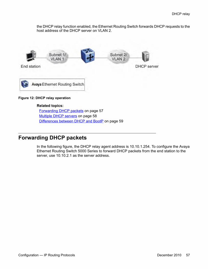
the DHCP relay function enabled, the Ethernet Routing Switch forwards DHCP requests to thehost address of the DHCP server on VLAN 2.
Figure 12: DHCP relay operation
Related topics:Forwarding DHCP packets on page 57Multiple DHCP servers on page 58Differences between DHCP and BootP on page 59
Forwarding DHCP packetsIn the following figure, the DHCP relay agent address is 10.10.1.254. To configure the AvayaEthernet Routing Switch 5000 Series to forward DHCP packets from the end station to theserver, use 10.10.2.1 as the server address.
DHCP relay
Configuration — IP Routing Protocols December 2010 57
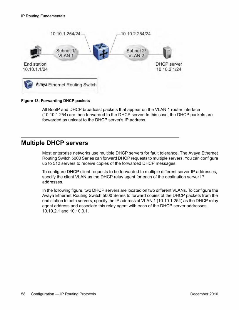
Figure 13: Forwarding DHCP packets
All BootP and DHCP broadcast packets that appear on the VLAN 1 router interface(10.10.1.254) are then forwarded to the DHCP server. In this case, the DHCP packets areforwarded as unicast to the DHCP server's IP address.
Multiple DHCP serversMost enterprise networks use multiple DHCP servers for fault tolerance. The Avaya EthernetRouting Switch 5000 Series can forward DHCP requests to multiple servers. You can configureup to 512 servers to receive copies of the forwarded DHCP messages.
To configure DHCP client requests to be forwarded to multiple different server IP addresses,specify the client VLAN as the DHCP relay agent for each of the destination server IPaddresses.
In the following figure, two DHCP servers are located on two different VLANs. To configure theAvaya Ethernet Routing Switch 5000 Series to forward copies of the DHCP packets from theend station to both servers, specify the IP address of VLAN 1 (10.10.1.254) as the DHCP relayagent address and associate this relay agent with each of the DHCP server addresses,10.10.2.1 and 10.10.3.1.
IP Routing Fundamentals
58 Configuration — IP Routing Protocols December 2010

Figure 14: Multiple BootP/DHCP servers
Differences between DHCP and BootPWith DHCP relay, the Avaya Ethernet Routing Switch 5000 Series supports the relay of DHCPand the Bootstrap protocol (BootP). The following differences between DHCP and BootP arespecified in RFC 2131:
• BootP enables the retrieval of an ASCII configuration file name and configuration serveraddress.
• A properly configured BootP server enables the switch to automatically learn its assignedIP address, subnet mask and the IP address of the default router (default gateway).
• DHCP defines mechanisms through which clients can be assigned a network address fora finite lease (allowing for reuse of IP addresses).
• DHCP provides the mechanism for clients to acquire all of the IP configuration parametersneeded to operate.
DHCP uses the BootP message format defined in RFC 951. The remainder of the options fieldconsists of a list of tagged parameters that are called options (RFC 2131).
DHCP relay
Configuration — IP Routing Protocols December 2010 59
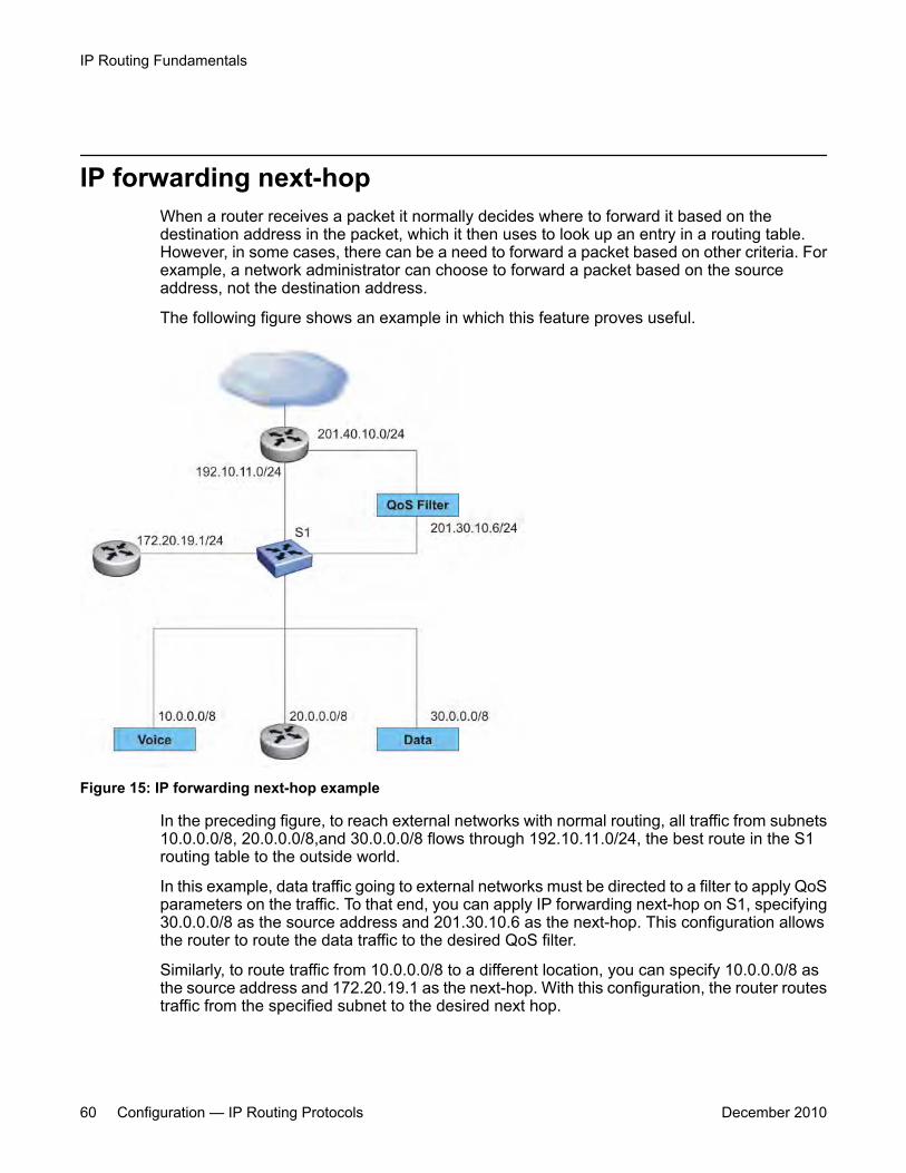
IP forwarding next-hopWhen a router receives a packet it normally decides where to forward it based on thedestination address in the packet, which it then uses to look up an entry in a routing table.However, in some cases, there can be a need to forward a packet based on other criteria. Forexample, a network administrator can choose to forward a packet based on the sourceaddress, not the destination address.
The following figure shows an example in which this feature proves useful.
Figure 15: IP forwarding next-hop example
In the preceding figure, to reach external networks with normal routing, all traffic from subnets10.0.0.0/8, 20.0.0.0/8,and 30.0.0.0/8 flows through 192.10.11.0/24, the best route in the S1routing table to the outside world.
In this example, data traffic going to external networks must be directed to a filter to apply QoSparameters on the traffic. To that end, you can apply IP forwarding next-hop on S1, specifying30.0.0.0/8 as the source address and 201.30.10.6 as the next-hop. This configuration allowsthe router to route the data traffic to the desired QoS filter.
Similarly, to route traffic from 10.0.0.0/8 to a different location, you can specify 10.0.0.0/8 asthe source address and 172.20.19.1 as the next-hop. With this configuration, the router routestraffic from the specified subnet to the desired next hop.
IP Routing Fundamentals
60 Configuration — IP Routing Protocols December 2010

Related topics:Limitations on page 61
LimitationsThe following are the limitations for IP Forwarding Next-hop:
• The IP Forwarding Next-hop feature is supported on the Ethernet Routing Switch 5600only.
• In a hybrid stack, you can use IP Forwarding Next-hop functionality only on the EthernetRouting Switch 5600 unit.
• Multipath is not supported.
UDP broadcast forwardingBy default, User Datagram Protocol (UDP) broadcast frames received on one VLAN are notrouted to another VLAN. However, some network applications, such as the NetBIOS nameservice, rely on UDP broadcasts to request a service or locate a server. To allow UDPbroadcasts to reach a remote server, the Ethernet Routing Switch supports UDP broadcastforwarding, which forwards the broadcasts to the server through a Layer 3 VLAN interface.
UDP broadcast forwarding is a general mechanism for selectively forwarding limited UDPbroadcasts received on an IP interface to a configured IP address. The packet is sent as aunicast packet to the server.
When a UDP broadcast is received on a router interface, it must meet the following criteriato be considered for forwarding:
• It must be a MAC-level broadcast.
• It must be an IP-limited broadcast.
• It must be for a configured UDP protocol.
• It must have a TTL value of at least 2.
For each ingress interface and protocol, the UDP broadcast packets are forwarded only to aunicast host address (the unicast IP address of the server for example).
When the UDP forwarding feature is enabled, a filter isinstalled that compares the UDPdestination port of all packets againstall the configured UDP forwarding entries. If a matchoccurs, thedestination IP of the incoming packet is checked for consistency withthe user-configured broadcast mask value for this source VLAN. Ifthese conditions are met, the TTLfield from the incoming packet isoverwritten with the user-configured TTL value, the destination
UDP broadcast forwarding
Configuration — IP Routing Protocols December 2010 61

IPof the packet is overwritten with the configured destination IP, andthe packet is routed to thedestination as a unicast frame.
Directed broadcastsWith the directed broadcasts feature enabled, the Ethernet Routing Switch can determine ifan incoming unicast frame is a directed broadcast for one of its interfaces. If so, the switchforwards the datagram onto the appropriate network using a link-layer broadcast.
With IP directed broadcasting enabled on a VLAN, the Ethernet Routing Switch forwards directbroadcast packets in two ways:
• through a connected VLAN subnet to another connected VLAN subnet
• through a remote VLAN subnet to the connected VLAN subnet
By default, this feature is disabled.
ARPThe Address Resolution Protocol (ARP) allows the Ethernet Routing Switch to dynamicallylearn Layer 2 Media Access Control (MAC) addresses, and to build a table with correspondingLayer 3 IP addresses.
Network stations using the IP protocol need both a physical (MAC) address and an IP addressto transmit a packet. If a network station knows only a network host's IP address, ARP enablesthe network station to determine a network host's physical address and bind the 32-bit IPaddress to a 48-bit MAC address. A network station can use ARP across a single network only,and the network hardware must support physical broadcasts.
If a network station wants to send a packet to a host but knows only the host's IP address, thenetwork station uses ARP to determine the host's physical address as follows:
1. The network station broadcasts a special packet, called an ARP request, that asksthe host at the specified IP address to respond with its physical address.
2. All network hosts receive the broadcast message.
3. Only the specified host responds with its hardware address.
4. The network station then maps the host's IP address to its physical address andsaves the results in an address resolution table for future use.
5. The network station's ARP table displays the association of the known MACaddresses to IP addresses.
IP Routing Fundamentals
62 Configuration — IP Routing Protocols December 2010
The lifetime for the learned MAC addresses is a configurable parameter. The switch executesARP lookups when this timer expires.
The default timeout value for ARP entries is 6 hours.
Static ARPIn addition to the dynamic ARP mechanism, the Ethernet Routing Switch supports a staticmechanism that allows for static ARP entries to be added. With Static ARP, you can manuallyassociate a device MAC address to an IP address. You can add and delete individual staticARP entries on the switch.
Static ARP entries can be used to solve the following instances encountered on manynetworks:
• To communicate with a device that does not respond to an ARP request.
• To prevent an existing ARP entry from aging out.
When a static ARP entry is configured, both the IP address and MAC address of a device isassigned to a physical port. This includes the VLAN number if the physical port is associatedwith a VLAN.
Proxy ARPProxy ARP allows the Ethernet Routing Switch to respond to an ARP request from a locallyattached host that is intended for a remote destination. It does so by sending an ARP responseback to the local host with the MAC address of the switch interface that is connected to thehost subnet. The reply is generated only if the switch has an active route to the destinationnetwork.
With Proxy ARP enabled, the connected host can reach remote subnets without the need toconfigure default gateways.
The following figure is an example of proxy ARP operation. In this example, host B wants tosend traffic to host C, so host B sends an ARP request for host C. However, the Avaya EthernetRouting Switch 5000 Series is between the two hosts, so the ARP message does not reachhost C. To enable communication between the two hosts, the Avaya Ethernet Routing Switch5000 Series intercepts the message, and responds to the ARP request with the IP address forhost C but with the MAC address of the switch itself. Host B then updates its ARP table withthe received information.
Static ARP
Configuration — IP Routing Protocols December 2010 63

Figure 16: Proxy ARP Operation
Avaya recommends Proxy ARP as a temporary fix only, for example, if you are graduallymoving hosts from one addressing scheme to another and you still want to maintainconnectivity between the disparately-addressed devices. You do not want Proxy ARP runningas a general rule because it causes hosts to generate ARP messages for every address thatthey want to reach on the Internet.
IP blocking for stacksIP Blocking is a Layer 3 feature of the Avaya Ethernet Routing Switch 5000 Series that providessafeguards for a stack where Layer 3 VLANs have port members across multiple stack units. IPBlocking is used whenever a unit leaves a stack or is rebooting inside the context of a stack.Depending on the setting in use, Layer 3 functionality is either continued or blocked by thisfeature.
You can set the IP Blocking mode on the base unit to either none or full.
When IP blocking is set to full, if any units leave the stack, those units run in Layer 2 mode.No Layer 3 settings remain on the units.
When IP blocking is set to none, if any units leave the stack, the Layer 3 configurations appliedto the stack are still applied on the individual units.
IP Routing Fundamentals
64 Configuration — IP Routing Protocols December 2010
In a stack environment of 2 units, Avaya recommends that you use IP blocking mode none. Inthis case, you can expect the following functional characteristics:
If either the stack base unit or nonbase unit becomes nonoperational, Layer 3 functionalitycontinues to run on the remaining unit.
A disadvantage of this configuration is that if the nonoperational unit does not rejoin the stack,address duplication occurs.
In stack environments of more than 2 units, Avaya recommends that you use IP blocking modefull. In this case, you can expect the following functional characteristics:
• If the stack base unit becomes nonoperational, the following occurs:
- The temporary base unit takes over base unit duties.
- The temporary base unit takes over responsibility to manage Layer 3 functionalityin the stack. When this occurs, the system updates the MAC addresses associatedwith each routing interface to be offset from the temporary base unit MAC address(rather than the base unit MAC address). During this period, some minor disruptionmay occur to routing traffic until end stations update their ARP cache with the newrouter MAC addresses. The Avaya Ethernet Routing Switch 5000 Series sends outgratuitous ARP messages on each routed VLAN for 5 minutes at 15 second intervalsto facilitate quick failover in this instance.
- If the nonoperational base unit does not rejoin the stack, no Layer 3 functionalityruns on the unit.
• If a stack nonbase unit becomes nonoperational, the following occurs:
- The stack continues to run normally with the base unit controlling Layer 3functionality.
- If the nonoperational nonbase unit does not rejoin the stack, no Layer 3 functionalityruns on the unit.
By default, the IP blocking mode is none (disabled).
Virtual Router Redundancy Protocol (VRRP)Because end stations are often configured with a static default gateway IP address, a loss ofthe default gateway router causes a loss of connectivity to the remote networks.
The Virtual Router Redundancy Protocol (VRRP) (RFC 2338) is designed to eliminate thesingle point of failure that can occur when the single static default gateway router for an endstation is lost. VRRP introduces the concept of a virtual IP address (transparent to users)shared between two or more routers connecting a common subnet to the enterprise network.With end hosts using the virtual IP address as the default gateway, VRRP provides dynamicdefault gateway redundancy in the event of failure.
Virtual Router Redundancy Protocol (VRRP)
Configuration — IP Routing Protocols December 2010 65
VRRP uses the following terms:
• VRRP router: a router running the VRRP protocol.• Virtual router: the abstract object managed by VRRP that is assigned the virtual IP
address and that acts as the default router for a set of IP addresses across a commonnetwork. Each virtual router is assigned a virtual router ID (VRID).
• Virtual router master: the VRRP router that assumes responsibility for forwarding packetssent to the IP address associated with the virtual router. The master router also respondsto packets sent to the virtual router IP address and answers ARP requests for this IPaddress.
• Virtual router backup: the router or routers that can serve as the failover router if themaster router becomes unavailable. If the master router fails, an election processprovides a dynamic transition of forwarding responsibility to a new master router.
• Priority: an 8-bit value assigned to all VRRP routers. A higher value represents a higherpriority for election to the master router. The priority can be a value from 1 to 255. If twoor more switches have the same priority value, the switch with the highest numerical IPaddress value is selected and becomes the VRRP master. When a master router fails,an election process takes place among the backup routers to dynamically reassign therole of the master router. The host is unaware of the entire process.
Related topics:VRRP operation on page 66VRRP topology example on page 67Critical IP address on page 69VRRP and SMLT on page 69VRRP fast advertisement interval on page 70
VRRP operationWhen you initialize a VRRP router, if there are no other VRRP routers enabled in the VLAN,then the initialized router assumes the role of the master router. When additional routers areenabled in the VLAN, an election process takes place among them to elect a master, basedon their priority.
The master router functions as the forwarding router for the IP address associated with thevirtual router. When a host sends traffic to a remote subnet, it sends an ARP request for theMAC address of the default gateway. In this case, the master router replies with the virtualMAC address. The benefit of using a virtual MAC address is that, if the master router fails, theVRRP backup router uses the same virtual MAC address. The virtual MAC address on theAvaya Ethernet Routing Switch 5000 Series is automatically set as:
00-00-5E-00-01-<VRID>where <VRID> is an integer value in the range 1 to 255 that represents the virtual routeridentification.
The master router responds to ARP requests for the IP address, forwards packets with adestination MAC address equal to the virtual router MAC address, and accepts only packets
IP Routing Fundamentals
66 Configuration — IP Routing Protocols December 2010

addressed to the IP address associated with the virtual router. The master router also sendsVRRP advertisements periodically (every 1 second by default) to all VRRP backup routers.
In the backup state, a VRRP router monitors the availability and state of the master router. Itdoes not respond to ARP requests and must discard packets with a MAC address equal to thevirtual router MAC address. It does not accept packets addressed to IP addresses associatedwith the virtual router. If a shutdown occurs, it transitions back to the initialize state.
If the master router fails, the backup router with the highest priority assumes the role of themaster router. It sends the VRRP advertisement and ARP request as described in thepreceding paragraphs and transitions to the controlling state. The virtual router IP address andMAC address does not change, thereby providing transparent operation
VRRP topology exampleThe following figure shows a VRRP topology example.
Virtual Router Redundancy Protocol (VRRP)
Configuration — IP Routing Protocols December 2010 67
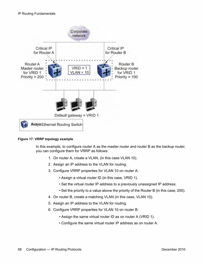
Figure 17: VRRP topology example
In this example, to configure router A as the master router and router B as the backup router,you can configure them for VRRP as follows:
1. On router A, create a VLAN, (in this case VLAN 10).
2. Assign an IP address to the VLAN for routing.
3. Configure VRRP properties for VLAN 10 on router A:
• Assign a virtual router ID (in this case, VRID 1).
• Set the virtual router IP address to a previously unassigned IP address.
• Set the priority to a value above the priority of the Router B (in this case, 200).
4. On router B, create a matching VLAN (in this case, VLAN 10).
5. Assign an IP address to the VLAN for routing.
6. Configure VRRP properties for VLAN 10 on router B:
• Assign the same virtual router ID as on router A (VRID 1).
• Configure the same virtual router IP address as on router A.
IP Routing Fundamentals
68 Configuration — IP Routing Protocols December 2010

• Set the priority to a value below that on Router A (in this case, 100).
When you enable VRRP on both of these switches, an election process takes place, andbecause router A has the higher priority, it is elected the master router. It then assumesresponsibility for the configured virtual router IP address.
Critical IP addressWithin a VRRP VLAN, it is possible for one link to go down, while the remaining links in theVLAN remain operational. Because the VRRP VLAN continues to function, a virtual routerassociated with that VLAN does not register a master router failure.
As a result, if the local router IP interface connecting the virtual router to the external networkfails, this does not automatically trigger a master router failover.
The critical IP address resolves this issue. If the critical IP address fails, it triggers a failover ofthe master router.
You can specify the local router IP interface uplink from the VRRP router to the network as thecritical IP address. This ensures that, if the local uplink interface fails, VRRP initiates a masterrouter failover to one of the backup routers.
In Figure 17: VRRP topology example on page 68, the local network uplink interface on router Ais shown as the critical IP address for router A. As well, the similar network uplink is shown asthe critical IP address for router B. Router B also requires a critical IP address for cases when itassumes the role of the master router.
VRRP and SMLTThe standard implementation of VRRP allows only one active master switch per IP subnet. Allother VRRP interfaces in a network are in backup mode.
However, a deficiency occurs when VRRP-enabled switches use Split Multi-Link Trunking(SMLT).
Normally, if a switch is connected to two SMLT aggregation switches, the end host traffic isload-shared on all uplinks to the aggregation switches (based on the MLT traffic distributionalgorithm). However, VRRP can only have one active routing interface enabled. All other VRRProuters are in backup mode. Therefore, if the SMLT aggregation switches run VRRP, all trafficthat reaches the backup VRRP router is forwarded over the Inter Switch Trunk (IST) linktowards the master VRRP router. In this case, the IST link might not have enough bandwidthto carry all the aggregated traffic.
Virtual Router Redundancy Protocol (VRRP)
Configuration — IP Routing Protocols December 2010 69
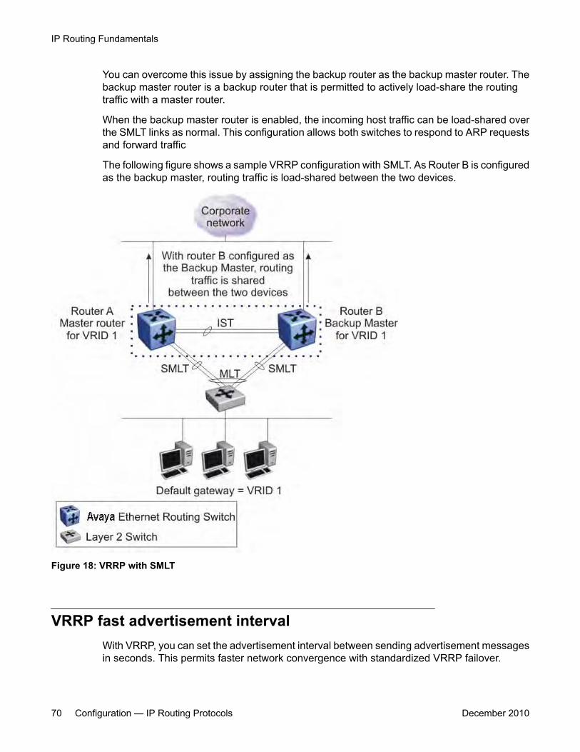
You can overcome this issue by assigning the backup router as the backup master router. Thebackup master router is a backup router that is permitted to actively load-share the routingtraffic with a master router.
When the backup master router is enabled, the incoming host traffic can be load-shared overthe SMLT links as normal. This configuration allows both switches to respond to ARP requestsand forward traffic
The following figure shows a sample VRRP configuration with SMLT. As Router B is configuredas the backup master, routing traffic is load-shared between the two devices.
Figure 18: VRRP with SMLT
VRRP fast advertisement intervalWith VRRP, you can set the advertisement interval between sending advertisement messagesin seconds. This permits faster network convergence with standardized VRRP failover.
IP Routing Fundamentals
70 Configuration — IP Routing Protocols December 2010
However, losing connections to servers for more than a second can result in missing criticalfailures. Customer network uptime in many cases requires faster network convergence, whichmeans network problems must be detected within hundreds of milliseconds.
To meet these requirements, Avaya Ethernet Routing Switch 5000 Series supports a fastadvertisement interval parameter. The fast advertisement interval is similar to theadvertisement interval except for the unit of measure and range. The fast advertisementinterval is expressed in milliseconds and the range is from 200 to 1000 milliseconds. To usethe fast advertisement interval, you must configure a value for the parameter and explicitlyenable the feature.
When the fast advertisement interval is enabled, VRRP can only communicate with otherEthernet Routing Switch devices with the same settings.
Virtual Router Redundancy Protocol (VRRP)
Configuration — IP Routing Protocols December 2010 71

IP Routing Fundamentals
72 Configuration — IP Routing Protocols December 2010
Chapter 4: IP multicast fundamentals
To manage multicast traffic, the Ethernet Routing Switch 5000 Series supports PIM-SM (for IGMPv1 andIGMPv2) and IGMP snooping (for IGMPv1, IGMPv2, and IGMPv3). You can enable IGMP snooping on aper-VLAN basis either on a Layer 2 or a Layer 3 VLAN. You can enable PIM-SM on Layer 3 VLANs only.
This chapter describes the fundamentals of IP multicast as they apply to the Ethernet Routing Switch 5000Series.
Navigation• Overview of IP multicast on page 73
• Internet Group Management Protocol on page 80
• IGMP snooping on page 88
• IGMP Send Query on page 98
• Protocol Independent Multicast-Sparse Mode on page 98
• PIM passive interfaces on page 108
• PIM-SSM
• PIM-SM capabilities and limitations on page 109
• Enabling or disabling routing with IGMP enabled on page 110
• Nonsupported IGMP features on page 111
• Default PIM-SM values on page 111
Overview of IP multicastMost traditional network applications such as Web browsers and e-mail employ unicastconnections in which each client sets up a separate connection to a server to access specificdata. However, with certain applications such as audio and video streaming, more than oneclient accesses the same data at the same time. With these applications, if the server sendsthe same data to each individual client using unicast connections, the multiple connectionswaste both server and network capacity. For example, if a server offers a 1Mbit/sec live video
Configuration — IP Routing Protocols December 2010 73

stream for each client, a 100Mbit/sec NIC card on the server can be completely saturated after90 client connections. The following figure shows an example of this waste of resources.
Figure 19: Wasteful propagation of multiple copies of the same unicast stream
Multicasting provides the ability to transmit only one stream of data to all the interested clients atthe same time. The following figure shows a simple example of how multicasting works. Thesource of the multicast data forwards only one stream to the nearest downstream router, andeach subsequent downstream router forwards a copy of the same data stream to the recipientswho are registered to receive it.
IP multicast fundamentals
74 Configuration — IP Routing Protocols December 2010
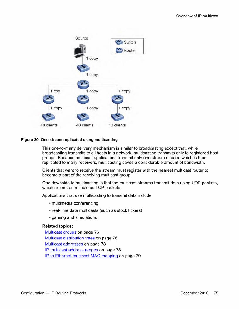
Figure 20: One stream replicated using multicasting
This one-to-many delivery mechanism is similar to broadcasting except that, whilebroadcasting transmits to all hosts in a network, multicasting transmits only to registered hostgroups. Because multicast applications transmit only one stream of data, which is thenreplicated to many receivers, multicasting saves a considerable amount of bandwidth.
Clients that want to receive the stream must register with the nearest multicast router tobecome a part of the receiving multicast group.
One downside to multicasting is that the multicast streams transmit data using UDP packets,which are not as reliable as TCP packets.
Applications that use multicasting to transmit data include:
• multimedia conferencing• real-time data multicasts (such as stock tickers)• gaming and simulations
Related topics:Multicast groups on page 76Multicast distribution trees on page 76Multicast addresses on page 78IP multicast address ranges on page 78IP to Ethernet multicast MAC mapping on page 79
Overview of IP multicast
Configuration — IP Routing Protocols December 2010 75
Multicast groupsTo receive a multicast stream from a particular source, hosts must register with the nearestmulticast router. The router adds all interested hosts to a multicast group, which is identifiedby a multicast IP address.
Multicast routers use Internet Group Membership Protocol (IGMP) to learn the existence ofhost group members on their directly attached subnets. To identify the hosts that want to beadded to a group, a querier router sends out IGMP queries to each local network. A host thatwants to belong to the group sends a response in the form of an IGMP membership report.
Each multicast router maintains a multicast routing table that lists each source, group (S,G)pair, which identifies the IP address of the source and the multicast address of the receivinggroup. For each (S,G) pair, the router maintains a list of downstream forwarding ports to whichthe multicast traffic is forwarded and the upstream port where the multicast traffic is received.
Multicast distribution treesA multicast distribution tree consists of the routers that forward multicast data from a particularsource to all registered multicast group members. When all routers in the multicast networkhave determined their upstream and downstream interfaces for a particular group, the multicasttree is formed. At the root of the tree is the source of the multicast stream, and the branchesare the destination routers that want to receive the multicast stream. Different multicastprotocols use different techniques to discover delivery paths.
The following figure is an example of a simple distribution tree, where the arrows indicate themulticast delivery path from the source to the group members along the multicast distributiontree.
IP multicast fundamentals
76 Configuration — IP Routing Protocols December 2010

Figure 21: Multicast distribution tree
Related topics:Reverse Path Forwarding on page 77
Reverse Path Forwarding
Reverse Path Forwarding is the means by which multicast routers ensure a loop-free topology.When a multicast packet arrives on an interface, the router compares the source address ofthe packet against the unicast routing table to determine whether the receiving interface is onthe shortest path back to the source. If the receiving interface is the one the router would use toforward a unicast packet back to the source, the reverse path check passes, and the routerforwards the multicast packet to its downstream neighbors. If the packet does not arrive on anupstream interface, the router discards the packet.
For example, in the preceding figure, if router E receives a packet from source S through routerB, which is not on the optimal path back to the source, router E discards the packet. However, ifrouter E receives the source packet from router D, which according to the unicast routing tableis the next hop toward the source, router E forwards the incoming packet downstream to routerG.
Without reverse path forwarding, loops can form in the network. For example, Router E canforward all packets coming from router D to router B, and router B can in turn forward the sametraffic to router D, thereby causing a loop. With the RPF checks running on these routers, noloop can form.
Overview of IP multicast
Configuration — IP Routing Protocols December 2010 77
Multicast addressesEach multicast host group is assigned a unique multicast address. To reach all members ofthe group, a sender uses the multicast address as the destination address of the datagram.
An IP version 4 multicast address is a Class D address (the high-order bits are set to 1110)from 224.0.1.0 to 239.255.255.255. These addresses are assigned statically for use bypermanent groups and dynamically for use by transient groups.
The multicast address range 224.0.0.0/24, 224.128.0.0/24, 225.0.0.0/24, 225.128.0.0/24 upto 239.0.0.0/24, 239.128.0.0/24 maps to reserved multicast MAC addresses. You cannot usethese addresses for multicast data traffic.
IP multicast address rangesIP multicast utilizes D class addresses, which range from 224.0.0.0 to 239.255.255.255.Although subnet masks are commonly used to configure IP multicast address ranges, theconcept of subnets does not exist for multicast group addresses. Consequently, the usualunicast conventions where you reserve the all 0s subnets, all 1s subnets, all 0s host addresses,and all 1s host addresses do not apply when dealing with the IP multicast range of addresses.
Addresses from 224.0.0.0 through 224.0.0.255 are reserved by the Internet Assigned NumbersAuthority (IANA) for link-local network applications. Packets with an address in this range arenot forwarded by multicast capable routers by design. For example, Open Shortest Path First(OSPF) uses both 224.0.0.5 and 224.0.0.6 and Virtual Router Redundancy Protocol (VRRP)uses 224.0.0.18 to communicate across a local broadcast network segment.
IANA has also reserved the range of 224.0.1.0 through 224.0.1.255 for well-knownapplications. These addresses are also assigned by IANA to specific network applications. Forexample, the Network Time Protocol (NTP) uses 224.0.1.1 and Mtrace uses 224.0.1.32. RFC1700 contains a complete list of these reserved numbers.
Multicast addresses in the 232.0.0.0/8 (232.0.0.0 to 232.255.255.255) range are reserved onlyfor source-specific multicast (SSM) applications, such as one-to-many applications. (For moreinformation, see RFC 4607). While this range is the publicly reserved range for SSMapplications, private networks can use other address ranges for SSM.
Finally, addresses in the range 239.0.0.0/8 (239.0.0.0 to 239.255.255.255) are administrativelyscoped addresses, meaning they are reserved for use in private domains and cannot beadvertised outside that domain. This multicast range is analogous to the 10.0.0.0/8,172.16.0.0/20, and 192.168.0.0/16 private address ranges in the unicast IP space.
Technically, a private network can only assign multicast addresses from 224.0.2.0 through238.255.255.255 to applications that are publicly accessible on the Internet. Multicast
IP multicast fundamentals
78 Configuration — IP Routing Protocols December 2010
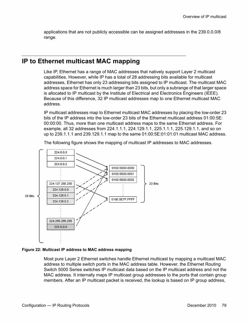
applications that are not publicly accessible can be assigned addresses in the 239.0.0.0/8range.
IP to Ethernet multicast MAC mappingLike IP, Ethernet has a range of MAC addresses that natively support Layer 2 multicastcapabilities. However, while IP has a total of 28 addressing bits available for multicastaddresses, Ethernet has only 23 addressing bits assigned to IP multicast. The multicast MACaddress space for Ethernet is much larger than 23 bits, but only a subrange of that larger spaceis allocated to IP multicast by the Institute of Electrical and Electronics Engineers (IEEE).Because of this difference, 32 IP multicast addresses map to one Ethernet multicast MACaddress.
IP multicast addresses map to Ethernet multicast MAC addresses by placing the low-order 23bits of the IP address into the low-order 23 bits of the Ethernet multicast address 01:00:5E:00:00:00. Thus, more than one multicast address maps to the same Ethernet address. Forexample, all 32 addresses from 224.1.1.1, 224.129.1.1, 225.1.1.1, 225.129.1.1, and so onup to 239.1.1.1 and 239.129.1.1 map to the same 01:00:5E:01:01:01 multicast MAC address.
The following figure shows the mapping of multicast IP addresses to MAC addresses.
Figure 22: Multicast IP address to MAC address mapping
Most pure Layer 2 Ethernet switches handle Ethernet multicast by mapping a multicast MACaddress to multiple switch ports in the MAC address table. However, the Ethernet RoutingSwitch 5000 Series switches IP multicast data based on the IP multicast address and not theMAC address. It internally maps IP multicast group addresses to the ports that contain groupmembers. After an IP multicast packet is received, the lookup is based on IP group address,
Overview of IP multicast
Configuration — IP Routing Protocols December 2010 79
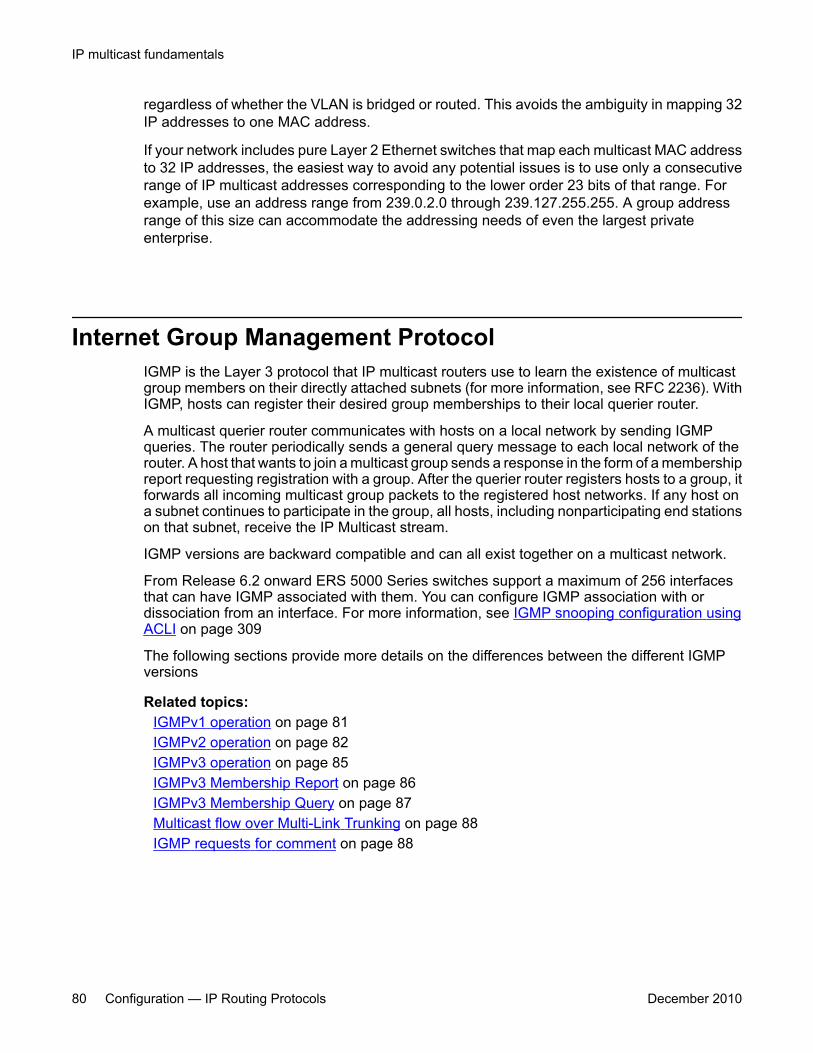
regardless of whether the VLAN is bridged or routed. This avoids the ambiguity in mapping 32IP addresses to one MAC address.
If your network includes pure Layer 2 Ethernet switches that map each multicast MAC addressto 32 IP addresses, the easiest way to avoid any potential issues is to use only a consecutiverange of IP multicast addresses corresponding to the lower order 23 bits of that range. Forexample, use an address range from 239.0.2.0 through 239.127.255.255. A group addressrange of this size can accommodate the addressing needs of even the largest privateenterprise.
Internet Group Management ProtocolIGMP is the Layer 3 protocol that IP multicast routers use to learn the existence of multicastgroup members on their directly attached subnets (for more information, see RFC 2236). WithIGMP, hosts can register their desired group memberships to their local querier router.
A multicast querier router communicates with hosts on a local network by sending IGMPqueries. The router periodically sends a general query message to each local network of therouter. A host that wants to join a multicast group sends a response in the form of a membershipreport requesting registration with a group. After the querier router registers hosts to a group, itforwards all incoming multicast group packets to the registered host networks. If any host ona subnet continues to participate in the group, all hosts, including nonparticipating end stationson that subnet, receive the IP Multicast stream.
IGMP versions are backward compatible and can all exist together on a multicast network.
From Release 6.2 onward ERS 5000 Series switches support a maximum of 256 interfacesthat can have IGMP associated with them. You can configure IGMP association with ordissociation from an interface. For more information, see IGMP snooping configuration usingACLI on page 309
The following sections provide more details on the differences between the different IGMPversions
Related topics:IGMPv1 operation on page 81IGMPv2 operation on page 82IGMPv3 operation on page 85IGMPv3 Membership Report on page 86IGMPv3 Membership Query on page 87Multicast flow over Multi-Link Trunking on page 88IGMP requests for comment on page 88
IP multicast fundamentals
80 Configuration — IP Routing Protocols December 2010

IGMPv1 operationIGMP version 1 is the simplest of the three IGMP versions and widely deployed.
IGMPv1 supports two different message types:
• 0x11—Membership Query message. Packets are sent to the all-systems multicast group(224.0.0.1).
• 0x12—Membership Report message. Packets are sent to the group that the host intendsto join.
The IGMPv1 router periodically sends host membership queries (also known as generalqueries) to its attached local subnets to inquire if any hosts are interested in joining anymulticast groups. The interval between queries is a configurable value on the router. A hostthat wants to join a multicast group sends a membership report message to the nearest router,one report for each joined multicast group. After receiving the report, the router adds theMulticast IP address and the host port to its forwarding table. The router then forwards anymulticast traffic for that multicast IP address to the member ports.
The router keeps a list of multicast group memberships for each attached network, and a GroupMembership Interval timer for each membership. Repeated IGMP membership reports refreshthe timer. If no reports are received before the timer expires, the router sends a query message.
In some cases, the host does not wait for a query to send report messages to the router. Uponinitialization, the host can immediately issue a report for each of the multicast groups that itsupports. The router accepts and processes these asynchronous reports the same way itaccepts requested reports.
Related topics:IGMPv1 leave process on page 81Host report suppression on page 82
IGMPv1 leave process
After hosts and routers are in a steady state, they communicate in a way that minimizes theexchange of queries and reports. The designated routers set up a path between the IPMulticast stream source and the end stations and periodically query the end stations todetermine whether they want to continue participation. If any host on the subnet continues toparticipate, all hosts, including nonparticipating end stations on the subnet, receive the IPMulticast stream.
If all hosts on the subnet leave the group, the router continues to send general queries to thesubnet. If no hosts send reports after three consecutive queries, the router determines that nogroup members are left on the subnet.
Internet Group Management Protocol
Configuration — IP Routing Protocols December 2010 81

Host report suppression
A host that receives a query delays its reply by a random interval and listens for a reply fromanother host in the same host group. Consider a network that includes two host members—host A and host B—of the same multicast group. The router sends out a host membershipquery on the local network. Both host A and host B receive the query and listen on the networkfor a host membership report. The delay timer for host B expires first, so host B responds tothe query with a membership report. Hearing the response, host A does not send a report ofits own for the same group.
Figure 23: IGMP report suppression
IGMPv2 operationIGMPv2 extends the IGMPv1 features by implementing a host leave message to quickly reportgroup membership termination to the routing protocol. Instead of routers sending multiplequeries before determining that hosts have left a group, the hosts can send a leave message.This feature is important for multicast groups with highly volatile group membership.
The IGMPv2 join process is similar to IGMPv1.
IGMPv2 also implements a querier election process.
IGMPv2 adds support for three new message types:
• 0x11—General Query and Group Specific Query message• 0x16—Version 2 Membership Report (sent to the destination IP address of the group
being reported)• 0x17—Version 2 Membership Leave message (sent to all-router multicast address:
224.0.0.2)IGMPv2 also supports IGMPv1 messages.
IP multicast fundamentals
82 Configuration — IP Routing Protocols December 2010
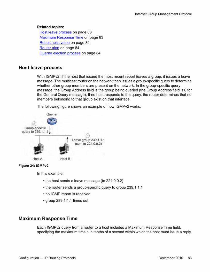
Related topics:Host leave process on page 83Maximum Response Time on page 83Robustness value on page 84Router alert on page 84Querier election process on page 84
Host leave process
With IGMPv2, if the host that issued the most recent report leaves a group, it issues a leavemessage. The multicast router on the network then issues a group-specific query to determinewhether other group members are present on the network. In the group-specific querymessage, the Group Address field is the group being queried (the Group Address field is 0 forthe General Query message). If no host responds to the query, the router determines that nomembers belonging to that group exist on that interface.
The following figure shows an example of how IGMPv2 works.
Figure 24: IGMPv2
In this example:
• the host sends a leave message (to 224.0.0.2)
• the router sends a group-specific query to group 239.1.1.1
• no IGMP report is received
• group 239.1.1.1 times out
Maximum Response Time
Each IGMPv2 query from a router to a host includes a Maximum Response Time field,specifying the maximum time n in tenths of a second within which the host must issue a reply.
Internet Group Management Protocol
Configuration — IP Routing Protocols December 2010 83

The host uses this value to calculate a random value between 0 and n tenths of a second forthe period that it waits before sending a response.
IGMPv1 queries do not specify a maximum response time. Instead, the maximum responsetime is a fixed value of 100, that is, 10 seconds.
Robustness value
As part of IGMP configuration, the robustness value lets you configure the switch to offsetexpected packet loss on a subnet. If you expect a network to lose IGMP query or membershipreport packets, you can increase the robustness value to offset the lost packets.
When the Ethernet Routing Switch receives an IGMP report from a host, the switch refreshesthe expiration time for the group member. The timeout for a group member is a function of thequery interval, robustness value, and the maximum response time. If the robustness value isincreased, the group member lifetime increases as well, according to the following formula:
IGMP group member lifetime = (IGMP query interval * robustness value) + maximum responsetime.
If the network is congested, the switch is more likely to miss an IGMP report from a host, orthe host can miss the query from the router. To offset the network loss, you can increase therobustness value to extend the life time for the group members.
Router alert
The router alert feature instructs the router to drop control packets that do not have the router-alert flag in the IP header. You can use this option to optimize the performance of multicastrouters. When you enable router alert, a router needs to examine only the packets that havethe router-alert option flagged, and can ignore all other multicast control packets destined toit. This optimizes the performance in packet processing. This feature is especially useful inrouters-only networks. (It is difficult to force a host to send packets with the router-alert option.)
Querier election process
There is normally only one querier per subnet. When multiple IGMPv2 routers are present on anetwork, the router with the lowest IP address is elected to send queries. All multicast routersstart up as a querier on each attached network. If a multicast router hears a query messagefrom a router with a lower IP address, it becomes a nonquerier on that network.
IP multicast fundamentals
84 Configuration — IP Routing Protocols December 2010

IGMPv3 operationIGMPv3 adds support for source filtering. The IGMPv3 host can report its interest in receivingmulticast packets from only specific source addresses, or the host can report its interest inreceiving multicast packets from all but specific source addresses.
IGMPv3 is mostly used in voice and video conferences where multiple people can be part ofthe same conference. The IGMPv3 packet format adds a v3 Report message type (0x22) andalso includes Source-and-Group-specific Query messages.
The message type for Source-and-Group-specific Query message is 0x11, the same asIGMPv1 and IGMPv2. The different Query message versions are identified as follows:
• If the size of the IGMP message type is 8, then it is a v1 or v2 Query message.
• If the Group Address field is 0, then it is a General Query.
• If the Group Address field is a valid multicast IP address, then it is a Group-specific Query.
• If the Group Address field is a valid address and the Number of Sources field is nonzero,then it is a Group-and-Source specific Query message.
Each IGMPv3 Report contains a list of group records. The Group Record contains the multicastgroup address and the list of source addresses. The record type field specifies whether toINCLUDE or EXCLUDE the list of source addresses that are provided in the Source Addressfield. For example, to include packets from source 10.10.10.1, the report contains anINCLUDE(10.10.10.1) record.
The list of source addresses can be empty, which is represented by braces ({}), which meanseither to INCLUDE or EXCLUDE none. For example, the host that wants to receive packetsfrom all group members can send a report with an EXCLUDE({}) record and a host that wants toleave a group can send a report with an INCLUDE({}) record, which is similar to a leavemessage.
In the following figure, hosts A, B, C, D, E, and F are part of a conference group G1. All hostsexcept F send a report for group G1 with the mode as INCLUDE(A, B, C, D, E, F) containingall the source addresses. Host F, which is not interested in listening to C and D, sends a report togroup G1 with the mode as EXCLUDE(C, D).
Internet Group Management Protocol
Configuration — IP Routing Protocols December 2010 85
Figure 25: IGMPv3
The router adds the multicast IP address and the list of sources in the forwarding table. Therouter forwards the packets from A, B, E, and F to all ports. If the packets are received from Cand D, it is forwarded to all ports except port 11.
IGMPv3 Membership ReportIGMPv3 provides the capability to learn which sources are of interest to specific systems, forpackets sent to any particular multicast address. IGMPv3 Membership Reports are sent by IPsystems to report the current multicast reception state, or changes in the multicast receptionstate. Included in a Report message, there are a number of different types of Group Records.The following table shows how IGMPv3 handles the various record types.
IGMPv3 record type DefinitionMODE_IS_INCLUDE (1) Indicates that the system has a filter mode of
INCLUDE for the specified multicastaddress. The Source Address fields in thisGroup Record contain the system’s sourcelist for the specified multicast address, if it isnon-empty.
MODE_IS_EXCLUDE (2) Indicates that the system has a filter mode ofEXCLUDE for the specified multicastaddress. The Source Address fields in thisGroup Record contain the system’s sourcelist for the specified multicast address, if it isnon-empty.
CHANGE_TO_INCLUDE_MODE (3) Indicates that the system has changed toINCLUDE filter mode for the specifiedmulticast address. The Source Address
IP multicast fundamentals
86 Configuration — IP Routing Protocols December 2010
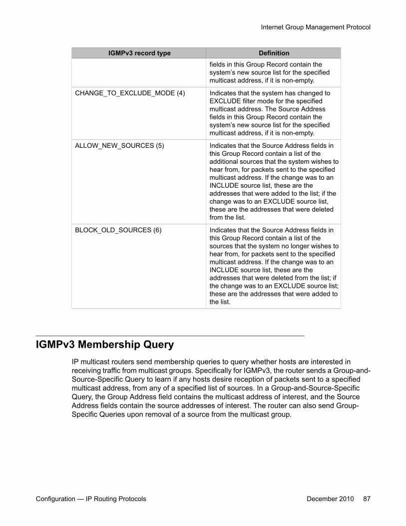
IGMPv3 record type Definitionfields in this Group Record contain thesystem’s new source list for the specifiedmulticast address, if it is non-empty.
CHANGE_TO_EXCLUDE_MODE (4) Indicates that the system has changed toEXCLUDE filter mode for the specifiedmulticast address. The Source Addressfields in this Group Record contain thesystem’s new source list for the specifiedmulticast address, if it is non-empty.
ALLOW_NEW_SOURCES (5) Indicates that the Source Address fields inthis Group Record contain a list of theadditional sources that the system wishes tohear from, for packets sent to the specifiedmulticast address. If the change was to anINCLUDE source list, these are theaddresses that were added to the list; if thechange was to an EXCLUDE source list,these are the addresses that were deletedfrom the list.
BLOCK_OLD_SOURCES (6) Indicates that the Source Address fields inthis Group Record contain a list of thesources that the system no longer wishes tohear from, for packets sent to the specifiedmulticast address. If the change was to anINCLUDE source list, these are theaddresses that were deleted from the list; ifthe change was to an EXCLUDE source list;these are the addresses that were added tothe list.
IGMPv3 Membership QueryIP multicast routers send membership queries to query whether hosts are interested inreceiving traffic from multicast groups. Specifically for IGMPv3, the router sends a Group-and-Source-Specific Query to learn if any hosts desire reception of packets sent to a specifiedmulticast address, from any of a specified list of sources. In a Group-and-Source-SpecificQuery, the Group Address field contains the multicast address of interest, and the SourceAddress fields contain the source addresses of interest. The router can also send Group-Specific Queries upon removal of a source from the multicast group.
Internet Group Management Protocol
Configuration — IP Routing Protocols December 2010 87
Multicast flow over Multi-Link TrunkingIn the current release, the Ethernet Routing Switch 5000 Series supports multicast traffic andcontrol packets only on the base link of the MLT.
IGMP requests for commentFor more information on IGMP, see the following requests for comment (RFC):
• For IGMPv1, see RFC 1112.
• For IGMPv2, see RFC 2236.
• For IGMPv3, see RFC 3376.
• For IGMP snooping, see RFC 4541.
• For IGMP management information bases (MIB), see RFC 2933
IGMP snoopingIf at least one host on a VLAN specifies that it is a member of a group, by default, the EthernetRouting Switch 5000 Series forwards to that VLAN all datagrams bearing the multicast addressof that group. All ports on the VLAN receive the traffic for that group.
The following figure shows an example of this scenario. In this example, the IGMP sourceprovides an IP Multicast stream to a designated router. Because the local network containsreceivers, the designated router forwards the IP Multicast stream to the network. Switcheswithout IGMP snoop enabled flood the IP Multicast traffic to all segments on the local subnet.The receivers requesting the traffic receive the desired stream, but so do all other hosts on thenetwork. Although the nonparticipating end stations can filter the IP Multicast traffic, the IPMulticast traffic still exists on the subnet and consumes bandwidth.
IP multicast fundamentals
88 Configuration — IP Routing Protocols December 2010
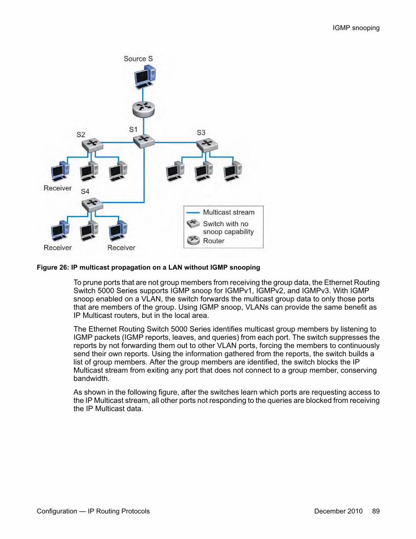
Figure 26: IP multicast propagation on a LAN without IGMP snooping
To prune ports that are not group members from receiving the group data, the Ethernet RoutingSwitch 5000 Series supports IGMP snoop for IGMPv1, IGMPv2, and IGMPv3. With IGMPsnoop enabled on a VLAN, the switch forwards the multicast group data to only those portsthat are members of the group. Using IGMP snoop, VLANs can provide the same benefit asIP Multicast routers, but in the local area.
The Ethernet Routing Switch 5000 Series identifies multicast group members by listening toIGMP packets (IGMP reports, leaves, and queries) from each port. The switch suppresses thereports by not forwarding them out to other VLAN ports, forcing the members to continuouslysend their own reports. Using the information gathered from the reports, the switch builds alist of group members. After the group members are identified, the switch blocks the IPMulticast stream from exiting any port that does not connect to a group member, conservingbandwidth.
As shown in the following figure, after the switches learn which ports are requesting access tothe IP Multicast stream, all other ports not responding to the queries are blocked from receivingthe IP Multicast data.
IGMP snooping
Configuration — IP Routing Protocols December 2010 89
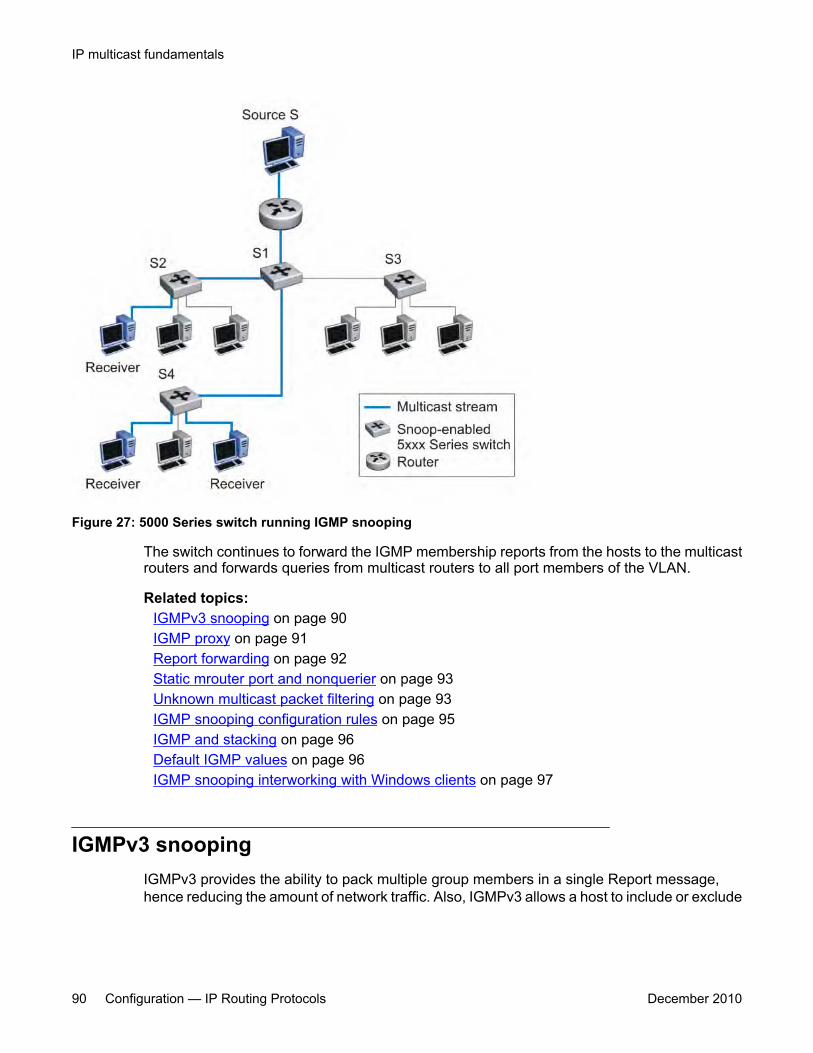
Figure 27: 5000 Series switch running IGMP snooping
The switch continues to forward the IGMP membership reports from the hosts to the multicastrouters and forwards queries from multicast routers to all port members of the VLAN.
Related topics:IGMPv3 snooping on page 90IGMP proxy on page 91Report forwarding on page 92Static mrouter port and nonquerier on page 93Unknown multicast packet filtering on page 93IGMP snooping configuration rules on page 95IGMP and stacking on page 96Default IGMP values on page 96IGMP snooping interworking with Windows clients on page 97
IGMPv3 snoopingIGMPv3 provides the ability to pack multiple group members in a single Report message,hence reducing the amount of network traffic. Also, IGMPv3 allows a host to include or exclude
IP multicast fundamentals
90 Configuration — IP Routing Protocols December 2010
a list of source addresses for each multicast group of which the host is a member. Routersmerge the source address requirements of different hosts for each group.
The Ethernet Routing Switch 5000 Series switch supports IGMPv3 source filtering capabilitywith IGMPv3 Snooping. IGMPv3 Snooping remains backward compatible with IGMPv1 andIGMPv2.
IGMPv3 Snooping operates independently of PIM-SSM.
On the Ethernet Routing Switch 5000 Series, IGMPv3 Snooping-enabled interfaces processIGMP reports as follows:
• process IGMPv3 reports independent of PIM-SSM
• process all six IGMPv3 group record types
• process all IGMPv3 source information
• backward compatible with IGMPv1/IGMPv2 reports
Due to limitations on the ERS 5510 switch, IGMPv3 source filtering is not implemented inhardware and multicast traffic entering the system through an ERS 5510 is not filtered basedon source. The ERS 5510 switch is only able to add the multicast IP address, but not the sourceinformation, to its forwarding table.
IGMP proxyWith IGMP snoop enabled, the switch can receive multiple reports for the same multicastgroup. Rather than forward each report upstream, the Ethernet Routing Switch 5000 Seriescan consolidate these multiple reports using the IGMP proxy feature. With IGMP proxyenabled, if the switch receives multiple reports for the same multicast group, it does not transmiteach report to the upstream multicast router. Instead, the switch forwards the first report to thequerier and suppresses the rest. If new information emerges, for example if the switch addsanother multicast group or receives a query since the last report is transmitted upstream, thenthe switch forwards a new report to the multicast router ports.
To enable IGMP Proxy, you must first activate IGMP snooping.
In the following figure, switches S1 to S4 represent a LAN connected to an IP Multicast router.The router periodically sends Host Membership Queries to the LAN and listens for a responsefrom end stations. All of the clients connected to switches S1 to S4 are aware of the queriesfrom the router.
One client, connected to S2, responds with a host membership report. Switch S2 interceptsthe report from that port, and generates a proxy report to its upstream neighbor, S1. Also, twoclients connected to S4 respond with host membership reports, causing S4 to intercept thereports and to generate a consolidated proxy report to its upstream neighbor, S1.
IGMP snooping
Configuration — IP Routing Protocols December 2010 91
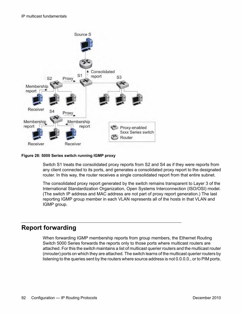
Figure 28: 5000 Series switch running IGMP proxy
Switch S1 treats the consolidated proxy reports from S2 and S4 as if they were reports fromany client connected to its ports, and generates a consolidated proxy report to the designatedrouter. In this way, the router receives a single consolidated report from that entire subnet.
The consolidated proxy report generated by the switch remains transparent to Layer 3 of theInternational Standardization Organization, Open Systems Interconnection (ISO/OSI) model.(The switch IP address and MAC address are not part of proxy report generation.) The lastreporting IGMP group member in each VLAN represents all of the hosts in that VLAN andIGMP group.
Report forwardingWhen forwarding IGMP membership reports from group members, the Ethernet RoutingSwitch 5000 Series forwards the reports only to those ports where multicast routers areattached. For this the switch maintains a list of multicast querier routers and the multicast router(mrouter) ports on which they are attached. The switch learns of the multicast querier routers bylistening to the queries sent by the routers where source address is not 0.0.0.0., or to PIM ports.
IP multicast fundamentals
92 Configuration — IP Routing Protocols December 2010

Static mrouter port and nonquerierIf two IGMP routers are active on a VLAN, the router with the lower IP address is the querier,and the router with the higher IP address operates as a nonquerier. Only querier routersforward IGMP queries on the VLAN; nonqueriers do not forward IGMP queries. IGMP snoopconsiders the port on which the IGMP query is received as the active IGMP multicast router(mrouter) port. IGMP snoop is not aware of nonquerier IGMP routers.
By default, IGMP snoop forwards reports to the IGMP querier router only. To allow the switchto forward reports to the nonquerier router as well, you can configure the port connected to thenonquerier as a static mrouter port.
The following figure shows how static mrouter ports operate. Here, the Ethernet Routing Switch5000 Series has port members 5/1 and 6/1 connected to IGMP routers in VLAN 10. In thiscase, router 1 is the IGMP querier because it has a lower IP address than router 2. Router 2is then considered the nonquerier.
By default, the switch learns of the multicast querier routers by listening to the IGMP queries. Inthis case, port 6/1 connected to querier router 1 is identified as an mrouter port.
To forward reports to IGMP router 2 as well, you can configure port 5/1 on the switch as a staticmrouter port. In this case, the IGMP reports are forwarded to both routers.
Important:Configure a static mrouter port only when multiple multicast routers are present that are notdirectly attached to one another but are directly attached to the VLAN (technically an invalidconfiguration). If multicast routers have an existing route between them (the validconfiguration) and this field is configured, a multicast loop forms.
Figure 29: Static mrouter port and nonquerier
Unknown multicast packet filteringWith IGMP snoop enabled, if the switch receives multicast packets with destination addressesthat it has not already registered using IGMP reports, the switch floods all such packets to all
IGMP snooping
Configuration — IP Routing Protocols December 2010 93
ports on the VLAN. All unknown multicast streams of a group are flooded on the VLAN until atleast one port in the VLAN becomes a member of that group.
On the Ethernet Routing Switch 5000 Series, you can enable the unknown multicast filteringfeature so that the unknown multicast packets are not flooded on the VLAN. To enable unknownmulticast filtering, you can use the vlan igmp unknown-mcast-no-flood ACLIcommand.
With this feature enabled, the switch forwards all unknown multicast traffic to IGMP static anddynamic mrouter ports.
Avaya recommends that you enable this feature when IGMP snooping is enabled. Usersettings for the unknown multicast filtering feature are stored in NVRAM.
Related topics:Allowing a multicast MAC address to flood VLANs on page 94
Allowing a multicast MAC address to flood VLANs
The unknown multicast filtering feature introduces a potential problem when you place a Layer2 VLAN between two Layer 3 switches that exchange protocol packets (such as OSPF). Sincethe protocols do not join a multicast group, the IGMP snooping process cannot identify theirmulticast MAC addresses. The system drops the protocol packets due to the effect of theunknown multicast filtering feature. The two Layer 3 switches can never establish adjacenciesand the OSPF protocol fails.
Using the vlan igmp unknown-mcast-allow-flood ACLI command, you can specifymulticast MAC addresses or multicast IP addresses that need to be flooded on a VLAN evenwhen the unknown multicast filtering feature is enabled. The specified MAC or IP addressesare added to the allow-flood table for the specified VLAN. Any matching packets are floodedon all ports of a VLAN.
Because multicast MAC addresses starting with 01:00:5E map to multiple IP addresses, youcannot specify 01:00:5E MAC addresses in the allow-flood table. Instead, you must specifythe required multicast IP address to flood. For instance, you cannot add MAC address01.00.5E.01.02.03 to the allow-flood table, but you can add IP address 224.1.2.3.
For all other types of MAC address, you can enter the MAC address directly to allow flooding.For example, to allow flooding of STP BPDUs, you can specify MAC address01:80:c2:00:00:00.
IP multicast fundamentals
94 Configuration — IP Routing Protocols December 2010
IGMP snooping configuration rulesThe IGMP snooping feature operates according to specific configuration rules. Whenconfiguring the switch for IGMP snooping, consider the following rules that determine how theconfiguration reacts in any network topology:
• While PIM-SM supports up to 1000 multicast groups, the maximum number of groupssupported with IGMP snooping are as follows:
- Ethernet Routing Switch 5510: 240 groups
- Ethernet Routing Switch 5520 and 5530: 492 groups
- Ethernet Routing Switch 5600: 992 groups
In a hybrid stack that includes ERS5510 units, you can use the IGMP mode to setERS5510 capability for the stack. ERS5510 mode supports up to 240 groups. Or you canconfigure the non-5510 mode.
When you configure the non-5510 mode, the system disables IGMP functionality on theERS5510, and the system automatically sets the maximum number of groups to 492, ifan ERS 5520 or ERS 5530 is present in the stack (hybrid), or to 992 groups for a pureERS 5600 stack.
The system purges existing groups when you change the IGMP mode.
If the multicast group table reaches its limit, the system cannot add a new entry with aJOIN message or add a new sender identifying a new group and the hardware discardsthe multicast stream from the new sender. New entries can be added again once the tableis not full.
Because all multicast forwarding shares the same hardware resources, when you deployPIM the actual number of supported IGMP groups can be reduced.
• When you use IGMPv1 or IGMPv2 Snooping mode, the maximum number of IGMPgroups is determined by the IGMP operational mode. When you use IGMPv3 Snoopingmode, the maximum number of IGMP groups is determined by the types of IGMPv3 reportpackets processed. Each new IGMPv3 group or source consumes 1 hardware table entryIf the IGMPv3 source is for a group that has never been seen by the IGMP application,then an additional hardware table entry is consumed.
• When you specify MAC addresses or IP addresses to be flooded on the switch, thespecified MAC or IP addresses are flooded on all ports of the specified VLAN. In addition,if multicast join messages are received for IP addresses specified in the allow-flood table,these IP addresses are not displayed in the IGMP group membership table. In otherwords, the switch does not learn groups if they are specified in the allow-flood table.
• A port that is configured for port mirroring cannot be configured as a static mrouter port.
The switch does support mirroring of IGMP control packets as well as multicast datapackets.
IGMP snooping
Configuration — IP Routing Protocols December 2010 95
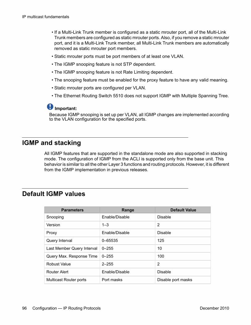
• If a Multi-Link Trunk member is configured as a static mrouter port, all of the Multi-LinkTrunk members are configured as static mrouter ports. Also, if you remove a static mrouterport, and it is a Multi-Link Trunk member, all Multi-Link Trunk members are automaticallyremoved as static mrouter port members.
• Static mrouter ports must be port members of at least one VLAN.
• The IGMP snooping feature is not STP dependent.
• The IGMP snooping feature is not Rate Limiting dependent.
• The snooping feature must be enabled for the proxy feature to have any valid meaning.
• Static mrouter ports are configured per VLAN.
• The Ethernet Routing Switch 5510 does not support IGMP with Multiple Spanning Tree.
Important:Because IGMP snooping is set up per VLAN, all IGMP changes are implemented accordingto the VLAN configuration for the specified ports.
IGMP and stackingAll IGMP features that are supported in the standalone mode are also supported in stackingmode. The configuration of IGMP from the ACLI is supported only from the base unit. Thisbehavior is similar to all the other Layer 3 functions and routing protocols. However, it is differentfrom the IGMP implementation in previous releases.
Default IGMP values
Parameters Range Default ValueSnooping Enable/Disable Disable
Version 1–3 2
Proxy Enable/Disable Disable
Query Interval 0–65535 125
Last Member Query Interval 0–255 10
Query Max. Response Time 0–255 100
Robust Value 2–255 2
Router Alert Enable/Disable Disable
Multicast Router ports Port masks Disable port masks
IP multicast fundamentals
96 Configuration — IP Routing Protocols December 2010
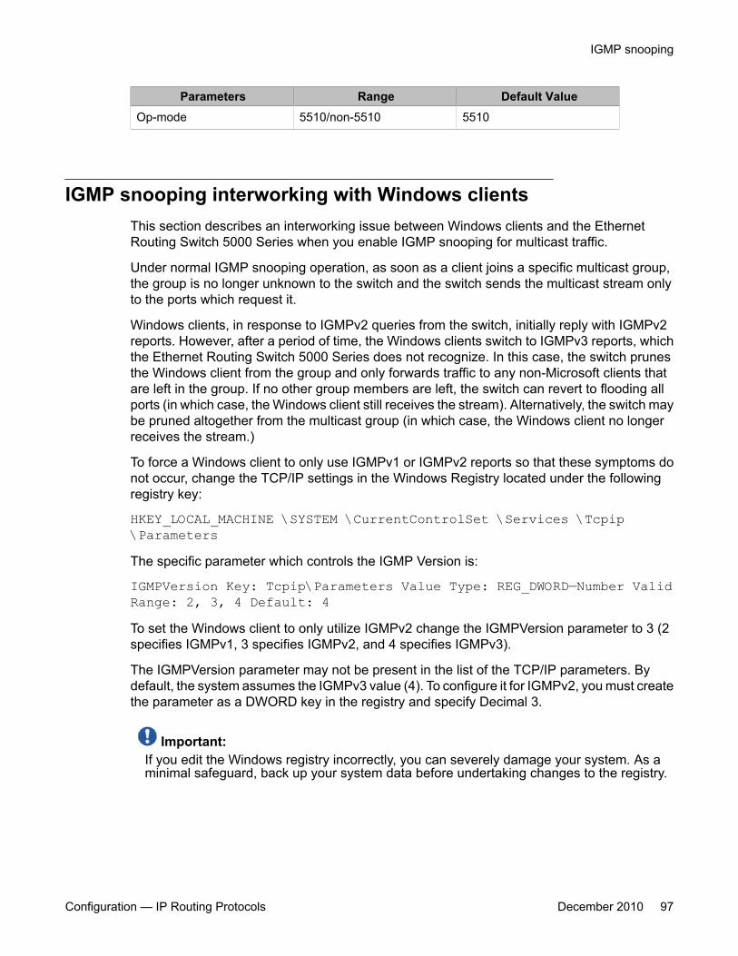
Parameters Range Default ValueOp-mode 5510/non-5510 5510
IGMP snooping interworking with Windows clientsThis section describes an interworking issue between Windows clients and the EthernetRouting Switch 5000 Series when you enable IGMP snooping for multicast traffic.
Under normal IGMP snooping operation, as soon as a client joins a specific multicast group,the group is no longer unknown to the switch and the switch sends the multicast stream onlyto the ports which request it.
Windows clients, in response to IGMPv2 queries from the switch, initially reply with IGMPv2reports. However, after a period of time, the Windows clients switch to IGMPv3 reports, whichthe Ethernet Routing Switch 5000 Series does not recognize. In this case, the switch prunesthe Windows client from the group and only forwards traffic to any non-Microsoft clients thatare left in the group. If no other group members are left, the switch can revert to flooding allports (in which case, the Windows client still receives the stream). Alternatively, the switch maybe pruned altogether from the multicast group (in which case, the Windows client no longerreceives the stream.)
To force a Windows client to only use IGMPv1 or IGMPv2 reports so that these symptoms donot occur, change the TCP/IP settings in the Windows Registry located under the followingregistry key:
HKEY_LOCAL_MACHINE \SYSTEM \CurrentControlSet \Services \Tcpip\ParametersThe specific parameter which controls the IGMP Version is:
IGMPVersion Key: Tcpip\Parameters Value Type: REG_DWORD—Number ValidRange: 2, 3, 4 Default: 4To set the Windows client to only utilize IGMPv2 change the IGMPVersion parameter to 3 (2specifies IGMPv1, 3 specifies IGMPv2, and 4 specifies IGMPv3).
The IGMPVersion parameter may not be present in the list of the TCP/IP parameters. Bydefault, the system assumes the IGMPv3 value (4). To configure it for IGMPv2, you must createthe parameter as a DWORD key in the registry and specify Decimal 3.
Important:If you edit the Windows registry incorrectly, you can severely damage your system. As aminimal safeguard, back up your system data before undertaking changes to the registry.
IGMP snooping
Configuration — IP Routing Protocols December 2010 97

IGMP Send QueryA multicast query router communicates with hosts on a local network by sending IGMP queries.This router periodically sends a general query message to each local network of the router.This is standard multicast behavior.
Avaya recommends that each VLAN using IGMP multicast have a router performing multicastqueries. This router typically has PIM or DVMRP enabled. Currently, PIM is only available forstandalone devices. Networks with no standalone devices currently have no capability forimplementing the pruning of IGMP traffic. The IGMP Send Query functionality allows a switch orstack to be configured as an active query router without the need for dedicating a standaloneswitch in each network to the task.
There are several behavioral differences between a traditional query router and a switch orstack using the IGMP Send Query functionality. The following differences should be noted:
• There is no election process. When a switch or stack restarts, the code will send somequeries as part of IGMP start up. This process will stop other devices sending querieswhile they detect the new device starting up. The last active device sending queries onthe network is the active one. This is not the case with Layer 3 IGMP behavior.
• If the current active device stops sending queries, a timeout period must elapse beforeanother device takes over. This may result in an ageout of groups, and subsequentflooding, before a new query is sent and the pruning process restarts. This occurs onlyduring the transition between active query devices. Once the new device is established,queries will be sent as configured in the Query Interval and Robust Values fields.
• Multiple active query devices are not supported. Enabling multiple devices establishesone active device and other devices listening to take over should the active device fail.
IGMP Send Query functionality can only be enabled when IGMP snooping is active on theswitch or stack.
Successful deployment of this feature is dependant on the addition of IP addresses from alldevices in the IGMP domain. This is true even when non-management VLANs are used.
Protocol Independent Multicast-Sparse ModeProtocol Independent Multicast-Sparse Mode (PIM-SM), as defined in RFC 2362, supportsmulticast groups spread out across large areas of a company or the Internet. Unlike dense-mode protocols, such as Distance Vector Multicast Routing Protocol (DVMRP), that initiallyflood multicast traffic to all routers over an entire internetwork, PIM-SM sends multicast trafficonly to routers that belong to a specific multicast group and that choose to receive the traffic.
IP multicast fundamentals
98 Configuration — IP Routing Protocols December 2010
This technique reduces traffic flow over wide area network (WAN) links and minimizes theoverhead costs of processing unwanted multicast packets.
Dense-mode protocols that use the flood-and-prune technique are efficient when receivers aredensely populated; however, for sparsely populated networks, PIM-SM is more efficient.
PIM-SM is independent of any specific unicast routing protocol, but it does require the presenceof a unicast routing protocol, such as RIP or OSPF. PIM-SM uses the information from theunicast routing table to create and maintain multicast trees that allow PIM-enabled routers tocommunicate.
A PIM-SM network consists of several multipoint data streams, each targeted to a smallnumber of LANs in the internetwork. For example, customers whose networks consist ofmultiple hosts on different LANs in many dispersed locations can use PIM-SM tosimultaneously access a video data stream, such as a video teleconference.
In some cases, PIM-SM stream initialization can take several seconds.
Related topics:PIM-SM concepts and terminology on page 99PIM-SM shared trees and shortest-path trees on page 103Source-to-RP SPT on page 107Register suppression timeout on page 107Receivers leaving a group on page 108PIM assert on page 108
PIM-SM concepts and terminologyThe following sections describe PIM-SM concepts and terminology.
Related topics:PIM-SM sources and receivers on page 100PIM neighbor discovery on page 100Required elements for PIM-SM operation on page 100Designated router on page 100Rendezvous-point router on page 101Active RP selection on page 101Static RP on page 102Bootstrap router on page 103Active BSR selection on page 103
Protocol Independent Multicast-Sparse Mode
Configuration — IP Routing Protocols December 2010 99
PIM-SM sources and receivers
With PIM-SM, a host can be a source, a receiver, or both:
• A source, also known as a sender, sends multicast data to a multicast group.
• A receiver receives multicast data from one or several sources that send data to amulticast group.
PIM neighbor discovery
To discover neighbors, PIM routers exchange PIM hello packets. When PIM is enabled on arouter interface, the interface forwards PIM hello packets to the all-PIM-Routers multicastaddress (224.0.0.13).
Each PIM hello packet contains a holdtime that specifies the period that the receiving routermust wait before declaring the neighbor unreachable. This holdtime is configurable as thequery interval for each interface. Each PIM interface continues to send hello messages at theconfigured query interval.
Required elements for PIM-SM operation
PIM-SM operates in a domain of contiguous routers that have PIM-SM enabled. Each routermust run an underlying unicast routing protocol to provide routing table information to PIM-SM.
Each PIM-SM domain requires the following routers:
• designated routers (DR)
• rendezvous-point (RP) router
• bootstrap router (BSR)
Within the PIM-SM domain, each group can have only one active RP router and one activeBSR. The active BSR is chosen among a list of candidate-BSRs, and the active RP is chosenamong a list of candidate-RPs. You can configure the Ethernet Routing Switch 5000 Series tobe a candidate-BSR, a candidate-RP, or both.
Designated router
The designated router (DR) serves as the link from sources and receivers to the other routers inthe PIM-SM domain. There are typically multiple DRs in a PIM-SM domain.
IP multicast fundamentals
100 Configuration — IP Routing Protocols December 2010
On any subnet, the DR is the PIM-SM router with the highest IP address. The DR performsthe following tasks:
• sends register messages to the RP router on behalf of directly connected sources
• sends join/prune messages to the upstream router on behalf of directly connectedreceivers
• maintains information about the status of the active RP router
Important:You cannot manually configure a router as a DR. If a router is enabled with PIM-SM and itis the PIM-SM router with the highest IP address on the subnet, it automatically acts as theDR for any directly attached sources and receivers, as required.
Rendezvous-point router
A multicast group has only one active rendezvous-point (RP) router. The RP performs thefollowing tasks:
• manages one or several IP Multicast groups
• becomes the root for the shared tree to these groups
• accepts join messages from receivers
• registers sources that want to send data to group members
• forwards data to the group
At the RP router, receivers meet new sources. Sources register with the RP to identifythemselves to other routers on the network; receivers join the RP-based multicast distributiontree to learn about new sources.
For each multicast group, PIM-SM builds a multicast distribution tree, known as the sharedtree, with the RP at the root and all receivers downstream from the RP. Although you canphysically locate the RP anywhere on the network, the RP must be as close to the source aspossible.
Active RP selection
The active RP is calculated among a list of candidate RPs (C-RP). Within each group, you canconfigure multiple PIM-SM routers as C-RPs.
Each C-RP sends unicast advertisement messages to the BSR. The BSR creates a list of C-RPs, which is referred to as the RP set. The BSR periodically sends bootstrap messages thatcontain the complete RP set to all routers in the group. Each router uses the same hash functionto determine which router in the set is going to be the RP (given the same RP set, each router
Protocol Independent Multicast-Sparse Mode
Configuration — IP Routing Protocols December 2010 101
points to the same RP). If the active RP fails, routers can recalculate the active RP using thereduced set of C-RPs.
Static RP
You can use the static RP feature to configure a static entry for an RP. Static RP-enabledrouters do not learn about C-RPs through the BSR. With static RP enabled, the router ignoresBSR messages and loses all dynamically learned BSR information. When you configure staticRP entries, the router adds them to the RP set as though they are learned through the BSR.
You can use the static RP feature when dynamic learning is not needed, typically in smallnetworks or for security reasons. You can also enable static RP to allow communication withrouters from other vendors that do not use the BSR mechanism. Some vendors use earlyimplementations of PIM-SMv1 that do not support the BSR or proprietary mechanisms like theCisco Auto-RP. For a network to work properly with static RP, all the routers in the network(including routers from other vendors) must be configured with the same RP or RPs, if severalRPs are present in the network.
To configure static RP on a router, the next hop of the unicast route toward the static RP must bea PIM-SM neighbor. If a route change causes the next hop toward an already configured staticRP to become a non-PIM neighbor, the PIM-SM protocol fails on the router. The state of theconfigured RP on the router remains invalid until it can be reached through a PIM neighbor.
To avoid a single point of failure, you can also configure redundant static RPs.
When you configure a static RP, take into account the following considerations:
• You cannot configure a static RP-enabled router as a BSR or as a C-RP.
• All dynamically learned BSR information is lost. However, if you disable static RP, therouter clears the static RP information and regains the BSR functionality.
• Static RPs do not age; that is, they cannot time out.
• Routers do not advertise static RPs; therefore, if a new PIM-SM neighbor joins thenetwork, this new neighbor does not know about the static RP unless you configure theneighbor with that static RP.
• All the routers in the network (including routers from other vendors) must map to the sameRP.
• In a PIM-SM domain with both static and dynamic RP routers, you cannot configure one ofthe (local) interfaces of the static RP routers as RP.
• To avoid a single point of failure, you can configure redundant static RPs for the samegroup prefix. If a mix of Avaya and other vendor routers exist across the network, ensurethat all routers use the same active RP because other vendors can use differentalgorithms to elect the active RP. The Ethernet Routing Switch 5000 Series uses the hashfunction defined in the PIM-SM standard to elect the active RP, with the highest C-RP
IP multicast fundamentals
102 Configuration — IP Routing Protocols December 2010
address selected to break a tie. Other vendors can use the lowest IP address to breakthe tie.
• You cannot assign a priority to static RP entries, although the Ethernet Routing Switchaccepts priority values from non-Avaya routers for interoperability.
• A static RP that you configure on the router is alive as long as the router has a unicastroute to the network for the static RP. If the router loses this route, it invalidates the staticRP and uses the hash algorithm to remap all affected groups. If the router regains thisroute, it validates the static RP and uses the hash algorithm to remap the affected groups.
Bootstrap router
The bootstrap router (BSR) receives advertisement messages from the C-RPs. The BSR addsthe C-RPs and their group prefixes to the RP set. The BSR sends bootstrap messages thatcontain the complete RP set to all routers in the domain to allow them to learn group-to-RPmappings.
Only one BSR exists for each PIM-SM domain.
Active BSR selection
Within a PIM-SM domain, you can configure a set of routers as candidate BSRs (C-BSR). TheC-BSR with the highest configured priority becomes the BSR for the domain. If two C-BSRshave equal priority, the candidate with the higher IP address becomes the BSR. If you add anew C-BSR with a higher priority to the domain, it automatically becomes the new BSR.
PIM-SM shared trees and shortest-path treesPIM-SM uses two types of multicast distribution trees to deliver data packets to groupmembers: shared trees and shortest-path trees (SPT).
Related topics:Shared tree on page 104Traffic forwarding with the shared tree on page 104Shortest path tree on page 105Receiver joining a group and receiving data from a source on page 106
Protocol Independent Multicast-Sparse Mode
Configuration — IP Routing Protocols December 2010 103
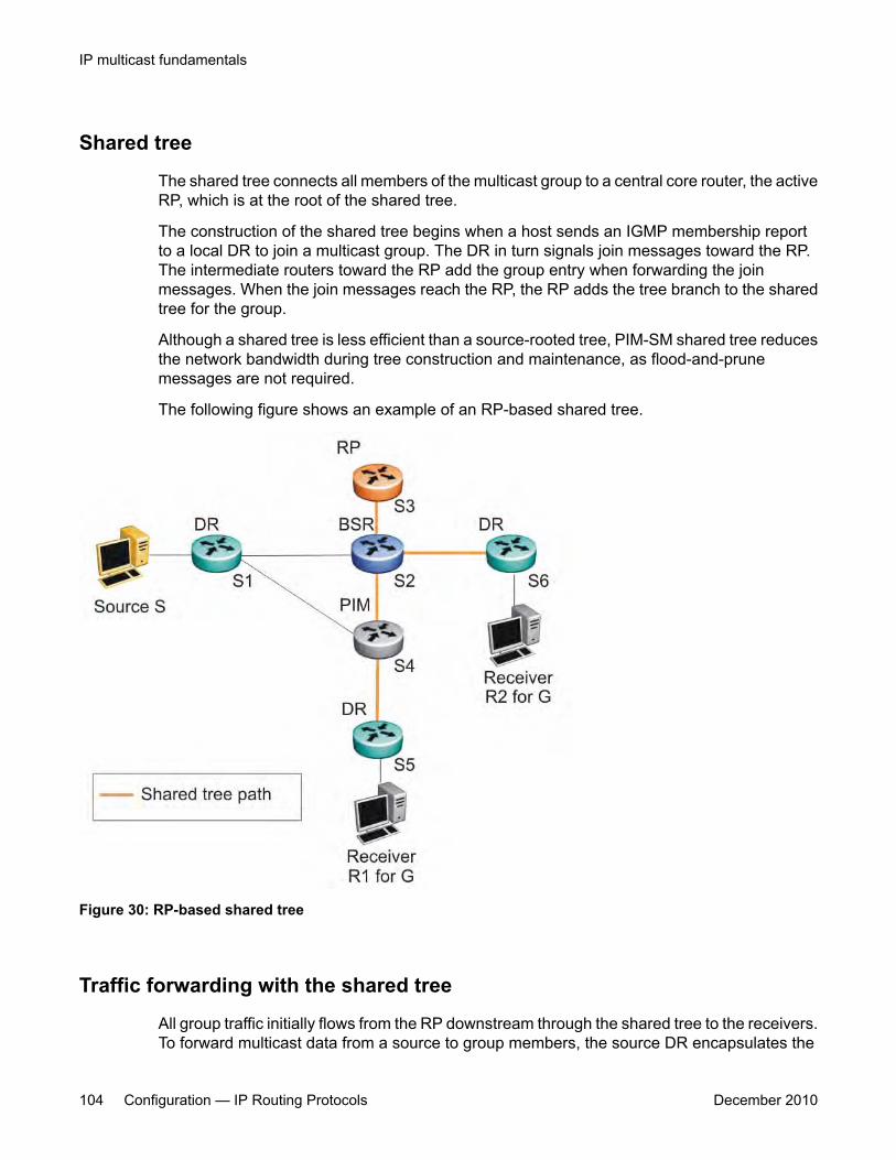
Shared tree
The shared tree connects all members of the multicast group to a central core router, the activeRP, which is at the root of the shared tree.
The construction of the shared tree begins when a host sends an IGMP membership reportto a local DR to join a multicast group. The DR in turn signals join messages toward the RP.The intermediate routers toward the RP add the group entry when forwarding the joinmessages. When the join messages reach the RP, the RP adds the tree branch to the sharedtree for the group.
Although a shared tree is less efficient than a source-rooted tree, PIM-SM shared tree reducesthe network bandwidth during tree construction and maintenance, as flood-and-prunemessages are not required.
The following figure shows an example of an RP-based shared tree.
Figure 30: RP-based shared tree
Traffic forwarding with the shared tree
All group traffic initially flows from the RP downstream through the shared tree to the receivers.To forward multicast data from a source to group members, the source DR encapsulates the
IP multicast fundamentals
104 Configuration — IP Routing Protocols December 2010

multicast packets in Register messages that it then unicasts to the RP. The RP decapsulatesthe Register messages, and then forwards the multicast data to any existing group membersdownstream using the shared tree.
In the shared tree, the RP router represents a potential bottleneck and a single point of failure.As a result, PIM-SM allows local DRs to bypass the share tree and switch to a source-rootedshortest path tree.
Shortest path tree
When multicast packets arrive at the receiver DR, the DR can identify the IP address of thesource. If the DR determines that the shared tree is not the optimal path back to the source, itsends a join message directly to the source DR. This new direct path from the source to thereceiver DR is the source-based shortest-path tree (SPT). When the receiver DR startsreceiving traffic directly from the source, it sends a prune message to the RP to stop sendingmessages over the shared tree.
With the 5000 Series switches, the DR switches to the SPT after it receives the first packetfrom the RP.
The following figure shows an example of a source-based SPT.
Protocol Independent Multicast-Sparse Mode
Configuration — IP Routing Protocols December 2010 105
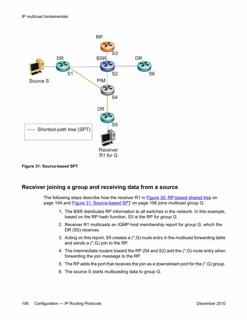
Figure 31: Source-based SPT
Receiver joining a group and receiving data from a source
The following steps describe how the receiver R1 in Figure 30: RP-based shared tree onpage 104 and Figure 31: Source-based SPT on page 106 joins multicast group G:
1. The BSR distributes RP information to all switches in the network. In this example,based on the RP hash function, S3 is the RP for group G.
2. Receiver R1 multicasts an IGMP host membership report for group G, which theDR (S5) receives.
3. Acting on this report, S5 creates a (*,G) route entry in the multicast forwarding tableand sends a (*,G) join to the RP.
4. The intermediate routers toward the RP (S4 and S2) add the (*,G) route entry whenforwarding the join message to the RP.
5. The RP adds the port that receives the join as a downstream port for the (*,G) group.
6. The source S starts multicasting data to group G.
IP multicast fundamentals
106 Configuration — IP Routing Protocols December 2010
7. The source DR (S1) encapsulates the data in a Register message that it unicaststo the RP (S3).
8. S3 decapsulates the multicast data and forwards it down the shared tree. Groupmember S5 receives the data and forwards it to receiver R1.
9. After S5 receives the first packet, it knows the IP address for the source. S5 createsan (S,G) entry in the multicast forwarding table, and sends a (S,G) join to the source.All intermediate routers along the path to the source create the (S,G) entry. S5 alsoprunes itself from the RP shared tree.
10. S1 forwards multicast packets to S5 over the SPT.
Important:The PIM-SM topology shown in this example is simplified and is not the best design for anetwork if the source and receiver are placed as shown. In general, RPs are placed as closeas possible to sources.
Source-to-RP SPTRather than continue to receive multicast traffic from the source through unicast Registermessages, the RP also switches to a source-based SPT. After it receives the first sourceRegister message, it sends a join message to the source DR to receive the data through amulticast rather than unicast stream. After it receives the first multicast packet over the SPT,the RP sends a register-stop message to the source to stop sending the data in registermessages.
On the Ethernet Routing Switch 5000 Series, the DR only forwards the first multicast packetas a Register packet to the RP, and immediately goes into discard mode until it receives a joinmessage from the RP. During this time, there is brief data loss of the multicast stream.
After the source DR processes the join message, the DR forwards native multicast packets tothe RP over the SPT path.
Register suppression timeoutIf a source registers with an RP, but no receivers are registered to receive the traffic, the RPsends a register-stop to the source.
After receiving a register-stop message from the RP, the source DR starts a registersuppression timer (the default value is 60 seconds).
Shortly before the register suppression timer expires, the source DR sends a register messagewith no encapsulated packets to the RP router. This null-register message prompts the RProuter to determine whether new downstream receivers joined the group. If no new membershave joined the group, the RP router sends another register-stop message to the DR for the
Protocol Independent Multicast-Sparse Mode
Configuration — IP Routing Protocols December 2010 107
source, and the register suppression timer restarts. In this way, the DR can regularly poll theRP to determine whether any new members have joined the group without forwarding largertraffic packets to the RP unnecessarily.
A lower register suppression timeout produces traffic bursts from the DR more frequently,whereas with a higher value, new receivers face a longer join latency.
Receivers leaving a groupIf all directly connected members of a multicast group leave or time out, and no downstreammembers remain, the DR sends a prune message upstream and PIM-SM deletes the routeentry after that entry times out.
PIM assertWhen a PIM router connects a source to a LAN segment and it detects a second PIM routerwith a route to the same source on the same segment, the routers exchange Assert messagesto determine which router is to forward the multicast stream on the segment.
PIM passive interfacesYou can specify whether you want a PIM interface to be active or passive. The default is active.Active interfaces can transmit and receive PIM control traffic. A passive interface drops all PIMcontrol traffic, thereby reducing the load on the system. This feature is useful when you havea high number of PIM interfaces and these interfaces are connected to end users, not to otherrouters.
A PIM passive interface drops any messages of the following type:
• Hello
• Join/Prune
• Register
• Register-Stop
Important:A device can send Register and Register-Stop messages to a PIM passive interface,but that interface cannot send out these messages.
IP multicast fundamentals
108 Configuration — IP Routing Protocols December 2010

• Assert
• Candidate-RP-Advertisement
• Bootstrap
If a PIM passive interface receives any of these types of messages, it drops them, and theswitch logs a message, detailing the type of protocol message received and the IP address ofthe sending device. These log messages help to identify the device that is performing routingon the interface, which is useful if you must disable a device that is not operating correctly.
The PIM passive interface maintains information through the IGMP protocol about hosts thatare related to senders and receivers, but the interface does not maintain information about anyPIM neighbors.
You can also use the PIM passive interface feature as a security measure to prevent routingdevices from becoming attached and participating in the multicast routing of the network.
You can configure a PIM passive interface as a BSR or an RP, although Avaya does notrecommend these options.
Important:Before you change the state (active or passive) of a PIM interface, disable PIM on thatinterface. Disabling PIM prevents instability in the PIM operations, especially whenneighbors are present or streams are received.
PIM-SM capabilities and limitationsThe following list describes the capabilities and limitations of PIM-SM on the Ethernet RoutingSwitch 5000 Series.
• PIM-SM is not supported on the Ethernet Routing Switch 5510 platform.
• PIM-SM is supported in a stack but PIM has no effect on ERS 5510 units in a stack. Nativemulticast streams and PIM protocol packets ingressed on the ERS 5510 are flooded.
• You cannot allow the PIM-SM shared path tree or SPT to span across any Layer 2switches. Be sure to implement your topology such that the unicast routes from any DRto the PIM RP and to all multicast sources travel through directly-connected PIMneighbors only. Otherwise, network issues may arise.
• PIM-SM cannot be enabled on brouter ports.
• PIM-SM is not supported over SMLT or IST.
• PIM-SM is not supported on a secondary IP of a Layer 3 VLAN.
• A maximum of 32 PIM-SM active interfaces are supported.
• A maximum of 64 total PIM-SM interfaces are supported.
PIM-SM capabilities and limitations
Configuration — IP Routing Protocols December 2010 109

• You can configure only one Candidate-RP per switch for any number of groups (up to 50group ranges).
• You can configure static RP for up to 50 groups.
• You can configure every PIM-enabled interface as Candidate-BSR.
• PIM-SM supports forwarding of the multicast stream on ECMP, but traffic balancing is notsupported. PIM-SM picks one route for its RPF check and uses it for all streams whenjoining a source on this route.
• On the Ethernet Routing Switch 5600, up to 992 (S,G) entries are supported.
• On the Ethernet Routing Switch 5500, up to 492 (S,G) entries are supported. On a hybridstack that contains ERS 5500 and ERS 5600 units, up to 492 (S,G) entries are supported.
• Some Layer 2 IGMP snooping-enabled switches can learn a maximum of 240 groupsfrom clients. However, a PIM router can learn more than 240 groups if it is connected tomore than one snooping-enabled switch. In this case, if each Layer 2 switch learns 240groups, the number of groups the PIM router learns is: 240 * number of Layer 2 switches.However, the number of (*,G) entries on the PIM router is limited to 960 for a 5600 switchand 490 for a 5500 switch.
• If a PIM server and IGMP receiver are in the same VLAN, you cannot connect them tothe same port. To have a PIM server and IGMP receiver on the same port, the server andreceiver must be in different tagged VLANs.
• With static RP, priority is not supported in a pure Avaya-only solution. If the 5000 Seriesswitch is connected to a non-Avaya router that is running static RP, then the 5000 Seriesswitch can learn the priority as advertised by the non-Avaya router.
• Passive interfaces are supported on the edge only (where the port only has connections toeither clients or servers). Make sure that any passive interfaces are not in the path of anyPIM RPF paths, otherwise the network may not work.
Enabling or disabling routing with IGMP enabledYou cannot enable PIM-SM and IGMP snooping on the same VLAN. As a result, when enablingor disabling routing on a VLAN, the IGMP functionality operates as follows:
• When a VLAN is changed from Layer 3 to Layer 2, IGMP reduces the functionality tosnooping.
• When an IGMP snooping-enabled VLAN is changed from Layer 2 to Layer 3, the switchcontinues to support snooping until you enable PIM-SM.
• When a Layer 3 VLAN has v1 and v2 snooping enabled and you try to enable PIM-SM,the switch displays a warning message to disable snooping before enabling PIM-SM.
IP multicast fundamentals
110 Configuration — IP Routing Protocols December 2010
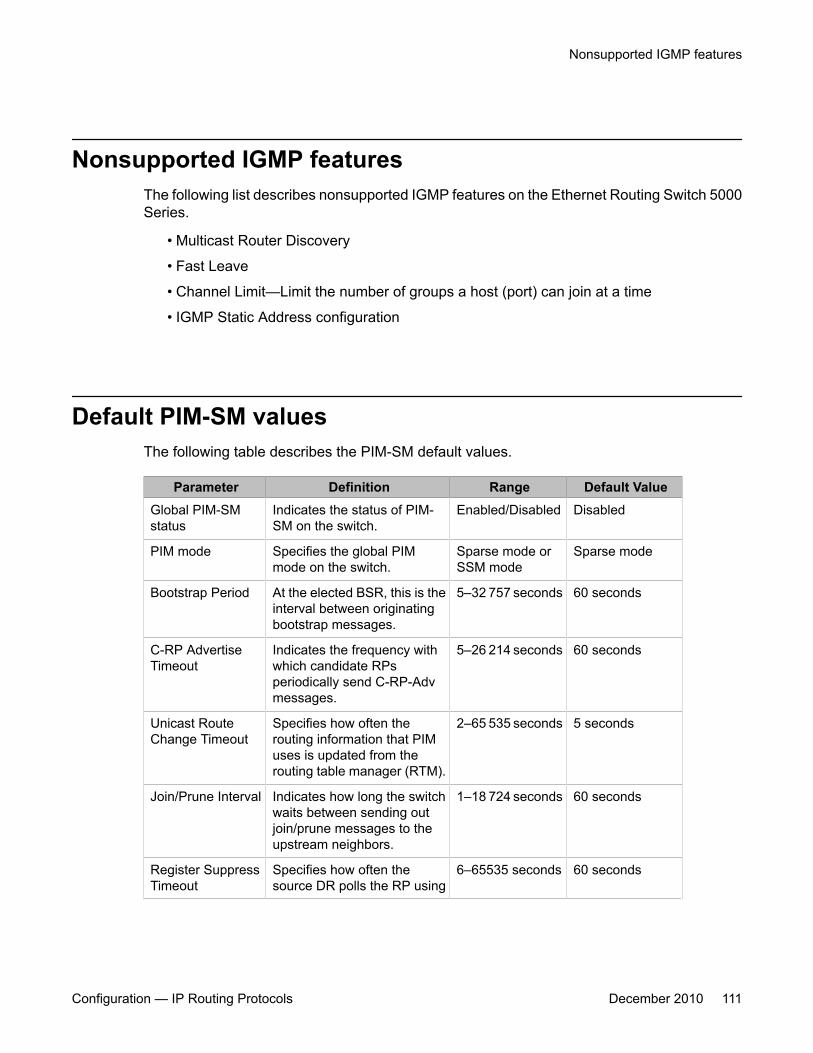
Nonsupported IGMP featuresThe following list describes nonsupported IGMP features on the Ethernet Routing Switch 5000Series.
• Multicast Router Discovery
• Fast Leave
• Channel Limit—Limit the number of groups a host (port) can join at a time
• IGMP Static Address configuration
Default PIM-SM valuesThe following table describes the PIM-SM default values.
Parameter Definition Range Default ValueGlobal PIM-SMstatus
Indicates the status of PIM-SM on the switch.
Enabled/Disabled Disabled
PIM mode Specifies the global PIMmode on the switch.
Sparse mode orSSM mode
Sparse mode
Bootstrap Period At the elected BSR, this is theinterval between originatingbootstrap messages.
5–32 757 seconds 60 seconds
C-RP AdvertiseTimeout
Indicates the frequency withwhich candidate RPsperiodically send C-RP-Advmessages.
5–26 214 seconds 60 seconds
Unicast RouteChange Timeout
Specifies how often therouting information that PIMuses is updated from therouting table manager (RTM).
2–65 535 seconds 5 seconds
Join/Prune Interval Indicates how long the switchwaits between sending outjoin/prune messages to theupstream neighbors.
1–18 724 seconds 60 seconds
Register SuppressTimeout
Specifies how often thesource DR polls the RP using
6–65535 seconds 60 seconds
Nonsupported IGMP features
Configuration — IP Routing Protocols December 2010 111

Parameter Definition Range Default Valuedata packets encapsulated inRegister messages.
Data Discard Timer After the router forwards thefirst source packet to the RP,this value specifies how long(in seconds) the routerdiscards subsequent sourcedata while waiting for a joinfrom the RP.
5–65 535 seconds 60 seconds
Static RP Indicates the status of staticRP on the switch.
Enabled/Disabled Disabled
Forward CacheTimeout
Indicates the PIM-SM forwardcache expiry value. This valueis used in aging PIM-SMmroutes.
10–86 400seconds
210 seconds
VLAN PIM-SMstatus
Indicates the status of PIM-SM on the VLAN.
Enabled/Disabled Disabled
Hello Interval Sets the hello interval for theVLAN.
0–18 724 seconds 30 seconds
Interface Type Sets the interface type on aparticular VLAN.
• active: allowsPIM-SM controltraffic to betransmitted andreceived.
• passive:prevents PIM-SM controltraffic frombeingtransmitted orreceived.
Active
Candidate-BSRpriority
Indicates whether the router isacting as a C-BSR on aparticular VLAN, and if so, thepriority associated with it.
0 to 255 –1 (indicates thatthe interface is nota Candidate BSR)
Candidate-RP Indicates whether the VLANinterface is configured as a C-RP. With the Ethernet RoutingSwitch 5000 Series, you canconfigure only one localinterface as a C-RP for anynumber of groups.
IP address of theC-RP interfaceand theassociated groupand mask.
None defined(disabled)
IP multicast fundamentals
112 Configuration — IP Routing Protocols December 2010
Chapter 5: IPv6 routing fundamentals
This chapter provides an introduction to IPv6 routing and the IPv6 routing features supported on the AvayaEthernet Routing Switch 5000 Series.
Navigation• IPv6 routing features on page 113
• Host autoconfiguration on page 114
• IPv6 static routes on page 115
• Management route on page 117
• IPv6 DHCP Relay on page 118
• IPv6-in-IPv4 tunnels on page 119
IPv6 routing featuresThe Ethernet Routing Switch 5000 Series provides support for configurable IPv6 static routesand per-VLAN IPv6 routes.
Supported features include the following:
• Multiple configurable IPv6 interfaces associated with VLANs
• One IPv6 global addresses (automatically inserted into the routing table) per IPv6interface
• Multiple configurable static route entries in the IPv6 routing table
• Router functionality based on the routing table constructed using the two precedingmethods listed
The ERS 5510, 5520 and 5530 do not support IPv6 routing, non-local IPv6 static routes, nordo hybrid stacks containing those units.
Configuration — IP Routing Protocols December 2010 113
The scaling limits on the routing table are as follows.
• 512 maximum IPv6 static routes
• 256 maximum IPv6 interfaces
Host autoconfigurationThe Avaya Ethernet Routing Switch 5000 Series supports the Neighbor Discovery Protocol forIPv6. Using Router Advertisements forwarded by the switch, hosts can perform statelessautoconfiguration of site-local and global IPv6 addresses.
Stateless autoconfiguration enables serverless basic configuration of IPv6 hosts.
With stateless autoconfiguration, the IPv6 address is created as follows:
autoconfigured IPv6 address = network prefix + IPv6 Interface identifier
To create the IPv6 Interface identifer, stateless autoconfiguration uses a modified ExtendedUnique Identifier (EUI-64) format derived from the interface MAC address.
The modified EUI-64 information is created from the 48-bit (6-byte) MAC address as follows:
1. Hexadecimal digits 0xff-fe are inserted between the third and fourth bytes of theMAC address to obtain an EUI-64 address.
2. The universal/local bit, the second lower-order bit of the first byte of the EUI-64address, is complemented (changed from zero to one).
For example, host A uses the MAC address 00-AA-00-3F-2A-1C. The following steps showhow this MAC address can be converted to modified EUI-64 format for use in an IPv6 address:
1. Given the MAC address:
00-AA-00-3F-2A-1C
Convert it to an EUI-64 address by inserting 0xFFFE between the third and fourthbytes:
00-AA-00-FF-FE-3F-2A-1C
2. Complement the Universal/Local (U/L) bit.
The first byte in binary form is 00000000. When the seventh bit (universal/local bit) iscomplemented, it becomes 00000010 (0x02).
In this case, the result is:
02-AA-00-FF-FE-3F-2A-1C
OR
IPv6 routing fundamentals
114 Configuration — IP Routing Protocols December 2010
2AA:FF:FE3F:2A1C
Upon initialization, hosts use the common link-local prefix FE80 to autoconfigure a link-localaddress.
In this example, the link-local address for host A with the MAC address 00-AA-00-3F-2A-1Cis FE80::2AA:FF:FE3F:2A1C. Because the common FE80 prefix is used for link-localaddresses, a router is not required for link-local address autoconfiguration. Before using theautoconfigured link-local address, the host performs a check using the Neighbor DiscoveryProtocol to ensure that its autoconfigured address is not a duplicate address.
For autoconfiguration of site-local and global addresses, a router must be present in thenetwork. In these cases, stateless autoconfiguration uses the following format:
autoconfigured IPv6 address = network prefix (from router advertisement) + IPv6 Interfaceidentifier
To create the IPv6 address, stateless autoconfiguration uses the network prefix information inthe router advertisement messages. The modified Extended Unique Identifier (EUI-64) formatprovides the remaining address.
For example, host A with MAC address 00-AA-00-3F-2A-1C, combined with network prefix2001::/64 provided by router advertisement, uses an IPv6 address 2001::2AA:FF:FE3F:2A1C.
You can use the ipv6 nd prefix command to specify the prefixes to advertise in the routeradvertisement messages.
The following are the states associated with autoconfiguration addresses:
• Tentative: the address is being verified as unique (link-local address)
• Valid: an address from which unicast traffic can be sent and received and can be in oneof two states
• Deprecated: an address that remains valid but is withheld for new communication
• Preferred: an address for which uniqueness was verified for unrestricted use
• Invalid: an address for which a node can no longer send or receive unicast traffic
A valid lifetime is the length of time of the preferred and deprecated state. The preferred lifetimeis the length of time for the tentative, preferred, and deprecated state.
IPv6 static routesStatic routes provide a method for establishing route reachability. This function provides routinginformation from the forwarding database to the forwarding plane. Only enabled static routesare submitted to the Route Table Manager (RTM), which determines the best route based on
IPv6 static routes
Configuration — IP Routing Protocols December 2010 115
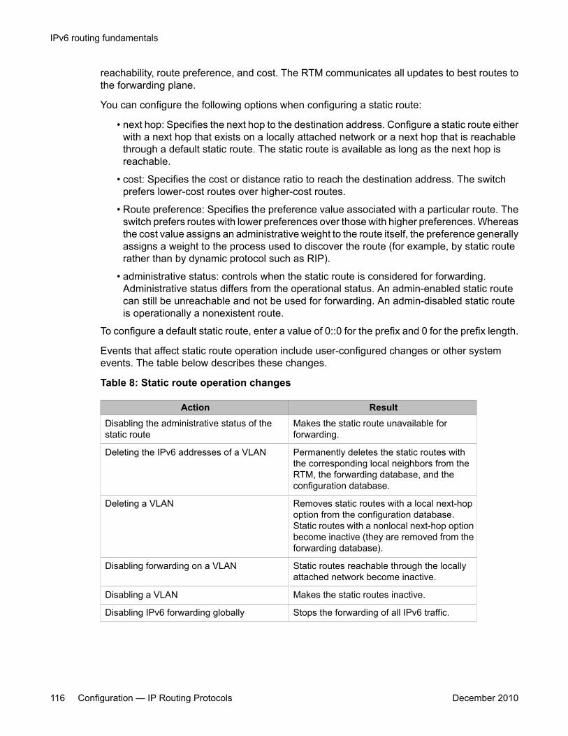
reachability, route preference, and cost. The RTM communicates all updates to best routes tothe forwarding plane.
You can configure the following options when configuring a static route:
• next hop: Specifies the next hop to the destination address. Configure a static route eitherwith a next hop that exists on a locally attached network or a next hop that is reachablethrough a default static route. The static route is available as long as the next hop isreachable.
• cost: Specifies the cost or distance ratio to reach the destination address. The switchprefers lower-cost routes over higher-cost routes.
• Route preference: Specifies the preference value associated with a particular route. Theswitch prefers routes with lower preferences over those with higher preferences. Whereasthe cost value assigns an administrative weight to the route itself, the preference generallyassigns a weight to the process used to discover the route (for example, by static routerather than by dynamic protocol such as RIP).
• administrative status: controls when the static route is considered for forwarding.Administrative status differs from the operational status. An admin-enabled static routecan still be unreachable and not be used for forwarding. An admin-disabled static routeis operationally a nonexistent route.
To configure a default static route, enter a value of 0::0 for the prefix and 0 for the prefix length.
Events that affect static route operation include user-configured changes or other systemevents. The table below describes these changes.
Table 8: Static route operation changes
Action ResultDisabling the administrative status of thestatic route
Makes the static route unavailable forforwarding.
Deleting the IPv6 addresses of a VLAN Permanently deletes the static routes withthe corresponding local neighbors from theRTM, the forwarding database, and theconfiguration database.
Deleting a VLAN Removes static routes with a local next-hopoption from the configuration database.Static routes with a nonlocal next-hop optionbecome inactive (they are removed from theforwarding database).
Disabling forwarding on a VLAN Static routes reachable through the locallyattached network become inactive.
Disabling a VLAN Makes the static routes inactive.
Disabling IPv6 forwarding globally Stops the forwarding of all IPv6 traffic.
IPv6 routing fundamentals
116 Configuration — IP Routing Protocols December 2010
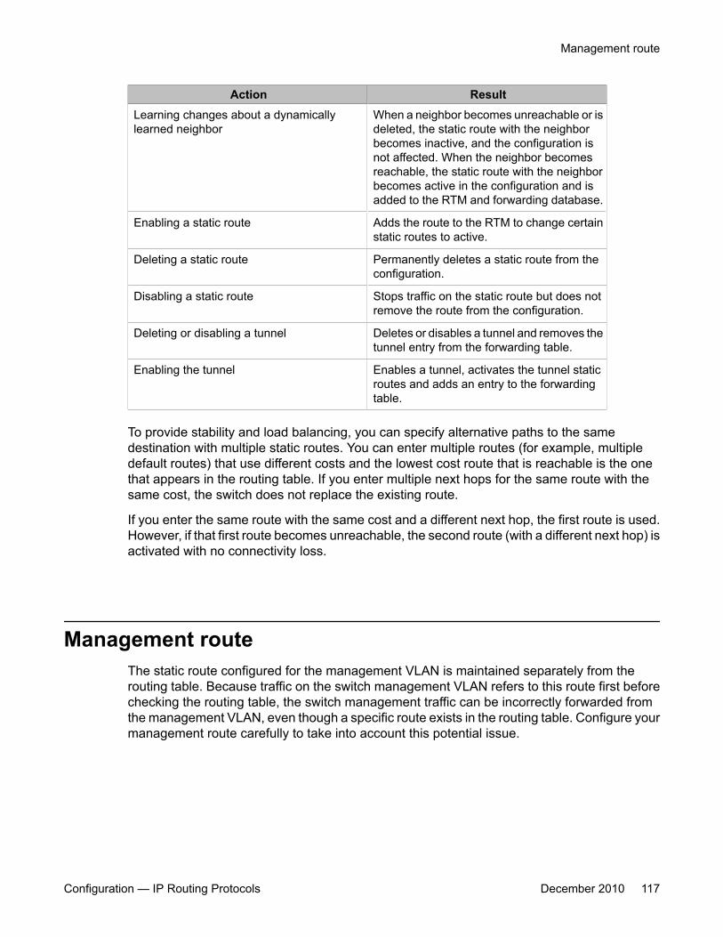
Action ResultLearning changes about a dynamicallylearned neighbor
When a neighbor becomes unreachable or isdeleted, the static route with the neighborbecomes inactive, and the configuration isnot affected. When the neighbor becomesreachable, the static route with the neighborbecomes active in the configuration and isadded to the RTM and forwarding database.
Enabling a static route Adds the route to the RTM to change certainstatic routes to active.
Deleting a static route Permanently deletes a static route from theconfiguration.
Disabling a static route Stops traffic on the static route but does notremove the route from the configuration.
Deleting or disabling a tunnel Deletes or disables a tunnel and removes thetunnel entry from the forwarding table.
Enabling the tunnel Enables a tunnel, activates the tunnel staticroutes and adds an entry to the forwardingtable.
To provide stability and load balancing, you can specify alternative paths to the samedestination with multiple static routes. You can enter multiple routes (for example, multipledefault routes) that use different costs and the lowest cost route that is reachable is the onethat appears in the routing table. If you enter multiple next hops for the same route with thesame cost, the switch does not replace the existing route.
If you enter the same route with the same cost and a different next hop, the first route is used.However, if that first route becomes unreachable, the second route (with a different next hop) isactivated with no connectivity loss.
Management routeThe static route configured for the management VLAN is maintained separately from therouting table. Because traffic on the switch management VLAN refers to this route first beforechecking the routing table, the switch management traffic can be incorrectly forwarded fromthe management VLAN, even though a specific route exists in the routing table. Configure yourmanagement route carefully to take into account this potential issue.
Management route
Configuration — IP Routing Protocols December 2010 117
IPv6 DHCP RelayIPv6 DHCP Relay for the Ethernet Routing Switch 5000 Series switches allows the routingswitch to act as an IPv6 DHCP (or DHCPv6) relay agent, as described in RFC 3315, DynamicHost Configuration Protocol for IPv6 (DHCPv6).
A DHCPv6 relay agent is used to relay messages between a DHCPv6 client and a DHCPv6server connected to different VLANs.
DHCP for IPv6 enables DHCP servers to pass configuration parameters such as IPv6 networkaddresses to IPv6 nodes. DHCP supports automatic allocation of reusable network addressesand of additional configuration parameters.
In basic DHCP operation, a client locates and communicates with a DHCP server using areserved, link-scoped multicast address. For this to be possible, the client and the server haveto be connected to the same link.
To request the assignment of one or more IPv6 addresses, a client first locates a DHCP serverand then requests the assignment of addresses and other configuration information from theserver. The client sends a Solicit message to the All_DHCP_Relay_Agents_and_Servers(FF02::1:2) multicast address to find available DHCP servers. Any server that can meet therequirements from the client responds with an Advertise message. The client then choosesone of the servers and sends a Request message to the server asking for confirmedassignment of addresses and other configuration information. The server responds with aReply message that contains the confirmed addresses and configuration.
IPv6 DHCP clients use link-local addresses to send and receive DHCP messages.
However, in some situations, for ease of management, economy or scalability, it can bedesirable to allow a DHCP client to communicate with a DHCP server that is not connected tothe same link. The DHCP relay agent makes this possible, relaying the messages betweenthe client and the remote server.
To allow a DHCP client to send a message to a DHCP server that is not attached to the samelink, you must configure a DHCP relay agent on the client link to relay messages between theclient and server. The operation of the relay agent is transparent to the client.
A relay agent relays messages from clients and from other relay agents.
Related topics:Remote ID on page 118
Remote IDIPv6 DHCP Relay supports the Remote ID parameter (RFC 4649). When you enable RemoteID on the switch, the relay agent adds information about the client to DHCPv6 messages beforerelaying the messages to the DHCP server. The server can use the supplied information in the
IPv6 routing fundamentals
118 Configuration — IP Routing Protocols December 2010
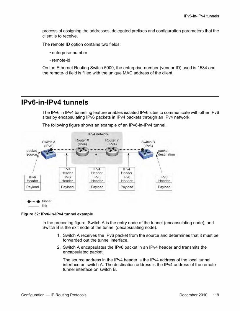
process of assigning the addresses, delegated prefixes and configuration parameters that theclient is to receive.
The remote ID option contains two fields:
• enterprise-number
• remote-id
On the Ethernet Routing Switch 5000, the enterprise-number (vendor ID) used is 1584 andthe remote-id field is filled with the unique MAC address of the client.
IPv6-in-IPv4 tunnelsThe IPv6 in IPv4 tunneling feature enables isolated IPv6 sites to communicate with other IPv6sites by encapsulating IPv6 packets in IPv4 packets through an IPv4 network.
The following figure shows an example of an IPv6-in-IPv4 tunnel.
Figure 32: IPv6-in-IPv4 tunnel example
In the preceding figure, Switch A is the entry node of the tunnel (encapsulating node), andSwitch B is the exit node of the tunnel (decapsulating node).
1. Switch A receives the IPv6 packet from the source and determines that it must beforwarded out the tunnel interface.
2. Switch A encapsulates the IPv6 packet in an IPv4 header and transmits theencapsulated packet.
The source address in the IPv4 header is the IPv4 address of the local tunnelinterface on switch A. The destination address is the IPv4 address of the remotetunnel interface on switch B.
IPv6-in-IPv4 tunnels
Configuration — IP Routing Protocols December 2010 119
3. Using the IPv4 header, the intermediate IPv4 routers forward the encapsulatedpacket through the IPv4 network to switch B.
4. Switch B receives the IPv4 packet, removes the outer IPv4 header, and thenprocesses the decapsulated IPv6 packet.
The Ethernet Routing Switch 5000 Series supports manually configured tunnels. To enablethe tunnel, you must manually specify the IPv4 addresses of the local and remote endpointsof the tunnel.
Related topics:Tunneling limitations on page 120
Tunneling limitationsThe following limitations apply to IPv6-in-IPv4 tunnels:
• Routing of data packets on these configured tunnels is not supported; that is, onlyapplications originating or terminating on the Ethernet Routing Switch 5000 Series canuse these tunnels.
• The maximum number of supported tunnels is four.
• Dynamic IPv6 routing protocols are not supported on tunnel interfaces.
• IPv4 path MTU discovery is not supported for data on tunnels.
• IPv4 fragmentation and reassembly is not supported over tunnels.
• IPv4 ICMP errors are not translated to IPv6 ICMP errors.
• IPv6 tunneling is not supported in Layer 2 mode.
• When the management VLAN IP is configured as a tunnel end point, tunnel functionality isnot supported after a stack transition (from stack to switch or switch to stack) becausethe IPv4 source address in the stack and switch are different. In this case, you mustreconfigure the tunnel source to the new management VLAN IP address.
• All ACLI commands for IPv6 can only be executed on the base unit of a stack.
• Stacking support is provided only on pure 5500 or 5600 stacks or on Hybrid stacks.
IPv6 routing fundamentals
120 Configuration — IP Routing Protocols December 2010
Chapter 6: IP routing configuration usingACLI
This chapter describes the procedures you can use to configure routable VLANs using the ACLI.
The Avaya Ethernet Routing Switch 5000 Series are Layer 3 (L3) switches. This means that a regularLayer 2 VLAN becomes a routable Layer 3 VLAN if an IP address and MAC address are attached to theVLAN. When routing is enabled in Layer 3 mode, every Layer 3 VLAN is capable of routing as well ascarrying the management traffic. You can use any Layer 3 VLAN instead of the Management VLAN tomanage the switch.
For more information on creating and configuring VLANs, see Configuration — VLANs, Spanning Tree,and Link Aggregation (NN47200-502).
IP routing configuration proceduresTo configure inter-VLAN routing on the switch, perform the following steps:
1. Enable IP routing globally.
2. Assign an IP address to a specific VLAN or brouter port.
Routing is automatically enabled on the VLAN or brouter port when you assign anIP address to it.
In the above procedure, you are not required to enable IP routing as the first step. All IP routingparameters can be configured on the Avaya Ethernet Routing Switch 5000 Series beforerouting is actually enabled on the switch.
IP routing configuration navigation• Configuring global IP routing status on page 122
• Displaying global IP routing status on page 122
• Configuring an IP address for a VLAN on page 123
• Configuring IP routing status on a VLAN on page 123
• Configuring a secondary IP address for a VLAN on page 124
Configuration — IP Routing Protocols December 2010 121

• Displaying the IP address configuration and routing status for a VLAN on page 125
• Displaying IP routes on page 126
• Performing a traceroute on page 128
• Entering Router Configuration mode on page 129
Configuring global IP routing statusUse this procedure to enable and disable global routing at the switch level. By default, routing isdisabled.
Procedure steps
To configure the status of IP routing on the switch, enter the following from the GlobalConfiguration mode:
[no] ip routing
Variable definitionsThe following table describes the command variables.
Variable Valueno Disables IP routing on the switch.
Displaying global IP routing statusUse this command to display the status of IP blocking on the switch.
Procedure steps
To display the status of IP blocking on the switch, enter the following from the UserEXEC mode:
IP routing configuration using ACLI
122 Configuration — IP Routing Protocols December 2010
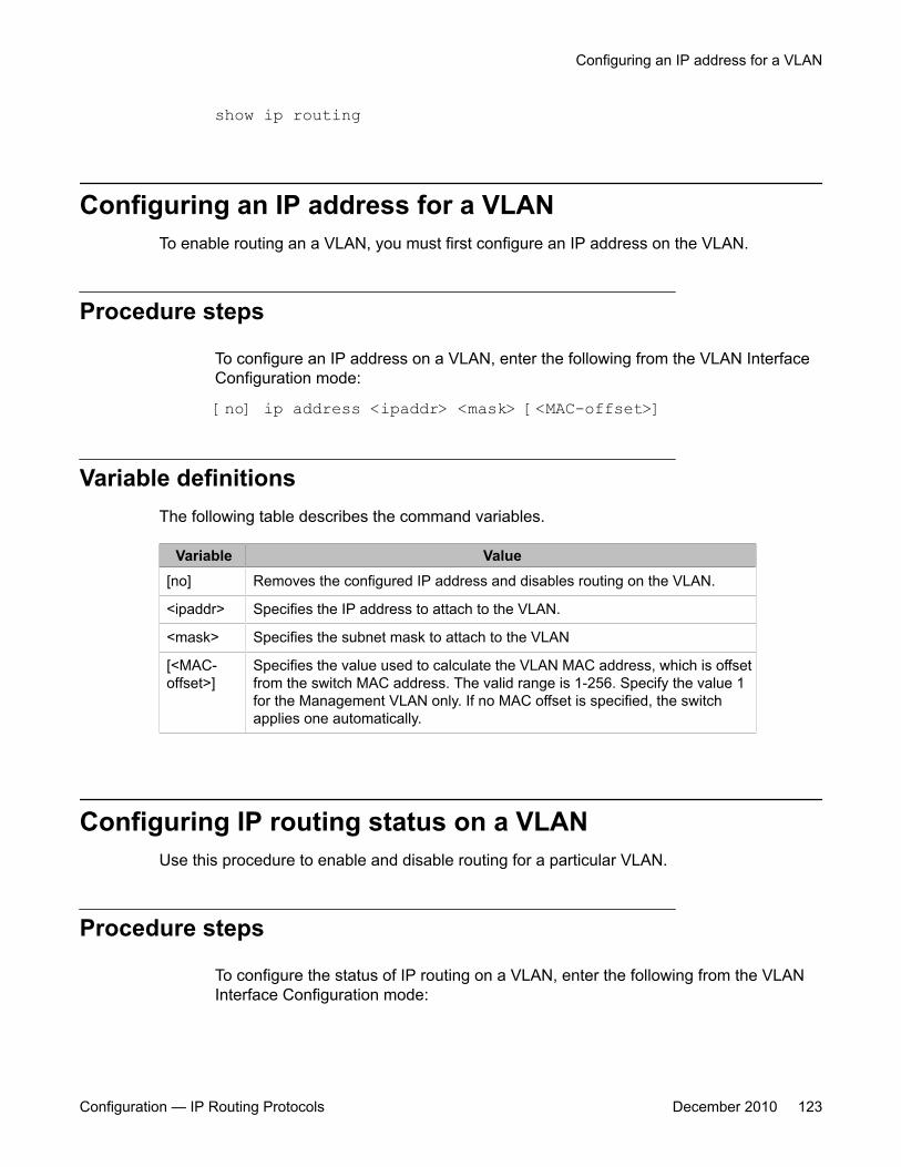
show ip routing
Configuring an IP address for a VLANTo enable routing an a VLAN, you must first configure an IP address on the VLAN.
Procedure steps
To configure an IP address on a VLAN, enter the following from the VLAN InterfaceConfiguration mode:
[no] ip address <ipaddr> <mask> [<MAC-offset>]
Variable definitionsThe following table describes the command variables.
Variable Value[no] Removes the configured IP address and disables routing on the VLAN.
<ipaddr> Specifies the IP address to attach to the VLAN.
<mask> Specifies the subnet mask to attach to the VLAN
[<MAC-offset>]
Specifies the value used to calculate the VLAN MAC address, which is offsetfrom the switch MAC address. The valid range is 1-256. Specify the value 1for the Management VLAN only. If no MAC offset is specified, the switchapplies one automatically.
Configuring IP routing status on a VLANUse this procedure to enable and disable routing for a particular VLAN.
Procedure steps
To configure the status of IP routing on a VLAN, enter the following from the VLANInterface Configuration mode:
Configuring an IP address for a VLAN
Configuration — IP Routing Protocols December 2010 123

[default] [no] ip routing
Variable definitionsThe following table describes the command variables.
Variable Valuedefault Disables IP routing on the VLAN.
no Disables IP routing on the VLAN.
Configuring a secondary IP address for a VLANUse this procedure to configure a secondary IP interface to a VLAN (also known asmultinetting). You can have a maximum of eight secondary IP addresses for every primaryaddress, and you must configure the primary address before configuring any secondaryaddresses.
Primary and secondary interfaces must reside on different subnets.
To remove a primary IP address from a VLAN, you must first remove all secondary addressesfrom the VLAN.
Prerequisites
Configure a primary IP address on the VLAN.
Procedure steps
To configure the secondary IP interface on the VLAN, enter the following from the VLANInterface Configuration mode.
[no] ip address <ip address> <mask> [<mac offset>] secondary
Variable definitionsThe following table describes the command variables.
IP routing configuration using ACLI
124 Configuration — IP Routing Protocols December 2010
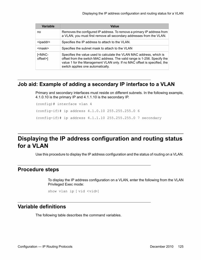
Variable Valueno Removes the configured IP address. To remove a primary IP address from
a VLAN, you must first remove all secondary addresses from the VLAN.
<ipaddr> Specifies the IP address to attach to the VLAN.
<mask> Specifies the subnet mask to attach to the VLAN
[<MAC-offset>]
Specifies the value used to calculate the VLAN MAC address, which isoffset from the switch MAC address. The valid range is 1-256. Specify thevalue 1 for the Management VLAN only. If no MAC offset is specified, theswitch applies one automatically.
Job aid: Example of adding a secondary IP interface to a VLANPrimary and secondary interfaces must reside on different subnets. In the following example,4.1.0.10 is the primary IP and 4.1.1.10 is the secondary IP.
(config)# interface vlan 4(config-if)# ip address 4.1.0.10 255.255.255.0 6(config-if)# ip address 4.1.1.10 255.255.255.0 7 secondary
Displaying the IP address configuration and routing statusfor a VLAN
Use this procedure to display the IP address configuration and the status of routing on a VLAN.
Procedure steps
To display the IP address configuration on a VLAN, enter the following from the VLANPrivileged Exec mode:
show vlan ip [vid <vid>]
Variable definitionsThe following table describes the command variables.
Displaying the IP address configuration and routing status for a VLAN
Configuration — IP Routing Protocols December 2010 125
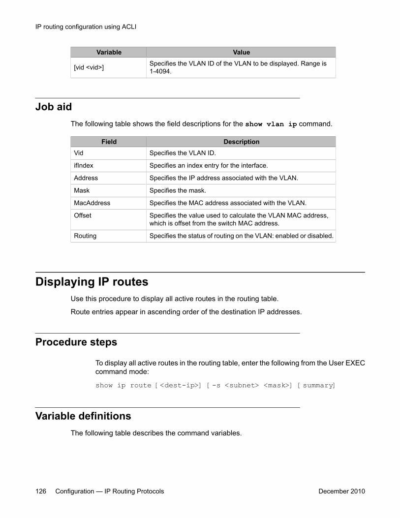
Variable Value
[vid <vid>] Specifies the VLAN ID of the VLAN to be displayed. Range is1-4094.
Job aidThe following table shows the field descriptions for the show vlan ip command.
Field DescriptionVid Specifies the VLAN ID.
ifIndex Specifies an index entry for the interface.
Address Specifies the IP address associated with the VLAN.
Mask Specifies the mask.
MacAddress Specifies the MAC address associated with the VLAN.
Offset Specifies the value used to calculate the VLAN MAC address,which is offset from the switch MAC address.
Routing Specifies the status of routing on the VLAN: enabled or disabled.
Displaying IP routesUse this procedure to display all active routes in the routing table.
Route entries appear in ascending order of the destination IP addresses.
Procedure steps
To display all active routes in the routing table, enter the following from the User EXECcommand mode:
show ip route [<dest-ip>] [-s <subnet> <mask>] [summary]
Variable definitionsThe following table describes the command variables.
IP routing configuration using ACLI
126 Configuration — IP Routing Protocols December 2010
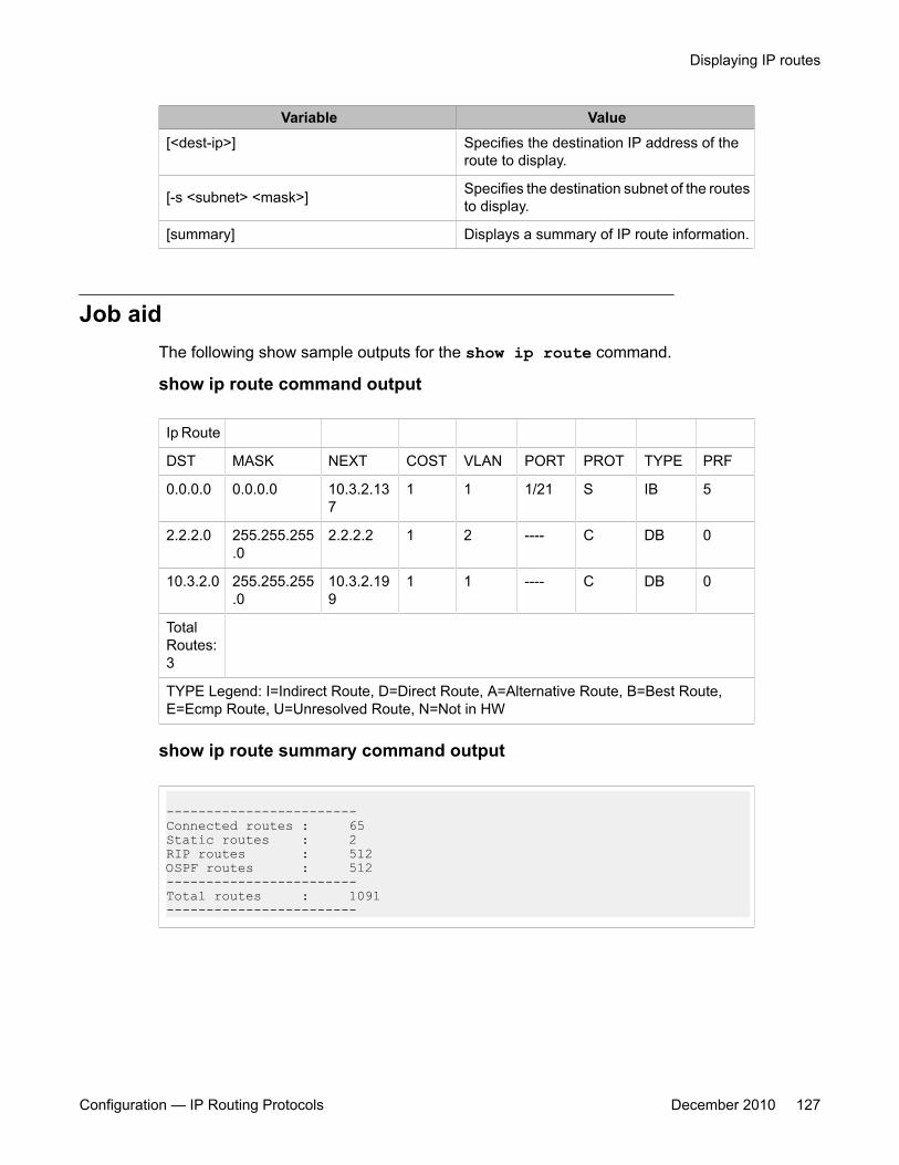
Variable Value[<dest-ip>] Specifies the destination IP address of the
route to display.
[-s <subnet> <mask>] Specifies the destination subnet of the routesto display.
[summary] Displays a summary of IP route information.
Job aidThe following show sample outputs for the show ip route command.
show ip route command output
Ip Route
DST MASK NEXT COST VLAN PORT PROT TYPE PRF
0.0.0.0 0.0.0.0 10.3.2.137
1 1 1/21 S IB 5
2.2.2.0 255.255.255.0
2.2.2.2 1 2 ---- C DB 0
10.3.2.0 255.255.255.0
10.3.2.199
1 1 ---- C DB 0
TotalRoutes:3
TYPE Legend: I=Indirect Route, D=Direct Route, A=Alternative Route, B=Best Route,E=Ecmp Route, U=Unresolved Route, N=Not in HW
show ip route summary command output
------------------------Connected routes : 65Static routes : 2RIP routes : 512OSPF routes : 512------------------------Total routes : 1091------------------------
Displaying IP routes
Configuration — IP Routing Protocols December 2010 127
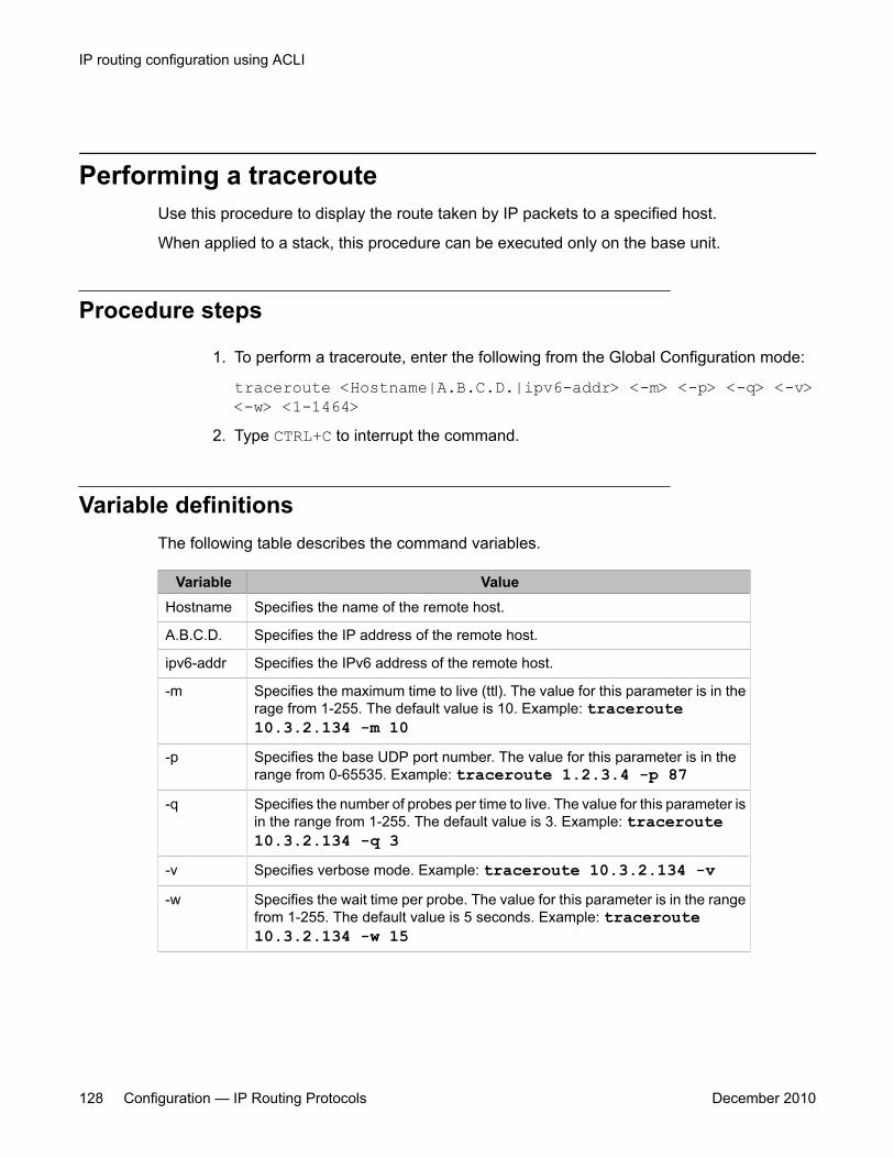
Performing a tracerouteUse this procedure to display the route taken by IP packets to a specified host.
When applied to a stack, this procedure can be executed only on the base unit.
Procedure steps
1. To perform a traceroute, enter the following from the Global Configuration mode:
traceroute <Hostname|A.B.C.D.|ipv6-addr> <-m> <-p> <-q> <-v><-w> <1-1464>
2. Type CTRL+C to interrupt the command.
Variable definitionsThe following table describes the command variables.
Variable ValueHostname Specifies the name of the remote host.
A.B.C.D. Specifies the IP address of the remote host.
ipv6-addr Specifies the IPv6 address of the remote host.
-m Specifies the maximum time to live (ttl). The value for this parameter is in therage from 1-255. The default value is 10. Example: traceroute10.3.2.134 -m 10
-p Specifies the base UDP port number. The value for this parameter is in therange from 0-65535. Example: traceroute 1.2.3.4 -p 87
-q Specifies the number of probes per time to live. The value for this parameter isin the range from 1-255. The default value is 3. Example: traceroute10.3.2.134 -q 3
-v Specifies verbose mode. Example: traceroute 10.3.2.134 -v-w Specifies the wait time per probe. The value for this parameter is in the range
from 1-255. The default value is 5 seconds. Example: traceroute10.3.2.134 -w 15
IP routing configuration using ACLI
128 Configuration — IP Routing Protocols December 2010
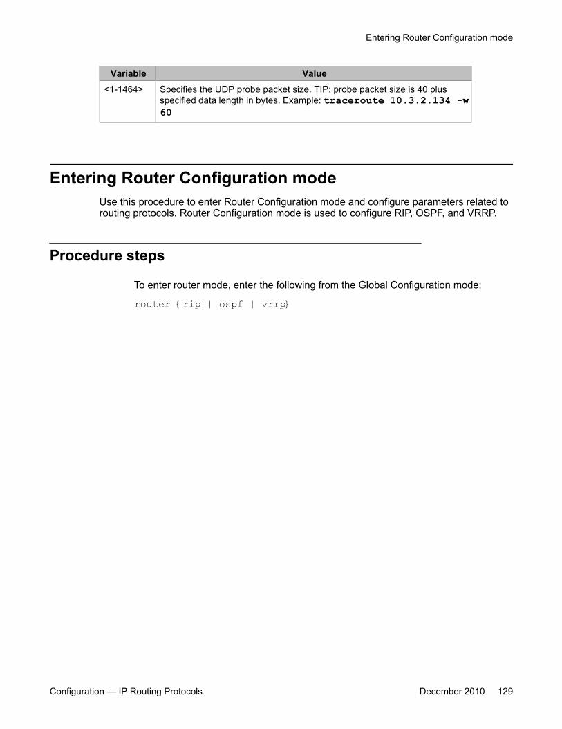
Variable Value<1-1464> Specifies the UDP probe packet size. TIP: probe packet size is 40 plus
specified data length in bytes. Example: traceroute 10.3.2.134 -w60
Entering Router Configuration modeUse this procedure to enter Router Configuration mode and configure parameters related torouting protocols. Router Configuration mode is used to configure RIP, OSPF, and VRRP.
Procedure steps
To enter router mode, enter the following from the Global Configuration mode:
router {rip | ospf | vrrp}
Entering Router Configuration mode
Configuration — IP Routing Protocols December 2010 129

IP routing configuration using ACLI
130 Configuration — IP Routing Protocols December 2010

Chapter 7: Brouter port configuration usingACLI
A brouter port is a single-port VLAN that can route IP packets as well as bridge all non-routable traffic.The following section describes the ACLI commands used to configure and manage brouter ports on theAvaya Ethernet Routing Switch 5000 Series .
Brouter port configuration navigation• Configuring a brouter port on page 131
• Displaying the brouter port configuration on page 132
Configuring a brouter portUse this procedure to create and manage a brouter port on the switch.
Procedure steps
To configure a brouter port, enter the following from the FastEthernet InterfaceConfiguration mode:
brouter [port <brouter_port>] vlan <vid> subnet <ip_address/mask> [routing enable]
Variable definitionsThe following table describes the command variables.
Variable Value[no] Removes the brouter configuration from the switch
Configuration — IP Routing Protocols December 2010 131
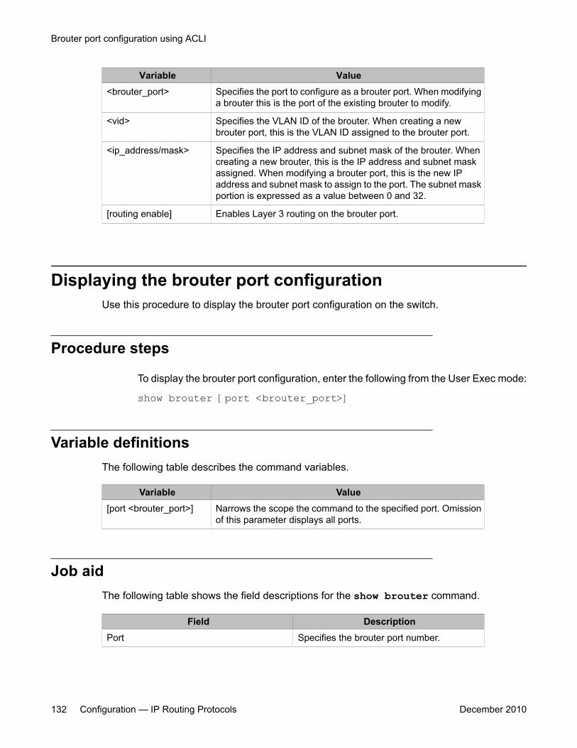
Variable Value<brouter_port> Specifies the port to configure as a brouter port. When modifying
a brouter this is the port of the existing brouter to modify.
<vid> Specifies the VLAN ID of the brouter. When creating a newbrouter port, this is the VLAN ID assigned to the brouter port.
<ip_address/mask> Specifies the IP address and subnet mask of the brouter. Whencreating a new brouter, this is the IP address and subnet maskassigned. When modifying a brouter port, this is the new IPaddress and subnet mask to assign to the port. The subnet maskportion is expressed as a value between 0 and 32.
[routing enable] Enables Layer 3 routing on the brouter port.
Displaying the brouter port configurationUse this procedure to display the brouter port configuration on the switch.
Procedure steps
To display the brouter port configuration, enter the following from the User Exec mode:
show brouter [port <brouter_port>]
Variable definitionsThe following table describes the command variables.
Variable Value[port <brouter_port>] Narrows the scope the command to the specified port. Omission
of this parameter displays all ports.
Job aidThe following table shows the field descriptions for the show brouter command.
Field DescriptionPort Specifies the brouter port number.
Brouter port configuration using ACLI
132 Configuration — IP Routing Protocols December 2010

Field DescriptionBrouter VID Specifies the brouter VLAN ID.
IP/Mask Specifies the IP address and subnet mask ofthe brouter.
IP Routing Specifies whether IP routing is enabled ordisabled on the brouter.
Displaying the brouter port configuration
Configuration — IP Routing Protocols December 2010 133

Brouter port configuration using ACLI
134 Configuration — IP Routing Protocols December 2010
Chapter 8: Static route configuration usingACLI
This chapter describes the procedures you can use to configure static routes using the ACLI.
Static route configuration navigation• Configuring a static route on page 135
• Displaying static routes on page 136
• Configuring a management route on page 137
• Displaying the management routes on page 138
Configuring a static routeUse this procedure to configure a static route. Create static routes to manually configure a pathto destination IP address prefixes.
Prerequisites
• Enable IP routing globally.
• Enable IP routing and configure an IP address on the VLANs to be routed.
Procedure steps
To configure a static route, enter the following from the Global Configuration commandmode:
Configuration — IP Routing Protocols December 2010 135
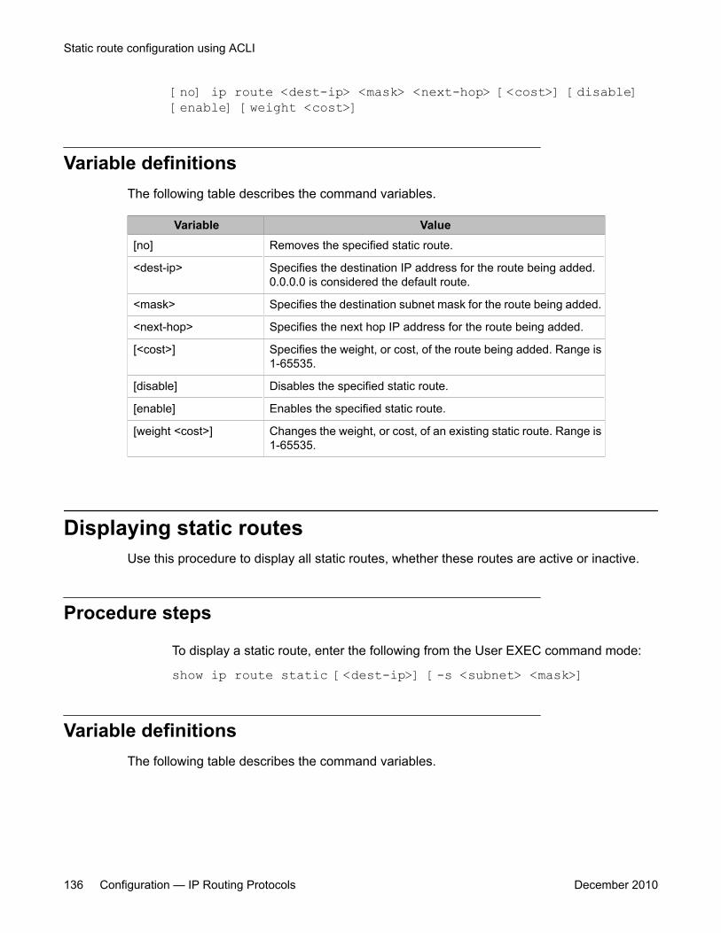
[no] ip route <dest-ip> <mask> <next-hop> [<cost>] [disable][enable] [weight <cost>]
Variable definitionsThe following table describes the command variables.
Variable Value[no] Removes the specified static route.
<dest-ip> Specifies the destination IP address for the route being added.0.0.0.0 is considered the default route.
<mask> Specifies the destination subnet mask for the route being added.
<next-hop> Specifies the next hop IP address for the route being added.
[<cost>] Specifies the weight, or cost, of the route being added. Range is1-65535.
[disable] Disables the specified static route.
[enable] Enables the specified static route.
[weight <cost>] Changes the weight, or cost, of an existing static route. Range is1-65535.
Displaying static routesUse this procedure to display all static routes, whether these routes are active or inactive.
Procedure steps
To display a static route, enter the following from the User EXEC command mode:
show ip route static [<dest-ip>] [-s <subnet> <mask>]
Variable definitionsThe following table describes the command variables.
Static route configuration using ACLI
136 Configuration — IP Routing Protocols December 2010
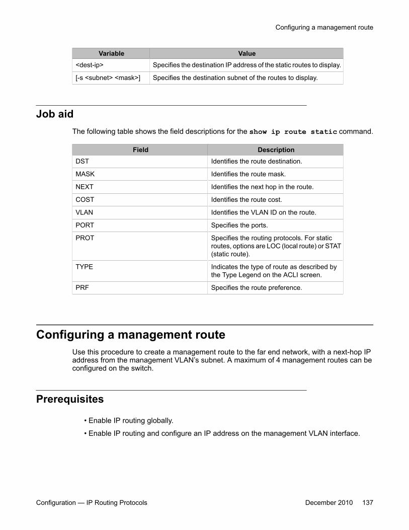
Variable Value<dest-ip> Specifies the destination IP address of the static routes to display.
[-s <subnet> <mask>] Specifies the destination subnet of the routes to display.
Job aidThe following table shows the field descriptions for the show ip route static command.
Field DescriptionDST Identifies the route destination.
MASK Identifies the route mask.
NEXT Identifies the next hop in the route.
COST Identifies the route cost.
VLAN Identifies the VLAN ID on the route.
PORT Specifies the ports.
PROT Specifies the routing protocols. For staticroutes, options are LOC (local route) or STAT(static route).
TYPE Indicates the type of route as described bythe Type Legend on the ACLI screen.
PRF Specifies the route preference.
Configuring a management routeUse this procedure to create a management route to the far end network, with a next-hop IPaddress from the management VLAN’s subnet. A maximum of 4 management routes can beconfigured on the switch.
Prerequisites
• Enable IP routing globally.
• Enable IP routing and configure an IP address on the management VLAN interface.
Configuring a management route
Configuration — IP Routing Protocols December 2010 137
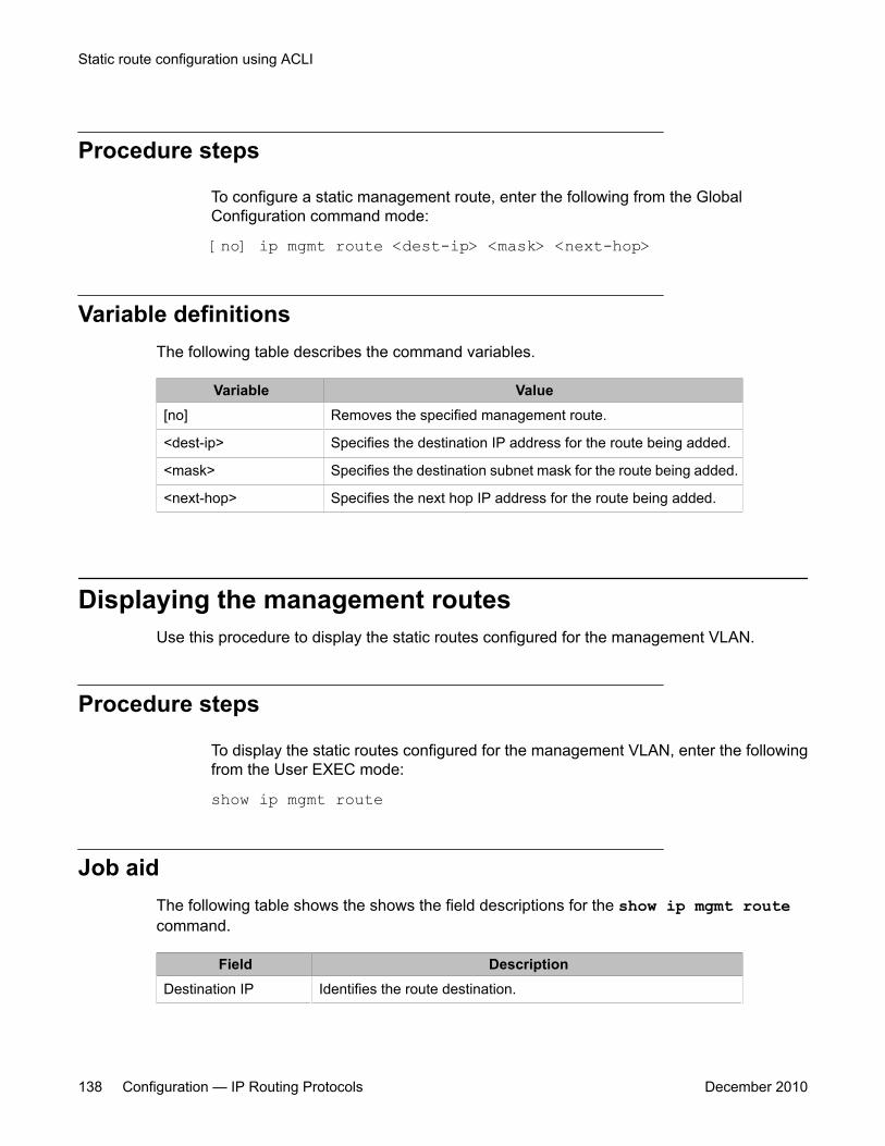
Procedure steps
To configure a static management route, enter the following from the GlobalConfiguration command mode:
[no] ip mgmt route <dest-ip> <mask> <next-hop>
Variable definitionsThe following table describes the command variables.
Variable Value[no] Removes the specified management route.
<dest-ip> Specifies the destination IP address for the route being added.
<mask> Specifies the destination subnet mask for the route being added.
<next-hop> Specifies the next hop IP address for the route being added.
Displaying the management routesUse this procedure to display the static routes configured for the management VLAN.
Procedure steps
To display the static routes configured for the management VLAN, enter the followingfrom the User EXEC mode:
show ip mgmt route
Job aidThe following table shows the shows the field descriptions for the show ip mgmt routecommand.
Field DescriptionDestination IP Identifies the route destination.
Static route configuration using ACLI
138 Configuration — IP Routing Protocols December 2010
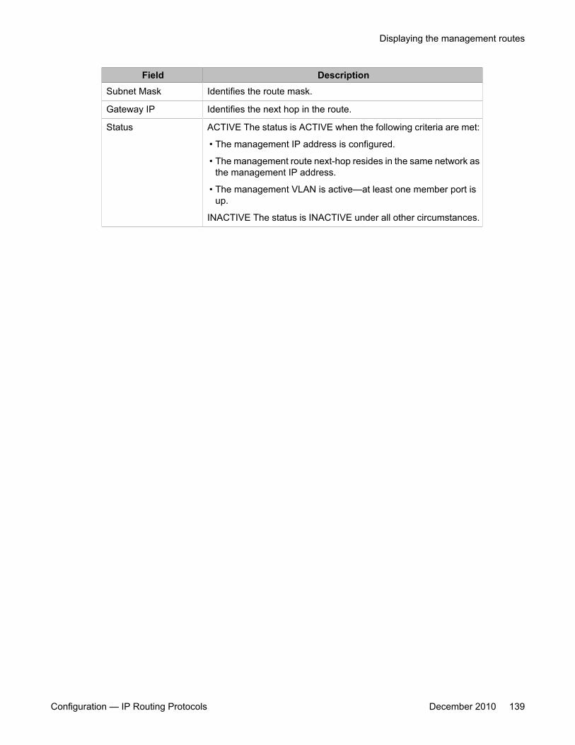
Field DescriptionSubnet Mask Identifies the route mask.
Gateway IP Identifies the next hop in the route.
Status ACTIVE The status is ACTIVE when the following criteria are met:
• The management IP address is configured.
• The management route next-hop resides in the same network asthe management IP address.
• The management VLAN is active—at least one member port isup.
INACTIVE The status is INACTIVE under all other circumstances.
Displaying the management routes
Configuration — IP Routing Protocols December 2010 139

Static route configuration using ACLI
140 Configuration — IP Routing Protocols December 2010

Chapter 9: OSPF configuration using ACLI
This chapter describes the procedures you can use to configure OSPF using ACLI.
The Open Shortest Path First (OSPF) Protocol is an Interior Gateway Protocol (IGP) that distributesrouting information between routers belonging to a single autonomous system (AS). Intended for use inlarge networks, OSPF is a link-state protocol which supports IP subnetting and the tagging of externally-derived routing information.
OSPF commands used during the configuration and management of VLANs in the Interface Configurationmode can be used to configure any VLAN regardless of the one used to log into the command mode.Insert the keyword vlan with the number of the VLAN to be configured after the command keywords ipospf. The current VLAN remains the one used to log into the Interface Configuration command mode afterthe command execution.
Prerequisites• Install the Advanced License.
• Enable IP routing globally on the switch.
• Assign an IP address to the VLAN that you want to enable with OSPF.
Routing is automatically enabled on the VLAN when you assign an IP address to it.
OSPF configuration navigation• Configuring the OSPF hardware mode on page 142
• Configuring the router ID on page 143
• Configuring global OSPF status on page 143
• Configuring global OSPF parameters on page 144
• Displaying global OSPF parameters on page 145
• Configuring OSPF area parameters on page 145
• Displaying OSPF area configuration on page 147
• Displaying OSPF area range information on page 147
Configuration — IP Routing Protocols December 2010 141
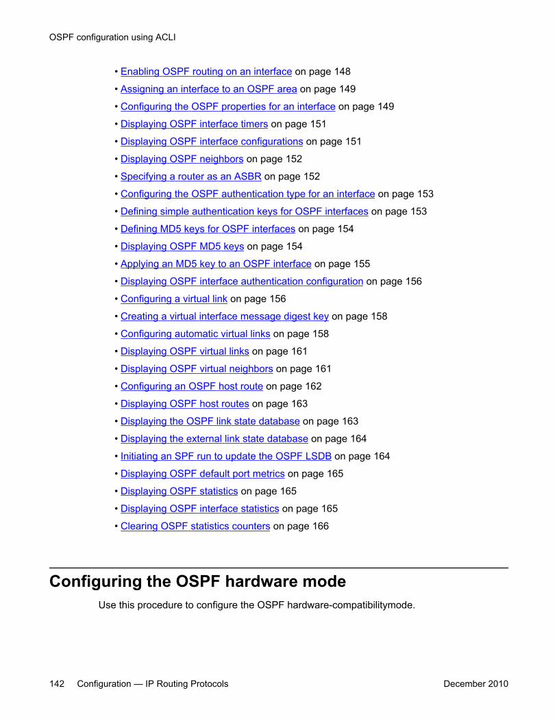
• Enabling OSPF routing on an interface on page 148
• Assigning an interface to an OSPF area on page 149
• Configuring the OSPF properties for an interface on page 149
• Displaying OSPF interface timers on page 151
• Displaying OSPF interface configurations on page 151
• Displaying OSPF neighbors on page 152
• Specifying a router as an ASBR on page 152
• Configuring the OSPF authentication type for an interface on page 153
• Defining simple authentication keys for OSPF interfaces on page 153
• Defining MD5 keys for OSPF interfaces on page 154
• Displaying OSPF MD5 keys on page 154
• Applying an MD5 key to an OSPF interface on page 155
• Displaying OSPF interface authentication configuration on page 156
• Configuring a virtual link on page 156
• Creating a virtual interface message digest key on page 158
• Configuring automatic virtual links on page 158
• Displaying OSPF virtual links on page 161
• Displaying OSPF virtual neighbors on page 161
• Configuring an OSPF host route on page 162
• Displaying OSPF host routes on page 163
• Displaying the OSPF link state database on page 163
• Displaying the external link state database on page 164
• Initiating an SPF run to update the OSPF LSDB on page 164
• Displaying OSPF default port metrics on page 165
• Displaying OSPF statistics on page 165
• Displaying OSPF interface statistics on page 165
• Clearing OSPF statistics counters on page 166
Configuring the OSPF hardware modeUse this procedure to configure the OSPF hardware-compatibilitymode.
OSPF configuration using ACLI
142 Configuration — IP Routing Protocols December 2010

Procedure steps
To configure the OSPF hardware-compatibility mode, enter the following from theGlobal Configuration command mode:
ip ospf op-mode {5510 | non-5510}
Configuring the router IDUse this procedure to configure the router ID, which is expressed in the form of an IP address.
Procedure steps
To configure the router ID, enter the following from the OSPF Router Configurationcommand mode:
[no] router-id <router_id>
Variable definitionsThe following table describes the command variables.
Variable Value[no] Resets the router ID to 0.0.0.0.
<router_id> Specifies the unique identifier for the router.
Configuring global OSPF statusUse this procedure to configure the status of OSPF globally on the switch.
By default, OSPF is disabled.
Configuring the router ID
Configuration — IP Routing Protocols December 2010 143
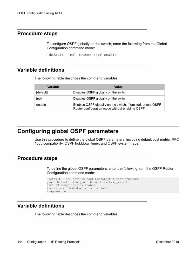
Procedure steps
To configure OSPF globally on the switch, enter the following from the GlobalConfiguration command mode:
[default] [no] router ospf enable
Variable definitionsThe following table describes the command variables.
Variable Value[default] Disables OSPF globally on the switch.
[no] Disables OSPF globally on the switch.
enable Enables OSPF globally on the switch. If omitted, enters OSPFRouter configuration mode without enabling OSPF.
Configuring global OSPF parametersUse this procedure to define the global OSPF parameters, including default cost metric, RFC1583 compatibility, OSPF holddown timer, and OSPF system traps.
Procedure steps
To define the global OSPF parameters, enter the following from the OSPF RouterConfiguration command mode:[default] [no] default-cost {ethernet | fast-ethernet |gig-ethernet | ten-gig-ethernet} <metric_value>rfc1583-compatibility enabletimers basic holddown <timer_value>trap enable
Variable definitionsThe following table describes the command variables.
OSPF configuration using ACLI
144 Configuration — IP Routing Protocols December 2010
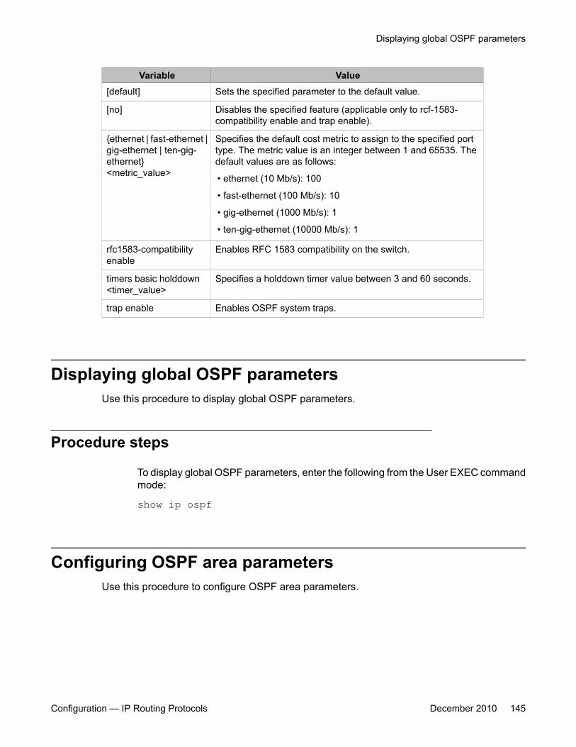
Variable Value[default] Sets the specified parameter to the default value.
[no] Disables the specified feature (applicable only to rcf-1583-compatibility enable and trap enable).
{ethernet | fast-ethernet |gig-ethernet | ten-gig-ethernet}<metric_value>
Specifies the default cost metric to assign to the specified porttype. The metric value is an integer between 1 and 65535. Thedefault values are as follows:
• ethernet (10 Mb/s): 100
• fast-ethernet (100 Mb/s): 10
• gig-ethernet (1000 Mb/s): 1
• ten-gig-ethernet (10000 Mb/s): 1
rfc1583-compatibilityenable
Enables RFC 1583 compatibility on the switch.
timers basic holddown<timer_value>
Specifies a holddown timer value between 3 and 60 seconds.
trap enable Enables OSPF system traps.
Displaying global OSPF parametersUse this procedure to display global OSPF parameters.
Procedure steps
To display global OSPF parameters, enter the following from the User EXEC commandmode:
show ip ospf
Configuring OSPF area parametersUse this procedure to configure OSPF area parameters.
Displaying global OSPF parameters
Configuration — IP Routing Protocols December 2010 145
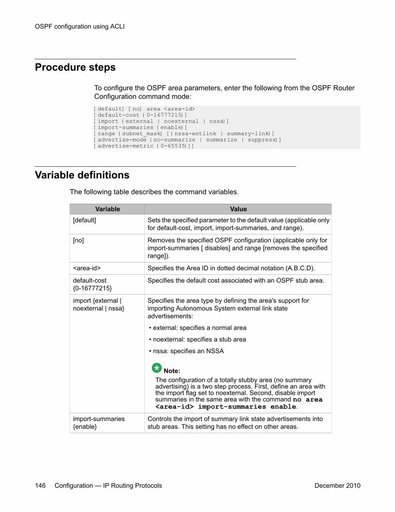
Procedure steps
To configure the OSPF area parameters, enter the following from the OSPF RouterConfiguration command mode:[default] [no] area <area-id>[default-cost {0-16777215}][import {external | noexternal | nssa}][import-summaries {enable}][range {subnet_mask} [{nssa-entlink | summary-link}][advertise-mode {no-summarize | summarize | suppress}][advertise-metric {0-65535}]]
Variable definitionsThe following table describes the command variables.
Variable Value[default] Sets the specified parameter to the default value (applicable only
for default-cost, import, import-summaries, and range).
[no] Removes the specified OSPF configuration (applicable only forimport-summaries [ disables] and range [removes the specifiedrange]).
<area-id> Specifies the Area ID in dotted decimal notation (A.B.C.D).
default-cost{0-16777215}
Specifies the default cost associated with an OSPF stub area.
import {external |noexternal | nssa}
Specifies the area type by defining the area's support forimporting Autonomous System external link stateadvertisements:
• external: specifies a normal area
• noexternal: specifies a stub area
• nssa: specifies an NSSA
Note:The configuration of a totally stubby area (no summaryadvertising) is a two step process. First, define an area withthe import flag set to noexternal. Second, disable importsummaries in the same area with the command no area<area-id> import-summaries enable.
import-summaries{enable}
Controls the import of summary link state advertisements intostub areas. This setting has no effect on other areas.
OSPF configuration using ACLI
146 Configuration — IP Routing Protocols December 2010
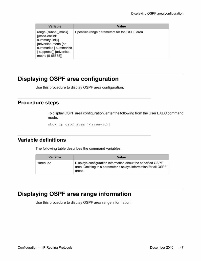
Variable Valuerange {subnet_mask}[{nssa-entlink |summary-link}][advertise-mode {no-summarize | summarize| suppress}] [advertise-metric {0-65535}]
Specifies range parameters for the OSPF area.
Displaying OSPF area configurationUse this procedure to display OSPF area configuration.
Procedure steps
To display OSPF area configuration, enter the following from the User EXEC commandmode:
show ip ospf area [<area-id>]
Variable definitionsThe following table describes the command variables.
Variable Value<area-id> Displays configuration information about the specified OSPF
area. Omitting this parameter displays information for all OSPFareas.
Displaying OSPF area range informationUse this procedure to display OSPF area range information.
Displaying OSPF area configuration
Configuration — IP Routing Protocols December 2010 147
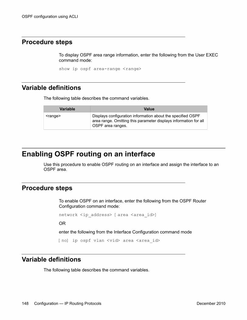
Procedure steps
To display OSPF area range information, enter the following from the User EXECcommand mode:
show ip ospf area-range <range>
Variable definitionsThe following table describes the command variables.
Variable Value<range> Displays configuration information about the specified OSPF
area range. Omitting this parameter displays information for allOSPF area ranges.
Enabling OSPF routing on an interfaceUse this procedure to enable OSPF routing on an interface and assign the interface to anOSPF area.
Procedure steps
To enable OSPF on an interface, enter the following from the OSPF RouterConfiguration command mode:
network <ip_address> [area <area_id>]OR
enter the following from the Interface Configuration command mode
[no] ip ospf vlan <vid> area <area_id>
Variable definitionsThe following table describes the command variables.
OSPF configuration using ACLI
148 Configuration — IP Routing Protocols December 2010
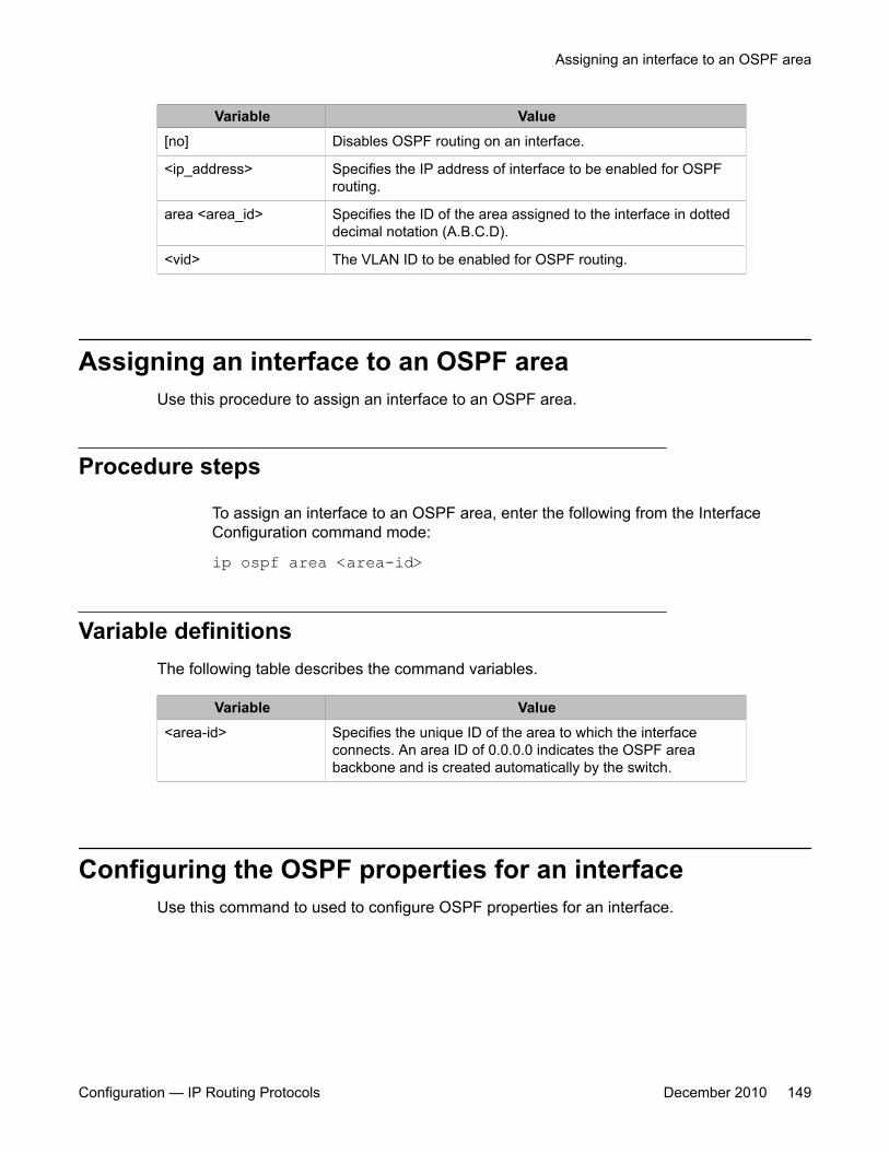
Variable Value[no] Disables OSPF routing on an interface.
<ip_address> Specifies the IP address of interface to be enabled for OSPFrouting.
area <area_id> Specifies the ID of the area assigned to the interface in dotteddecimal notation (A.B.C.D).
<vid> The VLAN ID to be enabled for OSPF routing.
Assigning an interface to an OSPF areaUse this procedure to assign an interface to an OSPF area.
Procedure steps
To assign an interface to an OSPF area, enter the following from the InterfaceConfiguration command mode:
ip ospf area <area-id>
Variable definitionsThe following table describes the command variables.
Variable Value<area-id> Specifies the unique ID of the area to which the interface
connects. An area ID of 0.0.0.0 indicates the OSPF areabackbone and is created automatically by the switch.
Configuring the OSPF properties for an interfaceUse this command to used to configure OSPF properties for an interface.
Assigning an interface to an OSPF area
Configuration — IP Routing Protocols December 2010 149
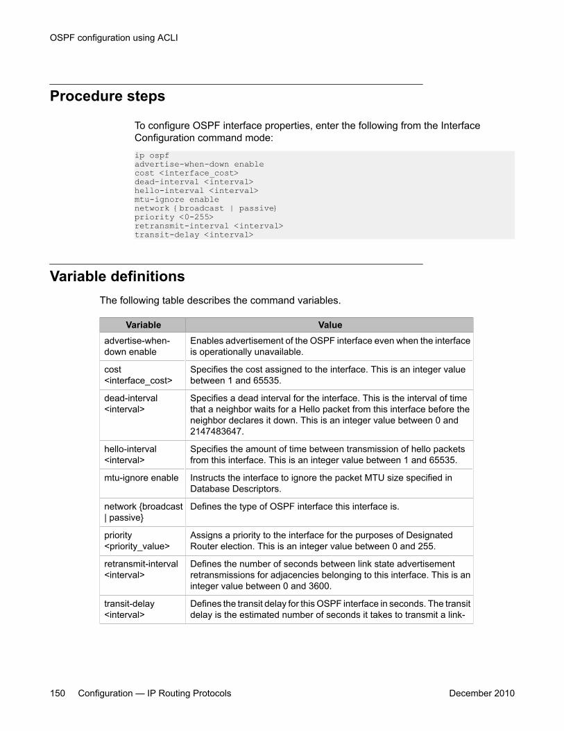
Procedure steps
To configure OSPF interface properties, enter the following from the InterfaceConfiguration command mode:ip ospfadvertise-when-down enablecost <interface_cost>dead-interval <interval>hello-interval <interval>mtu-ignore enablenetwork {broadcast | passive}priority <0-255>retransmit-interval <interval>transit-delay <interval>
Variable definitionsThe following table describes the command variables.
Variable Valueadvertise-when-down enable
Enables advertisement of the OSPF interface even when the interfaceis operationally unavailable.
cost<interface_cost>
Specifies the cost assigned to the interface. This is an integer valuebetween 1 and 65535.
dead-interval<interval>
Specifies a dead interval for the interface. This is the interval of timethat a neighbor waits for a Hello packet from this interface before theneighbor declares it down. This is an integer value between 0 and2147483647.
hello-interval<interval>
Specifies the amount of time between transmission of hello packetsfrom this interface. This is an integer value between 1 and 65535.
mtu-ignore enable Instructs the interface to ignore the packet MTU size specified inDatabase Descriptors.
network {broadcast| passive}
Defines the type of OSPF interface this interface is.
priority<priority_value>
Assigns a priority to the interface for the purposes of DesignatedRouter election. This is an integer value between 0 and 255.
retransmit-interval<interval>
Defines the number of seconds between link state advertisementretransmissions for adjacencies belonging to this interface. This is aninteger value between 0 and 3600.
transit-delay<interval>
Defines the transit delay for this OSPF interface in seconds. The transitdelay is the estimated number of seconds it takes to transmit a link-
OSPF configuration using ACLI
150 Configuration — IP Routing Protocols December 2010
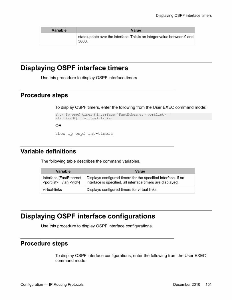
Variable Valuestate update over the interface. This is an integer value between 0 and3600.
Displaying OSPF interface timersUse this procedure to display OSPF interface timers
Procedure steps
To display OSPF timers, enter the following from the User EXEC command mode:show ip ospf timer {interface [FastEthernet <portlist> |vlan <vid>] | virtual-links}
OR
show ip ospf int-timers
Variable definitionsThe following table describes the command variables.
Variable Valueinterface [FastEthernet<portlist> | vlan <vid>]
Displays configured timers for the specified interface. If nointerface is specified, all interface timers are displayed.
virtual-links Displays configured timers for virtual links.
Displaying OSPF interface configurationsUse this procedure to display OSPF interface configurations.
Procedure steps
To display OSPF interface configurations, enter the following from the User EXECcommand mode:
Displaying OSPF interface timers
Configuration — IP Routing Protocols December 2010 151
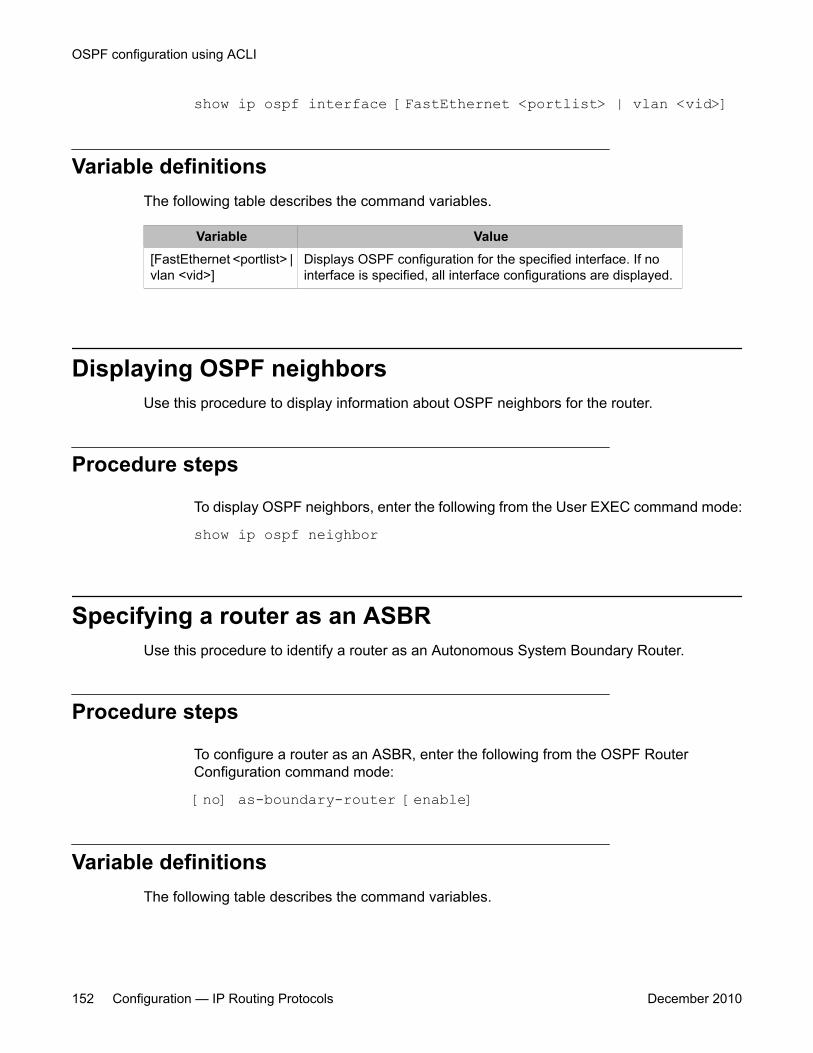
show ip ospf interface [FastEthernet <portlist> | vlan <vid>]
Variable definitionsThe following table describes the command variables.
Variable Value[FastEthernet <portlist> |vlan <vid>]
Displays OSPF configuration for the specified interface. If nointerface is specified, all interface configurations are displayed.
Displaying OSPF neighborsUse this procedure to display information about OSPF neighbors for the router.
Procedure steps
To display OSPF neighbors, enter the following from the User EXEC command mode:
show ip ospf neighbor
Specifying a router as an ASBRUse this procedure to identify a router as an Autonomous System Boundary Router.
Procedure steps
To configure a router as an ASBR, enter the following from the OSPF RouterConfiguration command mode:
[no] as-boundary-router [enable]
Variable definitionsThe following table describes the command variables.
OSPF configuration using ACLI
152 Configuration — IP Routing Protocols December 2010
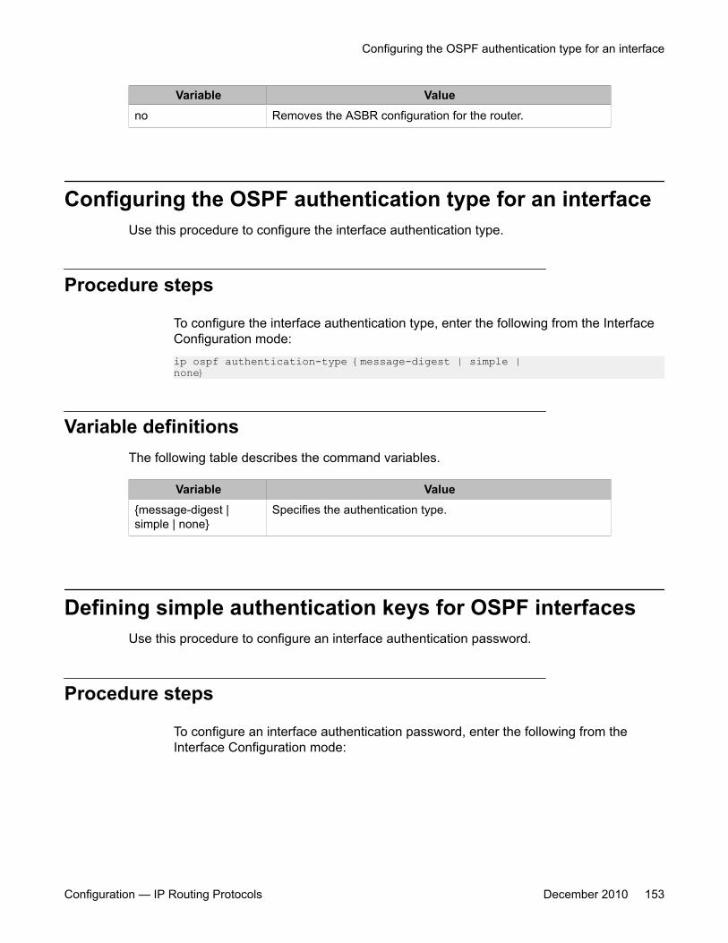
Variable Valueno Removes the ASBR configuration for the router.
Configuring the OSPF authentication type for an interfaceUse this procedure to configure the interface authentication type.
Procedure steps
To configure the interface authentication type, enter the following from the InterfaceConfiguration mode:ip ospf authentication-type {message-digest | simple |none}
Variable definitionsThe following table describes the command variables.
Variable Value{message-digest |simple | none}
Specifies the authentication type.
Defining simple authentication keys for OSPF interfacesUse this procedure to configure an interface authentication password.
Procedure steps
To configure an interface authentication password, enter the following from theInterface Configuration mode:
Configuring the OSPF authentication type for an interface
Configuration — IP Routing Protocols December 2010 153

ip opsf authentication-key <password>
Variable definitionsThe following table describes the command variables.
Variable Value<password> Specifies the password to be configured. This password can be
up to 8 characters in length.
Defining MD5 keys for OSPF interfacesUse this procedure to define the MD5 keys.
Procedure steps
To define an MD5 key, enter the following from the Interface Configuration commandmode:
ip ospf message-digest-key <key_number> md5 <key_value>
Variable definitionsThe following table describes the command variables.
Variable Value<key_number> Specifies an index value for the MD5 key being configured. This is
an integer value between 1 and 255.
<key_value> Specifies the value of the MD5 key. This is a string value of up to16 characters in length.
Displaying OSPF MD5 keysUse this procedure to display OSPF MD5 key configuration.
OSPF configuration using ACLI
154 Configuration — IP Routing Protocols December 2010

Procedure steps
To display OSPF MD5 keys, enter the following from the User EXEC command mode:show ip ospf authentication {interface [FastEthernet<portlist> | vlan <vid>] | virtual-links}
Variable definitionsThe following table describes the command variables.
Variable Valueinterface [FastEthernet<portlist> | vlan <vid>]
Displays configured MD5 authentication keys for the specifiedinterface. If no interface is specified, all interface MD5 keys aredisplayed.
virtual-links Displays configured MD5 authentication keys for virtual links.
Applying an MD5 key to an OSPF interfaceUse this procedure to specify the primary MD5 key (configured using the ip ospf message-digest-key command) to use for authentication in instances where interface authenticationuses an MD5 key.
Each OSPF interface supports up to 2 keys, identifiable by key ID, to facilitate a smooth keytransition during the rollover process. Only the selected primary key is used to encrypt theOSPF transmit packets.
Assuming that all routers already use the same key for authentication and a new key isrequired, the process of key change is as follows:
1. Add the second key to all routers. The routers will continue to send OSPF packetsencrypted with the old key.
2. Activate the second key on all routers by setting it as the primary key. Routers willsend OSPF packets encrypted with the new key while still accepting packets usingthe old key. This is necessary as some routers will not have activated the new key.
3. After all routers activate the new key, remove the old key.
Applying an MD5 key to an OSPF interface
Configuration — IP Routing Protocols December 2010 155
Procedure steps
To specify the primary MD5 key, enter the following from the Interface Configurationcommand mode:
ip ospf primary-md5-key <key_id>
Variable definitionsThe following table describes the command variables.
Variable Value<key_id> Specifies the index value for the MD5 key to apply. This is an
integer value between 1 and 255.
Displaying OSPF interface authentication configurationUse this procedure to display the authentication type and key applied to interfaces.
Procedure steps
To display OSPF authentication configuration for interfaces, enter the following fromthe User EXEC command mode:
show ip ospf int-auth
Configuring a virtual linkUse this procedure to create a virtual interface.
OSPF configuration using ACLI
156 Configuration — IP Routing Protocols December 2010
Procedure steps
To create a virtual interface, enter the following from the OSPF Router Configurationcommand mode:[no] area virtual-link <area-id> <nghbr-router-id>{[authentication-key <WORD>] [authentication-type{none|simple|message-digest}] [primary-md5-key<1-255>] [dead-interval <1-2147483647>] [hello-interval <1-65535>] [retransmit-interval <1-3600>][transit-delay <1-3600>]
Variable definitionsThe following table describes the command variables.
Variable Value[no] Deletes a virtual interface.
<area_id> Specifies the transit area ID in dotted decimal notation (A.B.C.D).
<nghbr-router-id> Specifies the neighbor router ID expressed as an IP address.
authentication-key<WORD>
Specifies the unique identifier assigned to the authentication key.
authentication-type Specifies one of the following authentication types:
• none
• simple
• password
• message digest MD5
TIP: Up to 2 MD5 keys are allowed for message digest.The default authentication type is none.
primary-md5-key Specifies the user-selected key used to encrypt OSPF protocolpackets for transmission.
dead-interval Specifies the time interval, in seconds, that a Hello packet hasnot been transmitted from the virtual interface before itsneighbors declare it down. Expressed as an integer from1-2147483647, the default dead interval value is 60 seconds.
hello-interval Specifies the time interval, in seconds, between transmission ofHello packets from the virtual interface. Expressed as an integerfrom 1-65535, the hello-interval default value is 10 seconds.
retransmit-interval Specifies the time interval, in seconds, between link stageadvertisement retransmissions for adjacencies belonging to the
Configuring a virtual link
Configuration — IP Routing Protocols December 2010 157
Variable Valuevirtual interface. Expressed as an integer from 1-3600, the defaultvalue is 5 seconds.
transit-delay Specifies the estimated number of seconds required to transmita link state update packet over the virtual interface. Expressedas an integer from 1-3600, the default value is 1 second.
Creating a virtual interface message digest keyUse this procedure to create a virtual interface message digest key.
Procedure steps
To create a virtual interface message digest key, enter the following from the OSPFRouter Configuration command mode:area virtual-link message-digest-key <A.B.C.D.><A.B.C.D./0-32> <1-255> md5-key <WORD>
Variable definitionsThe following table describes the command variables.
Variable Value[no] Deletes a virtual interface message digest key.
<A.B.C.D.> Specifies the transit area Id expressed as an IP address.
<W.X.Y.Z> Specifies the neighbor router ID expressed as an IP address.
<1-255> Specifies the primary MD5 key value, expressed as an integerfrom 1-255.
md5-key <WORD> Specifies the user-selected key used to encrypt OSPF protocolpackets for transmission.
Configuring automatic virtual linksUse this command to enable global automatic Virtual Link creation.
OSPF configuration using ACLI
158 Configuration — IP Routing Protocols December 2010

Procedure steps
To enable global automatic Virtual Link creation, enter the following from the OSPFRouter Configuration command mode:
[no] auto-vlink
Variable definitionsThe following table describes the command variables.
Variable Value[no] Disables global automatic Virtual Link creation.
Job aid: example of configuring automatic virtual linksConsider the following situation:
In this case, R4 in Area2 cannot be physically connected to Area0 (for some reason) and it willbe connected to R3 which is NOT a backbone ABR (like R1 is for instance). As Area2 is notdirectly connected to backbone Area0 or directly connected to a backbone ABR router, clientsfrom Area2 will not be able to access anything outside Area2. Also, router R3 is an ABR routerconnected to two non-backbone areas.
In order to solve these problems, virtual-link must be configured between router R3 and R1which are both ABRs. Virtual-link cannot be configured on non-ABR routers.
Consider the following Router IDs:
• R1 : 1.0.0.0
• R3 : 3.0.1.0
• R4 : 4.0.2.0
Configuring automatic virtual links
Configuration — IP Routing Protocols December 2010 159
The virtual-link can be configured in two ways on ABR routers :
• Configuring the virtual link manually
• Configuring the virtual link automatically
The following is an example for creating an auto virtual link:
Table 9: Creating auto virtual link
R1 (config-router)#auto-vlinkExample : 1R1(config)#show ip ospfRouter ID: 1.0.0.0Admin Status: EnabledVersion Number: 2Area Border Router Oper Status: TrueAS Boundary Router Config Status: FalseExternal Link-State Advertisements: 0External Link-State Checksum: 0(0x0)Type-of-Service (TOS) Routing Supported: FalseOriginated Link-State Advertisements: 67New Link-State Advertisements Received: 722OSPF Traps: DisabledAuto Virtual Link Creation: EnabledSPF Hold-Down Time: 10RFC 1583 Compatibility: EnabledR3 (config-router)#auto-vlink
Example : 2R3(config)#show ip ospfRouter ID: 3.0.1.0Admin Status: EnabledVersion Number: 2Area Border Router Oper Status: TrueAS Boundary Router Config Status: FalseExternal Link-State Advertisements: 0External Link-State Checksum: 0(0x0)Type-of-Service (TOS) Routing Supported: FalseOriginated Link-State Advertisements: 67New Link-State Advertisements Received: 722OSPF Traps: DisabledAuto Virtual Link Creation: EnabledSPF Hold-Down Time: 10RFC 1583 Compatibility: Enabled
The following is an example for deleting an auto virtual link:
Table 10: Deleting auto virtual link
R1 (config-router)#no auto-vlinkExample : 1R1(config)#show ip ospfRouter ID: 1.0.0.0Admin Status: EnabledVersion Number: 2Area Border Router Oper Status: TrueAS Boundary Router Config Status: False
OSPF configuration using ACLI
160 Configuration — IP Routing Protocols December 2010
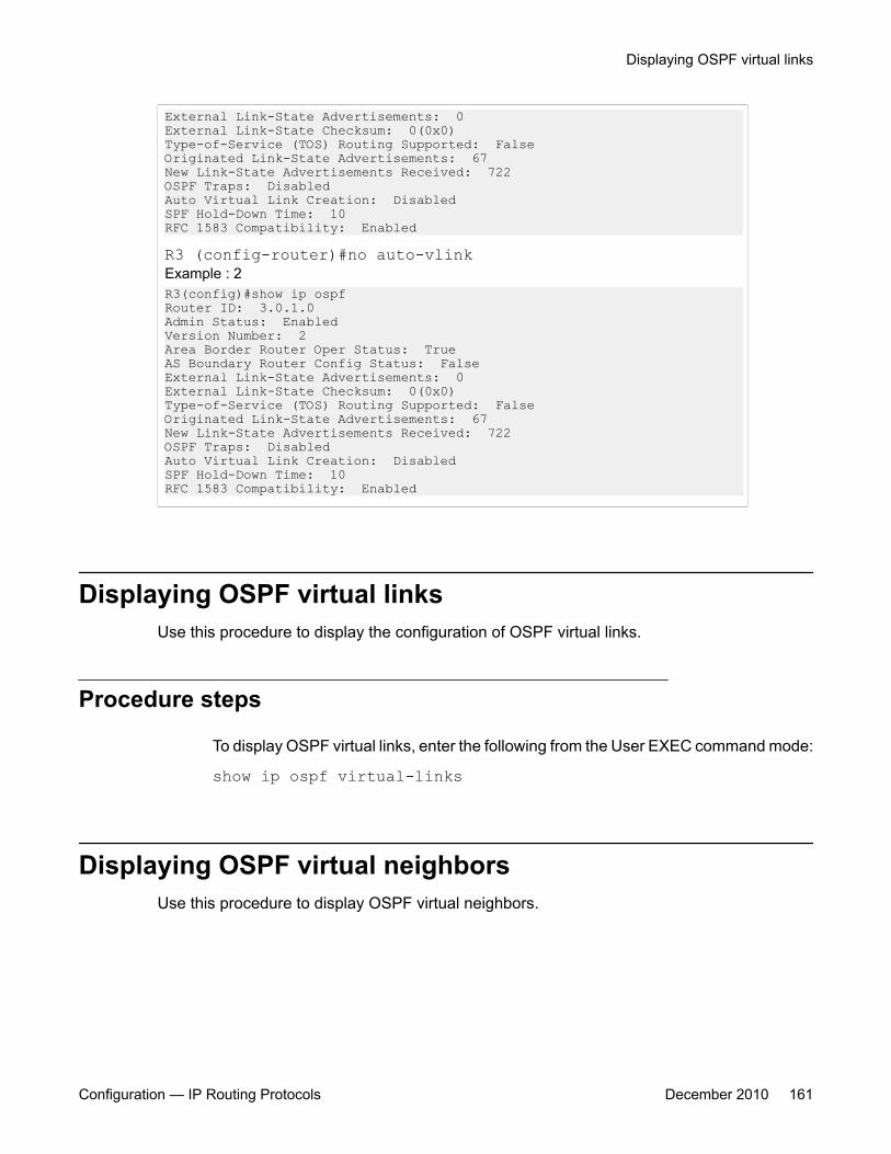
External Link-State Advertisements: 0External Link-State Checksum: 0(0x0)Type-of-Service (TOS) Routing Supported: FalseOriginated Link-State Advertisements: 67New Link-State Advertisements Received: 722OSPF Traps: DisabledAuto Virtual Link Creation: DisabledSPF Hold-Down Time: 10RFC 1583 Compatibility: Enabled
R3 (config-router)#no auto-vlinkExample : 2R3(config)#show ip ospfRouter ID: 3.0.1.0Admin Status: EnabledVersion Number: 2Area Border Router Oper Status: TrueAS Boundary Router Config Status: FalseExternal Link-State Advertisements: 0External Link-State Checksum: 0(0x0)Type-of-Service (TOS) Routing Supported: FalseOriginated Link-State Advertisements: 67New Link-State Advertisements Received: 722OSPF Traps: DisabledAuto Virtual Link Creation: DisabledSPF Hold-Down Time: 10RFC 1583 Compatibility: Enabled
Displaying OSPF virtual linksUse this procedure to display the configuration of OSPF virtual links.
Procedure steps
To display OSPF virtual links, enter the following from the User EXEC command mode:
show ip ospf virtual-links
Displaying OSPF virtual neighborsUse this procedure to display OSPF virtual neighbors.
Displaying OSPF virtual links
Configuration — IP Routing Protocols December 2010 161

Procedure steps
To display OSPF virtual neighbors, enter the following from the User EXEC commandmode:
show ip ospf virtual-neighbors
Configuring an OSPF host routeUse this procedure to add a host to a router.
Procedure steps
To add a host to a router, enter the following from the OSPF Router Configurationcommand mode:
[no] host-route <A.B.C.D.> metric <0-65535>
Variable definitionsThe following table describes the command variables.
Variable Value[no] Deletes a host route from ther router.
<A.B.C.D.> Specifies the host IP address.
metric <0-65535> Specifies an integer between 0 and 65535 representing theconfigured cost of the host route.
Job aid: example of configuring an OSPF host routeThe following is an example for creating a host route:R3(config)#router ospfR3(config-router)#host-route 11.11.11.111 metric 10R3(config-router)#show ip ospf host-route
OSPF configuration using ACLI
162 Configuration — IP Routing Protocols December 2010
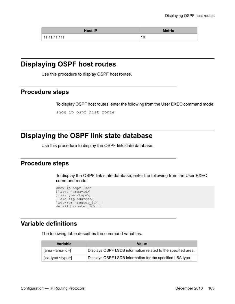
Host IP Metric11.11.11.111 10
Displaying OSPF host routesUse this procedure to display OSPF host routes.
Procedure steps
To display OSPF host routes, enter the following from the User EXEC command mode:
show ip ospf host-route
Displaying the OSPF link state databaseUse this procedure to display the OSPF link state database.
Procedure steps
To display the OSPF link state database, enter the following from the User EXECcommand mode:show ip ospf lsdb{[area <area-id>][lsa-type <type>][lsid <ip_address>][adv-rtr <router_id>] |detail [<router_id>] }
Variable definitionsThe following table describes the command variables.
Variable Value[area <area-id>] Displays OSPF LSDB information related to the specified area.
[lsa-type <type>] Displays OSPF LSDB information for the specified LSA type.
Displaying OSPF host routes
Configuration — IP Routing Protocols December 2010 163
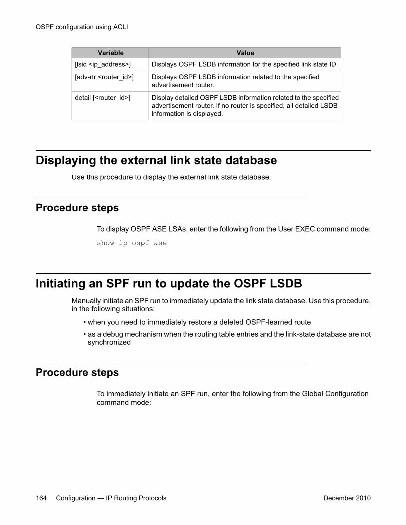
Variable Value[lsid <ip_address>] Displays OSPF LSDB information for the specified link state ID.
[adv-rtr <router_id>] Displays OSPF LSDB information related to the specifiedadvertisement router.
detail [<router_id>] Display detailed OSPF LSDB information related to the specifiedadvertisement router. If no router is specified, all detailed LSDBinformation is displayed.
Displaying the external link state databaseUse this procedure to display the external link state database.
Procedure steps
To display OSPF ASE LSAs, enter the following from the User EXEC command mode:
show ip ospf ase
Initiating an SPF run to update the OSPF LSDBManually initiate an SPF run to immediately update the link state database. Use this procedure,in the following situations:
• when you need to immediately restore a deleted OSPF-learned route• as a debug mechanism when the routing table entries and the link-state database are not
synchronized
Procedure steps
To immediately initiate an SPF run, enter the following from the Global Configurationcommand mode:
OSPF configuration using ACLI
164 Configuration — IP Routing Protocols December 2010
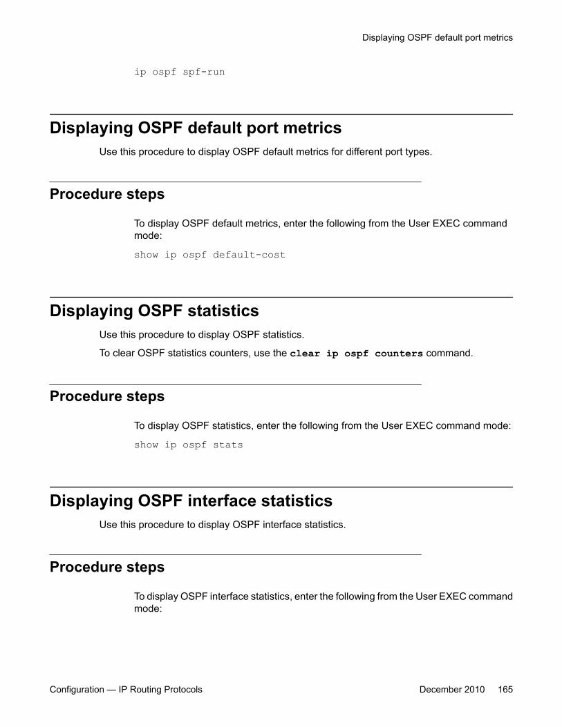
ip ospf spf-run
Displaying OSPF default port metricsUse this procedure to display OSPF default metrics for different port types.
Procedure steps
To display OSPF default metrics, enter the following from the User EXEC commandmode:
show ip ospf default-cost
Displaying OSPF statisticsUse this procedure to display OSPF statistics.
To clear OSPF statistics counters, use the clear ip ospf counters command.
Procedure steps
To display OSPF statistics, enter the following from the User EXEC command mode:
show ip ospf stats
Displaying OSPF interface statisticsUse this procedure to display OSPF interface statistics.
Procedure steps
To display OSPF interface statistics, enter the following from the User EXEC commandmode:
Displaying OSPF default port metrics
Configuration — IP Routing Protocols December 2010 165
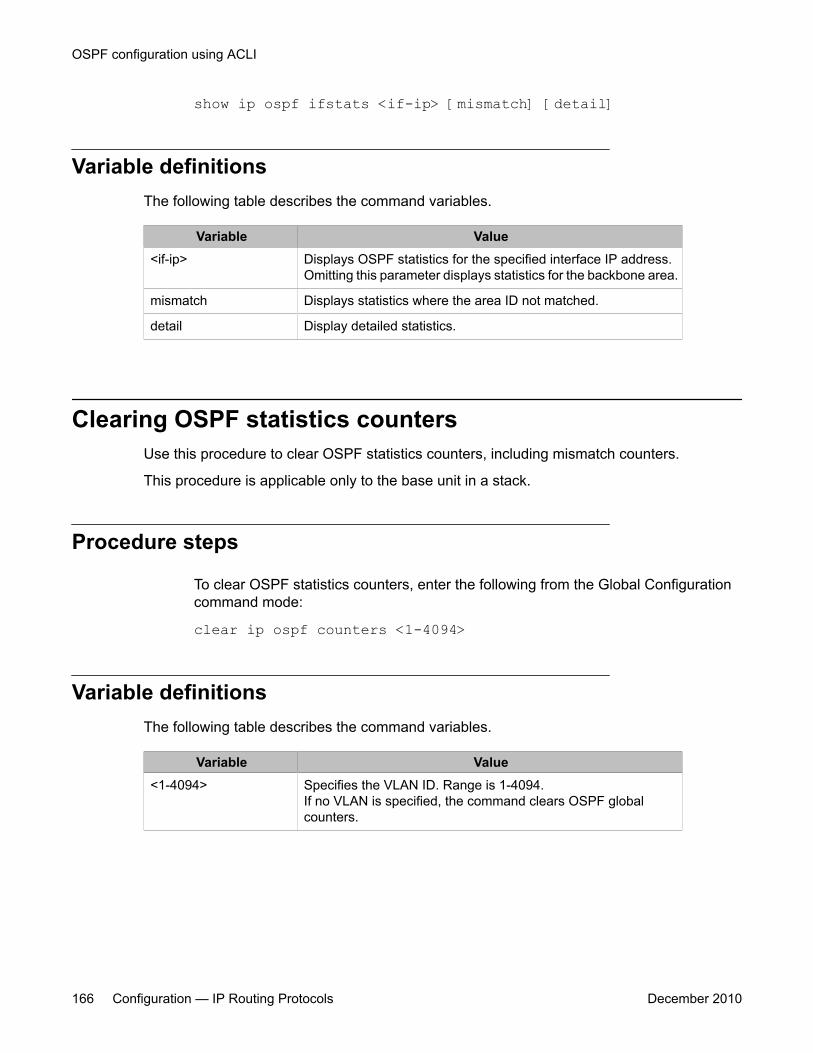
show ip ospf ifstats <if-ip> [mismatch] [detail]
Variable definitionsThe following table describes the command variables.
Variable Value<if-ip> Displays OSPF statistics for the specified interface IP address.
Omitting this parameter displays statistics for the backbone area.
mismatch Displays statistics where the area ID not matched.
detail Display detailed statistics.
Clearing OSPF statistics countersUse this procedure to clear OSPF statistics counters, including mismatch counters.
This procedure is applicable only to the base unit in a stack.
Procedure steps
To clear OSPF statistics counters, enter the following from the Global Configurationcommand mode:
clear ip ospf counters <1-4094>
Variable definitionsThe following table describes the command variables.
Variable Value<1-4094> Specifies the VLAN ID. Range is 1-4094.
If no VLAN is specified, the command clears OSPF globalcounters.
OSPF configuration using ACLI
166 Configuration — IP Routing Protocols December 2010
Chapter 10: OSPF configuration examplesusing ACLI
The following sections provide OSPF configuration examples using ACLI.
Navigation• Basic OSPF configuration examples on page 167
• Advanced OSPF configuration examples on page 170
Basic OSPF configuration examplesThis section contains the steps necessary for the initial configuration of OSPF on the switch.More advanced configuration examples can be found in Advanced OSPF configurationexamples on page 170.
Note:In many of the following configuration examples, a brouter port is used to create a connectionto the network core. This practice does not imply that a brouter port is the only means throughwhich a core connection can be established. The use of a brouter port is only one of manyways to create such a connection.
Basic OSPF configurationA basic OSPF configuration will learn OSPF routes from other OSPF devices and propagateroutes to other OSPF devices. The following procedure describes the creation of a basic OSPFconfiguration:
1. Log into User EXEC mode.
5530-24TFD> enable2. Log into Global Configuration mode.
5530-24TFD# config terminal
Configuration — IP Routing Protocols December 2010 167
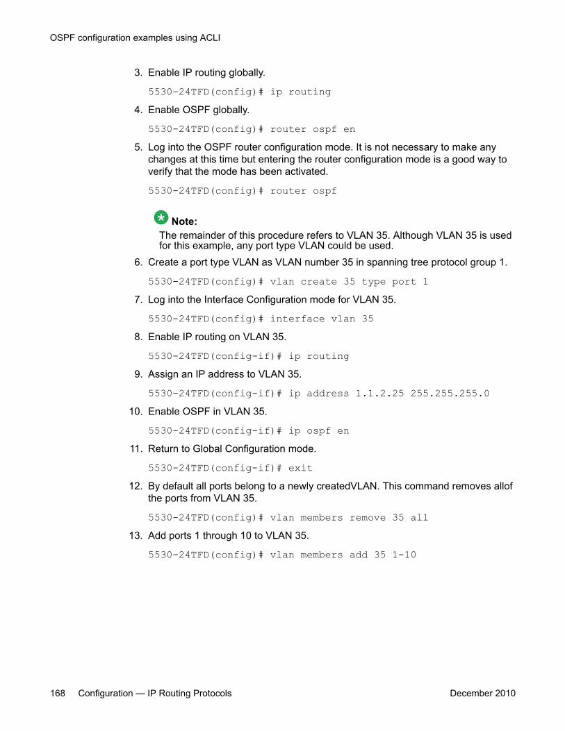
3. Enable IP routing globally.
5530-24TFD(config)# ip routing4. Enable OSPF globally.
5530-24TFD(config)# router ospf en5. Log into the OSPF router configuration mode. It is not necessary to make any
changes at this time but entering the router configuration mode is a good way toverify that the mode has been activated.
5530-24TFD(config)# router ospf
Note:The remainder of this procedure refers to VLAN 35. Although VLAN 35 is usedfor this example, any port type VLAN could be used.
6. Create a port type VLAN as VLAN number 35 in spanning tree protocol group 1.
5530-24TFD(config)# vlan create 35 type port 17. Log into the Interface Configuration mode for VLAN 35.
5530-24TFD(config)# interface vlan 358. Enable IP routing on VLAN 35.
5530-24TFD(config-if)# ip routing9. Assign an IP address to VLAN 35.
5530-24TFD(config-if)# ip address 1.1.2.25 255.255.255.010. Enable OSPF in VLAN 35.
5530-24TFD(config-if)# ip ospf en11. Return to Global Configuration mode.
5530-24TFD(config-if)# exit12. By default all ports belong to a newly createdVLAN. This command removes allof
the ports from VLAN 35.
5530-24TFD(config)# vlan members remove 35 all13. Add ports 1 through 10 to VLAN 35.
5530-24TFD(config)# vlan members add 35 1-10
OSPF configuration examples using ACLI
168 Configuration — IP Routing Protocols December 2010
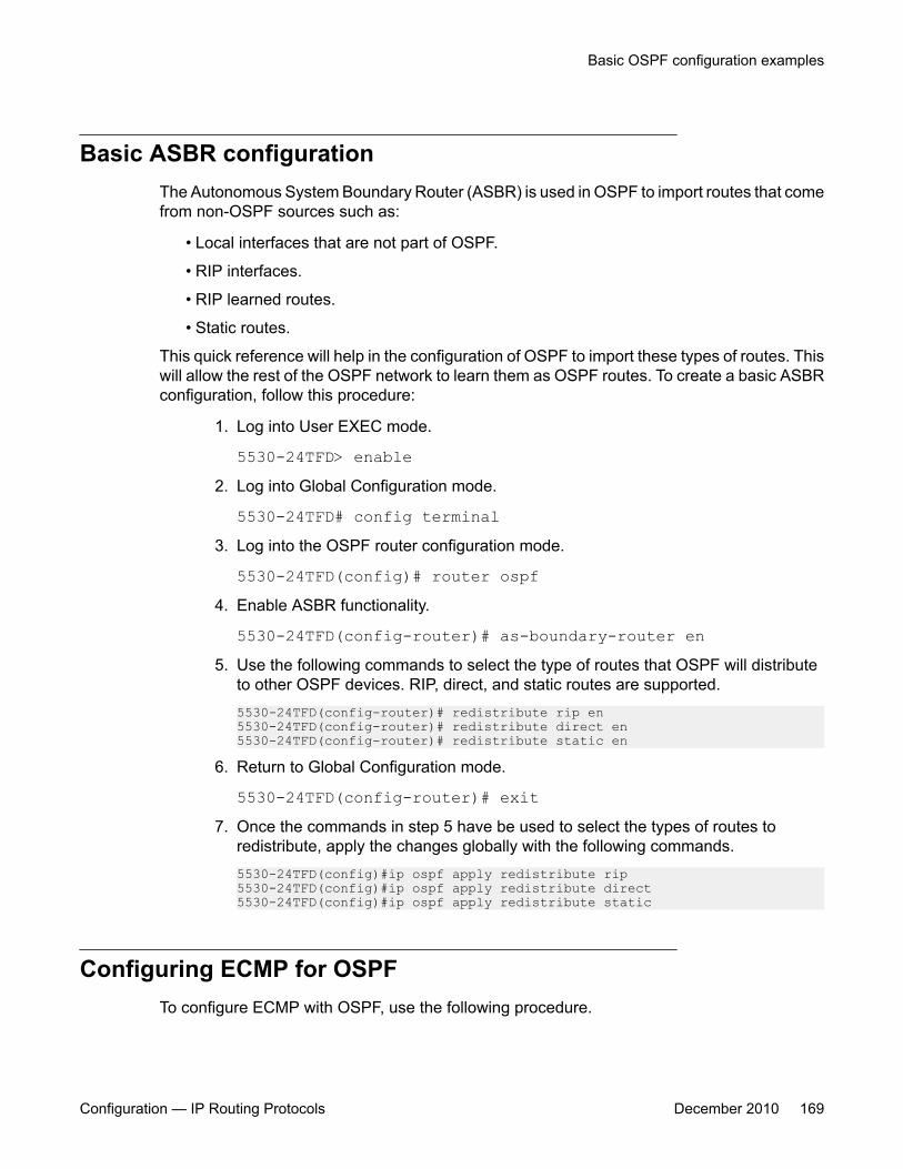
Basic ASBR configurationThe Autonomous System Boundary Router (ASBR) is used in OSPF to import routes that comefrom non-OSPF sources such as:
• Local interfaces that are not part of OSPF.
• RIP interfaces.
• RIP learned routes.
• Static routes.
This quick reference will help in the configuration of OSPF to import these types of routes. Thiswill allow the rest of the OSPF network to learn them as OSPF routes. To create a basic ASBRconfiguration, follow this procedure:
1. Log into User EXEC mode.
5530-24TFD> enable2. Log into Global Configuration mode.
5530-24TFD# config terminal3. Log into the OSPF router configuration mode.
5530-24TFD(config)# router ospf4. Enable ASBR functionality.
5530-24TFD(config-router)# as-boundary-router en5. Use the following commands to select the type of routes that OSPF will distribute
to other OSPF devices. RIP, direct, and static routes are supported.5530-24TFD(config-router)# redistribute rip en5530-24TFD(config-router)# redistribute direct en5530-24TFD(config-router)# redistribute static en
6. Return to Global Configuration mode.
5530-24TFD(config-router)# exit7. Once the commands in step 5 have be used to select the types of routes to
redistribute, apply the changes globally with the following commands.5530-24TFD(config)#ip ospf apply redistribute rip5530-24TFD(config)#ip ospf apply redistribute direct5530-24TFD(config)#ip ospf apply redistribute static
Configuring ECMP for OSPFTo configure ECMP with OSPF, use the following procedure.
Basic OSPF configuration examples
Configuration — IP Routing Protocols December 2010 169

Usage of ECMP with OSPF is not supported on the 5510 models.
1. Log into User EXEC mode.
5530-24TFD> enable2. Log into Global Configuration mode.
5530-24TFD# config terminal3. Set the number of ECMP paths to use with OSPF. Up to four paths can be used.
5530-24TFD(config)# ospf maximum-path 2This command tells the router to use up to two equal-cost paths to get to any OSPFnetwork destination.
4. The configuration can be verified using the following command.
5530-24TFD(config)# show ecmp
Advanced OSPF configuration examplesThis section contains examples of common OSPF-related configuration tasks.
The Avaya Ethernet Routing Switch 5000 Series supports the following OSPF standards:
• RFC 2328 (OSPF version 2)• RFC 1850 (OSPF Management Information Base)• RFC 2178 (OSPF MD5 cryptographic authentication)
This section provides examples of the common OSPF configuration tasks and includes theACLI commands used to create the configuration.
Configuring an IP OSPF interfaceAn OSPF interface can be configured on a brouter port or on a VLAN. The following sectiondemonstrates the creation of the example OSPF interface illustrated below.
OSPF configuration examples using ACLI
170 Configuration — IP Routing Protocols December 2010
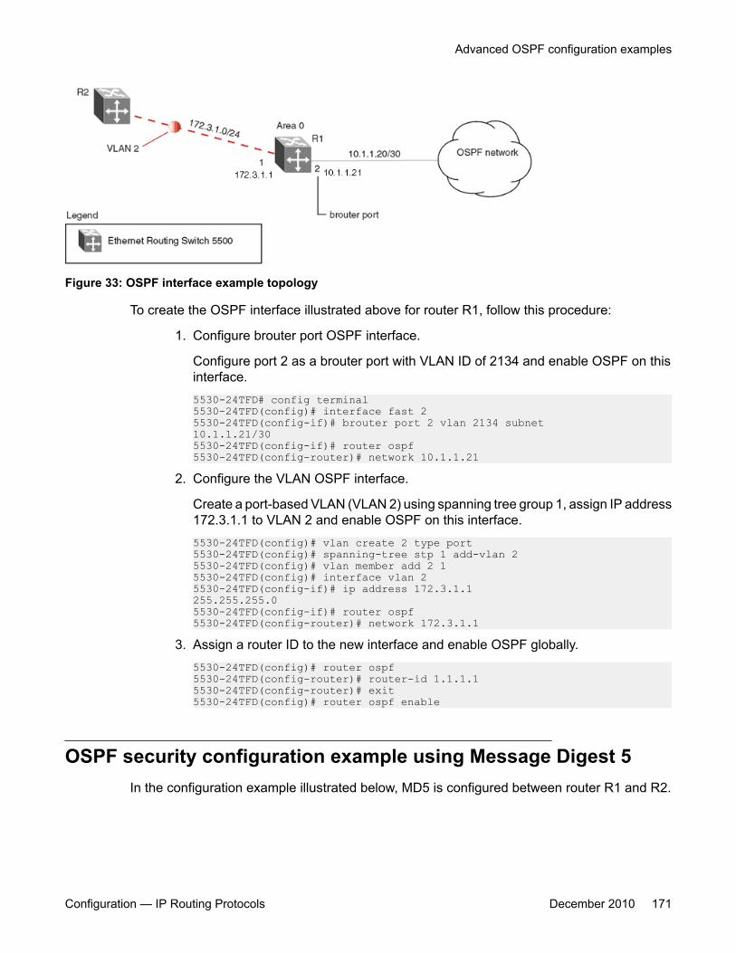
Figure 33: OSPF interface example topology
To create the OSPF interface illustrated above for router R1, follow this procedure:
1. Configure brouter port OSPF interface.
Configure port 2 as a brouter port with VLAN ID of 2134 and enable OSPF on thisinterface.5530-24TFD# config terminal5530-24TFD(config)# interface fast 25530-24TFD(config-if)# brouter port 2 vlan 2134 subnet10.1.1.21/305530-24TFD(config-if)# router ospf5530-24TFD(config-router)# network 10.1.1.21
2. Configure the VLAN OSPF interface.
Create a port-based VLAN (VLAN 2) using spanning tree group 1, assign IP address172.3.1.1 to VLAN 2 and enable OSPF on this interface.5530-24TFD(config)# vlan create 2 type port5530-24TFD(config)# spanning-tree stp 1 add-vlan 25530-24TFD(config)# vlan member add 2 15530-24TFD(config)# interface vlan 25530-24TFD(config-if)# ip address 172.3.1.1255.255.255.05530-24TFD(config-if)# router ospf5530-24TFD(config-router)# network 172.3.1.1
3. Assign a router ID to the new interface and enable OSPF globally.5530-24TFD(config)# router ospf5530-24TFD(config-router)# router-id 1.1.1.15530-24TFD(config-router)# exit5530-24TFD(config)# router ospf enable
OSPF security configuration example using Message Digest 5In the configuration example illustrated below, MD5 is configured between router R1 and R2.
Advanced OSPF configuration examples
Configuration — IP Routing Protocols December 2010 171
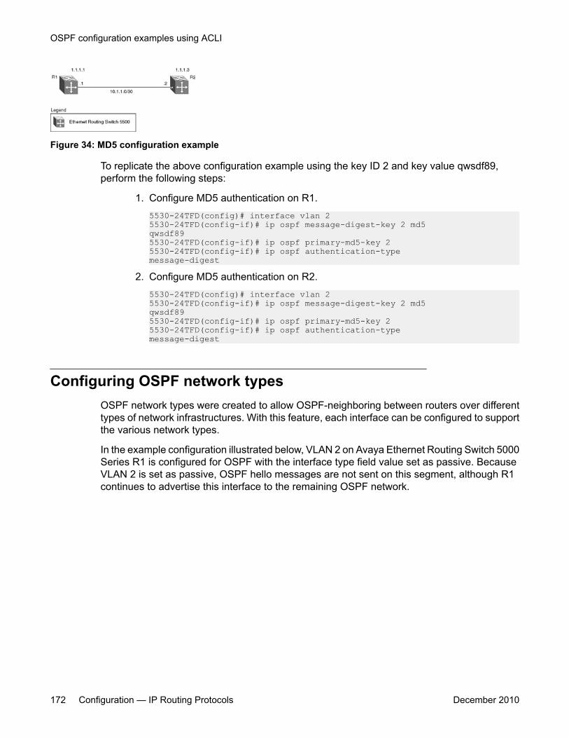
Figure 34: MD5 configuration example
To replicate the above configuration example using the key ID 2 and key value qwsdf89,perform the following steps:
1. Configure MD5 authentication on R1.5530-24TFD(config)# interface vlan 25530-24TFD(config-if)# ip ospf message-digest-key 2 md5qwsdf895530-24TFD(config-if)# ip ospf primary-md5-key 25530-24TFD(config-if)# ip ospf authentication-typemessage-digest
2. Configure MD5 authentication on R2.5530-24TFD(config)# interface vlan 25530-24TFD(config-if)# ip ospf message-digest-key 2 md5qwsdf895530-24TFD(config-if)# ip ospf primary-md5-key 25530-24TFD(config-if)# ip ospf authentication-typemessage-digest
Configuring OSPF network typesOSPF network types were created to allow OSPF-neighboring between routers over differenttypes of network infrastructures. With this feature, each interface can be configured to supportthe various network types.
In the example configuration illustrated below, VLAN 2 on Avaya Ethernet Routing Switch 5000Series R1 is configured for OSPF with the interface type field value set as passive. BecauseVLAN 2 is set as passive, OSPF hello messages are not sent on this segment, although R1continues to advertise this interface to the remaining OSPF network.
OSPF configuration examples using ACLI
172 Configuration — IP Routing Protocols December 2010
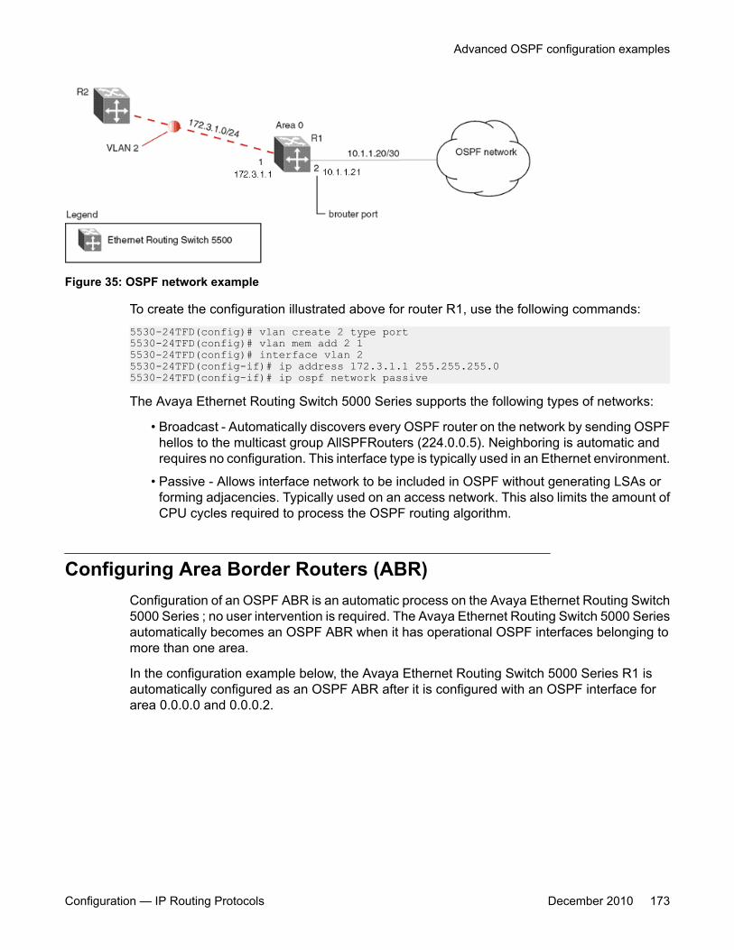
Figure 35: OSPF network example
To create the configuration illustrated above for router R1, use the following commands:5530-24TFD(config)# vlan create 2 type port5530-24TFD(config)# vlan mem add 2 15530-24TFD(config)# interface vlan 25530-24TFD(config-if)# ip address 172.3.1.1 255.255.255.05530-24TFD(config-if)# ip ospf network passive
The Avaya Ethernet Routing Switch 5000 Series supports the following types of networks:
• Broadcast - Automatically discovers every OSPF router on the network by sending OSPFhellos to the multicast group AllSPFRouters (224.0.0.5). Neighboring is automatic andrequires no configuration. This interface type is typically used in an Ethernet environment.
• Passive - Allows interface network to be included in OSPF without generating LSAs orforming adjacencies. Typically used on an access network. This also limits the amount ofCPU cycles required to process the OSPF routing algorithm.
Configuring Area Border Routers (ABR)Configuration of an OSPF ABR is an automatic process on the Avaya Ethernet Routing Switch5000 Series ; no user intervention is required. The Avaya Ethernet Routing Switch 5000 Seriesautomatically becomes an OSPF ABR when it has operational OSPF interfaces belonging tomore than one area.
In the configuration example below, the Avaya Ethernet Routing Switch 5000 Series R1 isautomatically configured as an OSPF ABR after it is configured with an OSPF interface forarea 0.0.0.0 and 0.0.0.2.
Advanced OSPF configuration examples
Configuration — IP Routing Protocols December 2010 173
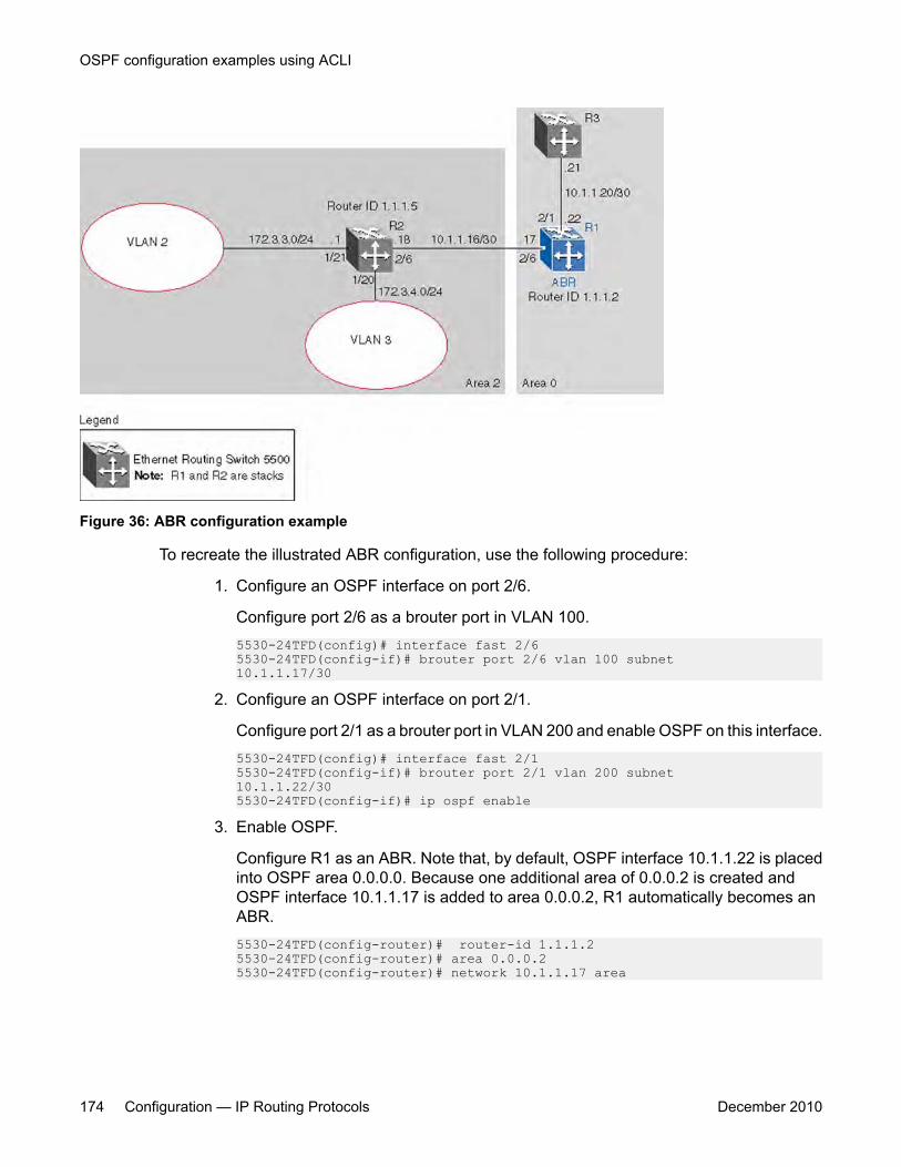
Figure 36: ABR configuration example
To recreate the illustrated ABR configuration, use the following procedure:
1. Configure an OSPF interface on port 2/6.
Configure port 2/6 as a brouter port in VLAN 100.5530-24TFD(config)# interface fast 2/65530-24TFD(config-if)# brouter port 2/6 vlan 100 subnet10.1.1.17/30
2. Configure an OSPF interface on port 2/1.
Configure port 2/1 as a brouter port in VLAN 200 and enable OSPF on this interface.5530-24TFD(config)# interface fast 2/15530-24TFD(config-if)# brouter port 2/1 vlan 200 subnet10.1.1.22/305530-24TFD(config-if)# ip ospf enable
3. Enable OSPF.
Configure R1 as an ABR. Note that, by default, OSPF interface 10.1.1.22 is placedinto OSPF area 0.0.0.0. Because one additional area of 0.0.0.2 is created andOSPF interface 10.1.1.17 is added to area 0.0.0.2, R1 automatically becomes anABR.5530-24TFD(config-router)# router-id 1.1.1.25530-24TFD(config-router)# area 0.0.0.25530-24TFD(config-router)# network 10.1.1.17 area
OSPF configuration examples using ACLI
174 Configuration — IP Routing Protocols December 2010
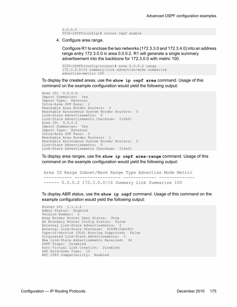
0.0.0.25530-24TFD(config)# router ospf enable
4. Configure area range.
Configure R1 to enclose the two networks (172.3.3.0 and 172.3.4.0) into an addressrange entry 172.3.0.0 in area 0.0.0.2. R1 will generate a single summaryadvertisement into the backbone for 172.3.0.0 with metric 100.5530-24TFD(config-router)# area 0.0.0.2 range172.3.0.0/16 summary-link advertise-mode summarizeadvertise-metric 100
To display the created areas, use the show ip ospf area command. Usage of thiscommand on the example configuration would yield the following output:Area ID: 0.0.0.0Import Summaries: YesImport Type: ExternalIntra-Area SPF Runs: 2Reachable Area Border Routers: 0Reachable Autonomous System Border Routers: 0Link-State Advertisements: 0Link-State Advertisements Checksum: 0(0x0)Area ID: 0.0.0.2Import Summaries: YesImport Type: ExternalIntra-Area SPF Runs: 2Reachable Area Border Routers: 1Reachable Autonomous System Border Routers: 0Link-State Advertisements: 0Link-State Advertisements Checksum: 0(0x0)
To display area ranges, use the show ip ospf area-range command. Usage of thiscommand on the example configuration would yield the following output:
Area ID Range Subnet/Mask Range Type Advertise Mode Metric----------- ------------------ ------------- -------------------- 0.0.0.2 172.3.0.0/16 Summary Link Summarize 100
To display ABR status, use the show ip ospf command. Usage of this command on theexample configuration would yield the following output:Router ID: 1.1.1.2Admin Status: EnabledVersion Number: 2Area Border Router Oper Status: TrueAS Boundary Router Config Status: FalseExternal Link-State Advertisements: 2External Link-State Checksum: 45698(0xb282)Type-of-Service (TOS) Routing Supported: FalseOriginated Link-State Advertisements: 5New Link-State Advertisements Received: 34OSPF Traps: DisabledAuto Virtual Link Creation: DisabledSPF Hold-Down Time: 10RFC 1583 Compatibility: Enabled
Advanced OSPF configuration examples
Configuration — IP Routing Protocols December 2010 175
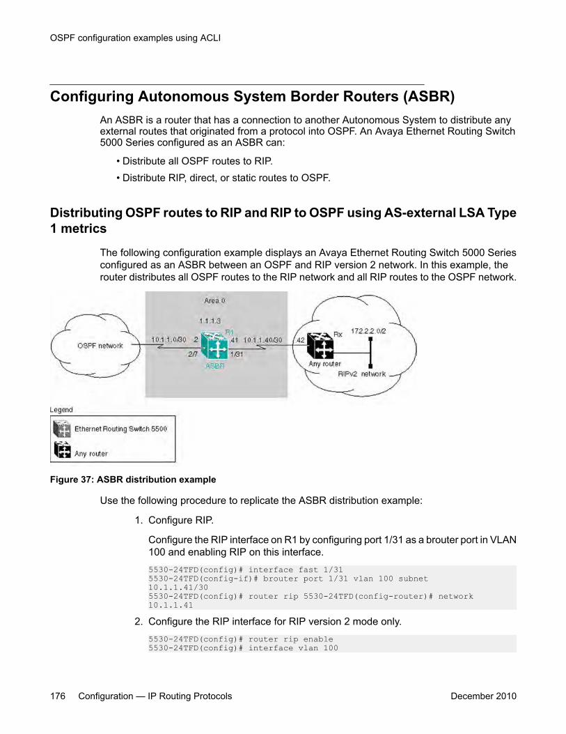
Configuring Autonomous System Border Routers (ASBR)An ASBR is a router that has a connection to another Autonomous System to distribute anyexternal routes that originated from a protocol into OSPF. An Avaya Ethernet Routing Switch5000 Series configured as an ASBR can:
• Distribute all OSPF routes to RIP.• Distribute RIP, direct, or static routes to OSPF.
Distributing OSPF routes to RIP and RIP to OSPF using AS-external LSA Type1 metrics
The following configuration example displays an Avaya Ethernet Routing Switch 5000 Seriesconfigured as an ASBR between an OSPF and RIP version 2 network. In this example, therouter distributes all OSPF routes to the RIP network and all RIP routes to the OSPF network.
Figure 37: ASBR distribution example
Use the following procedure to replicate the ASBR distribution example:
1. Configure RIP.
Configure the RIP interface on R1 by configuring port 1/31 as a brouter port in VLAN100 and enabling RIP on this interface.5530-24TFD(config)# interface fast 1/315530-24TFD(config-if)# brouter port 1/31 vlan 100 subnet10.1.1.41/305530-24TFD(config)# router rip 5530-24TFD(config-router)# network 10.1.1.41
2. Configure the RIP interface for RIP version 2 mode only.5530-24TFD(config)# router rip enable5530-24TFD(config)# interface vlan 100
OSPF configuration examples using ACLI
176 Configuration — IP Routing Protocols December 2010
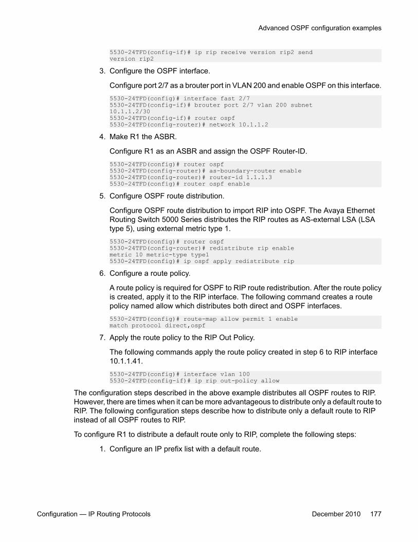
5530-24TFD(config-if)# ip rip receive version rip2 sendversion rip2
3. Configure the OSPF interface.
Configure port 2/7 as a brouter port in VLAN 200 and enable OSPF on this interface.5530-24TFD(config)# interface fast 2/75530-24TFD(config-if)# brouter port 2/7 vlan 200 subnet10.1.1.2/305530-24TFD(config-if)# router ospf5530-24TFD(config-router)# network 10.1.1.2
4. Make R1 the ASBR.
Configure R1 as an ASBR and assign the OSPF Router-ID.5530-24TFD(config)# router ospf5530-24TFD(config-router)# as-boundary-router enable5530-24TFD(config-router)# router-id 1.1.1.35530-24TFD(config)# router ospf enable
5. Configure OSPF route distribution.
Configure OSPF route distribution to import RIP into OSPF. The Avaya EthernetRouting Switch 5000 Series distributes the RIP routes as AS-external LSA (LSAtype 5), using external metric type 1.5530-24TFD(config)# router ospf5530-24TFD(config-router)# redistribute rip enablemetric 10 metric-type type15530-24TFD(config)# ip ospf apply redistribute rip
6. Configure a route policy.
A route policy is required for OSPF to RIP route redistribution. After the route policyis created, apply it to the RIP interface. The following command creates a routepolicy named allow which distributes both direct and OSPF interfaces.5530-24TFD(config)# route-map allow permit 1 enablematch protocol direct,ospf
7. Apply the route policy to the RIP Out Policy.
The following commands apply the route policy created in step 6 to RIP interface10.1.1.41.5530-24TFD(config)# interface vlan 1005530-24TFD(config-if)# ip rip out-policy allow
The configuration steps described in the above example distributes all OSPF routes to RIP.However, there are times when it can be more advantageous to distribute only a default route toRIP. The following configuration steps describe how to distribute only a default route to RIPinstead of all OSPF routes to RIP.
To configure R1 to distribute a default route only to RIP, complete the following steps:
1. Configure an IP prefix list with a default route.
Advanced OSPF configuration examples
Configuration — IP Routing Protocols December 2010 177
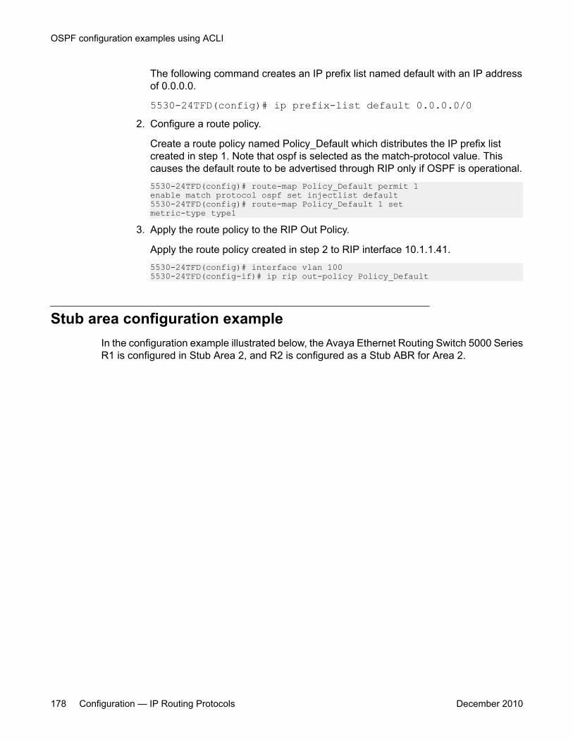
The following command creates an IP prefix list named default with an IP addressof 0.0.0.0.
5530-24TFD(config)# ip prefix-list default 0.0.0.0/02. Configure a route policy.
Create a route policy named Policy_Default which distributes the IP prefix listcreated in step 1. Note that ospf is selected as the match-protocol value. Thiscauses the default route to be advertised through RIP only if OSPF is operational.5530-24TFD(config)# route-map Policy_Default permit 1enable match protocol ospf set injectlist default5530-24TFD(config)# route-map Policy_Default 1 setmetric-type type1
3. Apply the route policy to the RIP Out Policy.
Apply the route policy created in step 2 to RIP interface 10.1.1.41.5530-24TFD(config)# interface vlan 1005530-24TFD(config-if)# ip rip out-policy Policy_Default
Stub area configuration exampleIn the configuration example illustrated below, the Avaya Ethernet Routing Switch 5000 SeriesR1 is configured in Stub Area 2, and R2 is configured as a Stub ABR for Area 2.
OSPF configuration examples using ACLI
178 Configuration — IP Routing Protocols December 2010
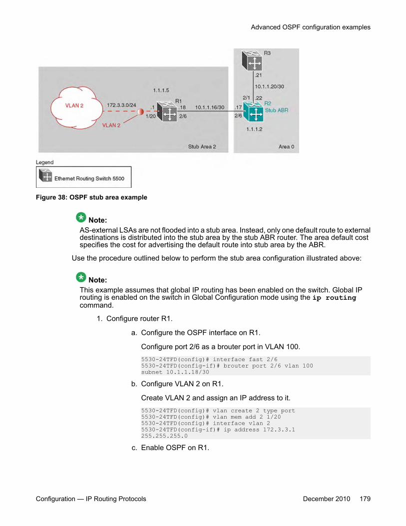
Figure 38: OSPF stub area example
Note:AS-external LSAs are not flooded into a stub area. Instead, only one default route to externaldestinations is distributed into the stub area by the stub ABR router. The area default costspecifies the cost for advertising the default route into stub area by the ABR.
Use the procedure outlined below to perform the stub area configuration illustrated above:
Note:This example assumes that global IP routing has been enabled on the switch. Global IProuting is enabled on the switch in Global Configuration mode using the ip routingcommand.
1. Configure router R1.
a. Configure the OSPF interface on R1.
Configure port 2/6 as a brouter port in VLAN 100.5530-24TFD(config)# interface fast 2/65530-24TFD(config-if)# brouter port 2/6 vlan 100subnet 10.1.1.18/30
b. Configure VLAN 2 on R1.
Create VLAN 2 and assign an IP address to it.5530-24TFD(config)# vlan create 2 type port5530-24TFD(config)# vlan mem add 2 1/205530-24TFD(config)# interface vlan 25530-24TFD(config-if)# ip address 172.3.3.1255.255.255.0
c. Enable OSPF on R1.
Advanced OSPF configuration examples
Configuration — IP Routing Protocols December 2010 179
Configure R1 in stub area 2 with the Router-ID 1.1.1.5. Add the OSPFinterfaces to area 2 and enable OSPF on these interfaces.5530-24TFD(config-router)# router-id 1.1.1.55530-24TFD(config-router)# area 0.0.0.2 importnoexternal5530-24TFD(config-router)# network 10.1.1.18 area0.0.0.25530-24TFD(config-router)# network 172.3.3.1 area0.0.0.25530-24TFD(config)# router ospf enable
2. Configure router R2.
a. Configure the OSPF interface on R2.
Configure port 2/6 as a brouter port in VLAN 100.5530-24TFD(config)# interface fast 2/65530-24TFD(config-if)# brouter port 2/6 vlan 100subnet 10.1.1.17/30
b. Configure the second OSPF interface on R2.
Configure port 2/1 as a brouter port in VLAN 300. Enable OSPF on thisinterface.5530-24TFD(config)# interface fast 2/15530-24TFD(config-if)# brouter port 2/1 vlan 300subnet 10.1.1.22/305530-24TFD(config-if)# ip ospf enable
c. Enable OSPF on R2.
Configure R2 in stub area 2 with an area default cost of 10. Disable importsummary to prevent R2 from sending summary LSAs of area 0 into area2. R2 will originate only summary LSA for default route into area 2. Notethat, by default, OSPF interface 10.1.1.22 is placed into OSPF area0.0.0.0. Because one additional area of 0.0.0.2 is added and OSPFinterface 10.1.1.17 is added to area 0.0.0.2, R2 automatically becomesa stub ABR.5530-24TFD(config-router)# router-id 1.1.1.25530-24TFD(config-router)# area 0.0.0.2 importnoexternal5530-24TFD(config-router)# no area 0.0.0.2import-summary enable5530-24TFD(config-router)# area 0.0.0.2 default-cost105530-24TFD(config-router)# network 10.1.1.17 area0.0.0.25530-24TFD(config)# router ospf enable
NSSA configuration exampleThe NSSA configuration example illustrated below demonstrates a Avaya Ethernet RoutingSwitch 5000 Series configured as a NSSA ASBR router.
OSPF configuration examples using ACLI
180 Configuration — IP Routing Protocols December 2010
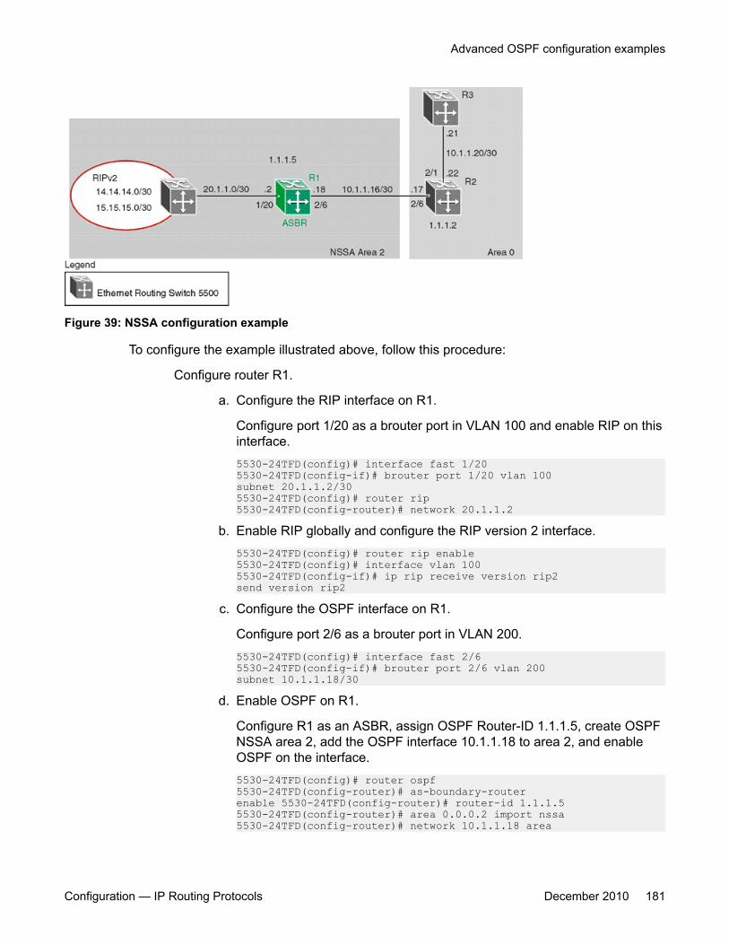
Figure 39: NSSA configuration example
To configure the example illustrated above, follow this procedure:
Configure router R1.
a. Configure the RIP interface on R1.
Configure port 1/20 as a brouter port in VLAN 100 and enable RIP on thisinterface.5530-24TFD(config)# interface fast 1/205530-24TFD(config-if)# brouter port 1/20 vlan 100subnet 20.1.1.2/305530-24TFD(config)# router rip5530-24TFD(config-router)# network 20.1.1.2
b. Enable RIP globally and configure the RIP version 2 interface.5530-24TFD(config)# router rip enable5530-24TFD(config)# interface vlan 1005530-24TFD(config-if)# ip rip receive version rip2send version rip2
c. Configure the OSPF interface on R1.
Configure port 2/6 as a brouter port in VLAN 200.5530-24TFD(config)# interface fast 2/65530-24TFD(config-if)# brouter port 2/6 vlan 200subnet 10.1.1.18/30
d. Enable OSPF on R1.
Configure R1 as an ASBR, assign OSPF Router-ID 1.1.1.5, create OSPFNSSA area 2, add the OSPF interface 10.1.1.18 to area 2, and enableOSPF on the interface.5530-24TFD(config)# router ospf5530-24TFD(config-router)# as-boundary-routerenable 5530-24TFD(config-router)# router-id 1.1.1.55530-24TFD(config-router)# area 0.0.0.2 import nssa5530-24TFD(config-router)# network 10.1.1.18 area
Advanced OSPF configuration examples
Configuration — IP Routing Protocols December 2010 181
0.0.0.25530-24TFD(config)# router ospf enable
e. Configure a route policy to distribute Direct and OSPF to RIP.
Create a route policy named Rip_Dist that distributes directly connected andOSPF routes into RIP.5530-24TFD(config)# route-map Rip_Dist permit 1enable match protocol direct,ospf set metric-typetype1
f. Apply the Rip_Dist route policy to RIP Out Policy.5530-24TFD(config)# interface vlan 1005530-24TFD(config-if)# ip rip out-policy Rip_Dist
g. Configure OSPF route distribution to distribute RIP routes as AS-externalLSA type 1.5530-24TFD(config)# router ospf5530-24TFD(config-router)# redistribute rip enablemetric-type type15530-24TFD(config)# ip ospf apply redistribute rip
Controlling NSSA external router advertisementsIn an OSPF NSSA, the NSSA N/P-bit (in the OSPF hello packets Options field) is used totell the ABR which external routes can be advertised to other areas. When the NSSA N/P-bitis set true, the ABR exports the external route. This is the default setting for the Avaya EthernetRouting Switch 5000 Series . When the NSSA N/P-bit is not set true, the ABR drops the externalroute. A route policy can be created on the Avaya Ethernet Routing Switch 5000 Series tomanipulate the N/ p-bit value.
For example, the illustration below shows a RIP network located in NSSA 2. If advertising the15.15.15.0/24 network to area 0 is the only desired action, perform the following tasks:
• Enable R1 as an OSPF ASBR.
• Create NSSA area 0.0.0.2.
• Create a route policy to advertise OSPF and direct interfaces to RIP.
• Create a route policy to only advertise RIP network 15.15.15.0/24 to area 0 by using theNSSA N/P-bit.
OSPF configuration examples using ACLI
182 Configuration — IP Routing Protocols December 2010
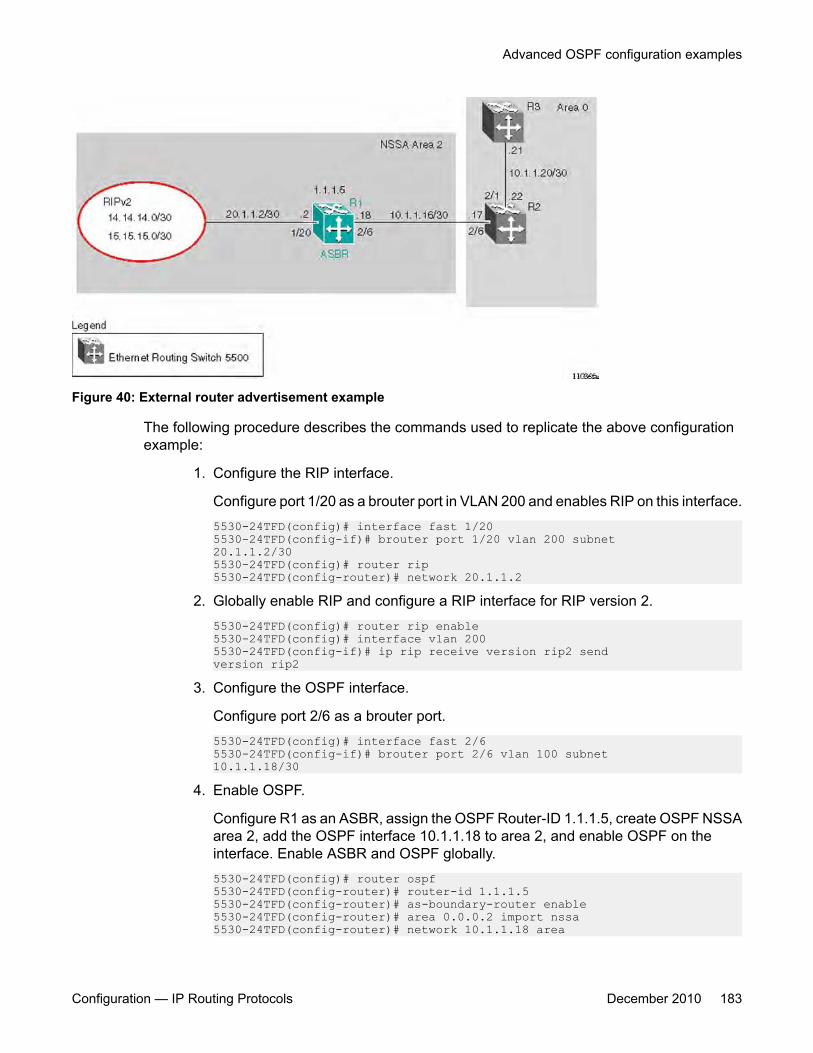
Figure 40: External router advertisement example
The following procedure describes the commands used to replicate the above configurationexample:
1. Configure the RIP interface.
Configure port 1/20 as a brouter port in VLAN 200 and enables RIP on this interface.5530-24TFD(config)# interface fast 1/205530-24TFD(config-if)# brouter port 1/20 vlan 200 subnet20.1.1.2/305530-24TFD(config)# router rip5530-24TFD(config-router)# network 20.1.1.2
2. Globally enable RIP and configure a RIP interface for RIP version 2.5530-24TFD(config)# router rip enable5530-24TFD(config)# interface vlan 2005530-24TFD(config-if)# ip rip receive version rip2 sendversion rip2
3. Configure the OSPF interface.
Configure port 2/6 as a brouter port.5530-24TFD(config)# interface fast 2/65530-24TFD(config-if)# brouter port 2/6 vlan 100 subnet10.1.1.18/30
4. Enable OSPF.
Configure R1 as an ASBR, assign the OSPF Router-ID 1.1.1.5, create OSPF NSSAarea 2, add the OSPF interface 10.1.1.18 to area 2, and enable OSPF on theinterface. Enable ASBR and OSPF globally.5530-24TFD(config)# router ospf5530-24TFD(config-router)# router-id 1.1.1.55530-24TFD(config-router)# as-boundary-router enable5530-24TFD(config-router)# area 0.0.0.2 import nssa5530-24TFD(config-router)# network 10.1.1.18 area
Advanced OSPF configuration examples
Configuration — IP Routing Protocols December 2010 183

0.0.0.25530-24TFD(config)# router ospf enable
5. Create a route policy named Rip_Dist that distributes directly connected and OSPFroutes into RIP.5530-24TFD(config)# route-map Rip_Dist permit 1 enablematch protocol direct,ospf set metric-type type1
6. Apply route policy to RIP Out Policy.5530-24TFD(config)# interface vlan 2005530-24TFD(config-if)# ip rip out-policy Rip_Dist
7. Add two prefix lists (15net and 14net) that are associated with the networkaddresses from the RIP version 2 network.5530-24TFD(config)# ip prefix-list 15net 15.15.15.0/245530-24TFD(config)# ip prefix-list 14net 14.14.14.0/24
8. Create a route policy named P_bit that sets the NSSA N/P-bit only for the prefix listnamed 15net.5530-24TFD(config)# route-map P_bit permit 1 enablematch network 15net set nssa-pbit enable5530-24TFD(config)# route-map P_bit permit 2 enablematch network 14net5530-24TFD(config)# no route-map P_bit 2 set nssa-pbitenable
9. Configure OSPF route distribution to distribute RIP routes as AS-external LSA Type1.5530-24TFD(config)# router ospf5530-24TFD(config-router)# redistribute rip enablemetric-type type1 route-policy P_bit5530-24TFD(config)# ip ospf apply redistribute rip
Configuring a multi-area complexThe multi-area complex configuration example described in this section uses five AvayaEthernet Routing Switch 5000 Series devices (R1 to R5) in a multi-area configuration.
Many of the concepts and topology descriptions that are used in this example configurationare described in the previous sections of this chapter. The concepts shown in those examplesare combined in this example configuration to show a real world topology example withcommand descriptions.
OSPF configuration examples using ACLI
184 Configuration — IP Routing Protocols December 2010
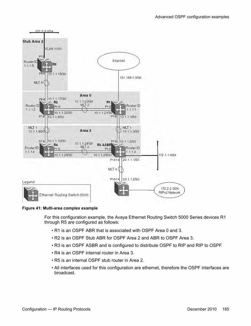
Figure 41: Multi-area complex example
For this configuration example, the Avaya Ethernet Routing Switch 5000 Series devices R1through R5 are configured as follows:
• R1 is an OSPF ABR that is associated with OSPF Area 0 and 3.• R2 is an OSPF Stub ABR for OSPF Area 2 and ABR to OSPF Area 3.• R3 is an OSPF ASBR and is configured to distribute OSPF to RIP and RIP to OSPF.• R4 is an OSPF internal router in Area 3.• R5 is an internal OSPF stub router in Area 2.• All interfaces used for this configuration are ethernet, therefore the OSPF interfaces are
broadcast.
Advanced OSPF configuration examples
Configuration — IP Routing Protocols December 2010 185
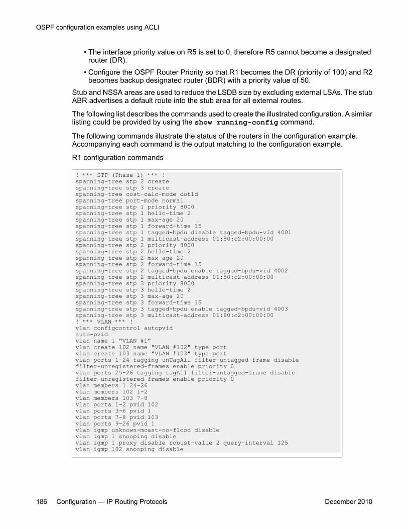
• The interface priority value on R5 is set to 0, therefore R5 cannot become a designatedrouter (DR).
• Configure the OSPF Router Priority so that R1 becomes the DR (priority of 100) and R2becomes backup designated router (BDR) with a priority value of 50.
Stub and NSSA areas are used to reduce the LSDB size by excluding external LSAs. The stubABR advertises a default route into the stub area for all external routes.
The following list describes the commands used to create the illustrated configuration. A similarlisting could be provided by using the show running-config command.
The following commands illustrate the status of the routers in the configuration example.Accompanying each command is the output matching to the configuration example.
R1 configuration commands
! *** STP (Phase 1) *** !spanning-tree stp 2 createspanning-tree stp 3 createspanning-tree cost-calc-mode dot1dspanning-tree port-mode normalspanning-tree stp 1 priority 8000spanning-tree stp 1 hello-time 2spanning-tree stp 1 max-age 20spanning-tree stp 1 forward-time 15spanning-tree stp 1 tagged-bpdu disable tagged-bpdu-vid 4001spanning-tree stp 1 multicast-address 01:80:c2:00:00:00spanning-tree stp 2 priority 8000spanning-tree stp 2 hello-time 2spanning-tree stp 2 max-age 20spanning-tree stp 2 forward-time 15spanning-tree stp 2 tagged-bpdu enable tagged-bpdu-vid 4002spanning-tree stp 2 multicast-address 01:80:c2:00:00:00spanning-tree stp 3 priority 8000spanning-tree stp 3 hello-time 2spanning-tree stp 3 max-age 20spanning-tree stp 3 forward-time 15spanning-tree stp 3 tagged-bpdu enable tagged-bpdu-vid 4003spanning-tree stp 3 multicast-address 01:80:c2:00:00:00! *** VLAN *** !vlan configcontrol autopvidauto-pvidvlan name 1 "VLAN #1"vlan create 102 name "VLAN #102" type portvlan create 103 name "VLAN #103" type portvlan ports 1-24 tagging unTagAll filter-untagged-frame disablefilter-unregistered-frames enable priority 0vlan ports 25-26 tagging tagAll filter-untagged-frame disablefilter-unregistered-frames enable priority 0vlan members 1 24-26vlan members 102 1-2vlan members 103 7-8vlan ports 1-2 pvid 102vlan ports 3-6 pvid 1vlan ports 7-8 pvid 103vlan ports 9-26 pvid 1vlan igmp unknown-mcast-no-flood disablevlan igmp 1 snooping disablevlan igmp 1 proxy disable robust-value 2 query-interval 125vlan igmp 102 snooping disable
OSPF configuration examples using ACLI
186 Configuration — IP Routing Protocols December 2010
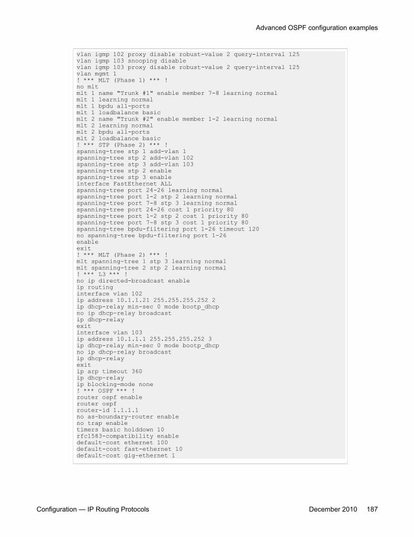
vlan igmp 102 proxy disable robust-value 2 query-interval 125vlan igmp 103 snooping disablevlan igmp 103 proxy disable robust-value 2 query-interval 125vlan mgmt 1! *** MLT (Phase 1) *** !no mltmlt 1 name "Trunk #1" enable member 7-8 learning normalmlt 1 learning normalmlt 1 bpdu all-portsmlt 1 loadbalance basicmlt 2 name "Trunk #2" enable member 1-2 learning normalmlt 2 learning normalmlt 2 bpdu all-portsmlt 2 loadbalance basic! *** STP (Phase 2) *** !spanning-tree stp 1 add-vlan 1spanning-tree stp 2 add-vlan 102spanning-tree stp 3 add-vlan 103spanning-tree stp 2 enablespanning-tree stp 3 enableinterface FastEthernet ALLspanning-tree port 24-26 learning normalspanning-tree port 1-2 stp 2 learning normalspanning-tree port 7-8 stp 3 learning normalspanning-tree port 24-26 cost 1 priority 80spanning-tree port 1-2 stp 2 cost 1 priority 80spanning-tree port 7-8 stp 3 cost 1 priority 80spanning-tree bpdu-filtering port 1-26 timeout 120no spanning-tree bpdu-filtering port 1-26enableexit! *** MLT (Phase 2) *** !mlt spanning-tree 1 stp 3 learning normalmlt spanning-tree 2 stp 2 learning normal! *** L3 *** !no ip directed-broadcast enableip routinginterface vlan 102ip address 10.1.1.21 255.255.255.252 2ip dhcp-relay min-sec 0 mode bootp_dhcpno ip dhcp-relay broadcastip dhcp-relayexitinterface vlan 103ip address 10.1.1.1 255.255.255.252 3ip dhcp-relay min-sec 0 mode bootp_dhcpno ip dhcp-relay broadcastip dhcp-relayexitip arp timeout 360ip dhcp-relayip blocking-mode none! *** OSPF *** !router ospf enablerouter ospfrouter-id 1.1.1.1no as-boundary-router enableno trap enabletimers basic holddown 10rfc1583-compatibility enabledefault-cost ethernet 100default-cost fast-ethernet 10default-cost gig-ethernet 1
Advanced OSPF configuration examples
Configuration — IP Routing Protocols December 2010 187
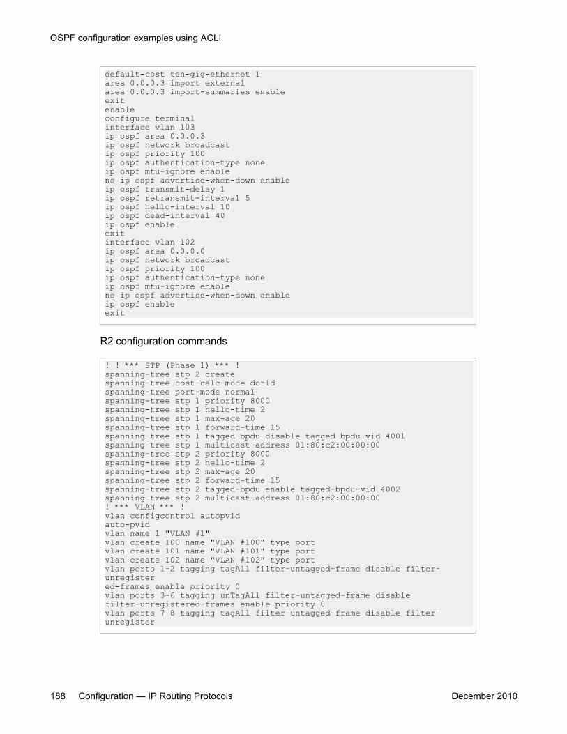
default-cost ten-gig-ethernet 1area 0.0.0.3 import externalarea 0.0.0.3 import-summaries enableexitenableconfigure terminalinterface vlan 103ip ospf area 0.0.0.3ip ospf network broadcastip ospf priority 100ip ospf authentication-type noneip ospf mtu-ignore enableno ip ospf advertise-when-down enableip ospf transmit-delay 1ip ospf retransmit-interval 5ip ospf hello-interval 10ip ospf dead-interval 40ip ospf enableexitinterface vlan 102ip ospf area 0.0.0.0ip ospf network broadcastip ospf priority 100ip ospf authentication-type noneip ospf mtu-ignore enableno ip ospf advertise-when-down enableip ospf enableexit
R2 configuration commands
! ! *** STP (Phase 1) *** !spanning-tree stp 2 createspanning-tree cost-calc-mode dot1dspanning-tree port-mode normalspanning-tree stp 1 priority 8000spanning-tree stp 1 hello-time 2spanning-tree stp 1 max-age 20spanning-tree stp 1 forward-time 15spanning-tree stp 1 tagged-bpdu disable tagged-bpdu-vid 4001spanning-tree stp 1 multicast-address 01:80:c2:00:00:00spanning-tree stp 2 priority 8000spanning-tree stp 2 hello-time 2spanning-tree stp 2 max-age 20spanning-tree stp 2 forward-time 15spanning-tree stp 2 tagged-bpdu enable tagged-bpdu-vid 4002spanning-tree stp 2 multicast-address 01:80:c2:00:00:00! *** VLAN *** !vlan configcontrol autopvidauto-pvidvlan name 1 "VLAN #1"vlan create 100 name "VLAN #100" type portvlan create 101 name "VLAN #101" type portvlan create 102 name "VLAN #102" type portvlan ports 1-2 tagging tagAll filter-untagged-frame disable filter-unregistered-frames enable priority 0vlan ports 3-6 tagging unTagAll filter-untagged-frame disablefilter-unregistered-frames enable priority 0vlan ports 7-8 tagging tagAll filter-untagged-frame disable filter-unregister
OSPF configuration examples using ACLI
188 Configuration — IP Routing Protocols December 2010

ed-frames enable priority 0vlan ports 9-26 tagging unTagAll filter-untagged-frame disablefilter-unregistered-frames enable priority 0vlan members 1 1-26vlan members 100 5-6vlan members 101 7-8vlan members 102 1-2vlan ports 1-2 pvid 102vlan ports 3-4 pvid 1vlan ports 5-6 pvid 100vlan ports 7-8 pvid 101vlan ports 9-26 pvid 1vlan igmp unknown-mcast-no-flood disablevlan igmp 1 snooping disablevlan igmp 1 proxy disable robust-value 2 query-interval 125vlan igmp 100 snooping disablevlan igmp 100 proxy disable robust-value 2 query-interval 125vlan igmp 101 snooping disablevlan igmp 101 proxy disable robust-value 2 query-interval 125vlan igmp 102 snooping disablevlan igmp 102 proxy disable robust-value 2 query-interval 125vlan mgmt 1! *** MLT (Phase 1) *** !no mltmlt 1 name "Trunk #1" enable member 7-8 learning normalmlt 1 learning normalmlt 1 bpdu all-portsmlt 1 loadbalance basicmlt 2 name "Trunk #2" enable member 1-2 learning normalmlt 2 learning normalmlt 2 bpdu all-portsmlt 2 loadbalance basicmlt 5 name "Trunk #5" enable member 5-6 learning normalmlt 5 learning normalmlt 5 bpdu all-portsmlt 5 loadbalance basic! *** STP (Phase 2) *** !spanning-tree stp 1 add-vlan 1spanning-tree stp 1 add-vlan 100spanning-tree stp 2 add-vlan 101spanning-tree stp 2 add-vlan 102spanning-tree stp 2 enableinterface FastEthernet ALLspanning-tree port 1-26 learning normalspanning-tree port 1-2,7-8 stp 2 learning normalspanning-tree port 1-26 cost 1 priority 80spanning-tree port 1-2,7-8 stp 2 cost 1 priority 80spanning-tree bpdu-filtering port 1-26 timeout 120no spanning-tree bpdu-filtering port 1-26 enableexit! *** MLT (Phase 2) *** !mlt spanning-tree 1 stp 1 learning normalmlt spanning-tree 1 stp 2 learning normalmlt spanning-tree 2 stp 1 learning normalmlt spanning-tree 2 stp 2 learning normalmlt spanning-tree 5 stp 1 learning normal! *** L3 *** !no ip directed-broadcast enableip routinginterface vlan 1ip dhcp-relay min-sec 0 mode bootp_dhcpno ip dhcp-relay broadcastip dhcp-relay
Advanced OSPF configuration examples
Configuration — IP Routing Protocols December 2010 189
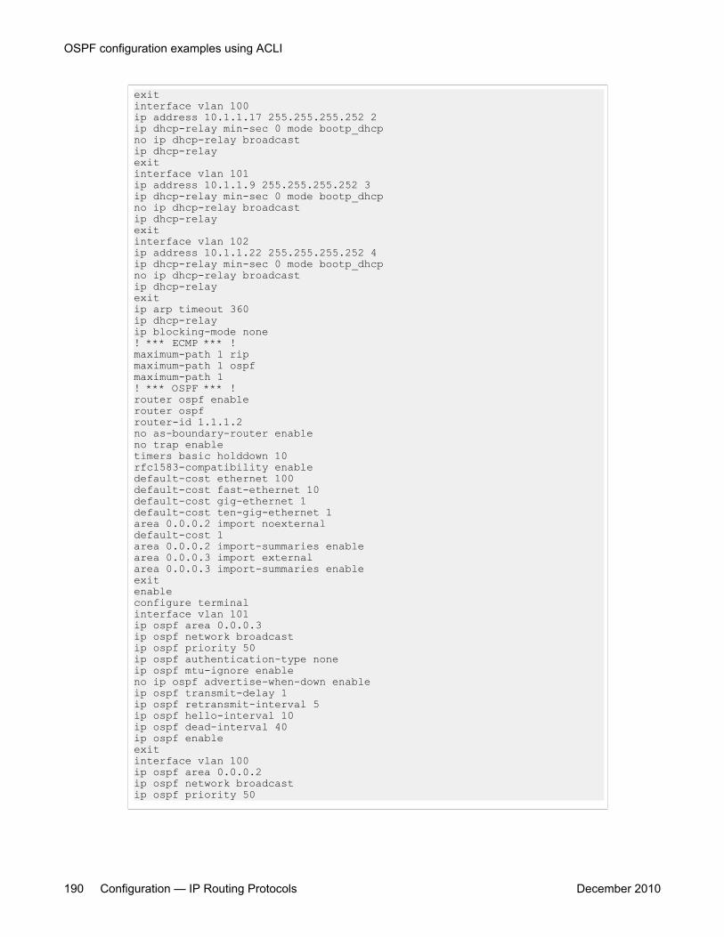
exitinterface vlan 100ip address 10.1.1.17 255.255.255.252 2ip dhcp-relay min-sec 0 mode bootp_dhcpno ip dhcp-relay broadcastip dhcp-relayexitinterface vlan 101ip address 10.1.1.9 255.255.255.252 3ip dhcp-relay min-sec 0 mode bootp_dhcpno ip dhcp-relay broadcastip dhcp-relayexitinterface vlan 102ip address 10.1.1.22 255.255.255.252 4ip dhcp-relay min-sec 0 mode bootp_dhcpno ip dhcp-relay broadcastip dhcp-relayexitip arp timeout 360ip dhcp-relayip blocking-mode none! *** ECMP *** !maximum-path 1 ripmaximum-path 1 ospfmaximum-path 1! *** OSPF *** !router ospf enablerouter ospfrouter-id 1.1.1.2no as-boundary-router enableno trap enabletimers basic holddown 10rfc1583-compatibility enabledefault-cost ethernet 100default-cost fast-ethernet 10default-cost gig-ethernet 1default-cost ten-gig-ethernet 1area 0.0.0.2 import noexternaldefault-cost 1area 0.0.0.2 import-summaries enablearea 0.0.0.3 import externalarea 0.0.0.3 import-summaries enableexitenableconfigure terminalinterface vlan 101ip ospf area 0.0.0.3ip ospf network broadcastip ospf priority 50ip ospf authentication-type noneip ospf mtu-ignore enableno ip ospf advertise-when-down enableip ospf transmit-delay 1ip ospf retransmit-interval 5ip ospf hello-interval 10ip ospf dead-interval 40ip ospf enableexitinterface vlan 100ip ospf area 0.0.0.2ip ospf network broadcastip ospf priority 50
OSPF configuration examples using ACLI
190 Configuration — IP Routing Protocols December 2010
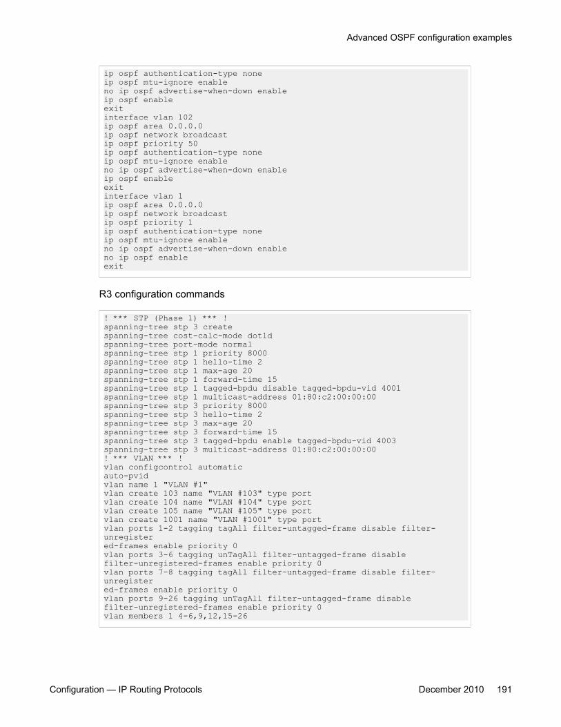
ip ospf authentication-type noneip ospf mtu-ignore enableno ip ospf advertise-when-down enableip ospf enableexitinterface vlan 102ip ospf area 0.0.0.0ip ospf network broadcastip ospf priority 50ip ospf authentication-type noneip ospf mtu-ignore enableno ip ospf advertise-when-down enableip ospf enableexitinterface vlan 1ip ospf area 0.0.0.0ip ospf network broadcastip ospf priority 1ip ospf authentication-type noneip ospf mtu-ignore enableno ip ospf advertise-when-down enableno ip ospf enableexit
R3 configuration commands
! *** STP (Phase 1) *** !spanning-tree stp 3 createspanning-tree cost-calc-mode dot1dspanning-tree port-mode normalspanning-tree stp 1 priority 8000spanning-tree stp 1 hello-time 2spanning-tree stp 1 max-age 20spanning-tree stp 1 forward-time 15spanning-tree stp 1 tagged-bpdu disable tagged-bpdu-vid 4001spanning-tree stp 1 multicast-address 01:80:c2:00:00:00spanning-tree stp 3 priority 8000spanning-tree stp 3 hello-time 2spanning-tree stp 3 max-age 20spanning-tree stp 3 forward-time 15spanning-tree stp 3 tagged-bpdu enable tagged-bpdu-vid 4003spanning-tree stp 3 multicast-address 01:80:c2:00:00:00! *** VLAN *** !vlan configcontrol automaticauto-pvidvlan name 1 "VLAN #1"vlan create 103 name "VLAN #103" type portvlan create 104 name "VLAN #104" type portvlan create 105 name "VLAN #105" type portvlan create 1001 name "VLAN #1001" type portvlan ports 1-2 tagging tagAll filter-untagged-frame disable filter-unregistered-frames enable priority 0vlan ports 3-6 tagging unTagAll filter-untagged-frame disablefilter-unregistered-frames enable priority 0vlan ports 7-8 tagging tagAll filter-untagged-frame disable filter-unregistered-frames enable priority 0vlan ports 9-26 tagging unTagAll filter-untagged-frame disablefilter-unregistered-frames enable priority 0vlan members 1 4-6,9,12,15-26
Advanced OSPF configuration examples
Configuration — IP Routing Protocols December 2010 191
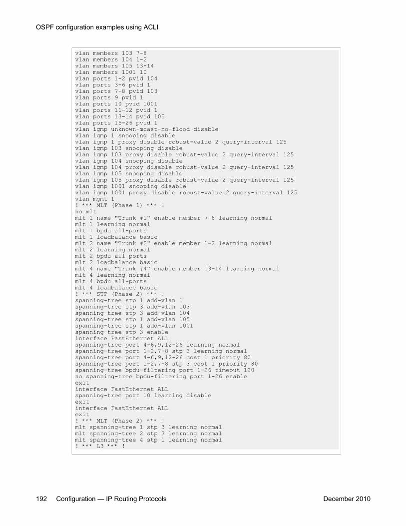
vlan members 103 7-8vlan members 104 1-2vlan members 105 13-14vlan members 1001 10vlan ports 1-2 pvid 104vlan ports 3-6 pvid 1vlan ports 7-8 pvid 103vlan ports 9 pvid 1vlan ports 10 pvid 1001vlan ports 11-12 pvid 1vlan ports 13-14 pvid 105vlan ports 15-26 pvid 1vlan igmp unknown-mcast-no-flood disablevlan igmp 1 snooping disablevlan igmp 1 proxy disable robust-value 2 query-interval 125vlan igmp 103 snooping disablevlan igmp 103 proxy disable robust-value 2 query-interval 125vlan igmp 104 snooping disablevlan igmp 104 proxy disable robust-value 2 query-interval 125vlan igmp 105 snooping disablevlan igmp 105 proxy disable robust-value 2 query-interval 125vlan igmp 1001 snooping disablevlan igmp 1001 proxy disable robust-value 2 query-interval 125vlan mgmt 1! *** MLT (Phase 1) *** !no mltmlt 1 name "Trunk #1" enable member 7-8 learning normalmlt 1 learning normalmlt 1 bpdu all-portsmlt 1 loadbalance basicmlt 2 name "Trunk #2" enable member 1-2 learning normalmlt 2 learning normalmlt 2 bpdu all-portsmlt 2 loadbalance basicmlt 4 name "Trunk #4" enable member 13-14 learning normalmlt 4 learning normalmlt 4 bpdu all-portsmlt 4 loadbalance basic! *** STP (Phase 2) *** !spanning-tree stp 1 add-vlan 1spanning-tree stp 3 add-vlan 103spanning-tree stp 3 add-vlan 104spanning-tree stp 1 add-vlan 105spanning-tree stp 1 add-vlan 1001spanning-tree stp 3 enableinterface FastEthernet ALLspanning-tree port 4-6,9,12-26 learning normalspanning-tree port 1-2,7-8 stp 3 learning normalspanning-tree port 4-6,9,12-26 cost 1 priority 80spanning-tree port 1-2,7-8 stp 3 cost 1 priority 80spanning-tree bpdu-filtering port 1-26 timeout 120no spanning-tree bpdu-filtering port 1-26 enableexitinterface FastEthernet ALLspanning-tree port 10 learning disableexitinterface FastEthernet ALLexit! *** MLT (Phase 2) *** !mlt spanning-tree 1 stp 3 learning normalmlt spanning-tree 2 stp 3 learning normalmlt spanning-tree 4 stp 1 learning normal! *** L3 *** !
OSPF configuration examples using ACLI
192 Configuration — IP Routing Protocols December 2010
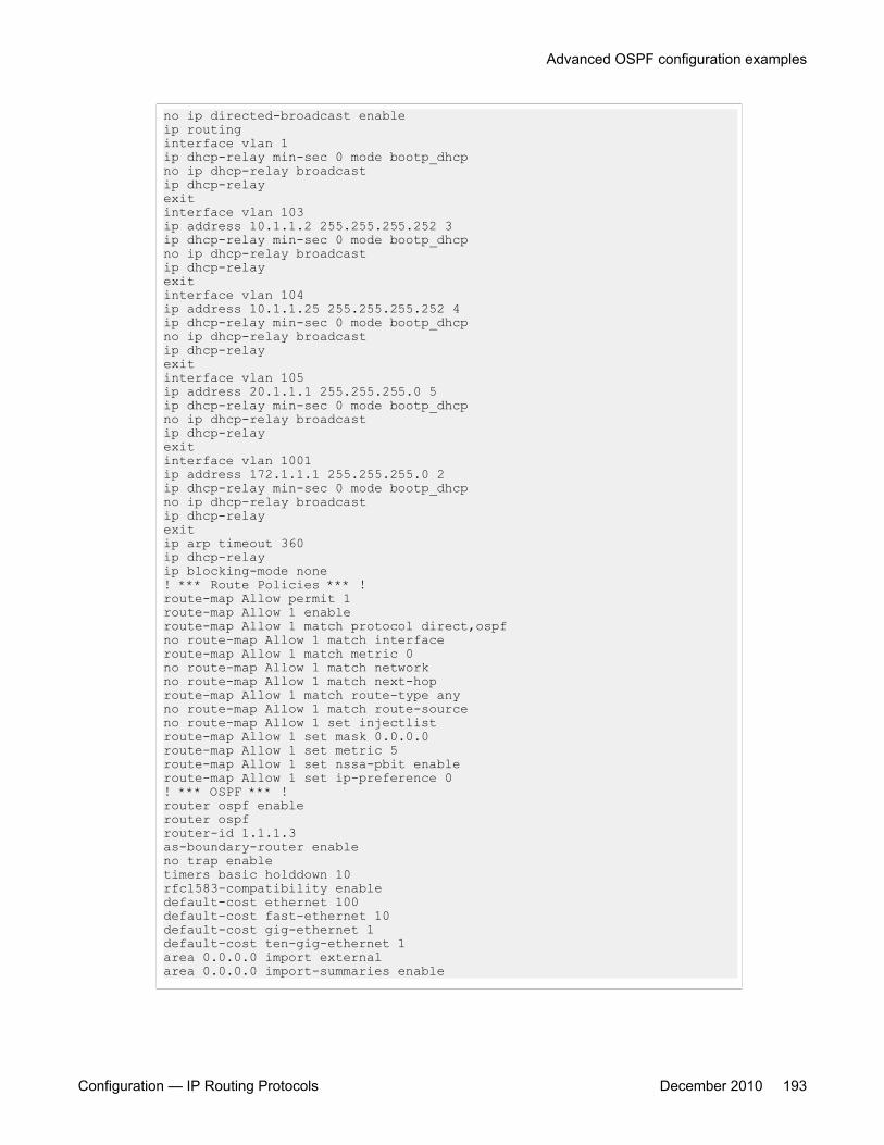
no ip directed-broadcast enableip routinginterface vlan 1ip dhcp-relay min-sec 0 mode bootp_dhcpno ip dhcp-relay broadcastip dhcp-relayexitinterface vlan 103ip address 10.1.1.2 255.255.255.252 3ip dhcp-relay min-sec 0 mode bootp_dhcpno ip dhcp-relay broadcastip dhcp-relayexitinterface vlan 104ip address 10.1.1.25 255.255.255.252 4ip dhcp-relay min-sec 0 mode bootp_dhcpno ip dhcp-relay broadcastip dhcp-relayexitinterface vlan 105ip address 20.1.1.1 255.255.255.0 5ip dhcp-relay min-sec 0 mode bootp_dhcpno ip dhcp-relay broadcastip dhcp-relayexitinterface vlan 1001ip address 172.1.1.1 255.255.255.0 2ip dhcp-relay min-sec 0 mode bootp_dhcpno ip dhcp-relay broadcastip dhcp-relayexitip arp timeout 360ip dhcp-relayip blocking-mode none! *** Route Policies *** !route-map Allow permit 1route-map Allow 1 enableroute-map Allow 1 match protocol direct,ospfno route-map Allow 1 match interfaceroute-map Allow 1 match metric 0no route-map Allow 1 match networkno route-map Allow 1 match next-hoproute-map Allow 1 match route-type anyno route-map Allow 1 match route-sourceno route-map Allow 1 set injectlistroute-map Allow 1 set mask 0.0.0.0route-map Allow 1 set metric 5route-map Allow 1 set nssa-pbit enableroute-map Allow 1 set ip-preference 0! *** OSPF *** !router ospf enablerouter ospfrouter-id 1.1.1.3as-boundary-router enableno trap enabletimers basic holddown 10rfc1583-compatibility enabledefault-cost ethernet 100default-cost fast-ethernet 10default-cost gig-ethernet 1default-cost ten-gig-ethernet 1area 0.0.0.0 import externalarea 0.0.0.0 import-summaries enable
Advanced OSPF configuration examples
Configuration — IP Routing Protocols December 2010 193

area 0.0.0.3 import externalarea 0.0.0.3 import-summaries enableredistribute direct metric 10 metric-type type2 subnets allowredistribute direct enableredistribute rip metric 10 metric-type type2 subnets allowredistribute rip enableexitenableconfigure terminalinterface vlan 103ip ospf area 0.0.0.3ip ospf network broadcastip ospf priority 1ip ospf authentication-type noneip ospf mtu-ignore enableno ip ospf advertise-when-down enableip ospf transmit-delay 1ip ospf retransmit-interval 5ip ospf hello-interval 10ip ospf dead-interval 40ip ospf enableexitinterface vlan 104ip ospf area 0.0.0.3ip ospf network broadcastip ospf priority 1ip ospf authentication-type noneip ospf mtu-ignore enableno ip ospf advertise-when-down enableip ospf enableexitinterface vlan 105ip ospf area 0.0.0.0ip ospf network broadcastip ospf priority 1ip ospf authentication-type noneip ospf mtu-ignore enableno ip ospf advertise-when-down enableno ip ospf enableexitinterface vlan 1001ip ospf area 0.0.0.3ip ospf network broadcastip ospf priority 1ip ospf authentication-type noneip ospf mtu-ignore enableno ip ospf advertise-when-down enableip ospf enableexitinterface vlan 1ip ospf area 0.0.0.0ip ospf network broadcastip ospf priority 1ip ospf authentication-type noneip ospf mtu-ignore enableno ip ospf advertise-when-down enableno ip ospf enableexit! *** RIP *** !router riprouter rip enabletimers basic holddown 120timers basic timeout 180 update 30
OSPF configuration examples using ACLI
194 Configuration — IP Routing Protocols December 2010
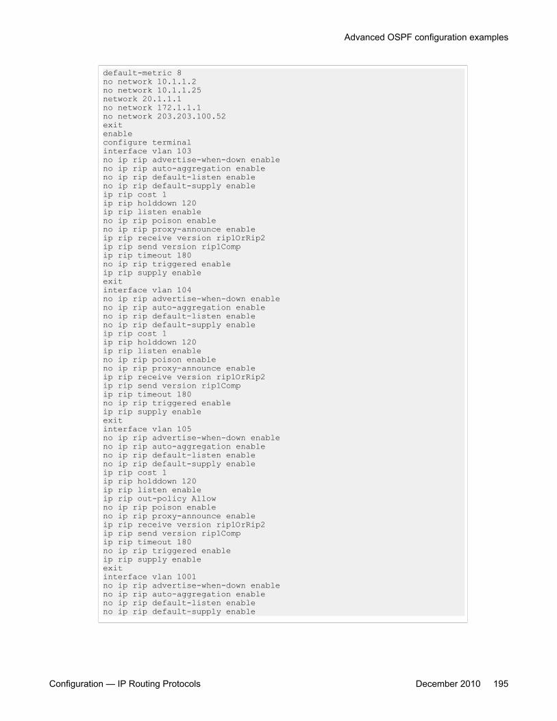
default-metric 8no network 10.1.1.2no network 10.1.1.25network 20.1.1.1no network 172.1.1.1no network 203.203.100.52exitenableconfigure terminalinterface vlan 103no ip rip advertise-when-down enableno ip rip auto-aggregation enableno ip rip default-listen enableno ip rip default-supply enableip rip cost 1ip rip holddown 120ip rip listen enableno ip rip poison enableno ip rip proxy-announce enableip rip receive version rip1OrRip2ip rip send version rip1Compip rip timeout 180no ip rip triggered enableip rip supply enableexitinterface vlan 104no ip rip advertise-when-down enableno ip rip auto-aggregation enableno ip rip default-listen enableno ip rip default-supply enableip rip cost 1ip rip holddown 120ip rip listen enableno ip rip poison enableno ip rip proxy-announce enableip rip receive version rip1OrRip2ip rip send version rip1Compip rip timeout 180no ip rip triggered enableip rip supply enableexitinterface vlan 105no ip rip advertise-when-down enableno ip rip auto-aggregation enableno ip rip default-listen enableno ip rip default-supply enableip rip cost 1ip rip holddown 120ip rip listen enableip rip out-policy Allowno ip rip poison enableno ip rip proxy-announce enableip rip receive version rip1OrRip2ip rip send version rip1Compip rip timeout 180no ip rip triggered enableip rip supply enableexitinterface vlan 1001no ip rip advertise-when-down enableno ip rip auto-aggregation enableno ip rip default-listen enableno ip rip default-supply enable
Advanced OSPF configuration examples
Configuration — IP Routing Protocols December 2010 195

ip rip cost 1ip rip holddown 120ip rip listen enableno ip rip poison enableno ip rip proxy-announce enableip rip receive version rip1OrRip2ip rip send version rip1Compip rip timeout 180no ip rip triggered enableip rip supply enableexitinterface vlan 1no ip rip advertise-when-down enableno ip rip auto-aggregation enableno ip rip default-listen enableno ip rip default-supply enableip rip cost 1ip rip holddown 120ip rip listen enableno ip rip poison enableno ip rip proxy-announce enableip rip receive version rip1OrRip2ip rip send version rip1Compip rip timeout 180no ip rip triggered enableip rip supplyenableexit
R4 configuration commands
! *** STP (Phase 1) *** !spanning-tree stp 3 createspanning-tree cost-calc-mode dot1dspanning-tree port-mode normalspanning-tree stp 1 priority 8000spanning-tree stp 1 hello-time 2spanning-tree stp 1 max-age 20spanning-tree stp 1 forward-time 15spanning-tree stp 1 tagged-bpdu disable tagged-bpdu-vid 4001spanning-tree stp 1 multicast-address 01:80:c2:00:00:00spanning-tree stp 3 priority 8000spanning-tree stp 3 hello-time 2spanning-tree stp 3 max-age 20spanning-tree stp 3 forward-time 15spanning-tree stp 3 tagged-bpdu enable tagged-bpdu-vid 4003spanning-tree stp 3 multicast-address 01:80:c2:00:00:00! *** VLAN *** !vlan configcontrol automaticauto-pvidvlan name 1 "VLAN #1"vlan create 101 name "VLAN #101" type portvlan create 104 name "VLAN #104" type portvlan ports 1-26 tagging unTagAll filter-untagged-frame disablefilter-unregistered-frames enable priority 0vlan members 1 3-6,9-26vlan members 101 7-8vlan members 104 1-2vlan ports 1-2 pvid 104vlan ports 3-6 pvid 1vlan ports 7-8 pvid 101
OSPF configuration examples using ACLI
196 Configuration — IP Routing Protocols December 2010
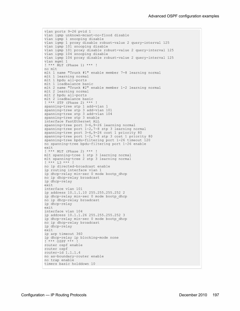
vlan ports 9-26 pvid 1vlan igmp unknown-mcast-no-flood disablevlan igmp 1 snooping disablevlan igmp 1 proxy disable robust-value 2 query-interval 125vlan igmp 101 snooping disablevlan igmp 101 proxy disable robust-value 2 query-interval 125vlan igmp 104 snooping disablevlan igmp 104 proxy disable robust-value 2 query-interval 125vlan mgmt 1! *** MLT (Phase 1) *** !no mltmlt 1 name "Trunk #1" enable member 7-8 learning normalmlt 1 learning normalmlt 1 bpdu all-portsmlt 1 loadbalance basicmlt 2 name "Trunk #2" enable member 1-2 learning normalmlt 2 learning normalmlt 2 bpdu all-portsmlt 2 loadbalance basic! *** STP (Phase 2) *** !spanning-tree stp 1 add-vlan 1spanning-tree stp 3 add-vlan 101spanning-tree stp 3 add-vlan 104spanning-tree stp 3 enableinterface FastEthernet ALLspanning-tree port 3-6,9-26 learning normalspanning-tree port 1-2,7-8 stp 3 learning normalspanning-tree port 3-6,9-26 cost 1 priority 80spanning-tree port 1-2,7-8 stp 3 cost 1 priority 80spanning-tree bpdu-filtering port 1-26 timeout 120no spanning-tree bpdu-filtering port 1-26 enableexit! *** MLT (Phase 2) *** !mlt spanning-tree 1 stp 3 learning normalmlt spanning-tree 2 stp 3 learning normal! *** L3 *** !no ip directed-broadcast enableip routing interface vlan 1ip dhcp-relay min-sec 0 mode bootp_dhcpno ip dhcp-relay broadcastip dhcp-relayexitinterface vlan 101ip address 10.1.1.10 255.255.255.252 2ip dhcp-relay min-sec 0 mode bootp_dhcpno ip dhcp-relay broadcastip dhcp-relayexitinterface vlan 104ip address 10.1.1.26 255.255.255.252 3ip dhcp-relay min-sec 0 mode bootp_dhcpno ip dhcp-relay broadcastip dhcp-relayexitip arp timeout 360ip dhcp-relay ip blocking-mode none! *** OSPF *** !router ospf enablerouter ospfrouter-id 1.1.1.4no as-boundary-router enableno trap enabletimers basic holddown 10
Advanced OSPF configuration examples
Configuration — IP Routing Protocols December 2010 197
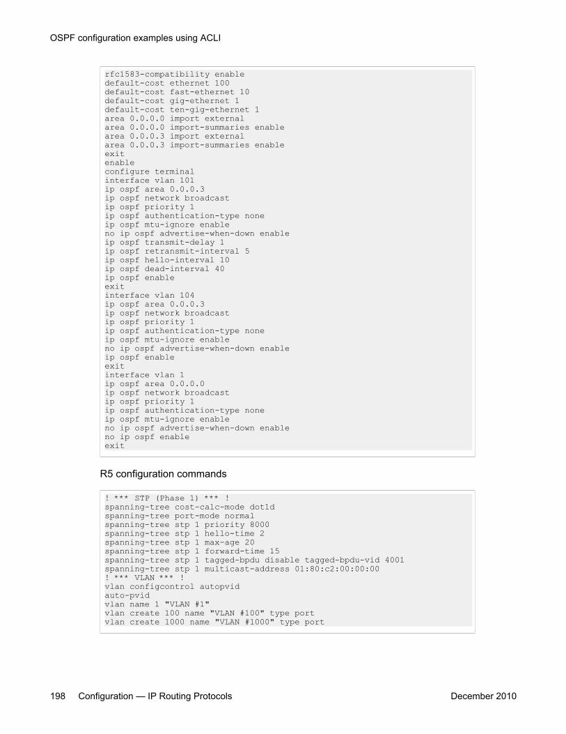
rfc1583-compatibility enabledefault-cost ethernet 100default-cost fast-ethernet 10default-cost gig-ethernet 1default-cost ten-gig-ethernet 1area 0.0.0.0 import externalarea 0.0.0.0 import-summaries enablearea 0.0.0.3 import externalarea 0.0.0.3 import-summaries enableexitenableconfigure terminalinterface vlan 101ip ospf area 0.0.0.3ip ospf network broadcastip ospf priority 1ip ospf authentication-type noneip ospf mtu-ignore enableno ip ospf advertise-when-down enableip ospf transmit-delay 1ip ospf retransmit-interval 5ip ospf hello-interval 10ip ospf dead-interval 40ip ospf enableexitinterface vlan 104ip ospf area 0.0.0.3ip ospf network broadcastip ospf priority 1ip ospf authentication-type noneip ospf mtu-ignore enableno ip ospf advertise-when-down enableip ospf enableexitinterface vlan 1ip ospf area 0.0.0.0ip ospf network broadcastip ospf priority 1ip ospf authentication-type noneip ospf mtu-ignore enableno ip ospf advertise-when-down enableno ip ospf enableexit
R5 configuration commands
! *** STP (Phase 1) *** !spanning-tree cost-calc-mode dot1dspanning-tree port-mode normalspanning-tree stp 1 priority 8000spanning-tree stp 1 hello-time 2spanning-tree stp 1 max-age 20spanning-tree stp 1 forward-time 15spanning-tree stp 1 tagged-bpdu disable tagged-bpdu-vid 4001spanning-tree stp 1 multicast-address 01:80:c2:00:00:00! *** VLAN *** !vlan configcontrol autopvidauto-pvidvlan name 1 "VLAN #1"vlan create 100 name "VLAN #100" type portvlan create 1000 name "VLAN #1000" type port
OSPF configuration examples using ACLI
198 Configuration — IP Routing Protocols December 2010
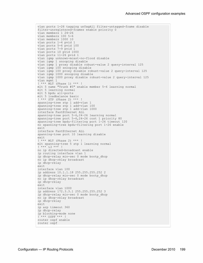
vlan ports 1-26 tagging unTagAll filter-untagged-frame disablefilter-unregistered-frames enable priority 0vlan members 1 24-26vlan members 100 5-6vlan members 1000 10vlan ports 1-4 pvid 1vlan ports 5-6 pvid 100vlan ports 7-9 pvid 1vlan ports 10 pvid 1000vlan ports 11-26 pvid 1vlan igmp unknown-mcast-no-flood disablevlan igmp 1 snooping disablevlan igmp 1 proxy disable robust-value 2 query-interval 125vlan igmp 100 snooping disablevlan igmp 100 proxy disable robust-value 2 query-interval 125vlan igmp 1000 snooping disablevlan igmp 1000 proxy disable robust-value 2 query-interval 125vlan mgmt 1! *** MLT (Phase 1) *** !mlt 5 name "Trunk #5" enable member 5-6 learning normalmlt 5 learning normalmlt 5 bpdu all-portsmlt 5 loadbalance basic! *** STP (Phase 2) *** !spanning-tree stp 1 add-vlan 1spanning-tree stp 1 add-vlan 100spanning-tree stp 1 add-vlan 1000interface FastEthernet ALLspanning-tree port 5-6,24-26 learning normalspanning-tree port 5-6,24-26 cost 1 priority 80spanning-tree bpdu-filtering port 1-26 timeout 120no spanning-tree bpdu-filtering port 1-26 enableexitinterface FastEthernet ALLspanning-tree port 10 learning disableexit! *** MLT (Phase 2) *** !mlt spanning-tree 5 stp 1 learning normal! *** L3 *** !no ip directed-broadcast enableip routing interface vlan 1ip dhcp-relay min-sec 0 mode bootp_dhcpno ip dhcp-relay broadcastip dhcp-relayexitinterface vlan 100ip address 10.1.1.18 255.255.255.252 2ip dhcp-relay min-sec 0 mode bootp_dhcpno ip dhcp-relay broadcastip dhcp-relayexitinterface vlan 1000ip address 172.3.3.1 255.255.255.252 3ip dhcp-relay min-sec 0 mode bootp_dhcpno ip dhcp-relay broadcastip dhcp-relayexitip arp timeout 360ip dhcp-relayip blocking-mode none! *** OSPF *** !router ospf enablerouter ospf
Advanced OSPF configuration examples
Configuration — IP Routing Protocols December 2010 199
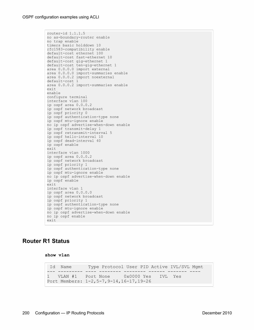
router-id 1.1.1.5no as-boundary-router enableno trap enabletimers basic holddown 10rfc1583-compatibility enabledefault-cost ethernet 100default-cost fast-ethernet 10default-cost gig-ethernet 1default-cost ten-gig-ethernet 1area 0.0.0.0 import externalarea 0.0.0.0 import-summaries enablearea 0.0.0.2 import noexternaldefault-cost 1area 0.0.0.2 import-summaries enableexitenableconfigure terminalinterface vlan 100ip ospf area 0.0.0.2ip ospf network broadcastip ospf priority 0ip ospf authentication-type noneip ospf mtu-ignore enableno ip ospf advertise-when-down enableip ospf transmit-delay 1ip ospf retransmit-interval 5ip ospf hello-interval 10ip ospf dead-interval 40ip ospf enableexitinterface vlan 1000ip ospf area 0.0.0.2ip ospf network broadcastip ospf priority 1ip ospf authentication-type noneip ospf mtu-ignore enableno ip ospf advertise-when-down enableip ospf enableexitinterface vlan 1ip ospf area 0.0.0.0ip ospf network broadcastip ospf priority 1ip ospf authentication-type noneip ospf mtu-ignore enableno ip ospf advertise-when-down enableno ip ospf enableexit
Router R1 Status
show vlan
Id Name Type Protocol User PID Active IVL/SVL Mgmt --- --------- ---- -------- -------- ------ ------- ---- 1 VLAN #1 Port None 0x0000 Yes IVL Yes Port Members: 1-2,5-7,9-14,16-17,19-26
OSPF configuration examples using ACLI
200 Configuration — IP Routing Protocols December 2010
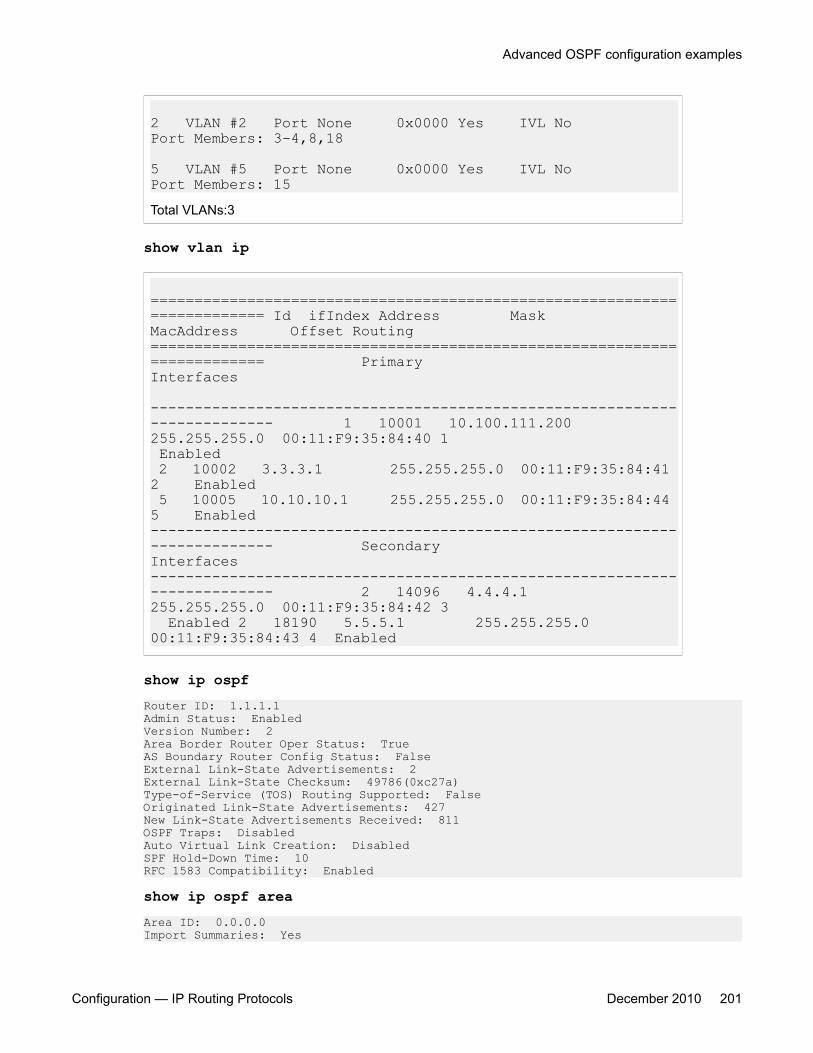
2 VLAN #2 Port None 0x0000 Yes IVL No Port Members: 3-4,8,18
5 VLAN #5 Port None 0x0000 Yes IVL No Port Members: 15Total VLANs:3
show vlan ip
========================================================================= Id ifIndex Address Mask MacAddress Offset Routing ========================================================================= Primary Interfaces -------------------------------------------------------------------------- 1 10001 10.100.111.200 255.255.255.0 00:11:F9:35:84:40 1 Enabled 2 10002 3.3.3.1 255.255.255.0 00:11:F9:35:84:41 2 Enabled 5 10005 10.10.10.1 255.255.255.0 00:11:F9:35:84:44 5 Enabled -------------------------------------------------------------------------- Secondary Interfaces -------------------------------------------------------------------------- 2 14096 4.4.4.1 255.255.255.0 00:11:F9:35:84:42 3 Enabled 2 18190 5.5.5.1 255.255.255.0 00:11:F9:35:84:43 4 Enabled
show ip ospfRouter ID: 1.1.1.1 Admin Status: EnabledVersion Number: 2Area Border Router Oper Status: True AS Boundary Router Config Status: False External Link-State Advertisements: 2 External Link-State Checksum: 49786(0xc27a) Type-of-Service (TOS) Routing Supported: False Originated Link-State Advertisements: 427 New Link-State Advertisements Received: 811 OSPF Traps: Disabled Auto Virtual Link Creation: Disabled SPF Hold-Down Time: 10 RFC 1583 Compatibility: Enabled
show ip ospf areaArea ID: 0.0.0.0Import Summaries: Yes
Advanced OSPF configuration examples
Configuration — IP Routing Protocols December 2010 201
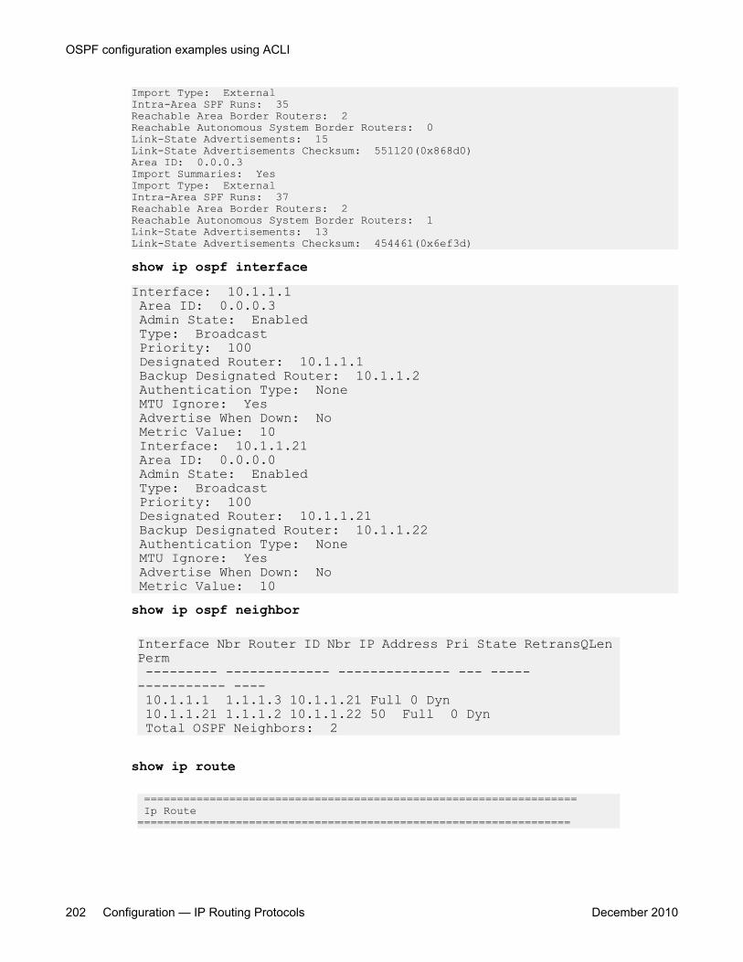
Import Type: ExternalIntra-Area SPF Runs: 35Reachable Area Border Routers: 2Reachable Autonomous System Border Routers: 0Link-State Advertisements: 15Link-State Advertisements Checksum: 551120(0x868d0)Area ID: 0.0.0.3Import Summaries: YesImport Type: ExternalIntra-Area SPF Runs: 37Reachable Area Border Routers: 2Reachable Autonomous System Border Routers: 1Link-State Advertisements: 13Link-State Advertisements Checksum: 454461(0x6ef3d)
show ip ospf interfaceInterface: 10.1.1.1 Area ID: 0.0.0.3 Admin State: Enabled Type: Broadcast Priority: 100 Designated Router: 10.1.1.1 Backup Designated Router: 10.1.1.2 Authentication Type: None MTU Ignore: Yes Advertise When Down: No Metric Value: 10 Interface: 10.1.1.21 Area ID: 0.0.0.0 Admin State: Enabled Type: Broadcast Priority: 100 Designated Router: 10.1.1.21 Backup Designated Router: 10.1.1.22 Authentication Type: None MTU Ignore: Yes Advertise When Down: No Metric Value: 10show ip ospf neighbor
Interface Nbr Router ID Nbr IP Address Pri State RetransQLen Perm --------- ------------- -------------- --- ----- ----------- ---- 10.1.1.1 1.1.1.3 10.1.1.21 Full 0 Dyn 10.1.1.21 1.1.1.2 10.1.1.22 50 Full 0 Dyn Total OSPF Neighbors: 2
show ip route
================================================================== Ip Route ==================================================================
OSPF configuration examples using ACLI
202 Configuration — IP Routing Protocols December 2010
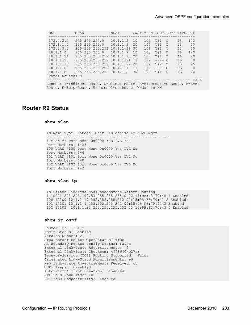
DST MASK NEXT COST VLAN PORT PROT TYPE PRF ------------------------------------------------------------------ 172.2.2.0 255.255.255.0 10.1.1.2 10 103 T#1 O IB 120 172.1.1.0 255.255.255.0 10.1.1.2 20 103 T#1 O IB 20 172.3.3.0 255.255.255.252 10.1.1.22 30 102 T#2 O IB 25 20.1.1.0 255.255.255.0 10.1.1.2 10 103 T#1 O IB 120 10.1.1.24 255.255.255.252 10.1.1.2 20 103 T#1 O IB 20 10.1.1.20 255.255.255.252 10.1.1.21 1 102 ---- C DB 0 10.1.1.16 255.255.255.252 10.1.1.22 20 102 T#2 O IB 25 10.1.1.0 255.255.255.252 10.1.1.1 1 103 ---- C DB 0 10.1.1.8 255.255.255.252 10.1.1.2 30 103 T#1 O IB 20 Total Routes: 9 ----------------------------------------------------------------- TYPE Legend: I=Indirect Route, D=Direct Route, A=Alternative Route, B=Best Route, E=Ecmp Route, U=Unresolved Route, N=Not in HW
Router R2 Status
show vlan
Id Name Type Protocol User PID Active IVL/SVL Mgmt--- --------- ---- -------- -------- ------ ------- ----1 VLAN #1 Port None 0x0000 Yes IVL YesPort Members: 1-26100 VLAN #100 Port None 0x0000 Yes IVL NoPort Members: 5-6101 VLAN #101 Port None 0x0000 Yes IVL NoPort Members: 7-8102 VLAN #102 Port None 0x0000 Yes IVL NoPort Members: 1-2
show vlan ip
Id ifIndex Address Mask MacAddress Offset Routing1 10001 203.203.100.53 255.255.255.0 00:15:9B:F3:70:40 1 Enabled100 10100 10.1.1.17 255.255.255.252 00:15:9B:F3:70:41 2 Enabled101 10101 10.1.1.9 255.255.255.252 00:15:9B:F3:70:42 3 Enabled102 10102 10.1.1.22 255.255.255.252 00:15:9B:F3:70:43 4 Enabled
show ip ospfRouter ID: 1.1.1.2Admin Status: EnabledVersion Number: 2Area Border Router Oper Status: TrueAS Boundary Router Config Status: FalseExternal Link-State Advertisements: 2External Link-State Checksum: 49786(0xc27a)Type-of-Service (TOS) Routing Supported: FalseOriginated Link-State Advertisements: 99New Link-State Advertisements Received: 66OSPF Traps: DisabledAuto Virtual Link Creation: DisabledSPF Hold-Down Time: 10RFC 1583 Compatibility: Enabled
Advanced OSPF configuration examples
Configuration — IP Routing Protocols December 2010 203
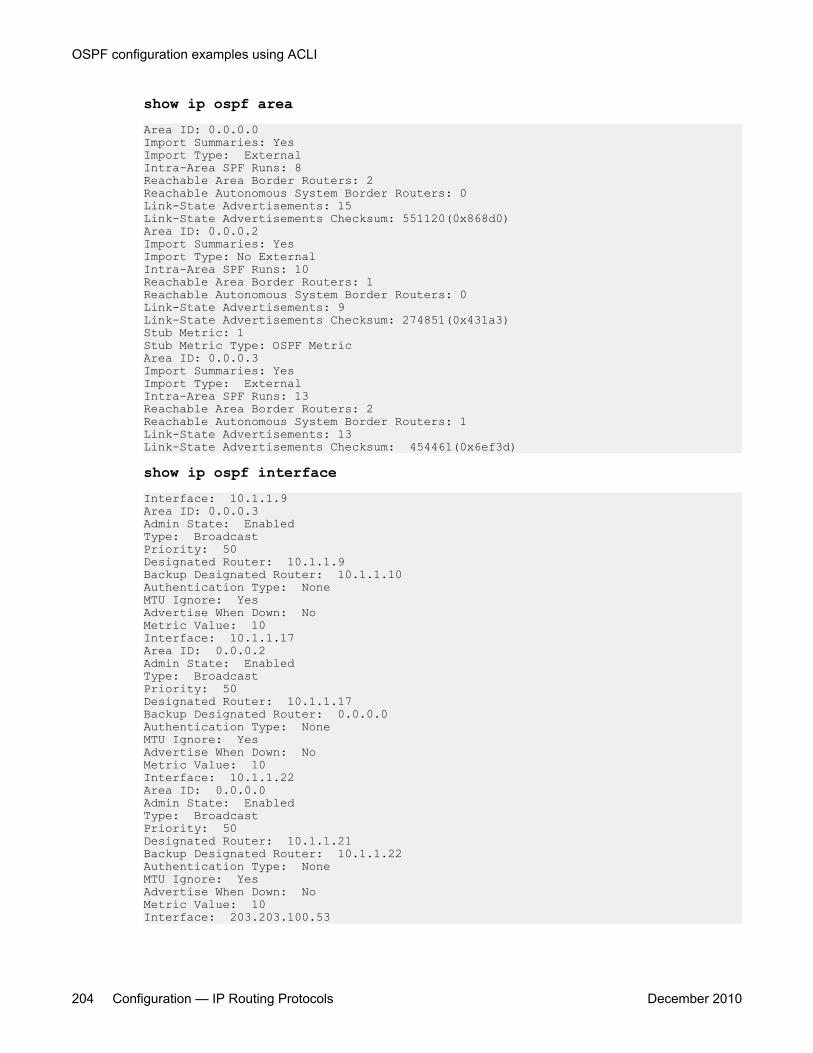
show ip ospf areaArea ID: 0.0.0.0Import Summaries: YesImport Type: ExternalIntra-Area SPF Runs: 8Reachable Area Border Routers: 2Reachable Autonomous System Border Routers: 0Link-State Advertisements: 15Link-State Advertisements Checksum: 551120(0x868d0)Area ID: 0.0.0.2Import Summaries: YesImport Type: No ExternalIntra-Area SPF Runs: 10Reachable Area Border Routers: 1Reachable Autonomous System Border Routers: 0Link-State Advertisements: 9Link-State Advertisements Checksum: 274851(0x431a3)Stub Metric: 1Stub Metric Type: OSPF MetricArea ID: 0.0.0.3Import Summaries: YesImport Type: ExternalIntra-Area SPF Runs: 13Reachable Area Border Routers: 2Reachable Autonomous System Border Routers: 1Link-State Advertisements: 13Link-State Advertisements Checksum: 454461(0x6ef3d)
show ip ospf interfaceInterface: 10.1.1.9Area ID: 0.0.0.3Admin State: EnabledType: BroadcastPriority: 50Designated Router: 10.1.1.9Backup Designated Router: 10.1.1.10Authentication Type: NoneMTU Ignore: YesAdvertise When Down: NoMetric Value: 10Interface: 10.1.1.17Area ID: 0.0.0.2Admin State: EnabledType: BroadcastPriority: 50Designated Router: 10.1.1.17Backup Designated Router: 0.0.0.0Authentication Type: NoneMTU Ignore: YesAdvertise When Down: NoMetric Value: 10Interface: 10.1.1.22Area ID: 0.0.0.0Admin State: EnabledType: BroadcastPriority: 50Designated Router: 10.1.1.21Backup Designated Router: 10.1.1.22Authentication Type: NoneMTU Ignore: YesAdvertise When Down: NoMetric Value: 10Interface: 203.203.100.53
OSPF configuration examples using ACLI
204 Configuration — IP Routing Protocols December 2010
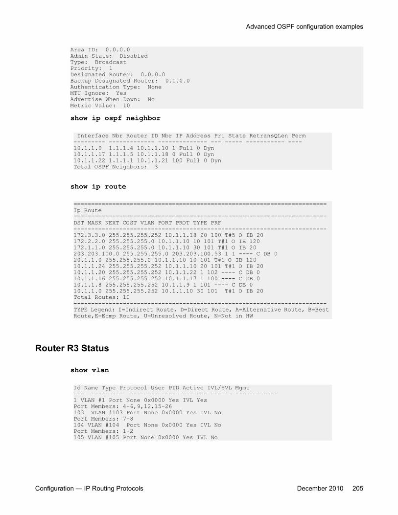
Area ID: 0.0.0.0Admin State: DisabledType: BroadcastPriority: 1Designated Router: 0.0.0.0Backup Designated Router: 0.0.0.0Authentication Type: NoneMTU Ignore: YesAdvertise When Down: NoMetric Value: 10
show ip ospf neighbor
Interface Nbr Router ID Nbr IP Address Pri State RetransQLen Perm--------- ------------- -------------- --- ----- ----------- ----10.1.1.9 1.1.1.4 10.1.1.10 1 Full 0 Dyn10.1.1.17 1.1.1.5 10.1.1.18 0 Full 0 Dyn10.1.1.22 1.1.1.1 10.1.1.21 100 Full 0 DynTotal OSPF Neighbors: 3
show ip route
========================================================================Ip Route========================================================================DST MASK NEXT COST VLAN PORT PROT TYPE PRF------------------------------------------------------------------------172.3.3.0 255.255.255.252 10.1.1.18 20 100 T#5 O IB 20172.2.2.0 255.255.255.0 10.1.1.10 10 101 T#1 O IB 120172.1.1.0 255.255.255.0 10.1.1.10 30 101 T#1 O IB 20203.203.100.0 255.255.255.0 203.203.100.53 1 1 ---- C DB 020.1.1.0 255.255.255.0 10.1.1.10 10 101 T#1 O IB 12010.1.1.24 255.255.255.252 10.1.1.10 20 101 T#1 O IB 2010.1.1.20 255.255.255.252 10.1.1.22 1 102 ---- C DB 010.1.1.16 255.255.255.252 10.1.1.17 1 100 ---- C DB 010.1.1.8 255.255.255.252 10.1.1.9 1 101 ---- C DB 010.1.1.0 255.255.255.252 10.1.1.10 30 101 T#1 O IB 20Total Routes: 10------------------------------------------------------------------------TYPE Legend: I=Indirect Route, D=Direct Route, A=Alternative Route, B=Best Route,E=Ecmp Route, U=Unresolved Route, N=Not in HW
Router R3 Status
show vlan
Id Name Type Protocol User PID Active IVL/SVL Mgmt--- --------- ---- -------- -------- ------ ------- ----1 VLAN #1 Port None 0x0000 Yes IVL YesPort Members: 4-6,9,12,15-26103 VLAN #103 Port None 0x0000 Yes IVL NoPort Members: 7-8104 VLAN #104 Port None 0x0000 Yes IVL NoPort Members: 1-2105 VLAN #105 Port None 0x0000 Yes IVL No
Advanced OSPF configuration examples
Configuration — IP Routing Protocols December 2010 205
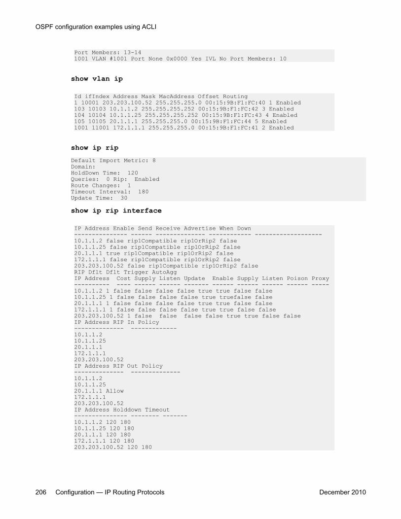
Port Members: 13-141001 VLAN #1001 Port None 0x0000 Yes IVL No Port Members: 10
show vlan ip
Id ifIndex Address Mask MacAddress Offset Routing1 10001 203.203.100.52 255.255.255.0 00:15:9B:F1:FC:40 1 Enabled103 10103 10.1.1.2 255.255.255.252 00:15:9B:F1:FC:42 3 Enabled104 10104 10.1.1.25 255.255.255.252 00:15:9B:F1:FC:43 4 Enabled105 10105 20.1.1.1 255.255.255.0 00:15:9B:F1:FC:44 5 Enabled 1001 11001 172.1.1.1 255.255.255.0 00:15:9B:F1:FC:41 2 Enabled
show ip ripDefault Import Metric: 8Domain:HoldDown Time: 120Queries: 0 Rip: EnabledRoute Changes: 1Timeout Interval: 180Update Time: 30
show ip rip interface
IP Address Enable Send Receive Advertise When Down--------------- ------ -------------- ------------ -------------------10.1.1.2 false rip1Compatible rip1OrRip2 false10.1.1.25 false rip1Compatible rip1OrRip2 false20.1.1.1 true rip1Compatible rip1OrRip2 false172.1.1.1 false rip1Compatible rip1OrRip2 false203.203.100.52 false rip1Compatible rip1OrRip2 falseRIP Dflt Dflt Trigger AutoAggIP Address Cost Supply Listen Update Enable Supply Listen Poison Proxy---------- ---- ------ ------ ------- ------ ------ ------ ------ -----10.1.1.2 1 false false false false true true false false10.1.1.25 1 false false false false true truefalse false20.1.1.1 1 false false false false true true false false172.1.1.1 1 false false false false true true false false203.203.100.52 1 false false false false true true false falseIP Address RIP In Policy-------------- -------------10.1.1.210.1.1.2520.1.1.1172.1.1.1203.203.100.52IP Address RIP Out Policy-------------- --------------10.1.1.210.1.1.2520.1.1.1 Allow172.1.1.1203.203.100.52IP Address Holddown Timeout--------------- -------- -------10.1.1.2 120 18010.1.1.25 120 18020.1.1.1 120 180172.1.1.1 120 180203.203.100.52 120 180
OSPF configuration examples using ACLI
206 Configuration — IP Routing Protocols December 2010
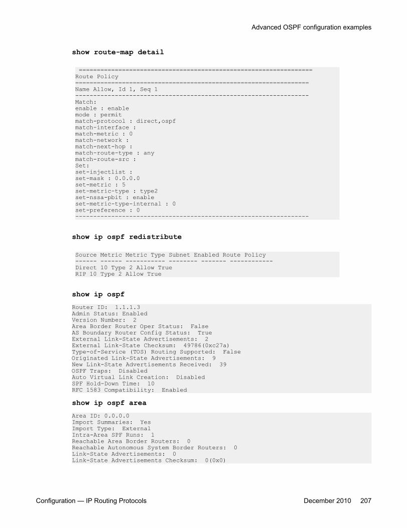
show route-map detail
=================================================================Route Policy =================================================================Name Allow, Id 1, Seq 1 -----------------------------------------------------------------Match:enable : enablemode : permitmatch-protocol : direct,ospfmatch-interface :match-metric : 0match-network :match-next-hop :match-route-type : anymatch-route-src :Set:set-injectlist :set-mask : 0.0.0.0set-metric : 5set-metric-type : type2set-nssa-pbit : enableset-metric-type-internal : 0set-preference : 0-----------------------------------------------------------------
show ip ospf redistribute
Source Metric Metric Type Subnet Enabled Route Policy------ ------ ----------- -------- ------- ------------Direct 10 Type 2 Allow TrueRIP 10 Type 2 Allow True
show ip ospfRouter ID: 1.1.1.3Admin Status: EnabledVersion Number: 2Area Border Router Oper Status: FalseAS Boundary Router Config Status: TrueExternal Link-State Advertisements: 2External Link-State Checksum: 49786(0xc27a)Type-of-Service (TOS) Routing Supported: FalseOriginated Link-State Advertisements: 9New Link-State Advertisements Received: 39OSPF Traps: DisabledAuto Virtual Link Creation: DisabledSPF Hold-Down Time: 10RFC 1583 Compatibility: Enabled
show ip ospf areaArea ID: 0.0.0.0Import Summaries: YesImport Type: ExternalIntra-Area SPF Runs: 1Reachable Area Border Routers: 0Reachable Autonomous System Border Routers: 0Link-State Advertisements: 0Link-State Advertisements Checksum: 0(0x0)
Advanced OSPF configuration examples
Configuration — IP Routing Protocols December 2010 207

Area ID: 0.0.0.3Import Summaries: YesImport Type: ExternalIntra-Area SPF Runs: 4Reachable Area Border Routers: 2Reachable Autonomous System Border Routers: 1Link-State Advertisements: 13Link-State Advertisements Checksum: 448840(0x6d948)
show ip ospfInterface: 10.1.1.2Area ID: 0.0.0.3Admin State: EnabledType: BroadcastPriority: 1Designated Router: 10.1.1.1Backup Designated Router: 10.1.1.2Authentication Type: NoneMTU Ignore: YesAdvertise When Down: NoMetric Value: 10Interface: 10.1.1.25Area ID: 0.0.0.3Admin State: EnabledType: BroadcastPriority: 1Designated Router: 10.1.1.26Backup Designated Router: 10.1.1.25Authentication Type: NoneMTU Ignore: YesAdvertise When Down: NoMetric Value: 10Interface: 20.1.1.1Area ID: 0.0.0.0Admin State: DisabledType: BroadcastPriority: 1Designated Router: 0.0.0.0Backup Designated Router: 0.0.0.0Authentication Type: NoneMTU Ignore: YesAdvertise When Down: NoMetric Value: 10Interface: 172.1.1.1Area ID: 0.0.0.3Admin State: EnabledType: BroadcastPriority: 1Designated Router: 172.1.1.1Backup Designated Router: 0.0.0.0Authentication Type: NoneMTU Ignore: YesAdvertise When Down: NoMetric Value: 10Interface: 203.203.100.52Area ID: 0.0.0.0Admin State: DisabledType: BroadcastPriority: 1Designated Router: 0.0.0.0Backup Designated Router: 0.0.0.0Authentication Type: NoneMTU Ignore: Yes
OSPF configuration examples using ACLI
208 Configuration — IP Routing Protocols December 2010
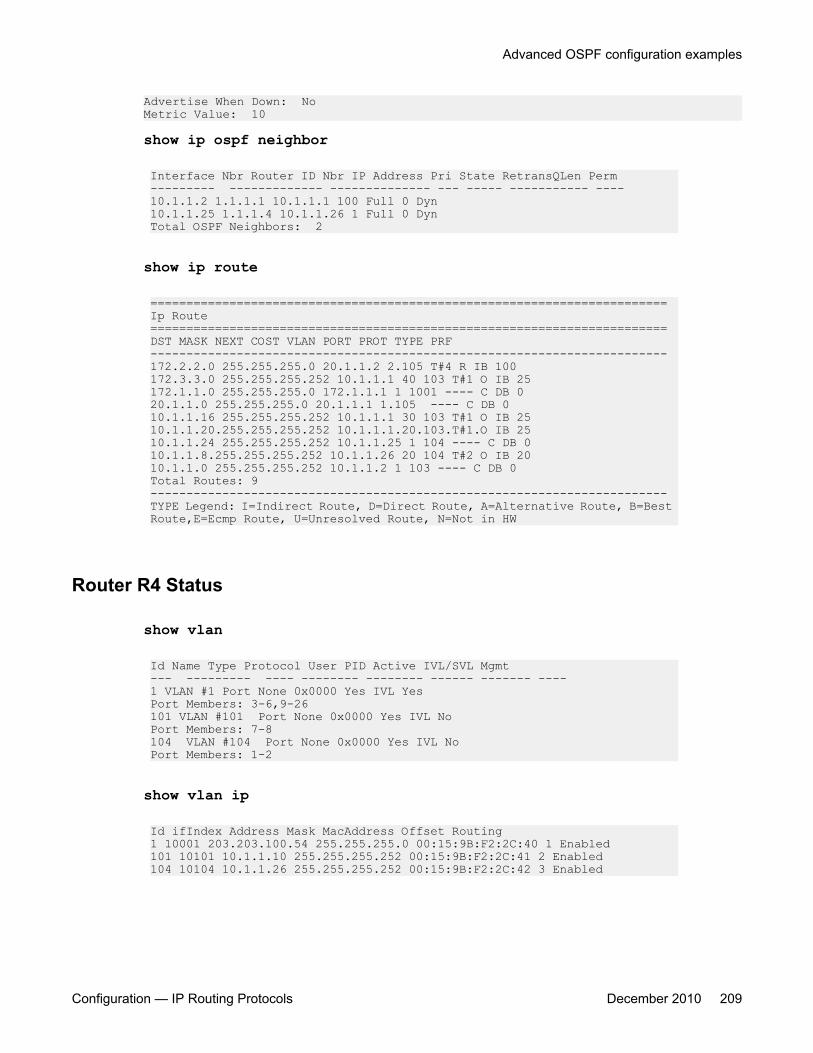
Advertise When Down: NoMetric Value: 10
show ip ospf neighbor
Interface Nbr Router ID Nbr IP Address Pri State RetransQLen Perm--------- ------------- -------------- --- ----- ----------- ----10.1.1.2 1.1.1.1 10.1.1.1 100 Full 0 Dyn10.1.1.25 1.1.1.4 10.1.1.26 1 Full 0 DynTotal OSPF Neighbors: 2
show ip route
========================================================================Ip Route========================================================================DST MASK NEXT COST VLAN PORT PROT TYPE PRF------------------------------------------------------------------------172.2.2.0 255.255.255.0 20.1.1.2 2.105 T#4 R IB 100172.3.3.0 255.255.255.252 10.1.1.1 40 103 T#1 O IB 25172.1.1.0 255.255.255.0 172.1.1.1 1 1001 ---- C DB 020.1.1.0 255.255.255.0 20.1.1.1 1.105 ---- C DB 010.1.1.16 255.255.255.252 10.1.1.1 30 103 T#1 O IB 2510.1.1.20.255.255.255.252 10.1.1.1.20.103.T#1.O IB 2510.1.1.24 255.255.255.252 10.1.1.25 1 104 ---- C DB 010.1.1.8.255.255.255.252 10.1.1.26 20 104 T#2 O IB 2010.1.1.0 255.255.255.252 10.1.1.2 1 103 ---- C DB 0Total Routes: 9------------------------------------------------------------------------TYPE Legend: I=Indirect Route, D=Direct Route, A=Alternative Route, B=Best Route,E=Ecmp Route, U=Unresolved Route, N=Not in HW
Router R4 Status
show vlan
Id Name Type Protocol User PID Active IVL/SVL Mgmt--- --------- ---- -------- -------- ------ ------- ----1 VLAN #1 Port None 0x0000 Yes IVL YesPort Members: 3-6,9-26101 VLAN #101 Port None 0x0000 Yes IVL NoPort Members: 7-8104 VLAN #104 Port None 0x0000 Yes IVL NoPort Members: 1-2
show vlan ip
Id ifIndex Address Mask MacAddress Offset Routing1 10001 203.203.100.54 255.255.255.0 00:15:9B:F2:2C:40 1 Enabled101 10101 10.1.1.10 255.255.255.252 00:15:9B:F2:2C:41 2 Enabled104 10104 10.1.1.26 255.255.255.252 00:15:9B:F2:2C:42 3 Enabled
Advanced OSPF configuration examples
Configuration — IP Routing Protocols December 2010 209
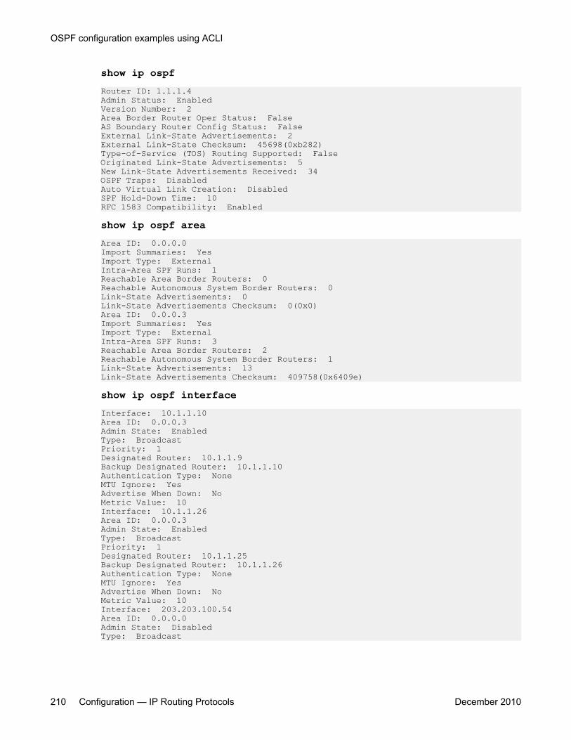
show ip ospfRouter ID: 1.1.1.4Admin Status: EnabledVersion Number: 2Area Border Router Oper Status: FalseAS Boundary Router Config Status: FalseExternal Link-State Advertisements: 2External Link-State Checksum: 45698(0xb282)Type-of-Service (TOS) Routing Supported: FalseOriginated Link-State Advertisements: 5New Link-State Advertisements Received: 34OSPF Traps: DisabledAuto Virtual Link Creation: DisabledSPF Hold-Down Time: 10RFC 1583 Compatibility: Enabled
show ip ospf areaArea ID: 0.0.0.0Import Summaries: YesImport Type: ExternalIntra-Area SPF Runs: 1Reachable Area Border Routers: 0Reachable Autonomous System Border Routers: 0Link-State Advertisements: 0Link-State Advertisements Checksum: 0(0x0)Area ID: 0.0.0.3Import Summaries: YesImport Type: ExternalIntra-Area SPF Runs: 3Reachable Area Border Routers: 2Reachable Autonomous System Border Routers: 1Link-State Advertisements: 13Link-State Advertisements Checksum: 409758(0x6409e)
show ip ospf interfaceInterface: 10.1.1.10Area ID: 0.0.0.3Admin State: EnabledType: BroadcastPriority: 1Designated Router: 10.1.1.9Backup Designated Router: 10.1.1.10Authentication Type: NoneMTU Ignore: YesAdvertise When Down: NoMetric Value: 10Interface: 10.1.1.26Area ID: 0.0.0.3Admin State: EnabledType: BroadcastPriority: 1Designated Router: 10.1.1.25Backup Designated Router: 10.1.1.26Authentication Type: NoneMTU Ignore: YesAdvertise When Down: NoMetric Value: 10Interface: 203.203.100.54Area ID: 0.0.0.0Admin State: DisabledType: Broadcast
OSPF configuration examples using ACLI
210 Configuration — IP Routing Protocols December 2010
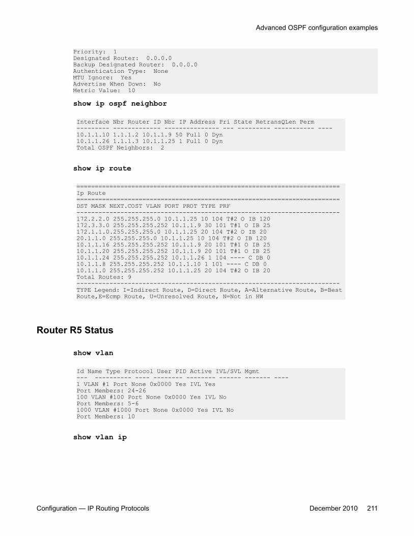
Priority: 1Designated Router: 0.0.0.0Backup Designated Router: 0.0.0.0Authentication Type: NoneMTU Ignore: YesAdvertise When Down: NoMetric Value: 10
show ip ospf neighbor
Interface Nbr Router ID Nbr IP Address Pri State RetransQLen Perm--------- ------------- --------------- --- --------- ----------- ----10.1.1.10 1.1.1.2 10.1.1.9 50 Full 0 Dyn10.1.1.26 1.1.1.3 10.1.1.25 1 Full 0 DynTotal OSPF Neighbors: 2
show ip route
========================================================================Ip Route========================================================================DST MASK NEXT.COST VLAN PORT PROT TYPE PRF------------------------------------------------------------------------172.2.2.0 255.255.255.0 10.1.1.25 10 104 T#2 O IB 120172.3.3.0 255.255.255.252 10.1.1.9 30 101 T#1 O IB 25172.1.1.0.255.255.255.0 10.1.1.25 20 104 T#2 O IB 2020.1.1.0 255.255.255.0 10.1.1.25 10 104 T#2 O IB 12010.1.1.16 255.255.255.252 10.1.1.9 20 101 T#1 O IB 2510.1.1.20 255.255.255.252 10.1.1.9 20 101 T#1 O IB 2510.1.1.24 255.255.255.252 10.1.1.26 1 104 ---- C DB 010.1.1.8 255.255.255.252 10.1.1.10 1 101 ---- C DB 010.1.1.0 255.255.255.252 10.1.1.25 20 104 T#2 O IB 20Total Routes: 9------------------------------------------------------------------------TYPE Legend: I=Indirect Route, D=Direct Route, A=Alternative Route, B=Best Route,E=Ecmp Route, U=Unresolved Route, N=Not in HW
Router R5 Status
show vlan
Id Name Type Protocol User PID Active IVL/SVL Mgmt--- ---------- ---- -------- -------- ------ ------- ----1 VLAN #1 Port None 0x0000 Yes IVL YesPort Members: 24-26100 VLAN #100 Port None 0x0000 Yes IVL NoPort Members: 5-61000 VLAN #1000 Port None 0x0000 Yes IVL NoPort Members: 10
show vlan ip
Advanced OSPF configuration examples
Configuration — IP Routing Protocols December 2010 211

Id ifIndex Address Mask MacAddress Offset Routing1 10001 203.203.100.51 255.255.255.0 00:15:9B:F8:1C:40 1 Enabled100 10100 10.1.1.18 255.255.255.252 00:15:9B:F8:1C:41 2 Enabled1000 11000 172.3.3.1255.255.255.252 00:15:9B:F8:1C:42 3 Enabled
show ip ospfRouter ID: 1.1.1.5Admin Status: EnabledVersion Number: 2Area Border Router Oper Status: FalseAS Boundary Router Config Status: FalseExternal Link-State Advertisements: 0External Link-State Checksum: 0(0x0)Type-of-Service (TOS) Routing Supported: FalseOriginated Link-State Advertisements: 48New Link-State Advertisements Received: 387OSPF Traps: DisabledAuto Virtual Link Creation: DisabledSPF Hold-Down Time: 10RFC 1583 Compatibility: Enabled
show ip ospf areaArea ID: 0.0.0.0Import Summaries: YesImport Type: ExternalIntra-Area SPF Runs: 3Reachable Area Border Routers: 0Reachable Autonomous System Border Routers: 0Link-State Advertisements: 0Link-State Advertisements Checksum: 0(0x0)Area ID: 0.0.0.2Import Summaries: YesImport Type: No ExternalIntra-Area SPF Runs: 11Reachable Area Border Routers: 1Reachable Autonomous System Border Routers: 0Link-State Advertisements: 9Link-State Advertisements Checksum: 274851(0x431a3)Stub Metric: 1 Stub Metric Type: OSPF Metric
show ip ospf interfaceInterface: 10.1.1.18Area ID: 0.0.0.2Admin State: EnabledType: BroadcastPriority: 0Designated Router: 10.1.1.17Backup Designated Router: 0.0.0.0Authentication Type: NoneMTU Ignore: YesAdvertise When Down: NoMetric Value: 10Interface: 172.3.3.1Area ID: 0.0.0.2Admin State: EnabledType: BroadcastPriority: 1Designated Router: 172.3.3.1Backup Designated Router: 0.0.0.0Authentication Type: NoneMTU Ignore: Yes
OSPF configuration examples using ACLI
212 Configuration — IP Routing Protocols December 2010
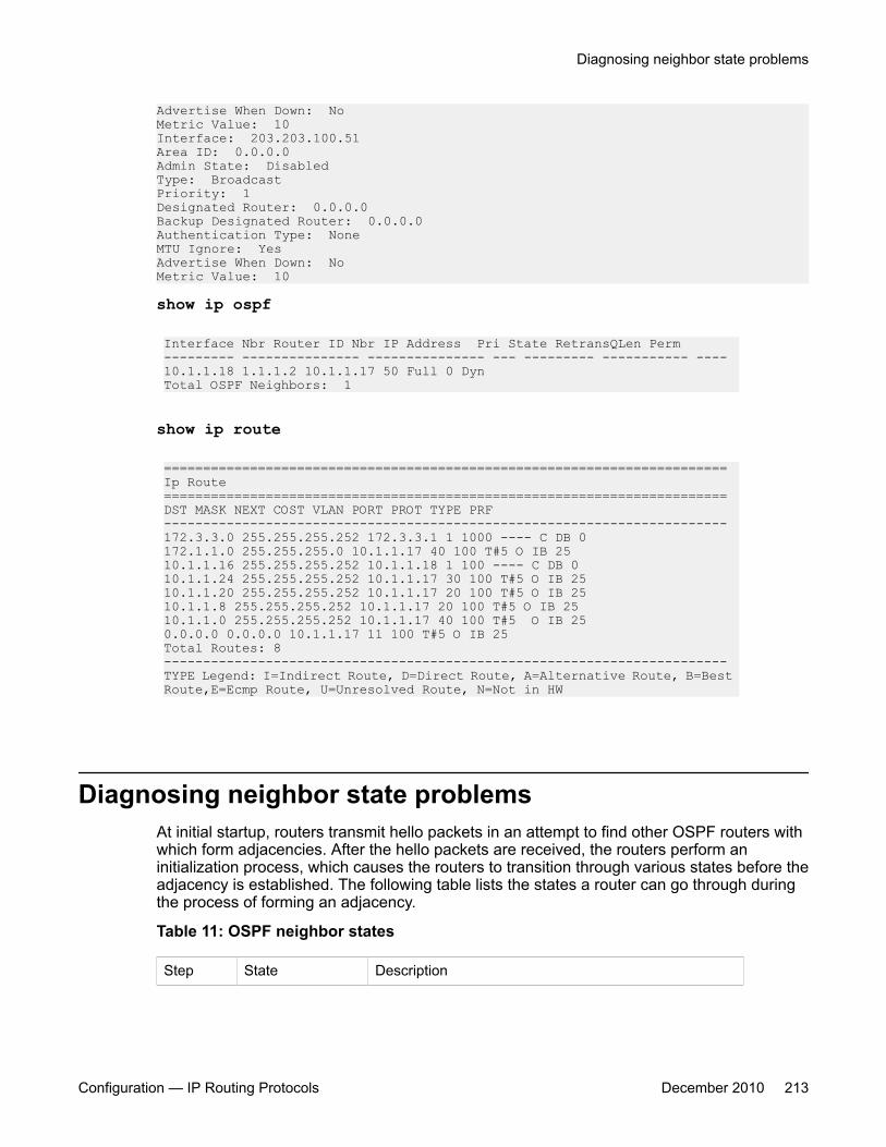
Advertise When Down: NoMetric Value: 10Interface: 203.203.100.51Area ID: 0.0.0.0Admin State: DisabledType: BroadcastPriority: 1Designated Router: 0.0.0.0Backup Designated Router: 0.0.0.0Authentication Type: NoneMTU Ignore: YesAdvertise When Down: NoMetric Value: 10
show ip ospf
Interface Nbr Router ID Nbr IP Address Pri State RetransQLen Perm--------- --------------- --------------- --- --------- ----------- ----10.1.1.18 1.1.1.2 10.1.1.17 50 Full 0 DynTotal OSPF Neighbors: 1
show ip route
========================================================================Ip Route========================================================================DST MASK NEXT COST VLAN PORT PROT TYPE PRF------------------------------------------------------------------------172.3.3.0 255.255.255.252 172.3.3.1 1 1000 ---- C DB 0172.1.1.0 255.255.255.0 10.1.1.17 40 100 T#5 O IB 2510.1.1.16 255.255.255.252 10.1.1.18 1 100 ---- C DB 010.1.1.24 255.255.255.252 10.1.1.17 30 100 T#5 O IB 2510.1.1.20 255.255.255.252 10.1.1.17 20 100 T#5 O IB 2510.1.1.8 255.255.255.252 10.1.1.17 20 100 T#5 O IB 2510.1.1.0 255.255.255.252 10.1.1.17 40 100 T#5 O IB 250.0.0.0 0.0.0.0 10.1.1.17 11 100 T#5 O IB 25Total Routes: 8------------------------------------------------------------------------TYPE Legend: I=Indirect Route, D=Direct Route, A=Alternative Route, B=Best Route,E=Ecmp Route, U=Unresolved Route, N=Not in HW
Diagnosing neighbor state problemsAt initial startup, routers transmit hello packets in an attempt to find other OSPF routers withwhich form adjacencies. After the hello packets are received, the routers perform aninitialization process, which causes the routers to transition through various states before theadjacency is established. The following table lists the states a router can go through duringthe process of forming an adjacency.
Table 11: OSPF neighbor states
Step State Description
Diagnosing neighbor state problems
Configuration — IP Routing Protocols December 2010 213

1 Down Indicates that a neighbor was configured manually, but therouter did not received any information from the otherrouter. This state can occur only on NBMA interfaces.
2 Attempt On an NBMA interface, this state occurs when the routerattempts to send unicast hellos to any configuredinterfaces. The Avaya Ethernet Routing Switch 5000Series does not support NBMA type.
3 Init The router received a general hello packet (without itsRouter ID) from another router.
4 2-Way The router received a Hello directed to it from anotherrouter. (The hello contains its Router ID)
5 ExStart Indicates the start of the Master/Slave election process.
6 Exchange Indicates the link state database (LSDB) is exchanged
7 Loading Indicates the processing state of the LSDB for input intothe routing table. The router can request LSA for missingor corrupt routes.
8 Full Indicates the normal full adjacency state.
OSPF neighbor state informationNeighbor state information can be accessed by using the show ip ospf neighborcommand.
5530-24TFD#show ip ospf neighborInterface Nbr Router ID Nbr IP Address Pri State RetransQLen Perm--------- ------------- -------------- --- ----- ----------- ----10.1.1.22 1.1.1.1 10.1.1.21 100 Full 0 Dyn10.1.1.17 1.1.1.5 10.1.1.18 0 Full 0 Dyn10.1.1.9 1.1.1.4 10.1.1.10 1 Full 0 Dyn
Problems with OSPF occur most often during the initial startup, when the router cannot formadjacencies with other routers and the state is stuck in the Init or ExStart/Exchange state.
Init State ProblemsA router can become stuck in an Init state and not form adjacencies. There are several possiblecauses for this problem:
• Authentication mismatch or configuration problem
• Area mismatch for Stub or NSSA
OSPF configuration examples using ACLI
214 Configuration — IP Routing Protocols December 2010
• Area ID mismatch
• Hello Interval or Dead Interval mismatch
To determine any mismatches in OSPF configuration, use the show ip ospf ifstatsmismatch command.
ExStart/Exchange problemsEven though routers can recognize each other and have moved beyond two waycommunications, routers can become stuck in the ExStart/Exchange state.
A mismatch in maximum transmission unit (MTU) sizes between the routers usually causesthis type of problem. For example, one router could be set for a high MTU size and the otherrouter a smaller value. Depending on the size of the link state database, the router with thesmaller value may not be able to process the larger packets and thus be stuck in this state. Toavoid this problem, ensure that the MTU size value for both routers match. This problem isusually encountered during interoperations in networks with other vendor devices.
Note:The Avaya Ethernet Routing Switch 5000 Series automatically checks for OSPF MTUmismatches.
In the Avaya Ethernet Routing Switch 5000 Series , the supported MTU size for OSPF is 1500bytes by default. Incoming OSPF database description (DBD) packets are dropped if their MTUsize is greater than this value.
Diagnosing neighbor state problems
Configuration — IP Routing Protocols December 2010 215

OSPF configuration examples using ACLI
216 Configuration — IP Routing Protocols December 2010
Chapter 11: RIP configuration using ACLI
This section describes how to configure RIP using ACLI.
RIP is a distance vector protocol used to dynamically discover network routes based on informationpassed between routers in the network.
Prerequisites• Enable IP routing globally.
• Assign an IP address to the VLAN or brouter port that you want to enable with RIP.
Routing is automatically enabled on the VLAN when you assign an IP address to it.
RIP configuration proceduresTo configure RIP routing on the Ethernet Routing Switch, perform the following steps:
Procedure steps
1. Enable RIP globally.2. Configure global RIP properties as required.3. Enable RIP on the desired VLAN or brouter interfaces.4. Configure interface RIP properties as required.
RIP configuration navigation• Configuring the global RIP status on page 218
• Configuring the RIP global timeout, holddown timer, and update timer on page 218
• Configuring the default RIP metric value on page 219
• Displaying global RIP information on page 220
• Configuring the RIP status on an interface on page 221
Configuration — IP Routing Protocols December 2010 217
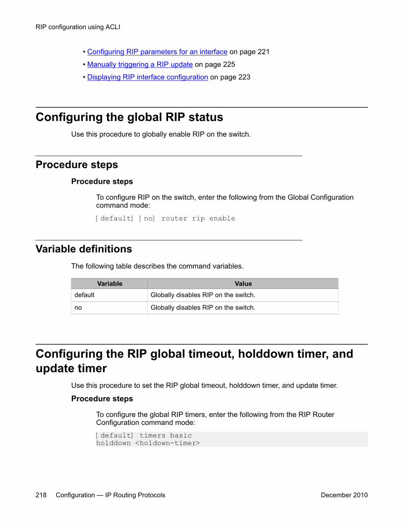
• Configuring RIP parameters for an interface on page 221
• Manually triggering a RIP update on page 225
• Displaying RIP interface configuration on page 223
Configuring the global RIP statusUse this procedure to globally enable RIP on the switch.
Procedure stepsProcedure steps
To configure RIP on the switch, enter the following from the Global Configurationcommand mode:
[default] [no] router rip enable
Variable definitionsThe following table describes the command variables.
Variable Valuedefault Globally disables RIP on the switch.
no Globally disables RIP on the switch.
Configuring the RIP global timeout, holddown timer, andupdate timer
Use this procedure to set the RIP global timeout, holddown timer, and update timer.
Procedure steps
To configure the global RIP timers, enter the following from the RIP RouterConfiguration command mode:
[default] timers basic holddown <holdown-timer>
RIP configuration using ACLI
218 Configuration — IP Routing Protocols December 2010
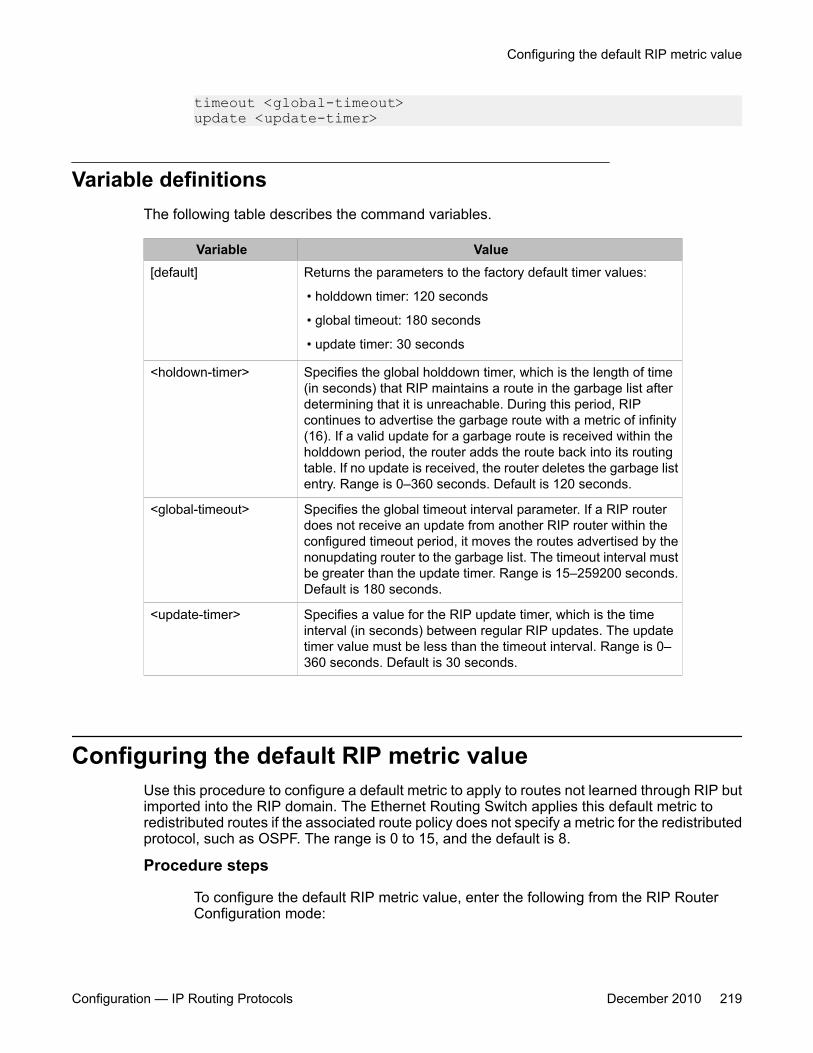
timeout <global-timeout> update <update-timer>
Variable definitionsThe following table describes the command variables.
Variable Value[default] Returns the parameters to the factory default timer values:
• holddown timer: 120 seconds
• global timeout: 180 seconds
• update timer: 30 seconds
<holdown-timer> Specifies the global holddown timer, which is the length of time(in seconds) that RIP maintains a route in the garbage list afterdetermining that it is unreachable. During this period, RIPcontinues to advertise the garbage route with a metric of infinity(16). If a valid update for a garbage route is received within theholddown period, the router adds the route back into its routingtable. If no update is received, the router deletes the garbage listentry. Range is 0–360 seconds. Default is 120 seconds.
<global-timeout> Specifies the global timeout interval parameter. If a RIP routerdoes not receive an update from another RIP router within theconfigured timeout period, it moves the routes advertised by thenonupdating router to the garbage list. The timeout interval mustbe greater than the update timer. Range is 15–259200 seconds.Default is 180 seconds.
<update-timer> Specifies a value for the RIP update timer, which is the timeinterval (in seconds) between regular RIP updates. The updatetimer value must be less than the timeout interval. Range is 0–360 seconds. Default is 30 seconds.
Configuring the default RIP metric valueUse this procedure to configure a default metric to apply to routes not learned through RIP butimported into the RIP domain. The Ethernet Routing Switch applies this default metric toredistributed routes if the associated route policy does not specify a metric for the redistributedprotocol, such as OSPF. The range is 0 to 15, and the default is 8.
Procedure steps
To configure the default RIP metric value, enter the following from the RIP RouterConfiguration mode:
Configuring the default RIP metric value
Configuration — IP Routing Protocols December 2010 219
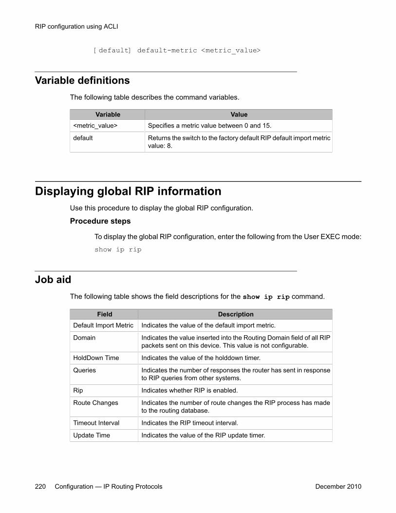
[default] default-metric <metric_value>
Variable definitionsThe following table describes the command variables.
Variable Value<metric_value> Specifies a metric value between 0 and 15.
default Returns the switch to the factory default RIP default import metricvalue: 8.
Displaying global RIP informationUse this procedure to display the global RIP configuration.
Procedure steps
To display the global RIP configuration, enter the following from the User EXEC mode:
show ip rip
Job aidThe following table shows the field descriptions for the show ip rip command.
Field DescriptionDefault Import Metric Indicates the value of the default import metric.
Domain Indicates the value inserted into the Routing Domain field of all RIPpackets sent on this device. This value is not configurable.
HoldDown Time Indicates the value of the holddown timer.
Queries Indicates the number of responses the router has sent in responseto RIP queries from other systems.
Rip Indicates whether RIP is enabled.
Route Changes Indicates the number of route changes the RIP process has madeto the routing database.
Timeout Interval Indicates the RIP timeout interval.
Update Time Indicates the value of the RIP update timer.
RIP configuration using ACLI
220 Configuration — IP Routing Protocols December 2010
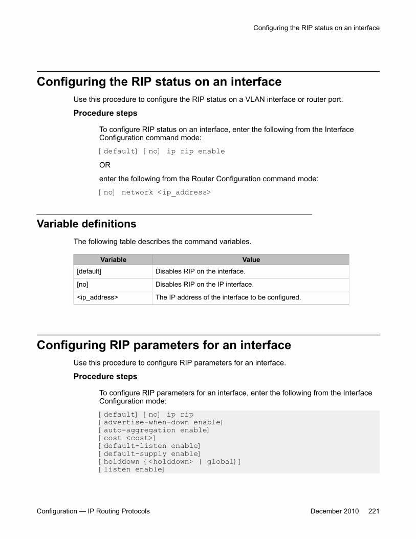
Configuring the RIP status on an interfaceUse this procedure to configure the RIP status on a VLAN interface or router port.
Procedure steps
To configure RIP status on an interface, enter the following from the InterfaceConfiguration command mode:
[default] [no] ip rip enableOR
enter the following from the Router Configuration command mode:
[no] network <ip_address>
Variable definitionsThe following table describes the command variables.
Variable Value[default] Disables RIP on the interface.
[no] Disables RIP on the IP interface.
<ip_address> The IP address of the interface to be configured.
Configuring RIP parameters for an interfaceUse this procedure to configure RIP parameters for an interface.
Procedure steps
To configure RIP parameters for an interface, enter the following from the InterfaceConfiguration mode:
[default] [no] ip rip [advertise-when-down enable] [auto-aggregation enable] [cost <cost>] [default-listen enable] [default-supply enable] [holddown {<holddown> | global}] [listen enable]
Configuring the RIP status on an interface
Configuration — IP Routing Protocols December 2010 221
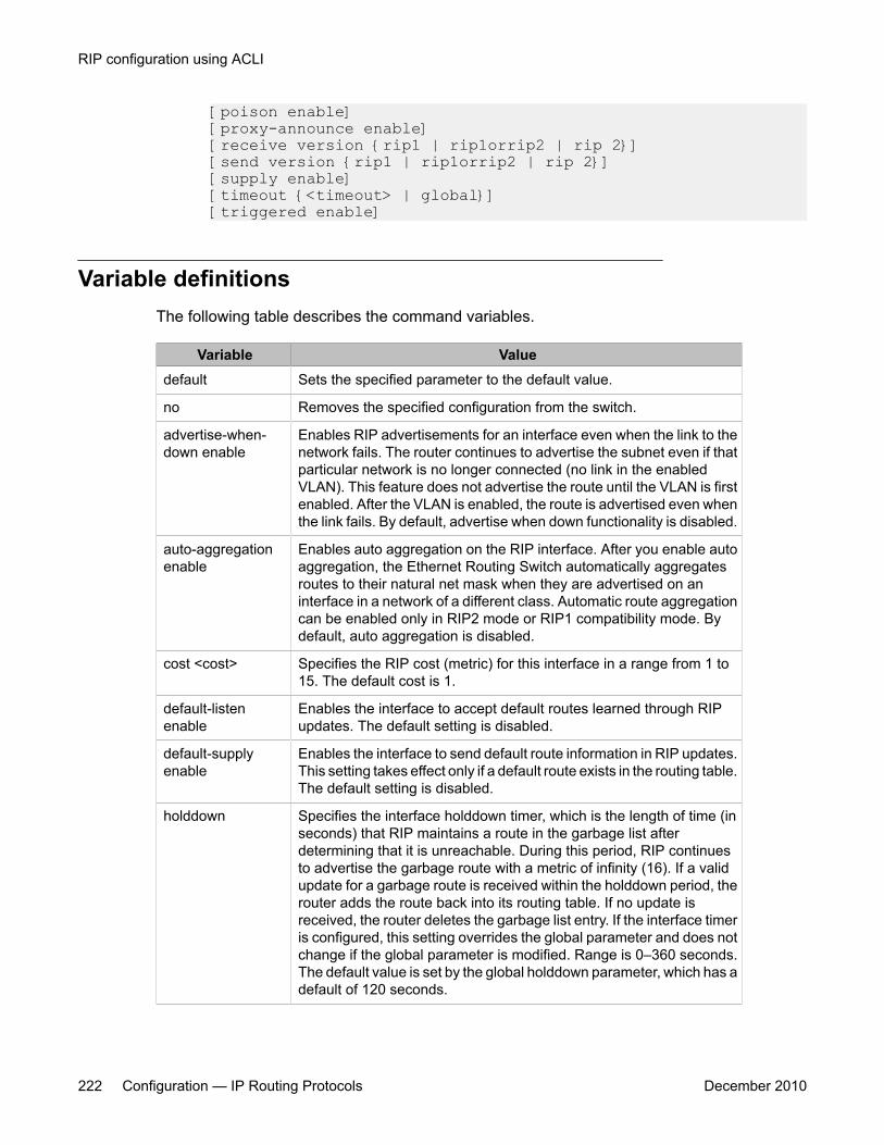
[poison enable] [proxy-announce enable] [receive version {rip1 | rip1orrip2 | rip 2}] [send version {rip1 | rip1orrip2 | rip 2}] [supply enable] [timeout {<timeout> | global}] [triggered enable]
Variable definitionsThe following table describes the command variables.
Variable Valuedefault Sets the specified parameter to the default value.
no Removes the specified configuration from the switch.
advertise-when-down enable
Enables RIP advertisements for an interface even when the link to thenetwork fails. The router continues to advertise the subnet even if thatparticular network is no longer connected (no link in the enabledVLAN). This feature does not advertise the route until the VLAN is firstenabled. After the VLAN is enabled, the route is advertised even whenthe link fails. By default, advertise when down functionality is disabled.
auto-aggregationenable
Enables auto aggregation on the RIP interface. After you enable autoaggregation, the Ethernet Routing Switch automatically aggregatesroutes to their natural net mask when they are advertised on aninterface in a network of a different class. Automatic route aggregationcan be enabled only in RIP2 mode or RIP1 compatibility mode. Bydefault, auto aggregation is disabled.
cost <cost> Specifies the RIP cost (metric) for this interface in a range from 1 to15. The default cost is 1.
default-listenenable
Enables the interface to accept default routes learned through RIPupdates. The default setting is disabled.
default-supplyenable
Enables the interface to send default route information in RIP updates.This setting takes effect only if a default route exists in the routing table.The default setting is disabled.
holddown Specifies the interface holddown timer, which is the length of time (inseconds) that RIP maintains a route in the garbage list afterdetermining that it is unreachable. During this period, RIP continuesto advertise the garbage route with a metric of infinity (16). If a validupdate for a garbage route is received within the holddown period, therouter adds the route back into its routing table. If no update isreceived, the router deletes the garbage list entry. If the interface timeris configured, this setting overrides the global parameter and does notchange if the global parameter is modified. Range is 0–360 seconds.The default value is set by the global holddown parameter, which has adefault of 120 seconds.
RIP configuration using ACLI
222 Configuration — IP Routing Protocols December 2010
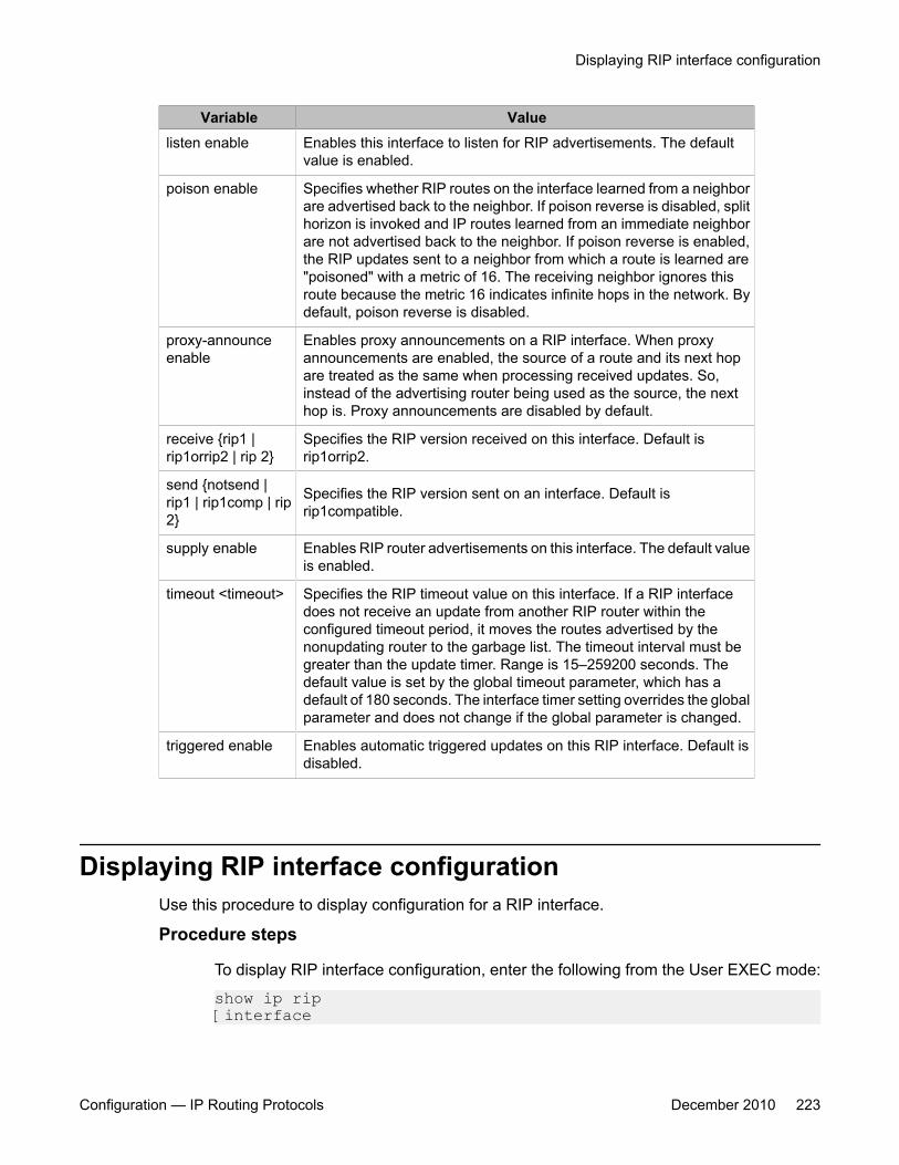
Variable Valuelisten enable Enables this interface to listen for RIP advertisements. The default
value is enabled.
poison enable Specifies whether RIP routes on the interface learned from a neighborare advertised back to the neighbor. If poison reverse is disabled, splithorizon is invoked and IP routes learned from an immediate neighborare not advertised back to the neighbor. If poison reverse is enabled,the RIP updates sent to a neighbor from which a route is learned are"poisoned" with a metric of 16. The receiving neighbor ignores thisroute because the metric 16 indicates infinite hops in the network. Bydefault, poison reverse is disabled.
proxy-announceenable
Enables proxy announcements on a RIP interface. When proxyannouncements are enabled, the source of a route and its next hopare treated as the same when processing received updates. So,instead of the advertising router being used as the source, the nexthop is. Proxy announcements are disabled by default.
receive {rip1 |rip1orrip2 | rip 2}
Specifies the RIP version received on this interface. Default isrip1orrip2.
send {notsend |rip1 | rip1comp | rip2}
Specifies the RIP version sent on an interface. Default isrip1compatible.
supply enable Enables RIP router advertisements on this interface. The default valueis enabled.
timeout <timeout> Specifies the RIP timeout value on this interface. If a RIP interfacedoes not receive an update from another RIP router within theconfigured timeout period, it moves the routes advertised by thenonupdating router to the garbage list. The timeout interval must begreater than the update timer. Range is 15–259200 seconds. Thedefault value is set by the global timeout parameter, which has adefault of 180 seconds. The interface timer setting overrides the globalparameter and does not change if the global parameter is changed.
triggered enable Enables automatic triggered updates on this RIP interface. Default isdisabled.
Displaying RIP interface configurationUse this procedure to display configuration for a RIP interface.
Procedure steps
To display RIP interface configuration, enter the following from the User EXEC mode:
show ip rip [interface
Displaying RIP interface configuration
Configuration — IP Routing Protocols December 2010 223
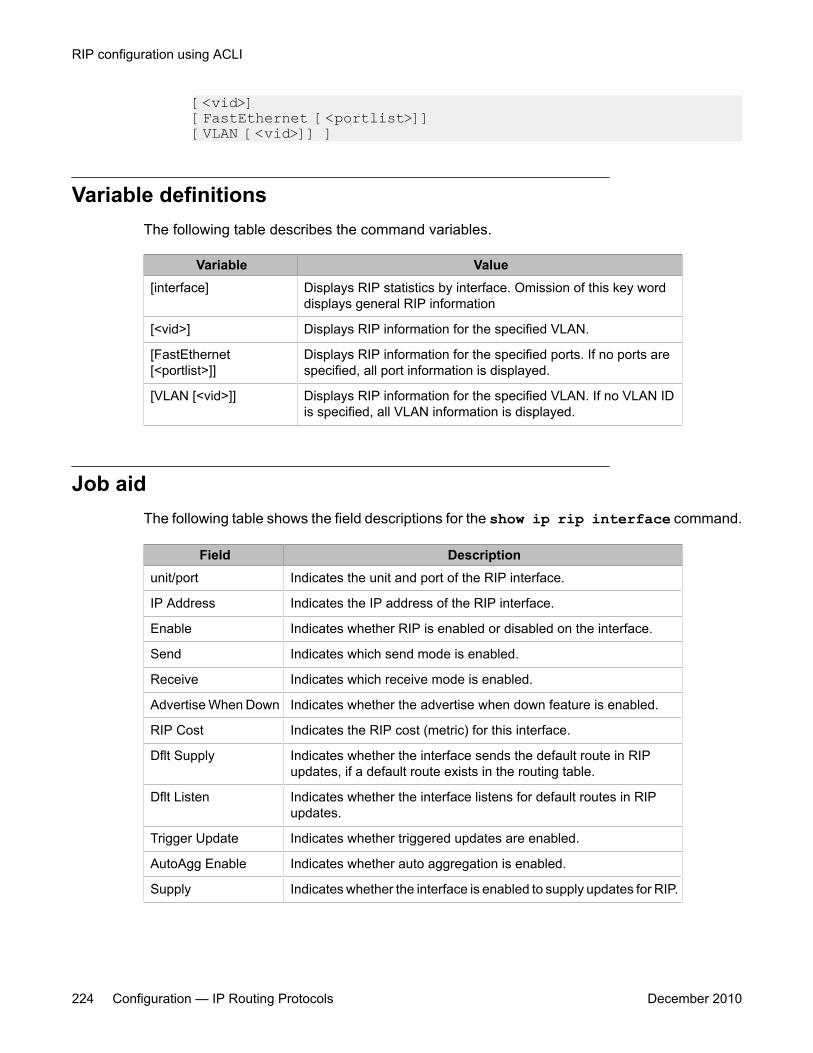
[<vid>] [FastEthernet [<portlist>]] [VLAN [<vid>]] ]
Variable definitionsThe following table describes the command variables.
Variable Value[interface] Displays RIP statistics by interface. Omission of this key word
displays general RIP information
[<vid>] Displays RIP information for the specified VLAN.
[FastEthernet[<portlist>]]
Displays RIP information for the specified ports. If no ports arespecified, all port information is displayed.
[VLAN [<vid>]] Displays RIP information for the specified VLAN. If no VLAN IDis specified, all VLAN information is displayed.
Job aidThe following table shows the field descriptions for the show ip rip interface command.
Field Descriptionunit/port Indicates the unit and port of the RIP interface.
IP Address Indicates the IP address of the RIP interface.
Enable Indicates whether RIP is enabled or disabled on the interface.
Send Indicates which send mode is enabled.
Receive Indicates which receive mode is enabled.
Advertise When Down Indicates whether the advertise when down feature is enabled.
RIP Cost Indicates the RIP cost (metric) for this interface.
Dflt Supply Indicates whether the interface sends the default route in RIPupdates, if a default route exists in the routing table.
Dflt Listen Indicates whether the interface listens for default routes in RIPupdates.
Trigger Update Indicates whether triggered updates are enabled.
AutoAgg Enable Indicates whether auto aggregation is enabled.
Supply Indicates whether the interface is enabled to supply updates for RIP.
RIP configuration using ACLI
224 Configuration — IP Routing Protocols December 2010
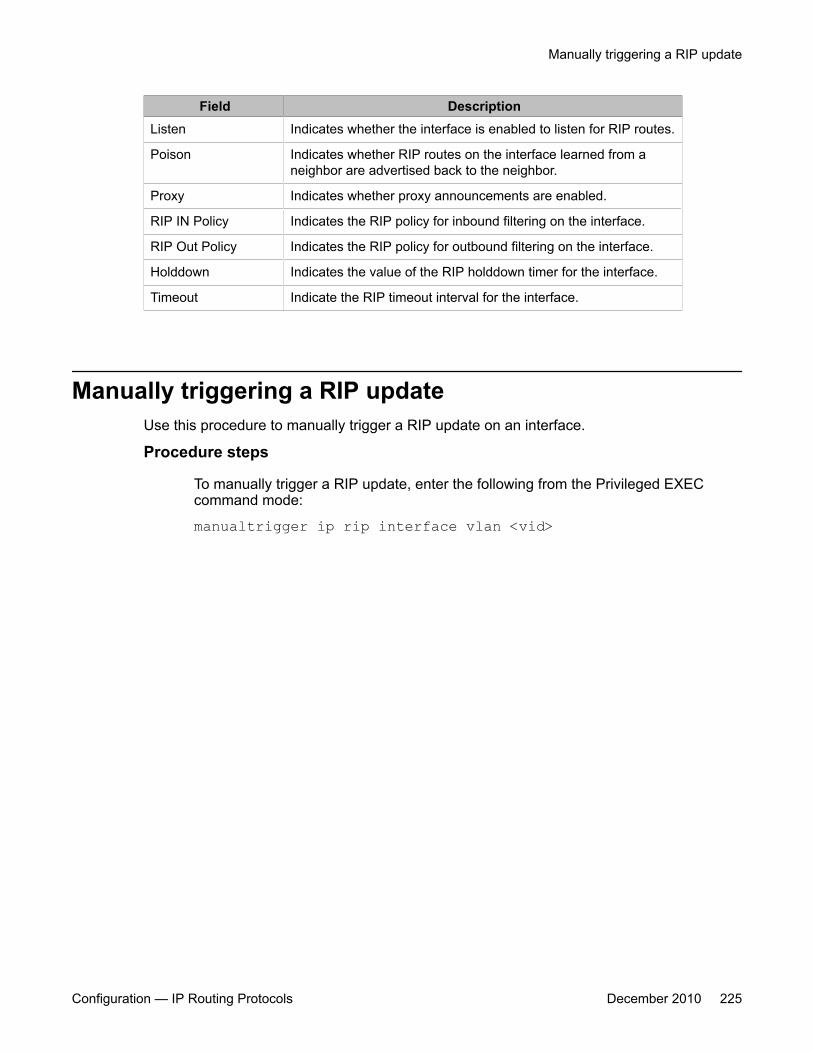
Field DescriptionListen Indicates whether the interface is enabled to listen for RIP routes.
Poison Indicates whether RIP routes on the interface learned from aneighbor are advertised back to the neighbor.
Proxy Indicates whether proxy announcements are enabled.
RIP IN Policy Indicates the RIP policy for inbound filtering on the interface.
RIP Out Policy Indicates the RIP policy for outbound filtering on the interface.
Holddown Indicates the value of the RIP holddown timer for the interface.
Timeout Indicate the RIP timeout interval for the interface.
Manually triggering a RIP updateUse this procedure to manually trigger a RIP update on an interface.
Procedure steps
To manually trigger a RIP update, enter the following from the Privileged EXECcommand mode:
manualtrigger ip rip interface vlan <vid>
Manually triggering a RIP update
Configuration — IP Routing Protocols December 2010 225

RIP configuration using ACLI
226 Configuration — IP Routing Protocols December 2010

Chapter 12: RIP configuration examplesusing ACLI
This section provides configuration examples for common IP routing tasks using ACLI.
This section provides examples of the common RIP configuration tasks and includes the ACLI commandsused to create the configuration.
RIP is configured on a VLAN or brouter port basis.
Note:In many of the following configuration examples, a brouter port is used to create a connection to thenetwork core. This practice does not imply that a brouter port is the only means through which a coreconnection can be established. The use of a brouter port is only one of many ways to create such aconnection.
Navigation• RIP configuration tasks on page 227
• Configuring RIP on page 229
• Configuring RIP version 2 on page 232
• Using RIP accept policies on page 233
• Using RIP announce policies on page 235
RIP configuration tasksTo perform a basic RIP configuration on a VLAN, perform the following steps.
1. Configure the interface, assign an IP address and add ports.5530-24TFD# enable5530-24TFD# config terminal5530-24TFD(config)# vlan create 51 name "VLAN-51" type port5530-24TFD(config)# interface vlan 515530-24TFD(config-if)# ip address 10.10.1.1 255.255.255.0
Configuration — IP Routing Protocols December 2010 227

5530-24TFD(config-if)# exit5530-24TFD(config)# vlan members add 51 8-9
2. Enable RIP using one of the following command sequences.5530-24TFD(config)# interface vlan 515530-24TFD(config-if)# ip rip enable5530-24TFD(config-if)# exit
OR5530-24TFD(config)# router rip5530-24TFD(config-router)# network 10.10.1.15530-24TFD(config-router)# exit
3. Select the VLAN to configure RIP interface properties.
5530-24TFD(config)# interface vlan 514. Disable Supply RIP Updates on the VLAN, if required.
5530-24TFD(config-if)# ip rip supply disable5. Disable Listen for RIP Updates on the VLAN, if required.
5530-24TFD(config-if)# ip rip listen disable6. Enable Default Route Supply on the VLAN, if a default route exists in the route table.
5530-24TFD(config-if)# ip rip default-supply enable7. Enable Default Route Listen on the VLAN to add a default route to the route table, if
advertised from another router.
5530-24TFD(config-if)# ip rip default-listen enable8. Add the Out Route Policy to the VLAN (this step assumes that you have previously
configured the route policy).
5530-24TFD(config-if)# ip rip out-policy map19. Enable Triggered Updates on the VLAN, if required.
5530-24TFD(config-if)# ip rip triggered enable10. Configure the cost of the VLAN link by entering a value of 1 to 15; where 1 is the
default.
5530-24TFD(config-if)# ip rip cost 211. Configure send mode parameters on the VLAN.
5530-24TFD(config-if)# ip rip send version rip212. Configure receive mode parameters on the VLAN.
5530-24TFD(config-if)# ip rip receive version rip213. Enable poison reverse on the VLAN.
5530-24TFD(config-if)# ip rip poison enable
RIP configuration examples using ACLI
228 Configuration — IP Routing Protocols December 2010
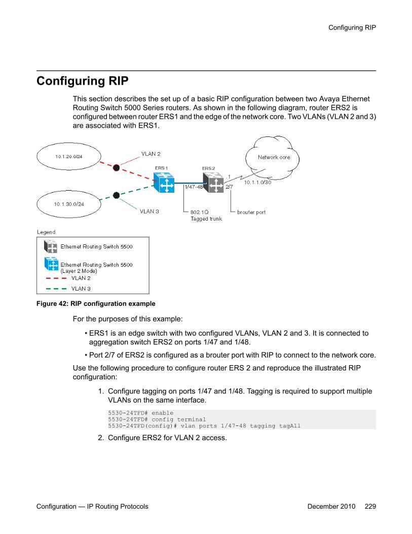
Configuring RIPThis section describes the set up of a basic RIP configuration between two Avaya EthernetRouting Switch 5000 Series routers. As shown in the following diagram, router ERS2 isconfigured between router ERS1 and the edge of the network core. Two VLANs (VLAN 2 and 3)are associated with ERS1.
Figure 42: RIP configuration example
For the purposes of this example:
• ERS1 is an edge switch with two configured VLANs, VLAN 2 and 3. It is connected toaggregation switch ERS2 on ports 1/47 and 1/48.
• Port 2/7 of ERS2 is configured as a brouter port with RIP to connect to the network core.
Use the following procedure to configure router ERS 2 and reproduce the illustrated RIPconfiguration:
1. Configure tagging on ports 1/47 and 1/48. Tagging is required to support multipleVLANs on the same interface.5530-24TFD# enable5530-24TFD# config terminal5530-24TFD(config)# vlan ports 1/47-48 tagging tagAll
2. Configure ERS2 for VLAN 2 access.
Configuring RIP
Configuration — IP Routing Protocols December 2010 229

a. Create a port-based VLAN (VLAN 2) using spanning tree group 1 andinclude ports 1/47 and 1/48 in VLAN 2.5530-24TFD(config)# vlan create 2 name "VLAN-2" typeport5530-24TFD(config)# vlan member add 2 port 1/47-48
b. Assign the IP address 10.1.20.2/24 to VLAN 2.5530-24TFD(config)# interface vlan 25530-24TFD(config-if)# ip address 10.1.20.2255.255.255.0
c. Enable RIP for VLAN 2 and disable RIP supply and listen. RIP supplyand listen are not required because no router is attached to VLAN 2.5530-24TFD(config)# interface vlan 25530-24TFD(config-if)# ip rip enable5530-24TFD(config-if)# ip rip supply disable5530-24TFD(config-if)# ip rip listen disable
3. Configure ERS2 for VLAN 3 access.
a. Create a port-based VLAN (VLAN 3) using spanning tree group 1 andinclude ports 1/47 and 1/48 in VLAN3.5530-24TFD(config)# vlan create 3 name "VLAN-3" typeport5530-24TFD(config)# vlan member add 3 port 1/47-48
b. Assign the IP address 10.1.30.2/24 to VLAN 3.5530-24TFD(config)# interface vlan 35530-24TFD(config-if)# ip address 10.1.30.2 255.255.255.0
c. Enable RIP for VLAN 3 and disable RIP supply and listen. RIP supplyand listen are not required because no router is attached to VLAN 3.5530-24TFD(config)# interface vlan 35530-24TFD(config-if)# ip rip enable5530-24TFD(config-if)# ip rip supply disable5530-24TFD(config-if)# ip rip listen disable
4. Configure brouter port 2/7 on ERS2.
a. Assign the IP address 10.1.1.1/30 to port 2/7 using brouter VLAN 2090.5530-24TFD(config)# interface FastEthernet 2/75530-24TFD(config-if)# brouter vlan 2090 subnet 10.1.1.1/30
Note:Usage of the brouter command above requires the usage ofVariable Length Subnetting. Usage of a dotted decimal subnet maskis not allowed.
RIP configuration examples using ACLI
230 Configuration — IP Routing Protocols December 2010
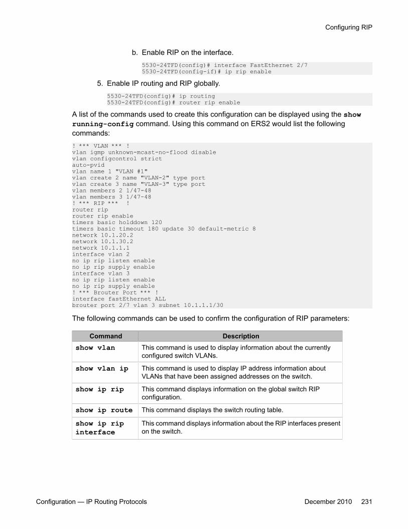
b. Enable RIP on the interface.5530-24TFD(config)# interface FastEthernet 2/75530-24TFD(config-if)# ip rip enable
5. Enable IP routing and RIP globally.5530-24TFD(config)# ip routing5530-24TFD(config)# router rip enable
A list of the commands used to create this configuration can be displayed using the showrunning-config command. Using this command on ERS2 would list the followingcommands:! *** VLAN *** !vlan igmp unknown-mcast-no-flood disablevlan configcontrol strictauto-pvidvlan name 1 "VLAN #1"vlan create 2 name "VLAN-2" type portvlan create 3 name "VLAN-3" type portvlan members 2 1/47-48vlan members 3 1/47-48! *** RIP *** !router riprouter rip enabletimers basic holddown 120timers basic timeout 180 update 30 default-metric 8network 10.1.20.2network 10.1.30.2network 10.1.1.1interface vlan 2no ip rip listen enableno ip rip supply enableinterface vlan 3no ip rip listen enableno ip rip supply enable! *** Brouter Port *** !interface fastEthernet ALLbrouter port 2/7 vlan 3 subnet 10.1.1.1/30
The following commands can be used to confirm the configuration of RIP parameters:
Command Descriptionshow vlan This command is used to display information about the currently
configured switch VLANs.
show vlan ip This command is used to display IP address information aboutVLANs that have been assigned addresses on the switch.
show ip rip This command displays information on the global switch RIPconfiguration.
show ip route This command displays the switch routing table.
show ip ripinterface
This command displays information about the RIP interfaces presenton the switch.
Configuring RIP
Configuration — IP Routing Protocols December 2010 231
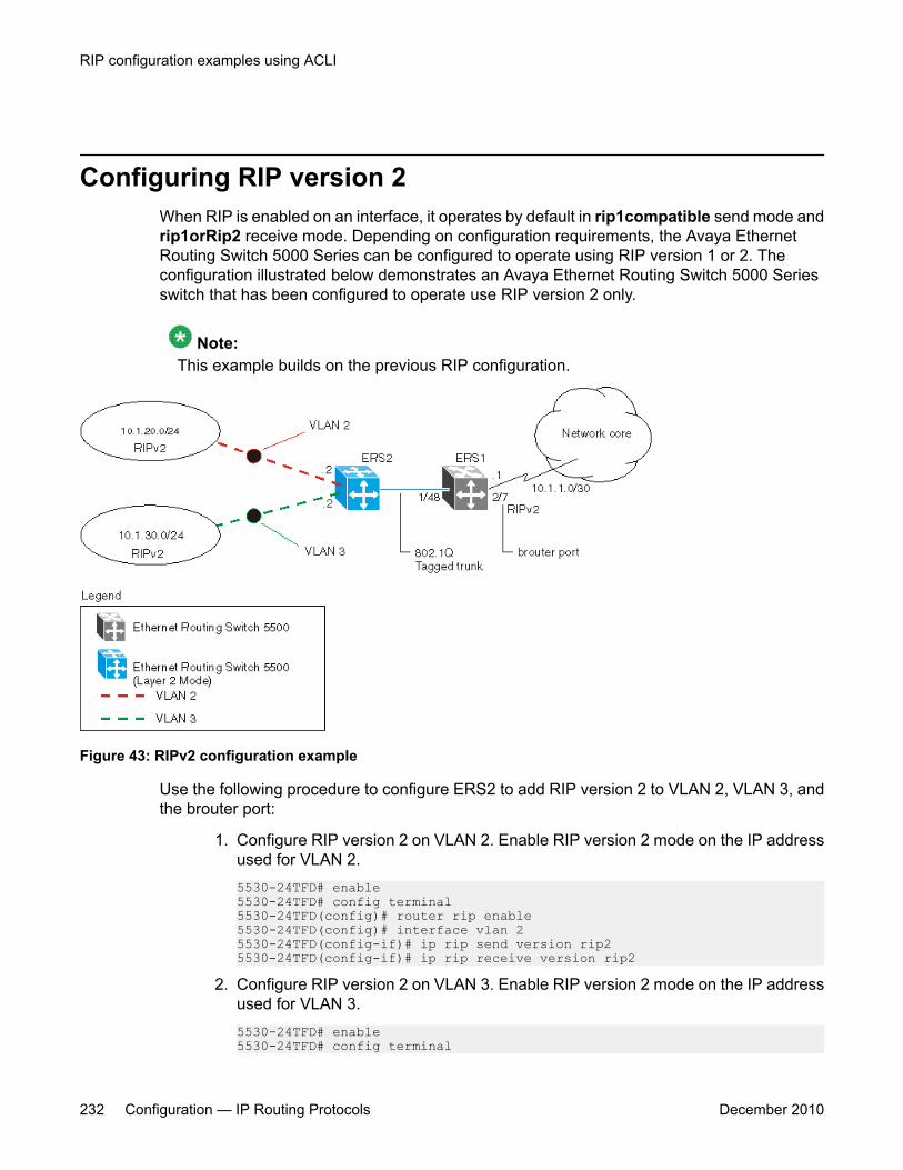
Configuring RIP version 2When RIP is enabled on an interface, it operates by default in rip1compatible send mode andrip1orRip2 receive mode. Depending on configuration requirements, the Avaya EthernetRouting Switch 5000 Series can be configured to operate using RIP version 1 or 2. Theconfiguration illustrated below demonstrates an Avaya Ethernet Routing Switch 5000 Seriesswitch that has been configured to operate use RIP version 2 only.
Note:This example builds on the previous RIP configuration.
Figure 43: RIPv2 configuration example
Use the following procedure to configure ERS2 to add RIP version 2 to VLAN 2, VLAN 3, andthe brouter port:
1. Configure RIP version 2 on VLAN 2. Enable RIP version 2 mode on the IP addressused for VLAN 2.5530-24TFD# enable5530-24TFD# config terminal5530-24TFD(config)# router rip enable5530-24TFD(config)# interface vlan 25530-24TFD(config-if)# ip rip send version rip25530-24TFD(config-if)# ip rip receive version rip2
2. Configure RIP version 2 on VLAN 3. Enable RIP version 2 mode on the IP addressused for VLAN 3.5530-24TFD# enable5530-24TFD# config terminal
RIP configuration examples using ACLI
232 Configuration — IP Routing Protocols December 2010
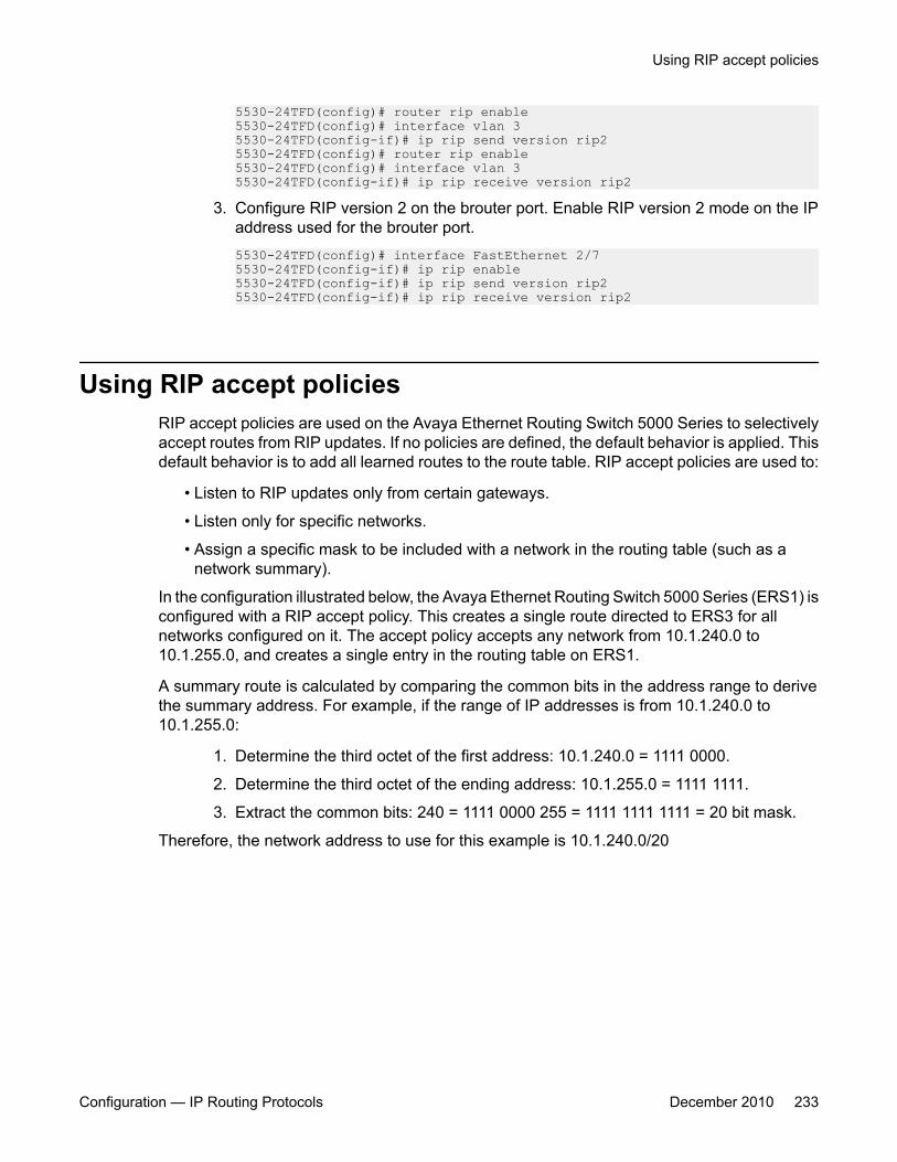
5530-24TFD(config)# router rip enable5530-24TFD(config)# interface vlan 35530-24TFD(config-if)# ip rip send version rip25530-24TFD(config)# router rip enable5530-24TFD(config)# interface vlan 35530-24TFD(config-if)# ip rip receive version rip2
3. Configure RIP version 2 on the brouter port. Enable RIP version 2 mode on the IPaddress used for the brouter port.5530-24TFD(config)# interface FastEthernet 2/75530-24TFD(config-if)# ip rip enable5530-24TFD(config-if)# ip rip send version rip25530-24TFD(config-if)# ip rip receive version rip2
Using RIP accept policiesRIP accept policies are used on the Avaya Ethernet Routing Switch 5000 Series to selectivelyaccept routes from RIP updates. If no policies are defined, the default behavior is applied. Thisdefault behavior is to add all learned routes to the route table. RIP accept policies are used to:
• Listen to RIP updates only from certain gateways.
• Listen only for specific networks.
• Assign a specific mask to be included with a network in the routing table (such as anetwork summary).
In the configuration illustrated below, the Avaya Ethernet Routing Switch 5000 Series (ERS1) isconfigured with a RIP accept policy. This creates a single route directed to ERS3 for allnetworks configured on it. The accept policy accepts any network from 10.1.240.0 to10.1.255.0, and creates a single entry in the routing table on ERS1.
A summary route is calculated by comparing the common bits in the address range to derivethe summary address. For example, if the range of IP addresses is from 10.1.240.0 to10.1.255.0:
1. Determine the third octet of the first address: 10.1.240.0 = 1111 0000.
2. Determine the third octet of the ending address: 10.1.255.0 = 1111 1111.
3. Extract the common bits: 240 = 1111 0000 255 = 1111 1111 1111 = 20 bit mask.
Therefore, the network address to use for this example is 10.1.240.0/20
Using RIP accept policies
Configuration — IP Routing Protocols December 2010 233

Figure 44: Accept policy configuration
Use the following steps to recreate the above configuration example:
1. Configure the IP prefix list on ERS1.
Create a prefix list named Prefix_1 with an IP range from 10.1.240.0 to 10.1.255.0.5530-24TFD(config)# ip prefix-list Prefix_110.1.240.0/20 ge 20 le 32
2. Configure the route policy named rip_pol_1 with match criteria using the IP prefixconfigured in step 1. This injects one route of 10.1.240.0/20 into the route table.5530-24TFD(config)# route-map rip_pol_1 15530-24TFD(config)# route-map rip_pol_1 1 enable5530-24TFD(config)# route-map rip_pol_1 permit 1 enable5530-24TFD(config)# route-map rip_pol_1 permit 1 match network Prefix_15530-24TFD(config)# route-map rip_pol_1 permit 1 set-injectlist Prefix_1
3. Add the route policy created in step 2 to both RIP core ports.5530-24TFD(config)# interface FastEthernet 2/75530-24TFD(config-if)# brouter vlan 2090 subnet 10.1.1.1/305530-24TFD(config-if)# ip rip enable5530-24TFD(config-if)# ip rip in-policy rip_pol_15530-24TFD(config)# interface FastEthernet 2/85530-24TFD(config-if)# brouter vlan 2091 subnet 10.1.1.5/305530-24TFD(config-if)# ip rip enable 5530-24TFD(config-if)# ip rip in-policy rip_pol_1
The show running-config command is used to display the current configuration of aswitch. Using this command on the above configuration would yield the following results:rip_pol_1! *** Route Policies *** !
RIP configuration examples using ACLI
234 Configuration — IP Routing Protocols December 2010
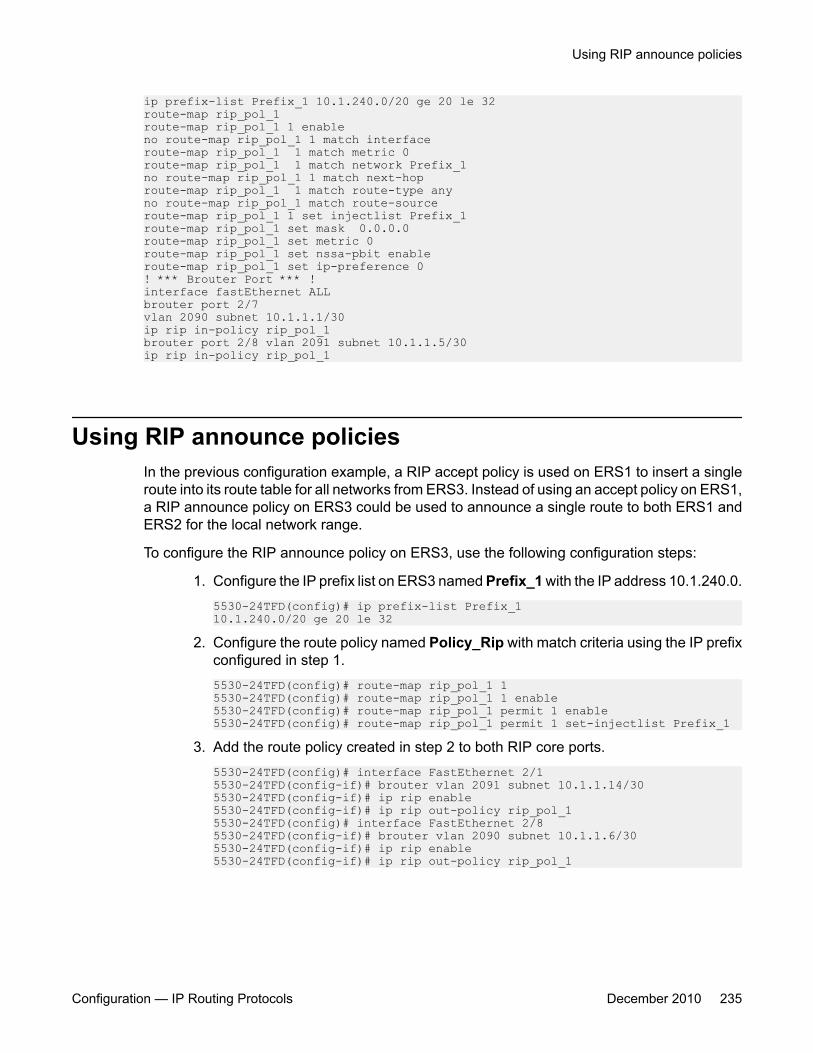
ip prefix-list Prefix_1 10.1.240.0/20 ge 20 le 32route-map rip_pol_1route-map rip_pol_1 1 enableno route-map rip_pol_1 1 match interfaceroute-map rip_pol_1 1 match metric 0route-map rip_pol_1 1 match network Prefix_1no route-map rip_pol_1 1 match next-hoproute-map rip_pol_1 1 match route-type anyno route-map rip_pol_1 match route-sourceroute-map rip_pol_1 1 set injectlist Prefix_1route-map rip_pol_1 set mask 0.0.0.0route-map rip_pol_1 set metric 0route-map rip_pol_1 set nssa-pbit enableroute-map rip_pol_1 set ip-preference 0! *** Brouter Port *** !interface fastEthernet ALLbrouter port 2/7vlan 2090 subnet 10.1.1.1/30ip rip in-policy rip_pol_1brouter port 2/8 vlan 2091 subnet 10.1.1.5/30ip rip in-policy rip_pol_1
Using RIP announce policiesIn the previous configuration example, a RIP accept policy is used on ERS1 to insert a singleroute into its route table for all networks from ERS3. Instead of using an accept policy on ERS1,a RIP announce policy on ERS3 could be used to announce a single route to both ERS1 andERS2 for the local network range.
To configure the RIP announce policy on ERS3, use the following configuration steps:
1. Configure the IP prefix list on ERS3 named Prefix_1 with the IP address 10.1.240.0.5530-24TFD(config)# ip prefix-list Prefix_110.1.240.0/20 ge 20 le 32
2. Configure the route policy named Policy_Rip with match criteria using the IP prefixconfigured in step 1.5530-24TFD(config)# route-map rip_pol_1 15530-24TFD(config)# route-map rip_pol_1 1 enable5530-24TFD(config)# route-map rip_pol_1 permit 1 enable5530-24TFD(config)# route-map rip_pol_1 permit 1 set-injectlist Prefix_1
3. Add the route policy created in step 2 to both RIP core ports.5530-24TFD(config)# interface FastEthernet 2/15530-24TFD(config-if)# brouter vlan 2091 subnet 10.1.1.14/305530-24TFD(config-if)# ip rip enable5530-24TFD(config-if)# ip rip out-policy rip_pol_15530-24TFD(config)# interface FastEthernet 2/85530-24TFD(config-if)# brouter vlan 2090 subnet 10.1.1.6/305530-24TFD(config-if)# ip rip enable5530-24TFD(config-if)# ip rip out-policy rip_pol_1
Using RIP announce policies
Configuration — IP Routing Protocols December 2010 235
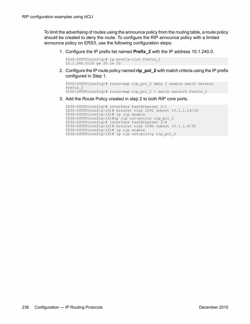
To limit the advertising of routes using the announce policy from the routing table, a route policyshould be created to deny the route. To configure the RIP announce policy with a limitedannounce policy on ERS3, use the following configuration steps:
1. Configure the IP prefix list named Prefix_2 with the IP address 10.1.240.0.5530-24TFD(config)# ip prefix-list Prefix_210.1.240.0/20 ge 20 le 20
2. Configure the IP route policy named rip_pol_2 with match criteria using the IP prefixconfigured in Step 1.5530-24TFD(config)# route-map rip_pol_2 deny 1 enable match network Prefix_25530-24TFD(config)# route-map rip_pol_2 1 match network Prefix_2
3. Add the Route Policy created in step 2 to both RIP core ports.5530-24TFD(config)# interface FastEthernet 2/15530-24TFD(config-if)# brouter vlan 2091 subnet 10.1.1.14/305530-24TFD(config-if)# ip rip enable5530-24TFD(config-if)#ip rip out-policy rip_pol_25530-24TFD(config)# interface FastEthernet 2/85530-24TFD(config-if)# brouter vlan 2090 subnet 10.1.1.6/305530-24TFD(config-if)# ip rip enable5530-24TFD(config-if)# ip rip out-policy rip_pol_2
RIP configuration examples using ACLI
236 Configuration — IP Routing Protocols December 2010
Chapter 13: ECMP configuration using ACLI
This section describes the procedures you can use to configure ECMP using ACLI.
The Equal Cost MultiPath (ECMP) feature allows routers to determine equal cost paths to the samedestination prefix. The multiple paths can be used for load sharing of traffic and allows faster convergenceto other active paths in case of network failure.
Important:ECMP is not supported on the Avaya Ethernet Routing Switch 5510. ECMP works in a mixed stack butcannot run on any Avaya Ethernet Routing Switch 5510 units in the stack.
Prerequisites• Install the Advanced License.
• Enable IP routing globally on the switch.
• Configure routing (RIP, OSPF, or static routes) on the switch.
ECMP configuration navigation• Configuring the number of ECMP paths allotted for RIP on page 237
• Configuring the number of ECMP paths allotted for OSPF on page 238
• Configuring the number of ECMP paths allotted for static routes on page 239
• Displaying ECMP path information on page 239
Configuring the number of ECMP paths allotted for RIPUse this procedure to configure the number of ECMP paths allotted for the Routing InformationProtocol (RIP).
Configuration — IP Routing Protocols December 2010 237

Procedure steps
To configure the number of ECMP paths allotted for RIP, enter the following from theGlobal Configuration mode:
[default] [no] rip maximum-path <path_count>
Variable definitionsThe following table describes the command variables.
Variable Value[default] Sets the maximum ECMP paths allowed to the default value, 1.
[no] Sets the maximum ECMP paths allowed to the default value, 1.
<path_count> Represents the number of ECMP paths allotted. This is a valuebetween 1 and 4. The default is 1.
Configuring the number of ECMP paths allotted for OSPFUse this procedure to configure the number of ECMP paths allotted for the Open Shortest PathFirst (OSPF) protocol.
Procedure steps
To configure the number of ECMP paths allotted for OSPF, enter the following from theGlobal Configuration mode:
[default] [no] ospf maximum-path <path_count>
Variable definitionsThe following table describes the command variables.
Variable Valuedefault Sets the maximum ECMP paths allowed to the default value, 1.
ECMP configuration using ACLI
238 Configuration — IP Routing Protocols December 2010

Variable Value[no] Sets the maximum ECMP paths allowed to the default value, 1.
<path_count> Represents the number of ECMP paths allotted. This is a valuebetween 1 and 4. The default is 1.
Configuring the number of ECMP paths allotted for staticroutes
Use this procedure to configure the number of ECMP paths allotted to static routes.
Procedure steps
To configure the number of ECMP paths allotted to static routes enter the followingfrom the Global Configuration mode:
[default] [no] maximum-path <path_count>
Variable definitionsThe following table describes the command variables.
Variable Valuedefault Sets the maximum ECMP paths allowed to the default value, 1.
no Sets the maximum ECMP paths allowed to the default value, 1.
<path_count> Represents the number of ECMP paths allotted. This is a valuebetween 1 and 4. The default is 1.
Displaying ECMP path informationUse this procedure to display ECMP path information.
Configuring the number of ECMP paths allotted for static routes
Configuration — IP Routing Protocols December 2010 239

Procedure steps
To display ECMP path information, enter the following from the User Exec mode:
show ecmp
Job aidThe following table shows the field descriptions for the show ecmp command.
Field DescriptionProtocol Indicates the protocol.
MAX-PATH Indicates the maximum number of equal-cost paths supported forthe listed protocol.
ECMP configuration examplesEqual Cost Multipath (ECMP) is an IP feature for load-balancing routed IP traffic across up tofour equal-cost paths for each supported protocol. ECMP supports OSPF, RIP, and staticroutes. Some benefits of using ECMP:
• Supported protocols will rerun when an ECMP path fails, and the other configured pathswill automatically take the load.
• Load sharing implies better use of network facilities.ECMP is selected based on the source and destination IP address in the packet. Thehash_control register has a HASH_SELECT field which is set to 5 (lower CRC-32).
R1 = CRC32 (SIP, DIP)
R2 = R1 & 0x1F(The Least Significant 5 bits are selected)
ecmp_index = R2 % (ecmp_count + 1)
Note:The value ecmp_count above is zero-based in the hardware so if four paths are presentthen the value is three. This is why the value is ecmp_count + 1.
The ECMP traffic distribution algorithm is demonstrated in the following example:
Consider two network devices, Device 1 at the IP address 192.1.1.3 and Device 2 at 192.1.1.4.Device 1 send to Device 2 so that 192.1.1.3 is the source IP address (SIP) and 192.1.1.4 isthe destination IP address (Device 2).
ECMP configuration using ACLI
240 Configuration — IP Routing Protocols December 2010
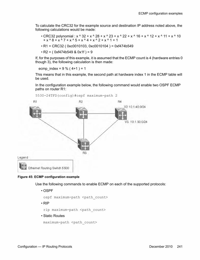
To calculate the CRC32 for the example source and destination IP address noted above, thefollowing calculations would be made:
• CRC32 polynomial : x ^ 32 + x ^ 28 + x ^ 23 + x ^ 22 + x ^ 16 + x ^ 12 + x ^ 11 + x ^ 10+ x ^ 8 + x ^ 7 + x ^ 5 + x ^ 4 + x ^ 2 + x ^ 1 + 1
• R1 = CRC32 ( 0xc0010103, 0xc0010104 ) = 0xf474b549• R2 = ( 0xf474b549 & 0x1f ) = 9
If, for the purposes of this example, it is assumed that the ECMP count is 4 (hardware entries 0though 3), the following calculation is then made:
ecmp_index = 9 % ( 4+1 ) = 1This means that in this example, the second path at hardware index 1 in the ECMP table willbe used.
In the configuration example below, the following command would enable two OSPF ECMPpaths on router R1:
5530-24TFD(config)#ospf maximum-path 2
Figure 45: ECMP configuration example
Use the following commands to enable ECMP on each of the supported protocols:
• OSPF
ospf maximum-path <path_count>• RIP
rip maximum-path <path_count>• Static Routes
maximum-path <path_count>
ECMP configuration examples
Configuration — IP Routing Protocols December 2010 241
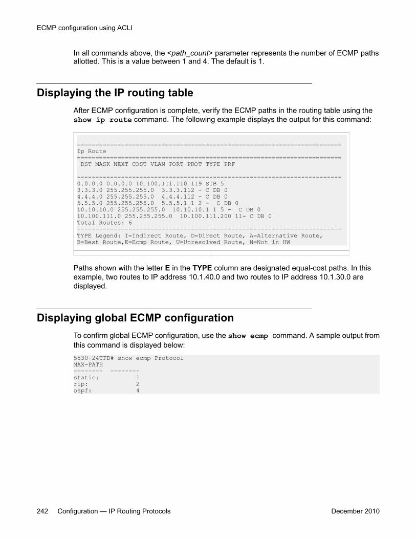
In all commands above, the <path_count> parameter represents the number of ECMP pathsallotted. This is a value between 1 and 4. The default is 1.
Displaying the IP routing tableAfter ECMP configuration is complete, verify the ECMP paths in the routing table using theshow ip route command. The following example displays the output for this command:
======================================================================== Ip Route ======================================================================== DST MASK NEXT COST VLAN PORT PROT TYPE PRF ------------------------------------------------------------------------ 0.0.0.0 0.0.0.0 10.100.111.110 119 SIB 53.3.3.0 255.255.255.0 3.3.3.112 - C DB 04.4.4.0 255.255.255.0 4.4.4.112 - C DB 05.5.5.0 255.255.255.0 5.5.5.1 1 2 - C DB 010.10.10.0 255.255.255.0 10.10.10.1 1 5 - C DB 010.100.111.0 255.255.255.0 10.100.111.200 11- C DB 0 Total Routes: 6 ------------------------------------------------------------------------TYPE Legend: I=Indirect Route, D=Direct Route, A=Alternative Route, B=Best Route,E=Ecmp Route, U=Unresolved Route, N=Not in HW
Paths shown with the letter E in the TYPE column are designated equal-cost paths. In thisexample, two routes to IP address 10.1.40.0 and two routes to IP address 10.1.30.0 aredisplayed.
Displaying global ECMP configurationTo confirm global ECMP configuration, use the show ecmp command. A sample output fromthis command is displayed below:5530-24TFD# show ecmp ProtocolMAX-PATH-------- --------static: 1rip: 2ospf: 4
ECMP configuration using ACLI
242 Configuration — IP Routing Protocols December 2010
Chapter 14: Route policies configurationusing ACLI
This section describes the procedures you can use to configure route policies using ACLI.
Using standard routing schemes, packets are forwarded based on routes that have been learned by therouter through routing protocols such as RIP and OSPF or through the introduction of static routes. Routepolicies provide the ability to forward packets based on rule sets created by the network administrator.These rule sets, or policies, are then applied to the learned or static routes.
Route policies configuration proceduresTo configure routing policies, perform the following steps:
1. Create the appropriate prefix lists.
2. Assign those prefix lists to route maps.
3. Apply the route maps to the appropriate type of policy.
Route policies configuration navigation• Configuring prefix lists on page 244
• Configuring route maps on page 244
• Applying a RIP accept (in) policy on page 247
• Applying a RIP announce (out) policy on page 248
• Configuring an OSPF accept policy on page 249
• Applying the OSPF accept policy on page 250
• Displaying the OSPF accept policy on page 251
• Configuring an OSPF redistribution policy on page 251
• Applying the OSPF redistribution policy on page 252
• Displaying the OSPF redistribution policy on page 253
Configuration — IP Routing Protocols December 2010 243
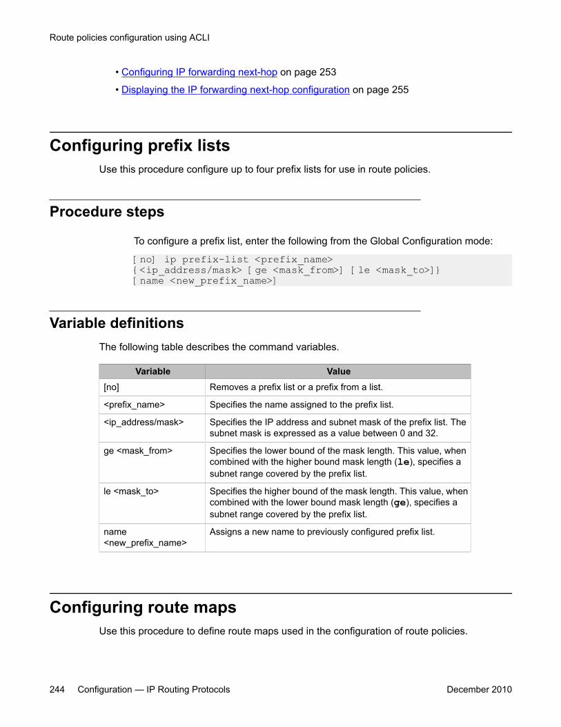
• Configuring IP forwarding next-hop on page 253
• Displaying the IP forwarding next-hop configuration on page 255
Configuring prefix listsUse this procedure configure up to four prefix lists for use in route policies.
Procedure steps
To configure a prefix list, enter the following from the Global Configuration mode:
[no] ip prefix-list <prefix_name> {<ip_address/mask> [ge <mask_from>] [le <mask_to>]} [name <new_prefix_name>]
Variable definitionsThe following table describes the command variables.
Variable Value[no] Removes a prefix list or a prefix from a list.
<prefix_name> Specifies the name assigned to the prefix list.
<ip_address/mask> Specifies the IP address and subnet mask of the prefix list. Thesubnet mask is expressed as a value between 0 and 32.
ge <mask_from> Specifies the lower bound of the mask length. This value, whencombined with the higher bound mask length (le), specifies asubnet range covered by the prefix list.
le <mask_to> Specifies the higher bound of the mask length. This value, whencombined with the lower bound mask length (ge), specifies asubnet range covered by the prefix list.
name<new_prefix_name>
Assigns a new name to previously configured prefix list.
Configuring route mapsUse this procedure to define route maps used in the configuration of route policies.
Route policies configuration using ACLI
244 Configuration — IP Routing Protocols December 2010
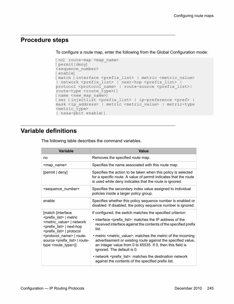
Procedure steps
To configure a route map, enter the following from the Global Configuration mode:
[no] route-map <map_name> [permit|deny] <sequence_number> [enable] [match {interface <prefix_list> | metric <metric_value> | network <prefix_list> | next-hop <prefix_list> | protocol <protocol_name> | route-source <prefix_list>| route-type <route_type>}] [name <new_map_name>] [set {injectlist <prefix_list> | ip-preference <pref> | mask <ip_address> | metric <metric_value> | metric-type <metric_type> | nssa-pbit enable}]
Variable definitionsThe following table describes the command variables.
Variable Valueno Removes the specified route map.
<map_name> Specifies the name associated with this route map.
[permit | deny] Specifies the action to be taken when this policy is selectedfor a specific route. A value of permit indicates that the routeis used while deny indicates that the route is ignored.
<sequence_number> Specifies the secondary index value assigned to individualpolicies inside a larger policy group.
enable Specifies whether this policy sequence number is enabled ordisabled. If disabled, the policy sequence number is ignored.
[match {interface<prefix_list> | metric<metric_value> | network<prefix_list> | next-hop<prefix_list> | protocol<protocol_name> | route-source <prefix_list> | route-type <route_type>}]
If configured, the switch matches the specified criterion:
• interface <prefix_list>: matches the IP address of thereceived interface against the contents of the specified prefixlist.
• metric <metric_value>: matches the metric of the incomingadvertisement or existing route against the specified value,an integer value from 0 to 65535. If 0, then this field isignored. The default is 0.
• network <prefix_list>: matches the destination networkagainst the contents of the specified prefix list.
Configuring route maps
Configuration — IP Routing Protocols December 2010 245

Variable Value
• next-hop <prefix_list>: matches the next hop IP address ofthe route against the contents of the specified prefix list.
• protocol <protocol_name>: matches the protocol throughwhich a route is learned. Options are direct, static, rip, ospf,and any. Multiple protocols can be specified by using acomma-separated list.
• route-source <prefix_list>: matches the source IP addressfor RIP routes against the contents of the specified prefix list.
• route-type <route_type>: Specifies the route type to bematched. Options are any, external, external-1, external-2,internal, and local.
[name <new_map_name>] Specifies a new name to be assigned to a previouslyconfigured route map.
[set {injectlist <prefix_list> |ip-preference <pref> |mask <mask> | metric<metric_value> | metric-type <metric_type> | nssa-pbit enable}]
If configured, the switch sets the specified parameter:
• injectlist <prefix_list>: replaces the destination network ofthe route that matches this policy with the contents of thespecified prefix list.
• ip-preference <pref>: specifies the route preference value tobe assigned to the route that matches this policy. Valid rangeis 0–255. If 0 (the default value), the global preference valueis used. Used for accept policies only.
• mask <mask>: sets the mask of the route that matches thispolicy. Used for RIP accept policies only.
• metric <metric_value>: sets the value of the metric to beassigned to matching routes. This is an integer valuebetween 0 and 65535.
• metric-type <metric_type>: sets the metric type for routes tobe imported into the OSPF routing protocol. Options aretype1 and type2.
• nssa-pbit enable: enables the NSSA N/P-bit, which notifiesthe ABR to export the matching external route. Used forOSPF policies only.
Displaying route mapsUse this procedure to display configured route maps.
Route policies configuration using ACLI
246 Configuration — IP Routing Protocols December 2010

Procedure steps
To display route maps, enter the following from the Global Configuration mode:
show route-map [detail] <map_name>
Variable definitionsThe following table describes the command variables.
Variable Value[detail] Provides detailed information on the route maps.
<map_name> Specifies the name of the route map to display.
Applying a RIP accept (in) policyUse this procedure to specify a RIP Accept (In) policy for an interface. This policy takes theform of a previously configured route map. Only one policy can be created for each RIPinterface.
Procedure steps
1. To specify a RIP Accept policy for an interface, enter the following from the InterfaceConfiguration mode:
[default] [no] ip rip in-policy <rmap_name>2. To display RIP interface configuration, enter the following from the User EXEC
mode:
show ip rip [interface [<vid>] [FastEthernet [<portlist>]] [VLAN [<vid>]] ]
Applying a RIP accept (in) policy
Configuration — IP Routing Protocols December 2010 247
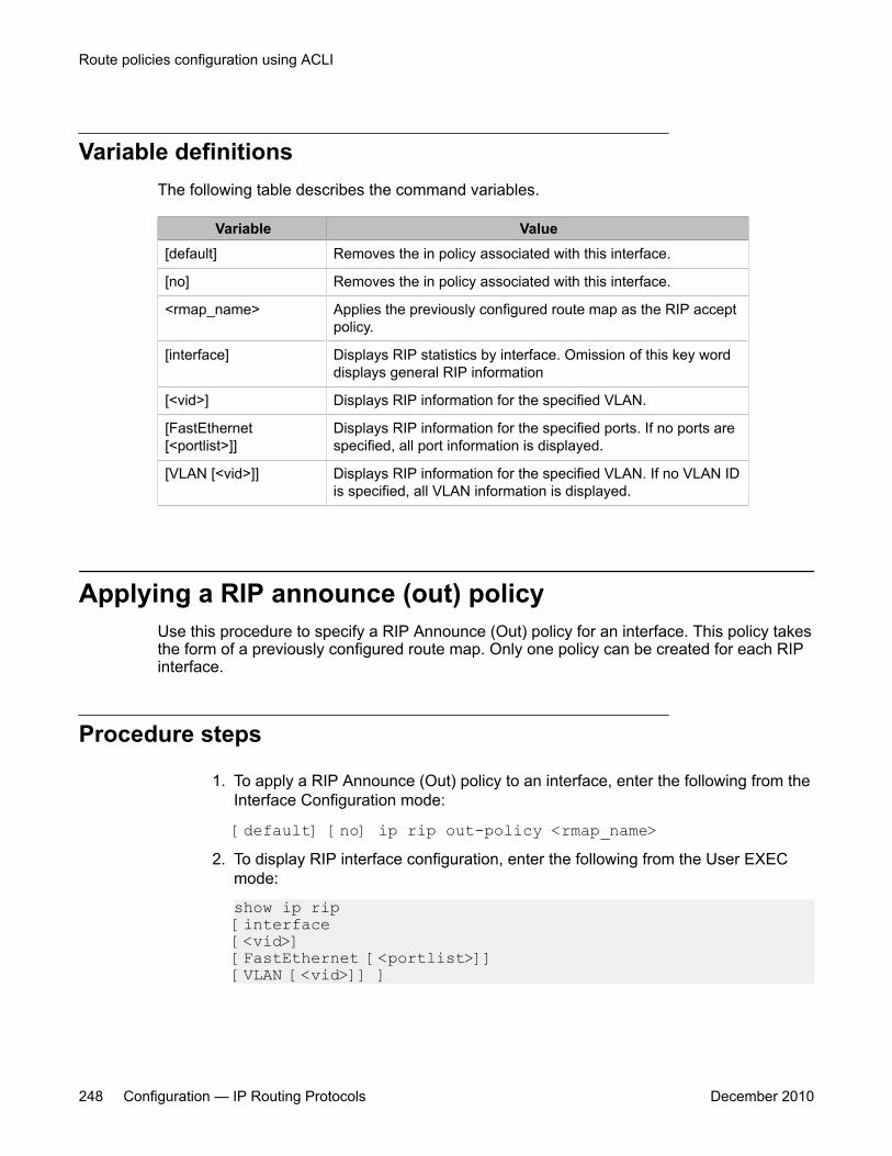
Variable definitionsThe following table describes the command variables.
Variable Value[default] Removes the in policy associated with this interface.
[no] Removes the in policy associated with this interface.
<rmap_name> Applies the previously configured route map as the RIP acceptpolicy.
[interface] Displays RIP statistics by interface. Omission of this key worddisplays general RIP information
[<vid>] Displays RIP information for the specified VLAN.
[FastEthernet[<portlist>]]
Displays RIP information for the specified ports. If no ports arespecified, all port information is displayed.
[VLAN [<vid>]] Displays RIP information for the specified VLAN. If no VLAN IDis specified, all VLAN information is displayed.
Applying a RIP announce (out) policyUse this procedure to specify a RIP Announce (Out) policy for an interface. This policy takesthe form of a previously configured route map. Only one policy can be created for each RIPinterface.
Procedure steps
1. To apply a RIP Announce (Out) policy to an interface, enter the following from theInterface Configuration mode:
[default] [no] ip rip out-policy <rmap_name>2. To display RIP interface configuration, enter the following from the User EXEC
mode:
show ip rip [interface [<vid>] [FastEthernet [<portlist>]] [VLAN [<vid>]] ]
Route policies configuration using ACLI
248 Configuration — IP Routing Protocols December 2010
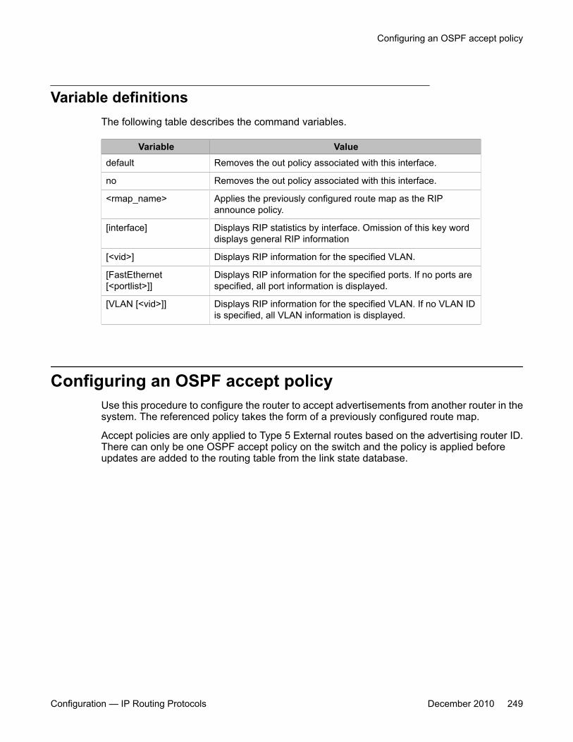
Variable definitionsThe following table describes the command variables.
Variable Valuedefault Removes the out policy associated with this interface.
no Removes the out policy associated with this interface.
<rmap_name> Applies the previously configured route map as the RIPannounce policy.
[interface] Displays RIP statistics by interface. Omission of this key worddisplays general RIP information
[<vid>] Displays RIP information for the specified VLAN.
[FastEthernet[<portlist>]]
Displays RIP information for the specified ports. If no ports arespecified, all port information is displayed.
[VLAN [<vid>]] Displays RIP information for the specified VLAN. If no VLAN IDis specified, all VLAN information is displayed.
Configuring an OSPF accept policyUse this procedure to configure the router to accept advertisements from another router in thesystem. The referenced policy takes the form of a previously configured route map.
Accept policies are only applied to Type 5 External routes based on the advertising router ID.There can only be one OSPF accept policy on the switch and the policy is applied beforeupdates are added to the routing table from the link state database.
Configuring an OSPF accept policy
Configuration — IP Routing Protocols December 2010 249

Procedure steps
To configure the OSPF accept-advertisements router policy, enter the following fromthe OSPF Router Configuration mode:
[no] accept adv-rtr <router_ip_address> [enable] [metric-type {any | type1 | type2}] [route-policy <rmap_name>]
Variable definitionsThe following table describes the command variables.
Variable Value[no] Configures the router to not accept advertisements from another
router in the system.
router_ip_address Represents the IP address of the router from whichadvertisements are to be accepted. The value 0.0.0.0 denotesthat advertisements from all routers are accepted.
enable Enables the accept entry for the router specified in the<ip_address> parameter.
metric-type {any | type1 |type2}
Indicates the type of OSPF external routes that will be acceptedfrom this router.
route-policy<rmap_name>
Specifies the name of a previously configured route map to beused for filtering external routes advertised by the specifiedadvertising router before accepting them into the routing table.
Applying the OSPF accept policyUse this procedure to apply the configured OSPF accept policy to the switch.
Procedure steps
To apply the OSPF accept policy to the switch, enter the following from the GlobalConfiguration mode:
Route policies configuration using ACLI
250 Configuration — IP Routing Protocols December 2010
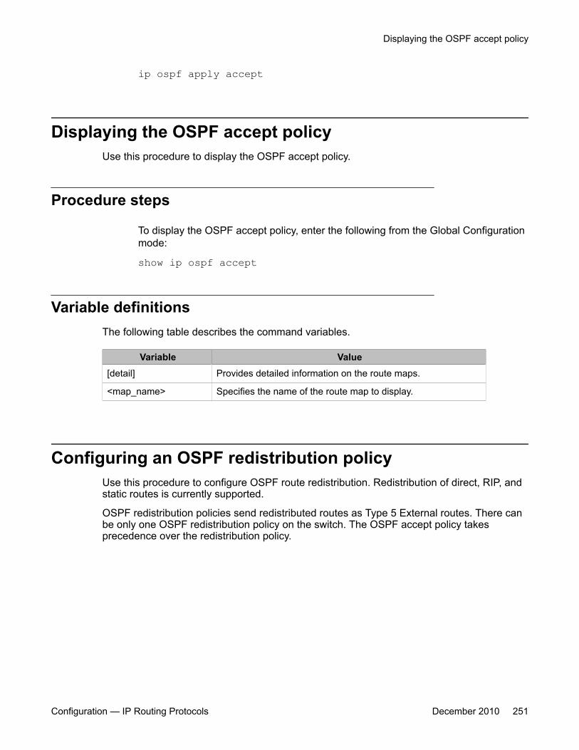
ip ospf apply accept
Displaying the OSPF accept policyUse this procedure to display the OSPF accept policy.
Procedure steps
To display the OSPF accept policy, enter the following from the Global Configurationmode:
show ip ospf accept
Variable definitionsThe following table describes the command variables.
Variable Value[detail] Provides detailed information on the route maps.
<map_name> Specifies the name of the route map to display.
Configuring an OSPF redistribution policyUse this procedure to configure OSPF route redistribution. Redistribution of direct, RIP, andstatic routes is currently supported.
OSPF redistribution policies send redistributed routes as Type 5 External routes. There canbe only one OSPF redistribution policy on the switch. The OSPF accept policy takesprecedence over the redistribution policy.
Displaying the OSPF accept policy
Configuration — IP Routing Protocols December 2010 251

Procedure steps
To configure OSPF route redistribution, enter the following from the RouterConfiguration mode:
redistribute <route_type> [enable] [route-policy <rmap_name>] [metric <metric_value>] [metric-type <metric_type>] [subnets <subnet_setting>
Variable definitionsThe following table describes the command variables.
Variable Value[no] Disables an OSPF route policy or OSPF route redistribution
completely.
<route_type> Specifies the source protocol to be redistributed. Valid optionsare direct, rip, and static.
<rmap_name> Specifies the route policy to associate with route redistribution.This is the name of a previously configured route map.
<metric_value> Specifies the metric value to associate with the routeredistribution. This is an integer value between 0 and 65535.
<metric_type> Specifies the metric type to associate with the routeredistribution. Valid options are type1 and type2.
<subnet_setting> Specifies the subnet advertisement setting of this routeredistribution. This determines whether individual subnets areadvertised. Valid options are allow and suppress.
Applying the OSPF redistribution policyUse this procedure to apply the configured OSPF route redistribution policy to the switch.
Procedure steps
To apply route redistribution to OSPF, enter the following from the Global Configurationmode:
Route policies configuration using ACLI
252 Configuration — IP Routing Protocols December 2010
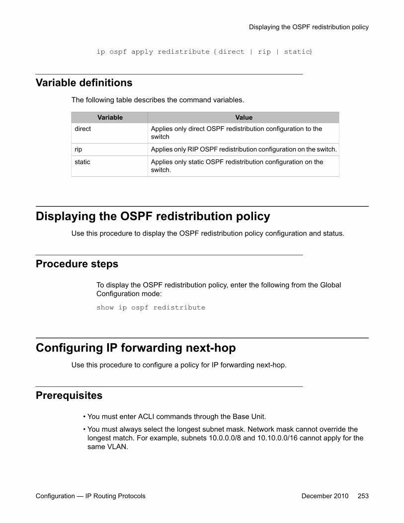
ip ospf apply redistribute {direct | rip | static}
Variable definitionsThe following table describes the command variables.
Variable Valuedirect Applies only direct OSPF redistribution configuration to the
switch
rip Applies only RIP OSPF redistribution configuration on the switch.
static Applies only static OSPF redistribution configuration on theswitch.
Displaying the OSPF redistribution policyUse this procedure to display the OSPF redistribution policy configuration and status.
Procedure steps
To display the OSPF redistribution policy, enter the following from the GlobalConfiguration mode:
show ip ospf redistribute
Configuring IP forwarding next-hopUse this procedure to configure a policy for IP forwarding next-hop.
Prerequisites
• You must enter ACLI commands through the Base Unit.
• You must always select the longest subnet mask. Network mask cannot override thelongest match. For example, subnets 10.0.0.0/8 and 10.10.0.0/16 cannot apply for thesame VLAN.
Displaying the OSPF redistribution policy
Configuration — IP Routing Protocols December 2010 253

• You can create up to a maximum of 4 IP Forwarding Next-hop policies.
• Depending on hardware filter resource availability, up to 16 IP Forwarding Next-hopinstances are allowed. Other applications, such as QoS, can consume hardware filters.
Procedure steps
1. To globally enable the IP forwarding next-hop feature, enter the following fromGlobal Configuration mode:
[no] ip fwd-nh enable2. To create an IP forwarding next-hop policy, enter the following from Global
Configuration mode:
ip fwd-nh <policy-name> match <source-ip/mask> set next-hop <next-hop>
3. To apply an IP forwarding next-hop policy to a VLAN, enter the following fromInterface Configuration mode:
ip fwd-nh policy <policy-name> [mode {drop | normal-routing}]
4. To delete a policy, enter the following from Global Configuration mode:
no ip fwd-nh <policy-name>
Variable definitionsThe following table describes the command variables.
Variable Value<policy-name> Name of the next-hop forwarding policy. The
value consists of any alphanumeric values.
<source-ip/mask> Source IP address and mask length to bematched. IP address 0.0.0.0 is notsupported.
<next-hop> Next hop IP address to be used to forwardthe packet. The next hop must be a directconnection to any of the routing interfaces ofthe switch.
[mode {drop | normal-routing}] Specifies the packet forwarding decision tobe made based when the next-hop is notreachable.
Route policies configuration using ACLI
254 Configuration — IP Routing Protocols December 2010
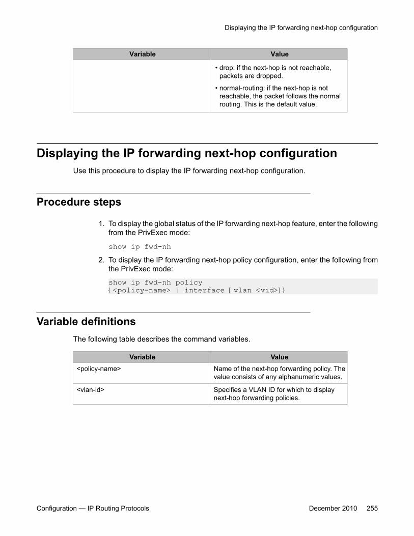
Variable Value
• drop: if the next-hop is not reachable,packets are dropped.
• normal-routing: if the next-hop is notreachable, the packet follows the normalrouting. This is the default value.
Displaying the IP forwarding next-hop configurationUse this procedure to display the IP forwarding next-hop configuration.
Procedure steps
1. To display the global status of the IP forwarding next-hop feature, enter the followingfrom the PrivExec mode:
show ip fwd-nh2. To display the IP forwarding next-hop policy configuration, enter the following from
the PrivExec mode:
show ip fwd-nh policy {<policy-name> | interface [vlan <vid>]}
Variable definitionsThe following table describes the command variables.
Variable Value<policy-name> Name of the next-hop forwarding policy. The
value consists of any alphanumeric values.
<vlan-id> Specifies a VLAN ID for which to displaynext-hop forwarding policies.
Displaying the IP forwarding next-hop configuration
Configuration — IP Routing Protocols December 2010 255

Route policies configuration using ACLI
256 Configuration — IP Routing Protocols December 2010

Chapter 15: DHCP relay configuration usingACLI
This chapter describes the procedures you can use to configure DHCP relay using the ACLI.
Important:DHCP relay uses a hardware resource that is shared by switch Quality of Service applications. WhenDHCP relay is enabled globally, the Quality of Service filter manager will not be able to use precedence11 for configurations. For the filter manager to be able to use this resource, DHCP relay must be disabledfor the entire unit or stack.
Prerequisites• Enable IP routing globally.
• Enable IP routing and configure an IP address on the VLAN to be set as the DHCP relayagent.
• Ensure that a route to the destination DHCP server is available on the switch.
DHCP relay configuration proceduresTo configure DHCP relay, perform the following steps:
1. Ensure that DHCP relay is enabled globally. (DHCP relay is enabled by default.)
2. Configure the DHCP relay forwarding path, specifying the VLAN IP as the DHCPrelay agent and the remote DHCP server as the destination.
3. Enable DHCP for the specific VLAN.
Configuration — IP Routing Protocols December 2010 257

DHCP relay configuration navigation• Configuring global DHCP relay status on page 258
• Displaying the global DHCP relay status on page 259
• Specifying a local DHCP relay agent and remote DHCP server on page 259
• Configuring DHCP relay maximum frame on page 260
• Displaying the DHCP relay configuration on page 260
• Configuring DHCP relay status and parameters on a VLAN on page 261
• Configuring DHCP relay option 82 globally on page 262
• Configuring DHCP relay option 82 on a port on page 262
• Displaying the DHCP relay configuration for a VLAN on page 263
• Displaying DHCP relay counters on page 264
• Clearing DHCP relay counters for a VLAN on page 265
Configuring global DHCP relay statusUse this procedure to configure the global DHCP relay status. DHCP relay is enabled bydefault.
Procedure steps
To configure the global DHCP relay status, enter the following from the GlobalConfiguration mode:
[no] ip dhcp-relay
Variable definitionsThe following table describes the command variables.
Variable Value[no] Disables DHCP relay.
DHCP relay configuration using ACLI
258 Configuration — IP Routing Protocols December 2010
Displaying the global DHCP relay statusUse this procedure to display the current DHCP relay status for the switch.
Procedure steps
To display the global DHCP relay status, enter the following from the User EXECcommand mode:
show ip dhcp-relay
Specifying a local DHCP relay agent and remote DHCPserver
Use this procedure to specify a VLAN as a DHCP relay agent on the forwarding path to aremote DHCP server. The DHCP relay agent can forward DHCP client requests from the localnetwork to the DHCP server in the remote network.
The DHCP relay feature is enabled by default, and the default mode is BootP-DHCP.
Prerequisites
Enable IP routing and configure an IP address on the VLAN to configure as a DHCP relayagent.
Procedure steps
To configure a VLAN as a DHCP relay agent, enter the following from the GlobalConfiguration mode:
Displaying the global DHCP relay status
Configuration — IP Routing Protocols December 2010 259
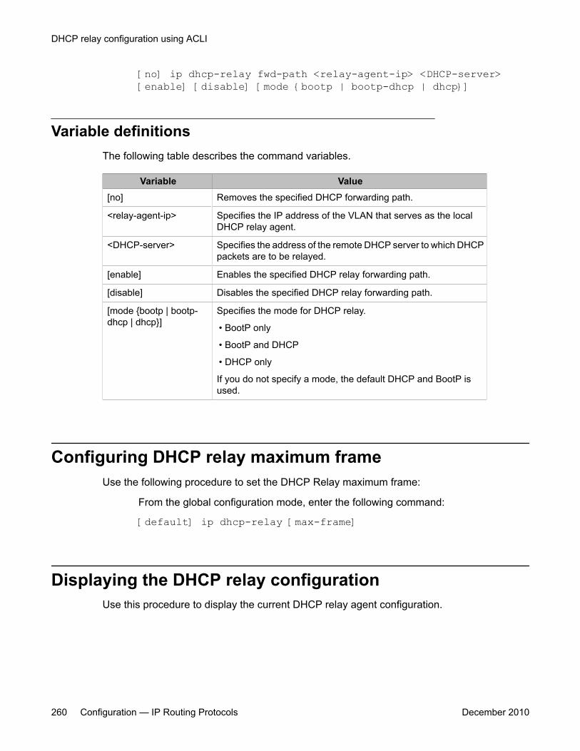
[no] ip dhcp-relay fwd-path <relay-agent-ip> <DHCP-server>[enable] [disable] [mode {bootp | bootp-dhcp | dhcp}]
Variable definitionsThe following table describes the command variables.
Variable Value[no] Removes the specified DHCP forwarding path.
<relay-agent-ip> Specifies the IP address of the VLAN that serves as the localDHCP relay agent.
<DHCP-server> Specifies the address of the remote DHCP server to which DHCPpackets are to be relayed.
[enable] Enables the specified DHCP relay forwarding path.
[disable] Disables the specified DHCP relay forwarding path.
[mode {bootp | bootp-dhcp | dhcp}]
Specifies the mode for DHCP relay.
• BootP only
• BootP and DHCP
• DHCP only
If you do not specify a mode, the default DHCP and BootP isused.
Configuring DHCP relay maximum frameUse the following procedure to set the DHCP Relay maximum frame:
From the global configuration mode, enter the following command:
[default] ip dhcp-relay [max-frame]
Displaying the DHCP relay configurationUse this procedure to display the current DHCP relay agent configuration.
DHCP relay configuration using ACLI
260 Configuration — IP Routing Protocols December 2010
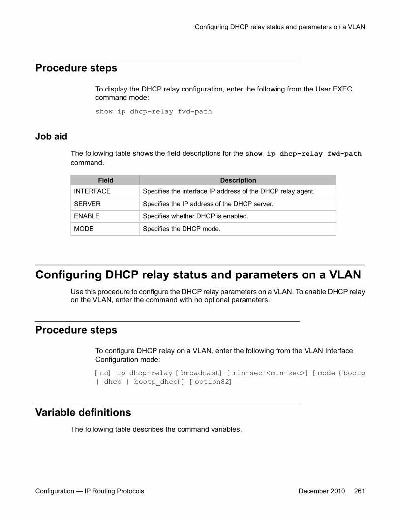
Procedure steps
To display the DHCP relay configuration, enter the following from the User EXECcommand mode:
show ip dhcp-relay fwd-path
Job aid
The following table shows the field descriptions for the show ip dhcp-relay fwd-pathcommand.
Field DescriptionINTERFACE Specifies the interface IP address of the DHCP relay agent.
SERVER Specifies the IP address of the DHCP server.
ENABLE Specifies whether DHCP is enabled.
MODE Specifies the DHCP mode.
Configuring DHCP relay status and parameters on a VLANUse this procedure to configure the DHCP relay parameters on a VLAN. To enable DHCP relayon the VLAN, enter the command with no optional parameters.
Procedure steps
To configure DHCP relay on a VLAN, enter the following from the VLAN InterfaceConfiguration mode:
[no] ip dhcp-relay [broadcast] [min-sec <min-sec>] [mode {bootp| dhcp | bootp_dhcp}] [option82]
Variable definitionsThe following table describes the command variables.
Configuring DHCP relay status and parameters on a VLAN
Configuration — IP Routing Protocols December 2010 261
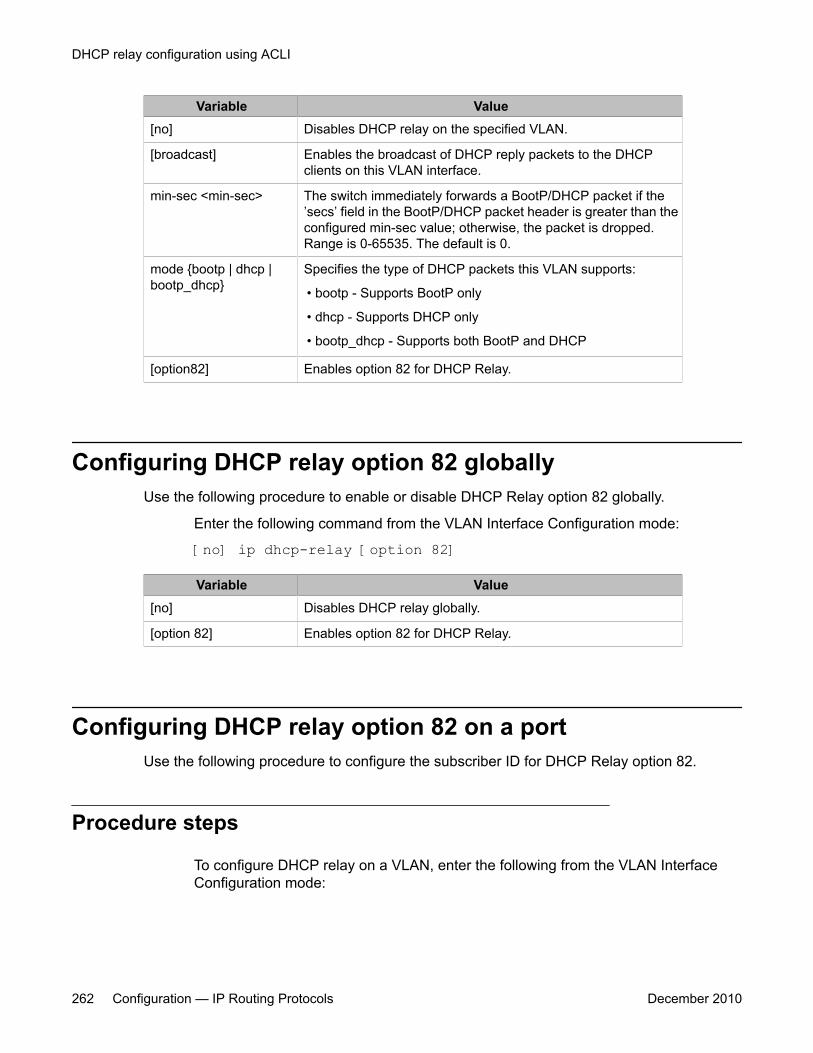
Variable Value[no] Disables DHCP relay on the specified VLAN.
[broadcast] Enables the broadcast of DHCP reply packets to the DHCPclients on this VLAN interface.
min-sec <min-sec> The switch immediately forwards a BootP/DHCP packet if the’secs’ field in the BootP/DHCP packet header is greater than theconfigured min-sec value; otherwise, the packet is dropped.Range is 0-65535. The default is 0.
mode {bootp | dhcp |bootp_dhcp}
Specifies the type of DHCP packets this VLAN supports:
• bootp - Supports BootP only
• dhcp - Supports DHCP only
• bootp_dhcp - Supports both BootP and DHCP
[option82] Enables option 82 for DHCP Relay.
Configuring DHCP relay option 82 globallyUse the following procedure to enable or disable DHCP Relay option 82 globally.
Enter the following command from the VLAN Interface Configuration mode:
[no] ip dhcp-relay [option 82]
Variable Value[no] Disables DHCP relay globally.
[option 82] Enables option 82 for DHCP Relay.
Configuring DHCP relay option 82 on a portUse the following procedure to configure the subscriber ID for DHCP Relay option 82.
Procedure steps
To configure DHCP relay on a VLAN, enter the following from the VLAN InterfaceConfiguration mode:
DHCP relay configuration using ACLI
262 Configuration — IP Routing Protocols December 2010

[no] ip dhcp-relay option82 <subscriber-id>
Variable definitionsThe following table describes the command variables.
Variable Value[no] Removes the specified subscriber ID.
<subscriber-id> Specifies the subscriber ID for DHCP Relay option 82.
Displaying the DHCP relay configuration for a VLANUse this procedure to display the current DHCP relay parameters configured for a VLAN.
Procedure steps
To display the DHCP relay VLAN parameters, enter the following from the PrivilegedEXEC command mode:
show vlan dhcp-relay [<vid>]
Variable definitionsThe following table describes the command variables.
Variable Value[<vid>] Specifies the VLAN ID of the VLAN to be displayed. Range is
1-4094.
Job aidThe following table shows the field descriptions for the show vlan dhcp-relay command.
Field DescriptionIfIndex Indicates the VLAN interface index.
Displaying the DHCP relay configuration for a VLAN
Configuration — IP Routing Protocols December 2010 263

Field DescriptionMIN_SEC Indicates the minimum time, in seconds, to wait between
receiving a DHCP packet and forwarding the DHCP packet to thedestination device. A value of zero indicates forwarding is doneimmediately without delay.
ENABLED Indicates whether DHCP relay is enabled on the VLAN.
MODE Indicates the type of DHCP packets this interface supports.Options include none, BootP, DHCP, and both.
ALWAYS_BROADCAST
Indicates whether DHCP reply packets are broadcast to theDHCP client on this VLAN interface.
OPTION_82 Indicates whether Option 82 is enabled or disabled on the VLAN.
Displaying DHCP relay countersUse this procedure to display the current DHCP relay counters. This includes the number ofrequests and the number of replies.
Procedure steps
To display the DHCP relay counters, enter the following from the User EXEC commandmode:
show ip dhcp-relay counters
Job aidThe following table shows the field descriptions for the show ip dhcp-relay counterscommand.
Field DescriptionINTERFACE Indicates the interface IP address of the DHCP relay agent.
REQUESTS Indicates the number of DHCP requests.
REPLIES Indicates the number of DHCP replies.
DHCP relay configuration using ACLI
264 Configuration — IP Routing Protocols December 2010
Clearing DHCP relay counters for a VLANUse this procedure to clear the DHCP relay counters for a VLAN.
Procedure steps
To clear the DHCP relay counters, enter the following from the VLAN InterfaceConfiguration command mode:
ip dhcp-relay clear-counters
Clearing DHCP relay counters for a VLAN
Configuration — IP Routing Protocols December 2010 265

DHCP relay configuration using ACLI
266 Configuration — IP Routing Protocols December 2010
Chapter 16: UDP broadcast forwardingconfiguration using ACLI
UDP broadcast forwarding is a general mechanism for selectively forwarding limited UDP broadcastsreceived on an IP interface to a configured IP address. This section describes how to configure UDPbroadcast forwarding using ACLI.
The UDP broadcast forwarding feature cannot be enabled or disabled on a global level. When you attachthe first UDP forwarding list to a VLAN interface, the feature is enabled. When you remove the last UDPforwarding list from a VLAN, the feature is disabled.
Prerequisites• Enable IP routing globally.
• Enable IP routing and configure an IP address on the VLAN to be configured as a UDPforwarding interface.
• Ensure that a route to the destination address is available on the switch.
UDP broadcast forwarding configuration proceduresTo configure UDP broadcast forwarding, perform the following steps:
1. Create UDP protocol entries that specify the protocol associated with each UDPport that you want to forward.
2. Create a UDP forwarding list that specifies the destination IP addresses for eachforwarding UDP port. (You can create up to 128 UDP forwarding lists.)
3. Apply UDP forwarding lists to local VLAN interfaces.
Configuration — IP Routing Protocols December 2010 267
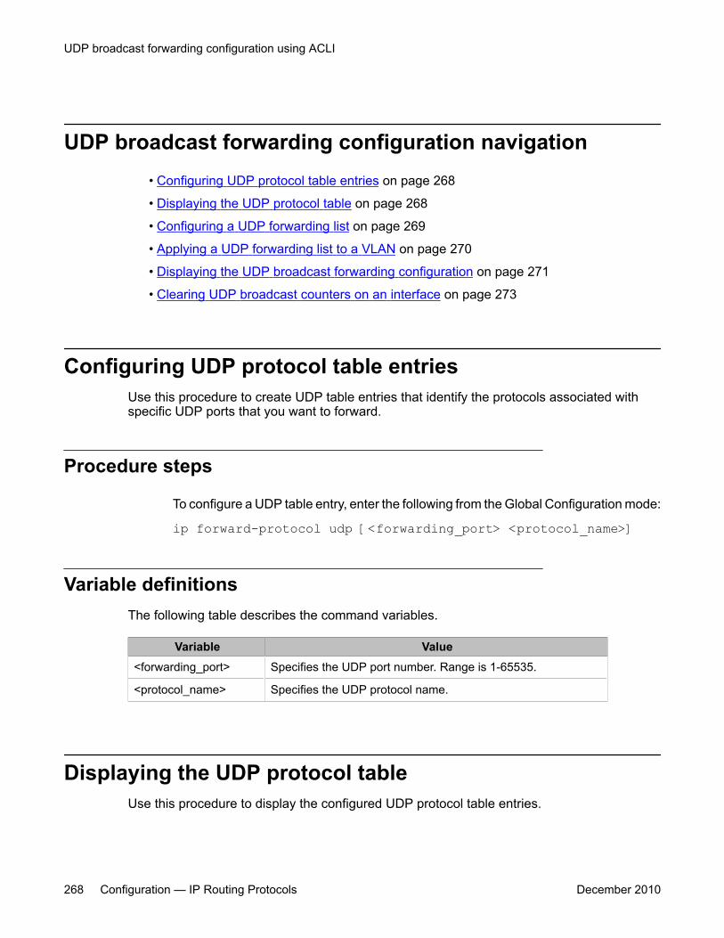
UDP broadcast forwarding configuration navigation• Configuring UDP protocol table entries on page 268
• Displaying the UDP protocol table on page 268
• Configuring a UDP forwarding list on page 269
• Applying a UDP forwarding list to a VLAN on page 270
• Displaying the UDP broadcast forwarding configuration on page 271
• Clearing UDP broadcast counters on an interface on page 273
Configuring UDP protocol table entriesUse this procedure to create UDP table entries that identify the protocols associated withspecific UDP ports that you want to forward.
Procedure steps
To configure a UDP table entry, enter the following from the Global Configuration mode:
ip forward-protocol udp [<forwarding_port> <protocol_name>]
Variable definitionsThe following table describes the command variables.
Variable Value<forwarding_port> Specifies the UDP port number. Range is 1-65535.
<protocol_name> Specifies the UDP protocol name.
Displaying the UDP protocol tableUse this procedure to display the configured UDP protocol table entries.
UDP broadcast forwarding configuration using ACLI
268 Configuration — IP Routing Protocols December 2010
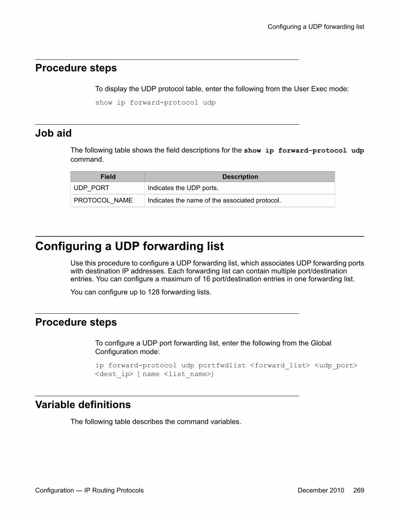
Procedure steps
To display the UDP protocol table, enter the following from the User Exec mode:
show ip forward-protocol udp
Job aidThe following table shows the field descriptions for the show ip forward-protocol udpcommand.
Field DescriptionUDP_PORT Indicates the UDP ports.
PROTOCOL_NAME Indicates the name of the associated protocol.
Configuring a UDP forwarding listUse this procedure to configure a UDP forwarding list, which associates UDP forwarding portswith destination IP addresses. Each forwarding list can contain multiple port/destinationentries. You can configure a maximum of 16 port/destination entries in one forwarding list.
You can configure up to 128 forwarding lists.
Procedure steps
To configure a UDP port forwarding list, enter the following from the GlobalConfiguration mode:
ip forward-protocol udp portfwdlist <forward_list> <udp_port><dest_ip> [name <list_name>]
Variable definitionsThe following table describes the command variables.
Configuring a UDP forwarding list
Configuration — IP Routing Protocols December 2010 269
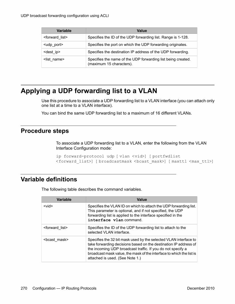
Variable Value<forward_list> Specifies the ID of the UDP forwarding list. Range is 1-128.
<udp_port> Specifies the port on which the UDP forwarding originates.
<dest_ip> Specifies the destination IP address of the UDP forwarding.
<list_name> Specifies the name of the UDP forwarding list being created.(maximum 15 characters).
Applying a UDP forwarding list to a VLANUse this procedure to associate a UDP forwarding list to a VLAN interface (you can attach onlyone list at a time to a VLAN interface).
You can bind the same UDP forwarding list to a maximum of 16 different VLANs.
Procedure steps
To associate a UDP forwarding list to a VLAN, enter the following from the VLANInterface Configuration mode:
ip forward-protocol udp [vlan <vid>] [portfwdlist<forward_list>] [broadcastmask <bcast_mask>] [maxttl <max_ttl>]
Variable definitionsThe following table describes the command variables.
Variable Value<vid> Specifies the VLAN ID on which to attach the UDP forwarding list.
This parameter is optional, and if not specified, the UDPforwarding list is applied to the interface specified in theinterface vlan command.
<forward_list> Specifies the ID of the UDP forwarding list to attach to theselected VLAN interface.
<bcast_mask> Specifies the 32 bit mask used by the selected VLAN interface totake forwarding decisions based on the destination IP address ofthe incoming UDP broadcast traffic. If you do not specify abroadcast mask value, the mask of the interface to which the list isattached is used. (See Note 1.)
UDP broadcast forwarding configuration using ACLI
270 Configuration — IP Routing Protocols December 2010
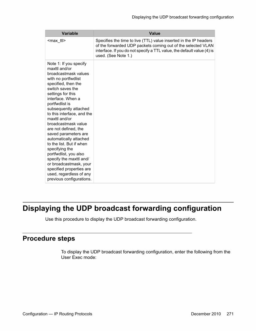
Variable Value<max_ttl> Specifies the time to live (TTL) value inserted in the IP headers
of the forwarded UDP packets coming out of the selected VLANinterface. If you do not specify a TTL value, the default value (4) isused. (See Note 1.)
Note 1: If you specifymaxttl and/orbroadcastmask valueswith no portfwdlistspecified, then theswitch saves thesettings for thisinterface. When aportfwdlist issubsequently attachedto this interface, and themaxttl and/orbroadcastmask valueare not defined, thesaved parameters areautomatically attachedto the list. But if whenspecifying theportfwdlist, you alsospecify the maxttl and/or broadcastmask, yourspecified properties areused, regardless of anyprevious configurations.
Displaying the UDP broadcast forwarding configurationUse this procedure to display the UDP broadcast forwarding configuration.
Procedure steps
To display the UDP broadcast forwarding configuration, enter the following from theUser Exec mode:
Displaying the UDP broadcast forwarding configuration
Configuration — IP Routing Protocols December 2010 271
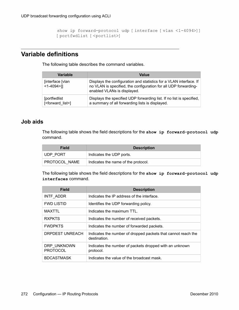
show ip forward-protocol udp [interface [vlan <1-4094>]][portfwdlist [<portlist>]
Variable definitionsThe following table describes the command variables.
Variable Value[interface [vlan<1-4094>]]
Displays the configuration and statistics for a VLAN interface. Ifno VLAN is specified, the configuration for all UDP forwarding-enabled VLANs is displayed.
[portfwdlist[<forward_list>]
Displays the specified UDP forwarding list. If no list is specified,a summary of all forwarding lists is displayed.
Job aids
The following table shows the field descriptions for the show ip forward-protocol udpcommand.
Field DescriptionUDP_PORT Indicates the UDP ports.
PROTOCOL_NAME Indicates the name of the protocol.
The following table shows the field descriptions for the show ip forward-protocol udpinterfaces command.
Field DescriptionINTF_ADDR Indicates the IP address of the interface.
FWD LISTID Identifies the UDP forwarding policy.
MAXTTL Indicates the maximum TTL.
RXPKTS Indicates the number of received packets.
FWDPKTS Indicates the number of forwarded packets.
DRPDEST UNREACH Indicates the number of dropped packets that cannot reach thedestination.
DRP_UNKNOWNPROTOCOL
Indicates the number of packets dropped with an unknownprotocol.
BDCASTMASK Indicates the value of the broadcast mask.
UDP broadcast forwarding configuration using ACLI
272 Configuration — IP Routing Protocols December 2010

The following table shows the field descriptions for the show ip forward-protocol udpportfwdlist command.
Field DescriptionLIST_ID Specifies the specific UDP forwarding policy number.
NAME Specifies the name of the UDP forwarding policy.
Clearing UDP broadcast counters on an interfaceUse this procedure to clear the UDP broadcast counters on an interface.
Procedure steps
To clear the UDP broadcast counters, enter the following from the Privileged ExecConfiguration mode:
clear ip forward-protocol udp counters <1-4094>
Variable definitionsThe following table describes the command variables.
Variable Value<1-4094> Specifies the VLAN ID.
Clearing UDP broadcast counters on an interface
Configuration — IP Routing Protocols December 2010 273

UDP broadcast forwarding configuration using ACLI
274 Configuration — IP Routing Protocols December 2010
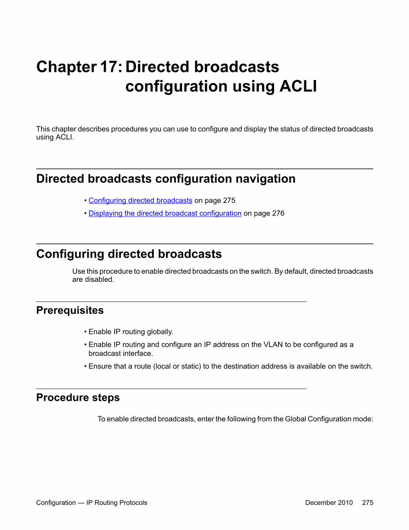
Chapter 17: Directed broadcastsconfiguration using ACLI
This chapter describes procedures you can use to configure and display the status of directed broadcastsusing ACLI.
Directed broadcasts configuration navigation• Configuring directed broadcasts on page 275
• Displaying the directed broadcast configuration on page 276
Configuring directed broadcastsUse this procedure to enable directed broadcasts on the switch. By default, directed broadcastsare disabled.
Prerequisites
• Enable IP routing globally.
• Enable IP routing and configure an IP address on the VLAN to be configured as abroadcast interface.
• Ensure that a route (local or static) to the destination address is available on the switch.
Procedure steps
To enable directed broadcasts, enter the following from the Global Configuration mode:
Configuration — IP Routing Protocols December 2010 275

ip directed-broadcast enable
Displaying the directed broadcast configurationUse this procedure to display the status of directed broadcasts on the switch. By default,directed broadcasts are disabled.
Procedure steps
To display directed broadcast status, enter the following from the User EXEC mode:
show ip directed-broadcast
Directed broadcasts configuration using ACLI
276 Configuration — IP Routing Protocols December 2010
Chapter 18: Static ARP and Proxy ARPconfiguration using ACLI
This chapter describes the procedures you can use to configure Static ARP, Proxy ARP, and display ARPentries using the ACLI.
Static ARP and Proxy ARP configuration navigation• Static ARP configuration on page 277
• Displaying the ARP table on page 278
• Proxy ARP configuration on page 281
Static ARP configurationThis section describes how to configure Static ARP using the ACLI.
Configuring a static ARP entryUse this procedure to create and enable a static ARP entry.
Prerequisites
• Enable IP routing globally.
• Enable IP routing and configure an IP address on the target VLAN.
Procedure steps
To configure a static ARP entry, enter the following from the Global Configuration mode:
Configuration — IP Routing Protocols December 2010 277
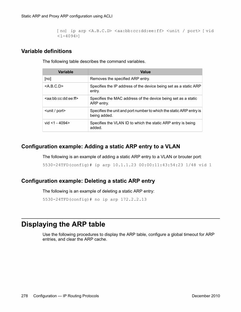
[no] ip arp <A.B.C.D> <aa:bb:cc:dd:ee:ff> <unit / port> [vid<1-4094>]
Variable definitions
The following table describes the command variables.
Variable Value[no] Removes the specified ARP entry.
<A.B.C.D> Specifies the IP address of the device being set as a static ARPentry.
<aa:bb:cc:dd:ee:ff> Specifies the MAC address of the device being set as a staticARP entry.
<unit / port> Specifies the unit and port number to which the static ARP entry isbeing added.
vid <1 - 4094> Specifies the VLAN ID to which the static ARP entry is beingadded.
Configuration example: Adding a static ARP entry to a VLAN
The following is an example of adding a static ARP entry to a VLAN or brouter port:
5530-24TFD(config)# ip arp 10.1.1.23 00:00:11:43:54:23 1/48 vid 1
Configuration example: Deleting a static ARP entry
The following is an example of deleting a static ARP entry:
5530-24TFD(config)# no ip arp 172.2.2.13
Displaying the ARP tableUse the following procedures to display the ARP table, configure a global timeout for ARPentries, and clear the ARP cache.
Static ARP and Proxy ARP configuration using ACLI
278 Configuration — IP Routing Protocols December 2010

Navigation
• Displaying ARP entries on page 279
• Configuring a global timeout for ARP entries on page 280
• Clearing the ARP cache on page 280
Displaying ARP entriesUse this procedure to display ARP entries.
Procedure steps
To display ARP entries, enter the following from the User Exec mode:
show arp-tableOR
show ip arp [static | dynamic] [<ip-addr> | {-s <subnet> <mask>}] [summary]The show ip arp command is invalid if the switch is not in Layer 3 mode.
Variable definitions
The following table describes the command variables.
Variable Value<ip-addr> Specifies the IP address of the ARP entry to be displayed.
-s <subnet> <mask> Displays ARP entries for the specified subnet only.
static Displays all configured static entries, including those without avalid route.
Job aid
The following table shows the field descriptions for the show ip arp command.
Displaying the ARP table
Configuration — IP Routing Protocols December 2010 279
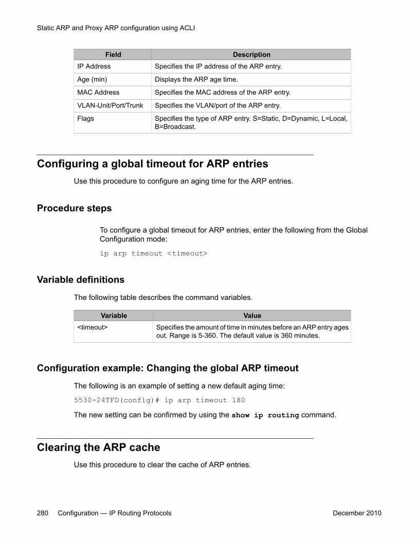
Field DescriptionIP Address Specifies the IP address of the ARP entry.
Age (min) Displays the ARP age time.
MAC Address Specifies the MAC address of the ARP entry.
VLAN-Unit/Port/Trunk Specifies the VLAN/port of the ARP entry.
Flags Specifies the type of ARP entry. S=Static, D=Dynamic, L=Local,B=Broadcast.
Configuring a global timeout for ARP entriesUse this procedure to configure an aging time for the ARP entries.
Procedure steps
To configure a global timeout for ARP entries, enter the following from the GlobalConfiguration mode:
ip arp timeout <timeout>
Variable definitions
The following table describes the command variables.
Variable Value<timeout> Specifies the amount of time in minutes before an ARP entry ages
out. Range is 5-360. The default value is 360 minutes.
Configuration example: Changing the global ARP timeout
The following is an example of setting a new default aging time:
5530-24TFD(config)# ip arp timeout 180The new setting can be confirmed by using the show ip routing command.
Clearing the ARP cacheUse this procedure to clear the cache of ARP entries.
Static ARP and Proxy ARP configuration using ACLI
280 Configuration — IP Routing Protocols December 2010
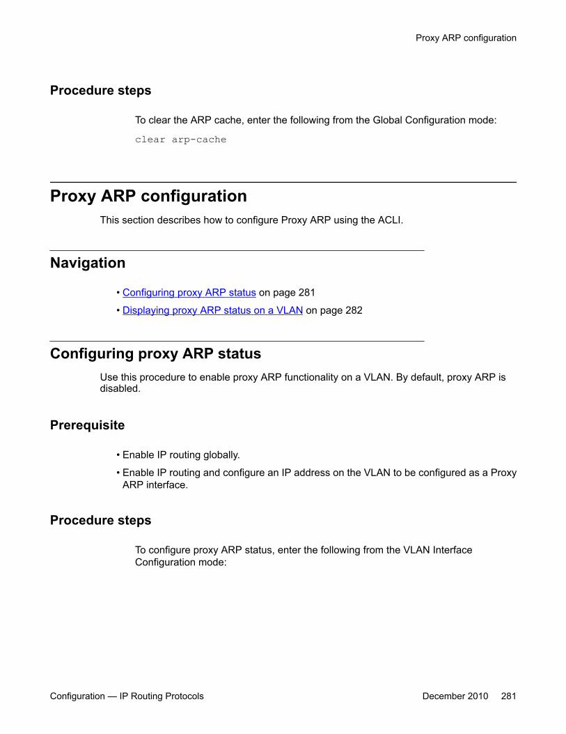
Procedure steps
To clear the ARP cache, enter the following from the Global Configuration mode:
clear arp-cache
Proxy ARP configurationThis section describes how to configure Proxy ARP using the ACLI.
Navigation
• Configuring proxy ARP status on page 281
• Displaying proxy ARP status on a VLAN on page 282
Configuring proxy ARP statusUse this procedure to enable proxy ARP functionality on a VLAN. By default, proxy ARP isdisabled.
Prerequisite
• Enable IP routing globally.
• Enable IP routing and configure an IP address on the VLAN to be configured as a ProxyARP interface.
Procedure steps
To configure proxy ARP status, enter the following from the VLAN InterfaceConfiguration mode:
Proxy ARP configuration
Configuration — IP Routing Protocols December 2010 281
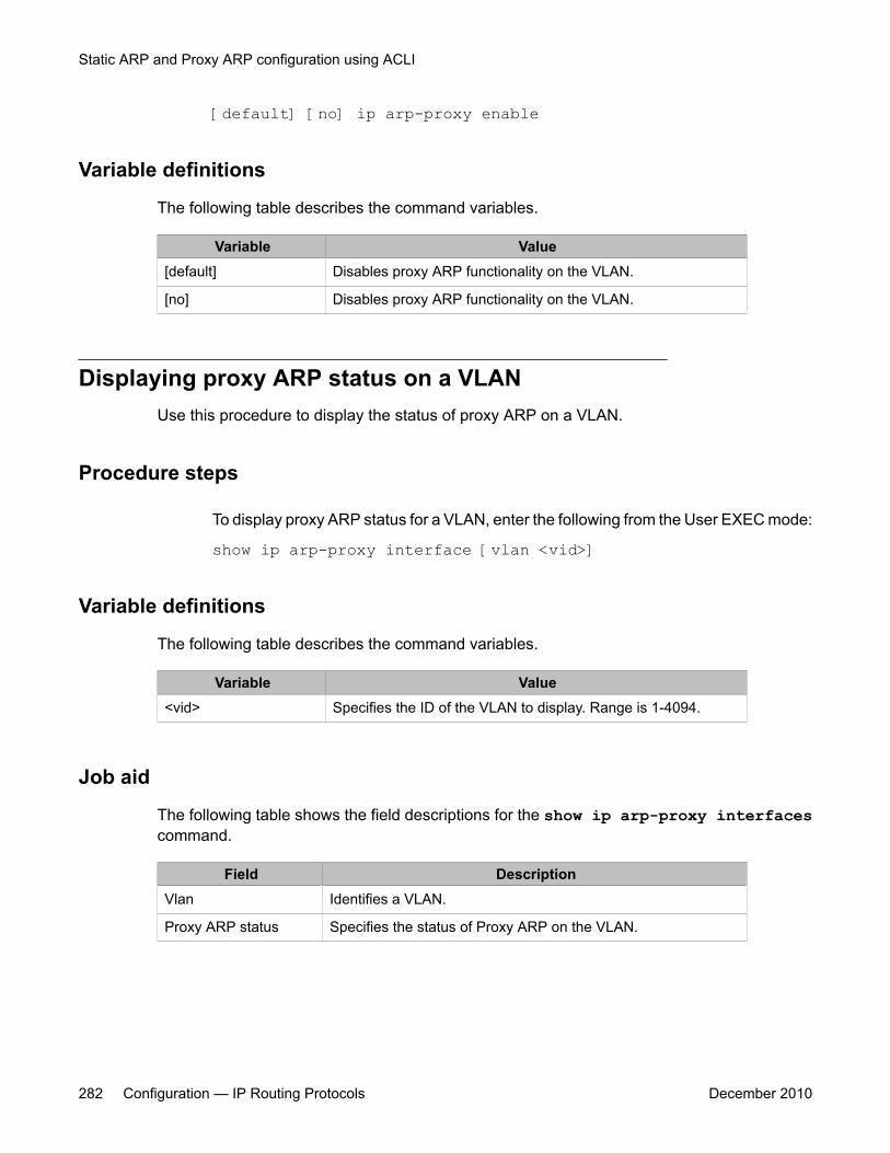
[default] [no] ip arp-proxy enable
Variable definitions
The following table describes the command variables.
Variable Value[default] Disables proxy ARP functionality on the VLAN.
[no] Disables proxy ARP functionality on the VLAN.
Displaying proxy ARP status on a VLANUse this procedure to display the status of proxy ARP on a VLAN.
Procedure steps
To display proxy ARP status for a VLAN, enter the following from the User EXEC mode:
show ip arp-proxy interface [vlan <vid>]
Variable definitions
The following table describes the command variables.
Variable Value<vid> Specifies the ID of the VLAN to display. Range is 1-4094.
Job aid
The following table shows the field descriptions for the show ip arp-proxy interfacescommand.
Field DescriptionVlan Identifies a VLAN.
Proxy ARP status Specifies the status of Proxy ARP on the VLAN.
Static ARP and Proxy ARP configuration using ACLI
282 Configuration — IP Routing Protocols December 2010
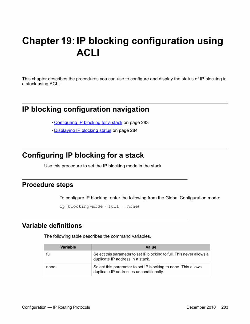
Chapter 19: IP blocking configuration usingACLI
This chapter describes the procedures you can use to configure and display the status of IP blocking ina stack using ACLI.
IP blocking configuration navigation• Configuring IP blocking for a stack on page 283
• Displaying IP blocking status on page 284
Configuring IP blocking for a stackUse this procedure to set the IP blocking mode in the stack.
Procedure steps
To configure IP blocking, enter the following from the Global Configuration mode:
ip blocking-mode {full | none}
Variable definitionsThe following table describes the command variables.
Variable Valuefull Select this parameter to set IP blocking to full. This never allows a
duplicate IP address in a stack.
none Select this parameter to set IP blocking to none. This allowsduplicate IP addresses unconditionally.
Configuration — IP Routing Protocols December 2010 283
Displaying IP blocking statusUse this command to display the status of IP blocking on the switch.
Procedure steps
To display the status of IP blocking on the switch, enter the following from the UserEXEC mode:
show ip blocking
IP blocking configuration using ACLI
284 Configuration — IP Routing Protocols December 2010
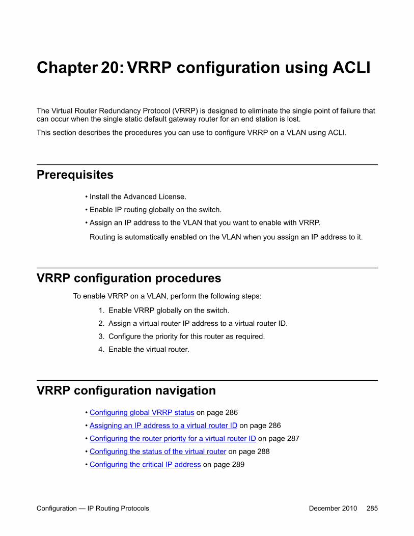
Chapter 20: VRRP configuration using ACLI
The Virtual Router Redundancy Protocol (VRRP) is designed to eliminate the single point of failure thatcan occur when the single static default gateway router for an end station is lost.
This section describes the procedures you can use to configure VRRP on a VLAN using ACLI.
Prerequisites• Install the Advanced License.
• Enable IP routing globally on the switch.
• Assign an IP address to the VLAN that you want to enable with VRRP.
Routing is automatically enabled on the VLAN when you assign an IP address to it.
VRRP configuration proceduresTo enable VRRP on a VLAN, perform the following steps:
1. Enable VRRP globally on the switch.
2. Assign a virtual router IP address to a virtual router ID.
3. Configure the priority for this router as required.
4. Enable the virtual router.
VRRP configuration navigation• Configuring global VRRP status on page 286
• Assigning an IP address to a virtual router ID on page 286
• Configuring the router priority for a virtual router ID on page 287
• Configuring the status of the virtual router on page 288
• Configuring the critical IP address on page 289
Configuration — IP Routing Protocols December 2010 285

• Configuring the VRRP critical IP status on page 289
• Configuring a backup master on page 288
• Configuring the VRRP holddown timer on page 290
• Configuring VRRP holddown action on page 291
• Configuring the VRRP advertisement interval on page 291
• Configuring the fast advertisement interval on page 292
• Configuring fast advertisement status on page 292
• Configuring ICMP echo replies on page 293
• Enabling VRRP traps on page 294
• Displaying VRRP configuration and statistics on page 294
Configuring global VRRP statusUse this procedure to configure the global VRRP status on the switch.
Procedure steps
To configure the global VRRP status on the switch, enter the following from the GlobalConfiguration mode:
[no] router vrrp enable
Variable definitionsThe following table describes the command variables.
Variable Value[no] Globally disables VRRP on the switch.
Assigning an IP address to a virtual router IDUse this procedure to associate an IP address with a virtual router ID.
VRRP configuration using ACLI
286 Configuration — IP Routing Protocols December 2010
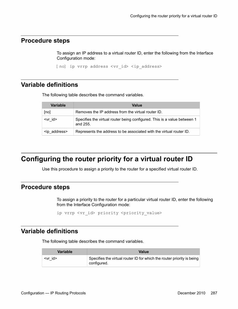
Procedure steps
To assign an IP address to a virtual router ID, enter the following from the InterfaceConfiguration mode:
[no] ip vrrp address <vr_id> <ip_address>
Variable definitionsThe following table describes the command variables.
Variable Value[no] Removes the IP address from the virtual router ID.
<vr_id> Specifies the virtual router being configured. This is a value between 1and 255.
<ip_address> Represents the address to be associated with the virtual router ID.
Configuring the router priority for a virtual router IDUse this procedure to assign a priority to the router for a specified virtual router ID.
Procedure steps
To assign a priority to the router for a particular virtual router ID, enter the followingfrom the Interface Configuration mode:
ip vrrp <vr_id> priority <priority_value>
Variable definitionsThe following table describes the command variables.
Variable Value<vr_id> Specifies the virtual router ID for which the router priority is being
configured.
Configuring the router priority for a virtual router ID
Configuration — IP Routing Protocols December 2010 287
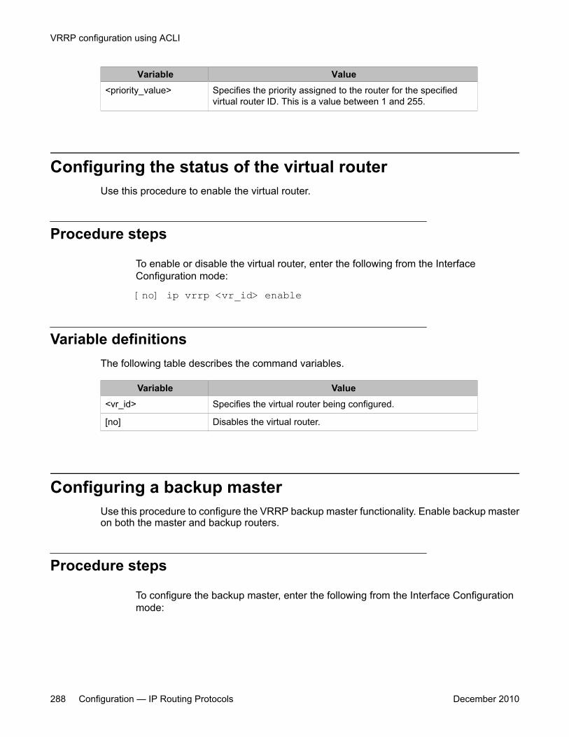
Variable Value<priority_value> Specifies the priority assigned to the router for the specified
virtual router ID. This is a value between 1 and 255.
Configuring the status of the virtual routerUse this procedure to enable the virtual router.
Procedure steps
To enable or disable the virtual router, enter the following from the InterfaceConfiguration mode:
[no] ip vrrp <vr_id> enable
Variable definitionsThe following table describes the command variables.
Variable Value<vr_id> Specifies the virtual router being configured.
[no] Disables the virtual router.
Configuring a backup masterUse this procedure to configure the VRRP backup master functionality. Enable backup masteron both the master and backup routers.
Procedure steps
To configure the backup master, enter the following from the Interface Configurationmode:
VRRP configuration using ACLI
288 Configuration — IP Routing Protocols December 2010

[no] ip vrrp <vr_id> backup-master enable
Variable definitionsThe following table describes the command variables.
Variable Value[no] Disables the VRRP backup master functionality.
<vr_id> Specifies the virtual router being configured.
Configuring the critical IP addressUse this procedure to set the critical IP address on the router.
Procedure steps
To configure the critical IP address, enter the following from the Interface Configurationmode:
[no] ip vrrp <vr_id> critical-ip-addr <ip_address>
Variable definitionsThe following table describes the command variables.
Variable Value<vr_id> Specifies the virtual router being configured.
<ip_address> Specifies the critical IP address to be used.
[no] Removes the configured critical IP.
Configuring the VRRP critical IP statusUse this procedure to configure the status of the VRRP critical IP functionality.
Configuring the critical IP address
Configuration — IP Routing Protocols December 2010 289

Procedure steps
To configure the critical IP status, enter the following from the Interface Configurationmode:
[no] ip vrrp <vr_id> critical-ip enable
Variable definitionsThe following table describes the command variables.
Variable Value<vr_id> Specifies the virtual router being configured.
[no] Disables the VRRP critical IP functionality
Configuring the VRRP holddown timerUse this procedure to set the VRRP holddown timer.
Procedure steps
To set the VRRP holddown timer, enter the following from the Interface Configurationmode:
ip vrrp <vr_id> holddown-timer <timer_value>
Variable definitionsThe following table describes the command variables.
Variable Value<vr_id> Specifies the virtual router being configured.
<timer_value>
Specifies the holddown timer value. This is a value in seconds between 0and 21600.
VRRP configuration using ACLI
290 Configuration — IP Routing Protocols December 2010

Configuring VRRP holddown actionUse this procedure to define the action this interface takes when a holddown timer thresholdhas been reached.
Procedure steps
To define the action for the interface to perform in the holddown state, enter thefollowing from the Interface Configuration mode:
ip vrrp <vr_id> action {none | preempt}
Variable definitionsThe following table describes the command variables.
Variable Value<vr_id> Specifies the virtual router being configured.
{none |preempt}
If none is selected as the action, no action is taken when a holddown timerthreshold is reached. If preempt is selected as the action, the holddowntimer is cancelled.
Configuring the VRRP advertisement intervalUse this procedure to configure the VRRP advertisement interval.
Procedure steps
To configure the VRRP advertisement interval enter the following from the InterfaceConfiguration mode:
Configuring VRRP holddown action
Configuration — IP Routing Protocols December 2010 291

ip vrrp <vr_id> adver-int <interval>
Variable definitionsThe following table describes the command variables.
Variable Value<vr_id> Specifies the virtual router being configured.
<interval> Specifies the advertisement interval in seconds. This is an integer valuebetween 1 and 255
Configuring the fast advertisement intervalUse this procedure to set the interval used in the VRRP fast advertisement functionality.
Procedure steps
To enable or disable fast advertisements, enter the following from the InterfaceConfiguration mode:
ip vrrp <vr_id> fast-adv-int <interval>
Variable definitionsThe following table describes the command variables.
Variable Value<vr_id> Specifies the virtual router being configured.
<interval> Specifies the fast advertisement interval. This is a value in millisecondsbetween 200 and 1000.
Configuring fast advertisement statusUse this procedure to enable the VRRP fast advertisement functionality.
VRRP configuration using ACLI
292 Configuration — IP Routing Protocols December 2010
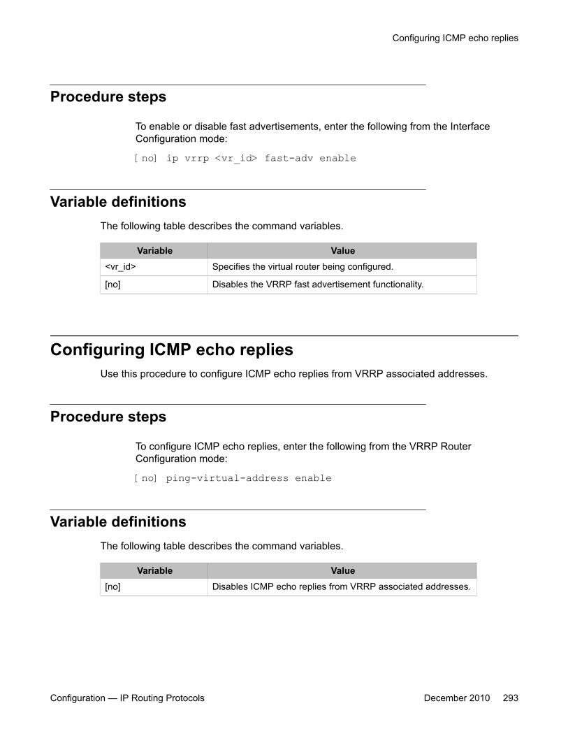
Procedure steps
To enable or disable fast advertisements, enter the following from the InterfaceConfiguration mode:
[no] ip vrrp <vr_id> fast-adv enable
Variable definitionsThe following table describes the command variables.
Variable Value<vr_id> Specifies the virtual router being configured.
[no] Disables the VRRP fast advertisement functionality.
Configuring ICMP echo repliesUse this procedure to configure ICMP echo replies from VRRP associated addresses.
Procedure steps
To configure ICMP echo replies, enter the following from the VRRP RouterConfiguration mode:
[no] ping-virtual-address enable
Variable definitionsThe following table describes the command variables.
Variable Value[no] Disables ICMP echo replies from VRRP associated addresses.
Configuring ICMP echo replies
Configuration — IP Routing Protocols December 2010 293
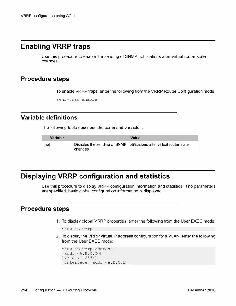
Enabling VRRP trapsUse this procedure to enable the sending of SNMP notifications after virtual router statechanges.
Procedure steps
To enable VRRP traps, enter the following from the VRRP Router Configuration mode:
send-trap enable
Variable definitionsThe following table describes the command variables.
Variable Value[no] Disables the sending of SNMP notifications after virtual router state
changes.
Displaying VRRP configuration and statisticsUse this procedure to display VRRP configuration information and statistics. If no parametersare specified, basic global configuration information is displayed.
Procedure steps
1. To display global VRRP properties, enter the following from the User EXEC mode:
show ip vrrp2. To display the VRRP virtual IP address configuration for a VLAN, enter the following
from the User EXEC mode:
show ip vrrp address [addr <A.B.C.D>] [vrid <1-255>] [interface [addr <A.B.C.D>]
VRRP configuration using ACLI
294 Configuration — IP Routing Protocols December 2010
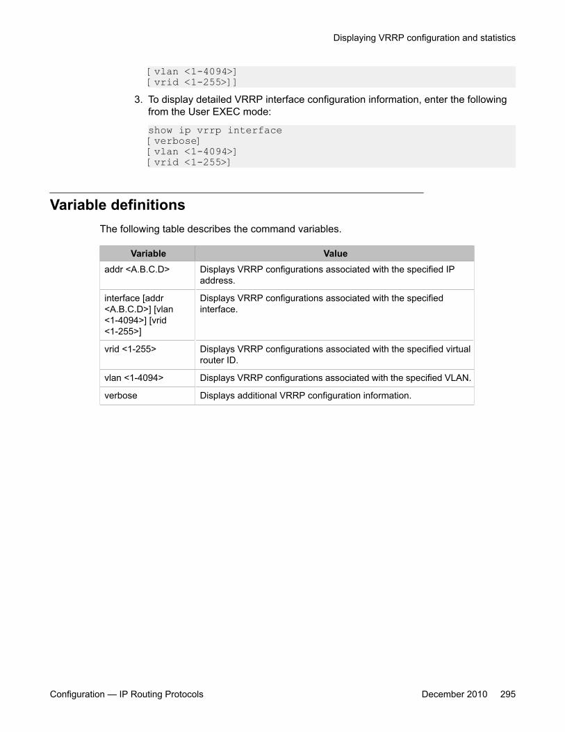
[vlan <1-4094>] [vrid <1-255>]]
3. To display detailed VRRP interface configuration information, enter the followingfrom the User EXEC mode:
show ip vrrp interface [verbose] [vlan <1-4094>] [vrid <1-255>]
Variable definitionsThe following table describes the command variables.
Variable Valueaddr <A.B.C.D> Displays VRRP configurations associated with the specified IP
address.
interface [addr<A.B.C.D>] [vlan<1-4094>] [vrid<1-255>]
Displays VRRP configurations associated with the specifiedinterface.
vrid <1-255> Displays VRRP configurations associated with the specified virtualrouter ID.
vlan <1-4094> Displays VRRP configurations associated with the specified VLAN.
verbose Displays additional VRRP configuration information.
Displaying VRRP configuration and statistics
Configuration — IP Routing Protocols December 2010 295

VRRP configuration using ACLI
296 Configuration — IP Routing Protocols December 2010
Chapter 21: VRRP configuration examplesusing ACLI
This section provides configuration examples showing how to configure VRRP on an Avaya EthernetRouting Switch 5000 Series .
Navigation• Configuring normal VRRP operation on page 297
• Configuring VRRP with SMLT on page 302
• Configuring VRRP with SLT on page 307
Configuring normal VRRP operationThe following configuration example shows how to provide VRRP service for two edge hostlocations.
Configuration — IP Routing Protocols December 2010 297

Figure 46: VRRP example topology
In this example, the switches have the following duties:
• R1 is the VRRP master for S2• R2 is the VRRP master for S1
In this example, VRRP is enabled with OSPF as the routing protocol on R1 and R2.
The VRRP priority setting is used to determine which router will become the VRRP master andwhich will become the VRRP backup. In instances where the priority setting is the same fortwo routers, the higher IP address becomes the tie breaker. Therefore, it is very important toset the correct VRRP priority. VRRP fast advertisement will also be enabled in this example toallow for fast failover detection.
The following procedure describes the steps necessary to reproduce the example describedabove:
1. Configure VLAN 2 on router R1.
a. Create VLAN 2 on router R1.5530-24TFD# config terminal5530-24TFD(config)# vlan create 2 type port
VRRP configuration examples using ACLI
298 Configuration — IP Routing Protocols December 2010
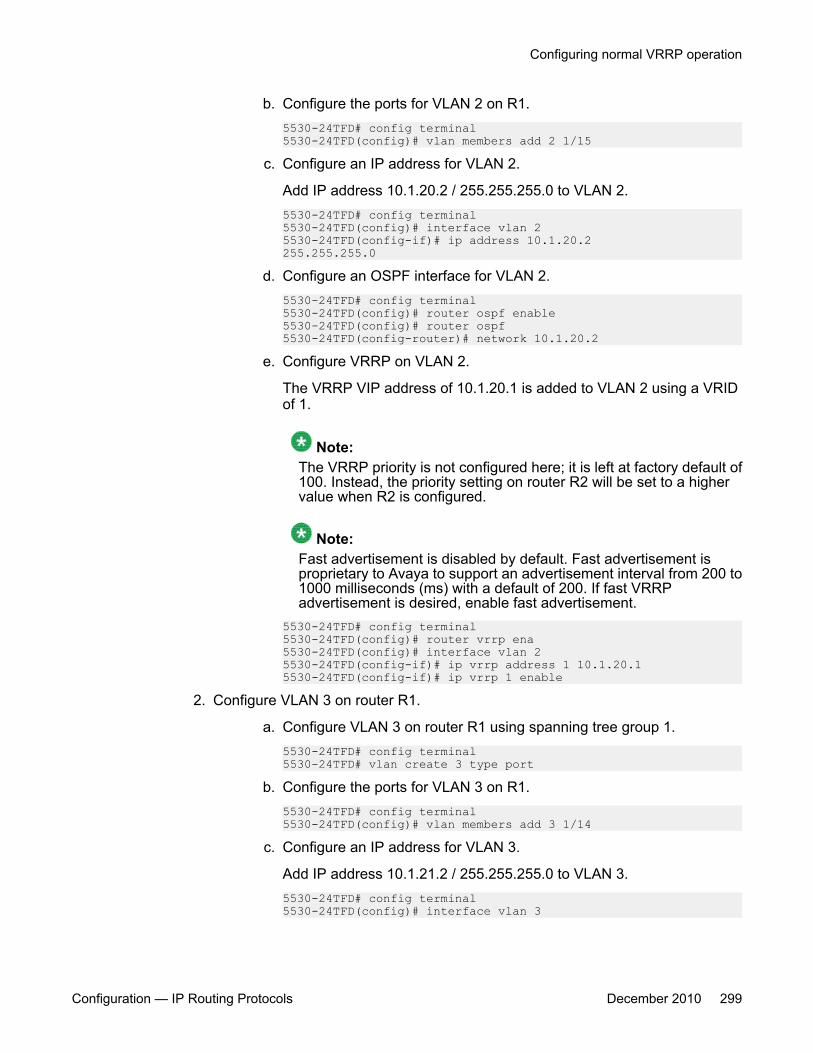
b. Configure the ports for VLAN 2 on R1.5530-24TFD# config terminal5530-24TFD(config)# vlan members add 2 1/15
c. Configure an IP address for VLAN 2.
Add IP address 10.1.20.2 / 255.255.255.0 to VLAN 2.5530-24TFD# config terminal5530-24TFD(config)# interface vlan 25530-24TFD(config-if)# ip address 10.1.20.2255.255.255.0
d. Configure an OSPF interface for VLAN 2.5530-24TFD# config terminal5530-24TFD(config)# router ospf enable5530-24TFD(config)# router ospf5530-24TFD(config-router)# network 10.1.20.2
e. Configure VRRP on VLAN 2.
The VRRP VIP address of 10.1.20.1 is added to VLAN 2 using a VRIDof 1.
Note:The VRRP priority is not configured here; it is left at factory default of100. Instead, the priority setting on router R2 will be set to a highervalue when R2 is configured.
Note:Fast advertisement is disabled by default. Fast advertisement isproprietary to Avaya to support an advertisement interval from 200 to1000 milliseconds (ms) with a default of 200. If fast VRRPadvertisement is desired, enable fast advertisement.
5530-24TFD# config terminal5530-24TFD(config)# router vrrp ena5530-24TFD(config)# interface vlan 25530-24TFD(config-if)# ip vrrp address 1 10.1.20.15530-24TFD(config-if)# ip vrrp 1 enable
2. Configure VLAN 3 on router R1.
a. Configure VLAN 3 on router R1 using spanning tree group 1.5530-24TFD# config terminal5530-24TFD# vlan create 3 type port
b. Configure the ports for VLAN 3 on R1.5530-24TFD# config terminal5530-24TFD(config)# vlan members add 3 1/14
c. Configure an IP address for VLAN 3.
Add IP address 10.1.21.2 / 255.255.255.0 to VLAN 3.5530-24TFD# config terminal5530-24TFD(config)# interface vlan 3
Configuring normal VRRP operation
Configuration — IP Routing Protocols December 2010 299

5530-24TFD(config)# ip address 10.1.21.2255.255.255.0
d. Configure an OSPF interface for VLAN 3.5530-24TFD# config terminal 5530-24TFD(config)# router ospf enable5530-24TFD(config)# router ospf5530-24TFD(config-router)# network 10.1.21.2
e. Configure VRRP on VLAN 3.
The VRRP VIP address of 10.1.21.1 is added to VLAN 2 using a VRIDof 2.
Note:Fast advertisement is disabled by default. Fast advertisement isproprietary to Avaya to support an advertisement interval from 200 to1000 milliseconds (ms) with a default of 200. If fast VRRPadvertisement is desired, enable fast advertisement.
5530-24TFD# config terminal5530-24TFD(config)# router vrrp ena5530-24TFD(config)# interface vlan 35530-24TFD(config-if)# ip vrrp address 2 10.1.21.15530-24TFD(config-if)# ip vrrp 2 priority 2005530-24TFD(config-if)# ip vrrp 2 enable
3. Configure VLAN 2 on router R2.
a. Create VLAN 2 on router R2.5530-24TFD# config terminal5530-24TFD(config)# vlan create 2 type port
b. Configure the ports for VLAN 2 on R2.5530-24TFD# config terminal5530-24TFD(config)# vlan members add 2 1/15
c. Configure an IP address for VLAN 2.
Add IP address 10.1.20.3 / 255.255.255.0 to VLAN 2.5530-24TFD# config terminal5530-24TFD(config)# interface vlan 2 5530-24TFD(config-if)# ip address 10.1.20.3 255.255.255.0
d. Configure an OSPF interface for VLAN 2.5530-24TFD# config terminal5530-24TFD(config)# router ospf enable5530-24TFD(config)# router ospf5530-24TFD(config-router)# network 10.1.20.3
e. Configure VRRP on VLAN 2.
The VRRP VIP address of 10.1.21.1 is added to VLAN 2 using a VRIDof 1.
VRRP configuration examples using ACLI
300 Configuration — IP Routing Protocols December 2010
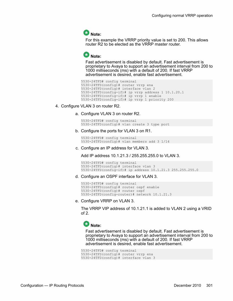
Note:For this example the VRRP priority value is set to 200. This allowsrouter R2 to be elected as the VRRP master router.
Note:Fast advertisement is disabled by default. Fast advertisement isproprietary to Avaya to support an advertisement interval from 200 to1000 milliseconds (ms) with a default of 200. If fast VRRPadvertisement is desired, enable fast advertisement.
5530-24TFD# config terminal5530-24TFD(config)# router vrrp ena5530-24TFD(config)# interface vlan 25530-24TFD(config-if)# ip vrrp address 1 10.1.20.1 5530-24TFD(config-if)# ip vrrp 1 enable5530-24TFD(config-if)# ip vrrp 1 priority 200
4. Configure VLAN 3 on router R2.
a. Configure VLAN 3 on router R2.5530-24TFD# config terminal5530-24TFD(config)# vlan create 3 type port
b. Configure the ports for VLAN 3 on R1.5530-24TFD# config terminal5530-24TFD(config)# vlan members add 3 1/14
c. Configure an IP address for VLAN 3.
Add IP address 10.1.21.3 / 255.255.255.0 to VLAN 3.5530-24TFD# config terminal5530-24TFD(config)# interface vlan 35530-24TFD(config-if)# ip address 10.1.21.3 255.255.255.0
d. Configure an OSPF interface for VLAN 3.5530-24TFD# config terminal5530-24TFD(config)# router ospf enable5530-24TFD(config)# router ospf5530-24TFD(config-router)# network 10.1.21.3
e. Configure VRRP on VLAN 3.
The VRRP VIP address of 10.1.21.1 is added to VLAN 2 using a VRIDof 2.
Note:Fast advertisement is disabled by default. Fast advertisement isproprietary to Avaya to support an advertisement interval from 200 to1000 milliseconds (ms) with a default of 200. If fast VRRPadvertisement is desired, enable fast advertisement.
5530-24TFD# config terminal5530-24TFD(config)# router vrrp ena5530-24TFD(config)# interface vlan 3
Configuring normal VRRP operation
Configuration — IP Routing Protocols December 2010 301
5530-24TFD(config-if)# ip vrrp address 2 10.1.21.15530-24TFD(config-if)# ip vrrp 2 enable
After the VRRP configuration has been completed, use the show ip vrrp and show ipvrrp interface verbose commands to display VRRP configuration information andstatistics.
Configuration command listingThis following list is a complete sequence of the commands used in this configuration:
1. VLAN Configuration for Router R1
config t vlan create 2 type port vlan members remove 2 1/1-1/14,2/1-2/8,3/1-3/8 vlan members add 2 1/15 interface vlan 2 ip address 10.1.20.2 255.255.255.0 router ospf enable router ospf network 10.1.20.2 router vrrp ena interface vlan 2 ip vrrp address 1 10.1.20.1 ip vrrp 1 enable vlan create 3 type port interface vlan 3 ip address 10.1.21.2 255.255.255.0 router ospf enable router ospf network 10.1.21.2 router vrrp ena interface vlan 3 ip vrrp address 2 10.1.21.1 ip vrrp 2 priority 200 ip vrrp 2 enable
2. VLAN Configuration for Router R2
config t vlan create 2 type port vlan members remove 2 1/1-1/14,2/1-2/8,3/1-3/8 vlan members add 2 1/15 interface vlan 2 ip address 10.1.20.3 255.255.255.0 router ospf enable router ospf network 10.1.20.3 router vrrp ena interface vlan 2 ip vrrp address 1 10.1.20.1 ip vrrp 1 priority 200 ip vrrp 1 enable vlan create 3 type port vlan members remove 3 1/1-1/14,1/15,2/1-2/8,3/1-3/8 vlan members add 3 1/14 interface vlan 3 ip address 10.1.21.3 255.255.255.0 router ospf enable router ospf network 10.1.21.3 router vrrp ena interface vlan 3 ip vrrp address 2 10.1.21.1 ip vrrp 2 enable
Configuring VRRP with SMLTThis configuration example shows how you can provide high availability for a Layer 2 edgeswitch feeding into a Layer 3 core. As demonstrated below, both R1 and R2 switches areconfigured with a port-based VLAN (VLAN 2) with SMLT and VRRP set to enabled. Thistopology provides failover protection and load-balancing.
The Avaya Ethernet Routing Switch 5000 Series (E1), running in Layer 2 mode, is configuredwith one port-based VLAN and one Multi-Link Trunking (MLT) group for the aggregate uplinkports. The Avaya Ethernet Routing Switch 5000 Series switches (R1 and R2) are configuredwith backup master enabled so that both switches can reply to ARP.
VRRP configuration examples using ACLI
302 Configuration — IP Routing Protocols December 2010
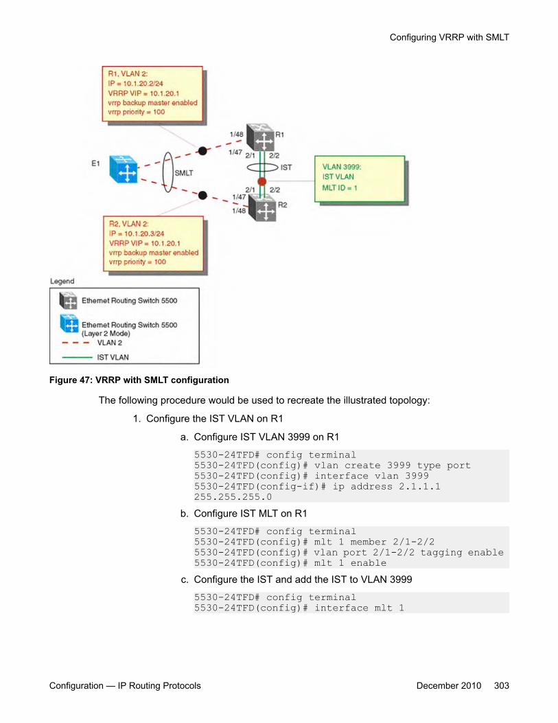
Figure 47: VRRP with SMLT configuration
The following procedure would be used to recreate the illustrated topology:
1. Configure the IST VLAN on R1
a. Configure IST VLAN 3999 on R1
5530-24TFD# config terminal5530-24TFD(config)# vlan create 3999 type port 5530-24TFD(config)# interface vlan 3999 5530-24TFD(config-if)# ip address 2.1.1.1 255.255.255.0
b. Configure IST MLT on R1
5530-24TFD# config terminal 5530-24TFD(config)# mlt 1 member 2/1-2/2 5530-24TFD(config)# vlan port 2/1-2/2 tagging enable 5530-24TFD(config)# mlt 1 enable
c. Configure the IST and add the IST to VLAN 3999
5530-24TFD# config terminal 5530-24TFD(config)# interface mlt 1
Configuring VRRP with SMLT
Configuration — IP Routing Protocols December 2010 303
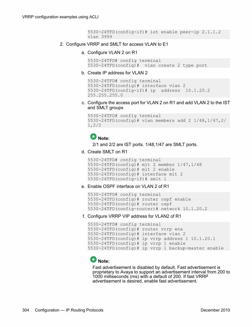
5530-24TFD(config-if)# ist enable peer-ip 2.1.1.2 vlan 3999
2. Configure VRRP and SMLT for access VLAN to E1
a. Configure VLAN 2 on R1
5530-24TFD# config terminal 5530-24TFD(config)# vlan create 2 type port
b. Create IP address for VLAN 2
5530-24TFD# config terminal 5530-24TFD(config)# interface vlan 2 5530-24TFD(config-if)# ip address 10.1.20.2 255.255.255.0
c. Configure the access port for VLAN 2 on R1 and add VLAN 2 to the ISTand SMLT groups
5530-24TFD# config terminal 5530-24TFD(config)# vlan members add 2 1/48,1/47,2/1,2/2
Note:2/1 and 2/2 are IST ports. 1/48,1/47 are SMLT ports.
d. Create SMLT on R1
5530-24TFD# config terminal 5530-24TFD(config)# mlt 2 member 1/47,1/48 5530-24TFD(config)# mlt 2 enable 5530-24TFD(config)# interface mlt 2 5530-24TFD(config-if)# smlt 1
e. Enable OSPF interface on VLAN 2 of R1
5530-24TFD# config terminal 5530-24TFD(config)# router ospf enable 5530-24TFD(config)# router ospf 5530-24TFD(config-router)# network 10.1.20.2
f. Configure VRRP VIP address for VLAN2 of R1
5530-24TFD# config terminal 5530-24TFD(config)# router vrrp ena 5530-24TFD(config)# interface vlan 2 5530-24TFD(config)# ip vrrp address 1 10.1.20.1 5530-24TFD(config)# ip vrrp 1 enable 5530-24TFD(config)# ip vrrp 1 backup-master enable
Note:Fast advertisement is disabled by default. Fast advertisement isproprietary to Avaya to support an advertisement interval from 200 to1000 milliseconds (ms) with a default of 200. If fast VRRPadvertisement is desired, enable fast advertisement.
VRRP configuration examples using ACLI
304 Configuration — IP Routing Protocols December 2010

3. Configure the IST VLAN for router R2
a. Configure IST VLAN 3999 on R2
5530-24TFD# config terminal 5530-24TFD(config)# vlan create 3999 type port 5530-24TFD(config)# interface vlan 3999 5530-24TFD(config-if)# ip address 2.1.1.2 255.255.255.0
b. Configure IST MLT on R2
5530-24TFD# config terminal 5530-24TFD(config)# mlt 1 member 2/1-2/2 5530-24TFD(config)# mlt 1 enable 5530-24TFD(config)# vlan port 2/1-2/2 tagging enable
c. Configure an IST peer for R2 and add the IST to VLAN 3999
5530-24TFD# config terminal 5530-24TFD(config)# interface mlt 1 5530-24TFD(config-if)# ist enable peer-ip 2.1.1.2 vlan 3999
4. Configure VRRP and SMLT for VLAN access to E1
a. Configure VLAN 2 on R2
5530-24TFD# config terminal 5530-24TFD(config)# vlan create 2 type port
b. Create an IP address for VLAN 2
5530-24TFD# config terminal 5530-24TFD(config)# interface vlan 2 5530-24TFD(config-if)# ip address 10.1.20.3 255.255.255.0
c. Configure the access port for VLAN 2 on R2 and add VLAN 2 to the ISTand SMLT groups
5530-24TFD# config terminal 5530-24TFD(config)# vlan members add 2 1/47, 1/48, 2/1. 2/2
Note:1/47 and 1/48 are SMLT ports. 2/1 and 2/2 are IST ports.
d. Create SMLT on R2
5530-24TFD# config terminal 5530-24TFD(config)# mlt 2 member 1/47, 1/48 5530-24TFD(config)# mlt 2 enable 5530-24TFD(config)# interface mlt 2 5530-24TFD(config-if)# smlt 1
e. Enable OSPF interface for VLAN 2 on R2
5530-24TFD# config terminal 5530-24TFD(config)# router ospf enable
Configuring VRRP with SMLT
Configuration — IP Routing Protocols December 2010 305
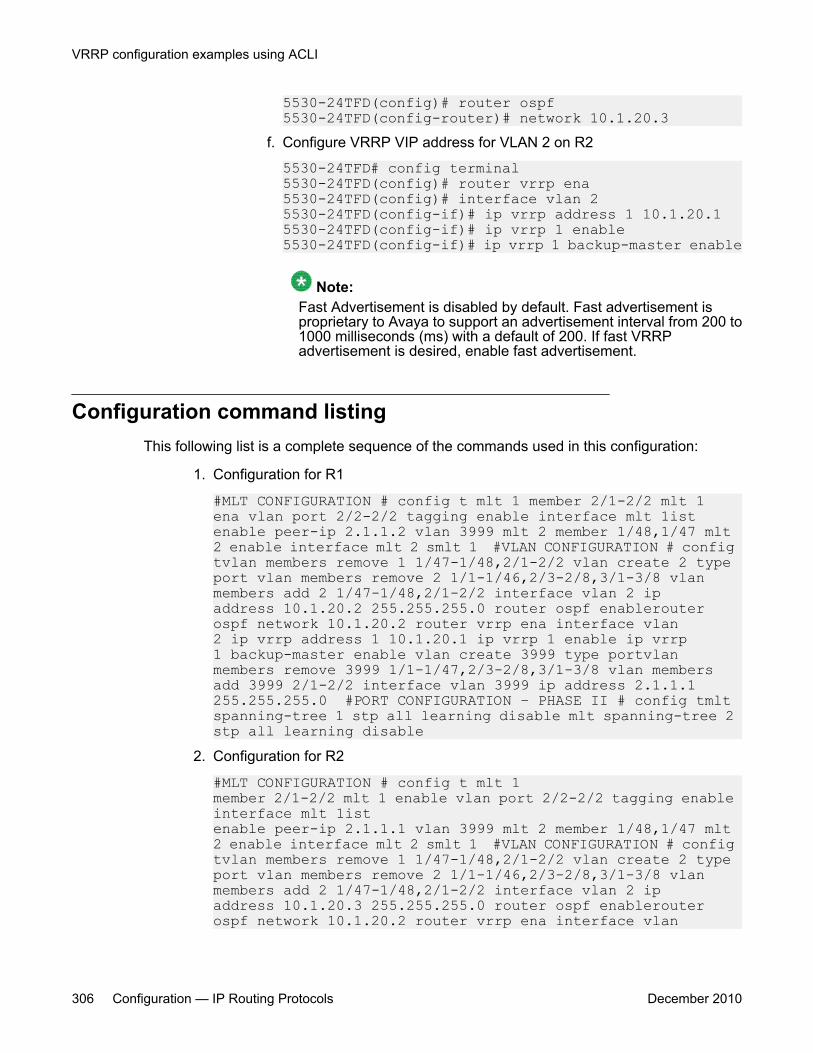
5530-24TFD(config)# router ospf 5530-24TFD(config-router)# network 10.1.20.3
f. Configure VRRP VIP address for VLAN 2 on R2
5530-24TFD# config terminal 5530-24TFD(config)# router vrrp ena 5530-24TFD(config)# interface vlan 2 5530-24TFD(config-if)# ip vrrp address 1 10.1.20.1 5530-24TFD(config-if)# ip vrrp 1 enable 5530-24TFD(config-if)# ip vrrp 1 backup-master enable
Note:Fast Advertisement is disabled by default. Fast advertisement isproprietary to Avaya to support an advertisement interval from 200 to1000 milliseconds (ms) with a default of 200. If fast VRRPadvertisement is desired, enable fast advertisement.
Configuration command listingThis following list is a complete sequence of the commands used in this configuration:
1. Configuration for R1
#MLT CONFIGURATION # config t mlt 1 member 2/1-2/2 mlt 1 ena vlan port 2/2-2/2 tagging enable interface mlt 1istenable peer-ip 2.1.1.2 vlan 3999 mlt 2 member 1/48,1/47 mlt 2 enable interface mlt 2 smlt 1 #VLAN CONFIGURATION # config tvlan members remove 1 1/47-1/48,2/1-2/2 vlan create 2 type port vlan members remove 2 1/1-1/46,2/3-2/8,3/1-3/8 vlan members add 2 1/47-1/48,2/1-2/2 interface vlan 2 ip address 10.1.20.2 255.255.255.0 router ospf enablerouter ospf network 10.1.20.2 router vrrp ena interface vlan 2 ip vrrp address 1 10.1.20.1 ip vrrp 1 enable ip vrrp 1 backup-master enable vlan create 3999 type portvlan members remove 3999 1/1-1/47,2/3-2/8,3/1-3/8 vlan members add 3999 2/1-2/2 interface vlan 3999 ip address 2.1.1.1 255.255.255.0 #PORT CONFIGURATION – PHASE II # config tmlt spanning-tree 1 stp all learning disable mlt spanning-tree 2 stp all learning disable
2. Configuration for R2
#MLT CONFIGURATION # config t mlt 1 member 2/1-2/2 mlt 1 enable vlan port 2/2-2/2 tagging enable interface mlt 1ist enable peer-ip 2.1.1.1 vlan 3999 mlt 2 member 1/48,1/47 mlt 2 enable interface mlt 2 smlt 1 #VLAN CONFIGURATION # config tvlan members remove 1 1/47-1/48,2/1-2/2 vlan create 2 type port vlan members remove 2 1/1-1/46,2/3-2/8,3/1-3/8 vlan members add 2 1/47-1/48,2/1-2/2 interface vlan 2 ip address 10.1.20.3 255.255.255.0 router ospf enablerouter ospf network 10.1.20.2 router vrrp ena interface vlan
VRRP configuration examples using ACLI
306 Configuration — IP Routing Protocols December 2010
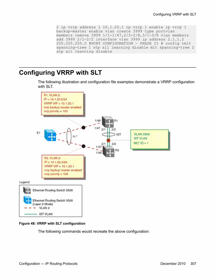
2 ip vrrp address 1 10.1.20.1 ip vrrp 1 enable ip vrrp 1 backup-master enable vlan create 3999 type portvlan members remove 3999 1/1-1/47,2/3-2/8,3/1-3/8 vlan members add 3999 2/1-2/2 interface vlan 3999 ip address 2.1.1.2 255.255.255.0 #PORT CONFIGURATION – PHASE II # config tmlt spanning-tree 1 stp all learning disable mlt spanning-tree 2 stp all learning disable
Configuring VRRP with SLTThe following illustration and configuration file examples demonstrate a VRRP configurationwith SLT.
Figure 48: VRRP with SLT configuration
The following commands would recreate the above configuration:
Configuring VRRP with SLT
Configuration — IP Routing Protocols December 2010 307

1. Configuration for R1
#MLT CONFIGURATION # config t mlt 1 member 2/1-2/2 mlt 1 enable vlan port 2/2-2/2 tagging enable interface mlt 1 ist enable peer-ip 2.1.1.2 vlan 3999 interface fast-Ethernet 1/48 smlt 1 #VLAN CONFIGURATION # config tvlan members remove 1 1/48,2/1-2/2 vlan create 2 type portvlan members remove 2 1/1-1/47,2/3-2/8,3/1-3/8 vlan members add 2 1/47,2/1-2/2 interface vlan 2 ip address 10.1.20.2 255.255.255.0 router ospf enablerouter ospf network 10.1.20.2 router vrrp ena interface vlan 2 ip vrrp address 1 10.1.20.1 ip vrrp 1 enable ip vrrp 1 backup-master enable vlan create 3999 type port vlan members remove 3999 1/1-1/47,2/3-2/8,3/1-3/8 vlan members add 3999 2/1-2/2 interface vlan 3999 ip address 2.1.1.1 255.255.255.0 #PORT CONFIGURATION – PHASE II # config tmlt spanning-tree 1 stp all learning disable interface fast-Ethernet 1/48 spanning-tree stp 1 learning disable
2. Configuration for R2
#MLT CONFIGURATION # config t mlt 1 member 2/1-2/2mlt 1 enable vlan port 2/2-2/2 tagging enable interface mlt 1ist enable peer-ip 2.1.1.1 vlan 3999 interface fast-Ethernet 1/48 smlt 1 #VLAN CONFIGURATION # config tvlan members remove 1 1/48,2/1-2/2 vlan create 2 type portvlan members remove 2 1/1-1/47,2/3-2/8,3/1-3/8 vlan members add 2 1/48,2/1-2/2 interface vlan 2 ip address 10.1.20.3 255.255.255.0 router ospf enablerouter ospf network 10.1.20.2 router vrrp ena interface vlan 2 ip vrrp address 1 10.1.20.1 ip vrrp 1 enable ip vrrp 1 backup-master enable vlan create 3999 type portvlan members remove 3999 1/1-1/47,2/3-2/8,3/1-3/8vlan members add 3999 2/1-2/2 interface vlan 3999 ip address 2.1.1.2 255.255.255.0 #PORT CONFIGURATION – PHASE II # config tmlt spanning-tree 1 stp all learning disable interface fast-Ethernet 1/48 spanning-tree stp 1 learning disable
VRRP configuration examples using ACLI
308 Configuration — IP Routing Protocols December 2010

Chapter 22: IGMP snooping configurationusing ACLI
This chapter describes the procedures you can use to configure IGMP snooping on a VLAN using ACLI.
IGMP snooping configuration proceduresTo configure IGMP snooping, the only required configuration is to enable snooping onthe VLAN.
All related configurations, listed below, are optional and can be configured to suit therequirements of your network.
IGMP snooping configuration navigation• Job aid: Roadmap of IGMP ACLI commands on page 310
• Configuring IGMP snooping on a VLAN on page 312
• Configuring IGMP send query on a VLAN on page 313
• Configuring IGMP proxy on a VLAN on page 314
• Configuring the IGMP version on a VLAN on page 315
• Configuring static mrouter ports on a VLAN on page 316
• Displaying IGMP snoop, proxy, and mrouter configuration on page 317
• Configuring IGMP parameters on a VLAN on page 317
• Configuring the router alert option on a VLAN on page 319
• Displaying IGMP interface information on page 320
• Displaying IGMP group information using EDM on page 488
• Configuring unknown multicast packet filtering on page 323
• Displaying the status of unknown multicast packet filtering on page 324
• Displaying the multicast MAC addresses for which flooding is allowed on page 325
Configuration — IP Routing Protocols December 2010 309
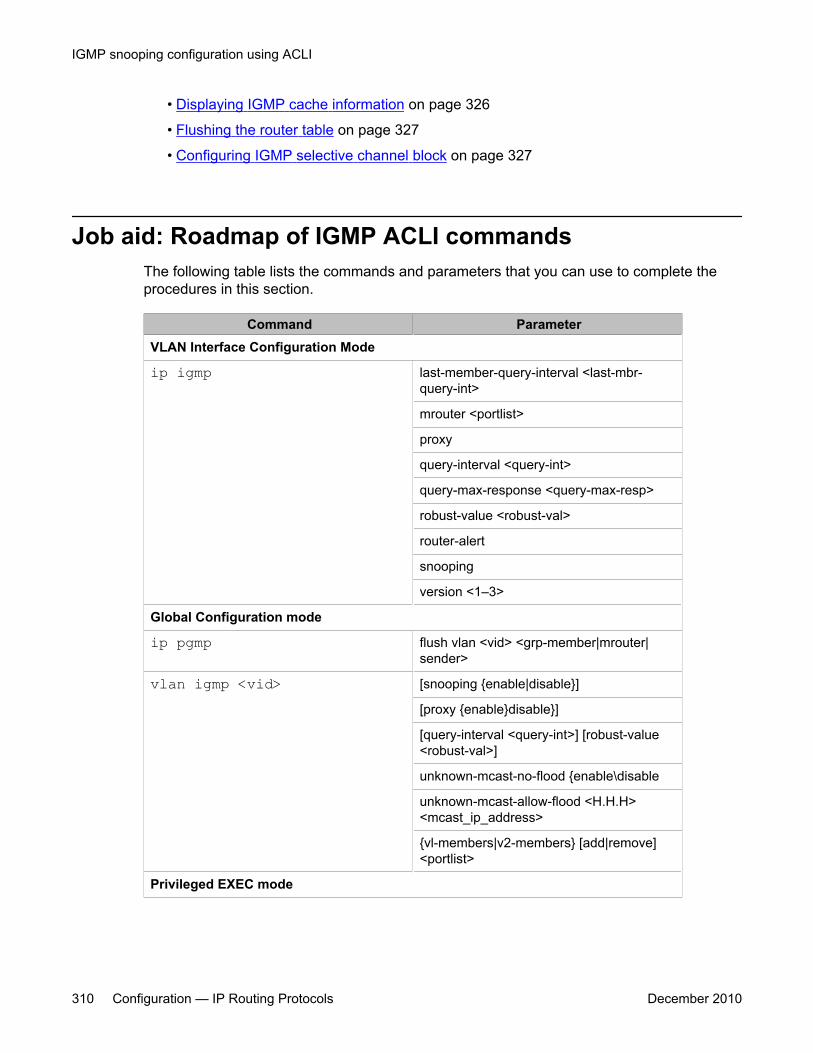
• Displaying IGMP cache information on page 326
• Flushing the router table on page 327
• Configuring IGMP selective channel block on page 327
Job aid: Roadmap of IGMP ACLI commandsThe following table lists the commands and parameters that you can use to complete theprocedures in this section.
Command ParameterVLAN Interface Configuration Mode
ip igmp last-member-query-interval <last-mbr-query-int>
mrouter <portlist>
proxy
query-interval <query-int>
query-max-response <query-max-resp>
robust-value <robust-val>
router-alert
snooping
version <1–3>
Global Configuration mode
ip pgmp flush vlan <vid> <grp-member|mrouter|sender>
vlan igmp <vid> [snooping {enable|disable}]
[proxy {enable}disable}]
[query-interval <query-int>] [robust-value<robust-val>]
unknown-mcast-no-flood {enable\disable
unknown-mcast-allow-flood <H.H.H><mcast_ip_address>
{vl-members|v2-members} [add|remove]<portlist>
Privileged EXEC mode
IGMP snooping configuration using ACLI
310 Configuration — IP Routing Protocols December 2010
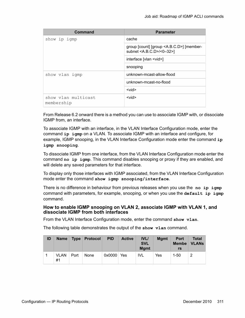
Command Parametershow ip igmp cache
group [count] [group <A.B.C.D>] [member-subnet <A.B.C.D>/<0–32>]
interface [vlan <vid>]
snooping
show vlan igmp unknown-mcast-allow-flood
unknown-mcast-no-flood
<vid>
show vlan multicastmembership
<vid>
From Release 6.2 onward there is a method you can use to associate IGMP with, or dissociateIGMP from, an interface.
To associate IGMP with an interface, in the VLAN Interface Configuration mode, enter thecommand ip igmp on a VLAN. To associate IGMP with an interface and configure, forexample, IGMP snooping, in the VLAN Interface Configuration mode enter the command ipigmp snooping.
To dissociate IGMP from one interface, from the VLAN Interface Configuration mode enter thecommand no ip igmp. This command disables snooping or proxy if they are enabled, andwill delete any saved parameters for that interface.
To display only those interfaces with IGMP associated, from the VLAN Interface Configurationmode enter the command show igmp snooping/interface.
There is no difference in behaviour from previous releases when you use the no ip igmpcommand with parameters, for example, snooping, or when you use the default ip igmpcommand.
How to enable IGMP snooping on VLAN 2, associate IGMP with VLAN 1, anddissociate IGMP from both interfacesFrom the VLAN Interface Configuration mode, enter the command show vlan.
The following table demonstrates the output of the show vlan command.
ID Name Type Protocol PID Active IVL/SVL
Mgmt
Mgmt PortMembe
rs
TotalVLANs
1 VLAN#1
Port None 0x0000 Yes IVL Yes 1-50 2
Job aid: Roadmap of IGMP ACLI commands
Configuration — IP Routing Protocols December 2010 311
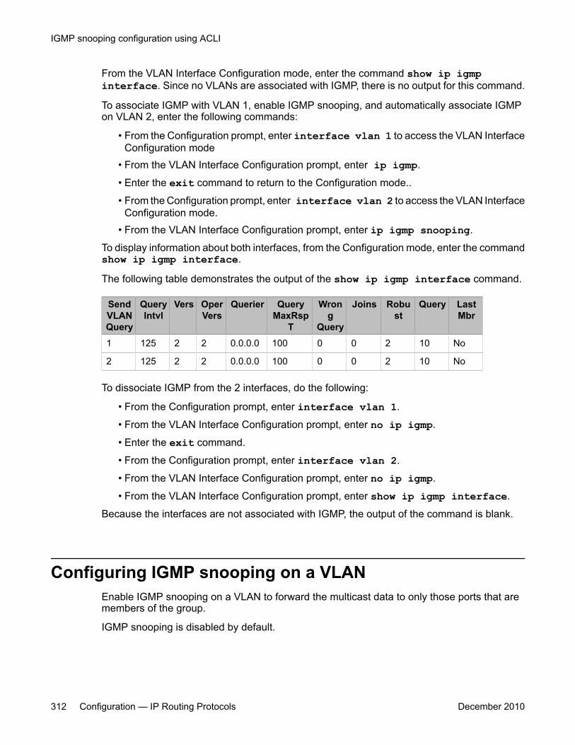
From the VLAN Interface Configuration mode, enter the command show ip igmpinterface. Since no VLANs are associated with IGMP, there is no output for this command.
To associate IGMP with VLAN 1, enable IGMP snooping, and automatically associate IGMPon VLAN 2, enter the following commands:
• From the Configuration prompt, enter interface vlan 1 to access the VLAN InterfaceConfiguration mode
• From the VLAN Interface Configuration prompt, enter ip igmp.
• Enter the exit command to return to the Configuration mode..
• From the Configuration prompt, enter interface vlan 2 to access the VLAN InterfaceConfiguration mode.
• From the VLAN Interface Configuration prompt, enter ip igmp snooping.
To display information about both interfaces, from the Configuration mode, enter the commandshow ip igmp interface.
The following table demonstrates the output of the show ip igmp interface command.
SendVLANQuery
QueryIntvl
Vers OperVers
Querier QueryMaxRsp
T
Wrong
Query
Joins Robust
Query LastMbr
1 125 2 2 0.0.0.0 100 0 0 2 10 No
2 125 2 2 0.0.0.0 100 0 0 2 10 No
To dissociate IGMP from the 2 interfaces, do the following:
• From the Configuration prompt, enter interface vlan 1.
• From the VLAN Interface Configuration prompt, enter no ip igmp.
• Enter the exit command.
• From the Configuration prompt, enter interface vlan 2.
• From the VLAN Interface Configuration prompt, enter no ip igmp.
• From the VLAN Interface Configuration prompt, enter show ip igmp interface.
Because the interfaces are not associated with IGMP, the output of the command is blank.
Configuring IGMP snooping on a VLANEnable IGMP snooping on a VLAN to forward the multicast data to only those ports that aremembers of the group.
IGMP snooping is disabled by default.
IGMP snooping configuration using ACLI
312 Configuration — IP Routing Protocols December 2010

Procedure steps
To enable IGMP snooping, enter the following from the VLAN Interface Configurationcommand mode:
[default] [no] ip igmp snoopingOR
Enter the following from the Global Configuration command mode:
[default] vlan igmp <vid> [snooping {enable | disable}]
Variable definitionsThe following table describes the command variables.
Variable Valuedefault Disables IGMP snooping on the selected VLAN.
no Disables IGMP snooping on the selected VLAN.
enable Enables IGMP snooping on the selected VLAN.
disable Disables IGMP snooping on the selected VLAN.
Configuring IGMP send query on a VLANUse this procedure to enable IGMP send query on a snoop-enabled VLAN. When IGMPsnooping send query is enabled, the IGMP snooping querier sends out periodic IGMP queriesthat trigger IGMP report messages from the switch or host that wants to receive IP multicasttraffic. IGMP snooping listens to these IGMP reports to establish appropriate forwarding.
IGMP send query is disabled by default.
Configuring IGMP send query on a VLAN
Configuration — IP Routing Protocols December 2010 313
Prerequisites
You must enable snoop on the VLAN.
Procedure steps
To enable IGMP send query, enter the following command from the VLAN InterfaceConfiguration mode:
ip igmp send-query
Configuring IGMP proxy on a VLANUse this procedure to enable IGMP proxy on a snoop-enabled VLAN. With IGMP proxyenabled, the switch consolidates incoming report messages into one proxy report for thatgroup.
IGMP proxy is disabled by default.
Prerequisites
You must enable snoop on the VLAN.
Procedure steps
To enable IGMP proxy, enter the following from the VLAN Interface Configurationmode:
[default] [no] ip igmp proxyOR
Enter the following from the Global Configuration command mode:
IGMP snooping configuration using ACLI
314 Configuration — IP Routing Protocols December 2010
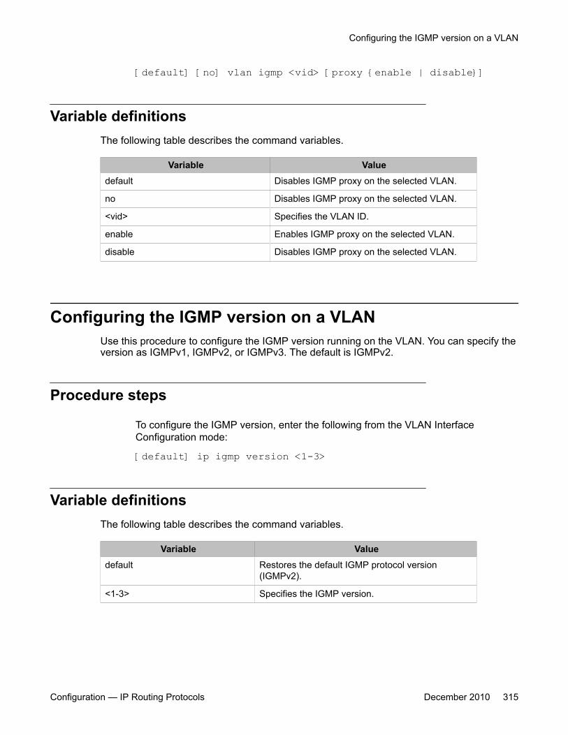
[default] [no] vlan igmp <vid> [proxy {enable | disable}]
Variable definitionsThe following table describes the command variables.
Variable Valuedefault Disables IGMP proxy on the selected VLAN.
no Disables IGMP proxy on the selected VLAN.
<vid> Specifies the VLAN ID.
enable Enables IGMP proxy on the selected VLAN.
disable Disables IGMP proxy on the selected VLAN.
Configuring the IGMP version on a VLANUse this procedure to configure the IGMP version running on the VLAN. You can specify theversion as IGMPv1, IGMPv2, or IGMPv3. The default is IGMPv2.
Procedure steps
To configure the IGMP version, enter the following from the VLAN InterfaceConfiguration mode:
[default] ip igmp version <1-3>
Variable definitionsThe following table describes the command variables.
Variable Valuedefault Restores the default IGMP protocol version
(IGMPv2).
<1-3> Specifies the IGMP version.
Configuring the IGMP version on a VLAN
Configuration — IP Routing Protocols December 2010 315
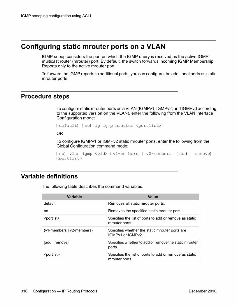
Configuring static mrouter ports on a VLANIGMP snoop considers the port on which the IGMP query is received as the active IGMPmulticast router (mrouter) port. By default, the switch forwards incoming IGMP MembershipReports only to the active mrouter port.
To forward the IGMP reports to additional ports, you can configure the additional ports as staticmrouter ports.
Procedure steps
To configure static mrouter ports on a VLAN (IGMPv1, IGMPv2, and IGMPv3 accordingto the supported version on the VLAN), enter the following from the VLAN InterfaceConfiguration mode:
[default] [no] ip igmp mrouter <portlist>OR
To configure IGMPv1 or IGMPv2 static mrouter ports, enter the following from theGlobal Configuration command mode:
[no] vlan igmp <vid> {v1-members | v2-members} [add | remove]<portlist>
Variable definitionsThe following table describes the command variables.
Variable Valuedefault Removes all static mrouter ports.
no Removes the specified static mrouter port.
<portlist> Specifies the list of ports to add or remove as staticmrouter ports.
{v1-members | v2-members} Specifies whether the static mrouter ports areIGMPv1 or IGMPv2.
[add | remove] Specifies whether to add or remove the static mrouterports.
<portlist> Specifies the list of ports to add or remove as staticmrouter ports.
IGMP snooping configuration using ACLI
316 Configuration — IP Routing Protocols December 2010
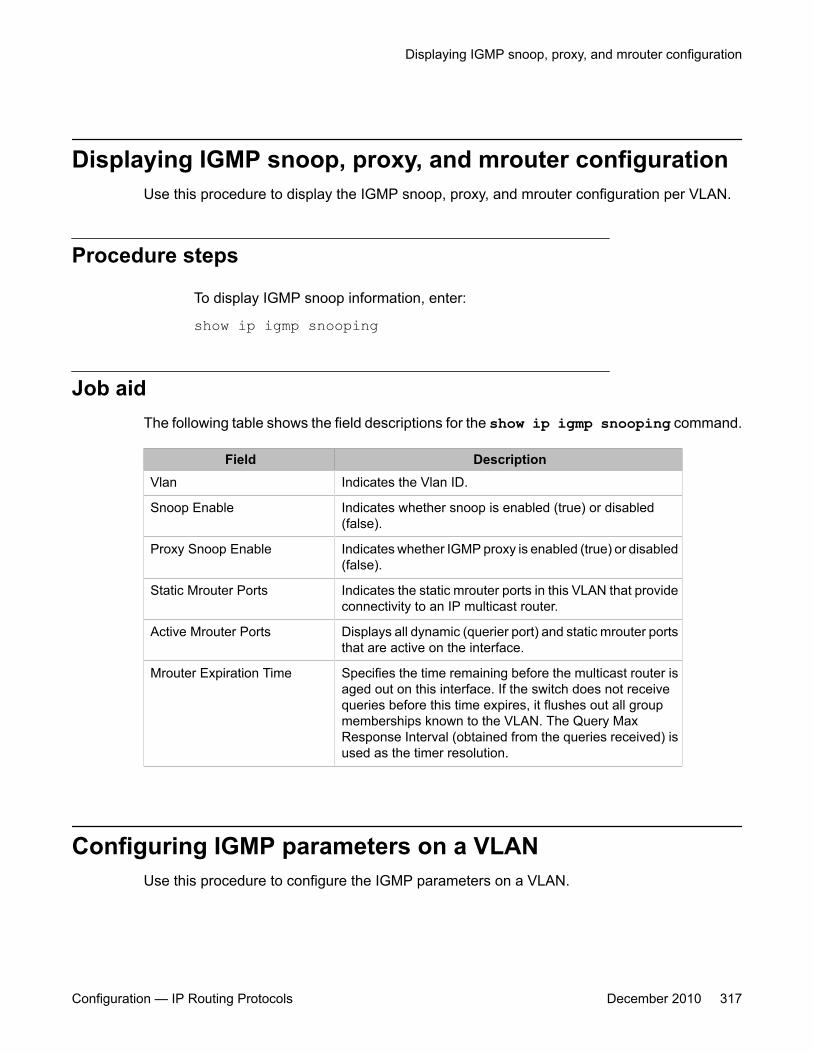
Displaying IGMP snoop, proxy, and mrouter configurationUse this procedure to display the IGMP snoop, proxy, and mrouter configuration per VLAN.
Procedure steps
To display IGMP snoop information, enter:
show ip igmp snooping
Job aidThe following table shows the field descriptions for the show ip igmp snooping command.
Field DescriptionVlan Indicates the Vlan ID.
Snoop Enable Indicates whether snoop is enabled (true) or disabled(false).
Proxy Snoop Enable Indicates whether IGMP proxy is enabled (true) or disabled(false).
Static Mrouter Ports Indicates the static mrouter ports in this VLAN that provideconnectivity to an IP multicast router.
Active Mrouter Ports Displays all dynamic (querier port) and static mrouter portsthat are active on the interface.
Mrouter Expiration Time Specifies the time remaining before the multicast router isaged out on this interface. If the switch does not receivequeries before this time expires, it flushes out all groupmemberships known to the VLAN. The Query MaxResponse Interval (obtained from the queries received) isused as the timer resolution.
Configuring IGMP parameters on a VLANUse this procedure to configure the IGMP parameters on a VLAN.
Displaying IGMP snoop, proxy, and mrouter configuration
Configuration — IP Routing Protocols December 2010 317

Important:The query interval, robustness, and version values must be the same as those configuredon the interface (VLAN) of the multicast router (IGMP querier).
Procedure steps
To configure IGMP parameters, enter the following from the VLAN InterfaceConfiguration mode:[default] ip igmp[last-member-query-interval <last-mbr-query-int>][query-interval <query-int>][query-max-response <query-max-resp>][robust-value <robust-val>][version <1-3>]
OR
enter the following from the Global Configuration command mode:[default] vlan igmp <vid>[query-interval <query-int>][robust-value <robust-val>]
Variable definitionsThe following table describes the command variables.
Variable Valuedefault Sets the selected parameter to the default value. If no parameters are
specified, snoop is disabled and all IGMP parameters are set to theirdefaults.
<last-mbr-query-int>
Sets the maximum response time (in 1/10 seconds) that is inserted intogroup-specific queries sent in response to leave group messages. Thisparameter is also the time between group-specific query messages.This value is not configurable for IGMPv1. Decreasing the valuereduces the time to detect the loss of the last member of a group. Therange is from 0–255, and the default is 10 (1 second). Avayarecommends configuring this parameter to values higher than 3. If afast leave process is not required, Avaya recommends values above10. (The value 3 is equal to 0.3 of a second, and 10 is equal to 1.0second.)
<query-int> Sets the frequency (in seconds) at which host query packets aretransmitted on the VLAN. The range is 1–65535. The default value is125 seconds.
IGMP snooping configuration using ACLI
318 Configuration — IP Routing Protocols December 2010
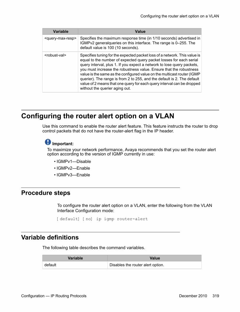
Variable Value<query-max-resp> Specifies the maximum response time (in 1/10 seconds) advertised in
IGMPv2 generalqueries on this interface. The range is 0–255. Thedefault value is 100 (10 seconds).
<robust-val> Specifies tuning for the expected packet loss of a network. This value isequal to the number of expected query packet losses for each serialquery interval, plus 1. If you expect a network to lose query packets,you must increase the robustness value. Ensure that the robustnessvalue is the same as the configured value on the multicast router (IGMPquerier). The range is from 2 to 255, and the default is 2. The defaultvalue of 2 means that one query for each query interval can be droppedwithout the querier aging out.
Configuring the router alert option on a VLANUse this command to enable the router alert feature. This feature instructs the router to dropcontrol packets that do not have the router-alert flag in the IP header.
Important:To maximize your network performance, Avaya recommends that you set the router alertoption according to the version of IGMP currently in use:
• IGMPv1—Disable• IGMPv2—Enable• IGMPv3—Enable
Procedure steps
To configure the router alert option on a VLAN, enter the following from the VLANInterface Configuration mode:
[default] [no] ip igmp router-alert
Variable definitionsThe following table describes the command variables.
Variable Valuedefault Disables the router alert option.
Configuring the router alert option on a VLAN
Configuration — IP Routing Protocols December 2010 319
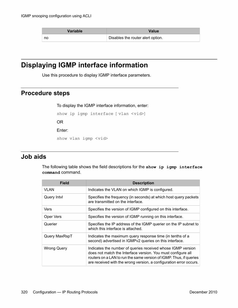
Variable Valueno Disables the router alert option.
Displaying IGMP interface informationUse this procedure to display IGMP interface parameters.
Procedure steps
To display the IGMP interface information, enter:
show ip igmp interface [vlan <vid>]OR
Enter:
show vlan igmp <vid>
Job aidsThe following table shows the field descriptions for the show ip igmp interfacecommand command.
Field DescriptionVLAN Indicates the VLAN on which IGMP is configured.
Query Intvl Specifies the frequency (in seconds) at which host query packetsare transmitted on the interface.
Vers Specifies the version of IGMP configured on this interface.
Oper Vers Specifies the version of IGMP running on this interface.
Querier Specifies the IP address of the IGMP querier on the IP subnet towhich this interface is attached.
Query MaxRspT Indicates the maximum query response time (in tenths of asecond) advertised in IGMPv2 queries on this interface.
Wrong Query Indicates the number of queries received whose IGMP versiondoes not match the Interface version. You must configure allrouters on a LAN to run the same version of IGMP. Thus, if queriesare received with the wrong version, a configuration error occurs.
IGMP snooping configuration using ACLI
320 Configuration — IP Routing Protocols December 2010
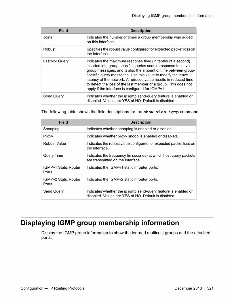
Field DescriptionJoins Indicates the number of times a group membership was added
on this interface.
Robust Specifies the robust value configured for expected packet loss onthe interface.
LastMbr Query Indicates the maximum response time (in tenths of a second)inserted into group-specific queries sent in response to leavegroup messages, and is also the amount of time between group-specific query messages. Use this value to modify the leavelatency of the network. A reduced value results in reduced timeto detect the loss of the last member of a group. This does notapply if the interface is configured for IGMPv1.
Send Query Indicates whether the ip igmp send-query feature is enabled ordisabled. Values are YES of NO. Default is disabled.
The following table shows the field descriptions for the show vlan igmp command.
Field DescriptionSnooping Indicates whether snooping is enabled or disabled.
Proxy Indicates whether proxy snoop is enabled or disabled.
Robust Value Indicates the robust value configured for expected packet loss onthe interface.
Query Time Indicates the frequency (in seconds) at which host query packetsare transmitted on the interface.
IGMPv1 Static RouterPorts
Indicates the IGMPv1 static mrouter ports.
IGMPv2 Static RouterPorts
Indicates the IGMPv2 static mrouter ports.
Send Query Indicates whether the ip igmp send-query feature is enabled ordisabled. Values are YES of NO. Default is disabled.
Displaying IGMP group membership informationDisplay the IGMP group information to show the learned multicast groups and the attachedports.
Displaying IGMP group membership information
Configuration — IP Routing Protocols December 2010 321
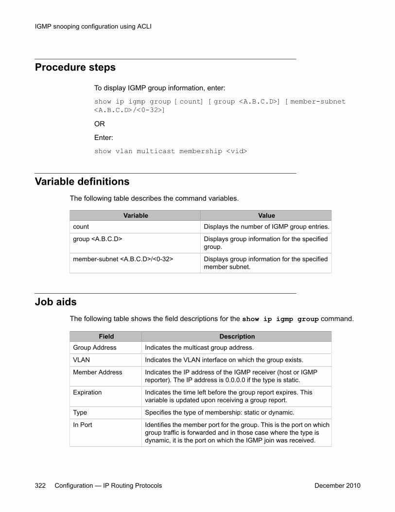
Procedure steps
To display IGMP group information, enter:
show ip igmp group [count] [group <A.B.C.D>] [member-subnet<A.B.C.D>/<0-32>]OR
Enter:
show vlan multicast membership <vid>
Variable definitionsThe following table describes the command variables.
Variable Valuecount Displays the number of IGMP group entries.
group <A.B.C.D> Displays group information for the specifiedgroup.
member-subnet <A.B.C.D>/<0-32> Displays group information for the specifiedmember subnet.
Job aidsThe following table shows the field descriptions for the show ip igmp group command.
Field DescriptionGroup Address Indicates the multicast group address.
VLAN Indicates the VLAN interface on which the group exists.
Member Address Indicates the IP address of the IGMP receiver (host or IGMPreporter). The IP address is 0.0.0.0 if the type is static.
Expiration Indicates the time left before the group report expires. Thisvariable is updated upon receiving a group report.
Type Specifies the type of membership: static or dynamic.
In Port Identifies the member port for the group. This is the port on whichgroup traffic is forwarded and in those case where the type isdynamic, it is the port on which the IGMP join was received.
IGMP snooping configuration using ACLI
322 Configuration — IP Routing Protocols December 2010
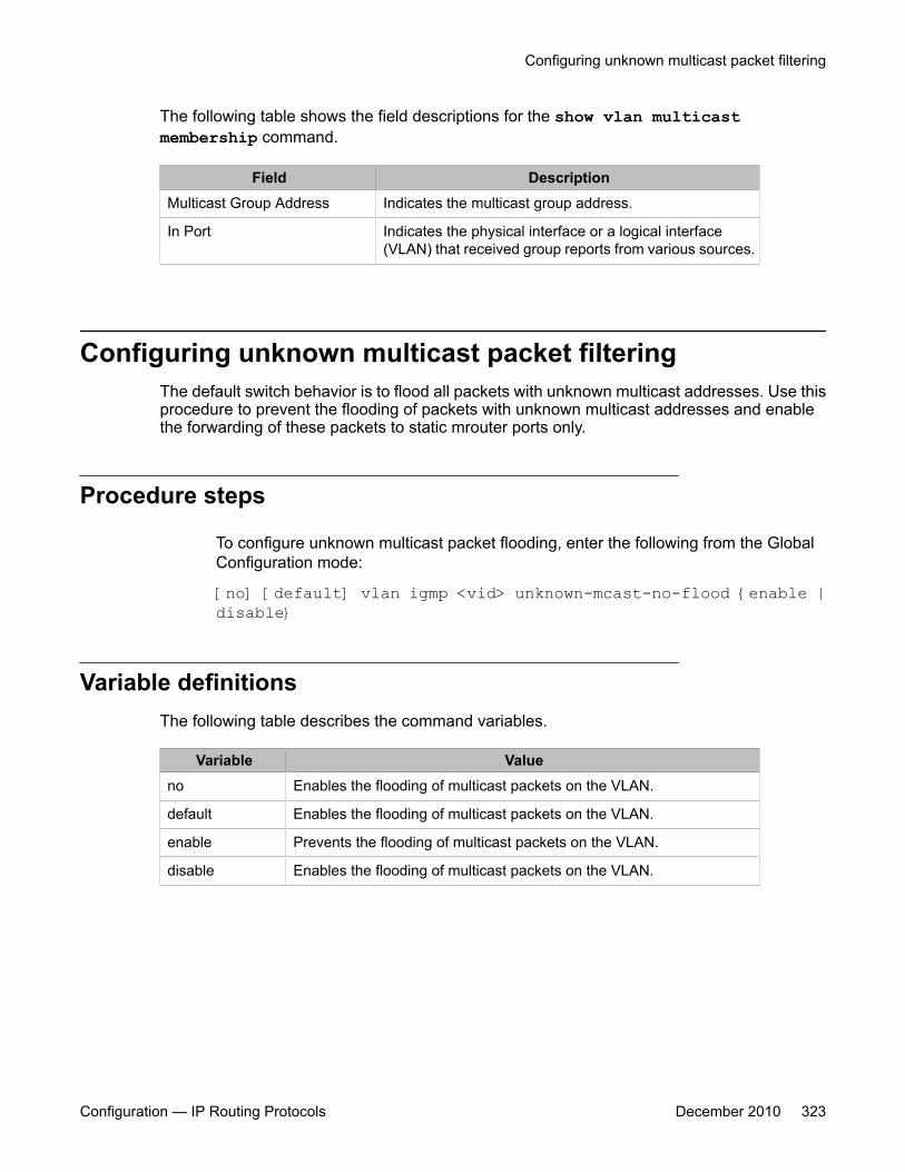
The following table shows the field descriptions for the show vlan multicastmembership command.
Field DescriptionMulticast Group Address Indicates the multicast group address.
In Port Indicates the physical interface or a logical interface(VLAN) that received group reports from various sources.
Configuring unknown multicast packet filteringThe default switch behavior is to flood all packets with unknown multicast addresses. Use thisprocedure to prevent the flooding of packets with unknown multicast addresses and enablethe forwarding of these packets to static mrouter ports only.
Procedure steps
To configure unknown multicast packet flooding, enter the following from the GlobalConfiguration mode:
[no] [default] vlan igmp <vid> unknown-mcast-no-flood {enable |disable}
Variable definitionsThe following table describes the command variables.
Variable Valueno Enables the flooding of multicast packets on the VLAN.
default Enables the flooding of multicast packets on the VLAN.
enable Prevents the flooding of multicast packets on the VLAN.
disable Enables the flooding of multicast packets on the VLAN.
Configuring unknown multicast packet filtering
Configuration — IP Routing Protocols December 2010 323
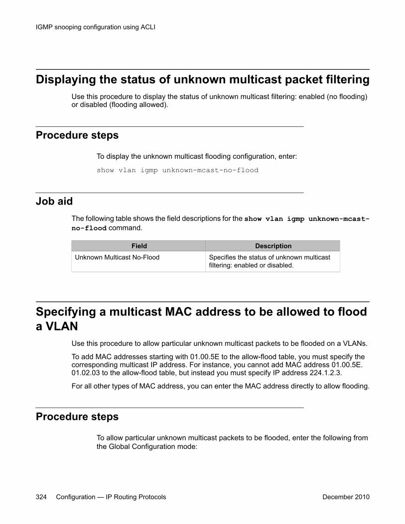
Displaying the status of unknown multicast packet filteringUse this procedure to display the status of unknown multicast filtering: enabled (no flooding)or disabled (flooding allowed).
Procedure steps
To display the unknown multicast flooding configuration, enter:
show vlan igmp unknown-mcast-no-flood
Job aidThe following table shows the field descriptions for the show vlan igmp unknown-mcast-no-flood command.
Field DescriptionUnknown Multicast No-Flood Specifies the status of unknown multicast
filtering: enabled or disabled.
Specifying a multicast MAC address to be allowed to flooda VLAN
Use this procedure to allow particular unknown multicast packets to be flooded on a VLANs.
To add MAC addresses starting with 01.00.5E to the allow-flood table, you must specify thecorresponding multicast IP address. For instance, you cannot add MAC address 01.00.5E.01.02.03 to the allow-flood table, but instead you must specify IP address 224.1.2.3.
For all other types of MAC address, you can enter the MAC address directly to allow flooding.
Procedure steps
To allow particular unknown multicast packets to be flooded, enter the following fromthe Global Configuration mode:
IGMP snooping configuration using ACLI
324 Configuration — IP Routing Protocols December 2010

vlan igmp unknown-mcast-allow-flood <vid> {<H.H.H> |<mcast_ip_address>}
Variable definitionsThe following table describes the command variables.
Variable Value<vid> Specifies the VLAN on which to configure the flooding.
<H.H.H> Specifies the multicast MAC address to be flooded. Acceptedformats are:
• H.H.H
• xx:xx:xx:xx:xx:xx
• xx.xx.xx.xx.xx.xx
• xx-xx-xx-xx-xx-xx
<mcast_ip_address> Specifies the multicast IP address to be flooded.
Displaying the multicast MAC addresses for which floodingis allowed
Use this procedure to display the multicast MAC addresses for which flooding is allowed onall switch VLANs.
Procedure steps
To display the multicast MAC addresses for which flooding is allowed, enter:
show vlan igmp unknown-mcast-allow-flood
Job aidThe following table shows the field descriptions for the show vlan igmp unknown-mcast-allow-flood command.
Displaying the multicast MAC addresses for which flooding is allowed
Configuration — IP Routing Protocols December 2010 325

Field DescriptionAllowed Multicast Addresses Indicates multicast addresses that can flood.
Displaying IGMP cache informationDisplay the IGMP cache information to show the learned multicast groups in the cache andthe IGMPv1 version timers.
Note:Using the show ip igmp cache command may not display the expected results in someconfigurations. If the expected results are not displayed, use the show ip igmp groupcommand to view the information.
Procedure steps
To display the IGMP cache information, enter:
show ip igmp cache
Job aidThe following table shows the field descriptions for the show ip igmp cache command.
Field DescriptionGroup Address Indicates the multicast group address.
Vlan ID Indicates the VLAN interface on which the group exists.
Last Reporter Indicates the last IGMP host to join the group.
Expiration Indicates the group expiration time (in seconds).
V1 Host Timer Indicates the time remaining until the local router assumes that noIGMP version 1 members exist on the IP subnet attached to theinterface. Upon hearing an IGMPv1 membership report, this valueis reset to the group membership timer. When the time remainingis nonzero, the local interface ignores IGMPv2 Leave messagesthat it receives for this group.
Type Indicates whether the entry is learned dynamically or is addedstatically.
IGMP snooping configuration using ACLI
326 Configuration — IP Routing Protocols December 2010
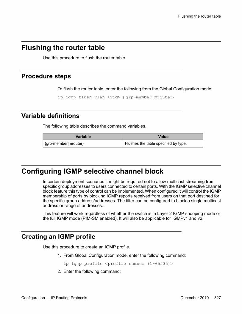
Flushing the router tableUse this procedure to flush the router table.
Procedure steps
To flush the router table, enter the following from the Global Configuration mode:
ip igmp flush vlan <vid> {grp-member|mrouter}
Variable definitionsThe following table describes the command variables.
Variable Value{grp-member|mrouter} Flushes the table specified by type.
Configuring IGMP selective channel blockIn certain deployment scenarios it might be required not to allow multicast streaming fromspecific group addresses to users connected to certain ports. With the IGMP selective channelblock feature this type of control can be implemented. When configured it will control the IGMPmembership of ports by blocking IGMP reports received from users on that port destined forthe specific group address/addresses. The filter can be configured to block a single multicastaddress or range of addresses.
This feature will work regardless of whether the switch is in Layer 2 IGMP snooping mode orthe full IGMP mode (PIM-SM enabled). It will also be applicable for IGMPv1 and v2.
Creating an IGMP profileUse this procedure to create an IGMP profile.
1. From Global Configuration mode, enter the following command:
ip igmp profile <profile number (1-65535)>2. Enter the following command:
Flushing the router table
Configuration — IP Routing Protocols December 2010 327
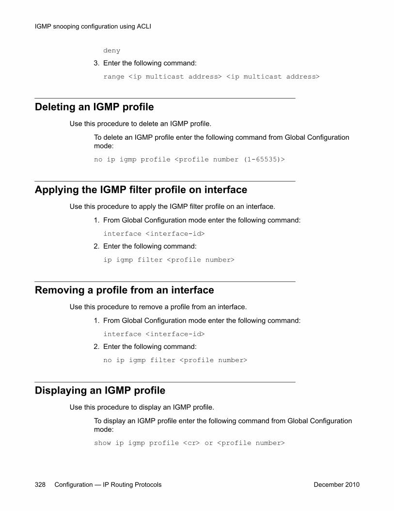
deny3. Enter the following command:
range <ip multicast address> <ip multicast address>
Deleting an IGMP profileUse this procedure to delete an IGMP profile.
To delete an IGMP profile enter the following command from Global Configurationmode:
no ip igmp profile <profile number (1-65535)>
Applying the IGMP filter profile on interfaceUse this procedure to apply the IGMP filter profile on an interface.
1. From Global Configuration mode enter the following command:
interface <interface-id>2. Enter the following command:
ip igmp filter <profile number>
Removing a profile from an interfaceUse this procedure to remove a profile from an interface.
1. From Global Configuration mode enter the following command:
interface <interface-id>2. Enter the following command:
no ip igmp filter <profile number>
Displaying an IGMP profileUse this procedure to display an IGMP profile.
To display an IGMP profile enter the following command from Global Configurationmode:
show ip igmp profile <cr> or <profile number>
IGMP snooping configuration using ACLI
328 Configuration — IP Routing Protocols December 2010
Chapter 23: PIM configuration using ACLI
This chapter describes the procedures you can use to configure PIM-SM using ACLI.
This chapter also describes the procedures you can use to configure PIM-SSM using ACLI.
Unlike dense-mode protocols, such as DVMRP that initially flood multicast traffic to all routers over anentire internetwork, PIM sends multicast traffic only to routers that belong to a specific multicast groupand that choose to receive the traffic. PIM reduces overhead costs for processing unwanted multicastpackets.
Prerequisites for PIM configurationBefore you can configure PIM, you must prepare the switch as follows:
1. Install the Advanced Routing software license.
Important:If your Ethernet Routing Switch is running an Advanced License for a releaseprior to Release 6.0, to enable PIM-SM you must regenerate your license file fromthe Avaya web site and install the new license file on the switch.
2. Enable routing globally.
3. Configure IP addresses and enable routing on the VLAN interfaces on which youwant to configure PIM-SM.
4. Enable a unicast protocol, either RIP or OSPF, globally and on the interfaces onwhich you want to configure PIM.
Important:PIM requires a unicast protocol to multicast traffic within the network whenperforming the Reverse Path Forwarding (RPF) check. PIM also uses theinformation from the unicast routing table to create and maintain the shared andshortest path multicast tree. The unicast routing table must contain a route toevery multicast source in the network, as well as routes to PIM entities such asthe rendezvous points (RP) and bootstrap router (BSR).
Configuration — IP Routing Protocols December 2010 329
PIM configuration proceduresTo configure PIM-SM, you must perform the following procedures:
1. Enable PIM globally.
(If desired, modify the default global PIM properties.)
2. Enable PIMon individual VLAN interfaces.
(If desired, modify the default VLAN PIM properties.)
3. For PIM-SM, configure candidate RPs for the multicast groups in the network. (It isbest to have multiple candidate-RPs in the network; however, with the EthernetRouting Switch 5000, you can only configure one candidate-RP per switch for anynumber of groups.)
OR
Configure one (or several) static RPs for the multicast groups in the network. (Toenable static RP in the PIM-SM domain, you must configure the same static RPson every system that takes part in PIM-SM forwarding.)
4. For PIM-SM, configure one or several candidate BSRs to propagate RP informationto all switches in the network. (You can configure every PIM-enabled VLAN as a C-BSR. If Static RP is enabled, this step is not required.)
Important:Ensure that all routers in the path from the receivers to the RP and to the multicastsource are PIM-enabled. Also ensure that all PIM routers have unicast routes toreach the source and RP through directly-connected PIM neighbors.
All additional configurations listed below are optional and can be configured according to therequirements of your network.
PIM configuration navigation• Job aid: Roadmap of PIM configuration commands on page 331
• Enabling and disabling PIM-SM globally on page 333
• Configuring global PIM-SM properties on page 333
• Enabling PIM-SM on a VLAN on page 336
• Configuring the PIM-SM interface type on a VLAN on page 336
PIM configuration using ACLI
330 Configuration — IP Routing Protocols December 2010
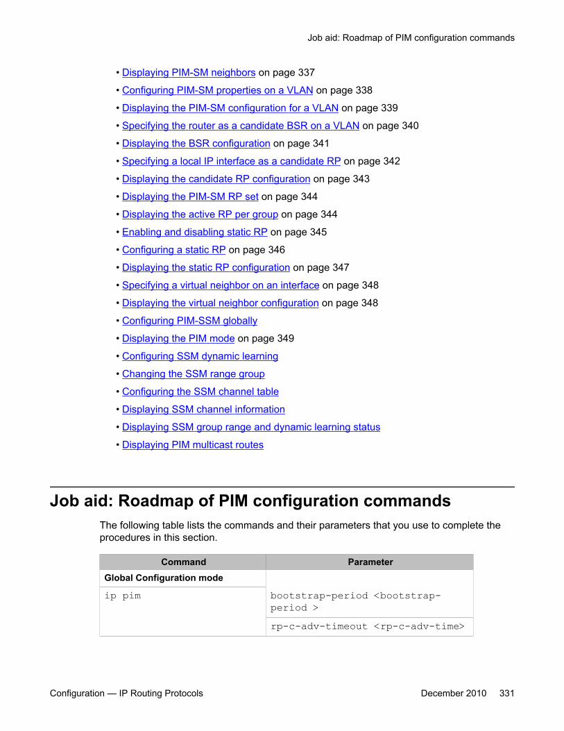
• Displaying PIM-SM neighbors on page 337
• Configuring PIM-SM properties on a VLAN on page 338
• Displaying the PIM-SM configuration for a VLAN on page 339
• Specifying the router as a candidate BSR on a VLAN on page 340
• Displaying the BSR configuration on page 341
• Specifying a local IP interface as a candidate RP on page 342
• Displaying the candidate RP configuration on page 343
• Displaying the PIM-SM RP set on page 344
• Displaying the active RP per group on page 344
• Enabling and disabling static RP on page 345
• Configuring a static RP on page 346
• Displaying the static RP configuration on page 347
• Specifying a virtual neighbor on an interface on page 348
• Displaying the virtual neighbor configuration on page 348
• Configuring PIM-SSM globally
• Displaying the PIM mode on page 349
• Configuring SSM dynamic learning
• Changing the SSM range group
• Configuring the SSM channel table
• Displaying SSM channel information
• Displaying SSM group range and dynamic learning status
• Displaying PIM multicast routes
Job aid: Roadmap of PIM configuration commandsThe following table lists the commands and their parameters that you use to complete theprocedures in this section.
Command ParameterGlobal Configuration mode
ip pim bootstrap-period <bootstrap-period >rp-c-adv-timeout <rp-c-adv-time>
Job aid: Roadmap of PIM configuration commands
Configuration — IP Routing Protocols December 2010 331
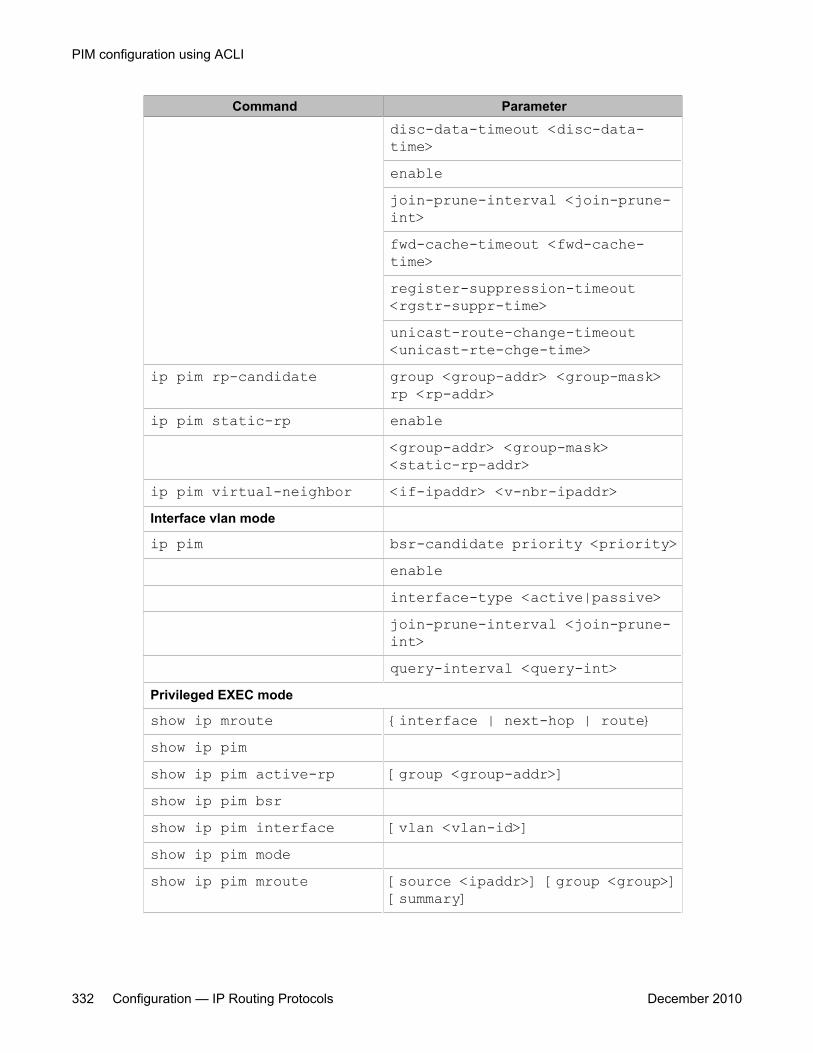
Command Parameterdisc-data-timeout <disc-data-time>enablejoin-prune-interval <join-prune-int>fwd-cache-timeout <fwd-cache-time>register-suppression-timeout<rgstr-suppr-time>unicast-route-change-timeout<unicast-rte-chge-time>
ip pim rp-candidate group <group-addr> <group-mask>rp <rp-addr>
ip pim static-rp enable<group-addr> <group-mask><static-rp-addr>
ip pim virtual-neighbor <if-ipaddr> <v-nbr-ipaddr>Interface vlan mode
ip pim bsr-candidate priority <priority>enableinterface-type <active|passive>join-prune-interval <join-prune-int>query-interval <query-int>
Privileged EXEC mode
show ip mroute {interface | next-hop | route}show ip pimshow ip pim active-rp [group <group-addr>]show ip pim bsrshow ip pim interface [vlan <vlan-id>]show ip pim modeshow ip pim mroute [source <ipaddr>] [group <group>]
[summary]
PIM configuration using ACLI
332 Configuration — IP Routing Protocols December 2010
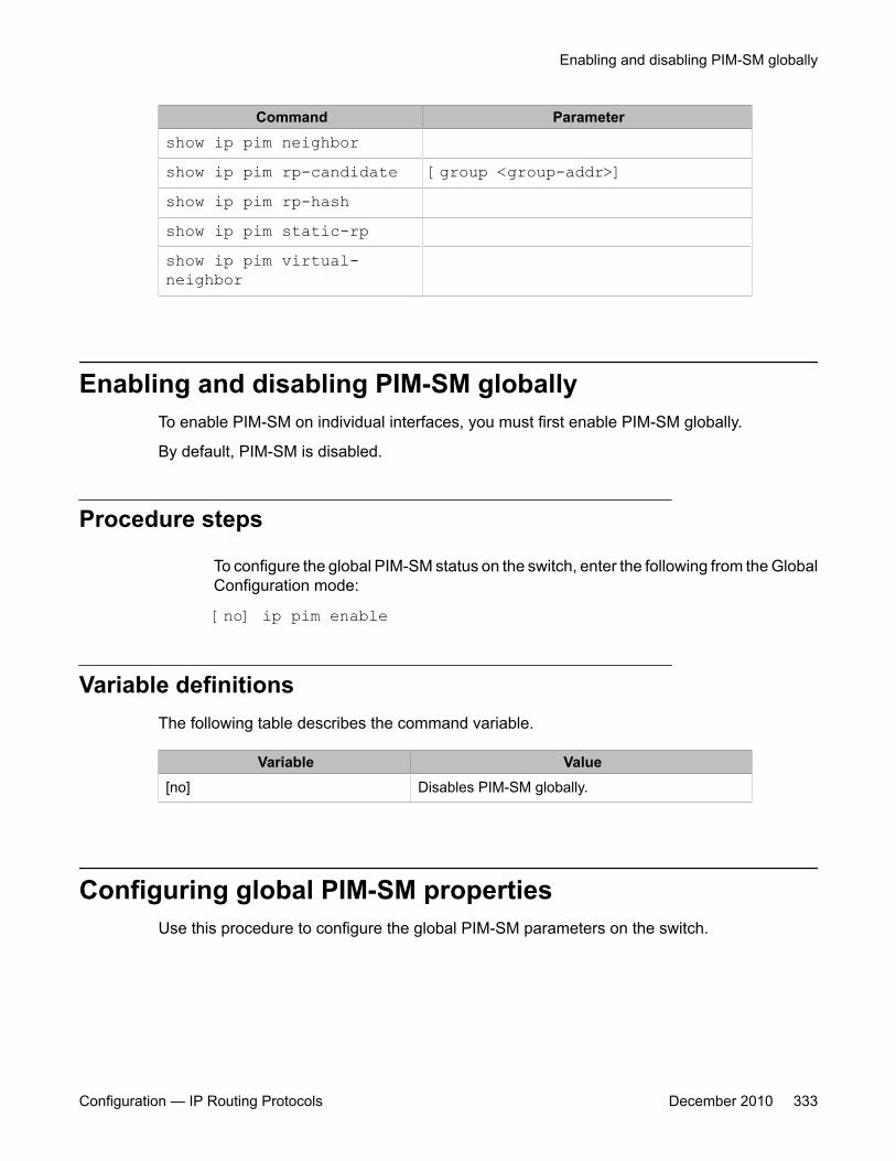
Command Parametershow ip pim neighborshow ip pim rp-candidate [group <group-addr>]show ip pim rp-hashshow ip pim static-rpshow ip pim virtual-neighbor
Enabling and disabling PIM-SM globallyTo enable PIM-SM on individual interfaces, you must first enable PIM-SM globally.
By default, PIM-SM is disabled.
Procedure steps
To configure the global PIM-SM status on the switch, enter the following from the GlobalConfiguration mode:
[no] ip pim enable
Variable definitionsThe following table describes the command variable.
Variable Value[no] Disables PIM-SM globally.
Configuring global PIM-SM propertiesUse this procedure to configure the global PIM-SM parameters on the switch.
Enabling and disabling PIM-SM globally
Configuration — IP Routing Protocols December 2010 333

Procedure steps
To configure the global PIM-SM parameters, enter the following from the GlobalConfiguration mode:
ip pimbootstrap-period <bootstrap-period>disc-data-timeout <disc-data-time>fwd-cache-timeout <fwd-cache-time>join-prune-interval <join-prune-int> register-suppression-timeout <rgstr-suppr-time>rp-c-adv-timeout <rp-c-adv-time>unicast-route-change-timeout <unicast-rte-chge-time>
Variable definitionsThe following table describes the command variables.
Variable Value<bootstrap-period> Specifies the interval (in seconds) that the elected BSR waits
between originating bootstrap messages.Range is 5–32757. The default is 60.
<disc-data-time> After the router forwards the first source packet to the RP, thisvalue specifies how long (in seconds) the router discardssubsequent source data while waiting for a join from the RP. AnIPMC discard record is created and deleted after the timerexpires or after a join is received.Range is 5–65535. The default is 60.
<fwd-cache-time> Specifies the forward cache timeout globally. This value is usedin aging PIM-SM mroutes.Range is 10–86400. The default is 210.
<join-prune-int> Specifies how long to wait (in seconds) before the PIM-SMrouter sends out the next join/prune message to the upstreamneighbors.Range is 1–18724. The default is 60.
<rgstr-suppr-time> Specifies the PIM-SM register suppression timeout.Range is 6–65535. The default is 60.
<rp-c-adv-time> Specifies how often (in seconds) candidate RPs (C-RP) sendC-RP advertisement messages. After this timer expires, the C-RP sends an advertisement message to the elected BSR.Range is 5–26214. The default is 60.
<unicast-rte-chge-time> Specifies the PIM-SM unicast route change timeout. Indicateshow often (in seconds) the switch polls the routing table
PIM configuration using ACLI
334 Configuration — IP Routing Protocols December 2010
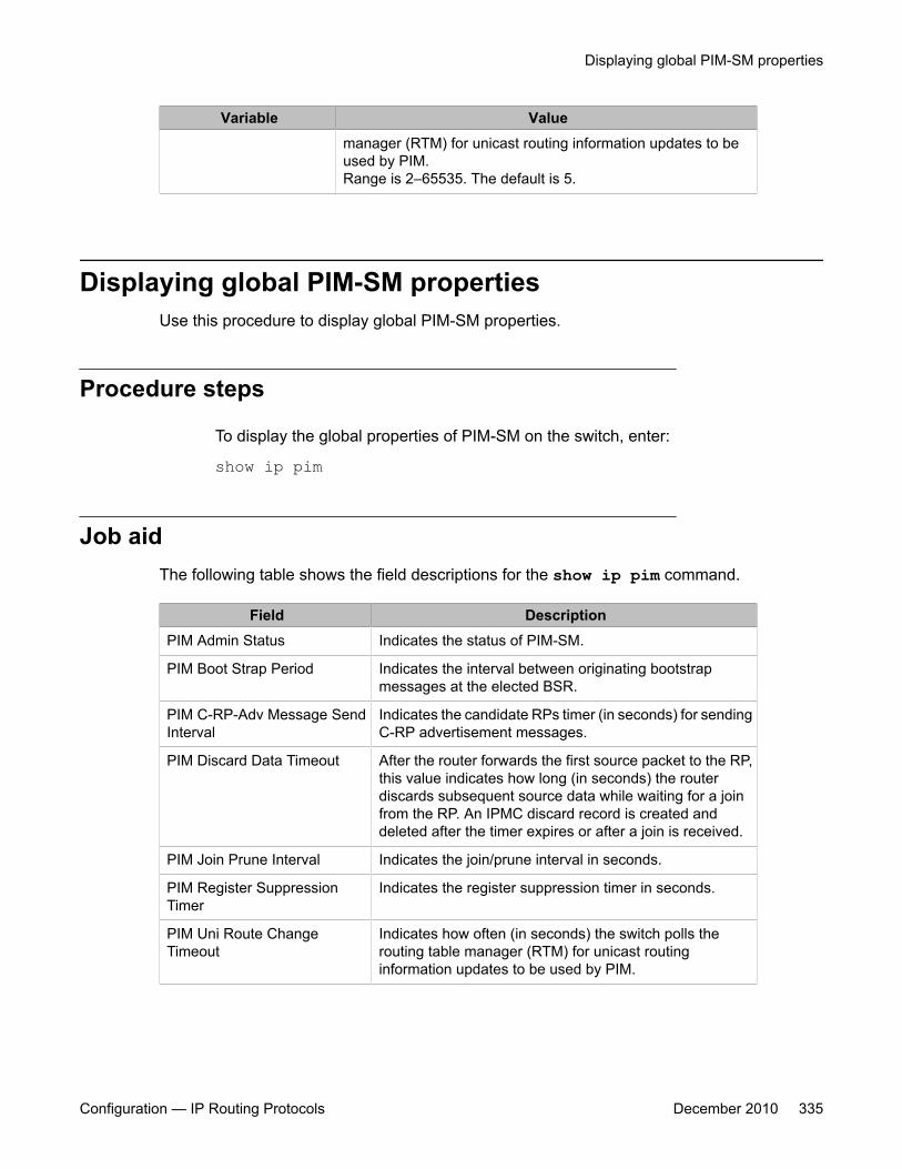
Variable Valuemanager (RTM) for unicast routing information updates to beused by PIM.Range is 2–65535. The default is 5.
Displaying global PIM-SM propertiesUse this procedure to display global PIM-SM properties.
Procedure steps
To display the global properties of PIM-SM on the switch, enter:
show ip pim
Job aidThe following table shows the field descriptions for the show ip pim command.
Field DescriptionPIM Admin Status Indicates the status of PIM-SM.
PIM Boot Strap Period Indicates the interval between originating bootstrapmessages at the elected BSR.
PIM C-RP-Adv Message SendInterval
Indicates the candidate RPs timer (in seconds) for sendingC-RP advertisement messages.
PIM Discard Data Timeout After the router forwards the first source packet to the RP,this value indicates how long (in seconds) the routerdiscards subsequent source data while waiting for a joinfrom the RP. An IPMC discard record is created anddeleted after the timer expires or after a join is received.
PIM Join Prune Interval Indicates the join/prune interval in seconds.
PIM Register SuppressionTimer
Indicates the register suppression timer in seconds.
PIM Uni Route ChangeTimeout
Indicates how often (in seconds) the switch polls therouting table manager (RTM) for unicast routinginformation updates to be used by PIM.
Displaying global PIM-SM properties
Configuration — IP Routing Protocols December 2010 335

Field DescriptionPIM Mode Indicates the PIM mode: sparse mode or source specific
multicast mode.
PIM Static-RP Indicates the status of static RP.
Forward Cache Timeout Indicates the PIM-SM forward cache expiry value inseconds. This value is used in aging PIM-SM mroutes.
Enabling PIM-SM on a VLANUse this procedure to enable PIM-SM on a VLAN.
By default, PIM-SM is disabled on VLANs.
Prerequisites
You must enable PIM-SM globally.
Procedure steps
To configure the PIM-SM status on a particular VLAN, enter the following from theVLAN Interface mode:
[no] ip pim enable
Variable definitionsThe following table describes the command variable.
Variable Value[no] Disables PIM-SM on the VLAN.
Configuring the PIM-SM interface type on a VLANUse this procedure to change the state (active or passive) of PIM on a VLAN interface. Anactive interface transmits and receives PIM control traffic. A passive interface drops all PIM
PIM configuration using ACLI
336 Configuration — IP Routing Protocols December 2010

control traffic, thereby reducing the load on the system. This feature is useful when you havea high number of PIM interfaces and these interfaces are connected to end users, not to otherswitches.
By default, VLANs are active interfaces.
Prerequisites
Before you change the state of PIM on a VLAN interface, you must disable PIM on theinterface to prevent instability in the PIM operations, especially when neighbors are presentor when streams are received.
Procedure steps
To set the interface type on a VLAN, enter the following from the VLAN Interface mode:
ip pim interface-type <active|passive>
Variable definitionsThe following table describes the command variables.
Variable Valueinterface-type <active|passive> Sets the interface type on a particular VLAN:
• active: allows PIM-SM control traffic to be transmittedand received.
• passive: prevents PIM-SM control traffic from beingtransmitted or received, reducing the load on thesystem.
Displaying PIM-SM neighborsUse this procedure to display PIM-SM neighbors.
Displaying PIM-SM neighbors
Configuration — IP Routing Protocols December 2010 337
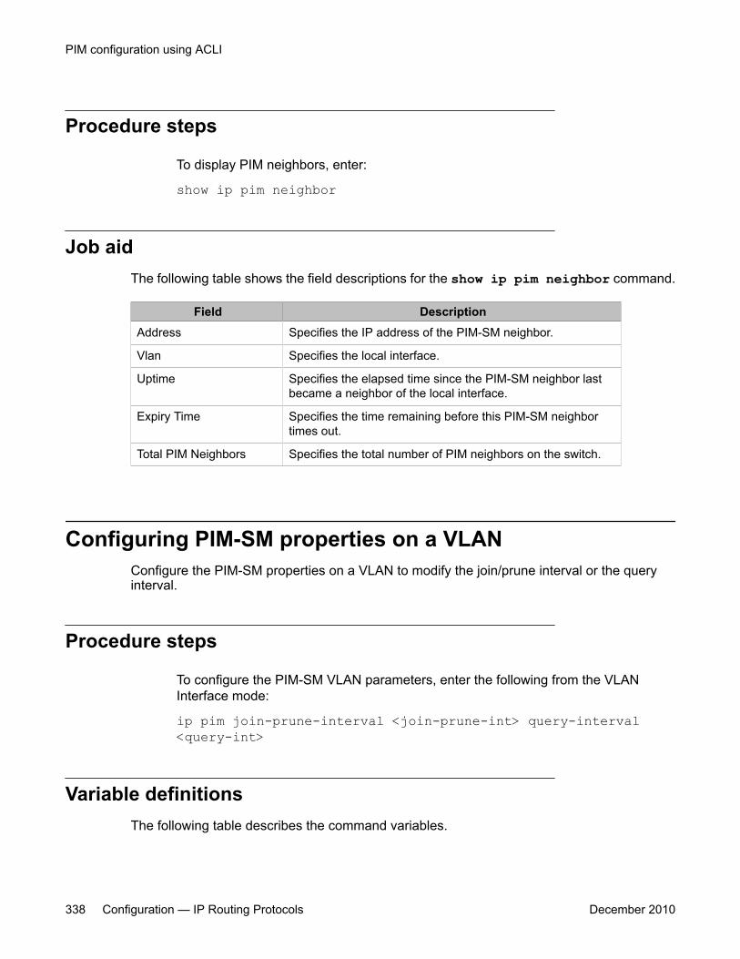
Procedure steps
To display PIM neighbors, enter:
show ip pim neighbor
Job aidThe following table shows the field descriptions for the show ip pim neighbor command.
Field DescriptionAddress Specifies the IP address of the PIM-SM neighbor.
Vlan Specifies the local interface.
Uptime Specifies the elapsed time since the PIM-SM neighbor lastbecame a neighbor of the local interface.
Expiry Time Specifies the time remaining before this PIM-SM neighbortimes out.
Total PIM Neighbors Specifies the total number of PIM neighbors on the switch.
Configuring PIM-SM properties on a VLANConfigure the PIM-SM properties on a VLAN to modify the join/prune interval or the queryinterval.
Procedure steps
To configure the PIM-SM VLAN parameters, enter the following from the VLANInterface mode:
ip pim join-prune-interval <join-prune-int> query-interval<query-int>
Variable definitionsThe following table describes the command variables.
PIM configuration using ACLI
338 Configuration — IP Routing Protocols December 2010
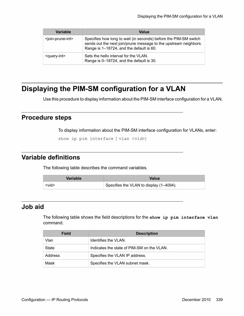
Variable Value<join-prune-int> Specifies how long to wait (in seconds) before the PIM-SM switch
sends out the next join/prune message to the upstream neighbors.Range is 1–18724, and the default is 60.
<query-int> Sets the hello interval for the VLAN.Range is 0–18724, and the default is 30.
Displaying the PIM-SM configuration for a VLANUse this procedure to display information about the PIM-SM interface configuration for a VLAN.
Procedure steps
To display information about the PIM-SM interface configuration for VLANs, enter:
show ip pim interface [vlan <vid>]
Variable definitionsThe following table describes the command variables.
Variable Value<vid> Specifies the VLAN to display (1–4094).
Job aidThe following table shows the field descriptions for the show ip pim interface vlancommand.
Field DescriptionVlan Identifies the VLAN.
State Indicates the state of PIM-SM on the VLAN.
Address Specifies the VLAN IP address.
Mask Specifies the VLAN subnet mask.
Displaying the PIM-SM configuration for a VLAN
Configuration — IP Routing Protocols December 2010 339
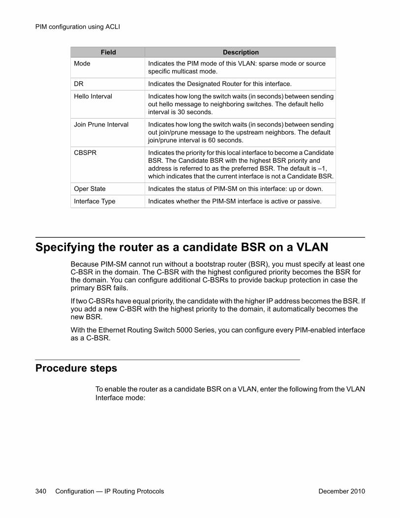
Field DescriptionMode Indicates the PIM mode of this VLAN: sparse mode or source
specific multicast mode.
DR Indicates the Designated Router for this interface.
Hello Interval Indicates how long the switch waits (in seconds) between sendingout hello message to neighboring switches. The default hellointerval is 30 seconds.
Join Prune Interval Indicates how long the switch waits (in seconds) between sendingout join/prune message to the upstream neighbors. The defaultjoin/prune interval is 60 seconds.
CBSPR Indicates the priority for this local interface to become a CandidateBSR. The Candidate BSR with the highest BSR priority andaddress is referred to as the preferred BSR. The default is –1,which indicates that the current interface is not a Candidate BSR.
Oper State Indicates the status of PIM-SM on this interface: up or down.
Interface Type Indicates whether the PIM-SM interface is active or passive.
Specifying the router as a candidate BSR on a VLANBecause PIM-SM cannot run without a bootstrap router (BSR), you must specify at least oneC-BSR in the domain. The C-BSR with the highest configured priority becomes the BSR forthe domain. You can configure additional C-BSRs to provide backup protection in case theprimary BSR fails.
If two C-BSRs have equal priority, the candidate with the higher IP address becomes the BSR. Ifyou add a new C-BSR with the highest priority to the domain, it automatically becomes thenew BSR.
With the Ethernet Routing Switch 5000 Series, you can configure every PIM-enabled interfaceas a C-BSR.
Procedure steps
To enable the router as a candidate BSR on a VLAN, enter the following from the VLANInterface mode:
PIM configuration using ACLI
340 Configuration — IP Routing Protocols December 2010
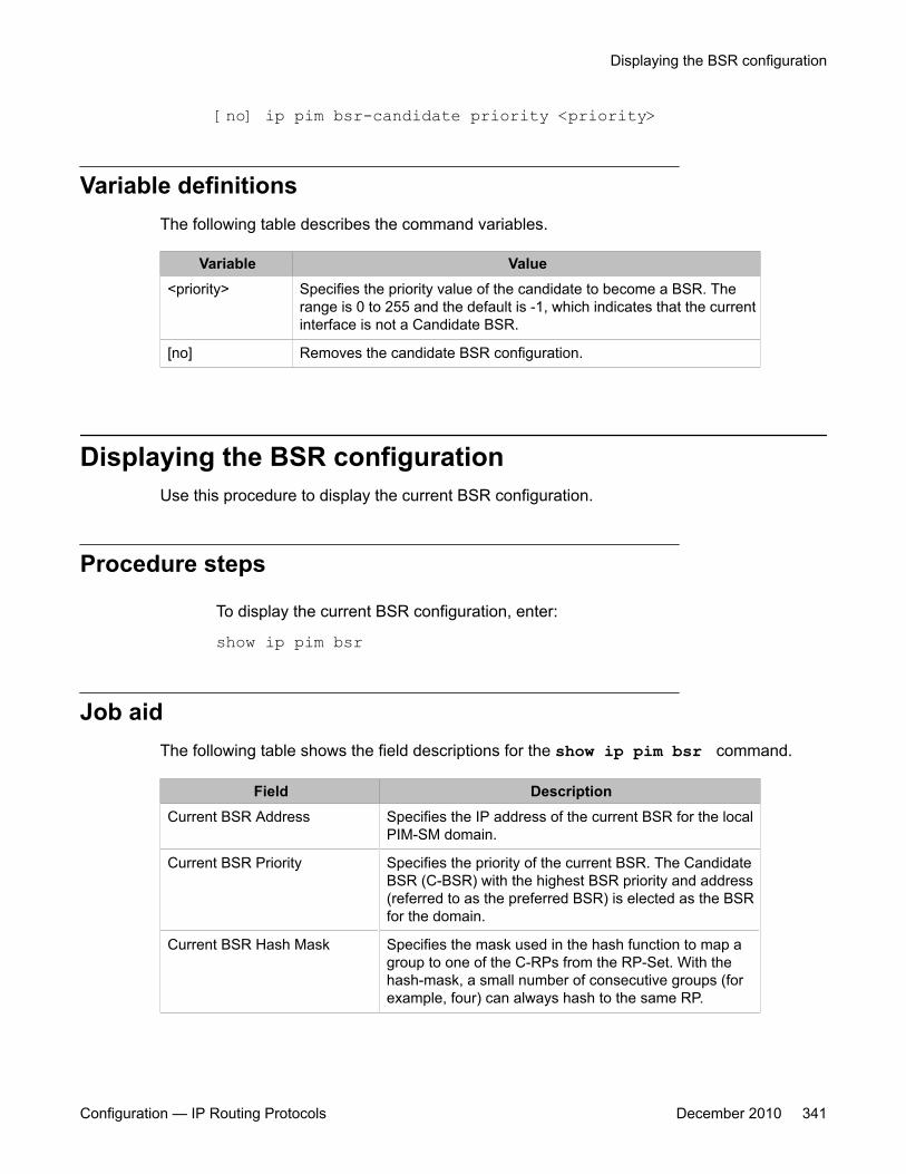
[no] ip pim bsr-candidate priority <priority>
Variable definitionsThe following table describes the command variables.
Variable Value<priority> Specifies the priority value of the candidate to become a BSR. The
range is 0 to 255 and the default is -1, which indicates that the currentinterface is not a Candidate BSR.
[no] Removes the candidate BSR configuration.
Displaying the BSR configurationUse this procedure to display the current BSR configuration.
Procedure steps
To display the current BSR configuration, enter:
show ip pim bsr
Job aidThe following table shows the field descriptions for the show ip pim bsr command.
Field DescriptionCurrent BSR Address Specifies the IP address of the current BSR for the local
PIM-SM domain.
Current BSR Priority Specifies the priority of the current BSR. The CandidateBSR (C-BSR) with the highest BSR priority and address(referred to as the preferred BSR) is elected as the BSRfor the domain.
Current BSR Hash Mask Specifies the mask used in the hash function to map agroup to one of the C-RPs from the RP-Set. With thehash-mask, a small number of consecutive groups (forexample, four) can always hash to the same RP.
Displaying the BSR configuration
Configuration — IP Routing Protocols December 2010 341
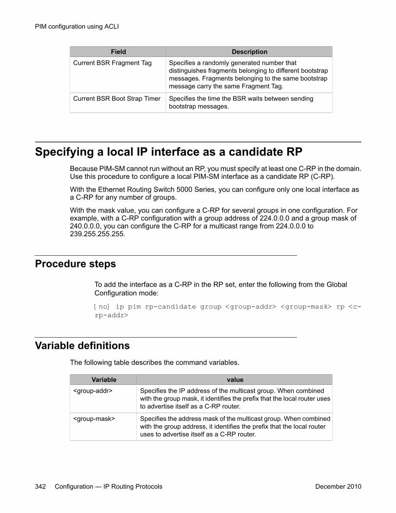
Field DescriptionCurrent BSR Fragment Tag Specifies a randomly generated number that
distinguishes fragments belonging to different bootstrapmessages. Fragments belonging to the same bootstrapmessage carry the same Fragment Tag.
Current BSR Boot Strap Timer Specifies the time the BSR waits between sendingbootstrap messages.
Specifying a local IP interface as a candidate RPBecause PIM-SM cannot run without an RP, you must specify at least one C-RP in the domain.Use this procedure to configure a local PIM-SM interface as a candidate RP (C-RP).
With the Ethernet Routing Switch 5000 Series, you can configure only one local interface asa C-RP for any number of groups.
With the mask value, you can configure a C-RP for several groups in one configuration. Forexample, with a C-RP configuration with a group address of 224.0.0.0 and a group mask of240.0.0.0, you can configure the C-RP for a multicast range from 224.0.0.0 to239.255.255.255.
Procedure steps
To add the interface as a C-RP in the RP set, enter the following from the GlobalConfiguration mode:
[no] ip pim rp-candidate group <group-addr> <group-mask> rp <c-rp-addr>
Variable definitionsThe following table describes the command variables.
Variable value<group-addr> Specifies the IP address of the multicast group. When combined
with the group mask, it identifies the prefix that the local router usesto advertise itself as a C-RP router.
<group-mask> Specifies the address mask of the multicast group. When combinedwith the group address, it identifies the prefix that the local routeruses to advertise itself as a C-RP router.
PIM configuration using ACLI
342 Configuration — IP Routing Protocols December 2010

Variable value<c-rp-addr> Specifies the IP address of the C-RP. This address must be one of
the local PIM-SM enabled interfaces.
[no] Removes the configured RP candidate.
Displaying the candidate RP configurationUse this procedure to display the candidate RP configuration.
Procedure steps
To display the candidate RP configuration, enter:
show ip pim rp-candidate [group <group-addr>]
Variable definitionsThe following table describes the command variables.
Variable value<group-addr> Specifies the IP address of the multicast group configuration to
display.
Job aidThe following table shows the field descriptions for the show ip pim rp-candidatecommand.
Field DescriptionGroup Address Specifies the IP address of the multicast group. When combined
with the group mask, it identifies the prefix that the local router usesto advertise itself as a C-RP router.
Group Mask Specifies the address mask of the multicast group. Whencombined with the group address, it identifies the prefix that thelocal router uses to advertise itself as a C-RP router.
RP Address Specifies the IP address of the C-RP.
Displaying the candidate RP configuration
Configuration — IP Routing Protocols December 2010 343
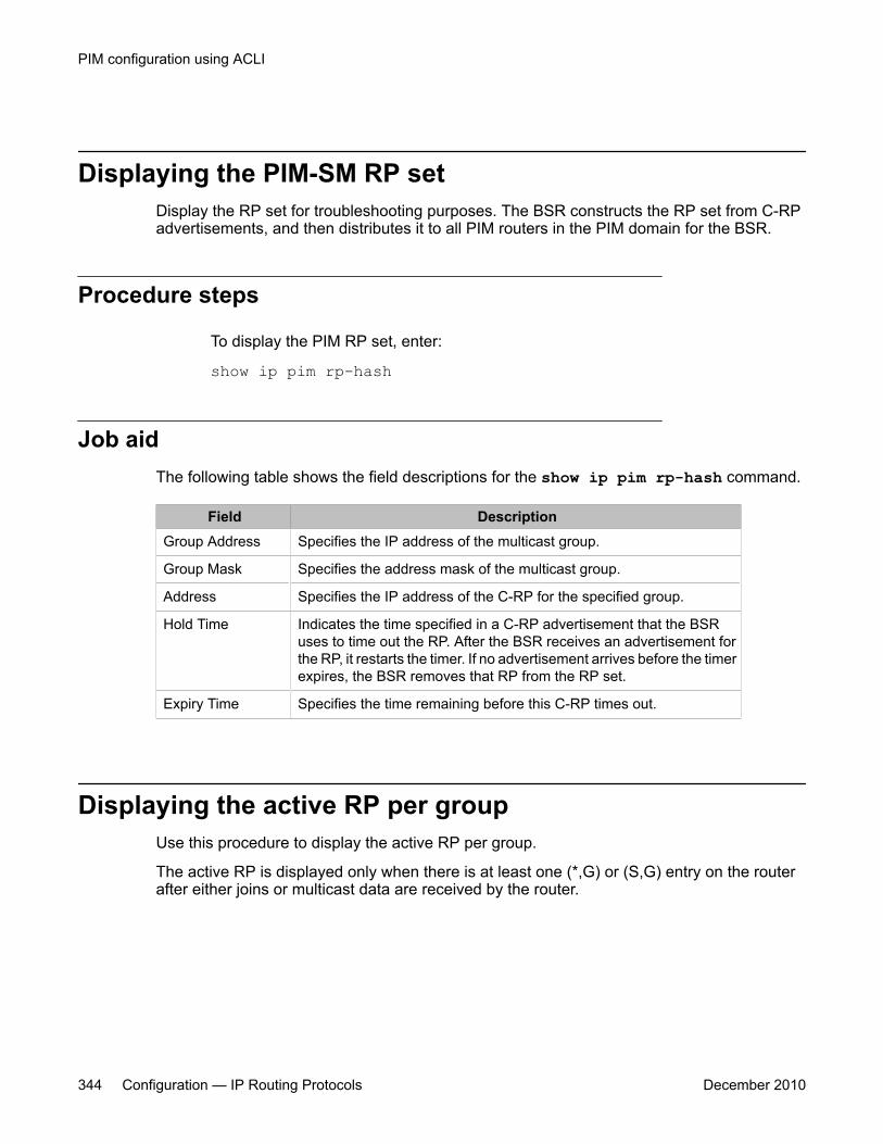
Displaying the PIM-SM RP setDisplay the RP set for troubleshooting purposes. The BSR constructs the RP set from C-RPadvertisements, and then distributes it to all PIM routers in the PIM domain for the BSR.
Procedure steps
To display the PIM RP set, enter:
show ip pim rp-hash
Job aidThe following table shows the field descriptions for the show ip pim rp-hash command.
Field DescriptionGroup Address Specifies the IP address of the multicast group.
Group Mask Specifies the address mask of the multicast group.
Address Specifies the IP address of the C-RP for the specified group.
Hold Time Indicates the time specified in a C-RP advertisement that the BSRuses to time out the RP. After the BSR receives an advertisement forthe RP, it restarts the timer. If no advertisement arrives before the timerexpires, the BSR removes that RP from the RP set.
Expiry Time Specifies the time remaining before this C-RP times out.
Displaying the active RP per groupUse this procedure to display the active RP per group.
The active RP is displayed only when there is at least one (*,G) or (S,G) entry on the routerafter either joins or multicast data are received by the router.
PIM configuration using ACLI
344 Configuration — IP Routing Protocols December 2010
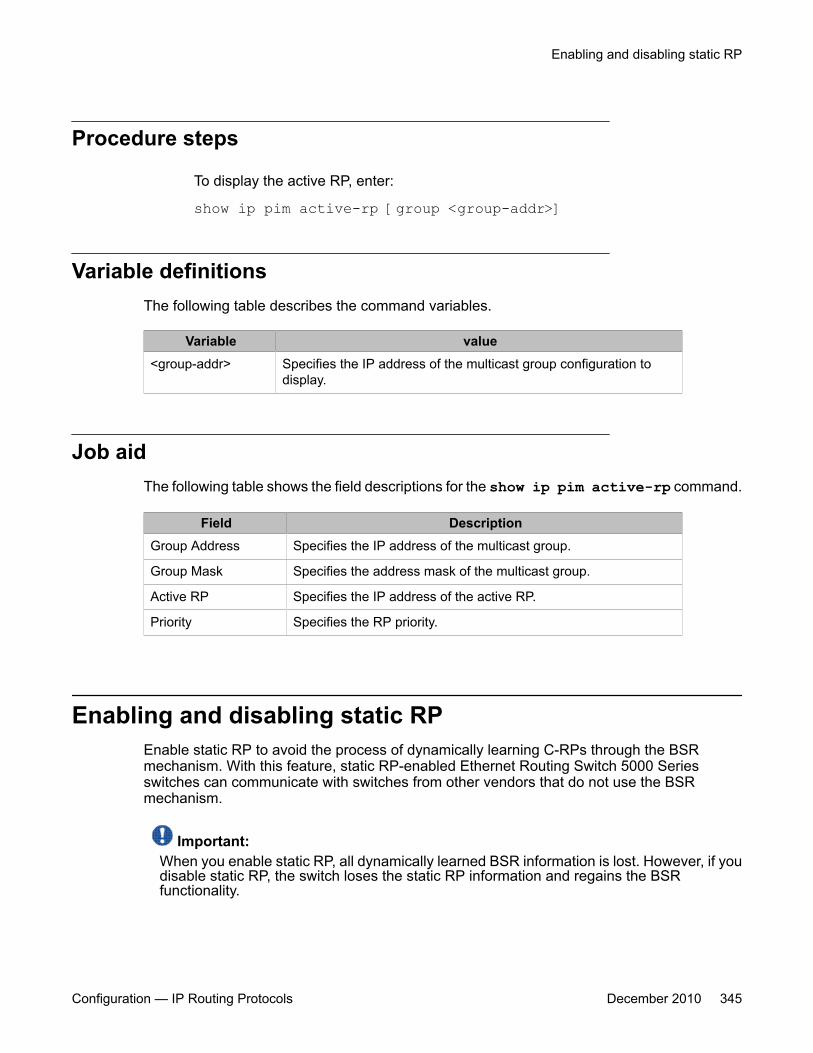
Procedure steps
To display the active RP, enter:
show ip pim active-rp [group <group-addr>]
Variable definitionsThe following table describes the command variables.
Variable value<group-addr> Specifies the IP address of the multicast group configuration to
display.
Job aidThe following table shows the field descriptions for the show ip pim active-rp command.
Field DescriptionGroup Address Specifies the IP address of the multicast group.
Group Mask Specifies the address mask of the multicast group.
Active RP Specifies the IP address of the active RP.
Priority Specifies the RP priority.
Enabling and disabling static RPEnable static RP to avoid the process of dynamically learning C-RPs through the BSRmechanism. With this feature, static RP-enabled Ethernet Routing Switch 5000 Seriesswitches can communicate with switches from other vendors that do not use the BSRmechanism.
Important:When you enable static RP, all dynamically learned BSR information is lost. However, if youdisable static RP, the switch loses the static RP information and regains the BSRfunctionality.
Enabling and disabling static RP
Configuration — IP Routing Protocols December 2010 345
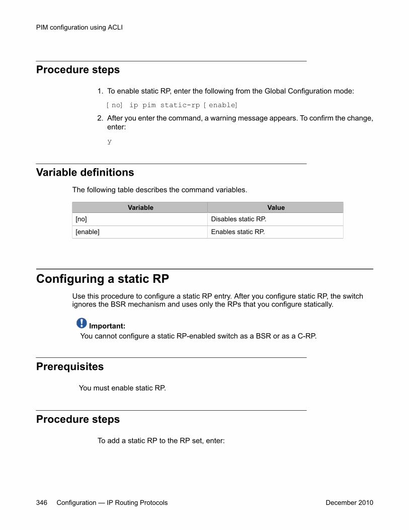
Procedure steps
1. To enable static RP, enter the following from the Global Configuration mode:
[no] ip pim static-rp [enable]2. After you enter the command, a warning message appears. To confirm the change,
enter:
y
Variable definitionsThe following table describes the command variables.
Variable Value[no] Disables static RP.
[enable] Enables static RP.
Configuring a static RPUse this procedure to configure a static RP entry. After you configure static RP, the switchignores the BSR mechanism and uses only the RPs that you configure statically.
Important:You cannot configure a static RP-enabled switch as a BSR or as a C-RP.
Prerequisites
You must enable static RP.
Procedure steps
To add a static RP to the RP set, enter:
PIM configuration using ACLI
346 Configuration — IP Routing Protocols December 2010
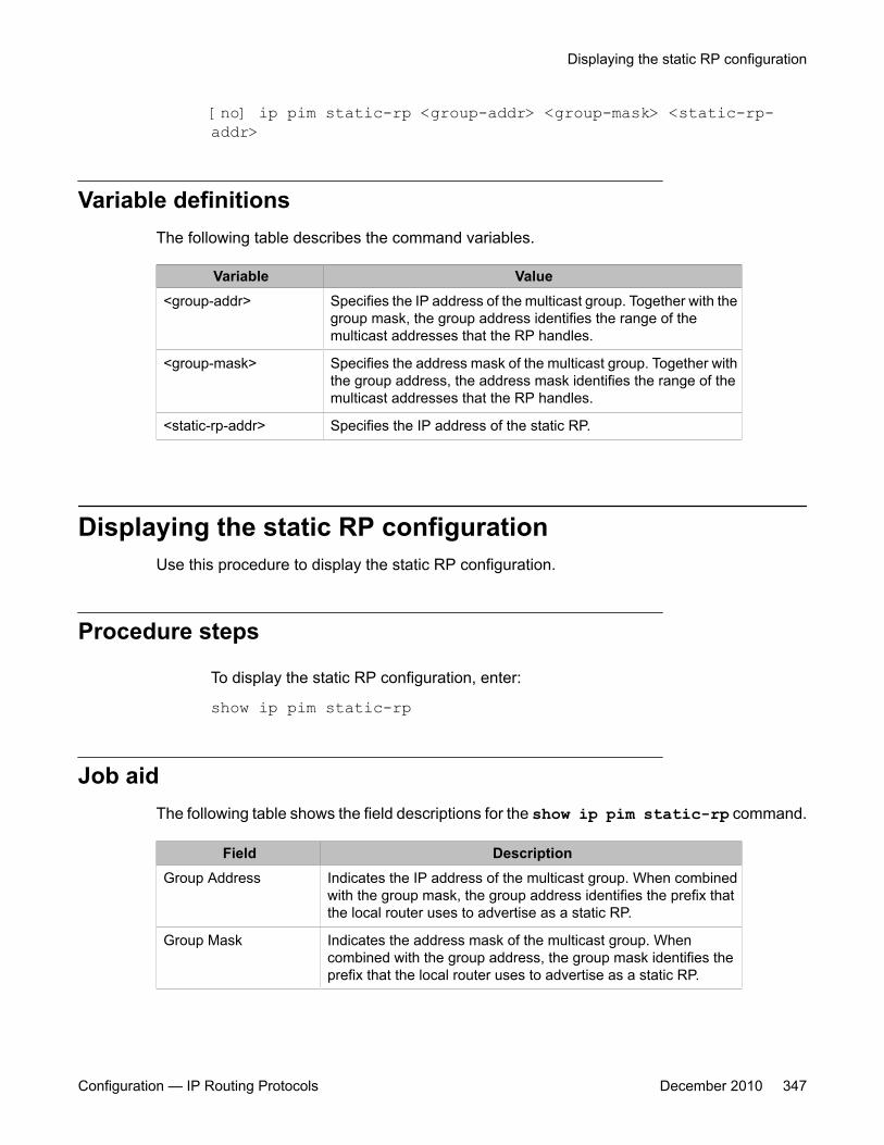
[no] ip pim static-rp <group-addr> <group-mask> <static-rp-addr>
Variable definitionsThe following table describes the command variables.
Variable Value<group-addr> Specifies the IP address of the multicast group. Together with the
group mask, the group address identifies the range of themulticast addresses that the RP handles.
<group-mask> Specifies the address mask of the multicast group. Together withthe group address, the address mask identifies the range of themulticast addresses that the RP handles.
<static-rp-addr> Specifies the IP address of the static RP.
Displaying the static RP configurationUse this procedure to display the static RP configuration.
Procedure steps
To display the static RP configuration, enter:
show ip pim static-rp
Job aidThe following table shows the field descriptions for the show ip pim static-rp command.
Field DescriptionGroup Address Indicates the IP address of the multicast group. When combined
with the group mask, the group address identifies the prefix thatthe local router uses to advertise as a static RP.
Group Mask Indicates the address mask of the multicast group. Whencombined with the group address, the group mask identifies theprefix that the local router uses to advertise as a static RP.
Displaying the static RP configuration
Configuration — IP Routing Protocols December 2010 347

Field DescriptionRP Address Indicates the IP address of the static RP.
Status Indicates the status of static RP.
Specifying a virtual neighbor on an interfaceConfigure a virtual neighbor when the next hop for a static route cannot run PIM-SM, such as aVirtual Redundancy Router Protocol address on an adjacent device. The virtual neighbor IPaddress appears in the Ethernet Routing Switch 5000 neighbor table.
Procedure steps
To configure a virtual neighbor, enter the following from the Global Configuration mode:
[no] ip pim virtual-neighbor <if-ipaddr> <v-nbr-ipaddr>
Variable definitionsThe following table describes the command variables.
Variable Value<if-ipaddr> Specifies the IP address of the selected interface.
<v-nbr-ipaddr> Specifies the IP address of the virtual neighbor.
[no] Removes the configured virtual neighbor.
Displaying the virtual neighbor configurationUse this procedure to display the virtual neighbor.
Procedure steps
To display the virtual neighbor, enter:
PIM configuration using ACLI
348 Configuration — IP Routing Protocols December 2010

show ip pim virtual-neighbor
Job aidThe following table shows the field descriptions for the show ip pim virtual-neighbor command.
Field DescriptionVlan Indicates the VLAN interface.
Neighbor address Indicates the IP address of the virtualneighbor.
Displaying the PIM modeUse this procedure to display the PIM mode.
Procedure steps
To display the PIM mode, enter:
show ip pim mode
Displaying multicast route informationUse this procedure to display multicast route information.
Procedure steps
To display multicast route information, enter:
Displaying the PIM mode
Configuration — IP Routing Protocols December 2010 349

show ip mroute {interface | next-hop | route}
Variable definitionsThe following table describes the command variables.
Variable Valueinterface Displays multicast route information per
interface.
next-hop Displays next-hop information for themulticast routes
route Displays multicast route information.
Job aidsThe following table shows the field descriptions for the show ip mroute interfacecommand.
Field DescriptionInterface Indicates the interface.
Ttl Indicates the datagram TTL threshold for the interface. IP multicastdatagrams with a TTL less than this threshold are not forwarded out of theinterface. The default value of 0 means all multicast packets are forwardedout of the interface.
Protocol Indicates the routing protocol running on this interface.
The following table shows the field descriptions for the show ip mroute next-hopcommand command.
Field DescriptionInterface Indicates the interface identity.
Group Indicates the IP multicast group for which this entry specifies a next hopon an outgoing interface.
Source Indicates the network address, which when combined with thecorresponding value of Scmask identifies the sources for which this entryspecifies a next hop on an outgoing interface.
Srcmask Indicates the network mask, which when combined with the correspondingvalue of Source identifies the sources for which this entry specifies a nexthop on an outgoing interface.
PIM configuration using ACLI
350 Configuration — IP Routing Protocols December 2010
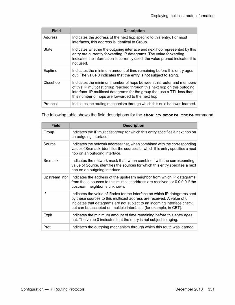
Field DescriptionAddress Indicates the address of the next hop specific to this entry. For most
interfaces, this address is identical to Group.
State Indicates whether the outgoing interface and next hop represented by thisentry are currently forwarding IP datagrams. The value forwardingindicates the information is currently used; the value pruned indicates it isnot used.
Exptime Indicates the minimum amount of time remaining before this entry agesout. The value 0 indicates that the entry is not subject to aging.
Closehop Indicates the minimum number of hops between this router and membersof this IP multicast group reached through this next hop on this outgoinginterface. IP multicast datagrams for the group that use a TTL less thanthis number of hops are forwarded to the next hop
Protocol Indicates the routing mechanism through which this next hop was learned.
The following table shows the field descriptions for the show ip mroute route command.
Field DescriptionGroup Indicates the IP multicast group for which this entry specifies a next hop on
an outgoing interface.
Source Indicates the network address that, when combined with the correspondingvalue of Srcmask, identifies the sources for which this entry specifies a nexthop on an outgoing interface.
Srcmask Indicates the network mask that, when combined with the correspondingvalue of Source, identifies the sources for which this entry specifies a nexthop on an outgoing interface.
Upstream_nbr Indicates the address of the upstream neighbor from which IP datagramsfrom these sources to this multicast address are received, or 0.0.0.0 if theupstream neighbor is unknown.
If Indicates the value of ifIndex for the interface on which IP datagrams sentby these sources to this multicast address are received. A value of 0indicates that datagrams are not subject to an incoming interface check,but can be accepted on multiple interfaces (for example, in CBT).
Expir Indicates the minimum amount of time remaining before this entry agesout. The value 0 indicates that the entry is not subject to aging.
Prot Indicates the outgoing mechanism through which this route was learned.
Displaying multicast route information
Configuration — IP Routing Protocols December 2010 351

PIM configuration using ACLI
352 Configuration — IP Routing Protocols December 2010
Chapter 24: PIM-SM configuration exampleusing ACLI
In this example, A1 is an 8-unit mixed stack of ERS 5500 and ERS 5600 Series switches running IGMPv2snooping.
A2, A3, and CW1 are all ERS 5600 Series switches with PIM-SM enabled.
RIP is used as the Layer 3 routing protocol but you can also configure OSPF or static routes accordingto your network requirements. The PIM, MLT, VRRP, and IGMP settings provided remain unaffected bythe choice of routing protocol.
The multicast group range is 224.10.10.0 255.255.255.0.
The STG, MLT, and VLAN number information are displayed in the following figure which shows a sampletopology using PIM-SM.
Configuration — IP Routing Protocols December 2010 353

Figure 49: PIM-SM sample topology
PIM-SM configuration example using ACLI
354 Configuration — IP Routing Protocols December 2010
A1 descriptionA1 is an 8-unit mixed stack of 5500 and 5600 Series switches running IGMPv2 snooping. Thereare a total of two multicast clients on the access layer connected to the A1 stack, each in adifferent VLAN (2101 and 2102) and in a different network.
For simplicity, the configuration shows only two clients connected to the access layer stack.You can add more ports to each VLAN on the stack to have more users per VLAN.
A2 and A3 descriptionThe distribution layer switches (A2 and A3) are configured as dynamic C-RPs or static RPs(configurations for both options are provided). You can use static RP or dynamic RP (but notboth) in accordance with the requirements of your network. If you choose static RP, you mustconfigure the same static RP on every PIM router in your network.
VRRP is enabled on A2 and A3, and all multicast clients have the VRRP virtual IP address asthe default gateway for a specific VLAN.
Important:The VRRP configuration shown is an optional configuration providing a virtual IP for the hostgateway. If your network does not need a virtual IP for a gateway, you do not need toconfigure VRRP. PIM-SM is independent of VRRP.
In this example, A3 is the DR for both PIM client VLANs (2101 and 2102), so all (S,G) entriesinstall on A3. However, you can manage the DR election for the client VLANs by manipulatingthe IP address of the A2 and A3 VLAN interfaces. To load-share between A2 and A3, you canconfigure one of the VLAN interfaces on A2 (for example, 2101) with a higher IP address thanthe corresponding VLAN interface on A3. For the second VLAN, 2102, you can maintain thehigher IP address on the A3 interface. In this way, A2 can become the DR for VLAN 2101, andA3 can remain the DR for VLAN 2102. This allows the (S,G) load to be split between the twoswitches and the system to be used to its maximum limits.
CW1 descriptionCW1 is configured as the BSR with priority 10 (only applicable to dynamic RP). A higher priorityindicates a higher probability of being elected the BSR.
A1 description
Configuration — IP Routing Protocols December 2010 355
CW1 is directly connected to the multicast server. If desired, you can have a Layer 2 switchbetween the CW1 and the server with VLAN 3000 spanning through the switch to maintain theconnection.
The CW1 connection to the multicast server is configured as a passive interface as it is on theedge and is not required to form a neighbor relationship with any other PIM router. You canconfigure this interface as an active interface according to the requirements of your network.
Link descriptionsThe link connections (port numbers) between devices are listed below; the physicalconnections are in a one-to-one mapping in sequence as listed for each set of connections.
• A2 – A1:
- 12,24,36,48,60,72,86,90 – 1/2,2/14,3/14,4/38,5/12,6/14,7/2,8/2
- MLT 7, VLAN 2101 to 2128, STG 8
• A3 – A1:
- 2,14,26,38,50,62,74,80 -- 1/48,2/48,3/2,4/2,5/14,6/38,7/14,8/14
- MLT 8, VLAN 2101 to 2128, STG 8
• A2 – A3:
- 95,96 – 95,96
- MLT 2, VLAN 2, STG 2
• A2 – CW1:
- 91,92 –23,24
- MLT 5, VLAN 5, STG 5
• A3 – CW1:
- 91,92 – 21,22
- MLT 7, VLAN 7, STG 7
• CW1 – Multicast server NIC:
12 – Multicast server NIC
• A1 – Multicast client NICs:
- VLAN 2101: 1/11 – MC1
- VLAN 2102: 2/11 – MC2
PIM-SM configuration example using ACLI
356 Configuration — IP Routing Protocols December 2010

See the following sections to configure the topology shown. In addition to the listedconfigurations, you can also configure the optional PIM-SM global and interface parameters,although it is advisable to leave these parameters at their default values.
A1 configurationThe following procedure shows the configuration required for the A1 mixed stack running IGMPsnooping.
1. Enter Global Configuration mode:
configure terminal2. Enable tagging on ports:
vlan port 1/2,2/14,3/14,4/38,5/12,6/14,7/2,8/2,1/48,2/48,3/2,4/2,5/14,6/38,7/14,8/14 tagging enable
3. Create the spanning tree instance:
spanning-tree stp 8 create4. Configure the VLANs:
vlan members remove 11/2,2/14,3/14,4/38,5/12,6/14,7/2,8/2,1/48,2/48,3/2,4/2,5/14,6/38,7/14,8/14
vlan create 2101 type portvlan members add 2101 1/2,2/14,3/14,4/38,5/12,6/14,7/2,8/2,1/48,2/48,3/2,4/2,5/14,6/38,7/14,8/14,1/11spanning-tree stp 8add-vlan 2101int vlan 2101 ip igmp snoopingip igmp mrouter 1/2,2/14,3/14,4/38,5/12,6/14,7/2,8/2,1/48,2/48,3/2,4/2, 5/14,6/38,7/14,8/14
vlan create 2102 type portvlan members add 2102 1/2,2/14,3/14,4/38,5/12,6/14,7/2,8/2,1/48,2/48,3/2,4/2,5/14,6/38,7/14,8/14,2/11spanning-tree stp 8 add-vlan 2102int vlan 2102ip igmp snooping ip igmp mrouter 1/2,2/14,3/14,4/38,5/12,6/14,7/2,8/2,1/48,2/48,3/2,4/2, 5/14,6/38,7/14,8/14
5. Enable spanning tree:
A1 configuration
Configuration — IP Routing Protocols December 2010 357
spanning-tree 8 enable6. Configure the MLTs:
mlt 7 member 1/2,2/14,3/14,4/38,5/12,6/14,7/2,8/2 mlt 7 enable mlt 8 member 1/48,2/48,3/2,4/2,5/14,6/38,7/14,8/14 mlt 8 enable
A2 configurationThe following procedure shows the configuration required for the A2 PIM-SM-enableddistribution layer 5600 Series switch running VRRP and RIP.
1. Enter Global Configuration mode:
configure terminal2. Enable RIP and PIM:
ip routing router rip enable ip pim enable3. Enable tagging on ports:
vlan port 95-96,98,91-92,12,24,36,48,60,72,86,90 taggingenable
4. Configure the VLANs:
vlan members remove 1 12,24,36,48,60,72,86,90,95,96,91,92 vlan create 2 type portvlan members remove 1 95-96vlan members add 2 95-96interface vlan 2ip address 190.1.1.2 255.255.255.0ip pim enip rip en
vlan create 5 type portvlan members remove 1 91-92vlan members add 5 91-92interface vlan 5ip address 150.16.107.2 255.255.255.0ip pim enip rip en vlan create 2101 type portvlan members add 2101 12,24,36,48,60,72,86,90interface vlan 2101ip address 170.1.1.1 255.255.255.0ip pim enip rip en
PIM-SM configuration example using ACLI
358 Configuration — IP Routing Protocols December 2010
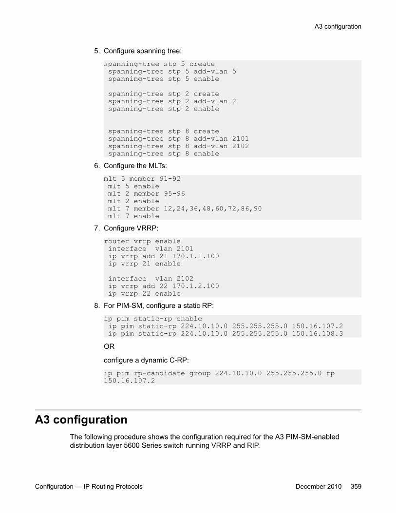
5. Configure spanning tree:
spanning-tree stp 5 create spanning-tree stp 5 add-vlan 5 spanning-tree stp 5 enable
spanning-tree stp 2 create spanning-tree stp 2 add-vlan 2 spanning-tree stp 2 enable
spanning-tree stp 8 create spanning-tree stp 8 add-vlan 2101 spanning-tree stp 8 add-vlan 2102 spanning-tree stp 8 enable
6. Configure the MLTs:
mlt 5 member 91-92 mlt 5 enable mlt 2 member 95-96 mlt 2 enable mlt 7 member 12,24,36,48,60,72,86,90 mlt 7 enable
7. Configure VRRP:
router vrrp enable interface vlan 2101 ip vrrp add 21 170.1.1.100 ip vrrp 21 enable
interface vlan 2102 ip vrrp add 22 170.1.2.100 ip vrrp 22 enable
8. For PIM-SM, configure a static RP:
ip pim static-rp enable ip pim static-rp 224.10.10.0 255.255.255.0 150.16.107.2 ip pim static-rp 224.10.10.0 255.255.255.0 150.16.108.3OR
configure a dynamic C-RP:
ip pim rp-candidate group 224.10.10.0 255.255.255.0 rp 150.16.107.2
A3 configurationThe following procedure shows the configuration required for the A3 PIM-SM-enableddistribution layer 5600 Series switch running VRRP and RIP.
A3 configuration
Configuration — IP Routing Protocols December 2010 359

1. Enter Global Configuration mode:
configure terminal2. Enable RIP and PIM:
ip routingrouter rip enableip pim enable
3. Enable tagging on ports:vlan port 95-96,98,91-92,2,14,26,38,50,62,74,80tagging ena
4. Configure the VLANs:vlan members remove 1 2,14,26,38,50,62,74,80
vlan create 2 type portvlan members remove 1 95-96vlan members add 2 95-96interface vlan 2ip address 190.1.1.3 255.255.255.0ip pim enip rip en
vlan create 7 type portvlan members remove 1 91-92vlan members add 7 91-92 interface vlan 7ip address 150.16.108.3 255.255.255.0ip pim enip rip en
vlan create 2101 type port vlan members add 2101 2,14,26,38,50,62,74,80interface vlan 2101ip address 170.1.1.2 255.255.255.0ip pim enip rip en
vlan create 2102 type portvlan members add 2102 2,14,26,38,50,62,74,80,49interface vlan 2102ip address 170.1.2.2 255.255.255.0ip pim enip rip en
5. Configure spanning tree:spanning-tree stp 7 createspanning-tree stp 7 add-vlan 7spanning-tree stp 7 enablespanning-tree stp 2 createspanning-tree stp 2 add-vlan 2spanning-tree stp 2 enablespanning-tree stp 8 createspanning-tree stp 8 add-vlan 2101spanning-tree stp 8 add-vlan 2102spanning-tree stp 8 enable
6. Configure the MLTs:mlt 7 member 91-92mlt 7 enable
PIM-SM configuration example using ACLI
360 Configuration — IP Routing Protocols December 2010

mlt 2 member 95-96mlt 2 enable
mlt 8 member 2,14,26,38,50,62,74,80mlt 8 enable
7. Configure VRRP:router vrrp enableinterface vlan 2101ip vrrp add 21 170.1.1.100ip vrrp 21 enab
interface vlan 2102ip vrrp add 22 170.1.2.100ip vrrp 22 enab
8. For PIM-SM, configure a static RP:ip pim static-rp enableip pim static-rp 224.10.10.0 255.255.255.0 150.16.107.2ip pim static-rp 224.10.10.0 255.255.255.0 150.16.108.3
OR
configure a dynamic C-RP:ip pim rp-candidate group 224.10.10.0 255.255.255.0 rp 150.16.108.3
CW1The following procedure shows the configuration required for the CW1 PIM-SM-enabled 5600Series switch running RIP. This is the source DR.
The following procedure shows the configuration required for the CW1 PIM-SM-enabled switchrunning RIP.
1. Enter Global Configuration mode:
configure terminal2. Enable RIP and PIM:
ip routingrouter rip enableip pim enable
3. Enable tagging on ports:vlan port 1-2,13-14,21-24,25,29,32 tagging ena
4. Configure the VLAN:vlan mem remove 1 23,24,21,22,12
vlan create 5 type portvlan members add 5 23-24interface vlan 5ip address 150.16.107.1 255.255.255.0
CW1
Configuration — IP Routing Protocols December 2010 361
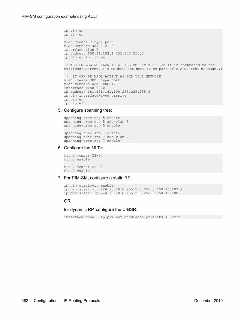
ip pim enip rip en
vlan create 7 type portvlan members add 7 21-22interface vlan 7ip address 150.16.108.1 255.255.255.0ip pim en ip rip en
!! THE FOLLOWING VLAN IS A PASSIVE PIM VLAN (As it is connected to the multicast server, and it does not need to be part of PIM control messages.)
!! IT CAN BE MADE ACTIVE AS PER YOUR NETWORKvlan create 3000 type portvlan members add 3000 12interface vlan 3000ip address 181.181.181.100 255.255.255.0ip pim interface-type passiveip pim enip rip en
5. Configure spanning tree:spanning-tree stp 5 createspanning-tree stp 5 add-vlan 5spanning-tree stp 5 enable
spanning-tree stp 7 createspanning-tree stp 7 add-vlan 7spanning-tree stp 7 enable
6. Configure the MLTs:mlt 5 member 23-24mlt 5 enable
mlt 7 member 21-22mlt 7 enable
7. For PIM-SM, configure a static RP:ip pim static-rp enableip pim static-rp 224.10.10.0 255.255.255.0 150.16.107.2ip pim static-rp 224.10.10.0 255.255.255.0 150.16.108.3
OR
for dynamic RP, configure the C-BSR:interface vlan 5 ip pim bsr-candidate priority 10 exit
PIM-SM configuration example using ACLI
362 Configuration — IP Routing Protocols December 2010
Chapter 25: Basic IPv6 routing configurationusing ACLI
This chapter describes how to use the ACLI to configure basic IPv6 routing.
Basic IPv6 routing configuration proceduresTo configure basic IPv6 routing, perform the following steps:
1. Enable global IPv6 routing on the switch.
2. Configure a minimum of one link-local, site-local, or global IPv6 address for eachIPv6 VLAN.
3. Configure neighbor discovery prefixes, if desired.
4. Configure static routes, if desired.
5. Configure router advertisement and ICMP properties, as well as the neighbor cache,if desired.
Navigation
• Configuring global IPv6 routing status on page 364
• Displaying global IPv6 configuration on page 364
• Configuring an IPv6 address for a VLAN on page 365
• Removing the IPv6 address configuration from a VLAN on page 366
• Displaying IPv6 address configuration for a VLAN on page 367
• Configuring neighbor discovery prefixes on page 367
• Displaying neighbor discovery prefix configuration on page 369
• Configuring router advertisement on page 369
• Configuring IPv6 ICMP on page 371
• Configuring IPv6 static routes on page 372
• Displaying IPv6 static routes on page 373
Configuration — IP Routing Protocols December 2010 363
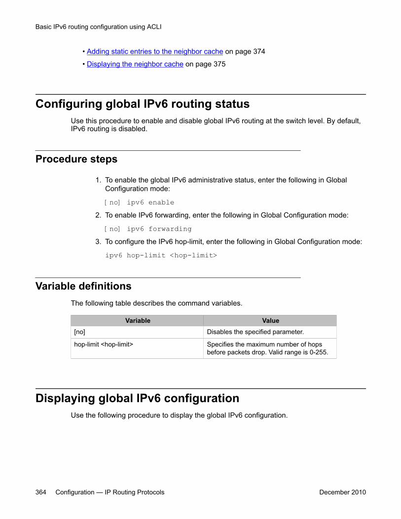
• Adding static entries to the neighbor cache on page 374
• Displaying the neighbor cache on page 375
Configuring global IPv6 routing statusUse this procedure to enable and disable global IPv6 routing at the switch level. By default,IPv6 routing is disabled.
Procedure steps
1. To enable the global IPv6 administrative status, enter the following in GlobalConfiguration mode:
[no] ipv6 enable2. To enable IPv6 forwarding, enter the following in Global Configuration mode:
[no] ipv6 forwarding3. To configure the IPv6 hop-limit, enter the following in Global Configuration mode:
ipv6 hop-limit <hop-limit>
Variable definitionsThe following table describes the command variables.
Variable Value[no] Disables the specified parameter.
hop-limit <hop-limit> Specifies the maximum number of hopsbefore packets drop. Valid range is 0-255.
Displaying global IPv6 configurationUse the following procedure to display the global IPv6 configuration.
Basic IPv6 routing configuration using ACLI
364 Configuration — IP Routing Protocols December 2010
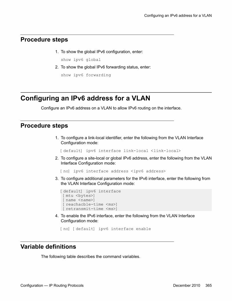
Procedure steps
1. To show the global IPv6 configuration, enter:
show ipv6 global2. To show the global IPv6 forwarding status, enter:
show ipv6 forwarding
Configuring an IPv6 address for a VLANConfigure an IPv6 address on a VLAN to allow IPv6 routing on the interface.
Procedure steps
1. To configure a link-local identifier, enter the following from the VLAN InterfaceConfiguration mode:
[default] ipv6 interface link-local <link-local>2. To configure a site-local or global IPv6 address, enter the following from the VLAN
Interface Configuration mode:
[no] ipv6 interface address <ipv6 address>3. To configure additional parameters for the IPv6 interface, enter the following from
the VLAN Interface Configuration mode:
[default] ipv6 interface [mtu <bytes>] [name <name>] [reachacble-time <ms>] [retransmit-time <ms>]
4. To enable the IPv6 interface, enter the following from the VLAN InterfaceConfiguration mode:
[no] [default] ipv6 interface enable
Variable definitionsThe following table describes the command variables.
Configuring an IPv6 address for a VLAN
Configuration — IP Routing Protocols December 2010 365

Variable Value[no] Removes the specified configuration or parameter.
default Configures the specified parameter to the default value.
address <ipv6 address> Configures the IPv6 address and prefix length. The defaultvalue is none.
link-local <link-local> Configures the link local identifier. The default value is none.
mtu <bytes> Configures the maximum transmission unit for the interface.The default value is 1500.
name <name> Configures a description for the interface. This variable doesnot support the default parameter.
reachable-time <ms> Configures the time, in milliseconds, that a neighbor isconsidered reachable after receiving a reachabilityconfirmation. Range is 0-3600000. The default value is 30000.
retransmit-time <ms> Configures the time, in milliseconds, between retransmissionsof Neighbor Solicitation messages to a neighbor whenresolving the address or when probing the reachability of aneighbor. Range is 0-3600000. The default value is 1000.
Removing the IPv6 address configuration from a VLANUse the following procedure to disable the IPv6 interface status and delete the IPv6 addressfrom a VLAN.
Procedure steps
To disable the IPv6 interface status and delete the IPv6 address, enter the followingfrom the VLAN Interface Configuration mode:
{no | default} ipv6 interface all
Variable definitionsThe following table describes the command variables.
Variable Valueno Disables the IPv6 interface status and
deletes the IPv6 address.
Basic IPv6 routing configuration using ACLI
366 Configuration — IP Routing Protocols December 2010
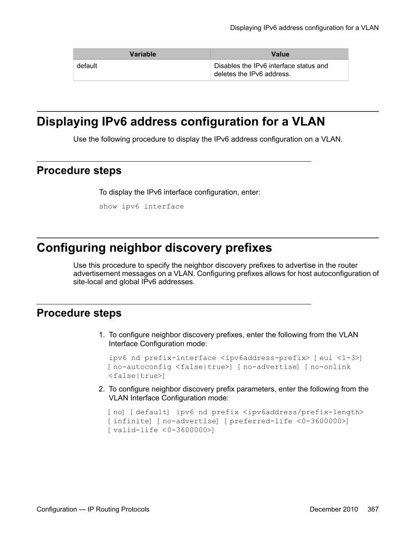
Variable Valuedefault Disables the IPv6 interface status and
deletes the IPv6 address.
Displaying IPv6 address configuration for a VLANUse the following procedure to display the IPv6 address configuration on a VLAN.
Procedure steps
To display the IPv6 interface configuration, enter:
show ipv6 interface
Configuring neighbor discovery prefixesUse this procedure to specify the neighbor discovery prefixes to advertise in the routeradvertisement messages on a VLAN. Configuring prefixes allows for host autoconfiguration ofsite-local and global IPv6 addresses.
Procedure steps
1. To configure neighbor discovery prefixes, enter the following from the VLANInterface Configuration mode:
ipv6 nd prefix-interface <ipv6address-prefix> [eui <1-3>][no-autoconfig <false|true>] [no-advertise] [no-onlink<false|true>]
2. To configure neighbor discovery prefix parameters, enter the following from theVLAN Interface Configuration mode:
[no] [default] ipv6 nd prefix <ipv6address/prefix-length>[infinite] [no-advertise] [preferred-life <0-3600000>][valid-life <0-3600000>]
Displaying IPv6 address configuration for a VLAN
Configuration — IP Routing Protocols December 2010 367

Variable definitionsThe following table describes the command variables.
Variable Value[no] Deletes the specified configuration.
[default] Sets the specified parameter to the defaultvalue.
eui <1-3> Specifies the EUI parameter setting:
1. Extended Unique Identifier (EUI) is notused
2. EUI with U/L (Universal/Local bit)complement is enabled
3. EUI is used without U/L
The default value is 1 - EUI is not used.
no-advertise Specifies whether the prefix is advertised. Ifconfigured, this parameter prevents prefixadvertisement. The default value is false.
no-autoconfig <false|true> If true, the prefix is used for autonomousaddress configuration. The default value istrue.
no-onlink <false|true> If true, onlink determination uses the prefix.This value is placed in the L-bit field in theprefix information option. It is a 1-bit flag. Thedefault value is true.
infinite If configured, the prefix does not expire. Thedefault value is false.
preferred-life <0-3600000> The number of seconds that the prefix canaccept and use new connections. Thedefault value is 604800.
valid-life <0-3600000> The number of seconds that the prefixadvertised in the neighbor advertisement isvalid. During the valid lifetime, existingconnections can be used. New connectionscannot be opened. The default value is2592000.
Basic IPv6 routing configuration using ACLI
368 Configuration — IP Routing Protocols December 2010
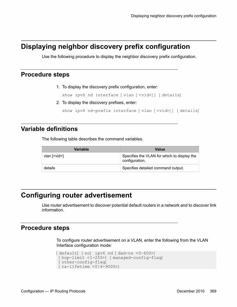
Displaying neighbor discovery prefix configurationUse the following procedure to display the neighbor discovery prefix configuration.
Procedure steps
1. To display the discovery prefix configuration, enter:
show ipv6 nd interface [vlan [<vid>]] [details]2. To display the discovery prefixes, enter:
show ipv6 nd-prefix interface [vlan [<vid>]] [details]
Variable definitionsThe following table describes the command variables.
Variable Valuevlan [<vid>] Specifies the VLAN for which to display the
configuration.
details Specifies detailed command output.
Configuring router advertisementUse router advertisement to discover potential default routers in a network and to discover linkinformation.
Procedure steps
To configure router advertisement on a VLAN, enter the following from the VLANInterface configuration mode:
[default] [no] ipv6 nd [dad-ns <0-600>] [hop-limit <1-255>] [managed-config-flag] [other-config-flag] [ra-lifetime <0|4-9000>]
Displaying neighbor discovery prefix configuration
Configuration — IP Routing Protocols December 2010 369

[rtr-advert-max-interval <4-1800>] [rtr-advert-min-interval <3-1350>] [send-ra]
Variable definitionsThe following table describes the command variables.
Variable Value[default] Configures the specified parameter to the
default value.
[no] Deletes or disables the specified parameter.
dad-ns The number of neighbor solicitationmessages from duplicate address detection.The acceptable range is 0-600. A value of 0disables duplicate address detection on thespecified interface. A value of 1 configures asingle transmission without follow-uptransmissions. Use the default operator toconfigure this value to the default setting.The default value is 1.
hop-limit Enter the maximum number of hops beforepackets drop. Use the default operator toconfigure this value to the default setting.The default value is 30.
managed-config-flag Configure to true to enable M-bit (managedaddress configuration) on the router. Use theno operator to remove this option. Use thedefault operator to configure this value to thedefault setting. The default value is false.
other-config-flag Configure to true to enable the O-bit (otherstateful configuration) in the routeradvertisement. Other stateful configurationautoconfigures received information withoutaddresses. Use the no operator to removethis option. Use the default operator toconfigure this value to the default setting.The default value is false.
ra-lifetime Enter the router lifetime included in routeradvertisement. Other devices use thisinformation to determine if the router can bereached. The range is 0 or 4–9000. Use thedefault operator to configure this value to thedefault setting. The default value is 1800.
Basic IPv6 routing configuration using ACLI
370 Configuration — IP Routing Protocols December 2010

Variable Valuertr-advert-max-interval Configures the maximum time allowed
between sending unsolicited multicast routeradvertisements. The default value is 600.
rtr-advert-min-interval Configures the minimum time allowed, inseconds (3–1350), between sendingunsolicited multicast router advertisementsfrom the interface. Use the default operatorto configure this value to the default setting.The default value is 200.
send-ra Enables or disables periodic routeradvertisement messages. Use the nooperator to remove this option. Use thedefault operator to configure this value to thedefault setting. The default value is true.
Configuring IPv6 ICMPConfigure Internet Control Message Protocol (ICMP) parameters to modify the transport errorand information messages within IPv6 packets.
Procedure steps
1. To configure the ICMP rate, enter the following from Global Configuration mode:
[no] [default] ipv6 icmp error-interval <0-2147483647>2. To set the status for redirect messages, enter the following from Global
Configuration mode:
[no] [default] ipv6 icmp redirect-msg3. To configure the status for unreachable messages, enter using the following from
Global Configuration mode:
[no] [default] ipv6 icmp unreach-msg
Variable definitionsThe following table describes the command variables.
Configuring IPv6 ICMP
Configuration — IP Routing Protocols December 2010 371
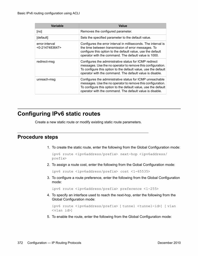
Variable Value[no] Removes the configured parameter.
[default] Sets the specified parameter to the default value.
error-interval<0-2147483647>
Configures the error interval in milliseconds. The interval isthe time between transmission of error messages. Toconfigure this option to the default value, use the defaultoperator with the command. The default value is 1000.
redirect-msg Configures the administrative status for ICMP redirectmessages. Use the no operator to remove this configuration.To configure this option to the default value, use the defaultoperator with the command. The default value is disable.
unreach-msg Configures the administrative status for ICMP unreachablemessages. Use the no operator to remove this configuration.To configure this option to the default value, use the defaultoperator with the command. The default value is disable.
Configuring IPv6 static routesCreate a new static route or modify existing static route parameters.
Procedure steps
1. To create the static route, enter the following from the Global Configuration mode:
ipv6 route <ipv6address/prefix> next-hop <ipv6address/prefix>
2. To assign a route cost, enter the following from the Gobal Configuration mode:
ipv6 route <ipv6address/prefix> cost <1-65535>3. To configure a route preference, enter the following from the Global Configuration
mode:
ipv6 route <ipv6address/prefix> preference <1-255>4. To specify an interface used to reach the next-hop, enter the following from the
Global Configuration mode:
ipv6 route <ipv6address/prefix> [tunnel <tunnel-id>] [vlan<vlan id>]
5. To enable the route, enter the following from the Global Configuration mode:
Basic IPv6 routing configuration using ACLI
372 Configuration — IP Routing Protocols December 2010
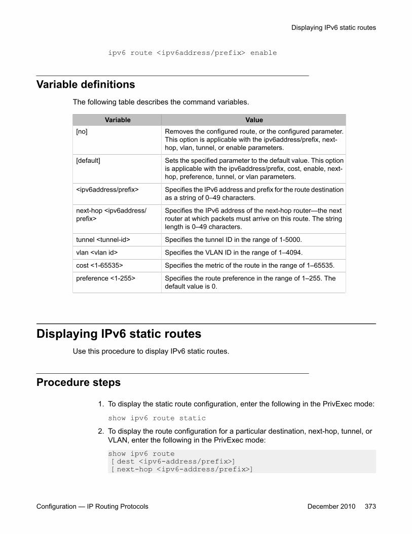
ipv6 route <ipv6address/prefix> enable
Variable definitionsThe following table describes the command variables.
Variable Value[no] Removes the configured route, or the configured parameter.
This option is applicable with the ipv6address/prefix, next-hop, vlan, tunnel, or enable parameters.
[default] Sets the specified parameter to the default value. This optionis applicable with the ipv6address/prefix, cost, enable, next-hop, preference, tunnel, or vlan parameters.
<ipv6address/prefix> Specifies the IPv6 address and prefix for the route destinationas a string of 0–49 characters.
next-hop <ipv6address/prefix>
Specifies the IPv6 address of the next-hop router—the nextrouter at which packets must arrive on this route. The stringlength is 0–49 characters.
tunnel <tunnel-id> Specifies the tunnel ID in the range of 1-5000.
vlan <vlan id> Specifies the VLAN ID in the range of 1–4094.
cost <1-65535> Specifies the metric of the route in the range of 1–65535.
preference <1-255> Specifies the route preference in the range of 1–255. Thedefault value is 0.
Displaying IPv6 static routesUse this procedure to display IPv6 static routes.
Procedure steps
1. To display the static route configuration, enter the following in the PrivExec mode:
show ipv6 route static2. To display the route configuration for a particular destination, next-hop, tunnel, or
VLAN, enter the following in the PrivExec mode:
show ipv6 route [dest <ipv6-address/prefix>] [next-hop <ipv6-address/prefix>]
Displaying IPv6 static routes
Configuration — IP Routing Protocols December 2010 373
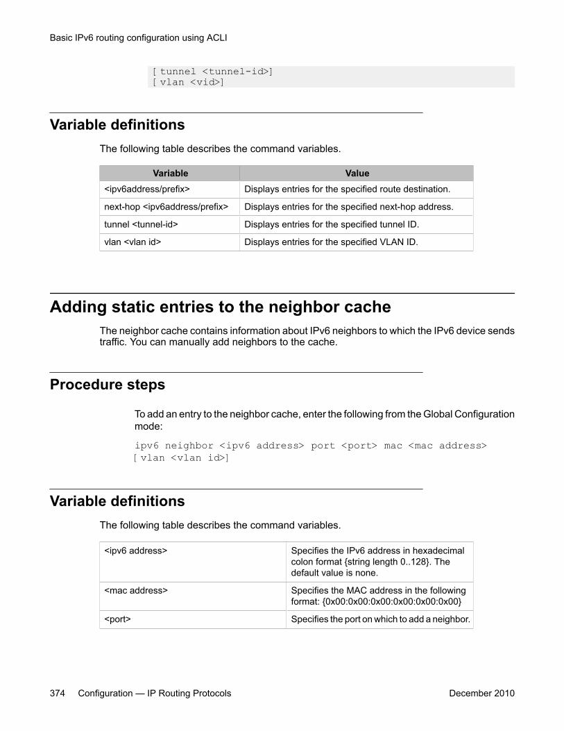
[tunnel <tunnel-id>] [vlan <vid>]
Variable definitionsThe following table describes the command variables.
Variable Value<ipv6address/prefix> Displays entries for the specified route destination.
next-hop <ipv6address/prefix> Displays entries for the specified next-hop address.
tunnel <tunnel-id> Displays entries for the specified tunnel ID.
vlan <vlan id> Displays entries for the specified VLAN ID.
Adding static entries to the neighbor cacheThe neighbor cache contains information about IPv6 neighbors to which the IPv6 device sendstraffic. You can manually add neighbors to the cache.
Procedure steps
To add an entry to the neighbor cache, enter the following from the Global Configurationmode:
ipv6 neighbor <ipv6 address> port <port> mac <mac address>[vlan <vlan id>]
Variable definitionsThe following table describes the command variables.
<ipv6 address> Specifies the IPv6 address in hexadecimalcolon format {string length 0..128}. Thedefault value is none.
<mac address> Specifies the MAC address in the followingformat: {0x00:0x00:0x00:0x00:0x00:0x00}
<port> Specifies the port on which to add a neighbor.
Basic IPv6 routing configuration using ACLI
374 Configuration — IP Routing Protocols December 2010
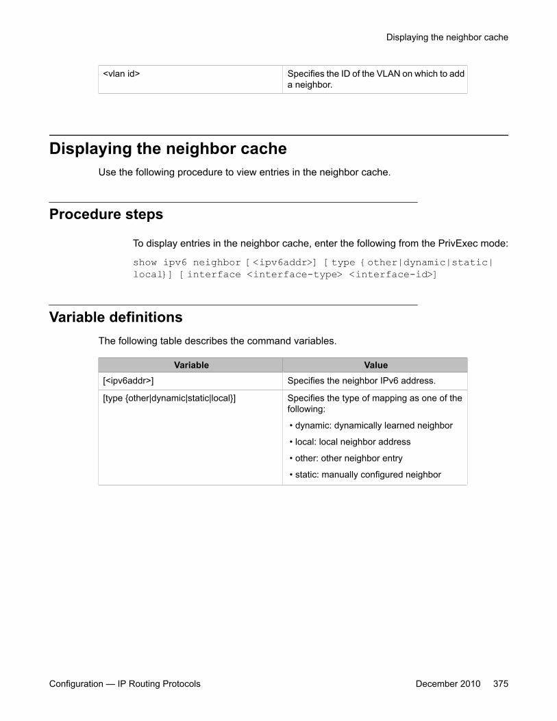
<vlan id> Specifies the ID of the VLAN on which to adda neighbor.
Displaying the neighbor cacheUse the following procedure to view entries in the neighbor cache.
Procedure steps
To display entries in the neighbor cache, enter the following from the PrivExec mode:
show ipv6 neighbor [<ipv6addr>] [type {other|dynamic|static|local}] [interface <interface-type> <interface-id>]
Variable definitionsThe following table describes the command variables.
Variable Value[<ipv6addr>] Specifies the neighbor IPv6 address.
[type {other|dynamic|static|local}] Specifies the type of mapping as one of thefollowing:
• dynamic: dynamically learned neighbor
• local: local neighbor address
• other: other neighbor entry
• static: manually configured neighbor
Displaying the neighbor cache
Configuration — IP Routing Protocols December 2010 375

Basic IPv6 routing configuration using ACLI
376 Configuration — IP Routing Protocols December 2010
Chapter 26: IPv6 DHCP Relay configurationusing ACLI
This chapter describes how to use the ACLI to configure IPv6 DHCP Relay.
IPv6 DHCP Relay configuration proceduresTo configure IPv6 DHCP Relay, perform the following steps:
1. Specify the local relay agent and remote server.
2. Enable IPv6 DHCP Relay on the VLAN.
Navigation• Specifying a local DHCP relay agent and remote DHCP server on page 377
• Displaying the DHCP relay configuration on page 379
• Configuring DHCP relay status and parameters on a VLAN on page 379
• Displaying the DHCP relay configuration for a VLAN on page 380
• Displaying DHCP relay counters on page 381
Specifying a local DHCP relay agent and remote DHCPserver
Use this procedure to specify a VLAN as a DHCP relay agent on the forwarding path to aremote DHCP server. The DHCP relay agent can forward DHCP client requests from the localnetwork to the DHCP server in the remote network.
Configuration — IP Routing Protocols December 2010 377
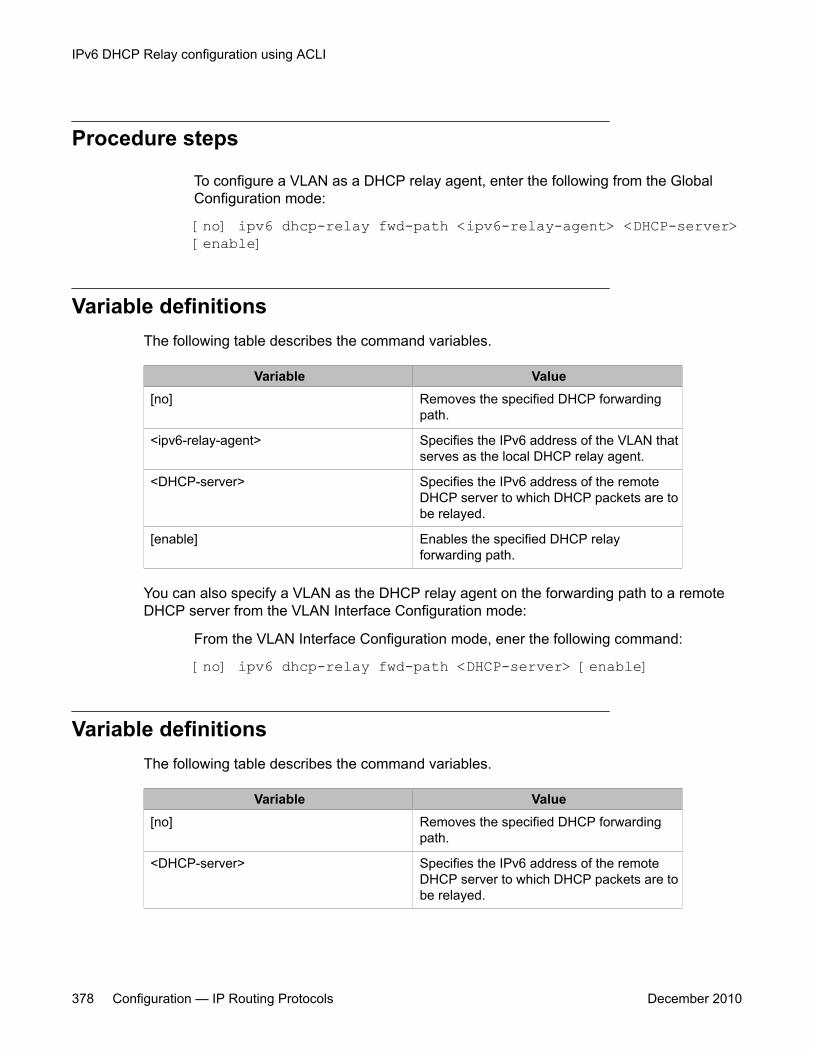
Procedure steps
To configure a VLAN as a DHCP relay agent, enter the following from the GlobalConfiguration mode:
[no] ipv6 dhcp-relay fwd-path <ipv6-relay-agent> <DHCP-server>[enable]
Variable definitionsThe following table describes the command variables.
Variable Value[no] Removes the specified DHCP forwarding
path.
<ipv6-relay-agent> Specifies the IPv6 address of the VLAN thatserves as the local DHCP relay agent.
<DHCP-server> Specifies the IPv6 address of the remoteDHCP server to which DHCP packets are tobe relayed.
[enable] Enables the specified DHCP relayforwarding path.
You can also specify a VLAN as the DHCP relay agent on the forwarding path to a remoteDHCP server from the VLAN Interface Configuration mode:
From the VLAN Interface Configuration mode, ener the following command:
[no] ipv6 dhcp-relay fwd-path <DHCP-server> [enable]
Variable definitionsThe following table describes the command variables.
Variable Value[no] Removes the specified DHCP forwarding
path.
<DHCP-server> Specifies the IPv6 address of the remoteDHCP server to which DHCP packets are tobe relayed.
IPv6 DHCP Relay configuration using ACLI
378 Configuration — IP Routing Protocols December 2010

Variable Value[enable] Enables the specified DHCP relay
forwarding path.
Displaying the DHCP relay configurationUse this procedure to display the current DHCP relay agent configuration.
Procedure steps
To display the DHCP relay configuration, enter the following from the User EXECcommand mode:
show ipv6 dhcp-relay fwd-path
Job aidThe following table shows the field descriptions for the show ipv6 dhcp-relay fwd-path command.
Field DescriptionINTERFACE Specifies the interface IPv6 address of the
DHCP relay agent.
SERVER Specifies the IPv6 address of the DHCPserver.
ENABLE Specifies whether DHCP is enabled.
Configuring DHCP relay status and parameters on a VLANUse this procedure to configure the DHCP relay parameters on a VLAN. To enable DHCP relayon the VLAN, enter the command with no optional parameters.
Displaying the DHCP relay configuration
Configuration — IP Routing Protocols December 2010 379
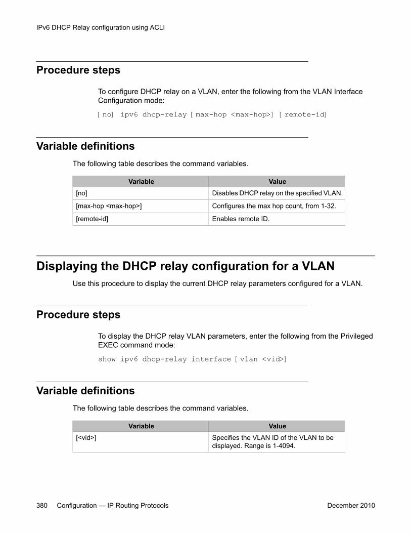
Procedure steps
To configure DHCP relay on a VLAN, enter the following from the VLAN InterfaceConfiguration mode:
[no] ipv6 dhcp-relay [max-hop <max-hop>] [remote-id]
Variable definitionsThe following table describes the command variables.
Variable Value[no] Disables DHCP relay on the specified VLAN.
[max-hop <max-hop>] Configures the max hop count, from 1-32.
[remote-id] Enables remote ID.
Displaying the DHCP relay configuration for a VLANUse this procedure to display the current DHCP relay parameters configured for a VLAN.
Procedure steps
To display the DHCP relay VLAN parameters, enter the following from the PrivilegedEXEC command mode:
show ipv6 dhcp-relay interface [vlan <vid>]
Variable definitionsThe following table describes the command variables.
Variable Value[<vid>] Specifies the VLAN ID of the VLAN to be
displayed. Range is 1-4094.
IPv6 DHCP Relay configuration using ACLI
380 Configuration — IP Routing Protocols December 2010

Job aidThe following table shows the field descriptions for the show ipv6 dhcp-relay command.
Field DescriptionVLAN ID Indicates the VLAN ID
IfIndex Indicates the VLAN interface index.
MAX HOP Indicates the maximum hop value.
DHCP-RELAY Indicates whether DHCP relay is enabled onthe VLAN.
REMOTE ID Indicates whether Remote ID is enabled onthe VLAN.
Displaying DHCP relay countersUse this procedure to display the current DHCP relay counters. This includes the number ofrequests and the number of replies.
Procedure steps
To display the DHCP relay counters, enter the following from the PrivEXEC commandmode:
show ipv6 dhcp-relay counters
Job aidThe following table shows the field descriptions for the show ipv6 dhcp-relay counterscommand.
Field DescriptionINTERFACE Indicates the interface IP address of the
DHCP relay agent.
REQUESTS Indicates the number of DHCP requests.
REPLIES Indicates the number of DHCP replies.
Displaying DHCP relay counters
Configuration — IP Routing Protocols December 2010 381

IPv6 DHCP Relay configuration using ACLI
382 Configuration — IP Routing Protocols December 2010
Chapter 27: IPv6 Tunnel configuration usingACLI
This chapter describes how to use the ACLI to configure IPv6 tunnels.
Navigation• Configuring manual IPv6-in-IPv4 tunnels using the ACLI on page 383
• Displaying manual tunnel configuration on page 385
IPv6 tunnel configuration proceduresTo configure IPv6 tunnels, perform the following steps:
1. Configure the tunnel at the source and destination switch.
2. Configure static routes at the source and destination switch.
3. Optionally, configure the tunnel hop limit.
Configuring manual IPv6-in-IPv4 tunnels using the ACLICreate an IPv6-in-IPv4 tunnel to transfer traffic between IPv6 devices across an IPv4 network.To configure a manual tunnel, you must define both the local and destination IPv4 addressesand configure a static route to route traffic to the IPv6 destination. You must also configure thetunnel at both the source and destination nodes. The maximum number of tunnels is four.
Procedure steps
1. To configure the tunnel, at the source and destination nodes, enter the following inGlobal Configuration mode:
Configuration — IP Routing Protocols December 2010 383
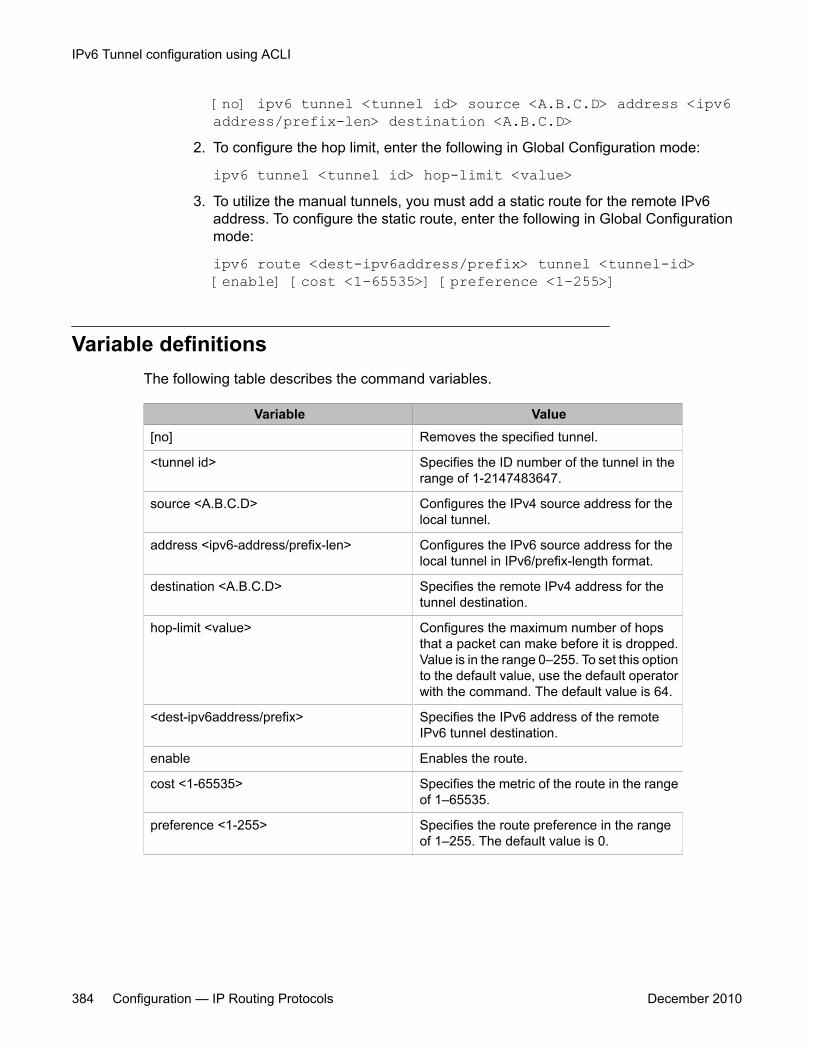
[no] ipv6 tunnel <tunnel id> source <A.B.C.D> address <ipv6address/prefix-len> destination <A.B.C.D>
2. To configure the hop limit, enter the following in Global Configuration mode:
ipv6 tunnel <tunnel id> hop-limit <value>3. To utilize the manual tunnels, you must add a static route for the remote IPv6
address. To configure the static route, enter the following in Global Configurationmode:
ipv6 route <dest-ipv6address/prefix> tunnel <tunnel-id>[enable] [cost <1-65535>] [preference <1-255>]
Variable definitionsThe following table describes the command variables.
Variable Value[no] Removes the specified tunnel.
<tunnel id> Specifies the ID number of the tunnel in therange of 1-2147483647.
source <A.B.C.D> Configures the IPv4 source address for thelocal tunnel.
address <ipv6-address/prefix-len> Configures the IPv6 source address for thelocal tunnel in IPv6/prefix-length format.
destination <A.B.C.D> Specifies the remote IPv4 address for thetunnel destination.
hop-limit <value> Configures the maximum number of hopsthat a packet can make before it is dropped.Value is in the range 0–255. To set this optionto the default value, use the default operatorwith the command. The default value is 64.
<dest-ipv6address/prefix> Specifies the IPv6 address of the remoteIPv6 tunnel destination.
enable Enables the route.
cost <1-65535> Specifies the metric of the route in the rangeof 1–65535.
preference <1-255> Specifies the route preference in the rangeof 1–255. The default value is 0.
IPv6 Tunnel configuration using ACLI
384 Configuration — IP Routing Protocols December 2010
Displaying manual tunnel configurationUse the following procedure to display the manual tunnel configuration.
Procedure steps
To display the configured tunnel, enter the following in PrivExec mode:
show ipv6 tunnel [<tunnel-id>]
Displaying manual tunnel configuration
Configuration — IP Routing Protocols December 2010 385

IPv6 Tunnel configuration using ACLI
386 Configuration — IP Routing Protocols December 2010
Chapter 28: IP routing configuration usingEnterprise Device Manager
This chapter describes the procedures you can use to configure routable VLANs using Enterprise DeviceManager (EDM).
The Avaya Ethernet Routing Switch 5000 Series are Layer 3 (L3) switches. This means that a regularLayer 2 VLAN becomes a routable Layer 3 VLAN if an IP address and MAC address are attached to theVLAN. When routing is enabled in Layer 3 mode, every Layer 3 VLAN is capable of routing as well ascarrying the management traffic. You can use any Layer 3 VLAN instead of the Management VLAN tomanage the switch.
Prerequisites• Open one of the supported browsers.
• Enter the IP address of the switch to open an EDM session.
Configuring IP routing using EDMUse the following procedure to configure IP routing on VLANs.
1. Enable IP routing globally.
2. Assign an IP address to a specific VLAN.
In the above procedure, you are not required to enable IP routing as the first step. All IP routingparameters can be configured on the Avaya Ethernet Routing Switch 5000 Series beforerouting is actually enabled on the switch.
Configuration — IP Routing Protocols December 2010 387
Navigation• Configuring global IP routing status and ARP lifetime using EDM on page 388
• Configuring an IP address and enabling routing for a VLAN using EDM on page 389
• Displaying configured IP Addresses using EDM on page 390
Configuring global IP routing status and ARP lifetime usingEDM
Use the following procedure to enable and disable global routing at the switch level. By default,routing is disabled.
Prerequisites
• Open one of the supported browsers.
• Enter the IP address of the switch to open an EDM session.
Procedure steps
1. From the Navigation tree, double-click IP Routing.
2. In the IP Routing tree, double-click IP.
3. In the Globals tab, choose the forwarding option in the Forwarding field to enablerouting.
4. Type the ARP life time in the ARPLifeTime field.
5. Click Apply.
Variable definitionsThe following table describes the fields of the Globals tab.
IP routing configuration using Enterprise Device Manager
388 Configuration — IP Routing Protocols December 2010
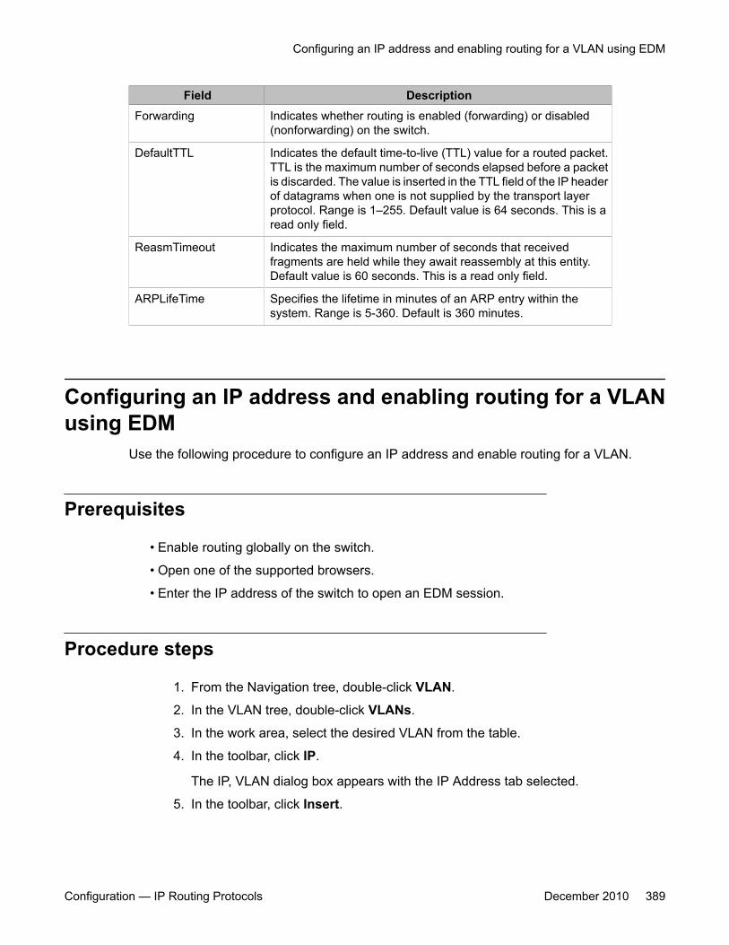
Field DescriptionForwarding Indicates whether routing is enabled (forwarding) or disabled
(nonforwarding) on the switch.
DefaultTTL Indicates the default time-to-live (TTL) value for a routed packet.TTL is the maximum number of seconds elapsed before a packetis discarded. The value is inserted in the TTL field of the IP headerof datagrams when one is not supplied by the transport layerprotocol. Range is 1–255. Default value is 64 seconds. This is aread only field.
ReasmTimeout Indicates the maximum number of seconds that receivedfragments are held while they await reassembly at this entity.Default value is 60 seconds. This is a read only field.
ARPLifeTime Specifies the lifetime in minutes of an ARP entry within thesystem. Range is 5-360. Default is 360 minutes.
Configuring an IP address and enabling routing for a VLANusing EDM
Use the following procedure to configure an IP address and enable routing for a VLAN.
Prerequisites
• Enable routing globally on the switch.
• Open one of the supported browsers.
• Enter the IP address of the switch to open an EDM session.
Procedure steps
1. From the Navigation tree, double-click VLAN.
2. In the VLAN tree, double-click VLANs.
3. In the work area, select the desired VLAN from the table.
4. In the toolbar, click IP.
The IP, VLAN dialog box appears with the IP Address tab selected.
5. In the toolbar, click Insert.
Configuring an IP address and enabling routing for a VLAN using EDM
Configuration — IP Routing Protocols December 2010 389
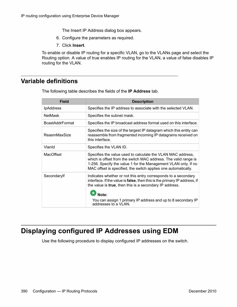
The Insert IP Address dialog box appears.
6. Configure the parameters as required.
7. Click Insert.
To enable or disable IP routing for a specific VLAN, go to the VLANs page and select theRouting option. A value of true enables IP routing for the VLAN, a value of false disables IProuting for the VLAN.
Variable definitionsThe following table describes the fields of the IP Address tab.
Field DescriptionIpAddress Specifies the IP address to associate with the selected VLAN.
NetMask Specifies the subnet mask.
BcastAddrFormat Specifies the IP broadcast address format used on this interface.
ReasmMaxSizeSpecifies the size of the largest IP datagram which this entity canreassemble from fragmented incoming IP datagrams received onthis interface.
VlanId Specifies the VLAN ID.
MacOffset Specifies the value used to calculate the VLAN MAC address,which is offset from the switch MAC address. The valid range is1-256. Specify the value 1 for the Management VLAN only. If noMAC offset is specified, the switch applies one automatically.
SecondaryIf Indicates whether or not this entry corresponds to a secondaryinterface. If the value is false, then this is the primary IP address, ifthe value is true, then this is a secondary IP address.
Note:You can assign 1 primary IP address and up to 8 secondary IPaddresses to a VLAN.
Displaying configured IP Addresses using EDMUse the following procedure to display configured IP addresses on the switch.
IP routing configuration using Enterprise Device Manager
390 Configuration — IP Routing Protocols December 2010
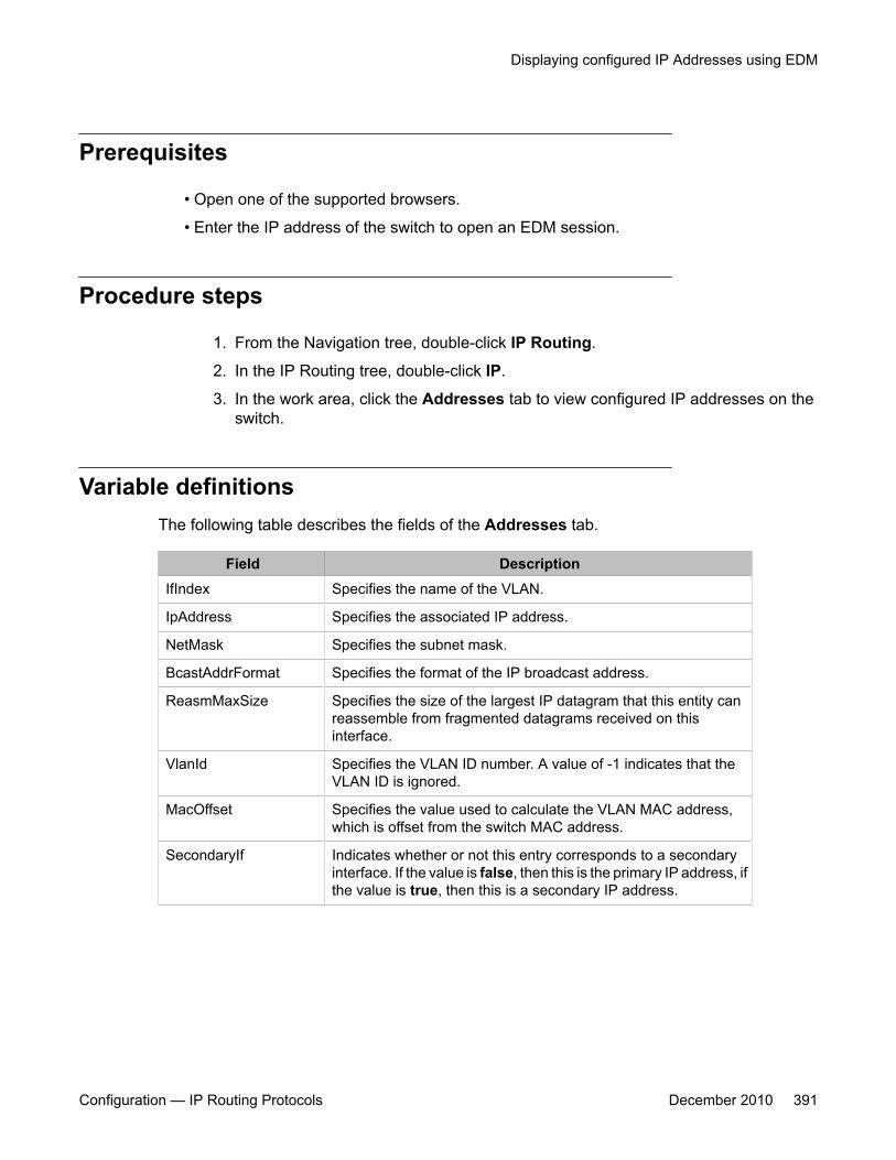
Prerequisites
• Open one of the supported browsers.
• Enter the IP address of the switch to open an EDM session.
Procedure steps
1. From the Navigation tree, double-click IP Routing.
2. In the IP Routing tree, double-click IP.
3. In the work area, click the Addresses tab to view configured IP addresses on theswitch.
Variable definitionsThe following table describes the fields of the Addresses tab.
Field DescriptionIfIndex Specifies the name of the VLAN.
IpAddress Specifies the associated IP address.
NetMask Specifies the subnet mask.
BcastAddrFormat Specifies the format of the IP broadcast address.
ReasmMaxSize Specifies the size of the largest IP datagram that this entity canreassemble from fragmented datagrams received on thisinterface.
VlanId Specifies the VLAN ID number. A value of -1 indicates that theVLAN ID is ignored.
MacOffset Specifies the value used to calculate the VLAN MAC address,which is offset from the switch MAC address.
SecondaryIf Indicates whether or not this entry corresponds to a secondaryinterface. If the value is false, then this is the primary IP address, ifthe value is true, then this is a secondary IP address.
Displaying configured IP Addresses using EDM
Configuration — IP Routing Protocols December 2010 391

IP routing configuration using Enterprise Device Manager
392 Configuration — IP Routing Protocols December 2010
Chapter 29: Static route configuration usingEnterprise Device Manager
This chapter describes the procedures you can use to configure static routes using Enterprise DeviceManager (EDM).
Prerequisites• Open one of the supported browsers.
• Enter the IP address of the switch to open an EDM session.
Navigation• Configuring static routes using EDM on page 393
• Displaying IP Routes using EDM on page 395
• Filtering route information using EDM on page 396
• Displaying TCP information for the switch using EDM on page 397
• Displaying TCP Connections using EDM on page 398
• Displaying TCP Listeners using EDM on page 399
• Displaying UDP endpoints using EDM on page 400
Configuring static routes using EDMUse the following procedure to configure static routes for the switch.
Configuration — IP Routing Protocols December 2010 393

Prerequisites
• Open one of the supported browsers.
• Enter the IP address of the switch to open an EDM session.
• Enable IP routing globally.
• Enable IP routing and configure an IP address on the VLANs to be routed.
Procedure steps
1. From the navigation tree, double-click IP Routing.
2. In the IP Routing tree, double-click IP.
3. In the work area, select the Static Routes tab.
4. In the toolbar, click Insert.
The Insert Static Routes dialog box appears.
5. Configure the parameters as required.
6. Click Insert.
The new static route is updated in the work area.
Variable definitionsThe following table describes the fields of the Static Routes tab.
Field DescriptionDest Specifies the destination IP address of the route. 0.0.0.0 is
considered the default route.
Mask Specifies the destination mask of the route.
NextHop Specifies the IP address of the next hop of this route.
Metric Represents the cost of the static route. It is used to choose thebest route (the one with the smallest cost) to a certain destination.The range is 1-65535.
IfIndex Specifies the interface on which the static route is configured.
Enable Specifies whether the route is administratively enabled (true) ordisabled (false).
Static route configuration using Enterprise Device Manager
394 Configuration — IP Routing Protocols December 2010

Field DescriptionStatus Specifies the operational status of the route (inactive or active).
Displaying IP Routes using EDMUse the following procedure to display the different routes known to the switch.
Routes are not be displayed until at least one port in the VLAN has link.
Prerequisites
• Open one of the supported browsers.
• Enter the IP address of the switch to open an EDM session.
Procedure steps
1. From the navigation tree, double-click IP Routing.
2. In the IP Routing tree, double-click IP.
3. In the work area, select the Routes tab.
Variable definitionsThe following table describes the fields of the Routes tab.
Field DescriptionDest Specifies the destination address of the route.
Mask Specifies the subnet mask used by the route destination.
NextHop Specifies the next hop in the listed route.
HopOrMetric Specifies the RIP hop count, OSPF cost, or metric associated withthe route.
Interface Specifies the interface associated with the route.
Proto Specifies the protocol associated with the route.
PathType Specifies the route path type:
Displaying IP Routes using EDM
Configuration — IP Routing Protocols December 2010 395

Field Description
• i: indirect
• d: direct
• A: alternative
• B: best
• E: ECMP
• U: unresolved
Pref Specifies the preference value associated with the route.
Filtering route information using EDMUse the following procedure to filter the Routes tab to display only the desired switch routes.
Procedure steps
1. From the navigation tree, double-click IP Routing.
2. In the IP Routing tree, double-click IP.
3. In the work area, select the Routes tab.
4. In the toolbar, click Filter.
The Filter dialog box appears.
Variable definitions
The following table describes the fields of the Filter tab.
Field DescriptionCondition When using multiple filter expressions on the tab, this is the
condition that is used to join them together.
Ignore Case Denotes whether filters are case sensitive or insensitive.
Column Denotes the type of criteria that will be applied to values used forfiltering.
All Records Clears the filters, and displays all rows.
Dest Select this check box and enter a value to filter on the routedestination value.
Static route configuration using Enterprise Device Manager
396 Configuration — IP Routing Protocols December 2010
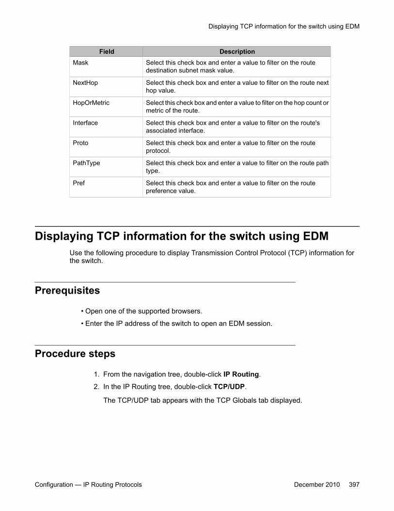
Field DescriptionMask Select this check box and enter a value to filter on the route
destination subnet mask value.
NextHop Select this check box and enter a value to filter on the route nexthop value.
HopOrMetric Select this check box and enter a value to filter on the hop count ormetric of the route.
Interface Select this check box and enter a value to filter on the route'sassociated interface.
Proto Select this check box and enter a value to filter on the routeprotocol.
PathType Select this check box and enter a value to filter on the route pathtype.
Pref Select this check box and enter a value to filter on the routepreference value.
Displaying TCP information for the switch using EDMUse the following procedure to display Transmission Control Protocol (TCP) information forthe switch.
Prerequisites
• Open one of the supported browsers.
• Enter the IP address of the switch to open an EDM session.
Procedure steps
1. From the navigation tree, double-click IP Routing.
2. In the IP Routing tree, double-click TCP/UDP.
The TCP/UDP tab appears with the TCP Globals tab displayed.
Displaying TCP information for the switch using EDM
Configuration — IP Routing Protocols December 2010 397

Variable definitionsThe following table describes the fields of the TCP Globals tab.
Field DescriptionRtoAlgorithm Specifies the algorithm used to determine the timeout value used
for retransmitting unacknowledged octets.
RtoMin Specifies the minimum value permitted by a TCP implementationfor the retransmission timeout, measured in milliseconds.
RtoMax Specifies the maximum value permitted by a TCP implementationfor the retransmission timeout, measured in milliseconds.
MaxConn Specifies the limit on the total number of TCP connections thatthe entity can support. In entities where the maximum number ofconnections is dynamic, this object contains the value -1.
Displaying TCP Connections using EDMUse the following procedure to display information on the current TCP connections the switchmaintains.
Prerequisites
• Open one of the supported browsers.
• Enter the IP address of the switch to open an EDM session.
Procedure steps
1. From the navigation tree, double-click IP Routing.
2. In the IP Routing tree, double-click TCP/UDP.
3. In the work area, click the TCP Connections tab.
Variable definitionsThe following table describes the fields of the TCP Connections tab.
Static route configuration using Enterprise Device Manager
398 Configuration — IP Routing Protocols December 2010
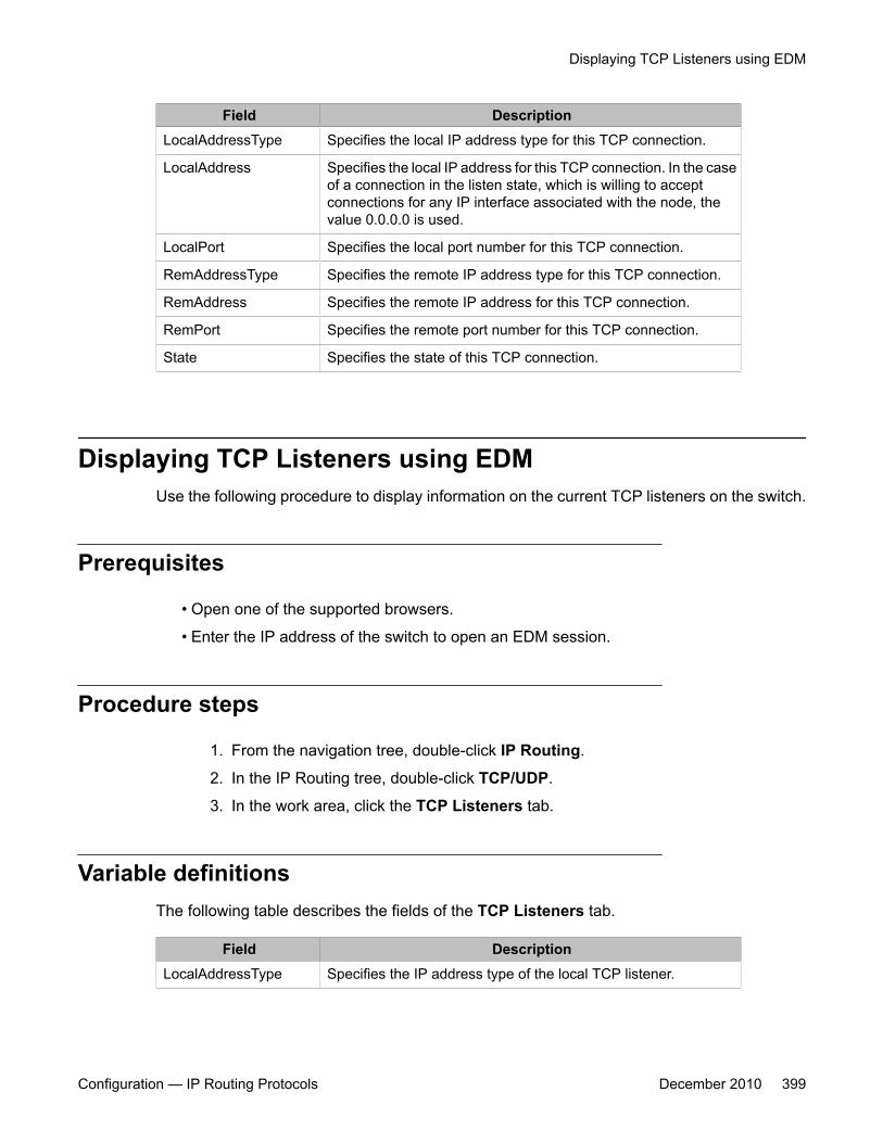
Field DescriptionLocalAddressType Specifies the local IP address type for this TCP connection.
LocalAddress Specifies the local IP address for this TCP connection. In the caseof a connection in the listen state, which is willing to acceptconnections for any IP interface associated with the node, thevalue 0.0.0.0 is used.
LocalPort Specifies the local port number for this TCP connection.
RemAddressType Specifies the remote IP address type for this TCP connection.
RemAddress Specifies the remote IP address for this TCP connection.
RemPort Specifies the remote port number for this TCP connection.
State Specifies the state of this TCP connection.
Displaying TCP Listeners using EDMUse the following procedure to display information on the current TCP listeners on the switch.
Prerequisites
• Open one of the supported browsers.
• Enter the IP address of the switch to open an EDM session.
Procedure steps
1. From the navigation tree, double-click IP Routing.
2. In the IP Routing tree, double-click TCP/UDP.
3. In the work area, click the TCP Listeners tab.
Variable definitionsThe following table describes the fields of the TCP Listeners tab.
Field DescriptionLocalAddressType Specifies the IP address type of the local TCP listener.
Displaying TCP Listeners using EDM
Configuration — IP Routing Protocols December 2010 399
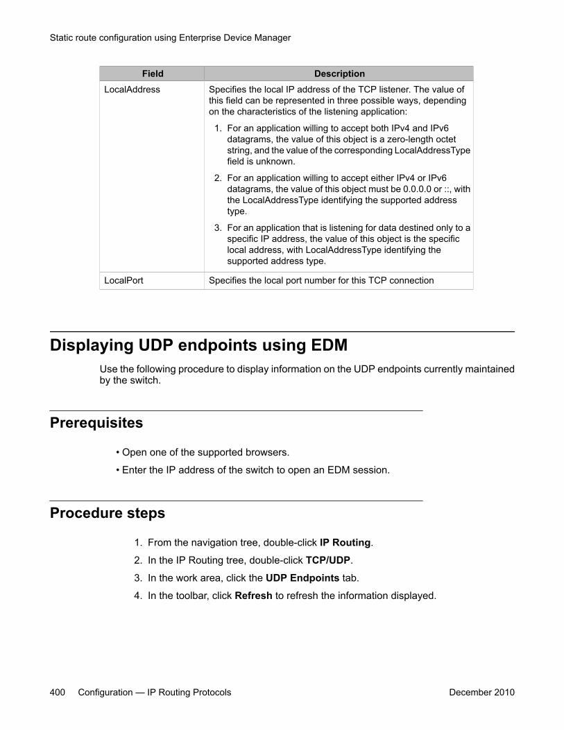
Field DescriptionLocalAddress Specifies the local IP address of the TCP listener. The value of
this field can be represented in three possible ways, dependingon the characteristics of the listening application:
1. For an application willing to accept both IPv4 and IPv6datagrams, the value of this object is a zero-length octetstring, and the value of the corresponding LocalAddressTypefield is unknown.
2. For an application willing to accept either IPv4 or IPv6datagrams, the value of this object must be 0.0.0.0 or ::, withthe LocalAddressType identifying the supported addresstype.
3. For an application that is listening for data destined only to aspecific IP address, the value of this object is the specificlocal address, with LocalAddressType identifying thesupported address type.
LocalPort Specifies the local port number for this TCP connection
Displaying UDP endpoints using EDMUse the following procedure to display information on the UDP endpoints currently maintainedby the switch.
Prerequisites
• Open one of the supported browsers.
• Enter the IP address of the switch to open an EDM session.
Procedure steps
1. From the navigation tree, double-click IP Routing.
2. In the IP Routing tree, double-click TCP/UDP.
3. In the work area, click the UDP Endpoints tab.
4. In the toolbar, click Refresh to refresh the information displayed.
Static route configuration using Enterprise Device Manager
400 Configuration — IP Routing Protocols December 2010
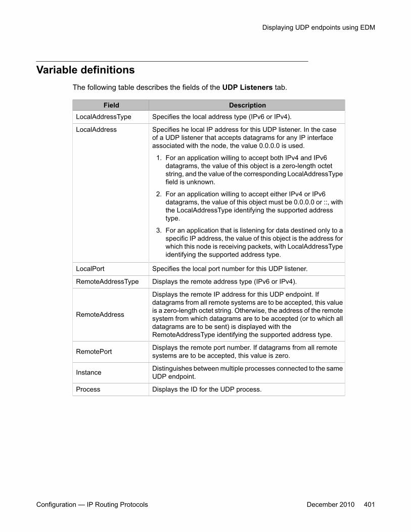
Variable definitionsThe following table describes the fields of the UDP Listeners tab.
Field DescriptionLocalAddressType Specifies the local address type (IPv6 or IPv4).
LocalAddress Specifies he local IP address for this UDP listener. In the caseof a UDP listener that accepts datagrams for any IP interfaceassociated with the node, the value 0.0.0.0 is used.
1. For an application willing to accept both IPv4 and IPv6datagrams, the value of this object is a zero-length octetstring, and the value of the corresponding LocalAddressTypefield is unknown.
2. For an application willing to accept either IPv4 or IPv6datagrams, the value of this object must be 0.0.0.0 or ::, withthe LocalAddressType identifying the supported addresstype.
3. For an application that is listening for data destined only to aspecific IP address, the value of this object is the address forwhich this node is receiving packets, with LocalAddressTypeidentifying the supported address type.
LocalPort Specifies the local port number for this UDP listener.
RemoteAddressType Displays the remote address type (IPv6 or IPv4).
RemoteAddress
Displays the remote IP address for this UDP endpoint. Ifdatagrams from all remote systems are to be accepted, this valueis a zero-length octet string. Otherwise, the address of the remotesystem from which datagrams are to be accepted (or to which alldatagrams are to be sent) is displayed with theRemoteAddressType identifying the supported address type.
RemotePort Displays the remote port number. If datagrams from all remotesystems are to be accepted, this value is zero.
Instance Distinguishes between multiple processes connected to the sameUDP endpoint.
Process Displays the ID for the UDP process.
Displaying UDP endpoints using EDM
Configuration — IP Routing Protocols December 2010 401

Static route configuration using Enterprise Device Manager
402 Configuration — IP Routing Protocols December 2010
Chapter 30: Brouter port configuration usingEnterprise Device Manager
This chapter describes the procedure you can use to configure a brouter port using Enterprise DeviceManager (EDM).
A brouter port is a single-port VLAN that can route IP packets as well as bridge all non-routable traffic.The following section describes the procedures necessary to configure and manage brouter ports on theAvaya Ethernet Routing Switch 5000 Series using EDM.
In EDM, brouter ports are treated as routable VLANs and are displayed on the Basic tab of the VLANsdialog box.
Prerequisites• Open one of the supported browsers.
• Enter the IP address of the switch to open an EDM session.
Configuring a brouter port using EDMUse the following procedure to configure and manage brouter ports.
Prerequisites
• Open one of the supported browsers.
• Enter the IP address of the switch to open an EDM session.
Procedure steps
1. In the Device Physical View, select a port .
2. Right-click the selected port.
Configuration — IP Routing Protocols December 2010 403

3. Select Edit from the shortcut menu.
The Port tab appears.
4. In the work area, click the IP Address tab.
5. In the toolbar, click Insert.
The Insert IP Address dialog appears.
6. Using the provided fields, create the new brouter port.
7. Click Insert.
Variable definitionsThe following table describes the fields of the IP Address tab.
Field DescriptionIpAddress Specifies the IP address assigned to this brouter.
NetMask Specifies the subnet mask associated with the brouter IPaddress.
BcastAddrFormat Specifies the IP broadcast address format used on thisinterface.
ReasmMaxSize Specifies the size of the largest IP datagram which thisentity can reassemble from incoming IP fragmenteddatagrams received on this interface.
VlanId Specifies the VLAN ID associated with this brouter port.
MacOffset Specifies the MAC address offset associated with thisbrouter port.
Brouter port configuration using Enterprise Device Manager
404 Configuration — IP Routing Protocols December 2010

Chapter 31: OSPF configuration usingEnterprise Device Manager
This chapter describes the procedures you can use to configure OSPF using Enterprise Device Manager(EDM).
The Open Shortest Path First (OSPF) Protocol is an Interior Gateway Protocol (IGP) that distributesrouting information between routers belonging to a single autonomous system (AS). Intended for use inlarge networks, OSPF is a link-state protocol which supports IP subnetting and the tagging of externally-derived routing information.
Prerequisites• Install the Advanced License.
• Enable IP routing globally on the switch.
• Assign an IP address to the VLAN that you want to enable with OSPF.
Routing is automatically enabled on the VLAN when you assign an IP address to it.
Navigation• Configuring Global OSPF properties using EDM on page 406
• Configuring an OSPF area using EDM on page 408
• Configuring an area aggregate range using EDM on page 410
• Configuring OSPF stub area metrics using EDM on page 412
• Configuring OSPF interfaces using EDM on page 413
• Configuring OSPF interface metrics using EDM on page 415
• Defining MD5 keys for OSPF interfaces using EDM on page 416
• Displaying OSPF neighbor information using EDM on page 417
• Configuring an OSPF virtual link using EDM on page 418
• Configuring an automatic virtual link using EDM on page 408
Configuration — IP Routing Protocols December 2010 405

• Defining MD5 keys for OSPF virtual links using EDM on page 420
• Displaying virtual neighbor information using EDM on page 421
• Configuring OSPF host routes using EDM on page 423
• Displaying link state database information using EDM on page 424
• Displaying external link state database information using EDM on page 425
• Displaying OSPF statistics using EDM on page 426
• Displaying VLAN OSPF statistics using EDM on page 428
Configuring Global OSPF properties using EDMUse the following procedure to configure global OSPF parameters.
Prerequisites
• Install the Advanced License.
• Enable IP routing globally on the switch.
• Assign an IP address to the VLAN that you want to enable with OSPF.
Routing is automatically enabled on the VLAN when you assign an IP address to it.
Procedure steps
1. From the navigation tree, double-click IP Routing.
2. In the IP Routing tree, double-click OSPF.
3. In the General tab, configure the parameters as required.
4. In the toolbar, click Apply.
Variable definitionsThe following table describes the fields of the General tab.
Field DescriptionRouterId Specifies the unique ID of the router in the Autonomous
System.
OSPF configuration using Enterprise Device Manager
406 Configuration — IP Routing Protocols December 2010
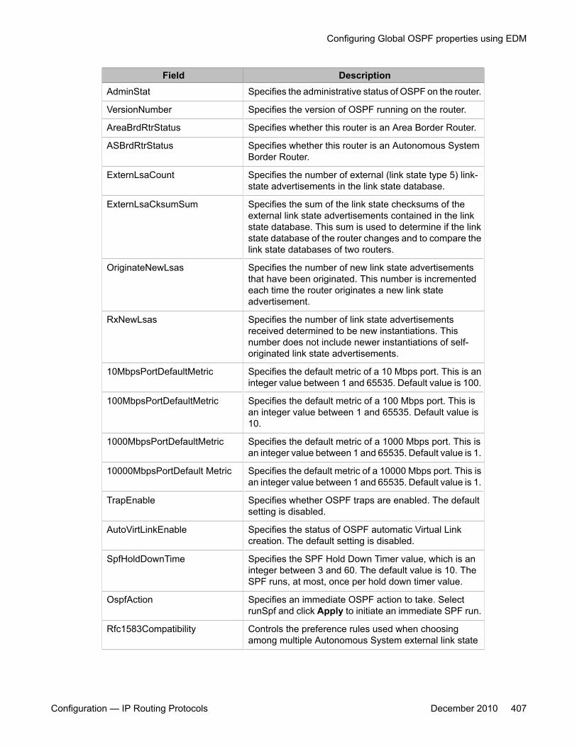
Field DescriptionAdminStat Specifies the administrative status of OSPF on the router.
VersionNumber Specifies the version of OSPF running on the router.
AreaBrdRtrStatus Specifies whether this router is an Area Border Router.
ASBrdRtrStatus Specifies whether this router is an Autonomous SystemBorder Router.
ExternLsaCount Specifies the number of external (link state type 5) link-state advertisements in the link state database.
ExternLsaCksumSum Specifies the sum of the link state checksums of theexternal link state advertisements contained in the linkstate database. This sum is used to determine if the linkstate database of the router changes and to compare thelink state databases of two routers.
OriginateNewLsas Specifies the number of new link state advertisementsthat have been originated. This number is incrementedeach time the router originates a new link stateadvertisement.
RxNewLsas Specifies the number of link state advertisementsreceived determined to be new instantiations. Thisnumber does not include newer instantiations of self-originated link state advertisements.
10MbpsPortDefaultMetric Specifies the default metric of a 10 Mbps port. This is aninteger value between 1 and 65535. Default value is 100.
100MbpsPortDefaultMetric Specifies the default metric of a 100 Mbps port. This isan integer value between 1 and 65535. Default value is10.
1000MbpsPortDefaultMetric Specifies the default metric of a 1000 Mbps port. This isan integer value between 1 and 65535. Default value is 1.
10000MbpsPortDefault Metric Specifies the default metric of a 10000 Mbps port. This isan integer value between 1 and 65535. Default value is 1.
TrapEnable Specifies whether OSPF traps are enabled. The defaultsetting is disabled.
AutoVirtLinkEnable Specifies the status of OSPF automatic Virtual Linkcreation. The default setting is disabled.
SpfHoldDownTime Specifies the SPF Hold Down Timer value, which is aninteger between 3 and 60. The default value is 10. TheSPF runs, at most, once per hold down timer value.
OspfAction Specifies an immediate OSPF action to take. SelectrunSpf and click Apply to initiate an immediate SPF run.
Rfc1583Compatibility Controls the preference rules used when choosingamong multiple Autonomous System external link state
Configuring Global OSPF properties using EDM
Configuration — IP Routing Protocols December 2010 407
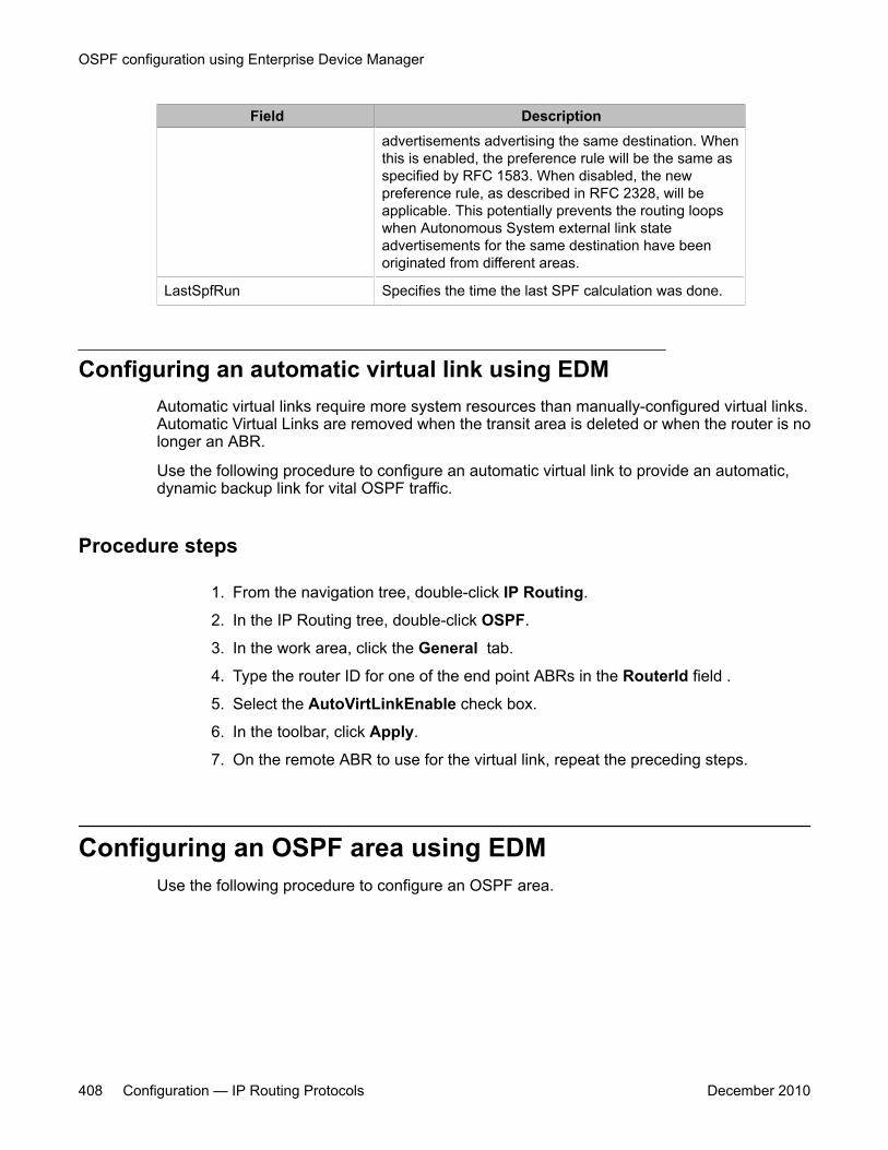
Field Descriptionadvertisements advertising the same destination. Whenthis is enabled, the preference rule will be the same asspecified by RFC 1583. When disabled, the newpreference rule, as described in RFC 2328, will beapplicable. This potentially prevents the routing loopswhen Autonomous System external link stateadvertisements for the same destination have beenoriginated from different areas.
LastSpfRun Specifies the time the last SPF calculation was done.
Configuring an automatic virtual link using EDMAutomatic virtual links require more system resources than manually-configured virtual links.Automatic Virtual Links are removed when the transit area is deleted or when the router is nolonger an ABR.
Use the following procedure to configure an automatic virtual link to provide an automatic,dynamic backup link for vital OSPF traffic.
Procedure steps
1. From the navigation tree, double-click IP Routing.
2. In the IP Routing tree, double-click OSPF.
3. In the work area, click the General tab.
4. Type the router ID for one of the end point ABRs in the RouterId field .
5. Select the AutoVirtLinkEnable check box.
6. In the toolbar, click Apply.
7. On the remote ABR to use for the virtual link, repeat the preceding steps.
Configuring an OSPF area using EDMUse the following procedure to configure an OSPF area.
OSPF configuration using Enterprise Device Manager
408 Configuration — IP Routing Protocols December 2010
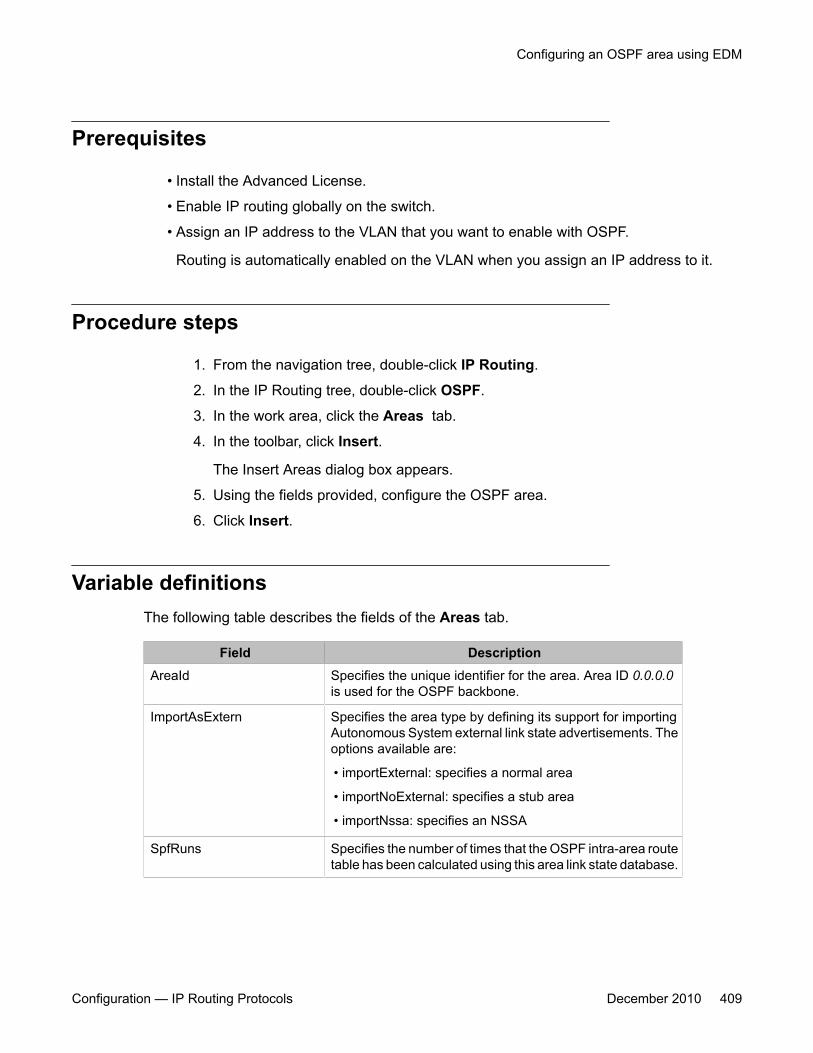
Prerequisites
• Install the Advanced License.
• Enable IP routing globally on the switch.
• Assign an IP address to the VLAN that you want to enable with OSPF.
Routing is automatically enabled on the VLAN when you assign an IP address to it.
Procedure steps
1. From the navigation tree, double-click IP Routing.
2. In the IP Routing tree, double-click OSPF.
3. In the work area, click the Areas tab.
4. In the toolbar, click Insert.
The Insert Areas dialog box appears.
5. Using the fields provided, configure the OSPF area.
6. Click Insert.
Variable definitionsThe following table describes the fields of the Areas tab.
Field DescriptionAreaId Specifies the unique identifier for the area. Area ID 0.0.0.0
is used for the OSPF backbone.
ImportAsExtern Specifies the area type by defining its support for importingAutonomous System external link state advertisements. Theoptions available are:
• importExternal: specifies a normal area
• importNoExternal: specifies a stub area
• importNssa: specifies an NSSA
SpfRuns Specifies the number of times that the OSPF intra-area routetable has been calculated using this area link state database.
Configuring an OSPF area using EDM
Configuration — IP Routing Protocols December 2010 409

Field DescriptionAreaBdrRtrCount Specifies the total number of Area Border Routers reachable
within this area. This is initially zero and is calculated in eachSPF pass.
AsBdrRtrCount Specifies the total number of Autonomous System BorderRouters reachable within this area. This is initially zero, andis calculated in each SPF pass.
AreaLsaCount Specifies the total number of link state advertisements in thisarea's link state database, excluding Autonomous Systemexternal link state advertisements.
AreaLsaCksumSum Specifies the sum of the link state advertisements'checksums contained in this area's link state database. Thissum excludes external (link state type 5) link stateadvertisements. The sum can be used to determine if therehas been a change in a router's link state database, and tocompare the link state database of two routers.
AreaSummary Controls the import of summary link state advertisements onan ABR into a stub area. It has no effect on other areas. Ifthe value is noAreaSummary, the ABR neither originates norpropagates summary link state advertisements into the stubarea (creating a totally stubby area). If the value issendAreaSummary, the ABR both summarizes andpropagates summary link state advertisements.
Configuring an area aggregate range using EDMUse the following procedure to configure OSPF area aggregate ranges to reduce the number oflink state advertisements that are required within the area. You can also controladvertisements.
Prerequisites
• Install the Advanced License.
• Enable IP routing globally on the switch.
• Assign an IP address to the VLAN that you want to enable with OSPF.
Routing is automatically enabled on the VLAN when you assign an IP address to it.
OSPF configuration using Enterprise Device Manager
410 Configuration — IP Routing Protocols December 2010
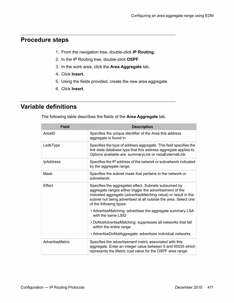
Procedure steps
1. From the navigation tree, double-click IP Routing.
2. In the IP Routing tree, double-click OSPF.
3. In the work area, click the Area Aggregate tab.
4. Click Insert.
5. Using the fields provided, create the new area aggregate.
6. Click Insert.
Variable definitionsThe following table describes the fields of the Area Aggregate tab.
Field DescriptionAreaID Specifies the unique identifier of the Area this address
aggregate is found in.
LsdbType Specifies the type of address aggregate. This field specifies thelink state database type that this address aggregate applies to.Options available are: summaryLink or nssaExternalLink.
IpAddress Specifies the IP address of the network or subnetwork indicatedby the aggregate range.
Mask Specifies the subnet mask that pertains to the network orsubnetwork.
Effect Specifies the aggregates effect. Subnets subsumed byaggregate ranges either trigger the advertisement of theindicated aggregate (advertiseMatching value) or result in thesubnet not being advertised at all outside the area. Select oneof the following types:
• AdvertiseMatching: advertises the aggregate summary LSAwith the same LSID
• DoNotAdvertiseMatching: suppresses all networks that fallwithin the entire range
• AdvertiseDoNotAggregate: advertises individual networks
AdvertiseMetric Specifies the advertisement metric associated with thisaggregate. Enter an integer value between 0 and 65535 whichrepresents the Metric cost value for the OSPF area range.
Configuring an area aggregate range using EDM
Configuration — IP Routing Protocols December 2010 411
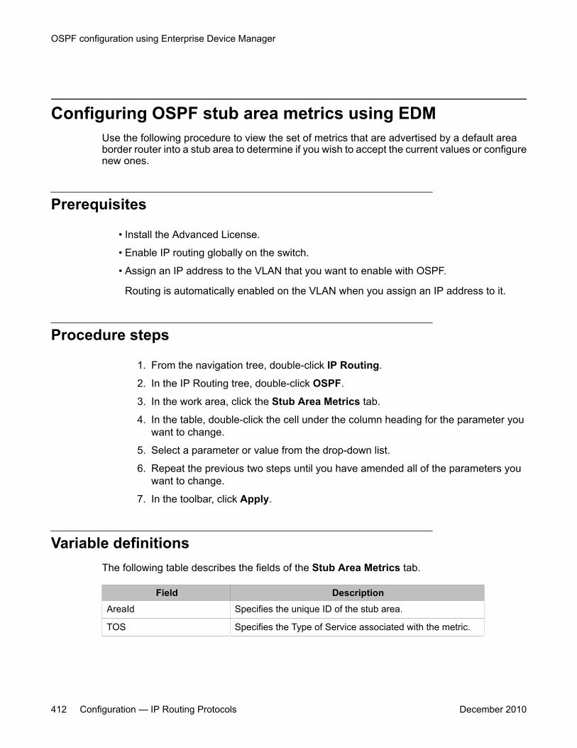
Configuring OSPF stub area metrics using EDMUse the following procedure to view the set of metrics that are advertised by a default areaborder router into a stub area to determine if you wish to accept the current values or configurenew ones.
Prerequisites
• Install the Advanced License.
• Enable IP routing globally on the switch.
• Assign an IP address to the VLAN that you want to enable with OSPF.
Routing is automatically enabled on the VLAN when you assign an IP address to it.
Procedure steps
1. From the navigation tree, double-click IP Routing.
2. In the IP Routing tree, double-click OSPF.
3. In the work area, click the Stub Area Metrics tab.
4. In the table, double-click the cell under the column heading for the parameter youwant to change.
5. Select a parameter or value from the drop-down list.
6. Repeat the previous two steps until you have amended all of the parameters youwant to change.
7. In the toolbar, click Apply.
Variable definitionsThe following table describes the fields of the Stub Area Metrics tab.
Field DescriptionAreaId Specifies the unique ID of the stub area.
TOS Specifies the Type of Service associated with the metric.
OSPF configuration using Enterprise Device Manager
412 Configuration — IP Routing Protocols December 2010
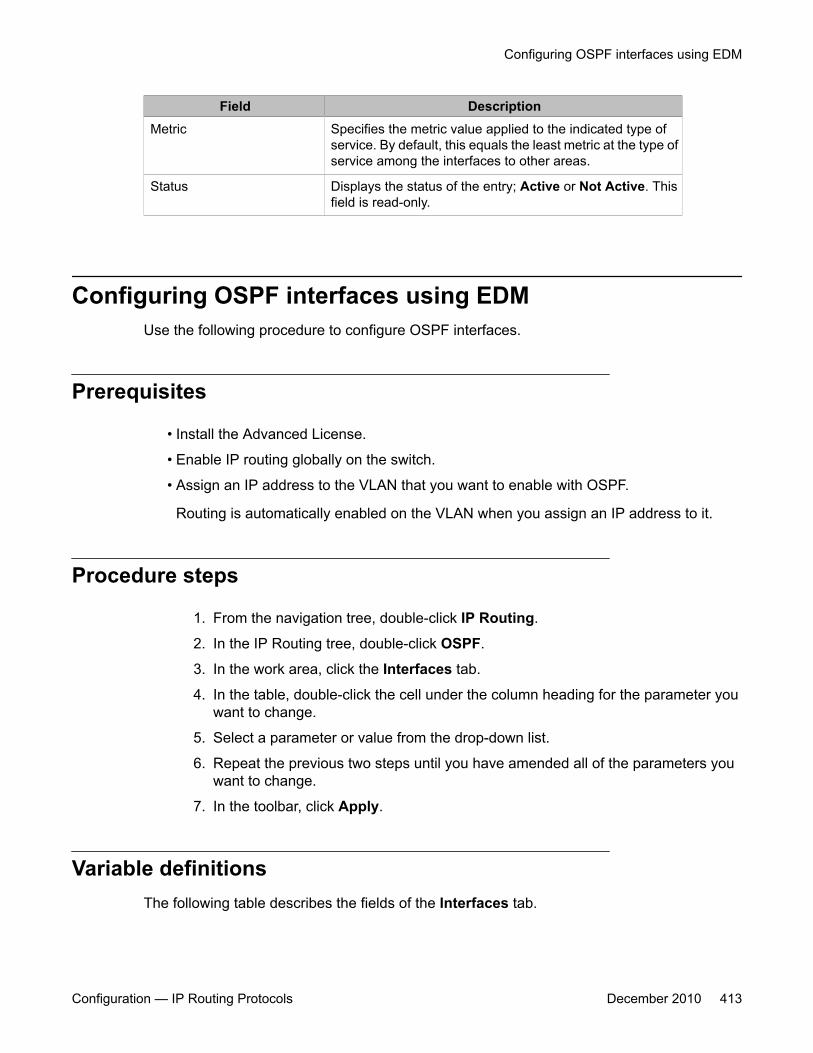
Field DescriptionMetric Specifies the metric value applied to the indicated type of
service. By default, this equals the least metric at the type ofservice among the interfaces to other areas.
Status Displays the status of the entry; Active or Not Active. Thisfield is read-only.
Configuring OSPF interfaces using EDMUse the following procedure to configure OSPF interfaces.
Prerequisites
• Install the Advanced License.
• Enable IP routing globally on the switch.
• Assign an IP address to the VLAN that you want to enable with OSPF.
Routing is automatically enabled on the VLAN when you assign an IP address to it.
Procedure steps
1. From the navigation tree, double-click IP Routing.
2. In the IP Routing tree, double-click OSPF.
3. In the work area, click the Interfaces tab.
4. In the table, double-click the cell under the column heading for the parameter youwant to change.
5. Select a parameter or value from the drop-down list.
6. Repeat the previous two steps until you have amended all of the parameters youwant to change.
7. In the toolbar, click Apply.
Variable definitionsThe following table describes the fields of the Interfaces tab.
Configuring OSPF interfaces using EDM
Configuration — IP Routing Protocols December 2010 413
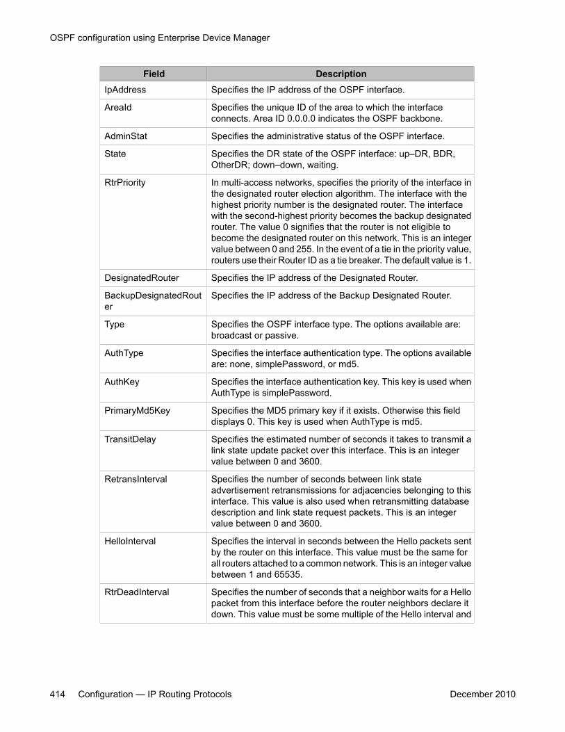
Field DescriptionIpAddress Specifies the IP address of the OSPF interface.
AreaId Specifies the unique ID of the area to which the interfaceconnects. Area ID 0.0.0.0 indicates the OSPF backbone.
AdminStat Specifies the administrative status of the OSPF interface.
State Specifies the DR state of the OSPF interface: up–DR, BDR,OtherDR; down–down, waiting.
RtrPriority In multi-access networks, specifies the priority of the interface inthe designated router election algorithm. The interface with thehighest priority number is the designated router. The interfacewith the second-highest priority becomes the backup designatedrouter. The value 0 signifies that the router is not eligible tobecome the designated router on this network. This is an integervalue between 0 and 255. In the event of a tie in the priority value,routers use their Router ID as a tie breaker. The default value is 1.
DesignatedRouter Specifies the IP address of the Designated Router.
BackupDesignatedRouter
Specifies the IP address of the Backup Designated Router.
Type Specifies the OSPF interface type. The options available are:broadcast or passive.
AuthType Specifies the interface authentication type. The options availableare: none, simplePassword, or md5.
AuthKey Specifies the interface authentication key. This key is used whenAuthType is simplePassword.
PrimaryMd5Key Specifies the MD5 primary key if it exists. Otherwise this fielddisplays 0. This key is used when AuthType is md5.
TransitDelay Specifies the estimated number of seconds it takes to transmit alink state update packet over this interface. This is an integervalue between 0 and 3600.
RetransInterval Specifies the number of seconds between link stateadvertisement retransmissions for adjacencies belonging to thisinterface. This value is also used when retransmitting databasedescription and link state request packets. This is an integervalue between 0 and 3600.
HelloInterval Specifies the interval in seconds between the Hello packets sentby the router on this interface. This value must be the same forall routers attached to a common network. This is an integer valuebetween 1 and 65535.
RtrDeadInterval Specifies the number of seconds that a neighbor waits for a Hellopacket from this interface before the router neighbors declare itdown. This value must be some multiple of the Hello interval and
OSPF configuration using Enterprise Device Manager
414 Configuration — IP Routing Protocols December 2010
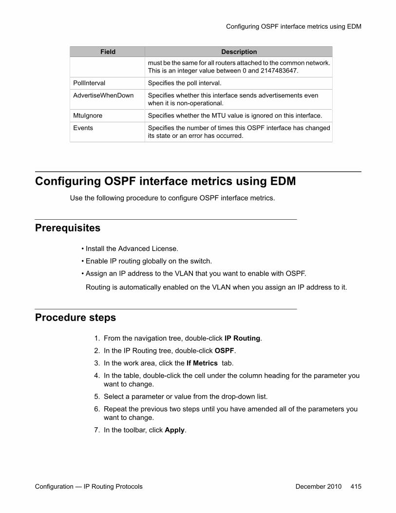
Field Descriptionmust be the same for all routers attached to the common network.This is an integer value between 0 and 2147483647.
PollInterval Specifies the poll interval.
AdvertiseWhenDown Specifies whether this interface sends advertisements evenwhen it is non-operational.
MtuIgnore Specifies whether the MTU value is ignored on this interface.
Events Specifies the number of times this OSPF interface has changedits state or an error has occurred.
Configuring OSPF interface metrics using EDMUse the following procedure to configure OSPF interface metrics.
Prerequisites
• Install the Advanced License.
• Enable IP routing globally on the switch.
• Assign an IP address to the VLAN that you want to enable with OSPF.
Routing is automatically enabled on the VLAN when you assign an IP address to it.
Procedure steps
1. From the navigation tree, double-click IP Routing.
2. In the IP Routing tree, double-click OSPF.
3. In the work area, click the If Metrics tab.
4. In the table, double-click the cell under the column heading for the parameter youwant to change.
5. Select a parameter or value from the drop-down list.
6. Repeat the previous two steps until you have amended all of the parameters youwant to change.
7. In the toolbar, click Apply.
Configuring OSPF interface metrics using EDM
Configuration — IP Routing Protocols December 2010 415
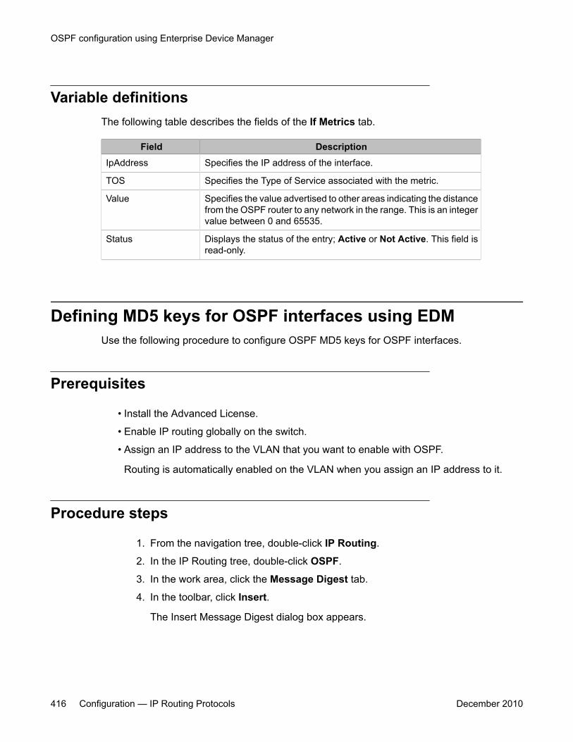
Variable definitionsThe following table describes the fields of the If Metrics tab.
Field DescriptionIpAddress Specifies the IP address of the interface.
TOS Specifies the Type of Service associated with the metric.
Value Specifies the value advertised to other areas indicating the distancefrom the OSPF router to any network in the range. This is an integervalue between 0 and 65535.
Status Displays the status of the entry; Active or Not Active. This field isread-only.
Defining MD5 keys for OSPF interfaces using EDMUse the following procedure to configure OSPF MD5 keys for OSPF interfaces.
Prerequisites
• Install the Advanced License.
• Enable IP routing globally on the switch.
• Assign an IP address to the VLAN that you want to enable with OSPF.
Routing is automatically enabled on the VLAN when you assign an IP address to it.
Procedure steps
1. From the navigation tree, double-click IP Routing.
2. In the IP Routing tree, double-click OSPF.
3. In the work area, click the Message Digest tab.
4. In the toolbar, click Insert.
The Insert Message Digest dialog box appears.
OSPF configuration using Enterprise Device Manager
416 Configuration — IP Routing Protocols December 2010
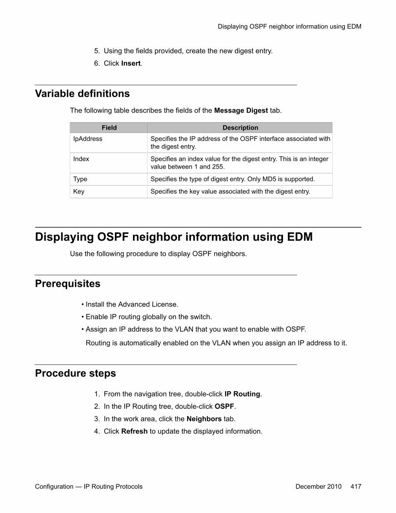
5. Using the fields provided, create the new digest entry.
6. Click Insert.
Variable definitionsThe following table describes the fields of the Message Digest tab.
Field DescriptionIpAddress Specifies the IP address of the OSPF interface associated with
the digest entry.
Index Specifies an index value for the digest entry. This is an integervalue between 1 and 255.
Type Specifies the type of digest entry. Only MD5 is supported.
Key Specifies the key value associated with the digest entry.
Displaying OSPF neighbor information using EDMUse the following procedure to display OSPF neighbors.
Prerequisites
• Install the Advanced License.
• Enable IP routing globally on the switch.
• Assign an IP address to the VLAN that you want to enable with OSPF.
Routing is automatically enabled on the VLAN when you assign an IP address to it.
Procedure steps
1. From the navigation tree, double-click IP Routing.
2. In the IP Routing tree, double-click OSPF.
3. In the work area, click the Neighbors tab.
4. Click Refresh to update the displayed information.
Displaying OSPF neighbor information using EDM
Configuration — IP Routing Protocols December 2010 417
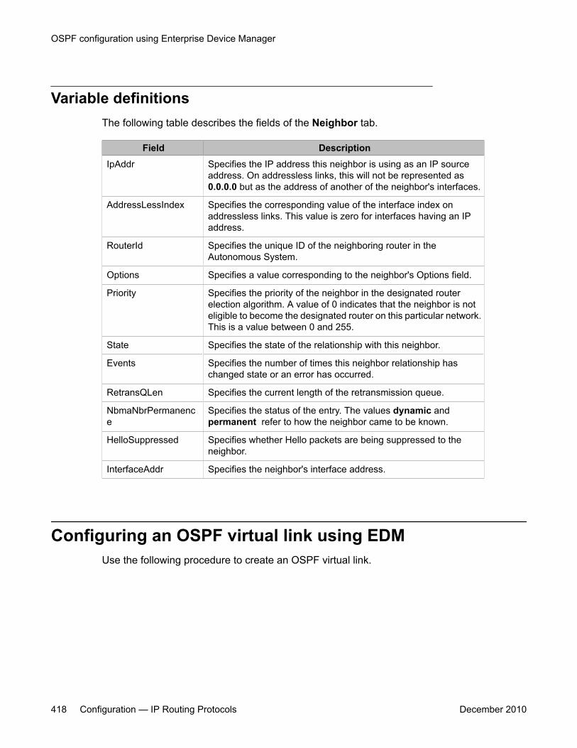
Variable definitionsThe following table describes the fields of the Neighbor tab.
Field DescriptionIpAddr Specifies the IP address this neighbor is using as an IP source
address. On addressless links, this will not be represented as0.0.0.0 but as the address of another of the neighbor's interfaces.
AddressLessIndex Specifies the corresponding value of the interface index onaddressless links. This value is zero for interfaces having an IPaddress.
RouterId Specifies the unique ID of the neighboring router in theAutonomous System.
Options Specifies a value corresponding to the neighbor's Options field.
Priority Specifies the priority of the neighbor in the designated routerelection algorithm. A value of 0 indicates that the neighbor is noteligible to become the designated router on this particular network.This is a value between 0 and 255.
State Specifies the state of the relationship with this neighbor.
Events Specifies the number of times this neighbor relationship haschanged state or an error has occurred.
RetransQLen Specifies the current length of the retransmission queue.
NbmaNbrPermanence
Specifies the status of the entry. The values dynamic andpermanent refer to how the neighbor came to be known.
HelloSuppressed Specifies whether Hello packets are being suppressed to theneighbor.
InterfaceAddr Specifies the neighbor's interface address.
Configuring an OSPF virtual link using EDMUse the following procedure to create an OSPF virtual link.
OSPF configuration using Enterprise Device Manager
418 Configuration — IP Routing Protocols December 2010
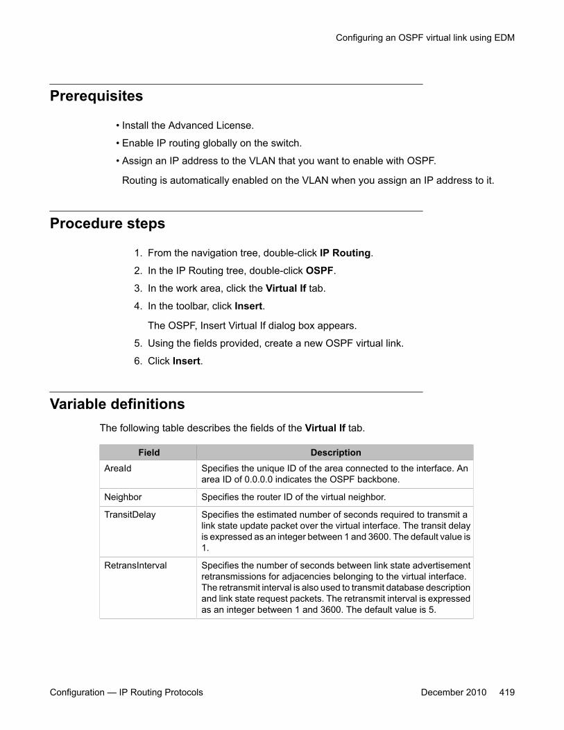
Prerequisites
• Install the Advanced License.
• Enable IP routing globally on the switch.
• Assign an IP address to the VLAN that you want to enable with OSPF.
Routing is automatically enabled on the VLAN when you assign an IP address to it.
Procedure steps
1. From the navigation tree, double-click IP Routing.
2. In the IP Routing tree, double-click OSPF.
3. In the work area, click the Virtual If tab.
4. In the toolbar, click Insert.
The OSPF, Insert Virtual If dialog box appears.
5. Using the fields provided, create a new OSPF virtual link.
6. Click Insert.
Variable definitionsThe following table describes the fields of the Virtual If tab.
Field DescriptionAreaId Specifies the unique ID of the area connected to the interface. An
area ID of 0.0.0.0 indicates the OSPF backbone.
Neighbor Specifies the router ID of the virtual neighbor.
TransitDelay Specifies the estimated number of seconds required to transmit alink state update packet over the virtual interface. The transit delayis expressed as an integer between 1 and 3600. The default value is1.
RetransInterval Specifies the number of seconds between link state advertisementretransmissions for adjacencies belonging to the virtual interface.The retransmit interval is also used to transmit database descriptionand link state request packets. The retransmit interval is expressedas an integer between 1 and 3600. The default value is 5.
Configuring an OSPF virtual link using EDM
Configuration — IP Routing Protocols December 2010 419
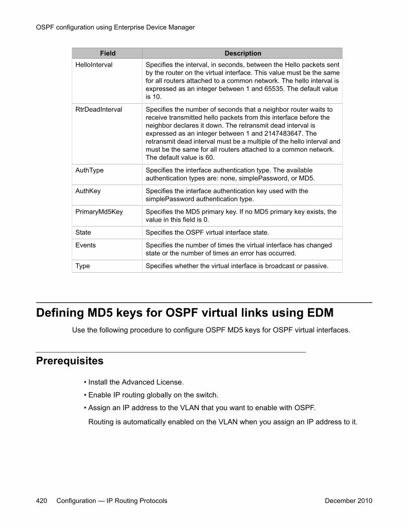
Field DescriptionHelloInterval Specifies the interval, in seconds, between the Hello packets sent
by the router on the virtual interface. This value must be the samefor all routers attached to a common network. The hello interval isexpressed as an integer between 1 and 65535. The default valueis 10.
RtrDeadInterval Specifies the number of seconds that a neighbor router waits toreceive transmitted hello packets from this interface before theneighbor declares it down. The retransmit dead interval isexpressed as an integer between 1 and 2147483647. Theretransmit dead interval must be a multiple of the hello interval andmust be the same for all routers attached to a common network.The default value is 60.
AuthType Specifies the interface authentication type. The availableauthentication types are: none, simplePassword, or MD5.
AuthKey Specifies the interface authentication key used with thesimplePassword authentication type.
PrimaryMd5Key Specifies the MD5 primary key. If no MD5 primary key exists, thevalue in this field is 0.
State Specifies the OSPF virtual interface state.
Events Specifies the number of times the virtual interface has changedstate or the number of times an error has occurred.
Type Specifies whether the virtual interface is broadcast or passive.
Defining MD5 keys for OSPF virtual links using EDMUse the following procedure to configure OSPF MD5 keys for OSPF virtual interfaces.
Prerequisites
• Install the Advanced License.
• Enable IP routing globally on the switch.
• Assign an IP address to the VLAN that you want to enable with OSPF.
Routing is automatically enabled on the VLAN when you assign an IP address to it.
OSPF configuration using Enterprise Device Manager
420 Configuration — IP Routing Protocols December 2010
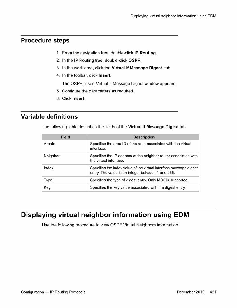
Procedure steps
1. From the navigation tree, double-click IP Routing.
2. In the IP Routing tree, double-click OSPF.
3. In the work area, click the Virtual If Message Digest tab.
4. In the toolbar, click Insert.
The OSPF, Insert Virtual If Message Digest window appears.
5. Configure the parameters as required.
6. Click Insert.
Variable definitionsThe following table describes the fields of the Virtual If Message Digest tab.
Field DescriptionAreaId Specifies the area ID of the area associated with the virtual
interface.
Neighbor Specifies the IP address of the neighbor router associated withthe virtual interface.
Index Specifies the index value of the virtual interface message digestentry. The value is an integer between 1 and 255.
Type Specifies the type of digest entry. Only MD5 is supported.
Key Specifies the key value associated with the digest entry.
Displaying virtual neighbor information using EDMUse the following procedure to view OSPF Virtual Neighbors information.
Displaying virtual neighbor information using EDM
Configuration — IP Routing Protocols December 2010 421

Prerequisites
• Install the Advanced License.
• Enable IP routing globally on the switch.
• Assign an IP address to the VLAN that you want to enable with OSPF.
Routing is automatically enabled on the VLAN when you assign an IP address to it.
Procedure steps
1. From the navigation tree, double-click IP Routing.
2. In the IP Routing tree, double-click OSPF.
3. In the work area, click the Virtual Neighbors tab.
4. Click Refresh to update the displayed information.
Variable definitionsThe following table describes the fields of the Virtual Neighbors tab.
Field DescriptionArea Specifies the subnetwork in which the virtual neighbor resides.
RouterId Specifies the 32-bit integer uniquely identifying the neighboringrouter in the autonomous system.
IpAddr Specifies the IP address of the virtual neighboring router.
Options Specifies a bit mask corresponding to the option field of theneighbor.
State Specifies the state of the virtual neighbor relationship.
Events Specifies the number of state changes or error events that haveoccurred between the OSPF router and the neighbor router.
RetransQLen Specifies the current length of the retransmission queue (thenumber of elapsed seconds between advertising retransmissionsof the same packet to a neighbor).
HelloSuppressed Specifies whether Hello packets to the virtual neighbor aresuppressed or not.
OSPF configuration using Enterprise Device Manager
422 Configuration — IP Routing Protocols December 2010
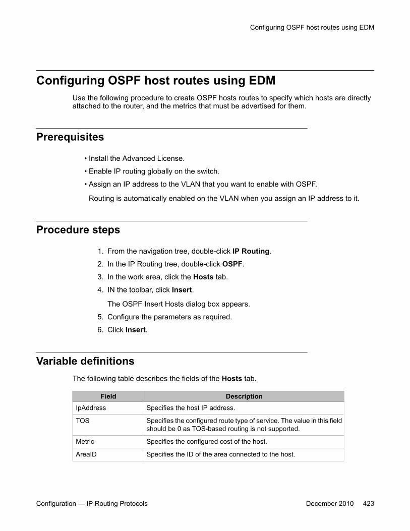
Configuring OSPF host routes using EDMUse the following procedure to create OSPF hosts routes to specify which hosts are directlyattached to the router, and the metrics that must be advertised for them.
Prerequisites
• Install the Advanced License.
• Enable IP routing globally on the switch.
• Assign an IP address to the VLAN that you want to enable with OSPF.
Routing is automatically enabled on the VLAN when you assign an IP address to it.
Procedure steps
1. From the navigation tree, double-click IP Routing.
2. In the IP Routing tree, double-click OSPF.
3. In the work area, click the Hosts tab.
4. IN the toolbar, click Insert.
The OSPF Insert Hosts dialog box appears.
5. Configure the parameters as required.
6. Click Insert.
Variable definitionsThe following table describes the fields of the Hosts tab.
Field DescriptionIpAddress Specifies the host IP address.
TOS Specifies the configured route type of service. The value in this fieldshould be 0 as TOS-based routing is not supported.
Metric Specifies the configured cost of the host.
AreaID Specifies the ID of the area connected to the host.
Configuring OSPF host routes using EDM
Configuration — IP Routing Protocols December 2010 423
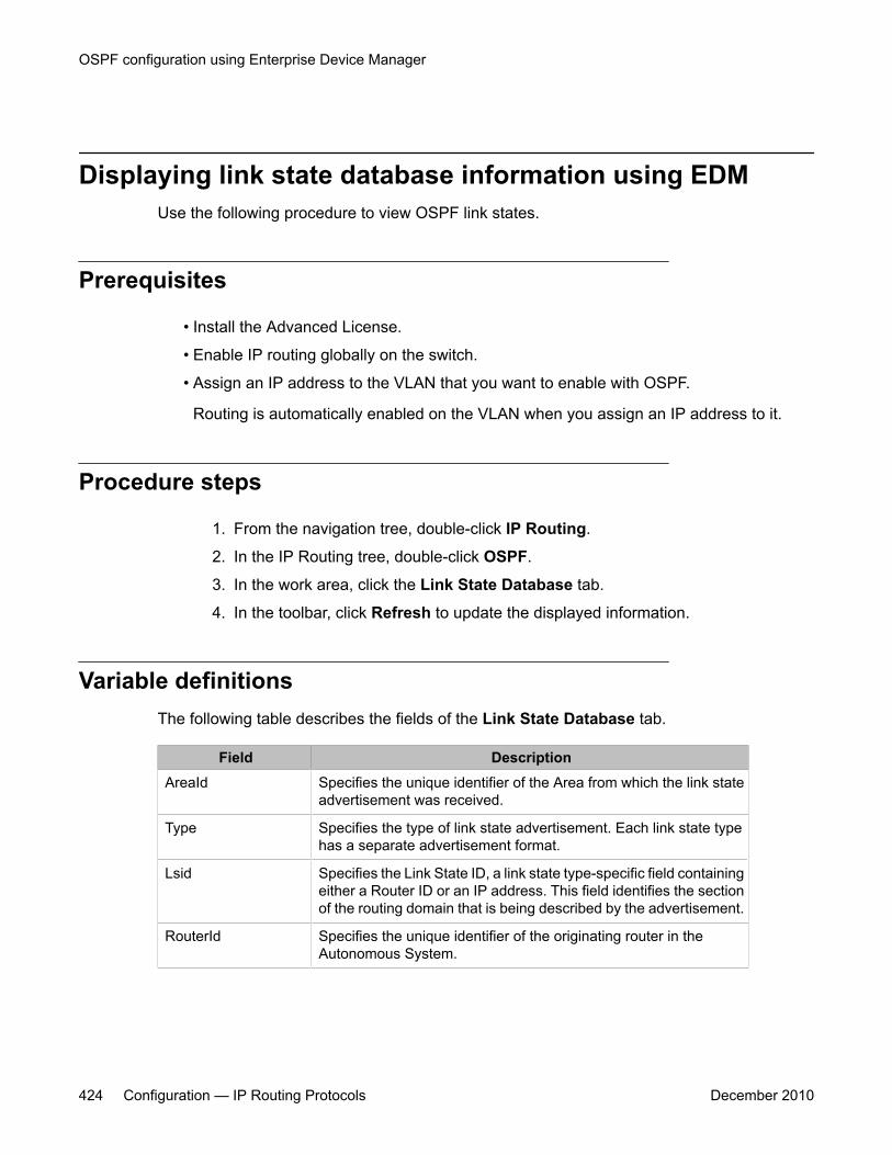
Displaying link state database information using EDMUse the following procedure to view OSPF link states.
Prerequisites
• Install the Advanced License.
• Enable IP routing globally on the switch.
• Assign an IP address to the VLAN that you want to enable with OSPF.
Routing is automatically enabled on the VLAN when you assign an IP address to it.
Procedure steps
1. From the navigation tree, double-click IP Routing.
2. In the IP Routing tree, double-click OSPF.
3. In the work area, click the Link State Database tab.
4. In the toolbar, click Refresh to update the displayed information.
Variable definitionsThe following table describes the fields of the Link State Database tab.
Field DescriptionAreaId Specifies the unique identifier of the Area from which the link state
advertisement was received.
Type Specifies the type of link state advertisement. Each link state typehas a separate advertisement format.
Lsid Specifies the Link State ID, a link state type-specific field containingeither a Router ID or an IP address. This field identifies the sectionof the routing domain that is being described by the advertisement.
RouterId Specifies the unique identifier of the originating router in theAutonomous System.
OSPF configuration using Enterprise Device Manager
424 Configuration — IP Routing Protocols December 2010

Field DescriptionSequence Detects old or duplicate link state advertisements by assigning an
incremental number to duplicate advertisements. The higher thesequence number, the more recent the advertisement.
Age Specifies the age of the link state advertisement in seconds.
Checksum Specifies the checksum of the complete content of theadvertisement, excluding the Age field. This field is excluded so thatthe advertisement's age can be increased without updating thechecksum. The checksum used is the same as that used in ISOconnectionless datagrams and is commonly referred to as theFletcher checksum.
Displaying external link state database information usingEDM
Use the following procedure to view the OSPF external link state database.
Prerequisites
• Install the Advanced License.
• Enable IP routing globally on the switch.
• Assign an IP address to the VLAN that you want to enable with OSPF.
Routing is automatically enabled on the VLAN when you assign an IP address to it.
Procedure steps
1. From the navigation tree, double-click IP Routing.
2. In the IP Routing tree, double-click OSPF.
3. In the work area, click the Ext. Link State Database tab.
4. In the toolbar, click Refresh to update the displayed information.
Variable definitionsThe following table describes the fields of the Ext. Link State Database tab.
Displaying external link state database information using EDM
Configuration — IP Routing Protocols December 2010 425
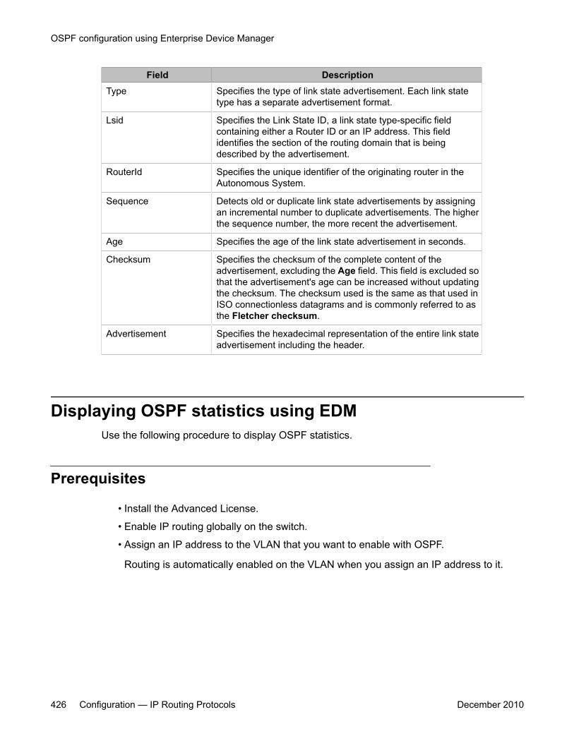
Field DescriptionType Specifies the type of link state advertisement. Each link state
type has a separate advertisement format.
Lsid Specifies the Link State ID, a link state type-specific fieldcontaining either a Router ID or an IP address. This fieldidentifies the section of the routing domain that is beingdescribed by the advertisement.
RouterId Specifies the unique identifier of the originating router in theAutonomous System.
Sequence Detects old or duplicate link state advertisements by assigningan incremental number to duplicate advertisements. The higherthe sequence number, the more recent the advertisement.
Age Specifies the age of the link state advertisement in seconds.
Checksum Specifies the checksum of the complete content of theadvertisement, excluding the Age field. This field is excluded sothat the advertisement's age can be increased without updatingthe checksum. The checksum used is the same as that used inISO connectionless datagrams and is commonly referred to asthe Fletcher checksum.
Advertisement Specifies the hexadecimal representation of the entire link stateadvertisement including the header.
Displaying OSPF statistics using EDMUse the following procedure to display OSPF statistics.
Prerequisites
• Install the Advanced License.
• Enable IP routing globally on the switch.
• Assign an IP address to the VLAN that you want to enable with OSPF.
Routing is automatically enabled on the VLAN when you assign an IP address to it.
OSPF configuration using Enterprise Device Manager
426 Configuration — IP Routing Protocols December 2010
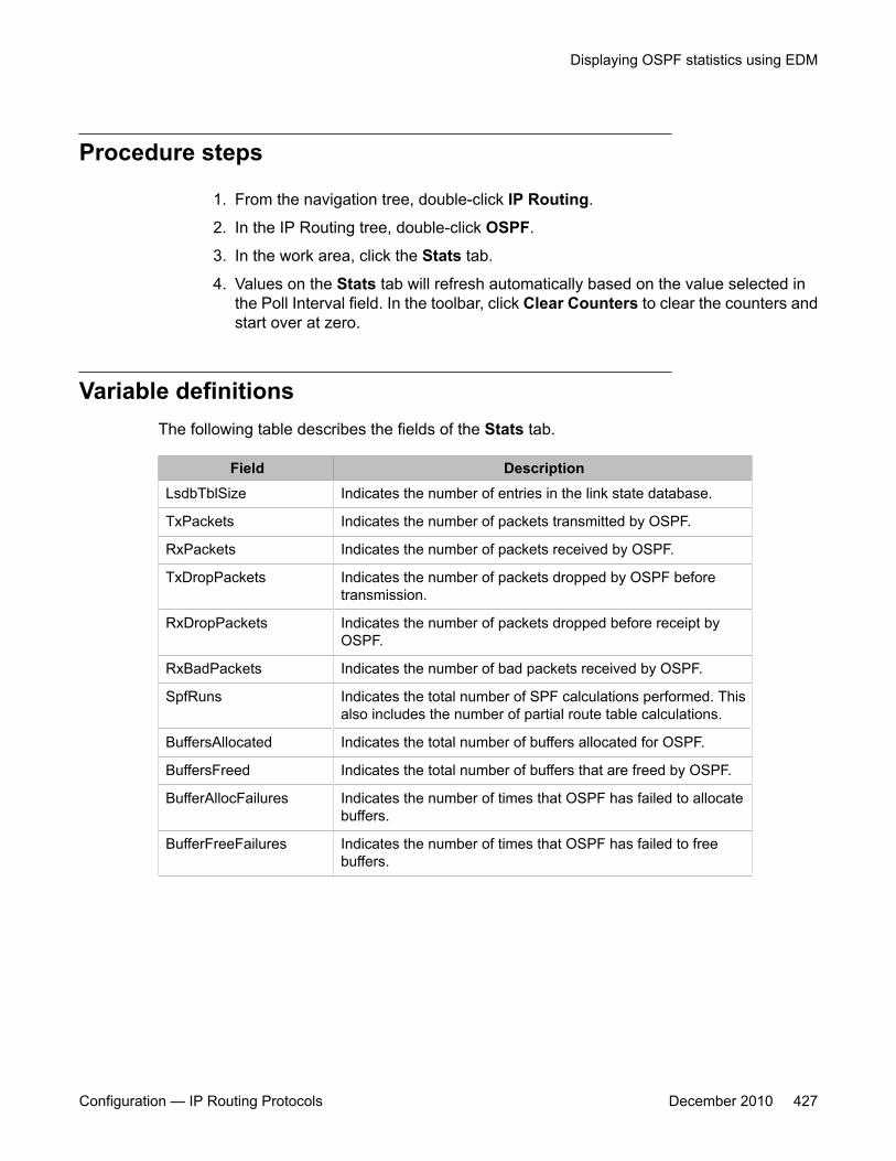
Procedure steps
1. From the navigation tree, double-click IP Routing.
2. In the IP Routing tree, double-click OSPF.
3. In the work area, click the Stats tab.
4. Values on the Stats tab will refresh automatically based on the value selected inthe Poll Interval field. In the toolbar, click Clear Counters to clear the counters andstart over at zero.
Variable definitionsThe following table describes the fields of the Stats tab.
Field DescriptionLsdbTblSize Indicates the number of entries in the link state database.
TxPackets Indicates the number of packets transmitted by OSPF.
RxPackets Indicates the number of packets received by OSPF.
TxDropPackets Indicates the number of packets dropped by OSPF beforetransmission.
RxDropPackets Indicates the number of packets dropped before receipt byOSPF.
RxBadPackets Indicates the number of bad packets received by OSPF.
SpfRuns Indicates the total number of SPF calculations performed. Thisalso includes the number of partial route table calculations.
BuffersAllocated Indicates the total number of buffers allocated for OSPF.
BuffersFreed Indicates the total number of buffers that are freed by OSPF.
BufferAllocFailures Indicates the number of times that OSPF has failed to allocatebuffers.
BufferFreeFailures Indicates the number of times that OSPF has failed to freebuffers.
Displaying OSPF statistics using EDM
Configuration — IP Routing Protocols December 2010 427
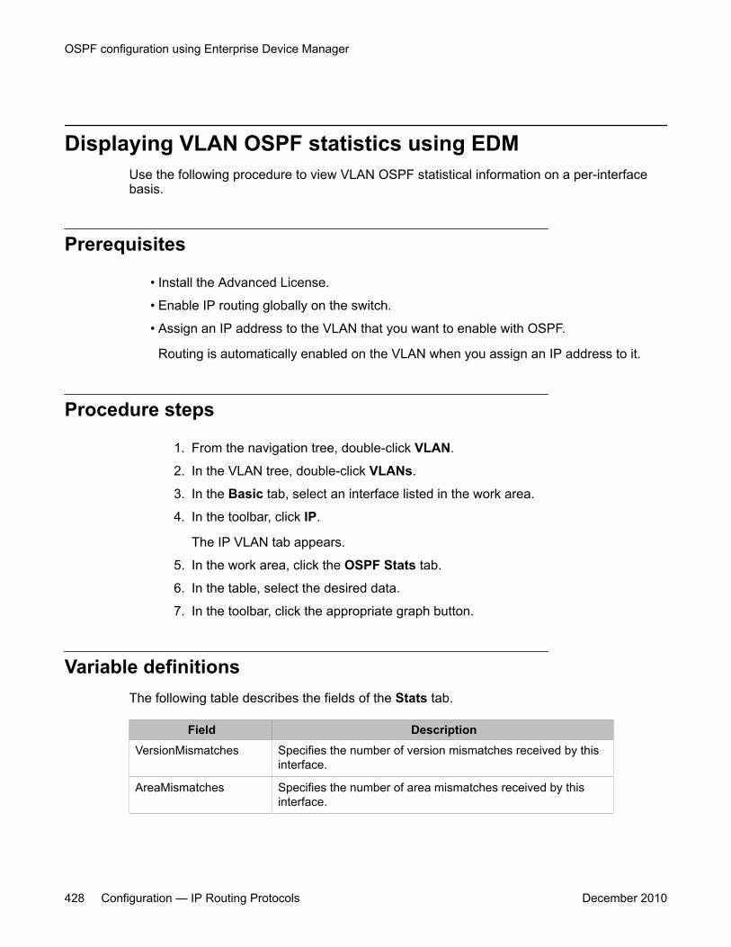
Displaying VLAN OSPF statistics using EDMUse the following procedure to view VLAN OSPF statistical information on a per-interfacebasis.
Prerequisites
• Install the Advanced License.
• Enable IP routing globally on the switch.
• Assign an IP address to the VLAN that you want to enable with OSPF.
Routing is automatically enabled on the VLAN when you assign an IP address to it.
Procedure steps
1. From the navigation tree, double-click VLAN.
2. In the VLAN tree, double-click VLANs.
3. In the Basic tab, select an interface listed in the work area.
4. In the toolbar, click IP.
The IP VLAN tab appears.
5. In the work area, click the OSPF Stats tab.
6. In the table, select the desired data.
7. In the toolbar, click the appropriate graph button.
Variable definitionsThe following table describes the fields of the Stats tab.
Field DescriptionVersionMismatches Specifies the number of version mismatches received by this
interface.
AreaMismatches Specifies the number of area mismatches received by thisinterface.
OSPF configuration using Enterprise Device Manager
428 Configuration — IP Routing Protocols December 2010
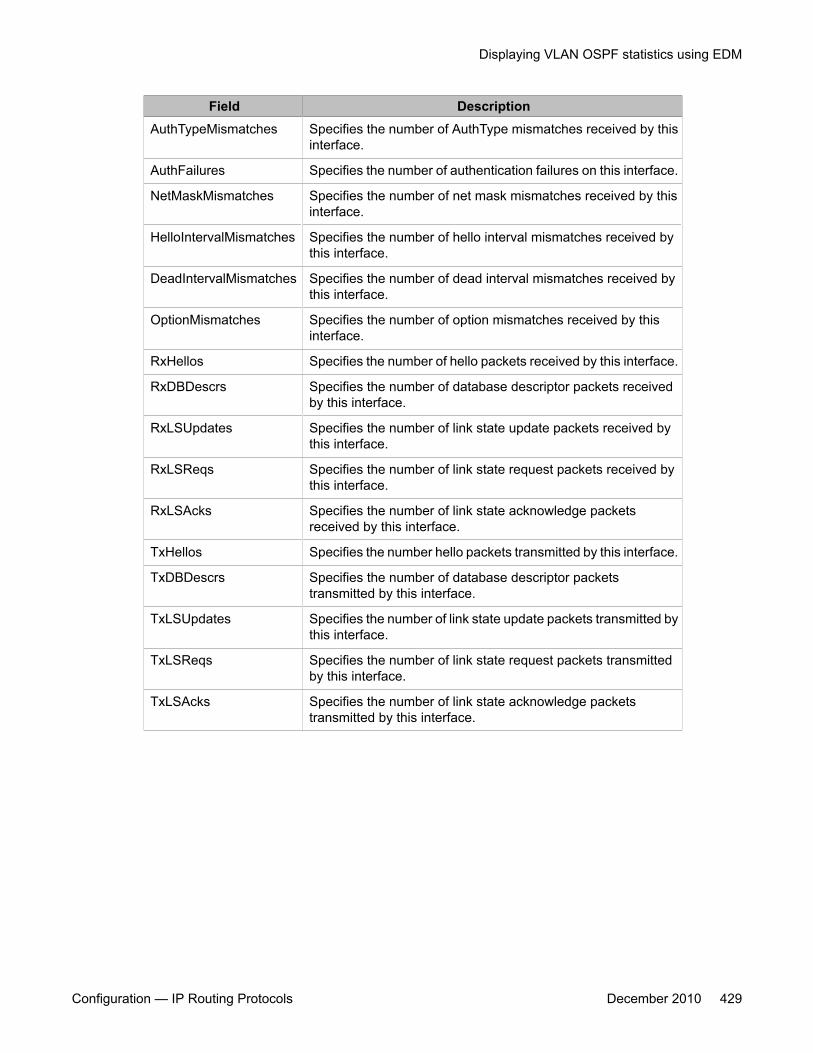
Field DescriptionAuthTypeMismatches Specifies the number of AuthType mismatches received by this
interface.
AuthFailures Specifies the number of authentication failures on this interface.
NetMaskMismatches Specifies the number of net mask mismatches received by thisinterface.
HelloIntervalMismatches Specifies the number of hello interval mismatches received bythis interface.
DeadIntervalMismatches Specifies the number of dead interval mismatches received bythis interface.
OptionMismatches Specifies the number of option mismatches received by thisinterface.
RxHellos Specifies the number of hello packets received by this interface.
RxDBDescrs Specifies the number of database descriptor packets receivedby this interface.
RxLSUpdates Specifies the number of link state update packets received bythis interface.
RxLSReqs Specifies the number of link state request packets received bythis interface.
RxLSAcks Specifies the number of link state acknowledge packetsreceived by this interface.
TxHellos Specifies the number hello packets transmitted by this interface.
TxDBDescrs Specifies the number of database descriptor packetstransmitted by this interface.
TxLSUpdates Specifies the number of link state update packets transmitted bythis interface.
TxLSReqs Specifies the number of link state request packets transmittedby this interface.
TxLSAcks Specifies the number of link state acknowledge packetstransmitted by this interface.
Displaying VLAN OSPF statistics using EDM
Configuration — IP Routing Protocols December 2010 429

OSPF configuration using Enterprise Device Manager
430 Configuration — IP Routing Protocols December 2010
Chapter 32: RIP configuration usingEnterprise Device Manager
This chapter describes the procedure you can use to configure and manage the Routing InformationProtocol (RIP) on the Avaya Ethernet Routing Switch 5000 Series . RIP is a distance vector protocol usedto dynamically discover network routes based on information passed between routers in the network. RIPis useful in network environments where using static route administration would be difficult.
Prerequisites• Enable IP routing globally.
• Assign an IP address to the VLAN or brouter port that you want to enable with RIP.
Routing is automatically enabled on the VLAN when you assign an IP address to it.
Configuring RIP using EDMUse the following procedure to configure RIP routing on the Ethernet Routing Switch.
Procedure steps
1. Enable RIP globally.
2. Configure global RIP properties as required.
3. Enable RIP on the desired VLAN or brouter interfaces.
4. Configure interface RIP properties as required.
Navigation
• Configuring Global RIP properties using EDM on page 432
• Configuring a RIP interface using EDM on page 433
Configuration — IP Routing Protocols December 2010 431
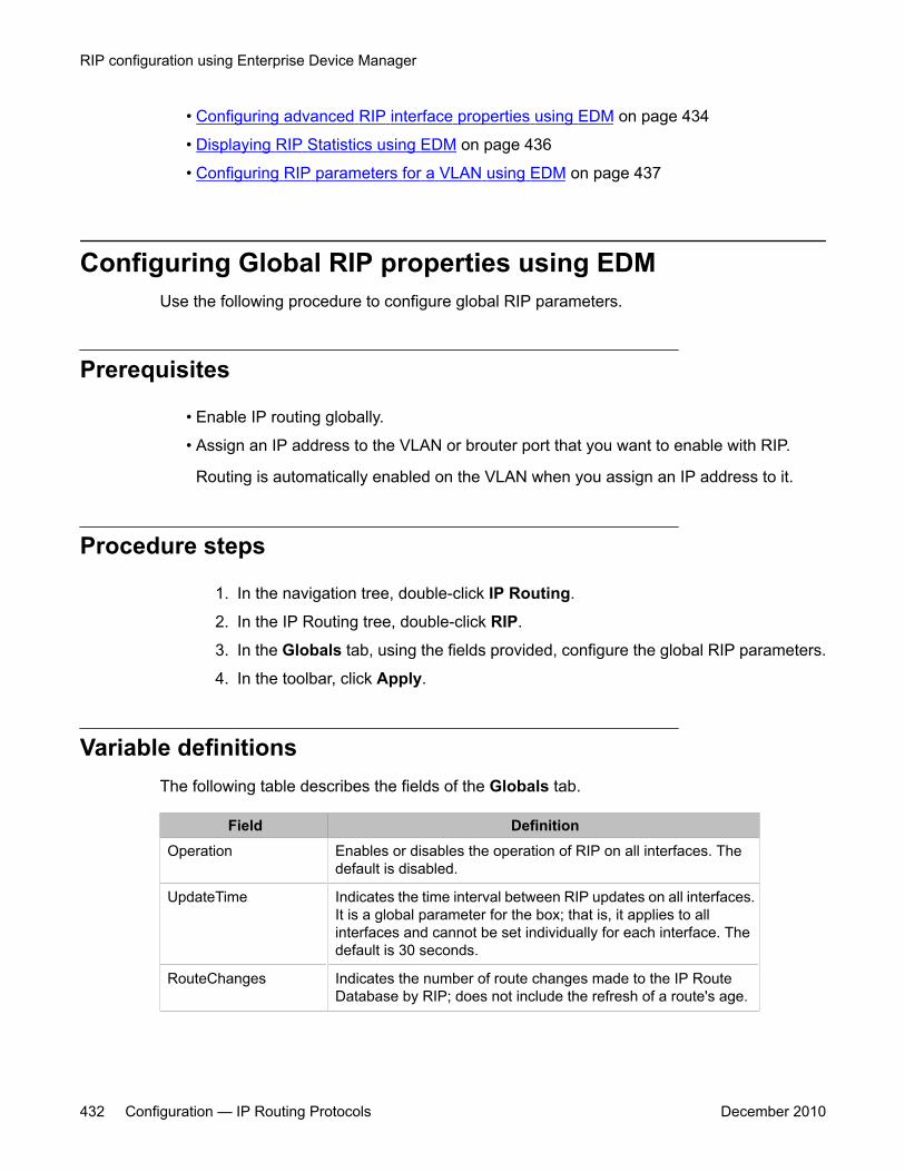
• Configuring advanced RIP interface properties using EDM on page 434
• Displaying RIP Statistics using EDM on page 436
• Configuring RIP parameters for a VLAN using EDM on page 437
Configuring Global RIP properties using EDMUse the following procedure to configure global RIP parameters.
Prerequisites
• Enable IP routing globally.
• Assign an IP address to the VLAN or brouter port that you want to enable with RIP.
Routing is automatically enabled on the VLAN when you assign an IP address to it.
Procedure steps
1. In the navigation tree, double-click IP Routing.
2. In the IP Routing tree, double-click RIP.
3. In the Globals tab, using the fields provided, configure the global RIP parameters.
4. In the toolbar, click Apply.
Variable definitionsThe following table describes the fields of the Globals tab.
Field DefinitionOperation Enables or disables the operation of RIP on all interfaces. The
default is disabled.
UpdateTime Indicates the time interval between RIP updates on all interfaces.It is a global parameter for the box; that is, it applies to allinterfaces and cannot be set individually for each interface. Thedefault is 30 seconds.
RouteChanges Indicates the number of route changes made to the IP RouteDatabase by RIP; does not include the refresh of a route's age.
RIP configuration using Enterprise Device Manager
432 Configuration — IP Routing Protocols December 2010
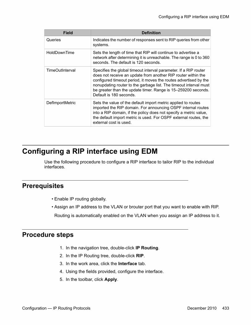
Field DefinitionQueries Indicates the number of responses sent to RIP queries from other
systems.
HoldDownTime Sets the length of time that RIP will continue to advertise anetwork after determining it is unreachable. The range is 0 to 360seconds. The default is 120 seconds.
TimeOutInterval Specifies the global timeout interval parameter. If a RIP routerdoes not receive an update from another RIP router within theconfigured timeout period, it moves the routes advertised by thenonupdating router to the garbage list. The timeout interval mustbe greater than the update timer. Range is 15–259200 seconds.Default is 180 seconds.
DefImportMetric Sets the value of the default import metric applied to routesimported the RIP domain. For announcing OSPF internal routesinto a RIP domain, if the policy does not specify a metric value,the default import metric is used. For OSPF external routes, theexternal cost is used.
Configuring a RIP interface using EDMUse the following procedure to configure a RIP interface to tailor RIP to the individualinterfaces.
Prerequisites
• Enable IP routing globally.
• Assign an IP address to the VLAN or brouter port that you want to enable with RIP.
Routing is automatically enabled on the VLAN when you assign an IP address to it.
Procedure steps
1. In the navigation tree, double-click IP Routing.
2. In the IP Routing tree, double-click RIP.
3. In the work area, click the Interface tab.
4. Using the fields provided, configure the interface.
5. In the toolbar, click Apply.
Configuring a RIP interface using EDM
Configuration — IP Routing Protocols December 2010 433
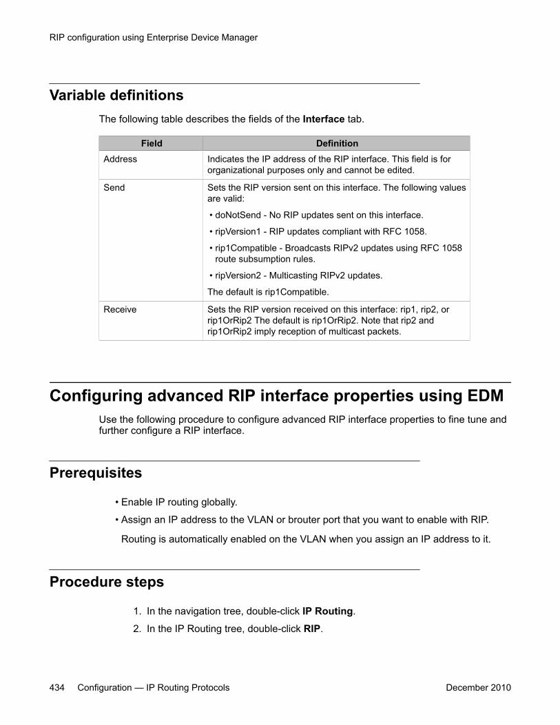
Variable definitionsThe following table describes the fields of the Interface tab.
Field DefinitionAddress Indicates the IP address of the RIP interface. This field is for
organizational purposes only and cannot be edited.
Send Sets the RIP version sent on this interface. The following valuesare valid:
• doNotSend - No RIP updates sent on this interface.
• ripVersion1 - RIP updates compliant with RFC 1058.
• rip1Compatible - Broadcasts RIPv2 updates using RFC 1058route subsumption rules.
• ripVersion2 - Multicasting RIPv2 updates.
The default is rip1Compatible.
Receive Sets the RIP version received on this interface: rip1, rip2, orrip1OrRip2 The default is rip1OrRip2. Note that rip2 andrip1OrRip2 imply reception of multicast packets.
Configuring advanced RIP interface properties using EDMUse the following procedure to configure advanced RIP interface properties to fine tune andfurther configure a RIP interface.
Prerequisites
• Enable IP routing globally.
• Assign an IP address to the VLAN or brouter port that you want to enable with RIP.
Routing is automatically enabled on the VLAN when you assign an IP address to it.
Procedure steps
1. In the navigation tree, double-click IP Routing.
2. In the IP Routing tree, double-click RIP.
RIP configuration using Enterprise Device Manager
434 Configuration — IP Routing Protocols December 2010

3. In the work area, click the Interface Advance tab.
4. Using the fields provided, configure the advanced RIP features.
5. In the toolbar, click Apply.
Variable definitionsThe following table describes the fields of the Interface Advance tab.
Field DefinitionAddress Indicates the IP address of the RIP interface. This field is for
organizational purposes only and cannot be edited.
Interface Indicates the switch interface that corresponds to the listed IPaddress.
Enable Enables or disables RIP on this interface.
Supply Determines whether this interface supplies RIP advertisements.
Listen Determines whether this interface listens for RIP advertisements.
Poison Enables or disables poison reverse on this interface.
DefaultSupply Determines whether this interface advertises default routes.
DefaultListen Determines whether this interface listens for default routeradvertisements.
TriggeredUpdate Enables or disables triggered updates on this interface.
AutoAggregate Enables or disables auto aggregation on this interface.
InPolicy Associates a previously configured switch policy with thisinterface for use as an in policy.
OutPolicy Associates a previously configured switch policy with thisinterface for use as an out policy.
Cost Indicates the cost associated with this interface.
HoldDownTime Sets the holddown timer for this interface. This is an integer valuein seconds between 0 and 360.
TimeoutInterval Sets the timeout interval for this interface. This is an integer valuebetween 15 and 259200.
ProxyAnnounceFlag Enables or disables proxy announcements on this interface.
Configuring advanced RIP interface properties using EDM
Configuration — IP Routing Protocols December 2010 435
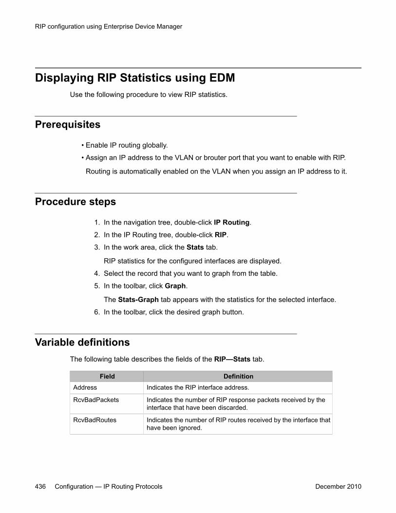
Displaying RIP Statistics using EDMUse the following procedure to view RIP statistics.
Prerequisites
• Enable IP routing globally.
• Assign an IP address to the VLAN or brouter port that you want to enable with RIP.
Routing is automatically enabled on the VLAN when you assign an IP address to it.
Procedure steps
1. In the navigation tree, double-click IP Routing.
2. In the IP Routing tree, double-click RIP.
3. In the work area, click the Stats tab.
RIP statistics for the configured interfaces are displayed.
4. Select the record that you want to graph from the table.
5. In the toolbar, click Graph.
The Stats-Graph tab appears with the statistics for the selected interface.
6. In the toolbar, click the desired graph button.
Variable definitionsThe following table describes the fields of the RIP—Stats tab.
Field DefinitionAddress Indicates the RIP interface address.
RcvBadPackets Indicates the number of RIP response packets received by theinterface that have been discarded.
RcvBadRoutes Indicates the number of RIP routes received by the interface thathave been ignored.
RIP configuration using Enterprise Device Manager
436 Configuration — IP Routing Protocols December 2010
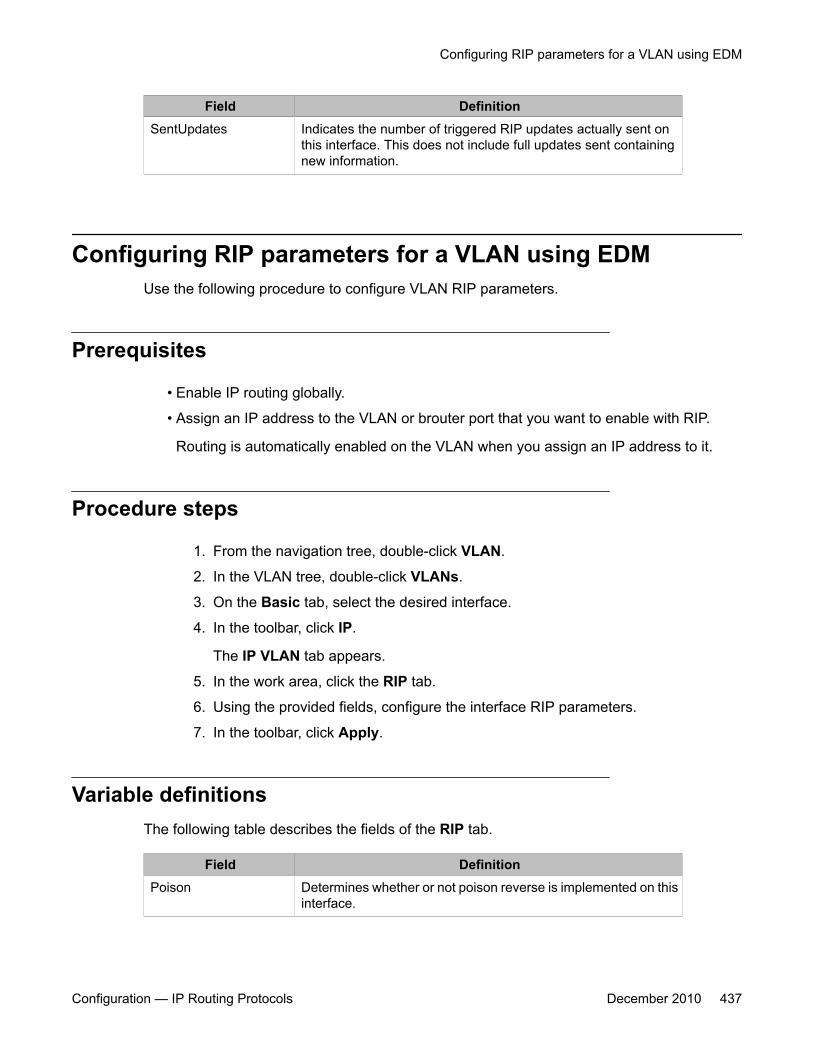
Field DefinitionSentUpdates Indicates the number of triggered RIP updates actually sent on
this interface. This does not include full updates sent containingnew information.
Configuring RIP parameters for a VLAN using EDMUse the following procedure to configure VLAN RIP parameters.
Prerequisites
• Enable IP routing globally.
• Assign an IP address to the VLAN or brouter port that you want to enable with RIP.
Routing is automatically enabled on the VLAN when you assign an IP address to it.
Procedure steps
1. From the navigation tree, double-click VLAN.
2. In the VLAN tree, double-click VLANs.
3. On the Basic tab, select the desired interface.
4. In the toolbar, click IP.
The IP VLAN tab appears.
5. In the work area, click the RIP tab.
6. Using the provided fields, configure the interface RIP parameters.
7. In the toolbar, click Apply.
Variable definitionsThe following table describes the fields of the RIP tab.
Field DefinitionPoison Determines whether or not poison reverse is implemented on this
interface.
Configuring RIP parameters for a VLAN using EDM
Configuration — IP Routing Protocols December 2010 437
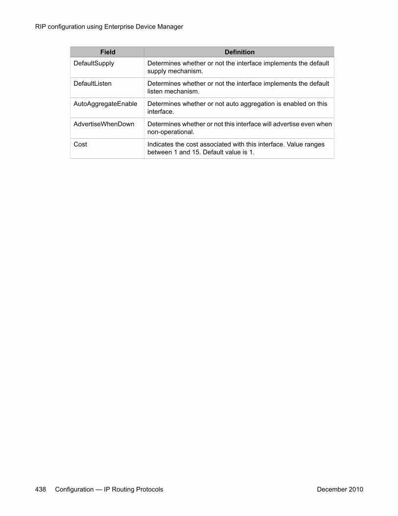
Field DefinitionDefaultSupply Determines whether or not the interface implements the default
supply mechanism.
DefaultListen Determines whether or not the interface implements the defaultlisten mechanism.
AutoAggregateEnable Determines whether or not auto aggregation is enabled on thisinterface.
AdvertiseWhenDown Determines whether or not this interface will advertise even whennon-operational.
Cost Indicates the cost associated with this interface. Value rangesbetween 1 and 15. Default value is 1.
RIP configuration using Enterprise Device Manager
438 Configuration — IP Routing Protocols December 2010
Chapter 33: ECMP configuration usingEnterprise Device Manager
This chapter describes the procedure you can use to configure ECMP using Enterprise Device Manager(EDM).
The Equal Cost MultiPath (ECMP) feature allows routers to determine equal cost paths to the samedestination prefix. The multiple paths can be used for load sharing of traffic and allows faster convergenceto other active paths in case of network failure.
Important:ECMP is not supported on the Avaya Ethernet Routing Switch 5510. ECMP works in a mixed stack butcannot run on any Avaya Ethernet Routing Switch 5510 units in the stack.
Prerequisites• Install the Advanced License.
• Enable IP routing globally on the switch.
• Configure routing (RIP, OSPF, or static routes) on the switch.
Configuring ECMP using EDMUse the following procedure to configure and ECMP settings for RIP, OSPF, and static routes.
Prerequisites
• Install the Advanced License.
• Enable IP routing globally on the switch.
• Configure routing (RIP, OSPF, or static routes) on the switch.
Configuration — IP Routing Protocols December 2010 439

Procedure steps
1. From the navigation tree, double-click IP Routing.
2. In the IP Routing tree, double-click IP.
3. In the work area, click the ECMP tab.
4. In the table, double-click the cell under the MaxPath column heading for theparameter you want to change.
5. Select a parameter or value from the drop-down list.
6. Repeat the previous two steps until you have amended all of the parameters youwant to change.
7. In the toolbar, click Apply.
Variable definitionsThe following table describes the fields of the ECMP tab.
Field DescriptionRoutingProtocol Indicates the routing protocol to be configured.
MaxPath Indicates the maximum number of ECMP paths assigned to theprotocol. Value ranges between 1 and 4. Default is 1.
ECMP configuration using Enterprise Device Manager
440 Configuration — IP Routing Protocols December 2010
Chapter 34: Route policies configurationusing Enterprise DeviceManager
This chapter describes the procedure you can use to configure route policies using Enterprise DeviceManager (EDM).
Route policies are an Avaya proprietary improvement on existing routing schemes. Using existing routingschemes, packets are forwarded based on routes that have been learned by the router through routingprotocols such as RIP and OSPF or through the introduction of static routes. Route policies introduce theability to forward packets based on rule sets created by the network administrator. These rule sets, orpolicies, are then applied to the learned or static routes.
Prerequisites• Open one of the supported browsers.
• Enter the IP address of the switch to open an EDM session.
Configuring Route policies using EDMUse the following procedure to configure routing policies.
1. Create the appropriate prefix lists.
2. Assign those prefix lists to route policies.
3. Apply the route policies to the appropriate policy type.
Navigation• Creating a prefix list using EDM on page 442
• Creating a route policy using EDM on page 443
Configuration — IP Routing Protocols December 2010 441
• Configuring RIP in and out policies using EDM on page 445
• Configuring an OSPF Accept Policy using EDM on page 446
• Configuring OSPF redistribution parameters using EDM on page 447
• Applying an OSPF accept or redistribution policy using EDM on page 449
• Configuring the global IP forwarding next-hop status on page 450
• Configuring an IP forwarding next-hop policy on page 450
Creating a prefix list using EDMUse the following procedure to create a new prefix list.
Prefix lists are the base item in a routing policy. Prefix lists contain lists of IP addresses withtheir associated masks that support the comparison of ranges of masks.
Prerequisites
• Open one of the supported browsers.
• Enter the IP address of the switch to open an EDM session.
Procedure steps
1. From the navigation tree, double-click IP Routing.
2. In the IP Routing tree, double-click Policy.
3. In the work area, click the Prefix List tab.
4. In the toolbar, click Insert.
The Insert Prefix List dialog box appears.
5. Using the fields provided, create a new prefix list.
6. Click Insert.
Variable definitionsThe following table describes the fields of the Prefix List tab.
Route policies configuration using Enterprise Device Manager
442 Configuration — IP Routing Protocols December 2010
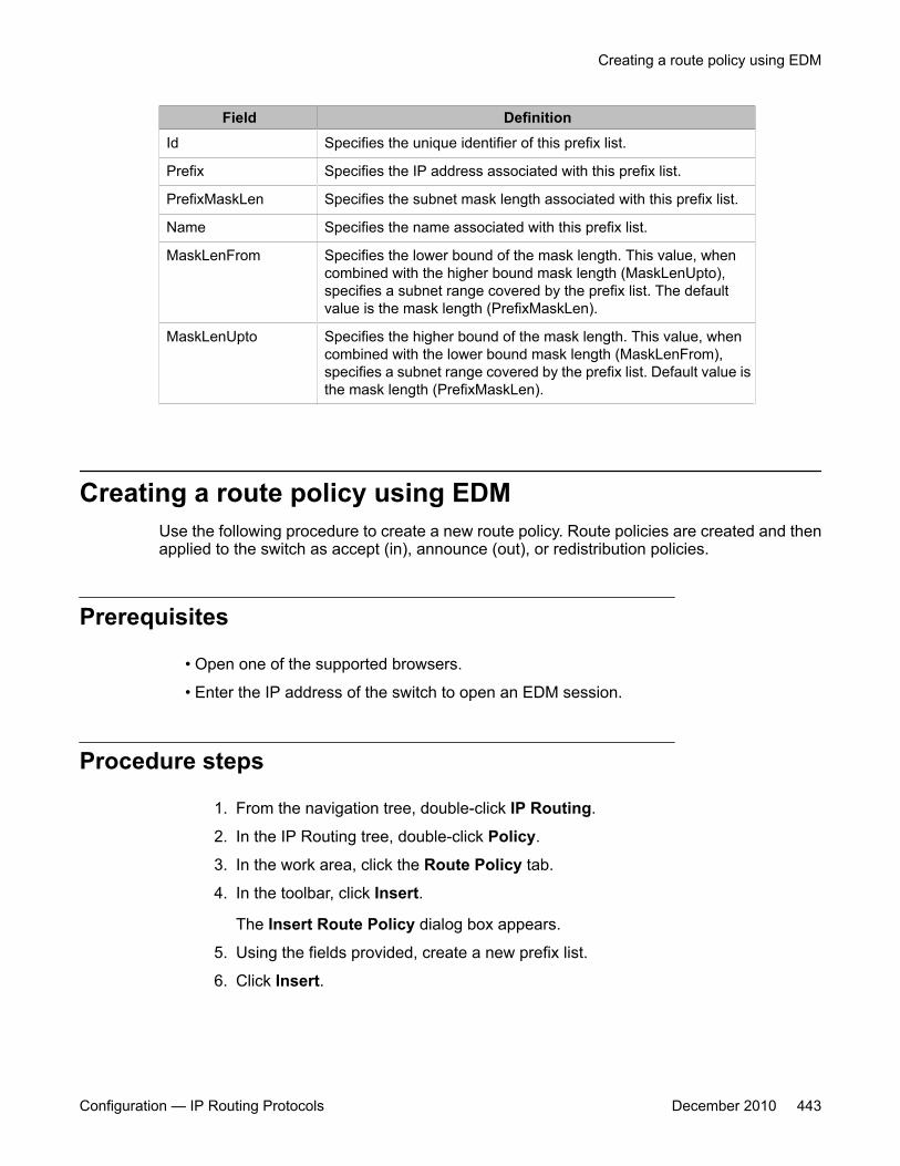
Field DefinitionId Specifies the unique identifier of this prefix list.
Prefix Specifies the IP address associated with this prefix list.
PrefixMaskLen Specifies the subnet mask length associated with this prefix list.
Name Specifies the name associated with this prefix list.
MaskLenFrom Specifies the lower bound of the mask length. This value, whencombined with the higher bound mask length (MaskLenUpto),specifies a subnet range covered by the prefix list. The defaultvalue is the mask length (PrefixMaskLen).
MaskLenUpto Specifies the higher bound of the mask length. This value, whencombined with the lower bound mask length (MaskLenFrom),specifies a subnet range covered by the prefix list. Default value isthe mask length (PrefixMaskLen).
Creating a route policy using EDMUse the following procedure to create a new route policy. Route policies are created and thenapplied to the switch as accept (in), announce (out), or redistribution policies.
Prerequisites
• Open one of the supported browsers.
• Enter the IP address of the switch to open an EDM session.
Procedure steps
1. From the navigation tree, double-click IP Routing.
2. In the IP Routing tree, double-click Policy.
3. In the work area, click the Route Policy tab.
4. In the toolbar, click Insert.
The Insert Route Policy dialog box appears.
5. Using the fields provided, create a new prefix list.
6. Click Insert.
Creating a route policy using EDM
Configuration — IP Routing Protocols December 2010 443

Variable definitionsThe following table describes the fields of the Route Policy tab.
Field DefinitionId Specifies an index value to uniquely identify a policy.
SequenceNumber Specifies a secondary index value that identifies individualpolicies inside a larger policy group.
Name Specifies the name associated with this policy.
Enable Specifies whether this policy sequence number is enabled ordisabled. If disabled, the policy sequence number is ignored.
Mode Specifies the action to be taken when this policy is selected for aspecific route. A value of permit indicates that the route is allowedwhile deny indicates that the route is ignored.
MatchProtocol If configured, matches the protocol through which the route islearned. This field is used only for RIP announce policies. Optionsare RIP, Static, Direct, OSPF or Any.
MatchNetwork If configured, matches the destination network against thecontents of the specified prefix list.
MatchIpRouteSource If configured, matches the source IP address for RIP routes andadvertising router IDs for OSPF routes against the contents of thespecified prefix list. This option is ignored for all other route types.
MatchNextHop If configured, matches the next hop IP address of the routeagainst the contents of the specified prefix list. This field appliesonly to non-local routes.
MatchInterface If configured, matches the IP address of the interface by whichthe RIP route was learned against the contents of the specifiedprefix list. This field is used only for RIP routes and ignored for allother type of route.
MatchRouteType Sets a specific route-type to be matched (applies only to OSPFroutes). Available options are:
• any
• local
• internal
• external
• externaltype1
• externaltype2
Externaltype1and Externaltype2 specify the OSPF routes of thespecified type only.
Route policies configuration using Enterprise Device Manager
444 Configuration — IP Routing Protocols December 2010
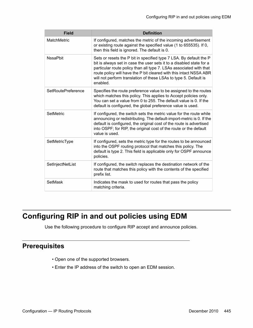
Field DefinitionMatchMetric If configured, matches the metric of the incoming advertisement
or existing route against the specified value (1 to 655535). If 0,then this field is ignored. The default is 0.
NssaPbit Sets or resets the P bit in specified type 7 LSA. By default the Pbit is always set in case the user sets it to a disabled state for aparticular route policy than all type 7. LSAs associated with thatroute policy will have the P bit cleared with this intact NSSA ABRwill not perform translation of these LSAs to type 5. Default isenabled.
SetRoutePreference Specifies the route preference value to be assigned to the routeswhich matches this policy. This applies to Accept policies only.You can set a value from 0 to 255. The default value is 0. If thedefault is configured, the global preference value is used.
SetMetric If configured, the switch sets the metric value for the route whileannouncing or redistributing. The default-import-metric is 0. If thedefault is configured, the original cost of the route is advertisedinto OSPF; for RIP, the original cost of the route or the defaultvalue is used.
SetMetricType If configured, sets the metric type for the routes to be announcedinto the OSPF routing protocol that matches this policy. Thedefault is type 2. This field is applicable only for OSPF announcepolicies.
SetInjectNetList If configured, the switch replaces the destination network of theroute that matches this policy with the contents of the specifiedprefix list.
SetMask Indicates the mask to used for routes that pass the policymatching criteria.
Configuring RIP in and out policies using EDMUse the following procedure to configure RIP accept and announce policies.
Prerequisites
• Open one of the supported browsers.
• Enter the IP address of the switch to open an EDM session.
Configuring RIP in and out policies using EDM
Configuration — IP Routing Protocols December 2010 445

Procedure steps
1. From the navigation tree, double-click IP Routing.
2. In the IP Routing tree, double-click Policy.
3. In the work area, click the Route In/Out Policy tab.
4. In the table, double-click the cell under the column heading for the parameter youwant to change.
5. Select a parameter or value from the drop-down list.
6. Repeat the previous two steps until you have amended all of the parameters youwant to change.
7. In the toolbar, click Apply.
Variable definitionsThe following table describes the fields of the RIP In/Out Policy tab.
Field DefinitionAddress Specifies the address of the RIP interface.
Interface Specifies the associated switch interface.
InPolicy Specifies a previously configured policy to be used as the acceptpolicy on this interface.
OutPolicy Specifies a previously configured policy to be used as theannounce policy on this interface.
Configuring an OSPF Accept Policy using EDMUse the following procedure to configure OSPF accept policies.
Prerequisites
• Open one of the supported browsers.
• Enter the IP address of the switch to open an EDM session.
Route policies configuration using Enterprise Device Manager
446 Configuration — IP Routing Protocols December 2010
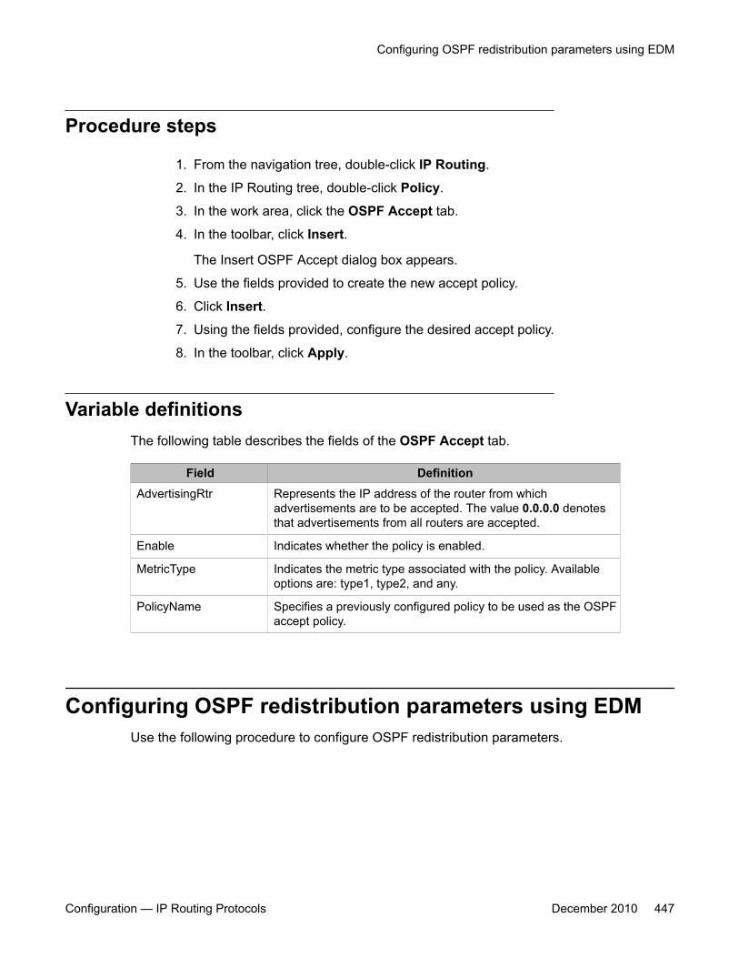
Procedure steps
1. From the navigation tree, double-click IP Routing.
2. In the IP Routing tree, double-click Policy.
3. In the work area, click the OSPF Accept tab.
4. In the toolbar, click Insert.
The Insert OSPF Accept dialog box appears.
5. Use the fields provided to create the new accept policy.
6. Click Insert.
7. Using the fields provided, configure the desired accept policy.
8. In the toolbar, click Apply.
Variable definitionsThe following table describes the fields of the OSPF Accept tab.
Field DefinitionAdvertisingRtr Represents the IP address of the router from which
advertisements are to be accepted. The value 0.0.0.0 denotesthat advertisements from all routers are accepted.
Enable Indicates whether the policy is enabled.
MetricType Indicates the metric type associated with the policy. Availableoptions are: type1, type2, and any.
PolicyName Specifies a previously configured policy to be used as the OSPFaccept policy.
Configuring OSPF redistribution parameters using EDMUse the following procedure to configure OSPF redistribution parameters.
Configuring OSPF redistribution parameters using EDM
Configuration — IP Routing Protocols December 2010 447
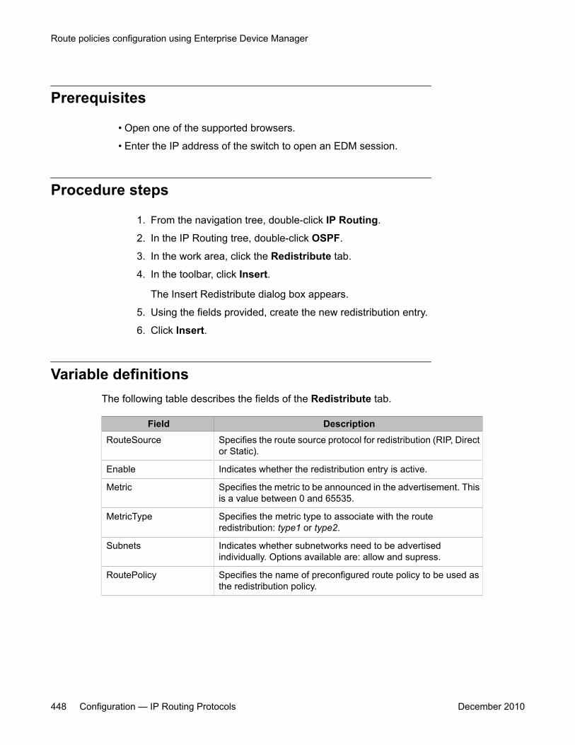
Prerequisites
• Open one of the supported browsers.
• Enter the IP address of the switch to open an EDM session.
Procedure steps
1. From the navigation tree, double-click IP Routing.
2. In the IP Routing tree, double-click OSPF.
3. In the work area, click the Redistribute tab.
4. In the toolbar, click Insert.
The Insert Redistribute dialog box appears.
5. Using the fields provided, create the new redistribution entry.
6. Click Insert.
Variable definitionsThe following table describes the fields of the Redistribute tab.
Field DescriptionRouteSource Specifies the route source protocol for redistribution (RIP, Direct
or Static).
Enable Indicates whether the redistribution entry is active.
Metric Specifies the metric to be announced in the advertisement. Thisis a value between 0 and 65535.
MetricType Specifies the metric type to associate with the routeredistribution: type1 or type2.
Subnets Indicates whether subnetworks need to be advertisedindividually. Options available are: allow and supress.
RoutePolicy Specifies the name of preconfigured route policy to be used asthe redistribution policy.
Route policies configuration using Enterprise Device Manager
448 Configuration — IP Routing Protocols December 2010
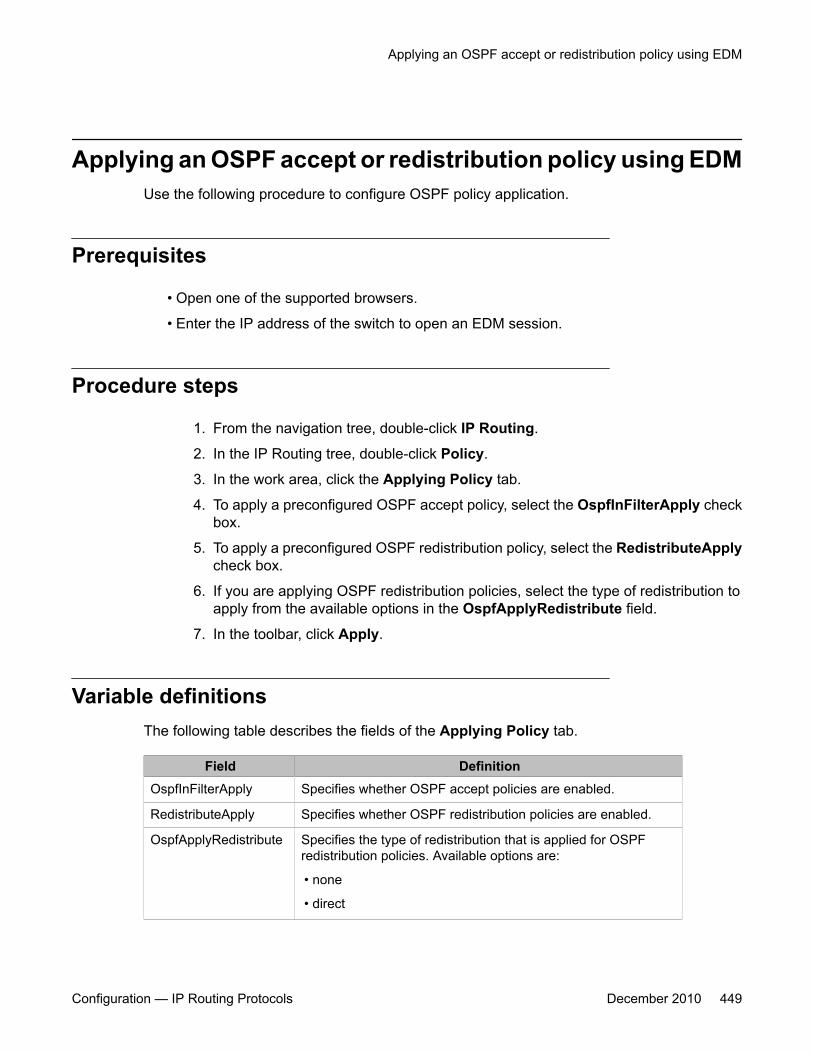
Applying an OSPF accept or redistribution policy using EDMUse the following procedure to configure OSPF policy application.
Prerequisites
• Open one of the supported browsers.
• Enter the IP address of the switch to open an EDM session.
Procedure steps
1. From the navigation tree, double-click IP Routing.
2. In the IP Routing tree, double-click Policy.
3. In the work area, click the Applying Policy tab.
4. To apply a preconfigured OSPF accept policy, select the OspfInFilterApply checkbox.
5. To apply a preconfigured OSPF redistribution policy, select the RedistributeApplycheck box.
6. If you are applying OSPF redistribution policies, select the type of redistribution toapply from the available options in the OspfApplyRedistribute field.
7. In the toolbar, click Apply.
Variable definitionsThe following table describes the fields of the Applying Policy tab.
Field DefinitionOspfInFilterApply Specifies whether OSPF accept policies are enabled.
RedistributeApply Specifies whether OSPF redistribution policies are enabled.
OspfApplyRedistribute Specifies the type of redistribution that is applied for OSPFredistribution policies. Available options are:
• none
• direct
Applying an OSPF accept or redistribution policy using EDM
Configuration — IP Routing Protocols December 2010 449

Field Definition
• static
• ip
Configuring the global IP forwarding next-hop statusUse this procedure to globally enable IP forwarding next-hop on the switch.
Procedure steps
1. From the navigation tree, double-click IP Routing.
2. In the IP Routing tree, double-click IP.
3. In the Globals tab, select the ForwardingNextHopAdminEnabled box.
4. Click Apply.
Configuring an IP forwarding next-hop policyUse this procedure to configure a policy for IP forwarding next-hop.
Procedure steps
1. From the navigation tree, double-click IP Routing.
2. In the IP Routing tree, double-click Forwarding-nh Policy.
3. Click Insert.
4. Complete the fields as required.
5. Click Insert.
6. Click Apply.
Variable definitionsThe following table describes the fields of the Applying Policy tab.
Route policies configuration using Enterprise Device Manager
450 Configuration — IP Routing Protocols December 2010
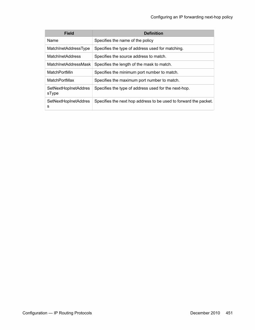
Field DefinitionName Specifies the name of the policy
MatchInetAddressType Specifies the type of address used for matching.
MatchInetAddress Specifies the source address to match.
MatchInetAddressMask Specifies the length of the mask to match.
MatchPortMin Specifies the minimum port number to match.
MatchPortMax Specifies the maximum port number to match.
SetNextHopInetAddressType
Specifies the type of address used for the next-hop.
SetNextHopInetAddress
Specifies the next hop address to be used to forward the packet.
Configuring an IP forwarding next-hop policy
Configuration — IP Routing Protocols December 2010 451

Route policies configuration using Enterprise Device Manager
452 Configuration — IP Routing Protocols December 2010
Chapter 35: DHCP relay configuration usingEnterprise Device Manager
The following chapter describe the procedures you can use to configure DHCP relay using EnterpriseDevice Manager (EDM).
Prerequisites• Enable IP routing globally.
• Enable IP routing and configure an IP address on the VLAN to be set as the DHCP relayagent.
• Ensure that a route to the destination DHCP server is available on the switch.
Configuring DHCP relay using EDMUse the following procedure to configure DHCP relay using EDM.
1. Enable DHCP relay globally.
2. Configure the DHCP relay forwarding path by specifying the VLAN IP as the DHCPrelay agent and the remote DHCP server as the destination.
3. Enable DHCP relay on the VLAN.
Navigation
• Configuring global DHCP Relay status and parameters on page 454
• Configuring a DHCP Relay forwarding path using EDM on page 454
• Configuring DHCP parameters on a VLAN using EDM on page 456
• Configuring DHCP Relay option 82 on a VLAN on page 457
• Configuring DHCP Relay option 82 on a port on page 457
Configuration — IP Routing Protocols December 2010 453
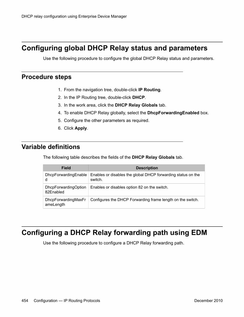
Configuring global DHCP Relay status and parametersUse the following procedure to configure the global DHCP Relay status and parameters.
Procedure steps
1. From the navigation tree, double-click IP Routing.
2. In the IP Routing tree, double-click DHCP.
3. In the work area, click the DHCP Relay Globals tab.
4. To enable DHCP Relay globally, select the DhcpForwardingEnabled box.
5. Configure the other parameters as required.
6. Click Apply.
Variable definitionsThe following table describes the fields of the DHCP Relay Globals tab.
Field DescriptionDhcpForwardingEnabled
Enables or disables the global DHCP forwarding status on theswitch.
DhcpForwardingOption82Enabled
Enables or disables option 82 on the switch.
DhcpForwardingMaxFrameLength
Configures the DHCP Forwarding frame length on the switch.
Configuring a DHCP Relay forwarding path using EDMUse the following procedure to configure a DHCP Relay forwarding path.
DHCP relay configuration using Enterprise Device Manager
454 Configuration — IP Routing Protocols December 2010
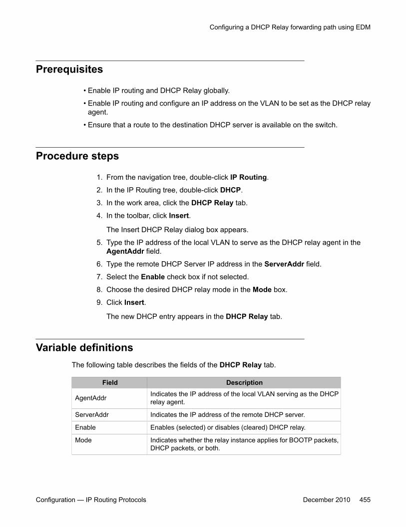
Prerequisites
• Enable IP routing and DHCP Relay globally.
• Enable IP routing and configure an IP address on the VLAN to be set as the DHCP relayagent.
• Ensure that a route to the destination DHCP server is available on the switch.
Procedure steps
1. From the navigation tree, double-click IP Routing.
2. In the IP Routing tree, double-click DHCP.
3. In the work area, click the DHCP Relay tab.
4. In the toolbar, click Insert.
The Insert DHCP Relay dialog box appears.
5. Type the IP address of the local VLAN to serve as the DHCP relay agent in theAgentAddr field.
6. Type the remote DHCP Server IP address in the ServerAddr field.
7. Select the Enable check box if not selected.
8. Choose the desired DHCP relay mode in the Mode box.
9. Click Insert.
The new DHCP entry appears in the DHCP Relay tab.
Variable definitionsThe following table describes the fields of the DHCP Relay tab.
Field Description
AgentAddr Indicates the IP address of the local VLAN serving as the DHCPrelay agent.
ServerAddr Indicates the IP address of the remote DHCP server.
Enable Enables (selected) or disables (cleared) DHCP relay.
Mode Indicates whether the relay instance applies for BOOTP packets,DHCP packets, or both.
Configuring a DHCP Relay forwarding path using EDM
Configuration — IP Routing Protocols December 2010 455
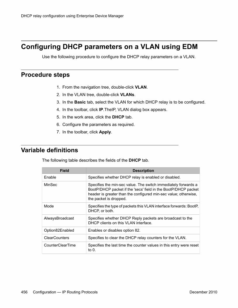
Configuring DHCP parameters on a VLAN using EDMUse the following procedure to configure the DHCP relay parameters on a VLAN.
Procedure steps
1. From the navigation tree, double-click VLAN.
2. In the VLAN tree, double-click VLANs.
3. In the Basic tab, select the VLAN for which DHCP relay is to be configured.
4. In the toolbar, click IP.TheIP, VLAN dialog box appears.
5. In the work area, click the DHCP tab.
6. Configure the parameters as required.
7. In the toolbar, click Apply.
Variable definitionsThe following table describes the fields of the DHCP tab.
Field DescriptionEnable Specifies whether DHCP relay is enabled or disabled.
MinSec Specifies the min-sec value. The switch immediately forwards aBootP/DHCP packet if the 'secs' field in the BootP/DHCP packetheader is greater than the configured min-sec value; otherwise,the packet is dropped.
Mode Specifies the type of packets this VLAN interface forwards: BootP,DHCP, or both.
AlwaysBroadcast Specifies whether DHCP Reply packets are broadcast to theDHCP clients on this VLAN interface.
Option82Enabled Enables or disables option 82.
ClearCounters Specifies to clear the DHCP relay counters for the VLAN.
CounterClearTime Specifies the last time the counter values in this entry were resetto 0.
DHCP relay configuration using Enterprise Device Manager
456 Configuration — IP Routing Protocols December 2010
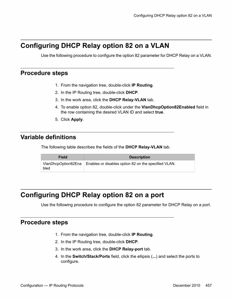
Configuring DHCP Relay option 82 on a VLANUse the following procedure to configure the option 82 parameter for DHCP Relay on a VLAN.
Procedure steps
1. From the navigation tree, double-click IP Routing.
2. In the IP Routing tree, double-click DHCP.
3. In the work area, click the DHCP Relay-VLAN tab.
4. To enable option 82, double-click under the VlanDhcpOption82Enabled field inthe row containing the desired VLAN ID and select true.
5. Click Apply.
Variable definitionsThe following table describes the fields of the DHCP Relay-VLAN tab.
Field DescriptionVlanDhcpOption82Enabled
Enables or disables option 82 on the specified VLAN.
Configuring DHCP Relay option 82 on a portUse the following procedure to configure the option 82 parameter for DHCP Relay on a port.
Procedure steps
1. From the navigation tree, double-click IP Routing.
2. In the IP Routing tree, double-click DHCP.
3. In the work area, click the DHCP Relay-port tab.
4. In the Switch/Stack/Ports field, click the ellipsis (...) and select the ports toconfigure.
Configuring DHCP Relay option 82 on a VLAN
Configuration — IP Routing Protocols December 2010 457

5. Under the PortDhcpOption82SubscriberId field, enter a subscriber ID.
6. Click Apply Selection.
Variable definitionsThe following table describes the fields of the DHCP Relay-port tab.
Field DescriptionPortDhcpOption82SubscriberId
Specifies a subscriber ID for option 82 on the specified port.
DHCP relay configuration using Enterprise Device Manager
458 Configuration — IP Routing Protocols December 2010
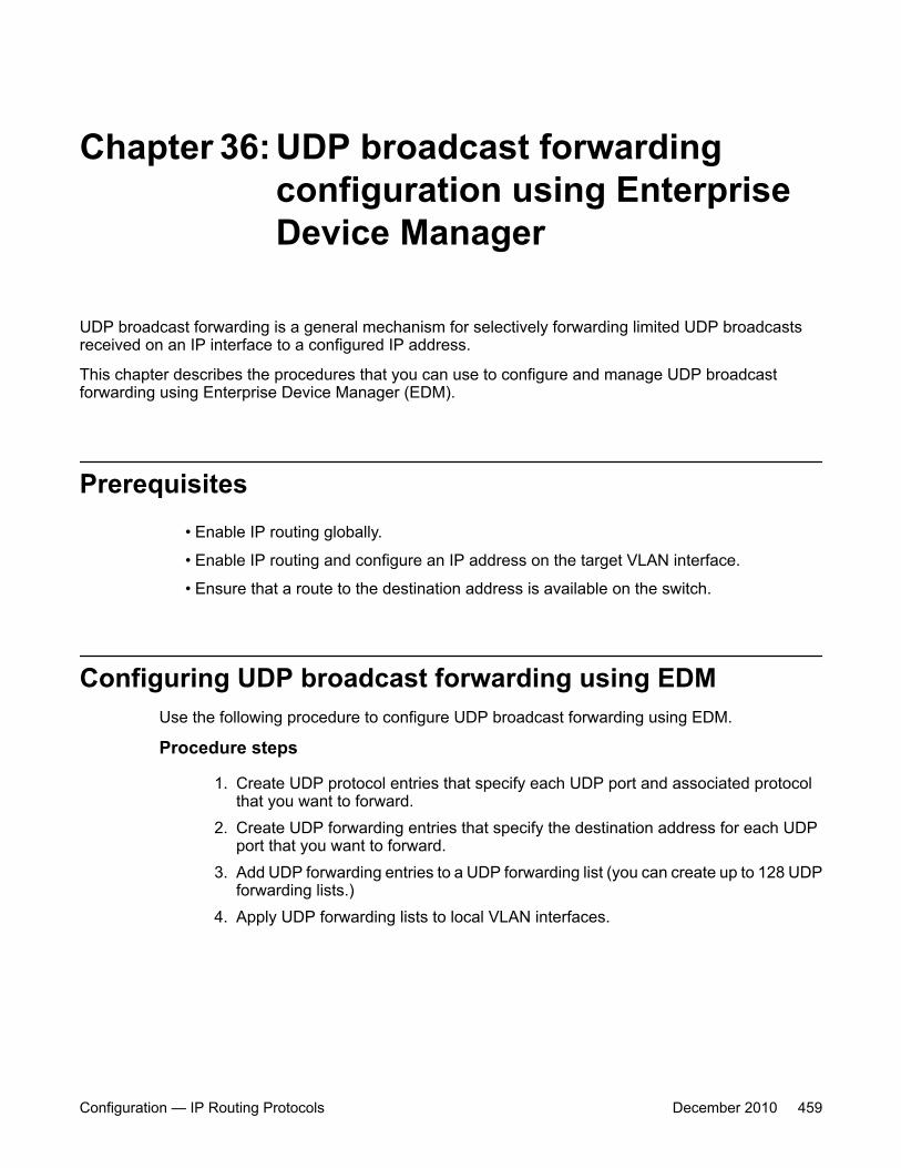
Chapter 36: UDP broadcast forwardingconfiguration using EnterpriseDevice Manager
UDP broadcast forwarding is a general mechanism for selectively forwarding limited UDP broadcastsreceived on an IP interface to a configured IP address.
This chapter describes the procedures that you can use to configure and manage UDP broadcastforwarding using Enterprise Device Manager (EDM).
Prerequisites• Enable IP routing globally.
• Enable IP routing and configure an IP address on the target VLAN interface.
• Ensure that a route to the destination address is available on the switch.
Configuring UDP broadcast forwarding using EDMUse the following procedure to configure UDP broadcast forwarding using EDM.
Procedure steps
1. Create UDP protocol entries that specify each UDP port and associated protocolthat you want to forward.
2. Create UDP forwarding entries that specify the destination address for each UDPport that you want to forward.
3. Add UDP forwarding entries to a UDP forwarding list (you can create up to 128 UDPforwarding lists.)
4. Apply UDP forwarding lists to local VLAN interfaces.
Configuration — IP Routing Protocols December 2010 459
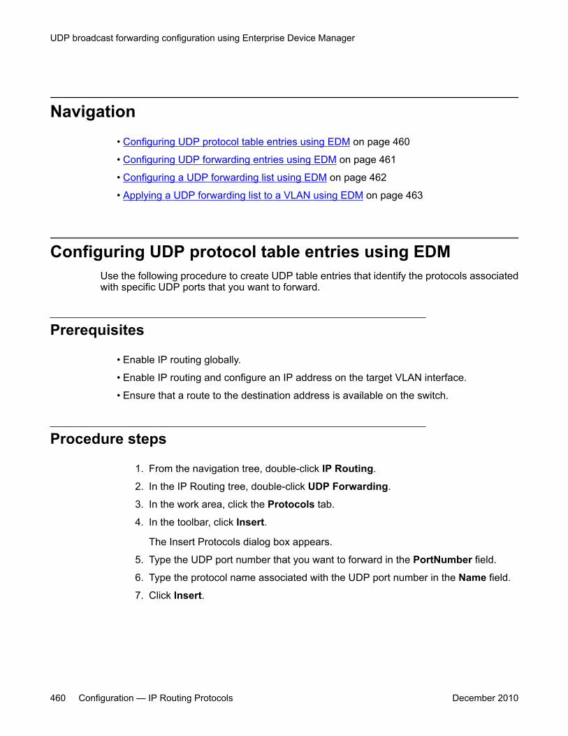
Navigation• Configuring UDP protocol table entries using EDM on page 460
• Configuring UDP forwarding entries using EDM on page 461
• Configuring a UDP forwarding list using EDM on page 462
• Applying a UDP forwarding list to a VLAN using EDM on page 463
Configuring UDP protocol table entries using EDMUse the following procedure to create UDP table entries that identify the protocols associatedwith specific UDP ports that you want to forward.
Prerequisites
• Enable IP routing globally.
• Enable IP routing and configure an IP address on the target VLAN interface.
• Ensure that a route to the destination address is available on the switch.
Procedure steps
1. From the navigation tree, double-click IP Routing.
2. In the IP Routing tree, double-click UDP Forwarding.
3. In the work area, click the Protocols tab.
4. In the toolbar, click Insert.
The Insert Protocols dialog box appears.
5. Type the UDP port number that you want to forward in the PortNumber field.
6. Type the protocol name associated with the UDP port number in the Name field.
7. Click Insert.
UDP broadcast forwarding configuration using Enterprise Device Manager
460 Configuration — IP Routing Protocols December 2010

Variable definitionsThe following table describes the fields of the Protocols tab.
Field DescriptionPortNumber Specifies the UDP port number.
Name Specifies the protocol name associated with the UDP port.
Configuring UDP forwarding entries using EDMUse the following procedure to configure individual UDP forwarding list entries, which associateUDP forwarding ports with destination IP addresses.
Prerequisites
• Enable IP routing globally.
• Enable IP routing and configure an IP address on the target VLAN interface.
• Ensure that a route to the destination address is available on the switch.
Procedure steps
1. From the navigation tree, double-click IP Routing.
2. In the IP Routing tree, double-click UDP Forwarding.
3. In the work area, click the Forwarding tab.
4. In the toolbar, click Insert.
The Insert Forwardings dialog box appears.
5. Using the provided fields, specify a destination address for a selected port.
6. Click Insert.
Variable definitionsThe following table describes the fields of the Forwardings tab.
Configuring UDP forwarding entries using EDM
Configuration — IP Routing Protocols December 2010 461

Field DescriptionDestPort Specifies the port on which the UDP forwarding originates
(configured using the Protocols tab).
DestAddr Specifies the destination IP address.
Id Specifies an ID for the entry.
FwdListIdList Indicates the UDP forward list with which this entry is associated(using the Forwarding Lists tab).
Configuring a UDP forwarding list using EDMUse the following procedure to add the UDP port/destination forwarding list entries (configuredin the Forwardings tab) to UDP forwarding lists. Each UDP forwarding list can contain multipleport/destination entries.
Prerequisites
• Enable IP routing globally.
• Enable IP routing and configure an IP address on the target VLAN interface.
• Ensure that a route to the destination address is available on the switch.
Procedure steps
1. From the navigation tree, double-click IP Routing.
2. In the IP Routing tree, double-click UDP Forwarding.
3. In the work area, click the Forwarding Lists tab.
4. In the toolbar, click Insert.
The Insert Forwarding Lists dialog box appears.
5. Assign a unique ID to the UDP forwarding list in the Id field.
6. Type a unique name for the UDP forwarding list in the Name field.
7. Click the FwdIdList (...) to select the desired port/destination pairs from the list.
8. Click Insert.
UDP broadcast forwarding configuration using Enterprise Device Manager
462 Configuration — IP Routing Protocols December 2010
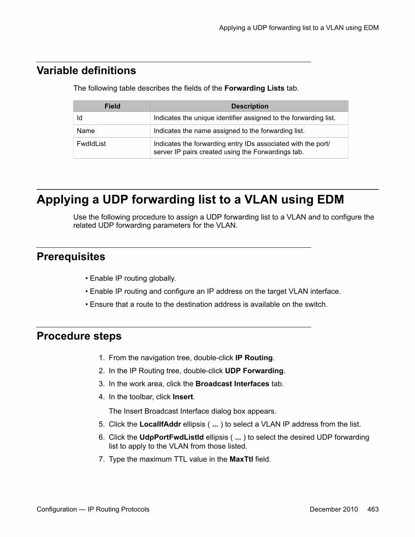
Variable definitionsThe following table describes the fields of the Forwarding Lists tab.
Field DescriptionId Indicates the unique identifier assigned to the forwarding list.
Name Indicates the name assigned to the forwarding list.
FwdIdList Indicates the forwarding entry IDs associated with the port/server IP pairs created using the Forwardings tab.
Applying a UDP forwarding list to a VLAN using EDMUse the following procedure to assign a UDP forwarding list to a VLAN and to configure therelated UDP forwarding parameters for the VLAN.
Prerequisites
• Enable IP routing globally.
• Enable IP routing and configure an IP address on the target VLAN interface.
• Ensure that a route to the destination address is available on the switch.
Procedure steps
1. From the navigation tree, double-click IP Routing.
2. In the IP Routing tree, double-click UDP Forwarding.
3. In the work area, click the Broadcast Interfaces tab.
4. In the toolbar, click Insert.
The Insert Broadcast Interface dialog box appears.
5. Click the LocalIfAddr ellipsis ( ... ) to select a VLAN IP address from the list.
6. Click the UdpPortFwdListId ellipsis ( ... ) to select the desired UDP forwardinglist to apply to the VLAN from those listed.
7. Type the maximum TTL value in the MaxTtl field.
Applying a UDP forwarding list to a VLAN using EDM
Configuration — IP Routing Protocols December 2010 463
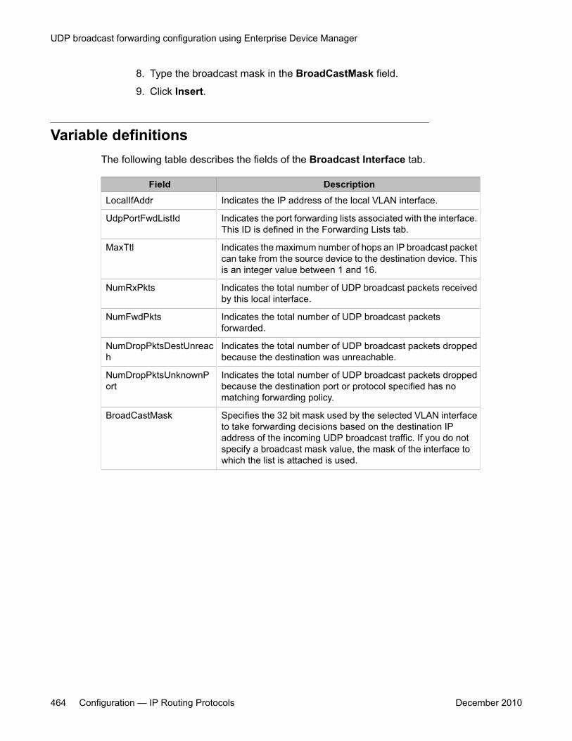
8. Type the broadcast mask in the BroadCastMask field.
9. Click Insert.
Variable definitionsThe following table describes the fields of the Broadcast Interface tab.
Field DescriptionLocalIfAddr Indicates the IP address of the local VLAN interface.
UdpPortFwdListId Indicates the port forwarding lists associated with the interface.This ID is defined in the Forwarding Lists tab.
MaxTtl Indicates the maximum number of hops an IP broadcast packetcan take from the source device to the destination device. Thisis an integer value between 1 and 16.
NumRxPkts Indicates the total number of UDP broadcast packets receivedby this local interface.
NumFwdPkts Indicates the total number of UDP broadcast packetsforwarded.
NumDropPktsDestUnreach
Indicates the total number of UDP broadcast packets droppedbecause the destination was unreachable.
NumDropPktsUnknownPort
Indicates the total number of UDP broadcast packets droppedbecause the destination port or protocol specified has nomatching forwarding policy.
BroadCastMask Specifies the 32 bit mask used by the selected VLAN interfaceto take forwarding decisions based on the destination IPaddress of the incoming UDP broadcast traffic. If you do notspecify a broadcast mask value, the mask of the interface towhich the list is attached is used.
UDP broadcast forwarding configuration using Enterprise Device Manager
464 Configuration — IP Routing Protocols December 2010
Chapter 37: Static ARP and Proxy ARPconfiguration using EnterpriseDevice Manager
This chapter describes the procedures you can use to configure static ARP and proxy ARP usingEnterprise Device Manager (EDM).
Prerequisites• Enable IP routing globally.
• Enable IP routing and configure an IP address on the VLAN to be configured as a ProxyARP interface.
Navigation• Configuring static ARP entries using EDM on page 465
• Configuring Proxy ARP using EDM on page 466
Configuring static ARP entries using EDMUse the following procedure to configure static ARP entries for the switch.
Prerequisites
• Enable IP routing globally.
• Enable IP routing and configure an IP address on the target VLAN interface.
Configuration — IP Routing Protocols December 2010 465
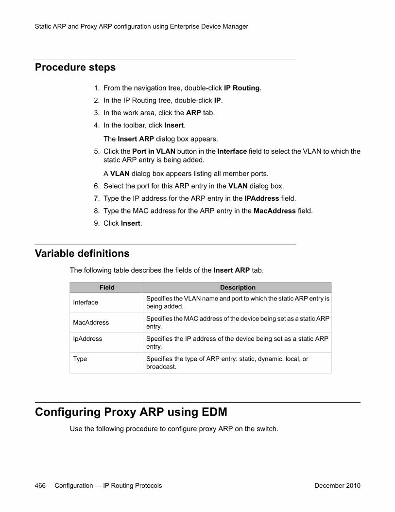
Procedure steps
1. From the navigation tree, double-click IP Routing.
2. In the IP Routing tree, double-click IP.
3. In the work area, click the ARP tab.
4. In the toolbar, click Insert.
The Insert ARP dialog box appears.
5. Click the Port in VLAN button in the Interface field to select the VLAN to which thestatic ARP entry is being added.
A VLAN dialog box appears listing all member ports.
6. Select the port for this ARP entry in the VLAN dialog box.
7. Type the IP address for the ARP entry in the IPAddress field.
8. Type the MAC address for the ARP entry in the MacAddress field.
9. Click Insert.
Variable definitionsThe following table describes the fields of the Insert ARP tab.
Field Description
Interface Specifies the VLAN name and port to which the static ARP entry isbeing added.
MacAddress Specifies the MAC address of the device being set as a static ARPentry.
IpAddress Specifies the IP address of the device being set as a static ARPentry.
Type Specifies the type of ARP entry: static, dynamic, local, orbroadcast.
Configuring Proxy ARP using EDMUse the following procedure to configure proxy ARP on the switch.
Static ARP and Proxy ARP configuration using Enterprise Device Manager
466 Configuration — IP Routing Protocols December 2010
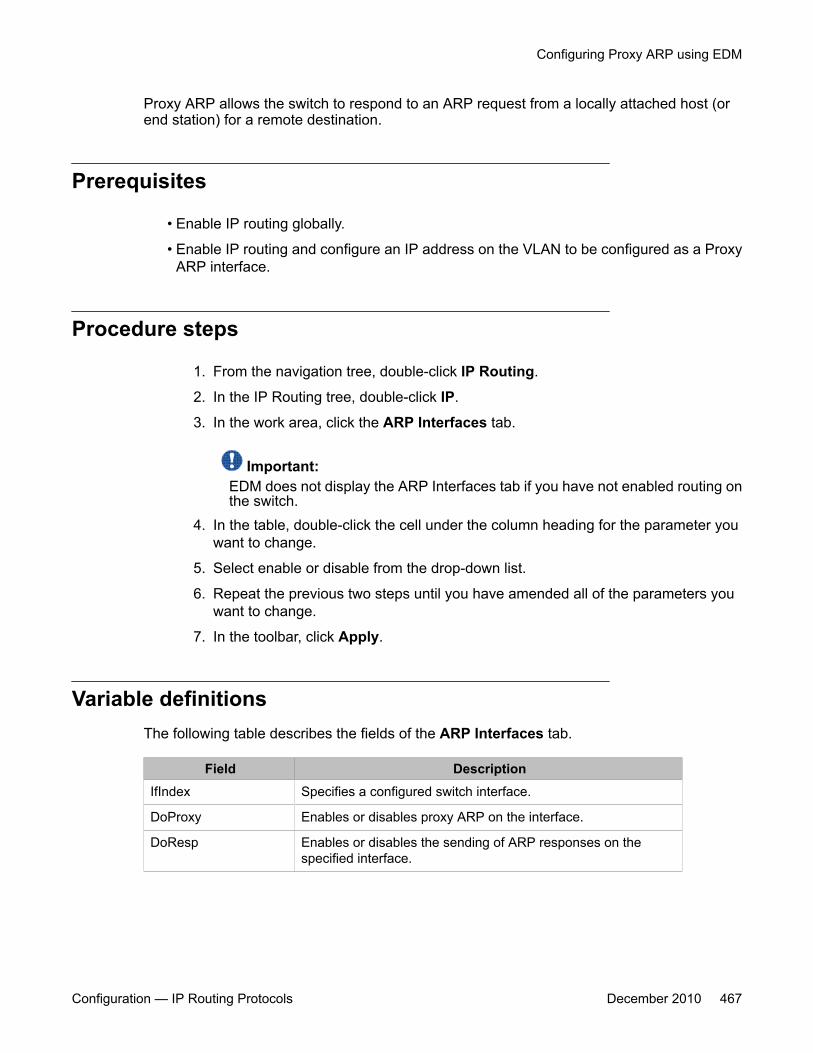
Proxy ARP allows the switch to respond to an ARP request from a locally attached host (orend station) for a remote destination.
Prerequisites
• Enable IP routing globally.
• Enable IP routing and configure an IP address on the VLAN to be configured as a ProxyARP interface.
Procedure steps
1. From the navigation tree, double-click IP Routing.
2. In the IP Routing tree, double-click IP.
3. In the work area, click the ARP Interfaces tab.
Important:EDM does not display the ARP Interfaces tab if you have not enabled routing onthe switch.
4. In the table, double-click the cell under the column heading for the parameter youwant to change.
5. Select enable or disable from the drop-down list.
6. Repeat the previous two steps until you have amended all of the parameters youwant to change.
7. In the toolbar, click Apply.
Variable definitionsThe following table describes the fields of the ARP Interfaces tab.
Field DescriptionIfIndex Specifies a configured switch interface.
DoProxy Enables or disables proxy ARP on the interface.
DoResp Enables or disables the sending of ARP responses on thespecified interface.
Configuring Proxy ARP using EDM
Configuration — IP Routing Protocols December 2010 467

Static ARP and Proxy ARP configuration using Enterprise Device Manager
468 Configuration — IP Routing Protocols December 2010

Chapter 38: VRRP configuration usingEnterprise Device Manager
This chapter describes the procedures you can use to configure VRRP using Enterprise Device Manager(EDM).
The Virtual Router Redundancy Protocol (VRRP) is designed to eliminate the single point of failure thatcan occur when the single static default gateway router for an end station is lost.
Prerequisites• Install the Advanced License.
• Enable IP routing globally on the switch.
• Assign an IP address to the VLAN that you want to enable with VRRP.
Routing is automatically enabled on the VLAN when you assign an IP address to it.
Configuring VRRP using EDMUse the following procedure to enable VRRP on a VLAN.
Procedure steps
1. Enable VRRP globally on the switch.2. Assign a virtual router IP address to a virtual router ID.3. Configure the priority for this router as required and enable the virtual router.
Navigation• Configuring global VRRP status and properties using EDM on page 470
• Assigning an IP address to a virtual router ID using EDM on page 471
Configuration — IP Routing Protocols December 2010 469

• Configuring VRRP interface properties using EDM on page 472
• Graphing VRRP interface information using EDM on page 474
• Viewing general VRRP statistics using EDM on page 476
Configuring global VRRP status and properties using EDMUse the following procedure to configure global VRRP settings.
Prerequisites
• Install the Advanced License.
• Enable IP routing globally on the switch.
• Assign an IP address to the VLAN that you want to enable with VRRP.
Routing is automatically enabled on the VLAN when you assign an IP address to it.
Procedure steps
1. From the navigation tree, double-click IP Routing.
2. In the IP Routing tree, double-click VRRP.
3. In the work area, click the Globals tab.
4. Configure the global VRRP parameters as required.
5. In the toolbar, click Apply.
Variable definitionsThe following table describes the fields of the VRRP—Globals tab.
Field DefinitionEnabled Indicates whether VRRP is globally enabled on the switch.
Version Indicates the version of VRRP supported on this switch.
NotificationCntl Indicates whether the VRRP-enabled router generates SimpleNetwork Management Protocol (SNMP) traps based on VRRPevents:
VRRP configuration using Enterprise Device Manager
470 Configuration — IP Routing Protocols December 2010
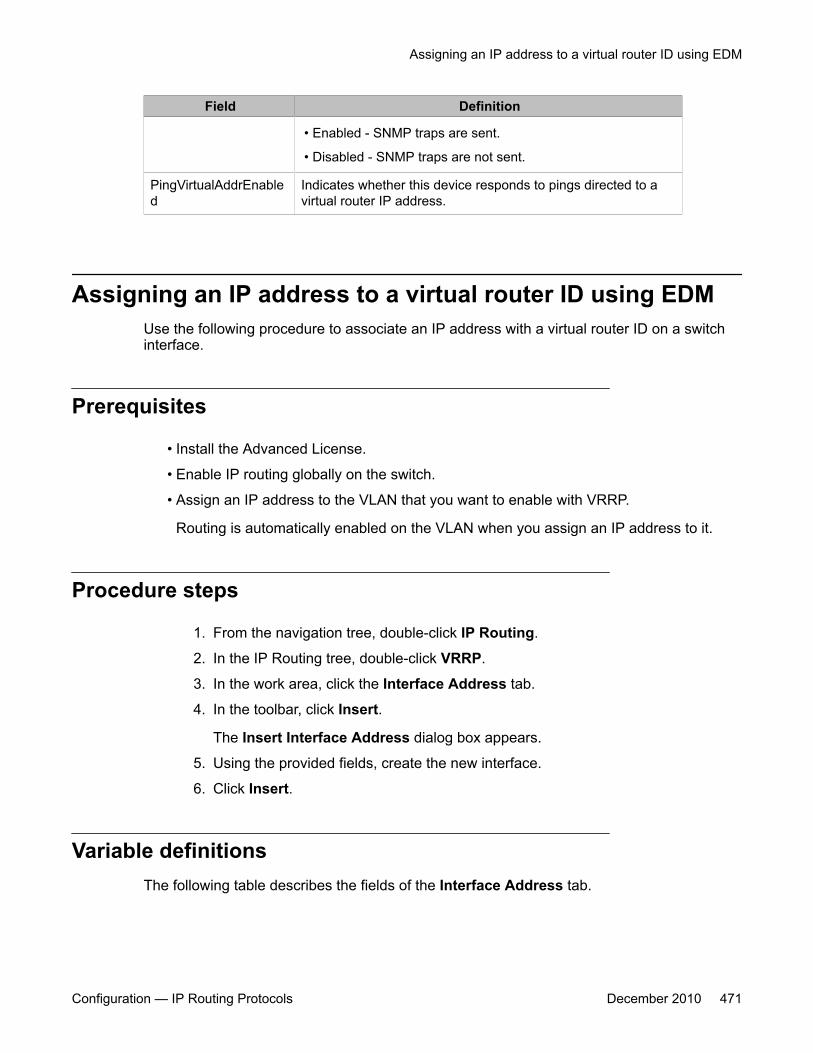
Field Definition
• Enabled - SNMP traps are sent.
• Disabled - SNMP traps are not sent.
PingVirtualAddrEnabled
Indicates whether this device responds to pings directed to avirtual router IP address.
Assigning an IP address to a virtual router ID using EDMUse the following procedure to associate an IP address with a virtual router ID on a switchinterface.
Prerequisites
• Install the Advanced License.
• Enable IP routing globally on the switch.
• Assign an IP address to the VLAN that you want to enable with VRRP.
Routing is automatically enabled on the VLAN when you assign an IP address to it.
Procedure steps
1. From the navigation tree, double-click IP Routing.
2. In the IP Routing tree, double-click VRRP.
3. In the work area, click the Interface Address tab.
4. In the toolbar, click Insert.
The Insert Interface Address dialog box appears.
5. Using the provided fields, create the new interface.
6. Click Insert.
Variable definitionsThe following table describes the fields of the Interface Address tab.
Assigning an IP address to a virtual router ID using EDM
Configuration — IP Routing Protocols December 2010 471
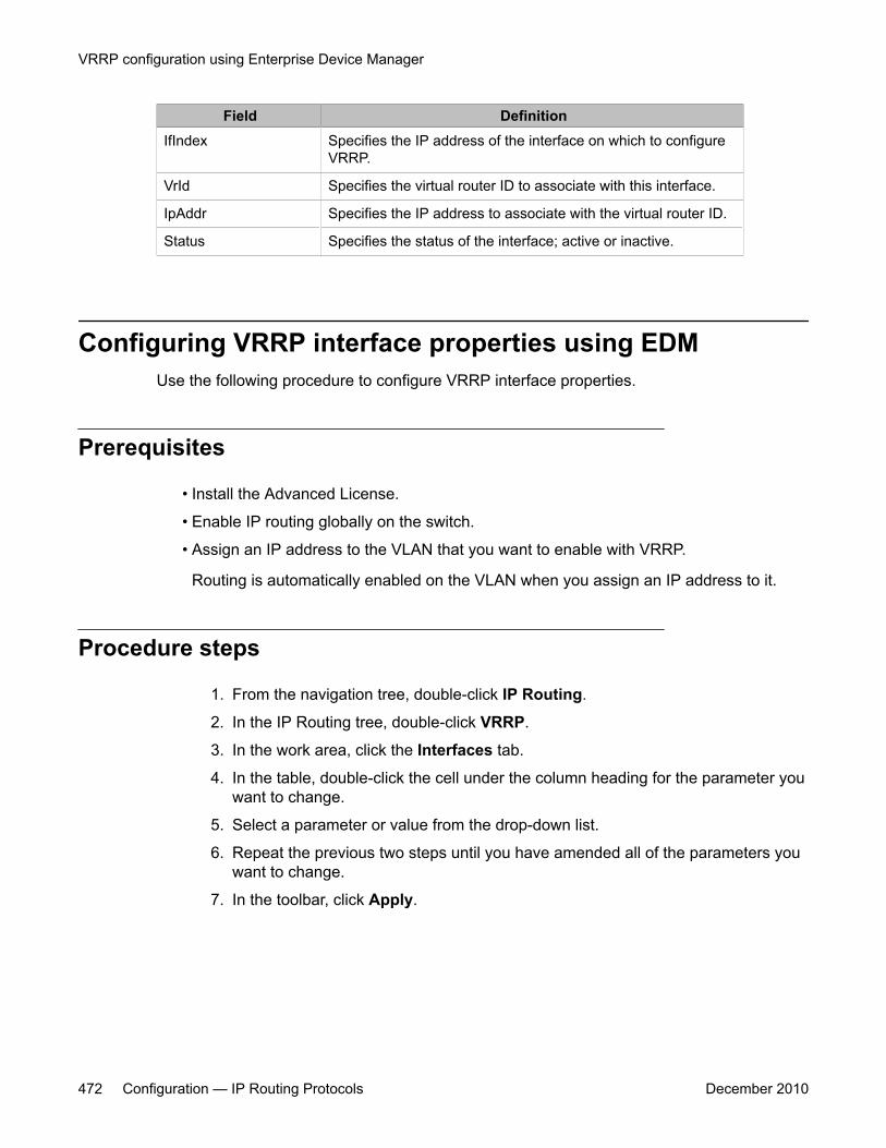
Field DefinitionIfIndex Specifies the IP address of the interface on which to configure
VRRP.
VrId Specifies the virtual router ID to associate with this interface.
IpAddr Specifies the IP address to associate with the virtual router ID.
Status Specifies the status of the interface; active or inactive.
Configuring VRRP interface properties using EDMUse the following procedure to configure VRRP interface properties.
Prerequisites
• Install the Advanced License.
• Enable IP routing globally on the switch.
• Assign an IP address to the VLAN that you want to enable with VRRP.
Routing is automatically enabled on the VLAN when you assign an IP address to it.
Procedure steps
1. From the navigation tree, double-click IP Routing.
2. In the IP Routing tree, double-click VRRP.
3. In the work area, click the Interfaces tab.
4. In the table, double-click the cell under the column heading for the parameter youwant to change.
5. Select a parameter or value from the drop-down list.
6. Repeat the previous two steps until you have amended all of the parameters youwant to change.
7. In the toolbar, click Apply.
VRRP configuration using Enterprise Device Manager
472 Configuration — IP Routing Protocols December 2010
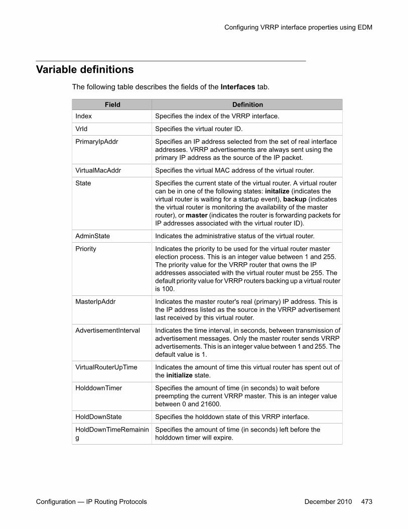
Variable definitionsThe following table describes the fields of the Interfaces tab.
Field DefinitionIndex Specifies the index of the VRRP interface.
VrId Specifies the virtual router ID.
PrimaryIpAddr Specifies an IP address selected from the set of real interfaceaddresses. VRRP advertisements are always sent using theprimary IP address as the source of the IP packet.
VirtualMacAddr Specifies the virtual MAC address of the virtual router.
State Specifies the current state of the virtual router. A virtual routercan be in one of the following states: initalize (indicates thevirtual router is waiting for a startup event), backup (indicatesthe virtual router is monitoring the availability of the masterrouter), or master (indicates the router is forwarding packets forIP addresses associated with the virtual router ID).
AdminState Indicates the administrative status of the virtual router.
Priority Indicates the priority to be used for the virtual router masterelection process. This is an integer value between 1 and 255.The priority value for the VRRP router that owns the IPaddresses associated with the virtual router must be 255. Thedefault priority value for VRRP routers backing up a virtual routeris 100.
MasterIpAddr Indicates the master router's real (primary) IP address. This isthe IP address listed as the source in the VRRP advertisementlast received by this virtual router.
AdvertisementInterval Indicates the time interval, in seconds, between transmission ofadvertisement messages. Only the master router sends VRRPadvertisements. This is an integer value between 1 and 255. Thedefault value is 1.
VirtualRouterUpTime Indicates the amount of time this virtual router has spent out ofthe initialize state.
HolddownTimer Specifies the amount of time (in seconds) to wait beforepreempting the current VRRP master. This is an integer valuebetween 0 and 21600.
HoldDownState Specifies the holddown state of this VRRP interface.
HoldDownTimeRemaining
Specifies the amount of time (in seconds) left before theholddown timer will expire.
Configuring VRRP interface properties using EDM
Configuration — IP Routing Protocols December 2010 473
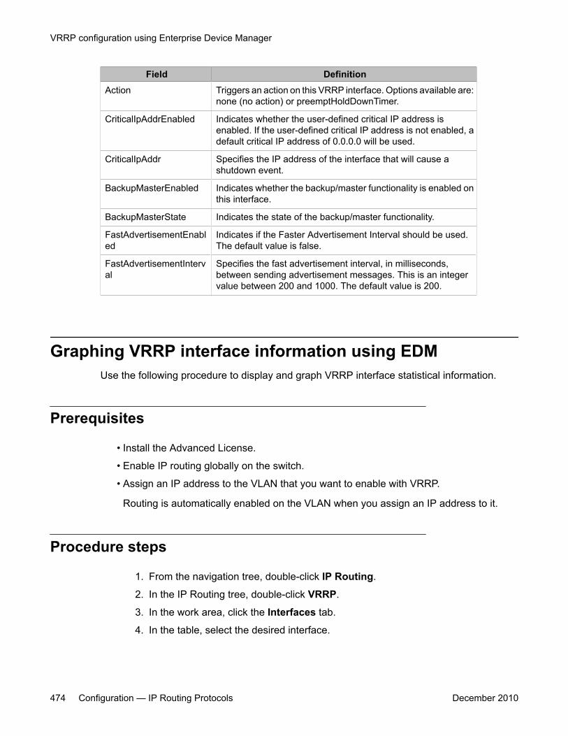
Field DefinitionAction Triggers an action on this VRRP interface. Options available are:
none (no action) or preemptHoldDownTimer.
CriticalIpAddrEnabled Indicates whether the user-defined critical IP address isenabled. If the user-defined critical IP address is not enabled, adefault critical IP address of 0.0.0.0 will be used.
CriticalIpAddr Specifies the IP address of the interface that will cause ashutdown event.
BackupMasterEnabled Indicates whether the backup/master functionality is enabled onthis interface.
BackupMasterState Indicates the state of the backup/master functionality.
FastAdvertisementEnabled
Indicates if the Faster Advertisement Interval should be used.The default value is false.
FastAdvertisementInterval
Specifies the fast advertisement interval, in milliseconds,between sending advertisement messages. This is an integervalue between 200 and 1000. The default value is 200.
Graphing VRRP interface information using EDMUse the following procedure to display and graph VRRP interface statistical information.
Prerequisites
• Install the Advanced License.
• Enable IP routing globally on the switch.
• Assign an IP address to the VLAN that you want to enable with VRRP.
Routing is automatically enabled on the VLAN when you assign an IP address to it.
Procedure steps
1. From the navigation tree, double-click IP Routing.
2. In the IP Routing tree, double-click VRRP.
3. In the work area, click the Interfaces tab.
4. In the table, select the desired interface.
VRRP configuration using Enterprise Device Manager
474 Configuration — IP Routing Protocols December 2010
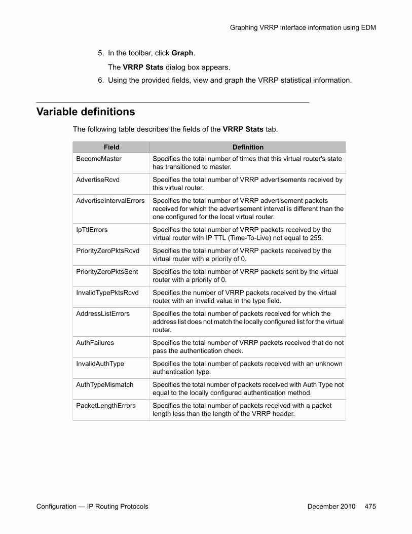
5. In the toolbar, click Graph.
The VRRP Stats dialog box appears.
6. Using the provided fields, view and graph the VRRP statistical information.
Variable definitionsThe following table describes the fields of the VRRP Stats tab.
Field DefinitionBecomeMaster Specifies the total number of times that this virtual router's state
has transitioned to master.
AdvertiseRcvd Specifies the total number of VRRP advertisements received bythis virtual router.
AdvertiseIntervalErrors Specifies the total number of VRRP advertisement packetsreceived for which the advertisement interval is different than theone configured for the local virtual router.
IpTtlErrors Specifies the total number of VRRP packets received by thevirtual router with IP TTL (Time-To-Live) not equal to 255.
PriorityZeroPktsRcvd Specifies the total number of VRRP packets received by thevirtual router with a priority of 0.
PriorityZeroPktsSent Specifies the total number of VRRP packets sent by the virtualrouter with a priority of 0.
InvalidTypePktsRcvd Specifies the number of VRRP packets received by the virtualrouter with an invalid value in the type field.
AddressListErrors Specifies the total number of packets received for which theaddress list does not match the locally configured list for the virtualrouter.
AuthFailures Specifies the total number of VRRP packets received that do notpass the authentication check.
InvalidAuthType Specifies the total number of packets received with an unknownauthentication type.
AuthTypeMismatch Specifies the total number of packets received with Auth Type notequal to the locally configured authentication method.
PacketLengthErrors Specifies the total number of packets received with a packetlength less than the length of the VRRP header.
Graphing VRRP interface information using EDM
Configuration — IP Routing Protocols December 2010 475
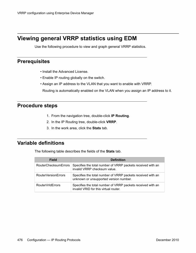
Viewing general VRRP statistics using EDMUse the following procedure to view and graph general VRRP statistics.
Prerequisites
• Install the Advanced License.
• Enable IP routing globally on the switch.
• Assign an IP address to the VLAN that you want to enable with VRRP.
Routing is automatically enabled on the VLAN when you assign an IP address to it.
Procedure steps
1. From the navigation tree, double-click IP Routing.
2. In the IP Routing tree, double-click VRRP.
3. In the work area, click the Stats tab.
Variable definitionsThe following table describes the fields of the Stats tab.
Field DefinitionRouterChecksumErrors Specifies the total number of VRRP packets received with an
invalid VRRP checksum value.
RouterVersionErrors Specifies the total number of VRRP packets received with anunknown or unsupported version number.
RouterVrIdErrors Specifies the total number of VRRP packets received with aninvalid VRID for this virtual router.
VRRP configuration using Enterprise Device Manager
476 Configuration — IP Routing Protocols December 2010
Chapter 39: IGMP snooping configurationusing Enterprise DeviceManager
This chapter describes the procedures you can use to configure IGMP snooping on a VLAN usingEnterprise Device Manager (EDM).
Prerequisites• Open one of the supported browsers.
• Enter the IP address of the switch to open an EDM session.
Configuring IGMP snooping using EDMEnable snoop on the VLAN.
All related configurations, listed below, are optional and can be configured to suit therequirements of your network.
Navigation• Configuring IGMP snoop, proxy, and IGMP parameters on a VLAN using EDM on
page 478
• Configuring IGMP snoop, proxy, and static mrouter ports on a VLAN using EDM onpage 480
• Flushing the IGMP router tables and configuring IGMP router alert using EDM onpage 481
• Configuring unknown multicast filtering using EDM on page 484
Configuration — IP Routing Protocols December 2010 477

• Specifying a multicast MAC address to be allowed to flood all VLANs using EDM onpage 485
• Specifying an IP address to be allowed to flood a VLAN using EDM on page 486
• Displaying IGMP cache information using EDM on page 487
• Displaying IGMP group information using EDM on page 488
• Displaying multicast route information using EDM on page 489
• Displaying multicast next hop information using EDM on page 490
• Displaying multicast interface information using EDM on page 491
• Creating an IGMP profile on page 327
• Configuring the IGMP Profile Range on page 493
Configuring IGMP snoop, proxy, and IGMP parameters on aVLAN using EDM
Use the following procedure to configure IGMP snoop, proxy, and IGMP parameters on aVLAN.
IGMP snoop and proxy are disabled by default.
Important:With IGMP snoop, the QueryInterval, Robustness, and Version values must be the same asthose configured on the interface (VLAN) of the multicast router (IGMP querier).
Prerequisites
• Open one of the supported browsers.
• Enter the IP address of the switch to open an EDM session.
Procedure steps
1. From the navigation tree, double-click VLAN.
2. In the VLAN tree, double-click VLANs.
3. In the work area, click the Snoop tab.
4. In the table, double-click the cell under the Enable column heading.
IGMP snooping configuration using Enterprise Device Manager
478 Configuration — IP Routing Protocols December 2010
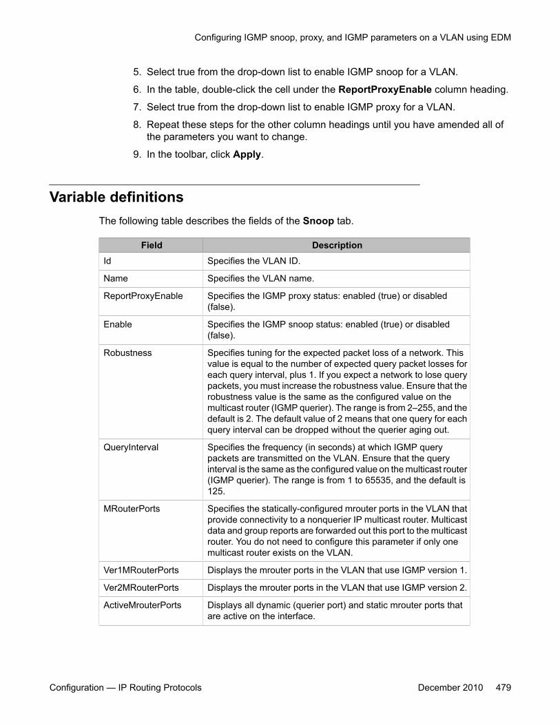
5. Select true from the drop-down list to enable IGMP snoop for a VLAN.
6. In the table, double-click the cell under the ReportProxyEnable column heading.
7. Select true from the drop-down list to enable IGMP proxy for a VLAN.
8. Repeat these steps for the other column headings until you have amended all ofthe parameters you want to change.
9. In the toolbar, click Apply.
Variable definitionsThe following table describes the fields of the Snoop tab.
Field DescriptionId Specifies the VLAN ID.
Name Specifies the VLAN name.
ReportProxyEnable Specifies the IGMP proxy status: enabled (true) or disabled(false).
Enable Specifies the IGMP snoop status: enabled (true) or disabled(false).
Robustness Specifies tuning for the expected packet loss of a network. Thisvalue is equal to the number of expected query packet losses foreach query interval, plus 1. If you expect a network to lose querypackets, you must increase the robustness value. Ensure that therobustness value is the same as the configured value on themulticast router (IGMP querier). The range is from 2–255, and thedefault is 2. The default value of 2 means that one query for eachquery interval can be dropped without the querier aging out.
QueryInterval Specifies the frequency (in seconds) at which IGMP querypackets are transmitted on the VLAN. Ensure that the queryinterval is the same as the configured value on the multicast router(IGMP querier). The range is from 1 to 65535, and the default is125.
MRouterPorts Specifies the statically-configured mrouter ports in the VLAN thatprovide connectivity to a nonquerier IP multicast router. Multicastdata and group reports are forwarded out this port to the multicastrouter. You do not need to configure this parameter if only onemulticast router exists on the VLAN.
Ver1MRouterPorts Displays the mrouter ports in the VLAN that use IGMP version 1.
Ver2MRouterPorts Displays the mrouter ports in the VLAN that use IGMP version 2.
ActiveMrouterPorts Displays all dynamic (querier port) and static mrouter ports thatare active on the interface.
Configuring IGMP snoop, proxy, and IGMP parameters on a VLAN using EDM
Configuration — IP Routing Protocols December 2010 479
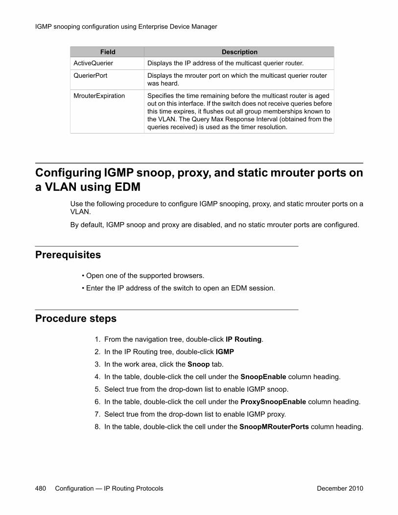
Field DescriptionActiveQuerier Displays the IP address of the multicast querier router.
QuerierPort Displays the mrouter port on which the multicast querier routerwas heard.
MrouterExpiration Specifies the time remaining before the multicast router is agedout on this interface. If the switch does not receive queries beforethis time expires, it flushes out all group memberships known tothe VLAN. The Query Max Response Interval (obtained from thequeries received) is used as the timer resolution.
Configuring IGMP snoop, proxy, and static mrouter ports ona VLAN using EDM
Use the following procedure to configure IGMP snooping, proxy, and static mrouter ports on aVLAN.
By default, IGMP snoop and proxy are disabled, and no static mrouter ports are configured.
Prerequisites
• Open one of the supported browsers.
• Enter the IP address of the switch to open an EDM session.
Procedure steps
1. From the navigation tree, double-click IP Routing.
2. In the IP Routing tree, double-click IGMP
3. In the work area, click the Snoop tab.
4. In the table, double-click the cell under the SnoopEnable column heading.
5. Select true from the drop-down list to enable IGMP snoop.
6. In the table, double-click the cell under the ProxySnoopEnable column heading.
7. Select true from the drop-down list to enable IGMP proxy.
8. In the table, double-click the cell under the SnoopMRouterPorts column heading.
IGMP snooping configuration using Enterprise Device Manager
480 Configuration — IP Routing Protocols December 2010
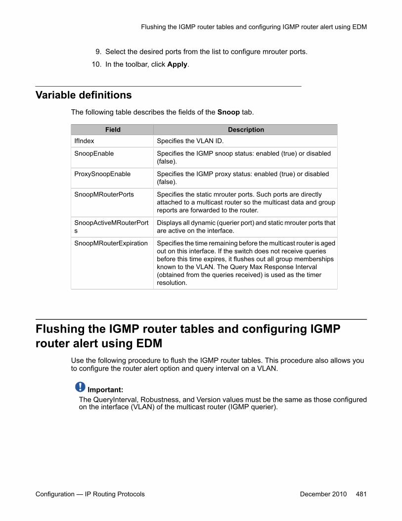
9. Select the desired ports from the list to configure mrouter ports.
10. In the toolbar, click Apply.
Variable definitionsThe following table describes the fields of the Snoop tab.
Field DescriptionIfIndex Specifies the VLAN ID.
SnoopEnable Specifies the IGMP snoop status: enabled (true) or disabled(false).
ProxySnoopEnable Specifies the IGMP proxy status: enabled (true) or disabled(false).
SnoopMRouterPorts Specifies the static mrouter ports. Such ports are directlyattached to a multicast router so the multicast data and groupreports are forwarded to the router.
SnoopActiveMRouterPorts
Displays all dynamic (querier port) and static mrouter ports thatare active on the interface.
SnoopMRouterExpiration Specifies the time remaining before the multicast router is agedout on this interface. If the switch does not receive queriesbefore this time expires, it flushes out all group membershipsknown to the VLAN. The Query Max Response Interval(obtained from the queries received) is used as the timerresolution.
Flushing the IGMP router tables and configuring IGMProuter alert using EDM
Use the following procedure to flush the IGMP router tables. This procedure also allows youto configure the router alert option and query interval on a VLAN.
Important:The QueryInterval, Robustness, and Version values must be the same as those configuredon the interface (VLAN) of the multicast router (IGMP querier).
Flushing the IGMP router tables and configuring IGMP router alert using EDM
Configuration — IP Routing Protocols December 2010 481
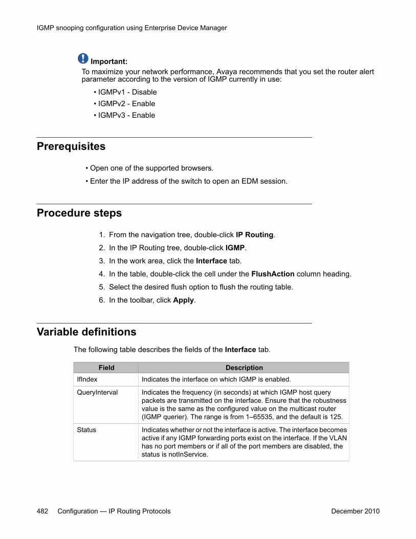
Important:To maximize your network performance, Avaya recommends that you set the router alertparameter according to the version of IGMP currently in use:
• IGMPv1 - Disable• IGMPv2 - Enable• IGMPv3 - Enable
Prerequisites
• Open one of the supported browsers.
• Enter the IP address of the switch to open an EDM session.
Procedure steps
1. From the navigation tree, double-click IP Routing.
2. In the IP Routing tree, double-click IGMP.
3. In the work area, click the Interface tab.
4. In the table, double-click the cell under the FlushAction column heading.
5. Select the desired flush option to flush the routing table.
6. In the toolbar, click Apply.
Variable definitionsThe following table describes the fields of the Interface tab.
Field DescriptionIfIndex Indicates the interface on which IGMP is enabled.
QueryInterval Indicates the frequency (in seconds) at which IGMP host querypackets are transmitted on the interface. Ensure that the robustnessvalue is the same as the configured value on the multicast router(IGMP querier). The range is from 1–65535, and the default is 125.
Status Indicates whether or not the interface is active. The interface becomesactive if any IGMP forwarding ports exist on the interface. If the VLANhas no port members or if all of the port members are disabled, thestatus is notInService.
IGMP snooping configuration using Enterprise Device Manager
482 Configuration — IP Routing Protocols December 2010
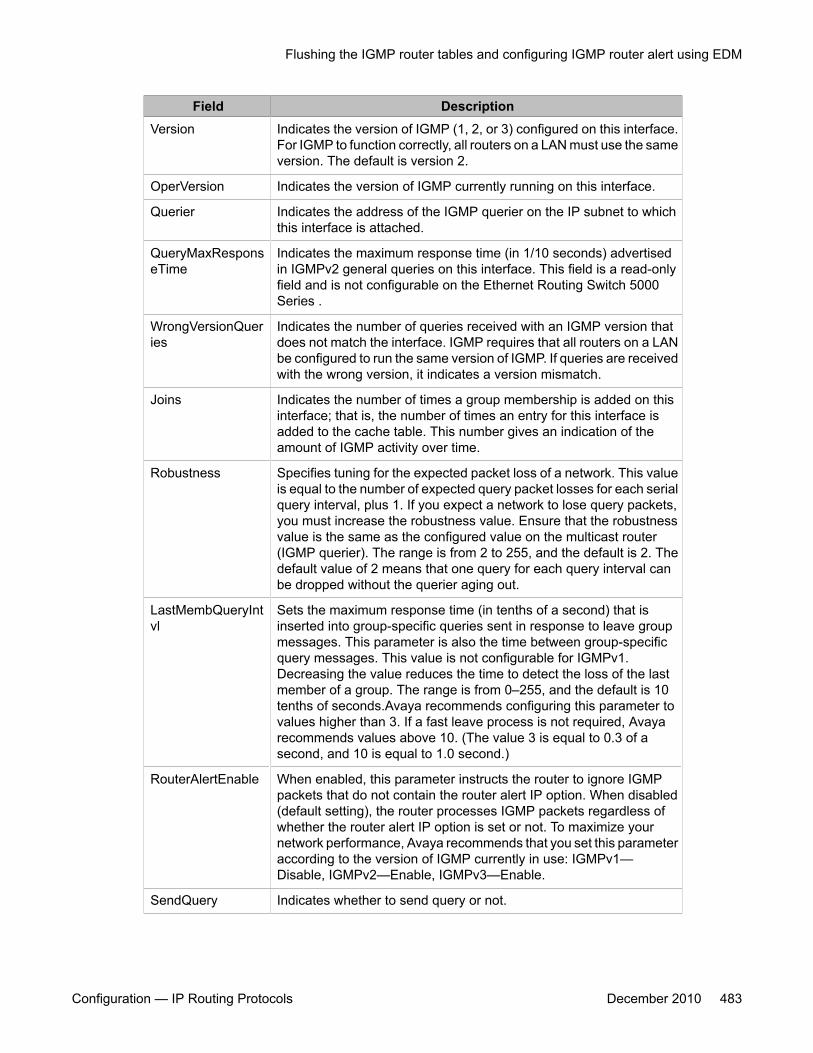
Field DescriptionVersion Indicates the version of IGMP (1, 2, or 3) configured on this interface.
For IGMP to function correctly, all routers on a LAN must use the sameversion. The default is version 2.
OperVersion Indicates the version of IGMP currently running on this interface.
Querier Indicates the address of the IGMP querier on the IP subnet to whichthis interface is attached.
QueryMaxResponseTime
Indicates the maximum response time (in 1/10 seconds) advertisedin IGMPv2 general queries on this interface. This field is a read-onlyfield and is not configurable on the Ethernet Routing Switch 5000Series .
WrongVersionQueries
Indicates the number of queries received with an IGMP version thatdoes not match the interface. IGMP requires that all routers on a LANbe configured to run the same version of IGMP. If queries are receivedwith the wrong version, it indicates a version mismatch.
Joins Indicates the number of times a group membership is added on thisinterface; that is, the number of times an entry for this interface isadded to the cache table. This number gives an indication of theamount of IGMP activity over time.
Robustness Specifies tuning for the expected packet loss of a network. This valueis equal to the number of expected query packet losses for each serialquery interval, plus 1. If you expect a network to lose query packets,you must increase the robustness value. Ensure that the robustnessvalue is the same as the configured value on the multicast router(IGMP querier). The range is from 2 to 255, and the default is 2. Thedefault value of 2 means that one query for each query interval canbe dropped without the querier aging out.
LastMembQueryIntvl
Sets the maximum response time (in tenths of a second) that isinserted into group-specific queries sent in response to leave groupmessages. This parameter is also the time between group-specificquery messages. This value is not configurable for IGMPv1.Decreasing the value reduces the time to detect the loss of the lastmember of a group. The range is from 0–255, and the default is 10tenths of seconds.Avaya recommends configuring this parameter tovalues higher than 3. If a fast leave process is not required, Avayarecommends values above 10. (The value 3 is equal to 0.3 of asecond, and 10 is equal to 1.0 second.)
RouterAlertEnable When enabled, this parameter instructs the router to ignore IGMPpackets that do not contain the router alert IP option. When disabled(default setting), the router processes IGMP packets regardless ofwhether the router alert IP option is set or not. To maximize yournetwork performance, Avaya recommends that you set this parameteraccording to the version of IGMP currently in use: IGMPv1—Disable, IGMPv2—Enable, IGMPv3—Enable.
SendQuery Indicates whether to send query or not.
Flushing the IGMP router tables and configuring IGMP router alert using EDM
Configuration — IP Routing Protocols December 2010 483
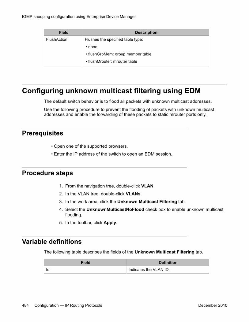
Field DescriptionFlushAction Flushes the specified table type:
• none
• flushGrpMem: group member table
• flushMrouter: mrouter table
Configuring unknown multicast filtering using EDMThe default switch behavior is to flood all packets with unknown multicast addresses.
Use the following procedure to prevent the flooding of packets with unknown multicastaddresses and enable the forwarding of these packets to static mrouter ports only.
Prerequisites
• Open one of the supported browsers.
• Enter the IP address of the switch to open an EDM session.
Procedure steps
1. From the navigation tree, double-click VLAN.
2. In the VLAN tree, double-click VLANs.
3. In the work area, click the Unknown Multicast Filtering tab.
4. Select the UnknownMulticastNoFlood check box to enable unknown multicastflooding.
5. In the toolbar, click Apply.
Variable definitionsThe following table describes the fields of the Unknown Multicast Filtering tab.
Field DefinitionId Indicates the VLAN ID.
IGMP snooping configuration using Enterprise Device Manager
484 Configuration — IP Routing Protocols December 2010

Field DefinitionUnknownMulticastNoFlood Enables or disables unknown multicast
flooding.
Specifying a multicast MAC address to be allowed to floodall VLANs using EDM
Use the following procedure to allow particular unknown multicast packets to be flooded on allswitch VLANs.
Prerequisites
• Open one of the supported browsers.
• Enter the IP address of the switch to open an EDM session.
Procedure steps
1. From the navigation tree, double-click VLAN.
2. In the VLAN tree, double-click VLANs.
3. In the work area, click the MAC Multicast Filter Table tab.
4. In the toolbar, click Insert.
5. Type the VLAN ID to flood in the AllowedAddressVLANId field.
6. Type the MAC address to flood in the AllowedAddressMacAddr field.
7. Click Insert.
Variable definitionsThe following table describes the fields of the MAC Multicast Filter Table tab.
Field DefinitionAllowedAddressVLANId Indicates the allowed VLAN ID.
AllowedAddressMacAddr Indicates the allowed MAC address.
Specifying a multicast MAC address to be allowed to flood all VLANs using EDM
Configuration — IP Routing Protocols December 2010 485

Specifying an IP address to be allowed to flood a VLANusing EDM
Use this procedure to configure the IP address multicast filter table. This table specifiesmulticast IP addresses that are allowed to be flooded to all ports on a per-VLAN basis.
Prerequisites
• Open one of the supported browsers.
• Enter the IP address of the switch to open an EDM session.
Procedure steps
1. From the navigation tree, double-click VLAN.
2. In the VLAN tree, double-click VLANs.
3. In the work area, click the IP Address Multicast Filter Table tab.
4. Click Insert
5. Complete the fields as required.
6. Click Insert
Variable definitionsThe following table describes the fields of the IP Address Multicast Filter Table tab.
Field DefinitionVlanAllowedInetAddressVlanId
Specifies the ID of the VLAN to configure.
VlanAllowedInetAddressType
Specifies the address type: ipv4.
VlanAllowedInetAddress Specifies a multicast IP address that is allowed to flood allports. Unicast and broadcast addresses are not allowed.
IGMP snooping configuration using Enterprise Device Manager
486 Configuration — IP Routing Protocols December 2010

Displaying IGMP cache information using EDMUse the following procedure to display IGMP cache information to show the learned multicastgroups in the cache and the IGMPv1 version timers.
Prerequisites
• Open one of the supported browsers.
• Enter the IP address of the switch to open an EDM session.
Procedure steps
1. From the navigation tree, double-click IP Routing.
2. In the IP Routing tree, double-click IGMP.
3. In the work area, click the Cache tab to view the IGMP cache information.
Variable definitionsThe following table describes the fields of the Cache tab.
Field DescriptionAddress Indicates the IP multicast group address.
IfIndex Indicates the VLAN interface from which thegroup address is heard.
LastReporter Indicates the last IGMP host to join the group.
ExpiryTime Indicates the amount of time (in seconds)remaining before this entry is aged out.
Version1Host Timer Indicates the time remaining until the localrouter assumes that no IGMP version 1members exist on the IP subnet attached tothe interface. Upon hearing an IGMPv1membership report, this value is reset to thegroup membership timer. When the timeremaining is nonzero, the local interface
Displaying IGMP cache information using EDM
Configuration — IP Routing Protocols December 2010 487

Field Descriptionignores IGMPv2 Leave messages that itreceives for this group.
Type Indicates whether the entry is learneddynamically or is added statically.
Displaying IGMP group information using EDMUse the following procedure to display IGMP group information to show the learned multicastgroups and the attached ports.
Prerequisites
• Open one of the supported browsers.
• Enter the IP address of the switch to open an EDM session.
Procedure steps
1. From the navigation tree, double-click IP Routing.
2. In the IP Routing tree, double-click IGMP.
3. In the work area, click the Groups tab.
Variable definitionsThe following table describes the fields of the Groups tab.
Field DescriptionIpAddress Indicates the multicast group address.
IfIndex Indicates the VLAN interface from which the multicast groupaddress is heard.
Members Indicates the IP address of the IGMP receiver (host or IGMPreporter).
Expiration Indicates the time left before the group report expires on thisport. This variable is updated upon receiving a group report.
IGMP snooping configuration using Enterprise Device Manager
488 Configuration — IP Routing Protocols December 2010
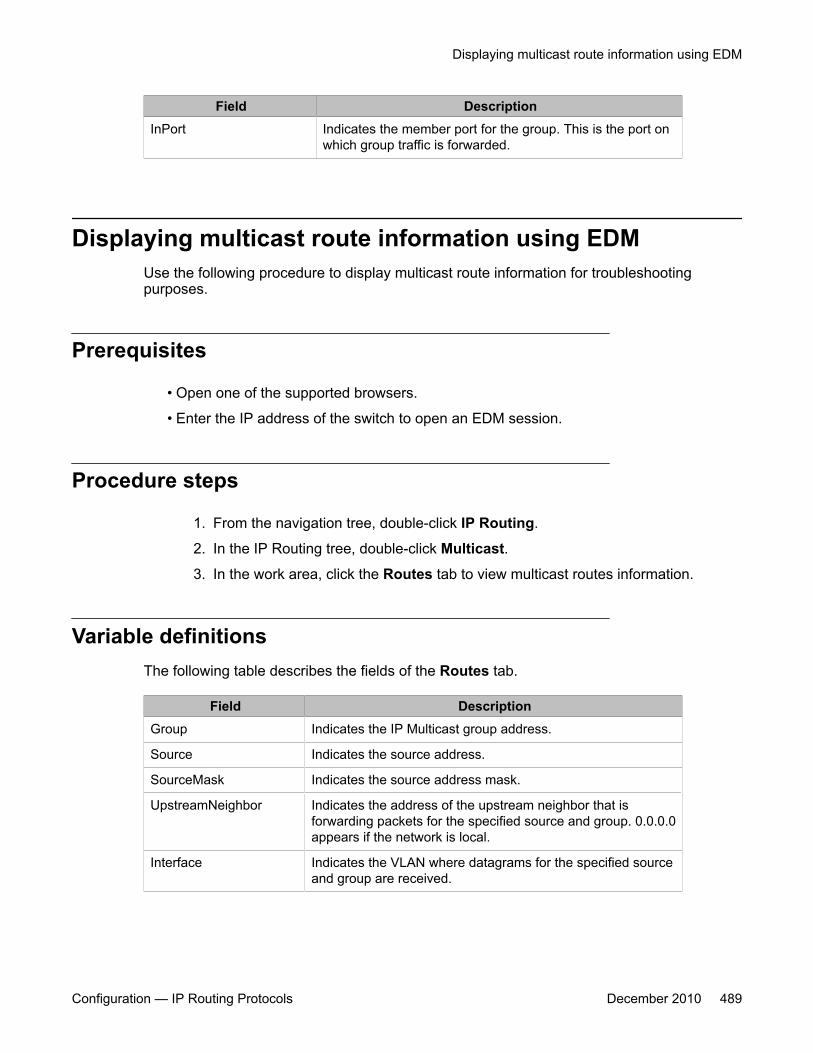
Field DescriptionInPort Indicates the member port for the group. This is the port on
which group traffic is forwarded.
Displaying multicast route information using EDMUse the following procedure to display multicast route information for troubleshootingpurposes.
Prerequisites
• Open one of the supported browsers.
• Enter the IP address of the switch to open an EDM session.
Procedure steps
1. From the navigation tree, double-click IP Routing.
2. In the IP Routing tree, double-click Multicast.
3. In the work area, click the Routes tab to view multicast routes information.
Variable definitionsThe following table describes the fields of the Routes tab.
Field DescriptionGroup Indicates the IP Multicast group address.
Source Indicates the source address.
SourceMask Indicates the source address mask.
UpstreamNeighbor Indicates the address of the upstream neighbor that isforwarding packets for the specified source and group. 0.0.0.0appears if the network is local.
Interface Indicates the VLAN where datagrams for the specified sourceand group are received.
Displaying multicast route information using EDM
Configuration — IP Routing Protocols December 2010 489
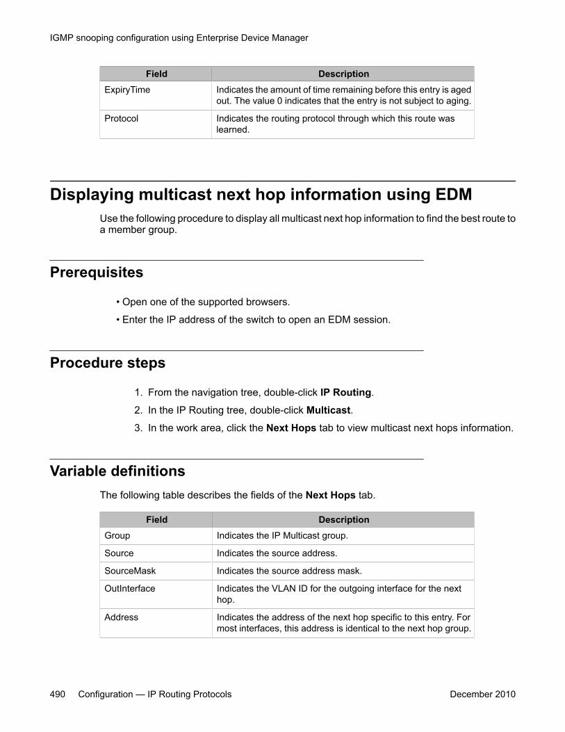
Field DescriptionExpiryTime Indicates the amount of time remaining before this entry is aged
out. The value 0 indicates that the entry is not subject to aging.
Protocol Indicates the routing protocol through which this route waslearned.
Displaying multicast next hop information using EDMUse the following procedure to display all multicast next hop information to find the best route toa member group.
Prerequisites
• Open one of the supported browsers.
• Enter the IP address of the switch to open an EDM session.
Procedure steps
1. From the navigation tree, double-click IP Routing.
2. In the IP Routing tree, double-click Multicast.
3. In the work area, click the Next Hops tab to view multicast next hops information.
Variable definitionsThe following table describes the fields of the Next Hops tab.
Field DescriptionGroup Indicates the IP Multicast group.
Source Indicates the source address.
SourceMask Indicates the source address mask.
OutInterface Indicates the VLAN ID for the outgoing interface for the nexthop.
Address Indicates the address of the next hop specific to this entry. Formost interfaces, this address is identical to the next hop group.
IGMP snooping configuration using Enterprise Device Manager
490 Configuration — IP Routing Protocols December 2010

Field DescriptionState Indicates whether or not the outgoing interface and next hop
represented by this entry is currently being used to forward IPdatagrams. A Value of forwarding indicates this parameter iscurrently being used; pruned indicates the parameter is notbeing used.
ExpiryTime Indicates the amount of time remaining before this entry is agedout. The value 0 indicates that the entry is not subject to aging.
ClosestMemberHops Indicates the minimum number of hops between this router anda member of this IP Multicast group reached through this nexthop on this outgoing interface. IP Multicast datagrams for thegroup that have a TTL less than this number of hops are notforwarded to the next hop.
Protocol Indicates the routing protocol where this next hop was learned.
Displaying multicast interface information using EDMUse the following procedure to display multicast interface information.
Prerequisites
• Open one of the supported browsers.
• Enter the IP address of the switch to open an EDM session.
Procedure steps
1. From the navigation tree, double-click IP Routing.
2. In the IP Routing tree, double-click Multicast.
3. In the work area, click the Interfaces tab to view multicast interfaces information.
Variable definitionsThe following table describes the fields of the Interfaces tab.
Displaying multicast interface information using EDM
Configuration — IP Routing Protocols December 2010 491
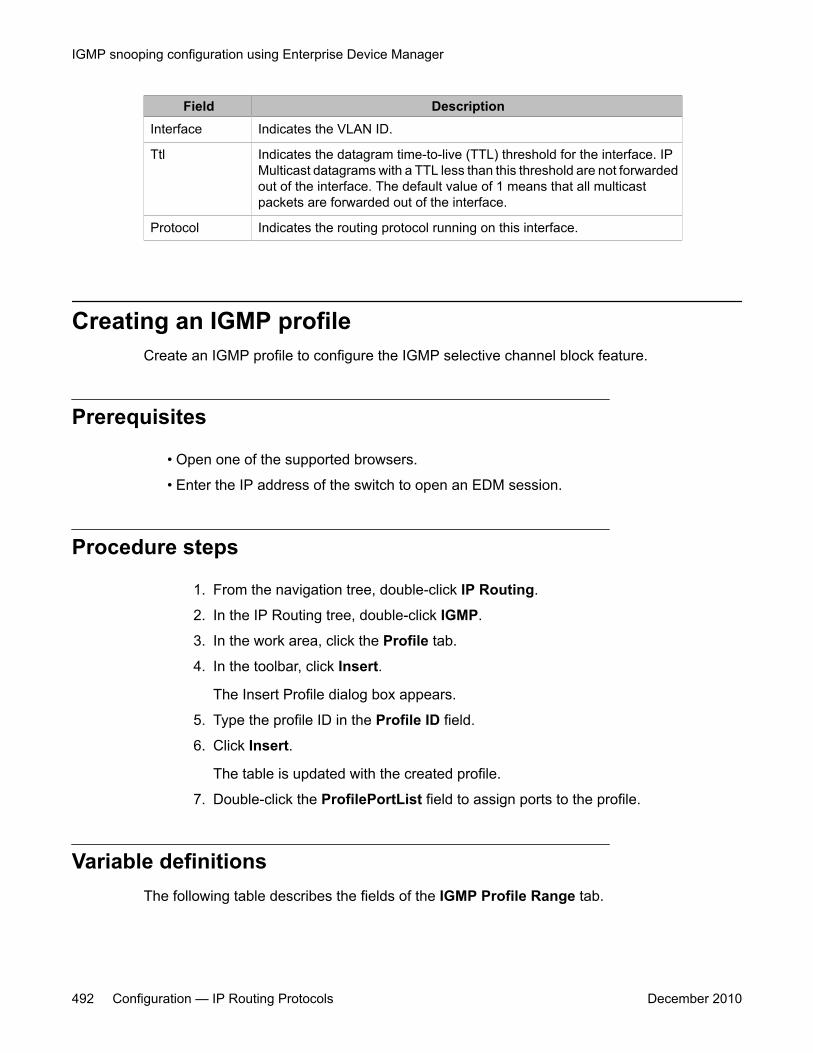
Field DescriptionInterface Indicates the VLAN ID.
Ttl Indicates the datagram time-to-live (TTL) threshold for the interface. IPMulticast datagrams with a TTL less than this threshold are not forwardedout of the interface. The default value of 1 means that all multicastpackets are forwarded out of the interface.
Protocol Indicates the routing protocol running on this interface.
Creating an IGMP profileCreate an IGMP profile to configure the IGMP selective channel block feature.
Prerequisites
• Open one of the supported browsers.
• Enter the IP address of the switch to open an EDM session.
Procedure steps
1. From the navigation tree, double-click IP Routing.
2. In the IP Routing tree, double-click IGMP.
3. In the work area, click the Profile tab.
4. In the toolbar, click Insert.
The Insert Profile dialog box appears.
5. Type the profile ID in the Profile ID field.
6. Click Insert.
The table is updated with the created profile.
7. Double-click the ProfilePortList field to assign ports to the profile.
Variable definitionsThe following table describes the fields of the IGMP Profile Range tab.
IGMP snooping configuration using Enterprise Device Manager
492 Configuration — IP Routing Protocols December 2010
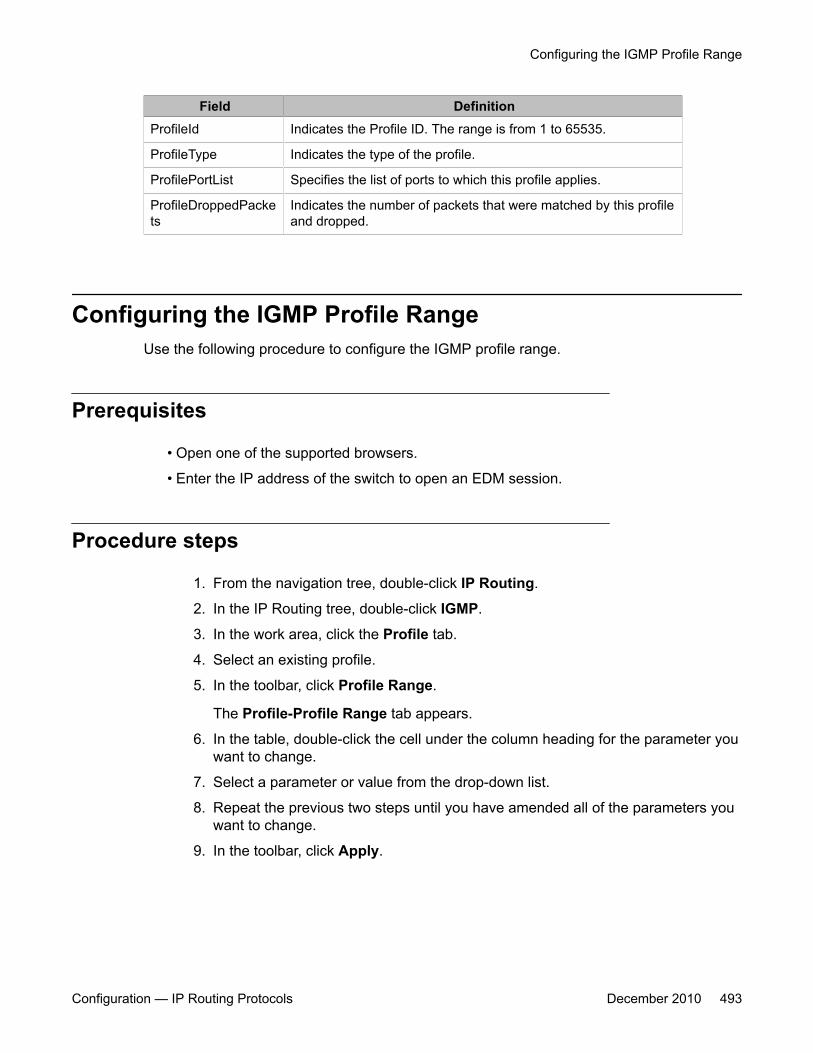
Field DefinitionProfileId Indicates the Profile ID. The range is from 1 to 65535.
ProfileType Indicates the type of the profile.
ProfilePortList Specifies the list of ports to which this profile applies.
ProfileDroppedPackets
Indicates the number of packets that were matched by this profileand dropped.
Configuring the IGMP Profile RangeUse the following procedure to configure the IGMP profile range.
Prerequisites
• Open one of the supported browsers.
• Enter the IP address of the switch to open an EDM session.
Procedure steps
1. From the navigation tree, double-click IP Routing.
2. In the IP Routing tree, double-click IGMP.
3. In the work area, click the Profile tab.
4. Select an existing profile.
5. In the toolbar, click Profile Range.
The Profile-Profile Range tab appears.
6. In the table, double-click the cell under the column heading for the parameter youwant to change.
7. Select a parameter or value from the drop-down list.
8. Repeat the previous two steps until you have amended all of the parameters youwant to change.
9. In the toolbar, click Apply.
Configuring the IGMP Profile Range
Configuration — IP Routing Protocols December 2010 493
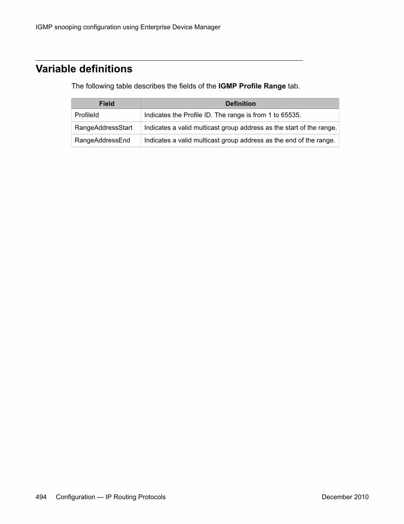
Variable definitionsThe following table describes the fields of the IGMP Profile Range tab.
Field DefinitionProfileId Indicates the Profile ID. The range is from 1 to 65535.
RangeAddressStart Indicates a valid multicast group address as the start of the range.
RangeAddressEnd Indicates a valid multicast group address as the end of the range.
IGMP snooping configuration using Enterprise Device Manager
494 Configuration — IP Routing Protocols December 2010
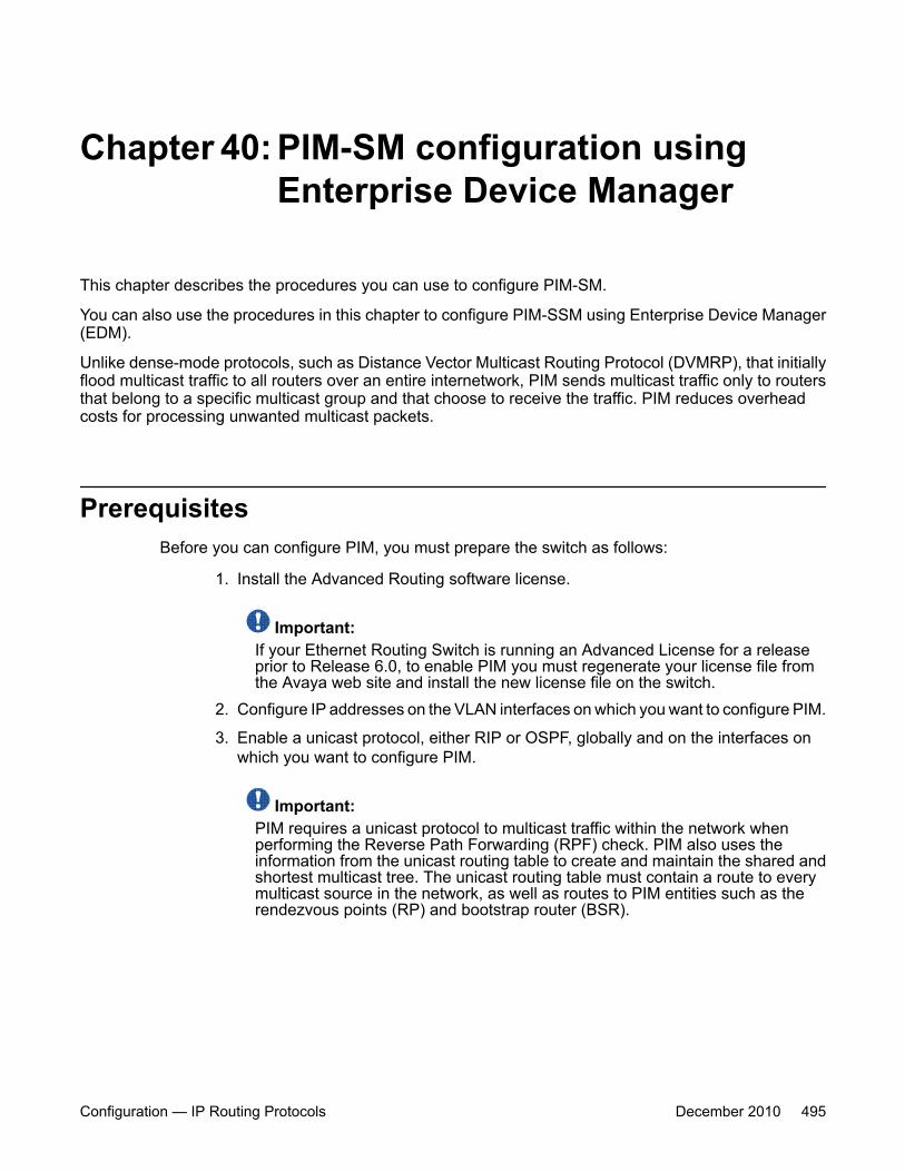
Chapter 40: PIM-SM configuration usingEnterprise Device Manager
This chapter describes the procedures you can use to configure PIM-SM.
You can also use the procedures in this chapter to configure PIM-SSM using Enterprise Device Manager(EDM).
Unlike dense-mode protocols, such as Distance Vector Multicast Routing Protocol (DVMRP), that initiallyflood multicast traffic to all routers over an entire internetwork, PIM sends multicast traffic only to routersthat belong to a specific multicast group and that choose to receive the traffic. PIM reduces overheadcosts for processing unwanted multicast packets.
PrerequisitesBefore you can configure PIM, you must prepare the switch as follows:
1. Install the Advanced Routing software license.
Important:If your Ethernet Routing Switch is running an Advanced License for a releaseprior to Release 6.0, to enable PIM you must regenerate your license file fromthe Avaya web site and install the new license file on the switch.
2. Configure IP addresses on the VLAN interfaces on which you want to configure PIM.
3. Enable a unicast protocol, either RIP or OSPF, globally and on the interfaces onwhich you want to configure PIM.
Important:PIM requires a unicast protocol to multicast traffic within the network whenperforming the Reverse Path Forwarding (RPF) check. PIM also uses theinformation from the unicast routing table to create and maintain the shared andshortest multicast tree. The unicast routing table must contain a route to everymulticast source in the network, as well as routes to PIM entities such as therendezvous points (RP) and bootstrap router (BSR).
Configuration — IP Routing Protocols December 2010 495
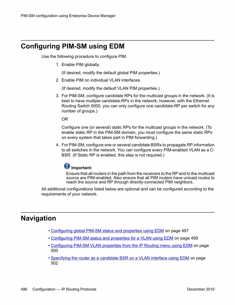
Configuring PIM-SM using EDMUse the following procedure to configure PIM.
1. Enable PIM globally.
(If desired, modify the default global PIM properties.)
2. Enable PIM on individual VLAN interfaces.
(If desired, modify the default VLAN PIM properties.)
3. For PIM-SM, configure candidate RPs for the multicast groups in the network. (It isbest to have multiple candidate-RPs in the network; however, with the EthernetRouting Switch 5000, you can only configure one candidate-RP per switch for anynumber of groups.)
OR
Configure one (or several) static RPs for the multicast groups in the network. (Toenable static RP in the PIM-SM domain, you must configure the same static RPson every system that takes part in PIM forwarding.)
4. For PIM-SM, configure one or several candidate BSRs to propagate RP informationto all switches in the network. You can configure every PIM-enabled VLAN as a C-BSR. (If Static RP is enabled, this step is not required.)
Important:Ensure that all routers in the path from the receivers to the RP and to the multicastsource are PIM-enabled. Also ensure that all PIM routers have unicast routes toreach the source and RP through directly-connected PIM neighbors.
All additional configurations listed below are optional and can be configured according to therequirements of your network.
Navigation• Configuring global PIM-SM status and properties using EDM on page 497
• Configuring PIM-SM status and properties for a VLAN using EDM on page 499
• Configuring PIM-SM VLAN properties from the IP Routing menu using EDM on page 500
• Specifying the router as a candidate BSR on a VLAN interface using EDM on page 502
PIM-SM configuration using Enterprise Device Manager
496 Configuration — IP Routing Protocols December 2010
• Displaying the current BSR using EDM on page 504
• Specifying a local IP interface as a candidate RP using EDM on page 505
• Displaying the active RP using EDM on page 506
• Configuring a static RP using EDM on page 507
• Specifying a virtual neighbor on an interface using EDM on page 509
• Displaying PIM-SM neighbor parameters using EDM on page 510
• Displaying the PIM-SM RP set using EDM on page 510
• Configuring PIM-SSM globally
• Configuring the SSM channel table
• Configuring the SSM range and global parameters
Configuring global PIM-SM status and properties using EDMUse the following procedure to configure PIM-SM status and properties globally.
Prerequisites
You must enable PIM-SM globally.
Procedure steps
1. From the navigation tree, double-click IP Routing.
2. In the IP Routing tree, double-click PIM.
3. In the Globals tab, select the Enable check box to enable PIM-SM.
4. Configure the other parameters as required.
5. In the toolbar, click Apply.
Configuring global PIM-SM status and properties using EDM
Configuration — IP Routing Protocols December 2010 497
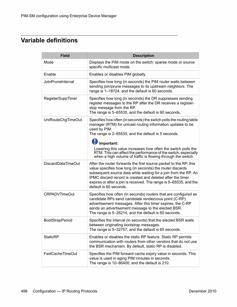
Variable definitions
Field DescriptionMode Displays the PIM mode on the switch: sparse mode or source
specific multicast mode.
Enable Enables or disables PIM globally.
JoinPruneInterval Specifies how long (in seconds) the PIM router waits betweensending join/prune messages to its upstream neighbors. Therange is 1–18724, and the default is 60 seconds.
RegisterSuppTimer Specifies how long (in seconds) the DR suppresses sendingregister messages to the RP after the DR receives a register-stop message from the RP.The range is 5–65535, and the default is 60 seconds.
UniRouteChgTimeOut Specifies how often (in seconds) the switch polls the routing tablemanager (RTM) for unicast routing information updates to beused by PIM.The range is 2–65535, and the default is 5 seconds.
Important:Lowering this value increases how often the switch polls theRTM. This can affect the performance of the switch, especiallywhen a high volume of traffic is flowing through the switch.
DiscardDataTimeOut After the router forwards the first source packet to the RP, thisvalue specifies how long (in seconds) the router discardssubsequent source data while waiting for a join from the RP. AnIPMC discard record is created and deleted after the timerexpires or after a join is received. The range is 5–65535, and thedefault is 60 seconds.
CRPADVTimeOut Specifies how often (in seconds) routers that are configured ascandidate RPs send candidate rendezvous point (C-RP)advertisement messages. After this timer expires, the C-RPsends an advertisement message to the elected BSR.The range is 5–26214, and the default is 60 seconds.
BootStrapPeriod Specifies the interval (in seconds) that the elected BSR waitsbetween originating bootstrap messages.The range is 5–32757, and the default is 60 seconds.
StaticRP Enables or disables the static RP feature. Static RP permitscommunication with routers from other vendors that do not usethe BSR mechanism. By default, static RP is disabled.
FwdCacheTimeOut Specifies the PIM forward cache expiry value in seconds. Thisvalue is used in aging PIM mroutes in seconds.The range is 10–86400, and the default is 210.
PIM-SM configuration using Enterprise Device Manager
498 Configuration — IP Routing Protocols December 2010
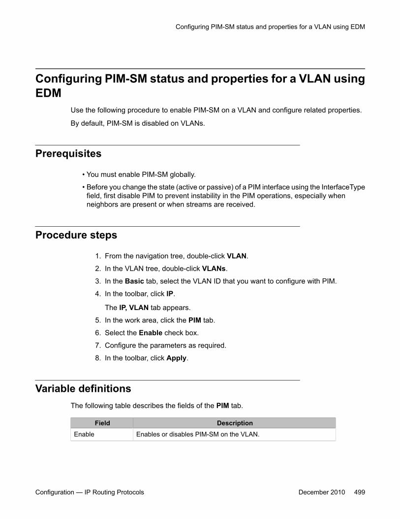
Configuring PIM-SM status and properties for a VLAN usingEDM
Use the following procedure to enable PIM-SM on a VLAN and configure related properties.
By default, PIM-SM is disabled on VLANs.
Prerequisites
• You must enable PIM-SM globally.
• Before you change the state (active or passive) of a PIM interface using the InterfaceTypefield, first disable PIM to prevent instability in the PIM operations, especially whenneighbors are present or when streams are received.
Procedure steps
1. From the navigation tree, double-click VLAN.
2. In the VLAN tree, double-click VLANs.
3. In the Basic tab, select the VLAN ID that you want to configure with PIM.
4. In the toolbar, click IP.
The IP, VLAN tab appears.
5. In the work area, click the PIM tab.
6. Select the Enable check box.
7. Configure the parameters as required.
8. In the toolbar, click Apply.
Variable definitionsThe following table describes the fields of the PIM tab.
Field DescriptionEnable Enables or disables PIM-SM on the VLAN.
Configuring PIM-SM status and properties for a VLAN using EDM
Configuration — IP Routing Protocols December 2010 499
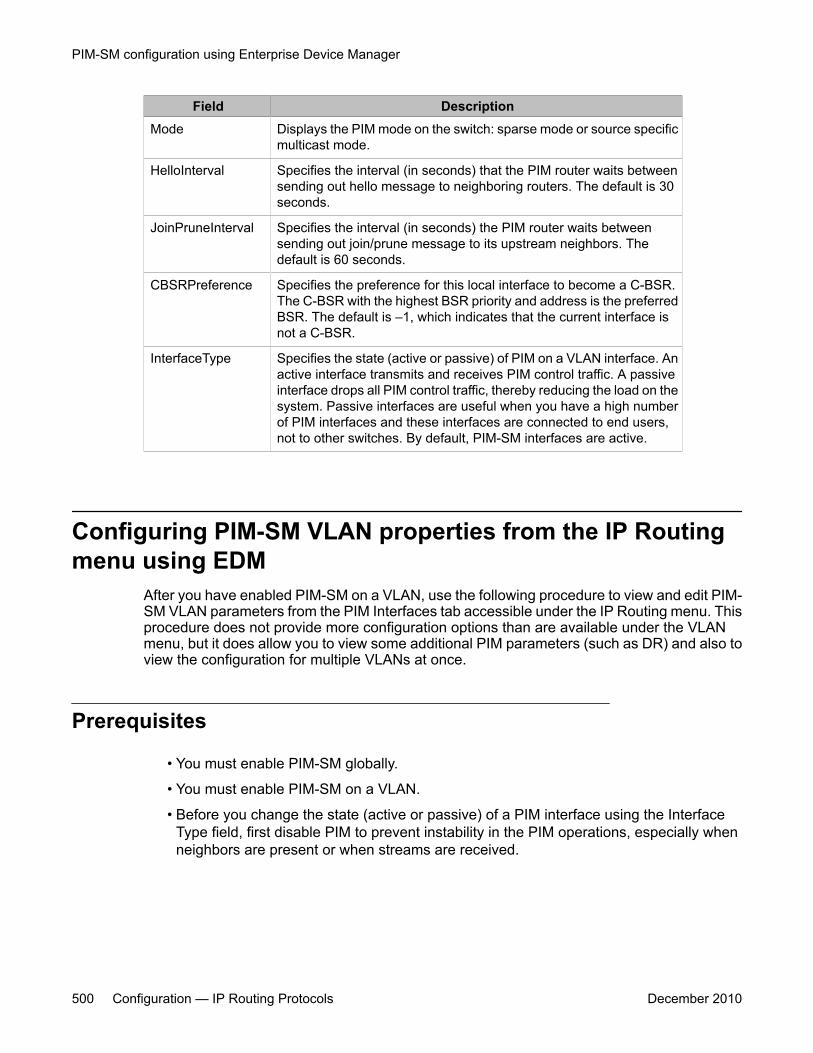
Field DescriptionMode Displays the PIM mode on the switch: sparse mode or source specific
multicast mode.
HelloInterval Specifies the interval (in seconds) that the PIM router waits betweensending out hello message to neighboring routers. The default is 30seconds.
JoinPruneInterval Specifies the interval (in seconds) the PIM router waits betweensending out join/prune message to its upstream neighbors. Thedefault is 60 seconds.
CBSRPreference Specifies the preference for this local interface to become a C-BSR.The C-BSR with the highest BSR priority and address is the preferredBSR. The default is –1, which indicates that the current interface isnot a C-BSR.
InterfaceType Specifies the state (active or passive) of PIM on a VLAN interface. Anactive interface transmits and receives PIM control traffic. A passiveinterface drops all PIM control traffic, thereby reducing the load on thesystem. Passive interfaces are useful when you have a high numberof PIM interfaces and these interfaces are connected to end users,not to other switches. By default, PIM-SM interfaces are active.
Configuring PIM-SM VLAN properties from the IP Routingmenu using EDM
After you have enabled PIM-SM on a VLAN, use the following procedure to view and edit PIM-SM VLAN parameters from the PIM Interfaces tab accessible under the IP Routing menu. Thisprocedure does not provide more configuration options than are available under the VLANmenu, but it does allow you to view some additional PIM parameters (such as DR) and also toview the configuration for multiple VLANs at once.
Prerequisites
• You must enable PIM-SM globally.
• You must enable PIM-SM on a VLAN.
• Before you change the state (active or passive) of a PIM interface using the InterfaceType field, first disable PIM to prevent instability in the PIM operations, especially whenneighbors are present or when streams are received.
PIM-SM configuration using Enterprise Device Manager
500 Configuration — IP Routing Protocols December 2010
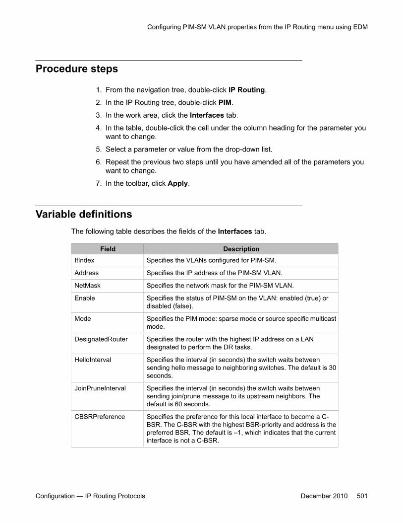
Procedure steps
1. From the navigation tree, double-click IP Routing.
2. In the IP Routing tree, double-click PIM.
3. In the work area, click the Interfaces tab.
4. In the table, double-click the cell under the column heading for the parameter youwant to change.
5. Select a parameter or value from the drop-down list.
6. Repeat the previous two steps until you have amended all of the parameters youwant to change.
7. In the toolbar, click Apply.
Variable definitionsThe following table describes the fields of the Interfaces tab.
Field DescriptionIfIndex Specifies the VLANs configured for PIM-SM.
Address Specifies the IP address of the PIM-SM VLAN.
NetMask Specifies the network mask for the PIM-SM VLAN.
Enable Specifies the status of PIM-SM on the VLAN: enabled (true) ordisabled (false).
Mode Specifies the PIM mode: sparse mode or source specific multicastmode.
DesignatedRouter Specifies the router with the highest IP address on a LANdesignated to perform the DR tasks.
HelloInterval Specifies the interval (in seconds) the switch waits betweensending hello message to neighboring switches. The default is 30seconds.
JoinPruneInterval Specifies the interval (in seconds) the switch waits betweensending join/prune message to its upstream neighbors. Thedefault is 60 seconds.
CBSRPreference Specifies the preference for this local interface to become a C-BSR. The C-BSR with the highest BSR-priority and address is thepreferred BSR. The default is –1, which indicates that the currentinterface is not a C-BSR.
Configuring PIM-SM VLAN properties from the IP Routing menu using EDM
Configuration — IP Routing Protocols December 2010 501
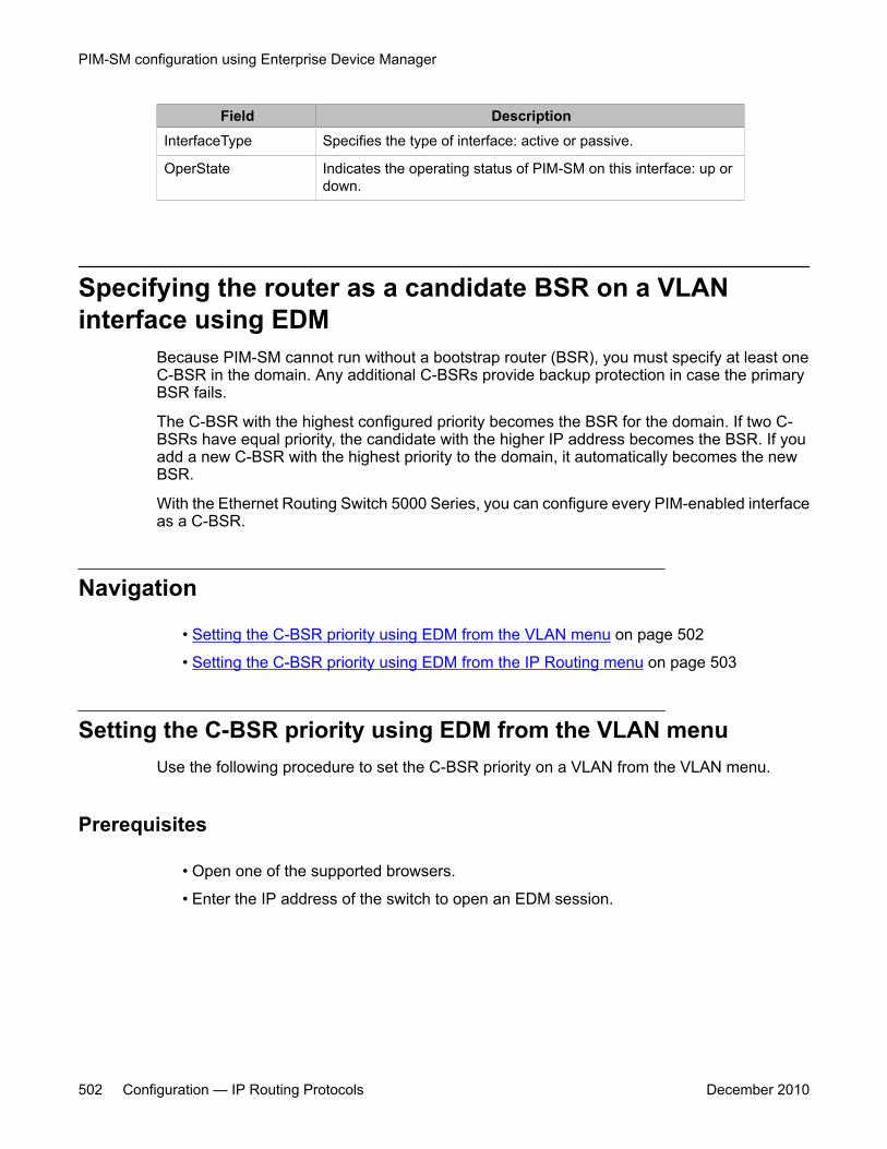
Field DescriptionInterfaceType Specifies the type of interface: active or passive.
OperState Indicates the operating status of PIM-SM on this interface: up ordown.
Specifying the router as a candidate BSR on a VLANinterface using EDM
Because PIM-SM cannot run without a bootstrap router (BSR), you must specify at least oneC-BSR in the domain. Any additional C-BSRs provide backup protection in case the primaryBSR fails.
The C-BSR with the highest configured priority becomes the BSR for the domain. If two C-BSRs have equal priority, the candidate with the higher IP address becomes the BSR. If youadd a new C-BSR with the highest priority to the domain, it automatically becomes the newBSR.
With the Ethernet Routing Switch 5000 Series, you can configure every PIM-enabled interfaceas a C-BSR.
Navigation
• Setting the C-BSR priority using EDM from the VLAN menu on page 502
• Setting the C-BSR priority using EDM from the IP Routing menu on page 503
Setting the C-BSR priority using EDM from the VLAN menuUse the following procedure to set the C-BSR priority on a VLAN from the VLAN menu.
Prerequisites
• Open one of the supported browsers.
• Enter the IP address of the switch to open an EDM session.
PIM-SM configuration using Enterprise Device Manager
502 Configuration — IP Routing Protocols December 2010
Procedure steps
1. From the navigation tree, double-click VLAN.
2. In the VLAN tree, double-click VLANs.
3. In the Basic tab, select the VLAN ID that you want to configure with PIM.
4. In the toolbar, click IP.
The IP, VLAN tab appears.
5. In the work area, click the PIM tab.
6. In the CBSRPreference field, type the value of the C-BSR priority.
7. In the toolbar, click Apply.
Setting the C-BSR priority using EDM from the IP Routing menuUse the following procedure to set the C-BSR priority on a VLAN from the IP Routing menu.
Prerequisites
• Open one of the supported browsers.
• Enter the IP address of the switch to open an EDM session.
Procedure steps
1. From the navigation tree, double-click IP Routing.
2. In the IP Routing tree, double-click PIM.
3. In the work area, click the Interfaces tab.
4. In the table, double-click the cell under the CBSRPreference column heading forthe parameter you want to change.
5. Type the value of the C-BSR priority for the associated interface.
The Candidate BSR with the highest BSR-priority and address is the preferred BSR.The default is –1, which indicates that the current interface is not a Candidate BSR;the range is 0 to 255.
6. In the toolbar, click Apply.
Specifying the router as a candidate BSR on a VLAN interface using EDM
Configuration — IP Routing Protocols December 2010 503
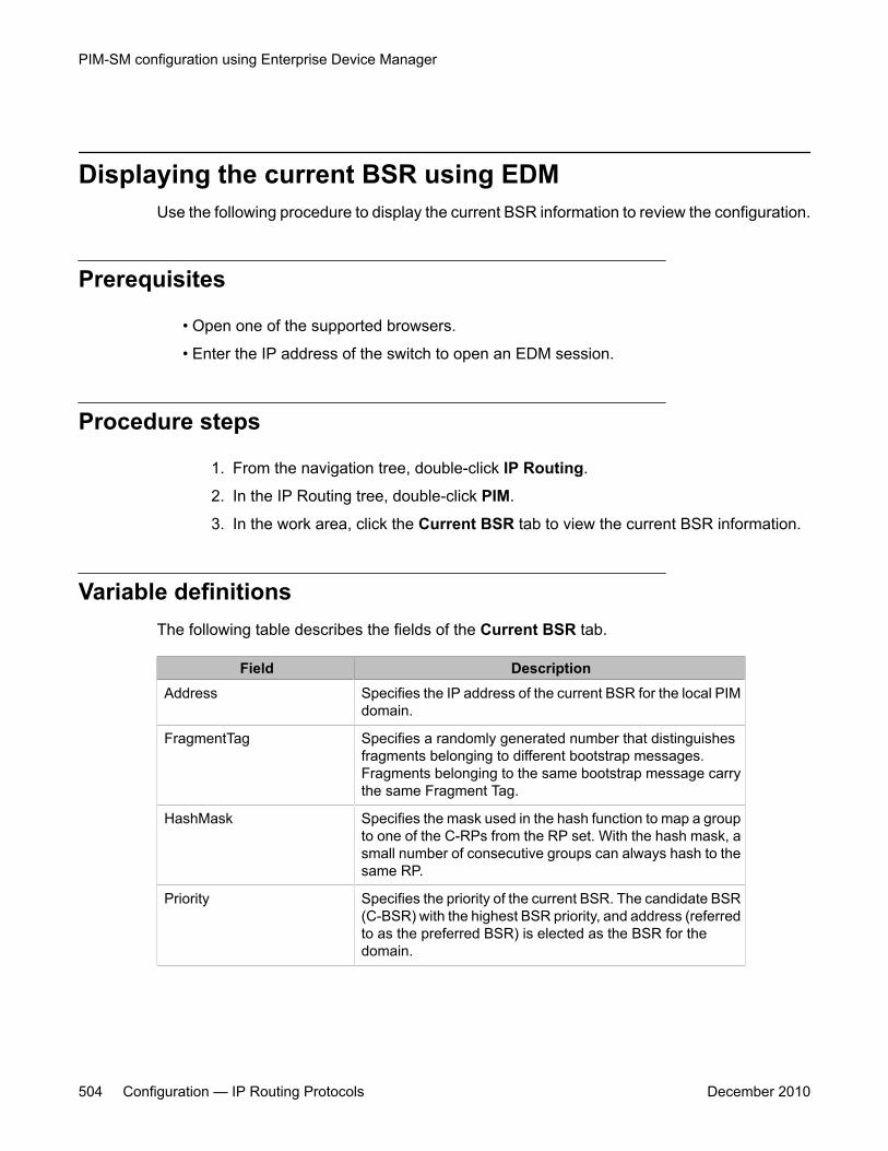
Displaying the current BSR using EDMUse the following procedure to display the current BSR information to review the configuration.
Prerequisites
• Open one of the supported browsers.
• Enter the IP address of the switch to open an EDM session.
Procedure steps
1. From the navigation tree, double-click IP Routing.
2. In the IP Routing tree, double-click PIM.
3. In the work area, click the Current BSR tab to view the current BSR information.
Variable definitionsThe following table describes the fields of the Current BSR tab.
Field DescriptionAddress Specifies the IP address of the current BSR for the local PIM
domain.
FragmentTag Specifies a randomly generated number that distinguishesfragments belonging to different bootstrap messages.Fragments belonging to the same bootstrap message carrythe same Fragment Tag.
HashMask Specifies the mask used in the hash function to map a groupto one of the C-RPs from the RP set. With the hash mask, asmall number of consecutive groups can always hash to thesame RP.
Priority Specifies the priority of the current BSR. The candidate BSR(C-BSR) with the highest BSR priority, and address (referredto as the preferred BSR) is elected as the BSR for thedomain.
PIM-SM configuration using Enterprise Device Manager
504 Configuration — IP Routing Protocols December 2010
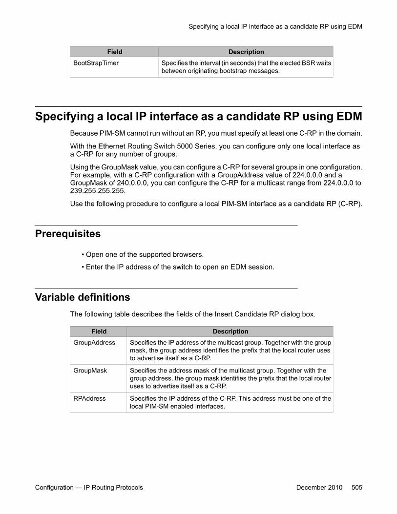
Field DescriptionBootStrapTimer Specifies the interval (in seconds) that the elected BSR waits
between originating bootstrap messages.
Specifying a local IP interface as a candidate RP using EDMBecause PIM-SM cannot run without an RP, you must specify at least one C-RP in the domain.
With the Ethernet Routing Switch 5000 Series, you can configure only one local interface asa C-RP for any number of groups.
Using the GroupMask value, you can configure a C-RP for several groups in one configuration.For example, with a C-RP configuration with a GroupAddress value of 224.0.0.0 and aGroupMask of 240.0.0.0, you can configure the C-RP for a multicast range from 224.0.0.0 to239.255.255.255.
Use the following procedure to configure a local PIM-SM interface as a candidate RP (C-RP).
Prerequisites
• Open one of the supported browsers.
• Enter the IP address of the switch to open an EDM session.
Variable definitionsThe following table describes the fields of the Insert Candidate RP dialog box.
Field DescriptionGroupAddress Specifies the IP address of the multicast group. Together with the group
mask, the group address identifies the prefix that the local router usesto advertise itself as a C-RP.
GroupMask Specifies the address mask of the multicast group. Together with thegroup address, the group mask identifies the prefix that the local routeruses to advertise itself as a C-RP.
RPAddress Specifies the IP address of the C-RP. This address must be one of thelocal PIM-SM enabled interfaces.
Specifying a local IP interface as a candidate RP using EDM
Configuration — IP Routing Protocols December 2010 505
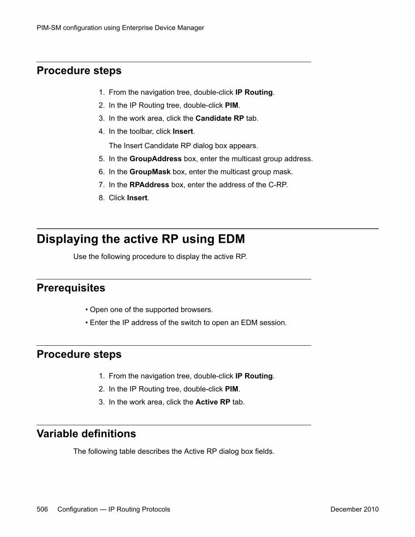
Procedure steps
1. From the navigation tree, double-click IP Routing.
2. In the IP Routing tree, double-click PIM.
3. In the work area, click the Candidate RP tab.
4. In the toolbar, click Insert.
The Insert Candidate RP dialog box appears.
5. In the GroupAddress box, enter the multicast group address.
6. In the GroupMask box, enter the multicast group mask.
7. In the RPAddress box, enter the address of the C-RP.
8. Click Insert.
Displaying the active RP using EDMUse the following procedure to display the active RP.
Prerequisites
• Open one of the supported browsers.
• Enter the IP address of the switch to open an EDM session.
Procedure steps
1. From the navigation tree, double-click IP Routing.
2. In the IP Routing tree, double-click PIM.
3. In the work area, click the Active RP tab.
Variable definitionsThe following table describes the Active RP dialog box fields.
PIM-SM configuration using Enterprise Device Manager
506 Configuration — IP Routing Protocols December 2010

Field DescriptionGroupAddress Specifies the IP address of the multicast group.
GroupMask Specifies the address mask of the multicast group.
ActiveRP Specifies the IP address of the active RP.
Priority Specifies the priority of the active RP.
Configuring a static RP using EDMUse the following procedure to configure a static RP entry. After you configure static RP, theswitch ignores the BSR mechanism and uses the statically-configured RPs only.
Prerequisites
You must enable static RP.
Procedure steps
1. From the navigation tree, double-click IP Routing.
2. In the IP Routing tree, double-click PIM.
3. In the work area, click the Static RP tab.
4. In the toolbar, click Insert.
The Insert Static RP dialog box appears.
5. In the GroupAddress box, type the multicast group address.
6. In the GroupMask box, type the multicast group mask.
7. In the RPAddress box, enter the address of the static RP.
8. Click Insert.
Variable definitionsThe following table describes the fields of the Static RP tab.
Configuring a static RP using EDM
Configuration — IP Routing Protocols December 2010 507

Field DescriptionGroupAddress Specifies the IP address of the multicast group. Together with the group
mask, the IP address identifies the range of the multicast addresses thatthe RP handles.
GroupMask Specifies the address mask of the multicast group. Together with the groupaddress, the address mask identifies the range of the multicast addressesthat the RP handles.
RPAddress Specifies the IP address of the static RP.
Status Shows the current status of the static RP entry. The status is valid whenthe switch has a unicast route to the network for the static RP and is invalidotherwise.
Enabling static RP using EDMEnable static RP to avoid the process of dynamically learning C-RPs through the BSRmechanism. With this feature, static RP-enabled Ethernet Routing Switch 5000 Seriesswitches can communicate with switches from other vendors that do not use the BSRmechanism.
Use the following procedure to enable static RP.
Important:When you enable static RP, all dynamically learned BSR information is lost. However, if youdisable static RP, the switch loses the static RP information and regains the BSRfunctionality.
Procedure steps
1. From the navigation tree, double-click IP Routing.
2. In the IP Routing tree, double-click PIM.
3. In the Globals tab, select the Enable check box to enable PIM-SM globally.
4. Select the StaticRP check box.
5. In the toolbar, click Apply.
PIM-SM configuration using Enterprise Device Manager
508 Configuration — IP Routing Protocols December 2010
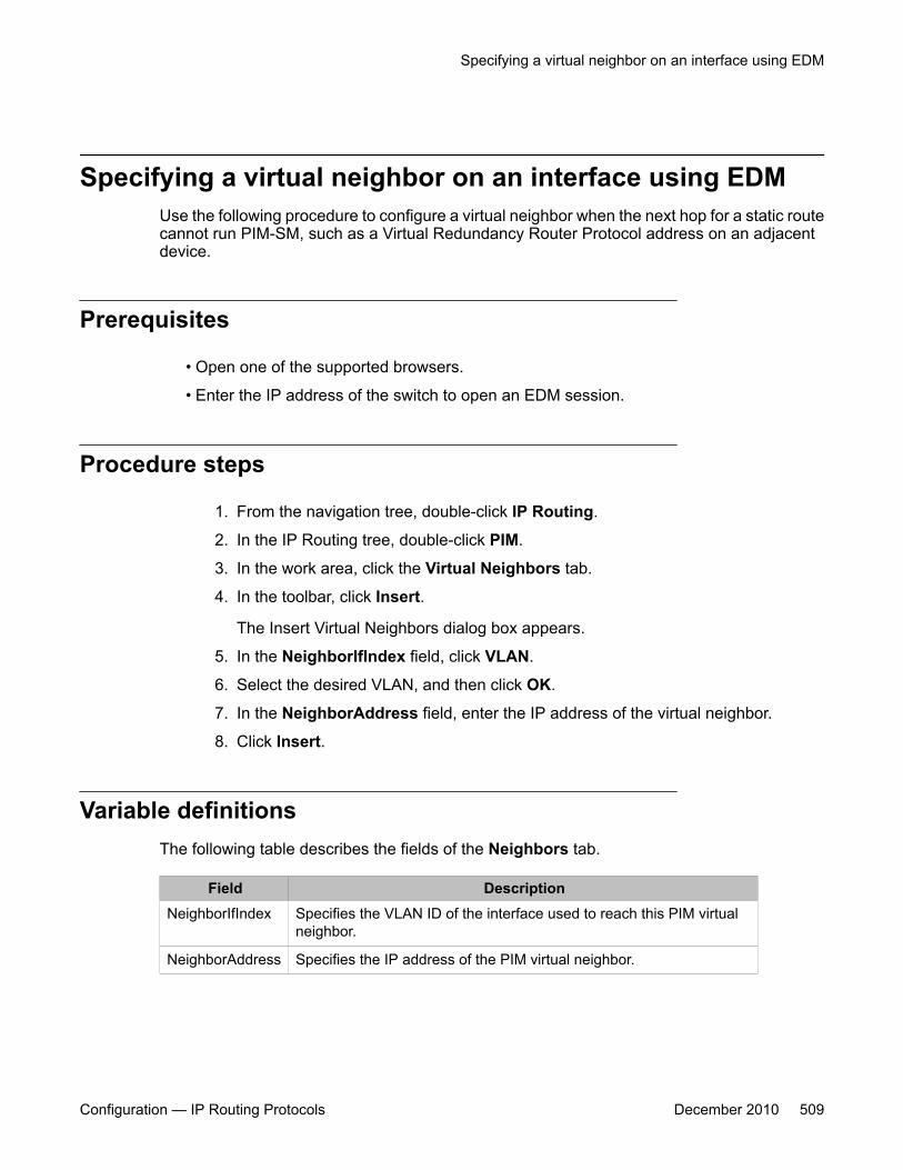
Specifying a virtual neighbor on an interface using EDMUse the following procedure to configure a virtual neighbor when the next hop for a static routecannot run PIM-SM, such as a Virtual Redundancy Router Protocol address on an adjacentdevice.
Prerequisites
• Open one of the supported browsers.
• Enter the IP address of the switch to open an EDM session.
Procedure steps
1. From the navigation tree, double-click IP Routing.
2. In the IP Routing tree, double-click PIM.
3. In the work area, click the Virtual Neighbors tab.
4. In the toolbar, click Insert.
The Insert Virtual Neighbors dialog box appears.
5. In the NeighborIfIndex field, click VLAN.
6. Select the desired VLAN, and then click OK.
7. In the NeighborAddress field, enter the IP address of the virtual neighbor.
8. Click Insert.
Variable definitionsThe following table describes the fields of the Neighbors tab.
Field DescriptionNeighborIfIndex Specifies the VLAN ID of the interface used to reach this PIM virtual
neighbor.
NeighborAddress Specifies the IP address of the PIM virtual neighbor.
Specifying a virtual neighbor on an interface using EDM
Configuration — IP Routing Protocols December 2010 509

Displaying PIM-SM neighbor parameters using EDMUse the following procedure to view PIM-SM neighbor parameters to troubleshoot connectionproblems or review the configuration.
Prerequisites
• Open one of the supported browsers.
• Enter the IP address of the switch to open an EDM session.
Procedure steps
1. From the navigation tree, double-click IP Routing.
2. In the IP Routing tree, double-click PIM.
3. In the work area, click the Neighbors tab to view PIM-SM neighbor parameters.
Variable definitionsThe following table describes the fields of the Neighbors tab.
Field DescriptionAddress Specifies the IP address of the PIM neighbor.
IfIndex Specifies the VLAN ID of the interface used to reach this PIM neighbor.
UpTime Specifies the elapsed time since this PIM neighbor last became aneighbor of the local router.
ExpiryTime Specifies the time remaining before this PIM neighbor times out.
Displaying the PIM-SM RP set using EDMUse the following procedure to display the RP set for troubleshooting purposes. The BSRconstructs the RP set from C-RP advertisements and then distributes it to all PIM routers inthe PIM domain for the BSR.
PIM-SM configuration using Enterprise Device Manager
510 Configuration — IP Routing Protocols December 2010

Prerequisites
• Open one of the supported browsers.
• Enter the IP address of the switch to open an EDM session.
Procedure steps
1. From the navigation tree, double-click IP Routing.
2. In the IP Routing tree, double-click PIM.
3. In the work area, click the RP Set tab to view RP Set information.
Variable definitionsThe following table describes the fields of the RP Set tab.
Field DescriptionGroupAddress Specifies the IP address of the multicast group. Together with the group
mask, the group address identifies the prefix that a router uses toadvertise itself as a C-RP.
GroupMask Specifies the address mask of the multicast group. Together with thegroup address, the group mask identifies the prefix that a router usesto advertise itself as a C-RP.
Address Specifies the IP address of the C-RP.
HoldTime(sec) Indicates the time specified in a C-RP advertisement that the BSR usesto time out the RP. After the BSR receives an advertisement for the RP,it restarts the timer. If no advertisement arrives before the timer expires,the BSR removes that RP from the RP set.
ExpiryTime Specifies the time remaining before this C-RP times out.
Displaying the PIM-SM RP set using EDM
Configuration — IP Routing Protocols December 2010 511

PIM-SM configuration using Enterprise Device Manager
512 Configuration — IP Routing Protocols December 2010
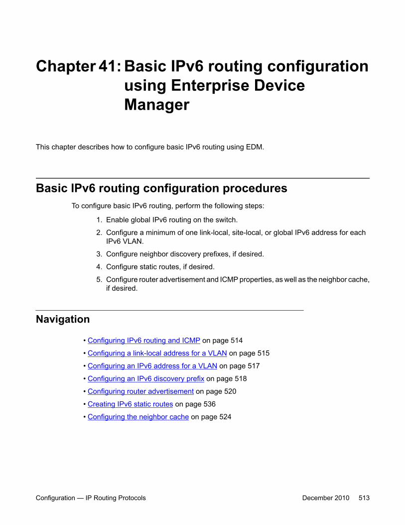
Chapter 41: Basic IPv6 routing configurationusing Enterprise DeviceManager
This chapter describes how to configure basic IPv6 routing using EDM.
Basic IPv6 routing configuration proceduresTo configure basic IPv6 routing, perform the following steps:
1. Enable global IPv6 routing on the switch.
2. Configure a minimum of one link-local, site-local, or global IPv6 address for eachIPv6 VLAN.
3. Configure neighbor discovery prefixes, if desired.
4. Configure static routes, if desired.
5. Configure router advertisement and ICMP properties, as well as the neighbor cache,if desired.
Navigation
• Configuring IPv6 routing and ICMP on page 514
• Configuring a link-local address for a VLAN on page 515
• Configuring an IPv6 address for a VLAN on page 517
• Configuring an IPv6 discovery prefix on page 518
• Configuring router advertisement on page 520
• Creating IPv6 static routes on page 536
• Configuring the neighbor cache on page 524
Configuration — IP Routing Protocols December 2010 513

Configuring IPv6 routing and ICMPEnable IPv6 routing to route IPv6 traffic on the switch. IPv6 packets transport Internet ControlMessage Protocol (ICMP) error and information messages. Configure the rate, in milliseconds,at which ICMP sends messages to conserve system resources.
Procedure steps
1. From the navigation tree, double-click IPv6.
2. Double-click IPv6.
3. To enable IPv6 routing, in the Forwarding box, select forwarding.
4. Configure the routing and ICMP parameters as required.
5. Click Apply.
Variable definitionsThe following table describes the fields of the IPv6 Globals tab.
Variable ValueAdminEnabled Configures IPv6 as administratively enabled
or disabled.
OperEnabled Indicates whether IPv6 is operationallyenabled or disabled.
Forwarding Configures whether this entity is an IPv6router with respect to the forwarding ofdatagrams received by, but not addressed to,this entity. Select forwarding to act as arouter. Select notForwarding to not act as arouter. The default is notForwarding.
DefaultHopLimit Configures the hop limit. The default is 30.
IcmpNetUnreach If selected, enables the ICMP networkunreachable feature. The default is disabled.
IcmpRedirectMsg If selected, enables the ICMP redirectmessage feature. The default is disabled.
IcmpErrorInterval Configures the interval (in milliseconds) forsending ICMPv6 error messages. The
Basic IPv6 routing configuration using Enterprise Device Manager
514 Configuration — IP Routing Protocols December 2010
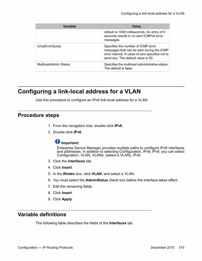
Variable Valuedefault is 1000 milliseconds. An entry of 0seconds results in no sent ICMPv6 errormessages.
IcmpErrorQuota Specifies the number of ICMP errormessages that can be sent during the ICMPerror interval. A value of zero specifies not tosend any. The default value is 50.
MulticastAdmin Status Specifies the multicast administrative status.The default is false.
Configuring a link-local address for a VLANUse this procedure to configure an IPv6 link-local address for a VLAN.
Procedure steps
1. From the navigation tree, double-click IPv6.
2. Double-click IPv6.
Important:Enterprise Device Manager provides multiple paths to configure IPv6 interfacesand addresses. In addition to selecting Configuration, IPv6, IPv6, you can selectConfiguration, VLAN, VLANs, (select a VLAN), IPv6.
3. Click the Interfaces tab.
4. Click Insert.
5. In the IfIndex box, click VLAN, and select a VLAN.
6. You must select the AdminStatus check box before the interface takes effect.
7. Edit the remaining fields.
8. Click Insert.
9. Click Apply.
Variable definitionsThe following table describes the fields of the Interfaces tab.
Configuring a link-local address for a VLAN
Configuration — IP Routing Protocols December 2010 515
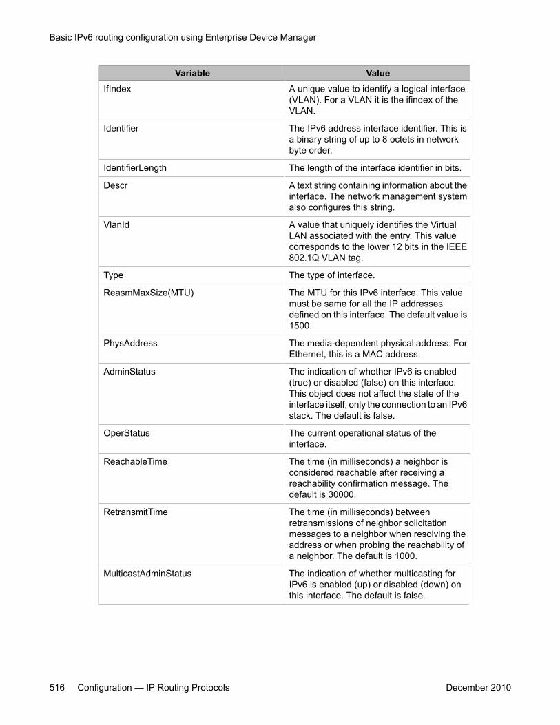
Variable ValueIfIndex A unique value to identify a logical interface
(VLAN). For a VLAN it is the ifindex of theVLAN.
Identifier The IPv6 address interface identifier. This isa binary string of up to 8 octets in networkbyte order.
IdentifierLength The length of the interface identifier in bits.
Descr A text string containing information about theinterface. The network management systemalso configures this string.
VlanId A value that uniquely identifies the VirtualLAN associated with the entry. This valuecorresponds to the lower 12 bits in the IEEE802.1Q VLAN tag.
Type The type of interface.
ReasmMaxSize(MTU) The MTU for this IPv6 interface. This valuemust be same for all the IP addressesdefined on this interface. The default value is1500.
PhysAddress The media-dependent physical address. ForEthernet, this is a MAC address.
AdminStatus The indication of whether IPv6 is enabled(true) or disabled (false) on this interface.This object does not affect the state of theinterface itself, only the connection to an IPv6stack. The default is false.
OperStatus The current operational status of theinterface.
ReachableTime The time (in milliseconds) a neighbor isconsidered reachable after receiving areachability confirmation message. Thedefault is 30000.
RetransmitTime The time (in milliseconds) betweenretransmissions of neighbor solicitationmessages to a neighbor when resolving theaddress or when probing the reachability ofa neighbor. The default is 1000.
MulticastAdminStatus The indication of whether multicasting forIPv6 is enabled (up) or disabled (down) onthis interface. The default is false.
Basic IPv6 routing configuration using Enterprise Device Manager
516 Configuration — IP Routing Protocols December 2010
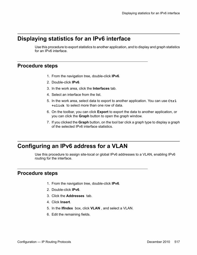
Displaying statistics for an IPv6 interfaceUse this procedure to export statistics to another application, and to display and graph statisticsfor an IPv6 interface.
Procedure steps
1. From the navigation tree, double-click IPv6.
2. Double-click IPv6.
3. In the work area, click the Interfaces tab.
4. Select an interface from the list.
5. In the work area, select data to export to another application. You can use Ctrl+click to select more than one row of data.
6. On the toolbar, you can click Export to export the data to another application, oryou can click the Graph button to open the graph window.
7. If you clicked the Graph button, on the tool bar click a graph type to display a graphof the selected IPv6 interface statistics.
Configuring an IPv6 address for a VLANUse this procedure to assign site-local or global IPv6 addresses to a VLAN, enabling IPv6routing for the interface.
Procedure steps
1. From the navigation tree, double-click IPv6.
2. Double-click IPv6.
3. Click the Addresses tab.
4. Click Insert.
5. In the IfIndex box, click VLAN , and select a VLAN.
6. Edit the remaining fields.
Displaying statistics for an IPv6 interface
Configuration — IP Routing Protocols December 2010 517
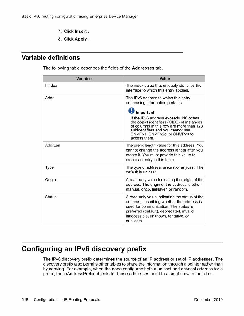
7. Click Insert .
8. Click Apply .
Variable definitionsThe following table describes the fields of the Addresses tab.
Variable ValueIfIndex The index value that uniquely identifies the
interface to which this entry applies.
Addr The IPv6 address to which this entryaddressing information pertains.
Important:If the IPv6 address exceeds 116 octets,the object identifiers (OIDS) of instancesof columns in this row are more than 128subidentifiers and you cannot useSNMPv1, SNMPv2c, or SNMPv3 toaccess them.
AddrLen The prefix length value for this address. Youcannot change the address length after youcreate it. You must provide this value tocreate an entry in this table.
Type The type of address: unicast or anycast. Thedefault is unicast.
Origin A read-only value indicating the origin of theaddress. The origin of the address is other,manual, dhcp, linklayer, or random.
Status A read-only value indicating the status of theaddress, describing whether the address isused for communication. The status ispreferred (default), deprecated, invalid,inaccessible, unknown, tentative, orduplicate.
Configuring an IPv6 discovery prefixThe IPv6 discovery prefix determines the source of an IP address or set of IP addresses. Thediscovery prefix also permits other tables to share the information through a pointer rather thanby copying. For example, when the node configures both a unicast and anycast address for aprefix, the ipAddressPrefix objects for those addresses point to a single row in the table.
Basic IPv6 routing configuration using Enterprise Device Manager
518 Configuration — IP Routing Protocols December 2010
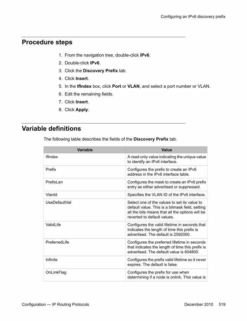
Procedure steps
1. From the navigation tree, double-click IPv6.
2. Double-click IPv6.
3. Click the Discovery Prefix tab.
4. Click Insert.
5. In the IfIndex box, click Port or VLAN, and select a port number or VLAN.
6. Edit the remaining fields.
7. Click Insert.
8. Click Apply.
Variable definitionsThe following table describes the fields of the Discovery Prefix tab.
Variable ValueIfIndex A read-only value indicating the unique value
to identify an IPv6 interface.
Prefix Configures the prefix to create an IPv6address in the IPv6 interface table.
PrefixLen Configures the mask to create an IPv6 prefixentry as either advertised or suppressed.
VlanId Specifies the VLAN ID of the IPv6 interface.
UseDefaultVal Select one of the values to set its value todefault value. This is a bitmask field, settingall the bits means that all the options will bereverted to default values.
ValidLife Configures the valid lifetime in seconds thatindicates the length of time this prefix isadvertised. The default is 2592000.
PreferredLife Configures the preferred lifetime in secondsthat indicates the length of time this prefix isadvertised. The default value is 604800.
Infinite Configures the prefix valid lifetime so it neverexpires. The default is false.
OnLinkFlag Configures the prefix for use whendetermining if a node is onlink. This value is
Configuring an IPv6 discovery prefix
Configuration — IP Routing Protocols December 2010 519
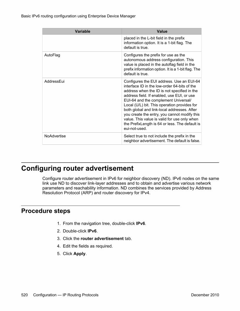
Variable Valueplaced in the L-bit field in the prefixinformation option. It is a 1-bit flag. Thedefault is true.
AutoFlag Configures the prefix for use as theautonomous address configuration. Thisvalue is placed in the autoflag field in theprefix information option. It is a 1-bit flag. Thedefault is true.
AddressEui Configures the EUI address. Use an EUI-64interface ID in the low-order 64-bits of theaddress when the ID is not specified in theaddress field. If enabled, use EUI, or useEUI-64 and the complement Universal/Local (U/L) bit. This operation provides forboth global and link-local addresses. Afteryou create the entry, you cannot modify thisvalue. This value is valid for use only whenthe PrefixLength is 64 or less. The default iseui-not-used.
NoAdvertise Select true to not include the prefix in theneighbor advertisement. The default is false.
Configuring router advertisementConfigure router advertisement in IPv6 for neighbor discovery (ND). IPv6 nodes on the samelink use ND to discover link-layer addresses and to obtain and advertise various networkparameters and reachability information. ND combines the services provided by AddressResolution Protocol (ARP) and router discovery for IPv4.
Procedure steps
1. From the navigation tree, double-click IPv6.
2. Double-click IPv6.
3. Click the router advertisement tab.
4. Edit the fields as required.
5. Click Apply.
Basic IPv6 routing configuration using Enterprise Device Manager
520 Configuration — IP Routing Protocols December 2010
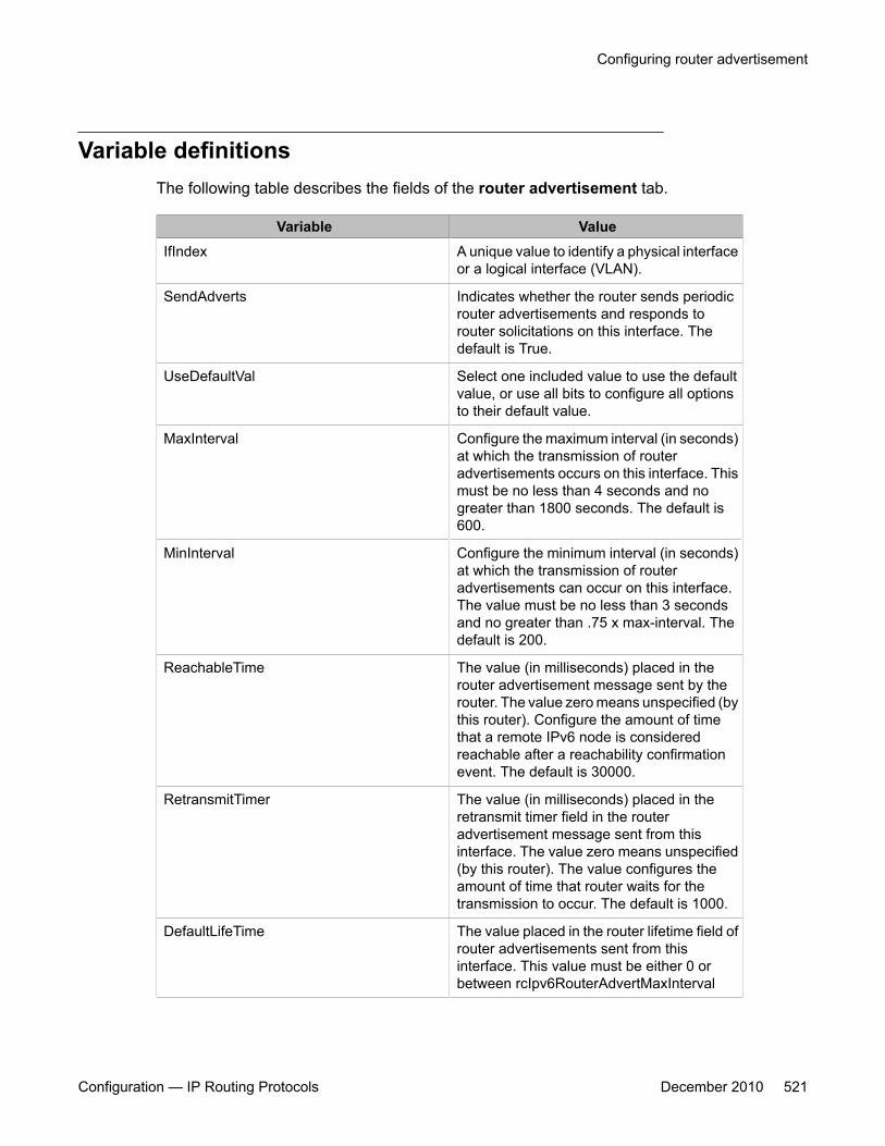
Variable definitionsThe following table describes the fields of the router advertisement tab.
Variable ValueIfIndex A unique value to identify a physical interface
or a logical interface (VLAN).
SendAdverts Indicates whether the router sends periodicrouter advertisements and responds torouter solicitations on this interface. Thedefault is True.
UseDefaultVal Select one included value to use the defaultvalue, or use all bits to configure all optionsto their default value.
MaxInterval Configure the maximum interval (in seconds)at which the transmission of routeradvertisements occurs on this interface. Thismust be no less than 4 seconds and nogreater than 1800 seconds. The default is600.
MinInterval Configure the minimum interval (in seconds)at which the transmission of routeradvertisements can occur on this interface.The value must be no less than 3 secondsand no greater than .75 x max-interval. Thedefault is 200.
ReachableTime The value (in milliseconds) placed in therouter advertisement message sent by therouter. The value zero means unspecified (bythis router). Configure the amount of timethat a remote IPv6 node is consideredreachable after a reachability confirmationevent. The default is 30000.
RetransmitTimer The value (in milliseconds) placed in theretransmit timer field in the routeradvertisement message sent from thisinterface. The value zero means unspecified(by this router). The value configures theamount of time that router waits for thetransmission to occur. The default is 1000.
DefaultLifeTime The value placed in the router lifetime field ofrouter advertisements sent from thisinterface. This value must be either 0 orbetween rcIpv6RouterAdvertMaxInterval
Configuring router advertisement
Configuration — IP Routing Protocols December 2010 521

Variable Valueand 9000 seconds. A value of zero indicatesthat the router is not a default router. Thedefault is 3 times the value ofrcIpv6RouterAdvertMaxInterval or 1800.
CurHopLimit The default value placed in the current hoplimit field in router advertisements sent fromthis interface. The value must be the currentdiameter of the Internet. A value of zero inthe router advertisement indicates that theadvertisement is not specifying a value forurHopLimit. The value must be the valuespecified in the IANA Web pages(www.iana.org). The default is 30.
ManagedFlag If enabled, the ManagedFlag configures theM-bit or the managed address configurationin the router advertisement. The default isfalse.
OtherConfigFlag If set to true, then the O-bit (Other statefulconfiguration) in the router advertisement isset. Reference RFC2461 Section 6.2.1. Thedefault value is false.
DadNSNum The number of neighbor solicitationmessages for duplicate address detection(DAD). A value of 0 disables the DADprocess on this interface. A value of 1 sendsone advertisement without retransmissions.
LinkMTU The value placed in MTU options sent by therouter on this interface. A value of zeroindicates that the router sends no MTUoptions.
Creating IPv6 static routesUse this procedure to configure static routes to destination IPv6 address prefixes.
Procedure steps
1. From the navigation tree, double-click IPv6.
2. Double-click IPv6.
Basic IPv6 routing configuration using Enterprise Device Manager
522 Configuration — IP Routing Protocols December 2010
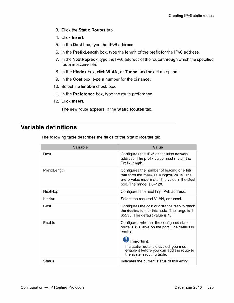
3. Click the Static Routes tab.
4. Click Insert.
5. In the Dest box, type the IPv6 address.
6. In the PrefixLength box, type the length of the prefix for the IPv6 address.
7. In the NextHop box, type the IPv6 address of the router through which the specifiedroute is accessible.
8. In the IfIndex box, click VLAN, or Tunnel and select an option.
9. In the Cost box, type a number for the distance.
10. Select the Enable check box.
11. In the Preference box, type the route preference.
12. Click Insert.
The new route appears in the Static Routes tab.
Variable definitionsThe following table describes the fields of the Static Routes tab.
Variable ValueDest Configures the IPv6 destination network
address. The prefix value must match thePrefixLength.
PrefixLength Configures the number of leading one bitsthat form the mask as a logical value. Theprefix value must match the value in the Destbox. The range is 0–128.
NextHop Configures the next hop IPv6 address.
IfIndex Select the required VLAN, or tunnel.
Cost Configures the cost or distance ratio to reachthe destination for this node. The range is 1–65535. The default value is 1.
Enable Configures whether the configured staticroute is available on the port. The default isenable.
Important:If a static route is disabled, you mustenable it before you can add the route tothe system routing table.
Status Indicates the current status of this entry.
Creating IPv6 static routes
Configuration — IP Routing Protocols December 2010 523
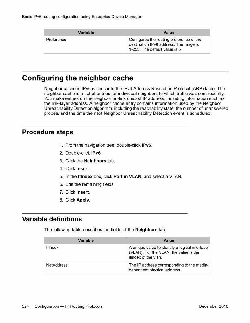
Variable ValuePreference Configures the routing preference of the
destination IPv6 address. The range is1-255. The default value is 5.
Configuring the neighbor cacheNeighbor cache in IPv6 is similar to the IPv4 Address Resolution Protocol (ARP) table. Theneighbor cache is a set of entries for individual neighbors to which traffic was sent recently.You make entries on the neighbor on-link unicast IP address, including information such asthe link-layer address. A neighbor cache entry contains information used by the NeighborUnreachability Detection algorithm, including the reachability state, the number of unansweredprobes, and the time the next Neighbor Unreachability Detection event is scheduled.
Procedure steps
1. From the navigation tree, double-click IPv6.
2. Double-click IPv6.
3. Click the Neighbors tab.
4. Click Insert.
5. In the IfIndex box, click Port in VLAN, and select a VLAN.
6. Edit the remaining fields.
7. Click Insert.
8. Click Apply.
Variable definitionsThe following table describes the fields of the Neighbors tab.
Variable ValueIfIndex A unique value to identify a logical interface
(VLAN). For the VLAN, the value is theifindex of the vlan.
NetAddress The IP address corresponding to the media-dependent physical address.
Basic IPv6 routing configuration using Enterprise Device Manager
524 Configuration — IP Routing Protocols December 2010
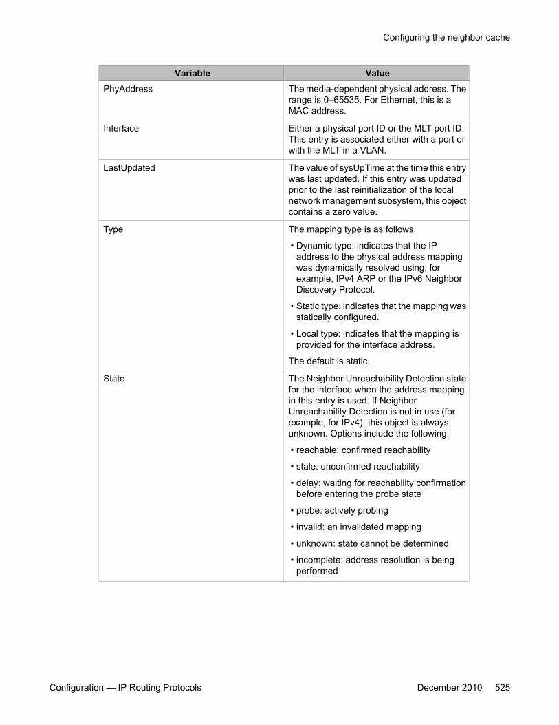
Variable ValuePhyAddress The media-dependent physical address. The
range is 0–65535. For Ethernet, this is aMAC address.
Interface Either a physical port ID or the MLT port ID.This entry is associated either with a port orwith the MLT in a VLAN.
LastUpdated The value of sysUpTime at the time this entrywas last updated. If this entry was updatedprior to the last reinitialization of the localnetwork management subsystem, this objectcontains a zero value.
Type The mapping type is as follows:
• Dynamic type: indicates that the IPaddress to the physical address mappingwas dynamically resolved using, forexample, IPv4 ARP or the IPv6 NeighborDiscovery Protocol.
• Static type: indicates that the mapping wasstatically configured.
• Local type: indicates that the mapping isprovided for the interface address.
The default is static.
State The Neighbor Unreachability Detection statefor the interface when the address mappingin this entry is used. If NeighborUnreachability Detection is not in use (forexample, for IPv4), this object is alwaysunknown. Options include the following:
• reachable: confirmed reachability
• stale: unconfirmed reachability
• delay: waiting for reachability confirmationbefore entering the probe state
• probe: actively probing
• invalid: an invalidated mapping
• unknown: state cannot be determined
• incomplete: address resolution is beingperformed
Configuring the neighbor cache
Configuration — IP Routing Protocols December 2010 525

Basic IPv6 routing configuration using Enterprise Device Manager
526 Configuration — IP Routing Protocols December 2010
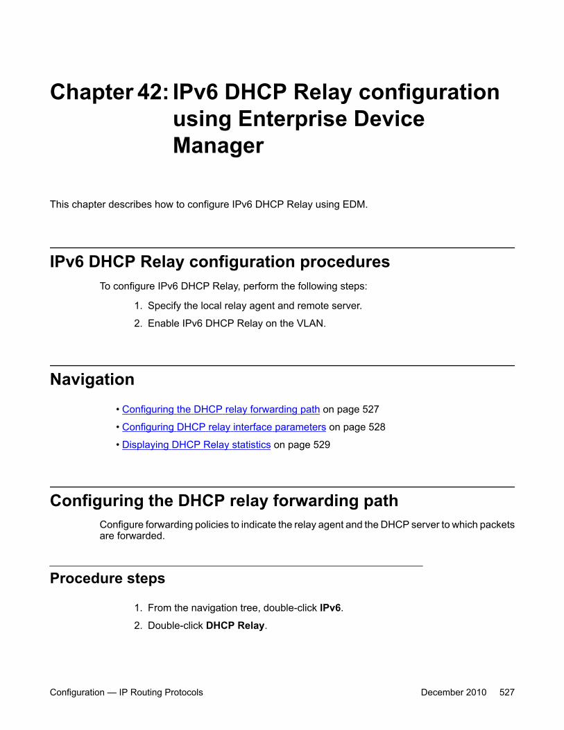
Chapter 42: IPv6 DHCP Relay configurationusing Enterprise DeviceManager
This chapter describes how to configure IPv6 DHCP Relay using EDM.
IPv6 DHCP Relay configuration proceduresTo configure IPv6 DHCP Relay, perform the following steps:
1. Specify the local relay agent and remote server.
2. Enable IPv6 DHCP Relay on the VLAN.
Navigation• Configuring the DHCP relay forwarding path on page 527
• Configuring DHCP relay interface parameters on page 528
• Displaying DHCP Relay statistics on page 529
Configuring the DHCP relay forwarding pathConfigure forwarding policies to indicate the relay agent and the DHCP server to which packetsare forwarded.
Procedure steps
1. From the navigation tree, double-click IPv6.
2. Double-click DHCP Relay.
Configuration — IP Routing Protocols December 2010 527
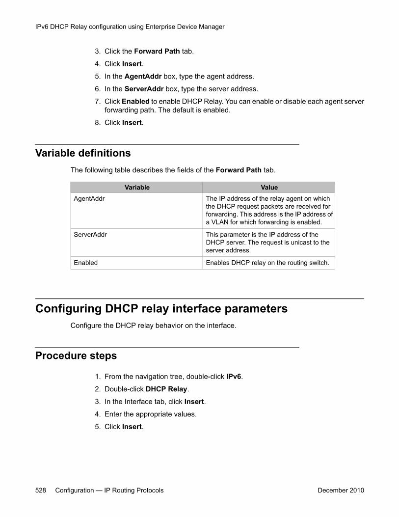
3. Click the Forward Path tab.
4. Click Insert.
5. In the AgentAddr box, type the agent address.
6. In the ServerAddr box, type the server address.
7. Click Enabled to enable DHCP Relay. You can enable or disable each agent serverforwarding path. The default is enabled.
8. Click Insert.
Variable definitionsThe following table describes the fields of the Forward Path tab.
Variable ValueAgentAddr The IP address of the relay agent on which
the DHCP request packets are received forforwarding. This address is the IP address ofa VLAN for which forwarding is enabled.
ServerAddr This parameter is the IP address of theDHCP server. The request is unicast to theserver address.
Enabled Enables DHCP relay on the routing switch.
Configuring DHCP relay interface parametersConfigure the DHCP relay behavior on the interface.
Procedure steps
1. From the navigation tree, double-click IPv6.
2. Double-click DHCP Relay.
3. In the Interface tab, click Insert.
4. Enter the appropriate values.
5. Click Insert.
IPv6 DHCP Relay configuration using Enterprise Device Manager
528 Configuration — IP Routing Protocols December 2010

Variable definitionsThe following table describes the fields of the Interface tab.
Variable ValueIfIndex A read-only value indicating the unique value
to identify an IPv6 interface.
MaxHop Specifies the maximum number of hops aDHCP packet can take from the DHCP clientto the DHCP server.
RemoteIdEnabled Enables or disables remote ID.
Displaying DHCP Relay statisticsDisplay DHCP Relay statistics to monitor network performance.
Procedure steps
1. From the navigation tree, double-click IPv6.
2. Double-click DHCP Relay.
3. In the Interface tab, select an interface and click the Stats.
Variable definitionsThe following table describes the fields of the Stats tab.
Variable ValueNumRequests The count of request messages.
NumReplies The count of reply messages.
Displaying DHCP Relay statistics
Configuration — IP Routing Protocols December 2010 529

IPv6 DHCP Relay configuration using Enterprise Device Manager
530 Configuration — IP Routing Protocols December 2010

Chapter 43: IPv6 Tunnel configuration usingEnterprise Device Manager
This chapter describes how to configure IPv6 tunnels using EDM.
IPv6 tunnel configuration proceduresTo configure IPv6 tunnels, perform the following steps:
1. Configure the tunnel at the source and destination switch.
2. Configure static routes at the source and destination switch.
3. Optionally, configure the tunnel hop limit.
Navigation• Configuring a tunnel for IPv6 VLANs to communicate through an IPv4 network on
page 531
• Viewing the local IPv6 address associated with a tunnel on page 533
• Modifying tunnel hop limits on page 534
• Creating IPv6 static routes on page 536
Configuring a tunnel for IPv6 VLANs to communicatethrough an IPv4 network
Use the following procedure to configure a tunnel for IPv6 VLANs to communicate through anIPv4 network. Manual tunnels are point-to-point, so you configure both source and destinationaddresses. You must configure both IPv6 and IPv4 addresses for both source and destinationdevices. The IPv6 addresses must represent the same network, for example 6666::1/96 and6666::2/96.
Configuration — IP Routing Protocols December 2010 531
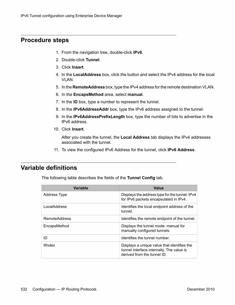
Procedure steps
1. From the navigation tree, double-click IPv6.
2. Double-click Tunnel.
3. Click Insert.
4. In the LocalAddress box, click the button and select the IPv4 address for the localVLAN.
5. In the RemoteAddress box, type the IPv4 address for the remote destination VLAN.
6. In the EncapsMethod area, select manual.
7. In the ID box, type a number to represent the tunnel.
8. In the IPv6AddressAddr box, type the IPv6 address assigned to the tunnel.
9. In the IPv6AddressPrefixLength box, type the number of bits to advertise in theIPv6 address.
10. Click Insert.
After you create the tunnel, the Local Address tab displays the IPv4 addressesassociated with the tunnel.
11. To view the configured IPv6 Address for the tunnel, click IPv6 Address.
Variable definitionsThe following table describes the fields of the Tunnel Config tab.
Variable ValueAddress Type Displays the address type for the tunnel: IPv4
for IPv6 packets encapsulated in IPv4.
LocalAddress Identifies the local endpoint address of thetunnel.
RemoteAddress Identifies the remote endpoint of the tunnel.
EncapsMethod Displays the tunnel mode: manual formanually configured tunnels.
ID Identifies the tunnel number.
IfIndex Displays a unique value that identifies thetunnel interface internally. The value isderived from the tunnel ID.
IPv6 Tunnel configuration using Enterprise Device Manager
532 Configuration — IP Routing Protocols December 2010
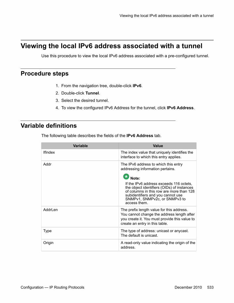
Viewing the local IPv6 address associated with a tunnelUse this procedure to view the local IPv6 address associated with a pre-configured tunnel.
Procedure steps
1. From the navigation tree, double-click IPv6.
2. Double-click Tunnel.
3. Select the desired tunnel.
4. To view the configured IPv6 Address for the tunnel, click IPv6 Address.
Variable definitionsThe following table describes the fields of the IPv6 Address tab.
Variable ValueIfIndex The index value that uniquely identifies the
interface to which this entry applies.
Addr The IPv6 address to which this entryaddressing information pertains.
Note:If the IPv6 address exceeds 116 octets,the object identifiers (OIDs) of instancesof columns in this row are more than 128subidentifiers and you cannot useSNMPv1, SNMPv2c, or SNMPv3 toaccess them.
AddrLen The prefix length value for this address.You cannot change the address length afteryou create it. You must provide this value tocreate an entry in this table.
Type The type of address: unicast or anycast.The default is unicast.
Origin A read-only value indicating the origin of theaddress.
Viewing the local IPv6 address associated with a tunnel
Configuration — IP Routing Protocols December 2010 533
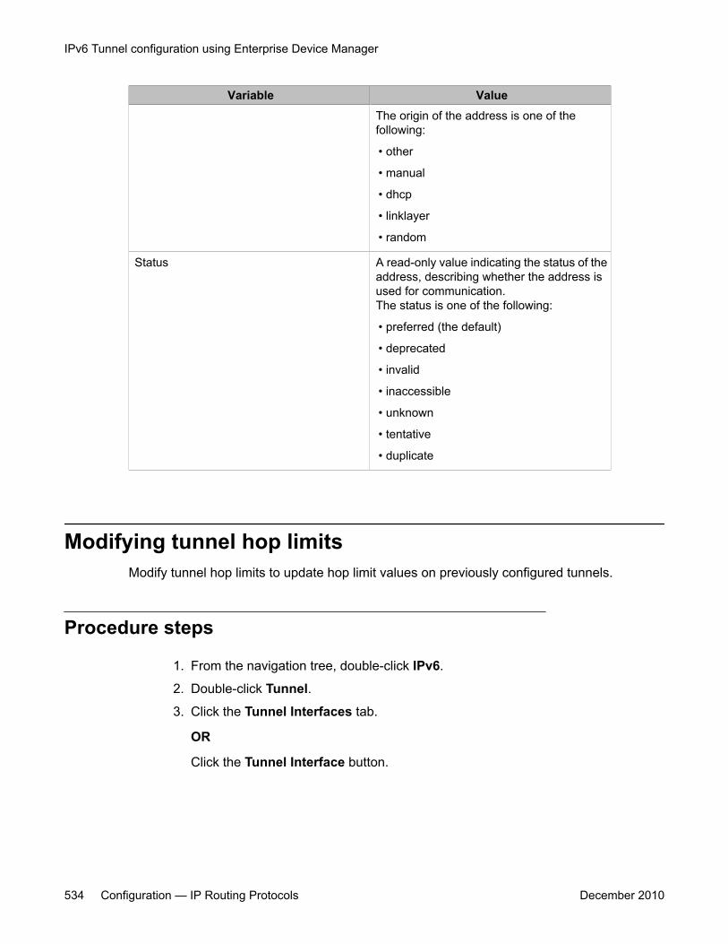
Variable ValueThe origin of the address is one of thefollowing:
• other
• manual
• dhcp
• linklayer
• random
Status A read-only value indicating the status of theaddress, describing whether the address isused for communication.The status is one of the following:
• preferred (the default)
• deprecated
• invalid
• inaccessible
• unknown
• tentative
• duplicate
Modifying tunnel hop limitsModify tunnel hop limits to update hop limit values on previously configured tunnels.
Procedure steps
1. From the navigation tree, double-click IPv6.
2. Double-click Tunnel.
3. Click the Tunnel Interfaces tab.
OR
Click the Tunnel Interface button.
IPv6 Tunnel configuration using Enterprise Device Manager
534 Configuration — IP Routing Protocols December 2010
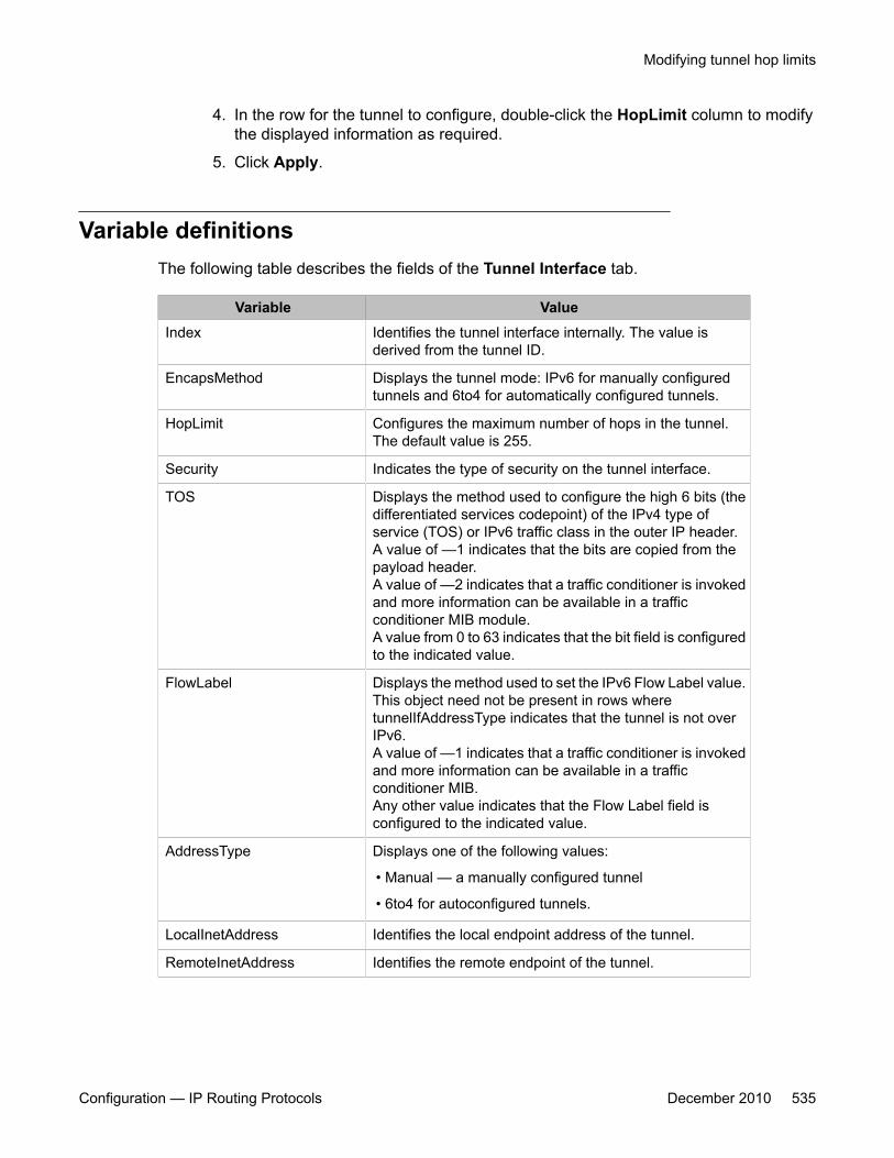
4. In the row for the tunnel to configure, double-click the HopLimit column to modifythe displayed information as required.
5. Click Apply.
Variable definitionsThe following table describes the fields of the Tunnel Interface tab.
Variable ValueIndex Identifies the tunnel interface internally. The value is
derived from the tunnel ID.
EncapsMethod Displays the tunnel mode: IPv6 for manually configuredtunnels and 6to4 for automatically configured tunnels.
HopLimit Configures the maximum number of hops in the tunnel.The default value is 255.
Security Indicates the type of security on the tunnel interface.
TOS Displays the method used to configure the high 6 bits (thedifferentiated services codepoint) of the IPv4 type ofservice (TOS) or IPv6 traffic class in the outer IP header.A value of —1 indicates that the bits are copied from thepayload header.A value of —2 indicates that a traffic conditioner is invokedand more information can be available in a trafficconditioner MIB module.A value from 0 to 63 indicates that the bit field is configuredto the indicated value.
FlowLabel Displays the method used to set the IPv6 Flow Label value.This object need not be present in rows wheretunnelIfAddressType indicates that the tunnel is not overIPv6.A value of —1 indicates that a traffic conditioner is invokedand more information can be available in a trafficconditioner MIB.Any other value indicates that the Flow Label field isconfigured to the indicated value.
AddressType Displays one of the following values:
• Manual — a manually configured tunnel
• 6to4 for autoconfigured tunnels.
LocalInetAddress Identifies the local endpoint address of the tunnel.
RemoteInetAddress Identifies the remote endpoint of the tunnel.
Modifying tunnel hop limits
Configuration — IP Routing Protocols December 2010 535
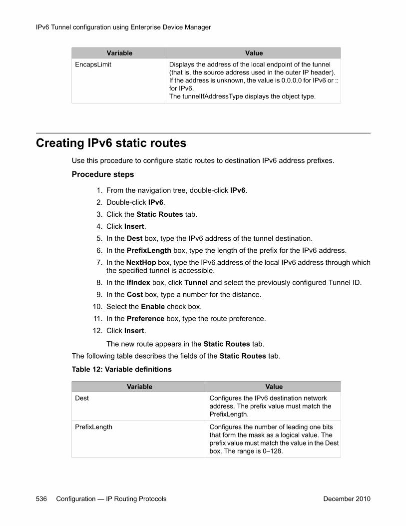
Variable ValueEncapsLimit Displays the address of the local endpoint of the tunnel
(that is, the source address used in the outer IP header).If the address is unknown, the value is 0.0.0.0 for IPv6 or ::for IPv6.The tunnelIfAddressType displays the object type.
Creating IPv6 static routesUse this procedure to configure static routes to destination IPv6 address prefixes.
Procedure steps
1. From the navigation tree, double-click IPv6.2. Double-click IPv6.3. Click the Static Routes tab.4. Click Insert.5. In the Dest box, type the IPv6 address of the tunnel destination.6. In the PrefixLength box, type the length of the prefix for the IPv6 address.7. In the NextHop box, type the IPv6 address of the local IPv6 address through which
the specified tunnel is accessible.8. In the IfIndex box, click Tunnel and select the previously configured Tunnel ID.9. In the Cost box, type a number for the distance.
10. Select the Enable check box.11. In the Preference box, type the route preference.12. Click Insert.
The new route appears in the Static Routes tab.The following table describes the fields of the Static Routes tab.
Table 12: Variable definitions
Variable ValueDest Configures the IPv6 destination network
address. The prefix value must match thePrefixLength.
PrefixLength Configures the number of leading one bitsthat form the mask as a logical value. Theprefix value must match the value in the Destbox. The range is 0–128.
IPv6 Tunnel configuration using Enterprise Device Manager
536 Configuration — IP Routing Protocols December 2010
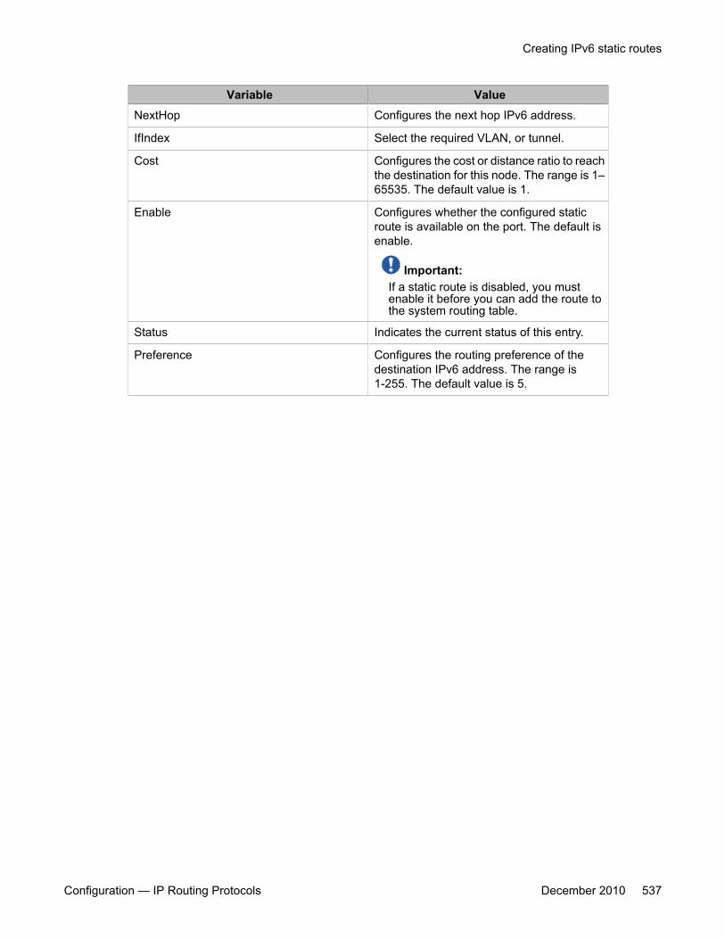
Variable ValueNextHop Configures the next hop IPv6 address.
IfIndex Select the required VLAN, or tunnel.
Cost Configures the cost or distance ratio to reachthe destination for this node. The range is 1–65535. The default value is 1.
Enable Configures whether the configured staticroute is available on the port. The default isenable.
Important:If a static route is disabled, you mustenable it before you can add the route tothe system routing table.
Status Indicates the current status of this entry.
Preference Configures the routing preference of thedestination IPv6 address. The range is1-255. The default value is 5.
Creating IPv6 static routes
Configuration — IP Routing Protocols December 2010 537

IPv6 Tunnel configuration using Enterprise Device Manager
538 Configuration — IP Routing Protocols December 2010