aviation fuel contaminant test kit nsn 6630-01-008-5524 · nsn 6630-01-008-5524 distribution...
TRANSCRIPT
T M 5 - 6 6 3 0 - 2 1 8 - 1 0
T E C H N I C A L M A N U A L
O P E R A T O R ’ S M A N U A L
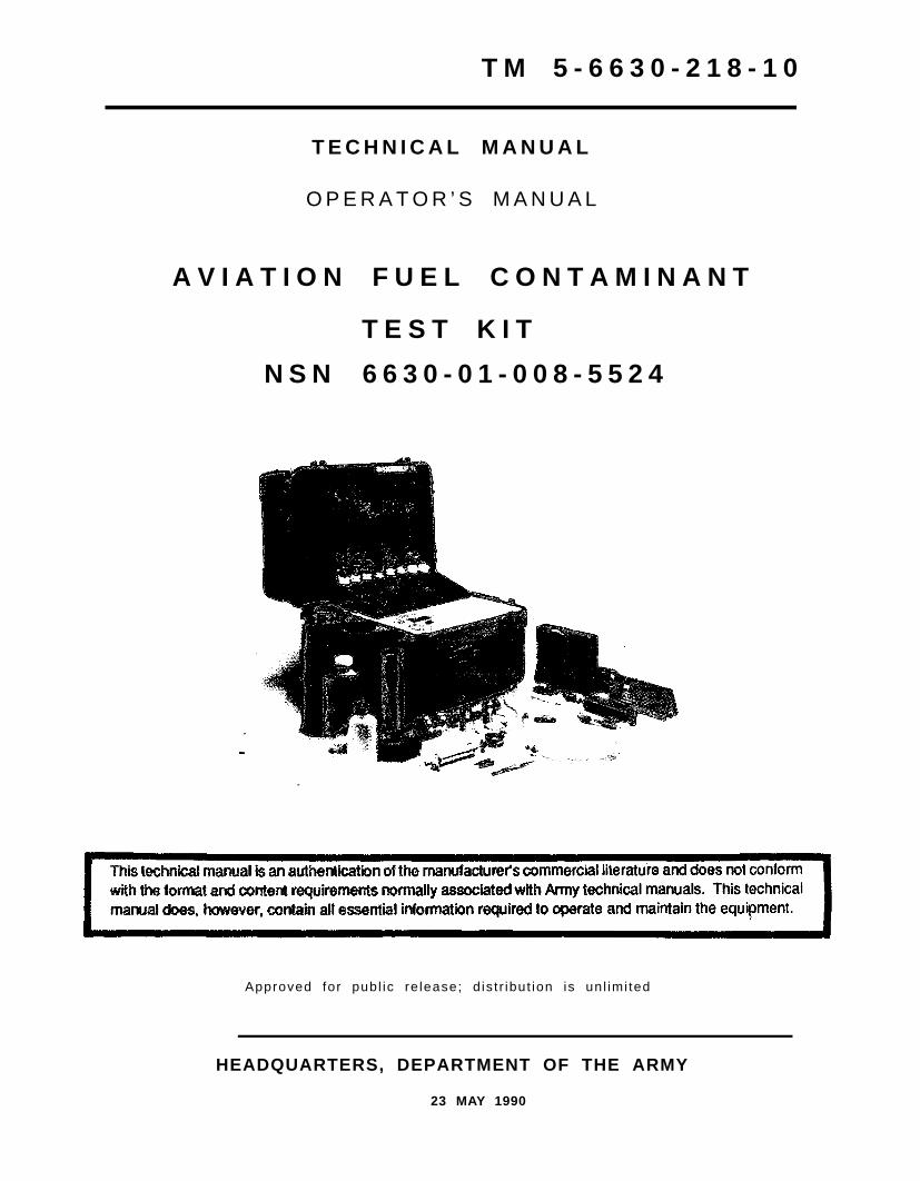
A V I A T I O N F U E L C O N T A M I N A N T
T E S T K I T
N S N 6 6 3 0 - 0 1 - 0 0 8 - 5 5 2 4
Approved for publ ic re lease; d is t r ibut ion is un l imi ted
HEADQUARTERS, DEPARTMENT OF THE ARMY
23 MAY 1990

Milton H. Hamilton
TM 5-6630-218-10C1
C H A N G E
NO. 1
HEADQUARTERSDEPARTMENT OF THE ARMY
WASHINGTON, D.C., 31 October 1994
OPERATOR’S MANUAL
Remove pages
AVIATION FUEL CONTAMINANTTEST KIT
NSN 6630-01-008-5524
DISTRIBUTION STATEMENT A: Approved for public release; distribution is unlimited
TM 5-6630-218-10, 23 May 1990, is changed as follows:
1. Remove and insert pages as indicated below. New or changed text material is indicated by a vertical barin the margin. An illustration change is indicated by a miniature pointing hand.
Insert pages
Intro page1-5 and 1-6
Intro page1-5 and 1-6
By Order of the Secretary of the Army:
MILTON H. HAMILTONAdministrative Assistant to the
Secretary of the Army07519
GORDON R. SULLIVANGeneral, United States Army
Chief of Staff
DISTRIBUTION:To be distributed in accordance with DA Form 12-25-E, block no. 5440, requirements for
TM 5-6630-218-10.

REPORTING ERRORS AND RECOMMENDING IMPROVEMENTS
You can help improve this manual. If you find any mistake or if you know of a way to improve the procedures,please let us know. Mail your Ietter, DA Form 2028 (Recommended Changes to Publications and BlankForms), or DA Form 2028-2 located in the back of this manual direct to: Commander, U.S. Army Aviation andTroop Command, ATTN: AMSAT-I-MP, 4300 Goodfellow Blvd., St. Louis, MO 63120-1798. A reply will befurnished directly to you.
Approved for public release; distribution is unlimited
Current as of 21 March 1990.
This technical manual is an authentication of the manufacturer’s commercial litera-ture and does not conform with the format and content requirements normallyassociated with Army technical manuals. This technical manual does, however, con-tain all essential information required to operate and maintain the equipment.
Change 1

TM 5-6630-218-10
Table of Contents
Section Page
Chapter 1.0 General Information . . . . . . . . . . . . . . . . . 1-1
1.1
1.2
1.3
1.4
1.5
1.6
1.7
Description. . . . . . . . . . . . . . . . . . . . . . . . . . . . . . . . . . . . 1-1
Scope. . . . . . . . . . . . . . . . .. . . . . . . . . . . . . . . . . . . . . . . . . . ..1-1
Documentation . . . . . . . . . . . . . . . . . . . . . . . . . . . . . . . . . . . . ..1-1
Equipment Specifications . . . . . . . . . . . . . . . . . . . . . . . . ..1-1
Kit Components (equipment and expendables) . . . . . . . . . . . . ..1-2
Operating Climatic Conditions . . . . . . .. . . . . . . . . . . . . . . . ..1-6
Storage Climatic Conditions . . . . . . . .. . . . . . . . ..1-6
1.8 Transportability . . . . . . . . . . . . . . . . . . . . . . . ..1-6
Chapter 2.0 Operating Instructions . . . . . . . . . . . . . . . . . . . . . . 2-1
2.12.1.1
2.2
2.32.3.12.3.1.12.3.22.3.3
2.3.42.3.5
2.3.6
2.3.72.3.82.3.92.3.10
Introduction . . . . . . . . . . . . . . . . . . . . . . . . . . . . . . . . . . . . . ..2-1Applicable Documents. . . . . . . . . . .. . . . . . . . . . . . . . . . . . . . . . . .2-1
Aviation Fuel Sample . . . . . . . . . . . . . . . . . . . . . . . . . . . . . . . . . . . . . 2-1
Operating Instructions for Particulate Contaminants Test . . . . . . .2-2Required Equipment and Expendables . . . . . . . . . . . . . . . . . . . ...2-2Methods for Particulate Contaminants Testing. . . . . . . . . . . . . . . . 2-3
Installing the Quick-Release Valve. . . . . . . . . . . . . . . . . . . . 2-3Inserting the Monitor into Sampler Valve Hose . . . . .. . . . . 2-4AssemblyAssembling the Sampler Valve Hose Assembly . . . . . . ...2-6Attaching the Remote Sampling Assembly to the . . . .. . . ...2-6Sampler Valve Hose AssemblyConnecting the Sampler Valve Hose Assembly . . . . . . . . . . .2-7to the Quick-Release ValveFlushing the Inlet Hose . . . . . . . . . . . . . . . . . . . ..2-10Taking a Sample . . . . . . . . . . . . . . . . . . . . . . . . . . . 2-11Pumping the Monitor Dry . . . . . . . . . . . . . . . . . . . . . . . . 2-13Preparing the Monitor for Assessment of Particulate . . . . . . ..2-14Contamination
i
TM 5-6630-218-10
Table of Contents, (con’t.)
2.4 Operating Instructions for API Gravity Tests . . . . . . .. . . . ..2-152.4.1 Required Equipment and Expendables . . . . . . . . . . . . . . . . . . .2-152.4.1.1 Method for API Gravity Testing . . . . . . . . . . . . . . . . 2-162.4.2 Installing the Quick-Release Valve . . . . . . . . . . . . . . . . ..2-162.4.3 Assembling the Sampler Valve Hose Assembly . . . . . . . . . . . . . 2-l62.4.4 Attaching the PVC Sample Bottle to the Remote . . . . . . . ...2-16
Sampling Assembly2.4.5 Connecting the Sampler Valve Hose Assembly to . . . . . . . . . . . . ..2-17
the Quick-Release Valve2.4.6 Flushing the Inlet Hose . . . . . . . . . . . . . . . . . . . . . . . . . . . . . . . . . . . . . . . . ..2-182.4.7 Taking a Sample . . . . . . . .. . . . . . . . . . . . . . ..2-182.4.8 Determining the API Gravity and Temperature . . . . . . . . . . ..2-182.4.9 Finding the Corrected API Gravity, Temperature, and . . . . . . . . .2-22
Relative Density
2.5 Operating Instructions for Undissolved Water Test . . . . . . . . . . . . . 2-232.5.1 Required Equipment and Expendables . . . . . . . . . . . . . . . . . . . . 2-232.5.1.1 Method for Undissolved Water Testing . . . . . . . . . . . . . . . . . . 2-242.5.1.2 Calibrating the Aqua-Glo Water Detector . . . . . . . . . . . . . . . . . . . . . 2-242.5.1.3 Installing the Quick-Release Valve . . . . . . . . . . . . . . . . . . . . . . .2-322.5.2 Preparing the Stainless Steel Monitor . . . . . . . . . . . . . . . . . . . .2-322.5.3 Inserting the Stainless Steel Monitor into Sampler . . . . . . . . . 2-33
Assembly2.5.4 Attaching the Remote Sampling Cap and Bypass Hose. . . . . . . . . 2-342.5.5 Connecting the Sampler to Quick-Release Valve . . . . . . . . . . . . 2-352.5.6 Flushing the Inlet Hose . . . . . . . . . . . . . . . . . . . . . . . . . . . . . . . . . 2-362.5.7 Taking a Sample . . . . . . . . . . . . . . . . . . . . . . . . . . . . . . . . . . . . . .2-372.5.8 Removing the Free-Water Test Pad for Undissolved . . . .. . . .2-38
Water Testing
Chapter 3.0 Cleaning and Maintenance. . . . . . . . . . . . . . 3-1
3.1 Introduction . . . . . . . . . . . . . . . . . . . . . . . . . . . . . . . . . . . . 3-1
3.2 Kit Maintenance . . . . . . . . . . . . . . . . . . . . . . . . . . . . . . . . . . . .3-1
3.3 Kit Cleaning . . . . . . . . . . . . . . . . . . . . . . . . . . . . . . . . . . . . 3-1
3.4 Drying and Storage . . . . . . . . . . . . . . . . . . . . . . . . . . . . . . . . . . 3-3
3.5 Hydrometer Maintenance and Cleaning. . . .. . . . . . . . . .. . . 3-3
i i
TM 5-6630-218-10
List of FiguresFigure Page
1.11.22.12.22.32.42.52.62.72.8
2.92.102.112.122.132.142.152.162.172.182.192.20
2.212.222.232.242.252.262.272.282.292.302.312.322.332.342.352.362.37
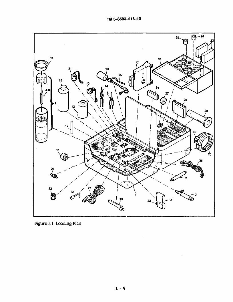
Loading Plan . . . . . . . . . . . . . . . . . . . . . . . . . . . . . .1-5Pressure Valve in Closed Position . . . . .. . . . . . . . . . . . . . . . . . 1-7Installing the Quick-Release Valve . . . . . . . . . . . . . . . . . . . . . . . . . 2-4Valve Plug in Fitting . . . . . . . . . . . . . . . . . . . . . . . . . . . . . . . . . .. . . . .2-4Removing Protective Plugs from Monitor. . . . . . . . . . . . . . . . . . . .2-5Inserting the Monitor into Sampler Base . . . . . . .. . . . . . 2-5Inserting the Bypass Hose into Sampler Base . . . . . . . . . . . . . .2-6Attaching the Remote Sampling Assembly . . . . . . . . . . . . . . . . 2-7Three-Way Valve - OFF Position . . . . . .. . . . . . . . . . . 2-8Removing Sampler Protective Cap from Quick-Release . . . . . . .2-8Valve PlugInserting Sampler Hose Nipple into Sample Valve Collar . . . . . . ...2-9Attachment of Ground Wire to Assembly . . . . . 2-10Three-Way Valve - FLUSH Position . . . . . . . . . . . . . . . . . . . . . . . ..2-11Three-Way Valve - TEST Position . . . . . . . . . . .. . . . . . . . ..2-11Replacing the Protective Cap and Plug . . . . . . . . . . . . . . . . . . . . . . . ..2-12Removing the Monitor from Sampler . . . . . . . . . . . . . . . . . . . 2-13Fitting the Monitor into the Two-Way Syringe Valve. . . . . . . . . . . .2-14Attaching the Remote Sampling Assembly . . . . .. . . . . 2-17Filling the Plastic Cylinder. . . . . . . . . . . . . . . . . . . . . . . . . 2-19Hydrometer Scale within Fuel Cap . . . . . . . . . . . . . . . . . . . 2-20Miniscus Cut Point . . . . . . . . . . . . . . . . . . . . . . . . . . . . . . . . . . 2-21Reading Corrected API Gravity, Temperature, and . . . . . . . . . . . . 2-22Relative DensityAC/Internal/External Power Setting . . . . . . . . . . . . . . . . .2-25Calibration Pad and Calibration Set Code. . . . . . . . . .. . . . . . . . 2-26Placement of Calibration Pad in Test Area Window . . . . . . . . . ..2-27Set the Light-Modulator Lever . . . . . . . . . . . . . . . . . . . . . . . . . . . 2-28Calibration Meter Lever Shaft Reading “0” . . . . . . . . . . . . . . . . . . . 2-29Removing the Outer Screw from Calibration Meter Housing... .2-30Zeroing-Out the Meter Lever . . . . . . . . . . . . . .. . . . . . . . . . . . . 2-31Removing Stainless Steel Monitor Top . . . . . . . . . . . . . . . . . . . . 2-32Inserting the Free Water Test Pad in the Monitor.. . . . . . . . . ...2-33Inserting the Monitor into Sampler Base . . . . . . . . . . . . . . . . . . . 2-34Attaching the Remote Sampling Cap and Bypass Hose . . . . . . . . . . 2-35Three-way Valve - OFF Position . . . . . . . . . . . . . . . . . . . . . . . . . . . 2-35Inserting Sampler Hose Nipple into Sample Valve Collar . . ...2-36Three-Way Valve - TEST Position . . . . . . . . . . . . . . . . . . . . . . . . . 2-37Removing the Monitor from Sampler. . . . . . . . . . . . . . . . . . . . . . . . 2-38Placement of Free-Water Pad in Test Area Window . .. . . . . . . . . . .2-39Reading the Undissolved Water Level . . . . . . . . . . . . .. . . . . . . . . 2-40
iii/ iv


TM 5-6630-218-10
Chapter 1.0 General Information
1.1 Description
The Millipore Aviation Fuel Contaminant Test Kit is a one-person, portablekit consisting of components and testing equipment capable of determining theparticulate contaminant level, API Gravity and temperature, and free watercontent in aviation fuel samples.
1.2
1.3
Scope
This manual details and illustrates the following:
a. contents of the Aviation Fuel Contaminant Test Kitb. operating proceduresc. cleaning and maintenance
Documentation
The following documents were in effect at time of invitation for bids.
Specifications:• Mil-M-7298C (TM) Manuals, Technical, Commercial EquipmentŽ Mil-M-38784B (TM)• � Mil-M-63036 (TM) (Supplements)
Standards:Ž ASTM - Dl298 - 85 - Standard Test Method for Density, Relative Density(Specific Gravity) or API Gravity of Crude Petroleum and Liquid Petroleumproducts by Hydrometer method.Ž ASTM - D2276 - 88 - Standard Test Method for Particulate Contaminationin Aviation Fuel.Ž ASTM D 3240 - 86a - Standard Method of Test for Undissolved Water inAviation Turbine Fuels.• ASTM D 3830 - 79 - Standard and Practice for Filter Membrane ColorRatings of Aviation Turbine Fuels.Ž Aviation Turbine Fuel Contamination Standards Booklet (XX6403785)included in the Aviation Fuel Contaminant Test Kit.
Equipment Specifications
Length: 54.6 centimeters (21.5 inches)Width: 13.5 centimeters (5.3 inches)Height: 41.9 centimeters (16.5 inches)Weight: not to exceed 20.4 kilograms (45 pounds)
1-1
TM 5-6630-218-10
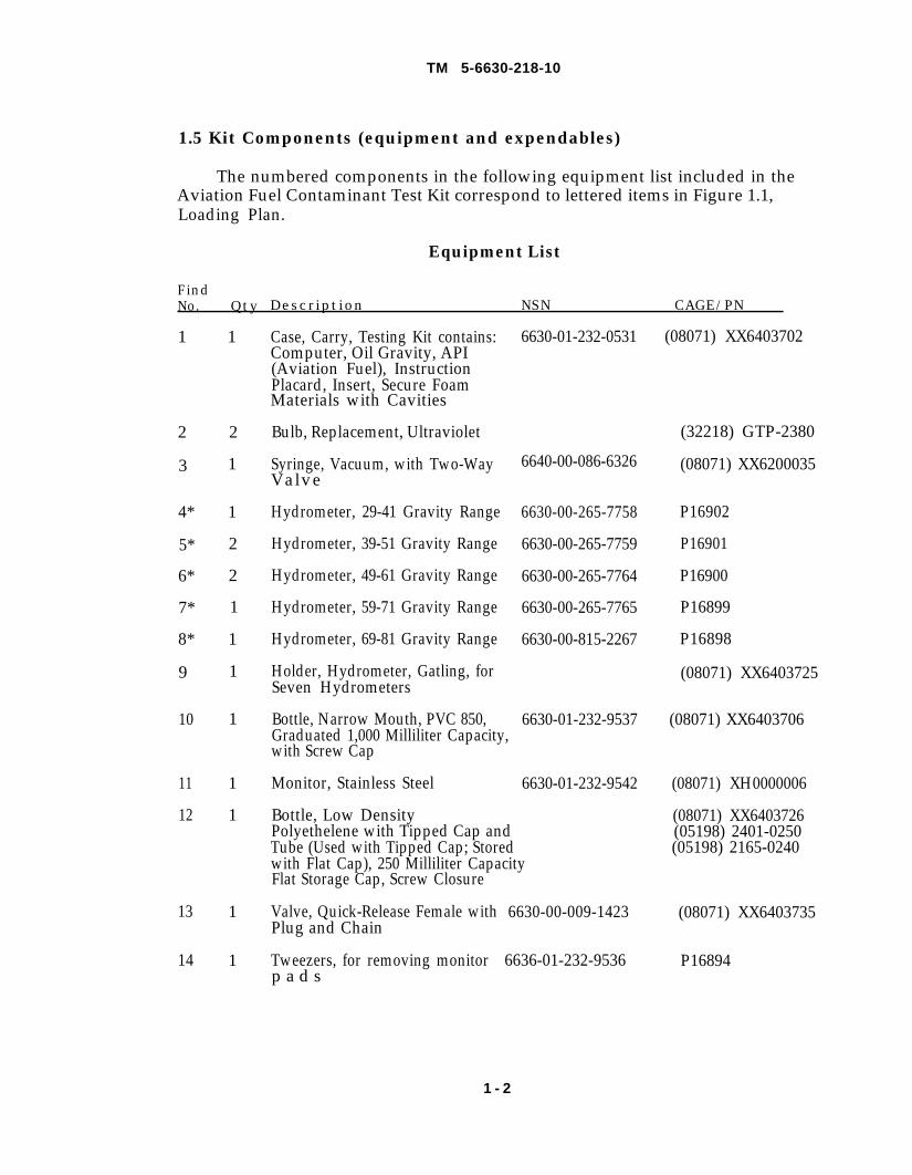
1.5 Kit Components (equipment and expendables)
The numbered components in the following equipment list included in theAviation Fuel Contaminant Test Kit correspond to lettered items in Figure 1.1,Loading Plan.
Equipment List
FindNo. Qty Description NSN CAGE/PN
1
2
3
4*
5*
6*
7*
8*
9
10
11
12
13
14
1
2
1
1
2
2
1
1
1
1
1
1
1
1
Case, Carry, Testing Kit contains:Computer, Oil Gravity, API(Aviation Fuel), InstructionPlacard, Insert, Secure FoamMaterials with Cavities
Bulb, Replacement, Ultraviolet
Syringe, Vacuum, with Two-WayValve
Hydrometer, 29-41 Gravity Range
Hydrometer, 39-51 Gravity Range
Hydrometer, 49-61 Gravity Range
Hydrometer, 59-71 Gravity Range
Hydrometer, 69-81 Gravity Range
Holder, Hydrometer, Gatling, forSeven Hydrometers
Bottle, Narrow Mouth, PVC 850,Graduated 1,000 Milliliter Capacity,with Screw Cap
Monitor, Stainless Steel
Bottle, Low DensityPolyethelene with Tipped Cap andTube (Used with Tipped Cap; Stored
6630-01-232-0531 (08071) XX6403702
6640-00-086-6326
6630-00-265-7758
6630-00-265-7759
6630-00-265-7764
6630-00-265-7765
6630-00-815-2267
6630-01-232-9537
6630-01-232-9542
with Flat Cap), 250 Milliliter CapacityFlat Storage Cap, Screw Closure
Valve, Quick-Release Female with 6630-00-009-1423Plug and Chain
Tweezers, for removing monitor 6636-01-232-9536p a d s
(32218) GTP-2380
(08071) XX6200035
P16902
P16901
P16900
P16899
P16898
(08071) XX6403725
(08071) XX6403706
(08071) XH0000006
(08071) XX6403726(05198) 2401-0250(05198) 2165-0240
(08071) XX6403735
P16894
1 - 2
TM 5-6630-218-10
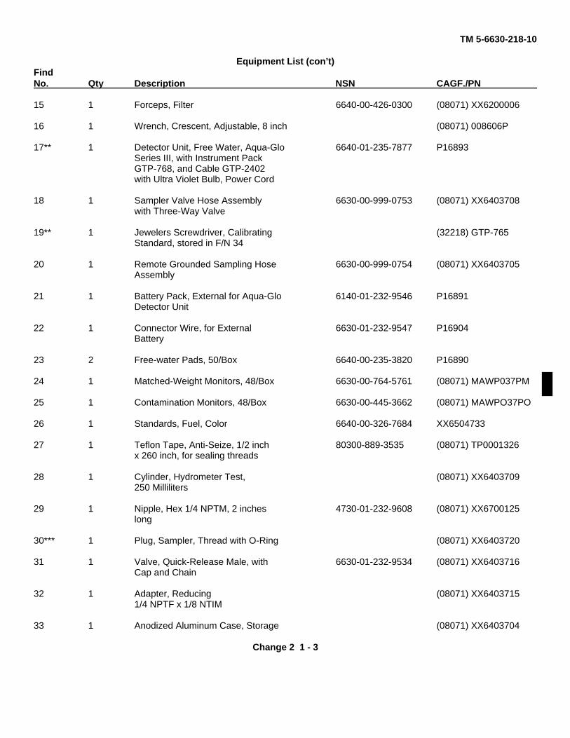
Equipment List (con’t)FindNo. Qty Description NSN CAGF./PN
15 1 Forceps, Filter 6640-00-426-0300 (08071) XX6200006
16 1 Wrench, Crescent, Adjustable, 8 inch (08071) 008606P
17** 1 Detector Unit, Free Water, Aqua-Glo 6640-01-235-7877 P16893Series III, with Instrument PackGTP-768, and Cable GTP-2402with Ultra Violet Bulb, Power Cord
18 1 Sampler Valve Hose Assembly 6630-00-999-0753 (08071) XX6403708with Three-Way Valve
19** 1 Jewelers Screwdriver, Calibrating (32218) GTP-765Standard, stored in F/N 34
20 1 Remote Grounded Sampling Hose 6630-00-999-0754 (08071) XX6403705Assembly
21 1 Battery Pack, External for Aqua-Glo 6140-01-232-9546 P16891Detector Unit
22 1 Connector Wire, for External 6630-01-232-9547 P16904Battery
23 2 Free-water Pads, 50/Box 6640-00-235-3820 P16890
24 1 Matched-Weight Monitors, 48/Box 6630-00-764-5761 (08071) MAWP037PM
25 1 Contamination Monitors, 48/Box 6630-00-445-3662 (08071) MAWPO37PO
26 1 Standards, Fuel, Color 6640-00-326-7684 XX6504733
27 1 Teflon Tape, Anti-Seize, 1/2 inch 80300-889-3535 (08071) TP0001326x 260 inch, for sealing threads
28 1 Cylinder, Hydrometer Test, (08071) XX6403709250 Milliliters
29 1 Nipple, Hex 1/4 NPTM, 2 inches 4730-01-232-9608 (08071) XX6700125long
30*** 1 Plug, Sampler, Thread with O-Ring (08071) XX6403720
31 1 Valve, Quick-Release Male, with 6630-01-232-9534 (08071) XX6403716Cap and Chain
32 1 Adapter, Reducing (08071) XX64037151/4 NPTF x 1/8 NTIM
33 1 Anodized Aluminum Case, Storage (08071) XX6403704
Change 2 1 - 3
TM 5-6630-218-10
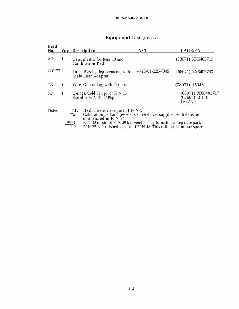
Equipment List (con’t.)
FindNo. Qty Description NSN CAGE/PN
34 1 Case, plastic, for Item 19 and (08071) XX6403719Calibration Pad
35**** 1 Tube, Plastic, Replacement, with 4720-01-229-7045 (08071) XX6403780Male Luer Adapter
36 1 Wire, Grounding, with Clamps (08071) 15043
37 1 O-rings, Cold Temp, for F/N 13 (08071) XX6403717Stored in F/N 34, 3/Pkg (02697) 2-110,
L677-70
Notes: *1 . Hydrometers are part of F/N 9.**2. Calibration pad and jeweler’s screwdriver supplied with detector
unit, stored in F/N 34.***3. F/N 30 is part of F/N 20 but vendor may furnish it as separate part.
****4. F/N 35 is furnished as part of F/N 18. This call-out is for one spare
1-4
1-5
Figure 1.1
TM 5-6630-218-10
TM 5-6630-218-10
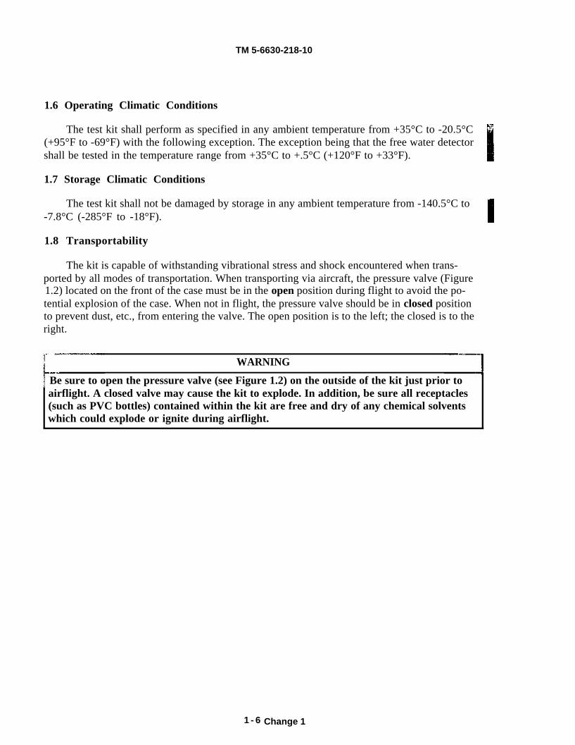
1.6 Operating Climatic Conditions
The test kit shall perform as specified in any ambient temperature from +35°C to -20.5°C (+95°F to -69°F) with the following exception. The exception being that the free water detectorshall be tested in the temperature range from +35°C to +.5°C (+120°F to +33°F).
1.7 Storage Climatic Conditions
The test kit shall not be damaged by storage in any ambient temperature from -140.5°C to-7.8°C (-285°F to -18°F).
1.8 Transportability
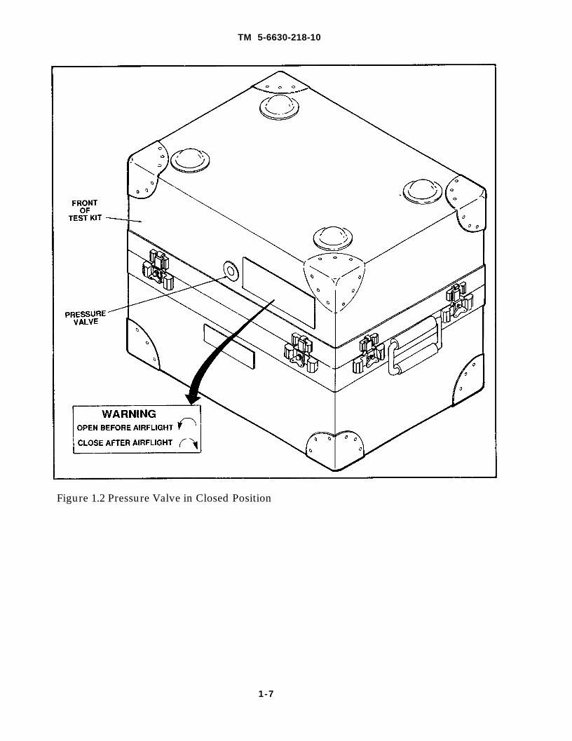
The kit is capable of withstanding vibrational stress and shock encountered when trans-ported by all modes of transportation. When transporting via aircraft, the pressure valve (Figure1.2) located on the front of the case must be in the open position during flight to avoid the po-tential explosion of the case. When not in flight, the pressure valve should be in closed positionto prevent dust, etc., from entering the valve. The open position is to the left; the closed is to theright.
WARNING
Be sure to open the pressure valve (see Figure 1.2) on the outside of the kit just prior toairflight. A closed valve may cause the kit to explode. In addition, be sure all receptacles(such as PVC bottles) contained within the kit are free and dry of any chemical solventswhich could explode or ignite during airflight.
1 - 6 Change 1
TM 5-6630-218-10
Figure 1.2 Pressure Valve in Closed Position
1-7

TM 5-6630-218-10
Chapter 2.0 Operating Instructions
2.1 Introduction
This chapter contains information on collecting and testing aviation fuel forsolid contaminants using the Particulate Contaminants Test (as outlined inSection 2.3), for specific gravity using the API Gravity Test (as outlined in Section2.4), and for free water content using the Undissolved Water Test (as outlined inSection 2.5).
2.1.1 Applicable Documents
Standards:• ASTM D 1298-85 - Standard Test Method for Density, Relative Density(Specific Gravity) or API Gravity of Crude Petroleum and Liquid Petroleumproducts by Hydrometer method.Ž ASTM D 2276-88 - Standard Test, Method for ParticulateContamination in Aviation Fuel.• ASTM D 3240-86a - Standard Method of Test for Undissolved Water inAviation Turbine Fuels.Ž ASTM D 3830-79 - Standard and Practice for Filter Membrane ColorRatings or Aviation Turbine Fuels.• Aviation Turbine Fuel Contamination Standards Booklet (XX6403785)included in the Aviation Fuel Contaminant Test Kit.
2.2 Aviation Fuel Sample
The aviation fuel sample is the sample required for colormetric andgravimetric Particulate Contaminant Test Procedure--ASTM D 2276- 88 the APIGravity Test Procedure--ASTM D 1298-85 and the Undissolved Water TestProcedure--ASTM D 3240-86a.
2-1
TM 5-6630-218-10
Using the site-established method of collection, collect a one-gallon (3.8 liter)sample of aviation fuel for each of three tests. Contain the sample in an approvedsafety receptacle which holds at least 5 gallons (19 liters). Wear gloves andprotective eyewear. For consistency, the collection method should be thesame for all three tests.
2.3 Operating Instructions for Particulate Contaminants Test
Particulate matter in aviation fuel must be minimized to avoid filterplugging and other operational problems. The Particulate Contaminants Testallows you to measure and monitor the amount of particulate matter present inthe aviation fuel sample. (Testing methodology is in accordance with ASTM D2276-88 .)
This section contains information on the required equipment andexpendable needed to perform the test, the two methods of particulatecontaminant analysis, and the test operating procedures.
2.3.1 Required Equipment and Expendable (See Figure 1.1, page 1-5,Aviation Fuel Contaminant Test Kit Loading Plan)
Equipment List
Find No Description NSN(CAGE)P/N
313
141618
2 0
263 6
Syringe, Vacuum, with Two-Way ValveValve, Quick-Release Female with Plugand ChainTweezers, for removing monitor padsWrench, Crescent, Adjustable, 8 inchSampler Valve Hose Assembly,with Three-Way ValveRemote Grounded Sampling HoseAssemblyStandards, Fuel, ColorWire, Grounding, with Clamps
6640-00-086-63266630-00-009-1423
6636-01-232-9536(08071)008606P6630-00-999-0753
6630-00-999-0754
6640-00-326-7684(08071)15043
Expendables List
Find No Description NSN(CAGE)P/N
24 Matched-Weight Monitors, 48/Box 6630-00-764-57612 5 Contamination Monitors, 48/Box 6630-00-445-36622 7 Teflon Tape, Anti-Seize, 1/2 inch x 260 inch, 8030-00-889-3535
for sealing threads5-Gallon Receptacle, for fuel collection as site specifiedand drainageProtective Wrapping, for shipping as site specifiedmonitor to laboratory
2-2
TM 5-6630-218-10
2.3.1.1 Methods for Particulate Contaminants Testing
Measuring the amount of particulate contaminants present in the aviationfuel sample can be accomplished using one or both, of two test methods: theColor Comparator Method and/or the Gravimetric Method.
The Color Comparator Method can be performed at the test location withvisual analysis; this method is a quick way to check fuel and is recommended foran initial check of the sample’s particulate contaminant level. If color comparatortest results are marginal or unacceptable, perform a gravimetric test. TheGravimetric Method involves measurement of contaminants through off-sitelaboratory analysis and is a more exact method.
The Color Comparator Method and Gravimetric Method tests areaccomplished in nine procedural steps (as outlined below and on the test kitplacard): the first eight steps are the same for both methods. The ninth step orthe analysis step varies according to the test method: when using the ColorComparator Method, analysis of the sample is made using the Aviation TurbineFuel Contamination Standards booklet included in the test kit (see booklet formore detail). When testing the sample gravimetrically (using the GravimetricMetiod), you must ship the sample to the nearest approved laboratory foranalysis.
All parts and tools referred to in the following steps can be identified inFigure 1.1, page 1-5, or on the test kit placard (see Loading Plan).
2.3.2 Installing the Quick-Release Valve
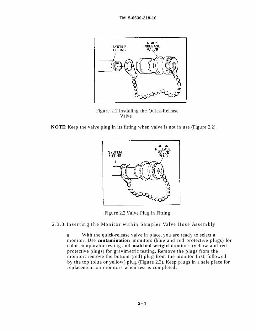
Using the eight-inch adjustable wrench, attach the quick-release valve tothe designated point on the system (this will vary with the type of equipment youare using, however, attach the valve in a horizontal position on the system or atthe top of the system to allow for proper flushing). See Figure 2.1.
Make sure that the pressure in system does not exceed 100 psi.
2-3
TM 5-6630-218-10
Figure 2.1 Installing the Quick-ReleaseValve
NOTE: Keep the valve plug in its fitting when valve is not in use (Figure 2.2).
Figure 2.2 Valve Plug in Fitting
2.3.3 Inserting the Monitor within Sampler Valve Hose Assembly
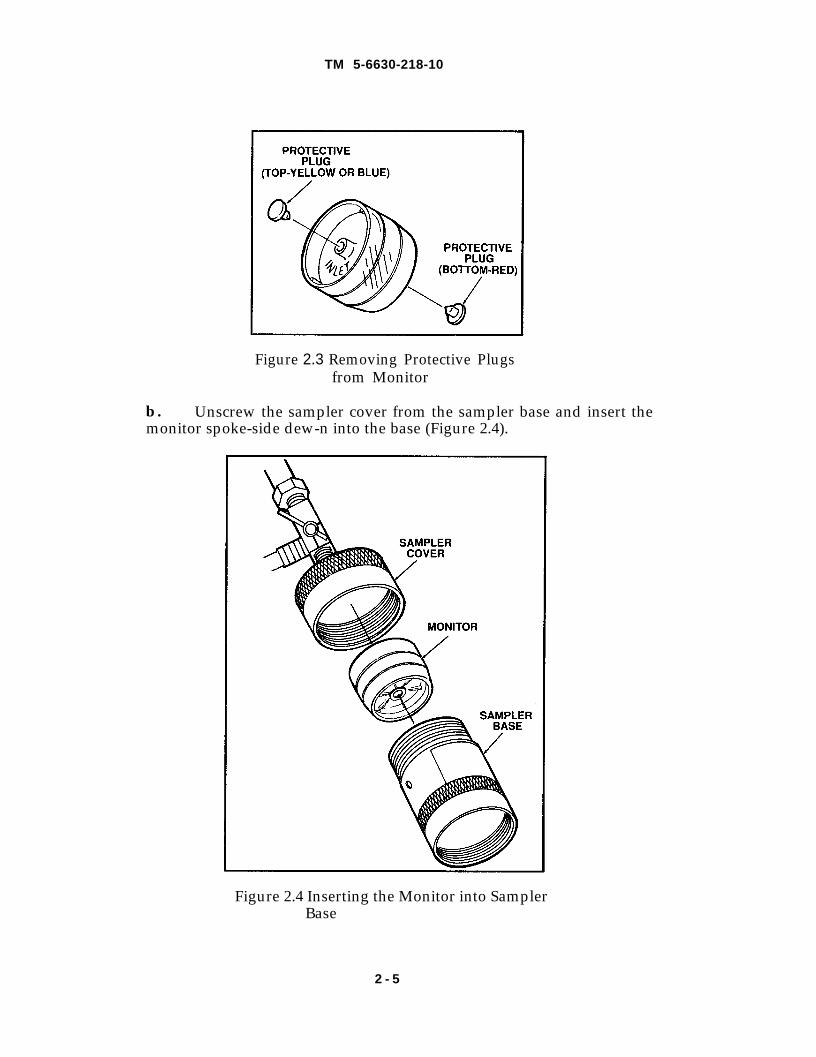
a. With the quick-release valve in place, you are ready to select amonitor. Use contamination monitors (blue and red protective plugs) forcolor comparator testing and matched-weight monitors (yellow and redprotective plugs) for gravimetric testing. Remove the plugs from themonitor: remove the bottom (red) plug from the monitor first, followedby the top (blue or yellow) plug (Figure 2.3). Keep plugs in a safe place forreplacement on monitors when test is completed.
2 - 4
TM 5-6630-218-10
Figure 2.3 Removing Protective Plugsfrom Monitor
b. Unscrew the sampler cover from the sampler base and insert themonitor spoke-side dew-n into the base (Figure 2.4).
Figure 2.4 Inserting the Monitor into SamplerBase
2 - 5
TM 5-6630-218-10
2.3.4 Assembling the Sampler Valve Hose Assembly
a. Insert the sampler base (with monitor in place) into the samplercover and screw the two pieces together to a snug hand-tightness.
CAUTIONDo not over-tighten or damage to the monitor or membrane may occur.
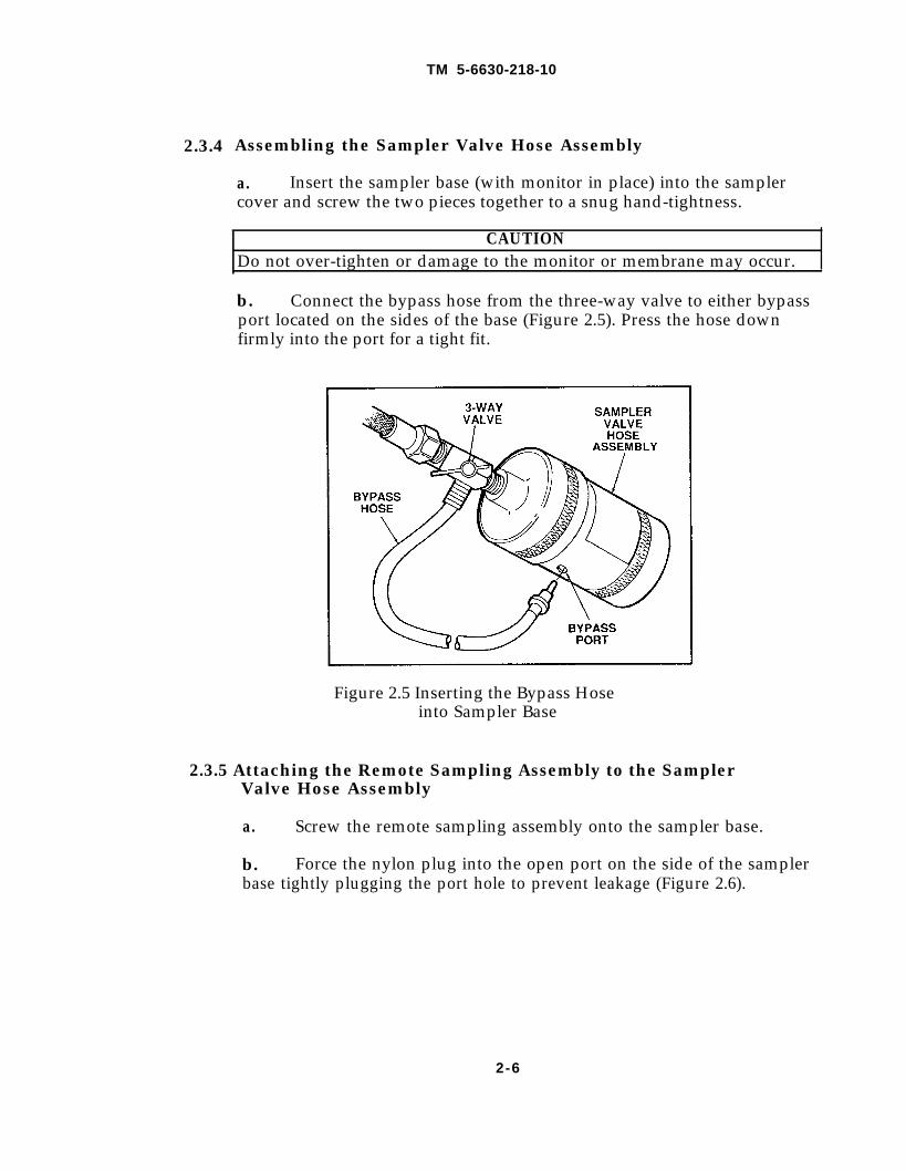
b. Connect the bypass hose from the three-way valve to either bypassport located on the sides of the base (Figure 2.5). Press the hose downfirmly into the port for a tight fit.
Figure 2.5 Inserting the Bypass Hoseinto Sampler Base
2.3.5 Attaching the Remote Sampling Assembly to the SamplerValve Hose Assembly
a. Screw the remote sampling assembly onto the sampler base.
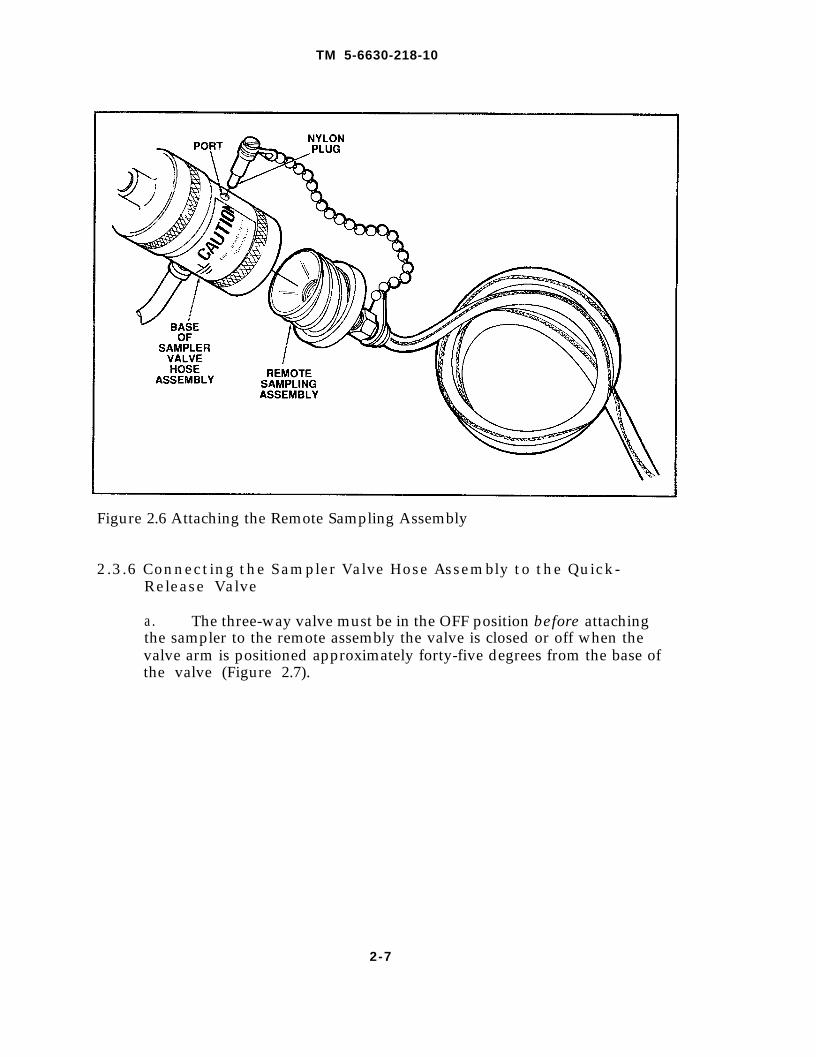
b. Force the nylon plug into the open port on the side of the samplerbase tightly plugging the port hole to prevent leakage (Figure 2.6).
2-6
TM 5-6630-218-10
Figure 2.6 Attaching the Remote Sampling Assembly
2.3.6 Connecting the Sampler Valve Hose Assembly to the Quick-Release Valve
a. The three-way valve must be in the OFF position before attachingthe sampler to the remote assembly the valve is closed or off when thevalve arm is positioned approximately forty-five degrees from the base ofthe valve (Figure 2.7).
2-7
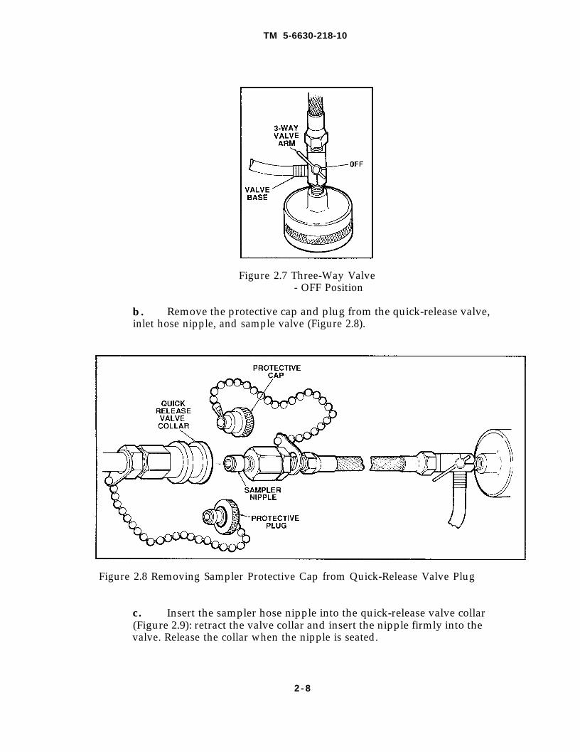
TM 5-6630-218-10
Figure 2.7 Three-Way Valve- OFF Position
b. Remove the protective cap and plug from the quick-release valve,inlet hose nipple, and sample valve (Figure 2.8).
Figure 2.8 Removing Sampler Protective Cap from Quick-Release Valve Plug
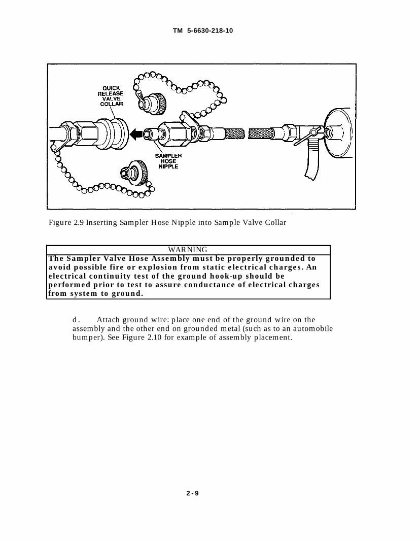
c. Insert the sampler hose nipple into the quick-release valve collar(Figure 2.9): retract the valve collar and insert the nipple firmly into thevalve. Release the collar when the nipple is seated.
2 - 8
TM 5-6630-218-10
Figure 2.9 Inserting Sampler Hose Nipple into Sample Valve Collar
WARNINGThe Sampler Valve Hose Assembly must be properly grounded toavoid possible fire or explosion from static electrical charges. Anelectrical continuity test of the ground hook-up should beperformed prior to test to assure conductance of electrical chargesfrom system to ground.
d. Attach ground wire: place one end of the ground wire on theassembly and the other end on grounded metal (such as to an automobilebumper). See Figure 2.10 for example of assembly placement.
2 - 9
TM 5-6630-218-10
2.3.7
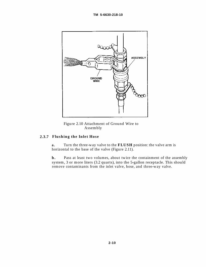
Figure 2.10 Attachment of Ground Wire toAssembly
Flushing the Inlet Hose
a. Turn the three-way valve to the FLUSH position: the valve arm ishorizontal to the base of the valve (Figure 2.11).
b. Pass at least two volumes, about twice the containment of the assemblysystem, 3 or more liters (3.2 quarts), into the 5-gallon receptacle. This shouldremove contaminants from the inlet valve, hose, and three-way valve.
2-10
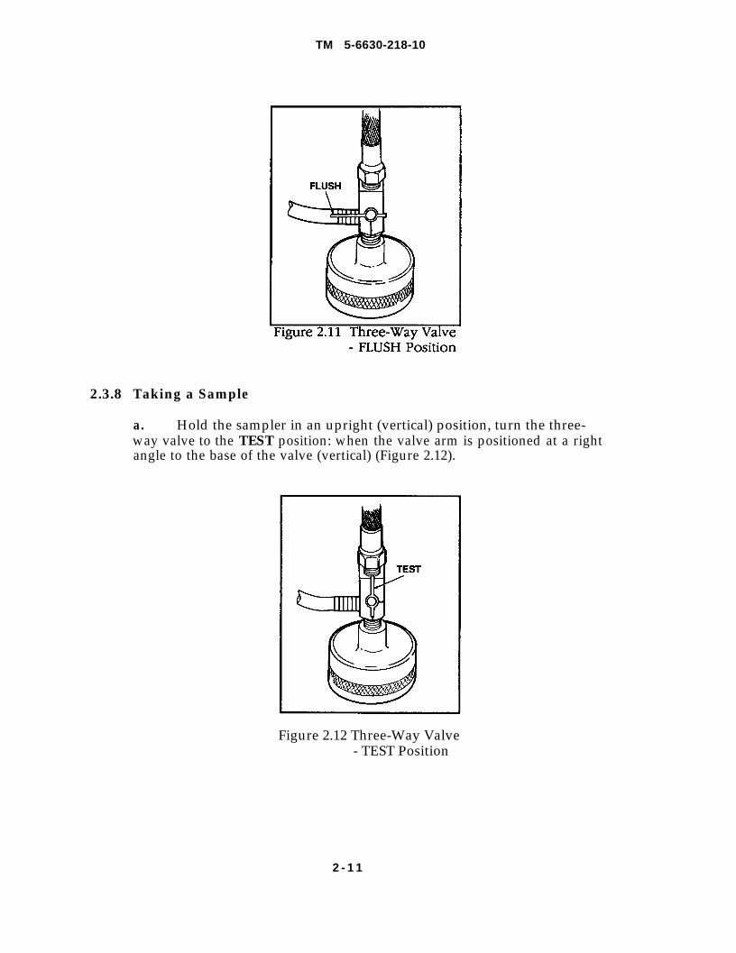
Figure 2.11
TM 5-6630-218-10
2.3.8 Taking a Sample
a. Hold the sampler in an upright (vertical) position, turn the three-way valve to the TEST position: when the valve arm is positioned at a rightangle to the base of the valve (vertical) (Figure 2.12).
Figure 2.12 Three-Way Valve- TEST Position
2 - 1 1
TM 5-6630-218-10
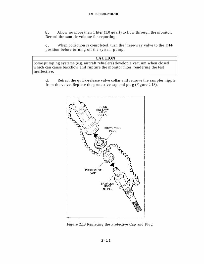
b. Allow no more than 1 liter (1.0 quart) to flow through the monitor.Record the sample volume for reporting.
c . When collection is completed, turn the three-way valve to the OFFposition before turning off the system pump.
CAUTIONSome pumping systems (e.g. aircraft refuelers) develop a vacuum when closedwhich can cause backflow and rupture the monitor filter, rendering the testineffective.
d. Retract the quick-release valve collar and remove the sampler nipplefrom the valve. Replace the protective cap and plug (Figure 2.13).
Figure 2.13 Replacing the Protective Cap and Plug
2 - 1 2
TM 5-6630-218-10
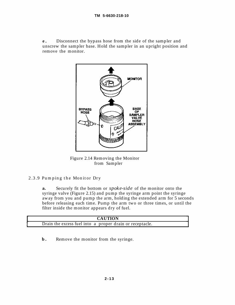
e . Disconnect the bypass hose from the side of the sampler andunscrew the sampler base. Hold the sampler in an upright position andremove the monitor.
Figure 2.14 Removing the Monitorfrom Sampler
2.3.9 Pumping the Monitor Dry
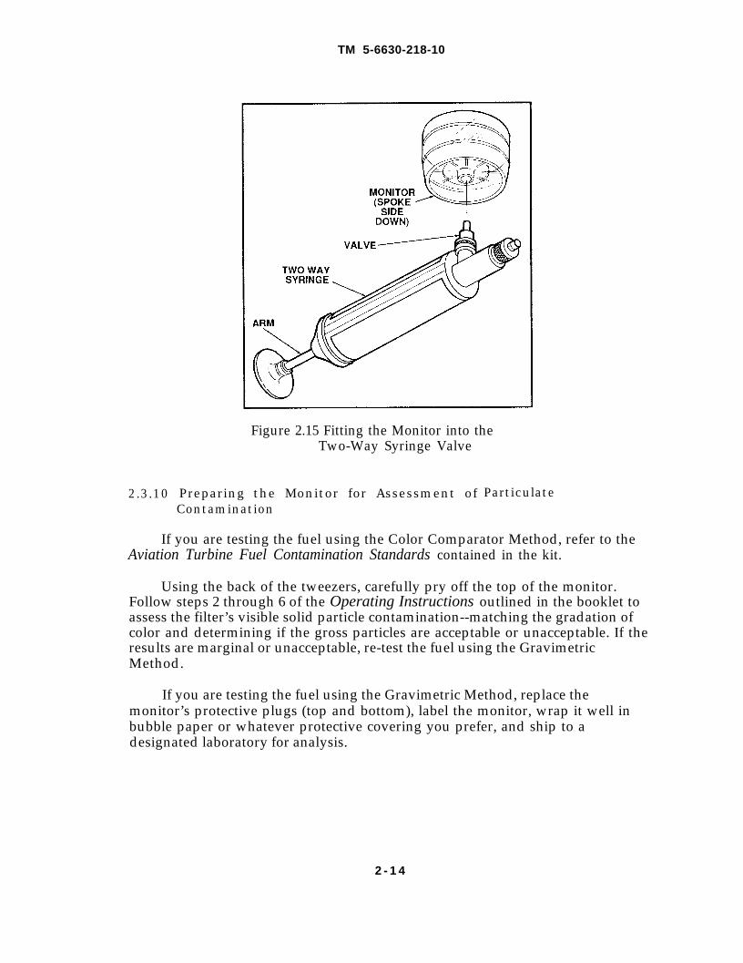
a. Securely fit the bottom or spoke-side of the monitor onto thesyringe valve (Figure 2.15) and pump the syringe arm point the syringeaway from you and pump the arm, holding the extended arm for 5 secondsbefore releasing each time. Pump the arm two or three times, or until thefilter inside the monitor appears dry of fuel.
CAUTIONDrain the excess fuel into a proper drain or receptacle.
b . Remove the monitor from the syringe.
2 - 1 3
TM 5-6630-218-10
2.3.10
Figure 2.15 Fitting the Monitor into theTwo-Way Syringe Valve
Preparing the Monitor for Assessment of ParticulateContamination
If you are testing the fuel using the Color Comparator Method, refer to theAviation Turbine Fuel Contamination Standards contained in the kit.
Using the back of the tweezers, carefully pry off the top of the monitor.Follow steps 2 through 6 of the Operating Instructions outlined in the booklet toassess the filter’s visible solid particle contamination--matching the gradation ofcolor and determining if the gross particles are acceptable or unacceptable. If theresults are marginal or unacceptable, re-test the fuel using the GravimetricMethod.
If you are testing the fuel using the Gravimetric Method, replace themonitor’s protective plugs (top and bottom), label the monitor, wrap it well inbubble paper or whatever protective covering you prefer, and ship to adesignated laboratory for analysis.
2 - 1 4
2.4 Operating Instructions
TM 5-6630-218-10
for API Gravity Tests
Testing for specific or API gravity and relative density is necessary tocontrol the quality and volume levels of the fuel. The measurement of fueltemperature is also required to minimize volume correction errors. The testingmethodology outlined in this section is in accordance with ASTM StandardD 1298 - 85
This section contains information on the required equipment andexpendable needed to perform the tests and the test operating procedures.
2.4.1 Required Equipment and Expendable (See Figure 1.1, page 1-5Aviation Fuel Contaminant Test Kit Loading Plan)
Equipment List
Find No: Desc ription NSN/(CAG E)P/N
1 0 Bottle, Narrow Mouth, PVC 850, 6630-01-232-9537Graduated 1,000 Milliliter Capacity,with Screw Cap
1 3 Valve, Quick-Release, Female with 6630-00-009-1423Plug and Chain
1 6 Wrench, Crescent, Adjustable, 8 inch (08071) 008606P1 8 Sampler Valve Hose Assembly, 6630-00-999-0753
with Three-Way ValveCylinder, Hydrometer Test, 250 Milliliters (08071) XX6403709
28 Wire, Grounding with Clamps (08071) 1504336
Expendables
Find No: Description
List
NSN/(CAG E)P/N
27 Teflon Tape, Anti-Seize, 1/2 inch x 8030-00-889-3535260 inch, for sealing threads5-gallon Receptacle, for fuel collection as site specifiedand drainagePaper Towels, for blotting as site specified
2 - 1 5

TM 5-6630-218-10
2.4.1.1 Method for API Gravity Testing
Collect approximately two volumes--100 milliliters (3.4 ounces) of fuelsample. Balance the sample to a prescribed temperature (for example, 15°C or47°F) and transfer the sample to a cylinder prepared at approximately the sametemperature.
Select an appropriate hydrometer and lower it into the cylinder. Allow thehydrometer to settle. After temperature equilibrium is attained (approximately 5minutes), take a temperature reading from the hydrometer scale and record itaccording to site procedure.
All parts and tools referred to in the following steps can be identified inFigure 1.1, page 1-5, or on the test kit placard (see Loading Plan).
2.4.2 Installing the Quick-Release Valve
Follow the procedure for installing the quick-release valve as described inSection 2.3.2. Refer to Figure 2.1.
CAUTIONMake sure that the pressure in system does not exceed 100 psi.
2.4.3 Assembling the Sampler Valve Hose Assembly
Follow the procedure for assembling the sampler valve hose assembly asdescribed in Section 2.3.4. Refer to Figure 2.5.
CAUTIONDo not over-tighten or damage to the monitor or membrane might occur.
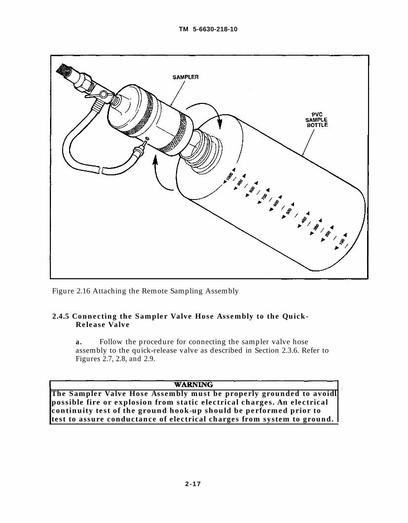
2.4.4 Attaching theAssembly
Screw the PVC(Figure 2.16).
PVC Sample Bottle to the Remote Sampling
sample bottle mouth onto the remote sampling assembly
2-16
TM 5-6630-218-10
Figure 2.16 Attaching the Remote Sampling Assembly
2.4.5 Connecting the Sampler Valve Hose Assembly to the Quick-Release Valve
a. Follow the procedure for connecting the sampler valve hoseassembly to the quick-release valve as described in Section 2.3.6. Refer toFigures 2.7, 2.8, and 2.9.
The Sampler Valve Hose Assembly must be properly grounded to avoidpossible fire or explosion from static electrical charges. An electricalcontinuity test of the ground hook-up should be performed prior totest to assure conductance of electrical charges from system to ground.
2-17
2.4.6
TM 5-6630-218-10
b. Attach ground wire: place one end of the ground wire on theassembly and the other end on grounded metal (such as to an automobilebumper). See Figure 2.10 for example of assembly placement.
Flushing the Inlet Hose
If one or all test procedures are performed at the same time(within the same hour), re-flushing the lines is not required. However, ifthe system has not been flushed, do not use the PVC bottle to contain the sample,but rather follow the procedure for flushing the inlet hose as described in Section2.3.7. Refer to Figure 2.11. Allow sufficient quantity of fuel to flow through thebypass tubing to flush entrained contaminants from the inlet valve, hose, andthree-way valve. Discard approximately two times the required test volume orapproximately 200 milliliters (7.0 ounces).
2.4.7 Taking a Sample
a. Hold the sampler upright and turn the three-way valve to the TESTposition (Figure 2.12).
b. Collect enough fuel to fill the PVC sample bottle - no more than 1liter (1.0 quart).
c. When collection is completed, turn the three-way valve to the OFFposition (Figure 2.7) before turning off the system pump.
d. Retract the quick-release valve collar; remove the sampler nipplefrom the valve and replace the protective cap and plug (Figure 2.13).
e. Carefully remove the PVC sample bottle from the sampler.
2.4.8 Determining the API Gravity and Temperature
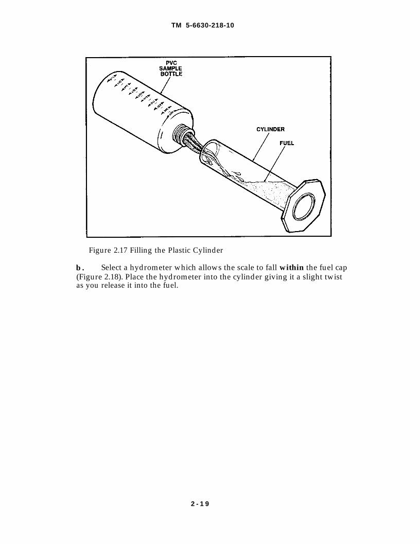
a. Fill the clear plastic cylinder half-full with fuel--pour the fuel at anangle to minimize air entrapment (Figure 2.17).
2 - 1 8
TM 5-6630-218-10
Figure 2.17 Filling the Plastic Cylinder
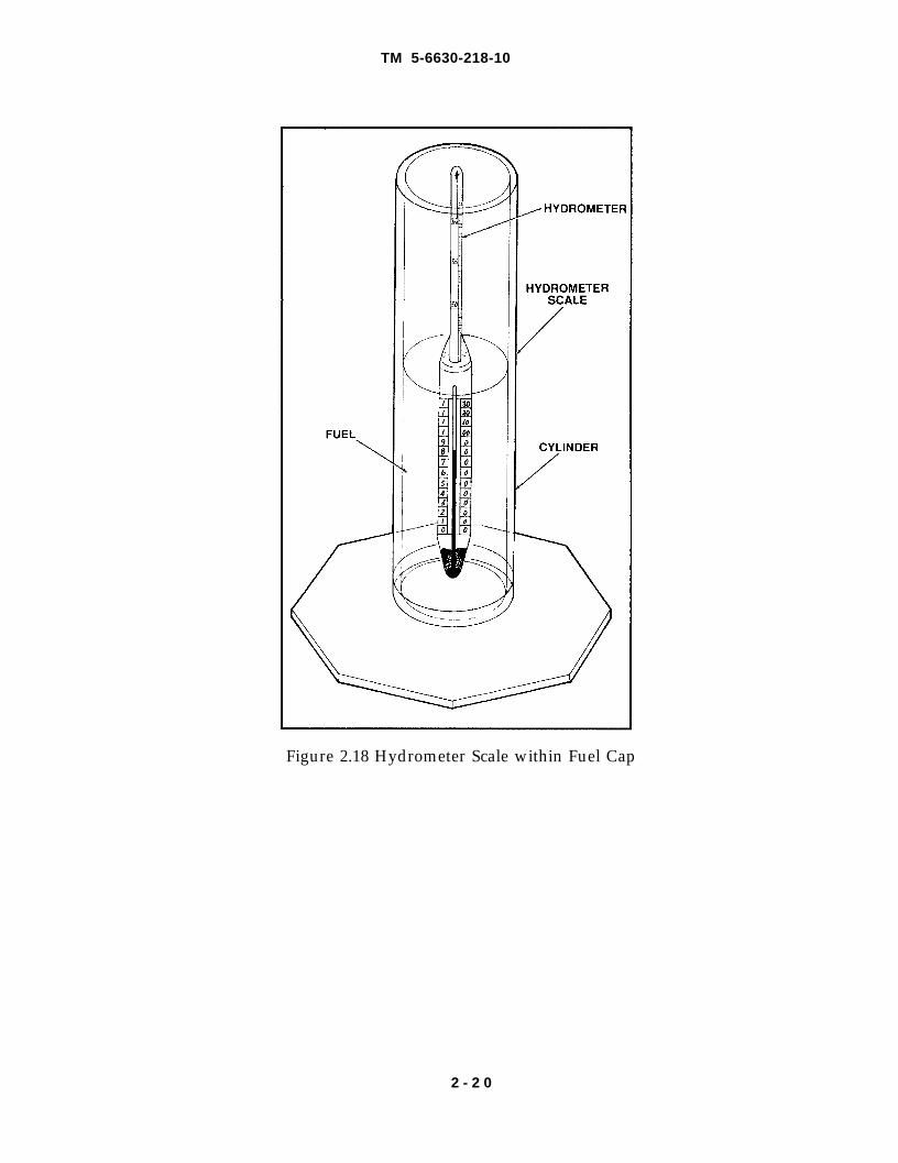
b . Select a hydrometer which allows the scale to fall within the fuel cap(Figure 2.18). Place the hydrometer into the cylinder giving it a slight twistas you release it into the fuel.
2 - 1 9
TM 5-6630-218-10
Figure 2.18 Hydrometer Scale within Fuel Cap
2 - 2 0
TM 5-6630-218-10
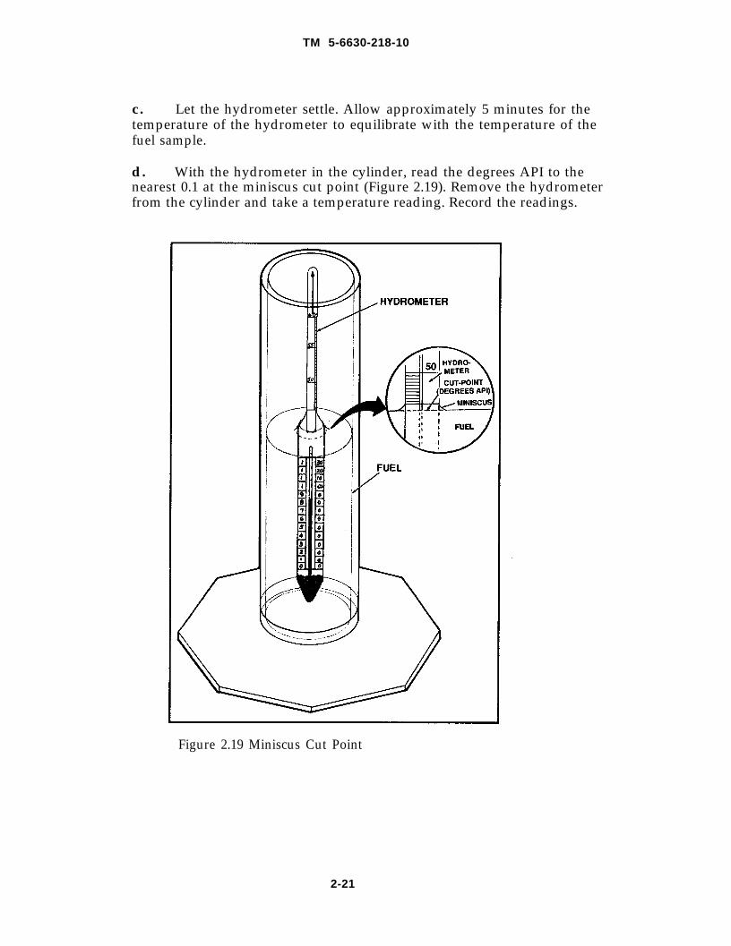
c . Let the hydrometer settle. Allow approximately 5 minutes for thetemperature of the hydrometer to equilibrate with the temperature of thefuel sample.
d. With the hydrometer in the cylinder, read the degrees API to thenearest 0.1 at the miniscus cut point (Figure 2.19). Remove the hydrometerfrom the cylinder and take a temperature reading. Record the readings.
Figure 2.19 Miniscus Cut Point
2-21
2.4.9 Finding the CorrectedDensity
TM 5-6630-218-10
API Gravity, Temperature, and Relative
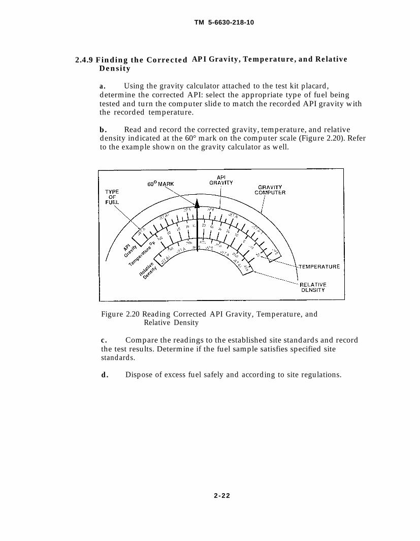
a. Using the gravity calculator attached to the test kit placard,determine the corrected API: select the appropriate type of fuel beingtested and turn the computer slide to match the recorded API gravity withthe recorded temperature.
b. Read and record the corrected gravity, temperature, and relativedensity indicated at the 60° mark on the computer scale (Figure 2.20). Referto the example shown on the gravity calculator as well.
Figure 2.20 Reading Corrected API Gravity, Temperature, andRelative Density
c. Compare the readings to the established site standards and recordthe test results. Determine if the fuel sample satisfies specified sitestandards.
d. Dispose of excess fuel safely and according to site regulations.
2-22
TM 5-6630-218-10
2.5 Operating Instructions for Undissolved Water Test
Testing for undissolved (free) water is necessary to control the growth ofMicroorganisms and the subsequent corrosion caused by such microorganisms inaircraft tanks. In addition, undissolved water testing is essential to prevent filtersfrom icing in the fuel system. The testing methodology outlined in this sectiondetermines the quantity of water in parts per million (ppm) present in a 500milliliter (17.0 ounce) fuel sample and is in accordance with ASTM StandardD 3240 - 86a.
This section contains information on the test operating procedures and therequired equipment and expendable needed to perform the tests.
2.5.1 Required Equipment and Expendable (See Figure 1.1, page 1-5,Aviation Fuel Contaminant Test Kit Loading Plan)
Equipment List
Find No Description NSN/(CAGE) /NP
10
1 8
19
2 0
36
Bottle, Narrow Mouth, PVC 850,Graduated 1,000 Milliliter Capacity,with Screw CapMonitor, Stainless SteelValve, Quick-Release Female with Plugand ChainTweezers, for removing monitor padsWrench, Crescent, Adjustable, 8 inchDetector Unit, Free Water, Aqua-GloSeries III, with Instrument Pack GTP-768,and Cable GTP-2402 with Ultra -Violet Bulb,Power CordSampler Valve Hose Assembly, withThree-Way ValveJeweler's Screwdriver, Calibrating Standard,stored in F/N 34Remote Grounded Sampling HoseAssemblyWire, Grounding, with Clamps
6630-01-232-9537
6630-01-232-95426630-00-009-1423
6636-01-232-9536(08071) 008606P6640-01-235-7877
6630-00-999-0753
(32218) GTP-765
6630-00-999-0754
(08071) 15043
Expendables List
Find No Description NSN/(CAGE)P/N
23 Free-Water Pads, 50/Box 6640-00-235-382027 Teflon Tape, Anti-Seize, 1/2 inch x 260 inch, 8030-00-889-3535
for sealing threadsPaper Towels, for blotting as site specified
2-23
Figure 2.21
TM 5-6630-218-10
2.5.1.1 Method for Undissolved Water Testing
Undissolved water in the fuel sample will react with the free-water pad dyefor detection and measurement with the Aqua-Glo® Water Detector.
Collect a 500 milliliter (17.0 ounce) sample of fuel. Pass the fuel samplethrough the sampler with the free-water test pad contained within the stainlesssteel monitor. Remove the free-water test pad from the monitor and blot drybetween paper towels. Insert the free-water test pad into the Aqua-Glo WaterDectector and read and record ppm of water.
All parts and tools referred to in the following steps can be identified inFigure 1.1, page 1-5, or on the test kit placard (see Loading Plan).
2.5.1.2 Calibrating the Aqua-Glo Water Detector
2 - 2 4
TM 5-6630-218-10
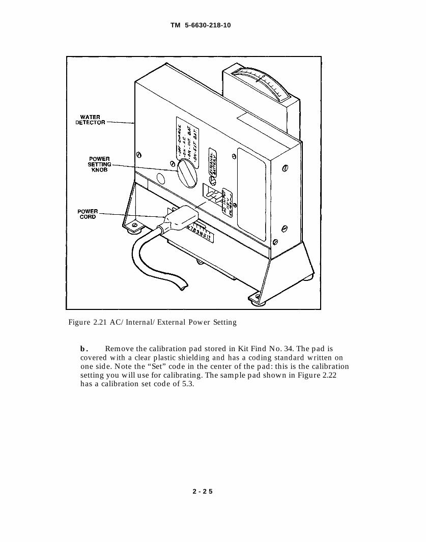
Figure 2.21 AC/Internal/External Power Setting
b. Remove the calibration pad stored in Kit Find No. 34. The pad iscovered with a clear plastic shielding and has a coding standard written onone side. Note the “Set” code in the center of the pad: this is the calibrationsetting you will use for calibrating. The sample pad shown in Figure 2.22has a calibration set code of 5.3.
2 - 2 5
TM 5-6630-218-10
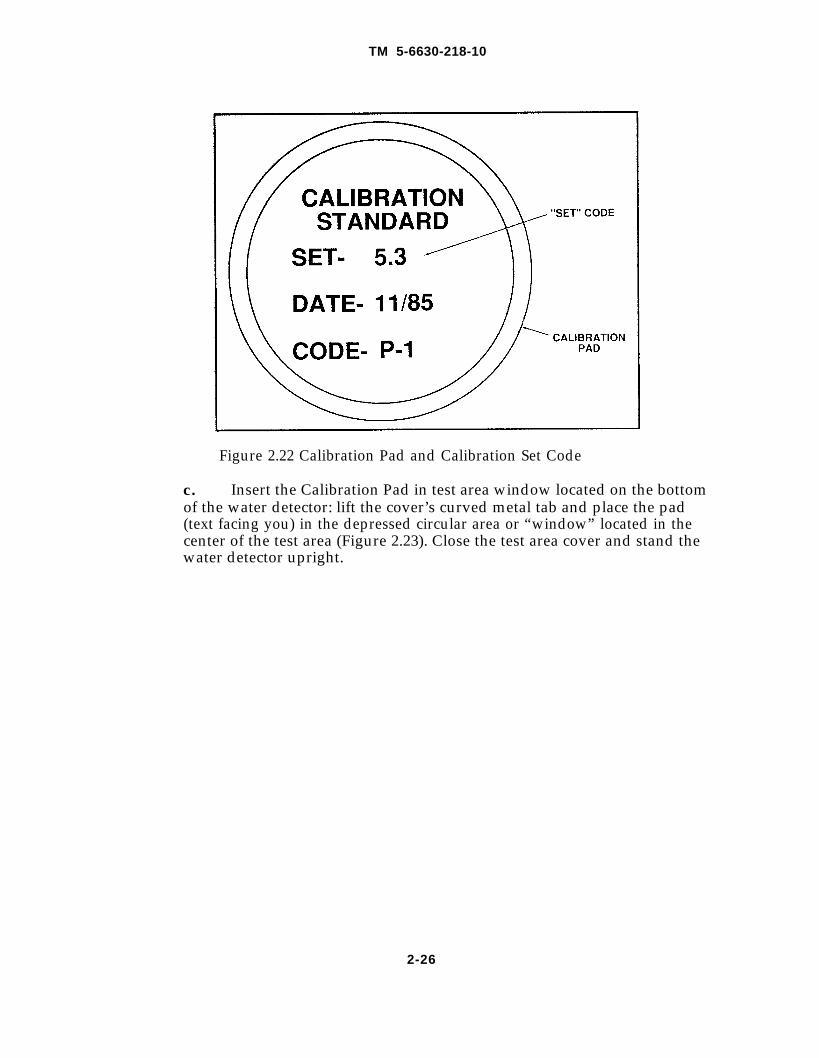
Figure 2.22 Calibration Pad and Calibration Set Code
c. Insert the Calibration Pad in test area window located on the bottomof the water detector: lift the cover’s curved metal tab and place the pad(text facing you) in the depressed circular area or “window” located in thecenter of the test area (Figure 2.23). Close the test area cover and stand thewater detector upright.
2-26
TM 5-6630-218-10
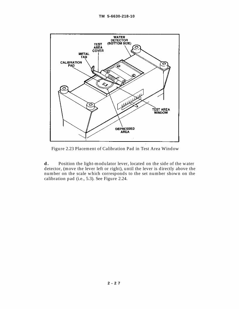
Figure 2.23 Placement of Calibration Pad in Test Area Window
d. Position the light-modulator lever, located on the side of the waterdetector, (move the lever left or right), until the lever is directly above thenumber on the scale which corresponds to the set number shown on thecalibration pad (i.e., 5.3). See Figure 2.24.
2 - 2 7
TM 5-6630-218-10
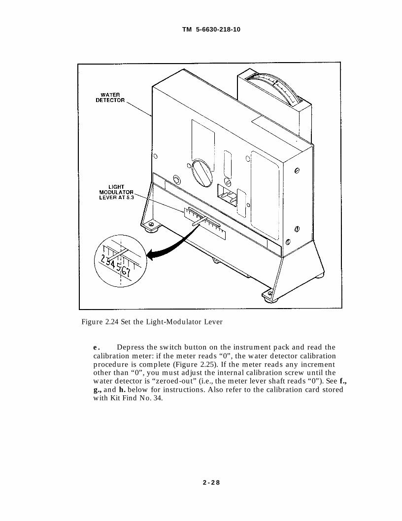
Figure 2.24 Set the Light-Modulator Lever
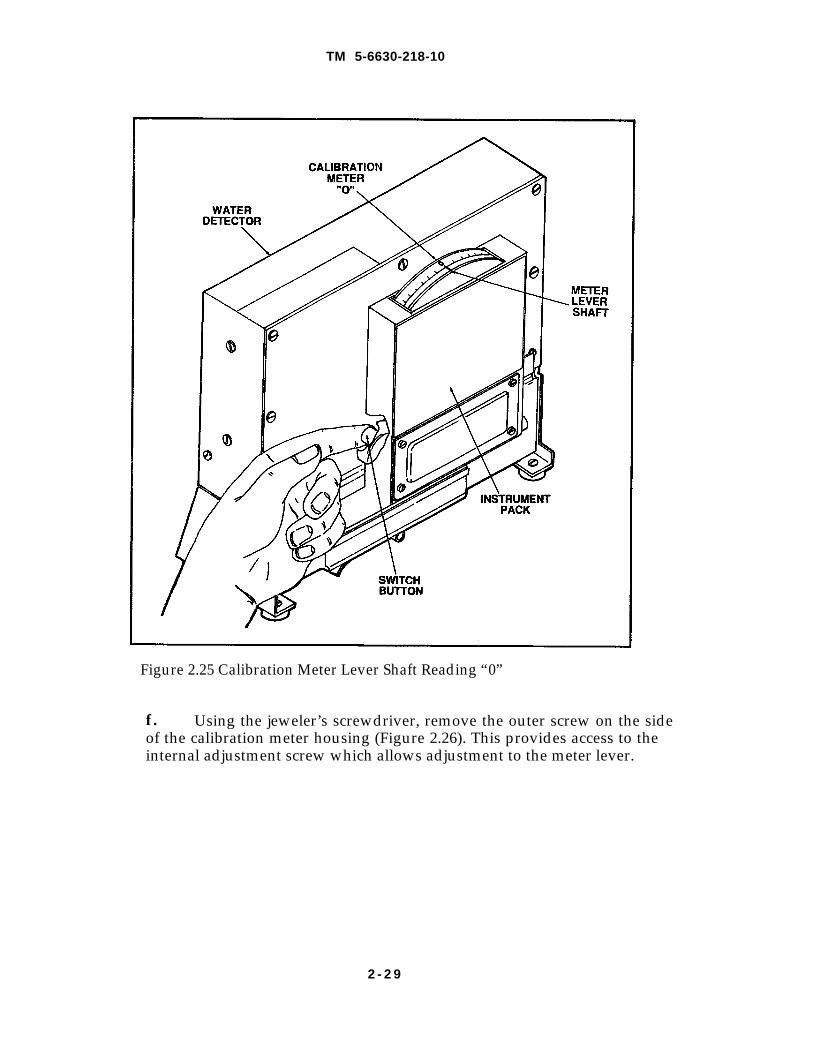
e. Depress the switch button on the instrument pack and read thecalibration meter: if the meter reads “0”, the water detector calibrationprocedure is complete (Figure 2.25). If the meter reads any incrementother than “0”, you must adjust the internal calibration screw until thewater detector is “zeroed-out” (i.e., the meter lever shaft reads “0”). See f.,g., and h. below for instructions. Also refer to the calibration card storedwith Kit Find No. 34.
2 - 2 8
TM 5-6630-218-10
Figure 2.25 Calibration Meter Lever Shaft Reading “0”
f. Using the jeweler’s screwdriver, remove the outer screw on the sideof the calibration meter housing (Figure 2.26). This provides access to theinternal adjustment screw which allows adjustment to the meter lever.
2 - 2 9
TM 5-6630-218-10
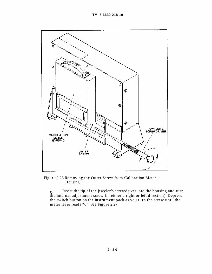
Figure 2.26 Removing the Outer Screw from Calibration MeterHousing
g. Insert the tip of the jeweler’s screwdriver into the housing and turnthe internal adjustment screw (in either a right or left direction). Depressthe switch button on the instrument pack as you turn the screw until themeter lever reads “0”. See Figure 2.27.
2 - 3 0
TM 5-6630-218-10
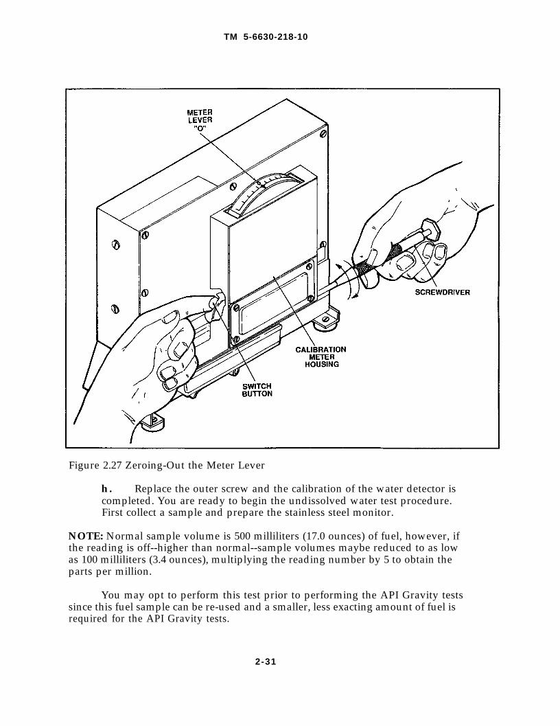
Figure 2.27 Zeroing-Out the Meter Lever
h. Replace the outer screw and the calibration of the water detector iscompleted. You are ready to begin the undissolved water test procedure.First collect a sample and prepare the stainless steel monitor.
NOTE: Normal sample volume is 500 milliliters (17.0 ounces) of fuel, however, ifthe reading is off--higher than normal--sample volumes maybe reduced to as lowas 100 milliliters (3.4 ounces), multiplying the reading number by 5 to obtain theparts per million.
You may opt to perform this test prior to performing the API Gravity testssince this fuel sample can be re-used and a smaller, less exacting amount of fuel isrequired for the API Gravity tests.
2-31
TM 5-6630-218-10
2.5.1.3 Installing the Quick-Release Valve
Follow the procedure for installing the quick-release valve as described inSection 2.3.2. Refer to Figure 2.1.
CAUTIONMake sure that the pressure in the system does not exceed 100 psi. Damage tothe system fuel lines or components might result.
2.5.2 Preparing the Stainless Steel Monitor
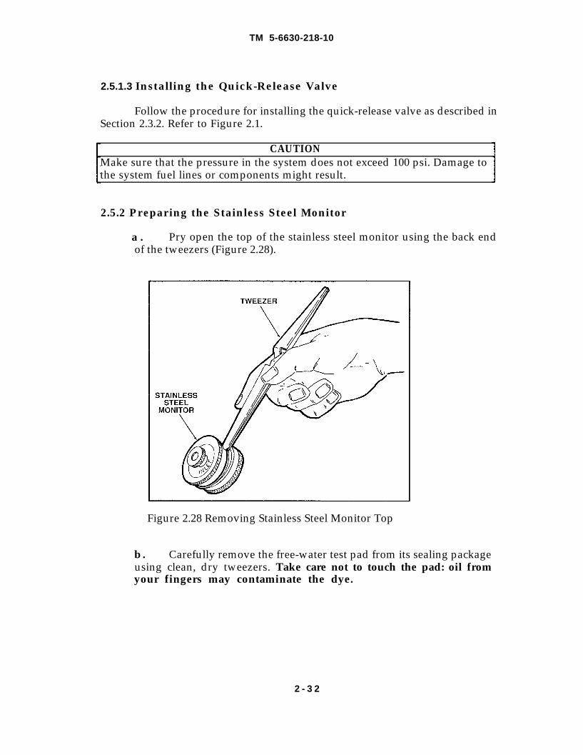
a . Pry open the top of the stainless steel monitor using the back endof the tweezers (Figure 2.28).
Figure 2.28 Removing Stainless Steel Monitor Top
b. Carefully remove the free-water test pad from its sealing packageusing clean, dry tweezers. Take care not to touch the pad: oil fromyour fingers may contaminate the dye.
2 - 3 2
TM 5-6630-218-10
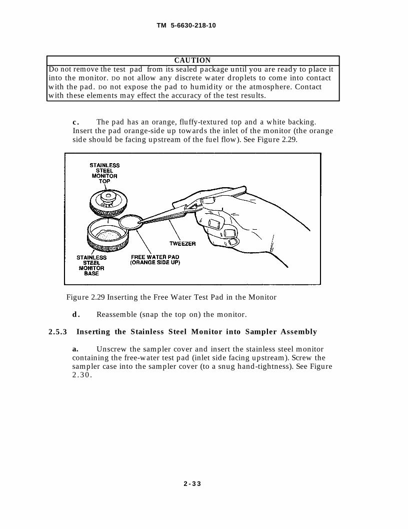
CAUTIONDo not remove the test pad from its sealed package until you are ready to place itinto the monitor. Do not allow any discrete water droplets to come into contactwith the pad. Do not expose the pad to humidity or the atmosphere. Contactwith these elements may effect the accuracy of the test results.
c . The pad has an orange, fluffy-textured top and a white backing.Insert the pad orange-side up towards the inlet of the monitor (the orangeside should be facing upstream of the fuel flow). See Figure 2.29.
Figure 2.29 Inserting the Free Water Test Pad in the Monitor
2.5.3
d. Reassemble (snap the top on) the monitor.
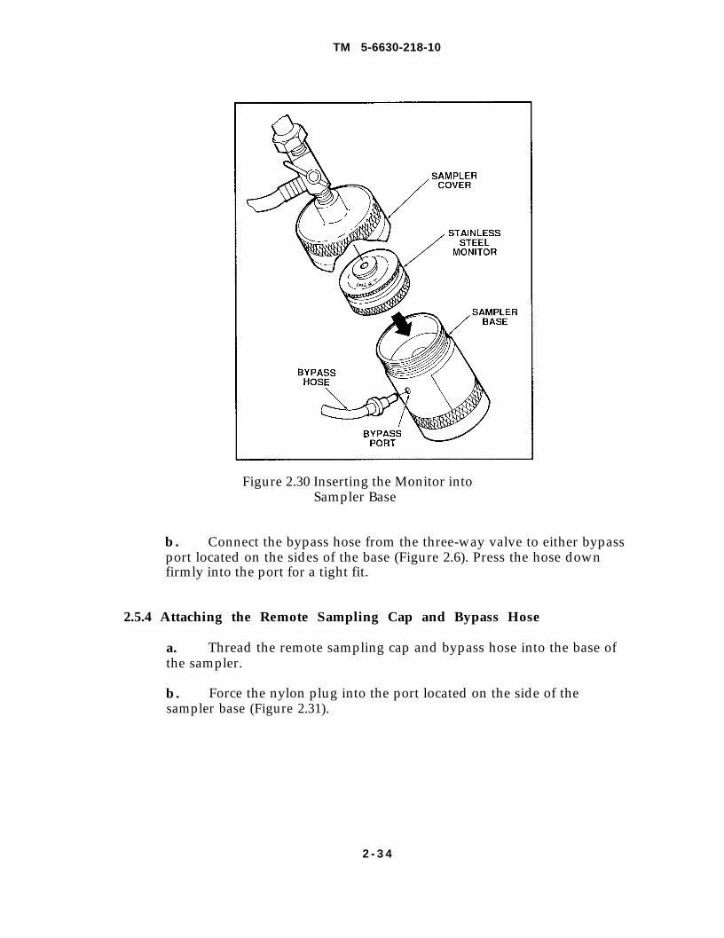
Inserting the Stainless Steel Monitor into Sampler Assembly
a. Unscrew the sampler cover and insert the stainless steel monitorcontaining the free-water test pad (inlet side facing upstream). Screw thesampler case into the sampler cover (to a snug hand-tightness). See Figure2 . 3 0 .
2 - 3 3
TM 5-6630-218-10
Figure 2.30 Inserting the Monitor intoSampler Base
b. Connect the bypass hose from the three-way valve to either bypassport located on the sides of the base (Figure 2.6). Press the hose downfirmly into the port for a tight fit.
2.5.4 Attaching the Remote Sampling Cap and Bypass Hose
a. Thread the remote sampling cap and bypass hose into the base ofthe sampler.
b. Force the nylon plug into the port located on the side of thesampler base (Figure 2.31).
2 - 3 4
TM 5-6630-218-10
2.5.5
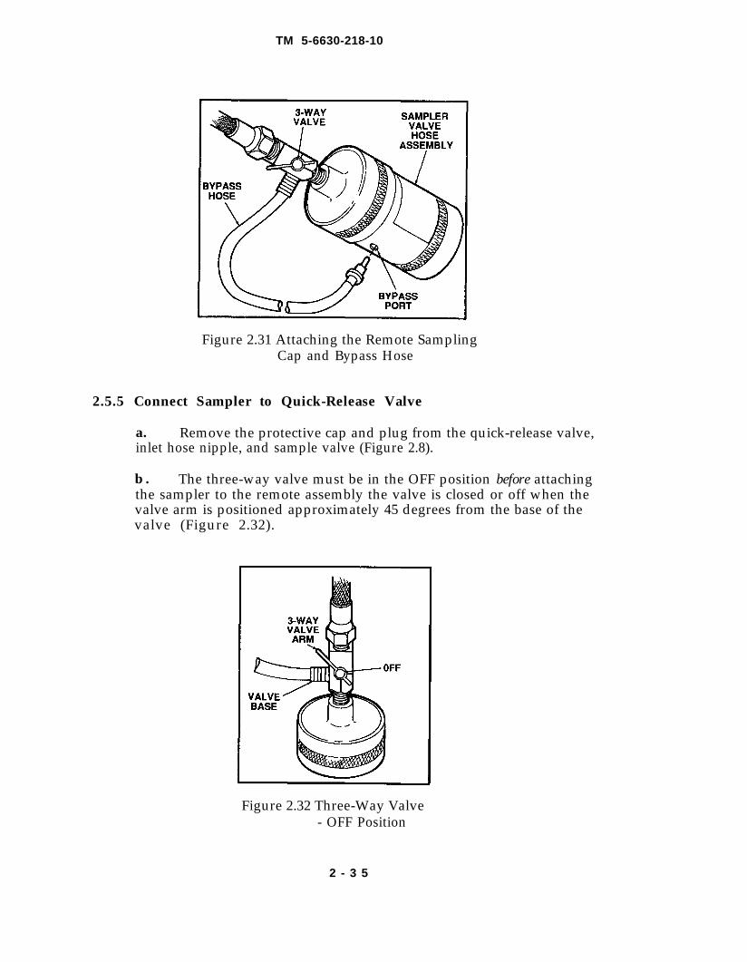
Figure 2.31 Attaching the Remote SamplingCap and Bypass Hose
Connect Sampler to Quick-Release Valve
a. Remove the protective cap and plug from the quick-release valve,inlet hose nipple, and sample valve (Figure 2.8).
b . The three-way valve must be in the OFF position before attachingthe sampler to the remote assembly the valve is closed or off when thevalve arm is positioned approximately 45 degrees from the base of thevalve (Figure 2.32).
Figure 2.32 Three-Way Valve- OFF Position
2 - 3 5
TM 5-6630-218-10
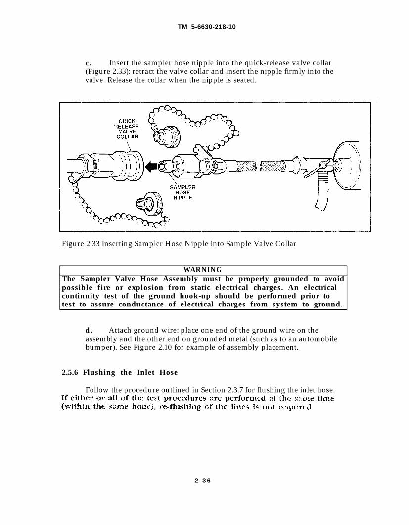
c. Insert the sampler hose nipple into the quick-release valve collar(Figure 2.33): retract the valve collar and insert the nipple firmly into thevalve. Release the collar when the nipple is seated.
Figure 2.33 Inserting Sampler Hose Nipple into Sample Valve Collar
WARNINGThe Sampler Valve Hose Assembly must be properly grounded to avoidpossible fire or explosion from static electrical charges. An electricalcontinuity test of the ground hook-up should be performed prior totest to assure conductance of electrical charges from system to ground.
d. Attach ground wire: place one end of the ground wire on theassembly and the other end on grounded metal (such as to an automobilebumper). See Figure 2.10 for example of assembly placement.
2.5.6 Flushing the Inlet Hose
Follow the procedure outlined in Section 2.3.7 for flushing the inlet hose.
2 - 3 6
TM 5-6630-218-10
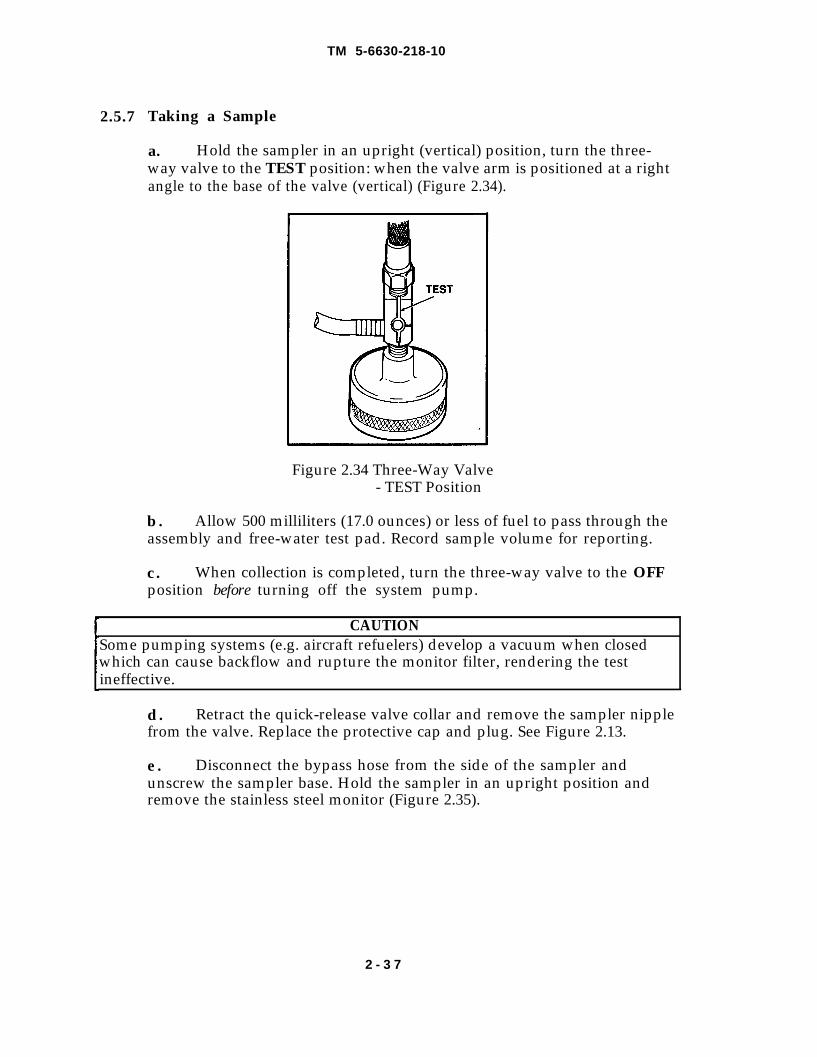
2.5.7 Taking a Sample
a. Hold the sampler in an upright (vertical) position, turn the three-way valve to the TEST position: when the valve arm is positioned at a rightangle to the base of the valve (vertical) (Figure 2.34).
Figure 2.34 Three-Way Valve- TEST Position
b. Allow 500 milliliters (17.0 ounces) or less of fuel to pass through theassembly and free-water test pad. Record sample volume for reporting.
c . When collection is completed, turn the three-way valve to the OFFposition before turning off the system pump.
CAUTIONSome pumping systems (e.g. aircraft refuelers) develop a vacuum when closedwhich can cause backflow and rupture the monitor filter, rendering the testineffective.
d. Retract the quick-release valve collar and remove the sampler nipplefrom the valve. Replace the protective cap and plug. See Figure 2.13.
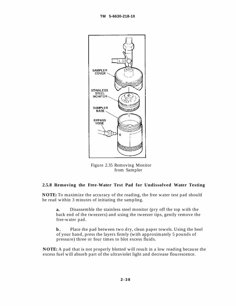
e . Disconnect the bypass hose from the side of the sampler andunscrew the sampler base. Hold the sampler in an upright position andremove the stainless steel monitor (Figure 2.35).
2 - 3 7
TM 5-6630-218-10
Figure 2.35 Removing Monitorfrom Sampler
2.5.8 Removing the Free-Water Test Pad for Undissolved Water Testing
NOTE: To maximize the accuracy of the reading, the free water test pad shouldbe read within 3 minutes of initiating the sampling.
a. Disassemble the stainless steel monitor (pry off the top with theback end of the tweezers) and using the tweezer tips, gently remove thefree-water pad.
b. Place the pad between two dry, clean paper towels. Using the heelof your hand, press the layers firmly (with approximately 5 pounds ofpressure) three or four times to blot excess fluids.
NOTE: A pad that is not properly blotted will result in a low reading because theexcess fuel will absorb part of the ultraviolet light and decrease flourescence.
2 - 3 8
TM 5-6630-218-10
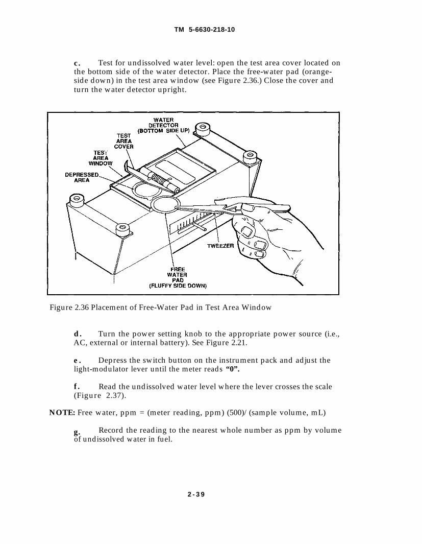
c . Test for undissolved water level: open the test area cover located onthe bottom side of the water detector. Place the free-water pad (orange-side down) in the test area window (see Figure 2.36.) Close the cover andturn the water detector upright.
Figure 2.36 Placement of Free-Water Pad in Test Area Window
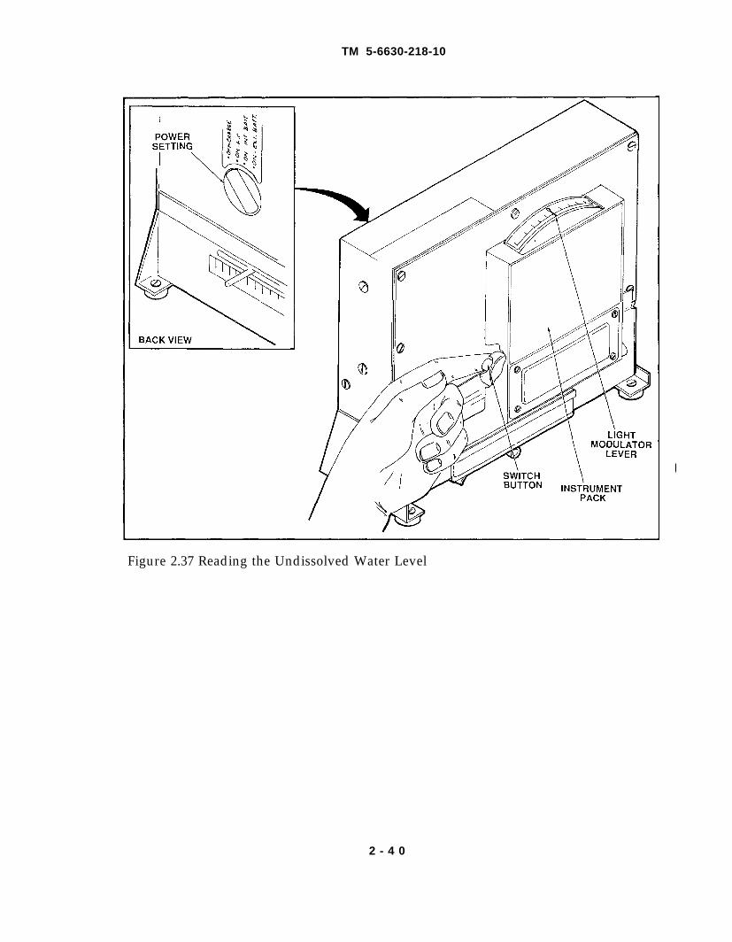
d. Turn the power setting knob to the appropriate power source (i.e.,AC, external or internal battery). See Figure 2.21.
e . Depress the switch button on the instrument pack and adjust thelight-modulator lever until the meter reads “0”.
f. Read the undissolved water level where the lever crosses the scale(Figure 2.37).
NOTE: Free water, ppm = (meter reading, ppm) (500)/(sample volume, mL)
g. Record the reading to the nearest whole number as ppm by volumeof undissolved water in fuel.
2 - 3 9
TM 5-6630-218-10
Figure 2.37 Reading the Undissolved Water Level
2 - 4 0
TM 5-6630-218-10
Chapter 3. Cleaning and Maintenance
3.1 Introduction
With proper care and maintenance, the materials used to construct theAviation Fuel Contaminant Test Kit are designed for trouble-free performancethroughout a long product lifetime. The following basic procedures for cleaningand care, if rigidly observed, can eliminate problems resulting from impropercare. For specific replacement parts, refer to the equipment list on pages 1-2through 1-4 and the corresponding Loading Plan (Figure 1.1) on page 1-5.
3.2 Kit Maintenance
Perform the following five steps according to a maintenance scheduledeveloped for specific site requirements.
3.2.1 Completely disassemble all fuel line parts and components (includingtubing and connectors) that come in contact with fuel.
When unscrewing or replacing threaded fittings, take particular care not todamage the metal threads which may weaken the line and cause leakage, As ageneral rule, threaded fittings located upstream of the filters can be left in place,except when dealing with liquids that deposit heavy residues. You maysupplement fuel line seals with Teflon tape which should be periodically removedand replaced.
3.2.2 Remove all O-rings and gaskets from their seats, If necessary, use flat-bladeunserrated forceps to pry O-rings out of their grooves.
3.2.3 Inspect all O-rings and gaskets for embedded dirt and remove any dirt witha gentle scraping. If grit particles are deeply embedded, replace the O-ring orgasket rather than excavate the grit and risk damaging a seal.
3.2.4 Carefully examine O-rings and gaskets for cracks and deep or largeabrasions: discard and replace the part if the integrity of the part is compromised.For a list of replacement parts, see the equipment list on pages 1-2 through 1-4and Figure 1.1, Page 1-5, Loading Plan.
3.3 Kit Cleaning
Perform the following five steps according to site specified standards after eachtesting session:
3-1
TM 5-6630-218-10
W A R N I N GBe sure all parts/components are clean and dry of fuel before airflight:an explosion or ignition might result from residual solvents.
3.3.1 Flush all parts/components with hot, flowing tap water to remove loosedirt particles. Wash each piece separately with a hot water and non-abrasive soapsolution. Rub or gently scrub the various surfaces as described in the followingsteps until any dirt or dirt film is thoroughly cleaned from the piece.
3.3.2 Vigorously scrub smooth metal surfaces (DO NOT scrub filter supportscreens) with a sponge or soft bristle brush. Be systematic to ensure cleaning ofentire surface area.
3.3.3 On threaded parts, use a stiff bristle brush to remove matter sticking to thebottoms of the threads.
3.3.4 O-ring grooves are best cleaned by using a cotton-tip swab, rubbingsystematically along the entire length of the groove.
3.3.5 wash all O-rings and gaskets in the same soapy solution being careful not toscratch their surfaces. If adherent material strongly resists removal, replace thepart rather than damaging the piece from scrubbing too hard.
CAUTIONAs a general rule, do not use special solvents to remove stains or stubborn soil. Ifproper cleaning is performed routinely (after each use) stains and soil will beminimized. Remember that the harmful effects of overzealous cleaningtechniques can far outweigh the effect of the stain on the function of the part orcomponent.
3.3.6 After cleaning, thoroughly rinse all components in hot, flowing water thenrinse again with cold water. It is always good practice -- and essential in criticalapplications -- to prefilter the final rinse water for removal of any entrained dirt.In hard-water areas, distilled or de-ionized water might be needed for the finalrinse to remove any deposits.
3.3.7 After the final rinse, re-inspect O-rings and gaskets for cracks or otherdamage. Replace them if damaged.
3-2
TM 5-6630-218-10
3.4 Drying and Storage
Dry all components completely before storing with a clean, soft absorbentcloth and if available, a blast of compressed air. If compressed air is used it mustbe entirely free of oil droplets and dirt particles. When thoroughly dried, re-assemble the equipment and store it in its appropriate slot in the kit’s foaminsert. (see Figure 1.1, Loading Plan, page 1-5.)
3.5 Hydrometer Maintenance and Cleaning
The hydrometers come in direct contact with fuel and should be properlycleaned and wiped dry before storing and re-use. Follow these three steps aftereach use:
3.5.1 Wipe excess fuel off the glass hydrometer(s) with clean, soft absorbentcloth.
3.5.2. Wipe the glass hydrometer(s) with a second cloth that has beendampened with the specified cleaning solvent for the type of fuel tested and allowsolvent to air dry (excess may be wiped with a dry cloth).
3.5.3 when completely dry, place the hydrometer(s) inside the protectivecontainer.
3-3

TM 5-6630-218-10
By Order of the Secretary of the Army:
Official:
WILLIAM J. MEEHAN, IIBrigadier General, United States Army
The Adjutant General
CARL E. VUONOGeneral, United States Army
Chief of Staff
DISTRIBUTION:To be distributed In accordance with DA Form 12-25A, Operator Maintenance Requirements forWater Quality Analysis Sets, Prev Med/Engineer.

PIN: 040564-000
This fine document...
Was brought to you by me:
Liberated Manuals -- free army and government manuals
Why do I do it? I am tired of sleazy CD-ROM sellers, who take publicly available information, slap “watermarks” and other junk on it, and sell it. Those masters of search engine manipulation make sure that their sites that sell free information, come up first in search engines. They did not create it... They did not even scan it... Why should they get your money? Why are not letting you give those free manuals to your friends?
I am setting this document FREE. This document was made by the US Government and is NOT protected by Copyright. Feel free to share, republish, sell and so on.
I am not asking you for donations, fees or handouts. If you can, please provide a link to liberatedmanuals.com, so that free manuals come up first in search engines:
<A HREF=http://www.liberatedmanuals.com/>Free Military and Government Manuals</A>
– SincerelyIgor Chudovhttp://igor.chudov.com/
– Chicago Machinery Movers