avid unity isis switch reference guideresources.avid.com/supportfiles/attach/isis_switch_ref... ·...
TRANSCRIPT

ISIS Qualified Switch Reference Guide v2.0.2
Avid ISIS Qualified Ethernet Switches Reference Guide
Revision Date Comments
0.1 3-21-2006 First draft sent for review
0.2 3-24-2006 Added feedback from 1st review
0.3 4-1-2006 Added IP Helper Proc by Vendor
0.4 4-4-2006 More feedback from 1st review
0.5 4-5-2006 Added feedback from 2nd review
1.0 4-10-2006 Added support for Zone 3 test ports on Configs A, B and E
1.1 8-3-2006 Minor corrections to loading Cisco configuration and updated switch firmware table
1.2 6-11-2007 Add IOS procedure and update firmware/IOS revisions supported
1.3 1-30-2008 Many updates including: Updated Table 1, added section APN Switch Redundancy, Table 2, and Table 12
2.0 11-7-2008 Added Cisco 4900M, updated IOS versions, corrected some procedure steps, added disabling ip routing to Cisco, added A & E configurations for Cisco 4900M, added link aggregation information for Cisco 6509
2.0.2 3-19-2009 Removed changing IP address for corporate uplink for SMC 8724; Added instructions for manually setting queue depth on Foundry
V 2.0.2 Page 1 5/6/2009

ISIS Qualified Switch Reference Guide v2.0.2
Contents
Introduction ..................................................................................................................................... 4
Avid ISIS Default Configuration for Avid Production Network Switch ............................................ 6
Access for Configuring Switches .................................................................................................. 7
Accessing the Switch Through Telnet ...................................................................................... 7
Accessing the Switch Through HyperTerminal ........................................................................ 7
TFTP ............................................................................................................................................. 8
Default Passwords ....................................................................................................................... 8
APN Switch Redundancy ............................................................................................................. 8
Foundry X424 2XG ........................................................................................................................... 9
Loading the Avid Default Configuration ...................................................................................... 9
Upgrading Firmware ...................................................................................................................... 10
Changing the IP Address associated with a VLAN ..................................................................... 11
Changing the IP Address associated with the Corporate Uplink ............................................... 11
Configuring Buffer Pool to Support Editing Clients ................................................................... 12
Changing Buffer Pool on Uplink Ports ....................................................................................... 12
Removing/Adding Ports Associated to a VLAN ......................................................................... 13
Enabling or Disabling IP Routing ................................................................................................ 13
Creating Trunked Ports (Link Aggregation) ............................................................................... 14
Setting up IP-Helper Addresses for DHCP ................................................................................. 14
Cisco 4900M and 4948 .................................................................................................................. 15
Loading the Avid Default Configuration .................................................................................... 15
Upgrading IOS ............................................................................................................................ 15
Changing the IP Address Associated with a VLAN ..................................................................... 17
Changing the IP Address associated with the Corporate Uplink ............................................... 17
Adding ports associated to a VLAN ........................................................................................... 17
Enabling or Disabling IP Routing ................................................................................................ 18
Creating an EtherChannel (link aggregation) ............................................................................ 19
Setting Up IP-Helper Addresses for DHCP ................................................................................. 21
SMC 8724 ML3 ............................................................................................................................... 21
Loading a Configuration ............................................................................................................ 21
Upgrading Firmware and Boot Code ......................................................................................... 22
Changing the IP Address Associated with a VLAN ..................................................................... 22
Removing/Adding Ports Associated to a VLAN ......................................................................... 23
V 2.0.2 Page 2 5/6/2009
ISIS Qualified Switch Reference Guide v2.0.2
Enabling or Disabling IP Routing ................................................................................................ 23
Setting up IP-Helper Addresses for DHCP ................................................................................. 23
Appendix ........................................................................................................................................ 24
Sample Configurations and Associated Files by Switch Vendor ................................................ 24
Configuration A: Single L3 APN Switch Supports Zones 1, Zone 2, and limited Zone 3 ....... 24
Configuration B: Single L3 APN Switch for Support of Zone 1, Zone 2, and Zone 3 Support via GigE link aggregation.......................................................................................... 27
Configuration C: Single L2 APN Switch dual 10 Gb Connections Supports Zone 1 and Zone 2 only. No IP Routing .................................................................................................. 28
Configuration D: Single L2 APN Switch single 10 Gb Connections Support Zones1 and Zone 2 only, no IP Routing ..................................................................................................... 29
Configuration E: L3 Switches with Router Redundancy ....................................................... 30
Switch Vendor Commands ........................................................................................................ 33
V 2.0.2 Page 3 5/6/2009

ISIS Qualified Switch Reference Guide v2.0.2
Introduction
The purpose of this document is to provide ISIS Administrators with a single reference regarding the implementation, configuration and troubleshooting of all Avid ISIS qualified Ethernet switches for use as the Avid Production Network Switch (APN). The switches covered in this documented are listed in the following two tables. These switches have been fully qualified by Avid in the configurations presented in this document. However, in order to reduce the complexity of this document, configurations are limited to the switches that are listed in Table 1. While most of this information can be applied to the switches in Table 2, Avid recommends you refer to the vendor’s documentation for specifics.
Table 1 Supported APN Switches offered by Avid
Manufacturer Model Firmware/IOS Description
Cisco 4900M Rommon:
12.2(44r)SG
IOS: 12.2(46)SG Minimum requirement
40 GigE (RJ-45) WS-X4920-GB-RJ45
or
8 10 Gb (X2/SC) WS-X4904-10GE 8 10 Gb (X2/SC)
Cisco 4948 10GE Rommon:
12.2(31r)SGA minimum requirement
IOS: 12.2 (25)
EWA8 minimum requirement
48 GigE (RJ-45), 2-10 Gb (X2/SC)
Foundry FESX424 Firmware Version 02.3.01T3e3
BootROM Version 02.3.01Te6 minimum requirement
24 GigE (RJ-45), 4 GigE (SFP), 2-10 Gb (XFP/LC)
SMC 8724ML3 Loader Version: 3.1.0.0
Boot ROM Version: 3.1.0.0
Operation Code Version: 3.1.1.56 minimum requirement
24 GigE (RJ-45)
4 GigE (SFP)
V 2.0.2 Page 4 5/6/2009

ISIS Qualified Switch Reference Guide v2.0.2
Table 2 Supported APN Switches not offered by Avid
Cisco Foundry
Model Approved Blades Model Approved Blades
4500 Supervisor: WS-X4516-10GE FESX 4482 N/A
WS-X4306-GB
WS-X4506-GB-T SuperX2 fi-sx4-12-combo-port-management-module
fi-sx4-24-port-gig-copper-module
6500 Supervisor: WS-SUP720/WS-F6K-PFC3B fi-sx4-24-port-gig-fiber-module
WS-X6704-10GE/ WS-F6700-CFC fi-sx4-2-port-10g-module
WS-X6748-GE-TX/WS-F6700-CFC/DFC1
WS-X6748-SFP/WS-F6700-CFC/DFC1 RX RX-BI-MR Management Module
WS-X6708-10GE/WS-F6700-DFC3CXL RX-BI-SFM3 Fabric Module
RX-BI-24C
1. Due to limited buffering this blade does not support uplinks to additional switches. It only supports direct connected clients. RX-BI24F
RX-BI-4XG
2. Requires Queue Depth changes outlined in Qualified Switch Guide
V 2.0.2 Page 5 5/6/2009

ISIS Qualified Switch Reference Guide v2.0.2
Avid ISIS Default Configuration for Avid Production Network Switch
Each vendor’s switch, when purchased from Avid, comes configured with an Avid Default configuration outlined in Configuration A. If the default configuration is not compatible with your system use one of the configurations provided to create a compatible file. The configuration has to be applied using the same procedure outlined later, by vendor, in this document. The Avid Default Configuration has a provision for one port to connect to the House Network for Zone 3 support. That port is 24 for Foundry and SMC, and 48 for Cisco. The following table shows the default port allocations by zone.
Table 3 Switch Matrix
Model RU GigE Ports 10 Gb Ports Mgmt. Ports Comments
Cisco 4900M 2 40 RJ-45 8 X2 (SC) 2 RJ-45 (One Serial, One Ethernet)
Avid Supports both SR (850 nm) and LR (1310 nm) X2s in 10 Gb ports.
Ethernet Mgmt. Port used in Rommon mode only.
Cisco 4948 1 48 RJ-45 2 X2 (SC) 2 RJ-45 (One Serial, One Ethernet)
Avid Supports both SR (850 nm) and LR (1310 nm) X2s in 10 Gb ports.
Ethernet Mgmt. Port used in Rommon mode only.
Foundry X424 2XG
2 24 RJ-45 4 SFP
2 XFP (LC) 1 DB-9 serial Avid Supports both SR (850 nm) and LR (1310 nm) XFPs in 10 Gb ports.
Optical GigE SFP Ports 1F – 4F can be used in place of RJ-45 Ports 1 – 4.
SMC 8724ML3
1 24 RJ-45 4 SFP
None Supported 1 DB-9 serial Optical GigE SFP Ports 21 – 24 can be used in place of RJ-45 Ports 21 – 24.
V 2.0.2 Page 6 5/6/2009

ISIS Qualified Switch Reference Guide v2.0.2
Table 4 Avid Factory Default port allocations
Model VLAN 10 VLAN 20 VLAN 30 VLAN 40
Zone 3 Test Port
House Network
Uplink
Cisco 4900M Ports 2/1-2/20, 1/1-1/4
Ports 3/1-3/16, 1/5-1/7
Ports 3/17-19 3/20 Port 1/8
Cisco 4948 Ports 1-24 Ports 25-46 47 Port 48
Foundry X424 Ports 1-12 Ports 13-22 23 Port 24
SMC 8724ML3
Ports 1-12 Ports 13-23 N/A Port 24
Access for Configuring Switches
There are two methods for accessing the switches. The following sections describe the two processes.
Accessing the Switch Through Telnet
You can access the switch console using remote systems on the network. Telnet is a common way to remotely access the switch using a network client system. You need to know the IP address of the target switch channel.
To access your Switch using Telnet:
1. Make sure your switch is powered on.
2. Connect the Ethernet port on your switch to your network.
3. From a network client system, click Start > Run.
4. Type Telnet <switch IP> and press Enter.
Accessing the Switch Through HyperTerminal
Each vendor’s switch provided by Avid is accompanied with the proper serial cable. You can access the switch configuration settings using HyperTerminal through the serial connection. You need to set the following serial protocol:
• Baud Rate — 9600
• Data Bits — 8
• Parity — None
• Stop Bits — 1
• Flow Control — None
V 2.0.2 Page 7 5/6/2009

ISIS Qualified Switch Reference Guide v2.0.2
To access your switch using HyperTerminal:
1. Make sure your switch is powered on.
2. Connect the serial COM port on your computer to the serial connector on the switch. The correct serial cable is supplied with each vendor’s switch. For Cisco 4948, the top RJ-45 port (next to 10 Gb port 49) marked “Con” is the serial connection.
3. From a Windows system, click Start > Programs > Accessories > Communications > HyperTerminal.
4. Type a name for the connection, select the COM port, and configure the connection using the serial protocol previously listed.
TFTP
In order to copy firmware and configuration files from the Host to the switch you need a TFTP application. You can find several on the Internet. The most common application used at Avid is called TFTPD32.exe. You can download a copy of this program at the following URL: http://tftpd32.jounin.net/.
When configuring the TFTP application makes sure that the IP of the Server Interface is on the same subnet as the switch with which you are attempting to communicate. Also, make sure that the files you are trying to transfer are in the directory designated as the root for the TFTP application. This is sometimes referred to as the Base Directory.
Default Passwords
It should also be noted that the following default passwords exist in order for one to access enable mode on the switches. The following table lists the passwords for each vendor.
Table 5 Default Enable Passwords
Manufacturer Model Password Comments
Cisco 4900M & 4948 Not Set by Default In order to get into enable mode via a Telnet session you must create an enable password via the serial connection. This can be done in Global Configure Mode by using the “Enable Secret” command.
Foundry X424 Not Set by Default Press enter to access enable mode.
SMC 8724ML3 User: admin Password: admin
APN Switch Redundancy
In the Appendix of this document you will find Configuration E, which outlines the redundant APN switch configuration. This is a highly recommended and common configuration in an ISIS
V 2.0.2 Page 8 5/6/2009

ISIS Qualified Switch Reference Guide v2.0.2
environment. In this configuration VRRP, VRRP-E, HSRP or GLBP is used between the redundant ISIS VLANs, while a routing protocol like RIP or OSPF is used on the uplink to the “House” network. For specific configuration examples by protocol seeTable 12, Redundant Switch Configuration Examples by ISIS VLAN.
For the Foundry based configurations, Avid has only tested VRRP-E. For the Cisco based configurations HSRP and GLBP have been tested. For Cisco, Avid has found GLBP to be the best performer. However, GLBP is not offered in all switch models and HSRP may be the only option.
Avid has only tested OSPF between the APN and House Uplink. It was found to provide the fastest repair time when failures were introduced into the network. Recovery times may vary depending on the type and size of your network.
Foundry X424 2XG
Loading the Avid Default Configuration
Refer to the Access for Configuring Switches and TFTP sections for setup information related to this procedure.
This procedure assumes that you are using the Avid default IP for VLAN 10 (Ports 1 – 12 for Foundry or SMC, or 1 – 24 for Cisco) on the switch with an Interface IP of 192.168.10.2. If not, change the IPs written in the procedure to match your IP scheme. If you received a Foundry switch that has not been configured with the Avid file then it is likely that the IP address for VLAN 1 is 209.157.22.154.
1. Connect the Host PC to VLAN 10 of the switch (See Table 2).
2. Establish a connection to the switch’s CLI (See Access for Configuring Switches).
3. Launch the TFTP application. Make sure you choose the proper NIC for the Server Interface and that the file you are uploading is in the Base Directory.
4. SwitchHostName >en
5. SwitchHostName #: copy tftp startup-config [tftp server IP] [config file name]
6. Click on the TFTP window that you placed into the background, and check to see if any errors occurred during the copy.
7. SwitchHostName#reload
8. Choose “y” to confirm the reload.
9. Choose “y” to reload without saving changes to the running configuration. If you choose “no” you will overwrite the startup configuration you just loaded.
If you connected to the CLI via telnet you may have to change the IP of your Host’s interface to re-establish a telnet connection to the switch.
V 2.0.2 Page 9 5/6/2009

ISIS Qualified Switch Reference Guide v2.0.2
Upgrading Firmware
This upgrade should only apply to a small number of switches that were shipped to customers prior to the official 1.0 release of ISIS. However, it is included in this document for reference because much of the procedure applies to normal upgrade process. The unique part about this upgrade procedure is that because it involves moving up three revisions, from 2.0 to 2.3, the procedure requires an interim 2.2 upgrade.
This procedure explains how to load Firmware and Boot ROM for the Foundry X424 (X424) switch. Because this update involves moving from the 2.0 to the 2.3 code an interim 2.2 update is necessary. This procedure assumes that you are using the Avid default IP for VLAN 10 (Ports 1 – 12) on the switch of 192.168.10.2. If not, change the IPs written in the procedure to match your IP scheme. If you received a switch that has not been configured with the Avid file then it is likely that the IP address for VLAN 1 is 209.157.22.154.
If you are using the System Director (not a laptop) to perform the operation, be aware that you need to write down the original NIC card address. You will need to change it back after you complete the loading of the configuration file.
Pre-requisites for loading the Firmware and Boot ROM
• TFTP loaded on the system you are using (can get from net)
• Copy of the Firmware and Boot ROM files for both the 2.2 and 2.3 releases to the root of the C drive (or to the path at which your TFTP program is defaulting). Those files are the following:
o SXZ04000.bin (boot code)
o SXR04100b.bin (flash code)
To load the Firmware and Boot ROM from a system:
1. SwitchHostName#copy tftp fl 192.168.10.1 SXZ04000.bin bootrom
See flash memory write, when finished will say Flash Done.
2. SwitchHostName#copy tftp fl 192.168.10.1 SXR04100b.bin pri
3. SwitchHostName#copy tftp fl 192.168.10.1 SXR04100b.bin sec
4. SwitchHostName#b s f p (this will cause you to lose connection with the telnet session. Wait 1 minute for the switch to reboot).
5. Type: telnet 192.168.10.2
6. SwitchHostName#en
7. SwitchHostName#en, press Enter.
8. SwitchHostName#show flash
V 2.0.2 Page 10 5/6/2009

ISIS Qualified Switch Reference Guide v2.0.2
You should now see the following:
Compressed Pri Code size = 3932846, Version 04.1.00bT3e3 (SXR04100b.bin) Compressed Sec Code size = 3932846, Version 04.1.00bT3e3 (SXR04100b.bin) Compressed BootROM Code size = 524288, Version 04.0.00T3e5 !
If you used the System Director (not a laptop) to perform the above operation, you need to change the address of the NIC board (or onboard NIC) address back to the proper address.
Changing the IP Address associated with a VLAN
1. SwitchHostName>en
2. SwitchHostName#conf t
3. SwitchHostName#(config)#int ve ww (where ww equals 10 for the router-interface on VLAN 10, or 20 for the router-interface on VLAN 20)
4. SwitchHostName(config-vif-10)#no ip address 192.168.Xx.2 255.255.255.0 (Where XX is 10 or 20)
5. SwitchHostName(config-vif-10)#ip address xxx.xxx.xxx.xxx yyy.yyy.yyy.yyy (Where XX is 10 or 20) (where x's equals ip address and y's equals subnet mask)
6. SwitchHostName(config-vif-10)#exit
7. SwitchHostName#(config)#exit
8. SwitchHostName#write mem
9. SwitchHostName#exit
Changing the IP Address associated with the Corporate Uplink
1. SwitchHostName>en
2. SwitchHostName#conf t
3. SwitchHostName(config)#int ethe 24
4. SwitchHostName(config-if-e1000-24)#no ip address 10.10.10.10 255.255.255.0
5. SwitchHostName(config-if-e1000-24)#ip address xxx.xxx.xxx.xxx yyy.yyy.yyy.yyy
6. (where x's equals ip address and y's equals subnet mask)
7. SwitchHostName(config-if-e1000-24)#exit
8. SwitchHostName(config)#exit
9. SwitchHostName#write mem
10. SwitchHostName#exit
V 2.0.2 Page 11 5/6/2009

ISIS Qualified Switch Reference Guide v2.0.2
Configuring Buffer Pool to Support Editing Clients
With the Foundry switch only, you must make changes to the buffers on the ports that will connect to editing clients. For example, if an editing client is connected to port 1 then you would configure the port as follows:
1. SwitchHostName>en
2. SwitchHostName#conf t
3. SwitchHostName(config)#qd 1 896
4. SwitchHostName(config)#qd 1 896 7
5. SwitchHostName(config)#exit
6. SwitchHostName#wr mem
7. SwitchHostName#exit
Changing Buffer Pool on Uplink Ports
With the Foundry switch only, if you need to connect the switch to the House Network then you must make changes to the buffers on the ports that will connect to the House Network. For example by default port 24 is designated to connect to the House Network. However, the default buffers are not set up to support Video/Audio playback through that link. The following procedure explains how to make that change.
1. SwitchHostName>en
2. SwitchHostName#conf t
3. SwitchHostName(config)#qd 24 4095
4. SwitchHostName(config)#qd 24 4095 7
5. SwitchHostName(config)#exit
6. SwitchHostName#wr mem
7. SwitchHostName#exit
V 2.0.2 Page 12 5/6/2009

ISIS Qualified Switch Reference Guide v2.0.2
Removing/Adding Ports Associated to a VLAN
In the Foundry switch you must remove a port from a given VLAN before you can add it to another. The following procedure shows how to do both:
1. SwitchHostName>en
2. SwitchHostName#conf t
3. SwitchHostName(config)#vlan x (where x is the VLAN #)
4. SwitchHostName(config-vlan-x)#no untagged ethernet x to y
5. SwitchHostName(config-vlan-x)#vlan y (where y is the other VLAN #)
6. SwitchHostName(config-vlan-y)#untagged ethernet x to y
7. SwitchHostName(config-vlan-y)#exit
8. SwitchHostName(config)#exit
9. SwitchHostName#wr mem
10. SwitchHostName#exit
Enabling or Disabling IP Routing
Unlike the Cisco or SMC switches, there is no “ip routing” command in the Foundry switch. If you do not want the switch to perform Layer 3 operations (i.e., routing between subnets) then you must remove IP addresses associated to all but one router interface. Once there is more than one subnet defined in the switch configuration the switch will route between them.
Use the procedure outlined in section C to remove the IP address associated to a router interface. You may also choose to disable a router interface. To do so do the following:
1. SwitchHostName>en
2. SwitchHostName#conf t
3. SwitchHostName(config)#int ve x (where x is the router #)
4. SwitchHostName(config-vif-x)#disable
5. SwitchHostName(config-vif-x)#exit
6. SwitchHostName(config)#exit
7. SwitchHostName#wr mem
8. SwitchHostName#exit
V 2.0.2 Page 13 5/6/2009

ISIS Qualified Switch Reference Guide v2.0.2
Creating Trunked Ports (Link Aggregation)
With the Foundry switch you can trunk (aggregate) up to four ports. The default configuration from Avid that supports trunking includes a trunk of ports 21 to 24. You can create multiple four port trunks.
Keep in mind that depending on to what you are connecting the trunk you may have to change the load balancing algorithm of the switch on the other end. For example, if you are connecting to a Cisco EtherChannel you want to change the load balancing to support source-destination IP address.
1. SwitchHostName>en
2. SwitchHostName#conf t
3. SwitchHostName(config)#trunk ethe x to y
4. SwitchHostName(config)#trunk deploy
5. SwitchHostName(config)#exit
6. SwitchHostName#wr mem
7. SwitchHostName#exit
Setting up IP-Helper Addresses for DHCP
If you want to use DHCP on the clients that are connected to the Avid Production switch you will need to add an IP Helper Address to each VLAN. The IP Helper Address points the hosts to the DHCP Server that is on the house network.
1. SwitchHostName#conf t
2. SwitchHostName(config)#int ve n (where n is the router-interface #)
3. SwitchHostName(config-vif-n)#ip helper-address 1 xxx.xxx.xxx.xxx (where x's equals the ip address of the DHCP Server)
4. SwitchHostName(config-vif-n)#exit
5. SwitchHostName(config)#exit
6. SwitchHostName#wr mem
Repeat this for each VLAN that requires it.
V 2.0.2 Page 14 5/6/2009

ISIS Qualified Switch Reference Guide v2.0.2
Cisco 4900M and 4948
Loading the Avid Default Configuration
Refer to the Access for Configuring Switches and TFTP sections for setup information related to this procedure.
This procedure assumes that you are using the Avid default IP for VLAN 10 on the switch with a Router interface IP of 192.168.10.2. If not, change the IPs written in the procedure to match your IP scheme. In the event that you have received a switch that does not have the Avid Default Configuration loaded, then you will need to apply an IP address to VLAN 1 of the switch so you can transfer the configuration file via TFTP. Follow the steps outlined in Changing the IP Address associated with a VLAN.
1. Connect the Host PC to VLAN 10 of the switch (See Table 2).
2. Establish a connection to the switch’s CLI (See Access for Configuring Switches).
3. Launch the TFTP application. Make sure you choose the proper NIC for the Server Interface and that the file you are uploading is in the Base Directory.
4. SwitchHostName>en (enter password if required)
5. SwitchHostName#: copy tftp startup-config
Address or name of remote host []? Insert IP of TFTP server Source filename []? Insert Config File Name Destination filename [startup-config]? press Enter
6. Click on the TFTP window that you placed into the background, and check to see if any errors occurred during the copy.
7. SwitchHostName#reload
8. Choose “y” to confirm the reload
9. Choose “y” to reload without saving changes to the running configuration. If you choose “no” you will overwrite the startup configuration you just loaded.
If you connected to the CLI via telnet you may have to change the IP of your Host’s interface to re-establish a telnet connection to the switch.
Upgrading IOS
Please note that this procedure differs slightly from that of the one documented by Cisco. Cisco 4948 switches supplied by Avid are configured with a Configuration Register value of 0x2101, which means the switch will boot from the first IOS that appears in bootflash. Cisco instructs you to set the Configuration Register to 0x2102, which means the switch will look for a boot string that points to the IOS from which to boot. In order to remain consistent with what we ship we have chosen to document a procedure based on our current shipping product.
V 2.0.2 Page 15 5/6/2009

ISIS Qualified Switch Reference Guide v2.0.2
1. Use the dir bootflash: command to ensure that there is sufficient space in Flash memory to store the PROM upgrade image. In most cases there will only be one file in bootflash, which leaves plenty of space for the new file. If there is insufficient space, delete one or more images, and then issue the squeeze bootflash: command to reclaim the space.
Example: Switch#delete bootflash:cat4000-i9s-mz.122-25.EWA4.bin Switch#squeeze bootflash:
2. Download the cat4000-ios-promupgrade-122_25r_EWA program into Flash memory using the copy tftp command.
Example: Switch# copy tftp: bootflash: Address or name of remote host [172.20.58.78]? Source filename [cat4000-ipbasek9-mz.122-25.EWA8.bin]? Destination filename [cat4000-ipbasek9-mz.122-25.EWA8.bin]?
3. Use the config-register command to set the configuration register to 0x2101.
Example: Switch# configure terminal Switch(config)# config-register 0x2101 Switch(config)# exit Switch# write Building configuration... Compressed configuration from 3723 to 1312 bytes [OK]
Switch#
4. Archive the previous IOS image in case you need to re-apply at a later time.
Example: Switch#copy bootflash: tftp: Source filename []? cat4000-i9s-mz.122-25.EWA4.bin Address or name of remote host []? 172.20.98.3 Destination filename [cat4000-i9s-mz.122-25.EWA4.bin]?
5. Delete the old IOS image(s), and then issue the squeeze bootflash: command to reclaim the space.
Example: Switch#delete bootflash: cat4000-i9s-mz.122-25.EWA4.bin Switch#squeeze bootflash:
6. Once the squeeze is complete (it will take a few minutes), enter the reload command to reset the switch and load the software.
Example: Switch# reload
Use the show version command to verify that the new Cisco IOS release is operating on the switch.
V 2.0.2 Page 16 5/6/2009

ISIS Qualified Switch Reference Guide v2.0.2
Changing the IP Address Associated with a VLAN
1. SwitchHostName>enable
2. SwitchHostName#conf t
3. SwitchHostName(config)#int vlan ww (where ww equals 10 for VLAN 10, or 20 for VLAN 20)
4. SwitchHostName(config-if)# ip address xxx.xxx.xxx.xxx yyy.yyy.yyy.yyy (where x's equals ip address and y's equals subnet mask)
5. SwitchHostName(config-if)#no shut
6. SwitchHostName(config-if)#exit
7. SwitchHostName(config)#exit
8. SwitchHostName#copy run start
9. SwitchHostName#exit
Changing the IP Address associated with the Corporate Uplink
1. SwitchHostName> en
2. SwitchHostName#conf t
3. SwitchHostName(config)#interface Gi 1/48
4. SwitchHostName(config-if)#no switchport
5. SwitchHostName(config-if)#ip address xxx.xxx.xxx.xxx yyy.yyy.yyy.yyy (where x's equals ip address and y's equals subnet mask)
6. SwitchHostName(config-if)#no shut
7. SwitchHostName(config-if)#end
8. SwitchHostName#copy run start
9. SwitchHostName#exit
Adding ports associated to a VLAN
For Range of Ports
1. SwitchHostName>en
2. SwitchHostName#conf t
3. SwitchHostName(config)# int range gigabitEthernet 1/x-y (where x and y are starting and ending ports)
4. SwitchHostName(config-if-range)#switchport mode access
5. SwitchHostName(config-if-range)#switchport access vlan x (where x is the VLAN to which you want to assign)
V 2.0.2 Page 17 5/6/2009

ISIS Qualified Switch Reference Guide v2.0.2
6. SwitchHostName(config-if-range)#exit
7. SwitchHostName(config)#exit
8. SwitchHostName#copy run start
For Single Port
1. SwitchHostName>en
2. SwitchHostName#conf t
3. SwitchHostName(config)# int gigabitEthernet 1/x (where x is the port number)
4. SwitchHostName(config-if-range)#switchport mode access
5. SwitchHostName(config-if)#switchport access vlan x (where x is the VLAN to which you want to assign)
6. SwitchHostName(config-if-range)#exit
7. SwitchHostName(config)#exit
8. SwitchHostName#copy run start
Enabling or Disabling IP Routing
If the “No IP Routing” command does not show up in the show run output then IP Routing is enabled. This would be located in the upper portion of the show run output. Here is a simple example from a Cisco 4948 where IP Routing is Disabled:
!
version 12.2
no service pad
service timestamps debug uptime
service timestamps log uptime
no service password-encryption
service compress-config
!
hostname Switch
!
boot-start-marker
boot-end-marker
!
V 2.0.2 Page 18 5/6/2009

ISIS Qualified Switch Reference Guide v2.0.2
!
no aaa new-model
vtp mode transparent
ip subnet-zero
no ip routing
Do the following to enable IP routing:
1. SwitchHostName>en
2. SwitchHostName#conf t
3. SwitchHostName(config)#ip routing
4. SwitchHostName(config)#exit
5. SwitchHostName#copy run start
Do the following to disable IP routing:
1. SwitchHostName>en
2. SwitchHostName#conf t
3. SwitchHostName(conf)#no ip routing
4. SwitchHostName(config)#exit
Creating an EtherChannel (link aggregation)
With the Cisco switch you can create EtherChannels (link aggregation) with up to eight ports. The default configuration from Avid that supports and EtherChannel that includes ports 45 to 48. You can create multiple eight port EtherChannels.
Keep in mind that depending on to what you are connecting the EtherChannel you may have to change the load balancing algorithm of the switch on the other end. For example, if you are connecting to a Cisco EtherChannel you want to change the load balancing to support source-destination IP address.
In this example a range of ports is assigned to a VLAN and an Ether Channel (Layer 2) created.
Use the same procedure for creating 10 Gb Etherchannel groups that connect to ISIS.
1. SwitchHostName>en
2. SwitchHostName#conf t
3. SwitchHostName(config)#int port-channel x (where x is the port-channel #)
4. SwitchHostName(config-if)#switchport
5. SwitchHostName(config-if)#switchport mode access
V 2.0.2 Page 19 5/6/2009

ISIS Qualified Switch Reference Guide v2.0.2
6. SwitchHostName(config-if)#switchport access vlan n (where n is the VLAN #)
7. SwitchHostName(config-if)#exit
8. SwitchHostName(config)#int range GigabitEthernet 1/a-b (where a and b are a range of ports)
9. SwitchHostName(config-if-range)#channel-group x mode on (where x is the port-channel #)
10. SwitchHostName(config-if-range)#exit
11. SwitchHostName(config)#port-channel load-balance src-dst-ip
12. SwitchHostName(config)#exit
13. SwitchHostName#copy run start
14. SwitchHostName#exit
The following is information on the Cisco 6509 Etherchannel Configuration for use with 10 Gb ISS link aggregation:
interface Port-channel10
switchport
switchport access vlan 10
switchport mode access
no ip address
interface TenGigabitEthernet1/1
description v10 ISIS echannel
switchport
switchport access vlan 10
switchport mode access
no ip address
channel-group 10 mode on
interface TenGigabitEthernet1/2
description v10 ISIS echannel
switchport
switchport access vlan 10
switchport mode access
no ip address
channel-group 10 mode on
V 2.0.2 Page 20 5/6/2009

ISIS Qualified Switch Reference Guide v2.0.2
Additional information you should know:
• In the previous example, Channel-group 10 was used. You need to make the proper channel group assignment for your site.
• Because the Cisco 6509 defaults to using a “source/destination” IP load balancing algorithm which is required per Avid’s requirements, this should not have to be changed.
The current load-balancing algorithm setup can easily be verified and confirmed using the following command on the 6509 console:
Cisco 6509 # show etherchannel load-balance
EtherChannel Load-Balancing Configuration:
src-dst-ip
mpls label-ip
Setting Up IP-Helper Addresses for DHCP
If you want to use DHCP on the clients that are connected to the Avid Production switch you will need to add an IP Helper Address to each VLAN. The IP Helper Address points the hosts to the DHCP Server that is on the house network.
1. SwitchHostName#conf t
2. SwitchHostName(config)#int vlan n (where n is the VLAN #)
3. SwitchHostName(config-if)#ip helper-address xxx.xxx.xxx.xxx (where x's equals the ip address of the DHCP Server)
4. SwitchHostName(config-if)#exit
5. SwitchHostName(config)#exit
6. SwitchHostName#copy run start
Repeat this for each VLAN that requires it.
SMC 8724 ML3
Loading a Configuration
Refer to the Access for Configuring Switches and TFTP sections for setup information related to this procedure.
This procedure assumes that you are using the Avid default IP for VLAN 10 on the switch with a Router interface IP of 192.168.10.2. If not, change the IPs written in the procedure to match your IP scheme. In the event that you have received a switch that does not have the Avid Default Configuration loaded, then you will need to apply an IP address to VLAN 1 of the switch
V 2.0.2 Page 21 5/6/2009

ISIS Qualified Switch Reference Guide v2.0.2
so you can transfer the configuration file via TFTP. Please follow the steps outlined in section V. C. of this document to accomplish that.
1. Connect the Host PC to VLAN 10 of the switch (See Table 2).
2. Establish a connection to the switch’s CLI (See Access for Configuring Switches).
3. Launch the TFTP application. Make sure you choose the proper NIC for the Server Interface and that the file you are uploading is in the Base Directory.
4. Log into the switch.
5. SwitchHostName#copy tftp startup-config
6. Enter the IP Address of the TFTP Server Interface.
7. Enter the name of the configuration file you would like to load.
8. Click on the TFTP window that you placed into the background, and check to see if any errors occurred during the copy.
9. SwitchHostName#reload
10. Choose “y” to confirm the reload.
11. Once rebooted, log back into the switch to confirm the changes.
If you connected to the CLI via telnet you may have to change the IP of your Host’s interface to re-establish a telnet connection to the switch.
Upgrading Firmware and Boot Code
At this time no Firmware or Boot ROM upgrade is required. This procedure will be documented when that is necessary.
Changing the IP Address Associated with a VLAN
1. SwitchHostName#configure
2. SwitchHostName(config)#int vlan ww (where ww equals 10 for VLAN 10, or 20 for VLAN 20)
3. SwitchHostName(config-if)#ip address xxx.xxx.xxx.xxx yyy.yyy.yyy.yyy (where x's equals ip address and y's equals subnet mask)
4. SwitchHostName(config-if)#exit
5. SwitchHostName(config)#exit
6. SwitchHostName#copy run start
7. SwitchHostName#exit
V 2.0.2 Page 22 5/6/2009

ISIS Qualified Switch Reference Guide v2.0.2
Removing/Adding Ports Associated to a VLAN
1. SwitchHostName#configure
2. SwitchHostName(config)# interface ethernet 1/x-y (where x and y is a range of ports)
3. SwitchHostName(config-if)# switchport native vlan n (where n is the VLAN #)
4. SwitchHostName(config-if)# switchport allowed vlan remove o (where o is the VLAN from which the ports are being removed)
5. SwitchHostName(config-if)#switchport allowed vlan add n untagged (where n is the VLAN # you used in step 3)
6. SwitchHostName(config-if)#exit
7. SwitchHostName#copy run start
8. SwitchHostName#exit
Enabling or Disabling IP Routing
The SMC switch is similar to Cisco in that if the "no ip routing" command does not show up in the show run output then IP Routing is enabled. However, on SMC the “no ip routing” setting would be found near the bottom of the show run output (after the router interface IP designations) rather than the top. If ip routing is disabled, do the following to enable it:
1. SwitchHostName#configure
2. SwitchHostName(config)#ip routing
3. SwitchHostName(config)#exit
4. SwitchHostName#copy run start
Setting up IP-Helper Addresses for DHCP
If you want to use DHCP on the clients that are connected to the Avid Production switch you will need to add an IP Helper Address to each VLAN. The IP Helper Address points the hosts to the DHCP Server that is on the house network.
1. SwitchHostName#configure
2. SwitchHostName(config)#int vlan n (where n is the VLAN #)
3. SwitchHostName(config-if)#ip dhcp relay server xxx.xxx.xxx.xxx (where x's equals the ip address of the DHCP Server)
4. SwitchHostName(config-if)#exit
5. SwitchHostName(config)#exit
6. SwitchHostName#copy run start
Repeat this for each VLAN that requires it.
V 2.0.2 Page 23 5/6/2009

ISIS Qualified Switch Reference Guide v2.0.2
Appendix
Configurations A through E do not apply to every vendor. For example, there are no configurations B through E for SMC.
Sample Configurations and Associated Files by Switch Vendor
The configuration files that correspond to each of the configurations outlined in the Appendix are included on the Avid Unit ISIS installer DVD.
Navigate to the [DVD drive]:\Tools_3rdParty\Switch_Configuration folder, and select the folder for your model switch.
This document and sample configuration files are posted on the Avid Knowledge Base at http://www.avid.com/onlineSupport/, search for the Avid Unity ISIS Switch Reference Guide.
Configuration A: Single L3 APN Switch Supports Zones 1, Zone 2, and limited Zone 3
This configuration consists of a single Layer 3 Avid Production Network switch. The switch can be either a switch that supports Video and Audio playback (e.g., Foundry or Cisco), or Command and Control only (e.g., SMC). In the case of the SMC, only Zone 1 Video/Audio clients are supported and the VLAN 10/20 connections to ISIS are via GigE.
It is important to note that if this configuration consists of a Foundry switch and Zone 3 clients are planned that buffer changes must be made to the port that is used for the uplink to the House Network. Those changes are explained in Configuring Buffer Pool to Support Editing Clients. In the example following those changes are incorporated on port 24.
Table 6 Configuration A Port allocations
Model VLAN 10 VLAN 20 VLAN 30 VLAN 40 Zone 3 Test Port
House Network Uplink
Cisco 4900M Ports 2/1-2/20, 1/1-1/4
Ports 3/1-3/16, 1/5-1/7
Ports 3/17-19 3/20 Port 1/8
Cisco 4948 Ports 1-24 Ports 25-46 47 Port 48
Foundry X424 Ports 1-12 Ports 13-22 23 Port 24
SMC 8724ML3
Ports 1-12 Ports 13-23 N/A Port 24
V 2.0.2 Page 24 5/6/2009

ISIS Qualified Switch Reference Guide v2.0.2
Figure 1 Configuration A
V 2.0.2 Page 25 5/6/2009

ISIS Qualified Switch Reference Guide v2.0.2
Figure 2 Configuration A – Cisco 4900M
V 2.0.2 Page 26 5/6/2009

ISIS Qualified Switch Reference Guide v2.0.2
Configuration B: Single L3 APN Switch for Support of Zone 1, Zone 2, and Zone 3 Support via GigE link aggregation.
Table 7 Configuration B Port allocations
Model VLAN 10 VLAN 20 VLAN 30 House Network Uplink
(Link Aggregation)
VLAN 40 Zone 3 Test
Port
Cisco 4948 Ports 1-22 Ports 23-43 Ports 45 to 48 (Ether Channel)
44
Foundry X424 Ports 1-10 Ports 11-19 Ports 21 to 24 (Trunk) 20
Figure 3 Configuration B
V 2.0.2 Page 27 5/6/2009
ISIS Qualified Switch Reference Guide v2.0.2
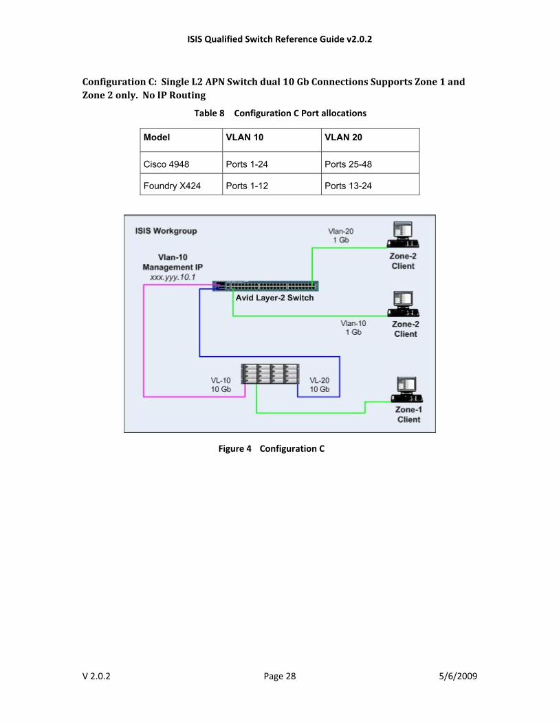
Configuration C: Single L2 APN Switch dual 10 Gb Connections Supports Zone 1 and Zone 2 only. No IP Routing
Table 8 Configuration C Port allocations
Model VLAN 10 VLAN 20
Cisco 4948 Ports 1-24 Ports 25-48
Foundry X424 Ports 1-12 Ports 13-24
Figure 4 Configuration C
V 2.0.2 Page 28 5/6/2009
ISIS Qualified Switch Reference Guide v2.0.2
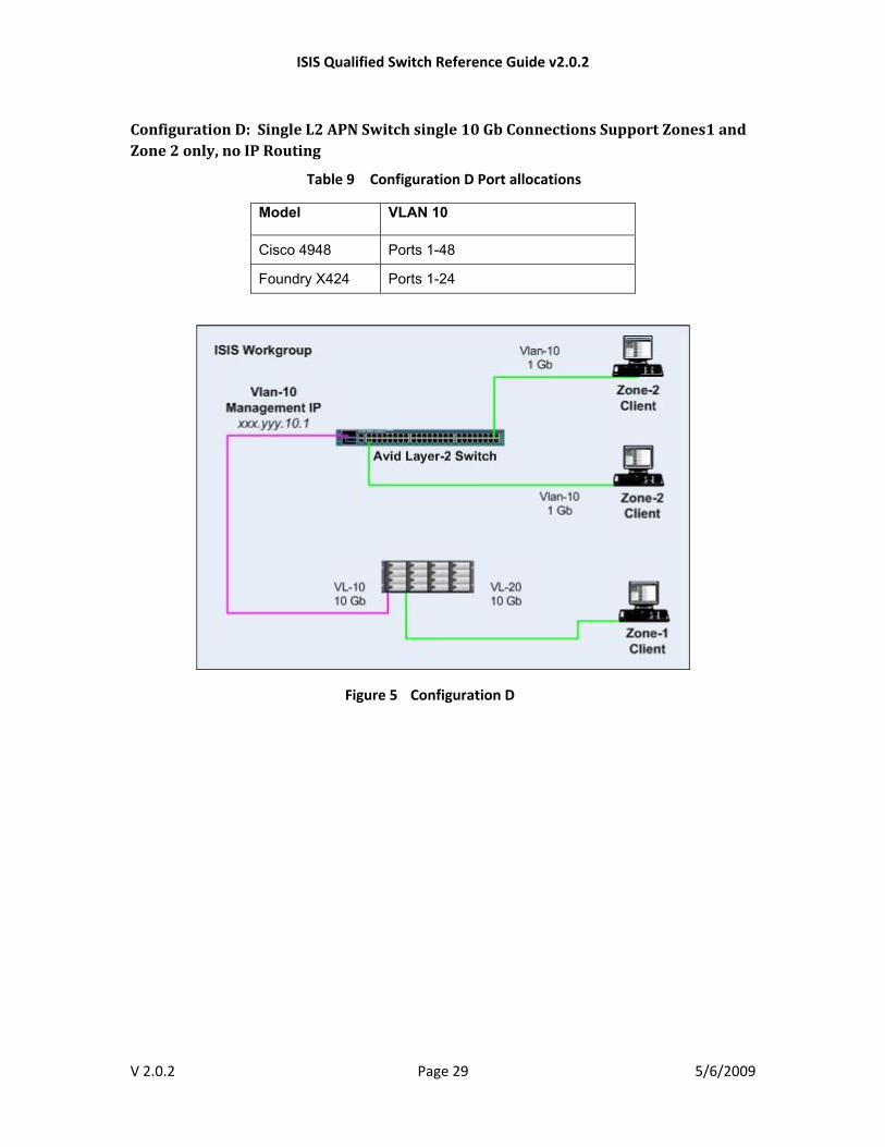
Configuration D: Single L2 APN Switch single 10 Gb Connections Support Zones1 and Zone 2 only, no IP Routing
Table 9 Configuration D Port allocations
Model VLAN 10
Cisco 4948 Ports 1-48
Foundry X424 Ports 1-24
Figure 5 Configuration D
V 2.0.2 Page 29 5/6/2009

ISIS Qualified Switch Reference Guide v2.0.2
Configuration E: L3 Switches with Router Redundancy
Table 10 Configuration E Port allocations
Model VLAN 10 VLAN 20 VLAN 30 House Network
Uplink (Link Aggregation)
VLAN 40 Zone 3 Test Port
Notes
Cisco 4948 Ports 1-22 Ports 23-43 Ports 45 to 48 (Ether Channel)
44 Two configs provided, one for each switch. Switch 1 Master on VLAN 10 and Backup on VLAN 20. Switch 2 Master on VLAN 20 and Backup on VLAN 10.
Foundry X424 Ports 1-10 Ports 11-19 Ports 21 to 24 (Trunk) 20 Two configs provided, one for each switch. Switch 1 Master on VLAN 10 and Backup on VLAN 20. Switch 2 Master on VLAN 20 and Backup on VLAN 10.
V 2.0.2 Page 30 5/6/2009

ISIS Qualified Switch Reference Guide v2.0.2
Figure 6 Configuration E
V 2.0.2 Page 31 5/6/2009

ISIS Qualified Switch Reference Guide v2.0.2
Table 11 Configuration E – Cisco 4900M Port Allocations
Model
VLAN 10 VLAN 20 Inter-switch Link
VLAN 30 VLAN 40 Zone 3 Test Port
House Network Uplink
Notes
Cisco 4900M
Ports 1/1-3, 2/1-20, where 1/1-2 are link aggregated
Ports 1/4-6, 3/1-16, where 1/4-5 are link aggregated
1/7 Ports 3/17-19
3/20 1/8 Two configs provided, one for each switch. Switch 1 Master on VLAN 10 and Backup on VLAN 20. Switch 2 Master on VLAN 20 and Backup on VLAN 10.
Figure 7 Configuration E – Cisco 4900M
V 2.0.2 Page 32 5/6/2009

ISIS Qualified Switch Reference Guide v2.0.2
V 2.0.2 Page 33 5/6/2009
Table 12 Redundant Switch Configuration Examples by ISIS VLAN
Foundry VRRPE* Cisco HSRP Cisco GLBP
Switch 1 ISIS VLAN 10
ip address 192.168.10.2 255.255.255.0 ip vrrp-extended vrid 10 backup priority 120 advertise backup ip-address 192.168.10.4
ip address 192.168.10.2 255.255.255.0 standby ip 192.168.10.4 standby priority 95 standby preempt
ip address 192.168.10.2 255.255.255.0 glbp 110 ip 192.168.10.4 glbp 110 preempt
ISIS VLAN 20
ip address 192.168.20.2 255.255.255.0 ip vrrp-extended vrid 20 backup priority 110 advertise backup ip-address 192.168.20.4
ip address 192.168.20.2 255.255.255.0 standby ip 192.168.20.4 standby priority 90
ip address 192.168.20.2 255.255.255.0 glbp 120 ip 192.168.20.4 glbp 120 priority 90
Switch 2 ISIS VLAN 10
ip address 192.168.10.3 255.255.255.0 ip vrrp-extended vrid 10 backup priority 110 advertise backup ip-address 192.168.10.4
ip address 192.168.10.3 255.255.255.0 standby ip 192.168.10.4 standby priority 90
ip address 192.168.10.3 255.255.255.0 glbp 110 ip 192.168.10.4 glbp 110 priority 90
ISIS VLAN 20
ip address 192.168.20.3 255.255.255.0 ip vrrp-extended vrid 20 backup priority 120 advertise backup ip-address 192.168.20.4
ip address 192.168.20.3 255.255.255.0 standby ip 192.168.20.4 standby priority 95 standby preempt
ip address 192.168.20.3 255.255.255.0 glbp 120 ip 192.168.20.4 glbp 120 preempt
*For Foundry VRRPE you must also specify the following Global Configuration: router vrrp-extended
Switch Vendor Commands
Table 13 Command Similarities and Differences Between Vendors
Foundry Cisco SMC
Entering Enable Mode en en Logging in automatically puts you in this mode
Entering Global Config Mode
conf t conf t configure
Enabling IP Routing Automatic if more than one router interface is defined
ip routing Ip routing
Changing IP addresses
You must remove the old IP address first using the “no ip address” command
New IP address automatically replaces old
New IP address automatically replaces old