avionicap - electronic concepts, inc. · hecr series avionicap ® ˜˜avionicap ® series minature...
TRANSCRIPT
HECR SERIESAvionicap ®
Avionicap ® Series Minature Metallized Polycarbonate - HermeticallySealed
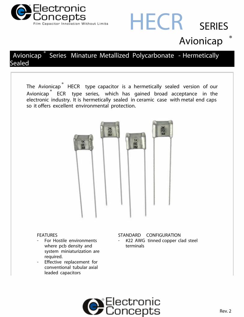
The Avionicap ® HECR type capacitor is a hermetically sealed version of ourAvionicap ® ECR type series, which has gained broad acceptance in theelectronic industry. It is hermetically sealed in ceramic case with metal end capsso it o�ers excellent environmental protection.
FEATURES STANDARD CONFIGURATION- For Hostile environments
where pcb density andsystem miniaturization arerequired.
- E�ective replacement forconventional tubular axialleaded capacitors
- #22 AWG tinned copper clad steelterminals
Rev. 2

Speci�cation Summary
Capacitance Range0.001µF to 1.0µF Capacitance is measured at 25°C and at, orreferred to, a frequency of 1KHz.
Capacitance ToleranceK=±10%, J=±5%, G=±2%, F=±1%
Operating Temperature Range-55ºC to 125ºC
Enclosure/ ConstructionHermetically sealed ceramic case with tinned metal end caps.
Voltage RatingDC working voltage ratings at +85ºC, 30VDC, 50VDC,100VDC, 150VDC, 200VDC and 300VDC. Voltage derating of1.25% per degree C is necessary to +125°C.
Quality ControlCapacitors are tested 100% for:o Capacitanceo Toleranceo Dissipation Factoro Dielectric withstanding Voltageo Insulation Resistanceo Seal Per Method 112 of MIL-STD-202 HECR - test condition AM39022/11 - also tested to condition C, procedure IIIa.
Process and inspection data are maintained on �le and availableon special request.
Environmental
Parameter Method ConditionVibration 204 DImmersion 104 CShock 213 IHumidity 106 -Thermal Shock 107 BLife 108 F
ReferenceMIL-STD-202
CharacteristicsInsulation ResistanceTemperature(°C) 25 85 125 MegaohmsxMicrofarads
100,000 7,000 700
InsulationResistance
Dielectric StrengthCapacitors will withstand a DC potential of 200% ratedvoltage for two (2) minutes without damage orbreakdown.Test voltage is applied and discharged through aresistance of 1 OHM per volt minimum, and at 25°C.
Capacitance ChangeTemperature(°C) -55 25 85 125PercentageChange(typical)
-2.5 0 ±1.0 ±2.0
CapacitanceChange
Dissipation FactorWhen measured at 1KHz, the dissipation factor will not exceed0.2% form +25° to 125°C
Rev. 2
Electrical Data
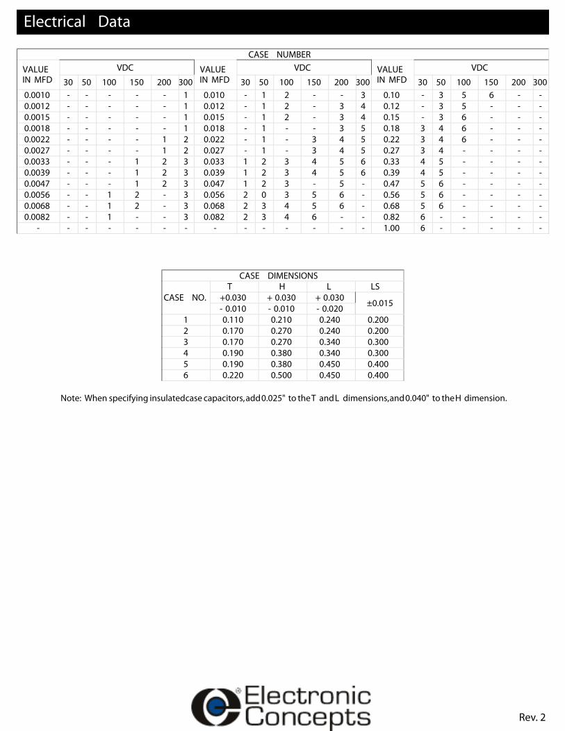
CASE NUMBER
VALUEIN MFD
VDC VALUEIN MFD
VDC VALUEIN MFD
VDC
30 50 100 150 200 300 30 50 100 150 200 300 30 50 100 150 200 3000.0010 - - - - - 1 0.010 - 1 2 - - 3 0.10 - 3 5 6 - -0.0012 - - - - - 1 0.012 - 1 2 - 3 4 0.12 - 3 5 - - -0.0015 - - - - - 1 0.015 - 1 2 - 3 4 0.15 - 3 6 - - -0.0018 - - - - - 1 0.018 - 1 - - 3 5 0.18 3 4 6 - - -0.0022 - - - - 1 2 0.022 - 1 - 3 4 5 0.22 3 4 6 - - -0.0027 - - - - 1 2 0.027 - 1 - 3 4 5 0.27 3 4 - - - -0.0033 - - - 1 2 3 0.033 1 2 3 4 5 6 0.33 4 5 - - - -0.0039 - - - 1 2 3 0.039 1 2 3 4 5 6 0.39 4 5 - - - -0.0047 - - - 1 2 3 0.047 1 2 3 - 5 - 0.47 5 6 - - - -0.0056 - - 1 2 - 3 0.056 2 0 3 5 6 - 0.56 5 6 - - - -0.0068 - - 1 2 - 3 0.068 2 3 4 5 6 - 0.68 5 6 - - - -0.0082 - - 1 - - 3 0.082 2 3 4 6 - - 0.82 6 - - - - -
- - - - - - - - - - - - - - 1.00 6 - - - - -
CASE DIMENSIONS
CASE NO.T H L LS
+0.030 + 0.030 + 0.030 ±0.015- 0.010 - 0.010 - 0.0201 0.110 0.210 0.240 0.2002 0.170 0.270 0.240 0.2003 0.170 0.270 0.340 0.3004 0.190 0.380 0.340 0.3005 0.190 0.380 0.450 0.4006 0.220 0.500 0.450 0.400
Note: When specifying insulatedcase capacitors,add0.025" to theT andL dimensions,and0.040" to theH dimension.
Rev. 2

Mechanical Data
Rev. 2

ADDITIONAL INFORMATIONBecause of it's sub miniature size, care must be taken to assure that the body temperature of the HECRcapacitor does not exceed 125°C during installation, so as not to adversely performance.
How To Order
TYPEMetallized Polycarbonate - Hermetically Sealed HECR
102CAPACITANCE IN PICOFARADSThe �rst digits are signi�cant, the third digit represents the number of zeros tofollow to express capacitance in picofarads.
A
TOLERANCEK=±10% J=±5% G=±2% F=±1% K
Sales
United States EuropeEastern:*Headquarters*P.O. Box 1278Eatontown,NJ 07724Tel: 732-542-7880Fax: 732-542-0524
Central:Illinois 630-668-8747
email: [email protected]:www.ecicaps.com
IrelandElectronic ConceptsEurope LTDIDA Estate, OughteradCo. Galway, Irelandtel: +353-91-552385,552432fax: +353-91-552387email: [email protected]:www.electronicconcepts.ie
Rev. 2
Marking And Date CodeAll capacitors are marked with company initials "EC", corporate logo or EC trademark—in addition to type HECR, capacitance,tolerance, rated DC working voltage and date code. The two digits of the date code represent the year, the second two digits theweek, i.e., 0952 is the 52nd week of 2009, 0902 is the second week of 2009. NOTE: Those supplied to MIL-C-39022/11 are markedin accordance with the military
Quality AssuranceMajor emphasis is placed on quality assurance. EC is an ISO 9001-2000 and AS9100:2004 Company. Raw materialinspection and the use of SPC manufacturing procedures assure the highest quality standards. Procedures are fully described in theEC Quality Control Manual. Electronic Concepts will continue to advance the state-of-the-art by utilizing leading edge technology,compact capacitor designs and establishing reliability procedures.
STYLE / VOLTAGEA=30VDC, B=50VDC, D=100VDC, E=150VDC, F=200VDC, H=300VDC