avl 415s smoke meter g002 (from s/n 2500)
TRANSCRIPT

AVL 415S SMOKE METER G002(FROM S/N 2500)
October 2011AT2483E, Rev.04
Maintenance Guide

The contents of this document may not be reproduced in any form or communicated to any third party without the prior written consent of AVL. While every effort is made to ensure its correctness, AVL assumes no responsibility neither for errors and omissions which may occur in this document nor for damage caused by them.All mentioned trademarks or registered trademarks are owned by their respective owners.
All rights reserved.
Copyright 2011 AVL List GmbH, Graz - Austria

3Warnings and Safety Instructions
Warnings and Safety Instructions
This manual contains important warnings and safety instructions to be observed by the user.
The product described in this manual is intended for one specific area of applica-tion which is defined in the instructions. The manual also explains the essential requirements for the application and operation of the product as well as safety precautions to ensure smooth operation. AVL can provide no guarantee or accept any liability for applications other than those described in this manual or for applications where the essential requirements and safety precautions are not met.
The product may only be used and operated by qualified personnel capable of observing the necessary safety precautions. All accessories and equipment used with the product must be supplied or approved by AVL. The operating prin-ciple of this product is such that the accuracy of the measurement results depends not only on the correct operation and functioning of the product, but also on a variety of peripheral conditions beyond the control of the manufacturer. The results obtained from this product therefore must be examined by an expert (e.g. for plausibility) before any action is taken that is based on the results.
All adjustment and maintenance work necessary on instruments when open and under voltage must be carried out by a professional technician who is aware of the dangers.
All repairs to the product are to be carried out by the manufacturer or qualified service personnel only.
When the product is in use, an expert must ensure that neither the test object nor the testing equipment is operated under conditions that could lead to damage or injury.
AVL 415S Smoke Meter G002 — Maintenance Guide

Warnings and Safety Instructions4
AVL 415S Smoke Meter G002 — Maintenance Guide

5Table Of Contents
Table Of Contents
Warnings and Safety Instructions................................................................................................................ 3
1 What You Should Know.................................................................................................... 7
1.1 Safety Instructions .................................................................................................................... 7
1.2 About the AVL 415S Smoke Meter........................................................................................... 7
1.3 About this Documentation ........................................................................................................ 8
1.3.1 Typografic Conventions ...................................................................................................... 8
1.3.2 We Want to Hear from You................................................................................................. 9
2 Maintenance .................................................................................................................... 11
2.1 Procedure ............................................................................................................................... 11
2.2 Service Intervals ..................................................................................................................... 12
2.2.1 AVL Service Engineer - Annual Maintenance Activities.................................................... 12
2.2.2 Service Engineer - Maintenance Schedule....................................................................... 13
2.3 Components ........................................................................................................................... 16
2.3.1 Disposal Instructions......................................................................................................... 16
2.3.2 Paper Feed Mechanism.................................................................................................... 172.3.2.1 Lubricating and Cleaning Intervals ................................................................... 182.3.2.2 Lubrication Points ............................................................................................. 19
2.3.3 Blackened Filter Area........................................................................................................ 22
2.3.4 Sampling Probe and Sampling Line.................................................................................. 23
2.3.5 Suction Unit ...................................................................................................................... 24
2.3.6 Reflectometer Head.......................................................................................................... 27
2.3.7 Clamping Lever and Ratchet Clip ..................................................................................... 28
2.3.8 Camshaft .......................................................................................................................... 30
2.3.9 Fine Filters ........................................................................................................................ 31
2.3.10 Filter Paper Transport and Spool Device.......................................................................... 32
2.3.11 Cooling.............................................................................................................................. 33
2.3.12 Pump ................................................................................................................................ 34
2.3.13 Pressure Reduction .......................................................................................................... 35
3 Checks.............................................................................................................................. 37
3.1 Sampling Volume Check ........................................................................................................ 37
3.1.1 Sampling Volume Check with AVL 4210 Instrument Controller........................................ 37
3.1.2 Sampling Volume Check via Terminal .............................................................................. 38
3.1.3 Check the Metering Pipe................................................................................................... 40
3.1.4 Examples of External Volume Measuring Systems .......................................................... 40
3.2 Leak Check............................................................................................................................. 41
3.2.1 Leak Check in SERVICE MODE (for Firmware Version 1.10 and Higher) ....................... 42
AVL 415S Smoke Meter G002 — Maintenance Guide

Table Of Contents6
4 Parts Lists ........................................................................................................................ 43
4.1 Consumables.......................................................................................................................... 43
4.2 Wear Parts.............................................................................................................................. 43
4.3 Spare Parts............................................................................................................................. 44
4.4 Maintenance Tools ................................................................................................................. 47
AVL 415S Smoke Meter G002 — Maintenance Guide

7What You Should Know
1 What You Should Know
1.1 Safety Instructions
This documentation contains important Warnings and Safety Precautions which should be observed by the user. Only by careful observance of these requirements and safety precautions, a smooth operation can be guaranteed.
1.2 About the AVL 415S Smoke Meter
Minimize your system downtimes by means of proactive measures. Our compe-tent service engineers will carry out inspections and maintenance with technical professionalism and cost efficiency in mind. Using original spare parts guaran-tees high system reliability. AVL preventive maintenance assures the highest possible availability of the system and devices.
Your benefits at a glance:
Best availability of equipment due to minimized down times
Guaranteed service quality through certified engineers
Easy budgeting due to transparent maintenance costs
Maintenance plans optimized for the used equipment and its applications
A typical preventive maintenance procedure comprises the following steps:
Visual check
Performance checks
Cleaning
Replacing wear parts
Calibration and re-adjustment
Calibration protocols
Failure diagnostics
Recommendation for repair
Required manpower:
The required time for an annual maintenance by an AVL Service Engineer is 6 hours.
Obviously, this time might depend of the usage and the environment conditions of the device.
The frequency we recommend in this document is based on normal operating hours (8 hours/working day).
Information
This manual refers to the maintenance of a Smoke Meter 415S.
Handling and actions are mainly the same as for the Generation 1 Smoke Meters, but the spare parts can be different.
AVL 415S Smoke Meter G002 — Maintenance Guide

What You Should Know8
1.3 About this Documentation
The documentation adresses service engineers who perform maintenance tasks of the AVL 415S Smoke Meter. All relevant tasks are described, all necessary wear and spare parts are listed.
Detailed knowledge about the device and the relevant safety regulations is essential.
For detailed information on the AVL 415S Smoke Meter see the corresponding manuals:
AT1240E 415S Smoke Meter, Operating Manual AT3648E 415SE Smoke Meter, Product Guide AT3803E 415SE Smoke Meter, Calibration Manual
The descriptions in this manual are based on the AVL Instrument Controller IC 4210.
If the DUI (Device User Interface) is used for the maintenance work, see also:
AT3569E 415S Smoke Meter, Device User Interface, User’s Guide
1.3.1 Typografic Conventions
Safety messages:
Additional messages:
WARNING
WARNING indicates a hazardous situation which – if not avoided – could result in death or serious injury.
CAUTION
CAUTION indicates a hazardous situation which – if not avoided – could result in minor or moderate injury.
NOTICE
This text indicates situations or operation errors which could result in property damage or data loss.
Information
This text indicates important information or operating instructions. Not observing these instructions could inhibit or impede you from succesfully completing the tasks described in this documentation.
AVL 415S Smoke Meter G002 — Maintenance Guide

9What You Should Know
Standard text styles:
Lists:
1.3.2 We Want to Hear from You
Your comments and suggestions help us to improve the quality and practical relevance of our manuals.
If you have any suggestions for improvement, please send them to:
We look forward to hearing from you!
Bold Parameters; control elements in windows and dialog boxes; important text
Italics Cross-references; foreign-language or new terms; wild-card for elements that need to be entered by the user, i.e. characters or text. If you read, for example, macro name, you are required to type the name of a macro.
UPPERCASE LETTERS Operating modes
Courier Programming examples; source code
Times New Roman Formulas
Menu | Option Description of how to select a menu item from a given menu
1.
2.
Step-by-step procedures with a given sequence
• One-step instructions
Unordered series of concepts, items or options
–
–
AVL 415S Smoke Meter G002 — Maintenance Guide

What You Should Know10
AVL 415S Smoke Meter G002 — Maintenance Guide

11Maintenance
2 Maintenance
2.1 Procedure
When the device is put to average use, we recommend:
1. Each time the paper is changed, perform the following steps:
– Inspect the reflectometer head - clean if necessary (do not forget to clean also the light gate 1).
– Inspect the two fine filters and replace if there are any signs of soiling.
– Inspect the blackened filter area.
– Perform a leak check.
– Check white value disk for soiling and clean if necessary.
– Lubricate moving parts of the camshaft and the ratchet clip by using Teflon lubricant oil (material number: HS0064) or Teflon lubricant spray (material number: HS0058).
2. After 300 operating hours or 10 000 measurements (corresponds to 5 … 10 paper rolls - material number HP0153SP) do the following:
– Check the reflectometer head.
– Check the sampled volume.
– Clean sampling line tube with ultra-clean, oil-free and water-free com-pressed air.
– Clean the light gate 1 with ultra-clean, oil-free and water free com-pressed air.
– Check filter mat for cooling air.
– Check the ratchet clip and the clamping lever.
– Carry out all the activities described in the following sections.
– Replace all fine filters.
– Clean and lubricate moving parts of camshaft and ratched clip using Teflon lubricant spray (material number HS0058) or Teflon lubricant oil (material number HS0064).
– Check pump noise and check nominal pump flow.
NOTICE
For permanent operation of the measuring device (fully automated endurance runs, 24 h/day, 6 … 7 days/week), a service is recommended every 3 weeks. A full service or replacing the pump is recommended every 3 months.
AVL 415S Smoke Meter G002 — Maintenance Guide

Maintenance 12
2.2 Service Intervals
2.2.1 AVL Service Engineer - Annual Maintenance Activities
Component / Test Lifetime / Service interval
Maintenance Replacement
Leak check Annually For checks of sample lines and probes:
supported on SERVICE MODE only perform with sampling probe & lineSpecial sampling
–
Reflectometer head Annually Check and clean or replace if necessary.
Adjustment if necessary and cali-bration.
Every 2 years
Light gate 1 Annually Check and clean if necessary. If damaged, replacement is done by an AVL Service Engineer.
Camshaft Annually Check and clean or replace if necessary.
Every 2 … 3 years or after 3 000 operating hours.
Fine filters Annually Replace. Annually
White value plate Annually Clean the deposit on the standard. If necessary.
Filter paper Annually Check the homogeneous black-ening with exactly delineated round contour.
–
Sealing ring of the suction unit
Annually Check there is no deposit, clean if needed.
Glue the sealing rings into the clamping device (suction unit).
Check the sealing ring for defects and correct sealing ring position.
Replacement of the sealing rings if damaged.
Clamping piecerolls, axlespress fit bushbearing
Annually Clean and lubricate all points. If necessary.
Sampling probe, sampling line
Annually Check and clean. 1 000 – 2 000 operating hours.
Filter mat Annually Replace. Annually
Check sampled volume Annually Check. Replacement of the glass caliber of the volume tester is necessary when it is scratched, or contami-nated with dirt.
Adjustment of the trans-port paper mechanism
Annually Function check and adjustment necessary every time spare parts are exchanged.
–
Adjustment of the slip clutch
Annually Check the tension and adjustment if necessary.
–
Ratchet clip Annually Replace. Annually
Tab. 1
AVL 415S Smoke Meter G002 — Maintenance Guide

13Maintenance
2.2.2 Service Engineer - Maintenance Schedule
For the disposal of environmentally sensitive substances, see the AVL 415S Smoke Meter Operating Manual, chapter Disposal of Environmentally Sensitive Substances.
Clamping lever Annually Visual check. If damaged or if any part is bent off.
Pump Annually Check and replace if necesary. Every 2 000 - 3 000 oper-ating hours.
Nipple & hose connec-tions
Annually Replace. Annually
Cleaning of electronical boards
Annually Clean with high purity compressed air.
If necessary or defective.
Check valve Annually Check and replace if necesary. Annually
Pressure reduction assembly
Annually Check. After assembly.
Pressure switch of shop air option
Annually Check and adjust if necessary. Annually
Component / Test Lifetime / Service interval
Maintenance Replacement
Tab. 1
WARNING
Fire hazard
When using the required appliances like sprays, mounting pastes, lubricants, always observe the relevant handling instructions and safety measures of the various products.
All sprays used are a fire hazard and highly inflammable. Installation work using the appliances on and inside measurement devices and on test beds must only be carried out on cooled-down parts and in well ventilated areas.
NOTICE
The compressed air used to clean, has to be absolutely free from oil, water, and particles.
AVL 415S Smoke Meter G002 — Maintenance Guide

Maintenance 14
Component / Test Lifetime / Service interval
Maintenance Replacement Procedure
Leak check Minimum every day.
After every filter paper change.
After every manipu-lation of the paper transport.
Before & after every volume tester cali-bration.
For checks of sample lines and probes:
supported on SERVICE MODE only perform with sampling probe & line and special sampling
– Section Leak Check on page 41
Reflectometer head Every time the filter paper is exchanged.
Check and clean if necessary with a puffer or a soft brush or with compressed air.
Every 2 years Section Reflecto-meter Head on page 27
Light gate 1 Every time the filter paper is exchanged.
Check and clean if necessary with compressed air.
If damaged – Replacement is done by an AVL Service Engi-neer.
Camshaft Every time the filter paper is exchanged.
Check and clean if necessary with compressed air.
Every 2-3 years or after 3 000 oper-ating hours.
Section Camshaft on page 30
Fine filters Every time the filter paper is exchanged.
Check. Following the usage conditions.
Section Fine Filters on page 31
White value plate Every time the filter paper is exchanged.
Clean the deposit on the standard with a soft, wet cloth.
– Section Clamping Lever and Ratchet Clip on page 28
Filter paper Every time the filter paper is exchanged.
Check the homoge-neous blackening with exactly delineated round contour.
Check the backside of the filter paper fpr back flushed particles.
– Section Blackened Filter Area on page 22
Sealing ring of the suction unit
Minimum every 5 times of filter paper exchanged.
Check if there is no deposit, clean if necessary with a soft or a damp cloth.
Glue the sealing rings into the clamping device (suction unit) with Adhesive 3M-B20.
Check the sealing ring for defects and correct sealing ring position.
Replacement of the sealing rings if damaged; in this case also order mounting ring 30 mm.
Section Suction Unit on page 24
Tab. 2
AVL 415S Smoke Meter G002 — Maintenance Guide

15Maintenance
Clamping piecerolls, axlespress fit bushbearing
Required after 4-5 exchanges of the filter paper roll,
or after 10 000 measurements,
or after 300 oper-ating hours of the pump.
Clean and lubricate all points with Teflon lubricant spray or Teflon lubricant oil.
If necessary. Section Lubri-cating and Cleaning Intervals on page 18, section Lubrica-tion Points on page 19
Sampling probe, sampling line
For Diesel engine: minimum once a week,
or after 300 oper-ating hours of the pump.
For low meas. emis-sion: once a week
For high HC concentration:everyday
Check and clean with compressed air.
1 000 – 2 000 operating hours.
Section Sampling Probe and Sampling Line on page 23
Filter mat Every 300 oper-ating hours of the pump,
or after 10 000 measurements
Visual check and clean if necessary with compressed air.
- Section Cooling on page 33
Check sampled volume
Recommended: every 300 operating hours of the pump,
or after 10 000 measurements.
Necessary:after 1 000 oper-ating hours.
Check recommended after:
Installing/reinstalling the device on the test bed.
When changing the dead volume.
After cleaning the device from the soot contamination.
After repairing the device.
Re-adjustment.
Replacement of the glass caliber of the volume tester is necessary if it is scratched or contaminated with dirt.
Section Sampling Volume Check on page 37
Adjustment of the transport paper mechanism
Every 1 000 operating hours.
Function check and adjustment is neces-sary every time spare parts are exchanged. Clean disassembled parts in ultrasonic bath or replace them.
– Section Suction Unit on page 24
Adjustment of the slip clutch
Every 1 000 operating hours
or once a year.
Check the tension and adjust if necessary.
– Section Filter Paper Transport and Spool Device on page 32
Component / Test Lifetime / Service interval
Maintenance Replacement Procedure
Tab. 2
AVL 415S Smoke Meter G002 — Maintenance Guide

Maintenance 16
2.3 Components
2.3.1 Disposal Instructions
Ratchet clip Every 300 operating hours.
Every 6 months .
Visual check and clean if necessary.
When ratchet clip rolls damaged or deformed.
Section Clamping Lever and Ratchet Clip on page 28
Pump Every 1 000 operating hours.
Every 2 000 - 3 000 operating hours.
Flow check.
Check and replace if necessary.
Every 2 000 - 3 000 operating hours.
Section Pump on page 34
Electrical boards Once a year
or if contaminated.
Visual check.
Clean with compressed air.
– –
Pressure reduction assembly
Once per week
or after assembly.
Check and adjust if necessary.
–
Component / Test Lifetime / Service interval
Maintenance Replacement Procedure
Tab. 2
NOTICE
Dispose of used filter paper rolls, fine filters, hose connectors and chemical agents (e.g. bonding agents or sprays) in accordance with the statutory require-ments applicable in your country.
Remember that hoses and hose connectors contain fluorine. Observe the statu-tory requirements in your country when you wish to dispose of this product or components thereof (e.g. directives on the disposal of electronic waste).
Observe the handling instructions, application notes, storage and transport instructions, instructions for disposal, and safety instructions of the products as well as the country-specific regulations.
All appliances have to be treated as hazardous waste.
For detailed information on disposal instructions see the AVL 415S Product Guide.
AVL 415S Smoke Meter G002 — Maintenance Guide

17Maintenance
2.3.2 Paper Feed Mechanism
NOTICE
The lifetime of the paper feed mechanism components depends heavily on correct on-site maintenance. If the following activities are not done in time, the lifetime of the paper feed mechanism will be considerably reduced. The mentioned intervals are typical, recommended values that might even be shorter if the system is exposed to additional stress caused by heavy contamination with particulate matter or by contamination present in the ambient air.
Basically, the following applies: If you notice that "lubricant oil or lubricant grease" is no longer "liquid" at the lube points, or if the deposits have already turned black or exhibit an "almost solid or stiff consistency", all moving parts have to be completely cleaned to remove any abrasion, deposits, residues of lubrication agents etc. Furthermore, a subsequent re-lubrication of the system is necessary.
A complete cleaning and re-lubrication of all moving parts is also required (immi-nent danger) if you can hear "squeaky", "rubbing", "grating", "crunching" or "grinding" noises during paper feed.
Information
In general, the currently defined Teflon lubricant oil can be used in the same way as it has been used in the past. However, it is absolutely necessary to adhere to the defined lubricating and cleaning intervals.
Points or system parts for which lubricant grease should preferably be used or which only require the use of lubricant oil (or lubricant spray) are marked sepa-rately in the following illustrations.
If the measuring system is not used continously (means approx.5 days a week; approx. 50 weeks a year) the general use of HS0064 as lubricant agent is recommended.
Lubricating agents:
Teflon Lubricant Oil (material number HS0064)
Teflon Lubricant Spray (material number HS0058)
Lubricant Grease OKS 260 (material number HS0071); only for systems which are in permanent use (7 days a week, > 300 days a year).
AVL 415S Smoke Meter G002 — Maintenance Guide

Maintenance 18
2.3.2.1 Lubricating and Cleaning Intervals
1. After 3 to 4 paper rolls (material number HP0153):
– Lubricate the moving parts of the paper feed mechanism with Teflon lubricant oil or Teflon lubricant spray, as currently given in the manual.
2. After approx. 5 to 10 paper rolls or after 300 operating hours or every 10,000 measurements (whatever occurs sooner):
– Perform a simple cleaning of the parts of the paper feed mechanism to remove the coarsest soiling.
– Then lubricate all moving parts (with lubricant grease and/or with lubri-cant oil or lubricant spray).
3. After (every) approx. 50 paper rolls:
– Complete cleaning of all parts of the paper feed mechanism to remove all deposits and re-lubrication of all parts (all rotating and sliding parts; this also concerns the inside parts of the shafts and rollers that can be taken apart).
– Check the parts for wear and replace any affected components.
– Perform a complete cleaning of the device to clear any kind of contam-ination present such as paper fibers, particulate matter or any other system contamination.
4. After (every) approx. 100 / 300 (200) paper rolls:
– Check and, if required, replace the PU roller and the ratchet clip rollers (if required, also the entire assembly including axles and rollers - see Fig. 4 on page 22 - Pos. 110 to 150, or alternatively, replace the entire ratchet clip).
– Perform all activities of step 3.
5. After approx. 1 000 paper rolls:
– Order an AVL service engineer: parts, such as the motor, camshaft bearings, ratchet clip, clamping lever, suction unit or other worn-out component parts, have to be checked by an AVL service engineer, who will then decide if replacement is necessary.
NOTICE
The elastomer roller (Fig. 4 on page 22) on the ratchet clip cannot be cleaned. This part has to be disassembled before cleaning the other mechanical parts or it has to be replaced.
After cleaning of all parts they must be lubricated as shown in Fig. 1 to Fig. 4.
AVL 415S Smoke Meter G002 — Maintenance Guide
19Maintenance
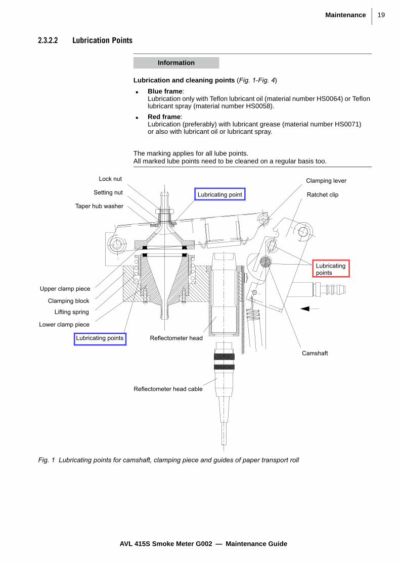
2.3.2.2 Lubrication Points
Information
Lubrication and cleaning points (Fig. 1-Fig. 4)
Blue frame: Lubrication only with Teflon lubricant oil (material number HS0064) or Teflon lubricant spray (material number HS0058).
Red frame: Lubrication (preferably) with lubricant grease (material number HS0071) or also with lubricant oil or lubricant spray.
The marking applies for all lube points. All marked lube points need to be cleaned on a regular basis too.
Fig. 1 Lubricating points for camshaft, clamping piece and guides of paper transport roll
Camshaft
Lubricatingpoints
Lubricating points
Lubricating point
Lock nut
Setting nut
Taper hub washer
Clamping lever
Ratchet clip
Upper clamp piece
Clamping block
Lifting spring
Lower clamp piece
Reflectometer head cable
Reflectometer head
AVL 415S Smoke Meter G002 — Maintenance Guide

Maintenance 20
Fig. 2 Lubricating points for camshaft bearing and ratched clip roll
Pos 050
Pos 030
Pos 020
Pos 040
Pos 060
Lubricatingpoints
Lubricatingpoints
Clamping lever
Ratchet clip
Fastening screw fordrive unit
Positioning bracketfor motor and light barrier
Fastening screw for camshaft
<<< Housing door >>>
Lube point: press fit bush Pos. 40
AVL 415S Smoke Meter G002 — Maintenance Guide

21Maintenance
1 .....Twin-sided adhesive film
2 .....Clamping lever roll
3 .....Axis II
4 .....Roll I (2x)
5 .....White value sheet
Fig. 3 Lubricating points on clamping lever
Pos 040
Pos 010
Pos 020
= =
Pos 030
1
1
5
2 3 4
Lube points
Lube points
Lube points
Information
These points on the clamping lever only need to be lubricated "sparingly" approx. every 50 paper rolls.
Please remove any unnecessary or excess oil or grease.
AVL 415S Smoke Meter G002 — Maintenance Guide

Maintenance 22
2.3.3 Blackened Filter Area
The filter area must show homogeneous blackening with an exactly delineated, round contour with a diameter of 29.8 ± 0.1 mm.
Spots with blurred
edges
Blurred edges indicate leaks in the suction unit.
• Check the suction unit (see Suction Unit on page 24).
Local dark spots Dark spots indicate the formation of condensate or heavy soot deposits:
1. Check the gas path from the sampling probe to the filter paper.
2. Purge frequently.
3. Reduce the sampling volume and/or use the heating option.
4. Always replace the fine filter.
Fig. 4 Lubricating points for ratched clip roll
Pos 150
Pos 130
Pos 120
Pos 140
Pos 110
Lubricatingpoint
Lubricatingpoint
Lube points(axles, inside)
Lube points (rollers, inside and outside)
Fig. 5 Blackening of the filter
AVL 415S Smoke Meter G002 — Maintenance Guide

23Maintenance
2.3.4 Sampling Probe and Sampling Line
Leak check • Check the thread, sealing surfaces and clamping points of the line fittings and sampling line itself for leaks.
Check for soot
deposits
1. Clean out the sampling path with cleaned, oil and condensate-free com-pressed air.
2. Replace the sampling lines if necessary.
Sampling probe 1. Dismantle the exhaust gas sampling probe at least once a year if not more often, depending on use.
2. Remove soot and other deposits.
3. Lubricate the thread and clamping points with lead-free anti-sticking agent (e.g. with assembly spray SF01, material number HK0029).
Sampling probe standard Material number: BO3144SP
Sampling line In exceptional cases, the surface characteristics of soot deposits may result in reduced measurement value accuracies (because soot is deposited as the gas is drawn through and not blown out completely again during purging).
Depending on the operating states of the engine and/or the kind of particles, deposits in the hose can develop that cannot be removed using compressed air.
This deposit can "filter" particles out of the measurement gas and cause measurement deviations.
NOTICE
Disconnect the probe and line from the AVL 415S before cleaning them with compressed air.
Under no circumstances the gas path from upper clamping piece of the suction unit to direction SAMPLE OUT may be pressurised with compressed air (see Fig. 3 page 27 in the operating manual).
If compressed air is used to clean the suction unit, the clamping pieces, tube and the 2/2 way valves MV3 (and MV4), these valves must be "electrically opened" – this is only possible by switching on the according valve in the service menu using the SERVICE MODE (1 = "SWITCHED ON").
Never apply compressed air in this case, if the filter paper is mounted.
Do not blow pollutants into the ambient air. Dispose of pollutants in accordance with your local regulations.
NOTICE
Apply the paste sparingly so that none gets into the gas path!
Fig. 6 Sampling probe standard (Available in the eSparesTM Webshop)
AVL 415S Smoke Meter G002 — Maintenance Guide

Maintenance 24
1. Carry out a reference measurement with a "new" line, if it seems to be nec-essary.
2. Replace the sampling lines (Viton hoses) regularly.
Recommended replacement intervals: every 1 000 … 2 000 operating hours.
The material number depends on the length of the sampling line
2.3.5 Suction Unit
Clamp piece
tracks
1. Check the friction conditions in the clamp piece tracks.
2. Remove the hose from the upper clamp piece
3. Release the clamping lever and open it completely.
4. Check the clamp piece tracks for easy movement.
5. If necessary, lubricate track (ex-works: Teflon lubricant spray - part number HS0058, Teflon lubricant oil - part number HS0064, or Lubricant grease OKS 260 - part number HS0071)
Fig. 7 Sampling line
Information
Heavier soot deposits can occur when using new sampling lines for the first time straight from the factory and this can also reduce the recorded FSN values.
The lower the measurement values, the higher, the requirement for repeatability, and reproducibility.
The greater is the influence of the soiling along the entire sampling path.
Fig. 8 View of the suction unit in the device
Information
Remember the hose clip when disconnecting and reconnecting the hose.
AVL 415S Smoke Meter G002 — Maintenance Guide

25Maintenance
Sealing ring 1. Check the sealing rings for damage or deposits of paper fibres.
2. Remove paper fibres with a soft, damp cloth.
3. Replace sealing rings if damaged. Never re-glue used sealing rings.
4. Use only the defined adhesive for glueing the sealing rings. Carefully follow the instructions of the glue manufacturer for the usage of the glue.
5. Close the clamping lever (remember the hose clamps).
Gasket 30mm 4152X38./C00.0Material number: YM3499SP
Mounting ring We recommend ordering this part for fixing the gasket (material number YM3499SP) into the suction unit of the clamping and drive mechanism:
Mounting ring 30 mm 4152X41./C00.0Material number: YM3516SP
NOTICE
Apply only a thin film of lubrication - only into region between the upper and lower clamping piece (Fig. 8), so that no oil can reach the sealing rings.
Never clean the elastomer parts (sealing rings) in an ultrasonic bath. Replace them only if necessary.
CAUTION
Danger of pinching
Be careful when pressing the paper feed button not to get anything pinched in the clamping mechanism and to avoid defects on the clamping mechanism.
Fig. 9 Sealing ring for suction unit (Available in the eSparesTM Webshop)
Fig. 10 Mounting ring 30 mm 4152X41./C00.0 (Available in the eSparesTM Webshop)
AVL 415S Smoke Meter G002 — Maintenance Guide

Maintenance 26
Suction unit Suction unit 4152W15./C00.0Material number: BO3774SP
Clamping lever
adjustment
1. Start a paper feed and check that the clearance between the camshaft and the paper transport shaft is 25 + 0.5 mm.
If aligned correctly, the tip of the support clip points to the center of the paper transport shaft. You should also be able to press the clamping lever down by 0.5 mm.
2. Adjust if necessary with the setting nut and secure with the lock nut (see Fig. 12 on page 26).
– If the clearance is too large, the retaining ring does not open wide enough and there is a risk that soot will be scraped off.
– If the clearance is too small, the leakage factor will be high because the clamping force is insufficient.
3. Check the friction in the tracks/bearings of the ratchet clip-camshaft in rela-tion to one another and:
– If necessary, lubricate track (ex-works: Teflon lubricant spray - material number HS0058, Teflon lubricant oil - material number HS0064, or Lubricant grease OKS 260 - material number HS0071); see chapter 13 in the Operating Manual.
Fig. 11 Suction unit 4152W15./C00.0 (Available in the eSparesTM Webshop)
Fig. 12 Clamping lever adjustment
AVL 415S Smoke Meter G002 — Maintenance Guide

27Maintenance
2.3.6 Reflectometer Head
Glass area The glass area on the face must not be soiled, scratched or damaged.
1. Check whether there are any soot deposits or filter paper fibres each time you change the filter paper.
2. Clean the reflectometer head carefully with a puffer and a soft brush, with ultra-pure pressurized air, or replace it.
Jacket surface • Check the blackening of the visible jacket surface of the inside reflectometer head housing between the glass area and the end of the reflectometer head. It must be even (no scratches…).
Measuring head The polymeric material of the measuring head must be clear, transparent and colourless - no colouring is allowed.
• Replace the measuring head, if the polymeric material is coloured yellowish or brownish.
We recommend replacing the reflectometer head every 2 years:
Meas. head N°1 687 224 606Material number: EZ0104SP
Fig. 13 Reflectometer head
NOTICE
The blackened surface of the housing (inside) and the transparent optical surfaces of the reflectometer head must never be scratched.
Fig. 14 Meas. head N°1 687 224 606 (Available in the eSparesTM Webshop)
AVL 415S Smoke Meter G002 — Maintenance Guide

Maintenance 28
2.3.7 Clamping Lever and Ratchet Clip
The bearings of the clamping lever itself and of the paper transport shaft must not be worn.
The flexible transport roll on the paper transport axis of the ratchet clip must not be damaged.
The foam block must be elastic and the white value plate must press flat against the entire surface of the reflectometer head face when the clamp is closed.
1. Check the surface of the white value plate:
The surface has to be clean and must not be scratched.
2. Clean with a soft, wet cloth if necessary or replace white value plate.
3. Check the performance of the ratchet clip rolls: the surfaces must be clean, lubricated and the surface shall look as polished - no scratches, cuts, nuts… are allowed (see Fig. 16 on page 28).
4. Otherwise clean all parts of the ratchet clip, replace the ratchet clip rolls, lubricate all moved parts.
1 .... Clamping lever
2 .... Ratchet clip
Fig. 15 View of the clamping lever
o
Fig. 16 Ratchet clip rolls
NOTICE
Never lubricate the elastomer part on the transport roll.Remark: a complete exchange of the rachet clip is recommended.
Never clean the elastometer part of the transport roll in an ultrasonic bath. This part can not be cleaned but only replaced.
2
1
AVL 415S Smoke Meter G002 — Maintenance Guide

29Maintenance
Paper transport roll Paper transport roll completeMaterial number: BW5409
Standard transport rollMaterial number: YM3687
For measurements with high hydrocarbon contents of the particle an alter-native transport roll is available:
Alternative transport roll Material number: YM6962.
Ratchet clip We recommend replacing the ratchet clip during the annual preventive mainte-nance.
Ratchet clip compl. G002 4152W52Part Number: BO6671SP
NOTICE
This roll is not recommended as standard transport roll and shall not replace YM3687.
o
1 .....Transport roll
2 .....Paper transport roll complete
Fig. 17 Paper transport roll complete
21
Fig. 18 Ratchet clip complete G002 4152W52 (Available in the eSparesTM Webshop)
AVL 415S Smoke Meter G002 — Maintenance Guide

Maintenance 30
Ratchet clip roll 4152X63./C00.0Part Number: YM3804
Clamping lever Clamping lever compl. G002 4152W50Part Number: BO6439SP
2.3.8 Camshaft
The camshaft must be replaced if the surface of the tappet is roughened or flat-tened.
1. Check that the resting position of the camshaft is < ±10 deg.
2. Keep in mind that the camshaft bearing in the bearing block must not be chipped.
Fig. 19 Ratchet clip roll 4152X63./C00.0 (Available in the eSparesTM Webshop)
Fig. 20 Clamping lever complete G002 4152W50 (Available in the eSparesTM Webshop)
o
1 .... Defective camshaft surface
2 .... Defective ratched clip rolls, caused by defective camshaft surface
Fig. 21 Camshaft
1 2
AVL 415S Smoke Meter G002 — Maintenance Guide

31Maintenance
3. Check that the camshaft is secured on the flattened part of the motor shaft if the camshaft is replaced or was dismounted:
The setscrew in the camshaft must be screwed tight and secured (ex-works: Loctite 245, Part Number HD0016).
4. Lubricate the bearing of camshaft in clamping lever using Teflon lubricant spray (part number HS0058) or Teflon lubricant oil (part number HS0064), or Lubricant grease OKS 260 (material number HS0071) - according to the points indicate on Fig. 22 below.
2.3.9 Fine Filters
• Check the two fine filters every time the filter paper is exchanged.
– For normal operation:We recommend replacing these two fine filters as soon as they become blackened.
– When high hydrocarbon contents as oil and fuel occur in the exhaust: We recommend replacing these two fine filters every time the filter paper is exchanged.
Fig. 22 Lubricating points for camshaft, clamping piece and guides of paper transport roll
Camshaft
Lubricatingpoints
Lubricating points
Lubricating point
Lock nut
Setting nut
Taper hub washer
Clamping lever
Ratchet clip
Upper clamp piece
Clamping block
Lifting spring
Lower clamp piece
Reflectometer head cable
Reflectometer head
AVL 415S Smoke Meter G002 — Maintenance Guide

Maintenance 32
Fine Filter We recommend replacing the fine filters during the annual preventive mainte-nance:
Pre-filterMaterial number: MF0478SP
2.3.10 Filter Paper Transport and Spool Device
The spool roll is driven by the supply roll by means of a slip clutch and a chain drive; the driving torque of the spool roll is determined by the pre-tensioning of the compression spring on the supply roll axis:
NOTICE
Remounting the parts, avoid any drilling forces on tubing and upper clamping piece.
Fig. 23 Pre-filter (Available in the eSparesTM Webshop)
CAUTION
Danger of burns and pinching!
In heated devices there is a danger of burns. The temperature of the compo-nents inside a device can reach up to 70°C.
There is a danger of pinching your fingers in the clamp when inserting the filter paper. Be particularly careful!
When working on the filter paper transport and spool, take care not to get your fingers pinched in the chain drive!
Fig. 24 Inside the device, the paper transport mechanism
AVL 415S Smoke Meter G002 — Maintenance Guide

33Maintenance
1. Check this function particularly when the supply roll is almost empty and the spool roll full and, if necessary, adjust the pretension of the compression spring accordingly (torque at spool roll 20 to 22 Ncm).
For adjustment, see AT1240 415S Smoke Meter Operating Manual. After adjustment fix it with the counter nut and seal it (see also Fig. 25 on page 33).
2. Do not pretension the compression spring more than necessary so that the traction force on the filter paper is kept to a minimum.
3. Make sure the roller holder of the used paper spool does not rub against either the supply roller or the paper strip to be spooled onto it.
The length of a filter paper feed should be between 47 and 53 mm. (tolerances: minimum 43 mm, maximum 57 mm).
4. Do not lubricate chain and chain wheels (in particular the friction surface of the clutch must be "dry", see Fig. 25).
2.3.11 Cooling
The cooling air flows in and out on the underside of the device through filter mats.
1. Clean the mats with compressed air.
2. Replace heavily soiled mats.
Filter Mat We recommend replacing the filter mat during the annual preventive mainte-nance:
Filter mat set 4152W25./C00.0Material number: BO3899SP
Fig. 25 View of the filter mat and the paper transport adjustment
Fig. 26 Filter mat set 4152W25./C00.0 (Available in the eSparesTM Webshop)
AVL 415S Smoke Meter G002 — Maintenance Guide

Maintenance 34
2.3.12 Pump
Pump noise Depending on the application, due to permanent use at automatic tests, pres-sures at or in the system, pressure pulsations of the exhaust gas, exhaust gas composition and corrosivity of the exhaust gases etc. the pump performance is affected, this can influence the service life time.
1. Check whether the noise of the pump is atypically or whether the pump is very noisy.
2. If yes, exchange the pump or at least check the flow of the pump.
Pump flow Typically the pump flow shall be in a region between 10 … 13 l/min (if system is heated: up to 15 % lower values related to ambient temperature of 20 °C).
Test with probe line mounted – maximum 3 m length, clean filter paper inserted, inlets and outlets of the flow are at ambient pressure. Flow measurement at inlet or outlet of the measuring system.
A simplified pump function check (as well as a check of the flow behaviour in the device) is also possible in the Smoke Meter itself:
Flow control: no sampling hose or exhaust gas disposal hose is connected.
The device is already switched on and warmed up or device is switched on in Service mode.
Setting: single measurement, sampling time is set to 120 sec (2 min).
1. Activate a measurement in measurement mode and the device will take in air for 2 min.
2. Switch to the Volume Calibration menu.
– The sampled volume "Vol 415 at 25 °C/1 bar" should be between 20000 and 26000 ml in unheated operation, which matches a pumping capacity of 10 … 13 l/min.
– In heated operation, the measured value range is about 15 % smaller (i.e. approx. 17000 to 23000 ml).
Fig. 27 Back side of the Smoke Meter AVL 415S
AVL 415S Smoke Meter G002 — Maintenance Guide

35Maintenance
Pump
components
1. After about 1 000 operating hours or after 3 months at permanent system usage at automatic tests, clean or replace the orifices, membranes, dia-phragms and pump heads.
2. For reassembling the pump, follow the service memo 15/06.
Diaphragm pump We recommend replacing the pump every 2 000 to 3 000 operating hours:
Diaphragm pump type 7015ZV/24VDCMaterial number: MV0207SP
2.3.13 Pressure Reduction
Pressure
Reduction
• Clean the unit once per month with compressed air.
Information
With a sampling line with a maximum length of 3 m connected to MV3 or MV4, the flow rate may be reduced by no more than further 10 %.
If the Special Sampling Option (Sample Out Box) is installed, the flow rate can also drop by around 10 %.
Fig. 28 Diaphragm pump type 7015ZV/24VDC (Available in the eSparesTM Webshop)
Fig. 29 Pressure Reduction Unit
Probe for connectioninto the exhaustduct
Probe to SmokeMeter, 30 and 70 cm long variants possible
Extension for coolingthe exhaust gas
Extensions for coolingthe exhaus gas
Check valve 30cm probe with connection
to Smoke Meter tubings
AVL 415S Smoke Meter G002 — Maintenance Guide

Maintenance 36
Check Valve 1. Regularly clean/replace one check valve in rotation with the other one.
2. Replace the check valves once a year.
3. Perform a visual check after every assembly and at least once per week.
AVL 415S Smoke Meter G002 — Maintenance Guide

37Checks
3 Checks
3.1 Sampling Volume Check
This function is used to compare the amount of the sampling volume with an external measurement system.
This check can be performed:
with AVL 4210 Instrument Controller; see Sampling Volume Check with AVL 4210 Instrument Controller on page 37.
via terminal; see section Sampling Volume Check via Terminal on page 38.
via device user interface DUI; see AVL 415SE Smoke Meter Calibration, User’s Guide (material number AT3803).
3.1.1 Sampling Volume Check with AVL 4210 Instrument Controller
1. Enter measurement values.
2. Compare measurement values.
Information
In heated devices, the calibration should be carried out when the device is heated. For this you need the Retrofit Kit (material number: BO3776). Remark: this is a standard part of the AVL 408S Volume Tester, if delivered after 1. Jan 2000.Measurement device and volume tester have to be operated at ambient pres-sure which has to be parameterized.This check shall be performed at stable thermal conditions, e.g. heated devices should be heated completely with closed front door.
Fig. 30 Sampling volume check with AVL 4210
AVL 415S Smoke Meter G002 — Maintenance Guide

Checks38
Connect your external measuring equipment to the SAMPLE 1 IN input.
1. Press START on the AVL 4210 to initiate a filter paper feed and zeroing of the pressure sensors. (The system is not under pressure and there is no flow. The instantaneous differential and relative pressure signals are assigned the value 0).
– The prevailing ambient pressure is entered under the calibration parameters.
– The parameterized nominal volume (which in manual mode has to be set in the measurement parameters) is drawn in and the sampled volume displayed.
2. Enter the prevailing externally measured ambient temperature (at the external reference instrument) and the externally measured volume. The volume measured by the AVL 415S is recalculated for these ambient condi-tions.
3. Now compare the volume measured by the AVL 415S (displayed on the AVL 4210) with the volume measured by the external equipment.
4. If the values differ by more than 3 %, save the correction factor in the AVL 415S by pressing SAVE on the AVL 4210.
3.1.2 Sampling Volume Check via Terminal
Information
The new correction factor shall be in the interval 0.7 … 1.3.
If the new correction factor is less than 0.7 or greater than 1.3, check the metering pipe (see Metering pipe on page 40).Precision of calibration: typical approx. ± 10 ml or better.
Command sequence
SREM 1. Switch AVL 415S to REMOTE MODE
SVOP 2. Start volume check.
AVKF V T 3. Query command for volume correction factor
Important: both parameters V and T must be specified!
V … externally measured volume [ml]
T … externally meas ured ambient temperature [°C]
Response:
AVKF Ve Vi VKF
Ve … externally measured volume [ml](same as first input datum)
Vi … internally measured volume [ml] referred to parameterized ambient pressure and input ambient tempera-ture
VKF … recalculated volume correction factor [-](3 decimal places)
AVL 415S Smoke Meter G002 — Maintenance Guide
39Checks
SKOR
4. If both volumes differ around more than 3 %, save the new calculated volume correction factor (only possible when data backup deactivated, see AVL 415S Smoke Meter, Operating Manual, chapter Data Backup).
5. Depending on your software version, continue as follows:
– For software versions higher than 1.03 use the SKOR command - the newly calculated volume correction factor is saved to the calibration parameter set.
– For software versions up to 1.03 proceed as follows:
ACPA 6. Query calibration parameters.
7. Write down the values of date 1 to date 3:
– 1st date: dead volume (sampling line 1) [ml]
– 2nd date: dead volume (sampling line 2), for two-channel measure-ment [ml]
– 3rd date: ambient pressure [mbar]
– (4th date: old volume correction factor [-])
ECPA T1 T2 PU VKF 8. Set calibration parameters:
– 1st date: dead volume (sampling line 1) [ml]
– 2nd date: dead volume (sampling line 2), for two-channel measure-ment [ml]
– 3rd date: ambient pressure [mbar]
– 4th date: new volume correction factor
9. Depending on the protocol used, enter the newly calculated volume cor-rection factor as follows:
– AK protocol:as displayed by command AVKF(with three decimal places, e.g. 1.090)
– 415-compatible protocol:multiply value display by command AVKF by 1000 (no decimal places, e.g. 1090)
Command sequence
AVL 415S Smoke Meter G002 — Maintenance Guide

Checks40
3.1.3 Check the Metering Pipe
If the new correction factor is less than 0.7 or greater than 1.3, the Smoke Meter needs a service.
To make access easier when dismantling:
1. Unlock the clamping lever by opening the ratchet clip.
2. Press the ratchet clip upwards against the tension spring and remove to the right.
Part of the metering pipe is integrated in the clamping block which is extended by the screwed-on orifice pipe.
3. Remove the orifice pipe (fastened to the clamping block by two screws).
Be careful – the orifice plate and O-rings might fall out!
4. Clean the parts carefully, especially the orifice in the plate.
5. Reassemble as shown below noting the direction of the orifice bore taper!
6. Insert the ratchet clip on tension spring and close the clamping lever.
3.1.4 Examples of External Volume Measuring Systems
AVL Volume Tester
Dry gas meter (for a flow measurement range of 8 … 16 l/min)
AVL Volume
Tester
Material number: GH0326SPMaterial number: TM0415VOLA.01 (GH0326 incl. Deconnex Fluid No. 11 HC0013)
Information
After reassembly, a new leak check must be carried out and the volume correc-tion factor needs to be determined again!
Fig. 31 Metering pipe
Information
Delivery restriction may be possible, security data sheet (MSDS) ist available.
AVL 415S Smoke Meter G002 — Maintenance Guide

41Checks
The sampling volume (at ambient pressure and ambient temperature) can be measured highly accurately with this method and virtually loss-free.
The Tester is used to check the volume of a sampling volume of 1000 ml. The nominal volume has to be set to 1000 ml.
A read-off accuracy of ≤ 1 mm = 4 ml or 0.4 % is possible.
Dry Gas Meter
3.2 Leak Check
This function is used purely to check for leaks in the Smoke Meter's gas path.
• Press START on the AVL 4210 Instrument Controller or enter command SLEC from the terminal to start the leak check:
– The system initiates a paper feed and zero calibration of the pressure sensors.
– It switches to SAMPLING MODE and solenoid valve MV3 remains closed.
– The leak check is completed when "Ready" is displayed again on the AVL 4210 or, when the text SRDY is returned in response to the ASTZ status query command via the terminal.
Fig. 32 Volume tester 408S for 415
Information
An officially calibrated dry gas meter can only deliver measurement accuracy better than 1% when the flow is continuous.
To minimize the effect of the error that occurs at the start and at the end of the measurement (i.e. when flow builds up and diminishes), we recommend carrying out the volume check with a nominal volume of 20 000 ml.
Information
When using the Special Sampling Option always perform the leak check in SERVICE MODE, otherwise in standard leak check the error "Leakage extremely high" is output.
AVL 415S Smoke Meter G002 — Maintenance Guide

Checks42
– The Smoke Meter has passed the leak check if the leakage is less than
3.2.1 Leak Check in SERVICE MODE (for Firmware Version 1.10 and Higher)
When this function is started in SERVICE MODE, the leak test is carried out with the smoke valve open (MV3 or MV4, set of sample 1 or 2 in the "Measurement" screen when the Two-Channel Measurement Option are installed).
SERVICE MODE is activated by pressing and holding down the paper feed key when switching on the AVL 415S. Error monitoring is disabled in SERVICE MODE. To quit SERVICE MODE switch the device off and on again.
1. Remove the probe from the sampling site and close it off.
2. Activate the leak check.
3. Detect any leaks in the sampling hose and screwed connections if needed.
4. After that switch the device off briefly and then on again to terminate SER-VICE MODE. That ensures that any error messages that occur are not ignored.
Information
1. For Smoke Meter systems with "mounted versions" of the option high pres-sure, and tests via the service mode add
to the above limits (this is not checked by the software automatically).
– If the "FUNCTION TIMEOUT" or the "LEAKAGE EXTREMLY HIGH" error is displayed on the AVL 4210 (or error 10 or 101 is output at the terminal), it could not set up the required low pressure within 5 s (i.e. extreme leak).
– If the "LEAK CHECK NOT SUCCESSFULL" error is displayed on the AVL 4210, the leakage is greater than the allowed limit (for limits: see above)
– The actual measured value is displayed (see Fig. 33 on page 42)
For example:
The pressure is not checked during a leak check; no related error mes-sages are therefore output.
2. Use the AK command AIDA to display the leak factor in TERMINAL MODE.
Fig. 33 Leak check
1.5 ml 100 mbar s⋅( )⁄
1 ml 100 mbar s⋅( )⁄
0.8 ml 100 mbar s⋅( )⁄
AVL 415S Smoke Meter G002 — Maintenance Guide

43Parts Lists
4 Parts Lists
4.1 Consumables
4.2 Wear Parts
Information
All the consumables, wear parts and spare parts apart from the set of fittings (Material Number TM0415SFIT.01) are available in the Webshop.
* These are spare parts considered as “CRITICAL PARTS”. The exchange has to be done by an AVL Service engineer.
Designation Material Number
Sales Unit
Filter Paper Roll 597LA 200 m HP0153SP PCK 10
Pre-Filter MF0478SP PCK 5
Teflon Lubricant Oil 50 ml HS0064 PCS
Tab. 3
Designation Material Number
Sales Unit
Washer Din 988 5 x1 0 x 0.2 DZ0655SP PCK 100
Tube 6.0 x 2.0 Viton Black SS0272SP PCK 15
Tube 4.0 x 2.0 Viton Black SS0271SP PCK 15
Hose Nipple 415X32./C00.0 YM3493SP PCK 10
Gasket 30 mm 4152X38./C00.0 YM3499SP PCK 5
IC-MEM 48T02 Zerop.Ram/Timer EE0336SP PCS
Adhesive 3M-B20 HK0056 PCS
Set of Fittings TM0415SFIT.01 PCS
Hose Set 415S 4152x29./C00.0 BO3583SP PCS
O-Ring 10.0 x 1.5 DA0375SP PCK 10
O-Ring 2.5 x 1.6 DA0195SP PCK 10
Fuse Slow-Blow 3.15 A 250 V EV0047SP PCK 50
Tab. 4
AVL 415S Smoke Meter G002 — Maintenance Guide

Parts Lists44
4.3 Spare Parts
Designation Material Number
Sales Unit
Transport Roll YM3687 PCS
Damper 1 4152W03./C00.0 MY0163 PCS
Damper 2 4152W04./C00.0 MY0164 PCS
Bearing Bush 4152X33./C00.0 YM3494 PCS
Ratchet Clip Roll 4152X63./C00.0 YM3804 PCS
Ratchet Clip Shaft 4152X61./C00.0 YM3802 PCS
Roll Holder 130 4152U26./C00D1 ZG2456 PCS
Roll Holder 250 4152U14./C00.0 ZG2374 PCS
Cable Power/Error 4152V09./C00.0 BV2243 PCS
Cable Sample 230V G002 4152V44./C00.0 BV2625 PCS
Cable Sample 100/115V 4152V45./C00.0 BV2626 PCS
Cable Heating Orifice 4152V26./C00.0 BV2340 PCS
Cable Heating Orifice 100/115 VAC 4152V27./C00.0 BV4369 PCS
Cable Heating Dev. 230 VAC BV2341SP PCS
Cable Heating Dev. 115 VAC 4152V29./C00.0 BV2344 PCS
Set of Cables 2 4152V43./C00.0 BV2624 PCS
Pl. Connection Cover Cap for Cable Sockets EU1459 PCS
Mains Supply Filter 230V 12A EI0297 PCS
Pl. Connection 3P Built-In Mains Plug EU0013 PCS
Pl. Connection Cover Cap for Appl. Plug EU0339 PCS
Pl. Connection Cover Cap for Appl. Socket EU2031 PCS
Varistor Module 4152.80./C00.0 BO3613 PCS
Push Button, 1xS, 250 V/1 A, Grey ES0419 PCS
Supplementary Equipment Set 4080W01./C00.0 BO3776 PCS
Fuse 1,6 A 250 V EV0044 PCS
Screw Cap 409.08.02 YM0847SP PCS
Measuring Head No. 1 687 224 606 EZ0104SP PCS
Press Fit Bush (Bear.-Clamp.Lever Unit) DL0066SP PCK 2
Pressure Sensor 26PCCFA1D +/-1.034 bar EZ0157SP PCS
Display Board 4070L01./C00.0 BB0429SP PCS
Suction Unit 4152W15./C00.0 BO3774SP PCS
Solenoid Valve 2/2-W G1/8" DN=4 1.8 bar MM0623SP PCS
Solenoid Valve 3/2-W G1/8 DN2.4 1.8 bar MM0624SP PCS
Diaphragm Pump Type 7015ZV/24 VDC MV0207SP PCS
Orifice 4152X02./C00.0 YM3433SP PCS
Holder White Value 4070S10./R34.0 YM2039SP PCK 5
White Lever Panel complete 4152X28./C00.0 BO3582SP PCS
Clutch Disc D=45,D=18 4152X47./C00.0 YM3566SP PCK 10
Straight Connection SO 21121-6-1/8 DN1469SP PCK 5
Kink Protection (Sampling Line) EP0377SP PCK 5
AVL 415S Smoke Meter G002 — Maintenance Guide

45Parts Lists
Sampling Probe 415 Straight 4152W05./C00.0 BO3144SP PCS
Sampling Probe 415 Long 4152W30./C00.0 BO4260SP PCS
Sampling Pipe 415 4152X11./C00.0 YM3476SP PCS
Screw Connection (Male) FBZ8-3/8-SS-BT DN1456SP PCS
Sample Line 1M 4152W06./C00.0 BO3145SP PCS
Sample Line 1.5M 4152W31./C00.0 BO4309SP PCS
Sample Line 2M 4152W07./C00.0 BO3410SP PCS
Sample Line 3M 4152W08./C00.0 BO3411SP PCS
Sample Line 5M 4152W09./C00.0 BO3412SP PCS
Sample Line 7M 4152W23./C00.0 BO3782SP PCS
Sample Line 8M 4152W10./C00.0 BO3413SP PCS
Cable MOTOR 4152V42./C00.0 BV2610SP PCS
Controller 415S 4152L02./C00.0 BB1124SP PCS
Power Supply 24 V/4.2 A 100 W 85-264 VAC EN0406SP PCS
Temperature Sensor incl. Cable BV2339SP PCS
Light Gate1 4152V23./C00.0 BV2337SP * PCS
Light Gate 2 4152V24./C00.0 BV2338SP PCS
Cable FAN 4152V28./C00.0 BV2342SP PCS
Fuse,1 A, 250 V, Super Time Lag EV0192SP PCK 10
Fuse 5 A Slow 250 V EV0050SP PCK 10
Micro Switch complete 4152W33./C00.0 BH0225SP PCS
Micro Switch Activator w. Roll ES0402SP PCK 2
Power LED N012.01./B07.0 BB1064SP PCS
Mounting Ring 30 mm 4152X41./C00.0 YM3516SP PCS
Spare Parts Set for Pump 7015 MV0143SP PCS
Welding Piece 6-6GW DN1324SP PCS
Closing Plug NPT-3/8 DN1373SP PCS
PC-Interface Cable 4152V34./C00.0 BV2395SP PCS
Supply Cable 230 VAC 4390V01./C00.0 BV2166SP PCS
Supply Cable 100/115 VAC 4390V31./C00.0 BV2261SP PCS
Connecting Cable (15 m) for IC 4210 BV2191SP PCS
Connecting Cable (20 m) for IC 4210 4390V55./C00.0 BV2467SP PCS
415-High Pressure 4152L03 BB1262SP PCS
Glass Cylinder 408 complete 4080.01./C00.0 BO1608SP PCS
Filter Mat Set 4152W25./C00.0 BO3899SP PCS
Sample In Box 1 complete 4152W46 BO6275SP PCS
Sample In Box 2 complete 4152W47 BO6276SP PCS
Sample Out Box complete 4152W48 BO6277SP PCS
Clamping Lever complete G002 4152W50 BO6439SP PCS
Ratchet Clip complete G002 4152W52 BO6671SP PCS
Print Connection 1 4152V49AR BV2838SP PCS
Print Connection 2 4152V50ARD BV2839SP PCS
Connecting Cable 5-Pin 4152V51 BV2840SP PCS
Designation Material Number
Sales Unit
AVL 415S Smoke Meter G002 — Maintenance Guide

Parts Lists46
Connecting Cable 7-Pin 4152V52 BV2841SP PCS
Cable Measuring Head 4152V58 BV2900SP PCS
T-Piece TS6 DN0812SP PCK 10
T-Piece TS4 DN0813SP PCK 10
T-Muff Screw Connection (Male) TES6/R1/8 DN0815SP PCK 10
Angle Muff Screw Connection (Male) WES/6R1/8 DN0816SP PCK 10
Straight Muff Screw Connection (Male) GES4R1/8 DN1448SP PCK 10
Straight Muff Screw Connection (Male) GES6/R1/8 DN0811SP PCK 10
Socket 5056-09 DN1332SP PCS
Coupling Plug 5150-1/8 DN2161SP PCS
Screw Plug S2610-1/8 DN2165SP PCS
Safety Guard for Fan EI0359SP PCS
Glow Lamp Green 110 V (Status Lamp) EL0325SP PCS
Power Supply 24 V/6,3 A 150 W 85-264 VAC EN0406SP PCS
Relais-Power 4U 24VG 1500 VA 250 V 6 A ER0242SP PCS
Main Switch 2K 380 V/10 A ES0360SP * PCS
Micro Switch, Front Door ES0400SP PCK 2
Fuse 200MA Flink 250 V EV0055SP PCK 10
Temp. Click 80 °C Self Reset EV0245SP PCS
Temp. Click 150 °C Self Reset EV0246SP PCS
Temp. Click 120 °C Mech. Reset EV0247SP PCS
2/2-Way-Valve MM0956SP PCS
Muffler Filter 2941-1/8" MY0162SP PCK 10
Tube 4.0 x 1.0 Teflon 9 bar/150 °C SS0265SP PCK 10
Insulating Mat (Heated) YM3446SP PCS
Metal Hose NW = 5 L = 500 4152W49 YM4256SP PCS
Gasket 409.01.18 DN0061SP PCK 10
Lock Nut YM1863
Taper Disk YM1864
Hose Nippel with Nut for 415S G01, G02 and 415SE (Stainless Steel) YM3493
Hose Nippel with Nut for 415S G02 and 415SE (Stainless Steel) YM7144
Option Pressure Reduction
Screw Connection Probe Head DN1564
Back Pressure Valve MM1254
Metal Hose (Extension 1 m) YM6126
Probe Head Short, 30 cm YM6168
Probe Head Long, 70 cm YM6169
Thermo Click 95 °C EV0467
Designation Material Number
Sales Unit
AVL 415S Smoke Meter G002 — Maintenance Guide

47Parts Lists
4.4 Maintenance Tools
Designation Material Number
Mounting Spray SF01 HK0029
Loctite 222 HD0005
Loctite 577 HD0014
Loctite 245 HD0016
Adhesive 3M-B20 HK0056
Spray Adhesive 3M-90/500 ml HK0057
Reflectance Standards 415 BO1941
Volume Tester 408S GH0326SP
Soap Concentrate HC0013
Teflon Lubricant Spray HS0058
Teflon Lubricant Oil 50 ml HS0064
Lubricant Grease OKS 260 HS0071
Tab. 6
AVL 415S Smoke Meter G002 — Maintenance Guide

Parts Lists48
AVL 415S Smoke Meter G002 — Maintenance Guide


FOR FURTHER INFORMATION PLEASE CONTACT:
AVL List GmbH, Hans-List-Platz 1, 8020 Graz, AustriaPhone: +43 316 787-0, Fax: +43 316 787-400, eMail: [email protected], http://www.avl.com