avr 445 audio/videoreceiver - rca.rafko.comrca.rafko.com/rms_pliki/pdf/owners_manual-avr445...
TRANSCRIPT

ENG
LISH
AVR 445
AVR 445 Audio/VideoReceiverOWNER’S MANUAL
30362_AVR445_ENG 20/11/06 14:56 Side 1
2 TABLE OF CONTENTS
3 Introduction4 Safety Information4 Unpacking5 Front Panel Controls7 Rear Panel Connections
10 Main Remote Control Functions14 Zone II Remote Control Functions16 Installation and Connections16 Audio Connections16 Video Connections17 HDMI Connections18 SCART A/V Connections20 System and Power Connections21 Speaker Selection21 Speaker Placement23 System Configuration23 First Turn On23 Using the On-Screen Display23 System Setup24 In/Out Input Setup25 Audio Setup26 Surround Setup27 Night Mode Settings28 Using EzSet/EQ30 Manual Setup31 Speaker Setup33 Delay Settings34 Output Level Adjustment35 Additional Input Adjustments36 Operation36 Surround Mode Chart38 Basic Operation38 Source Selection38 6/8-Channel Direct Input39 Controls and Use of Headphones39 Surround Mode Selection40 Digital Audio Playback40 Dolby Digital40 DTS40 PCM Audio Playback41 Selecting a Digital Source41 Digital Bitstream Indicators41 USB Playback42 Speaker/Channel Indicators42 Night Mode43 Using The Bridge™43 Tape Recording43 Front Panel Input/Output Connections44 Output Level Adjustment with Source44 EzSet/EQ Operation on/off Signals44 Dim Function44 Memory backup45 Advanced Features45 Front Panel Display Fade45 Display Brightness45 Turn-On Volume Level46 Semi-OSD Settings46 Full-OSD Time Out Adjustment46 DMP The Bridge Auto Power47 Multiroom Operation48 Infrared Output Selection49 Tuner Operation49 Basic Tuner Operation49 Station Selection49 Preset Tuning49 RDS Operation
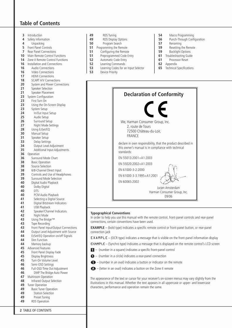
Table of Contents
Typographical ConventionsIn order to help you use this manual with the remote control, front-panel controls and rear-panelconnections, certain conventions have been used.
EXAMPLE – (bold type) indicates a specific remote control or front-panel button, or rear-panel connection jack
EXAMPLE – (OCR type) indicates a message that is visible on the front-panel information display
EXAMPLE – (Synchro type) indicates a message that is displayed on the remote control’s LCD screen
1 – (number in a square) indicates a specific front-panel control
� – (number in a circle) indicates a rear-panel connection
0 – (number in an oval) indicates a button or indicator on the remote
A – (letter in an oval) indicates a button on the Zone II remote
49 RDS Tuning49 RDS Display Options50 Program Search51 Programming the Remote51 Configuring the Remote51 Preprogrammed Code Entry52 Automatic Code Entry52 Learning Commands53 Learning Codes for an Input Selector53 Device Priority
54 Macro Programming56 Punch-Through Configuration57 Renaming59 Resetting the Remote59 Backlight Options61 Troubleshooting Guide61 Processor Reset62 Appendix65 Technical Specifications
Declaration of Conformity
We, Harman Consumer Group, Inc.2, route de Tours72500 Château-du-Loir,FRANCE
declare in own responsibility, that the product described inthis owner’s manual is in compliance with technicalstandards:
EN 55013:2001+A1:2003
EN 55020:2002+A1:2003
EN 61000-3-2:2000
EN 61000-3-3.1995+A1:2001
EN 60065:2002
Jurjen AmsterdamHarman Consumer Group, Inc.
09/06
The appearance of the text or cursor for your receiver’s on-screen menus may vary slightly from theillustrations in this manual. Whether the text appears in all uppercase or upper- and lowercasecharacters, performance and operation remain the same.
30362_AVR445_ENG 20/11/06 14:56 Side 2
INTRODUCTION 3
ENG
LISH
Introduction
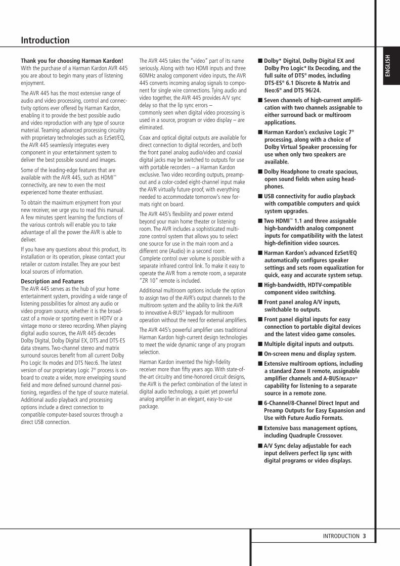
Thank you for choosing Harman Kardon! With the purchase of a Harman Kardon AVR 445you are about to begin many years of listeningenjoyment.
The AVR 445 has the most extensive range ofaudio and video processing, control and connec-tivity options ever offered by Harman Kardon,enabling it to provide the best possible audioand video reproduction with any type of sourcematerial. Teaming advanced processing circuitrywith proprietary technologies such as EzSet/EQ,the AVR 445 seamlessly integrates everycomponent in your entertainment system todeliver the best possible sound and images.
Some of the leading-edge features that areavailable with the AVR 445, such as HDMI™
connectivity, are new to even the mostexperienced home theater enthusiast.
To obtain the maximum enjoyment from yournew receiver, we urge you to read this manual.A few minutes spent learning the functions ofthe various controls will enable you to takeadvantage of all the power the AVR is able todeliver.
If you have any questions about this product, itsinstallation or its operation, please contact yourretailer or custom installer. They are your bestlocal sources of information.
Description and FeaturesThe AVR 445 serves as the hub of your homeentertainment system, providing a wide range oflistening possibilities for almost any audio orvideo program source, whether it is the broad-cast of a movie or sporting event in HDTV or avintage mono or stereo recording. When playingdigital audio sources, the AVR 445 decodesDolby Digital, Dolby Digital EX, DTS and DTS-ESdata streams. Two-channel stereo and matrixsurround sources benefit from all current DolbyPro Logic IIx modes and DTS Neo:6. The latestversion of our proprietary Logic 7® process is on-board to create a wider, more enveloping soundfield and more defined surround channel posi-tioning, regardless of the type of source material.Additional audio playback and processingoptions include a direct connection tocompatible computer-based sources through adirect USB connection.
The AVR 445 takes the “video” part of its nameseriously. Along with two HDMI inputs and three60MHz analog component video inputs, the AVR445 converts incoming analog signals to compo-nent for single wire connections. Tying audio andvideo together, the AVR 445 provides A/V syncdelay so that the lip sync errors – commonly seen when digital video processing isused in a source, program or video display – areeliminated.
Coax and optical digital outputs are available fordirect connection to digital recorders, and boththe front panel analog audio/video and coaxialdigital jacks may be switched to outputs for usewith portable recorders – a Harman Kardonexclusive. Two video recording outputs, preamp-out and a color-coded eight-channel input makethe AVR virtually future-proof, with everythingneeded to accommodate tomorrow’s new for-mats right on board.
The AVR 445’s flexibility and power extendbeyond your main home theater or listeningroom. The AVR includes a sophisticated multi-zone control system that allows you to selectone source for use in the main room and adifferent one (Audio) in a second room.Complete control over volume is possible with aseparate infrared control link. To make it easy tooperate the AVR from a remote room, a separate“ZR 10” remote is included.
Additional multiroom options include the optionto assign two of the AVR’s output channels to themultiroom system and the ability to link the AVRto innovative A-BUS® keypads for multiroomoperation without the need for external amplifiers.
The AVR 445’s powerful amplifier uses traditionalHarman Kardon high-current design technologiesto meet the wide dynamic range of any programselection.
Harman Kardon invented the high-fidelityreceiver more than fifty years ago. With state-of-the-art circuitry and time-honored circuit designs,the AVR is the perfect combination of the latest indigital audio technology, a quiet yet powerfulanalog amplifier in an elegant, easy-to-usepackage.
■ Dolby* Digital, Dolby Digital EX andDolby Pro Logic* IIx Decoding, and thefull suite of DTS® modes, including DTS-ES® 6.1 Discrete & Matrix andNeo:6® and DTS 96/24.
■ Seven channels of high-current amplifi-cation with two channels assignable toeither surround back or multiroomapplications.
■ Harman Kardon’s exclusive Logic 7®
processing, along with a choice ofDolby Virtual Speaker processing foruse when only two speakers areavailable.
■ Dolby Headphone to create spacious,open sound fields when using head-phones.
■ USB connectivity for audio playbackwith compatible computers and quicksystem upgrades.
■ Two HDMI™ 1.1 and three assignablehigh-bandwidth analog componentinputs for compatibility with the latesthigh-definition video sources.
■ Harman Kardon’s advanced EzSet/EQautomatically configures speakersettings and sets room equalization forquick, easy and accurate system setup.
■ High-bandwidth, HDTV-compatiblecomponent video switching.
■ Front panel analog A/V inputs,switchable to outputs.
■ Front panel digital inputs for easyconnection to portable digital devicesand the latest video game consoles.
■ Multiple digital inputs and outputs.
■ On-screen menu and display system.
■ Extensive multiroom options, includinga standard Zone II remote, assignableamplifier channels and A-BUS/READY®
capability for listening to a separatesource in a remote zone.
■ 6-Channel/8-Channel Direct Input andPreamp Outputs for Easy Expansion andUse with Future Audio Formats.
■ Extensive bass management options,including Quadruple Crossover.
■ A/V Sync delay adjustable for eachinput delivers perfect lip sync withdigital programs or video displays.
30362_AVR445_ENG 20/11/06 14:56 Side 3
4 INTRODUCTION / SAFETY INFORMATION
Introduction / Safety Information
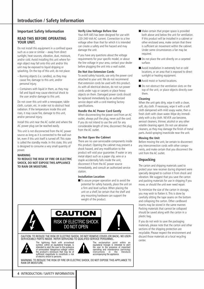
Important Safety Information
READ THIS BEFORE OPERATINGYOUR UNIT.
Do not install this equipment in a confined spacesuch as a case or similar – away from direct sunlight, heat sources, vibration, dust, moisture,and/or cold. Avoid installing this unit where for-eign object may fall onto this unit and/or thisunit may be exposed to liquid dripping orsplashing. On the top of this unit, do not place:
– Burning objects (i.e. candles), as they maycause fire, damage to this unit, and/orpersonal injury.
– Containers with liquid in them, as they mayfall and liquid may cause electrical shock tothe user and/or damage to this unit.
Do not cover this unit with a newspaper, table-cloth, curtain, etc. in order not to obstruct heatradiation. If the temperature inside this unitrises, it may cause fire, damage to this unit,and/or personal injury.
Install this unit near the AC outlet and where theAC power plug can be reached easily.
This unit is not disconnected from the AC powersource as long as it is connected to the wall out-let, even if this unit itself is turned off. This stateis called the standby mode. In this state, this unitis designed to consume a very small quantity ofpower.
WARNINGTO REDUCE THE RISK OF FIRE OR ELECTRICSHOCK, DO NOT EXPOSE THIS APPLIANCETO RAIN OR MOISTURE.
Verify Line Voltage Before UseYour AVR 445 has been designed for use with220-240-Volt AC current. Connection to a linevoltage other than that for which it is intendedcan create a safety and fire hazard and maydamage the unit.
If you have any questions about the voltagerequirements for your specific model, or aboutthe line voltage in your area, contact your dealerbefore plugging the unit into a wall outlet.
Do Not Use Extension CordsTo avoid safety hazards, use only the power cordattached to your unit. We do not recommendthat extension cords be used with this product.As with all electrical devices, do not run powercords under rugs or carpets or place heavyobjects on them. Damaged power cords shouldbe replaced immediately by an authorizedservice depot with a cord meeting factoryspecifications.
Handle the AC Power Cord GentlyWhen disconnecting the power cord from an ACoutlet, always pull the plug, never pull the cord.If you do not intend to use the unit for anyconsiderable length of time, disconnect the plugfrom the AC outlet.
Do Not Open the CabinetThere are no user-serviceable components insidethis product. Opening the cabinet may present ashock hazard, and any modification to theproduct will void your guarantee. If water or anymetal object such as a paper clip, wire or astaple accidentally falls inside the unit,disconnect it from the AC power sourceimmediately, and consult an authorized servicestation.
Installation Location■ To assure proper operation and to avoid the
potential for safety hazards, place the unit ona firm and level surface. When placing theunit on a shelf, be certain that the shelf andany mounting hardware can support theweight of the product.
■ Make certain that proper space is providedboth above and below the unit for ventilation.If this product will be installed in a cabinet orother enclosed area, make certain that thereis sufficient air movement within the cabinet.Under some circumstances a fan may berequired.
■ Do not place the unit directly on a carpetedsurface.
■ Avoid installation in extremely hot or coldlocations, or an area that is exposed to directsunlight or heating equipment.
■ Avoid moist or humid locations.
■ Do not obstruct the ventilation slots on thetop of the unit, or place objects directly overthem.
CleaningWhen the unit gets dirty, wipe it with a clean,soft, dry cloth. If necessary, wipe it with a softcloth dampened with mild soapy water, then afresh cloth with clean water. Wipe dry immedi-ately with a dry cloth. NEVER use benzene,aerosol cleaners, thinner, alcohol or any othervolatile cleaning agent. Do not use abrasivecleaners, as they may damage the finish of metalparts. Avoid spraying insecticide near the unit.
Moving the UnitBefore moving the unit, be certain to disconnectany interconnection cords with other compo-nents, and make certain that you disconnect theunit from the AC outlet.
Unpacking
The carton and shipping materials used toprotect your new receiver during shipment werespecially designed to cushion it from shock andvibration. We suggest that you save the cartonand packing materials for use in shipping if youmove, or should the unit ever need repair.
To minimize the size of the carton in storage,you may wish to flatten it. This is done bycarefully slitting the tape seams on the bottomand collapsing the carton. Other cardboardinserts may be stored in the same manner.Packing materials that cannot be collapsedshould be saved along with the carton in aplastic bag.
If you do not wish to save the packagingmaterials, please note that the carton and othersections of the shipping protection arerecyclable. Please respect the environment anddiscard those materials at a local recyclingcenter.
30362_AVR445_ENG 20/11/06 14:56 Side 4
FRONT PANEL CONTROLS 5
ENG
LISH
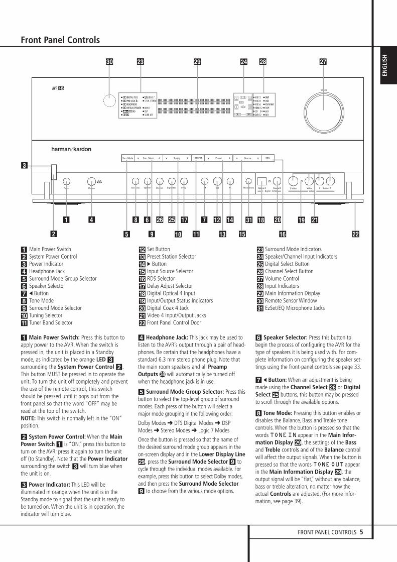
1 Main Power Switch: Press this button toapply power to the AVR. When the switch ispressed in, the unit is placed in a Standbymode, as indicated by the orange LED 3surrounding the System Power Control 2.This button MUST be pressed in to operate theunit. To turn the unit off completely and preventthe use of the remote control, this switchshould be pressed until it pops out from thefront panel so that the word “OFF” may be read at the top of the switch.NOTE: This switch is normally left in the “ON”position.
2 System Power Control: When the MainPower Switch 1 is “ON,” press this button toturn on the AVR; press it again to turn the unitoff (to Standby). Note that the Power Indicatorsurrounding the switch 3 will turn blue whenthe unit is on.
3 Power Indicator: This LED will be illuminated in orange when the unit is in theStandby mode to signal that the unit is ready tobe turned on. When the unit is in operation, theindicator will turn blue.
4 Headphone Jack: This jack may be used tolisten to the AVR’s output through a pair of head-phones. Be certain that the headphones have astandard 6.3 mm stereo phone plug. Note thatthe main room speakers and all PreampOutputs � will automatically be turned offwhen the headphone jack is in use.
5 Surround Mode Group Selector: Press thisbutton to select the top-level group of surroundmodes. Each press of the button will select amajor mode grouping in the following order:
Dolby Modes ➜ DTS Digital Modes ➜ DSPModes ➜ Stereo Modes ➜ Logic 7 Modes
Once the button is pressed so that the name ofthe desired surround mode group appears in theon-screen display and in the Lower Display Line˜, press the Surround Mode Selector 9 tocycle through the individual modes available. Forexample, press this button to select Dolby modes,and then press the Surround Mode Selector9 to choose from the various mode options.
6 Speaker Selector: Press this button tobegin the process of configuring the AVR for thetype of speakers it is being used with. For com-plete information on configuring the speaker set-tings using the front-panel controls see page 33.
7 ‹ Button: When an adjustment is beingmade using the Channel Select Ù or DigitalSelect Û buttons, this button may be pressedto scroll through the available options.
8 Tone Mode: Pressing this button enables ordisables the Balance, Bass and Treble tone controls. When the button is pressed so that thewords TONEIN appear in the Main Infor-mation Display ˜, the settings of the Bassand Treble controls and of the Balance controlwill affect the output signals. When the button ispressed so that the words TONEOUT appearin the Main Information Display ˜, theoutput signal will be “flat,” without any balance,bass or treble alteration, no matter how theactual Controls are adjusted. (For more infor-mation, see page 39).
Front Panel Controls
1234 5 67 8 9 )!
@ # $ % ^ & * ( Ó Ô
Ò Ú Û Ù ı ˆ ˜ ¯ ˘
Main Power SwitchSystem Power ControlPower IndicatorHeadphone JackSurround Mode Group SelectorSpeaker Selector‹ ButtonTone ModeSurround Mode SelectorTuning SelectorTuner Band Selector
Set ButtonPreset Station Selector› ButtonInput Source SelectorRDS SelectorDelay Adjust SelectorDigital Optical 4 InputInput/Output Status IndicatorsDigital Coax 4 JackVideo 4 Input/Output JacksFront Panel Control Door
Surround Mode IndicatorsSpeaker/Channel Input IndicatorsDigital Select ButtonChannel Select ButtonVolume ControlInput IndicatorsMain Information DisplayRemote Sensor WindowEzSet/EQ Microphone Jacks
AVR 445
4 9 A C E L
R N�M
8 F
� 3 5 P O G 6 DB � H I KJ
Q�
1
7
2
30362_AVR445_ENG 20/11/06 14:56 Side 5
6 FRONT PANEL CONTROLS
Front Panel Controls
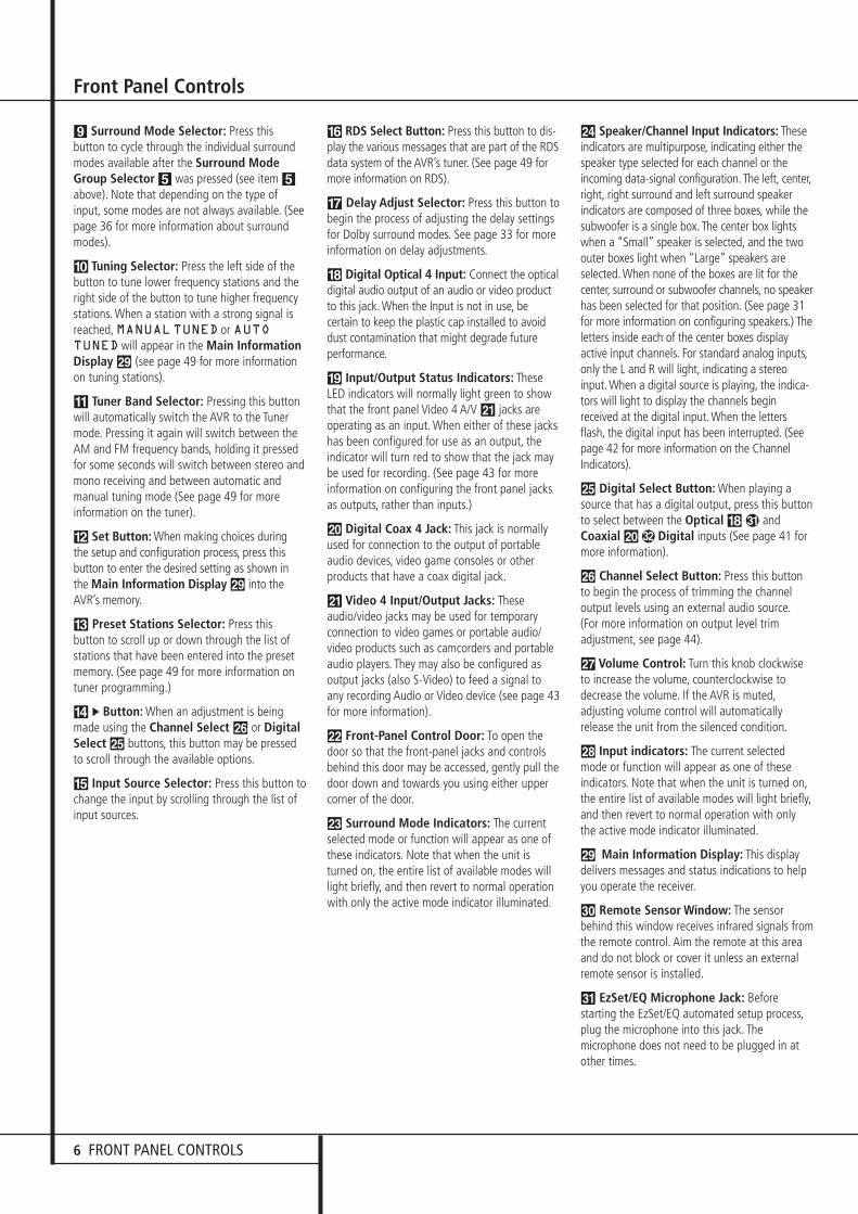
9 Surround Mode Selector: Press thisbutton to cycle through the individual surroundmodes available after the Surround ModeGroup Selector 5 was pressed (see item 5above). Note that depending on the type ofinput, some modes are not always available. (Seepage 36 for more information about surroundmodes).
) Tuning Selector: Press the left side of thebutton to tune lower frequency stations and theright side of the button to tune higher frequencystations. When a station with a strong signal isreached, MANUALTUNED or AUTOTUNEDwill appear in the Main InformationDisplay ˜ (see page 49 for more informationon tuning stations).
! Tuner Band Selector: Pressing this buttonwill automatically switch the AVR to the Tunermode. Pressing it again will switch between theAM and FM frequency bands, holding it pressedfor some seconds will switch between stereo andmono receiving and between automatic andmanual tuning mode (See page 49 for moreinformation on the tuner).
@ Set Button: When making choices during the setup and configuration process, press thisbutton to enter the desired setting as shown inthe Main Information Display ˜ into theAVR’s memory.
# Preset Stations Selector: Press thisbutton to scroll up or down through the list ofstations that have been entered into the presetmemory. (See page 49 for more information ontuner programming.)
$ › Button: When an adjustment is beingmade using the Channel Select Ù or DigitalSelect Û buttons, this button may be pressedto scroll through the available options.
% Input Source Selector: Press this button tochange the input by scrolling through the list ofinput sources.
^ RDS Select Button: Press this button to dis-play the various messages that are part of the RDSdata system of the AVR’s tuner. (See page 49 formore information on RDS).
& Delay Adjust Selector: Press this button tobegin the process of adjusting the delay settingsfor Dolby surround modes. See page 33 for moreinformation on delay adjustments.
* Digital Optical 4 Input: Connect the opticaldigital audio output of an audio or video productto this jack. When the Input is not in use, be certain to keep the plastic cap installed to avoiddust contamination that might degrade future performance.
( Input/Output Status Indicators: TheseLED indicators will normally light green to showthat the front panel Video 4 A/V Ô jacks areoperating as an input. When either of these jackshas been configured for use as an output, theindicator will turn red to show that the jack maybe used for recording. (See page 43 for moreinformation on configuring the front panel jacksas outputs, rather than inputs.)
Ó Digital Coax 4 Jack: This jack is normallyused for connection to the output of portableaudio devices, video game consoles or otherproducts that have a coax digital jack.
Ô Video 4 Input/Output Jacks: Theseaudio/video jacks may be used for temporaryconnection to video games or portable audio/video products such as camcorders and portableaudio players. They may also be configured asoutput jacks (also S-Video) to feed a signal toany recording Audio or Video device (see page 43for more information).
Front-Panel Control Door: To open thedoor so that the front-panel jacks and controlsbehind this door may be accessed, gently pull thedoor down and towards you using either uppercorner of the door.
Ò Surround Mode Indicators: The currentselected mode or function will appear as one ofthese indicators. Note that when the unit isturned on, the entire list of available modes willlight briefly, and then revert to normal operationwith only the active mode indicator illuminated.
Ú Speaker/Channel Input Indicators: Theseindicators are multipurpose, indicating either thespeaker type selected for each channel or theincoming data-signal configuration. The left, center,right, right surround and left surround speakerindicators are composed of three boxes, while thesubwoofer is a single box. The center box lightswhen a “Small” speaker is selected, and the twoouter boxes light when “Large” speakers areselected. When none of the boxes are lit for thecenter, surround or subwoofer channels, no speakerhas been selected for that position. (See page 31for more information on configuring speakers.) Theletters inside each of the center boxes displayactive input channels. For standard analog inputs,only the L and R will light, indicating a stereoinput. When a digital source is playing, the indica-tors will light to display the channels beginreceived at the digital input. When the lettersflash, the digital input has been interrupted. (Seepage 42 for more information on the ChannelIndicators).
Û Digital Select Button: When playing asource that has a digital output, press this buttonto select between the Optical *� andCoaxial Ó� Digital inputs (See page 41 formore information).
Ù Channel Select Button: Press this buttonto begin the process of trimming the channeloutput levels using an external audio source.(For more information on output level trimadjustment, see page 44).
ı Volume Control: Turn this knob clockwiseto increase the volume, counterclockwise todecrease the volume. If the AVR is muted,adjusting volume control will automaticallyrelease the unit from the silenced condition.
ˆ Input indicators: The current selectedmode or function will appear as one of theseindicators. Note that when the unit is turned on,the entire list of available modes will light briefly,and then revert to normal operation with onlythe active mode indicator illuminated.
˜ Main Information Display: This displaydelivers messages and status indications to helpyou operate the receiver.
¯ Remote Sensor Window: The sensorbehind this window receives infrared signals fromthe remote control. Aim the remote at this areaand do not block or cover it unless an externalremote sensor is installed.
˘ EzSet/EQ Microphone Jack: Beforestarting the EzSet/EQ automated setup process,plug the microphone into this jack. Themicrophone does not need to be plugged in atother times.
30362_AVR445_ENG 20/11/06 14:56 Side 6
REAR PANEL CONNECTIONS 7
ENG
LISH
Rear Panel Connections
������� �������
����������� !��"#
$%&�' ) * + , - .
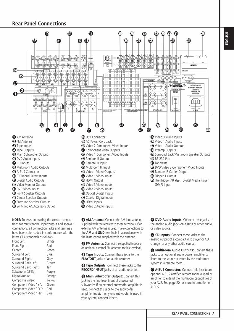
AM AntennaFM AntennaTape InputsTape OutputsMain Subwoofer OutputDVD Audio InputsCD InputsMultiroom Audio OutputsA-BUS Connector8-Channel Direct InputsDigital Audio OutputsVideo Monitor OutputsDVD Video InputsFront Speaker OutputsCenter Speaker OutputsSurround Speaker OutputsSwitched AC Accessory Outlet
USB ConnectorAC Power Cord JackVideo 2 Component Video InputsComponent Video OutputsVideo 1 Component Video InputsRemote IR OutputRemote IR InputMultiroom IR InputVideo 1 Video OutputsVideo 1 Video InputsHDMI OutputVideo 3 Video InputsVideo 2 Video InputsOptical Digital InputsCoaxial Digital InputsHDMI InputsVideo 2 Audio Inputs
Video 3 Audio InputsVideo 1 Audio InputsVideo 1 Audio OutputsPreamp OutputsSurround Back/Multiroom Speaker OutputsRS-232 PortFan VentsDVD/Video 3 Component Video InputsRemote IR Carrier OutputTrigger 1 OutputThe Bridge Digital Media Player(DMP) Input
The Bridge TM
NOTE: To assist in making the correct connec-tions for multichannel input/output and speakerconnections, all connection jacks and terminalshave been color coded in conformance with thelatest CEA standards as follows:Front Left: WhiteFront Right: RedCenter: GreenSurround Left: BlueSurround Right: GraySurround Back Left: BrownSurround Back Right: TanSubwoofer (LFE): PurpleDigital Audio: OrangeComposite Video: YellowComponent Video “Y”: GreenComponent Video “Pr”: RedComponent Video “Pb”: Blue
� AM Antenna: Connect the AM loop antennasupplied with the receiver to these terminals. If anexternal AM antenna is used, make connections tothe AM and GND terminals in accordance withthe instructions supplied with the antenna.
� FM Antenna: Connect the supplied indoor oran optional external FM antenna to this terminal.
� Tape Inputs: Connect these jacks to thePLAY/OUT jacks of an audio recorder.
� Tape Outputs: Connect these jacks to theRECORD/INPUT jacks of an audio recorder.
� Main Subwoofer Output: Connect thisjack to the line-level input of a poweredsubwoofer. If an external subwoofer amplifier isused, connect this jack to the subwooferamplifier input. If only one subwoofer is used inyour system, connect it here.
DVD Audio Inputs: Connect these jacks tothe analog audio jacks on a DVD or other audioor video source.
CD Inputs: Connect these jacks to the analog output of a compact disc player or CDchanger or any other audio source.
� Multiroom Audio Outputs: Connect thesejacks to an optional audio power amplifier tolisten to the source selected by the multiroomsystem in a remote room.
� A-BUS Connector: Connect this jack to anoptional A-BUS-certified remote room keypad oramplifier to extend the multiroom capabilities ofyour AVR. See page 20 for more information onA-BUS.
30362_AVR445_ENG 20/11/06 14:56 Side 7
8 REAR PANEL CONNECTIONS
Rear Panel Connections
8-Channel Direct Inputs: These jacks areused for connection to source devices such asDVD-Audio or SACD players with discrete analogoutputs. Depending on the source device in use,all eight jacks may be used, though in manycases only connections to the front left/right,center, surround left/right and LFE (subwooferinput) jacks will be used for standard 5.1 audiosignals.
� Digital Audio Outputs: Connect thesejacks to the matching digital input connector ona digital recorder such as a CD-R or MiniDiscrecorder.
� Video Monitor Outputs: Connect this jackto the composite and/or S-Video input of a TVmonitor or video projector to view the on-screenmenus and the output of any standard Video orS-Video source selected by the receiver’s videoswitcher.
� DVD Video Inputs: Connect these jacks tothe composite or S-Video output jacks on a DVDplayer or other video source.
� Front Speaker Outputs: Connect theseoutputs to the matching + or – terminals on yourleft and right speakers. In conformance with thenew CEA color code specification, the White ter-minal is the positive, or "+" terminal that shouldbe connected to the red (+) terminal on FrontLeft speaker with the older color coding, whilethe Red terminal is the positive, or "+" terminalthat should be connected to the red (+) terminalon Front Right speaker. Connect the black (–)terminals on the AVR to the black (–) terminalson the speakers. See page 16 for moreinformation on speaker polarity.
� Center Speaker Outputs: Connect theseoutputs to the matching + and – terminals onyour center channel speaker. In conformance withthe new CEA color code specification, the GreenTerminal is the positive, or "+" terminal thatshould be connected to the red (+) terminal onspeakers with the older color coding. Connectthe black (–) terminal on the AVR to the blacknegative (–) terminal on your speaker. (See page16 for more information on speaker polarity.)
� Surround Speaker Outputs: Connectthese outputs to the matching + and – terminalson your surround channel speakers. In confor-mance with the new CEA color code specifica-tion, the Blue terminal is the positive, or "+"terminal that should be connected to the red (+)terminal on the Surround Left speaker with oldercolor coding, while the Gray terminal should beconnected to the red (+) terminal on theSurround Right speaker with the older colorcoding. Connect the black (–) terminal on theAVR to the matching black negative (–) terminalsfor each surround speaker. (See page 16 for moreinformation on speaker polarity.)
� Switched AC Accessory Outlet: This outletmay be used to power any device that you wishto have turn on when the AVR is turned on withthe System Power Control switch 2.
� USB Connector: Connect a cable with aUSB “Mini B” connector to the AVR and theother end to a compatible computer runningWindows® 2000, Windows® XP or higher withthe latest service packs installed, to use this portto listen to audio from the computer through theAVR 445. This connection is also used to connecta compatible computer to the AVR for firmwareupgrades, when available. See page 41 for moreinformation on playback of computer audio withthe AVR. Instructions for upgrades will accompa-ny the upgrade file download package.
� AC Power Cord Jack: Connect the ACpower cord to this jack when the installation iscomplete. To ensure safe operation, use only thepower cord supplied with the unit. If a replace-ment is required it must be of the same type andcapacity.
� Component Video 2 Inputs: These inputsmay be used with any video source deviceequipped with analog Y/Pr/Pb or RGB componentvideo outputs. The factory default is for thesejacks to be a linked to the Video 2 input, but youmay change the setting at any time through theIN/OUTSETUPmenu. See page 16 formore information on configuring the componentvideo inputs.
� Monitor Component Video Outputs:Connect these outputs to the component videoinputs of a video projector or monitor. When asource connected to one of the twoComponent Video Inputs �� is selected thesignal will be sent to these jacks.
� Component Video 1 Inputs: These inputsmay be used with any source device equippedwith analog Y/Pr/Pb or RGB component videooutputs. The factory default is for these jacks tobe a linked to the Video 1 input, but you maychange the setting at any time through theIN/OUTSETUPmenu. See page 16 formore information on configuring the componentvideo inputs.
Note: All component inputs/outputs can be usedfor RGB signals too, in the same way asdescribed for the Y/Pr/Pb signals, then connectedto the jacks with the corresponding color.RGB connection is not possible if the source out-puts a separate sync signal.
� Remote IR Output: This connection permitsthe IR sensor in the receiver to serve otherremote controlled devices. Connect this jack tothe “IR IN” jack on Harman Kardon or othercompatible equipment.
� Remote IR Input: If the AVR’s front-panelIR sensor is blocked due to cabinet doors orother obstructions, an external IR sensor may beused. Connect the output of the sensor to thisjack.
� Multiroom IR Input: Connect the output of anIR sensor in a remote room to this jack to operatethe AVR’s multiroom control system.
� Video 1 Video Outputs: Connect thesejacks to the RECORD/INPUT composite or S-Video jack on a VCR.
� Video 1 Video Inputs: Connect these jacksto the PLAY/OUT composite or S-Video jacks ona VCR or other video source.
� HDMI Output: Connect this jack to theHDMI input on a compatible HDMI-equippedvideo display.
Video 3 Video Inputs: Connect these jacksto the PLAY/OUT composite or S-Video jacks onany video source.
! Video 2 Video Inputs: Connect these jacksto the PLAY/OUT composite or S-Video jacks ona second VCR or other video source.
� Optical Digital Inputs: Connect the optical digital output from a DVD player, HDTVreceiver, LD player, MD player or CD player tothese jacks. The signal may be either a DolbyDigital signal, a DTS signal, a 2 channel MPEG 1signal or a standard PCM digital source.
30362_AVR445_ENG 20/11/06 14:56 Side 8
REAR PANEL CONNECTIONS 9
ENG
LISH� Coaxial Digital Inputs: Connect the coax
digital output from a DVD player, HDTV receiver,LD player, MD player or CD player to these jacks.The signal may be either a Dolby Digital signal,DTS signal, a 2 channel MPEG 1 signal or astandard PCM digital source. Do not connect theRF digital output of an LD player to these jacks.
" HDMI Inputs: Connect the HDMI output ofvideo sources such as a DVD player, set-top boxor HDTV tuner to either of these jacks.
# Video 2 Audio Inputs: Connect these jacksto the PLAY/OUT audio jacks on a second VCRor other audio or video source.
$ Video 3 Audio Inputs: Connect these jacksto the PLAY/OUT audio jacks on any audio orvideo source.
% Video 1 Audio Inputs: Connect these jacksto the PLAY/OUT audio jacks on a VCR or otheraudio or video source.
& Video 1 Audio Outputs: Connect thesejacks to the RECORD/INPUT audio jacks on a VCR or any other Audio recorder.
� Preamp Outputs: Connect these jacks to anoptional, external power amplifier forapplications where higher power is desired.
' Surround Back/Multiroom SpeakerOutputs: These speaker terminals are normallyused to power the surround back left/surroundback right speakers in a 7.1 channel system.However, they may also be used to power thespeakers in a second zone, which will receive theoutput selected for a multiroom system.To change the output fed to these terminals fromthe default of the Surround Back speakers to theMultiroom Output, you must change a setting inthe Multiroom Menu of the OSD system. Seepage 47 for more information on configuring thisspeaker output. In normal surround system use,the brown and black terminals are the surroundback left channel positive (+) and negative (–)connections and the tan and black terminals arethe surround back right positive (+) and negative(–) terminals.For multiroom use, connect the brown and blackSBL terminals to the red and black connectionson the left remote zone speaker and connect thetan and black SBR terminals to the red and blackterminals on the right remote zone speaker.
) RS-232 Port: This jack may be used tocontrol the AVR 445 over a bi-directional RS-232serial control link to a compatible computer orprogrammable remote control system. Due to thecomplexity of programming RS-232 commandswe strongly recommend that connections to thisport for control purposes be made by a trainedand qualified technician. This jack may also linkto a compatible computer to upgrade thesoftware and operating system of the AVR 445when appropriate upgrades are available.
* Fan Vents: These ventilation holes are theoutput of the AVR’s airflow system. To ensureproper operation of the unit and to avoidpossible damage to delicate surfaces, makecertain that these holes are not blocked and thatthere is at least three inches of open spacebetween the vent holes and any wooden orfabric surface.
+ DVD/Video 3 Component Video Inputs:These inputs may be used with any source deviceequipped with analog Y/Pr/Pb or RGB componentvideo outputs. The factory default is for thesejacks to be a linked to the DVD input, but youmay change the setting at any time through theIN/OUTSETUPmenu. See page 17 formore information on configuring the componentvideo inputs.
, Remote IR Carrier Output: The output ofthis jack is the full signal received at theRemote Sensor Window ¯ or input throughthe Remote IR Input � including the carrierfrequency that is removed from signals at theRemote IR Output �. Use this output toextend IR remote signals to the input ofcompatible products by direct connection orthrough the use of optional, external IR“blasters”. If you are in doubt as to which of thetwo IR Output jacks to use, we recommend thatyou consult with your dealer or installer, or checkwith the manufacturer of the external equipmentyou wish to control.
- Trigger 1 Output: Connect this jack to the“Trigger In” jack of an optional externalcomponent such as an audio power amplifierthat you want to be controlled to mirror thepower state of the AVR 445. When thisconnection is used, the AVR 445 will automati-cally send a low-voltage signal to the connecteddevice that turns it on when the AVR 445 is onand off when the AVR 445 is placed in theStandby Mode. The connected component mustrespond to 6-volt presence as the control signal.
. Digital Media Player (DMP)Connector: With the AVR 445 turned off,connect one end of the optional Harman Kardon
to this proprietary connector, and theother to your compatible Apple iPod. When theDigital Media Player source is selected, you mayview your iPod’s control and navigationmessages on your video display (if one isconnected to one of the Video MonitorOutputs �), and in the Upper and LowerDisplay Lines ˜. You may navigate the iPodand select tracks for playback using the ⁄¤‹ › Buttons EF, the Set ButtonFQ and Transport Controls PP onyour AVR remote. See page 43 for moreinformation.
Rear Panel Connections
30362_AVR445_ENG 20/11/06 14:56 Side 9

10 MAIN REMOTE CONTROL FUNCTIONS
0
1
2
3
4
5
6
7
8
9
A
B
C
D
E
F
G
H
I
J
K
L
M
N
O
P
Q
�
�
�
�
�
�
�
�
�
�
�
�
�
�
Main Remote Control Functions
Power Off ButtonIR Transmitter WindowLCD Information DisplayPower On ButtonInput SelectorsAVR SelectorAM/FM Tuner Select6-Channel/8-Channel Direct InputTest ButtonSleep ButtonSurround Mode SelectorNight ModeChannel Select ButtonDim ButtonNavigation ButtonSet ButtonDigital SelectNumeric KeysTuner ModeDirect ButtonTuning Up/DownOSD ButtonDolby Mode Select ButtonDTS Digital Mode SelectorLogic 7 Mode Select ButtonTransport ControlsLight ButtonSkip Up/Down ButtonsStereo Mode Select ButtonDTS Neo:6 Mode SelectMacro ButtonsDisc Skip ButtonPreset Up/DownClear ButtonMemory ButtonDelay/Prev. Ch.Program ButtonSpeaker SelectMultiroomVolume Up/DownEzSet/EQ On/Off ButtonChannel Up/Down SelectorMuteTone Control Button
NOTE: The function names shown here are eachbutton’s feature when used with the AVR. Mostbuttons have additional functions when usedwith other devices.
The jack on the upper right side of the remote isreserved for future use. Do not remove the plugprovided or connect any device to the jack.
4
E
�
�
�
�
P
I
�
N
7
H
P
M
3
2
0
5
8A
O
J
�
�
C
GF
�
P
Q�
K
�
9B
L
D
�
6
�
�
1
�
30362_AVR445_ENG 20/11/06 14:56 Side 10

MAIN REMOTE CONTROL FUNCTIONS 11
ENG
LISH
Main Remote Control Functions
IMPORTANT NOTE: The AVR 445’s remote maybe programmed to control up to seven devices,including the AVR. Before using the remote, it isimportant to remember to press the InputSelector button 4 that corresponds to theunit you wish to operate. In addition, the AVR’sremote is shipped from the factory to operate theAVR and most Harman Kardon CD or DVD playersand cassette decks. The remote is also capable ofoperating a wide variety of other products usingthe control codes that are part of the remote orby learning commands from other remotes. Beforeusing the remote with other products, follow theinstructions on pages 51-52 to program the prop-er codes for the products in your system.
It is also important to remember that many ofthe buttons on the remote take on different functions, depending on the product selectedusing the Input Selector Button 4. Thedescriptions shown here primarily detail the func-tions of the remote when it is used to operatethe AVR.
0 Power Off Button: Press this button toplace the AVR or a selected device unit in theStandby mode. Note that when the AVR isswitched off this will turn off the main room functions, but if the Multiroom system is activated,it will continue to function.
1 IR Transmitter Window: Point this windowtowards the AVR when pressing buttons on theremote to make certain that infrared commandsare properly received.
2 LCD Information Display: This two-linescreen displays various information depending onthe commands that have been entered into theremote.
3 Power On Button: Press this button to turnon the power to a device selected by pressing oneof the Input Selectors 4 (except Tape).
4 Input Selectors: Pressing one of thesebuttons will perform three actions at the sametime. First, if the AVR is not turned on, this willpower up the unit. Next, it will select the sourceshown on the button as the input to the AVR.Finally, it will change the remote control so thatit controls the device selected.
The buttons labeled DVD, DMP and HDMI 1 areeach used to select either of two input sources:
• The first press of the DVD Button selects thecomponent connected to the DVD inputs. A sec-ond press of this button selects the componentconnected to the CD inputs.
• The first press of the button labeled DMPselects The Bridge as the input. A second press ofthis button selects the device connected to theTape inputs.
• The first press of the HDMI 1 button selects thedevice that is connected to the HDMI 1 jack.A second press selects the device connected tothe HDMI 2 jack.
In normal operation, the remote will revert tocontrolling the AVR when no button is pressedfor 6 seconds. This allows the remote toautomatically return to control of importantfunctions such as volume, mute and surroundmode selection after you have used the remoteto control another device. If you wish to changethe length of time that the remote operatesanother device, or to have the remote remainactive for control of the other device (such as aDVD player or set-top box) until you manuallyreturn control to the AVR by pressing the AVRSelector 5, follow the instructions on page38.
5 AVR Selector: Pressing this button willswitch the remote so that it will operate the AVR’sfunctions. If the AVR is in the Standby mode, it willalso turn the AVR on.
6 AM/FM Tuner Select: Press this button toselect the AVR’s tuner as the listening choice.Pressing this button when the tuner is in use willselect between the AM and FM bands.
7 6-Channel/8 Channel Direct Input:Press this button to select the device connectedto the 6-Channel Direct Inputs or the 8-Channel Direct Inputs (the input available will depend on the selection 5.1 or6.1/7.1 made in the surround mode setting,see page 26 for more information).
8 Test Tone: Press this button to begin thesequence used to calibrate the AVR’s output levels.(See page 34 for more information on calibratingthe AVR.)
9 Sleep Button: Press this button to placethe unit in the Sleep mode. After the time shownin the display, the AVR will automatically go intothe Standby mode. Each press of the buttonchanges the time until turn-off in the followingorder:
Hold the button pressed for two seconds to turnoff the Sleep mode setting.Note that this button is also used to changechannels on your TV, VCR and Sat receiver whenthe appropriate source is selected, using thedevice Input Selectors 4.
A Surround Mode Selector: Press this but-ton to select any of the HALL, THEATER surroundmodes. Note that depending on the type ofinput, some modes are not always available. (Seepage 36 for more information about surroundmodes.) Note that this button is also used totune channels on your TV, VCR and Sat receiverwhen the appropriate source is selected usingthe device Input Selector 4.
B Night Mode: Press this button to activatethe Night mode. This mode is available only withDolby Digital encoded sources, and it preservesdialog (center channel) intelligibilty at low vol-ume levels (See page 27 for more information).
C Channel Select Button: This button isused to start the process of setting the AVR’soutput levels with an external source. Once thisbutton is pressed, use the ⁄/¤ buttons E toselect the channel being adjusted, then press theSet button F, followed by the ⁄/¤ buttonsE again, to change the level setting. (See page34 for more information.)
D Dim Button: Press this button to activatethe Dimmer function, which reduces the bright-ness of the front-panel display, or turns it offentirely. Press the button once to change thedisplay to reduce the brightness by 50%, andpress it again within five seconds and the maindisplay will go completely dark. Note that thissetting is temporary; regardless of any changes,the display will always return to full brightnesswhen the AVR is turned on. The blue illuminationaround the Standby/On Button 1 will alwaysremain at full brightness regardless of the settingto remind you that the AVR is still turned on. Theblue accent lighting inside the volume controlwill also remain at full brightness when the panelis at 50%, but go out when the panel lights arefully dimmed.
90min
80min
70min
60min
50min
40min
30min
20min
10min OFF
30362_AVR445_ENG 20/11/06 14:56 Side 11

12 MAIN REMOTE CONTROL FUNCTIONS
E Navigation Button: This single disc-likebutton is used to change or scroll through itemsin the on-screen menus or on the front panel orto make configuration settings such as digitalinputs or delay timing. When changing a setting,first press the button for the function or settingto be changed (e.g., press the Digital SelectButton G to change a digital input) and thenpress one of these buttons to scroll through thelist of options or to increase or decrease a set-ting. The sections in this manual describing theindividual features and functions contain specificinformation on using these buttons for eachapplication.
F Set Button: This button is used to enter settings into the AVR’s memory. It is also used inthe setup procedures for delay time, speakerconfiguration and channel output leveladjustment.
G Digital Select: Press this button to assignone of the digital inputs ��*Ó to a source.(See page 41 for more information on using digital inputs.)
H Numeric Keys: These buttons serve as aten-button numeric keypad to enter tuner presetpositions. They are also used to select channelnumbers when TV, VCR or Sat receiver has beenselected on the remote, or to select tracknumbers on a CD, DVD or LD player, dependingon how the remote has been programmed.
I Tuner Mode: Press this button when thetuner is in use to select between automatictuning and manual tuning. When the button ispressed so MANUAL appears in the MainInformation Display ˜, pressing the Tuningbuttons K) will move the frequency up ordown in single-step increments. When the FMband is in use and AUTO appears in the MainInformation Display ˜, pressing this buttonwill change to monaural reception making evenweek stations audible. (See page 49 for moreinformation.)
J Direct Button: Press this button when thetuner is in use to start the sequence for directentry of a station’s frequency. After pressing thebutton simply press the proper Numeric KeysH to select a station (See page 49 for moreinformation on the tuner).
K Tuning Up/Down: When the tuner is in use,these buttons will tune up or down through theselected frequency band. If the Tuner Modebutton I has been pressed or the Band button! on the front panel was held pressed so thatAUTO appears in the Main InformationDisplay ˜, pressing either of the buttons willcause the tuner to seek the next station withacceptable signal strength for quality reception.When the MANUAL appears in the MainInformation Display ˜, pressing thesebuttons will tune stations in single-stepincrements. (See page 50 for more information.)
L OSD Button: Press this button to activatethe On Screen Display (OSD) system used to setup or adjust the AVR’s parameters.
M Dolby Mode Selector: This button is usedto select one of the available Dolby Surround processing modes. Each press of this button willselect one of the Dolby Pro Logic II modes, Dolby3 Stereo or Dolby Digital. Note that the DolbyDigital mode is only available with a digital inputselected and the other modes only as long as aDolby Digital source is not playing (except Pro Logic II with Dolby Digital 2.0 recordings, seeNote on page 40). See page 27 for the availableDolby surround mode options.
N DTS Digital Mode Selector: When a DTSsource is in use the AVR will select theappropriate mode automatically and no othermode will be available. Pressing this button willdisplay the mode currently selected by the AVR´sdecoder, depending on the surround materialplayed and the speaker setting (see item 6,page 5). When a DTS source is not in use, thisbutton has no function. (See page 27, 32 for theavailable DTS options.)
O Logic 7 Selector: Press this button toselect one of the available Logic 7 surroundmodes. (See page 36 for the available Logic 7options.)
P Transport Control Buttons: These buttonsdo not have any functions for the AVR, but theymay be programmed for the forward/reverse playoperation of a wide variety of CD or DVD players,and audio or video- cassette recorders. (See page51 for more information on programming theremote.)
Q Light Button: Press this button to activatethe remote’s built-in backlight for better legibilityof the buttons in a darkened room.
� Skip Up/Down Buttons: These buttons donot have a direct function with the AVR, butwhen used with a compatibly programmed CD orDVD player/changer they will change the trackson the disc currently being played.
� Stereo Mode Selector: Press this buttonto select a stereo playback mode. When thebutton is pressed so that DSPSURROFFappears in the Main Information Display ˜,the AVR will operate in a bypass mode with truefully analog, two-channel left/right stereo modewith no surround processing or bassmanagement as opposed to other modes wheredigital processing is used. When the button ispressed so that SURROUNDOFF appears inthe Main Information Display ˜, you mayenjoy a two-channel presentation of the soundalong with the benefits of bass management.When the button is pressed so that 5 CHSTEREO or 7 CHSTEREO appears, thestereo signal is routed to all five speakers, ifinstalled. (See page 40 for more information onstereo playback modes).
� DTS Neo:6 Mode Selector: Pressing thisselector button cycles the AVR through the various DTS Neo:6 modes, which extract a five-or seven-channel surround field from two-chan-nel program material (from PCM source oranalog input signal). The first press selects thelast DTS Neo:6 surround mode that was in use,and each subsequent press selects the nextmode in the following order:
� Macro Buttons: Press these buttons tostore or recall a “Macro”, which is a pre-pro-grammed sequence of commands stored in theremote. (See page 54 for more information onstoring and recalling macros.)
� Disc Skip Button: This button has nodirect function for the AVR but may be used tochange the disc in a CD or DVD changer whenthe remote is programmed for that type ofdevice.
DTS Neo:6 MUSIC
DTS Neo:6 MOVIES
Main Remote Control Functions
30362_AVR445_ENG 20/11/06 14:56 Side 12
MAIN REMOTE CONTROL FUNCTIONS 13
ENG
LISH� Preset Up/Down: When the tuner is in
use, press these buttons to scroll through thestations programmed into the AVR’s memory.When CD or DVD is selected using the InputSelector button 4, these buttons may func-tion as Slow Fwd/Rev (DVD) or ”+10” (CD, CDR).
� Clear Button: Press this button to clearincorrect entries when using the remote to directlyenter a radio station’s frequency.
� Memory Button: Press this button to entera radio station into the AVR’s preset memory. Twounderline indicators will flash at the right side ofthe Main Information Display ˜, you thenhave five seconds to enter a preset memorylocation using the Numeric Keys H. (Seepage 49 for more information.)
Delay Select Button: This button selectsadjustments to the A/V Sync Delay and theindividual channel displays. The first press of thebutton displays an A/VSYNCDELAYmessage in the Lower Display Line ˜ and inthe on-screen display, which means that you maychange the amount of time that all channels aredelayed together behind the video. This enablesyou to compensate for the loss of lip sync thatmay be caused by digital video processing in yourdisplay or by television stations. To change theA/V Sync Delay, press the Set Button F whilethe A/VSYNCDELAYmessage is visibleand then use the ⁄/¤ Navigation ButtonEto change the setting so that the sound and thevideo image are in sync. To change the delay foran individual output channel, press the ⁄/¤
Navigation Button E until the desiredchannel name is shown, and then press the SetButton F. Use the ⁄/¤ NavigationButtons E to change the delay amount. (Seepage 33 for more information on delay options.)
Program Button: This button is used tobegin the process of programming the remote.Press and hold this button for three seconds toplace the remote in the programming mode.Once the red LED under the Set Button Flights, release the button. You may then selectfrom the desired option. (See pages 51-59 formore information on configuring the remote.)
� Speaker Select: Press this button to beginthe process of configuring the AVR’s BassManagement System for use with the type ofspeakers used in your system. Once the buttonhas been pressed, use the ⁄/¤ buttons E toselect the channel you wish to set up. Press theSet Button F and then select the speakertype (Large, Small or None) appropriate with thespeaker in use. (See page 21 for moreinformation.)
� Multi-Room: Press this button to activatethe Multiroom system or to begin the process ofchanging the input or volume level for thesecond zone. (See page 47 for more informationon the Multiroom system.)
Volume Up/Down: Press these buttons toraise or lower the system volume.
� EzSet/EQ Button: Press this button to turnthe filters used by EzSet/EQ on or off. This allowsyou to hear the difference in system performancewhen EzSet/EQ is engaged or out of the signalpath.
� Channel Up/Down Selector: This buttonhas no function when the AVR is beingcontrolled, but when programmed for use with aVCR, TV, cable box, satellite receiver or othersimilar product it will change the channel up ordown. See pages 51-59 for more information onprogramming the remote.
� Mute: Press this button to momentarilysilence the AVR or TV set being controlled,depending on which device has been selected.When the AVR remote is being programmed tooperate another device, this button is pressed withthe Input Selector button 4 to begin theprogramming process. (See page 51 for moreinformation on programming the remote.)
� Tone Control Button: This button controlsthe tone mode settings, enabling adjustment ofthe bass and treble boost/cut. You may also useit to take the tone controls out of the signal pathcompletely for “flat” response. The first press ofthe button displays a TONEINmessage in theLower Display Line ˜ and in the on-screendisplay. To take the controls out of the signalpath press either of the ⁄/¤ NavigationButtons E until the display reads TONEOUT. To change the bass or treble settings,press the button again until the desired optionappears in the Lower Display Line ˜ and inthe on-screen display and then press either ofthe ⁄/¤ Navigation Buttons E to enter thedesired boost or cut setting. See page 25 formore information on the tone controls.
Main Remote Control Functions
30362_AVR445_ENG 20/11/06 14:56 Side 13
14 ZONE II REMOTE CONTROL FUNCTIONS
Zone II Remote Control Functions
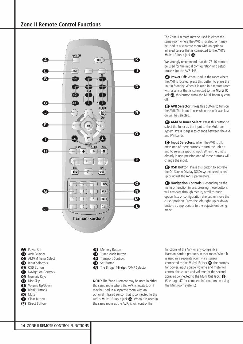
A Power OffB AVR SelectorC AM/FM Tuner SelectD Input SelectorsE OSD ButtonF Navigation ControlsG Numeric KeysH Disc SkipI Volume Up/DownJ Blank ButtonsK MuteL Clear ButtonM Direct Button
N Memory ButtonO Tuner Mode ButtonP Transport ControlsQ Set Button� The Bridge /DMP Selector
NOTE: The Zone II remote may be used in eitherthe same room where the AVR is located, or itmay be used in a separate room with anoptional infrared sensor that is connected to theAVR’s Multi IR input jack f. When it is used inthe same room as the AVR, it will control the
functions of the AVR or any compatible Harman Kardon products in that room. When itis used in a separate room via a sensorconnected to the Multi IR Jack f, the buttonsfor power, input source, volume and mute willcontrol the source and volume for the secondzone, as connected to the Multi Out Jacks •.(See page 47 for complete information on usingthe Multiroom system.)
The Zone II remote may be used in either thesame room where the AVR is located, or it maybe used in a separate room with an optionalinfrared sensor that is connected to the AVR’sMulti IR input jack �.
We strongly recommend that the ZR 10 remotebe used for the initial configuration and setupprocess for the AVR 445.
A Power Off: When used in the room wherethe AVR is located, press this button to place theunit in Standby. When it is used in a remote roomwith a sensor that is connected to the Multi IRjack �, this button turns the Multi-Room systemoff.
B AVR Selector: Press this button to turn onthe AVR. The input in use when the unit was laston will be selected.
C AM/FM Tuner Select: Press this button toselect the Tuner as the input to the Multiroomsystem. Press it again to change between the AMand FM bands.
D Input Selectors: When the AVR is off,press one of these buttons to turn the unit onand to select a specific input. When the unit isalready in use, pressing one of these buttons willchange the input.
E OSD Button: Press this button to activatethe On Screen Display (OSD) system used to setup or adjust the AVR’s parameters.
F Navigation Controls: Depending on themenu or function in use, pressing these buttonswill navigate through menus, scroll throughoption lists or configuration choices, or move thecursor position. Press the left, right, up or downbutton, as appropriate to the adjustment beingmade.
K
�
O
N
M
L
Q
J
D
P
J
G
H
I
F
J
C
B
E
A
30362_AVR445_ENG 20/11/06 14:56 Side 14
ZONE II REMOTE CONTROL FUNCTIONS 15
ENG
LISH
Zone II Remote Control Functions
G Numeric Keys: These buttons serve as aten-button numeric keypad to enter tuner presetpositions. They are also used to select channelnumbers when TV, VCR or Sat receiver has beenselected on the remote, or to select tracknumbers on a CD, DVD or LD player, dependingon how the remote has been programmed.
H Disc Skip: Press this button to change discson compatible Harman Kardon CD or DVDchangers.
I Volume Up/Down: When used in the roomwhere the AVR is located, press this button toraise or lower the volume in that room. When itis used in a remote room with a sensor that isconnected to the Multi IR Jack �, this buttonwill raise or lower the volume in the remoteroom.
J Blank Buttons: These buttons are notactive. Pressing them will not change or controlany function on the AVR 445 or other IR devices.
K Mute: When used in the room where theAVR is located, press this button to temporarilysilence the unit. When it is used in a remoteroom with a sensor that is connected to theMulti IR Jack �, this button will temporarilysilence the feed to the remote room only. Pressthe button again to return to the previousvolume level.Important Note: No matter in which room theZone II remote is used, as with the main remoteit is important to remember to press the InputSelector button D that corresponds to theunit you wish to operate befor you change thedevice to be controlled.
L Clear Button: Press this button to clearincorrect entries when using the remote to directlyenter a radio station’s frequency.
M Direct Button: Press this button when thetuner is in use to start the sequence for directentry of a station’s frequency. After pressing thebutton simply press the proper Numeric KeysG to select a station (See page 49 for moreinformation on the tuner).
N Memory Button: Press this button to entera radio station into the AVR’s preset memory. Twounderline indicators will flash at the right side ofthe Main Information Display ˜, you thenhave five seconds to enter a preset memorylocation using the Numeric Keys G. (Seepage 49 for more information.)
O Tuner Mode: Press this button when thetuner is in use to select between automatictuning and manual tuning. When the button ispressed so MANUAL appears in the MainInformation Display ˜, pressing the Tuningbuttons K will move the frequency up or downin single-step increments. When the FM band isin use and AUTO appears in the MainInformation Display ˜, pressing this buttonwill change to monaural reception making evenweek stations audible. (See page 49 for moreinformation.)
P Transport Control Buttons: These buttonsdo not have any functions for the AVR, but theyare programmed for the forward/reverse playoperation of a wide variety of Harman KardonCD or DVD players, and audio- or video-cassetterecorders.
Q Set Button: This button is used to enter settings into the AVR’s memory. It is also used inthe setup procedures for delay time, speakerconfiguration and channel output leveladjustment.
� Digital Media Player (DMP)Selector: When Harman Kardon’s (optional) is connected to DigitalMedia Player (DMP) Connector . and acompatible Apple® iPod® is docked in ,pressing this selector will select the iPod as theaudio source input device for the AVR 445. Inaddition, if a video display is connected to one ofthe Video Monitor Outputs �, the iPod’smessages will appear on screen, and in theUpper and Lower Display Lines ˜. The⁄/¤/‹/› Buttons EF, the Set ButtonFQ and the Transport Controls PPmay be used to navigate the iPod and to operatemany functions. See page 43, and the manualsfor The Bridge and your iPod for moreinformation.
30362_AVR445_ENG 20/11/06 14:56 Side 15

16 INSTALLATION AND CONNECTIONS
After unpacking the unit, and placing it on a solidsurface capable of supporting its weight, you willneed to make the connections to your audio andvideo equipment.
Audio Equipment Connections
We recommend that you use high-qualityinterconnect cables when making connections tosource equipment and recorders to preserve theintegrity of the signals.
When making connections to audio sourceequipment or speakers it is always a good practice to unplug the unit from the AC wall outlet. This prevents any possibility ofaccidentally sending audio or transient signals tothe speakers that may damage them.
1. Connect the analog output of a CD player tothe CD inputs .
NOTE: When the CD player has both fixed andvariable audio outputs it is best to use the fixedoutput unless you find that the input to thereceiver is so low that the sound is noisy, or sohigh that the signal is distorted.
2. Connect the analog Play/Out jacks of acassette deck, MD, CD-R or other audio recorderto the Tape Input jacks �. Connect the analogRecord/In jacks on the recorder to the TapeOutput jacks � on the AVR.
3. Connect the digital output of any digitalsources such as a CD or DVD changer or player,advanced video game, a digital satellite receiver,HDTV tuner or digital cable set-top box or theoutput of a compatible computer sound card tothe Optical and Coaxial Digital Inputs��*Ó.
4. Connect the Coaxial or Optical DigitalOutputs � on the rear panel of the AVR to thematching digital input connections on a CD-R orMiniDisc recorder.
5. Assemble the AM Loop Antenna supplied withthe unit as shown below. Connect it to the AMand GND screw terminals �.
6. Connect the supplied FM antenna to the FM(75 ohm) connection �. The FM antenna maybe an external roof antenna, an inside poweredor wire lead antenna or a connection from acable system. Note that if the antenna orconnection uses 300-ohm twin-lead cable, youshould use a 300-ohm-to-75-ohm adapter tomake the connection.
7. Connect the front, center and surroundspeaker outputs ���' to the respectivespeakers.
To ensure that all the audio signals are carried toyour speakers without loss of clarity orresolution, we suggest that you use high-qualityspeaker cable. Many brands of cable areavailable and the choice of cable may beinfluenced by the distance between yourspeakers and the receiver, the type of speakersyou use, personal preferences and other factors.Your dealer or installer is a valuable resource toconsult in selecting the proper cable.
Regardless of the brand of cable selected, we recommend that you use a cable constructed offine, multistrand copper with an area greater than2 mm2.
Cable with an area of 1.5 mm2 may be used forshort runs of less than 4 m. We do notrecommend that you use cables with an area lessthan 1 mm2 due to the power loss anddegradation in performance that will occur.
Cables that are run inside walls should have theappropriate markings to indicate listing with anyappropriate testing agency standards. Questionsabout running cables inside walls should bereferred to your installer or a licensed electricianwho is familiar with the applicable local buildingcodes in your area.
When connecting wires to the speakers, becertain to observe proper polarity. Note that thepositive (+) terminal of each speaker connectionnow carries a specific color code as noted onpage 7. However, most speakers will still use ared terminal for the postive (+) connection.Connect the “negative” or “black” wire to thesame terminal on both the receiver and thespeaker.
NOTE: While most speaker manufacturersadhere to an industry convention of using blackterminals for negative and red ones for positive,some manufacturers may vary from thisconfiguration. To assure proper phase andoptimal performance, consult the identificationplate on your speaker or the speaker’s manual toverify polarity. If you do not know the polarity ofyour speaker, ask your dealer for advice beforeproceeding, or consult the speaker’smanufacturer.
We also recommend that the length of cableused to connect speaker pairs be identical. Forexample, use the same length piece of cable toconnect the front-left and front-right orsurround-left and surround-right speakers, evenif the speakers are a different distance from theAVR.
8. Connections to a subwoofer are normallymade via a line level audio connection from theSubwoofer Output � to the line-level inputof a subwoofer with a built-in amplifier. When apassive subwoofer is used, the connection firstgoes to a power amplifier, which will beconnected to one or more subwoofer speakers.If you are using a powered subwoofer that doesnot have line-level input connections, follow theinstructions furnished with the speaker forconnection information.
9. If an external multi-channel audio source with5.1 or 7.1 outputs such as an external digitalprocessor/decoder, DVD-Audio or SACD player isused, connect the outputs of that device to the8-Channel Direct Inputs .
Analog Video EquipmentConnections
Analog video equipment is connected in the samemanner as audio components. Again, the use ofhigh-quality interconnect cables is recommendedto preserve signal quality.
1. Connect a VCR’s audio and video Play/Outjacks to the Video 1 or Video 2 In jacks �!#% on the rear panel. The Audio and VideoRecord/In jacks on the VCR should be connectedto the Video 1 Out jacks �& on the AVR.
Installation and Connections
30362_AVR445_ENG 20/11/06 14:56 Side 16
INSTALLATION AND CONNECTIONS 17
ENG
LISH
Installation and Connections
NOTE: When connecting a device such as adigital cable box or other set-top tuner productwith a digital audio output, we recommend thatyou connect both the digital and analog outputsof the product to your AVR. The audio inputpolling feature of the AVR will then be able tomake certain that you have a constant audiofeed, since it will automatically switch the audioinput to the analog jacks if the digital feed isinterrupted or not available for a particularchannel.
8. If you have a camcorder, video game or otheraudio/video device that is connected to the AVRon a temporary, rather than permanent basis,connect the audio, video and digital audio out-puts of that device to the Front Panel Inputs*ÓÔ. A device connected to the Video 4jacks Ô is selected as the Video 4 input, andconnected to the digital jacks *Ó it is select-ed as "Optical 4" or "Coaxial 4" input. (Seepage 43 for more information on input configu-ration.)
9. Connect the AVR to your video display usingone of the following connections, even if you willalso use an HDMI connection:
• If your video display has component videoinputs (Y/Pr/Pb), connect the ComponentVideo Outputs �.
• If your display does not have digital orcomponent video inputs, connect the VideoMonitor Output � on the AVR to thematching input on your display. Only oneconnection is needed, and S-video is the higherquality signal.
HDMI Connections
HDMI™ is the abbreviation for High-DefinitionMultimedia Interface, which is quickly becomingthe standard connection point betweenadvanced video/audio source products anddisplays, particularly for high-definition videosignals. HDMI is a digital connection, eliminatingthe need to convert signals back and forth fromdigital to analog.
Some source or display components in yoursystem may use DVI (Digital Video Interface) fordigital video connections. DVI carries the samedigital video signals as HDMI but uses a largerconnector and does not transport audio orcontrol signals. In most cases, you may mix andmatch DVI and HDMI digital video connectionsby using optional connector adapters. Note,however, that some DVI-equipped video displaysare not compatible with the HDCP copyprotection coding that is increasingly carried withsignals connected via HDMI. If you have anHDMI source and a DVI-equipped display, youmay occasionally be unable to view a program ifthe display does not include HDCP. This is not thefault of the AVR or your source; it simplyindicates that the video display is not compati-ble.
The AVR 445 is equipped for HDMI switching,which means that it is able to select either of thetwo HDMI inputs as the source that feeds yoursystem’s video display. This preserves the digitalsignal in its original form by passing it directlythrough from source to display. However, thisalso means that the AVR does not have access tothe signal and thus it is not able to add menus oron-screen messages to HDMI signals, or toprocess the audio that may be part of the signalin an HDMI connection.
Therefore, the following connections are requiredwhen the AVR 445 is used with HDMI sources:
• Connect the HDMI output of a source to eitherof the HDMI Inputs ".
• Connect the HDMI Output � of the AVR toan HDMI input on your display.
• Connect either an optical or coaxial digitalaudio output from the source to the AVR. Thedefault connections are Optical 3 � for asource connected to HDMI 1 " and Coaxial 3 � for a source connected to HDMI 2 ". You may use any digital or analogaudio source in conjunction with the HDMIinputs, but if it varies from the default youmust make a change to the input’s setting, asshown on page 24.
• Even when HDMI inputs are used, it is impor-tant to make sure that a component, S-videoor composite video connection is madebetween the AVR and your display. This isneeded to view both the setup menus and on-screen messages, and to view other (non-HDMI) video sources. The AVR 445 does notconvert analog video signals to HDMI.
2. Connect the analog audio and video outputsof a satellite receiver, cable TV converter or televi-sion set or any other video source to the Video 3 $ jacks.
3. Connect the analog audio and video outputsof a DVD or laser disc player to the DVD jacks� .
4. If any of the video source devices has analogcomponent video (Y/Pr/Pb) outputs, but notHDMI, connect them to Component VideoInputs ��. The chart on page 62 has thedefault settings for various source devices, butyou may make any connection and change theconfiguration setting using the IN/OUTSETUPmenu, as described on page 24.
5. The default video connection for a DVD playeris to use the Component Video Input 3 Jacks+ on the AVR, but you may change thisassignment in the IN/OUTSETUPmenu(see page 24). A DVD player’s composite and S-video outputs may also be connected to theDVD Video Inputs �.
6. The default audio connection for a DVD playeris to link the coaxial digital audio output on theDVD player to the Coaxial 1 Digital AudioInput �, but you may also make a connectionto either the Coaxial � or Optical � digitalinputs, or the Analog DVD Audio Inputs .You may change the assignment in theIN/OUTSETUPmenu as described on page24, or by using the front-panel Digital InputSelector Û.
7. If you wish to use a portable audio/videoproduct such as a camcorder, portable mediaplayer or digital still camera with the AVR, ormake a connection to a video game console orother source that may not always be connectedto the AVR, connect the video outputs of thesource to the Video 4 Input/Output Jacks Ôthat are behind the Front-Panel Door .If the source has digital audio outputs, connectthem to the Optical 4 Digital Input * or the Coaxial 4 Digital Jack Ó.
Connection Notes:When making connections to the ComponentVideo Inputs ��+ or the Coaxial � orOptical � digital audio inputs, it is a good ideato make note of which jacks are connected towhich source, using the Worksheet in theAppendix. This will help simplify the configurationprocess.
30362_AVR445_ENG 20/11/06 14:56 Side 17
18 INSTALLATION AND CONNECTIONS
Installation and Connections
SCART A/V Connections
For the connections described above your videodevice needs RCA (cinch) connectors or/and S-Video connectors for all Audio and Video signals:Any normal video device (Not SVHS or High 8)for only playback needs 3 RCA jacks, VCRs forrecord and playback even 6 RCA jacks. Any S-Video device (SVHS, High 8) needs 2 RCA(Audio) and 1 S-Video jack (Video), if it´s a play-back unit, or 4 RCA (Audio In/Out) and 2 S-Video (Video In/Out) jacks, if it´s a recordingVCR.
Many european video devices are equipped withRCA (Cinch) or S-Video jacks only partially, notfor all audio and video in/outputs needed asdescribed above, but with a so called Scart orEuro-AV connector (almost rectangular jack with21 pins, see drawings on next page).
In that case the following Scart to Cinch adaptersor cables are needed:
• Units for playback, such as satellite receivers,camcorders, DVD or LD players, need anadapter from Scart to 3 RCA plugs, see fig. 1(normal video devices) or from Scart to 2RCA+1 S-Video plugs, see fig. 4 (S-Videodevices).
• HiFi VCRs need an adapter from Scart to 6 RCAplugs, see fig. 2 (normal video), or from Scartto 4 Audio+2S-Video jacks, see fig. 5 (S-Video VCR). Read carefully the instructionattached to the adapter to find which of the sixplugs is used for the record signal to the VCR(connect with the AVR´s Out jacks) and for theplayback signal from the VCR (connect with theAVR´s In jacks). Do not misconnect Audio andVideo signals. Don´t hesitate to consult yourdealer, if you are uncertain.
• If you use only normal video devices the TVmonitor needs an adapter from 3 RCA plugs toScart (fig. 3) only. If also S-Video devices areused an adapter from 2 RCA+1S-Video plugsto Scart is needed additionally (fig. 6), connect-ed to the SCART input on your TV that is pro-vided for S-Video.
Note that only the video plugs (the "yellow"cinch plug in fig. 3 and the S-Video plug in fig. 6) must be connected to the TV MonitorOutput �, and the volume on the TV must bereduced to minimum.
Important Note for Adapter Cables:If the cinch connectors of the adapter you’ll useare labeled, connect the Audio and Video ”In”plugs with the corresponding Audio and Video”In” jacks on the AVR (and with a VCR connectthe ”Out” plugs to the ”Out” jacks on the AVR).Note that with some adapter types it may be justturned around: If no signal is audible/ visiblewhen the VCR is playing connect the “Out” plugsto the ”In” jacks on the AVR and turned around.If the adapter plugs are not labeled in that way,pay attention to the signal flow directions asshown in the diagrams above and in the instruc-tion attached to the adapter. If uncertain, don’thesitate to consult your dealer.
30362_AVR445_ENG 20/11/06 14:56 Side 18

INSTALLATION AND CONNECTIONS 19
ENG
LISH
Installation and Connections
Black
Yellow
Red
Figure 1:SCART/Cinch-Adapter for
playback;signal flow:
SCART → Cinch
Black
Red
Blue
Yellow
Green
White
Figure 2:SCART/Cinch-Adapter for
record and playback;signal flow:
SCART ↔ Cinch
Black
Yellow
Red
Figure 3:Cinch/SCART-Adapter for
playback;signal flow:
Cinch → SCART
Rot
Schwarz
S-Video In
Figure 4:SCART/S-Video Adapter
for playback;signal flow:
SCART → Cinch
Schwarz
Rot
Blau
Gelb
S-Video In
S-Video Out
Figure 5:SCART/S-Video Adapterfor record and playback;
signal flow:SCART ↔ Cinch
Rot
Schwarz
S-Video Out
Figure 6:SCART/S-Video Adapter
for playback;signal flow:
Cinch → SCART
Black
Yellow
Red
Black
Red
Blue1
Yellow
Green1
White
Black
Yellow
Red
Red
Black
S-Video In
Red
Black
S-Video Out
Black
Red
Blue1
Yellow
S-Video In
S-Video Out
1 Also other colours possible, e.g. brown and grey.
Important Note for the Use of SCART-Cinch Adapters:When video sources are connected to the TVdirectly with a SCART cable, specific controlsignals apart from Audio/Video signals will befed to the TV. These specific signals are: With allvideo sources, the signal for automatic inputselection that switches the TV automatically tothe appropriate input as soon as the videosource is started. And with DVD players, thesignals automatically turning the TV to 4:3/16:9format (with 16:9 TVs or with 4:3 TVs withselectable 16:9 format) and turning the RGBvideo decoder of the TV on or off, depending onthe DVD player´s setting. With any adapter cable,these control signals will be lost and theappropriate setting of the TV must be mademanually.
Note for RGB signal with SCART:If you use a unit providing RGB signals on aSCART output (as e.g. most DVD players do) andyou want to use that RGB signal, this SCARToutput must be connected directly to your TV.Although the AVR can switch three-way videosignals (like component signals Y/Pb/Pr), mostTVs need separate sync signals for RGB (alsowith SCART) that cannot be switched andprovided by the AVR.RGB signals can be pathed through the AVR onlywhen no separate sync signal is needed (see last”Video Connection Note” on page 16).
30362_AVR445_ENG 20/11/06 14:56 Side 19

20 INSTALLATION AND CONNECTIONS
System and Power ConnectionsThe AVR 445 is designed for flexible use withmultiroom systems, external control componentsand power amplifiers.
Main Room Remote Control ExtensionIf the receiver is placed behind a solid or smokedglass cabinet door, the obstruction may preventthe remote sensor from receiving commands.In this event, the remote sensor of any Harman Kardon or other compatible device, notcovered by the door, or an optional remotesensor may be used. Connect the Remote IROutput of that device or the output of theremote sensor to the Remote IR Input jack �.
If other components are also prevented fromreceiving remote commands, only one sensor isneeded. Simply use this unit’s sensor or a remoteeye by running a connection from the RemoteIR Output jack � to the Remote IR Inputjack on Harman Kardon or other compatibleequipment.
Multiroom IR LinkThe key to remote room operation is to link theremote room to the AVR’s location with wire foran infrared receiver and speakers or an amplifier.The remote room IR receiver (this can be anoptional IR receiver or any other remotableHarman Kardon device in the remote room withIR sensor integrated) should be connected to theAVR via standard coaxial cable. Connect theRemote IR Output of the device or of theoptional sensor with the Multiroom IR Inputjack � on the AVR’s rear panel.
If other Harman Kardon compatible source equip-ment is part of the main room installation, theRemote IR Output jack � on the rear panelshould be connected to the IR IN jack on thatsource device. This will enable the remote roomlocation to control source equipment functions.
When a remote IR sensor is used to control non-Harman Kardon source equipment, we recom-mend that you make a direct connection or usean optional, external IR “blaster” connected tothe Remote IR Carrier Output Jack ,. If youare in doubt as to which IR Output jack to usefor the equipment in your system, contact yourdealer or installer, or the manufacturer’s supportsite and ask whether the unit to be controlleduses “full carrier” or “stripped” carrier IRcommands. When “full carrier commands” areused, make the connection to the Remote IRCarrier Output Jack ,. Otherwise, make theconnection to the Remote IR Output Jack �as noted above.
NOTE: All remotely controlled components mustbe linked together in a “daisy chain”. Connectthe IR OUT jack of one unit to the IR IN of thenext to establish this chain.
Multiroom Audio ConnectionsDepending on your system`s requirement anddistance from the AVR to the remote room, threeoptions are available for audio connection:
Option 1: Use high-quality, shielded audio inter-connect phono cable from the AVR’s location tothe remote room. In the remote room, connectthe interconnect cable to a stereo power amplifi-er. The amplifier will be connected to the room’sspeakers. At the AVR, plug the audio interconnectcables into the Multiroom Output Jacks �on the AVR’s rear panel.
Option 2: Place the amplifier that will providepower to the remote location speakers in thesame room as the AVR, and connect theMultiroom Output jacks � on the rear panelof the AVR to the audio input of the remote roomamplifier. Use the appropriate speaker wire toconnect the optional power amplifier to theremote speakers. High-quality wire of at least 2.5 mm2 is recommended for long multiroomconnections.
Option 3: Taking advantage of the AVR’s built-inseven-channel amplifier, it is possible to use twoof the amplifier channels to power speakers inthe remote room. When using this option you willnot be able to use the full 7.1-channelcapabilities of the AVR in the main listeningroom, but you will be able to add anotherlistening room without additional external poweramplifiers. To use the internal amplifiers to powera remote zone, connect the speakers for theremote room location to the SurroundBack/Multiroom Speaker Outputs '. Beforeusing the remote room you will need to configurethe amplifiers for surround operation bychanging a setting in the Multiroom menu,following the instructions shown on page 47.
NOTE: For all options, you may connect anoptional IR sensor (Harman Kardon He 1000) inthe remote room to the AVR via an appropriatecable. Connect the sensor’s cable to theMultiroom IR Input � on the AVR and usethe Zone II remote to control the room volume.Alternatively, you may install an optional volumecontrol between the output of the amplifiers andthe speakers.
A-BUS Installation ConnectionsThe AVR is among the very few receiversavailable today that offers built-in A-BUS/READY ®
operation. When used with an optional A-BUSkeypad or control module, you have all thebenefits of remote zone operation without theneed for an external power amplifier.
To use the AVR with an approved A-BUS product,simply connect the keypad or module that is inthe remote room to the AVR using standard“Category 5” wiring that is properly rated for theinwall use specific to the installation. Terminatethe wiring at the receiver end to a standard RJ-45 jack in compliance with the instructionsfurnished with the A-BUS module.
No further installation or adjustment is needed,as the A-BUS connector on the AVR routes thesignals in and out of the keypad to their properdestination for power, signal source and control.The output fed to the A-BUS jack is determinedby the AVR’s multiroom system, and the menusmay be used as is.
RS-232 ConnectionsThe AVR is equipped with an RS-232 SerialConnection Port ) that may be used for twopurposes. When the port is connected to acompatible, optional, external computer, keypador control system the AVR is capable of bi-directional communications that enable theexternal system to control the AVR, and for theAVR to report status and handshake data back tothe controller. Use of the RS-232 port for thistype of control requires specific technicalknowledge, and we recommend that any connec-tion and programming for control be made by atrained installer or technician familiar with theequipment being used.
The physical connection to the AVR’s RS-232 portis a standard D-9 connection but to assurecompatible and proper operation, specificsoftware commands and pin wiring schemes maybe required.
Installation and Connections
30362_AVR445_ENG 20/11/06 14:56 Side 20
INSTALLATION AND CONNECTIONS 21
ENG
LISH
Installation and Connections
USB ConnectionsThe AVR 445 is one of the few A/V receivers tooffer a USB connection that may be used forboth playback of compatible audio content froma computer and for loading of system updates(when available).
The physical connection between a computer andthe AVR is a simple one, requiring only a cablewith a USB “A” type connector on one side and aUSB “Mini B” on the other.
Connect the larger, “A” connector on the cable toyour computer or a USB hub and the end withthe “Mini” USB connector to the USB Jack �on the AVR’s rear panel.
NOTES ON USB:• The USB jack on the AVR is for connection to a
computer, or to a hub connected to acomputer, only. DO NOT connect it directly toother devices such as card readers, USBmemory storage devices, external hard drives,USB accessories, digital cameras or cellularphones. Connection to these devices maycause damage to the device and/or the AVRthat is not covered by the AVR’s warranty.
• The AVR’s USB connection may only be usedfor audio playback and system upgrades. Itmay not be used for other purposes, such assystem control, video or still-image playback.
Trigger Jack ConnectionThe AVR is equipped with a low-voltage AmpTrigger Jack - that may be used to activateoptional, external power amplifiers, screenmotors, motorized blinds or other compatibleproducts that may be part of a home theaterinstallation. Once the connections are made,operation is seamless in that the low-voltagecontrol signal is sent to the screen, blinds orother device when the AVR is turned on, and it isturned off along with the AVR. Due to thecomplexity of interfacing with power-controlled devices, we stronglyrecommend that the installation be doneby a qualified installer.
The AVR’s trigger jack is a 3.5mm mono plugthat delivers a 5-volt DC signal to the center pin(“tip”) of the plug (+) with the outer shaft(“ring”) of the plug as the negative (–) or groundconnection.
AC Power ConnectionsThis unit is equipped with an accessory AC out-let. It may be used to power accessory devices,but should not be used with high-current drawequipment such as power amplifiers. The totalpower draw to the Switched Outlet � mustnot exceed 100 watts.
The Switched � outlet will receive power onlywhen the unit is on completely. This is recom-mended for devices that have no power switch ora mechanical power switch that may be left inthe “ON” position.
NOTE: Many audio and video products go into aStandby mode when they are used with switchedoutlets, and cannot be fully turned on using theoutlet alone without a remote control command.
The AVR features a removable power cord thatallows wires to be run to a complex installationso that the unit, itself, need not be installed untilit is ready for connection. When all connectionsdescribed above have been made, connect theAC Power cord to the AC Power Cord Jack �.
The AVR draws significantly more current thanother household devices such as computers thatuse removable power cords. For that reason, it isimportant that only the cord supplied with theunit (or a direct replacement of identicalcapacity) be used.
Once the power cord is connected, you arealmost ready to enjoy the AVR’s incredible powerand fidelity!
Speaker Selection
No matter which type or brand of speakers isused, the same model or brand of speaker shouldbe used for the front-left, center and front-rightspeakers. This creates a seamless front sound-stage and eliminates the possibility of distractingsonic disturbances that occur when a soundmoves across mismatched front-channelspeakers.
Speaker Placement
The placement of speakers in a multichannelhome-theater system can have a noticeableimpact on the quality of sound reproduced.
Depending on the type of center-channel speakerin use and your viewing device, place the centerspeaker either directly above or below your TV, orin the center behind a perforated front-projectionscreen.
Once the center-channel speaker is installed,position the left-front and right-front speakers sothat they are as far away from one another asthe center-channel speaker is from the preferredlistening position. Ideally, the front-channelspeakers should be placed so that their tweetersare no more than 60cm above or below thetweeter in the center-channel speaker.
They should also be at least 0.5 meter from yourTV set unless the speakers are magneticallyshielded to avoid colourings on the TV screen.Note that most speakers are not shielded, evenwith complete surround sets only the Centerspeaker may be.
Depending on the specifics of your roomacoustics and the type of speakers in use, youmay find that imaging is improved by moving thefront-left and front-right speakers slightly for-ward of the center-channel speaker. If possible,adjust all front loudspeakers so that they areaimed at ear height when you are seated in thelistening position.
Using these guidelines, you’ll find that it takessome experimentation to find the correct locationfor the front speakers in your particularinstallation. Don’t be afraid to move thingsaround until the system sounds correct. Optimizeyour speakers so that audio transitions across thefront of the room sound smooth.
When the AVR is used in 5.1-channel operation,the preferred location for surround speakers is onthe side walls of the room, at or slightly behindthe listening position. In a 7.1-channel system,both side surround and back surround speakersare required. The center of the speaker shouldface you (see below).
A 6.1 surround speaker adds an additional centerback surround speaker to the system, enablingyou to enjoy the benefits of advanced surroundmodes such as Dolby Digital EX, DTS-ES andHarman Kardon’s proprietary Logic 7/7.1processing.
To step up to a 6.1 system, first place thespeakers for a 5.1 system. The “sixth” speakershould ideally be placed at the center of theroom’s rear wall, pointing directly toward thefront center channel speaker.
30362_AVR445_ENG 20/11/06 14:56 Side 21
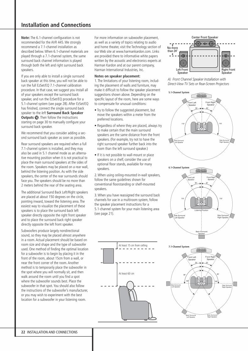
22 INSTALLATION AND CONNECTIONS
Installation and Connections
Note: The 6.1-channel configuration is notrecommended for the AVR 445. We stronglyrecommend a 7.1-channel installation asdescribed below. When 6.1-channel materials areplayed through a 7.1-channel system, the samesurround back channel information is playedthrough both the left and right surround backspeakers.
If you are only able to install a single surroundback speaker at this time, you will not be able torun the full EzSet/EQ 7.1-channel calibrationprocedure. In that case, we suggest you install allof your speakers except the surround backspeaker, and run the EzSet/EQ procedure for a5.1-channel system (see page 28). After EzSet/EQhas finished, connect the single surround backspeaker to the left Surround Back SpeakerOutputs �. Then follow the instructionsstarting on page 30 to manually configure yoursurround back speaker.
We recommend that you consider adding a sec-ond surround back speaker as soon as possible.
Rear surround speakers are required when a full7.1-channel system is installed, and they mayalso be used in 5.1 channel mode as an alterna-tive mounting position when it is not practical toplace the main surround speakers at the sides ofthe room. Speakers may be placed on a rear wall,behind the listening position. As with the sidespeakers, the center of the rear surrounds shouldface you. The speakers should be no more than 2 meters behind the rear of the seating area.
The additional Surround Back Left/Right speakersare placed at about 150 degrees on the circle,pointing inward, toward the listening area. Theeasiest way to visualize the placement of thesespeakers is to place the surround back leftspeaker directly opposite the right front speakerand to place the surround back right speakerdirectly opposite the left front speaker.
Subwoofers produce largely nondirectionalsound, so they may be placed almost anywherein a room. Actual placement should be based onroom size and shape and the type of subwooferused. One method of finding the optimal locationfor a subwoofer is to begin by placing it in thefront of the room, about 15cm from a wall, ornear the front corner of the room. Anothermethod is to temporarily place the subwoofer inthe spot where you will normally sit, and thenwalk around the room until you find a spotwhere the subwoofer sounds best. Place thesubwoofer in that spot. You should also followthe instructions of the subwoofer’s manufacturer,or you may wish to experiment with the bestlocation for a subwoofer in your listening room.
For more information on subwoofer placement,as well as a variety of topics relating to audioand home theater, visit the Technology section ofour Web site at www.harmankardon.com. Linksare provided there to informative white paperswritten by the acoustic and electronics experts atHarman Kardon and at our parent company,Harman International Industries, Inc.
Notes on speaker placement:1. The limitations of your listening room, includ-ing the placement of walls and furniture, maymake it difficult to follow the speaker placementsuggestions shown above. Depending on thespecific layout of the room, here are some waysto compensate for unusual conditions:
• Try to follow the suggested placement, butmove the speakers within a meter from thepreferred locations.
• Regardless of where they are placed, always tryto make certain that the main surroundspeakers are the same distance from the frontspeakers. (For example, try not to have theright surround speaker further back into theroom than the left surround speaker.)
• If it is not possible to wall-mount or placespeakers on a shelf, consider the use ofoptional floor stands, available for manyspeakers.
2. When using ceiling-mounted in-wall speakers,follow the same guidelines shown forconventional floorstanding or shelf-mountedspeakers.
3. When you have reassigned the surround backchannels for use in a multiroom system, followthe speaker placement instructions for a 5.1-channel system for your main listening area(see page 21).
A) Front Channel Speaker Installation withDirect-View TV Sets or Rear-Screen Projectors
At least 15 cm from celling
At least 60 cm
5.1-Channel System
6.1-Channel System
7.1-Channel System
30362_AVR445_ENG 20/11/06 14:56 Side 22

SYSTEM CONFIGURATION 23
ENG
LISH
System Configuration
Once the speakers have been placed in the roomand connected, the remaining steps are toprogram the system configuration memories.
Although it is necessary to assign input/outputsettings and surround mode choices manually,we recommend that you take advantage of thepower and precision of EzSet/EQ to automaticallyselect and enter the settings for all other audioparameters. This will not only save you time; itwill ensure that your room is calibrated andequalized with an accuracy not possible whenthese settings are made manually. You are nowready to power up the AVR to begin these finaladjustments.
First Turn OnYou are now ready to power up the AVR to beginthese final adjustments.
1. Make certain that the AC power cord is firmlyinserted in to the AC Power cord Recepticle� and plug the cord into an unswitched AC outlet. To maintian the unit's safety rating,DO NOT substitute the power cord for one withlower current capacity.
2. Press the Main Power Switch 1 in until itlatches and the word “OFF” on the top of theswitch disappears inside the front panel. Notethat the Power Indicator 3 will turn orange,indicating that the unit is in the Standby mode.
3. Remove the protective plastic film from themain front-panel lens. If left in place, the filmmay affect the performance of your remote control.
4. Install the four supplied AAA batteries in theremote as shown. Be certain to follow the (+)and (–) polarity indicators that are on the top ofthe battery compartment.
5. Turn the AVR on either by pressing the SystemPower Control 2 or the Input SourceSelector % on the front panel, or via theremote by pressing the Power On Button 3,AVR Selector 5 or any of the InputSelectors 46 on the remote. The PowerIndicator 3 will turn blue to confirm that theunit is on, and the Main Information Display˜ will also light up.
NOTE: After pressing one of the Input Selectorbuttons 4 to turn the unit on, press the AVRSelector 5 to have the remote control the AVRfunctions.
Using the On-Screen DisplayWhen making the following adjustments, youmay find them easier to make via the unit’s on-screen display system. These easy-to-readdisplays give you a clear picture of the currentstatus of the unit and facilitate speaker, delay,input or digital selection you are making.
To view the on-screen menus, make certain thatyou have made a video connection to theappropriate matching input of your TV orprojector. In order to view the AVR 445’s displays,the correct video source must be selected on thevideo display. On-screen menus may be viewedthrough component, S-video or composite videoconnections, but they are not available when anHDMI source is selected as the input or throughthe HDMI Output �.
IMPORTANT NOTE: When viewing the on-screenmenus using a CRT-based projector, plasma displayor any direct-view CRT monitor or television, it isimportant that they not be left on the screen for anextended period of time.As with any video display,but particularly with projectors, constant display ofa static image such as these menus or video gameimages may cause the image to be permanently“burned into” the CRT. This type of damage is notcovered by the AVR warranty and may not be cov-ered by the projector TV set’s warranty.
The AVR has two on-screen display modes,“Semi-OSD” and “Full-OSD.” When making con-figuration adjustments, it is recommended thatthe Full-OSD mode be used. This will place acomplete status report or option listing on thescreen, making it easier to view the availableoptions and make the settings on the screen. TheSemi-OSD mode uses one-line displays only.
Note that when the full OSD system is in use, themenu selections are not shown in the Informa-tion Display ˜. When the full OSD menu sys-tem is used, OSD ON will appear in the UpperDisplay Line ˜.
When the semi-OSD system is used in conjunctionwith the discrete configuration buttons, the onscreen display will show a single line of text withthe current menu selection. That selection will alsobe shown in the Upper or Lower Display Line˜.
The full OSD system can always be turned on oroff by pressing the OSD button L. When thisbutton is pressed the MASTERMENU(Figure 7) will appear, and adjustments are madefrom the individual menus. Note that the menuswill remain on the screen for 20 seconds afterthe latest action was made on the screen menu,then they will “time-out” and disappear from thescreen. The time-out may be increased to asmuch as 50 seconds by going to theADVANCEDSELECTmenu, and changingthe item titled FULLOSDTIMEOUT.
The semi-OSD system is also available as a sys-tem default, although it may be turned off byusing the ADVANCEDSELECTmenu. (Seepage 46). With the semi-OSD system, you maymake adjustments directly, by pressing the but-tons on the front panel or remote control for thespecific parameter to be adjusted. For example,to change the digital input for any of the sources,press the Digital Select Button ÛG andthen any of the Selector buttons ‹/› 7$ or⁄/¤ E on the front panel or remote.
Figure 7
The full-OSD menus remain on the screen fortwenty seconds after the last button press, afterwhich they “time out” and disappear from thescreen. The length of time menus remain on thescreen before the time-out may be increased toas long as fifty seconds by adjusting the settingsfor FULLOSDTIMEOUT in theADVANCEDSELECTmenu, as shown onpage 46.
NOTE: Semi-OSD messages are not availablewhen a 480p or any high definition image isbeing viewed.
System Setup
The AVR features an advanced memory systemthat enables you to establish differentconfigurations for component video assignment,digital input, surround mode for each inputsource. To ease the speaker setting, the samespeaker setting can also be made for all inputs.This flexibility enables you to custom tailor theway in which you listen to each source and havethe AVR memorize them. This means, forexample, that you may associate different sur-round modes and analog or digital inputs withdifferent sources. Once these settings are made,they will automatically be recalled whenever youselect that input.
To simplify initial configuration and operation,the AVR has been preconfigured with inputsettings that are typical for home theatersystems. These settings are detailed in theworksheets in the Appendix. Before adjusting theinput settings, it is a good idea to compare yourinput connections to the defaults so that youmay see where changes need to be made.
* * M A S T E R M E N U * *
IN/OUT SETUP
AUDIO ADJUST
SURROUND SETUP
EZSET/EQ
MULTI-ROOM
ADVANCED
→
30362_AVR445_ENG 20/11/06 14:56 Side 23

24 SYSTEM CONFIGURATION
Before using the unit, you will probably want tochange the settings for some inputs so that theyare properly configured to reflect the use ofdigital or analog inputs and the surround modeassociated with the input. Remember that sincethe AVR memorizes the settings for each inputindividually, you will need to make theseadjustments for each input used. However, oncethey are made, further adjustment is onlyrequired when system components are changed.
To make this process as quick and as easy aspossible, we suggest that you use the full-OSDsystem with the on-screen menus, and stepthrough each input.
In/Out SetupThe first step in configuring the AVR is to selectan input, i.e. to associate an analog or digitalinput with each input source in use, e.g. CD orDVD. Note that once an input is selected, allsettings for the Digital Input, Speaker Configura-tion and Surround Mode will ”attach” them-selves to that input and be stored in a non-volatile memory. This means that once made, theselection of an input will automatically recallthose settings. For that reason, the proceduresdescribed below must be repeated for each inputsource so that you have the opportunity tocustom tailor each source to your specificlistening requirements. However, once made theyneed not be changed again unless you need toalter a setting.
When using the full-OSD system to make thesetup adjustments, press the OSD button Lonce so that the MASTERMENU (Figure 7)appears. Note that the ➞ cursor will be next tothe IN/OUTSETUP line. Press the Setbutton F to enter the menu and theIN/OUTSETUPmenu (Figure 8) willappear on the screen. Press the ‹/› buttons Euntil the desired input name appears in thehighlighted video, as well as being indicated inthe front panel Input Indicators ˆ.
Figure 8
When any input other than the tuner, 8-channelinputs or USB input, is selected as the source,you have the option of renaming the input as itappears in the on-screen and front panel mes-sages. This is helpful if you have more than oneVCR, if you wish to associate a specific productbrand name with the input, or to simply enterany name that will help you to remember whichsource is being selected.
To change the input name, press the ⁄/¤
Navigation Button E on the remote so thatthe ➞ cursor is pointing to TITLE. Next, pressand hold the Set Button F for a few secondsuntil a flashing box appears to the right of thecolon. Immediately release the Set Button F,as you are now ready to enter the device name.
Press the ⁄/¤ Navigation Button E andnote that a complete set of alpha-numericcharacters will appear with the start of thealphabet in capital letters followed by the lower-case letters and then numbers and symbols.When you press the ¤ Navigation ButtonE, a series of symbols and numbers willappear, followed by a reverse list of the alphabetin lower-case letters. Press the button either wayuntil the first letter of the desired name appears.If you wish to enter a blank space as the firstcharacter, press the › Navigation Button E.
When the desired character appears, press the ›Navigation Button E and repeat the processfor the next letter, and continue until the desiredname is entered, up to a maximum of fourteencharacters.
Press the Set Button F to enter the inputname into the system memory and to proceedwith the configuration process.
The audio input defaults for all sources exceptthe Tuner, USB and 6/8-Channel Direct inputs areshown in the table in the Appendix. If yoursystem configuration follows the default table, nochanges are needed and you may press the⁄/¤ Navigation Button EF to move tothe next line.
With the cursor pointing to AUDIOIN-PORT, press the ‹/› NavigationButton EF to change the default to adifferent audio input connection. When the nameof the desired input appears, press the ⁄/¤
Navigation Button EF to move to thenext line.
In normal operation, when a digital audio streamis interrupted, the unit will automatically switchto the analog inputs associated with that source.This is particularly useful with cable set-top boxeswhere the input is normally digital, butoccasionally changes to analog. If you wish toconfigure an input so that the auto-poll circuit isturned off, while the on-screen cursor is pointingto the AUDIOAUTOPOLL line, simplypress the ‹/› Navigation Button EF sothat OFF (rather than ON) is in a white videohighlight.
When the desired auto-poll setting is entered,press the ⁄/¤ Navigation Button EF tomove to the next line.
When the cursor is at the VIDEOIN-PORTline, you are able to select an alternative to thedefault input setting for the video inputassociated with any source except HDMI 1 andHDMI 2. For the Video 1 and Video 4 inputs, thefactory default of AUTOwill select eithercomposite or S-video, depending on which hasan active signal. For the Video 2, Video 3 andDVD inputs, the AUTO setting will normallyselect the default component input, but if it isnot in use, the system will revert to a compositeor S-video output if either one is active.
You may set COMPONENTINPUT to OFFif you aren’t using component video, and the AVRwill not select the component video inputs.
To have the AVR always look to a specific sourceconnection when an input is selected, makecertain that the on-screen cursor is pointing tothe VIDEOIN-PORT line, and then pressthe ‹/› Navigation Button EF until thename of the desired input appears.
Note that this setting is not available when theHDMI inputs are selected. The choice of availableinputs may vary according to whether an audio-only source (such as the tuner, CD or tape) or anaudio/ video source (such as Video 1–Video 4 orDVD) is selected.
When the desired video input setting has beenmade, press the ⁄/¤ Navigation ButtonEF to move to the next line.
If your system includes any sources that areequipped with Y/Pr/Pb component video outputs,the AVR is able to switch them to send theproper signals to your video display. Each of theComponent Video Inputs JL� isassigned to a default source, as shown in thetable in the Appendix, but if you have connectedyour system differently than the factory settings,you may select any of the three inputs for anysource except the HDMI inputs or the Tuner. Ifyour system does not include component videoat this time, or if you do not need to changethese defaults, press the ¤ Navigation ButtonEF to go to the next setting.
To change the Component Video assignment,first make certain that the ➞ cursor is pointingto the COMPONENTIN line on the menuscreen, and then press the ‹/› NavigationButton EF until you see the desired inputin the highlighted video.
When the desired component input has beenselected, press the ¤ Navigation ButtonEF go to the next setting.
At the VIDEOPROCESS line, you are ableto select whether video format conversion, is tobe used with the input source being configured.If you do not need to change the setting, simplypress the ⁄/¤ Navigation Button EF tomove to the next line.
* I N / O U T S E T U P *
S O U R C E : V I D E O 1
T I T L E :
A U D I O I N - P O R T : A N A L O G
A U D I O A U T O P O L L : O N O F F
V I D E O I N - P O R T : A U T O
C O M P O N E N T I N P U T : C O M P 1
V I D E O P R O C E S S : V C O N V E R
A / V S Y N C D L A Y : 0 m S
M A S T E R M E N U P A G E 2
→
System Configuration
30362_AVR445_ENG 20/11/06 14:56 Side 24
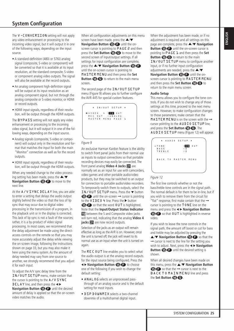
SYSTEM CONFIGURATION 25
ENG
LISH
System Configuration
The V-CONVERSION setting will not applyany video enhancement or processing to theincoming video signal, but it will output it in oneof the following ways, depending on the inputsource.
• A standard-definition (480i or 576i) analogsignal (composite, S-video or component) willbe converted so that it is available at its inputresolution, at the standard composite, S-videoor component analog video outputs. The signalwill also be available at the record outputs.
• An analog component high-definition signalwill be output at its input resolution as ananalog component signal, but not through theanalog composite or S-video monitor, or HDMIor record outputs.
• HDMI input signals, regardless of their resolu-tion, will be output through the HDMI outputs.
The BYPASS setting will not apply any videoenhancement or processing to the incomingvideo signal, but it will output it in one of the fol-lowing ways, depending on the input source.
• Analog signals (composite, S-video or compo-nent) will output only in the resolution and for-mat that matches the input for both the main“Monitor” connection as well as for the recordoutputs.
• HDMI input signals, regardless of their resolu-tion, will be output through the HDMI outputs.
When any needed change to the video process-ing setting has been made, press the ⁄/¤
Navigation Button EF to move to thenext line.
At the A/VSYNCDELAY line, you are ableto enter a setting that delays the audio outputslightly behind the video so that the loss of lipsync that may occur due to digital videoprocessing in the transmission of a program, inthe playback unit or in the display is corrected.This lack of lip sync is not a fault of the sources;rather, it is a by-product of video signalprocessing. In most cases, we recommend thatthe delay adjustment be made using the direct-access controls on the remote so that you maymore accurately adjust the delay while viewingthe on-screen image, following the instructionsshown on page 33, but you may also make ithere using the menu system. As the amount ofdelay needed may vary from one source toanother, we strongly recommend that you adjustit for each input.
To adjust the A/V sync delay time from theIN/OUTSETUPmenu, make certain thatthe cursor is pointing to the A/VSYNCDELAY line, and then press the ‹/›
Navigation Button EF until the desiredamount of delay is applied so that the on-screenvideo matches the audio.
When all configuration adjustments on this menuscreen have been made, press the ⁄/¤
Navigation Button EF until the on-screen cursor is pointing to PAGE2 and thenpress the Set Button FQ to move to thesecond screen of input/output settings. If allsettings for input configuration are complete,press the ⁄/¤ Navigation Button EFuntil the on-screen cursor is pointing toMASTERMENU and then press the SetButton FQ to return to the main menuscreen.
The second page of the IN/OUTSETUPmenu (Figure 9) allows you to further configurethe AVR 445 for special custom features.
Figure 9
An exclusive Harman Kardon feature is the abilityto switch front panel jacks from their normal useas inputs to output connections so that portablerecording devices may easily be connected. Thefront panel analog Video 4 Jacks Ô arenormally set as an input for use with camcorders,video games and other portable audio/videoproducts, but they may be switched to an outputfor connection to portable audio/video recorders.To temporarily switch them to outputs, select theIN/OUTSETUPmenu. Press the ¤ buttonEF until the on-screen ➞ cursor is pointingto the VIDEO 4 line. Press the › buttonEF so that the word OUT is highlighted.Note that the Input/Output Status Indicator( between the S and Composite video jackswill turn red, indicating that the analog Video 4jacks Ô are now record outputs.
Selection of the jacks as an output will remaineffective as long as the AVR is on. However, oncethe unit is turned off, the jack will revert to itsnormal use as an input when the unit is turned onagain.
The RECOUT line enables you to select whatthe audio output is at the analog record outputsfor the input source being configured. Press the‹/› Navigation Button EF to chooseone of the following if you wish to change thedefault setting:
• ANALOG selects an unprocessed pass-through of an analog source and is the defaultsetting for most inputs.
• DSPDOWNMIX selects a two-channeldownmix of a multichannel digital input.
When the adjustment has been made, or if noadjustment is required and all settings on thispage are complete, press the ⁄/¤ NavigationButton EF until the on-screen cursor ispointing to PAGE1 and then press the SetButton FQ to return to the mainIN/OUTSETUPmenu to configure anotherinput, or if no further input configurationadjustments are needed, press the ⁄/¤
Navigation Button EF until the on-screen cursor is pointing to MASTERMENUand then press the Set Button FQ toreturn to the main menu screen.
Audio SetupThis menu allows you to configure the tone con-trols. If you do not wish to change any of thosesettings at this time, proceed to the next menuscreen. However, to make configuration changesto those parameters, make certain that theMASTERMENU is on the screen with the ➞cursor pointing to the AUDIOSETUP line,and press the Set Button FQ. TheAUDIO SETUPmenu (Figure 12) will appear.
Figure 12
The first line controls whether or not thebass/treble tone controls are in the signal path.The normal default is for them to be in-line, but ifyou wish to remove them from the circuit for“flat” response, first make certain that the ➞cursor is pointing to the TONE line on themenu and press the ‹/› Navigation ButtonEF so that OUT is highlighted in reversevideo.
If you wish to leave the tone controls in thesignal path, the amount off boost or cut for bassand treble may be adjusted by pressing the⁄/¤ Navigation Button EF so that the➞ cursor is next to the line for the setting youwish to adjust. Next, press the ‹/› NavigationButton EF until the desired setting isshown.
When all desired changes have been made on this menu, press the ⁄/¤ Navigation ButtonEF so that the ➞ cursor is next to the BACK TO MAIN MENU line and press the Set Button FQ.
* A U D I O S E T U P *
T O N E : I N O U T
B A S S : 0
T R E B L E : 0
B A C K T O M A S T E R M E N U
→
* I N / O U T S E T U P *
V I D E O 4 : I N O U T
R E C O U T : A N A L O G
M A S T E R M E N U P A G E 1
➔ ➔
30362_AVR445_ENG 20/11/06 14:56 Side 25
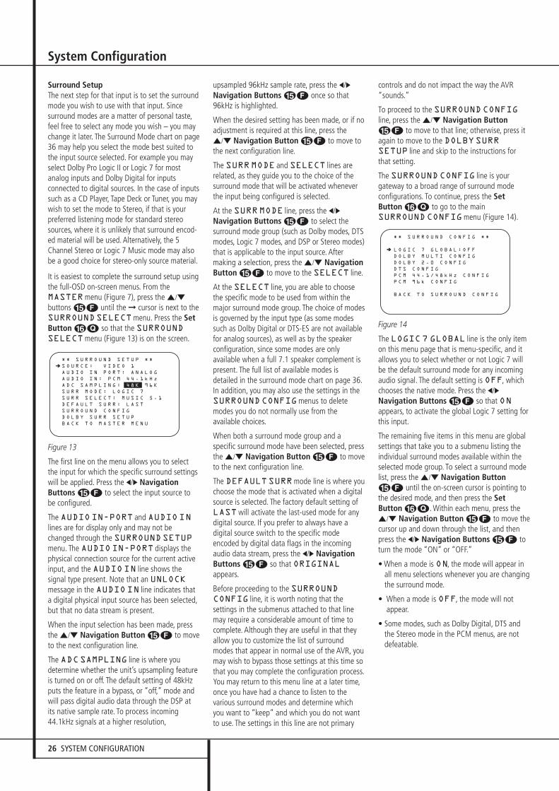
26 SYSTEM CONFIGURATION
System Configuration
Surround SetupThe next step for that input is to set the surroundmode you wish to use with that input. Sincesurround modes are a matter of personal taste,feel free to select any mode you wish – you maychange it later. The Surround Mode chart on page36 may help you select the mode best suited tothe input source selected. For example you mayselect Dolby Pro Logic II or Logic 7 for mostanalog inputs and Dolby Digital for inputsconnected to digital sources. In the case of inputssuch as a CD Player, Tape Deck or Tuner, you maywish to set the mode to Stereo, if that is yourpreferred listening mode for standard stereosources, where it is unlikely that surround encod-ed material will be used. Alternatively, the 5Channel Stereo or Logic 7 Music mode may alsobe a good choice for stereo-only source material.
It is easiest to complete the surround setup usingthe full-OSD on-screen menus. From theMASTERmenu (Figure 7), press the ⁄/¤
buttons EF until the ➞ cursor is next to theSURROUNDSELECTmenu. Press the SetButton FQ so that the SURROUNDSELECTmenu (Figure 13) is on the screen.
Figure 13
The first line on the menu allows you to selectthe input for which the specific surround settingswill be applied. Press the ‹/› NavigationButtons EF to select the input source tobe configured.
The AUDIOIN-PORT and AUDIOINlines are for display only and may not bechanged through the SURROUNDSETUPmenu. The AUDIOIN-PORT displays thephysical connection source for the current activeinput, and the AUDIOIN line shows thesignal type present. Note that an UNLOCKmessage in the AUDIOIN line indicates thata digital physical input source has been selected,but that no data stream is present.
When the input selection has been made, pressthe ⁄/¤ Navigation Button EF to moveto the next configuration line.
The ADCSAMPLING line is where youdetermine whether the unit’s upsampling featureis turned on or off. The default setting of 48kHzputs the feature in a bypass, or “off,” mode andwill pass digital audio data through the DSP atits native sample rate. To process incoming44.1kHz signals at a higher resolution,
upsampled 96kHz sample rate, press the ‹/›Navigation Buttons EF once so that96kHz is highlighted.
When the desired setting has been made, or if noadjustment is required at this line, press the⁄/¤ Navigation Button EF to move tothe next configuration line.
The SURRMODE and SELECT lines arerelated, as they guide you to the choice of thesurround mode that will be activated wheneverthe input being configured is selected.
At the SURRMODE line, press the ‹/›Navigation Buttons EF to select thesurround mode group (such as Dolby modes, DTSmodes, Logic 7 modes, and DSP or Stereo modes)that is applicable to the input source. Aftermaking a selection, press the ⁄/¤ NavigationButton EF to move to the SELECT line.
At the SELECT line, you are able to choosethe specific mode to be used from within themajor surround mode group. The choice of modesis governed by the input type (as some modessuch as Dolby Digital or DTS-ES are not availablefor analog sources), as well as by the speakerconfiguration, since some modes are onlyavailable when a full 7.1 speaker complement ispresent. The full list of available modes isdetailed in the surround mode chart on page 36.In addition, you may also use the settings in theSURROUNDCONFIGmenus to deletemodes you do not normally use from theavailable choices.
When both a surround mode group and aspecific surround mode have been selected, pressthe ⁄/¤ Navigation Button EF to moveto the next configuration line.
The DEFAULTSURRmode line is where youchoose the mode that is activated when a digitalsource is selected. The factory default setting ofLASTwill activate the last-used mode for anydigital source. If you prefer to always have adigital source switch to the specific modeencoded by digital data flags in the incomingaudio data stream, press the ‹/› NavigationButtons EF so that ORIGINALappears.
Before proceeding to the SURROUNDCONFIG line, it is worth noting that thesettings in the submenus attached to that linemay require a considerable amount of time tocomplete. Although they are useful in that theyallow you to customize the list of surroundmodes that appear in normal use of the AVR, youmay wish to bypass those settings at this time sothat you may complete the configuration process.You may return to this menu line at a later time,once you have had a chance to listen to thevarious surround modes and determine whichyou want to “keep” and which you do not wantto use. The settings in this line are not primary
controls and do not impact the way the AVR“sounds.”
To proceed to the SURROUNDCONFIGline, press the ⁄/¤ Navigation ButtonEF to move to that line; otherwise, press itagain to move to the DOLBYSURRSETUP line and skip to the instructions forthat setting.
The SURROUNDCONFIG line is yourgateway to a broad range of surround modeconfigurations. To continue, press the SetButton FQ to go to the mainSURROUNDCONFIGmenu (Figure 14).
Figure 14
The LOGIC7 GLOBAL line is the only itemon this menu page that is menu-specific, and itallows you to select whether or not Logic 7 willbe the default surround mode for any incomingaudio signal. The default setting is OFF, whichchooses the native mode. Press the ‹/›Navigation Buttons EF so that ONappears, to activate the global Logic 7 setting forthis input.
The remaining five items in this menu are globalsettings that take you to a submenu listing theindividual surround modes available within theselected mode group. To select a surround modelist, press the ⁄/¤ Navigation ButtonEF until the on-screen cursor is pointing tothe desired mode, and then press the SetButton FQ. Within each menu, press the⁄/¤ Navigation Button EF to move thecursor up and down through the list, and thenpress the ‹/› Navigation Buttons EF toturn the mode “ON” or “OFF.”
• When a mode is ON, the mode will appear inall menu selections whenever you are changingthe surround mode.
• When a mode is OFF, the mode will notappear.
• Some modes, such as Dolby Digital, DTS andthe Stereo mode in the PCM menus, are notdefeatable.
* * S U R R O U N D C O N F I G * *
L O G I C 7 G L O B A L : O F F
D O L B Y M U L T I C O N F I G
D O L B Y 2 . 0 C O N F I G
D T S C O N F I G
P C M 4 4 . 1 / 4 8 k H z C O N F I G
P C M 9 6 k C O N F I G
B A C K T O S U R R O U N D C O N F I G
➔ ➔
* * S U R R O U N D S E T U P * *
S O U R C E : V I D E O 1
A U D I O I N P O R T : A N A L O G
A U D I O I N : P C M 4 4 . 1 k H z
A D C S A M P L I N G : 4 8 K 9 6 K
S U R R M O D E : L O G I C 7
S U R R S E L E C T : M U S I C 5 . 1
D E F A U L T S U R R : L A S T
S U R R O U N D C O N F I G
D O L B Y S U R R S E T U P
B A C K T O M A S T E R M E N U
➔ ➔
30362_AVR445_ENG 20/11/06 14:56 Side 26
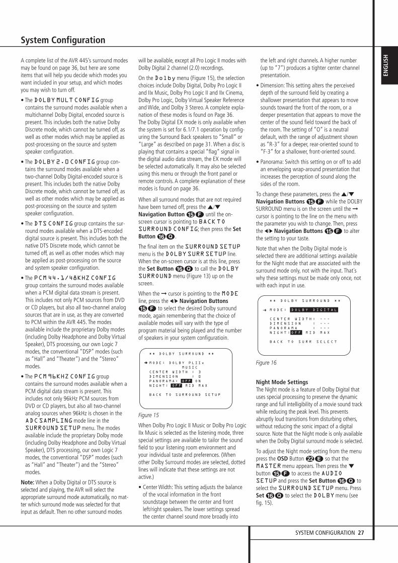
SYSTEM CONFIGURATION 27
ENG
LISH
System Configuration
A complete list of the AVR 445’s surround modesmay be found on page 36, but here are someitems that will help you decide which modes youwant included in your setup, and which modesyou may wish to turn off.
• The DOLBYMULTCONFIG groupcontains the surround modes available when amultichannel Dolby Digital, encoded source ispresent. This includes both the native DolbyDiscrete mode, which cannot be turned off, aswell as other modes which may be applied aspost-processing on the source and systemspeaker configuration.
• The DOLBY2.0CONFIG group con-tains the surround modes available when atwo-channel Dolby Digital-encoded source ispresent. This includes both the native DolbyDiscrete mode, which cannot be turned off, aswell as other modes which may be applied aspost-processing on the source and systemspeaker configuration.
• The DTSCONFIG group contains the sur-round modes available when a DTS-encodeddigital source is present. This includes both thenative DTS Discrete mode, which cannot beturned off, as well as other modes which maybe applied as post-processing on the sourceand system speaker configuration.
• The PCM44.1/48KHZCONFIGgroup contains the surround modes availablewhen a PCM digital data stream is present.This includes not only PCM sources from DVDor CD players, but also all two-channel analogsources that are in use, as they are convertedto PCM within the AVR 445. The modesavailable include the proprietary Dolby modes(including Dolby Headphone and Dolby VirtualSpeaker), DTS processing, our own Logic 7modes, the conventional “DSP” modes (suchas “Hall” and “Theater”) and the “Stereo”modes.
• The PCM96KHZCONFIG groupcontains the surround modes available when aPCM digital data stream is present. Thisincludes not only 96kHz PCM sources fromDVD or CD players, but also all two-channelanalog sources when 96kHz is chosen in theADCSAMPLINGmode line in theSURROUNDSETUPmenu. The modesavailable include the proprietary Dolby mode(including Dolby Headphone and Dolby VirtualSpeaker), DTS processing, our own Logic 7modes, the conventional “DSP” modes (suchas “Hall” and “Theater”) and the “Stereo”modes.
Note: When a Dolby Digital or DTS source isselected and playing, the AVR will select theappropriate surround mode automatically, no mat-ter which surround mode was selected for thatinput as default. Then no other surround modes
will be available, except all Pro Logic II modes withDolby Digital 2 channel (2.0) recordings.
On the Dolbymenu (Figure 15), the selectionchoices include Dolby Digital, Dolby Pro Logic IIand IIx Music, Dolby Pro Logic II and IIx Cinema,Dolby Pro Logic, Dolby Virtual Speaker Referenceand Wide, and Dolby 3 Stereo. A complete expla-nation of these modes is found on Page 36.The Dolby Digital EX mode is only available whenthe system is set for 6.1/7.1 operation by config-uring the Surround Back speakers to “Small” or“Large” as described on page 31. When a disc isplaying that contains a special “flag” signal inthe digital audio data stream, the EX mode willbe selected automatically. It may also be selectedusing this menu or through the front panel orremote controls. A complete explanation of thesemodes is found on page 36.
When all surround modes that are not requiredhave been turned off, press the ⁄/¤
Navigation Button EF until the on-screen cursor is pointing to BACKTOSURROUNDCONFIG; then press the SetButton FQ.
The final item on the SURROUNDSETUPmenu is the DOLBYSURRSETUP line.When the on-screen cursor is at this line, pressthe Set Button FQ to call the DOLBYSURROUNDmenu (Figure 13) up on thescreen.
When the ➞ cursor is pointing to the MODEline, press the ‹/› Navigation ButtonsEF to select the desired Dolby surroundmode, again remembering that the choice ofavailable modes will vary with the type ofprogram material being played and the numberof speakers in your system configuratioin.
Figure 15
When Dolby Pro Logic II Music or Dolby Pro LogicIIx Music is selected as the listening mode, threespecial settings are available to tailor the soundfield to your listening room environment andyour individual taste and preferences. (Whenother Dolby Surround modes are selected, dottedlines will indicate that these settings are notactive.)
• Center Width: This setting adjusts the balanceof the vocal information in the frontsoundstage between the center and frontleft/right speakers. The lower settings spreadthe center channel sound more broadly into
the left and right channels. A higher number(up to “7”) produces a tighter center channelpresentatioin.
• Dimension: This setting alters the perceiveddepth of the surround field by creating ashallower presentation that appears to movesounds toward the front of the room, or adeeper presentation that appears to move thecenter of the sound field toward the back ofthe room. The setting of “O” is a neutraldefault, with the range of adjustment shown as “R-3” for a deeper, rear-oriented sound to“F-3” for a shallower, front-oriented sound.
• Panorama: Switch this setting on or off to addan enveloping wrap-around presentation thatincreases the perception of sound along thesides of the room.
To change these parameters, press the ⁄/¤Navigation Buttons EF while the DOLBYSURROUND menu is on the screen until the ➞cursor is pointing to the line on the menu withthe parameter you wish to change. Then, pressthe ‹/› Navigation Buttons EF to alterthe setting to your taste.
Note that when the Dolby Digital mode isselected there are additional settings availablefor the Night mode that are associated with thesurround mode only, not with the input. That´swhy these settings must be made only once, notwith each input in use.
Figure 16
Night Mode SettingsThe Night mode is a feature of Dolby Digital thatuses special processing to preserve the dynamicrange and full intelligibility of a movie sound trackwhile reducing the peak level. This preventsabruptly loud transitions from disturbing others,without reducing the sonic impact of a digitalsource. Note that the Night mode is only availablewhen the Dolby Digital surround mode is selected.
To adjust the Night mode setting from the menupress the OSD Button LE so that theMASTERmenu appears. Then press the ¤button EF to access the AUDIOSETUP and press the Set Button FQ toselect the SURROUNDSETUPmenu. PressSet FQ to select the DOLBYmenu (seefig. 15).
* * D O L B Y S U R R O U N D * *
M O D E : D O L B Y D I G I T A L
C E N T E R W I D T H : - - -
D I M E N S I O N : - - -
P A N O R A M A : - - -
N I G H T : O F F M I D M A X
B A C K T O S U R R S E L E C T
* * D O L B Y S U R R O U N D * *
M O D E : D O L B Y P L I I x
M U S I C
C E N T E R W I D T H : 3
D I M E N S I O N : 0
P A N O R A M A : O F F O N
N I G H T : O F F M I D M A X
B A C K T O S U R R O U N D S E T U P
➔ ➔
30362_AVR445_ENG 20/11/06 14:56 Side 27
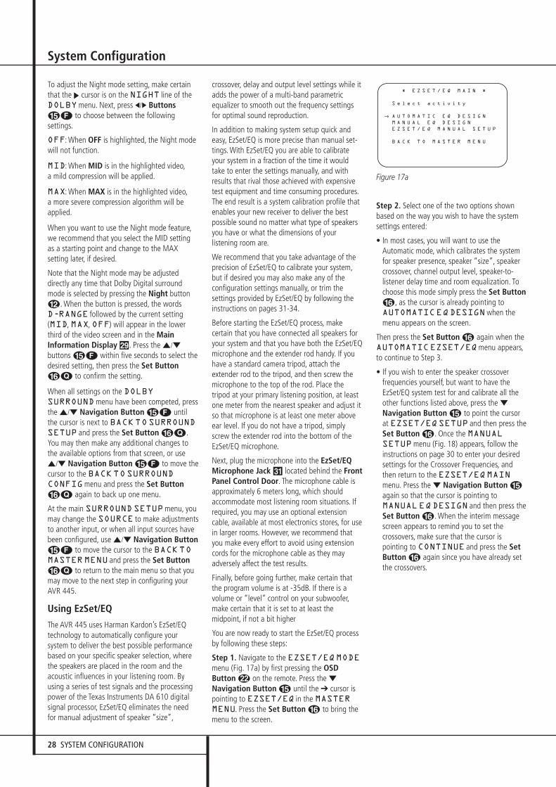
28 SYSTEM CONFIGURATION
System Configuration
To adjust the Night mode setting, make certainthat the › cursor is on the NIGHT line of theDOLBYmenu. Next, press ‹/› ButtonsEF to choose between the followingsettings.
OFF: When OFF is highlighted, the Night modewill not function.
MID: When MID is in the highlighted video,a mild compression will be applied.
MAX: When MAX is in the highlighted video,a more severe compression algorithm will beapplied.
When you want to use the Night mode feature,we recommend that you select the MID settingas a starting point and change to the MAXsetting later, if desired.
Note that the Night mode may be adjusteddirectly any time that Dolby Digital surroundmode is selected by pressing the Night buttonB. When the button is pressed, the words D-RANGE followed by the current setting(MID, MAX, OFF) will appear in the lowerthird of the video screen and in the MainInformation Display ˜. Press the ⁄/¤
buttons EF within five seconds to select thedesired setting, then press the Set ButtonFQ to confirm the setting.
When all settings on the DOLBYSURROUNDmenu have been competed, pressthe ⁄/¤ Navigation Button EF untilthe cursor is next to BACKTOSURROUNDSETUP and press the Set Button FQ.You may then make any additional changes tothe available options from that screen, or use⁄/¤ Navigation Button EF to move thecursor to the BACKTOSURROUNDCONFIGmenu and press the Set ButtonFQ again to back up one menu.
At the main SURROUNDSETUPmenu, youmay change the SOURCE to make adjustmentsto another input, or when all input sources havebeen configured, use ⁄/¤ Navigation ButtonEF to move the cursor to the BACKTOMASTERMENU and press the Set ButtonFQ to return to the main menu so that youmay move to the next step in configuring yourAVR 445.
Using EzSet/EQ
The AVR 445 uses Harman Kardon’s EzSet/EQtechnology to automatically configure yoursystem to deliver the best possible performancebased on your specific speaker selection, wherethe speakers are placed in the room and theacoustic influences in your listening room. Byusing a series of test signals and the processingpower of the Texas Instruments DA 610 digitalsignal processor, EzSet/EQ eliminates the needfor manual adjustment of speaker “size”,
crossover, delay and output level settings while itadds the power of a multi-band parametricequalizer to smooth out the frequency settingsfor optimal sound reproduction.
In addition to making system setup quick andeasy, EzSet/EQ is more precise than manual set-tings. With EzSet/EQ you are able to calibrateyour system in a fraction of the time it wouldtake to enter the settings manually, and withresults that rival those achieved with expensivetest equipment and time consuming procedures.The end result is a system calibration profile thatenables your new receiver to deliver the bestpossible sound no matter what type of speakersyou have or what the dimensions of yourlistening room are.
We recommend that you take advantage of theprecision of EzSet/EQ to calibrate your system,but if desired you may also make any of theconfiguration settings manually, or trim thesettings provided by EzSet/EQ by following theinstructions on pages 31-34.
Before starting the EzSet/EQ process, makecertain that you have connected all speakers foryour system and that you have both the EzSet/EQmicrophone and the extender rod handy. If youhave a standard camera tripod, attach theextender rod to the tripod, and then screw themicrophone to the top of the rod. Place thetripod at your primary listening position, at leastone meter from the nearest speaker and adjust itso that microphone is at least one meter aboveear level. If you do not have a tripod, simplyscrew the extender rod into the bottom of theEzSet/EQ microphone.
Next, plug the microphone into the EzSet/EQMicrophone Jack ˘ located behind the FrontPanel Control Door. The microphone cable isapproximately 6 meters long, which shouldaccommodate most listening room situations. Ifrequired, you may use an optional extensioncable, available at most electronics stores, for usein larger rooms. However, we recommend thatyou make every effort to avoid using extensioncords for the microphone cable as they mayadversely affect the test results.
Finally, before going further, make certain thatthe program volume is at -35dB. If there is avolume or “level” control on your subwoofer,make certain that it is set to at least themidpoint, if not a bit higher
You are now ready to start the EzSet/EQ processby following these steps:
Step 1. Navigate to the EZSET/EQMODEmenu (Fig. 17a) by first pressing the OSDButton L on the remote. Press the ¤Navigation Button E until the ➔ cursor ispointing to EZSET/EQ in the MASTERMENU. Press the Set Button F to bring themenu to the screen.
Figure 17a
Step 2. Select one of the two options shownbased on the way you wish to have the systemsettings entered:
• In most cases, you will want to use theAutomatic mode, which calibrates the systemfor speaker presence, speaker “size”, speakercrossover, channel output level, speaker-to-listener delay time and room equalization. Tochoose this mode simply press the Set ButtonF, as the cursor is already pointing toAUTOMATICEQDESIGNwhen themenu appears on the screen.
Then press the Set Button F again when theAUTOMATICEZSET/EQmenu appears,to continue to Step 3.
• If you wish to enter the speaker crossoverfrequencies yourself, but want to have theEzSet/EQ system test for and calibrate all theother functions listed above, press the ¤Navigation Button E to point the cursorat EZSET/EQSETUP and then press theSet Button F. Once the MANUALSETUPmenu (Fig. 18) appears, follow theinstructions on page 30 to enter your desiredsettings for the Crossover Frequencies, andthen return to the EZSET/EQMAINmenu. Press the ¤ Navigation Button Eagain so that the cursor is pointing toMANUALEQDESIGN and then press theSet Button F. When the interim messagescreen appears to remind you to set thecrossovers, make sure that the cursor ispointing to CONTINUE and press the SetButton F again since you have already setthe crossovers.
* E Z S E T / E Q M A I N *
S e l e c t a c t i v i t y
A U T O M A T I C E Q D E S I G N
M A N U A L E Q D E S I G N
E Z S E T / E Q M A N U A L S E T U P
B A C K T O M A S T E R M E N U
→
30362_AVR445_ENG 20/11/06 14:56 Side 28
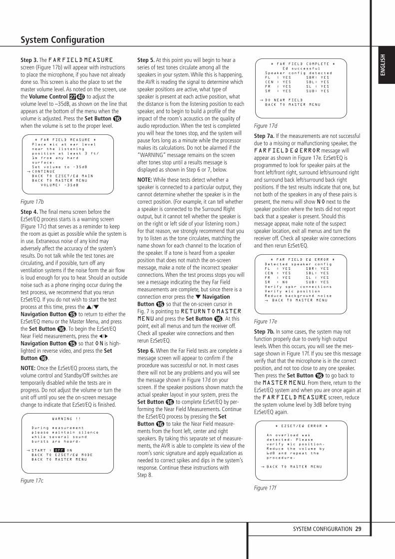
SYSTEM CONFIGURATION 29
ENG
LISH
System Configuration
Step 3. The FARFIELDMEASUREscreen (Figure 17b) will appear with instructionsto place the microphone, if you have not alreadydone so. This screen is also the place to set themaster volume level. As noted on the screen, usethe Volume Control ı to adjust thevolume level to –35dB, as shown on the line thatappears at the bottom of the menu when thevolume is adjusted. Press the Set Button Fwhen the volume is set to the proper level.
Figure 17b
Step 4. The final menu screen before theEzSet/EQ process starts is a warning screen(Figure 17c) that serves as a reminder to keepthe room as quiet as possible while the system isin use. Extraneous noise of any kind mayadversely affect the accuracy of the system’sresults. Do not talk while the test tones arecirculating, and if possible, turn off anyventilation systems if the noise form the air flowis loud enough for you to hear. Should an outsidenoise such as a phone ringing occur during thetest process, we recommend that you rerunEzSet/EQ. If you do not wish to start the testprocess at this time, press the ⁄/¤
Navigation Button E to return to either theEzSet/EQ menu or the Master Menu, and pressthe Set Button F. To begin the EzSet/EQNear Field measurements, press the ‹/›
Navigation Button E so that ON is high-lighted in reverse video, and press the SetButton F.
NOTE: Once the EzSet/EQ process starts, thevolume control and Standby/Off switches aretemporarily disabled while the tests are inprogress. Do not adjust the volume or turn theunit off until you see the on-screen messagechange to indicate that EzSet/EQ is finished.
Figure 17c
Step 5. At this point you will begin to hear aseries of test tones circulate among all thespeakers in your system. While this is happening,the AVR is reading the signal to determine whichspeaker positions are active, what type ofspeaker is present at each active position, whatthe distance is from the listening position to eachspeaker, and to begin to build a profile of theimpact of the room’s acoustics on the quality ofaudio reproduction. When the test is completedyou will hear the tones stop, and the system willpause fors long as a minute while the processormakes its calculations. Do not be alarmed if the“WARNING” message remains on the screenafter tones stop until a results message isdisplayed as shown in Step 6 or 7, below.
NOTE: While these tests detect whether aspeaker is connected to a particular output, theycannot determine whether the speaker is in thecorrect position. (For example, it can tell whethera speaker is connected to the Surround Rightoutput, but it cannot tell whether the speaker ison the right or left side of your listening room.)For that reason, we strongly recommend that youtry to listen as the tone circulates, matching thename shown for each channel to the location ofthe speaker. If a tone is heard from a speakerposition that does not match the on-screenmessage, make a note of the incorrect speakerconnections. When the test process stops you willsee a message indicating the they Far Fieldmeasurements are complete, but since there is aconnection error press the ¤ NavigationButton E so that the on-screen cursor in Fig. 7 is pointing to RETURNTOMASTERMENU and press the Set Button F. At thispoint, exit all menus and turn the receiver off.Check all speaker wire connections and thenrerun EzSet/EQ.
Step 6. When the Far Field tests are complete amessage screen will appear to confirm if theprocedure was successful or not. In most casesthere will not be any problems and you will seethe message shown in Figure 17d on yourscreen. If the speaker positions shown match theactual speaker layout in your system, press theSet Button F to complete EzSet/EQ by per-forming the Near Field Measurements. Continuethe EzSet/EQ process by pressing the SetButton F to take the Near Field measure-ments from the front left, center and rightspeakers. By taking this separate set of measure-ments, the AVR is able to complete its view of theroom’s sonic signature and apply equalization asneeded to correct spikes and dips in the system’sresponse. Continue these instructions with Step 8.
Figure 17d
Step 7a. If the measurements are not successfuldue to a missing or malfunctioning speaker, theFARFIELDEQERRORmessage willappear as shown in Figure 17e. EzSet/EQ isprogrammed to look for speaker pairs at thefront left/front right, surround left/surround rightand surround back left/surround back rightpositions. If the test results indicate that one, butnot both of the speakers in any of these pairs ispresent, the menu will show NO next to thespeaker position where the tests did not reportback that a speaker is present. Should thismessage appear, make note of the suspectspeaker location, exit all menus and turn thereceiver off. Check all speaker wire connectionsand then rerun EzSet/EQ.
Figure 17e
Step 7b. In some cases, the system may notfunction properly due to overly high outputlevels. When this occurs, you will see the mes-sage shown in Figure 17f. If you see this messageverify that that the microphone is in the correctposition, and not too close to any one speaker.Then press the Set Button F to go back tothe MASTERMENU. From there, return to theEzSet/EQ system and when you are once again atthe FARFIELDMEASURE screen, reducethe system volume level by 3dB before tryingEzSet/EQ again.
Figure 17f
* EZSET/EQ ERROR *
An overload was
detected. Please
verify mic position.
Reduce the volume by
6dB and repeat the
procedure.
BACK TO MASTER MENU
→
* FAR FIELD EQ ERROR *
Detected speaker config
FL : YES SBR: YES
CEN : YES SBL: YES
FR : YES SL : YES
SR : NO SUB: YES
Verify spkr connections
Verify mic position
Reduce background noise
→ BACK TO MASTER MENU
* FAR FIELD COMPLETE *
EQ successful
Speaker config detected
FL : YES SBR: YES
CEN : YES SBL: YES
FR : YES SL : YES
SR : YES SUB: YES
DO NEAR FIELD
BACK TO MASTER MENU
→
WARNING !!
During measurement
please maintain silence
while several sound
bursts are heard.
START : OFF ON
BACK TO EZSET/EQ MODE
BACK TO MASTER MENU
→
* FAR FIELD MEASURE *
Place mic at ear level
near the listening
position at least 3 ft/
1m from any hard
surface.
Set volume to -35dB
CONTINUE
BACK TO EZSET/EQ MAIN
BACK TO MASTER MENU
VOLUME: -35dB
→
30362_AVR445_ENG 20/11/06 14:56 Side 29
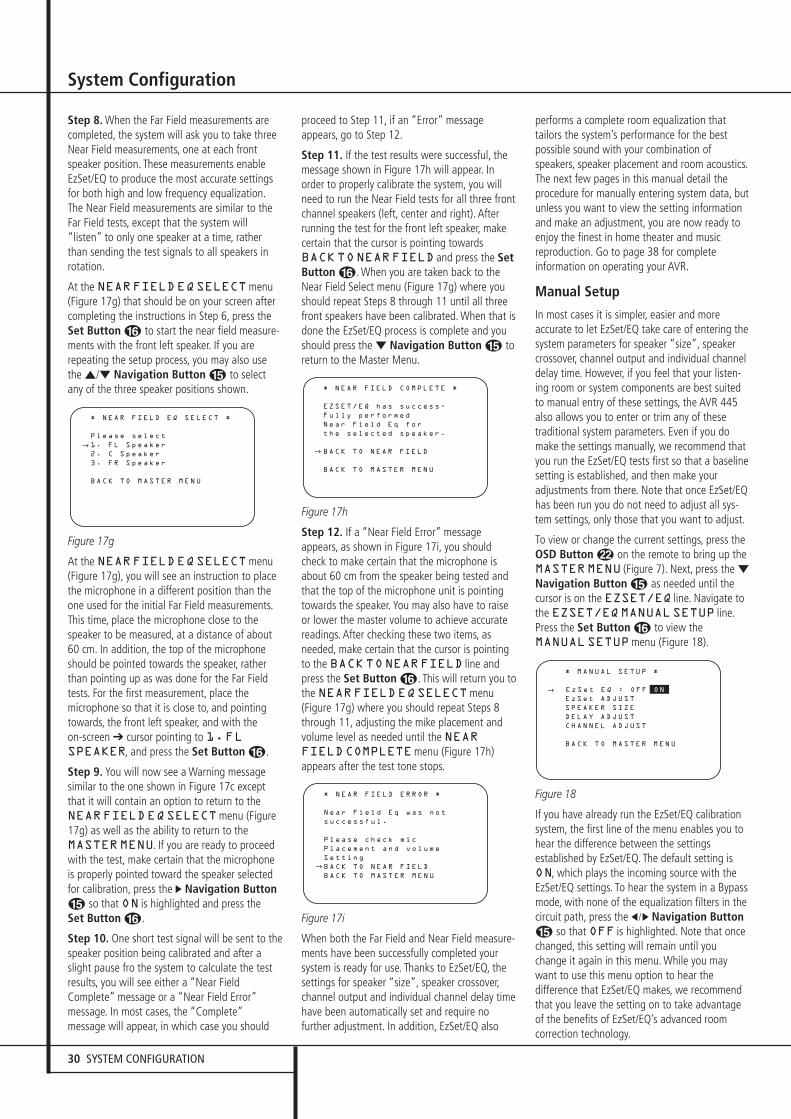
30 SYSTEM CONFIGURATION
System Configuration
Step 8. When the Far Field measurements arecompleted, the system will ask you to take threeNear Field measurements, one at each frontspeaker position. These measurements enableEzSet/EQ to produce the most accurate settingsfor both high and low frequency equalization.The Near Field measurements are similar to theFar Field tests, except that the system will“listen” to only one speaker at a time, ratherthan sending the test signals to all speakers inrotation.
At the NEARFIELDEQSELECTmenu(Figure 17g) that should be on your screen aftercompleting the instructions in Step 6, press theSet Button F to start the near field measure-ments with the front left speaker. If you arerepeating the setup process, you may also usethe ⁄/¤ Navigation Button E to selectany of the three speaker positions shown.
Figure 17g
At the NEARFIELDEQSELECTmenu(Figure 17g), you will see an instruction to placethe microphone in a different position than theone used for the initial Far Field measurements.This time, place the microphone close to thespeaker to be measured, at a distance of about60 cm. In addition, the top of the microphoneshould be pointed towards the speaker, ratherthan pointing up as was done for the Far Fieldtests. For the first measurement, place themicrophone so that it is close to, and pointingtowards, the front left speaker, and with the on-screen ➔ cursor pointing to 1.FLSPEAKER, and press the Set Button F.
Step 9. You will now see a Warning message similar to the one shown in Figure 17c exceptthat it will contain an option to return to theNEARFIELDEQSELECTmenu (Figure17g) as well as the ability to return to theMASTERMENU. If you are ready to proceedwith the test, make certain that the microphoneis properly pointed toward the speaker selectedfor calibration, press the › Navigation ButtonE so that ON is highlighted and press the Set Button F.
Step 10. One short test signal will be sent to thespeaker position being calibrated and after aslight pause fro the system to calculate the testresults, you will see either a “Near FieldComplete” message or a “Near Field Error”message. In most cases, the “Complete”message will appear, in which case you should
proceed to Step 11, if an “Error” messageappears, go to Step 12.
Step 11. If the test results were successful, themessage shown in Figure 17h will appear. Inorder to properly calibrate the system, you willneed to run the Near Field tests for all three frontchannel speakers (left, center and right). Afterrunning the test for the front left speaker, makecertain that the cursor is pointing towardsBACKTONEARFIELD and press the SetButton F. When you are taken back to theNear Field Select menu (Figure 17g) where youshould repeat Steps 8 through 11 until all threefront speakers have been calibrated. When that isdone the EzSet/EQ process is complete and youshould press the ¤ Navigation Button E toreturn to the Master Menu.
Figure 17h
Step 12. If a “Near Field Error” messageappears, as shown in Figure 17i, you shouldcheck to make certain that the microphone isabout 60 cm from the speaker being tested andthat the top of the microphone unit is pointingtowards the speaker. You may also have to raiseor lower the master volume to achieve accuratereadings. After checking these two items, asneeded, make certain that the cursor is pointingto the BACKTONEARFIELD line andpress the Set Button F. This will return you tothe NEARFIELDEQSELECTmenu(Figure 17g) where you should repeat Steps 8through 11, adjusting the mike placement andvolume level as needed until the NEARFIELDCOMPLETEmenu (Figure 17h)appears after the test tone stops.
Figure 17i
When both the Far Field and Near Field measure-ments have been successfully completed yoursystem is ready for use. Thanks to EzSet/EQ, thesettings for speaker “size”, speaker crossover,channel output and individual channel delay timehave been automatically set and require nofurther adjustment. In addition, EzSet/EQ also
performs a complete room equalization thattailors the system’s performance for the bestpossible sound with your combination ofspeakers, speaker placement and room acoustics.The next few pages in this manual detail theprocedure for manually entering system data, butunless you want to view the setting informationand make an adjustment, you are now ready toenjoy the finest in home theater and musicreproduction. Go to page 38 for completeinformation on operating your AVR.
Manual Setup
In most cases it is simpler, easier and moreaccurate to let EzSet/EQ take care of entering thesystem parameters for speaker “size”, speakercrossover, channel output and individual channeldelay time. However, if you feel that your listen-ing room or system components are best suitedto manual entry of these settings, the AVR 445also allows you to enter or trim any of thesetraditional system parameters. Even if you domake the settings manually, we recommend thatyou run the EzSet/EQ tests first so that a baselinesetting is established, and then make youradjustments from there. Note that once EzSet/EQhas been run you do not need to adjust all sys-tem settings, only those that you want to adjust.
To view or change the current settings, press the OSD Button L on the remote to bring up theMASTERMENU (Figure 7). Next, press the ¤Navigation Button E as needed until thecursor is on the EZSET/EQ line. Navigate tothe EZSET/EQMANUALSETUP line.Press the Set Button F to view theMANUALSETUPmenu (Figure 18).
Figure 18
If you have already run the EzSet/EQ calibrationsystem, the first line of the menu enables you tohear the difference between the settingsestablished by EzSet/EQ. The default setting isON, which plays the incoming source with theEzSet/EQ settings. To hear the system in a Bypassmode, with none of the equalization filters in thecircuit path, press the ‹/› Navigation ButtonE so that OFF is highlighted. Note that oncechanged, this setting will remain until youchange it again in this menu. While you maywant to use this menu option to hear thedifference that EzSet/EQ makes, we recommendthat you leave the setting on to take advantageof the benefits of EzSet/EQ’s advanced roomcorrection technology.
* MANUAL SETUP *
→ EzSet EQ : OFF ON
EzSet ADJUST
SPEAKER SIZE
DELAY ADJUST
CHANNEL ADJUST
BACK TO MASTER MENU
* NEAR FIELD ERROR *
Near Field Eq was not
successful.
Please check mic
Placement and volume
Setting
BACK TO NEAR FIELD
BACK TO MASTER MENU
→
* NEAR FIELD COMPLETE *
EZSET/EQ has success-
Fully performed
Near Field Eq for
the selected speaker.
BACK TO NEAR FIELD
BACK TO MASTER MENU
→
* NEAR FIELD EQ SELECT *
Please select
1. FL Speaker
2. C Speaker
3. FR Speaker
BACK TO MASTER MENU
→
30362_AVR445_ENG 20/11/06 14:56 Side 30
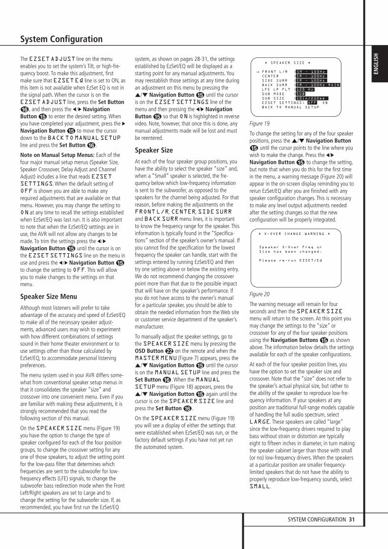
SYSTEM CONFIGURATION 31
ENG
LISH
System Configuration
The EZSETADJUST line on the menuenables you to set the system’s Tilt, or high-fre-quency boost. To make this adjustment, firstmake sure that EZSETEQ line is set to ON, asthis item is not available when EzSet EQ is not inthe signal path. When the cursor is on theEZSETADJUST line, press the Set ButtonF, and then press the ‹/› NavigationButton E to enter the desired setting. Whenyou have completed your adjustment, press the ›Navigation Button E to move the cursordown to the BACKTOMANUALSETUPline and press the Set Button F.
Note on Manual Setup Menus: Each of thefour major manual setup menus (Speaker Size,Speaker Crossover, Delay Adjust and ChannelAdjust) includes a line that reads EZSETSETTINGS. When the default setting ofOFF is shown you are able to make anyrequired adjustments that are available on thatmenu. However, you may change the setting toON at any time to recall the settings establishedwhen EzSet/EQ was last run. It is also importantto note that when the EzSet/EQ settings are inuse, the AVR will not allow any changes to bemade. To trim the settings press the ‹/›
Navigation Button E until the cursor is onthe EZSETSETTINGS line on the menu inuse and press the ‹/› Navigation Button Eto change the setting to OFF. This will allowyou to make changes to the settings on thatmenu.
Speaker Size Menu
Although most listeners will prefer to takeadvantage of the accuracy and speed of EzSet/EQto make all of the necessary speaker adjust-ments, advanced users may wish to experimentwith how different combinations of settingssound in their home theater environment or touse settings other than those calculated byEzSet/EQ, to accommodate personal listeningpreferences.
The menu system used in your AVR differs some-what from conventional speaker setup menus inthat it consolidates the speaker “size” andcrossover into one convenient menu. Even if youare familiar with making these adjustments, it isstrongly recommended that you read thefollowing section of this manual.
On the SPEAKERSIZEmenu (Figure 19)you have the option to change the type ofspeaker configured for each of the four positiongroups, to change the crossover setting for anyone of those speakers, to adjust the setting pointfor the low-pass filter that determines whichfrequencies are sent to the subwoofer for low-frequency effects (LFE) signals, to change thesubwoofer bass redirection mode when the FrontLeft/Right speakers are set to Large and tochange the setting for the subwoofer size. If, asrecommended, you have first run the EzSet/EQ
system, as shown on pages 28-31, the settingsestablished by EzSet/EQ will be displayed as astarting point for any manual adjustments. Youmay reestablish those settings at any time duringan adjustment on this menu by pressing the⁄/¤ Navigation Button E until the cursoris on the EZSETSETTINGS line of themenu and then pressing the ‹/› NavigationButton E so that ON is highlighted in reversevideo. Note, however, that once this is done, anymanual adjustments made will be lost and mustbe reentered.
Speaker Size
At each of the four speaker group positions, youhave the ability to select the speaker “size” and,when a “Small” speaker is selected, the fre-quency below which low-frequency informationis sent to the subwoofer, as opposed to thespeakers for the channel being adjusted. For thatreason, before making the adjustments on theFRONTL/R, CENTER, SIDESURRand BACKSURRmenu lines, it is importantto know the frequency range for the speaker. Thisinformation is typically found in the “Specifica-tions” section of the speaker’s owner’s manual. Ifyou cannot find the specification for the lowestfrequency the speaker can handle, start with thesettings entered by running EzSet/EQ and thentry one setting above or below the existing entry.We do not recommend changing the crossoverpoint more than that due to the possible impactthat will have on the speaker’s performance. Ifyou do not have access to the owner’s manualfor a particular speaker, you should be able toobtain the needed information from the Web siteor customer service department of the speaker’smanufacturer.
To manually adjust the speaker settings, go tothe SPEAKERSIZEmenu by pressing the OSD Button L on the remote and when theMASTERMENU (Figure 7) appears, press the⁄/¤ Navigation Button E until the cursoris on the MANUALSETUP line and press theSet Button F. When the MANUALSETUPmenu (Figure 18) appears, press the⁄/¤ Navigation Button E again until thecursor is on the SPEAKERSIZE line and press the Set Button F.
On the SPEAKERSIZEmenu (Figure 19) you will see a display of either the settings that were established when EzSet/EQ was run, or the factory default settings if you have not yet run the automated system.
Figure 19
To change the setting for any of the four speakerpositions, press the ⁄/¤ Navigation ButtonE until the cursor points to the line where youwish to make the change. Press the ‹/›Navigation Button E to change the setting,but note that when you do this for the first timein the menu, a warning message (Figure 20) willappear in the on-screen display reminding you torerun EzSet/EQ after you are finished with anyspeaker configuration changes. This is necessaryto make any level output adjustments neededafter the setting changes so that the newconfiguration will be properly integrated.
Figure 20
The warning message will remain for fourseconds and then the SPEAKERSIZEmenu will return to the screen. At this point youmay change the settings to the “size” orcrossover for any of the four speaker positionsusing the Navigation Buttons E as shownabove. The information below details the settingsavailable for each of the speaker configurations.
At each of the four speaker position lines, youhave the option to set the speaker size andcrossover. Note that the “size” does not refer tothe speaker’s actual physical size, but rather tothe ability of the speaker to reproduce low-fre-quency information. If your speakers at anyposition are traditional full-range models capableof handling the full audio spectrum, selectLARGE. These speakers are called “large”since the low-frequency drivers required to playbass without strain or distortion are typicallyeight to fifteen inches in diameter, in turn makingthe speaker cabinet larger than those with small(or no) low-frequency drivers. When the speakersat a particular position are smaller frequency-limited speakers that do not have the ability toproperly reproduce low-frequency sounds, selectSMALL.
* X-OVER CHANGE WARNING *
Speaker X-Over Freq or
Size has been changed.
Please re-run EZSET/EQ
* SPEAKER SIZE *
→ FRONT L/R :SM - 100Hz
CENTER :SM - 100Hz
SIDE SURR :SM - 100Hz
BACK SURR :SM - 100Hz MAIN
LFE LP FLT :120 Hz
SUB MODE :SUB
SUB SIZE :10in/250mm
EZSET SETTINGS: OFF ON
BACK TO MANUAL SETUP
30362_AVR445_ENG 20/11/06 14:56 Side 31
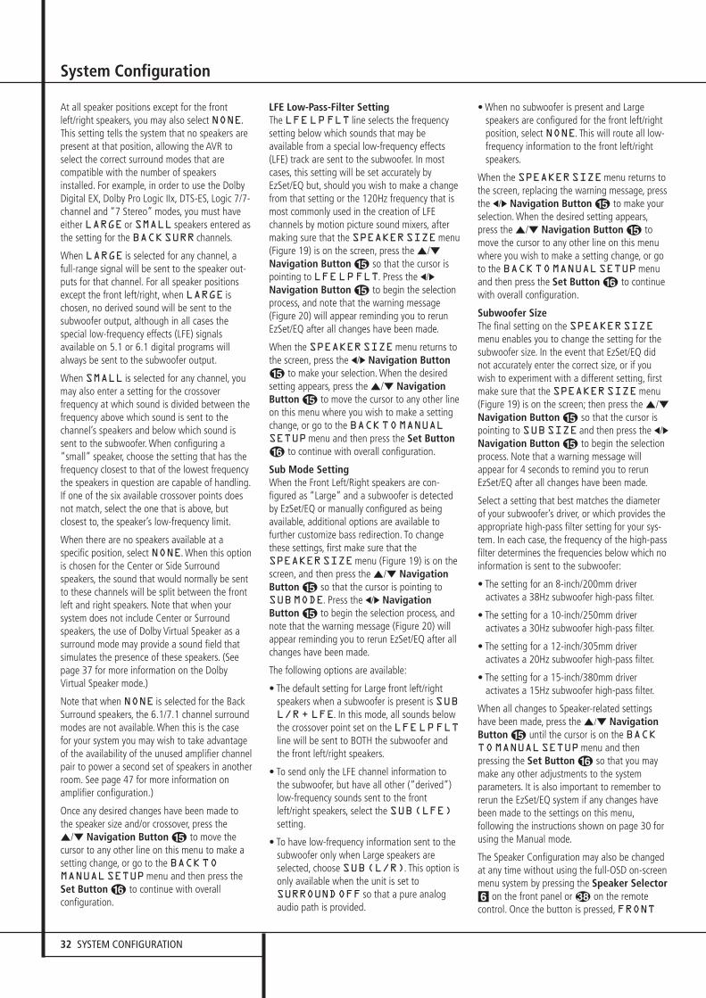
32 SYSTEM CONFIGURATION
System Configuration
At all speaker positions except for the frontleft/right speakers, you may also select NONE.This setting tells the system that no speakers arepresent at that position, allowing the AVR toselect the correct surround modes that arecompatible with the number of speakersinstalled. For example, in order to use the DolbyDigital EX, Dolby Pro Logic IIx, DTS-ES, Logic 7/7-channel and “7 Stereo” modes, you must haveeither LARGE or SMALL speakers entered asthe setting for the BACKSURR channels.
When LARGE is selected for any channel, afull-range signal will be sent to the speaker out-puts for that channel. For all speaker positionsexcept the front left/right, when LARGE ischosen, no derived sound will be sent to thesubwoofer output, although in all cases thespecial low-frequency effects (LFE) signalsavailable on 5.1 or 6.1 digital programs willalways be sent to the subwoofer output.
When SMALL is selected for any channel, youmay also enter a setting for the crossoverfrequency at which sound is divided between thefrequency above which sound is sent to thechannel’s speakers and below which sound issent to the subwoofer. When configuring a“small” speaker, choose the setting that has thefrequency closest to that of the lowest frequencythe speakers in question are capable of handling.If one of the six available crossover points doesnot match, select the one that is above, butclosest to, the speaker’s low-frequency limit.
When there are no speakers available at aspecific position, select NONE. When this optionis chosen for the Center or Side Surroundspeakers, the sound that would normally be sentto these channels will be split between the frontleft and right speakers. Note that when yoursystem does not include Center or Surroundspeakers, the use of Dolby Virtual Speaker as asurround mode may provide a sound field thatsimulates the presence of these speakers. (Seepage 37 for more information on the DolbyVirtual Speaker mode.)
Note that when NONE is selected for the BackSurround speakers, the 6.1/7.1 channel surroundmodes are not available. When this is the casefor your system you may wish to take advantageof the availability of the unused amplifier channelpair to power a second set of speakers in anotherroom. See page 47 for more information onamplifier configuration.)
Once any desired changes have been made tothe speaker size and/or crossover, press the⁄/¤ Navigation Button E to move thecursor to any other line on this menu to make asetting change, or go to the BACKTOMANUALSETUPmenu and then press theSet Button F to continue with overallconfiguration.
LFE Low-Pass-Filter SettingThe LFELPFLT line selects the frequencysetting below which sounds that may beavailable from a special low-frequency effects(LFE) track are sent to the subwoofer. In mostcases, this setting will be set accurately byEzSet/EQ but, should you wish to make a changefrom that setting or the 120Hz frequency that ismost commonly used in the creation of LFEchannels by motion picture sound mixers, aftermaking sure that the SPEAKERSIZEmenu(Figure 19) is on the screen, press the ⁄/¤Navigation Button E so that the cursor ispointing to LFELPFLT. Press the ‹/›Navigation Button E to begin the selectionprocess, and note that the warning message(Figure 20) will appear reminding you to rerunEzSet/EQ after all changes have been made.
When the SPEAKERSIZEmenu returns tothe screen, press the ‹/› Navigation ButtonE to make your selection. When the desiredsetting appears, press the ⁄/¤ NavigationButton E to move the cursor to any other lineon this menu where you wish to make a settingchange, or go to the BACKTOMANUALSETUPmenu and then press the Set ButtonF to continue with overall configuration.
Sub Mode SettingWhen the Front Left/Right speakers are con-figured as “Large” and a subwoofer is detectedby EzSet/EQ or manually configured as beingavailable, additional options are available tofurther customize bass redirection. To changethese settings, first make sure that theSPEAKERSIZEmenu (Figure 19) is on thescreen, and then press the ⁄/¤ NavigationButton E so that the cursor is pointing toSUBMODE. Press the ‹/› NavigationButton E to begin the selection process, andnote that the warning message (Figure 20) willappear reminding you to rerun EzSet/EQ after allchanges have been made.
The following options are available:
• The default setting for Large front left/rightspeakers when a subwoofer is present is SUBL/R+ LFE. In this mode, all sounds belowthe crossover point set on the LFELPFLTline will be sent to BOTH the subwoofer andthe front left/right speakers.
• To send only the LFE channel information tothe subwoofer, but have all other (“derived”)low-frequency sounds sent to the frontleft/right speakers, select the SUB(LFE)setting.
• To have low-frequency information sent to thesubwoofer only when Large speakers areselected, choose SUB(L/R). This option isonly available when the unit is set toSURROUNDOFF so that a pure analogaudio path is provided.
• When no subwoofer is present and Largespeakers are configured for the front left/rightposition, select NONE. This will route all low-frequency information to the front left/rightspeakers.
When the SPEAKERSIZEmenu returns tothe screen, replacing the warning message, pressthe ‹/› Navigation Button E to make yourselection. When the desired setting appears,press the ⁄/¤ Navigation Button E tomove the cursor to any other line on this menuwhere you wish to make a setting change, or goto the BACKTOMANUALSETUPmenuand then press the Set Button F to continuewith overall configuration.
Subwoofer SizeThe final setting on the SPEAKERSIZEmenu enables you to change the setting for thesubwoofer size. In the event that EzSet/EQ didnot accurately enter the correct size, or if youwish to experiment with a different setting, firstmake sure that the SPEAKERSIZEmenu(Figure 19) is on the screen; then press the ⁄/¤Navigation Button E so that the cursor ispointing to SUBSIZE and then press the ‹/›Navigation Button E to begin the selectionprocess. Note that a warning message willappear for 4 seconds to remind you to rerunEzSet/EQ after all changes have been made.
Select a setting that best matches the diameterof your subwoofer’s driver, or which provides theappropriate high-pass filter setting for your sys-tem. In each case, the frequency of the high-passfilter determines the frequencies below which noinformation is sent to the subwoofer:
• The setting for an 8-inch/200mm driver activates a 38Hz subwoofer high-pass filter.
• The setting for a 10-inch/250mm driver activates a 30Hz subwoofer high-pass filter.
• The setting for a 12-inch/305mm driver activates a 20Hz subwoofer high-pass filter.
• The setting for a 15-inch/380mm driver activates a 15Hz subwoofer high-pass filter.
When all changes to Speaker-related settingshave been made, press the ⁄/¤ NavigationButton E until the cursor is on the BACKTOMANUALSETUPmenu and thenpressing the Set Button F so that you maymake any other adjustments to the systemparameters. It is also important to remember torerun the EzSet/EQ system if any changes havebeen made to the settings on this menu,following the instructions shown on page 30 forusing the Manual mode.
The Speaker Configuration may also be changedat any time without using the full-OSD on-screenmenu system by pressing the Speaker Selector6 on the front panel or � on the remotecontrol. Once the button is pressed, FRONT
30362_AVR445_ENG 20/11/06 14:56 Side 32

SYSTEM CONFIGURATION 33
ENG
LISH
System Configuration
SPEAKERwill appear in both the lower thirdof the video display and the Main InformationDisplay ˜.
Within five seconds, either press the ‹/› buttons7$ on the front panel or the ⁄/¤ buttonsE on the remote to select a different speakerposition, or press the Set Button @F tobegin the adjustment process for the front leftand right speakers.
When the Set button @ F has been pressedand the system is ready for a change to the frontspeaker setting, the on-screen display and MainInformation Display ˜ will read FRONTLARGE or FRONTSMALL depending onthe current setting. Press the ‹/› buttons 7 $on the front panel or the ⁄/¤ buttons E onthe remote until the desired setting is shown,using the instructions for “large” or “small”shown earlier, then press the Set button @F.
If another speaker position needs to be changed,press the ‹/› buttons 7 $ on the front panelor the ⁄/¤ buttons E on the remote toselect a different speaker position, press the Setbutton @ F and then the ‹/› buttons 7 $on the front panel or the ⁄/¤ buttons E onthe remote until the correct speaker setting isshown and press the Set button @ F againto confirm the selection.
To assist in making these settings, the icons inthe Speaker/Channel Input Indicators Úwill change as the speaker type is selected ateach position. When only the inner icon box is lit,the speaker is set for “small.” When the inner boxand the two outer boxes with circles inside themare lit, the speaker is set for “large." When noindicator appears at a speaker location, thatposition is set for “none” or “no” speaker.
Note: These icons are available only whenmaking setup changes without the use of the fullOSD mode.
As an example, in the Figure below, all speakersare set for “large,” and a subwoofer is set.
Delay Settings Due the different distances between the listeningposition for the front channel speakers and thesurround speakers, the amount of time it takesfor sound to reach your ears from the front orsurround speakers is different. You may
compensate for this difference through the use ofthe delay settings to adjust the timing for thespecific speaker placement and acousticconditions in your listening room or hometheater.
To re-synchronize the front, center and surroundchannels at first measure and note the distancefrom the listening/viewing position to the front,center, surround and surround back (if any)speakers in meters.
If you have already calibrated your system usingEzset/EQ the delay settings shown will reflect theresults of the measurements made by Ezset/EQ.No further changes are needed unless you wishto change an item to reflect your taste or anonstandard system configuration. To change thesettings, follow the instructions below to enterthe distance between the speaker’s location andyour main listening position. The measurementsneed not be accurate to the inch, as the system isdesigned to accommodate typical listening ratherthan a specific “sweet spot” position.
The Delay setting for all speakers configured foryour system will be available only (with 5.1 orwith 6.1/7.1 configuration) when any Dolby sur-round mode is selected (except Dolby-3-Stereo).In addition they are selectable with these modesonly, with all other modes the delay times arefixed. Note that the Delay settings are "Global"for all inputs, using those Dolby modes, and neednot to be repeated with any input.
To view or change the current delay settings,make sure the EZSET/EQMAINmenu(Figure 17a) is on the screen. Press the ⁄/¤
Navigation Button EF to move thecursor to DELAYADJUST and then pressthe Set Button FQ. The DELAYADJUSTmenu (Figure 21) will appear on thescreen.
Figure 21
Next move the ➞ cursor to the UNIT line andselect the unit for distances you prefer to enter,feet or meter. Then move the ➞ cursor to theFL line where the first adjustment is made. Nowpress the ‹/› Buttons EF until thedistance from the front left speaker to thepreferred listening position is entered. Next pressthe ¤ Button EF once to move to the nextline.
If you wish to reset all delay settings to thefactory defaults, as shown in Figure 21, press the⁄/¤ Navigation Button EF until thecursor is pointing to the DELAYRESET line.Next, press the ‹/› Navigation ButtonEF so that ON is highlighted in reversevideo. The settings will reset, and you may nowcontinue to make any needed changes followingthe instructions shown below. Once you makethe first change to the default settings, thesetting on the DELAYRESET line will returnto OFF, indicating that the factory defaults areno longer in effect.
Now the ➞ cursor will be at the CEN line sothat the delay for the center speaker may be set.Press the ‹/› Buttons EF until thedistance from the main listening position to thecenter speaker is entered. Repeat the procedurefor all active speaker positions by pressing the ¤ Button EF again and use the ‹/› Buttons EF to change the setting.
If you have already run Ezset/EQ, return to thesettings established by the automated system bypressing the ⁄/¤ Navigation Button EFuntil the cursor is pointing to the EZSETSETTINGS line. Next, press the ‹/›Navigation Button EF so that ON ishighlighted in reverse video. The settings will beresent to the values calculated by Ezset/EQ, andthe menu will be locked so that the settings maynot be changed. To go back into the menu andmake any manual changes to one or morechannels, you must first return the cursor to theEZSETSETTINGS line and press the ‹/›Navigation Button EF so that OFF ishighlighted in reverse video. This will unlock themenu to allow changes.
When the delay time for all speaker positions hasbeen set you may return to the master menu bypressing the ⁄/¤ Navigation Button EFuntil the ➞ cursor is pointing to BACK TOMANUAL SETUP and then pressing the SetButton FQ.
Note that the delay settings may also beadjusted at any time when the Dolby Digital orDolby Pro Logic II modes are in use by pressingthe Delay button on the remote . Then pressthe ⁄/¤ E buttons on the remote to selectthe Center or Rear channels for adjustment,followed by a press of the Set button F. Next,press the ⁄/¤ buttons E on the remote untilthe desired figure appears in the MainInformation Display ˜ and press the Setbutton p twice to confirm the setting andreturn to the normal display.
When the delay settings are complete, press the¤ Button EF once so that the cursor isnext to the BACKTOMANUALSETUPmenu line and press Set Button FQ toreturn to the MANUALSETUPmenu.
* DELAY ADJUST *
→ FL :12 ft SBR:10 ft
CEN:12 ft SBL:10 ft
FR :12 ft SL :10 ft
SR :10 ft SUB:12 ft
DELAY RESET: OFF ON
UNIT: FEET METER
EZSET SETTINGS : OFF ON
BACK TO MANUAL SETUP
30362_AVR445_ENG 20/11/06 14:56 Side 33
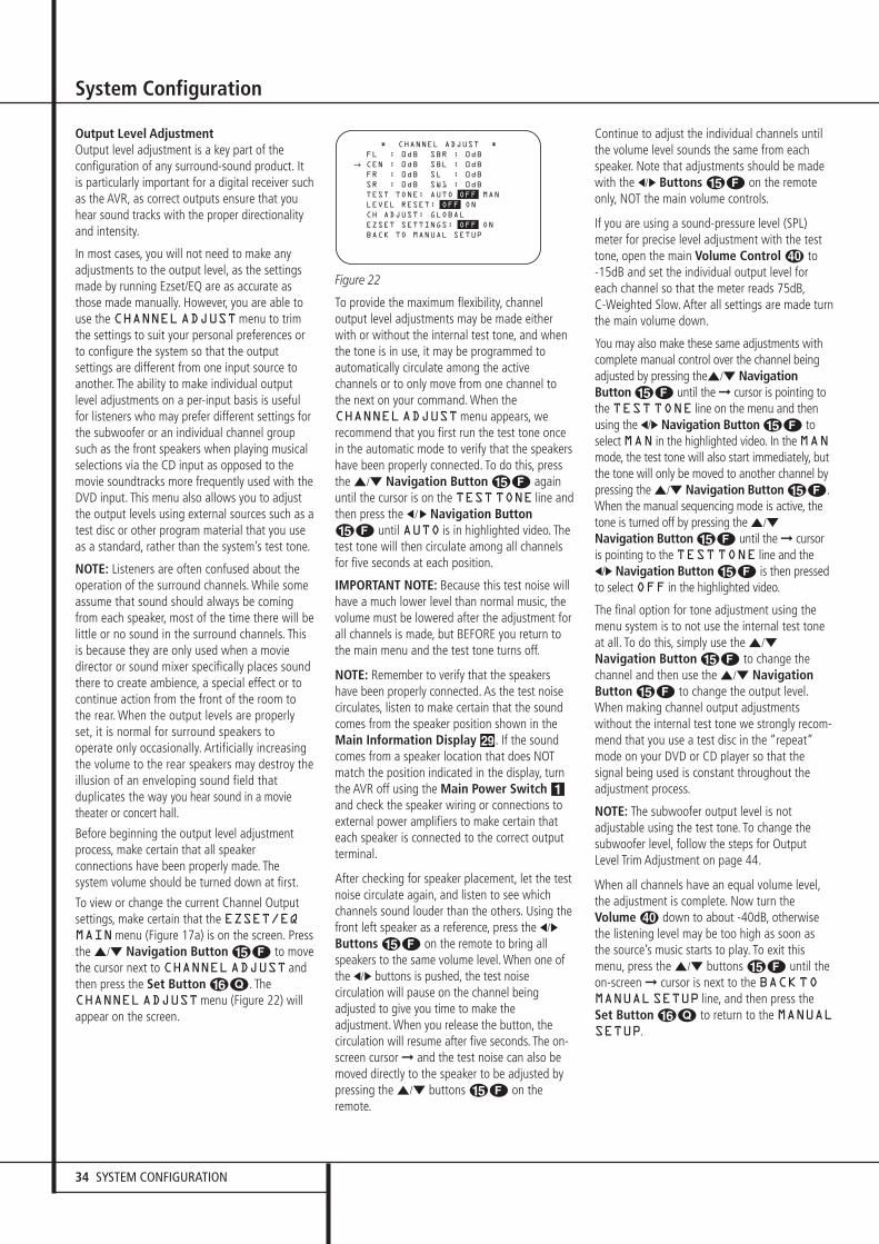
34 SYSTEM CONFIGURATION
System Configuration
Output Level AdjustmentOutput level adjustment is a key part of theconfiguration of any surround-sound product. Itis particularly important for a digital receiver suchas the AVR, as correct outputs ensure that youhear sound tracks with the proper directionalityand intensity.
In most cases, you will not need to make any adjustments to the output level, as the settings made by running Ezset/EQ are as accurate asthose made manually. However, you are able touse the CHANNELADJUSTmenu to trimthe settings to suit your personal preferences orto configure the system so that the outputsettings are different from one input source toanother. The ability to make individual outputlevel adjustments on a per-input basis is usefulfor listeners who may prefer different settings forthe subwoofer or an individual channel groupsuch as the front speakers when playing musicalselections via the CD input as opposed to themovie soundtracks more frequently used with theDVD input. This menu also allows you to adjustthe output levels using external sources such as atest disc or other program material that you useas a standard, rather than the system’s test tone.
NOTE: Listeners are often confused about theoperation of the surround channels. While someassume that sound should always be comingfrom each speaker, most of the time there will belittle or no sound in the surround channels. Thisis because they are only used when a moviedirector or sound mixer specifically places soundthere to create ambience, a special effect or tocontinue action from the front of the room tothe rear. When the output levels are properlyset, it is normal for surround speakers tooperate only occasionally. Artificially increasingthe volume to the rear speakers may destroy theillusion of an enveloping sound field thatduplicates the way you hear sound in a movietheater or concert hall.
Before beginning the output level adjustmentprocess, make certain that all speakerconnections have been properly made. Thesystem volume should be turned down at first.
To view or change the current Channel Outputsettings, make certain that the EZSET/EQMAINmenu (Figure 17a) is on the screen. Pressthe ⁄/¤ Navigation Button EF to movethe cursor next to CHANNELADJUST andthen press the Set Button FQ. TheCHANNELADJUSTmenu (Figure 22) willappear on the screen.
Figure 22
To provide the maximum flexibility, channeloutput level adjustments may be made eitherwith or without the internal test tone, and whenthe tone is in use, it may be programmed toautomatically circulate among the activechannels or to only move from one channel tothe next on your command. When theCHANNELADJUSTmenu appears, werecommend that you first run the test tone oncein the automatic mode to verify that the speakershave been properly connected. To do this, pressthe ⁄/¤ Navigation Button EF againuntil the cursor is on the TESTTONE line andthen press the ‹/› Navigation ButtonEF until AUTO is in highlighted video. Thetest tone will then circulate among all channelsfor five seconds at each position.
IMPORTANT NOTE: Because this test noise willhave a much lower level than normal music, thevolume must be lowered after the adjustment forall channels is made, but BEFORE you return tothe main menu and the test tone turns off.
NOTE: Remember to verify that the speakershave been properly connected. As the test noisecirculates, listen to make certain that the soundcomes from the speaker position shown in theMain Information Display ˜. If the soundcomes from a speaker location that does NOTmatch the position indicated in the display, turnthe AVR off using the Main Power Switch 1and check the speaker wiring or connections toexternal power amplifiers to make certain thateach speaker is connected to the correct outputterminal.
After checking for speaker placement, let the testnoise circulate again, and listen to see whichchannels sound louder than the others. Using thefront left speaker as a reference, press the ‹/›
Buttons EF on the remote to bring allspeakers to the same volume level. When one ofthe ‹/› buttons is pushed, the test noisecirculation will pause on the channel beingadjusted to give you time to make theadjustment. When you release the button, thecirculation will resume after five seconds. The on-screen cursor ➞ and the test noise can also bemoved directly to the speaker to be adjusted bypressing the ⁄/¤ buttons EF on theremote.
Continue to adjust the individual channels untilthe volume level sounds the same from eachspeaker. Note that adjustments should be madewith the ‹/› Buttons EF on the remoteonly, NOT the main volume controls.
If you are using a sound-pressure level (SPL)meter for precise level adjustment with the testtone, open the main Volume Control to -15dB and set the individual output level foreach channel so that the meter reads 75dB,C-Weighted Slow. After all settings are made turnthe main volume down.
You may also make these same adjustments withcomplete manual control over the channel beingadjusted by pressing the⁄/¤ NavigationButton EF until the ➞ cursor is pointing tothe TEST TONE line on the menu and thenusing the ‹/› Navigation Button EF toselect MAN in the highlighted video. In the MANmode, the test tone will also start immediately, butthe tone will only be moved to another channel bypressing the ⁄/¤ Navigation Button EF.When the manual sequencing mode is active, thetone is turned off by pressing the ⁄/¤
Navigation Button EF until the ➞ cursoris pointing to the TEST TONE line and the‹/› Navigation Button EF is then pressedto select OFF in the highlighted video.
The final option for tone adjustment using themenu system is to not use the internal test toneat all. To do this, simply use the ⁄/¤
Navigation Button EF to change thechannel and then use the ⁄/¤ NavigationButton EF to change the output level.When making channel output adjustmentswithout the internal test tone we strongly recom-mend that you use a test disc in the “repeat”mode on your DVD or CD player so that thesignal being used is constant throughout theadjustment process.
NOTE: The subwoofer output level is notadjustable using the test tone. To change thesubwoofer level, follow the steps for OutputLevel Trim Adjustment on page 44.
When all channels have an equal volume level,the adjustment is complete. Now turn theVolume down to about -40dB, otherwisethe listening level may be too high as soon asthe source’s music starts to play. To exit thismenu, press the ⁄/¤ buttons EF until theon-screen ➞ cursor is next to the BACKTOMANUALSETUP line, and then press theSet Button FQ to return to the MANUALSETUP.
* CHANNEL ADJUST *
FL : 0dB SBR : 0dB
CEN : 0dB SBL : 0dB
FR : 0dB SL : 0dB
SR : 0dB SW1 : 0dB
TEST TONE: AUTO OFF MAN
LEVEL RESET: OFF ON
CH ADJUST: GLOBAL
EZSET SETTINGS: OFF ON
BACK TO MANUAL SETUP
→
30362_AVR445_ENG 20/11/06 14:56 Side 34

INTRODUCTION 35
ENG
LISH
System Configuration
The output levels may also be adjusted at anytime using the remote control and semi-OSDsystem. To adjust the output levels in thisfashion, press the Test Button 8. As soon asthe button is pressed, the test tone will begin tocirculate as indicated earlier. The correct channelfrom which the test noise should be heard will beshown in the lower third of the video screen andin the Main Information Display ˜. Whilethe test noise is circulating, the proper channelposition will also be indicated in the Speaker/Channel Input Indicators Ú by a blinkingletter within the correct channel. Turn up theVolume until you can hear the test noiseclearly.
To adjust the output level, press the ⁄/¤
buttons E until the desired level is shown inthe display or on screen. Once the buttons arereleased, the test noise will begin to circulateagain in five seconds.
IMPORTANT NOTE: The Output leveladjustment made will be effective for all inputs,but only for the actual surround mode selected.To be effective for any other mode select thatmode (with any input) and repeat the leveladjustment described above. This will also allowyou to compensate level differences betweenspeakers, that may be different with eachsurround mode, or to increase or decrease thelevel of certain speakers intentionally, dependingon the surround mode selected.
Note: Output level adjustment is not availablefor the Surround Off mode, as no surroundspeakers are used (so level differences betweenthe speakers in the room cannot occur). But tocompensate level differences between stereo andother surround modes (independently from theinput selected) the outputs can be adjusted withthe Level Trim Adjustment procedure, see page44, also for the Surround Off (Stereo) modes.
In addition to the controls for selecting channelsand the test tone operation, the settings on thismenu also allow you to reset the level settings toeither the factory default of 0dB or to re-establish the settings that were entered byrunning Ezset/EQ.
To reset all channel levels to 0dB press ⁄/¤Navigation Button EF so that the cursoris pointing to the LEVELRESET line andthen press the ⁄/¤ Navigation ButtonEF once so ON appears in highlightedvideo.
To return to the settings established by Ezset/EQ,even if you have made manual changes to theoutput trims using the steps shown above, press⁄/¤ Navigation Button EF so that thecursor is pointing to the EZSETSETTINGS line and then press the ⁄/¤Navigation Button EF once so ONappears in highlighted video. Remember thatafter turning the Ezset/EQ settings back on youmust turn return to this menu line and changethe setting to OFF if you wish to make anymanual trim adjustments.
The final setting in this menu enables you tohave the output levels remain the same for allinputs or to be adjusted differently for each (orany) input. While most listeners prefer to keepthe same output levels for all sources, you maywish to raise or lower some channels, particularlythe subwoofer output for a specific source suchas a CD that is primarily used for music playback.
To enter individual settings for a specific channel,first make sure that you have either run Ezset/EQand/or made any desired manual trimadjustments to set a baseline for all channels.After that is done, press the OSD Button E toexit the menu system and then select the inputfor which you wish to enter different levelsettings by using either the Input SourceSelectors % on the front panel or the buttonson the remote that are used to select an inputsource BCD�. Next, return to theCHANNELOUTPUT submenu using thesteps outlined above.
At the CHANNELOUTPUTmenu press⁄/¤ Navigation Button EF until thecursor is pointing to the LEVELTRIM lineand then press the ⁄/¤ Navigation ButtonEF once so that INDEPENDENTappears in highlighted video. When this setting isactive you may change the channel output levelsfor any input without changing the settingspreviously established for another.
NOTE: With the default GLOBAL setting,output levels are associated with the varioussurround modes. As you spend time listening tovarious materials and selecting a variety ofsurround modes, you may wish to revisit theCHANNELADJUSTmenu to set the outputlevels.
When all changes to the Channel Output levelsand the associated level trim settings have beenmade press the ⁄/¤ Navigation ButtonEF until the cursor is on the BACKTOMANUALSETUPmenu and then pressingthe Set Button FQ so that you may makeany other adjustments to the system parameters.If the changes just made complete the manualadjustments needed, press the OSD Button Eto exit the menu system and resume normalsystem operation.
Additional Input AdjustmentsAfter one input has been adjusted for Surroundmode, digital input (if any), speaker type, andoutput levels, go back to the IN/OUTSETUP line on the MASTERMENU(Figure 7) and enter the settings for each inputthat you will use. In most cases, only the digitalinput and surround mode will be different fromone input to the next, while the speaker type,crossover frequency, Night mode and outputlevel settings will usually be the same and maybe quickly entered by entering the same dataused for the original input.
Once the settings outlined on the previous pageshave been made, the AVR is ready for operation.While there are some additional settings to bemade, these are best done after you have had anopportunity to listen to a variety of sources anddifferent kinds of program material. Theseadvanced settings are described on pages 45 to46 of this manual. In addition, any of the settingsmade in the initial configuration of the unit maybe changed at any time. As you add new ordifferent sources or speakers, or if you wish tochange a setting to better reflect your listeningtaste, simply follow the instructions for changingthe settings for that parameter as shown in thissection.
Having completed the setup and configurationprocess for your AVR, you are about toexperience the finest in music and home theaterlistening. Enjoy!
30362_AVR445_ENG 20/11/06 14:56 Side 35

36 OPERATION
Operation
Surround Mode Chart
MODE FEATURES
DOLBY DIGITAL Available only with digital input sources encoded with Dolby Digital data. It provides up to five separate main audio channels and a special dedicated Low Frequency Effects channel.
DOLBY DIGITAL EX Available when the receiver is configured for 6.1/7.1 channel operation, Dolby Digital EX is the latest version of Dolby Digital. When used with movies or other programs that have special encoding, Dolby Digital EX reproduces specially encoded soundtracks so that a full 6.1/7.1 soundfield is available. When the receiver is set for 6.1/7.1 operation and a Dolby Digital signal is present, the EX mode is automatically selected. Even if specific EX encoding is not available to provide the additional channel, the special algorithms will derive a 6.1/7.1 output.
DTS 5.1 When the speaker configuration is set for 5.1-channel operation, the DTS 5.1 mode is available when DVD, audio-only music or laserdiscs encoded with DTS data are played.DTS 5.1 provides up to five separate main audio channels and a special dedicated low-frequency channel.
DTS-ES 6.1 Matrix When the speaker configuration is set for 6.1/7.1 operation, playback of a DTS-encoded programDTS-ES 6.1 Discrete source will automatically trigger the selection of one of the two DTS-ES modes. Newer discs with
special DTS-ES discrete encoding will be decoded to provide six discrete, full-bandwidth channelsplus a separate low-frequency channel. All other DTS discs will be decoded using the DTS-ES Matrix mode, which creates a 6.1-channel sound field from the original 5.1-channel soundtrack.
DOLBY PRO LOGIC II Dolby Pro Logic II is the latest version of Dolby Laboratory’s benchmark surround technologyMOVIE that decodes full-range, discrete left, center right, right surround and left surround channels MUSIC from matrix surround encoded programs and conventional stereo sources when DOLBY PRO LOGIC an analog input or a digital input with PCM or Dolby Digital 2.0 recordings is in use. The GAME Dolby Pro Logic II Movie mode is optimized for movie soundtracks that are recorded with matrix
surround, by creating separate center, rear left and rear right signals. while the Pro Logic II Music mode should be used with musical selections that are recorded with matrix surround or even with normal stereo mode, creating separate rear left and rear right signals in any case. The Pro Logic II mode creates compelling five-channel surround sound from conventional stereo recordings. Game mode ensures that special effects are routed to the surround channels, while delivering their full impact using the subwoofer, thus fully immersing the game player in the universe of the video game.
DOLBY PRO LOGIC IIx Dolby Pro Logic IIx is the latest extension of Dolby Pro Logic II technology that creates a discrete MUSIC 6.1 and 7.1 sound field from matrix surround or two-channel stereo sources in systems MOVIE configured for surround back speakers. Both Movie and Music versions of Pro Logic IIx are GAME available. Movie, Music and Game versions of Pro Logic IIx are available. Game mode ensures that
special effects are routed to the surround channels, while delivering their full impact using the subwoofer, thus fully immersing the game player in the universe of the video game.
Logic 7 Cinema Exclusive to Harman Kardon for AV receivers, Logic 7 is an advanced mode that extracts the Logic 7 Music maximum surround information from either surround-encoded programs or conventional stereo
material. Depending on the number of speakers in use and the selection made in the SURROUNDSELECTmenu, the “5.1” versions of Logic 7 modes are available when the 5.1 option is chosen,while the “7.1” versions of Logic 7 produce a full sound field presentation, including back surround speakers when the “6.1/7.1” option is chosen. The Logic 7 C (or Cinema) mode should be used with any source that contains Dolby Surround or similar matrix encoding. Logic 7 C delivers increased center-channel intelligibility, and more accurate placement of sounds with fades and pans that are much smoother and more realistic than with former decoding techniques. The Logic 7 M or Music mode should be used with analog or PCM stereo sources. Logic 7 M enhances the listening experience by presenting a wider front soundstage and greater rear ambience. Both Logic 7 modes also direct low-frequency information to the subwoofer (if installed and configured) to deliver maximum bass impact. Logic 7 adds additional bass enhancement that circulates low frequencies in the 40Hz to 120Hz range to the front and surround speakers to deliver a less localized soundstage that appears broader and wider than when the subwoofer is the sole source of bass energy.
30362_AVR445_ENG 20/11/06 14:56 Side 36
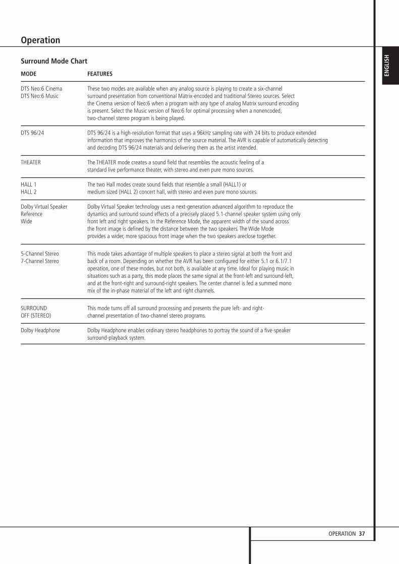
OPERATION 37
ENG
LISHSurround Mode Chart
MODE FEATURES
DTS Neo:6 Cinema These two modes are available when any analog source is playing to create a six-channel DTS Neo:6 Music surround presentation from conventional Matrix-encoded and traditional Stereo sources. Select
the Cinema version of Neo:6 when a program with any type of analog Matrix surround encoding is present. Select the Music version of Neo:6 for optimal processing when a nonencoded,two-channel stereo program is being played.
DTS 96/24 DTS 96/24 is a high-resolution format that uses a 96kHz sampling rate with 24 bits to produce extended information that improves the harmonics of the source material. The AVR is capable of automatically detecting and decoding DTS 96/24 materials and delivering them as the artist intended.
THEATER The THEATER mode creates a sound field that resembles the acoustic feeling of a standard live performance theater, with stereo and even pure mono sources.
HALL 1 The two Hall modes create sound fields that resemble a small (HALL1) or HALL 2 medium sized (HALL 2) concert hall, with stereo and even pure mono sources.
Dolby Virtual Speaker Dolby Virtual Speaker technology uses a next-generation advanced algorithm to reproduce the Reference dynamics and surround sound effects of a precisely placed 5.1-channel speaker system using only Wide front left and right speakers. In the Reference Mode, the apparent width of the sound across
the front image is defined by the distance between the two speakers. The Wide Mode provides a wider, more spacious front image when the two speakers areclose together.
5-Channel Stereo This mode takes advantage of multiple speakers to place a stereo signal at both the front and 7-Channel Stereo back of a room. Depending on whether the AVR has been configured for either 5.1 or 6.1/7.1
operation, one of these modes, but not both, is available at any time. Ideal for playing music in situations such as a party, this mode places the same signal at the front-left and surround-left,and at the front-right and surround-right speakers. The center channel is fed a summed mono mix of the in-phase material of the left and right channels.
SURROUND This mode turns off all surround processing and presents the pure left- and right- OFF (STEREO) channel presentation of two-channel stereo programs.
Dolby Headphone Dolby Headphone enables ordinary stereo headphones to portray the sound of a five-speaker surround-playback system.
Operation
30362_AVR445_ENG 20/11/06 14:56 Side 37

38 OPERATION
Operation
Basic OperationOnce you have completed the setup andconfiguration of the AVR, it is simple to operateand enjoy. The following instructions should befollowed for you to maximize your enjoyment ofyour new receiver:
Turning the AVR On or Off• When using the AVR for the first time, you mustpress the Main Power Switch 1 on the frontpanel to turn the unit on. This places the unit in aStandby mode, as indicated by the amber color ofthe Power Indicator 3. Once the unit is inStandby, you may begin a listening session bypressing the System Power Control 2 or theSource button % on the front panel or theAVR Selector 5B. Note that the PowerIndicator 3 will turn blue. This will turn the uniton and return it to the input source that was lastused. The unit may also be turned on from Standbyby pressing any of the Source Selector buttonson the remote 4567BCD orthe Source button % on the front panel.
To turn the unit off at the end of a listeningsession, simply press the System PowerControl 2 on the front panel or the PowerOff Button 3A on the remote. Power willbe shut off to any equipment plugged into therear panel Switched AC Outlets � and thePower Indicator 3 will turn orange.
When the remote is used to turn the unit “off” itis actually placing the system in a Standby mode,as indicated by the orange color of the PowerIndicator 3.
When you will be away from home for anextended period of time it is always a good ideato completely turn the unit off with the frontpanel Main Power Switch 1.
NOTE: All preset memories may be lost if theunit is left turned off with the Main PowerSwitch 1 for more than two weeks.
Using the Sleep Timer
• To program the AVR for automatic turn-off,press the Sleep Button 9 on the remote. Eachpress of the button will increase the time beforeshut down in the following sequence:
The sleep time will be displayed in the LowerDisplay Line ˜ and it will count down untilthe time has elapsed.
When the programmed sleep time has elapsed,the unit will automatically turn off (to Standbymode). Note that the front panel display will dimto one half brightness when the Sleep function isprogrammed. To cancel the Sleep function, pressand hold the Sleep Button 9 until theinformation display returns to normal brightnessand the Sleep indicator numbers disappear andthe words SLEEPOFF appear in the MainInformation Display ˜.
Source Selection• To select a source, press any of the SourceSelector buttons on the remote 467CD.
NOTE: After pressing one of the Input Selectorbuttons 4D to turn the unit on, press the AVR Selector 5B to have the remotecontrol the AVR functions.
• The input source may also be changed bypressing the front-panel Input Source Selectorbutton %. Each press of the button will movethe input selection through the list of availableinputs.
• As the input is changed, the AVR will auto-matically switch to the digital input (if selected),surround mode component video input, A/V SyncDelay and Night Mode configurations that werein effect the last time that input was used.
• The front-panel Video 4 Inputs Ô, OpticalDigital 4 Input * or the Coaxial Digital 4Input Ó may be used to connect a device suchas a video game or camcorder to your homeentertainment system on a temporary basis.When the Video 4 Inputs Ô are configured asoutputs (see page 25) you can also connect anaudio or video recorder (composite or S-Video)for recording the source selected.
• As the input source is changed, the new inputname will appear momentarily as an on-screendisplay in the lower third of the video display. Theinput name will also appear in the MainInformation Display ˜.
• When a pure audio input (CD, Tuner, Tape,6/8 Channel Input) is selected, the last videoinput used remains routed to the VideoOutputs �� (except from its own Video 1/source) and Video Monitor Output �. Thispermits simultaneous viewing and listening todifferent sources.
• When a Video source is selected, its audiosignal will be fed to the speakers and the videosignal for that input will be routed to theappropriate Monitor Output Jack � and will beviewable on a TV monitor connected to the AVR.If a component video source is connected to theDVD + or Video 1 or 2 �� ComponentInputs, it will be routed to the ComponentVideo Outputs �. Make certain that your TV isset to the proper input to view the appropriatevideo signal (composite, S-Video or componentvideo.
6-Channel/8-Channel Direct Input• There are four input choices available for usewith sources such as a DVD-Audio or SACDplayer that are connected to the 8-ChannelDirect Inputs . Select the appropriate inputaccording to the way your system and sourceequipment is configured:
• The 6 CH DIRECT input should be used whenthe SBR and SBL inputs are NOT in use and theinput source device has its own internal bassmanagement system. This input passes the inputfrom the source directly through to the volumecontrol without any analog to digital conversionand it mutes the unused input jacks to preventunwanted noise from interfering with systemperformance.
• The 6 CH DVD AUDIO input should be usedwhen the SBR and SBL inputs are NOT in use andthe input source device does NOT have its owninternal bass management system. When thisinput is in use the analog source is converted todigital so that you may use the same QuadrupleCrossover bass management options for thedirect input as you do with all other inputs. Thisinput also mutes the unused input jacks toprevent unwanted noise from interfering withsystem performance.
• The 8 CH DIRECT INPUT should be used whenan input is connected to all eight 8-ChannelDirect Inputs and when the input sourcedevice has its own internal bass managementsystem. This input passes the input from thesource directly through to the volume controlwithout any analog to digital conversion.
• The 8 CH DVD AUDIO input should be usedwhen an input is connected to all eight 8-Channel Direct Inputs and the inputsource device does NOT have its own internalbass management system. When this input is inuse the analog source is converted to digital sothat you may use the same Quadruple Crossoverbass management options for the direct input asyou do with all other inputs.
90min
80min
70min
60min
50min
40min
30min
20min
10min OFF
30362_AVR445_ENG 20/11/06 14:56 Side 38

OPERATION 39
ENG
LISHNote that when the 6-Channel or 8-Channel
Input is in use, you may not select a surroundmode, as the external decoder determines theprocessing in use. In addition, there is no signalat the record outputs or bass management whenthe 6-Channel or 8-Channel Direct Input is in useand the tone or balance controls will notfunction.
Controls and Use of Headphones• Adjust the volume to a comfortable level usingthe front panel Volume Control ı or remoteVolume Up/Down I buttons.
• To temporarily silence all speaker outputs pressthe Mute button �K. This will interrupt theoutput to all speakers and the headphone jack,but it will not affect any recording or dubbingthat may be in progress. When the system ismuted, the word MUTEwill blink in the MainInformation Display ˜. Press the Mutebutton �K again to return to normaloperation.
• During a listening session you may wish toadjust the Bass Control and Treble Control tosuit your listening tastes or room acoustics. Notethat these controls (and Balance) will not func-tion when the 6/8 channel direct input is in use.
• To set the output of the AVR so that the outputis “flat,” with the tone and balance controls de-activated, press the Tone Mode button 8�once or twice so that the words ToneOutappear momentarily in the Main InformationDisplay ˜. To return the tone controls to anactive condition, press the Tone Mode 8button once or twice so that the words ToneInmomentarily appear in the MainInformation Display ˜.
• When the tone controls are active, the amountof bass and treble boost/cut may be adjusted byfirst pressing the Tone Mode Button on thefront panel 8 or the remote � two or threetimes until the desired setting (BASSMODEor TREBLEMODE) appears in the on-screendisplay and the Lower Display Line ˜. Next,use the ⁄/¤ Navigation Button E on theremote or the ‹/› Button on the front panel7$ to change the setting as desired. The unitwill return to normal operation within fiveseconds after the setting is changed.
• For private listening, plug the 6.3 mm stereophone plug from a pair of stereo headphonesinto the front panel Headphone Jack 4.Note that when the headphone’s plug is con-nected, the speakers will automatically mute anda two-channel stereo signal will be sent to theheadphones. The Lower Display Line ˜ willread DOLBYH: BP, indicating that theheadphone output is in the Bypass mode, and toconfirm that no processing is being used.
• When the headphones are in use, you may takeadvantage of the Dolby Headphone modes tobring added spaciousness to headphone listen-ing. Press the Dolby Mode Select Button Mor the Surround Mode Group Selector 5 tocycle through the three Dolby Headphone modesto select the one that you prefer.
Surround Mode SelectionOne of the most important features of the AVR isits ability to reproduce a full multichannelsurround sound field from digital sources, analogmatrix surround encoded programs and standardstereo or even mono programs.
Selection of a surround mode is based on personaltaste, as well as the type of program sourcematerial being used. For example, CDs, motionpictures or TV programs bearing the logo of one ofthe major surround-encoding processes, such asDolby Surround should be played in either theDolby Pro Logic II Movie (with movies) or Music(with music) surround mode, with any DTS NEO:6mode or with Harman Kardon´s exclusive Logic 7Movie Mode, to create a full range 5.1 channelor (with Logic 7 and DTS NEO:6) even 7.1channel surround signal from surround encodedprograms, with a stereophonic left and right rearsignal, just as it was recorded (e.g. sound beingrecorded from left rear side will be heard fromthat side only, for more details see chart on page36).
When no rear speakers are in use, the Dolby 3Stereo mode should be selected with all surroundrecordings.
Note that when Dolby Digital 2.0 signals (e.g."D.D. 2.0" tracks from DVD), that are encodedwith Dolby Pro Logic information, are receivedvia any digital input, the Dolby Pro Logic II Moviemode will be selected automatically (in additionto the Dolby Digital mode) and will decode a fullrange 5.1 channel surround sound even fromthose recordings (see also "Dolby Digital" onpage 40).
To create wide, enveloping sound fieldenvironments and defined pans and flyovers withall analog stereo recordings select the Dolby ProLogic II Music or Emulation mode or HarmanKardon’s exclusive Logic 7 Music mode for adramatic improvement in comparison to theDolby Pro Logic ( I ) mode of former times.
NOTE: Once a program has been encoded withmatrix surround information, it retains thesurround information as long as the program isbroadcast in stereo. Thus, movies with surroundsound may be decoded via any of the analogsurround modes such as Pro Logic II Cinema,Logic 7 Cinema or DTS Neo:6 Cinema, when theyare broadcast via conventional TV stations, cable,pay-TV and satellite transmission. In addition, agrowing number of made-for-television programs,sports broadcasts, radio dramas and music CDsare also recorded in surround sound. You mayview a list of these programs at the DolbyLaboratories Web site at www.dolby.com.
Even when a program is not listed as carryingintentional surround information, you may findthat the Dolby Pro Logic II, Dolby Pro Logic IIx,DTS NEO:6 Music or Logic 7 Music or Enhancedmodes often deliver enveloping surroundpresentations through the use of the naturalsurround information present in all stereorecordings.
However, for stereo programs without anysurround information the Theater, Hall and 5/7CHStereo modes should be tried (effective particularlywith old ”extreme” stereo recordings) and formono programs, we suggest that you try theTheater or Hall modes.
Surround modes are selected using either thefront panel controls or the remote. To select anew surround mode from the front panel, firstpress the Surround Mode Group SelectorButton 5 until the desired major surroundmode group such as Dolby, DTS or Logic 7 isselected. Next, press the Surround ModeSelector Button 9 to choose the specificindividual surround mode.
To select a surround mode using the remote con-trol, press the button for the major surroundmode group that includes the mode you wish tochoose from: Dolby M, DTS Surround N,DTS Neo:6 �, Logic 7 O, Stereo � orDSP Surround A. The first press of the buttonwill show the current mode from that group if itis already in use, or the first available mode if youare currently using another mode. To cyclethrough the available modes in that group pressthe button again until the desired mode appearsin the Lower Display Line ˜ and the on-screen display.
To select from the DSP modes (Hall 1, Hall 2,Theater) press the Surround Mode SelectorA repeatedly to scroll through the list ofavailable modes.
Operation
30362_AVR445_ENG 20/11/06 14:56 Side 39

40 OPERATION
Operation
Note that the Dolby Digital or DTS modes mayonly be selected when a digital input is in use. Inaddition, when a digital source is present, theAVR will automatically select and switch to thecorrect mode (Dolby Digital or DTS), regardless ofthe mode that has been previously selected. Formore information on selecting digital sources, seethe following section of this manual.
When the 6-Channel/8-Channel direct inputs arein use there is no surround processing, as theseinputs take the analog output signals from anoptional, external DVD-Audio or SACD player, oranother source device and carry them straightthrough to the volume control.
To listen to a program in traditional two-channelstereo, using the front left and front right speakers only (plus the subwoofer, if installed andconfigured), press the Stereo Button 5�until SURROFF appears in the MainInformation Display ˜.
Digital Audio PlaybackDigital audio is a major advancement over olderanalog surround processing systems such asDolby Pro Logic. It delivers five or six discretechannels: left front, center, right front, leftsurround and right surround and with DTS ES(see below) even surround back (with identicalsignals for left and right). Each channel repro-duces full frequency range (20Hz to 20kHz) andoffers dramatically improved dynamic range andsignificant improvements to signal-to-noiseratios. In addition, digital systems have thecapability to deliver an additional channel that isspecifically devoted to low-frequency infor-mation. This is the “.1” channel referred to whenyou see these systems described as “5.1,” “6.1”or “7.1”. The bass channel is separate from theother channels, but since it is intentionallybandwidth-limited, sound designers have given itthat unique designation.
Dolby Digital Dolby Digital (originally known as AC-3®) is astandard part of DVD, and is available onspecially encoded LD discs and satellite broad-casts and it is a part of the new high-definitiontelevision (HDTV) system.
Note that an optional, external RF demodulatoris required to use the AVR to listen to the DolbyDigital sound tracks available on laser discs.Connect the RF output of the LD player to thedemodulator and then connect the digital outputof the demodulator to the Optical or Coaxialinputs ��*Ó of the AVR. No demodulatoris required for use with DVD players or DTS-encoded laser discs.
In order to provide maximum playbackcompatibility with DVDs, the AVR 445 receiverwill always default first to the playback modeembedded in a disc’s digital “flag” information.For Dolby Digital discs, the following playbackmodes are initially selected after the AVR locks tothe incoming digital audio data stream toidentify the selected:
• When a 5.1 audio stream is detected, theDolby Digital 5.1 format will be selected,regardless of the number of speakers in yoursystem, in compliance with Dolby Laboratorieslicensing requirements.
• When a disc with the Dolby Digital EX formatflag is played, your system will automaticallyswitch to the EX mode when seven mainchannel speakers are available.
• When a disc with Dolby Digital data, but only2.0 audio is detected, the default mode isDolby Digital with Pro Logic II post-processingwhen you have a 5.1 speaker system, or Dolby Digital with Pro Logic IIx post-processingwhen you have a 7.1 speaker system.
• Depending on the number of speaker channelsavailable in your system, once the AVR locks tothe digital signal, you may select any surroundmode or post-processing option that isavailable, based on the incoming data stream’spossible restrictions and the number ofspeakers in your system. For example, when a5.1 or 2.0 audio stream is in use, you mayselect alternate postprocessing such as Logic 7/7-Channel Movie Mode post-processing to create the rear surrounds in 7.1 speaker systems.
DTS
DTS is another digital audio system that iscapable of delivering 5.1, 6.1 or 7.1 audio.Although both DTS and Dolby Digital are digital,they use different methods of encoding thesignals, and thus they require different decodingcircuits to convert the digital signals back toanalog.
DTS-encoded sound tracks are available on selectDVD and LD discs, as well as on special audio-only DTS CDs. You may use any LD, DVD or CDplayer equipped with a digital output to playDTS-encoded special audio-only CDs with theAVR, but DTS-LDs can be played on LD playersand DTS-DVDs on DVD players only. All that isrequired is to connect the player’s digital outputto either the Optical or Coaxial input on therear panel �� or front panel *Ó.
In order to listen to DVDs encoded with DTSsound tracks, the DVD player must be compatiblewith the DTS signal as indicated by a DTS logoon the player’s front panel. Note that early DVDplayers may not be able to play DTS- encodedDVDs. This does not indicate a problem with the
AVR, as some players cannot pass the DTS signalthrough to the digital outputs. If you are in doubtas to the capability of your DVD player to handleDTS DVDs, consult the player’s owner’s manual.
Please note that some DVD players are shippedwith their output set for Dolby Digital only. Toinsure that DTS data is being sent to the AVR,please check the setup menu system on yourDVD player to make certain that DTS data outputis enabled.
PCM Audio PlaybackPCM (Pulse Code Modulation) is the non-compressed digital audio system used forcompact discs, Non-Dolby Digital/DTS Laserdiscsand some special PCM encoded DVDs. The digitalcircuits in the AVR are capable of high qualitydigital-to-analog decoding, and they may beconnected directly to the digital audio output ofyour CD/DVD or LD player (LD only for PCM orDTS programs, for Dolby Digital laser discs an RFadapter is needed, see ”Dolby Digital” above).
Connections may be made to either the Opticalor Coaxial inputs �� on the rear panel or thefront panel Digital Inputs *Ó.
To listen to a PCM digital source, first select theinput for the desired source (e.g., CD) to feed itsvideo signal (if any) to the TV monitor and toprovide its analog audio signal for recording.Next press the Digital Select button ÛGand then use the ⁄ /¤ buttons E on theremote, or the Selector buttons7$ on thefront panel, until the desired choice appears in theLower Display Line ˜, then press the Setbutton @F to confirm the choice.
In most cases this will be 48KHZ, though inthe case of specially mastered, high-resolutionaudio discs you will see a 96KHZ indication.
The PCM48KHZ indication will also appearwhen modes or inputs are changed for analogsources. In those cases the system is telling youthe sampling frequency used internally at theoutput of the analog-to-digital converters thatchange the incoming signal from a VCR, tapedeck, the tuner, or other ana-log source todigital.
During PCM playback the unit automatically willturn to the default surround mode or to theLOGIC7 mode but you also may select anysurround mode except Dolby Digital or DTS.
30362_AVR445_ENG 20/11/06 14:56 Side 40
OPERATION 41
ENG
LISHSelecting a Digital Source
To utilize either digital mode you must have properly connected a digital source to the AVR.Connect the digital outputs from DVD players,HDTV receivers, satellite systems or CD players tothe Optical or Coaxial inputs on the rear orfront panel ��*Ó. In order to provide abackup signal and a source for analog stereorecording, the analog outputs provided on digitalsource equipment should also be connected totheir appropriate inputs on the AVR rear panel(e.g., connect the analog stereo audio outputfrom a DVD to the DVD Audio inputs onthe rear panel when you connect the source’sdigital outputs).
To select a digital source such as DVD, first selectits input using the remote or front panel InputSelector 4% as outlined in this manual inorder to feed its video signal (if any) to the TVmonitor and to provide its analog audio signalfor recording. When the digital input associatedwith the input selected (e.g. “DVD”) is notselected automatically (due to the input settingsmade earlier during the system configuration, seepage 24), select the digital source by pressingthe Digital Input Selector button GÛ andthen using the ⁄/¤ buttons E on the remoteor the Selector buttons7$ on the frontpanel to choose any of the OPTICAL orCOAXIAL inputs, as they appear in theUpper Display Line ˜ or on-screen display.
When the digital source is playing, the AVR willautomatically detect whether it is a multichannelDolby Digital or DTS source, MP3 or conventionalPCM signal, which is the standard output fromCD players.
Note that a digital input (e.g. coaxial) remainsassociated with any analog input (e.g. DVD) assoon as it is selected, thus the digital input neednot be re-selected each time the appropriateinput choice (e.g. DVD) is made.
Digital Bitstream IndicatorsWhen a digital source is playing, the AVR sensesthe type of bitstream data that is present. Usingthis information, the correct surround mode willautomatically be selected. For example, DTS bit-streams will cause the unit to switch to DTSdecoding, and Dolby Digital bitstreams will enableDolby Digital decoding. When the unit sensesPCM data, from CDs and LDs and some musicDVDs or certain tracks on normal DVDs, it willallow the appropriate surround mode to beselected manually. Since the range of availablesurround modes depends on the type of digitaldata that is present, the AVR uses a variety ofindicators to let you know what type of signal ispresent. This will help you to understand thechoice of modes and the input channels recordedon the disc.
When a digital source is playing, the AVR willdisplay a variety of messages to indicate the typeof bitstream received. These messages willappear shortly after an input or surround mode ischanged, and will remain in the Main Infor-mation Display ˜ for about five secondsbefore the display returns to the normal surroundmode indication.
For Dolby Digital and DTS sources, a three digitindication will appear, showing the number ofchannels present in the data. An example of thistype of display is 3/2/.1.
The first number indicates how many discretefront channel signals are present.
• A 3 tells you that separate front left, centerand front right signals are available. This will bedisplayed for Dolby Digital 5.1 and DTS 5.1programs.
• A 2 tells you that separate front left and rightsignals are available, but there is no discretecenter channel signal. This will be displayed forDolby Digital bit streams that have stereoprogram material.
• A 1 tells you that there is only a mono channelavailable in the Dolby Digital bitstream.
The middle number indicates how many discretesurround channel signals are present.
• A "3" tells you that separate, discrete leftsurround, center surround and right surroundsignals are present. This is available only ondiscs with DTS-ES digital audio.
• A 2 tells you that separate surround left andright signals are available. This will bedisplayed for Dolby Digital 5.1 and DTS 5.1programs.
• A 1 tells you that there is only a single,surround encoded surround channel. This willappear for Dolby Digital bit streams that havematrix encoding.
• A 0 indicates that there is no surround channelinformation. This will be displayed for two-channel stereo programs.
The last number indicates if there is a discreteLow Frequency Effects (LFE) channel. This is the“.1” in the common abbreviation of “5.1” soundand it is a special channel that contains only bassfrequencies.
• A .1 tells you that an LFE channel is present.This will be displayed for Dolby Digital 5.1 andDTS 5.1 programs, as available.
• A 0 indicates that there is no LFE channelinformation available. However, even whenthere is no dedicated LFE channel, lowfrequency sound will be present at thesubwoofer output when the speakerconfiguration is set to show the presence ofsubwoofer.
• The information in the right side of the displaywill tell you if the digital audio data contains aspecial flag signal that will automaticallyactivate the appropriate 6.1 or 7.1 mode. Thiswill be shown as EX-ON or EX-OFF for DolbyDigital bitstreams and ES-ON or ES-OFF forDTS bitstreams.
When Dolby Digital 3/2/.1 or DTS 3/2/.1 signalsare being played, the AVR will automaticallyswitch to the proper surround mode, and noother processing may be selected. When a DolbyDigital signal with a 3/1/0 or 2/0/0 signal isdetected you may select any of the Dolbysurround modes.
It is always a good idea to check the readout forthe channel data to make certain that it matchesthe audio logo information shown on the back ofa DVD package. In some cases you will seeindication for “2/0/0” even when the disccontains a full 5.1, or 3/2/.1 signal. When thishappens, check the audio output settings foryour DVD player or the audio menu selections forthe specific disc being played to make certainthat the player is sending the correct signal tothe AVR.
USB PlaybackThe AVR 445 is among the very few A/V receiverscapable of direct connection to a computer foraudio playback. Once the AVR is connected,audio streams and playback are possible throughyour AVR, with all the power and performance ofthe high-current amplifier, your own speakers,and the enhanced multichannel playback madepossible through the use of Logic 7, Dolby Pro Logic II/IIx or DTS Neo:6 processing.
The AVR’s USB connectivity may be used withPC-compatible computers running eitherMicrosoft® Windows® 2000 with Service Pack 4or higher installed, or Windows XP® or WindowsXP Media Center Edition with Service Pack 1 orhigher installed. Connect one of the availableUSB jacks on your computer or a USB hub to theUSB Jack � on the AVR using a cable with astandard USB plug on one side and a USB “MiniB” plug on the other side.
Operation
30362_AVR445_ENG 20/11/06 14:56 Side 41
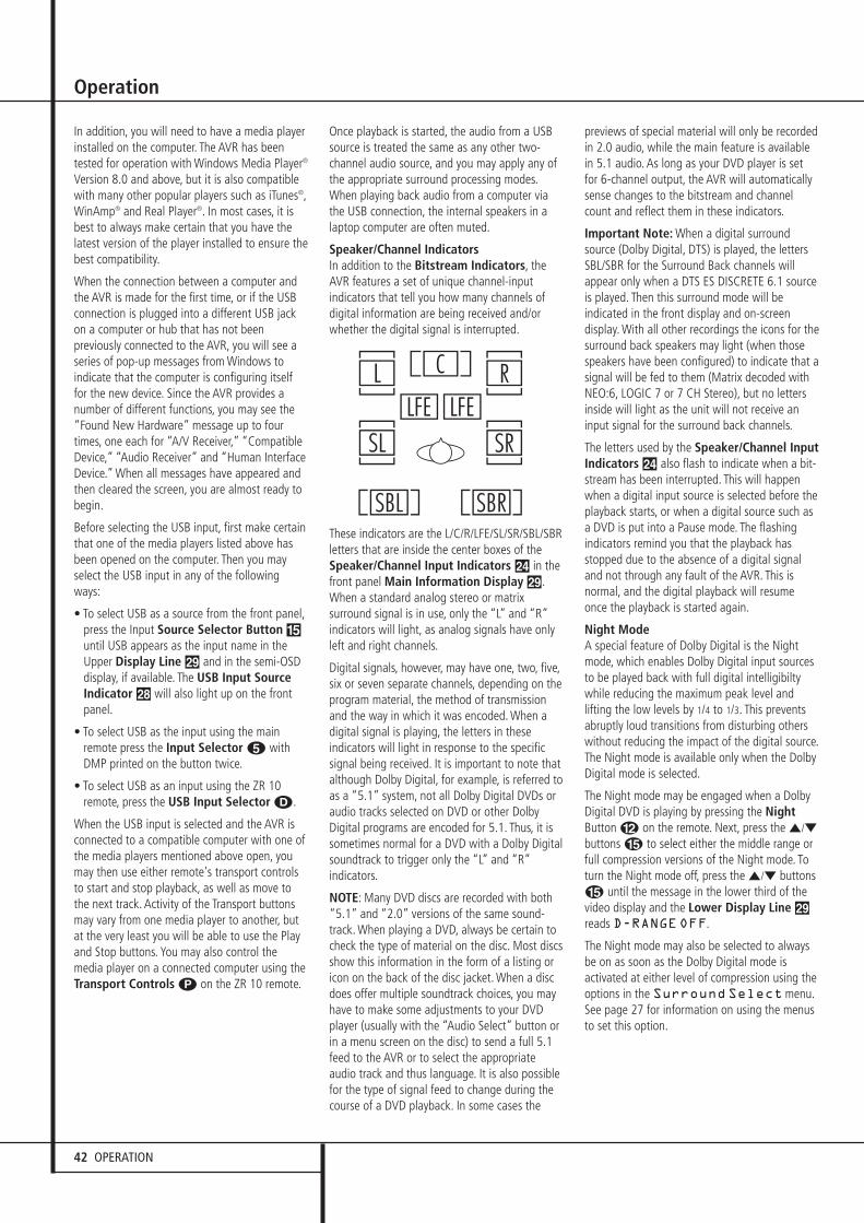
42 OPERATION
Operation
In addition, you will need to have a media playerinstalled on the computer. The AVR has beentested for operation with Windows Media Player®
Version 8.0 and above, but it is also compatiblewith many other popular players such as iTunes®,WinAmp® and Real Player®. In most cases, it isbest to always make certain that you have thelatest version of the player installed to ensure thebest compatibility.
When the connection between a computer andthe AVR is made for the first time, or if the USBconnection is plugged into a different USB jackon a computer or hub that has not beenpreviously connected to the AVR, you will see aseries of pop-up messages from Windows toindicate that the computer is configuring itselffor the new device. Since the AVR provides anumber of different functions, you may see the“Found New Hardware” message up to fourtimes, one each for “A/V Receiver,” “CompatibleDevice,” “Audio Receiver” and “Human InterfaceDevice.” When all messages have appeared andthen cleared the screen, you are almost ready tobegin.
Before selecting the USB input, first make certain that one of the media players listed above hasbeen opened on the computer. Then you mayselect the USB input in any of the followingways:
• To select USB as a source from the front panel,press the Input Source Selector Button %until USB appears as the input name in theUpper Display Line ˜ and in the semi-OSDdisplay, if available. The USB Input SourceIndicator ˆ will also light up on the frontpanel.
• To select USB as the input using the mainremote press the Input Selector 4 withDMP printed on the button twice.
• To select USB as an input using the ZR 10remote, press the USB Input Selector D.
When the USB input is selected and the AVR isconnected to a compatible computer with one ofthe media players mentioned above open, youmay then use either remote's transport controlsto start and stop playback, as well as move tothe next track. Activity of the Transport buttonsmay vary from one media player to another, butat the very least you will be able to use the Playand Stop buttons. You may also control themedia player on a connected computer using theTransport Controls P on the ZR 10 remote.
Once playback is started, the audio from a USBsource is treated the same as any other two-channel audio source, and you may apply any ofthe appropriate surround processing modes.When playing back audio from a computer viathe USB connection, the internal speakers in alaptop computer are often muted.
Speaker/Channel IndicatorsIn addition to the Bitstream Indicators, the AVR features a set of unique channel-inputindicators that tell you how many channels ofdigital information are being received and/orwhether the digital signal is interrupted.
These indicators are the L/C/R/LFE/SL/SR/SBL/SBRletters that are inside the center boxes of theSpeaker/Channel Input Indicators Ú in thefront panel Main Information Display ˜.When a standard analog stereo or matrix surround signal is in use, only the “L” and “R”indicators will light, as analog signals have onlyleft and right channels.
Digital signals, however, may have one, two, five,six or seven separate channels, depending on theprogram material, the method of transmissionand the way in which it was encoded. When adigital signal is playing, the letters in these indicators will light in response to the specificsignal being received. It is important to note thatalthough Dolby Digital, for example, is referred toas a “5.1” system, not all Dolby Digital DVDs oraudio tracks selected on DVD or other DolbyDigital programs are encoded for 5.1. Thus, it issometimes normal for a DVD with a Dolby Digitalsoundtrack to trigger only the “L” and “R”indicators.
NOTE: Many DVD discs are recorded with both“5.1” and “2.0” versions of the same sound-track. When playing a DVD, always be certain tocheck the type of material on the disc. Most discsshow this information in the form of a listing oricon on the back of the disc jacket. When a discdoes offer multiple soundtrack choices, you mayhave to make some adjustments to your DVDplayer (usually with the “Audio Select” button orin a menu screen on the disc) to send a full 5.1feed to the AVR or to select the appropriateaudio track and thus language. It is also possiblefor the type of signal feed to change during thecourse of a DVD playback. In some cases the
previews of special material will only be recordedin 2.0 audio, while the main feature is availablein 5.1 audio. As long as your DVD player is setfor 6-channel output, the AVR will automaticallysense changes to the bitstream and channelcount and reflect them in these indicators.
Important Note: When a digital surroundsource (Dolby Digital, DTS) is played, the lettersSBL/SBR for the Surround Back channels willappear only when a DTS ES DISCRETE 6.1 sourceis played. Then this surround mode will beindicated in the front display and on-screendisplay. With all other recordings the icons for thesurround back speakers may light (when thosespeakers have been configured) to indicate that asignal will be fed to them (Matrix decoded withNEO:6, LOGIC 7 or 7 CH Stereo), but no lettersinside will light as the unit will not receive aninput signal for the surround back channels.
The letters used by the Speaker/Channel InputIndicators Ú also flash to indicate when a bit-stream has been interrupted. This will happenwhen a digital input source is selected before theplayback starts, or when a digital source such asa DVD is put into a Pause mode. The flashingindicators remind you that the playback hasstopped due to the absence of a digital signaland not through any fault of the AVR. This isnormal, and the digital playback will resumeonce the playback is started again.
Night Mode A special feature of Dolby Digital is the Nightmode, which enables Dolby Digital input sourcesto be played back with full digital intelligibiltywhile reducing the maximum peak level andlifting the low levels by 1/4 to 1/3. This preventsabruptly loud transitions from disturbing otherswithout reducing the impact of the digital source.The Night mode is available only when the DolbyDigital mode is selected.
The Night mode may be engaged when a DolbyDigital DVD is playing by pressing the NightButton B on the remote. Next, press the ⁄/¤
buttons E to select either the middle range orfull compression versions of the Night mode. Toturn the Night mode off, press the ⁄/¤ buttonsE until the message in the lower third of thevideo display and the Lower Display Line ˜reads D-RANGEOFF.
The Night mode may also be selected to alwaysbe on as soon as the Dolby Digital mode is activated at either level of compression using theoptions in the SurroundSelectmenu.See page 27 for information on using the menusto set this option.
30362_AVR445_ENG 20/11/06 14:56 Side 42

OPERATION 43
ENG
LISHIMPORTANT NOTES ON DIGITAL PLAYBACK:
• When the digital playback source is stopped, orin a pause, fast forward or chapter search mode,the digital audio data will momentarily stop, andthe channel position letters inside the Speaker/Channel Indicators Ú will flash. This is nor-mal and does not indicate a problem with eitherthe AVR or the source machine. The AVR willreturn to digital playback as soon as the data isavailable and when the machine is in a standardplay mode.
• Although the AVR will decode virtually all DVDmovies, CDs and HDTV sources, it is possible thatsome future digital sources may not be compatiblewith the AVR.
• Note that not all digitally encoded programsand not all audio tracks on a DVD contain full5.1 or 6.1 channel audio. Consult the programguide that accompanies the DVD or laser disc todetermine which type of audio has beenrecorded on the disc. The AVR will automaticallysense the type of digital surround encoding used,indicate it in the Channel Input Indicators Úand adjust to accommodate it.
• When a Dolby Digital or DTS source is playing,you normally may not be able to select some ofthe analog surround modes such as Dolby ProLogic II, Dolby 3 Stereo, Hall, Theater, 5CH/7CHStereo or Logic 7, except with specific DolbyDigital 2.0 recordings that can be played withthe Pro Logic II modes too (see page 40).
• When a digital source is playing, it is possibleto make an analog recording using the Tape �or Video 1 or Video 2 or "& record outputs,even if the source is connected to any digitalinput of the AVR only, as long as "Surround Off"mode is selected (possible with a PCM sourceonly). But the analog two channel signal, even ofa Dolby Digital (not DTS) source, the ”Downmix”to Stereo or Dolby Surround, can be recorded byconnecting its analog audio outputs to theappropriate analog inputs (e.g. DVD) of the AVR.Additionally, the digital signals will be passedthrough to the Digital Audio Outputs �.
Using The AVR 445 is equipped for use with HarmanKardon’s optional iPod dockingstation.
When The Bridge is connected to the AVR and aniPod properly docked, you may use either remoteto control the iPod for audio playback, whileusing the front-panel display and on-screensemi-OSD messages to help you locate tracks orview information about the track being played. Inaddition, connecting an iPod to the AVR throughThe Bridge also charges the iPod’s battery.
Using the DMPAUTOPOWERmenu option,as described on page 46, you may even have theAVR automatically turn on with your iPod as aplayback source whenever the iPod is turned on.
To select The Bridge as the AVR’s input source:
• From the front panel, press the Input SourceSelector 7 on the front panel as needed.
• From the main remote, press the Input DMPSelector 3.
• From the ZR 10 remote, press the /DMPSelector �.
When The Bridge is connected and a compatibleiPod properly docked, the iPod’s menu will bereplaced with “harman/kardon” at the top of theiPod’s screen and the front panel display andsemi-OSD message will show messages that willguide you through the menu and contentselection. If the Lower Display Line ˜ showsan UNPLUGGED… message, please check tosee that the correct iPod adapter is used in TheBridge and that the iPod is properly seated.
The AVR’s front-panel controls may also be usedto access a limited number of iPod functions.Press the Tuner Mode Button ! to play orpause the current track. The Tuning Selector) may be used to search in reverse (left side ofbutton) or forward (right side of button) throughthe tracks. Press the Tuner Band Selector !to call up the iPod’s menu. Press the PresetStation Selectors # to scroll and the SetButton @ to select. For complete informationon using the remote or front-panel controls tooperate an iPod, see the instructions that areincluded with The Bridge.
Tape RecordingIn normal operation, the audio or video sourceselected for listening through the AVR is sent tothe record outputs. This means that any programyou are watching or listening to may be recordedsimply by placing machines connected to the out-puts for Tape Outputs � or Video 1 or 2Outputs ��"& in the record mode.
When a digital audio recorder is connected toany of the Digital Audio Outputs �, you areable to record the digital signal using a CD-R,MiniDisc or other digital recording system.Note that all digital signals will be passedthrough to both, coaxial and optical, digital outputs simultanously, no matter which kind ofdigital input was selected.
Front Panel In/OutputsIn addition to the rear panel digital outputs, theAVR offers Harman Kardon’s exclusiveconfigurable front panel output jack feature.For easy connection of portable devices, you mayswitch the front panel Video 4 jack Ô from aninput to an output by following these steps:
1. Press the OSD button L to view the MASTERMENU (Figure 7).
2. Press the Set button F to enter theIN/OUTSETUPmenu (Figure 8).
3. Press the ¤ button E so that the on-screen➞ cursor is next to VIDEO4.
4. Press either of the ‹ /› buttons E so thatthe word OUT is highlighted.
5. Press the OSD button L to exit the menusand return to normal operation.
Note that once the setting is made, theappropriate Input/Output Status Indicator( will turn red, indicating that the selectedanalog jacks are now an output, instead of in thedefault setting as an input. Once changed to anoutput, the setting will remain as long as theAVR is turned on, unless the setting is changed inthe OSD menu system, as described above. Note,however, that once the AVR is turned off, thesetting is cancelled. When the unit is turned onagain, the front panel jacks will return to theirnormal default setting as an input. If you wish touse the jacks as an output at a future time, thesetting must be changed again using the OSDmenu system, as described above.
NOTES:• To make an analog recording from a digitalsource is possible, but only from a PCM source(not Dolby Digital or DTS) and correctly only with"Surround Off" mode (with any Surround modeonly the L/R front signals will be fed to the recordoutputs).
The Bridge TM
Operation
30362_AVR445_ENG 20/11/06 14:56 Side 43
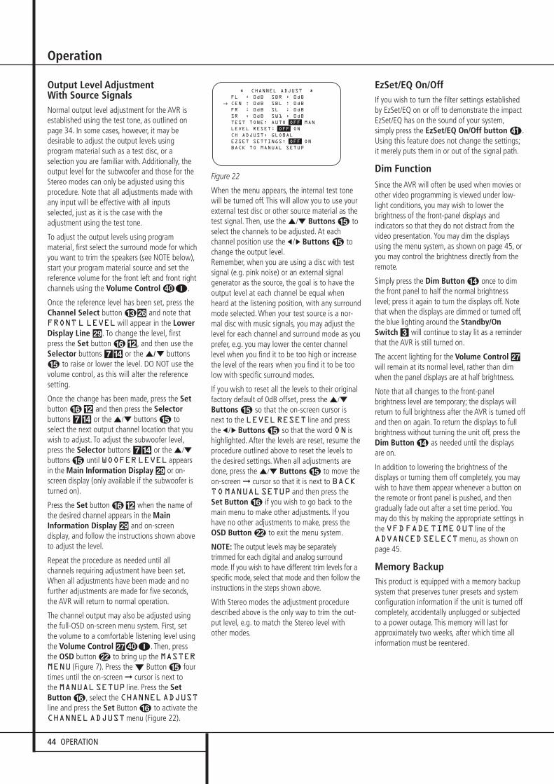
44 OPERATION
Operation
Output Level Adjustment With Source Signals Normal output level adjustment for the AVR isestablished using the test tone, as outlined onpage 34. In some cases, however, it may bedesirable to adjust the output levels usingprogram material such as a test disc, or aselection you are familiar with. Additionally, theoutput level for the subwoofer and those for theStereo modes can only be adjusted using thisprocedure. Note that all adjustments made withany input will be effective with all inputsselected, just as it is the case with theadjustment using the test tone.
To adjust the output levels using programmaterial, first select the surround mode for whichyou want to trim the speakers (see NOTE below),start your program material source and set the reference volume for the front left and front rightchannels using the Volume Control I.
Once the reference level has been set, press theChannel Select button CÙ and note thatFRONT L LEVELwill appear in the LowerDisplay Line ˜. To change the level, firstpress the Set button F@, and then use theSelector buttons 7$ or the ⁄/¤ buttonsE to raise or lower the level. DO NOT use thevolume control, as this will alter the referencesetting.
Once the change has been made, press the Setbutton F@ and then press the Selectorbuttons 7$ or the ⁄/¤ buttons E toselect the next output channel location that youwish to adjust. To adjust the subwoofer level,press the Selector buttons 7$ or the ⁄/¤
buttons E until WOOFERLEVEL appearsin the Main Information Display ˜ or on-screen display (only available if the subwoofer isturned on).
Press the Set button F@ when the name ofthe desired channel appears in the MainInformation Display ˜ and on-screen display, and follow the instructions shown aboveto adjust the level.
Repeat the procedure as needed until allchannels requiring adjustment have been set.When all adjustments have been made and nofurther adjustments are made for five seconds,the AVR will return to normal operation.
The channel output may also be adjusted usingthe full-OSD on-screen menu system. First, setthe volume to a comfortable listening level usingthe Volume Control ı I. Then, pressthe OSD button L to bring up the MASTERMENU (Figure 7). Press the ¤ Button E fourtimes until the on-screen ➞ cursor is next to the MANUALSETUP line. Press the SetButton F, select the CHANNELADJUSTline and press the Set Button F to activate theCHANNELADJUSTmenu (Figure 22).
Figure 22
When the menu appears, the internal test tonewill be turned off. This will allow you to use yourexternal test disc or other source material as thetest signal. Then, use the ⁄/¤ Buttons E toselect the channels to be adjusted. At each channel position use the ‹ /› Buttons E tochange the output level.Remember, when you are using a disc with testsignal (e.g. pink noise) or an external signalgenerator as the source, the goal is to have theoutput level at each channel be equal whenheard at the listening position, with any surroundmode selected. When your test source is a nor-mal disc with music signals, you may adjust thelevel for each channel and surround mode as youprefer, e.g. you may lower the center channellevel when you find it to be too high or increasethe level of the rears when you find it to be toolow with specific surround modes.
If you wish to reset all the levels to their originalfactory default of 0dB offset, press the ⁄/¤
Buttons E so that the on-screen cursor isnext to the LEVELRESET line and pressthe ‹ /› Buttons E so that the word ON ishighlighted. After the levels are reset, resume theprocedure outlined above to reset the levels tothe desired settings. When all adjustments aredone, press the ⁄/¤ Buttons E to move theon-screen ➞ cursor so that it is next to BACKTOMANUALSETUP and then press theSet Button F if you wish to go back to themain menu to make other adjustments. If youhave no other adjustments to make, press theOSD Button L to exit the menu system.
NOTE: The output levels may be separatelytrimmed for each digital and analog surroundmode. If you wish to have different trim levels for aspecific mode, select that mode and then follow theinstructions in the steps shown above.
With Stereo modes the adjustment proceduredescribed above is the only way to trim the out-put level, e.g. to match the Stereo level withother modes.
EzSet/EQ On/OffIf you wish to turn the filter settings establishedby EzSet/EQ on or off to demonstrate the impactEzSet/EQ has on the sound of your system,simply press the EzSet/EQ On/Off button �.Using this feature does not change the settings;it merely puts them in or out of the signal path.
Dim Function
Since the AVR will often be used when movies orother video programming is viewed under low-light conditions, you may wish to lower thebrightness of the front-panel displays andindicators so that they do not distract from thevideo presentation. You may dim the displaysusing the menu system, as shown on page 45, oryou may control the brightness directly from theremote.
Simply press the Dim Button D once to dimthe front panel to half the normal brightnesslevel; press it again to turn the displays off. Notethat when the displays are dimmed or turned off,the blue lighting around the Standby/OnSwitch 3 will continue to stay lit as a reminderthat the AVR is still turned on.
The accent lighting for the Volume Control ıwill remain at its normal level, rather than dimwhen the panel displays are at half brightness.
Note that all changes to the front-panelbrightness level are temporary; the displays willreturn to full brightness after the AVR is turned offand then on again. To return the displays to fullbrightness without turning the unit off, press theDim Button D as needed until the displaysare on.
In addition to lowering the brightness of thedisplays or turning them off completely, you maywish to have them appear whenever a button onthe remote or front panel is pushed, and thengradually fade out after a set time period. Youmay do this by making the appropriate settings inthe VFDFADETIMEOUT line of theADVANCEDSELECTmenu, as shown onpage 45.
Memory BackupThis product is equipped with a memory backupsystem that preserves tuner presets and systemconfiguration information if the unit is turned offcompletely, accidentally unplugged or subjectedto a power outage. This memory will last forapproximately two weeks, after which time allinformation must be reentered.
* CHANNEL ADJUST *
FL : 0dB SBR : 0dB
CEN : 0dB SBL : 0dB
FR : 0dB SL : 0dB
SR : 0dB SW1 : 0dB
TEST TONE: AUTO OFF MAN
LEVEL RESET: OFF ON
CH ADJUST: GLOBAL
EZSET SETTINGS: OFF ON
BACK TO MANUAL SETUP
→
30362_AVR445_ENG 20/11/06 14:56 Side 44
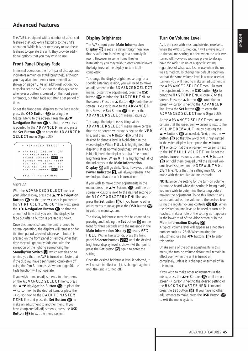
ADVANCED FEATURES 45
ENG
LISHThe AVR is equipped with a number of advanced
features that add extra flexibility to the unit’soperation. While it is not necessary to use thesefeatures to operate the unit, they provide addi-tional options that you may wish to use.
Front-Panel-Display FadeIn normal operation, the front-panel displays andindicators remain on at full brightness, althoughyou may also dim them or turn them off asshown on page 46. As an additional option, youmay also set the AVR so that the displays are onwhenever a button is pressed on the front panelor remote, but then fade out after a set period oftime.
To set the front-panel displays to the Fade mode,press the OSD Button L to bring the Master Menu to the screen. Press the ⁄/¤
Navigation Button E so that the ➞ cursoris pointed to the ADVANCED line, and pressthe Set Button F to enter the ADVANCEDSELECTmenu (Figure 23).
Figure 23
With the ADVANCEDSELECTmenu onyour video display, press the ⁄/¤ NavigationButton E so that the ➞ cursor is pointed tothe VFDFADETIMEOUT line. Next, pressthe ‹ /› Navigation Button E so that theamount of time that you wish the displays tofade out after a button is pressed is shown.
Once this time is set and the unit returned tonormal operation, the displays will remain on forthe time period selected whenever a button ispressed on the front panel or remote. After thattime they will gradually fade out, with theexception of the lighting surrounding theStandby/On Switch 3, which remains on toremind you that the AVR is turned on. Note thatif the displays have been turned completely offusing the Dim Button, as shown on page 46, theFade function will not operate.
If you wish to make adjustments to other itemson the ADVANCEDSELECTmenu, pressthe ⁄/¤ Navigation Button E to place the➞ cursor next to the desired item, or place the➞ cursor next to the BACKTOMASTERMENU line and press the Set Button F tomake an adjustment to another menu. If youhave completed all adjustments, press the OSDButton L to exit the menu system.
Display BrightnessThe AVR’s front panel Main InformationDisplay ˜ is set at a default brightness levelthat is sufficient for viewing in a normally litroom. However, in some home theaterinstallations, you may wish to occasionally lowerthe brightness of the display, or turn it offcompletely.
To change the display brightness setting for aspecific listening session, you will need to makean adjustment in the ADVANCEDSELECTmenu. To start the adjustment, press the OSDbutton L to bring the MASTERMENU tothe screen. Press the ⁄ Button E, until the on-screen ➞ cursor is next to the ADVANCEDline. Press the Set Button F to enter theADVANCEDSELECTmenu (Figure 23).
To change the brightness setting, at theADVANCEDSELECTmenu, make certainthat the on-screen ➞ cursor is next to the VFDline, and press the › Button E until thedesired brightness level is highlighted in thevideo display. When FULL is highlighted, thedisplay is at its normal brightness. When HALFis highlighted, the display is at half the normalbrightness level. When OFF is highlighted, all ofthe indicators in the Main InformationDisplay ˜ will go dark. Note, however, that thePower Indicator 3, will always remain lit toremind you that the unit is turned on.
If you wish to make other adjustments in themenu, press the ⁄/¤ Buttons E until the on-screen ➞ cursor is next to the desired setting orthe BACKTOMASTERMENU line andpress the Set button F. If you have no otheradjustments to make, press the OSD Button Lto exit the menu system.
The display brightness may also be changed bypressing and holding the Set button @ on thefront for three seconds until the message in theMain Information Display ˜ reads VFDFULL. Within five seconds, press the frontpanel Selector buttons 7$ until the desiredbrightness display level is shown. At that point,press the Set button @ again to enter thesetting.
Once the desired brightness level is selected, itwill remain in effect until it is changed again oruntil the unit is turned off.
Turn On Volume LevelAs is the case with most audio/video receivers,when the AVR is turned on, it will always returnto the volume setting in effect when the unit wasturned off. However, you may prefer to alwayshave the AVR turn on at a specific setting,regardless of what was last in use when the unitwas turned off. To change the default conditionso that the same volume level is always used atturn-on, you will need to make an adjustment inthe ADVANCEDSELECTmenu. To startthe adjustment, press the OSD button L tobring the MASTERMENU (Figure 7) to thescreen. Press the ⁄ button E, until the on-screen ➞ cursor is next to the ADVANCEDline. Press the Set button F to enter theADVANCEDSELECTmenu (Figure 23).
At the ADVANCEDSELECTmenu makecertain that the on-screen ➞ cursor is next to theVOLUMEDEFAULT line by pressing the⁄/¤ buttons E as needed. Next, press the ➞button E so that the word ON is highlightedin the video display. Next, press the ¤ buttonE once so that the on-screen ➞ cursor is nextto the DEFAULTVOLSET line. To set thedesired turn-on volume, press the ‹ /› buttonsE or hold them pressed until the desired vol-ume level is shown on the DEFAULTVOLSET line. Note that this setting may NOT bemade with the regular volume controls.
NOTE: Since the setting for the turn-on volumecannot be heard while the setting is being made,you may wish to determine the setting beforemaking the adjustment. To do this, listen to anysource and adjust the volume to the desired levelusing the regular volume controls I. Whenthe desired volume level to be used at turn-on isreached, make a note of the setting as it appearsin the lower third of the video screen or in theMain Information Display ˜.A typical volume level will appear as a negativenumber such as -25dB. When making the adjustment, use the ‹/› buttons E to enterthis setting.
Unlike some of the other adjustments in thismenu, the turn-on volume default will remain ineffect even when the unit is turned offcompletely, unless it is changed or turned off inthis menu.
If you wish to make other adjustments in themenu, press the ⁄/¤ Buttons E until the on-screen ➞ cursor is next to the desired setting orthe BACKTOMASTERMENU line andpress the Set button F. If you have no otheradjustments to make, press the OSD Button Lto exit the menu system.
* A D V A N C E D S E L E C T *
VFD FADE TIME OUT: OFF
VFD BRIGHTNESS: FULL
VOLUME DEFAULT: OFF ON
DEFAULT VOL SET: -25dB
SEMI OSD TIME OUT: 2s
FULL OSD TIME OUT: 20s
DMP AUTO POWER: OFF ON
BACK TO MASTER MENU
→
Advanced Features
30362_AVR445_ENG 20/11/06 14:56 Side 45

46 ADVANCED FEATURES
Advanced Features
Semi-OSD SettingsThe semi-OSD system places one line messagesat the lower third of the video display screenwhenever the Volume, Input Source, Surroundmode or tuner frequency of any of theconfiguration settings are changed (except whenHDMI, 720p or 1080i sources are in use).The semi-OSD system is helpful in that enablesyou to have feedback on any control changes orremote commands using the video display whenit is difficult to view the front-panel displays.However, you may occasionally prefer to turnthese displays off for a particular listeningsession. You may also want to adjust the lengthof time the displays remain on the screen. Bothof those options are possible with the AVR.
To turn off the semi-OSD system, you will need tomake an adjustment in the ADVANCEDSELECTmenu (Figure 23). To start theadjustment, press the OSD button L to bringthe MASTERMENU to the screen. Press the⁄ Button E, until the on-screen ➞ cursor isnext to the ADVANCED line. Press the SetButton F to enter the ADVANCEDSELECTmenu.
At the ADVANCEDSELECTmenu makecertain that the on-screen ➞ cursor is next to theSEMIOSD line by pressing the ⁄/¤ buttonsE as needed. Next, press the › button E sothat the word OFF is highlighted in the videodisplay.
Note that this setting is temporary and willremain active only until it is changed or until theAVR is turned off. Once the unit is turned off, thesemi-OSD displays will remain activated, even ifthey were switched off for the previous listeningsession.
To change the length of time that the semi-OSDdisplays remain on the screen, go to theADVANCEDSELECTMenu as outlinedearlier, and press the ⁄/¤ buttons E asneeded, until the on-screen ➞ cursor is next tothe SEMI-OSDTIMEOUT line. Next,press the ‹/› Buttons E until the desired timein seconds is displayed. Note that unlike most ofthe other options in this menu, this is apermanent setting change, and the time-outentry will remain in effect until it is changed,even when the unit is turned off.
If you wish to make other adjustments in themenu, press the ⁄/¤ Buttons E until the on-screen ➞ cursor is next to the desired setting orthe BACKTOMASTERMENU line andpress the Set button F. If you have no otheradjustments to make, press the OSD Button Lto exit the menu system.
Full-OSD Time Out AdjustmentThe FULLOSDmenu system is used tosimplify the setup and adjustment of the AVRusing a series of on-screen menus. The factorydefault setting for these menus leaves them onthe screen for 20 seconds after a period ofinactivity before they disappear from the screenor Time Out. This Time Out is a safety measure toprevent the menu text from burning into theCRTs in your monitor or projector, which mighthappen if they were left on indefinitely. However,some viewers may prefer a slightly longer orshorter period before the Time Out display.
To change the Full-OSD Time Out, you will needto make an adjustment in the ADVANCEDSELECTmenu (Figure 23). To start theadjustment, press the OSD button L to bringthe MASTERMENU to the screen. Press the⁄ button E, until the on-screen ➞ cursor isnext to the ADVANCED line. Press the SetButton F to enter the ADVANCEDSELECTmenu (Figure 23).
At the ADVANCEDSELECTmenu makecertain that the on-screen ➞ cursor is next to theFULLOSDTIMEOUT line by pressing the⁄/¤ Buttons E as needed. Next, press the‹ /› buttons E until the desired time isdisplayed in seconds. Note that unlike most ofthe other options in this menu, this is apermanent setting change, and the time-outentry will remain in effect until it is changed,even when the unit is turned off.
If you wish to make other adjustments in themenu, press the ⁄/¤ Buttons E until the on-screen ➞ cursor is next to the desired settingor the BACKTOMASTERMENU line andpress the Set button F. If you have no otheradjustments to make, press the OSD Button Lto exit the menu system.
DMP/ Auto Power
When using Harman Kardon’s optional iPod docking station, the normal operation is tohave the iPod selected as the input source onlywhen it is specifically chosen. However, you mayset the AVR so that whenever the iPod is turnedon, the AVR will also turn on automatically andset The Bridge as the input.
To change the setting, first make certain that theADVANCEDSELECTmenu (Figure 23) ison the screen, and then press the ⁄/¤
Navigation Buttons EF until the cursor ispointing to DMPAUTOPOWER. Press the⁄/¤ Navigation Buttons EF so that ONis highlighted to have the AVR turn on in syncwith an iPod, or OFF for standard operation.
The Bridge TM
The Bridge TM
30362_AVR445_ENG 20/11/06 14:56 Side 46

MULTIROOM OPERATION 47
ENG
LISH
Multiroom Operation
Multiroom OperationThe AVR is fully equipped to operate as thecontrol center for a complete multiroom systemthat is capable of sending one source to asecond zone in the house while separate sourceis listened to in the main room. In addition toproviding for control over the selection of theremote source and its volume, the AVR offers acomprehensive range of options for powering thespeakers in the second zone.
• Using the line-level Multiroom AudioOutputs �, the selected source may be fed tooptional, external power amplifiers that may bematched to the specifics of the installation.
• When the main room system is configured for5.1 operation, the Surround Back Left/Rightamplifier channels may be used to power theremote zone so that no additional amplifiers arerequired.
• Using built-in A-BUS/READY ® technology,optional A-BUS modules may be connected tothe AVR via a single Category Five wire, so thatremote zone speakers may be powered directlyfrom the module or keypad without the need foradditional power, IR sensor or volume controlwires to be run to the second zone.
In addition, the AVR includes a remote IR sensorinput so that remote control commands from theZone II remote included with the unit may betransmitted to the unit, while standard IRinput/output jacks allow the remote zone’scommands to be sent to compatible IR-controlledsource devices.
Installation
Although simple remote room systems may beinstalled by the average do-it-yourself hobbyist,the complexity of your multizone/multiroomsystem involves running wires inside of wallswhere the services of a specially trained installermay be required. Regardless of who does thework, please remember that local building codesmay govern in-wall electrical work, includingproper specification of any wiring used and theway in which it is connected. You are responsiblefor making certain that all Multiroom installationwork is done properly and in compliance with allapplicable codes and regulations.
For standard installations, follow the instructionsshown on page 16 and 20 for the connection ofspeaker wire and IR remote wiring to the AVR.
For installations where the Surround BackLeft/Right amplifier channels are used to powerthe remote zone, make certain that the system isconfigured for that type of operation, as shownon this page.
For installations where A-BUS modules are used,follow the instructions provided with the A-BUSremote modules or keypads.Additional information will also be made avail-able through the Harman Kardon Web Site at www.harmankardon.com.
RS-232 Control
The AVR is rare among A/V receivers in that itprovides the capability for full remote controlfrom compatible computers or specialized remotecontrol systems. RS-232 programming requiresspecialized programming knowledge and for thatreason we recommend that it only be done byqualified installers.
NOTE: The RS-232 port on this product isfor use by authorized service personnelONLY.
For more information on using the RS-232 portfor remote control, visit the Harman Kardon Web site at www.harmankardon.com or contact our customer service department.
Multiroom Setup
Once the audio and IR link connections havebeen made, the AVR needs to be configured formultiroom operation using the steps below. Pressthe OSD button L to bring the MASTERMENU (Figure 7) to the screen. Press the ⁄button E twice, until the on-screen ➞ cursor isnext to the MULTI-ROOM line. Press the Setbutton F to enter the MULTI-ROOMmenu (Figure 24).
Figure 24
When the MULTI-ROOMmenu appears, theon-screen ➞ cursor will be at the MULTI-ROOM line. Since this line is used to turn thesystem on and off, do not make an adjustmenthere unless you wish to turn the system on atthis time. To turn the system on, press the › button E so that ON is highlighted. If youdo not wish to turn the system on at this time orto proceed to the next step, press the ¤ ButtonE once so that the ➞ on-screen cursor is nextto the MULTIIN line.
At the MULTIIN line, press the ‹/› buttonsE until the desired Audio/Video input to themulti-room system appears in the highlightedvideo. When the selection has been made, pressthe ¤ button E once so that the ➞ on-screencursor is next to the MULTIVOL line.
At the MULTIVOL line, press the ‹ /›
buttons E or hold them pressed until thedesired volume level for the multi-room system isentered. DO NOT use the regular volume controlknobs for this setting. When all settings for themultiroom setup have been made, press the ¤ buttons E once so that the on-screen ➞cursor is next to the BACKTOMASTERMENU line and press the Set button F. If youhave no other adjustments to make, press theOSD button L to exit the menu system.
Surround Amplifier Channel Assignment
The AVR is equipped with seven full-poweramplifier channels to allow for complete 7.1-channel operation without the need foradditional external amplifiers. However, in someinstallations you may wish to use the traditional5.1-channel configuration for the main listeningroom, which allows the surround back left/rightamplifier channels to be used to power speakersplaced in a remote zone location.
If you wish to use the Surround Back channelamplifiers to power the remote zone, you mustchange a setting in the MULTIROOMSETUPmenu. To make that change, first callup the menu system by pressing the OSDButton L to bring the MASTERMENU(Figure 7) to the screen. Next, press the ¤Button E until the ➞ cursor is next to theMULTI ROOM line. Press the Set ButtonF to enter the MULTIROOM SETUPmenu.
To change the setting so that the Surround Backamplifiers are fed by the source selected throughthe Multiroom system, press the ‹ /› ButtonsE so that MULTI is highlighted in reversevideo and press the Set Button F.
Remember that once this setting is made you willnot be able to take advantage of any of the6.1/7.1- channel decoding or processing modes,and no Surround Back speakers must be selectedin the speaker setup procedure outlined earlier. Inaddition the speakers used for the remote zonemust be connected to the Surround Back/Multiroom Speaker Outputs �. The volumefor these speakers is set by the multiroomsystem, as explained on page 48 of this manual.
* M U L T I - R O O M S E T U P *
M U L T I - R O O M : O F F O N
M U L T I I N : F M P R E S E T 0 1
M U L T I V O L : � 2 5 d B
S B A M P S : M A I N M U L T I
C A R R I E R O U T : Z O N E I I
B A C K T O M A S T E R M E N U
→
30362_AVR445_ENG 20/11/06 14:56 Side 47
48 MULTIROOM OPERATION
Multiroom Operation
Infrared Output SelectionThe AVR 445 enables you to select which IRinput will be used to feed the Full Carrier IROutput ,. The factory default setting is the IRsignal that is fed to the Multiroom IR Input�, but you may select other options.
To change this setting, first make sure theMULTI-ROOMSETUPmenu is on thescreen, and then press the ⁄/¤ NavigationButtons EF so that the cursor is next toCARRIER OUT; then press the Set ButtonFQ. Press the ⁄/¤ Navigation ButtonsEF to select one of these options:
• ZR10 feeds the signal present at theMultiroom IR Input � to the Full CarrierIR Output ,.
• A-BUS feeds the signal carried back from anoptional A-Bus module connected to the AVRto the Full Carrier IR Output ,.
• FRONT feeds the received through the front-panel Remote Sensor Window ¯ to theFull Carrier IR Output ,.
When all needed adjustments to the MULTI-ROOMSETUPmenu have been made, pressthe ⁄/¤ Navigation Buttons EF untilthe cursor is pointing to BACKTOMASTERMENU to make changes to other menus, orpress the OSD Button LE to exit themenu system and return to normal operation.
Multiroom Operation
When operating the AVR from a remote roomlocation where an IR sensor link has been con-nected to the AVR’s rear panel Multiroom IRInput �, you may use either the Main remotecontrol or the ZR 10 remote buttons BCD. Press the AVR Selector B to turn theunit on to the last source, or any of the otherSelector buttons to turn on to a specific source.
With the remote pointing toward an IR sensor orA-Bus module in the remote room, you may turnon the second zone system by pressing the AVRSelector Button B on the ZR 10 remote toturn the system on with the last used source forthe multiroom system active, or you may pressone of the Input Selectors D or the TunerSelector C or Selector � toturn the multiroom system on directly to aspecific source.
When the multiroom system is turned on, youmay use the same buttons on either remote thatwould normally be used to control an AVRfunction such as volume, source selection, tunercontrol or the operation of an iPod docked to TheBridge. If any of the input devices are connectedto the IR Output � or Full Carrier IR Output,, by either a hard-wire connection or throughan optional IR “blaster,” you may use theTransport Controls P on the ZR 10 tooperate compatible Harman Kardon products.
To turn the system off from the remote room,press the Power-Off button 0A. Rememberthat the AVR may be turned on or off from theremote room regardless of the system’s operationor status in the main room.
NOTE: When the tuner is selected as the sourcefor the remote zone, any change to the frequencyor preset will also change the station being lis-tened to in the main room, if the tuner is in usethere. Similarly, if someone in the main roomchanges the station, the change will also impactthe remote room.
To activate the feed to the remote room, pressthe Multiroom button� on the remote.Next, press the Set button F.When the MULTION/OFFmessageappears in the on-screen display and the LowerDisplay Line ˜, press the Set Button Fand then press the ⁄/¤ Navigation ButtonE so that display changes to MULTION.Press the Set Button F again to activate thesetting. Note that this method may be used toturn the Multiroom system on or off even whenthe AVR is in the Standby mode in the main lis-tening room.
IMPORTANT NOTE: When an A-BUS module isconnected, the AVR’s Multiroom system must beturned on before the A-BUS module is able tocommunicate with the AVR. Once turned onusing the instructions in the preceding para-graph, the Multiroom system must remain on inorder for the A-BUS module to operate.
When the unit is in the Standby mode, but readyfor Multiroom or A-BUS operation, the lightingaround the Standby/On Switch 3 remainsblue and a MULTIONmessage appears in theLower Display Line ˜, even though the unitis “off” in the main listening room.
When the multiroom system is turned on, theinput selected using the Multiroom Menu will befed to the Multiroom Output jacks � on therear panel as well as the A-BUS Jack �.The volume will be as set in the same menu,although it may also be adjusted using an option-al IR sensor and the Zone II remote in the remotelocation or on the optional audio power amplifierconnected to the Multiroom Output jacks �.
Although changes to the input source or remoteroom volume will normally be made using an IRsensor in the remote room that is connected tothe AVR, it is also possible to change thosesettings from the main listening room. This isuseful for situations where some or all of theremote rooms do not have an IR sensor, or totake control over the remote room withoutactually being in that room.
In addition to using the MULTIROOMmenu,as shown on the previous page, you may changethe source or volume in the remote zone usingthe remote. Press the Multiroom Button �on the remote, and when the MULTION/OFFmessage appears in the on-screendisplay and the Lower Display Line ˜, pressthe Set Button F and then press the ⁄ /¤ Navigation Button E to toggle pastthat message to MULTILEVEL or MULTIINPUT.
To change the remote room’s input source,when MULTIINPUT appears, press the Set Button F, and then press the ⁄ /¤Navigation Button E until the desired inputappears in the on-screen display and in theLower Display Line ˜. Remember that onlyanalog or PCM input sources may be selected foruse with the Multiroom system. Dolby Digital orDTS sources are not available to the Multiroomsystem.
To change the remote room’s volume, whenMULTILEVEL appears, press the SetButton F, and press the ⁄ /¤ NavigationButton E to change the volume setting. Notethat this volume adjustment controls the level forthe output to the Multiroom Audio Outputs� and for any speakers connected to theSurround Back/Multiroom Speaker Outputs' when the Surround Back amplifier channelsare configured for Multiroom use, as shown onpage 47. This adjustment does NOT change thevolume level for any room where an ABUSmodule is used, as that setting is only adjustableusing the A-BUS module’s volume control orbuilt-in IR sensor.
Once the multiroom system is turned on, it willremain on even if the AVR is placed in theStandby mode in the main room by pressing thePower Off Button 0 or the System PowerControl 2 on the front panel. To turn off themultiroom system from the main listening room,when the AVR is on press the Multiroom button� and then the Set button F. Press the⁄ /¤ buttons E so that the MainInformation Display ˜ or OSD will displayMULTI OFF.
Even when the AVR is turned off (to Standbymode) and the multiroom system is turned offtoo, the multiroom system may be turned on atany time by pressing the Multiroom button�, or any of the Selector buttonsBCD in the remote room.
The Bridge TM
30362_AVR445_ENG 20/11/06 14:56 Side 48
TUNER OPERATION 49
ENG
LISH
Tuner Operation
Basic Tuner OperationThe AVR’s tuner is capable of tuning AM, FM andFM Stereo broadcast stations and receiving RDSdata. Stations may be tuned manually, or theymay be stored as favorite station presets andrecalled from a 30 position memory.
Station Selection1. Press the AM/FM Tuner Select button 6on the remote to select the tuner as an input. Thetuner may be selected from the front panel byeither pressing the Input Source Selector %until the tuner is active or by pressing the TunerBand Selector ! at any time.
2. Press the AM/FM Tuner Select button 6or Tuner Band Selector ! again to switchbetween AM and FM so that the desired frequency band is selected.
3. Press the Tuner Mode button I on theremote or hold the Band Selector ! on thefront panel pressed for 3 seconds to select manual or automatic tuning.
When the button is pressed so that AUTOappears in the Main Information Display ˜each press of the Tuning Selectors )K willput the tuner in a scan mode that seeks the nexthigher or lower frequency station withacceptable signal strength. An AUTOSTTUNED indication will momentarily appearwhen the station stops at a stereo FM station,and an AUTOTUNED indication willmomentarily appear when an AM or monauralFM station is tuned. Press the Tuning buttonsagain to scan to the next receivable station.
When the button is pressed so that MANUALappears in the Main Information Display ˜each tap of the Selector will increased ordecrease the frequency by one increment. Whenthe tuner receives a strong enough signal foradequate reception, MANUALTUNEDwillappear in the Main Information Display ˜.
4. Stations may also be tuned directly by pressingthe Direct button J, and then pressing theNumeric Keys H that correspond to thestation’s frequency. Note that for enteringnumbers higher than 100 you need to enter onlythe "1" rather than "10", the first "0" will beadded automatically. The desired station willautomatically be tuned after the latest number isentered. If you press an incorrect button whileentering a direct frequency, press the Clearbutton � to start over.
NOTE: When the FM reception of a stereostation is weak, audio quality will be increasedby switching to Mono mode by pressing theTuner Mode button I on the remote orholding the Band Selector ! on the frontpanel so that MANUAL appears momentarily inthe Main Information Display ˜ and thengoes out.
Preset TuningUsing the remote, up to 30 stations may bestored in the AVR’s memory for easy recall usingthe front panel controls or the remote.
To enter a station into the memory, first tune thestation using the steps outlined above. Then:
1. Press the Memory button � on the remote.Note that two underscore lines will appear in theMain Information Display ˜.
2. Within five seconds, press the Numeric Keys H corresponding to the location whereyou wish to store this station’s frequency. Onceentered, the preset number will appear in theMain Information Display ˜.
3. Repeat the process after tuning any additionalstations to be preset.
Recalling Preset Stations• To manually select a station previously enteredin the preset memory, press the Numeric KeysH that correspond to the desired station’smemory location.
• To manually tune through the list of storedpreset stations one by one, press the PresetStations Selector buttons #� on the frontpanel or remote.
RDS OperationThe AVR is equipped with RDS (Radio DataSystem), which brings a wide range ofinformation to FM radio. Now in use in manycountries, RDS is a system for transmitting stationcall signs or network information, a descriptionof station program type, text messages about thestation or specifics of a musical selection, andthe correct time.
As more FM stations become equipped with RDScapabilities, the AVR will serve as an easy-to-usecenter for both information and entertainment.This section will help you take maximumadvantage of the RDS system.
RDS TuningWhen an FM station is tuned in and it containsRDS data, the AVR will automatically display thestation’s call sign or other program service in theMain Information Display ˜.
RDS Display OptionsThe RDS system is capable of transmitting awide variety of information in addition to theinitial station call sign that appears when astation is first tuned. In normal RDS operationthe display will indicate the station name,broadcast network or call letters. Pressing theRDS button ^� enables you to cyclethrough the various data types in the followingsequence:
• The station’s call letters (with some privatestations other information too).
• The station’s frequency (FREQ).
• The Program Type (PTY) as shown in the listbelow.
NOTE: Many stations do not transmit a specificPTY. The display will show NONE, when such astation is selected and PTY is active.
• A “text” message (Radiotext,RT) containingspecial information from the broadcast station.Note that this message may scroll across thedisplay to permit messages longer than the eightpositions in the display. Depending on signalquality, it may take up to 30 seconds for the textmessage to appear; in that time, the wordTEXTwill flash in the Information Display whenRT is selected.
• The current time of day (CT). Note that it maytake up to two minutes for the time to appear, inthat time the word TIMEwill flash in theinformation display when CT is selected. Pleasenote that the accuracy of the time data isdependent on the radio station, not the AVR.
Some RDS stations may not include some ofthese additional features. If the data required forthe selected mode is not being transmitted, theMain Information Display ˜ will show aNOTYPE, NOTEXT or NOTIMEmessage after the individual time out.
In any FM mode the RDS function requires astrong enough signal for proper operation.
30362_AVR445_ENG 20/11/06 14:56 Side 49
50 TUNER OPERATION
Tuner Operation
Program Search (PTY)An important feature of RDS is its capability ofencoding broadcasts with Program Type (PTY)codes that indicate the type of material beingbroadcast. The following list shows theabbreviations used to indicate each PTY, alongwith an explanation of the PTY:
• (RDS ONLY)
• (TRAFFIC)
• NEWS: News
• AFFAIRS: Current Affairs
• INFO: Infomation
• SPORT: Sports
• EDUCATE: Educational
• DRAMA: Drama
• CULTURE: Culture
• SCIENCE: Sciencek
• VARIED: Varied Speech Programs
• POPM: Popular Music
• ROCKM: Rock Music
• M.O.R.M.: Middle-of-the-Road Music
• LIGHTM: Classical Music
• CLASSICS: Serious Classical Music
• OTHERM: Other Music
• WEATHER: Weather Information
• FINANCE: Financial Programs
• CHILDREN: Children’s Programs
• SOCIAL A: Social Affairs Programs
• RELIGION: Religious Broadcasts
• PHONE IN: Phone-In Programs
• TRAVEL: Travel and Touring
• LEISURE: Leisure and Hobby
• JAZZ: Jazz Music
• COUNTRY: Country Music
• NATIONAL: National Music
• OLDIES: Oldies Music
• FOLK M: Folk Music
• DOCUMENT: Documentary Programs
• TEST: Emergency Test
• ALARM: Emergency Broadcast Information
You may search for a specific Program Type (PTY)by following these steps:
1. Press the RDS button ^� until the current PTY is shown in the MainInformation Display ˜.
2. While the PTY is shown, press the PresetUp/Down button #� or hold thempressed to scroll through the list of availablePTY types, as shown above starting with thePTY currently received. To simply search forthe next station transmitting any RDS data,use the Preset Up/Down button #�until RDSONLY appears in the display.
3. Press any of the Tuning Up/Down buttons)K, the tuner begins to scan the FM bandupwards or downwards for the first stationthat has RDS data that matches the desired selection, and acceptable signal strength forquality reception.
4. The tuner will make up to one complete scanof the entire FM band for the next station thatmatches the desired PTY type and hasacceptable reception quality. If no suchstation is found, the display will read NONEfor some seconds and the tuner will return tothe last FM station in use before the search.
NOTE: Some stations transmit constant trafficinformation. These stations can be found byselecting TRAFFIC, the option in front ofNEWS in the list. The AVR will find the nextappropriate station, even if it is not broadcastingtraffic information when the search is made.
30362_AVR445_ENG 20/11/06 14:56 Side 50
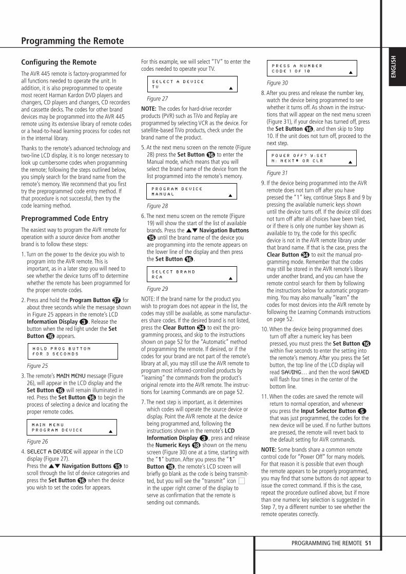
PROGRAMMING THE REMOTE 51
ENG
LISH
Programming the Remote
Configuring the RemoteThe AVR 445 remote is factory-programmed forall functions needed to operate the unit. Inaddition, it is also preprogrammed to operatemost recent Harman Kardon DVD players andchangers, CD players and changers, CD recordersand cassette decks. The codes for other branddevices may be programmed into the AVR 445remote using its extensive library of remote codesor a head-to-head learning process for codes notin the internal library.
Thanks to the remote’s advanced technology and two-line LCD display, it is no longer necessary to look up cumbersome codes when programmingthe remote; following the steps outlined below,you simply search for the brand name from theremote’s memory. We recommend that you firsttry the preprogrammed code entry method. Ifthat procedure is not successful, then try thecode learning method.
Preprogrammed Code EntryThe easiest way to program the AVR remote for operation with a source device from anotherbrand is to follow these steps:
1. Turn on the power to the device you wish toprogram into the AVR remote. This isimportant, as in a later step you will need tosee whether the device turns off to determinewhether the remote has been programmed forthe proper remote codes.
2. Press and hold the Program Button forabout three seconds while the message shown in Figure 25 appears in the remote’s LCDInformation Display 2. Release thebutton when the red light under the SetButton F appears.
Figure 25
3. The remote’s MAIN MENU message (Figure26), will appear in the LCD display and theSet Button F will remain illuminated inred. Press the Set Button F to begin theprocess of selecting a device and locating theproper remote codes.
Figure 26
4. SELECT A DEVICE will appear in the LCDdisplay (Figure 27).Press the ⁄¤ Navigation Buttons E toscroll through the list of device categories andpress the Set Button F when the deviceyou wish to set the codes for appears.
For this example, we will select “TV” to enter thecodes needed to operate your TV.
Figure 27
NOTE: The codes for hard-drive recorderproducts (PVR) such as TiVo and Replay areprogrammed by selecting VCR as the device. Forsatellite-based TiVo products, check under thebrand name of the product.
5. At the next menu screen on the remote (Figure28) press the Set Button F to enter theManual mode, which means that you willselect the brand name of the device from thelist programmed into the remote’s memory.
Figure 28
6. The next menu screen on the remote (Figure19) will show the start of the list of availablebrands. Press the ⁄¤ Navigation ButtonsE until the brand name of the device youare programming into the remote appears onthe lower line of the display and then pressthe Set Button F.
Figure 29
NOTE: If the brand name for the product youwish to program does not appear in the list, thecodes may still be available, as some manufactur-ers share codes. If the desired brand is not listed,press the Clear Button � to exit the pro-gramming process, and skip to the instructionsshown on page 52 for the “Automatic” methodof programming the remote. If desired, or if thecodes for your brand are not part of the remote’slibrary at all, you may still use the AVR remote toprogram most infrared-controlled products by“learning” the commands from the product’soriginal remote into the AVR remote. The instruc-tions for Learning Commands are on page 52.
7. The next step is important, as it determineswhich codes will operate the source device ordisplay. Point the AVR remote at the devicebeing programmed and, following theinstructions shown in the remote’s LCDInformation Display 2, press and releasethe Numeric Keys H shown on the menuscreen (Figure 30) one at a time, starting withthe “1” button. After you press the “1”Button H, the remote’s LCD screen willbriefly go blank as the code is being transmit-ted, but you will see the “transmit” icon in the upper right corner of the display toserve as confirmation that the remote issending out commands.
Figure 30
8. After you press and release the number key,watch the device being programmed to seewhether it turns off. As shown in the instruc-tions that will appear on the next menu screen(Figure 31), if your device has turned off, pressthe Set Button F, and then skip to Step10. If the unit does not turn off, proceed to thenext step.
Figure 31
9. If the device being programmed into the AVRremote does not turn off after you havepressed the “1” key, continue Steps 8 and 9 bypressing the available numeric keys shownuntil the device turns off. If the device still doesnot turn off after all choices have been tried,or if there is only one number key shown asavailable to try, the code for this specificdevice is not in the AVR remote library underthat brand name. If that is the case, press theClear Button � to exit the manual pro-gramming mode. Remember that the codesmay still be stored in the AVR remote’s libraryunder another brand, and you can have theremote control search for them by followingthe instructions below for automatic program-ming. You may also manually “learn” thecodes for most devices into the AVR remote byfollowing the Learning Commands instructionson page 52.
10. When the device being programmed doesturn off after a numeric key has beenpressed, you must press the Set Button Fwithin five seconds to enter the setting intothe remote’s memory. After you press the Setbutton, the top line of the LCD display willread SAVING… and then the word SAVED
will flash four times in the center of thebottom line.
11. When the codes are saved the remote willreturn to normal operation, and wheneveryou press the Input Selector Button 4that was just programmed, the codes for thenew device will be used. If no further buttonsare pressed, the remote will revert back tothe default setting for AVR commands.
NOTE: Some brands share a common remotecontrol code for “Power Off” for many models.For that reason it is possible that even thoughthe remote appears to be properly programmed,you may find that some buttons do not appear toissue the correct command. If this is the case,repeat the procedure outlined above, but if morethan one numeric key selection is suggested inStep 7, try a different number to see whether theremote operates correctly.
P O W E R O F F ? Y : S E T
N : N E X T # O R C L R
P R E S S A N U M B E R
C O D E 1 O F 1 0
S E L E C T B R A N D
R C A
P R O G R A M D E V I C E
M A N U A L
S E L E C T A D E V I C E
T V
M A I N M E N U
P R O G R A M D E V I C E
H O L D P R O G B U T T O N
F O R 3 S E C O N D S
30362_AVR445_ENG 20/11/06 14:56 Side 51
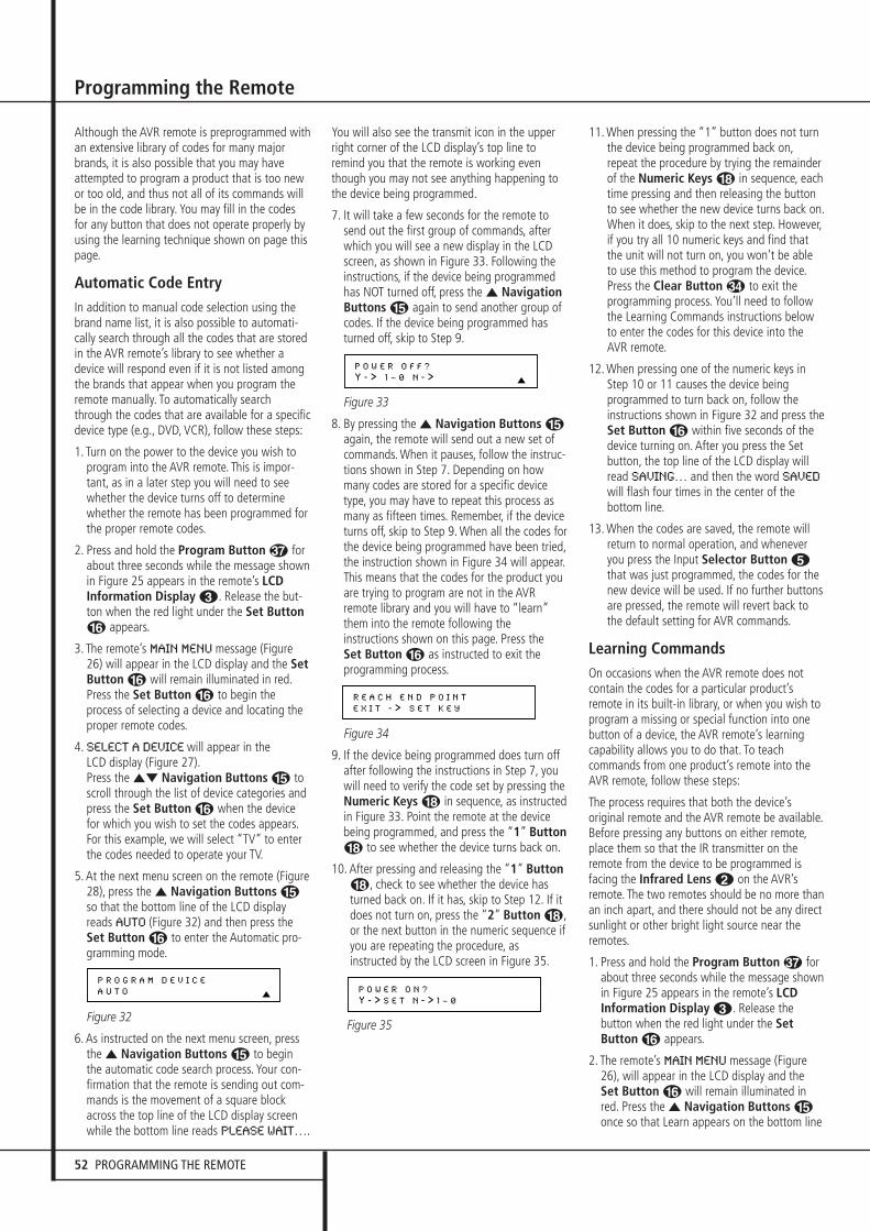
52 PROGRAMMING THE REMOTE
Programming the Remote
Although the AVR remote is preprogrammed withan extensive library of codes for many majorbrands, it is also possible that you may haveattempted to program a product that is too newor too old, and thus not all of its commands willbe in the code library. You may fill in the codesfor any button that does not operate properly byusing the learning technique shown on page thispage.
Automatic Code EntryIn addition to manual code selection using thebrand name list, it is also possible to automati-cally search through all the codes that are storedin the AVR remote’s library to see whether adevice will respond even if it is not listed amongthe brands that appear when you program theremote manually. To automatically searchthrough the codes that are available for a specificdevice type (e.g., DVD, VCR), follow these steps:
1. Turn on the power to the device you wish toprogram into the AVR remote. This is impor-tant, as in a later step you will need to seewhether the device turns off to determinewhether the remote has been programmed forthe proper remote codes.
2. Press and hold the Program Button forabout three seconds while the message shownin Figure 25 appears in the remote’s LCDInformation Display 2. Release the but-ton when the red light under the Set ButtonF appears.
3. The remote’s MAIN MENU message (Figure26) will appear in the LCD display and the SetButton F will remain illuminated in red.Press the Set Button F to begin theprocess of selecting a device and locating theproper remote codes.
4. SELECT A DEVICE will appear in the LCD display (Figure 27).Press the ⁄¤ Navigation Buttons E toscroll through the list of device categories andpress the Set Button F when the devicefor which you wish to set the codes appears.For this example, we will select “TV” to enterthe codes needed to operate your TV.
5. At the next menu screen on the remote (Figure28), press the ⁄ Navigation Buttons Eso that the bottom line of the LCD displayreads AUTO (Figure 32) and then press theSet Button F to enter the Automatic pro-gramming mode.
Figure 32
6. As instructed on the next menu screen, press the ⁄ Navigation Buttons E to beginthe automatic code search process. Your con-firmation that the remote is sending out com-mands is the movement of a square blockacross the top line of the LCD display screenwhile the bottom line reads PLEASE WAIT….
You will also see the transmit icon in the upperright corner of the LCD display’s top line toremind you that the remote is working eventhough you may not see anything happening tothe device being programmed.
7. It will take a few seconds for the remote tosend out the first group of commands, afterwhich you will see a new display in the LCDscreen, as shown in Figure 33. Following theinstructions, if the device being programmedhas NOT turned off, press the ⁄ NavigationButtons E again to send another group ofcodes. If the device being programmed hasturned off, skip to Step 9.
Figure 33
8. By pressing the ⁄ Navigation Buttons Eagain, the remote will send out a new set ofcommands. When it pauses, follow the instruc-tions shown in Step 7. Depending on howmany codes are stored for a specific devicetype, you may have to repeat this process asmany as fifteen times. Remember, if the deviceturns off, skip to Step 9. When all the codes forthe device being programmed have been tried,the instruction shown in Figure 34 will appear.This means that the codes for the product youare trying to program are not in the AVRremote library and you will have to “learn”them into the remote following theinstructions shown on this page. Press the Set Button F as instructed to exit theprogramming process.
Figure 34
9. If the device being programmed does turn offafter following the instructions in Step 7, you will need to verify the code set by pressing theNumeric Keys H in sequence, as instructedin Figure 33. Point the remote at the devicebeing programmed, and press the “1” ButtonH to see whether the device turns back on.
10. After pressing and releasing the “1” ButtonH, check to see whether the device hasturned back on. If it has, skip to Step 12. If itdoes not turn on, press the “2” Button H,or the next button in the numeric sequence ifyou are repeating the procedure, asinstructed by the LCD screen in Figure 35.
Figure 35
11. When pressing the “1” button does not turnthe device being programmed back on,repeat the procedure by trying the remainderof the Numeric Keys H in sequence, eachtime pressing and then releasing the buttonto see whether the new device turns back on.When it does, skip to the next step. However,if you try all 10 numeric keys and find thatthe unit will not turn on, you won’t be ableto use this method to program the device.Press the Clear Button � to exit theprogramming process. You’ll need to followthe Learning Commands instructions belowto enter the codes for this device into theAVR remote.
12. When pressing one of the numeric keys inStep 10 or 11 causes the device beingprogrammed to turn back on, follow theinstructions shown in Figure 32 and press theSet Button F within five seconds of thedevice turning on. After you press the Setbutton, the top line of the LCD display willread SAVING… and then the word SAVED
will flash four times in the center of thebottom line.
13. When the codes are saved, the remote willreturn to normal operation, and wheneveryou press the Input Selector Button 4that was just programmed, the codes for thenew device will be used. If no further buttonsare pressed, the remote will revert back tothe default setting for AVR commands.
Learning CommandsOn occasions when the AVR remote does notcontain the codes for a particular product’sremote in its built-in library, or when you wish toprogram a missing or special function into onebutton of a device, the AVR remote’s learningcapability allows you to do that. To teachcommands from one product’s remote into theAVR remote, follow these steps:
The process requires that both the device’soriginal remote and the AVR remote be available.Before pressing any buttons on either remote,place them so that the IR transmitter on theremote from the device to be programmed isfacing the Infrared Lens 1 on the AVR’sremote. The two remotes should be no more thanan inch apart, and there should not be any directsunlight or other bright light source near theremotes.
1. Press and hold the Program Button forabout three seconds while the message shown in Figure 25 appears in the remote’s LCDInformation Display 2. Release thebutton when the red light under the SetButton F appears.
2. The remote’s MAIN MENU message (Figure26), will appear in the LCD display and theSet Button F will remain illuminated inred. Press the ⁄ Navigation Buttons Eonce so that Learn appears on the bottom line
P O W E R O N ?
Y - > S E T N - > 1 ~ 0
R E A C H E N D P O I N T
E X I T - > S E T K E Y
P O W E R O F F ?
Y - > 1 ~ 0 N - >
P R O G R A M D E V I C E
A U T O
30362_AVR445_ENG 20/11/06 14:56 Side 52
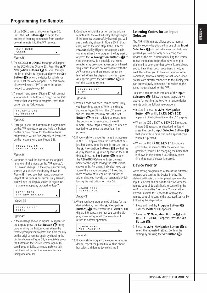
PROGRAMMING THE REMOTE 53
ENG
LISH
Programming the Remote
of the LCD screen, as shown in Figure 36.Press the Set Button F to begin theprocess of learning commands from anotherdevice’s remote into the AVR remote.
Figure 36
3. The SELECT A DEVICE message will appearin the LCD display (Figure 27). Press the ⁄¤
Navigation Buttons E to scroll throughthe list of device categories and press the SetButton F when the device for which youwish to set the codes appears. For this exam-ple, we will select “TV” to enter the codesneeded to operate your TV.
4. The next menu screen (Figure 37) will promptyou to select the button, or “key,” on the AVRremote that you wish to program. Press thatbutton on the AVR remote.
Figure 37
5. Once you press the button to be programmedon the AVR remote, press and hold the buttonon the remote control for the device to beprogrammed within five seconds, as instructedon the next menu screen (Figure 38).
Figure 38
6. Continue to hold the button on the originalremote until the menu on the AVR remote’sLCD screen changes. If the code is successfullylearned you will see the display shown inFigure 39. If you see that menu, proceed toStep 9. If the code is not successfully learned,you will see the display shown in Figure 40.If that menu appears, proceed to Step 7.
Figure 39
Figure 40
7. If the message shown in Figure 36 appears in the display, press the Set Button F to tryprogramming the button again. When theremote prompts you to press and hold the keyon the original remote again by showing thedisplay shown in Figure 38, immediately pressthe button on the source remote again. Toavoid another failed attempt, make certainthat the windows on the two remotes arefacing one another.
8. Continue to hold the button on the originalremote until the AVR’s display changes again.If the code was successfully learned, you willsee the display shown in Figure 35. In thatcase, skip to the next step. If the LEARN
FAILED display (Figure 40) appears againyou may either try to program the key again,or press the ⁄ Navigation Buttons E tostop the process. It is possible that someremotes may use code sequences or infraredfrequencies that are not compatible with theAVR remote, and those codes cannot belearned. When the display shown in Figure41 appears, press the Set Button F toexit the Learning system.
Figure 41
9. When a code has been learned successfully,you have three options. When the displayshown in Figure 39 is on the LCD screen onthe AVR remote, you may press the SetButton F to learn additional codes fromthe buttons on a remote into the AVRremote. Follow Steps 4 through 8 as often asneeded to complete the code-learningprocess.
10. If you wish to change the name that appearsin the LCD display when the button that hasjust had a new code learned is pressed, pressthe ⁄ Navigation Buttons E so that thedisplay shown in Figure 42 appears in the LCDdisplay. Press the Set Button F to openthe RENAME KEY menu. Enter the newname for the key following the instructionsshown in the Renaming Individual Keys sec-tion of this manual on page 57. If you find itmore convenient to rename the buttons at a later time, you may do that separately by fol-lowing the instructions on page 58.
Figure 42
11. When you have programmed all keys for thedesired device, press the ⁄ NavigationButtons E twice when the LEARN MENU
(Figure 39) appears so that you see the dis-play show in Figure 43. The remote willreturn to normal operation.
Figure 43
12. If you wish to program the codes for anotherdevice, repeat the procedure outline above,but select a different device in Step 3.
Learning Codes for an InputSelector
The AVR 445’s remote allows you to learn aspecific code to be attached to one of the InputSelectors 4 so that whenever that button ispressed, you will not only be selecting thatdevice as the AVR’s input and telling the remoteto use the remote codes that have been pro-grammed to belong to that device, it also allowsyou to have that special code transmitted, aswell. This allows you to have an input (or othercommand) sent to a display so that when videosources are directly connected to the display, youcan automatically command it to switch to thesame input selected for the AVR.
To learn a remote code into one of the InputSelectors 4, follow the same steps shownabove for learning the keys for an entire deviceremote with the following exceptions:
• In Step 3, press the ⁄/¤ NavigationButton E until LEARNDEVICEappears in the bottom line of the LCD display.
• When the SELECTA DEVICEmessage(Figure 36) appears, as described in Step 4,press the specific Input Selector Button 4that you wish to have transmit a special codewhen it is pressed.
• When the RENAMEDEVICE option isoffered by the remote after the code is pro-grammed, you will be changing the name thatis shown in the remote’s LCD display everytime that Input Selector is pressed.
Device PriorityAfter having programmed or learnt the differentsources, you can set the Device Priority. Thedefault setting is that after pressing one of theInput Selectors and any of its function keys, theremote control defaults back to controlling theAVR functions after 6 seconds. You can eitherextend this time to 12 seconds, or leave theremote control to control the last used source, byfollowing the steps below.
1. Press and hold the Program Button until the MAIN MENU appears.
2. Press the ¤ Navigation Button E untilDEVICE PRIORITY appears. Press the SetButton F.
3. Press the ⁄/¤ Navigation Button E toselect the requested setting. Confirm thesetting by pressing the Set Button F.
L E A R N M E N U
E N D L E A R N I N G
L E A R N M E N U
R E N A M E K E Y
L E A R N F A I L E D
E X I T
L E A R N F A I L E D
R E T R Y
L E A R N M E N U
L R N A N O T H E R K E Y
P R E S S K E Y O N
O R I G I N A L R E M O T E
S E L E C T A K E Y
T O P R O G R A M
M A I N M E N U
L E A R N
30362_AVR445_ENG 20/11/06 14:56 Side 53
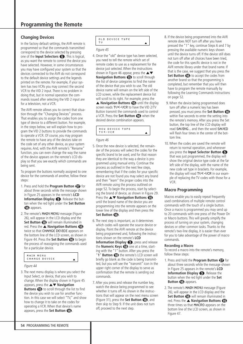
54 PROGRAMMING THE REMOTE
Programming the Remote
Changing DevicesIn the factory default settings, the AVR remote is programmed so that the commands transmitted correspond to the device selected by pressingone of the Input Selectors 4. This is logical,as you want the remote to control the device youhave selected. However, in some circumstancesyou may have configured your system so that thedevices connected to the AVR do not correspondto the default device settings and the legendsprinted on the remote. For example, if your sys-tem has two VCRs you may connect the secondVCR to the VID 2 input. There is no problem indoing that, but in normal operation the com-mands issued after selecting the VID 2 input arefor a television, not a VCR.
The AVR remote allows you to correct that situa-tion through the “Changing Devices” process.That enables you to assign the codes from onetype of device to a different button. For example,in the steps below, we will explain how to pro-gram the VID 2 buttons to provide the commandsto operate a VCR. Of course, you may programthe remote to have any of the devices take onthe code set of any other device, as your systemrequires. And, with the AVR remote’s “Rename”function, you can even change the way the nameof the device appears on the remote’s LCD dis-play so that you see exactly which commands arebeing sent.
To program the buttons normally assigned to onedevice for the commands of another, follow thesesteps:
1. Press and hold the Program Button forabout three seconds while the message shownin Figure 25 appears in the remote’s LCDInformation Display 2. Release the but-ton when the red light under the Set ButtonF appears.
2. The remote’s MAIN MENU message (Figure26), will appear in the LCD display and theSet Button F will remain illuminated inred. Press the ⁄ Navigation Buttons Etwice so that CHANGE DEVICE appears onthe bottom line of the LCD screen, as shown inFigure 44. Press the Set Button F to beginthe process of reassigning the commands usedfor a particular device.
Figure 44
3. The next menu display is where you select theInput Select, or device, that you wish tochange. When the display shown in Figure 45appears, press the ⁄¤ NavigationButtons E to scroll through the list to findthe device you wish to use for another func-tion. In this case we will select “TV,” and showhow to change it to take on the codes foroperating a VCR. When that device’s nameappears, press the Set Button F.
Figure 45
4. Once the “old” device type has been selected,you need to tell the remote which set ofremote codes to use as a replacement for thedevice just selected. When the instructionsshown in Figure 46 appear, press the ⁄¤
Navigation Buttons E to scroll throughthe list of device categories to find the nameof the device that you wish to use. The olddevice name will remain on the left side of theLCD screen, while the replacement device listwill scroll to its right. For example, press the⁄ Navigation Buttons E until the displayscreen reads TV<-VCR to have the VID 2/TVButton transmit the commands used to controla VCR. Press the Set Button F when thedesired device combination appears.
Figure 46
5. Once the new device is selected, the remain-der of the process will select the codes for thespecific brand to be used, and for that reasonthey are identical to the way a device is pro-grammed using manual entry. Continue theprocess as outlined in the next few steps,remembering that if the codes for your specificdevice are not found you may select any brandand then “learn” the proper codes into theAVR remote using the process outlined onpage 52. To begin the process, start by select-ing the brand of device, as shown in Figure 29.Press the ⁄¤ Navigation Buttons Euntil the brand name of the device you areprogramming into the remote appears on thelower line of the display and then press theSet Button F.
6. The next step is important, as it determineswhich codes will operate the source device ordisplay. Point the AVR remote at the devicebeing programmed and, following the instruc-tions shown on the remote’s LCDInformation Display 2, press and releasethe Numeric Keys H one at a time, start-ing with the “1” button. After you press the“1” Button H the remote’s LCD screen willbriefly go blank as the code is being transmit-ted, but you will see the “transmit” icon in theupper right corner of the display to serve asconfirmation that the remote is sending outcommands.
7. After you press and release the number key,watch the device being programmed to seewhether it turns off. As shown in the instruc-tions that will appear on the next menu screen(Figure 31), press the Set Button F, andthen skip to Step 9. If the unit does not turnoff, proceed to the next step.
8. If the device being programmed into the AVRremote does NOT turn off after you havepressed the “1” key, continue Steps 6 and 7 bypressing the available numeric keys shownuntil the device turns off. If the device still doesnot turn off after all choices have been tried,the code for this specific device is not in theAVR remote library under that brand name. Ifthat is the case, we suggest that you press theSet Button F to accept the codes fromanother brand so that the programming iscompleted, but remember that you will thenhave to program the remote manually byfollowing the Learning Commands instructionson page 52.
9. When the device being programmed doesturn off after a numeric key has beenpressed, you must press the Set Button Fwithin five seconds to enter the setting intothe remote’s memory. After you press the Setbutton, the top line of the LCD display willread SAVING... and then the word SAVED
will flash four times in the center of the bot-tom line.
10. When the codes are saved the remote willreturn to normal operation, and wheneveryou press the Input Selector Button 4that was just programmed, the display willshow the original device type code at the farleft side of the display, with the name of thenew code set type in brackets. For example,the display will read TV<-VCR in our exam-ple of replacing the TV codes with those for aVCR.
Macro ProgrammingMacros enable you to easily repeat frequentlyused combinations of multiple remote controlcommands with the touch of a single button.Once a macro is programmed you may send upto 20 commands with one press of the Power Onor Macro buttons. This will greatly simplify theprocess of turning on your system, changingdevices or other common tasks. Thanks to theremote’s two-line display, it is easier than everfor you to take advantage of the power of macrocommands.
Recording a MacroTo record a macro into the remote’s memory,follow these steps:
1. Press and hold the Program Button forabout three seconds while the message shown in Figure 25 appears in the remote’s LCDInformation Display 2. Release thebutton when the red light under the SetButton F appears.
2. The remote’s MAIN MENU message (Figure26), will appear in the LCD display and theSet Button F will remain illuminated inred. Press the ⁄ Navigation Buttons Ethree times so that MACRO appears on thebottom line of the LCD screen, as shown inFigure 47.
N E W D E V I C E T Y P E
T V < - V C R
O L D D E V I C E T Y P E
T V
M A I N M E N U
C H A N G E D E V I C E
30362_AVR445_ENG 20/11/06 14:56 Side 54
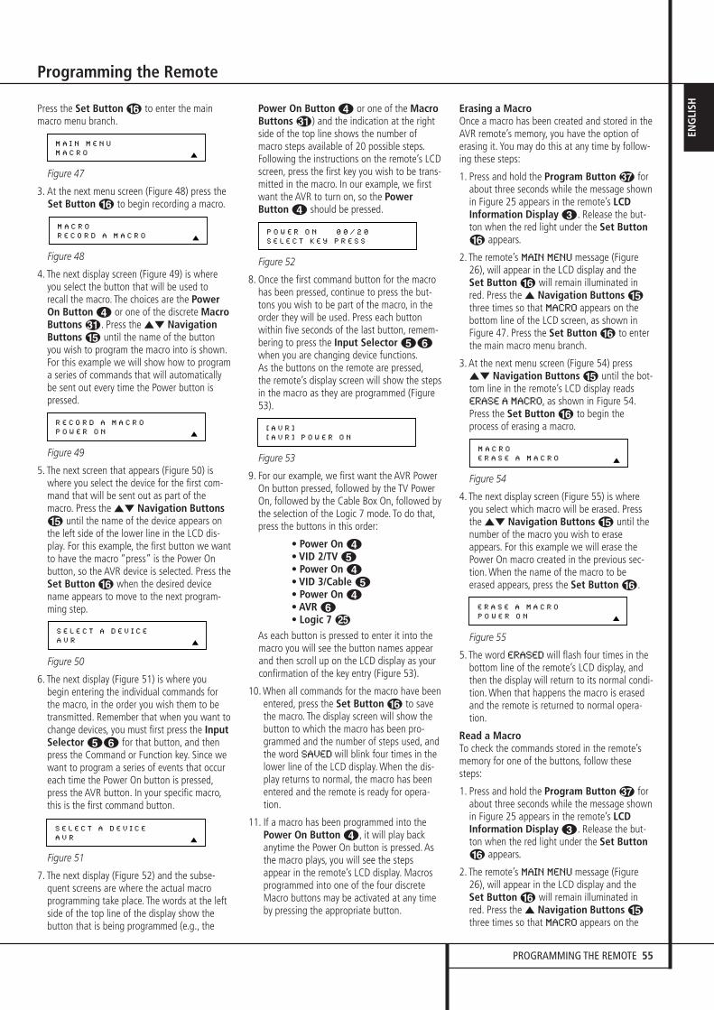
PROGRAMMING THE REMOTE 55
ENG
LISH
Programming the Remote
Press the Set Button F to enter the mainmacro menu branch.
Figure 47
3. At the next menu screen (Figure 48) press the Set Button F to begin recording a macro.
Figure 48
4. The next display screen (Figure 49) is whereyou select the button that will be used torecall the macro. The choices are the PowerOn Button 3 or one of the discrete MacroButtons �. Press the ⁄¤ NavigationButtons E until the name of the buttonyou wish to program the macro into is shown.For this example we will show how to programa series of commands that will automaticallybe sent out every time the Power button ispressed.
Figure 49
5. The next screen that appears (Figure 50) iswhere you select the device for the first com-mand that will be sent out as part of themacro. Press the ⁄¤ Navigation ButtonsE until the name of the device appears onthe left side of the lower line in the LCD dis-play. For this example, the first button we wantto have the macro “press” is the Power Onbutton, so the AVR device is selected. Press theSet Button F when the desired devicename appears to move to the next program-ming step.
Figure 50
6. The next display (Figure 51) is where youbegin entering the individual commands forthe macro, in the order you wish them to betransmitted. Remember that when you want tochange devices, you must first press the InputSelector 45 for that button, and thenpress the Command or Function key. Since wewant to program a series of events that occureach time the Power On button is pressed,press the AVR button. In your specific macro,this is the first command button.
Figure 51
7. The next display (Figure 52) and the subse-quent screens are where the actual macroprogramming take place. The words at the leftside of the top line of the display show thebutton that is being programmed (e.g., the
Power On Button 3 or one of the MacroButtons �) and the indication at the rightside of the top line shows the number ofmacro steps available of 20 possible steps.Following the instructions on the remote’s LCDscreen, press the first key you wish to be trans-mitted in the macro. In our example, we firstwant the AVR to turn on, so the PowerButton 3 should be pressed.
Figure 52
8. Once the first command button for the macrohas been pressed, continue to press the but-tons you wish to be part of the macro, in theorder they will be used. Press each buttonwithin five seconds of the last button, remem-bering to press the Input Selector 45when you are changing device functions.As the buttons on the remote are pressed,the remote’s display screen will show the stepsin the macro as they are programmed (Figure53).
Figure 53
9. For our example, we first want the AVR PowerOn button pressed, followed by the TV PowerOn, followed by the Cable Box On, followed bythe selection of the Logic 7 mode. To do that,press the buttons in this order:
• Power On 3• VID 2/TV 4• Power On 3• VID 3/Cable 4• Power On 3• AVR 5• Logic 7 O
As each button is pressed to enter it into themacro you will see the button names appearand then scroll up on the LCD display as yourconfirmation of the key entry (Figure 53).
10. When all commands for the macro have beenentered, press the Set Button F to savethe macro. The display screen will show thebutton to which the macro has been pro-grammed and the number of steps used, andthe word SAVED will blink four times in thelower line of the LCD display. When the dis-play returns to normal, the macro has beenentered and the remote is ready for opera-tion.
11. If a macro has been programmed into thePower On Button 3, it will play backanytime the Power On button is pressed. Asthe macro plays, you will see the stepsappear in the remote’s LCD display. Macrosprogrammed into one of the four discreteMacro buttons may be activated at any timeby pressing the appropriate button.
Erasing a MacroOnce a macro has been created and stored in theAVR remote’s memory, you have the option oferasing it. You may do this at any time by follow-ing these steps:
1. Press and hold the Program Button forabout three seconds while the message shownin Figure 25 appears in the remote’s LCDInformation Display 2. Release the but-ton when the red light under the Set ButtonF appears.
2. The remote’s MAIN MENU message (Figure26), will appear in the LCD display and theSet Button F will remain illuminated inred. Press the ⁄ Navigation Buttons Ethree times so that MACRO appears on thebottom line of the LCD screen, as shown inFigure 47. Press the Set Button F to enterthe main macro menu branch.
3. At the next menu screen (Figure 54) press⁄¤ Navigation Buttons E until the bot-tom line in the remote’s LCD display readsERASE A MACRO, as shown in Figure 54.Press the Set Button F to begin theprocess of erasing a macro.
Figure 54
4. The next display screen (Figure 55) is whereyou select which macro will be erased. Pressthe ⁄¤ Navigation Buttons E until thenumber of the macro you wish to eraseappears. For this example we will erase thePower On macro created in the previous sec-tion. When the name of the macro to beerased appears, press the Set Button F.
Figure 55
5. The word ERASED will flash four times in thebottom line of the remote’s LCD display, andthen the display will return to its normal condi-tion. When that happens the macro is erasedand the remote is returned to normal opera-tion.
Read a MacroTo check the commands stored in the remote’smemory for one of the buttons, follow thesesteps:
1. Press and hold the Program Button forabout three seconds while the message shownin Figure 25 appears in the remote’s LCDInformation Display 2. Release the but-ton when the red light under the Set ButtonF appears.
2. The remote’s MAIN MENU message (Figure26), will appear in the LCD display and theSet Button F will remain illuminated inred. Press the ⁄ Navigation Buttons Ethree times so that MACRO appears on the
E R A S E A M A C R O
P O W E R O N
M A C R O
E R A S E A M A C R O
[ A V R ]
[ A V R ] P O W E R O N
P O W E R O N 0 0 / 2 0
S E L E C T K E Y P R E S S
S E L E C T A D E V I C E
A V R
S E L E C T A D E V I C E
A V R
R E C O R D A M A C R O
P O W E R O N
M A C R O
R E C O R D A M A C R O
M A I N M E N U
M A C R O
30362_AVR445_ENG 20/11/06 14:56 Side 55
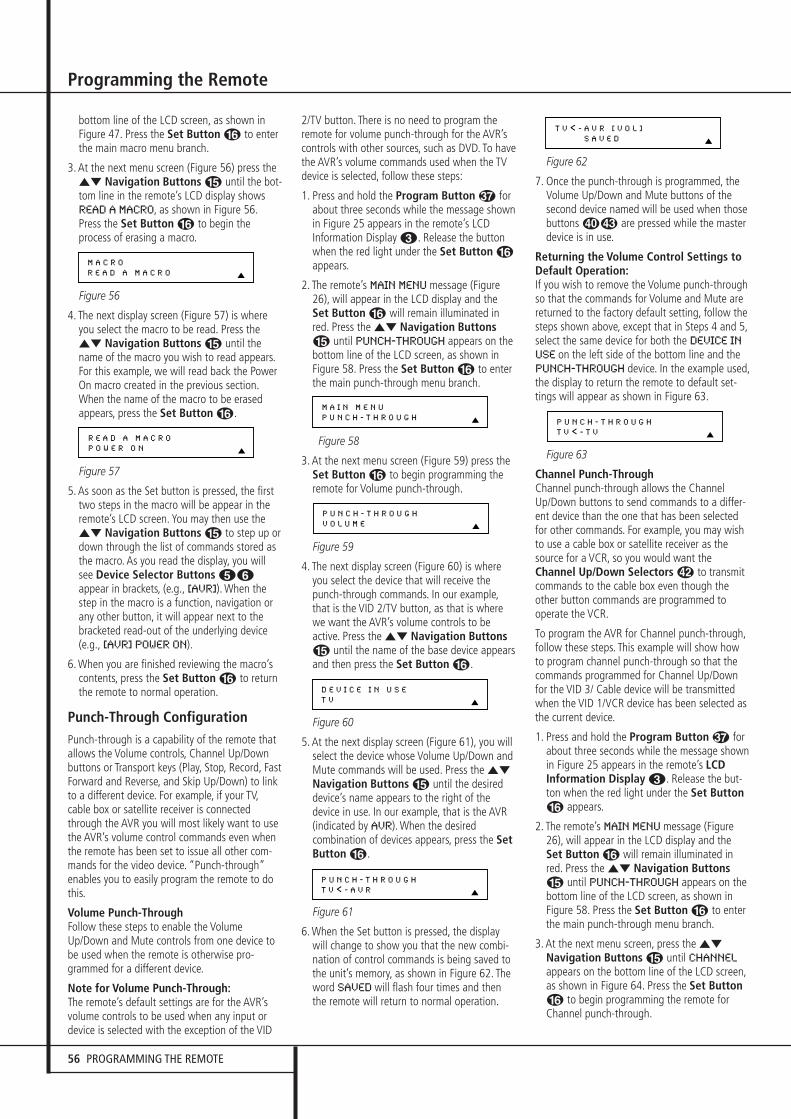
56 PROGRAMMING THE REMOTE
Programming the Remote
bottom line of the LCD screen, as shown inFigure 47. Press the Set Button F to enterthe main macro menu branch.
3. At the next menu screen (Figure 56) press the⁄¤ Navigation Buttons E until the bot-tom line in the remote’s LCD display showsREAD A MACRO, as shown in Figure 56.Press the Set Button F to begin theprocess of erasing a macro.
Figure 56
4. The next display screen (Figure 57) is whereyou select the macro to be read. Press the⁄¤ Navigation Buttons E until thename of the macro you wish to read appears.For this example, we will read back the PowerOn macro created in the previous section.When the name of the macro to be erasedappears, press the Set Button F.
Figure 57
5. As soon as the Set button is pressed, the firsttwo steps in the macro will be appear in theremote’s LCD screen. You may then use the⁄¤ Navigation Buttons E to step up ordown through the list of commands stored asthe macro. As you read the display, you willsee Device Selector Buttons 45appear in brackets, (e.g., [AVR]). When thestep in the macro is a function, navigation orany other button, it will appear next to thebracketed read-out of the underlying device(e.g., [AVR] POWER ON).
6. When you are finished reviewing the macro’s contents, press the Set Button F to return the remote to normal operation.
Punch-Through ConfigurationPunch-through is a capability of the remote that allows the Volume controls, Channel Up/Downbuttons or Transport keys (Play, Stop, Record, FastForward and Reverse, and Skip Up/Down) to linkto a different device. For example, if your TV,cable box or satellite receiver is connectedthrough the AVR you will most likely want to usethe AVR’s volume control commands even whenthe remote has been set to issue all other com-mands for the video device. “Punch-through”enables you to easily program the remote to dothis.
Volume Punch-ThroughFollow these steps to enable the VolumeUp/Down and Mute controls from one device tobe used when the remote is otherwise pro-grammed for a different device.
Note for Volume Punch-Through:The remote’s default settings are for the AVR’svolume controls to be used when any input ordevice is selected with the exception of the VID
2/TV button. There is no need to program theremote for volume punch-through for the AVR’scontrols with other sources, such as DVD. To havethe AVR’s volume commands used when the TVdevice is selected, follow these steps:
1. Press and hold the Program Button forabout three seconds while the message shown in Figure 25 appears in the remote’s LCDInformation Display 2. Release the buttonwhen the red light under the Set Button Fappears.
2. The remote’s MAIN MENU message (Figure26), will appear in the LCD display and theSet Button F will remain illuminated inred. Press the ⁄¤ Navigation ButtonsE until PUNCH-THROUGH appears on thebottom line of the LCD screen, as shown inFigure 58. Press the Set Button F to enterthe main punch-through menu branch.
Figure 58
3. At the next menu screen (Figure 59) press the Set Button F to begin programming theremote for Volume punch-through.
Figure 59
4. The next display screen (Figure 60) is whereyou select the device that will receive thepunch-through commands. In our example,that is the VID 2/TV button, as that is wherewe want the AVR’s volume controls to beactive. Press the ⁄¤ Navigation ButtonsE until the name of the base device appearsand then press the Set Button F.
Figure 60
5. At the next display screen (Figure 61), you willselect the device whose Volume Up/Down andMute commands will be used. Press the ⁄¤
Navigation Buttons E until the desireddevice’s name appears to the right of thedevice in use. In our example, that is the AVR(indicated by AVR). When the desired combination of devices appears, press the SetButton F.
Figure 61
6. When the Set button is pressed, the displaywill change to show you that the new combi-nation of control commands is being saved tothe unit’s memory, as shown in Figure 62. Theword SAVED will flash four times and thenthe remote will return to normal operation.
Figure 62
7. Once the punch-through is programmed, theVolume Up/Down and Mute buttons of thesecond device named will be used when thosebuttons � are pressed while the masterdevice is in use.
Returning the Volume Control Settings to Default Operation:If you wish to remove the Volume punch-throughso that the commands for Volume and Mute arereturned to the factory default setting, follow thesteps shown above, except that in Steps 4 and 5,select the same device for both the DEVICE IN
USE on the left side of the bottom line and thePUNCH-THROUGH device. In the example used,the display to return the remote to default set-tings will appear as shown in Figure 63.
Figure 63
Channel Punch-ThroughChannel punch-through allows the ChannelUp/Down buttons to send commands to a differ-ent device than the one that has been selectedfor other commands. For example, you may wishto use a cable box or satellite receiver as thesource for a VCR, so you would want theChannel Up/Down Selectors � to transmitcommands to the cable box even though theother button commands are programmed tooperate the VCR.
To program the AVR for Channel punch-through,follow these steps. This example will show howto program channel punch-through so that thecommands programmed for Channel Up/Downfor the VID 3/ Cable device will be transmittedwhen the VID 1/VCR device has been selected asthe current device.
1. Press and hold the Program Button forabout three seconds while the message shown in Figure 25 appears in the remote’s LCDInformation Display 2. Release the but-ton when the red light under the Set ButtonF appears.
2. The remote’s MAIN MENU message (Figure26), will appear in the LCD display and theSet Button F will remain illuminated inred. Press the ⁄¤ Navigation ButtonsE until PUNCH-THROUGH appears on thebottom line of the LCD screen, as shown inFigure 58. Press the Set Button F to enterthe main punch-through menu branch.
3. At the next menu screen, press the ⁄¤
Navigation Buttons E until CHANNEL
appears on the bottom line of the LCD screen,as shown in Figure 64. Press the Set ButtonF to begin programming the remote forChannel punch-through.
P U N C H - T H R O U G H
T V < - T V
T V < - A V R [ V O L ]
S A V E D
P U N C H - T H R O U G H
T V < - A V R
D E V I C E I N U S E
T V
P U N C H - T H R O U G H
V O L U M E
M A I N M E N U
P U N C H - T H R O U G H
R E A D A M A C R O
P O W E R O N
M A C R O
R E A D A M A C R O
30362_AVR445_ENG 20/11/06 14:56 Side 56

PROGRAMMING THE REMOTE 57
ENG
LISH
Programming the Remote
Figure 64
4. The next display screen (Figure 65) is whereyou select the device that will receive thepunch-through commands. In our example,that is the VID 1/VCR button, as that is wherewe want the cable box’s channel controls tobe active. Press the ⁄¤ NavigationButtons E until the name of the basedevice appears and then press the SetButton F.
Figure 65
5. At the next display screen (Figure 66), you willselect the device whose Channel Up/Downcommands will be used. Press the ⁄¤
Navigation Buttons E until the desireddevice name appears to the right of the devicein use. In our example, that is the cable box.When the desired combination of devicesappears, press the Set Button F.
Figure 66
6. When the Set button is pressed, the displaywill change to show you that the new combi-nation of control commands is being saved tothe unit’s memory, as shown in Figure 67. Theword SAVED will flash four times and thenthe remote will return to normal operation.
Figure 67
7. Once the punch-through is programmed, thechannel up/down buttons of the second devicenamed will be used when those buttons �are pressed while the master device is in use.
Returning the Channel Control Settings toDefault Operation:If you wish to remove the Channel Punch-Through so that the commands for ChannelUp/Down are returned to the factory default set-ting, follow the steps shown above, except thatin Steps 4 and 5, select the same device for boththe DEVICE IN USE on the left side of the bot-tom line and the PUNCH-THROUGH device. Inthe example used, the display to return theremote to default settings will appear as shownin Figure 68.
Figure 68
Transport Punch-ThroughTransport punch-through allows the Play P,Stop P, Fast Forward/Reverse P, PauseP, Record P and Skip Up/Down � but-tons to send commands to a different devicethan the one that has been selected for othercommands. For example, you may wish to oper-ate the transport of a second VCR you have con-nected to the VID 2/TV input, as shown in thefollowing example.
1. Press and hold the Program Button forabout three seconds while the message shown in Figure 25 appears in the remote’s LCDInformation Display 2. Release the but-ton when the red light under the Set ButtonF appears.
2. The remote’s MAIN MENU message (Figure26), will appear in the LCD display and theSet Button F will remain illuminated inred. Press the ⁄¤ Navigation ButtonsE until PUNCH-THROUGH appears on thebottom line of the LCD screen, as shown inFigure 58. Press the Set Button F to enterthe main punch-through menu branch.
3. At the next menu screen, press the ⁄¤
Navigation Buttons E until TRANS-
PORT appears on the bottom line of the LCDscreen, as shown in Figure 69. Press the SetButton F to begin programming theremote for transport punch-through.
Figure 69
4. The next display screen (Figure 70) is whereyou select the device that will receive thepunch-through commands. In our example,that is the TV button, as that is where we wantthe VCR’s transport controls to be active. Pressthe ⁄¤ Navigation Buttons E until thename of the base device appears and thenpress the Set Button F.
Figure 70
5. At the next display screen (Figure 71), you willselect the device whose transport commandswill be used. Press the ⁄¤ NavigationButtons E until the desired device nameappears to the right of the device in use. In ourexample, that is the VCR. When the desiredcombination of devices appears, press the SetButton F.
Figure 71
6. When the Set button is pressed, the displaywill change to show you that the new combi-nation of control commands is being saved tothe unit’s memory, as shown in Figure 72.
The word SAVED will flash four times and thenthe remote will return to normal operation.
Figure 72
7. Once the punch-through is programmed, thetransport buttons of the second device namedwill be used when those buttons are pressedwhile the master device is in use.
Returning the Transport Control Settingsto Default Operation:If you wish to remove the Transport Punch-Through so that the transport commands arereturned to the factory default setting, follow thesteps shown above, except that in Steps 4 and 5,select the same device for both the DEVICE IN
USE on the left side of the bottom line and thePUNCH-THROUGH device. In the example used,the display to return the remote to default set-tings will appear as shown in Figure 73.
Figure 73
RenamingWhile the names given to the buttons and inputson the AVR represent recognizable categories ofaudio/ video products, system operation may beeasier if the displays shown in the remote’s LCDscreen are customized to reflect the specific char-acteristics of a playback source’s brand name orthe new function given to a specific button whenone remote’s controls are programmed into theAVR remote. The AVR remote allows you tochange the name of either a master device orany button on the remote using the followingsteps.
Renaming a DeviceTo rename a specific device/input source button,follow these steps. For this example, we willshow you how to rename the Device/InputSelector normally shown as “TV” to “HDTVTUNER.”
1. Press and hold the Program Button forabout three seconds while the message shown in Figure 25 appears in the remote’s LCDInformation Display 2. Release the but-ton when the red light under the Set ButtonF appears.
2. The remote’s MAIN MENU message (Figure26), will appear in the LCD display and theSet Button F will remain illuminated inred. Press the ⁄¤ Navigation ButtonsE until RENAME appears on the bottomline of the LCD screen, as shown in Figure 74.
Figure 74
M A I N M E N U
R E N A M E
P U N C H - T H R O U G H
T V < - T V
T V < - V C R [ T R S ]
S A V E D
P U N C H - T H R O U G H
T V < - V C R
D E V I C E I N U S E
T V
P U N C H - T H R O U G H
T R A N S P O R T
P U N C H - T H R O U G H
V C R < - V C R
V C R < - C B L [ C H A N ]
S A V E D
P U N C H - T H R O U G H
V C R < - C B L
D E V I C E I N U S E
V C R
P U N C H - T H R O U G H
C H A N N E L
30362_AVR445_ENG 20/11/06 14:56 Side 57
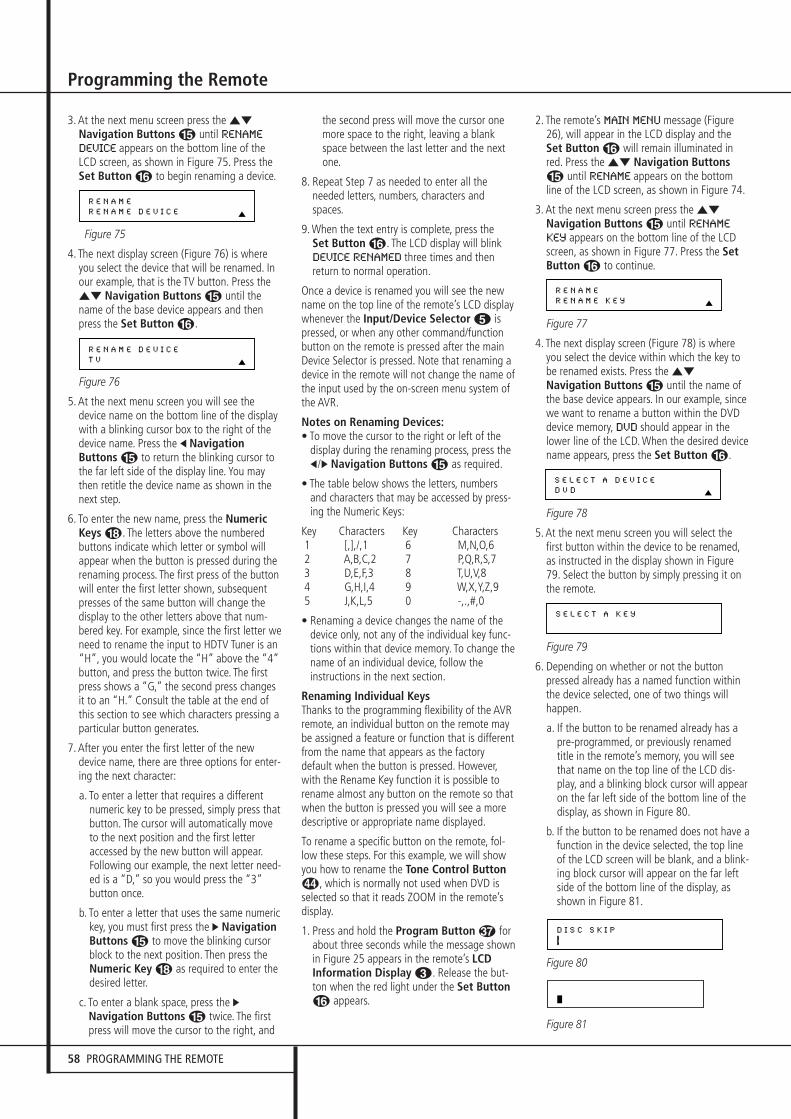
58 PROGRAMMING THE REMOTE
Programming the Remote
3. At the next menu screen press the ⁄¤
Navigation Buttons E until RENAME
DEVICE appears on the bottom line of theLCD screen, as shown in Figure 75. Press theSet Button F to begin renaming a device.
Figure 75
4. The next display screen (Figure 76) is whereyou select the device that will be renamed. Inour example, that is the TV button. Press the⁄¤ Navigation Buttons E until thename of the base device appears and thenpress the Set Button F.
Figure 76
5. At the next menu screen you will see thedevice name on the bottom line of the displaywith a blinking cursor box to the right of thedevice name. Press the ‹ NavigationButtons E to return the blinking cursor tothe far left side of the display line. You maythen retitle the device name as shown in thenext step.
6. To enter the new name, press the NumericKeys H. The letters above the numberedbuttons indicate which letter or symbol willappear when the button is pressed during therenaming process. The first press of the buttonwill enter the first letter shown, subsequentpresses of the same button will change thedisplay to the other letters above that num-bered key. For example, since the first letter weneed to rename the input to HDTV Tuner is an“H”, you would locate the “H” above the “4”button, and press the button twice. The firstpress shows a “G,” the second press changesit to an “H.” Consult the table at the end ofthis section to see which characters pressing aparticular button generates.
7. After you enter the first letter of the newdevice name, there are three options for enter-ing the next character:
a. To enter a letter that requires a different numeric key to be pressed, simply press thatbutton. The cursor will automatically moveto the next position and the first letteraccessed by the new button will appear.Following our example, the next letter need-ed is a “D,” so you would press the “3”button once.
b. To enter a letter that uses the same numerickey, you must first press the › NavigationButtons E to move the blinking cursorblock to the next position. Then press theNumeric Key H as required to enter thedesired letter.
c. To enter a blank space, press the ›Navigation Buttons E twice. The firstpress will move the cursor to the right, and
the second press will move the cursor onemore space to the right, leaving a blankspace between the last letter and the nextone.
8. Repeat Step 7 as needed to enter all theneeded letters, numbers, characters andspaces.
9. When the text entry is complete, press the Set Button F. The LCD display will blinkDEVICE RENAMED three times and thenreturn to normal operation.
Once a device is renamed you will see the newname on the top line of the remote’s LCD displaywhenever the Input/Device Selector 4 ispressed, or when any other command/functionbutton on the remote is pressed after the mainDevice Selector is pressed. Note that renaming adevice in the remote will not change the name ofthe input used by the on-screen menu system ofthe AVR.
Notes on Renaming Devices:• To move the cursor to the right or left of the
display during the renaming process, press the‹/› Navigation Buttons E as required.
• The table below shows the letters, numbersand characters that may be accessed by press-ing the Numeric Keys:
Key Characters Key Characters1 [,],/,1 6 M,N,O,62 A,B,C,2 7 P,Q,R,S,73 D,E,F,3 8 T,U,V,84 G,H,I,4 9 W,X,Y,Z,95 J,K,L,5 0 -,.,#,0
• Renaming a device changes the name of thedevice only, not any of the individual key func-tions within that device memory. To change thename of an individual device, follow theinstructions in the next section.
Renaming Individual KeysThanks to the programming flexibility of the AVRremote, an individual button on the remote maybe assigned a feature or function that is differentfrom the name that appears as the factorydefault when the button is pressed. However,with the Rename Key function it is possible torename almost any button on the remote so thatwhen the button is pressed you will see a moredescriptive or appropriate name displayed.
To rename a specific button on the remote, fol-low these steps. For this example, we will showyou how to rename the Tone Control Button�, which is normally not used when DVD isselected so that it reads ZOOM in the remote’sdisplay.
1. Press and hold the Program Button forabout three seconds while the message shown in Figure 25 appears in the remote’s LCDInformation Display 2. Release the but-ton when the red light under the Set ButtonF appears.
2. The remote’s MAIN MENU message (Figure26), will appear in the LCD display and theSet Button F will remain illuminated inred. Press the ⁄¤ Navigation ButtonsE until RENAME appears on the bottomline of the LCD screen, as shown in Figure 74.
3. At the next menu screen press the ⁄¤
Navigation Buttons E until RENAME
KEY appears on the bottom line of the LCDscreen, as shown in Figure 77. Press the SetButton F to continue.
Figure 77
4. The next display screen (Figure 78) is whereyou select the device within which the key tobe renamed exists. Press the ⁄¤
Navigation Buttons E until the name ofthe base device appears. In our example, sincewe want to rename a button within the DVDdevice memory, DVD should appear in thelower line of the LCD. When the desired devicename appears, press the Set Button F.
Figure 78
5. At the next menu screen you will select thefirst button within the device to be renamed,as instructed in the display shown in Figure79. Select the button by simply pressing it onthe remote.
Figure 79
6. Depending on whether or not the buttonpressed already has a named function withinthe device selected, one of two things willhappen.
a. If the button to be renamed already has apre-programmed, or previously renamedtitle in the remote’s memory, you will seethat name on the top line of the LCD dis-play, and a blinking block cursor will appearon the far left side of the bottom line of thedisplay, as shown in Figure 80.
b. If the button to be renamed does not have afunction in the device selected, the top lineof the LCD screen will be blank, and a blink-ing block cursor will appear on the far leftside of the bottom line of the display, asshown in Figure 81.
Figure 80
Figure 81
D I S C S K I P
S E L E C T A K E Y
S E L E C T A D E V I C E
D V D
R E N A M E
R E N A M E K E Y
R E N A M E D E V I C E
T V
R E N A M E
R E N A M E D E V I C E
30362_AVR445_ENG 20/11/06 14:56 Side 58

PROGRAMMING THE REMOTE 59
ENG
LISH
Programming the Remote
7. To enter the new name for the key, press theNumeric Keys H. The letters above thenumbered buttons indicate which letters orsymbols will appear when the button ispressed during the renaming process. The firstpress of the button will enter the first charac-ter shown, subsequent presses of the samebutton will change the display to the other let-ters above that numbered key. For example,since the first letter we need to rename theTone button to Zoom is a “Z,” so you wouldlocate the “Z” above the “9” button, andpress the button four times. The first pressshows a “W,” the subsequent presses stepthrough the other letters available until the“Z” appears. Consult the table on the previouspage to see which characters are available bypressing a particular button.
8. After you enter the first letter of the newdevice name, there are three options forentering the next character:
a. To enter a letter that requires a differentnumeric key to be pressed, simply press thatbutton. The cursor will automatically moveto the next position and the first letteraccessed by the new button will appear.Following our example, the next letter need-ed is an “O,” so you would press the “6”button once.
b. To enter a letter that uses the same numerickey, you must first press the › NavigationButtons E to move the blinking cursorblock to the next position. Then press theNumeric Key H as required to enter thedesired letter. This is the way you wouldenter the second “O” in the word ZOOM,and again for the letter “M.”
c. To enter a blank space, press the ›Navigation Buttons E twice. The firstpress will move the cursor to the right, andthe second press will move the cursor onemore space to the right, leaving a blankspace between the last letter and the nextone.
9. Repeat Steps 7 and 8 as needed to completeentering the needed letters, numbers, charac-ters and spaces.
10. When the text entry is complete, press theSet Button F. The new name will beentered into the remote’s memory, replacingthe default name.
11. At this point you have two options:
a. If you wish to program an additional keywithin the same device, press the SetButton F as instructed by the bottomline of the LCD display reading ANOTHER
KEY. The remote will return to the SELECT
A KEY menu option as shown in Step 6.Repeat the instructions in Steps 6 though11 to rename the next key.
b. If you have no additional keys to rename,press the ⁄ Navigation Buttons Eonce so that the menu screen displays EXIT
on the bottom line of the display. Press theSet Button F to return the remote tonormal operation.
Notes on Renaming Keys:• Renaming a key does not change its function.
You may change the function of an individualkey by learning a new code into the remote.See page 57 for more information.
• When a key is renamed it will only apply to the specific device selected in Step 4. The same keymay be renamed as needed for each individualdevice with which it is used.
Resetting the RemoteDepending on the way in which the remote hasbeen programmed, there may be a situationwhere you wish to totally erase all changes thathave been made to the remote and return it tothe factory defaults. You may do that by follow-ing the steps shown below, but remember thatonce the remote is reset, ALL changes that havebeen made, including programming for use withother devices, learned keys, macros, punch-through settings and key names, will be erasedand any settings you had previously made willhave to be reentered.
To erase all settings and reset the remote to the original factory default settings and displays, fol-low these steps:
1. Press and hold the Program Button forabout three seconds while the message shown in Figure 25 appears in the remote’s LCDInformation Display 2. Release the but-ton when the red light under the Set ButtonF appears.
2. The remote’s MAIN MENU message (Figure26), will appear in the LCD display and theSet Button F will remain illuminated inred. Press the ⁄¤ Navigation ButtonsE until USER RESET appears on the bot-tom line of the LCD screen, as shown in Figure82.
Figure 82
3. Press the Set Button F to reset theremote. Note that once the Set Button ispressed the process may not be stopped. Whilethe remote’s memory is being cleared aRESETTING... message will appear in theupper line of the remote’s LCD screen asshown in Figure 83.It may take a few minutes for the reset process to take place, and the length of time will varydepending on how much customization and programming has taken place. Please bepatient; as long as the message appears in thedisplay the remote is functioning properly.
Figure 83
4. When the remote has been totally reset andreturned to the factory default condition, aREMOTE RESET COMPLETE message willappear (Figure 84) briefly, and then the remotewill return to normal operation.
Figure 84
Backlight Options
The AVR 445’s remote has a built-in backlightsystem that makes it easier to use the remotewhen the room lighting is dimmed for an optimalhome theater experience. To turn the backlight-ing on, simply press the Light Button Q. Thatbutton is made from a special “glow” materialthat makes it easier to find in dark rooms. Thisglow feature does not use any battery power, sothe glow will fade when the remote is kept in adark room for an extended period of time. Youmay “recharge” it by placing the remote in nor-mal room lighting for a few hours.
Once the Light Button Q is pressed, theremote’s backlighting will remain on for approxi-mately 7 seconds, and when you press any but-ton on the remote while the backlighting is on,the light will stay on for another 7 seconds.However, the remote’s “Couch” function willconserve battery power by turning both the back-lighting and the LCD display off when any buttonis pressed for more than 30 seconds.
You may also configure the remote so that thebacklighting will come on, any time a button ispressed.To set this option, follow these steps:
1. Press and hold the Program Button forabout 3 seconds while the message shown inFigure 25 appears in the remote’s LCD display.Release the button when the red light underthe Set Button F appears.
2. When the remote’s Main Menu message (Fig.26) appears in the LCD display and the SetButton F remains illuminated in red, pressthe ⁄¤ Navigation Buttons E untilBACKLIGHT appears in the bottom lineof the LCD screen, as shown in Figure 85.
Figure 85
M A I N M E N U
B A C K L I G H T
R E M O T E R E S E T
C O M P L E T E
R E S E T T I N G . . .
M A I N M E N U
U S E R R E S E T
30362_AVR445_ENG 20/11/06 14:56 Side 59
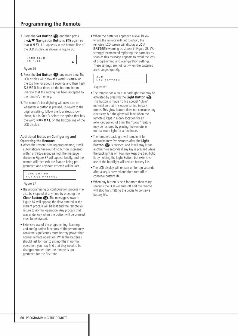
60 PROGRAMMING THE REMOTE
Programming the Remote
3. Press the Set Button F and then pressthe⁄¤ Navigation Buttons E again sothat ONFULL appears in the bottom line ofthe LCD display, as shown in Figure 86.
Figure 86
4. Press the Set Button F one more time. TheLCD display will show the word SAVING onthe top line for about 2 seconds and then flashSAVED four times on the bottom line toindicate that the setting has been accepted bythe remote’s memory.
5. The remote’s backlighting will now turn onwhenever a button is pressed. To revert to theoriginal setting, follow the four steps shownabove, but in Step 3, select the option that hasthe word NORMAL on the bottom line of theLCD display.
Additional Notes on Configuring andOperating the Remote:• When the remote is being programmed, it will
automatically time-out if no button is pressedwithin a thirty-second period. The messageshown in Figure 87 will appear briefly, and theremote will then exit the feature being pro-grammed and any data entered will be lost.
Figure 87
• The programming or configuration process may also be stopped at any time by pressing theClear Button �. The message shown inFigure 87 will appear, the data entered in thecurrent process will be lost and the remote willreturn to normal operation. Any process thatwas underway when the button will be pressedmust be re-started.
• Extensive use of the programming, learningand configuration functions of the remote mayconsume significantly more battery power thannormal remote operation. While the batteriesshould last for four to six months in normaloperation, you may find that they need to bechanged sooner after the remote is pro-grammed for the first time.
• When the batteries approach a level belowwhich the remote will not function, theremote’s LCD screen will display a LOW
BATTERY warning as shown in Figure 88. Westrongly recommend replacing the batteries assoon as this message appears to avoid the lossof programming and configuration settings.These settings are not lost when the batteriesare changed quickly.
Figure 88
• The remote has a built-in backlight that may be activated by pressing the Light Button Q.This button is made from a special “glow”material so that it is easier to find in darkrooms. This glow feature does not consume anyelectricity, but the glow will fade when theremote is kept in a dark location for anextended period of time. The “glow” featuremay be restored by placing the remote innormal room light for a few hours.
• The remote’s backlight will remain lit forapproximately five seconds after the LightButton Q is pressed, and it will stay lit foranother five seconds if any key is pressed whilethe backlight is on. You may keep the backlightlit by holding the Light Button, but extensiveuse of the backlight will reduce battery life.
• The LCD display will remain on for ten secondsafter a key is pressed and then turn off toconserve battery life.
• When any button is held for more than thirtyseconds the LCD will turn off and the remotewill stop transmitting the codes to conservebattery life.
A V R
L O W B A T T E R Y
T I M E O U T O R
C L R K E Y P R E S S E D
B A C K L I G H T
O N F U L L
30362_AVR445_ENG 20/11/06 14:56 Side 60
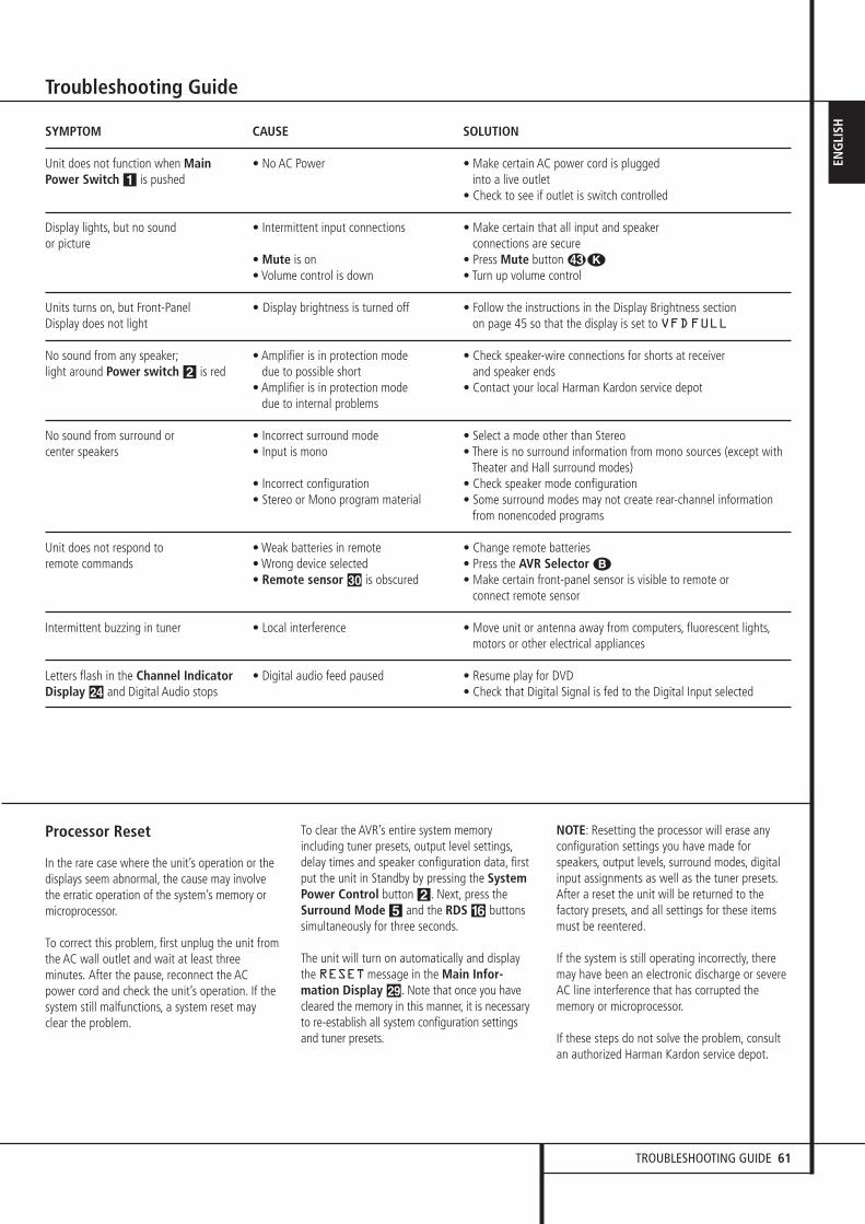
TROUBLESHOOTING GUIDE 61
ENG
LISH
Troubleshooting Guide
Processor Reset
In the rare case where the unit’s operation or thedisplays seem abnormal, the cause may involvethe erratic operation of the system’s memory ormicroprocessor.
To correct this problem, first unplug the unit fromthe AC wall outlet and wait at least threeminutes. After the pause, reconnect the ACpower cord and check the unit’s operation. If thesystem still malfunctions, a system reset mayclear the problem.
To clear the AVR’s entire system memoryincluding tuner presets, output level settings,delay times and speaker configuration data, firstput the unit in Standby by pressing the SystemPower Control button 2. Next, press theSurround Mode 5 and the RDS ^ buttonssimultaneously for three seconds.
The unit will turn on automatically and displaythe RESETmessage in the Main Infor-mation Display ˜. Note that once you havecleared the memory in this manner, it is necessaryto re-establish all system configuration settingsand tuner presets.
NOTE: Resetting the processor will erase anyconfiguration settings you have made forspeakers, output levels, surround modes, digitalinput assignments as well as the tuner presets.After a reset the unit will be returned to thefactory presets, and all settings for these itemsmust be reentered.
If the system is still operating incorrectly, theremay have been an electronic discharge or severeAC line interference that has corrupted thememory or microprocessor.
If these steps do not solve the problem, consultan authorized Harman Kardon service depot.
SYMPTOM CAUSE SOLUTION
Unit does not function when Main • No AC Power • Make certain AC power cord is plugged Power Switch 1 is pushed into a live outlet
• Check to see if outlet is switch controlled
Display lights, but no sound • Intermittent input connections • Make certain that all input and speaker or picture connections are secure
• Mute is on • Press Mute button �K• Volume control is down • Turn up volume control
Units turns on, but Front-Panel • Display brightness is turned off • Follow the instructions in the Display Brightness section Display does not light on page 45 so that the display is set to VFDFULL
No sound from any speaker; • Amplifier is in protection mode • Check speaker-wire connections for shorts at receiver light around Power switch 2 is red due to possible short and speaker ends
• Amplifier is in protection mode • Contact your local Harman Kardon service depotdue to internal problems
No sound from surround or • Incorrect surround mode • Select a mode other than Stereocenter speakers • Input is mono • There is no surround information from mono sources (except with
Theater and Hall surround modes)• Incorrect configuration • Check speaker mode configuration• Stereo or Mono program material • Some surround modes may not create rear-channel information
from nonencoded programs
Unit does not respond to • Weak batteries in remote • Change remote batteriesremote commands • Wrong device selected • Press the AVR Selector B
• Remote sensor ¯ is obscured • Make certain front-panel sensor is visible to remote or connect remote sensor
Intermittent buzzing in tuner • Local interference • Move unit or antenna away from computers, fluorescent lights,motors or other electrical appliances
Letters flash in the Channel Indicator • Digital audio feed paused • Resume play for DVDDisplay Ú and Digital Audio stops • Check that Digital Signal is fed to the Digital Input selected
30362_AVR445_ENG 20/11/06 14:56 Side 61
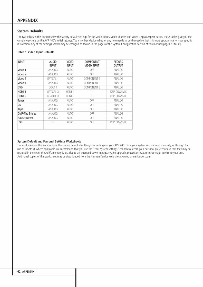
62 APPENDIX
APPENDIX
System DefaultsThe two tables in this section show the factory default settings for the Video Inputs, Video Sources and Video Display Aspect Ratios. These tables give you thecomplete picture on the AVR 445’s initial settings. You may then decide whether any item needs to be changed so that it is more appropriate for your specificinstallation. Any of the settings shown may be changed as shown in the pages of the System Configuration section of this manual (pages 23 to 35).
Table 1: Video Input Defaults
INPUT AUDIO VIDEO COMPONENT RECORD INPUT INPUT VIDEO INPUT OUTPUT
Video 1 ANALOG AUTO OFF ANALOG
Video 2 ANALOG AUTO OFF ANALOG
Video 3 OPTICAL 1 AUTO COMPONENT 1 ANALOG
Video 4 ANALOG AUTO COMPONENT 2 ANALOG
DVD COAX 1 AUTO COMPONENT 3 ANALOG
HDMI 1 OPTICAL 3 HDMI 1 --- DSP DOWNMIX
HDMI 2 COAXIAL 3 HDMI 2 --- DSP DOWNMIX
Tuner ANALOG AUTO OFF ANALOG
CD ANALOG AUTO OFF ANALOG
Tape ANALOG AUTO OFF ANALOG
DMP/The Bridge ANALOG AUTO OFF ANALOG
6/8 CH Direct ANALOG AUTO OFF ANALOG
USB --- AUTO OFF DSP DOWNMIX
System Default and Personal Settings WorksheetsThe worksheets in this section show the system defaults for the global settings on your AVR 445. Once your system is configured manually, or through theuse of EzSet/EQ, where applicable, we recommend that you use the “Your System Settings” column to record your personal preferences so that they may berestored in the event the AVR’s memory is lost due to an extended power outage, system upgrade, processor reset, or other major service to your unit.Additional copies of this worksheet may be downloaded from the Harman Kardon web site at www.harmankardon.com
30362_AVR445_ENG 20/11/06 14:56 Side 62

APPENDIX 63
ENG
LISH
APPENDIX
Worksheet B: Surround Configuration Defaults and Settings
Feature System Default Your System SettingsLogic 7 Global Off
Default Surround Original
Dolby Pro Logic II Music Center Width 3
Dolby Pro Logic II Music Dimension 0
Dolby Pro Logic II Panorama Off
Dolby Pro Logic IIx Music Center Width 3
Dolby Pro Logic IIx Music Dimension 0
Dolby Pro Logic IIx Panorama Off
Night Mode Off
Worksheet C: Delay Defaults and Setting
Feature System Default Your System SettingsFront Left 12.0 Feet
Center 12.0 Feet
Front Right 12.0 Feet
Surround Right 10.0 Feet
Surround Back Right 10.0 Feet
Surround Back Left 10.0 Feet
Surround Left 10.0 Feet
Subwoofers 12.0 Feet
Worksheet D: System Defaults and Settings
Feature System Default Your System SettingsFront L/R Speaker Size & X-Over Small – 100 HzCenter Speaker Size & X-Over Small – 100 HzSurround L/R Speaker Size & X-Over Small – 100 HzSurround Back Speaker Size & X-Over NoneLFE LP Filter 100 Hz
Sub Mode SubChannel Adjust GlobalSub Size 10 in/250 mmVFD Fade Time Out OffVFD Brightness FullVolume Default OffVolume Default Set -25dBSemi OSD Time Out 5 SecFull OSD Time Out 20 SecDMP Auto Power OffSurround Back Amps MainCarrier Out Zone II
30362_AVR445_ENG 20/11/06 14:56 Side 63

64 APPENDIX
APPENDIXFE
ATUR
EDV
DVi
deo
1Vi
deo
2Vi
deo
3Vi
deo
4HD
MI 1
HD
MI 2
CD
Tape
Tune
r Th
e Br
idge
USB
6/8
Ch D
irect
Inpu
t Titl
e
Surr
ound
Mod
e
Audi
o In
Por
t
Audi
o Au
to P
oll
Vide
o In
Por
t
Com
pone
nt V
ideo
Inpu
t
Vide
o Pr
oces
sing
A/V
Sync
Del
ay
Reco
rd O
utpu
t
Auto
Pol
l
ADC
Sam
plin
g
Tone
In/O
ut
Bass
Treb
le
Wor
kshe
et E
:Inp
ut S
etti
ngs
30362_AVR445_ENG 20/11/06 14:56 Side 64
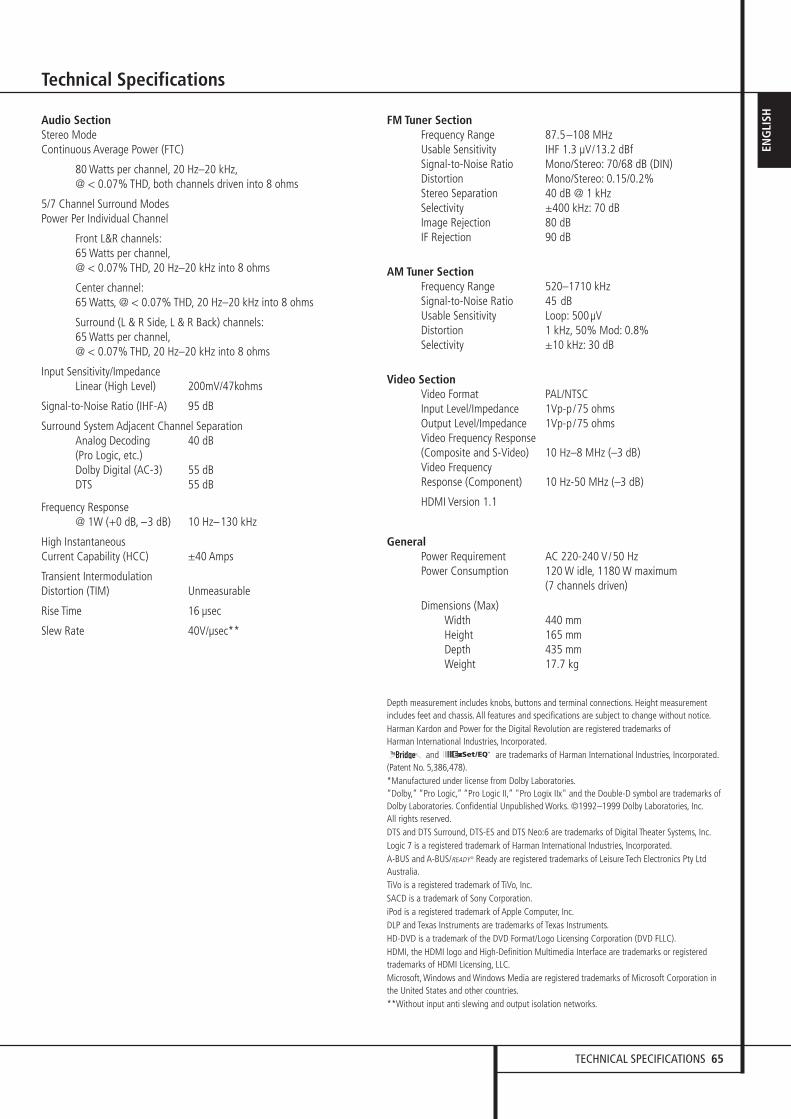
TECHNICAL SPECIFICATIONS 65
ENG
LISH
Technical Specifications
Audio SectionStereo Mode Continuous Average Power (FTC)
80 Watts per channel, 20 Hz–20 kHz,@ < 0.07% THD, both channels driven into 8 ohms
5/7 Channel Surround Modes Power Per Individual Channel
Front L&R channels:65 Watts per channel,@ < 0.07% THD, 20 Hz–20 kHz into 8 ohms
Center channel:65 Watts, @ < 0.07% THD, 20 Hz–20 kHz into 8 ohms
Surround (L & R Side, L & R Back) channels:65 Watts per channel,@ < 0.07% THD, 20 Hz–20 kHz into 8 ohms
Input Sensitivity/Impedance Linear (High Level) 200mV/47kohms
Signal-to-Noise Ratio (IHF-A) 95 dB
Surround System Adjacent Channel Separation Analog Decoding 40 dB (Pro Logic, etc.) Dolby Digital (AC-3) 55 dB DTS 55 dB
Frequency Response @ 1W (+0 dB, –3 dB) 10 Hz–130 kHz
High Instantaneous Current Capability (HCC) ±40 Amps
Transient Intermodulation Distortion (TIM) Unmeasurable
Rise Time 16 µsec
Slew Rate 40V/µsec**
FM Tuner SectionFrequency Range 87.5–108 MHzUsable Sensitivity IHF 1.3 µV/13.2 dBfSignal-to-Noise Ratio Mono/Stereo: 70/68 dB (DIN)Distortion Mono/Stereo: 0.15/0.2%Stereo Separation 40 dB @ 1 kHzSelectivity ±400 kHz: 70 dBImage Rejection 80 dBIF Rejection 90 dB
AM Tuner SectionFrequency Range 520–1710 kHzSignal-to-Noise Ratio 45 dBUsable Sensitivity Loop: 500µVDistortion 1 kHz, 50% Mod: 0.8%Selectivity ±10 kHz: 30 dB
Video SectionVideo Format PAL/NTSCInput Level/Impedance 1Vp-p/75 ohmsOutput Level/Impedance 1Vp-p/75 ohmsVideo Frequency Response(Composite and S-Video) 10 Hz–8 MHz (–3 dB)Video Frequency Response (Component) 10 Hz-50 MHz (–3 dB)
HDMI Version 1.1
GeneralPower Requirement AC 220-240 V/50 HzPower Consumption 120 W idle, 1180 W maximum
(7 channels driven)
Dimensions (Max)Width 440 mm Height 165 mm Depth 435 mm Weight 17.7 kg
Depth measurement includes knobs, buttons and terminal connections. Height measurementincludes feet and chassis. All features and specifications are subject to change without notice.Harman Kardon and Power for the Digital Revolution are registered trademarks of Harman International Industries, Incorporated.
and are trademarks of Harman International Industries, Incorporated.(Patent No. 5,386,478).*Manufactured under license from Dolby Laboratories.“Dolby,” “Pro Logic,” “Pro Logic II,” "Pro Logix IIx" and the Double-D symbol are trademarks ofDolby Laboratories. Confidential Unpublished Works. ©1992–1999 Dolby Laboratories, Inc.All rights reserved.DTS and DTS Surround, DTS-ES and DTS Neo:6 are trademarks of Digital Theater Systems, Inc.Logic 7 is a registered trademark of Harman International Industries, Incorporated.A-BUS and A-BUS/READY® Ready are registered trademarks of Leisure Tech Electronics Pty LtdAustralia.TiVo is a registered trademark of TiVo, Inc.SACD is a trademark of Sony Corporation.iPod is a registered trademark of Apple Computer, Inc.DLP and Texas Instruments are trademarks of Texas Instruments.HD-DVD is a trademark of the DVD Format/Logo Licensing Corporation (DVD FLLC).HDMI, the HDMI logo and High-Definition Multimedia Interface are trademarks or registeredtrademarks of HDMI Licensing, LLC.Microsoft, Windows and Windows Media are registered trademarks of Microsoft Corporation inthe United States and other countries.**Without input anti slewing and output isolation networks.
The Bridge TM
30362_AVR445_ENG 20/11/06 14:56 Side 65

250 Crossways Park Drive, Woodbury, New York 11797 www.harmankardon.comHarman Consumer Group, Inc.:2, route de Tours, 72500 Château-du-Loir, France© 2006 Harman Kardon, Incorporated Part No.: ZKD3201HA00
30362_AVR445_ENG 20/11/06 14:56 Side 66