avr480: anti-pinch system for electrical windo · avr480: anti-pinch system for electrical window...
TRANSCRIPT
7559B–AVR–12/06
Microcontrollers
Application Note
AVR480: Anti-Pinch System for Electrical Window
Automotive motorized window or door apparatus which closes automatically involve
risks for trapping, squeezing or injury to people. They must reverse their movement in
case the force applied by the motor gets higher than one normalized limit. The feature
implies the constant monitoring of the speed, current, position of the glass. For cost
and simplicity reasons, the system described in this application note uses universal
brush motor equipped with hall effect sensors. The detection algorithm is based on
speed derivate and torque and has been verified for robustness and fault tolerance. It
is applicable to all ATMEL AVR® with A to D converter and Interrupt-on-Change I/O.
Powered Equipments in Modern Cars
Today, electronic components and systems account for over 20% of the cost of a high end pas-
senger car. The ability of dense electronics to better control sensors and actuators is utilized to
enhance comfort and safety in cars and it is very predictable that most of the middle and upper
class vehicles will be systematically equipped with motorized window or door systems.
The majority of these equipments come with full automation, means that they must be accompa-
nied by safety systems to prevent people injury or mechanical degradations.
The legislation offers set of rules to which powered systems must comply. This is particularly
true for window lifts or sliding doors. This application note describes how to implement an anti-
pinch algorithm which was initially developed for a powered window but which can be easily
adapted to any other moving part.
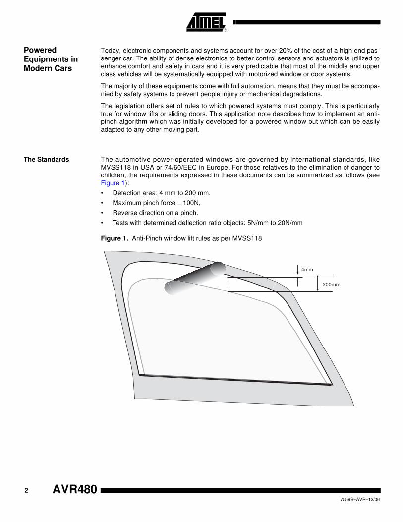
The Standards The automotive power-operated windows are governed by international standards, like
MVSS118 in USA or 74/60/EEC in Europe. For those relatives to the elimination of danger to
children, the requirements expressed in these documents can be summarized as follows (see
Figure 1):
• Detection area: 4 mm to 200 mm,
• Maximum pinch force = 100N,
• Reverse direction on a pinch.
• Tests with determined deflection ratio objects: 5N/mm to 20N/mm
Figure 1. Anti-Pinch window lift rules as per MVSS118
4mm
200mm
2
7559B–AVR–12/06
AVR480

AVR480
Hardware Consideration
Different detection strategies are possible to determine whether an obstacle is entering the criti-
cal pinching area:
• Without mechanical contact. It reacts before the pinch effort is exerted on the object. This is
the optimal protection since no force is applied to the obstacle. It is also independent to
vibration, aerodynamic variations, deformations. But, it requires integrated sensors (infrared,
ultrasonic, ...) with their electronic modules and wires leading to additional costs.
• With mechanical contact. The pressure measurement will tell the system an object is being
pinched. Also there, designers have two fundamental technologies available:
– Direct measurements: Force sensors or contactors are integrated on the door seal.
These solutions are inherently high cost and reduce the styling for window/door
designs
– Indirect measurements via physical monitoring. This is a globally cost optimized
solution.
Anti-Pinch Algorithm Specification
The pinch detection algorithm shall, at first, respect the standards (FMVSS118 & 74/60/EEC)
requirements:
• Detection area from 4 to 200mm
• Maximum exerted force of 100N
• Reverse direction on Pinch detection
• Normalized tests for validation
It has to be adaptive since:
• The mechanical elements involved in the lift system will vary with time (ageing, local
deformation, wear, ...)
• The electrical characteristics could evolve significantly
• The environment will affect the friction forces (temperature, moisture, freeze, etc.)
The system should not react to disturbances neither detect inopportune pinches. It must be
robust against air friction, road vibration, power-cuts, etc...
Solution Using Motor’s Physical Parameters
The force applied to the glass can be extrapolated from the current through the motor. The posi-
tion of the moving elements permanently provides information on speed. Both parameters can
then be used to determine whether an obstacle has been encountered and whether:
• It is in the detection area
• The force applied gets higher than the limit
This document describes one anti-pinch algorithm developed to work with motor current mea-
surements and hall-effect speed indications. With very little changes, it can adapat to other
systems like slidding doors or roof panels.
Modeling, Simulation
To better design the pinch-detection algorithm, the physical parameters involved in the lift sys-
tem have been extracted. Starting from a generic description of an opening/closing aparatus,
one more precise model has been developed for the powered window. It is broken down into
several main components as illustrated in Figure 2.
3
7559B–AVR–12/06

Figure 2. Powered Window Mechanical Components
The identification of the mechanical components leads to consider:
• Motor Effects
– Mechanical Parameters
– Electrical Parameters
• Window-Lift:
– Frictions (limited to slides)
– Machanical non-linearity (coupling mostly)
– Inertia (glass weight)
Motor Model The DC universal motor used can be modeled using a very classical scheme as illustrated in
Figure 3.
Figure 3. DC Motor Equivalent Model
M
Motor
Endless screw
« Flexible »
coupling
Non-linearity
Roller for cable
cable + sheath slides Pulley Cable window fixation
J
f U
i(t)
U
e(t)
L
R
i(t)
4
7559B–AVR–12/06
AVR480
AVR480
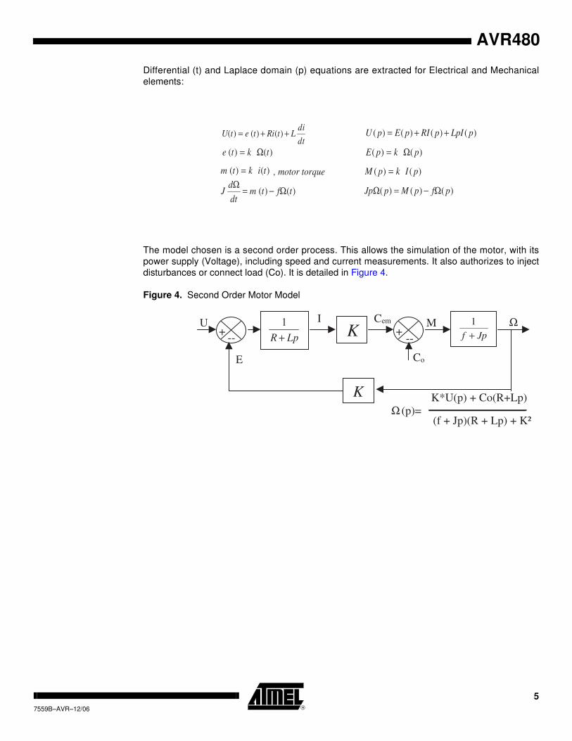
Differential (t) and Laplace domain (p) equations are extracted for Electrical and Mechanical
elements:
The model chosen is a second order process. This allows the simulation of the motor, with its
power supply (Voltage), including speed and current measurements. It also authorizes to inject
disturbances or connect load (Co). It is detailed in Figure 4.
Figure 4. Second Order Motor Model
dt
diLtRitetU ++= )()()( )()()()( pLpIpRIpEpU ++=
)()( tkte Ω= )()( pkpE Ω=
)()( tiktm = , motor torque )()( pIkpM =
)()( tftmdt
dJ Ω−=
Ω
)()()( pfpMpJp Ω−=Ω
LpR +
1K +
-- Jpf +
1
K
+ --
U I Cem
Co
Ω
Ω
E
M
(p)=
K*U(p) + Co(R+Lp)
(f + Jp)(R + Lp) + K²
5
7559B–AVR–12/06
Window-lift Model In addition to the DC motor model, the components from the window-lift system must be
inserted. They are introduced to estimate the torque provided by the motor, and to access to
position, speed and acceleration. The mechanical elements are described in Figure 5.
Figure 5. Window-lift Model
This model is executed to obtain system behavior and to verify the pinch-detection algorithm.
Described parameters and others (static and viscous frictions, weight,...) are tuned and intro-
duced in the model to verify their influence.
Figure 6. Full Window-lift and Pinch-detection Algorithm Model
( )MgFzFzMn
rT sv +++≈
221&&&
M
T
F
1
1
1
T2
2
Weight
F
F
Z
Z
2Z
Mg
n : Gear ratio
r : Radius
T1, T2 : Torque
Fv : Viscous Friction
Fs : Static Friction
n
r
motor
Mechanical
components
sensors Anti-pinch
Algorithm
Pinch &
Disturbances
6
7559B–AVR–12/06
AVR480
AVR480
Pinch Detection Algorithm
Usual pinch-detection algorithm operation is using indirect measurements out of the window-lift
system:
• Current (torque)
• Position (speed)
The algorithm detailed in this document agregates two techniques based on
• Calibrated torque stored in non-volatile memory: Preliminary learning sequence is executed
and torque values are stored in memory. This is quite memory consuming and requires
regular calibration sequences
• Speed derivate calculation: Interesting method since it requires less memory but needs
more computing power
and takes benefit from the two methodologies.
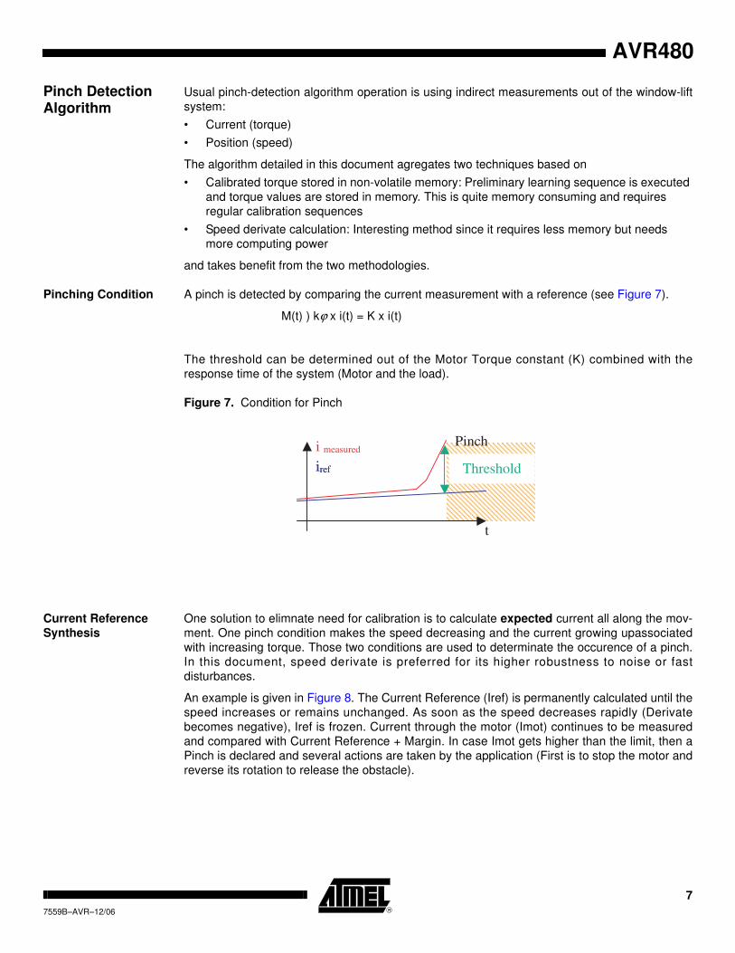
Pinching Condition A pinch is detected by comparing the current measurement with a reference (see Figure 7).
M(t) ) kϕ x i(t) = K x i(t)
The threshold can be determined out of the Motor Torque constant (K) combined with the
response time of the system (Motor and the load).
Figure 7. Condition for Pinch
Current Reference
Synthesis
One solution to elimnate need for calibration is to calculate expected current all along the mov-
ment. One pinch condition makes the speed decreasing and the current growing upassociated
with increasing torque. Those two conditions are used to determinate the occurence of a pinch.
In this document, speed derivate is preferred for its higher robustness to noise or fast
disturbances.
An example is given in Figure 8. The Current Reference (Iref) is permanently calculated until the
speed increases or remains unchanged. As soon as the speed decreases rapidly (Derivate
becomes negative), Iref is frozen. Current through the motor (Imot) continues to be measured
and compared with Current Reference + Margin. In case Imot gets higher than the limit, then a
Pinch is declared and several actions are taken by the application (First is to stop the motor and
reverse its rotation to release the obstacle).
iref
i measured
Threshold
t
iref
Pinch
7
7559B–AVR–12/06

Figure 8. Example of a Pinch detection
Algorithm Robustness
Current Filtering
The permanent calculation of the Iref allows for highly adaptative algorithm. To even increase
the robustness of the alogrithm, the Current Reference is averaged over 8 consecutive mea-
surements (see Figure 9).
Figure 9. Global Current Reference Synthesis Principle
Algorithm Robustness
Blocking points
As Iref permanent calculation allows a highly adaptative algorithm, local great frictions variations
called blocking points could involve bad pinch detection. Indeed, a local friction increase, even-
tually in addition to other disturbances (bumpy road, wind...) could result in a pinch condition, as
Iref would be frozen.
Those blocking points are detected the same way as pinches. The difference between current
and reference is monitored. When it is greater than a threshold, it is detected and blocking point
charateristics are stored into EEPROM.
A blocking point is described only by a position interval and an event counter (number of detec-
tions) to minimize memory requirements. It could be more precise by storing magnitude in the
interval or by using several threshold. But it would use more memory.
A table containing all hard point informations is stored in non volatile memory
When a blocking point is known (stored in table) and its event counter allows to consider it as a
blocking point, the threshold is added to pinch margin, in the correspondig interval, to increase
robustness.
Rotation speed
Derivate speed
Current Imot
Reference Iref
Example: blocking point
When derivate is negative,
reference is frozen
Example: pinching
t
t
t
t
Measured
current ImotAverage (8
samples)
Low pass (2
samples) Exploited current
Derivative speed
Current
Reference Iref
Imeas
8
7559B–AVR–12/06
AVR480
AVR480
Figure 10. Blocking point example
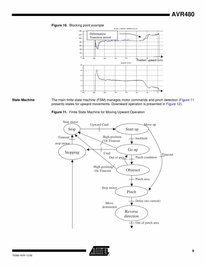
State Machine The main finite state machine (FSM) manages motor commands and pinch detection (Figure 11
presents states for upward movements. Downward operation is presented in Figure 12).
Figure 11. Finite State Machine for Moving Upward Operation
Position: upward (cm)
Deformation:
Transition period
Timeout
Stop Start up
Upward Cmd
backlash
Stopping Cmd
Pinch condition
Obstruct
Pinch
stop motor
Timeout
Out of area
Go up
High position
Or Timeout
High position
Ou Timeout
Pinch area
Reverse
direction
Delay (no current)
Out of pinch area
Stop motor
Move
downward
Move up
Stop motor
9
7559B–AVR–12/06

Figure 12. Downwward Movement Finite State Machine
Adaptation function,
portability
FSM requires parameters (backlash, top and bottom ends, hall sensors resolution...) to work
properly. Those parameters could be constant parameters or measured at initialisation. Some of
them could change from one window lift to another. Thereby, optional adaptation function
acquire those parameters at first initialisation by operating the window lift. It also monitors bloc-
king points to initialize the memorization table.
This optionnal adaptation routine disables anti-pinch while running. It then operates window lift
downward and upward to detect bottom and top positions. Simultaneously, it monitors the block-
ing points. To acquire backlash, It operates downward and upward into the pinch detection area
(by comparing current reference to acquired current).
Other Interesting
Functions
Not described here are secondary functions necessary for Window-lift operation:
• Measuring current, filtering
• Hall-Effect interrupt generation, counting, speed calculation, direction
• Push-button management
• Memorization of critical parameters (position, last operation direction, ...) in case of power-
fail
Stop
Stop motor
Upward Cmd
Stop
request
Cmd
Timeout
Stop motor
Move down
Timeout
Bottom position Or Timeout
Calibrate / Init of the position
Move downward
10
7559B–AVR–12/06
AVR480

AVR480
Simulation Results Numerous simulations have be ran to assess and tune the different parameters for the detection
threshold loop. Figure 13 visualizes how the speed and motor torque behave at the first and sec-
ond ‘go-upward’ commands. Also, a pinch condition is injected at t=10s with a compression
spring of 10N/mm.
Figure 14 shows the same curves but disturbances in motor torque are injected (frequency of
10Hz, 50N), after a second ‘go-upward’ command.
Figure 13. Simulation of the Algorithm with two Consecutive ‘Go-Upward’ Commands
1. The non-linearity of the transmission causes a speed overvalue at motor start. The torque
looks like un-coupled for a few moment.
2. There, the elasticity of the transmission system is no more involved and the torque and speed
images are different.
1* 2*
1* 2*
Motor speed (seen from window: dm/s)
Pinch Force (N)
Current (A)* acquisition gain, after average and reference.
Reverse direction
Pinching
Current – Reference
> Threshold
t
t
t
11
7559B–AVR–12/06
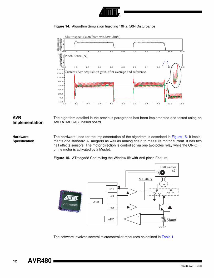
Figure 14. Algorithm Simulation Injecting 10Hz, 50N Disturbance
AVR Implementation
The algorithm detailed in the previous paragraphs has been implemented and tested using an
AVR ATMEGA88 based board.
Hardware
Specification
The hardware used for the implementation of the algorithm is described in Figure 15. It imple-
ments one standard ATmega88 as well as analog chain to measure motor current. It has two
hall effects sensors. The motor direction is controlled via one two-poles relay while the ON-OFF
of the motor is activated by a Mosfet.
Figure 15. ATmega88 Controlling the Window-lift with Anti-pinch Feature
The software involves several microcontroller resources as defined in Table 1.
Current (A)* acquisition gain, after average and reference.
Pinch Force (N)
Motor speed (seen from window: dm/s)
Shunt
V Battery
M
-
+
Hall Sensor
x2
AVR
ADC
INT
out
out
12
7559B–AVR–12/06
AVR480

AVR480
Task Scheduling By considering, the algorithm described previously, as well as the allocation of hardware and
software resources, we obtain the following scheduling of the program
Normal Operations This schedule is valid when the algorithm is running in standard operating condition, i.e. when
the motor is operating (rotating) or is stopped. Indeed, position, speed and reference calcula-
tions are refreshed when events occurs from the position sensors (hall effect sensors) or don't
have to be done (when the motor is stopped in a stable and normal state).
Figure 16. Task Scheduling When Normal Operation
Table 1. Hardware / Software Partitioning
Feature A to D
Converter
Timer0
(8-bit)
Timer1
(16-bit)
PCINT9 EEPROM IDLE
(Soft)
Current Acquisition X X
Position, Speed,
direction
X x
Determine Current
Reference
X X
Timeout X
Save Parameters X X
Filter X
Anti-Pinching X
Operate Window-Lift X
Timer 1 overflow interrupt
Computation of position, derivate speed,
current reference
Edge on position sensor
PCINT9 interrupt
Timer 0 overflow
Idle
Filtering, Window-lift operations, Anti-pinching…
Reset of timer counter
ADC : Current acquisition
13
7559B–AVR–12/06
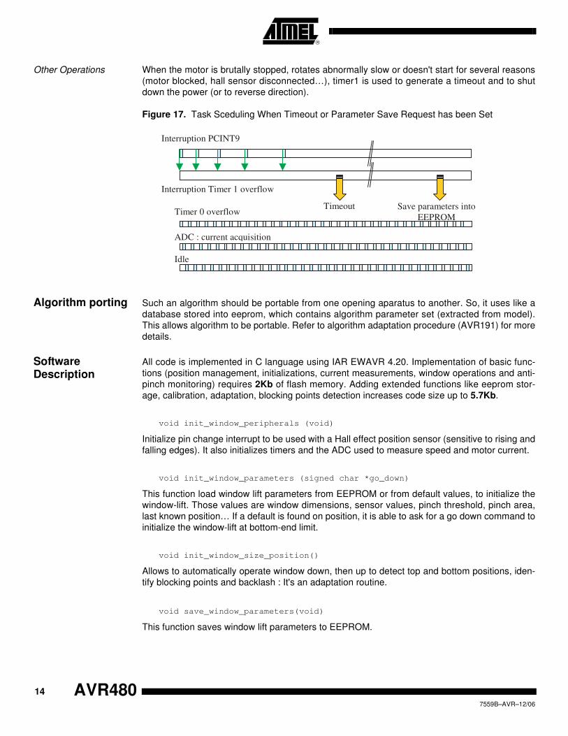
Other Operations When the motor is brutally stopped, rotates abnormally slow or doesn't start for several reasons
(motor blocked, hall sensor disconnected…), timer1 is used to generate a timeout and to shut
down the power (or to reverse direction).
Figure 17. Task Sceduling When Timeout or Parameter Save Request has been Set
Algorithm porting Such an algorithm should be portable from one opening aparatus to another. So, it uses like a
database stored into eeprom, which contains algorithm parameter set (extracted from model).
This allows algorithm to be portable. Refer to algorithm adaptation procedure (AVR191) for more
details.
Software Description
All code is implemented in C language using IAR EWAVR 4.20. Implementation of basic func-
tions (position management, initializations, current measurements, window operations and anti-
pinch monitoring) requires 2Kb of flash memory. Adding extended functions like eeprom stor-
age, calibration, adaptation, blocking points detection increases code size up to 5.7Kb.
void init_window_peripherals (void)
Initialize pin change interrupt to be used with a Hall effect position sensor (sensitive to rising and
falling edges). It also initializes timers and the ADC used to measure speed and motor current.
void init_window_parameters (signed char *go_down)
This function load window lift parameters from EEPROM or from default values, to initialize the
window-lift. Those values are window dimensions, sensor values, pinch threshold, pinch area,
last known position… If a default is found on position, it is able to ask for a go down command to
initialize the window-lift at bottom-end limit.
void init_window_size_position()
Allows to automatically operate window down, then up to detect top and bottom positions, iden-
tify blocking points and backlash : It's an adaptation routine.
void save_window_parameters(void)
This function saves window lift parameters to EEPROM.
Timer 0 overflow
ADC : current acquisition
Idle
Interruption PCINT9
Interruption Timer 1 overflow
Timeout Save parameters into
EEPROM
14
7559B–AVR–12/06
AVR480

AVR480
U8 window_ctrl (signed char *up_cmde, signed char *down_cmde ,U8
no_anti_pinch)
This contains the window-lift state machine. It controls window operations, with given events
parameters. It monitors the position, up and down end limits, and the anti-pinching condition. It
returns the state of the window-lift (same value as the get_window_state function).
__interrupt void hall_sensor_ISR (void)
This interrupt sub-routine is executed on hall sensor edges. It computes rotation direction, posi-
tion, derivative speed and motor current reference.
It's also able to detect a default on a hall effect sensor (which is not connected to an interrupt
pin) by counting successive direction changes. It is used to force the window to stop after a
defined step.
__interrupt void TIMER0_OVF_ISR (void)
This interrupt sub-routine is executed on timer 0 overflow to shedule ADC conversion starting.
signed char get_window_state (void)
It returns the state of the window-lift state machine (value used in the window_ctrl function).
signed char force_window_state (signed char temp)
Set-up window-lift state: useful to force operations (stop request…).
unsigned char mean (unsigned char)
Compute a mean on the 8 last samples. Used for filtering motor current.
void push_button (signed char *push)
This function monitors a push button and generates operation command events to be transmit-
ted to the window_ctrl function.
U8 blocking_point(signed char window_state)
This function monitors blocking points by comparing current value with reference. It shall be syn-
chronized with window control state machine. So, it requires window_ctrl to be called before and
its returned state shall be provided in parameter.
U8 update_point (void)
This function shall be called by blocking_point routine to sort, create or refresh blocking points
data table when a blocking point has just been completly detected. When this blocking point was
existing, it updates its event counter and its position interval. If it wasn’t existing, routine insert it
in the blocking points table.
void clean_point(void)
This routine shall be called by blocking_point routine and the end of each upward operation.
It’s in charge of decreasing blocking point event counter in the parsed area. It cleans blocking
points which event counter has decreased to zero (means they no more exists or it was a distur-
bance or a pinch and have no more been detected)
15
7559B–AVR–12/06
U8 get_block_point(U16 position)
This function returns the corresponding threshold value to add to pinch margin value if a block-
ing point has been confirmed at the provided position in parameter. Otherwise, when there are
no blocking point at this postion, it returns zero.
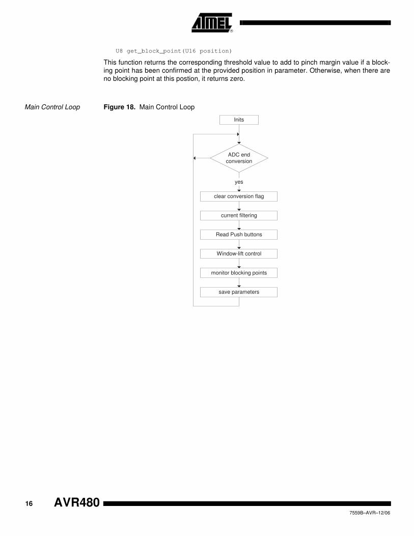
Main Control Loop Figure 18. Main Control Loop
ADC endconversion
Inits
clear conversion flag
current filtering
yes
Read Push buttons
Window-lift control
monitor blocking points
save parameters
16
7559B–AVR–12/06
AVR480
AVR480
Hall effect Position
Sensor Interrupt Sub-
routine
Figure 19. Hall effect Position Sensor Interrupt Sub-routine
Hall sensor ISR
save timer content
Direction ?
decrement position increment position
upward
downward
Default ?
stop request
yes
dv > 0 orref < current
compute derivative speed (dv)
update current reference
yes
end ISR
17
7559B–AVR–12/06
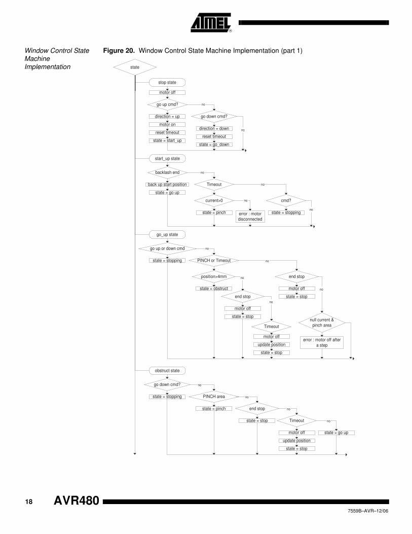
Window Control State
Machine
Implementation
Figure 20. Window Control State Machine Implementation (part 1)
state
stop state
motor off
go up cmd?
direction = up
motor on
go down cmd?
direction = down
no
state = start_upstate = go_down
reset timeoutreset timeout
start_up state
backlash end
state = pinch
Timeout
state = go up
no
back up start position
current>0
no
cmd?
error : motordisconnected
no
no
state = stoppingno
go_up state
go up or down cmd
state = stopping PINCH or Timeout
no
position>4mm
state = obstruct
end stop
no
motor off
state = stop
Timeout
no
update position
motor off
state = stop
end stop
no
motor off
state = stop
null current &pinch area
error : motor off aftera step
no
obstruct state
go down cmd?
state = stopping PINCH area
no
state = pinch end stop
no
state = stop Timeout
update position
motor off
state = stop
no
no
state = go up
18
7559B–AVR–12/06
AVR480
© Atmel Corporation 2006. All rights reserved. Atmel®, logo and combinations thereof, are registered trademarks, and Everywhere You Are®
are the trademarks of Atmel Corporation or its subsidiaries. Other terms and product names may be trademarks of others.
Disclaimer: The information in this document is provided in connection with Atmel products. No license, express or implied, by estoppel or otherwise, to any intellectual property right is granted by this document or in connection with the sale of Atmel products. EXCEPT AS SET FORTH IN ATMEL’S TERMS AND CONDI-TIONS OF SALE LOCATED ON ATMEL’S WEB SITE, ATMEL ASSUMES NO LIABILITY WHATSOEVER AND DISCLAIMS ANY EXPRESS, IMPLIED OR STATUTORY WARRANTY RELATING TO ITS PRODUCTS INCLUDING, BUT NOT LIMITED TO, THE IMPLIED WARRANTY OF MERCHANTABILITY, FITNESS FOR A PARTICULAR PURPOSE, OR NON-INFRINGEMENT. IN NO EVENT SHALL ATMEL BE LIABLE FOR ANY DIRECT, INDIRECT, CONSEQUENTIAL, PUNITIVE, SPECIAL OR INCIDEN-TAL DAMAGES (INCLUDING, WITHOUT LIMITATION, DAMAGES FOR LOSS OF PROFITS, BUSINESS INTERRUPTION, OR LOSS OF INFORMATION) ARISING OUT OF THE USE OR INABILITY TO USE THIS DOCUMENT, EVEN IF ATMEL HAS BEEN ADVISED OF THE POSSIBILITY OF SUCH DAMAGES. Atmel makes no representations or warranties with respect to the accuracy or completeness of the contents of this document and reserves the right to make changes to specifications and product descriptions at any time without notice. Atmel does not make any commitment to update the information contained herein. Unless specifically providedot-herwise, Atmel products are not suitable for, and shall not be used in, automotive applications. Atmel’sAtmel’s products are not intended, authorized, or warranted for use as components in applications intended to support or sustain life.
Atmel Corporation Atmel Operations
2325 Orchard Parkway
San Jose, CA 95131, USA
Tel: 1(408) 441-0311
Fax: 1(408) 487-2600
Regional Headquarters
Europe
Atmel Sarl
Route des Arsenaux 41
Case Postale 80
CH-1705 Fribourg
Switzerland
Tel: (41) 26-426-5555
Fax: (41) 26-426-5500
Asia
Room 1219
Chinachem Golden Plaza
77 Mody Road Tsimshatsui
East Kowloon
Hong Kong
Tel: (852) 2721-9778
Fax: (852) 2722-1369
Japan
9F, Tonetsu Shinkawa Bldg.
1-24-8 Shinkawa
Chuo-ku, Tokyo 104-0033
Japan
Tel: (81) 3-3523-3551
Fax: (81) 3-3523-7581
Memory
2325 Orchard Parkway
San Jose, CA 95131, USA
Tel: 1(408) 441-0311
Fax: 1(408) 436-4314
Microcontrollers
2325 Orchard Parkway
San Jose, CA 95131, USA
Tel: 1(408) 441-0311
Fax: 1(408) 436-4314
La Chantrerie
BP 70602
44306 Nantes Cedex 3, France
Tel: (33) 2-40-18-18-18
Fax: (33) 2-40-18-19-60
ASIC/ASSP/Smart Cards
Zone Industrielle
13106 Rousset Cedex, France
Tel: (33) 4-42-53-60-00
Fax: (33) 4-42-53-60-01
1150 East Cheyenne Mtn. Blvd.
Colorado Springs, CO 80906, USA
Tel: 1(719) 576-3300
Fax: 1(719) 540-1759
Scottish Enterprise Technology Park
Maxwell Building
East Kilbride G75 0QR, Scotland
Tel: (44) 1355-803-000
Fax: (44) 1355-242-743
RF/Automotive
Theresienstrasse 2
Postfach 3535
74025 Heilbronn, Germany
Tel: (49) 71-31-67-0
Fax: (49) 71-31-67-2340
1150 East Cheyenne Mtn. Blvd.
Colorado Springs, CO 80906, USA
Tel: 1(719) 576-3300
Fax: 1(719) 540-1759
Biometrics/Imaging/Hi-Rel MPU/
High Speed Converters/RF Datacom
Avenue de Rochepleine
BP 123
38521 Saint-Egreve Cedex, France
Tel: (33) 4-76-58-30-00
Fax: (33) 4-76-58-34-80
Literature Requests
www.atmel.com/literature
Printed on recycled paper.
7559B–AVR–12/06