avst morphing project research summaries in fiscal …mln/ltrs-pdfs/nasa-2002-tm211769.pdf · ·...
TRANSCRIPT

August 2002
NASA/TM-2002-211769
AVST Morphing Project ResearchSummaries in Fiscal Year 2001
Anna-Maria R. McGowanLangley Research Center, Hampton, Virginia

The NASA STI Program Office ... in Profile
Since its founding, NASA has been dedicated tothe advancement of aeronautics and spacescience. The NASA Scientific and TechnicalInformation (STI) Program Office plays a keypart in helping NASA maintain this importantrole.
The NASA STI Program Office is operated byLangley Research Center, the lead center forNASA’s scientific and technical information. TheNASA STI Program Office provides access to theNASA STI Database, the largest collection ofaeronautical and space science STI in the world.The Program Office is also NASA’s institutionalmechanism for disseminating the results of itsresearch and development activities. Theseresults are published by NASA in the NASA STIReport Series, which includes the followingreport types:
• TECHNICAL PUBLICATION. Reports ofcompleted research or a major significantphase of research that present the results ofNASA programs and include extensivedata or theoretical analysis. Includescompilations of significant scientific andtechnical data and information deemed tobe of continuing reference value. NASAcounterpart of peer-reviewed formalprofessional papers, but having lessstringent limitations on manuscript lengthand extent of graphic presentations.
• TECHNICAL MEMORANDUM. Scientificand technical findings that are preliminaryor of specialized interest, e.g., quick releasereports, working papers, andbibliographies that contain minimalannotation. Does not contain extensiveanalysis.
• CONTRACTOR REPORT. Scientific andtechnical findings by NASA-sponsoredcontractors and grantees.
• CONFERENCE PUBLICATION. Collectedpapers from scientific and technicalconferences, symposia, seminars, or othermeetings sponsored or co-sponsored byNASA.
• SPECIAL PUBLICATION. Scientific,technical, or historical information fromNASA programs, projects, and missions,often concerned with subjects havingsubstantial public interest.
• TECHNICAL TRANSLATION. English-language translations of foreign scientificand technical material pertinent to NASA’smission.
Specialized services that complement the STIProgram Office’s diverse offerings includecreating custom thesauri, building customizeddatabases, organizing and publishing researchresults ... even providing videos.
For more information about the NASA STIProgram Office, see the following:
• Access the NASA STI Program Home Pageat http://www.sti.nasa.gov
• E-mail your question via the Internet [email protected]
• Fax your question to the NASA STI HelpDesk at (301) 621-0134
• Phone the NASA STI Help Desk at(301) 621-0390
• Write to:NASA STI Help DeskNASA Center for AeroSpace Information7121 Standard DriveHanover, MD 21076-1320

National Aeronautics andSpace Administration
Langley Research CenterHampton, Virginia 23681-2199
August 2002
NASA/TM-2002-211769
AVST Morphing Project ResearchSummaries in Fiscal Year 2001
Anna-Maria R. McGowanLangley Research Center, Hampton, Virginia

Available from:
NASA Center for AeroSpace Information (CASI) National Technical Information Service (NTIS)7121 Standard Drive 5285 Port Royal RoadHanover, MD 21076-1320 Springfield, VA 22161-2171(301) 621-0390 (703) 605-6000
Acknowledgments
The author gratefully acknowledges the invaluable, cross-disciplinary technical leadership of theMorphing Project team who are the primary reason for the success stories in Morphing in fiscalyear 2001. Drs. Darrel Tenney and Richard Antcliff, and Messrs. Thomas Sutter and Long Yiphave also provided crucial guidance throughout the year. The dependable support ofMss. Sherry Cox, Frances Sabo, and Pamela Stacy has also been essential to the Morphingproject and are sincerely appreciated.

1
Abstract
The Morphing project at the National Aeronautics and Space Agency’s Langley Research Centeris part of the Aerospace Vehicle Systems Program Office that conducts fundamental research onadvanced technologies for future flight vehicles. The objectives of the Morphing project are todevelop and assess advanced technologies and integrated component concepts to enable efficient,multi-point adaptability in air and space vehicles. In the context of the project, the word“morphing” is defined as “efficient, multi-point adaptability” and may include micro or macro,structural or fluidic approaches. The current document on the Morphing project is a compilationof research summaries and other information on the project from fiscal year 2001. The focus ofthis document is to provide a brief overview of the project content, technical results and lessonslearned from fiscal year 2001.

2

3
Table of Contents
Abstract.......................................................................................................................................1
Introduction ................................................................................................................................5
Work Packages and Lead Researchers in Fiscal Year 2001 in the Morphing Project ............8
Micro-Aero Adaptive Control FY 2001 Research Summaries ...............................................10
Periodic Excitation for Forebody Vortex Control ...........................................................11
Virtual Shape Change Research .......................................................................................13
Fluidic Thrust Vectoring for Control ...............................................................................15
Active Control and Prediction of Jet Noise ......................................................................17
Closed-Loop Control of Cavity Shear-Layer Instabilities ...............................................19
Simplified High Lift System..............................................................................................21
Smart Surfaces for Drag Reduction .................................................................................24
Active Transonic Drag Reduction Through Shock Spreading ........................................26
Unsteady Circulation Control for Enhanced Vehicle Performance ................................28
Advanced Sensors for Flow Control .................................................................................30
Actuator Development for Micro Aero Adaptive Control (MAAC) ...............................32
Smart Technologies FY 2001 Research Summaries ................................................................34
Electroactive Polymers and Modeling of Electroactive Materials...................................35
Flex Circuits And Cables ..................................................................................................37
Microwave-Driven Smart Membrane Actuators .............................................................39
MDO Techniques and Novel Aircraft Control Systems...................................................43
Flight Control Technologies for Adaptive Aerospace Vehicles .......................................45
Adaptive Structural Morphing FY 2001 Research Summaries..............................................48
Biomimetics Ways to Create Efficient Multifunctional Structures.................................49
Adaptive Wing Structural Concepts.................................................................................51
High-Rate, Morphable, Hingeless Control Surface Demonstrated in the TDT ..............53
Sampson - Smart Aircraft and Marine Projects System Demonstration........................56
Langley Adaptive Aeroelastic Demonstrator ...................................................................59
Elastic Tailoring and Active Control of Wing Structures ...............................................61
Multifunctional Adaptive Structures................................................................................63
Synergistic Tailored Design of Metals and Structures.....................................................65

4
Autonomous Adaptive Control Systems...........................................................................67
Feedback Control Using Piezoelectric Actuators: Do’s and Don’ts ...............................69
Probabilistic Approach to Model Update of the Aerostructures Test Wing (ATW) ......71
Aerostructures Test Wing (ATW) Excitation System Design and Performance Test ....73
Development of a Self-Sensing Piezoelectric Actuator.....................................................75
Biologically-Inspired Flight Systems FY 2001 Research Summaries ....................................77
Biologically-Inspired Flight Concepts ..............................................................................78
Autonomous/Collaborative Control of Aeroelastic Fixed Wing Micro Aerial Vehicles:Characteristics of Fixed Wing Micro-UAVs ....................................................................80
Component Technologies ..................................................................................................83
Airmass Guidance .............................................................................................................85
Dynamics and Control of Resonant Flapping Micro-Aerial Vehicles .............................87
Biosant FY 2001 Research Summary ......................................................................................90
Biologically Inspired Fabrication of Electroactive MAV Wings .....................................91
Appendix...................................................................................................................................94
Morphing Project Team FY 2001 ............................................................................................95
Formal Publications .................................................................................................................96
2001 Institute For Computer Applications in Science and Engineering (ICASE) ...............102
Lecture Series on Morphing...................................................................................................102
Partnerships and Collaborations in the Morphing Project in Fiscal Year 2001 ..................103

5
Introduction
The Aerospace Vehicle Systems Technology (AVST) Program office of the NASA Office ofAero-Space Technology has been developing coordinated research programs in which individualdisciplines are supported in a collaborative environment to foster the development ofbreakthrough technologies. As part of AVST, the object of the Morphing project at the NASALangley Research Center (LaRC) are to develop and assess advanced technologies and integratedcomponent concepts to enable efficient, multi-point adaptability in air and space vehicles. Thisis accomplished by integrating smart, biologically-inspired, or other innovative approaches thatlead to aggressive improvements in the adaptability, efficiency and safety of future flightvehicles. These improvements enable (1) improved vehicle resilience to safely addressunforeseen problems; (2) extensive versatility to efficiently accommodate contrasting missionrequirements; (3) and enhanced performance resulting in reduced operating costs. Additionally,technologies developed in the Morphing project may expose new capabilities and missionscenarios for future aircraft and spacecraft.
The Morphing project is an inherently multidisciplinary project, and has been built around a corediscipline-based structure to provide the fundamental technology base. The key disciplines inthe project include materials, structures, controls, flow physics, multidisciplinary optimization,biology, and electronics. The discipline-based research activities are integrated to support theproject application areas that include micro-aero adaptive control, adaptive structural morphing,and biologically-inspired flight systems (see figure 1). Smart and biologically-inspiredtechnologies and advanced component concepts are currently under development for eachapplication area. In some cases, the technologies are consolidated into devices that have localsensing and feedback control. For many applications, these devices will modify localphenomena to support a macroscopic strategy, such as flow separation control for advanced highlift systems. Consequently, a combined approach to control systems and system identification isbeing used in the Morphing project to address the control laws and controller responses requiredfor the individual devices, as well as addressing global requirements for distributed arrays ofdevices to achieve an overall system benefit. At the system level, multidisciplinary designoptimization will take advantage of the tools developed in the program to optimize thecomponent technologies and provide a systems approach to component integration.

6
Figure 1. Major components of the fiscal year 2001 Morphing Project
This document provides a compilation of summaries of the research conducted in the Morphingproject in Fiscal Year (FY) 2001. Each summary was written by the lead researcher of a specificresearch effort (called a work package). The lead researcher should be contacted directly formore detailed information on any work package. Other documentation that provides broadoverviews of the past and present project is references i. The current document begins with asummary of the organization of the research in FY 2001, followed by the research summaries.The Appendix contains a listing of formal publications, invited lecturers, external organizationsand the Morphing project team in FY 2001. The focus of the current document is the technicalresults and lessons learned of the project in FY 2001. A project plan with milestones is availableupon request.
The Morphing Project in Fiscal Year 2001In fiscal year 2001, all research activities in the Morphing project were organized into five areas:Micro-Aero-Adaptive Control, Smart Technologies, Adaptive Structural Morphing, BiologicallyInspired Flight Systems and BIOSANT (which is jointly managed with the SLMFST Project inAVST). Each project area included several work packages as shown in Table 1. In FY 2001, theMorphing project included approximately 70 person years of effort and had a gross budget of$10.6M. Due to the multidisciplinary nature of the project, over 34 different branches at NASALangley Research Center and one branch from NASA Dryden Flight Research Center were
AdaptiveStructuralMorphing
Micro-AeroAdaptiveControl
Biologically-Inspired Flight Systems
Revolutionary SmartMaterials
Biomimetic MaterialsNanotechnology
OptimizationControls
Electronics
Multifunctionall Adaptive Lifting Surfaces
Learning from Nature
Global FlowfieldControl withMicro Inputs

7
involved in the project in FY 2001. In addition, in FY 2001, the project incorporated numerouscollaborative research efforts with external organizations. A complete listing of the externalorganizations is provided in the Appendix. A lecture series on morphing related topics wasinitiated in FY 2001 to broaden our knowledge and foster further interactions with externalresearchers. A listing of the lectures is also provided in the Appendix.
i 3, 27, 28, 55, 59

8
Work Packages and Lead Researchers in Fiscal Year 2001 in the Morphing Project
Micro-Aero Adaptive Control - Anthony E. WashburnManeuvering Control
Periodic Excitation for Forebody VortexControl
D. Bruce Owens
Virtual Shape Change Research Fang-Jeng ChenFluidic Thrust Vectoring Larry Leavitt
Noise AttenuationActive Control and Prediction of Jet Noise Kevin W. KinzieClosed-Loop Control of Cavity Shear-Layer Instabilities
Michael A. Kegerise
Performance EnhancementSimplified High Lift System LaTunia PackSmart Surfaces for Drag Reduction Michael WalshActive Transonic Drag Reduction ThroughShock Spreading
Maria BobskillWilliam E. Millholen
Fundamental Tool DevelopmentAdvanced Sensors for Flow Control Kenneth WrightActuator Development for MAAC Norman W. Schaeffler
Smart Technologies - Robert G. BryantElectroactive Polymers and Modeling ofElectroactive Materials
Joycelyn Harrison
Flex Circuits and Cables Kevin N. BarnesMicrowave-driven Smart MembraneActuators
Sang H. Choi
Performance Characterization and DesignOptimization of Macro-Fiber CompositeActuators
W. Keats Wilkie
MDO Techniques and Novel AircraftControl Systems
Sharon L. Padula
Flight Control Technologies for AdaptiveAerospace Vehicles
David Raney
Adaptive Structural Morphing - Lucas G. HortaSmart/Bio-Inspired Concepts
Biomimetics Ways to Create EfficientMultifunctional Structures
Dawn Jegley
Adaptive Wing Structural Concepts Thomas JordanHigh-Rate, Morphable, Hingeless ControlSurface Demonstrated in the TDT
Jennifer P. Florance
SAMPSON-Smart Aircraft and MarineProjects System Demonstration
Jeffrey D. Flamm

9
Wind Tunnel Performance EvaluationLangley Adaptive AeroelasticDemonstrator
Robert Scott
Structures Technology DevelopmentElastic Tailoring and Active Control ofWing Structures
David M. McGowan
Multifunctional Adaptive Structures Travis L. TurnerSynergistic Tailored Design of Metals andStructures
Kimberly S. Bey
Autonomous Adaptive Control Systems Randolph CabellModeling/Validation
Feedback Control Using PiezoelectricActuators: Do’s and Don’ts
Lucas G. HortaMercedes C. Reaves
Probabilistic Approach to Model Update ofthe Aerostructures Test Wing (ATW)
Lucas G. HortaMercedes C. ReavesDavid F. Voracek
Aerostructures Test Wing (ATW)Excitation system Design and PerformanceTest
Mercedes C. ReavesLucas G. HortaDavid F. Voracek
Development of a Self-SensingPiezoelectric Actuator
Lucas G. HortaMercedes C. ReavesGarnett C. Horner
Biologically-Inspired Flight Systems - David E. CoxBiomimetic Long Endurance Vehicle Systems
Biologically-Inspired Flight Concepts Barry LazosAutonomous/Collaborative Control ofAeroelastic Fixed Wing Micro AerialVehicles: Characteristics of Fixed WingMicro-UAVs
Marin R. Waszak
Component Technologies Robert FoxQamar Shams
Swarming and Airmass GuidanceAirmass Guidance David E. Cox
Aerodynamics and Control of Flapping FlightDynamics and Control of ResonantFlapping Micro-Aerial Vehicles
David Raney
BIOSANT - Emilie J. SiochiBIOSANT (Joint effort with the SLMFST project)
Biologically-Inspired Fabrication ofElectroactive MAV Wings
Emilie J. Siochi
Table 1. Work Packages and Lead Researchers in Fiscal Year 2001 in the Morphing Project

10
Micro-Aero Adaptive Control FY 2001 Research Summaries

11
Periodic Excitation for Forebody Vortex Control
D. Bruce Owens, 757-864-8450, [email protected] Dynamics Branch, Airborne Systems Competency
Background Information:At a significant angle-of-attack, a forebody will shed vortices. If the forebody is some distancefrom the center-of-gravity, mechanical and continuous blowing pneumatic devices have shownthat these vortices can be manipulated to produce favorable yawing moments.
Objective of Current Work:To evaluate the use of advanced fluidic effectors which use the technique of periodic excitationfor the purpose of forebody fluidic control in a simple, lightweight, and seamless manner foraerospace vehicles. The yaw control produced by manipulating the forebody vortex flow fieldwill be shown to provide control power for enhanced maneuvering and stability augmentation.
Benefits over Existing Systems:This research uses active flow control to manipulate the forebody vortices. The benefit overprevious methods would possibly be easier system integration and lower power requirements.
Previous Work on This Work Package:During FY 2000, an existing generic fighter model was modified to accept a synthetic jetactuator into the chined forebody. The characterization of the actuator mounted on the twodifferent types of nozzles (normal and tangential blowing) was accomplished using a hot wireanemometer, and the velocity fields around the actuator/nozzle configurations were documentedat a wind-off condition, and the actuator frequency effects were also measured and documented.Wind tunnel testing was conducted in the 12-Foot Low-Speed Tunnel. These tests showed,using a flow visualization technique, that blowing using the synthetic jet was able to create anasymmetric vortex flow field around the forebody of the model. Surface pressure measurementsconfirmed the flow asymmetry. However, no measurable yawing moment coefficient wasproduced.
Current Year Accomplishments:During FY 2001 a smooth round forebody for a different but comparable generic fighter hasbeen designed and built that incorporates a new actuator that should produce higher velocitiesand flow rates. The forebody is designed with numerous parameters, e.g., blowing location bothcircumferentially and longitudinally, blowing direction, nozzle size and shape, forebody apexshape - rounded to pointed, fineness ratio, multiple simultaneous blowing locations.Instrumentation for the model will include: standard six-component strain gauge balance, steadyand unsteady pressure measurements on the forebody. This model will be tested during theOctober-November 2001 timeframe in the 12-Foot Low-Speed Wind Tunnel and the March 2002timeframe.
Lessons Learned:As there was no wind tunnel testing performed during FY 2001 this section is not applicable.

12
Future Work:If the present research is successful then future research will include placing these morphingdevices in a free-flying generic fighter model. The free-flight technique will allow for theevaluation of the stability and control authority offered by the devices in a six-degree of freedomenvironment. This future research will also include control law design and possible additionalstatic and dynamic wind tunnel tests to refine the characterization of the devices.

13
Virtual Shape Change Research
Dr. Fang-Jenq (Frank) Chen, 747-864-5732, [email protected] Physics and Controls Branch, Aerodynamics, Aerothermodynamics and
Acoustics Competency
Background Information:Conventional airfoils of aerospace vehicles have been designed for a single flight condition andthen modified to cover multiple flight conditions. This is done through the use of controlsurfaces, such as ailerons and flaps. The control surfaces affect changes in the flow field bydirectly varying the camber on certain regions of the airfoil, thereby causing changes in thestructural and aerodynamic characteristics of the entire airfoil.
Objective of Current Work:The primary objective of virtual shape change research is to develop a cost-effective flow controlsystem that has the potential for revolutionary advances in aerodynamic performance andmaneuvering compared to conventional approaches.
Benefits over Existing Systems:The development of such systems has many implications for aerospace vehicles including:reduced mechanical complexity, lower energy consumption, enhanced maneuvering, and agilitywith enhanced aerodynamic performance and safety.
Previous Work on this Work Package:Previous work on this work package was to develop powerful synthetic jets for practical flowcontrol applications. To date, the velocities generated from the LaRC synthetic jet actuator areamong the largest in the world. Details of the characteristics and performance of the LaRCsynthetic jet actuator had been investigated and documented.
Current Year Accomplishments:A two-dimensional NACA 0015 airfoil model was designed to test mild maneuvering capabilityof synthetic jets in the NASA Langley Two feet by Three feet Tunnel. The goal is to assess theapplicability of using unsteady suction and blowing to alter the aerodynamic shape of an airfoilto enhance lift and/or to reduce drag. The effect of virtual shape change on the airfoil model wasdetected by comparing the measurements of airfoil surface pressures with the synthetic jetactuation on and off. Typical variations of the surface pressure coefficient, Cp, with actuation atx/c = 0.5 on the upper surface are shown in figure 1. It clearly indicates a localized increase ofthe surface pressure in the neighborhood of actuation. That causes a –7 percent change of theairfoil upper surface lift as shown in figure 2. The lift change drops to zero at higher freestreamvelocities. With synthetic jet actuation near the leading edge (x/c = -0.015), it appears that thestagnation line is shifted inducing an effect similar to that caused by small positive angle ofattack to produce an overall positive lift increase. Details of the test results with synthetic jetactuation at different chordwise locations, different forcing frequencies and amplitudes, anddifferent freestream velocities are currently under analysis.

14
Lessons Learned:Need more powerful synthetic jet actuators for virtual shaping in practical applications.
Future Work:Improve synthetic jet actuator design or develop new actuators to provide enough flow controlauthorities for aerodynamic virtual shaping.
Formal and Informal Documentation Available:1. Chen, F. J. Virtual Shaping of a Two-dimensional NACA 0015 Airfoil Using Synthetic Jet
Actuator. Submitted to the 1st AIAA Flow Control Conference, June 24-27, 2002, St. Louis,Missouri.
2. Chen, F. J. Development of Synthetic Jet Actuators for Active Flow Control at NASALangley. Presented at the AIAA Fluid 2000 Conference, AIAA Paper 2000-2405,June 19-22, 2000, Denver, Colorado.
External Partners and Their Accomplishments:A research grant to Professor Douglas R. Smith and an undergraduate research assistant,Amanda Bridges, University of Wyoming. Their work was published in the AIAA Paper 2001-2774: The Influence of Orifice Orientation on the Interaction of a Synthetic Jet with a TurbulentBoundary Layer. The 31st AIAA Fluid Dynamics Conference & Exhibit, June 11-14, 2001,Anaheim, California.
-8
-6
-4
-2
0
2
0 10 20 30 40 50
∆C
l / C
l %
U∞, m/s
-0.6
-0.4
-0.2
0
0.2
0.4
0.6
0.8
1
0 0.2 0.4 0.6 0.8 1
Cp, CFL3DUpperC, OnUpperC, OffUpperR, OnUpperL, OnUpperR, OffUpperL, Off
Cp
X/C

15
Fluidic Thrust Vectoring for ControlLarry Leavitt, 757-864-3017, [email protected]
Configuration Aerodynamics Branch, Aerodynamics, Aerothermodynamics & AcousticsCompetency
Background Information:Although mechanical thrust vectoring offers substantial control authority, external movingsurfaces are not signature compatible and can be extremely heavy and complex.
Objective of Current Work:Develop and demonstrate fluidic injection (FI) and fluidic thrust vectoring (FTV) technology forapplication to a variety of exhaust nozzle geometries, airframe configurations, and operatingconditions. FTV is, and will continue to be, an enabling technology for seamless flight controlbecause of the inherent advantages and control power provided across the speed range.
Benefits over Existing Systems:Especially important is the contribution of thrust vectoring at low speeds (i.e., low dynamicpressure) where other seamless control technologies are either ineffective or extremely limited.Fluidic thrust vectoring offers improved signature and reduced weight compared to thrustvectoring with mechanical moving hardware.
Previous Work on This Work Package:1. Completed design and fabrication of multi-axis thrust vectoring nozzle for testing in JETF.2. Completed Jet Exit Test Facility (JETF) testing of multi-slot fluidic injection nozzle.3. SOW to initiate time-accurate version of PAB3D for use in unsteady calculations to Dryden.
Waiting for funding to be re-guidelined to DFRC.
Current Year Accomplishments:1. Completed static testing in JETF of multi-axis thrust vectoring nozzle.2. Initiated methodology in TetrUSS code, USM3D in particular, for calculating the internal
performance of nozzle simulations. Gained understanding for setting initial conditionsrequired to "start" the nozzle flow. Influenced work to continue on k-e turbulence modelmethodology in USM3D.
3. Time-accurate PAB3D methodology completed and tested for steady state cases.Preliminary data, validating the unsteady flow over a cylinder (figure 3) at various diameter,M, Re, dt and grid density, agree very well with experiment.
Lessons Learned:1. Bellows design for propulsion testing is extremely difficult. Well-made metal bellows (a lost
art?) are required for this particular propulsion simulation system.2. Pressure distributions from USM3D simulation with SA turbulence model compared well
with PAB3D results for conditions with no separated flow in nozzle, (figure 1). As expected,SA turbulence model and wall function do not appear to be adequate for nozzle simulationswith separated flow, (figure 2).

16
Future Work:1. Complete initial CFD computations to identify best conceptual design. Initiate detailed
design and fabrication of Gen 1 throat shifting FTV models. (2/2002)2. Complete JETF tests of Gen 1 throat shifting FTV concepts. Initiate final report of
experimental and computational results. (9/2002)3. Complete USM3D methodology for calculating the internal performance of nozzle
simulations. Complete simulations using k-e turbulence model and compare to PAB3D data,experimental data, and USM3D simulations completed in FY 2001 with SA turbulencemodel.
4. Initiate a time-accurate PAB3D simulation of fluidic thrust vectoring with pulsed injection.
Formal and Informal Documentation Available:Proposed AIAA paper for the 32nd AIAA Fluid Dynamics Conference, titled PropulsionSimulations with the Unstructured-Grid CFD Tool, TetrUSS.
External Partners and Their Accomplishments:Analytical Services & Materials (AS&M) has completed the time-accurate PAB3D methodologyand is currently validating unsteady test cases. Preliminary data of unsteady flow over a cylinderagree well with experiment, (figure 3).
Figure 1. Fluidic Jet Effects Model.
Figure 2. Fluidic Jet Effects Model.
Figure 3. Time-accurate PAB3D simulation ofvortices shedding off of a cylinder.

17
Active Control and Prediction of Jet Noise
Kevin W. Kinzie, 757-864-5375, [email protected] Branch, Aerodynamics, Aerothermodynamics and Acoustics Competency
Background Information:Jet noise is a limiting technology on many aircraft systems if federal and community standards ofaircraft noise are to be met. Passive mixing devices can reduce the radiated noise, but the mosteffective noise suppressors typically have unacceptable associated thrust losses. Active controltechniques are desired that can be optimized to meet mission requirements with minimal thrustloss. In addition, jets that morph into various shapes could exploit the beneficial aeroacousticproperties of nonround jets.
However, jet noise is a broadband source distributed over a relatively large spatial distancemaking standard approaches to active flow and noise control problematic. Peak noise sourcesare typically located downstream external to the jet, further complicating active control schemes.High Reynolds number jets are not very sensitive to actuator inputs making it difficult to gainnecessary control authority to alter jet development. Jet engine applications also have extremelyhigh exhaust temperatures that would damage or destroy many conventional flow controlactuators.Objective:The ultimate objective of this work package is to develop validated technologies forunderstanding, predicting, and controlling jet exhaust noise emissions for a wide class ofaerospace vehicles that include conventional subsonic transports, futuristic unconventionaltransports, military vehicles, and aerospace transportation systems.
Benefit over Existing Systems:If successful, active control techniques could be used to reduce the radiated noise fromcommercial and military aircraft with minimal performance losses since the system could beactuated as needed and optimized for mission performance. Spinoff technologies could lead todevices that improve the mixing characteristics of jets and reduce infrared signatures or hot jetimpingement problems.
Current Year Accomplishments:Small Scale ExperimentsMean and fluctuating flowfield measurements were made in a Mach 0.3, 0.6, and 0.85 jet. Sincea comprehensive understanding of the jet flowfield is at the heart of any noise reduction strategy,these experiments lay the groundwork for future work. Extensive tests were performed toevaluate the performance of several different dynamic pressure sensors to determine whichmodel would best measure the fluctuation levels of boundary layer instabilities at the jet exit.High sensitivity and frequency response are required for this measurement. Figure 2 shows theresults comparing 2 each of 2 different sensor types and figure 3 shows the coherence functionbetween sensors 1a and 1b indicating high levels of azimuthal coherence below 20 kHz. Thesensor measurements agree reasonably well up to approximately 22 kHz, but then begin todiverge. The cause of the difference between sensor types is not known. Similar tests will beperformed later this year with a full array of transducers to characterize the nozzle boundarylayer exit conditions. In addition, these experiments will be used to aid in the development oftime accurate jet simulation methods that would ultimately lead to noise prediction capability.

18
Fluidic Jet ShapingFluidic jet shaping is a concept by which either the mean jet plume shape or the unsteady fluiddynamic modes are controlled or altered using air injection or some other type of actuationtechnique. The idea is to achieve the same fluid dynamic and noise characteristics as fixedmechanical hardware designs using an appropriate actuation system. As our understanding of jetfluid dynamic processes and noise generation mechanisms develop, fluidic injection or activecontrol systems could be used to force the jet to develop in a desired manner.
Preliminary CFD analysis of a separate flow nozzle system at typical takeoff cycle conditionswas performed with air injection introduced at the trailing edge. Sampleresults are shown in figure 4 and demonstrate that air injection can beused to induce streamwise vorticity similar to mechanical chevron mixingnoise reduction devices. Proof-of-concept testing is planned in the LowSpeed Aeroacoustic Wind Tunnel later this year.
External Partners:A grant with Notre Dame University is in place to explore low ordermodal decomposition of the jet using the proper orthogonaldecomposition (POD) technique. Once the technique is successfullyapplied to the jet flow, attempts will be made to control the flow using anarray of plasma actuators structured to alter the most energetic PODmodes. Notre Dame made progress this year constructing the jet facility,fabricating the POD hot-wire rakes and performing initial testing.
Lessons Learned:Important lessons were learned this year in both the computational and experimental areas.The time accurate simulations demonstrated the need for a much finer grid resolution to capturethe small scales needed to describe the jet noise related turbulence. Finer grid resolution whilesolving a smaller portion of the jet plume is planned for this year. In the experimental area, thedifference between the high frequency response of the different transducer manufacturers whenused in the jet flow was unexpected, especially since the controlled calibrations showedcomparable performance out to 100 kHz. This will lead to additional complexity when makingjet measurements in the high frequency regime.
0
20
40
60
80
100
120
140
0 20 40 60 80 100
Frequency, kHz
dB
, S
PL
sensor 1a
sensor 1b
sensor 2a
sensor 2b
Figure 1. Miniaturepressure sensors installed atnozzle exit.
Figure 2. Comparison of pressure fluctuation levels at nozzle exit between sensor brand 1 and 2.
Figure 3. Coherence between twosensors with azimuthal separation atnozzle exit.
Figure 4. Cross section oftotal temperature in a circularexhaust jet showing mixinginduced by fluidic injection.

19
Closed-Loop Control of Cavity Shear-Layer Instabilities
Michael A. Kegerise, 757-864-7815, [email protected] Physics and Control Branch, Aerodynamics, Aerothermodynamics and Acoustics
Competency
Background Information:The flow over a cavity is characterized by a complex feedback process that leads to large-amplitude, self-sustained oscillations of the pressure, density, and velocity fields in and aroundthe cavity. In aircraft weapons bays, where the rectangular cavity is the canonical geometry, thehigh-level sound pressure levels (~170 dB) associated with the flow oscillations can bedamaging to weapons and sensitive instruments stored within the bay. Current solutions to theproblem are centered on passive devices that often are only applicable for a small range of flightconditions.
Objective of Current Work:The objective of the present work is to use active flow control technologies for cavity resonancesuppression through the manipulation of shear-layer instabilities. The ultimate goal is to achievesuppression of cavity resonance from low subsonic to supersonic Mach numbers through the useof an adaptive control system.
Benefits over Existing Systems:Current solutions to the cavity problem are centered on passive devices. Typically, these devicesare chosen to minimize the flow oscillations for a given flight Mach number and cavitygeometry. At off-design conditions, the flow oscillations are often exacerbated by the presenceof the control devices. An additional drawback of existing passive control systems is theirinability to suppress the multiple frequency modes often present in cavity flow oscillations.A closed-loop adaptive control system can address these deficiencies in existing systems.
Previous Work on this Work Package: This work package was new for FY 2001.
Current Year Accomplishments:Three areas were focused on for FY 2001:1. Baseline characterization of the cavity model.2. Actuator design and characterization.3. Preliminary closed-loop control tests to verify the suitability of the actuator for cavity
control.
The baseline characterization involved unsteady pressure measurements in a cavity with alength-to-depth (L/D) of 5.0 over a range of freestream Mach numbers. In this way, the cavityresonant modes were identified and were found to be in agreement with previous measurementsreported in the literature.
In cavity control, the primary problem is one of disturbance rejection. In particular, it is desiredto minimize or eliminate the upstream traveling disturbances that reach the cavity leading edge.To this end, an actuator for cavity flow control must be able to introduce disturbances of theproper character (both in frequency content and amplitude). The precise performancerequirements for cavity actuators are, however, only partially known. For the present model, abandwidth of up to 2 kHz is desired. The required actuator output levels are largely unknown atthe present time. To meet the bandwidth requirements, a piezo-driven synthetic-jet actuator was

20
chosen. The slot exit of the synthetic jet was located at the cavity leading edge and oriented suchthat it introduced disturbances parallel to the freestream direction. Hot-wire measurements of thevelocity at the slot output revealed the peak velocity to be greater than 15 m/sec over abandwidth from 600 to 1500 Hz.
As a precursor to the adaptive control tests to be performed in FY 2002, a simple digital gain-delay controller was tested. The primary objective was to verify that the synthetic-jet actuator,when used as part of a feedback controller, was capable of suppressing cavity oscillations.The results of these tests will also serve as a baseline for comparison to the results of upcomingadaptive control tests. A schematic of the gain-delay feedback controller is shown in figure 1.The gain-delay compensator shown in the figure was implemented on a dSPACE real-timeprocessor. To set the compensator parameters, the rear-wall pressure was monitored in real-timeas the gain and delay were adjusted for each mode frequency. The “performance” signal wasminimized when the gain and delay were set to their optimal values. A sample control result foroptimally tuned compensator parameters is shown in figure 2. The baseline, uncontrolledspectrum is shown for comparison. The controller is able to reduce the resonant modeamplitudes at 700 and 1170 Hz by 7.0 and 6.5 dB respectively. The results provide confidencethat the synthetic-jet actuator can control multiple cavity modes in a closed-loop control system.
Lessons Learned:It is necessary to control ALL cavity modes simultaneously. Experiments with the digitalcontroller revealed that when a single mode is suppressed, another mode could be destabilizedand increase in amplitude. Required actuator authority is still an unknown quantity andexperiments are planned for FY 2002 to answer this question. This information is paramount toextend active control to higher Mach numbers (> 0.4).
Future Work:A number of adaptive control algorithms will be tested in FY 2002 to identify those best suitedfor cavity control. New actuator designs (cantilever beam actuators) will be tested andexperiments will be performed to answer the question of required actuator authority.
External Partners and Their Accomplishments:A grant is in place with the University of Florida for the development of system identificationand adaptive feedback control algorithms that will be applied to the cavity flow problem.
Figure 1. Schematic of digital gain-delayfeedback controller
Figure 2. Rear-wall pressure spectra forbaseline and control cases with M=0.35L/D=5.0

21
Simplified High Lift System
LaTunia Pack, 747-864-1618, [email protected] Physics and Control Branch, Aerodynamics, Aerothermodynamics and Acoustics
Competency
Background Information:Conventional high lift systems employ a moveable slat and a moveable flap often comprised ofseveral parts to generate the lift required for take-off, landing and loiter. These complex systemsare expensive, heavy and maintenance intensive. A systems study performed by The BoeingCompany indicated that significant cost and operational savings could be obtained if the currenttypical high lift system could be replaced by a simply hinged slat and flap system with periodicexcitation used to control separation. The current effort followed a comprehensive feasibilitystudy at flight Reynolds numbers.
Objective of Current Work:The objective of the current work is to simplify high lift systems by replacing the slotted slatsand flaps with a simply hinged slat and flap and use periodic excitation to the control flowseparation at the slat and flap shoulders.
Benefits over Existing Systems:Cost, weight and operational savings.
Previous Work on This Work Package:Early separation control research funded by this program included separation control on a 10"chord NACA 0015 tested at the 0.3-m Transonic Cryogenic Wind Tunnel. This research wasaimed at investigating the effect of Reynolds number on the use of zero-mass-flux oscillatoryblowing for separation control. Two configurations of the NACA 0015 were tested. The firstconfiguration was a straight NACA 0015 with control applied near the leading edge to delaystall. The second configuration tested was the same airfoil but with a 30 percent trailing edgeflap deflected 20 degrees and control applied at the flap shoulder. Oscillatory blowing wasshown to be effective at controlling leading edge separation on the first configuration andseparation off the flap of the second configuration. More importantly, these results wereobtained at flight Re numbers. Further testing included separation control on generic 2D and 3Dconfigurations to enable unsteady CFD validation. These promising results and the industrysystems studies, lead us to apply the active separation control technique to a high lift system.
Current Year Accomplishments:A modified version of the EET (Energy Efficient Transport) supercritical airfoil was tested in theBasic Aerodynamic Research Tunnel (BART). The supercritical airfoil has a simply hinged 15percent chord leading edge slat that can be deflected from 0 to 30 degrees and a 25 percent chordsimply hinged flap that can be deflected from 0 to 60 degrees. The test focused on controllingflow separation at the slat shoulder of the model. The main reason for this was the lack of anactuator with the appropriate control authority for the flap region, where the space limitations aresevere. These limitations would be significantly alleviated on real systems that are at least 10times larger than the current model. An actuator comprised of piezoelectic disks was used toproduce periodic excitation for controlling separation at the slat shoulder. The primary reasonfor deflecting the slat is to eliminate the possibility of laminar LE separation or LE stall; thereby

22
increasing the lift generated. For slat deflections higher than 10 degrees, the flow separates fromthe slat shoulder and the slat actuator is effective at controlling that separation. With controlfrom the slat actuator stall is delayed by 1 to 2 degrees and the maximum obtainable lift isincreased as shown in figure 1.
Figure 1. The effect of slat deflection on the baseline and controlled maximum lift coefficient.Flap deflection =4.3˚, Reynolds number=750,000, both LE actuator slots used, f=853Hz,Cµ=0.03%.
Lessons Learned:The key lesson learned was that stereolithography is not a suitable method for building actuatorsto be employed directly for the simplified high lift model. However, stereolithography workedvery well for rapid actuator prototyping and for testing actuator performance prior to final designand manufacturing using conventional machining. The current test was the first demonstrationof active separation control off the slat shoulder of a simplified high lift system.
Future Work:During FY 2002, the simplified high lift model will be tested with both a slat and flap actuators.The slat actuator kept the flow attached up to x/c~0.70 and increased lift. With the flap deflectedand flap actuator active it is anticipated that the flow will remain attached to the flap, allowingincreased flap deflections and enhanced lift.
Formal and Informal Documentation Available:1. Lin J. C. and Dominik, C. J. Parametric Investigation of a High-Lift Airfoil at High Reynold
Numbers. Journal of Aircraft, Vol. 33, No. 4, 1997, pp. 485-491.2. Seifert, A. and Pack, L.G. Oscillatory Control of Separation at High Reynolds Numbers.
AIAA Journal, Vol. 37, No. 9, 1999 pp. 1062-1071.3. Seifert, A. and Pack, L.G. Active Control of Separated Flows on Generic Configurations at
High Reynolds Numbers. AIAA Paper 99-3403, June 1999. Submitted to AIAA Journal2001.
4. McClean, J. D., Crouch, J. D., Stoner, R. C., Sakurai, S., Seidel, G. E., Feifel, W. M., andRush, H. M. Study of the Application of Separation Control by Unsteady Excitation to CivilTransport Aircraft. NASA CR-1999-209338, 1999.
1.5
1.6
1.7
1.8
1.9
2
-30-25-20-15-10-50
Slat Deflection [deg]
Cl,max
Baseline
Controlled

23
5. Pack, L.G., Schaeffler, N.W., Yao, C.S., and Seifert, A. Active Control of Flow Separationfrom the Slat Shoulder of a Supercritical Airfoil. Extended Abstract Submitted to the 1st
AIAA Flow Control Meeting, St. Louis, June 2002.
External Partners and Their Accomplishments:The work is done in collaboration with Dr. Avi Seifert, currently a Professor at Tel AvivUniversity. Dr. Seifert worked on flow control, in particular separation control, for more than adecade before bringing his expertise to Langley Research Center in 1996, as an NRC researchassociate. Since 1996 he has worked with Langley personnel in demonstrating that oscillatoryblowing is effective for active separation control at Reynolds numbers comparable to an aircraftat take-off, on swept airfoils, at compressible speeds, on thicker airfoils and also applied themethod to vector and rotate turbulent jets.

24
Smart Surfaces for Drag Reduction
Mike Walsh, 757-864-5542, [email protected] Physics and Control Branch, Aerodynamics, Aerothermodynamics and Acoustics
Competency
Background Information:The turbulent boundary layer skin friction represents approximately 50 percent of the total dragof a commercial transport and 90 percent of the total drag for underwater vehicles. A successful25 percent turbulent boundary layer skin friction reduction technique translates into a $1.25Billion estimated annual savings for the airline industry. In the 1980’s a viscous drag reductionprogram conducted at LaRC resulted in the development of Riblets that give a 6 percentturbulent skin friction reduction. The drag reduction performance of the Riblets wasdemonstrated from low speed tests to flight conditions. To date, the Riblets is the only turbulentskin friction technique validated at flight conditions. Currently the Riblets have seen onlylimited application on commercial aircraft. In the late 1980's, NASA had demonstrated that theriblets would give the drag reduction, Boeing and 3M were looking at the application oncommercial aircraft. The application of the Riblet film to a large transport initially took 3 weeks.At that time, Boeing was not willing to proceed because of the long application time. The 3MCompany had been developing the Riblet film for about 10 years and the person in chargeretired. At that time, 3M put it on the back shelve until Boeing could make a strongercommitment. In the mid 1990's, Airbus was more proactive with the film and ended upeventually putting the film on several scheduled transport aircraft.
Objective of Current Work:During the 1990’s active turbulent skin friction reduction techniques have been examined innumerous CFD studies but very few experimental studies. Also there has been a great deal ofresearch and development on MEMS technology. The objective of the present program is toexamine active as well as passive turbulent skin friction techniques that can eventually provide apractical method that will give large skin friction reductions for aircraft.
Benefits over Existing Systems:The Riblet concept is the only successful skin friction reduction technique that has beendemonstrated at flight conditions. The performance of Riblets is approximately 6 percent.A successful program will result in 10-25 percent skin friction reductions.
Current Year Accomplishments:The literature has been extensively reviewed. Based on this review, two concepts have beenselected for initial evaluation: traveling waves and near wall vortex generators. CFD studieshave shown that the spanwise traveling wave may result in reductions as large as 30 percent.The dramatic effect on the near wall region is shown in figure 1 from Du and Karniadakis(2000). The yellow-red indicates high-speed regions and the blue indicates low speed regions offluid. The top figure is characteristic of the normal near wall structure. When the traveling waveis imposed on the flow, the data shows dramatic changes in the near wall structure. Fabricationtechniques have been identified and initiated to provide a surface with suitable wavelengths andfrequencies.

25
There have been several limited experimental studies showing that near wall vortex generators(VG) can be used to modify the near wall structure. Fabrication techniques are being identifiedto provide VG’s on the small scales of the near wall structure.
Lessons Learned:There are numerous CFD studies on active turbulent skin friction reduction techniques but fewexperimental studies. A large percentage of the previous studies indicate that the near wallregion modification has the potential for large skin friction reductions. The limitations forexperiments and applications are the small dimensional scales of the near wall region of theturbulent boundary layer. Langley Research Center has the low speed facilities andinstrumentation capability required for this research.
Future Work:Obtain experimental verification of the above two techniques.
Formal and Informal Documentation Available:No formal publications at this time. A review paper is in progress to summarize the findings ofthe literature review.
External Partners and Their Accomplishments:A grant was awarded to the University of Texas at Austin to examine the traveling wave conceptin March 2001.
X
Z
Z
Figure 1. Visualization of near wall with (bottom figure) and without spanwise traveling wavecontrol (top figure).

26
Active Transonic Drag Reduction Through Shock Spreading
Maria Bobskill, 757-864-5064, [email protected] E. Milholen II, 4-7867, [email protected]
Configuration Aerodynamics Branch, Aerodynamics, Aerothermodynamics , and AcousticsCompetency
Background Information:The area of transonic drag reduction has been a long-standing topic of research, which has beenfueled largely by the commercial transport industry. Aerodynamic prediction codes and testingtechniques have been developed which allow designers to develop aircraft that performefficiently at design conditions. Methods to improve the off-design performance of commercialtransports are always being examined, as the off-design characteristics often play a strong role inthe sizing and/or range of a given configuration.
One method, which has been proposed to improve the off-design performance of a transonicaircraft, is a wing that can change shape, or “morph” to mitigate adverse off-design effects.A frequent goal of improving off-design performance focuses on reducing drag, particularly thewave drag generated by shock waves on the aircraft. Thus, a wing that could locally changeshape to decrease the shock wave strength would be highly advantageous.
The current research examines the size and shaping of a small “bump” on a cruise wing uppersurface, as a means by which to spread the shock wave, and thereby reduce transonic drag foroff-design conditions. On an aircraft, the bumps would be part of an active system, wherebythey would be deployed in an intelligent fashion to minimize drag. Thus, an aircraft designed totake advantage of such an active drag reduction system would have an increased range andreduced operating costs.
Objective of Current Work:Develop reductions in transonic drag by spreading and decreasing shock wave strength on anairfoil or wing. The size and shaping of small bumps on a cruise wing upper surface will beexamined as a means by which to spread the shock wave, and thereby reduce drag for off-designconditions. Computational fluid dynamics analysis codes coupled with various design methodswill be used to design and examine the effect of static bumps on the shock wave strength for atwo-dimensional airfoil at off-design conditions. Promising geometries will be experimentallyevaluated.
Benefits over Existing Systems:The Europeans have conducted similar research, but do not appear to have utilized advancedcomputational based design methods.
Previous Work on This Work Package:The FY 2001 point of contact was Maria V. Bobskill (4-5064), who is responsible for thecomputational accomplishments discussed below, and portions of the literature review.
Current Year Accomplishments:A literature review was performed to assess the state of the art in this area and gather valuableinformation on previous lessons learned. A candidate airfoil was chosen (NASA EET). Thebaseline airfoil was analyzed using the unstructured flow solver FUN2D, with the required grids

27
generated using AFLR2. Planning for the experimental phase was begun, focusing on the 0.3meter Transonic Cryogenic Tunnel at LaRC. The possibility of using smart materials to activatethe bumps during future wind tunnel tests has been considered, and discussions were held withTravis Turner of the Structural Acoustics Branch and Paul Roberts of the Model Systems Branch.
Lessons Learned:The literature review indicated that passive shock wave control using porous plates over cavitiesin the vicinity of the shock wave often leads to an increase in drag, due to the tendency ofthickening the boundary layer. The addition of suction downstream of the cavity can help, butthe results tend to be mixed. Suction applied upstream of the shock wave is not an efficientmeans to reduce wave drag, as the suction thins the boundary layer, often moving the shockwave aft, and increasing its strength.
The literature review also indicated that a local contour change on the airfoil upper surface nearthe shock wave, in the form of a bump, can be effective in reducing the shock wave strength andthus the wave drag contribution. In general the viscous drag is not significantly affected sinceseparation is often delayed. As expected the bump height and location play a major role in theoptimization for off-design conditions. The addition of suction upstream of the bump mayfurther help reduce wave drag. However, the addition of a suction system to the experimentalmodel will cause a significant increase in the experimental model cost and complexity, whichwill require careful consideration before deciding to add this capability. Unless some type ofunsteady suction system is used, the mass flow requirements and supporting systems willprobably prohibit any consideration by aircraft manufacturers.
Obtaining 2-D airfoil test data will be challenging at the transonic test conditions planned for thisinvestigation. First, the model size will need to be small to help alleviate some of the model/wallinterference concerns that may confound the results of this study. Currently, the plan includesfabricating and testing a NASA EET airfoil model with a 6-inch chord that has a removableupper surface section for testing different contour bump designs. Testing in the 0.3-m TCT withthis size model will require the use of the adaptive walls (floor and ceiling) to further minimizethe wall interference effects. The analytical software used to adjust the adaptive wall system tocurvatures for minimal wall interference is no longer available because of tunnel computer andcontrol system upgrades. Therefore, various analytical results will be needed before the test toestimate tunnel floor/ceiling contours at desired test conditions to achieve minimal wallinterference. Another challenge includes implementing a schlieren system for off-bodyvisualization of the shock to provide location and shock character information. A schlierensystem has been implemented in this facility in the past, but is not currently considered a turnkeysystem for routine use and will require some effort to locate and reassemble its components.Even with these challenges, the use of the 0.3-m TCT is desirable because it is a continuous flowfacility (allowing longer on-point times) that will enable testing at flight Reynolds numbers.
Future Work:During FY 2002, the computational design and analysis of bumps on the upper surface of theNASA EET airfoil will continue. Several design methods will be examined. In addition,planning for the experimental evaluation of the bumps will continue, with model design andfabrication for a test in the 0.3-meter Transonic Cryogenic Tunnel. The use of shape memoryalloys, or other deployable materials, will continue to be examined, with possible experimentalevaluation during a follow up experiment.

28
Unsteady Circulation Control for Enhanced Vehicle Performance
Gregory S. Jones, 757-864-1065, [email protected] Physics and Control Branch, Aerodynamics, Aerothermodynamics and Acoustics
Competency
Background Information:Steady state circulation control has been demonstrated to enhance aerodynamic performancemore than 40 years ago; however, mass flow requirements, increased drag and nose downpitching moments have limited its application.
Objective of Current Work:The objectives of this effort will be to reduce the mass flow requirements by using unsteady flowcontrol. A pneumatic flap system that will minimize drag for application to a general aviationcirculation control (GACC) wing will also be designed and evaluated using CFD.
Current Year Accomplishments:A 2-D flow physics supercritical airfoil model with dual slotted circulation control capability hasbeen designed and built for low speed testing in the LaRC Basic Aerodynamic Research Tunnel(BART). To determine the experimental test matrix and instrumentation requirements, a 2-DCFD effort was used to quantify flow parameters such as boundary layer separation, slot velocityprofiles, mass flow, model surface pressure profiles, internal plenum pressures, lift, drag, andpitching moment. The NASA LaRC “Fundamental Unstructured Navier Stokes” FUN 2-D codewas modified to enable multiple blowing capability. Steady jet calculations were performed overa range of slot heights, blowing rates, and angles of attack. It was found that the use of steadyjets, even at very small mass flow rates, yielded a lift coefficient that is comparable or superior toconventional high-lift systems. An example of flow turning and the Coanda effect is shown infigure 1. To design the air supply system the predicted Cm would be limited to 0.2. This wouldenable the researcher to test through estimated lift coefficients of 4.5 as shown below.
The baseline steady performance of theGACC model is determined with acustom built 5-component balance andwill be validated with surface pressures.Predicted pressure distributionshighlighted the nose-down pitchingmoment and movement of thestagnation streamline. These integratedpressure profiles identified specificpitching moment requirements for thebalance.
00.5
11.5
22.5
33.5
44.5
5
0.000 0.050 0.100 0.150 0.200 0.250Cµµµµ
LIF
T C
OE
FF
ICIE
NT

29
Figure 1. Left Coeff. vs. Cm
The GACC model (figure 2) has thecapability of pulsed blowing using 20independent actuators placed near thetrailing edge slots. These actuatorsprovide a square wave type pressurepulse that can be varied in frequency (5 <Hz < 200), duty cycle, and velocity magnitude(figure 3). Peak magnitudes at the exit ofthe actuator can be adjusted from zero tosonic conditions. These actuators arebased on added mass and can sustain highvelocities for large portions of their dutycycle. To quantify the unsteady effects ofthe pulsed CC conditions, 40 thin filmsand 13 unsteady pressure transducers aredistributed from the upper blowing slot tothe to the lower blowing slot. These datawill be used to quantify the airfoil systemresponse as well as the time dependentboundary layer separation.
Lessons learned:Preliminary test results in BART indicatea 40 percent increase in lift at a Cm of0.02 using pulsed circulation control compared to steady circulation control. Unsteady pressuresin the trailing edge were designed for high frequency response, however micro-cracks developedbetween the wafers and resulted in air leaks into the plenum. The solution: redesign the trailingedge pressure system. The balance was designed for small axial forces resulting in resonantconditions at 12 hertz that dynamically over-ranged the balance at low flow conditions. Thesolution: stiffen the balance or rebuild the balance with higher load capacity.
Future work:Leverage off BART test to improve aerodynamic performance. Focus on trailing edge shape,custom blowing along span (i.e., 3-D effects), noise propagation, and pulsed blowingcharacteristics. Develop FUN-2D code for pulsed circulation control and validate withexperimental data.
Formal and informal documentation available:Abstract submitted for AIAA 1st Flow Control Conference, St. Louis, Missouri, June 2002.
External partners and their accomplishments:GTRI has completed their wind tunnel test for a pulsed circulation control wing with a fowlertype flap. Discussions with Bob Englar indicate that the GTRI siren type actuator did not havethe authority to affect the flow. Reports are being written.
0
1
2
3
4
5
6
7
8
0 0.1 0.2 0.3 0.4 0.5 0.6 0.7 0.8 0.9 1
Time (sec)Figure 3
Vo
lts
Generator (E) Driver (I) HotWire (E)

30
Advanced Sensors for Flow Control
Kenneth Wright, 757-864-4665, [email protected] Measurement and Diagnostics Branch, Aerodynamics, Aerothermodynamics
and Acoustics Competency
Background Information:Wall shear stress is an essential parameter in wall-bounded turbulent flows. The informationcomprised in the shear stress describes the behavior of the flow at the boundary layer, and can beutilized to determine key aerodynamic parameters such as skin friction drag of a surface,transition from laminar to turbulent flow, and flow separation. The total shear stress iscomprised of the mean and fluctuating components. The mean component of the shear stressrepresents the overall behavior of the flow and is used to determine spatial averaged propertieslike drag. The fluctuating component of the shear stress is an indication of the turbulenceassociated with the flow. Historically shear stress measurement has been a challenging task withcontradictory reports on results from various experiments and researchers. In fact, directmeasurement of shear stress has often been considered the “Holy Grail” of experimental fluiddynamics. In addition, the lack of a standard for shear stress calibration adds to the complexityof the problem.
Objective of Current Work:The objective of the current research effort is to develop techniques to allow high spatial andtemporal resolution to be able to accurately measure both components of shear stress. Thisincludes the design, development, and evaluation of direct and indirect methods of measuringshear stress.
Benefits over Existing Systems:Current shear sensing techniques do not have the high resolution necessary to provide thefeedback that is required for actuators in the morphing vehicle of the future.
Previous Work on This Work Package:In previous years, a 1st generation direct shear sensor was developed and tested with lessonslearned incorporated into the design of the current 2nd generation sensor.
Current Year Accomplishments:The design of the 2nd generation of the direct type shear stress sensor using floating mechanismand backside illumination has been completed.
Completed design of direct shear sensor based on Fiber Bragg Grating embedded in optical fiber.
MEMS indirect shear sensor from University of Florida has been fabricated and initialcharacterization has been initiated at Langley Research Center.
Lessons Learned:A multi-disciplinary team needs to be created to develop a systematic method for determiningthe requirements for shear stress sensors and how to evaluate their performance.

31
We need to increase the in-house MEMS sensor design capability and leverage external MEMSfabrication facilities in order to improve turnaround time from design concept to delivery ofprototype sensor for evaluation.
Future Work:Shear sensor development team will create a plan for determining performance of various shearstress measurement techniques.
Laboratory evaluation and direct comparison of MEMS indirect shear sensors, direct shearsensors, and traditional shear measurement techniques will be performed by members of theshear sensor development team. A comprehensive report detailing the findings of the team willbe completed by the fourth quarter of FY 2002.
External Partners and Their Accomplishments:The University of Florida is a partner in the fabrication of the 2nd generation floating elementshear sensor.
Hampton University has partnered in the design of fiber bragg grating direct shear sensor.

32
Actuator Development for Micro Aero Adaptive Control (MAAC)
Norman W. Schaeffler, 757-864-5390, [email protected] Physics and Control Branch, Aerodynamics, Aerothermodynamics and Acoustics
Competency
Background Information:The potential benefits for active flow have been demonstrated both numerically andexperimentally. These benefits may greatly enhance the capability and economical feasibility ofair vehicles for a multitude of previously unrealizable scenarios. One of the technical difficultiesin this field is related to the actuation necessary to realize the potential of active flow control. Atthis time the engineering design to build and scale appropriate actuators is mostly an art form.Likewise the interactions between actuation schemes and flow fields to be controlled are not wellunderstood from a fundamental viewpoint.
Objective of Current Work:The research conducted in this area intends to provide a unified effort for the development andunderstanding of flow control actuation systems for NASA LaRC research efforts as well askeeping up-to-date on external activities. The results obtained will be used to aid other researchefforts actuation design. Multiple actuator types are under investigation including synthetic jets,pulsed jet injectors, low-energy phased plasmas actuators, and high-authority detonation-basedinjectors. Data are also to be provided for computational fluid dynamic (CFD) validation andmodeling efforts from a flow control actuator system view.
Benefits over Existing Systems:Many flow control actuators schemes are now built on a trial and error basis without anypredictive capability of performance. This research will provide basic information to supportdevelopment of better predictive capabilities. Also, novel actuation schemes are beinginvestigated to improve compactness, simplicity, and authority. Currently actuation authority isa severe limitation to the widespread use of active flow control.
Previous Work on This Work Package:This work package was new in FY 2001. Previous research inthe Morphing Project included the development and refinementof piezo-electrically driven synthetic jets.
Current Year Accomplishments:Piezo-electrically driven zero-net-mass actuators were designedand fabricated using the stereolithography technique to supportthe Simplified High Lift work package. These actuators werevery thin and conformed to the airfoil upper surface as shown infigure 1. The stereolithography material was found to beunacceptable for this application and the actuator degradedseverely during the wind tunnel test.
COTS compressed natural gas fuel injectors (figure 2) wereexplored as a possible high power flow control actuator and arecurrently to be used for 3 projects. Over 30 of these devices were
Figure 1. Conformal syntheticjet actuator
Figure 2. Compressednatural gas fuel injector

33
purchased and the electronic circuitry fabricated to operate them. The injector package allowspulsing up to 200 Hz with variable duty cycle and individual injector control. To date they havebeen used to produce a nearly sonic pulsed jet.
A phased plasma actuator (figure 3) was constructed anddemonstrated during the year. In addition, a joint patent wasissued to University of Tennessee and NASA LaRC for thistechnology. The Air Force Office of Scientific Researchawarded a grant for the future development phased plasmasfor flow control on which NASA LaRC is a partner.
Figure 3. Weakly ionized plasmaactuator
To support the modeling and CFD validation efforts, a new synthetic jet actuator was jointlydesigned by both experimentalists and numericists and fabricated. The input signal, diaphragmmotion, cavity pressure and the external flow fieldare all measured simultaneously. Laser velocimetryand hot-wire measurements have been obtained withParticle Image Velocimetry (PIV) measurementscoming soon. CFD predictions are also underway.In addition to the benchmark CFD validation effort,the interaction of synthetic jets with turbulentboundary layers is being studied using PIV. Figure 4illustrates the effects of the synthetic jet with a roundorifice on the flow field in a turbulent cross-flow.
Lessons Learned:Determined that stereolithography can be an excellenttechnique to design, prototype and bench test an actuatorsystem. However, the material is not stable or rigid enough for long-term use in actuators withthin parts. Warping of the stereolithography parts can cause actuator failure. Zero-net-massdevices may perform much differently in the flow field to be controlled than on benchtop. Needan indicator of performance during application and better understanding of slot and plenumdesign needs. Better communication of smart material and power electronic performancerequirements for flow control actuators is necessary. The high frequency, high displacementneeds for flow control cause unique difficulties.
Future Work:The research in phased plasmas and detonation-based actuator concepts has been spun off. Thephysics of the interaction of closely spaced pulsed jets will be studied where phase-shifting thepulses can create a vectoring effect. Further experiments with the purpose of time-accurate CFDvalidation and modeling are planned. The “Hump” model will be outfitted with a new fastresponse zero-net mass actuator to provide information for CFD modeling, controls applicationand to test proper orthogonal decomposition (POD) modeling of separated flows using a space-time correlation. Finally, preparation for investigating the interaction of pulsed supersonic jets insupersonic flow will begin.
Figure 1. Weakly ionizedplasma actuator
Figure 4. PIV of synthetic jet in Mach 0.1crossflow

34
Smart Technologies FY 2001 Research Summaries

35
Electroactive Polymers and Modeling of Electroactive Materials
Joycelyn Harrison, 757-864-4239, [email protected] Materials and Processing Branch, Structures and Materials Competency
Background Information:State-of-the-art piezoelectric and electrostrictive polymers are extremely limited by the degree ofstrain and force they can exhibit. By developing a two-phase tailorable polymer system,optimization of electromechanical properties via systematic variations of the phases (flexiblebackbone and polar graft units) can be achieved. Increasing the proportion and polarity of thegraft units increases the percent strain output. Increasing the modulus of the backbone enhancesthe output force capability of the polymer.
Objective of Current Work:The goals of this research are to develop high performance electroactive polymers for a varietyof aerospace sensor and actuator applications and to develop fundamental models to predictcharacteristic properties of electroactive materials to aid in their application.
Benefits over Existing Systems:This research seeks to improve the state-of-the-art for electroactive polymers by developing:1. Electrostrictive polymers with improved force and strain output.2. Piezoelectric polymers with improved thermal stability, processability, and performance.Dual functional blends of electrostrictive and piezoelectric polymers that couple sensing and
actuation performance.
Previous Work on This Work Package:Previous work focused only on the development of piezoelectric polyimides. Computationalmodeling of new piezoelectric polyimide was a major product of previous work.
Lessons Learned:Completed polymer synthesis, actuator design and characterization. Current actuators exhibit 4percent strain and a predicted output force of 1 N.
Formal and Informal Documentation Available:1. Harrison, J. S. and Ounaies, Z.: Piezoelectric Polymers. Encyclopedia of Smart Materials,
Ed. A. Biderman, John Wiley and Sons, submitted for publication.2. Su, J., Ounaies, Z., Harrison, J. S., Bar-Cohen, Y., and Leary, S.: Electromechanically
Active Polymer Blends for Actuation. Proceedings of SPIE-Smart Structures and Materials,Vol. 3987, pp. 65-72, 2000.
3. Su, J., Ounaies, Z., and Harrison, J. S.: Ferroelectric and Piezoelectric Properties of Blendsof Polyvinylidene-trifluoroethylene and Graft Elastomer. Proceedings of MRS Fall Meeting,Vol. 600, 2000.
4. Su, J., Harrison, J. S., St. Clair, T., Bar-Cohen, Y., and Leary, S.: Electrostrictive GraftElastomers and Applications. Proceedings of MRS Fall Meeting, Vol. 600, 2000.
5. Su, J., Costen, R., and Harrison, J. S.: Design and Fabrication of Bending Actuators UsingElectrostrictive Graft Elastomers. Proceedings of SPIE Smart Structures and Materials,2001.

36
6. Su, J., Harrison, J. S., and St. Clair, T.: Novel Polymeric Elastomers for Actuation.Proceedings of IEEE International Symposium on Application of Ferroelectrics, 2001.
Patents Disclosures Submitted1. Electrostrictive Graft Elastomers and Processing--LAR 16038-1.2. Electrostrictive Polymer-Polymer Bilyaer Actuator--LAR 15960-1.3. Piezoelectric and Electrostrictive Polymers for Sensor-Actuator Dual Functionality—
LAR 16232-1.
External Partners and Their Accomplishments:North Carolina State University - Dr. Ralph Smith

37
Flex Circuits and Cables
Kevin N. Barnes, 757-864-6686, [email protected] Integration Branch, Airborne Systems Competency
Background Information:Circuit substrate technology has moved from the traditional flat rigid boards to flexiblesubstrates and rigid-flex boards, a hybrid of the rigid and flexible technologies. Presently,flexible substrates are made from sheets of polyimide (Kapton) laminated with adhesives tocopper foil traces, to other layers that afford a multilayer substrate that are employed in circuitsfor cell phones, cameras, laptop computers, touch pads, and instrument clusters. The main driverthat moves this work package is to step ahead of the traditional technology and employthermoplastic polyimide films thereby eliminating the problems of delamination prone to thetraditional technology. Future efforts will focus on the embedded active and passive devices aswell as moving in the direction of plastic transistors and integrated circuit.
Objective of Current Work:The objective of this Work Package (WP) is to investigate and develop Flexible MultilayerCircuits and Flexible Cables for aerospace applications utilizing a flexible thin film polyimideinsulating material known as LaRC™-SI. Upon completion of this effort, systems will befabricated to facilitate work packages under Biologically-Inspired Flight Systems, Micro-AeroAdaptive Control, Smart Technologies, and Adaptive Structural Morphing project technologiesthat require flexible printed circuits/cables that can be employed with MicroElectroMechanicalsystems and MultiChip Modules, presently being developed under other Morphing workpackages.
Benefits Over Existing Systems:This technology can cover broad applications in aerospace systems that require efficientlightweight electrical/electronics systems deigned for constrained areas, adhesion to complexsurfaces, and embedding within composite materials. Continual application of this research andtechnology has been driven by the needs of several LaRC programs and spin-off applications.
Previous Work on this Work Package:Last year’s accomplishments included work in areas of: multilayer film lamination andexamination; enhancements to the Microelectronics Fabrication Facility Film-Casting andCircuits Lay-Up laboratories; Chip-on-Flex and Die-on Flex demonstrations; circuits withshields, ground and power planes; CAE, CAD and CAM implementation; Flex Cableembedding; minor success with punched, plasma etched micro-drilled vias; and employment intoapplications such as the Buffet F-18 composite vertical tail section, Micro-UAC and UAV flyers.In addition, a contract with Integral Wave Technologies was started to demonstrate embeddingpassive devices.
Current Year Accomplishments:For FY 2002, activities and efforts have been driven by the needs and negotiations of other workpackages in Morphing. However, there still remains a continuing and ongoing FY 2001 effort inthe areas of multilayer bonding, flex circuit fabrication of design prototypes, researching ways toovercome limitations.

38
Lessons Learned:Some of the key lessons learned included additional research needed in areas of multilayerlamination, laboratory enhancements, and the limited availability of integrated circuits (ICs) inDie and Flip-Chip packages. Understanding the limitation of punched, plasma etched, andmicro-drilled vias has driven the need to investigate alternative via fabrication methods. LaserAblation systems are presently under review and are highly needed to continue to move thistechnology in a successful direction. Other lessons include the high-market capability thistechnology has shown, primarily driven by the needs of LaRC Program applications.
Future Work:To continue to remain proactive in providing flex circuits for other LaRC activities includingmicroflyers, aircraft noise abatement, and working with other engineers and technicians in thedesign of electronic circuits that support active wing and structures activities. Future activitieswill include a continuation of the above, finalizing the film bonding experiment, and theintegration of the microflyer data logger to a GPS navigation system. Long-term interest alsoincludes the employment of organic or plastic transistors in suitable flexible multilayer circuitapplications. Employment of the flex circuit technology with Chips-on-Board, Chips-on-Structures, Die-on-Flex, and Micro-Chip-Modules will continue to be a strong motivator andresearch interest.
Formal and Informal Documentation Available:Presently there is no formal documentation. However, groundwork is in place for reporting onsubjects in the areas of Multilayer Circuits, Signal Transmission, Flexible Substrates, Thick FilmActive and Passive Devices, and the employment of Flex Circuits and Cables into LaRCapplications.
External Partners and Their Accomplishments:A contract with Integral Wave Technologies has been started to develop methods for fabricatingintegrated passive components (resistor, capacitors, and inductors), embedding passivecomponents in flexible printed circuit boards, and demonstrating a process for embedding andelectrically connecting thinned integrated circuits (ICs)—active components (transistors, diodes).This effort will then move to developing methods of integrating the above for fabricating high-density electronic printed circuit boards using the LaRC-SI polyimide material. Conversationshave also begun with Johns Hopkins Applied Physics Lab for a similar activity.
The following services are provided to other work packages in the Morphing Project:1. Integration of a Data Logger on a Flex Circuit substrate to micro fliers:
Developed/coordinated by Martin Waszak of RDB/Dynamics & Control Branch, AirSC.2. Data Logger will also be integrated with a GPS chip that was purchased by Qamar Shams of
RBM/Instrumentation Systems Development Branch, AAAC.
In addition to the above, other WP partnerships continue to be ongoing with LaRC researchers:D. L. Palumbo, E.G. Cooper, and M. J. Logan, Q.A. Shams, R.H. Cabell, and M.A. Kegerise.Support from their program managers and the technical staff under Systems EngineeringCompetency continues to be a key element to the success of this effort.

39
Microwave-driven Smart Membrane Actuators
Sang H. Choi, 757-864-1408, [email protected] Materials and Processing Branch, Structures and Materials Competency
Background Information:The most state-of-the-art actuator smart materials still require driving voltages from severalhundred to thousand volts. Most current power supplies are bulky and heavyweight. The wiredmesh network for actuator array is complex and a weight-adding factor and causes cross-coupling among wires. There are few immediate solutions available in the foreseeable future byconventional approaches.
Objective of Current Work:To develop rectenna array-based microwave power driven actuator systems that are wireless andsimple and provide sufficient driving voltages.
Benefits over Existing Systems:High voltage power supply, power storable, lightweight and less complex (no wire network, socross-talk), thin-film technology, and power allocation and distribution possible.
Previous Work on this Work Package:Patch rectennas (70 volts output) were developed jointly with Jet Propulsion Lab (JPL).Breadboard level (4x4 array) of a PAD logic circuit was developed. A test with a piezoelectricactuator (multilayers) was done.
Current Year Accomplishments: (see the bottom figures too)1. High voltage patch rectenna (designed with 540 volts and tested with > 200 volts) was
developed.2. An 8x8 breadboard level PAD logic circuit was developed.3. Demonstration of THUNDER actuator with a patch rectenna was made successfully.
Lessons Learned:1. Sufficient beaming power will be required to compensate the power loss due to incident
angle change by changing actuator plane.2. Power storage of surplus beam power is much efficient for optimal operation.3. Development of dipole rectennas is necessary to meet high power density and flexibility of
membrane structures.
Future Work:1. High voltage requirements of actuator smart materials will drive development of high voltage
hold-off Schottky barrier diodes and MOSFETs using GaN or SiN.2. Design and fabrication of dipole rectennas.3. Printed circuit board (PCB) of PAD logic circuit with power storage concept.
Formal and Informal Documentation Available:1. Choi, S. H., Chu, S. H., Kwak, M., and Cutler, A. D. Microwave-driven Smart Material
Actuators. Proceedings of SPIE - Smart Structures and Integrated Systems, Vol. 3668,Part-2, p.853, March 1999.

40
2. Chu, Sang-Hyon, Choi, Sang H., Mia Kwak, Cutler, Andrew D. and Song, Kyo D. SmartMaterial Actuator driven by Networked Rectenna Array. Proceedings of 34th IECEC, Paper1999-01-2646, CD-ROM Format, Vancouver, Canada, August 2-5, 1999.
3. Choi, Sang H., Golembiewski. Walter T., Song, Kyo D. Song. Networked Rectenna Arrayfor Smart Material Actuators. Proceedings of 35th IECEC, AIAA 2000-3066, Las Vegas,Nevada, July 31-August 3, 2000.
4. Song, Kyo D., Golembiewski. Walter T., and Choi, Sang H. Design of Power Allocation andDistribution Circuit with Rectenna Array for Smart Material Actuators. Proceedings ofInternational Symposium on Smart Structures and Microsystems 2000, Hong Kong, October19-21, 2000.
5. Choi, Sang, Golembiewski. Walter T., Song, Kyo D., and Bryant, Robert G. NetworkedRectenna Array with Power Allocation and Distribution Circuit for Smart MaterialActuators. SPIE’s 8th International Symposium on Smart Structures and Materials, NewportBeach, California, Vol. 4334, pp. 372-381, March 4-8, 2001.
Invention Disclosures:1. Choi, Sang H., Lake, Mark S., and Moore, Christopher. Microwave-driven Smart Material
Actuators. Invention Disclosure, NASA Case No. LAR 15754-1, September 24, 1998.2. Choi, Sang H., Golembiewski. Walter T., and Song, Kyo D. Networked Array Circuitry for
Power Allocation and Distribution (PAD). Invention Disclosure, NASA Case No. LAR-16136-1-CU, July 31, 2000.
3. Choi, Sang H. Microwave Rectenna based Planarity Monitoring Sensor. InventionDisclosure, NASA Case No. LAR 16221-1, October 18, 2000.
External Partners and Their Accomplishments:JPL: Design and fabrication of two patch rectennas for the output voltage of > 200 volts.Norfolk State University: Test of rectenna and design of PAD logic circuit.
Currently Achieved:• 6 x 6 arrays Max 540 volts• 7.5 V Schottky diode
(GaAs)
Electroactive paperVoltage: 50 volts
• Length: 30 mm• Width: 10 mm• Thickness: 24.5 mm• Displacement: 3.2mm
Breadboard
PAD Logic Circuit
Power levels controlled by aPAD logic circuit appear in asize of red-colored dots

41
Performance Characterization and Design Optimization of Macro-Fiber CompositeActuators
Dr. W. Keats Wilkie, 757-864-1260, [email protected] Dynamics Branch, Structures and Materials Competency
Background Information:Piezoceramic devices operating in a d33 mode generate the greatest work-energy for a givenactuator mass. In general, a factor of four increase in work energy density over the d31 mode ofoperation is to be expected. However, manufacturing a practical d33 device suitable fordistributed use in a structure has proven to be extremely difficult. The Langley Macro-FiberComposite actuator (MFC) is the first reliable and manufacturable distributed d33 actuator deviceto be successfully produced. Prototype MFC’s have been used in a number of applications, eventhough high fidelity performance characterization and reliability data were not yet available.Precise determination of the design sensitivities of the MFC geometry, which in principal wouldallow optimization of the MFC device, has also been unavailable.
Objective of Current Work:1. Experimentally, and rigorously, characterize the fundamental performance properties of
baseline MFC device.2. Determine sensitivities in MFC performance to variations in interdigitated electrode spacing
and ceramic thickness.3. Develop and characterize improved (“optimized”) MFC device based on design sensitivity
data.
Benefits over Existing Systems:1. Factor of two increase in maximum output work energy density over best available
alternative d33 device (C3 AFC).2. Factor of four energy density improvement over best conventional d31 devices (ACX
QuickPak, NASA FlexPatch).3. Factor of four improvement in strain-per-volt output over best alternative d33 device.4. Order-of-magnitude reduction in unit fabrication cost over best alternative d33 device.
Previous Work on this Work Package:Successfully developed baseline MFC concept and manufacturing processes, and demonstratedMFC performance in realistic applications (FY98.5-FY00).
Current Year Accomplishments:1. Developed and characterized optimized MFC package.
• Doubled strain-per-volt output of baseline MFC.• Incorporated high performance packaging materials.
2. Determined/defined fundamental engineering properties of MFC device.• Elastic moduli, orthotropic actuator laminate properties.• Package strength.• Actuation frequency response.

42
3. Developed, proven repeatable manufacturing process.• 95% yield.• <5% variation in package-package performance.
4. Demonstrated high-lifecycle endurance and reliability.• Endurance exceeding 108 cycles for normal operation.• Endurance exceeding 107 cycles for extreme operation.
Lessons Learned:1. MFC strain output scaled linearly with electric field over range tested (21 mil to 63 mil).
• Permitted design of lower voltage device with same performance (MFC2)2. No strong variation in performance with ceramic thickness observed over range tested
(5 mil to 9 mil).• Caution to be advised if extrapolating outside of thickness/IDE spacing aspect ratios
tested here.3. Mechanical properties MFC devices adequately predicted using simple rules-of-mixtures
micromechanics models.• Micromechanics predictions within 10% of (limited) experimental measurements.
4. Manufacturing process highly reliable and repeatable• Must adhere to reasonable quality control measures however!
Future Work:1. Some ad hoc experiments with ultrafine IDE spacing currently underway (non-Morphing
funded).2. Some package endurance testing to occur in FY 2002 (non-Morphing funded).3. No fundamental research issues remaining for MFC technology.
• MFC recognized as TRL 6.• Future work expected to be driven by application specific requirements. (Should be
application program funded.)
Formal and Informal Documentation Available:1. Wilkie, W. K., R. G. Bryant, J. W. High, R. L. Fox, R. F. Hellbaum, A. Jalink, Jr., B. D.
Little and P. H. Mirick. Low-Cost Piezoelectric Actuator for Structural ControlApplications. Proceedings of the SPIE, Smart Structures and Materials 2000 - Industrial andCommercial Applications of Smart Structures Technologies, (3991), 323, (2000).
2. Wilkie, W. Keats, High, James W. Design, Fabrication and Characterization of aConformable, High-Performance Anisotropic Piezoelectric Composite Device for StructuralControl Applications. NASA TM, draft in progress, December 2001.
External Partners and Their Accomplishments:Carlos Cesnik, MIT (and University of Michigan)
• Performed stress strain and strength tests of MFC devices.• Investigated use of MFC devices for optimizing torsinal deflection control in thin-walled
closed section composite tubes.Dan Inman, Virginia Tech
• Investigated MFC devices for distributed vibration sensing on toroidal inflatablespacecraft structures.

43
MDO Techniques and Novel Aircraft Control Systems
Sharon L. Padula, 757-864-2807, [email protected] Optimization Branch, Aerospace Systems, Concepts & Analysis
Competency
Background Information:In order to adapt to diverse mission scenarios, military aircraft need a stealthy maneuveringcapability. One option being considered is the use of synthetic jets - zero-mass flow devicesactivated by vibrating membranes. These devices can provide virtual shape change ofaerodynamic surfaces thus producing control moments. This research develops preliminarydesign methods that estimate and enhance the effectiveness of synthetic jets through fastaerodynamic reanalysis and optimal actuator placement.
Objective of Current Work:To develop methods for design of novel aircraft control systems, especially those with largenumbers of synthetic jet effectors rather than conventional flaps.
Benefits over Existing Systems:These innovative control system concepts enable new mission scenarios by reducing bothairframe noise and radar cross-section. This approach is applicable to revolutionary aircraftconcepts for which a computational fluid dynamics (CFD) model exists.
Previous Work on This Work Package:The approach is demonstrated on the Lockheed Martin Innovative Control Effector (ICE) modelshown in the figure. Given a low fidelity model of the ICE configuration, the process consists ofthree steps. First, use automatic differentiation of the PMARC CFD code to predict the changein pitch, roll and yaw moments with respect to a shape change in any single effector. Thepredicted sensitivity derivatives are used to produce six color contour plots of controleffectiveness. Second, study the contour plots and identify a subset of 350 candidate locations.Use the sensitivity derivatives plus an estimate of the maximum attainable shape change topredict the global pitch, roll and yaw moments for any combination of multiple effectors. Third,use a genetic algorithm (GA) to find the best set from the 350 candidate locations.
Current Year Accomplishments:The goal is to minimize the number of effectors required to complete all maneuvers specified bythe controls expert. One excellent set of effectors is illustrated in the figure. The shaded dotsindicate single effector locations for which sensitivity derivatives are available. The blackcircles indicate the selected locations on the upper surface of the right wing. The GA evaluated150,000 combinations of effectors out of about 3x1099 possible combinations. This approachprovides the controls expert with promising designs for further evaluation.

44
. �� �� ��� ��� ��� ��� ��� ��� ��� ��� ����
��
��
��
��
���
���
���
���
���
����� �������������������
Lessons Learned:Existing, low-order CFD codes such as PMARC and A502 can be adapted to model synthetic jeteffectors. These linear aerodynamic panel methods are inappropriate for detailed study of theflow field but provide quick estimates of control moments. This study concludes that additionalanalytical modeling and experimental testing of synthetic jets are needed to improve designconfidence.
Future Work:The code A502 is an aerodynamic panel method similar to PMARC that is used by NASA andby industry. A fast reanalysis capability will be added to A502 and both codes will be comparedwith high fidelity CFD codes and with experimental results in order to enhance our ability tomodel synthetic jet effectors.
Formal and Informal Documentation Available:1. Padula, Sharon L., Rogers, James L., and Raney, David L. MDO Techniques and Novel
Aircraft Control Systems. AIAA Paper No. 2000-4848.2. Cook, Andrea M. and Crossley, William A. Investigation of GA Approaches for Smart
Actuator Placement for Aircraft Maneuvering. 39th AIAA Aerospace Sciences Meeting,January 2001, Reno, Nevada.
3. Cook, Andrea M. Genetic Algorithm Approaches to Optimizing the Location and Number ofSmart Actuators on an Aircraft Wing. Master’s Thesis, Purdue University, December 2000.
External Partners and Their Accomplishments:A Purdue University grant supported one student and produced a modified version of PMARCthat predicts plausible control moments and is three times faster than the original. To exerciseand test the new version, a GA was applied to the design of an unmanned air vehicle (UAV)concept. The GA successfully identified a set of nine synthetic jet effectors needed for control.The GA-based method found several feasible effector placement designs that were comparedwith conventional UAV designs completed by Purdue senior design class students.

45
Flight Control Technologies for Adaptive Aerospace Vehicles
Dave Raney, 757-864-4033, [email protected] and Control Branch, Airborne Systems Competency
Background:Recent discoveries in material science and fluidics have been used to create a variety of shape-change and fluidic effector devices that offer the potential to enable new approaches to aerospacevehicle flight control. Future aerospace vehicles might use distributed arrays of hundreds ofsuch devices for stabilization and maneuver control, thereby augmenting or replacingconventional ailerons, flaps or rudders. Although several research efforts at universities,government labs and industry are underway to develop and characterize these devices, fewactivities address the incorporation of such arrays into aerospace vehicle flight controlarchitectures.
Objective & Approach:This research seeks to develop flight control concepts for adaptive aerospace vehicles that utilizeflow measurements from distributed sensor arrays and issue commands to large numbers ofdistributed effectors to achieve a desired control objective. Such control objectives includeactive separation control, stabilization and maneuver control, disturbance rejection or upsetrecovery, mission-adaptive performance enhancement, and failure accommodation. Controlalgorithms are developed and evaluated using computer simulation models, wind tunnel tests,and unmanned aerial vehicles (UAVs). The research also supports various closed-loopexperiments being performed in the Morphing program.
Benefits:In addition to the aforementioned control objectives, reduced fuel consumption, enhancedmaneuverability, reconfigurability, failure tolerance and mission adaptability are potentialbenefits of distributed effector and sensor arrays.
Previous Work:Prior work has focused on placement and control design for an aircraft equipped with distributedsurface "bump" effectors.1- 4 The simulation showed that such devices offered promise forseamless aircraft flight control. Previous efforts also provided control support for an activeseparation control wind-tunnel experiment in Langley's 0.3m cryogenic wind tunnel. 5
Accomplishments & Lessons Learned:Currently, research is focusing on the use of a highly instrumented UAV as a testbed for thedevelopment of flight control algorithms using distributed shape-change actuator and pressuresensor arrays. The UAV shown in figure 1 is a delta planform operated by North Carolina StateUniversity under a cooperative agreement with NASA. Also shown in figure 1 is a panel modelof the vehicle that was used to create a dynamic simulation for preliminary control lawdevelopment.

46
Figure 1. Shape-change UAV and panel model used to develop dynamic simulation.
The vehicle is equipped with an array of 18 trailing-edge shape change effector segments oneach wing. Distributed pressure measurements and off-the-shelf control processors areassociated with each independently controlled shape-change segment (figure 2). The flightcontrol system also includes a central processor with access to air data, inertial measurementsand GPS. This flexible control architecture provides the ability to evaluate a wide variety ofcentralized and decentralized control algorithms in the presence of real-world uncertainties andunder various failure scenarios.
Figure 2. Shape-change effector segment and associated controller chip.
Control algorithms that use the shape-change effector and pressure sensor arrays are currentlyunder development. Accomplishments during FY 2001 included the initiation of the cooperativeagreement with NC State, downselect of the UAV testbed, selection and preliminarydevelopment of the actuation concept, and creation of modeling tools and dynamic simulationsof the UAV for control algorithm development. Preliminary evaluations of control authoritywere conducted using these modeling tools, and the resulting control effector models wereincorporated into the dynamic simulation of the UAV. A baseline control algorithm wasimplemented in the simulation that uses the shape-change effector array to stabilize andmaneuver the UAV. Closed loop eigenvalues and 20-degree roll doublet maneuver timehistories from the simulation are shown in figure 3. The rolling maneuver was simulated in stillair (solid line) and severe turbulence (dashed line). Actuator bandwidth and deflectionrequirements are being generated from the simulation. Development of the UAV controlarchitecture, sensor and actuator systems is still under way.

47
-14 -12 -10 -8 -6 -4 -2
-10
-5
0
5
10
real
imag
p p; p; g p
0 5 10 15-30
-20
-10
0
10
20
30
Time (sec)
Ban
k A
ngle
(de
g)
Figure 3. Closed-loop UAV simulation eigenvalues and rolling maneuver time history.
Documentation/References:1. Raney, D. L., Montgomery, R. C., Green, L. L. and Park, M. A. Flight Control using
Distributed Shape-Change Effector Arrays. AIAA Paper 2000-1560, April 2000.2. Scott, M. A., Montgomery, R. C. and Weston, R. P. Subsonic Maneuvering Effectiveness of
High Performance Aircraft which Employ Quasi-Static Shape Change Devices. Proceedingsof the SPIE - Smart Structures and Materials, Vol. 3326, pp. 223-233, 1998.
3. Park, Michael A.; Green, Lawrence L.; Montgomery, Raymond C.; Raney, David L.Determination of Stability and Control Derivatives Using Computational Fluid Dynamicsand Automatic Differentiation. AIAA Paper No. 99-3136. 17th Applied AerodynamicsConference, June 1999.
4. Padula, Sharon L.; Rogers, James L.; Raney, David L. Multidisciplinary Techniques andNovel Aircraft Control Systems. AIAA Paper No. 2000-4848.
5. Allan, Brian G.; Juang, Jer-Nan; Raney, David L.; Seifert, A.; Pack, Latunia G.; Brown,Donald E. Closed-Loop Separation Control using Oscillatory Flow Excitation. ICASEReport 2000-32.

48
Adaptive Structural Morphing FY 2001 Research Summaries
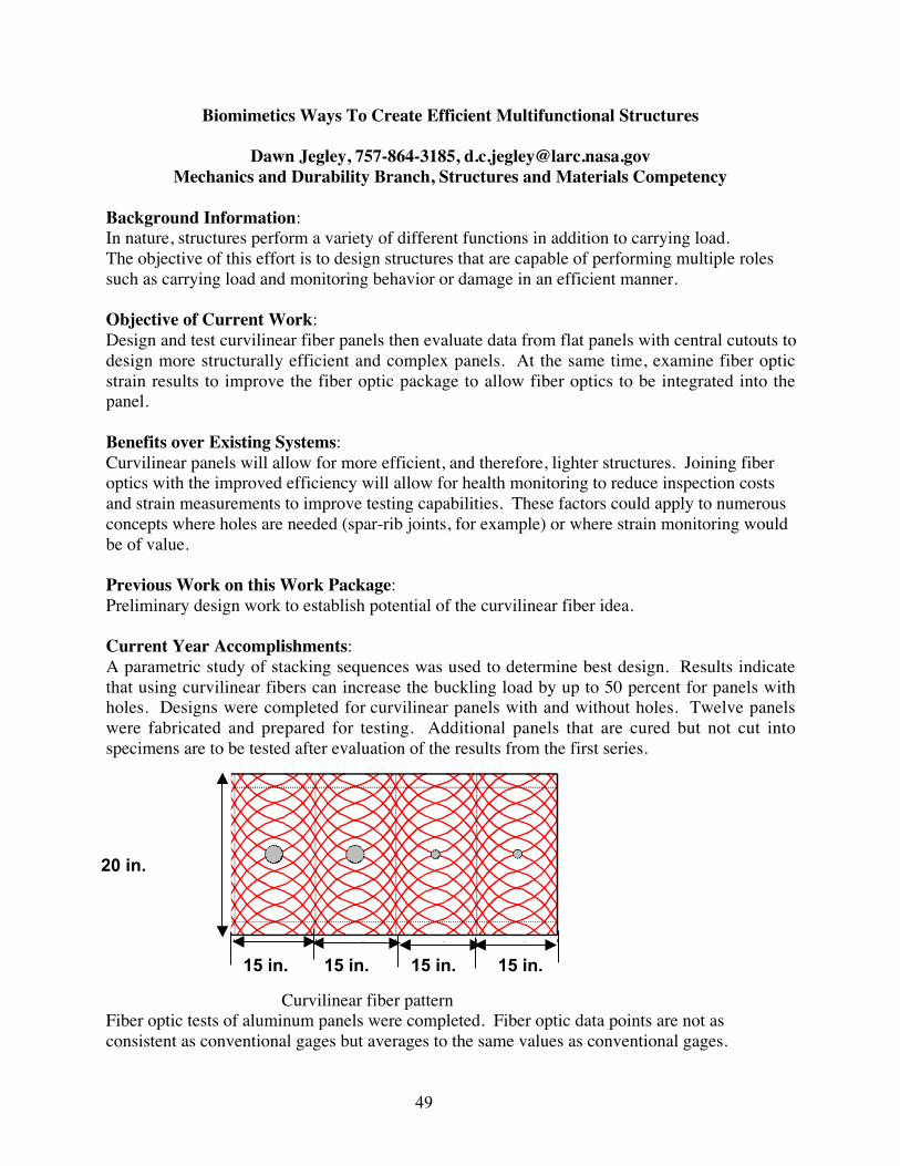
49
Biomimetics Ways To Create Efficient Multifunctional Structures
Dawn Jegley, 757-864-3185, [email protected] and Durability Branch, Structures and Materials Competency
Background Information:In nature, structures perform a variety of different functions in addition to carrying load.The objective of this effort is to design structures that are capable of performing multiple rolessuch as carrying load and monitoring behavior or damage in an efficient manner.
Objective of Current Work:Design and test curvilinear fiber panels then evaluate data from flat panels with central cutouts todesign more structurally efficient and complex panels. At the same time, examine fiber opticstrain results to improve the fiber optic package to allow fiber optics to be integrated into thepanel.
Benefits over Existing Systems:Curvilinear panels will allow for more efficient, and therefore, lighter structures. Joining fiberoptics with the improved efficiency will allow for health monitoring to reduce inspection costsand strain measurements to improve testing capabilities. These factors could apply to numerousconcepts where holes are needed (spar-rib joints, for example) or where strain monitoring wouldbe of value.
Previous Work on this Work Package:Preliminary design work to establish potential of the curvilinear fiber idea.
Current Year Accomplishments:A parametric study of stacking sequences was used to determine best design. Results indicatethat using curvilinear fibers can increase the buckling load by up to 50 percent for panels withholes. Designs were completed for curvilinear panels with and without holes. Twelve panelswere fabricated and prepared for testing. Additional panels that are cured but not cut intospecimens are to be tested after evaluation of the results from the first series.
��″� ��″� ��″���″� ��″�
����� ��″
� ″�
��″
Curvilinear fiber patternFiber optic tests of aluminum panels were completed. Fiber optic data points are not asconsistent as conventional gages but averages to the same values as conventional gages.
15 in. 15 in. 15 in. 15 in.
20 in.

50
y = 6.1515E+06x
R2 = 9.9718E-01
0
0
0
0
0
0
0
0.00
00E
+00
2.00
00E
-04
4.00
00E
-04
6.00
00E
-04
8.00
00E
-04
1.00
00E
-03
1.20
00E
-03
1.40
00E
-03
1.60
00E
-03
1.80
00E
-03
Lo
ad (
lbs)
FO 1-A-2 (2)
RG - ModComp
Linear (FO 1-A-2 (2))
κ=0.775
Strains determined by fiber optics and by conventional gages.
Lessons Learned:Shifting the tows of material when graphite panels are constructed reduces the tendency to warpduring and after curing. Quality control must be improved on the fiber optic wires.
Future Work:Curvilinear fiber panel testing in compression is to be completed in FY 2002. Integration ofcurvilinear fibers and fiber optics will continue. Analysis of the wire itself (coatings, adhesive,etc.) will be initiated.
External Partners and Their Accomplishments:Adoptech Inc., designed the curvilinear panels and Cincinnati Machine fabricated them.
Load
Strain

51
Adaptive Wing Structural Concepts
Tom Jordan, 757-874-4713, [email protected] Systems Branch, Aerodynamics, Aerothermodynamics and Acoustics Competency
Background Information:Birds, bats, and marine creatures have demonstrated the ability of a single system to achievemultiple tasks through the ability to drastically change shape. Although adaptive wing structuresand multipoint design have been demonstrated in aircraft through the use of high lift systems,aeroelastic tailoring, variable sweep, and other methods; it is believed that new methods for wingshape change that mimic biological structures can be achieved using recent advances inmaterials, smart actuators, electronics, and control systems.
Objective of Current Work:The objectives of the current work include:1. Develop novel structural concepts for wings and other lifting surfaces that provide multipoint
efficiency without traditional hinged surfaces.2. Investigate emerging technologies in smart actuators, sensors, MEMS, and associated
electronics for use on new wings with non-traditional control surfaces.3. Investigate and develop flexible and segmented surfaces to act as wing coverings that require
significant dimensional change.4. Investigate fabrication techniques for all the above electrical and mechanical hardware.5. Coordinate with other groups within LaRC to target aerodynamically high-payoff
configurations for a given missions.
Benefits over Existing Systems:Previous work in this area has been focused on relatively small changes to the leading andtrailing edges of wing surfaces. This work will develop aerodynamic surfaces with largestructural changes and incorporate the enabling hardware and electronics.
Previous Work on this Work Package:The Adaptive Wing Concepts work package started in 2001.
Current Year Accomplishments:A team within the Model Systems Branch was formed. The team generated 14 concepts thatcould provide desired shape changes. These concepts were ranked and three concepts weredesigned from the ranked concept list; two of the concepts were fabricated. The Fishbone Wingwas designed by MSB personnel and fabricated in-house. A PC-based system was developedwhich controls the shape of the wing. The other demonstrator was designed and fabricated byAdvanced Technologies Inc (ATI), and delivered to MSB personnel in September of 2001.Enabling technologies such as flexible or segmented skins were identified and requiredevelopment for future progress.
Lessons Learned:1. Elastic, pliable, and segmented skins are key elements for many conceptual designs.2. Currently available smart actuators are still behind conventional actuation systems as far as
stroke, force, frequency response, and operational lifetime. However, there is much researchin this area, which will likely provide new smart actuators that are ideal for some

52
applications. Wind tunnel models and demonstrators that utilize smart materials and smartactuators require extensive amounts of electrical hardware for support. Miniaturization ofelectrical hardware will be required for use on flight vehicles.
3. Actuation systems must work in concert with the wing structure to achieve the desiredshapes. This requires the development of concepts where structural stiffness is dynamicallycontrolled. The structure should only be stiff enough to resist flutter for the desired flightconditions.
4. Wind tunnel testing will require mechanical hardware, actuators, instrumentation, and skinswith much greater complexity than those used on current wind tunnel tests. More in-depth,structural/dynamic analysis will be required to meet safety standards for testing of morphingwind tunnel models. New methods of measurement for quantifying surface deflection ofaerodynamic surfaces need to be developed.
Future Work:Future work will be to:1. Continue all current work described above.2. Investigate and develop methods to obtain 3-D surface contour for flexible structures
undergoing wind tunnel testing.3. Integrate structural design and sensor/actuator technology for wind tunnel and R/C models.4. Perform kinematic analysis, structural analysis, and aerodynamic payoff for all existing and
subsequent concepts. MSB and other groups will perform these analyzes.
Formal and Informal Documentation Available:Contract report for ATI demonstrator, model # RBL-01-0183.Contract report for DEI demonstrator, model # RBL-01-0184.
External Partners and Their Accomplishments:Advanced Technologies Inc., designed and fabricated a model that demonstrates large changes inwing tip deflection. Dynamic Engineering Inc., (DEI) designed a demonstrator model thatincorporates Shape Memory Alloy (SMA) actuators to achieve structural morphing objectives.This model was designed but not fabricated.
FFiisshhbboonnee DDeemmoonnsstt rraa ttoorr
AATTII DDeemmoonnsstt rraa ttoorr
AAddaapptt iivvee AA ee rr oo ee ll aa ss tt ii cc
DDeemmoonnsstt rraa ttoorr ((DDEEII ))

53
High-Rate, Morphable, Hingeless Control Surface Demonstrated in the TDT
Jennifer Pinkerton Florance, 757-864-1230, [email protected] Branch, Structures and Materials Competency
Background Information:Typically, aircraft wings are designed to be most efficient at a single flight condition but sufferperformance penalties at other flight conditions. Historically, these penalties have been reducedthrough the judicious deflection of “conventional” leading- and trailing-edge hinged controlsurfaces. Since the 1980’s, many researchers have investigated the use of fully-integratedadaptive material actuator systems (so called “smart technologies”) for performance-enhancingshape control. These devices are promising because they offer a significant advantage over theirconventional counterparts: no flow-disturbing hingelines. The DARPA/AFRL/NASA/NorthropGrumman Smart Wing program was one such effort addressing the development anddemonstration of smart technologies.
Objective of Current Work:The overall objective of the Smart Wing program was to develop smart technologies anddemonstrate novel actuation systems to improve the aerodynamic and aeroelastic performance ofmilitary aircraft. The FY 2001 wind-tunnel test in the Transonic Dynamics Tunnel (TDT)focused on demonstrating realistic actuation rates of a hingeless, smoothly contoured, “smart”trailing-edge control surface while maintaining or improving the aerodynamic performancebenefits demonstrated during previous Smart Wing TDT entries.
Benefits over Existing Systems:The results of the Smart Wing program have laid the ground work for developing smart controleffectors that can provide an alternative and potentially more effective means of achievingaerodynamic and aeroelastic control while improving the low observable characteristics of futureair and space vehicles, particularly if considered early in the design cycle. Issues related topower supplies, cost, system reliability, and overall system integration must still be overcome,but the demonstration of high-actuation-rate, hingeless, smoothly contoured control surfaces withboth chordwise and spanwise shape variability are a significant milestone in the developmentand application of smart technologies.
Previous Work on this Work Package:The Smart Wing program began in 1995 and was comprised of two phases. In Phase 1, whichended in February 1999, two 16 percent geometric-scale semi-span models of an advancedmilitary aircraft wing, one with hingeless nickel-titanium (NiTi) shape-memory-alloy (SMA)trailing-edge smart control surfaces and a central torque tube (to provide wing twist) and theother with conventional trailing-edge control surfaces, were tested twice in the TDT. During thetests, a maximum of 5 degrees of wing twist was achieved using the SMA torque tube concept,resulting in an approximate 15 percent increase in rolling moment and 11 percent increase in liftrelative to the untwisted conventional wing. The SMA control surfaces were deployed up to 10degrees, with the hingeless ones providing (1) an approximate 10 percent improvement in liftand rolling moment for independent control surface actuation (flap and aileron alone,respectively) and (2) a 15-17 percent improvement in lift and rolling moment for combined

54
deployment. Phase 2 of the program began in January 1997 and utilized a sting-mounted, full-span, 30 percent geometric-scale, flexible model based on the Northrop Grumman UnmannedCombat Air Vehicle (UCAV) concept with smart, hingeless control surfaces on the starboardwing and conventional control surfaces on the port wing. Deflections of –10 degrees to 8degrees for a smart trailing edge and –4.5 degrees for a smart leading edge were demonstrated.The effectiveness of the leading edge to maintain roll control as the trailing-edge “aileron”became less effective with increasing dynamic pressure was also demonstrated.
Current Year Accomplishments:The second Phase 2 test in the TDT (which began inApril 2001) focused on control surface deflection rate.To achieve the desired higher deflection rate, NorthropGrumman replaced the Phase 2 Test 1 SMA-actuatedtrailing-edge control surface, which had a maximumpotential actuation rate of less than 3 Hz, with analternative smart technology concept: a control surfaceutilizing eccentuator arms driven by piezoelectricultrasonic motors. The result was a fast (>70 deg/sec),morphable, hingeless control surface that maintained orimproved the aerodynamic performance benefitsdemonstrated during the previous three tests. Uniform conventional control surface deflectionsof up to ±20 degrees, uniform smart control surface deflections of up to +20/-15 degrees, and 71different smart control surface spanwise variation shapes were tested at Mach numbers up to 0.8and dynamic pressures up to 150 psf. To the best of the test team’s knowledge, the second Phase2 test was also the first demonstration of such a control surface under realistic loads, sized suchthat it could be used on an operational UAV. During the test, three LaRC-developedinstrumentation systems were used: two model deformation measurement systems to measuredeflections of the smart trailing-edge control surface (Videogrammetric Model Deformation(VMD) and Projection Moiré Interferometry (PMI)) and a sting whip correction package toprovide model angle of attack. All three systems had been utilized during previous Smart Wingentries but exercised new capabilities for the first time during this entry. An additional modeldeformation system (Optotrak) was also used for the second time during the program.
Lessons Learned:1. Wing twist due to aerodynamic loading and smart control surface segment twisting during
non-uniform deflections both influenced the external model deformation measurements.This is because the external measurement systems observed the wing motion from a fixedreference frame, resulting in measurements that encapsulated the total motion of the wing.
2. The VMD retro-reflective dots did not adhere well to the smart control surface silicon/RTVskin material.
3. Even after all non-essential lights were extinguished, the Optotrak system experiencedinterference from the tunnel lights during both Phase 2 entries.
Future Work: The Smart Wing program officially ended on September 30, 2001.
Phase 2. Test 2 Model in the LangleyTransonic Dynamics Tunnel

55
Formal and Informal Documentation Available:1. Kudva, J. N.; et al: Adaptive Smart Wing Design for Military Aircraft: Requirements,
Concepts, and Payoffs. SPIE North American Conference on Smart Structures andMaterials, Vol. 2447, Paper No. 2447-04, 1995.
2. Kudva, Jayanth N.; Martin, Christopher A.; Scherer, Lewis B.; Jardine, A. Peter; McGowan,Anna-Maria Rivas; Lake, Renee C.; Sendeckyj, George P.; Sanders, Brian P.: Overview ofthe DARPA/AFRL/NASA Smart Wing Program. SPIE Conference on Smart Structures andMaterials, Industrial and Commercial Applications of Smart Structures Technologies, Vol.3674, Paper No. 3674-26, pp. 230-236, 1999.
3. Kudva, J. N.; Sanders, B.; Pinkerton-Florance, J.; Garcia, E.: Overview of theDARPA/AFRL/NASA Smart Wing Phase 2 Program. SPIE Conference on Smart Structuresand Materials, Industrial and Commercial Applications of Smart Structures Technologies,Vol. 4332, Paper No. 4332-48, 2001.
4. Kudva, J. N.; Sanders, B.; Garcia, E.: Overview of the DARPA/AFRL/NASA Smart WingPhase 2 Program. SPIE’s 9th Annual Symposium on Smart Structures and Materials, Vol.4698, Paper No. 4698-04, 2002. Expected publication date, fall 2002.
5. Martin, C. A.; et al: Design, Fabrication and Testing of the Scaled Wind Tunnel Model forthe Smart Wing Phase 2 Program. SPIE’s 9th Annual Symposium on Smart Structures andMaterials, Vol. 4698, Paper No. 4698-05, 2002. Expected publication date, fall 2002.
6. Wang, D. P.; et al: Development, Control, and Test Results of High Rate, Hingeless TrailingEdge Control Surface for the Smart Wing Phase 2 Wind Tunnel Model. SPIE’s 9th AnnualSymposium on Smart Structures and Materials, Vol. 4698, Paper No. 4698-06, 2002.Expected publication date, fall 2002.
7. Scherer, L. B.; et al: DARPA / AFRL Smart Wing Phase 2 Wind Tunnel Test Results. SPIE’s9th Annual Symposium on Smart Structures and Materials, Vol. 4698, Paper No. 4698-07,2002. Expected publication date, fall 2002.
8. Smart Materials and Structures – Smart Wing Phase 1, Volumes I, II, III, and IV. ContractFinal Report, AFRL-ML-WP-TR-1999-4162, Contract Number F33615-95-C-3202,December 1998.
9. Smart Materials and Structures – Smart Wing Phase 2. Contract Final Report, ContractNumber F33615-97-C-3213. Expected Publication, Fall 2002.
External Partners and Their Accomplishments: The Smart Wing program was led by theNorthrop Grumman Corporation under a Defense Advanced Research Projects Agency(DARPA)-funded contract, which was monitored by the Air Force Research Laboratories(AFRL), and included partnering with NASA Langley Research Center for technical guidance,wind-tunnel testing, and CFD analysis.

56
SAMPSON - Smart Aircraft and Marine Projects System Demonstration
Jeffrey D. Flamm, 757-864-5955, [email protected] Aerodynamics Branch, Aerodynamics, Aerothermodynamics and Acoustics
Competency
Background Information:The SAMPSON program mission was to use Smart Materials based Marine and Aircraftdemonstrations as development tools to expand and demonstrate the ability of Smart StructuresTechnology to provide significant expansion of vehicle operating envelopes to enable newmissions.
Objective of Current Work:Demonstrate a full-scale fighter aircraft inlet with highly integrated smart structures capable ofproviding more than a 20 percent increase in mission radius relative to conventional fixed inletdesign.
Benefits over Existing Systems:A variable geometry inlet provides up to 20 percent increase in mission radius (relative to fixedinlet baseline design) or a corresponding increase in fuel efficiency. It also enables strike aircraftoptimized for subsonic interdiction mission to also perform supersonic intercept mission.
Previous Work on This Work Package:1. First wind tunnel test completed May 5, 2000. A full-scale F-15 inlet (modified flight
hardware) was used as the test article.2. Demonstrated a shape memory alloy (SMA) wire-based actuator to vary an inlet fore-cowl
and ramp positions under simulated full-scale aerodynamic operating conditions (M = .3 to.70)
3. Verified the predicted angle of attack and sideslip for the inlet which resulted in minimumsupport system loads
4. Obtained pressure distributions on the lower inlet lip to support future work on lip-bluntingconcept.
Current Year Accomplishments:1. Completed second wind tunnel entry, February 2001.2. Demonstrated an SMA wire-based actuator to vary an inlet fore-cowl and ramp positions
under simulated full-scale aerodynamic operating conditions (M = .3 to .80) for inlet capturearea control.
3. Demonstrated nacelle lip rotation (± 20 deg) using integrated SMA rod actuators withincompliant structure under simulated full-scale aerodynamic operating conditions (M = .3 to.80) for inlet capture area control
4. Demonstrated the use of integrated SMA rod actuators within compliant structure foradaptive wall shaping for compression ramp generation in lab (generated 2” bump).
5. Demonstrated the use of piezo actuators and superelastic SMA skin for lip radius change forbluntness control in lab (radius varied from r = 0.125” to r= 1.0”).
6. Analysis of Supersonic Covert Penetrator in Supersonic Covert Penetration Mission showsapproximate 5 percent range increase with variable lip bluntness.

57
7. Analysis of lightweight strike fighter in deck Launched Intercept Mission shows approximate20 percent range increase for combined variable capture area and compression ramp.
Lessons Learned:The SAMPSON program conclusively demonstrated that smart materials can be integrated intoan aircraft structure and used to provide large forces and displacements to optimize the aircraftshape at realistic (full-scale) aerodynamic conditions. An SMA actuator was successfullyintegrated into a full-scale F-15 inlet to replace the conventional hydraulic actuator system torotate the inlet fore-cow and vary inlet capture area. This actuator was capable of providing upto 20,000 lbs of force and a displacement of 6 inches. The program also demonstrated that SMArod actuators could be integrated into compliant structural configurations. The leading edge ofthe inlet was deflected up to 20 degrees at flow conditions up to Mach 0.8 using SMA Rodsembedded in flexskin. Adaptive wall shaping using SMA Rod/flexskin technology was alsosuccessfully integrated into the F-15 inlet and demonstrated without flow. A mishap resulting inthe loss of the model prevented testing the adaptive wall shaping technology under aerodynamicload. The use of piezo actuators and superelastic SMA skin was demonstrated to achieve avariable leading edge lip radius of 0.125 to 1 inch in a lab environment. Continued work isneeded to develop a high-temperature SMA to open more areas on aircraft to the use of SMA.
Future Work: Program finished.
Formal and Informal Documentation Available:1. Boeing is preparing a CD-Rom containing all program documentation.2. Dunne, J. P., Hopkins, M. A., Erwin W. Baumann, Pitt, D. M., and White, E. V.: Overview
of the SAMPSON Smart Inlet. 6th Annual International Symposium on Smart Structures andMaterials Conference, March 1-5, 1999, Newport Beach, California.
3. Hopkins, M. A., Dunne, J. P., Baumann E. W., Pitt, D. M., and White, E. V: AdaptiveFighter Engine Inlet. AIAA paper 99-1512, 40th AIAA Structures, Structural Dynamics, andMaterials Conference, April 12-15, 1999, St. Louis, Missouri.
4. Dunne, J. P., Pitt, D. M., White E. V. and Garcia, E.: Ground Demonstration of the SmartInlet. AIAA Paper 2000-1630, 41st Structures, Structural Dynamics, and MaterialsConference, April 3-6, 2000, Atlanta, Georgia.
5. Pitt, D. M.: SAMPSON Smart Inlet First Entry – Test Report. Boeing report, July 24, 2000.6. Pitt, D. M., Dunne, J. P., White, E. V., Garcia, E.: Wind Tunnel Demonstration of the
SAMPSON Smart Inlet. 8th Annual International Symposium on Smart Structures andMaterials Conference, March 4-8, 2001, Newport Beach, California.
7. Pitt, D. M., Dunne, J. P., White, E. V., Garcia, E.: SAMPSON Smart Inlet SMA PoweredAdaptive Lip Design and Static Test. AIAA-01-1359, 42nd Structures, Structural Dynamics,and Materials Conference, April 16-20, 2001, Seattle Washington.
External Partners and Their Accomplishments:The SAMPSON program was a joint program between DARPA (Sponsor), NASA (Aircraftprogram technical monitor, wind tunnel testing), Institute for Defense Analysis (IDA, DARPAliaison), Office of Naval Research (ONR, Marine program technical monitor), Boeing (Primecontractor), Electric Boat (marine program management), and Penn-State (core- technology,piezo actuator design/fab, aircraft lip-blunting concept design/fab).

58
SAMPSON F-15 Installed in NASA LaRC 16 Foot Tunnel
0
1
2
3
4
5
6
7
8
9
35 40 45 50 55 60 65 70 75 80
Time - Seconds
Cow
l Ang
le -
Degr
ees
Cowl Down
Cowl Up
Cowl Up Rotation Angle vs. Time at M = 0.8
-1500
-1000
-500
0
500
1000
1500
2000
2500
3000
3500
4000
35 40 45 50 55 60 65 70 75 80
Time - Seconds
Forc
e (P
ound
s)
Actuated Wires
Antagonistic Straining WiresCowl Load
Cowl Up Rotation Loads vs. Time at M = 0.8

59
Langley Adaptive Aeroelastic Demonstrator
Robert Scott, 757-864-2838, [email protected] Branch, Structures and Materials Competency
Background Information:Aeroservoelastic research using smart actuators or adaptive materials has been performed inseveral wind tunnel test programs. These programs include Piezoelectric Aeroelastic ResponseTailoring Investigation (PARTI), Actively Controlled Response Of Buffet Affected Tails(ACROBAT), Smart Wing, Active Twist Rotor, and Active Materials Rotor programs.Additionally, there have been a variety of small wind tunnel investigations on very simplemodels, as well as, numerous computational studies. These research programs have providedsome valuable insights into the use of smart actuators/materials for aeroservoelastic applicationsyet they have had some limitations. These limitations include the use of simple or unrealisticstructures, retrofit applications, limited ASE tailoring performed or demonstrated, rigid modelswith no ASE objectives, flutter suppression marginally successful, or the program was notrelevant to fixed wing configurations.
Objective of Current Work:The objective of this work package is to explore ways to use smart structures concepts to exploitstatic and dynamic aeroelastic deformations to improve aircraft performance. This objective willbe pursued by three main avenues of research:1. Development of aeroelastic performance objectives and active material performance
requirements.2. Development of tools and methods for performing aeroservoelastic tailoring with active
materials.3. Evaluating technologies by performing aeroservoelastic analyses and wind tunnel testing.
Benefits over Existing Systems:It is still unclear how or if smart structures can be used to improve the aeroelastic performance ofaircraft; design and analysis tools that can be used for these structures are not mature; and hardengineering data for aeroelastic applications of these technologies is limited. This project willmake contributions in all of these areas.
Current Year Accomplishments:FY 2001 ApproachThe work performed in FY 2001 was focused primarily on utilizing the existing AeroservoelasticSemispan Model (ASM) as the baseline configuration for a wind tunnel testbed. New wingswere to be designed to demonstrate and evaluate devices for use in controlling static anddynamic aeroelastic response to reduce loads and structural weight and increase aerodynamicperformance. The first wing was to incorporate embedded Macro Fiber Composite (MFC)(piezoelectric) actuators for active aeroelastic control. In order to design this type of activestructure, design tools and methods needed to be developed. Simple beam and plate finiteelement models (FEM) were used to develop techniques for optimizing discrete actuatorlocations and composite skin thicknesses and orientations. After satisfactory evaluation of thesetools on simple beam/plate models, they will be applied to a simplified FEM of the ASM wing.Additionally, simple beam and plate coupons were to be fabricated and tested to verify windtunnel model fabrication and analysis methods.

60
FY 2001 AccomplishmentsDesign/optimization tools incorporating iSIGHT and NASA Structural Analysis (NASTRAN)codes to perform simultaneous skin tailoring and actuator placement/orientation studies wereimplemented on beam/plate coupon finite element models. The baseline ASM wing FEM hasbeen simplified in preparation for design/optimization studies. Several active and passivecoupons have been designed and fabricated, Transonic Dynamics Tunnel (TDT) laboratorieshave been set up for projection moiré interferometry (PMI) testing, and PMI deflectionmeasurements have been made for externally loaded beam/plate coupons and for MFC actuatedbeam/plate coupons. Ground vibration testing (GVT) and stiffness testing were performed onthe baseline ASM wing. This data was compared with the wing FEM indicating generallysatisfactory correlation. Several previously uncompleted components of the ASM testbed havebeen fabricated, and the ASM has been mothballed for future use.
Lessons Learned:Potential fabrication methods appropriate for a wind tunnel model wing incorporating MFCactuators have been validated: MFC actuators co-cured with fiberglass prepreg skins over ahoneycomb core. Mass and stiffness differences between the baseline ASM wing FEM andexperimental stiffness/vibration data indicate some potential modeling and fabricationshortcomings that will need to be addressed in future wings. Finite element analysis ofbeam/plate coupon models that incorporate MFC actuators using nominal published propertiesover predicted deflections achieved experimentally. Optimization of discrete actuator locationsusing the simulated annealing approach available within iSIGHT was found to becomputationally expensive for even small problems. In spite of these limitations, the approachdid succeed in finding optimal actuator locations that were slightly better (2 percent) than theexpected result.
Future Work:1. A literature search will be performed to determine what the state of the art is and avoid
duplication of effort, outside experts in the field will be consulted and possibly hired toperform evaluations and analyses, and aeroservoelastic tailoring requirements studies will beperformed.
2. The in-house effort to develop an aeroservoelastic tailoring capability using the iSIGHT andNASTRAN codes will be continued. This effort will initially be exercised on simplebeam/plate models with the ultimate objective being the demonstration of aeroservoelastictailoring on a wing finite element model having MFC actuators. This effort will besupplemented with various small experimental demonstrations and correlation studies.
3. Existing wind tunnel and finite element models including the ASM will be used forevaluations. Additionally, new models will be designed and built or acquired, as necessary,to evaluate various technologies. The first wind tunnel test to be performed as part of theLAAD project will be of the Stingray Unmanned Air Vehicle (UAV). The goal of thisactivity will be to obtain performance data for active flow control devices.
External Partners and Their Accomplishments:The Aerospace, Transportation, and Advanced Systems Laboratory of the Georgia TechResearch Institute is collaborating with LaRC to perform of a wind-tunnel test of the StingrayUAV to evaluate new wing skin panels with imbedded synthetic jets for virtual shape change athigh angles of attack. To date, the Stingray UAV vehicle has been flight tested, and the syntheticjet wing skins are being designed.

61
Elastic Tailoring and Active Control of Wing Structures
David M. McGowan, 757-864-4916, [email protected] and Durability Branch, Structures and Materials Competency
Background Information:This research can provide the understanding necessary to allow for more aggressive designs offuture aerospace vehicles by coupling elastic tailoring principles with smart structurestechnology. An understanding of the effect of embedded actuators and sensors will also advancethis technology. If successful, more aggressive designs can translate into lighter-weight, morefuel-efficient structures.
Objective of Current Work:Develop reduced weight, adaptive/reconfigurable wing structures with enhanced structuralintegrity and that synergistically integrate elastic tailoring, smart component technologies, andsensing systems.
Benefits over Existing Systems:Combines passive control (elastic tailoring) technology with active control (smart structures)technology.
Previous Work on this Work Package: New Work Package for FY 2001.
Current Year Accomplishments:Developed analytical models to predict the response of composite laminates with embeddedpiezoelectric actuators with delaminations present on one surface. Identified E-beam curing as apotential manufacturing method for producing unsymmetric laminates. Investigated themanufacturability of unsymmetric laminates that can be used in an elastic tailoring applicationby fabricating several unsymmetric laminates with different elastic coupling characteristics.Designed an unsymmetrically laminated composite wing box representative of the outer wingbox of an F-18. Boeing, Seattle has fabricated the cover panels for this wing box. Conductedmaterial property characterization of E-beam cured materials, and began investigating thermalpost curing methods for E-beam cured laminates. Developed analysis tools for determiningcuring stresses for unsymmetric laminates produced by an autoclave curing process.Investigated manufacturing techniques for embedding piezoelectric actuators through thethickness of a composite laminate.
Lessons Learned:Analytical results indicate that the presence of a delamination over one surface of a LaRCmacro-fiber composite (MFC) actuator embedded into a composite laminate reduced theeffectiveness of the actuator by 33 percent (based upon the maximum axial displacementoccurring in the laminate). The presence of the delamination also results in unwanted out-of-plane deformation. These effects are shown in figure 1 below.

62
(a) No delamination, umax = 1.46E-3 in. (b) Delamination present, umax = 0.976E-3 in.
(c) No delamination, wmax = 4.07E-10 in. (d) Delamination present, umax = 1.49E-4 in.
Figure 1. Composite laminate with embedded LaRC MFC actuator.
Fabrication demonstrations indicated that E-beam curing holds a lot of potential formanufacturing anisotropic (tailored) laminates. However, E-beam cured unsymmetric laminateshave exhibited a tendency to recover some warpage primarily due to incomplete initial curing ofthe polymer followed by progression of the cure at room temperature.
Future Work:Develop actuation devices and systems for configuration changes at the global and local levels.Address issues related to the integrity of composite structures with embedded morphing devicesusing autoclave and non-autoclave processes (e.g., SMA hybrid composites and embedded fiber-optic sensors). Develop analysis tools to investigate morphed structural response (includingmodeling of morphing devices such as SMA hybrid composites). Develop, implement, andvalidate concepts for morphing using actuation devices and systems.
External Partners and Their Accomplishments:Virginia Tech: Residual thermal stress analysis of autoclave-cured composite laminates.The Boeing Company, Seattle, Washington: E-beam curing of unsymmetric laminates andF-18 wing box covers.

63
Multifunctional Adaptive Structures
Travis L. Turner, 757-864-3598, [email protected] Acoustics Branch, Aerodynamics, Aerothermodynamics and Acoustics
Competency
Background Information:Novel material systems and structures are needed for multi-mission morphing vehicles.Conventional structures are limited to single point designs and adaptability incurs large designpenalties. Morphing concepts necessitate advanced materials and structures fabricationtechnology, characterization of the material systems and models to predict the behavior of suchmaterials and structures.
Objective of Current Work:Refine shape memory alloy (SMA) processing and characterization technology. Demonstratefabrication and performance of a practical structure with embedded SMA. Validate the effectivecoefficient of thermal expansion (ECTE) constitutive model for SMAs and SMA hybridcomposite (SMAHC) structures and facilitate implementation of the model in a commercialfinite element (FE) environment.
Benefits over Existing Systems:The LaRC SMA characterization activity is not only supplying property data for modeldevelopment/validation and applications, but also uncovering unique behaviors not reported inthe literature. LaRC-developed SMAHC fabrication technology is amenable to automation andis commercially viable. The LaRC-developed ECTE constitutive model for SMAs/SMAHCs isthe only known model that is implicitly amenable to commercial implementation.
Previous Work on This Work Package:A thermoelastic constitutive model (ECTE) was developed for analysis of SMAs/SMAHCs.Methods for SMA characterization and SMAHC fabrication were developed. SMAHC beamspecimens were fabricated and the material system was characterized. The ECTE model wasqualitatively validated against experimental results.
Current Year Accomplishments:Further prediction-measurement correlation studies of the SMAHC beam specimens led toquantitative validation of the ECTE model and corresponding FE implementation. A contractwas established with MSC.Software Corporation to implement the ECTE constitutive modelwithin the standard solution procedures of MSC.NASTRAN, thereby becoming a fully supportedmaterial system option. A side benefit of this development is that MSC.Software is committedto implementation of temperature dependent material properties for their full element library. Apanel specimen with bi-directional SMA reinforcement was fabricated and thermal-structural-acoustic test hardware was designed and fabricated, figure 1. Random vibration and acoustictransmission tests are currently under preparation. A data acquisition and control system hasbeen developed to automate the measurement of SMA recovery force versus temperature andthermal cycle, figure 2. This capability, in combination with infrared thermography, will providean enormous improvement in test accuracy, repeatability, and data rate. The control system istest stand independent and will also form a basis for automation of other related tasks, such asSMA actuator training. A complimentary microstructural analysis capability is under

64
development to help discern the relationships between thermomechanical history, crystallinestructure/phase content and thermomechanical properties. A concept for automation of theprestrain operation on SMA actuators has been developed and system component selection isunderway. This technology will not only vastly reduce the time/effort to process SMA actuatorsand fabricate SMAHC specimens, but will also provide an automated SMA actuatorpreprocessing capability that can be integrated into a robotic tape laying system for fullyautomated SMAHC fabrication.
Figure 2. SMAHC panel thermal-structural- Figure 3. SMA recovery force testacoustic test assembly. automation system
Lessons Learned:ECTE model may be difficult to use for shape control prediction. SMAcharacterization/processing is very tedious and labor intensive, necessitating automation. SMAcharacteristics are very complex, which impacts implementation and modeling.
Future Work:Develop models for shape control and implement in commercial FE environment. Expand SMAcharacterization for shape control modeling and applications. Fabricate benchmark shape controlspecimens for demonstration and model validation. Investigate active/passive flexible skintechnology. Investigate embedded fiber optic strain measurement for closed-loop shape control.
Formal and Informal Documentation Available:1. Turner, Travis L. A New Thermoelastic Model for Analysis of Shape Memory Alloy Hybrid
Composites. Journal Intell. Mat.. Sys. & Struct. 11(5) 382-394, May 2000.2. Turner, Travis L. Thermomechanical Response of Shape Memory Alloy Hybrid Composites.
NASA TM-2001-210656, January 2001.3. Turner, Travis L. Experimental Validation of a Thermoelastic Model for SMA Hybrid
Composites. SPIE's 8th Annual Internat'l Symposium on Smart Structures and Materials,March 4-8, 2001, Newport Beach, California, SPIE 4326-24.
4. Turner*, Travis L.; Lach, Cynthia L.; Cano, Roberto J. Fabrication and Characterization ofSMA Hybrid Composites. SPIE's 8th Annual Internat'l Symposium on Smart Structures andMaterials, March 4-8, 2001, Newport Beach, California, SPIE 4333-60.
External Partners and Their Accomplishments:MSC.Software activity detailed above.

65
Synergistic Tailored Design of Metals and Structures
Kim S. Bey, 757-864-1351, [email protected] and Thermal Structures Branch, Structures and Materials Competency
Objective of Current Work:Investigate functionally graded metallic foams as an alternative thermal protection systemconcept for space transportation vehicles.
Benefits over Existing Systems:An integrated thermal-structural concept in which the load bearing structure has insulatingcapability and has potential for significant weight savings over current thermal protectionsystems (TPS). Current TPS do not have a structural function so they are parasitic from astructural viewpoint. Current TPS include coated ceramic tiles or blankets of fibrous insulationaffixed to the vehicle surface and metallic panels in which fibrous insulation is encapsulated infoil and placed between an outer metal surface and the vehicle structure. A multifunctional TPSconcept is based on metallic panels that are continuously graded in composition and porosity.
Current Year Accomplishments:Heat is transferred through metallic foam by conduction through the metallic “skeleton” and byconduction and radiation through the gas in the voids. Simplified models for the effectivethermal conductivity of open- and closed-cell metallic foams were developed. Results fromthese models indicated that sufficiently porous (~ 95 percent) closed-cell foams fabricated fromhollow Titanium spheres have an insulating capability comparable to ceramic blankets and tiles.
Foams made of Titanium- and Nickel-based alloys are extremely vulnerable to oxidation andrequire some type of coating. Solgel processes can be used to apply a coating to protect againstoxidation and to form Aerogels (extremely lightweight insulating materials) that can be used as afiller to eliminate conduction in the voids of the foam. A process was developed to prepare afoam-aerogel composite by impregnating or coating metallic foams with Silica aerogel.Microstructure characterization using SEM microscopy indicated a stable aerogel matrix withadhesion to the metal substrate. Representative micrographs of as delivered open-cell Aluminumand Nickel foam and the aerogel-impregnated foams are shown in figure 1.(POC: Jeffrey Jordan, x45067, AMDB, AAAC)
Aluminum Nickel As delivered
x20 x100 x250 x500 x1000 Aerogel impregnated
Figure 1. Micrographs of open-cell foams before and after impregnation with Aerogel.

66
A literature survey of Computational Materials Science and Engineering for metals wascompleted. A white paper presenting an overview of the theory of metallic materials at variouslength scales (nano to meso) and related computational techniques is 25 percent complete.
External Partners and Their Accomplishments:Fraunhofer Inc., developed processing methods for fabricating hollow sphere foams of TitaniumAluminides. Several processes were investigated and samples were delivered with the desired 95percent porosity. Unfortunately, the processing left the material with significant Oxygen andCarbon impurities, and the samples were extremely brittle.
A grant was initiated with the University of Florida to develop optimization methodology forfunctionally graded materials. Two open-cell foam panel designs were optimized byfunctionally grading the porosity of the foam through the panel thickness. Porosity, and likewisedensity, of metallic foam is controlled by varying the cell (void) size and the thickness of themetal skeleton. For one panel design, the density was graded to optimize insulating capacity(minimize the heat transfer). For the other panel design, the density was graded to minimize themass. Results are preliminary since transients were neglected.
Lessons Learned:Functionally graded porous materials will undoubtedly play a major role in weight-savingmultifunctional concepts for space transportation. However, metallic foams lack the structuralefficiency that is necessary to make them competitively viable candidates.
Future Work:The focus of this task will shift to processing of shape memory alloys. Optimization offunctionally graded materials will continue under the Integrated Thermal-Structural Conceptstask of 3rd Generation Reusable Launch Vehicle (RLV) Airframe project with Space Access andExploration Program Office (SAEPO). The computational metallic materials science componentof this task will continue in the Revolutionary Metallic Materials task of Super LightweightMulti-Functional Systems Technologies (SLMFST) project, in the Aerospace Vehicle SystemsTechnology Office (AVSTO).
Formal and Informal Documentation Available:1. Fraunhofer USA – Delaware. Fabrication of Gamma Titanium Aluminide Closed-Cell
Foams. Final Report, September 2001.2. Venkataraman, S., Zhu, H., Sankar, B.V., and Haftka, R. T. Optimum Design of a
Functionally Graded Metallic Foam Thermal Insulation. Proceedings of the AmericanSociety for Composites-16th Technical Conference, Blacksburg, Virginia,September 9-12, 2001.
3. Zhu, H., Sankar, B.V., Haftka, R. T., and Venkataraman, S. Minimum Mass Design ofInsulation Made of Functionally Graded Material. Accepted for presentation at the 43rdAIAA/ASME/ASCE/AHS/ASC Structures, Structural Dynamics and Materials Conference,Denver, Colorado, April 22-25, 2002.

67
Autonomous Adaptive Control Systems
Randolph Cabell, 757-864-5266, [email protected] Acoustics Branch, Aerodynamics, Aerothermodynamics and
Acoustics Competency
Background Information:Existing control approaches require precision apriori models of target systems. This approachseeks to utilize adaptive control in combination with on-line ID and fuzzy logic rules to attainand maintain high performance for a system with slowly varying dynamics.
Objective of Current Work:Develop non-model based control approaches and control systems that incorporate GeneralizedPredictive Control (GPC), on-line system ID, and fuzzy logic for optimum performance in thepresence of changing system dynamics. Fuzzy logic will be used to adjust controller parametersand monitor control energy in order to optimize performance with minimal controller complexityand power.
Benefits over Existing Systems:Produce controller technology capable of regulating a variety of systems for which no offlineanalytical/numerical model is available, or where changing dynamics make an offline modelimpractical. Application will be to dynamic systems across a broad frequency range, with initialinterest on reducing noise radiation from structures and tones generated by high-speed flowacross cavities.
Previous Work on this Work Package:Validation of Thermal Acoustic Fatigue Apparatus for launch blast dynamic simulation onstructural panels.
Current Year Accomplishments:A multi-rate adaptive vibration controller was demonstrated on a clamped Aluminum panel.The dynamics of the panel were varied with time by adjusting the pressure in a closed cavity onone side of the panel. The control gains were updated every few seconds to maintain stabilityand closed loop performance using an online system ID procedure coupled with a generalizedpredictive control algorithm. Peak reductions of 10dB were maintained while the naturalfrequencies of the panel shifted by a factor of two due to the changing pressure and the numberof modes in the controller bandwidth tripled, see figure 1.

68
Figure 1. Bounds of panel dynamics during test (left) and controller performance (right)
Lessons Learned:A multi-rate control approach, where the control gains are periodically updated based on newsystem ID data, can be used to regulate systems with changing dynamics. However, the problemis not simple due to issues such as the need to inject random noise into the system in order toobtain an accurate ID, and the rate at which the control gains are updated versus the rate at whichthe system dynamics are changing.
Future Work:Apply non-model based control approach to regulation control problems, in addition to thedisturbance rejection applications covered by the FY 2002 work. This means using thistechnology in more conventional control areas such as flight control surfaces on advancedconcept vehicles. The emphasis of the work always includes real-time implementations, so asthe control algorithms mature, we will start implementing the controllers in compact, powerefficient packages, such as low-power, low cost digital signal processors.
Formal and Informal Documentation Available:1. Cabell, R. H., and Gibbs, G. P. Hybrid active/passive control of sound radiation from panels
with constrained layer damping and model predictive feedback control. Proceedings ofNoise-Con 2000, December 3-5, Newport Beach, California.
2. Lin, C. and Juang, J. Self-tuning of Design Variables for Generalized Predictive Control.NASA TM-2000-210619.
3. Gibbs, G.P, Eure., K.W., and Lloyd, J.W. Active Control of Turbulent Boundary LayerInduced Sound Radiation from Aircraft Style Panels. Proceedings of Active-99, Ft.Lauderdale, Florida.
4. Juang J. and Phan M. Deadbeat Predictive Controllers. NASA TM-112862, May 1997.
External Partners and Their Accomplishments:Funded Ph.D. student at Virginia Tech has developed analytical and physical model to studysystem dynamics to discern generalized fuzzy logic rules for continuously optimum, autonomouscontroller.

69
Feedback Control Using Piezoelectric Actuators: Do’s and Don’ts
Lucas G. Horta 757-864-4352, [email protected] C. Reaves 757-864-1306, [email protected]
Structural Dynamics Branch, Structures and Materials Competency
Background Information:Piezoelectric actuators continue to be evaluated for in applications where solid-state actuationprovides better, lighter, and more efficient means to mechanically deform a system. Oftenfeedback control is used for vibration control using these types of actuators, thus our interest wasto validate analytical models while operating the actuators in closed-loop. Two control designswere implemented using co-located and non-collocated actuator/sensor configurations. For theco-located configuration a PDVF sensor was selected whereas for the non-colocated case adisplacement sensor was used.
Objective/Approach:To experimentally validate a NASTRAN model of a closed-loop system a 16” x 2.78” aluminumbeam was fitted with a piezoelectric patch and a PVDF film bonded onto the patch. With the
beam clamped at one end the actuator/sensorpair, shown in photograph in figure 1, wasbonded near the root of the beam and used forexcitation and control. Frequency responsedata were used to compare results fromanalysis and test.
Previous Work on this Work Package:Previous work concentrated on developingmodeling tools for systems with piezoelectricactuators. Included with these tools is asignificant number of script files developedfor interfacing finite element codes with
MATLAB and also to generate state space models for control design.
Current Year Accomplishments:Open loop test data for the aluminumbeam were compared to predictions fromNASTRAN. Figure 2 shows frequencyresponse functions from PVDF output toactuator input, non-dimensional magnitude(top) and phase (bottom).Solid line is test and dashed line isNASTRAN analysis. Several features ofthe plot are worth noting; first the PVDF output Figure 2. Test and NASTRAN frequencycorresponds to strain rate in the 0 response functions using PVDF sensor.
Figure 1. Photograph of piezoelectricactuator with PVDF film
100 101 102 103 1010-2
100
102
Test NASTRAN
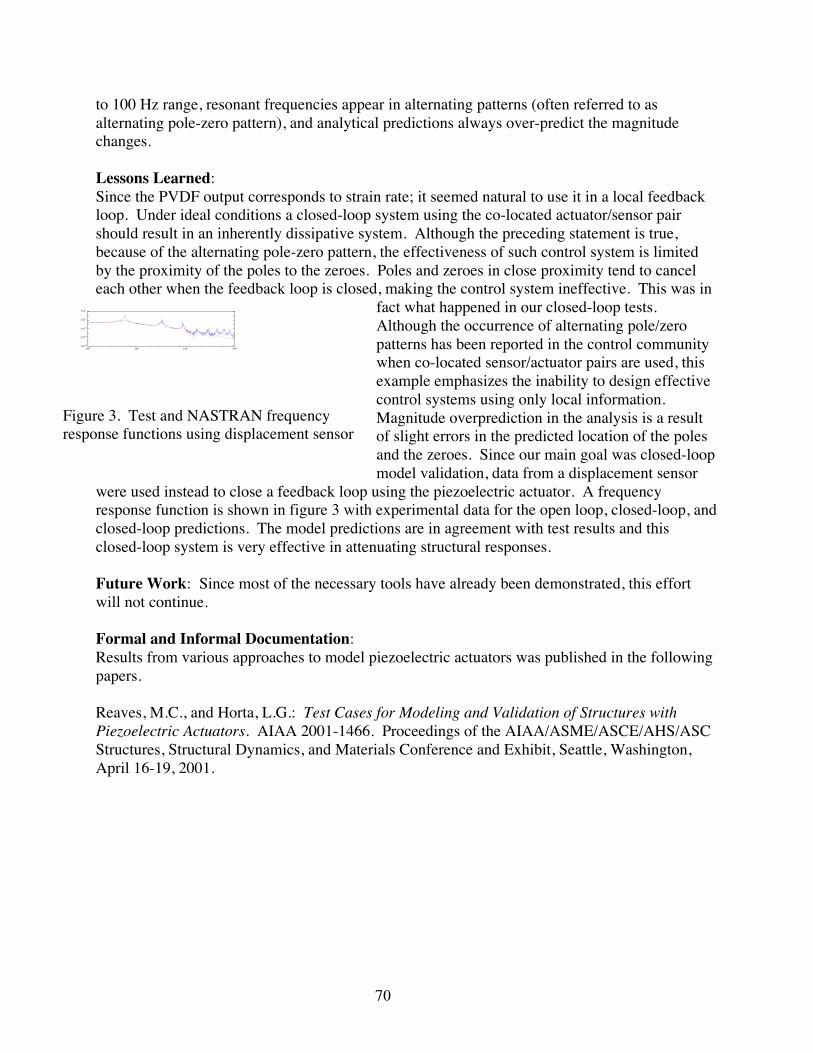
70
to 100 Hz range, resonant frequencies appear in alternating patterns (often referred to asalternating pole-zero pattern), and analytical predictions always over-predict the magnitudechanges.
Lessons Learned:Since the PVDF output corresponds to strain rate; it seemed natural to use it in a local feedbackloop. Under ideal conditions a closed-loop system using the co-located actuator/sensor pairshould result in an inherently dissipative system. Although the preceding statement is true,because of the alternating pole-zero pattern, the effectiveness of such control system is limitedby the proximity of the poles to the zeroes. Poles and zeroes in close proximity tend to canceleach other when the feedback loop is closed, making the control system ineffective. This was in
fact what happened in our closed-loop tests.Although the occurrence of alternating pole/zeropatterns has been reported in the control communitywhen co-located sensor/actuator pairs are used, thisexample emphasizes the inability to design effectivecontrol systems using only local information.Magnitude overprediction in the analysis is a resultof slight errors in the predicted location of the polesand the zeroes. Since our main goal was closed-loopmodel validation, data from a displacement sensor
were used instead to close a feedback loop using the piezoelectric actuator. A frequencyresponse function is shown in figure 3 with experimental data for the open loop, closed-loop, andclosed-loop predictions. The model predictions are in agreement with test results and thisclosed-loop system is very effective in attenuating structural responses.
Future Work: Since most of the necessary tools have already been demonstrated, this effortwill not continue.
Formal and Informal Documentation:Results from various approaches to model piezoelectric actuators was published in the followingpapers.
Reaves, M.C., and Horta, L.G.: Test Cases for Modeling and Validation of Structures withPiezoelectric Actuators. AIAA 2001-1466. Proceedings of the AIAA/ASME/ASCE/AHS/ASCStructures, Structural Dynamics, and Materials Conference and Exhibit, Seattle, Washington,April 16-19, 2001.
100 101 102 10310
-6
10-4
10-2
100
102
Figure 3. Test and NASTRAN frequencyresponse functions using displacement sensor

71
Figure 1. Photograph of ATW bending test
Probabilistic Approach to Model Update of the Aerostructures Test Wing (ATW)
Lucas G. Horta 757-864-4352, [email protected] C. Reaves 757-864-1306, [email protected]
Structural Dynamics Branch, Structures, and Materials CompetencyDavid F. Voracek, 661-276-2463, [email protected]
Dryden Flight Research Center
Background and Objectives:NASA Dryden Flight Research Center has developed a technique to predict the onset of flutterby analyzing flight data from test points at which the aircraft is stable. A flight experiment,using the Aerostructures Test Wing (ATW), was formulated to validate the technique. NASALangley Research Center was asked to develop the structural excitation scheme and to supportthe modeling effort. After initial static and dynamic test data were obtained, correlation of testversus analysis showed significant discrepancies. Often finite element parameters need to beadjusted to get better agreement with experimental results. Normally, model updating isheuristic and often performed by a skilled analyst with in-depth understanding of the modelassumptions. Since parameter uncertainties play a key role in understanding and improvinganalytical models, probabilistic analysis tools, developed for reliability and risk analysis, havegreat potential for guiding the update process.
Benefits over Existing Systems:To our knowledge this is the first time probabilistic tools have been used at NASA LaRC toupdate finite element models. Understanding parameter uncertainty is critical to reconcilemodels with test results. The present study demonstrates new capabilities of analysis toolsavailable to most users.
Previous Work: Previous studies concentrated on enhancement and validation of commercial modeling tools tomodel structures with piezoelectric actuators and the implementation of optimization tools foroptimal placement of piezoelectric actuators and sensors.
Accomplishments and Lessons Learned:Prior to certifying the ATWconfiguration for flight, several staticand dynamic tests were performed.Load certification up to 125 percent ofdesign limit loads were conducted inboth bending and torsion. Figure 1shows a side view photograph of thebending test setup. Displacement datawere measured using linear variabledifferential transducers (LVDT) at eightlocations on the wing. In the study,Young’s modulus was one of theselected parameters for the uncertainty analysis because reported values vary significantly.
Load
WingLVDT

72
Other parameters selected for study affected the root bending stiffness. All parameters wereassigned an upper and lower bound with uniform distribution functions to convey our lack ofknowledge and confidence in the nominal values.
A commercial probabilistic analysis code named UNIPASS was used to determine the mostprobable point (MPP) solution for both bending and torsion. Figure 2 shows a summary of
results using data from the torsion tests only. The upper left plot shows a comparison of thewing displacements before and after the parameter updating as indicated in the bottom table.
Also shown in the upper right table are the predicted and measured displacements. Comparisonof numerical values from tests and the updated solution showed significant improvement overresults using the nominal values. Nevertheless, individual errors remained as high as 40 percent.For the torsion solution, parameter changes up to 24 percent are required to reconcile test withanalysis. Also shown in the table is the probability of the solution being the true solution asPf=0.63. Solutions for this class of problems are heavily dependant upon the initial distributionfunctions. Subsequent work to improve results needs to use a Bayesian approach to allow for theinitial parameter distribution functions to be updated based on experimental data.
Future Work: Complete the model update for the dynamic case and document results.
Formal and Informal Documentation:Horta, L. G., Reaves, M. C., and Voracek, D. F. A Probabilistic Approach to Model Update.Proceedings of the First Annual Probabilistic Methods Conference, June 18-19, 2001, NewportBeach, California. Also NASA TM-2001-18097.
External Partners and Their Accomplishments:David F. Voracek from NASA Dryden Flight Research Center, ATW flight experiments projectlead.
Component Parameters Nominal Values
MPP Torsion Pf=0.63
Spar 11E
(lbs/in 2) 71058.1 × 71077.1 ×
Skin
sE11
(lbs/in 2) 61067.2 × 61064.2 ×
Skin
sE22
(lbs/in 2) 61067.2 × 61064.2 ×
Core
cE(lbs/in 2) 3101.13 ×
31097.9 ×
Root
bk( lbs/in) 4102.2 ×
41054.2 ×
Original Model
Test
Updatewith torsionparameters
Wing leading edge
Torsion
test
Original Model
Torsion
MPP Torsion Solution Pf=0.63
Loc Disp. (in)
Mean Std. Dev. Disp. (in)
Disp. (in)
1 0.437-(5.14e-4) 0.442 0.425 11 0.220-(1.45e-4) 0.295 0.261 56 0.102-(2.33e-4) 0.131 0.129 66 0.095-(1.95e-4) 0.107 0.098 67 0.064-(2.11e-4) 0.090 0.090 77 0.058-(2.03e-4) 0.076 0.069
100 0.002-(1.90e-4) 0.013 0.013 110 0.003-(1.99e-4) 0.007 0.006
Figure 2. Model update results for ATW torsion case

73
Figure 1. Aerostructure Test Wing (ATW)with piezoelectric actuators
10-2
100
102 Acceleration at wing location 1
AnalysisTest
Magnitudein/sec^2/V
Frequency (Hz)
101 10210-2
100
102 Acceleration at wing location 11
AnalysisTest
Magnitudein/sec^2/V
Frequency (Hz)
102101
Figure 2. Test vs. analysis frequency responsefunction at wing tip locations
Aerostructures Test Wing (ATW) Excitation System Design and Performance Test
Mercedes C. Reaves 757-864-1306, [email protected] G. Horta 757-864-4352, [email protected]
Structural Dynamics Branch, Structures and Materials CompetencyDavid F. Voracek, 661-276-2463, [email protected]
Dryden Flight Research Center
Background and Objectives:A problem in validating flight flutter prediction techniques is that flight flutter data near theonset of instability is extremely challenging to obtain due to flight safety concerns. NASADryden Flight Research Center developed a flight flutter prediction technique that predicts theonset of instabilities by analyzing flightdata from test points at which the aircraftis stable. A flight experiment, called theAerostructures Test Wing (ATW), wasformulated to validate the technique.Adequate structural excitation was animportant requirement to the success ofthe flutter test. The Structural DynamicsBranch at NASA Langley ResearchCenter (LaRC) was assigned the task ofproviding an optimal piezoelectricactuator configuration to initiate and/orcontrol flutter modes of the aerostructures test wing.
Benefits over Existing Systems:NASA LaRC experience in the use of piezoelectric actuators for structural vibration control aswell as the intrinsic characteristics of piezoelectric actuators: lightweight, low powerrequirements, broadband excitation capability and easy of use, met all the applicationrequirements.
Previous Work: Previous studies concentrated onenhancement and validation of commercialmodeling tools to model structures withpiezoelectric actuators and theimplementation of optimization tools foroptimal placement of piezoelectricactuators and sensors.
Accomplishments and Lessons Learned:Optimal placement of actuators using abaseline ATW finite element model wascompleted. Size of actuators was selectedbased on mass and stiffness constraints. A

74
ATW Bending
ATW Torsion
With Excitation
With out Excitation
Figure 3. Accelerometer response with andwithout piezoelectric excitation
total of six 3” x 1.75” actuators were placed on the structure, 3 on the top surface and 3 on thebottom surface of the wing skin. Figure 1 shows a picture of the ATW with the surface mountedpiezoelectric actuators. Analytical simulations and ground vibration tests verified that responselevels from the wing structure were significantly above the noise floor for accelerometer sensors.Figure 2 shows the correlation of test andanalysis. The first frequency resonance waspredicted within 2 percent and the secondresonance within 11 percent. Results of thepiezoelectric actuation system performanceduring the flight, comparing the response fromthe excitation system to natural atmosphericturbulence are shown in figure 3. Theatmospheric turbulence did not excite thetorsion mode of the wing at this flight condition.The piezoelectric excitation clearly made thismode observable during the flight. Thepiezoelectric excitation also provided a higherresponse in the bending mode of the ATW.These results clearly demonstrate our ability tomodel and analyze ‘smart structures’ at theearly stages of the design process. Therefore reducing cost and the design-analysis-test cycle offlight test articles such as the ATW.
Future Work: Task has been completed.
Formal and Informal Documentation:Voracek, D., Reaves, M. C., Horta, L. G., Potter, S. Ground and Flight Test StructuralExcitation using Piezoelectric Actuators. Submitted to AIAA 2002,AIAA/ASME/ASCE/AHS/ASC Structural Dynamics and Materials Conference.
External Partners and Their Accomplishments:David Voracek from NASA Dryden Flight Research Center, ATW flight experiments projectlead.

75
Development of a Self-Sensing Piezoelectric Actuator
Lucas G. Horta 757-864-4352, [email protected] C. Reaves 757-864-1306, [email protected] C. Horner, 757-864-1684, [email protected]
Structural Dynamics Branch, Structures and Materials Competency
Background Information:Piezo-electric actuators have been used and studied for many engineering applications becausethey provide for lightweight yet powerful actuation systems. Often integration of the actuatoronto the host structure is easy,but the means to measure theinduced actuation levels locallyare not. Several studies havebeen performed using the samepiezoceramic elements for bothsensing and actuation, oftenreferred to as a sensor actuator.Although this is an effective wayto sense the motion of the hoststructure, the voltage levels of thedrive and sensor signals areorders of magnitude apart. In addition, the electronics required to recover the sensor signal is farmore complex. Typical self-sensing electronic circuits are designed as a multi-layer circuit toisolate the drive signal from the sensor signal.
Objective:The main objective of this work was toexperimentally demonstrate a self-sensingpiezoelectric actuator.
Accomplishments and Lessons Learned:A new self-sensing design was developed andtested where part of the actuator material wascarved out (isolated) for sensing. A prototypeis shown in the figure 1 photo. Of course,carving out a portion of the material for sensing reducesthe amount of material available for actuation,but this is a small price to pay when comparedto the simplicity of this arrangement, whichrequires no additional electronics.
Straining of the sensor part is proportional tothecharge generated in the material. For the
Figure 1. Self-sensing actuator
Actuator
Senso
10-5
0.0001
0.001
0.01
0.1 1 10
TestCurrent-Source
Figure 2. Frequency response of self-sensing actuator
Freq (Hz)
appvv

76
study undertaken, the main goal was to show the ability to sense the induced charge/strain whileactuating the material. To accomplish this, the self-sensing actuator was bonded onto a clampedaluminum beam. This allows transferring of strain from the actuator region to the sensor region.To properly validate results from the sensor, one would need to calibrate the sensor using thegeometry and some known input strain. This was beyond the initial goal. To examine the sensoroutput, the sensor circuit can be modeled in various ways. Since charge is being generated, acurrent source analogy comes to mind. The equation representing the circuit is given by
+
=RCs
Rs
v
v
app 1γ , where v is the induced voltage, appv is the applied actuator voltage, R is the
load/leakage resistor, C is the capacitance, s is the Laplace’s transform, and γ is a calibrationcapacitance. For the actuator/sensor combination shown in figure 1, the measured capacitancewas C= 16.4 nF. Curve-fitting the test data using this circuit equation resulted in R=
61038.5 × ohms and a gain value of 1310614.5 −×=γ F. A comparison of the test data with thecurve-fitted model is shown in figure 2. Although the fitted values are in error for the lowfrequency region, the break frequency is predicted well. With this combination of resistor andcapacitor the break frequency for the electronics circuit is HzRC 8.1/1 = . Below this frequency,the sensor output is proportional to the strain rate but above it is proportional to strain. In thetransition region near the break frequency the sensor output cannot be used as either strain orstrain rate. To use the output voltage of the sensor as a signal proportional to strain, a factor of10 or higher frequency separation should be observed between the frequency region of interestand the circuit frequency.
Future Work:This simple study demonstrated the ability to sense and command signals in very close proximitywithout corrupting the sensor data. Many variations of the configuration are possible tominimize the sensor area while maximizing the actuator output. Ingenious ways to calibrate thesensor are also needed to validate analytical models of the self-sensing actuator, however, nofurther work in this area is anticipated due to funding constraints.

77
Biologically-Inspired Flight Systems FY 2001 Research Summaries

78
Biologically-Inspired Flight Concepts
Barry S. Lazos, 757-86-45731, [email protected] Physics and Control Branch, Aerodynamics, Aerothermodynamics and Acoustics
CompetencyBackground Information:Commercial aircraft configurations have not significantly changed for decades. This is becausefew advancements have been made in the areas of drag reduction, flow control and noiseabatement to prompt such changes. Certain morphological features found on avian and marinecreatures are expected to limit energy consumption, increase maneuverability, and reduce noiselevels. Application of similar features to a mechanical flight system may provide improvementsin these same areas.
Objective of Current Work:The objective of this work is to identify morphologies in nature that have the potential for activeor passive drag and/or noise reduction as well as flow control for application to subsonictransport aircraft, small scale Unmanned Aerial Vehicles (UAV), and marine vehicles.
Benefits over Existing Systems:This work has the potential to improve drag, noise and control characteristics of manned andunmanned aerial and marine vehicles using highly evolved methods found in nature. Thebenefits include energy savings, lower noise and pollution levels, and improved safety andmaintainability features.
Previous Work on This Work Package:Work began in this area in 2000 with a comprehensive literature review of existing knowledge incontrol techniques found in biological systems. (See below for reference.)
Current Year Accomplishments:1. Extensive literature review of the state-of-knowledge in induced drag and control techniques.
Results revealed induced drag can account for between one-third and one-half of the drag ofa commercial aircraft in cruise. Induced drag reduction methods may additionally diminishwake vortex intensity and noise levels.
2. Identification of several promising morphologies and selection of three biologically-inspiredwing configurations. One wing was modeled directly after the wing of a seagull in glidingflight (Gull Wing), another was inspired by the fin morphology of sharks (Shark Wing), andthe last was inspired by the wing shape of some shore birds and supported by theory (HECSWing).
3. Tests of these three wing configurations were conducted in the BART facility. Data acquiredincluded forces and moments, model deflection, and wing surface pressure and shear-stresstopologies. Loads data show that the HECS (Hyper-Elliptic Cambered Span) wing providesa 14 percent average improvement in lift-to-drag over the planar-elliptic wing used as abaseline (see figure 1).
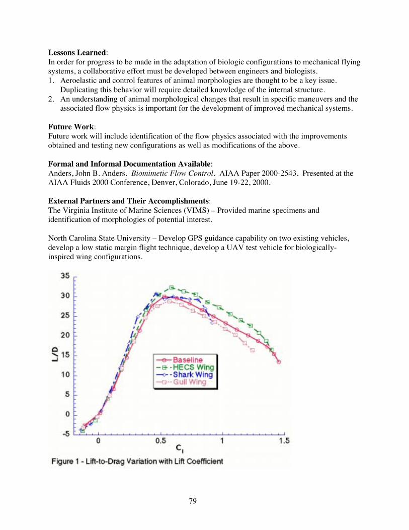
79
Lessons Learned:In order for progress to be made in the adaptation of biologic configurations to mechanical flyingsystems, a collaborative effort must be developed between engineers and biologists.1. Aeroelastic and control features of animal morphologies are thought to be a key issue.
Duplicating this behavior will require detailed knowledge of the internal structure.2. An understanding of animal morphological changes that result in specific maneuvers and the
associated flow physics is important for the development of improved mechanical systems.
Future Work:Future work will include identification of the flow physics associated with the improvementsobtained and testing new configurations as well as modifications of the above.
Formal and Informal Documentation Available:Anders, John B. Anders. Biomimetic Flow Control. AIAA Paper 2000-2543. Presented at theAIAA Fluids 2000 Conference, Denver, Colorado, June 19-22, 2000.
External Partners and Their Accomplishments:The Virginia Institute of Marine Sciences (VIMS) – Provided marine specimens andidentification of morphologies of potential interest.
North Carolina State University – Develop GPS guidance capability on two existing vehicles,develop a low static margin flight technique, develop a UAV test vehicle for biologically-inspired wing configurations.

80
Autonomous/Collaborative Control of Aeroelastic Fixed Wing Micro Aerial Vehicles:Characteristics of Fixed Wing Micro-UAVs
Martin R. Waszak, 757-864-4015, [email protected] and Control Branch, Airborne Systems Competency
Micro aerial vehicles have been the subject of considerable interest and development over thelast several years. The majority of current vehicle concepts rely on rigid fixed wings or rotors.An alternate design based on an aeroelastic membrane wing concept has also been developedthat has exhibited desired characteristics in flight test demonstrations and competition. Theaeroelastic fixed wing micro aerial vehicle concept has been the subject of research to determinethe degree to which the innovative membrane wing influences vehicle stability and control. Thevehicle will subsequently be the basis for development of autonomous and collaborative controlsystem design and implementation.
Figure 1. Micro aerial vehicle and wind tunnel arrangement
Wind tunnel testing was performed in NASA Langley’s Basic Aerodynamcis Research Tunnel(BART) to identify the aerodynamic properties of the vehicle, and in particular the effects of themembrane wing. The results indicate that the elastic membrane wing allows the vehicle toachieve higher angles of attack without stalling (see figure 2).
0.0
1.0
2.0
3.0
4.0
-10 0 10 20 30 40 50
RigidSomewhat FlexibleVery Flexible
CL
Angle of Attack (deg)Figure 2. Lift curves for wings of variouslevels of flexibility
-0.60
-0.40
-0.20
0.0
0.20
0 0.5 1 1.5 2 2.5 3 3.5 4
Undeformed ShapeAoA=0 degAoA=10 degAoA=20 degAoA=30 deg
VerticalPosition
(in)
Chordwise Location (in)
Midspan
Figure 3. Deformed shapes of midspan wing section for various angles of attack
81
This fact coincides with significant static deformation of the wing under load, particularly athigher angles of attack (AoA), and is accompanied by extensive high frequency membranevibration. The static deformation allows the wing to achieve a smaller effective angle of attackat high vehicle attitudes (see figure 3). Flow visualization suggests that the wing deformationcontributes to weaker wing tip vortices. It is likely that there is some link between the vortexstrength and structure, membrane billowing, and the stall resistance of the elastic membranewings. The consequences of these various effects require additional study.
The vehicle was shown to be statically stable in all axes and that the nondimensional staticstability derivatives of the vehicle were found to be generally larger than for typical pilotedaircraft. Because the vehicle has been “tuned” using flight test experiments it is likely that therelatively large pitch and yaw stability and large dihedral effect enhance the vehicle’s flyingqualities. The vehicle trims near the maximum L/D, but the maximum L/D is significantly lowerthan other comparable micro aerial vehicles. It was also shown that streamlining of the fuselageresulted in significant improvement in the lift to drag ratio. Subsequent design changes havemade better use of streamlining to improve vehicle performance.
Additional wind tunnel tests and analytical studies of the aeroelastic fixed wing micro aerialvehicle are planned or underway. In particular, a six degree-of-freedom quasi-static dynamicsimulation model of the vehicle is being developed. Additional studies will emphasize efforts todevelop additional understanding of the physical properties of the membrane wing concept anduse this understanding to improve the design of the vehicle and pursue other aerospaceapplications.
The vehicle concept was developed at the University of Florida by a team led by Dr. Peter Ifju.A cooperative agreement (NCC-1-397) has been established to coordinate development of thevehicle concept and research being conducted at NASA. The University of Florida team hasdeveloped a horizon detection system that uses the onboard video camera image to detect thelocal horizon line. The horizon line is used to determine the pitch and roll attitude of the vehicleand that information is used to control the vehicle attitude and thereby significantly enhance thecontrollability of the vehicle. They have also continued to refine the vehicle design using thewind tunnel test results described above.
References:1. Waszak, M. R.; Jenkins, L. N.; and Ifju, P. Stability and Control Properties of an
Aeroelastic Fixed Wing Micro Aerial Vehicle. AIAA Paper No. 2001-4005. Presented at theAIAA Atmospheric Flight Mechanics Conference, Montreal, Quebec, Canada,August 6–9, 2001.
2. Fleming, G. A.; Bartram, S. M.; Waszak, M. R.; and Jenkins, L. N. Projection MoiréInterferometry Measurements of Micro Air Vehicle Wings. SPIE Paper No. 4448-16.Presented at the SPIE conference on Optical Diagnostics for Fluids, Solids, and Combustion,part of the SPIE International Symposium on Optical Science and Technology, San Diego,California, July 29-August 3, 2001.

82
3. Ettinger, S. M.; Nechyba, M. C.; Ifju, P. G.; and Waszak, M. R. Towards Flight Autonomy:Vision-Based Horizon Detection for Micro Air Vehicles. To appear in proceedings of AIAAAerospace Sciences Meeting, Reno, Nevada, January 2002.
4. Ettinger, S. M.; Nechyba, M. C.; Ifju, P. G.; and Waszak, M. R. Vision-Guided FlightStability and Autonomy for Micro Air Vehicles. To appear in proceedings of AIAAAerospace Sciences Meeting, Reno, Nevada, January 2002.
5. Ifju, P. G.; Jenkins, D. A.; Ettinger, S. J.; Lian, Y.; Shyy, W.; and Waszak, M. R.: Flexible-Wing-Based Micro Air Vehicles. AIAA Paper No. 2002-0705. To appear in proceedings ofAIAA Aerospace Sciences Meeting, Reno, Nevada, January 2002.

83
Component Technologies
Robert Fox, 757-864-5468, [email protected] Shams, 757-864-8156, [email protected]
Microelectronics and Technical Support, Systems Engineering Competency
Background Information:Biologically-inspired devices, particularly flight vehicles, are usually small-scale, lightweight,and operate autonomously. A common requirement for these systems is integrated andlightweight electronics and efficient sources of power. In addressing these requirements, anumber of promising technologies were investigated in the area of avionics, wirelesscommunications, and fuel cells.
Objective of Current Work:A miniature, lightweight, efficient and inexpensive navigation system is a requirement forstability and guidance of a highly functional autonomous vehicle. The navigation system beingdeveloped at LaRC will be small enough to fit into a micro vehicle. It will have air/ground speedcontrol, altitude control, turn coordination, GPS, telemetry, autonomous take off, flight andlanding. The critical parts of a navigation system are: GPS, data logger, electronics for altitudecontrol, telemetry and a programmable microprocessor. Technologies needed to support thenavigation system development are: flexible multi-layer circuits, flip chip technology, wirebonding, surface mount, integrated passives and actives.
This work also pursued the development of an inflation and deflation mechanism capable ofmorphing the shape of a simple or complex (e.g., bio-inspired) structure. The mechanism, basedon out-gassing from a reversible electrochemical cell, will be small, lightweight, reversible, andcontain no moving parts. The ability to morph shapes using such a mechanism allows for thedevelopment of vehicles for use in terrestrial and space-based exploration and reconnaissancechallenges that are not achievable by mechanical pump based systems.
Benefits over Existing Systems:Existing systems are large and consume too much power to be integrated into an autonomousvehicle. The primary benefits of this work are in reduction of weight and size, increased energydensity of power supplies, and in the multi-function benefits possible with an integrated design.
Previous Work on this Work Package: This work package was a new start in FY 2001.
Current Year Accomplishments:Two high voltage power supplies were designed, proto-typed and tested during the year 2001.The high voltage power supplies are capable of producing 325 volts at five milli amperes and650 volts at five milli amperes. The 325 volt supply is approximately one square inch and the650 volt supply is about two square inches in area at a height of about three quarters of an inch.The circuits use standard electronic components. Recently purchased DC-DC converters willincrease the current level of the high voltage amplifiers to eight milli amperes, while maintainingthe same size and volume. Alternate commercially available DC-DC converters will increase thehigh voltage circuit from eight to sixty milli amperes. Sixty milli amperes is the current limit of

84
the amplifier being used. Higher current DC-DC converters will certainly increase the packagesize by orders of magnitude. Current levels into the hundreds of milli amperes are possible withalternate commercially available amplifiers. Higher current amplifiers generate a tremendousamount of internal heat. Dissipating this heat is a engineering nightmare. Continued work inthis area (ASICs and electronic die-APL or hybrid circuits) will reduce the area of the highvoltage power supplies by more than fifty percent. The development the power suppliesreceived funding from a number of sources in the year 2001.
Wireless communications systems were developed in the year 2001 for shape control (morphingusing a direct current bias), applications requiring repetition (i.e., flapping-variable voltage andfrequency) and relaying information from a sensor to a remote location or requiring data logger.The ideal wireless system will have adequate battery life, transmit over a reasonable distance,avoid EMI, provide plug and play compatibility with many products from many companies, beinfinitely small, self powering, self configuring, self calibrating, self locating and provide asecure RF signal for communication. The commercial wireless systems developed at LaRC usescience band frequencies of 418MHz, 433MHz and 900MHZ. The wireless systems consume300 milli watts of power, require no FCC license to operate and have a range of nearly 1000 feetin all directions. An analog signal imposed on a carrier frequency is used to produce a DC biasfor shape control. Changing the DC bias level will alter the strain produced by the actuator. If arepetitive motion is required (flapping), a sine wave is imposed on the transmitter’s carrierfrequency. The sine wave is generated by a single electronic chip with variable amplitude andfrequency. The wireless systems for shape control and repetitive motion will have the samevoltage and current potential as that of the previously mentioned amplifiers. Sensors have beeninterfaced into the LaRC wireless system to relay critical flight data back from a biomimeticvehicle. Funding for this work during the year 2001 came from a number of places.
Future Work:Funding sources for next year have not been secured, however, the initial work has yieldedseveral paths for continuation and additional design objectives remain.
External Partners and Their Accomplishments:This work involved contracts with Composite Optics, Applied Physics Labs and University ofArkansas.

85
Airmass Guidance
David E. Cox, 757-864-6658, [email protected] and Control Branch, Airborne Systems Competency
Background Information:Small and mid-scale Unmanned Air Vehicle (UAV) systems have many potential applications inboth military and civilian sectors. For example, they can provide visual reconnaissance of anarea, be deployed in search and rescue operations, fly circuits to detect forest fires, providemobile and secure communications relays, or gather detailed in-situ measurements for weatherprediction. A common requirement for all of these missions is the endurance of the system -how long can it loiter in, or fly a circuit around, a prescribed area.
Improving lift-to-drag ratios, increasing the efficiency of propulsion systems, and increasing theenergy density of fuels are direct (and important) approaches to the problem of endurance.This work, however, seeks a different and biologically-inspired approach - that of extractingenergy from an unstable atmosphere during flight. The wandering albatross is able to soar forhours without flapping its wings as it makes use of vertical wind gradients in a technique knownas dynamic soaring. Other birds circle in thermals to gain altitude and extend hunting rangewithout expending additional energy.
For low-speed and lightweight UAVs the effects of atmospheric winds are not negligible, andcan be a significant source of energy. The technical questions that this work package seeks tounderstand are: what instrumentation is required, how is a guidance law determined, and how isthe necessarily autonomous guidance path integrated with the prescribed-waypoint paths foundin many applications.
Objective of Current Work:The current works seeks to develop guidance algorithms that enable an instrumented UAV toadjust its trajectory between waypoints, or choose a loitering path such that it takes advantage offavorable winds and updrafts and mitigates the effect headwinds and of sinking air.
Benefits over Existing Systems:Existing systems fly prescribed trajectories that are independent of atmospheric effects.By considering these effects it is expected that, particularly for small and low speed UAVs,endurance can be significantly enhanced.
Previous Work on this Work Package: This work package was a new start in FY 2001.
Current Year Accomplishments:During FY 2001, an atmospheric modeling package was obtained and ported from a Cray to aLinux computer system. The package is called TASS (Terminal Area Simulation System), andhas been used to model relatively small-scale atmospheric features. The software is essentially aCFD code and produces atmospheres with vertical and horizontal winds and physicallyconsistent variables, such as pressure, temperature, water vapor, etc. Several representative

86
atmospheres have been produced and will be used to pose optimization problems for a flightvehicle.
Also during FY 2001, a suitable aircraft model was developed that includes the ability to imposespatially variable winds that are a relatively large fraction of the flight speed. This model can beflown through the simulated atmosphere to determine the significance of ambient winds on flightpath.
Lessons Learned:A physically realistic atmosphere model was deemed important because it allows a feedbackimplementation of the optimal trajectories to be based on measurements such as pressure andtemperature as well as loads from vertical wind. Potentially, this allows the algorithm to includelogic for finding thermals, rather than just reacting to them. The optimization requirements,however, are for many randomly initiated atmospheres at very high grid density and this is notnumerically feasible. Current plans are to use a few high fidelity simulations to determineparameters a for stochastic atmosphere model. These stochastic models with be suitable fordetermining optimal trajectories, provided only the loads from winds are used for feedback, notcorrelations between temperature, pressure, water vapor, or other physical variables.
Future Work:The work in FY 2002 will concentrate on obtaining optimal trajectories for the existing aircraftmodels and simulated atmospheres. These trajectories will allow evaluation of the benefits ofairmass guidance. From these optimal trajectories a guidance strategy will be determined thatapproximates the optimal, but operates based on feedback from measured variables.
Formal and Informal Documentation Available:Although the area is relatively new, there has been some work on optimal soaring published inthe literature, predominately in the Journal of Technical Soaring. Relevant references include:
1. Sachs, G, Knoll, A., and Lesch, K. Optimal Utilization of Wind Energy for DynamicSoaring. Journal of Technical Soaring, Vol. 15, No. 2, pp. 48-55, 1991.
2. Stojkovic, B. Generalized Speed-to-fly Theory. Journal of Technical Soaring, Vol. 17, No.3, pp 77-83, 1993.
External Partners and Their Accomplishments:This work is being done in conjunction with an ICASE researcher and contract support fromResearch Technology Institute on the TASS software. Their accomplishments are reflected inthe work described above.

87
Dynamics and Control of Resonant Flapping Micro-Aerial Vehicles
Dave Raney, 757-864-4033, [email protected] and Control Branch, Airborne Systems Competency
Background Information:With uncountable civil and military applications, micro-aerial vehicles (MAVs) represent anemerging sector of the aerospace market and may one day become as ubiquitous as cell phones.Although a number of highly capable MAV designs have been generated by several government-funded and commercial endeavors, these designs rely on relatively conventional scaled-downcontrol approaches, and they do not possess the flight agility and versatility that would enablemissions such as rapid flight beneath a forest canopy or within the confines of a building. Inorder to satisfy such mission requirements, it is likely that MAV designs of the future willexploit flapping flight for extreme agility. Many flying insects generate lift through resonantexcitation of an aeroelastically tailored structure: muscle tissue is used to excite a structurewhich exhibits a particular mode shape that has been tuned to generate propulsive lift. A numberof MAV concepts have been proposed that would operate in a similar fashion.1,2 A resonance-based flapping MAV design would challenge the current state-of-the-art in flight control forvehicles with highly transient flight-dynamic characteristics.
Objective of Current Work:This work package does not seek to develop a flapping MAV design. The goal is to developdynamic models and feedback control concepts for vehicle designs in which resonant excitationof an aeroelastically tailored wing structure is used to generate propulsive lift for an extremelyagile MAV.
Benefits over Existing Systems:An extremely agile resonant flapping MAV would exploit unsteady aerodynamic factors such asdynamic stall to transition rapidly between flight modes, and might vary its inertial properties bystowing its wings during high-rate maneuvers. Aerodynamic characteristics, inertial properties,and flight conditions will rapidly vary over an unprecedented range. Developing methodsrequired to control a highly agile flapping MAV will bolster our understanding of unsteady andnonlinear dynamic phenomena in general, and could also have cross-over application totechnologies such as distributed flow control effectors for full-scale aircraft.
Previous Work:Previous work focused on modification of a structural concept from a flexible fixed-wing MAVdesign from the University of Florida. The latex and graphite-epoxy pre-preg structure wasmodified to create wing planforms that were tailored to generate bird-like flapping kinematicswhen excited at their lowest frequency bending mode. Piezoceramic Thunder wafer actuatorswere used to excite the structures at their resonant frequency of approximately 25 Hz (figure 1).Flow visualization revealed the presence of unsteady fluid dynamic structures acting on theflapping wings much like those observed by entomologists at UC Berkeley. 3

88
Current Work/ Lessons Learned:Current research has focused on the evaluation of thin film pvdf strain rate sensors for closed-loop control of the resonating wing structure. A controller has been developed that uses thissensor feedback to drive the wing at its fundamental resonant frequency (figure 2). Tests undertime-varying reduced pressures have confirmed the system's ability to track the resonantfrequency as it varies with aerodynamic damping.
Figure 1. Resonant flapping wing structures and unsteady flow visualization.
Figure 2. Closed-loop resonant capture time histories showing excitation frequency and strain-rate sensor response.
Future Work:Future research will extend the pvdf feedback concept to drive resonant excitation inputs frommultiple actuators for feedback control of flapping kinematics. Another topic that will beinvestigated is the incorporation of Langley-developed electrostrictive polymer actuationmaterials into the resonant flapping system.4 Continued use of reduced pressure testing willprovide data for estimation of aerodynamic damping influence on the resonant frequencies.
External Partners:Under a cooperative agreement with Vanderbilt University, NASA is leveraging off previousDARPA-funded flapping flight research to provide a testbed for dynamic modeling, testing andcontrol design.5 Consultation with researchers at the University of Texas in Austin is providingmechanization and actuation insights from insect and avian morphological perspectives.
0 2 4 6 8 1010
15
20
25
30
35
Res
onan
t F
requ
ency
, H
z
0 2 4 6 8 10-2
-1
0
1
2
3
Left
Win
g S
enso
r S
igna
l, m
V
Excitation Frequency, Hz Strain Sensor Response, mVred: ω initial > ω resonance
blue: ω initial < ω resonance
Time, sec Time, sec

89
Documentation/References:1. Frampton, K. D. An Elastodynamic Ornithoptic Flying Robotic Insect. Informal
Presentation at LaRC Bioflight Workshop, August 10, 2000.2. Raney, David L. Dynamic Modeling and Control of Resonant Micro-Aerial Vehicles.
Informal Presentation at LaRC Bioflight Workshop, August 10, 2000.3. Dickinson, M. H.; Lehmann, F.; Sane, S. P. Wing Rotation and the Aerodynamic Basis of
Insect Flight. Science, Vol. 284, June 1999, pp.1954-1960.4. Frampton, K.D.; Goldfarb, M. Passive Aeroelastic Tailoring for Optimal Flapping Wings.
Proceeding of Conference on Fixed, Flapping and Rotary Winged Vehicles for Very LowReynolds Numbers, Notre Dame, Indiana, June 2000.
5. Pawlowski, Kristin; Su, Ji; Raney, David L.; Siochi, Emilie J. Electroactive Polymers forDevelopment of a Micro-Air Vehicle Wing. SPIE Symposium on Smart Structures andMaterials, March 17-21, 2002, San Diego, California (pending).

90
BIOSANT FY 2001 Research Summary

91
Biologically Inspired Fabrication of Electroactive MAV Wings
Emilie J. Siochi, 757-864-4279, [email protected] Materials & Processing Branch, Structures and Materials Competency
Background Information:Electrospinning is a processing method that yields very fine polymer fibers. The basicexperimental set-up shown below consists of a charged polymer solution that is fed through asmall opening (usually a needle or pipette tip). The charged solution is drawn toward a groundedcollecting plate as a jet. During jet travel, the solvent gradually evaporates, and a chargedpolymer fiber builds up on the collecting plate. The charges on the fibers eventually dissipate, asthey are neutralized by the surrounding environment. The final product of the process is anonwoven fiber mat composed of tiny fibers with diameters on the order of nanometers tomicrons.
Objective of Current Work:The objective of this project is to explore electrospinning as a new processing method ofelectroactive polymers. The goal is to be able to control the deposition and orientation of thefibers being collected on the target to allow fabrication of a material that can be used as anelectrically responsive wing skin.
Accomplishments/Data Obtained:Over the past year, parameters for the proper spinning of an electroactive polymer mat onto anopen target (airframe) were determined. The progress of that task can be seen in theimprovement of the spun wings shown in figures 1a-1c below. Figure 1C was the result ofhaving the best combination of polymer solution characteristics and spinning parameters such asapplied voltage and collecting plate distance, so far. The incorrect combination of any of theabove parameters can result in failure to create a mat between the airframe spars as shown infigure 1a, to a less fibrous material as shown in figure 1b.

92
(A) (B)
(C)Figure 1. Effect of electrospinning parameters on quality of spun wings.
Characterization of the spun mat includes microscopy to investigate the uniformity of fiberdiameters spun. Some examples of the data obtained are shown below:
(A) (B)Figure 2. Scanning electron micrographs of electrospun fibers.

93
Figure 2a shows good uniformity of fiber diameter, with the enlarged photo in figure 2brevealing that fiber diameters are 200 – 400 nm across.
Some of the spun fibers were twisted to form ‘tendons’. These ‘tendons’ were tested forelectroactivity. The best response appeared to be produced by a 3KV sine wave (peak-to-peak)at about 2.8Hz. There was no real force behind this motion, because as soon as a tiny load wasapplied, the motion stopped altogether (the tendon seemed barely able to move under its ownweight.) The largest and thickest tendon appeared to produce no response at all. Surprisingly,the best response was produced by the thinner samples.
For the graphite-epoxy wing with the polymer fiber membrane, the best response appeared to beproduced by a 3KV sine wave at about 6.7Hz. This input produced a barely perceptible vibrationof the wing structure. The motion was very slight and it went away altogether as the inputfrequency was shifted from about 1Hz above or below the (apparently resonant) frequency of6.7Hz.
Lessons Learned:An extensive literature search on electrospinning revealed that it’s a method discovered by LordRayleigh in the late 19th century. However, absence of practical use resulted in its abandonmentso that there was about a 30-year gap where there was no published literature. Interest in thisprocess was rekindled in the ‘70s because of potential biomedical applications. Since then, muchof the literature is results of trial and error experiments to spin fibers from various polymers.There is little research towards a fundamental understanding of how the process can becontrolled to yield fibers of uniform characteristics.
Future Work:Results clearly show that deposition of fibers on the collecting plate is not well controlledyielding randomly oriented mats. Work is underway to modify the experimental set-up tocorrect this problem. It is anticipated that increased orientation will yield greater response toapplied voltage. In addition, suitable fiber and mat analysis methods are being developed inorder to obtain mechanical property information on the spun materials.
TeamThis project is a collaborative effort between researchers in the Advanced Materials andProcessing Branch and the Dynamics and Controls Branch. Members of the AMPB team areKristin Pawlowski, Harry Belvin, Ji Su, Joycelyn Harrison and Mia Siochi. Researchers fromDCB are Dave Raney and Marty Waszak. This research also represents a portion of a largereffort that is funded in the SLMFST project in AVST of NASA Langley.

94
Appendix

95
Morphing Project Team FY 2001
Robert G. Bryant Manager, Smart Technologies [email protected] 757-864-4262
David E. Cox Manager, Biologically Inspired Flight Systems [email protected] 757-864-6658
Nancy M. Holloway Systems Engineering Competency [email protected] 757-864-7849
Lucas G. Horta Manager, Adaptive Structures Morphing [email protected] 757-864-4352
Anna-Maria R. McGowan Manager, Morphing [email protected] 757-864-1700
Sharon L. Padula Aerospace Systems, Concepts & Analysis [email protected] Representative
757-864-2807
Emilie J. Siochi Manager, BIOSANT [email protected] 757-864-4279
Anthony E. Washburn Manager, Micro Aero Adaptive Control [email protected] 757-864-1290

96
Formal Publications
1. Allan, Brian G.; Juang, Jer-Nan; Raney, David L.; Seifert, A.; Pack, Latunia G.; Brown,Donald E. Closed-Loop Separation Control using Oscillatory Flow Excitation. ICASEReport 2000-32.
2. Anders, John B. Anders. Biomimetic Flow Control. AIAA Paper 2000-2543. Presented atthe AIAA Fluids 2000 Conference, Denver, Colorado, June 19-22, 2000.
3. Antcliff, Richard R., McGowan, Anna-Maria R. Active Control Technology at NASALangley Research Center. North Atlantic Treaty Organization, Research & TechnologyOrganization Symposium on Active Control Technology For Enhanced PerformanceOperational Capabilities of Military Aircraft, Land Vehicles And Sea Vehicles,Braunschweig, Germany, May 8-11, 2000.
4. Cabell, R. H., and Gibbs, G. P. Hybrid active/passive control of sound radiation frompanels with constrained layer damping and model predictive feedback control.Proceedings of Noise-Con 2000, December 3-5, 2000, Newport Beach, California.
5. Chen, F. J. Development of Synthetic Jet Actuators for Active Flow Control at NASALangley. Presented at the AIAA Fluid 2000 Conference, AIAA Paper 2000-2405,June 19-22, 2000, Denver, Colorado.
6. Chen, F. J. Virtual Shaping of a Two-dimensional NACA 0015 Airfoil Using Synthetic JetActuator. Submitted to the 1st AIAA Flow Control Conference, June 24-27, 2002,
7. Choi, Sang H., Golembiewski. Walter T., Song, Kyo D. Song. Networked Rectenna Arrayfor Smart Material Actuators. Proceedings of 35th IECEC, AIAA 2000-3066, Las Vegas,Nevada, July 31-August 3, 2000.
8. Choi, Sang, Golembiewski. Walter T., Song, Kyo D., and Bryant, Robert G. NetworkedRectenna Array with Power Allocation and Distribution Circuit for Smart MaterialActuators. SPIE’s 8th International Symposium on Smart Structures and Materials,Newport Beach, California, Vol. 4334, pp. 372-381, March 4-8, 2001.
9. Contract report for ATI demonstrator, model # RBL-01-0183.
10. Contract report for DEI demonstrator, model # RBL-01-0184.
11. Cook, Andrea M. Genetic Algorithm Approaches to Optimizing the Location and Numberof Smart Actuators on an Aircraft Wing. Master’s Thesis, Purdue University, December2000.
12. Cook, Andrea M. and Crossley, William A. Investigation of GA Approaches for SmartActuator Placement for Aircraft Maneuvering. 39th AIAA Aerospace Sciences Meeting,January 2001, Reno, Nevada.

97
Formal Publications (Cont’d)
13. Dunne, J. P., Pitt, D. M., White E. V. and Garcia, E.: Ground Demonstration of the SmartInlet. AIAA Paper 2000-1630. Presented at the 41st Structures, Structural Dynamics, andMaterials Conference, April 3-6, 2000, Atlanta, Georgia.
14. Ettinger, S. M.; Nechyba, M. C.; Ifju, P. G.; and Waszak, M. R. Towards FlightAutonomy: Vision-Based Horizon Detection for Micro Air Vehicles. To appear inproceedings of AIAA Aerospace Sciences Meeting, Reno, Nevada, January 2002.
15. Ettinger, S. M.; Nechyba, M. C.; Ifju, P. G.; and Waszak, M. R. Vision-Guided FlightStability and Autonomy for Micro Air Vehicles. To appear in proceedings of AIAAAerospace Sciences Meeting, Reno, Nevada, January 2002.
16. Fleming, G. A.; Bartram, S. M.; Waszak, M. R.; and Jenkins, L. N. Projection MoiréInterferometry Measurements of Micro Air Vehicle Wings. SPIE Paper No. 4448-16.Presented at the SPIE conference on Optical Diagnostics for Fluids, Solids, andCombustion, part of the SPIE International Symposium on Optical Science andTechnology, San Diego, California, July 29-August 3, 2001.
17. Frampton, K. D. An Elastodynamic Ornithoptic Flying Robotic Insect. InformalPresentation at LaRC Bioflight Workshop, August 10, 2000.
18. Frampton, K.D.; Goldfarb, M. Passive Aeroelastic Tailoring for Optimal Flapping Wings.Proceeding of Conference on Fixed, Flapping and Rotary Winged Vehicles for Very LowReynolds Numbers, Notre Dame, Indiana, June 2000.
19. Fraunhofer USA – Delaware. Fabrication of Gamma Titanium Aluminide Closed-CellFoams. Final Report, September 2001.
20. Harrison, J. S. and Ounaies, Z.: Piezoelectric Polymers. Encyclopedia of Smart Materials,Ed. A. Biderman, John Wiley and Sons, submitted for publication.
21. Horta, L. G., Reaves, M. C., and Voracek, D. F. A Probabilistic Approach to ModelUpdate. Proceedings of the First Annual Probabilistic Methods Conference, June 18-19,2001, Newport Beach, California. Also NASA TM-2001-18097.
22. Ifju, P. G.; Jenkins, D. A.; Ettinger, S. J.; Lian, Y.; Shyy, W.; and Waszak, M. R.: Flexible-Wing-Based Micro Air Vehicles. AIAA Paper No. 2002-0705. To appear in proceedingsof AIAA Aerospace Sciences Meeting, Reno, Nevada, January 2002.
23. Kudva, J. N.; Sanders, B.; Garcia, E.: Overview of the DARPA/AFRL/NASA Smart WingPhase 2 Program. Presented at the SPIE’s 9th Annual Symposium on Smart Structuresand Materials, Vol. 4698, Paper No. 4698-04, 2002. Expected publication date, fall 2002.

98
Formal Publications (Cont’d)
24. Kudva, J. N.; Sanders, B.; Pinkerton-Florance, J.; Garcia, E.: Overview of theDARPA/AFRL/NASA Smart Wing Phase 2 Program. Presented at the SPIE Conference onSmart Structures and Materials, Industrial and Commercial Applications of SmartStructures Technologies, Vol. 4332, Paper No. 4332-48, 2001.
25. Lin, C. and Juang, J. Self-tuning of Design Variables for Generalized Predictive Control.NASA TM-2000-210619.
26. Martin, C. A.; et al: Design, Fabrication and Testing of the Scaled Wind Tunnel Model forthe Smart Wing Phase 2 Program. SPIE’s 9th Annual Symposium on Smart Structures andMaterials, Vol. 4698, Paper No. 4698-05, 2002. Expected publication date, fall 2002.
27. McGowan, A. R. Research on Adaptive Aerospace Vehicle Technologies at NASA LangleyResearch Center. Adaptronic Congress, Paper 1, Berlin, Germany, April 2001.
28. McGowan, A-M. R., Horta, L. G., Harrison, J. S., and Raney, D. L. Research Activitieswithin NASA’s Morphing Program. RTO AVT Specialist Meeting on "Structural Aspectsof Flexible Aircraft Control," RTO MP-36, Paper 13, Ottawa, Canada, October 1999.
29. McGowan, A-M., R.: Research and Future Directions on Smart Structures and Materialsin Aerospace Vehicles. Presented at the 39th Annual Aircraft Symposium, October 29-31,2001, Gifu, Japan.
30. Pack, L.G., Schaeffler, N.W., Yao, C.S., and Seifert, A. Active Control of Flow Separationfrom the Slat Shoulder of a Supercritical Airfoil. Extended Abstract Submitted to the 1st
AIAA Flow Control Meeting, June 24-27, 2002, St. Louis, Missouri.
31. Padula, Sharon L., Rogers, James L., and Raney, David L. MDO Techniques and NovelAircraft Control Systems. AIAA Paper No. 2000-4848.
32. Padula, Sharon L.; Rogers, James L.; Raney, David L. Multidisciplinary Techniques andNovel Aircraft Control Systems. AIAA Paper No. 2000-4848.
33. Pawlowski, Kristin; Su, Ji; Raney, David L.; Siochi, Emilie J. Electroactive Polymers forDevelopment of a Micro-Air Vehicle Wing. SPIE Symposium on Smart Structures andMaterials, March 17-21, 2002, San Diego, California (pending).
34. Pitt, D. M., Dunne, J. P., White, E. V., Garcia, E.: SAMPSON Smart Inlet SMA PoweredAdaptive Lip Design and Static Test. AIAA-01-1359. Presented at the 42nd Structures,Structural Dynamics, and Materials Conference, April 16-20, 2001, Seattle Washington.
35. Pitt, D. M., Dunne, J. P., White, E. V., Garcia, E.: Wind Tunnel Demonstration of theSAMPSON Smart Inlet. Presented at the 8th Annual International Symposium on SmartStructures and Materials Conference, March 4-8, 2001, Newport Beach, California.

99
Formal Publications (Cont’d)
36. Pitt, D. M.: SAMPSON Smart Inlet First Entry – Test Report. Boeing report,July 24, 2000.
37. Raney, D. L., Montgomery, R. C., Green, L. L. and Park, M. A. Flight Control usingDistributed Shape-Change Effector Arrays. AIAA Paper 2000-1560, April 2000.
38. Raney, David L. Dynamic Modeling and Control of Resonant Micro-Aerial Vehicles.Informal Presentation at LaRC Bioflight Workshop, August 10, 2000.
39. Reaves, M. C., and Horta, L. G.: Test Cases for Modeling and Validation of Structureswith Piezoelectric Actuators. AIAA 2001-1466. Proceedings of theAIAA/ASME/ASCE/AHS/ASC Structures, Structural Dynamics, and MaterialsConference and Exhibit, Seattle, Washington, April 16-19, 2001.
40. Scherer, L. B.; et al: DARPA / AFRL Smart Wing Phase 2 Wind Tunnel Test Results.Presented at the SPIE’s 9th Annual Symposium on Smart Structures and Materials, Vol.4698, Paper No. 4698-07, 2002. Expected publication date, fall 2002.
41. Seifert, A. and Pack, L.G. Active Control of Separated Flows on Generic Configurationsat High Reynolds Numbers. Submitted to AIAA Journal 2001.
42. Smart Materials and Structures – Smart Wing Phase 2. Contract Final Report, ContractNumber F33615-97-C-3213. Expected Publication, Fall 2002.
43. Song, Kyo D., Golembiewski. Walter T., and Choi, Sang H. Design of Power Allocationand Distribution Circuit with Rectenna Array for Smart Material Actuators. Proceedingsof International Symposium on Smart Structures and Microsystems 2000, Hong Kong,October 19-21, 2000.
44. Su, J., Costen, R., and Harrison, J. S.: Design and Fabrication of Bending Actuators UsingElectrostrictive Graft Elastomers. Proceedings of SPIE Smart Structures and Materials,2001.
45. Su, J., Harrison, J. S., and St. Clair, T.: Novel Polymeric Elastomers for Actuation.Proceedings of IEEE International Symposium on Application of Ferroelectrics, 2001.
46. Su, J., Harrison, J. S., St. Clair, T., Bar-Cohen, Y., and Leary, S.: Electrostrictive GraftElastomers and Applications. Proceedings of MRS Fall Meeting, Vol. 600, 2000.
47. Su, J., Ounaies, Z., and Harrison, J. S.: Ferroelectric and Piezoelectric Properties ofBlends of Polyvinylidene-trifluoroethylene and Graft Elastomer. Proceedings of MRS FallMeeting, Vol. 600, 2000.

100
Formal Publications (Cont’d)
48. Su, J., Ounaies, Z., Harrison, J. S., Bar-Cohen, Y., and Leary, S.: ElectromechanicallyActive Polymer Blends for Actuation. Proceedings of SPIE-Smart Structures and Materials,Vol. 3987, pp. 65-72, 2000.
49. Turner*, Travis L.; Lach, Cynthia L.; Cano, Roberto J. Fabrication and Characterizationof SMA Hybrid Composites. SPIE's 8th Annual Internat'l Symposium on Smart Structuresand Materials, March 4-8, 2001, Newport Beach, California, SPIE 4333-60.
50. Turner, Travis L. A New Thermoelastic Model for Analysis of Shape Memory Alloy HybridComposites. Journal Intell. Mat.. Sys. & Struct. 11(5) 382-394, May 2000.
51. Turner, Travis L. Experimental Validation of a Thermoelastic Model for SMA HybridComposites. SPIE's 8th Annual Internat'l Symposium on Smart Structures and Materials,March 4-8, 2001, Newport Beach, California, SPIE 4326-24.
52. Turner, Travis L. Thermomechanical Response of Shape Memory Alloy HybridComposites. NASA TM-2001-210656, January 2001.
53. Venkataraman, S., Zhu, H., Sankar, B.V., and Haftka, R. T. Optimum Design of aFunctionally Graded Metallic Foam Thermal Insulation. Proceedings of the AmericanSociety for Composites-16th Technical Conference, Blacksburg, Virginia, September 9-12,2001.
54. Voracek, D., Reaves, M. C., Horta, L. G., Potter, S. Ground and Flight Test StructuralExcitation using Piezoelectric Actuators. Submitted to AIAA 2002,AIAA/ASME/ASCE/AHS/ASC Structures, Structural Dynamics and MaterialsConference, Denver, Colorado, April 22-25, 2002
55. Wang, D. P.; et al: Development, Control, and Test Results of High Rate, HingelessTrailing Edge Control Surface for the Smart Wing Phase 2 Wind Tunnel Model. Presentedat the SPIE’s 9th Annual Symposium on Smart Structures and Materials, Vol. 4698, PaperNo. 4698-06, 2002. Expected publication date, fall 2002.
56. Washburn, A. E. NASA Micro-Aero-Adaptive Control. SPIE’s 8th Annual InternationalSymposium on Smart Structures and Materials, SPIE paper 4332-39, March 2001.
57. Waszak, M. R.; Jenkins, L. N.; and Ifju, P. Stability and Control Properties of anAeroelastic Fixed Wing Micro Aerial Vehicle. AIAA Paper No. 2001-4005. Presented atthe AIAA Atmospheric Flight Mechanics Conference, Montreal, Quebec, Canada,August 6–9, 2001.

101
Formal Publications (Cont’d)
58. Wilkie, W. K., R. G. Bryant, J. W. High, R. L. Fox, R. F. Hellbaum, A. Jalink, Jr., B. D.Little and P. H. Mirick. Low-Cost Piezoelectric Actuator for Structural ControlApplications. Proceedings of the SPIE, Smart Structures and Materials 2000 - Industrialand Commercial Applications of Smart Structures Technologies, (3991), 323, 2000.
59. Wilkie, W. Keats, High, James W. Design, Fabrication and Characterization of aConformable, High-Performance Anisotropic Piezoelectric Composite Device forStructural Control Applications. NASA TM, draft in progress, December 2001.
60. Wlezien, R. W., Horner, G., McGowan, A. R., Padula, S., Scott, M. A., Silcox R., andSimpson, J. O. The Aircraft Morphing Program. Proceedings of the 37thAIAA/ASME/ASCE/AHS/ASC Structures, Structural Dynamics and MaterialsConference, Long Beach, California, April 1998.
61. Zhu, H., Sankar, B.V., Haftka, R. T., and Venkataraman, S. Minimum Mass Design ofInsulation Made of Functionally Graded Material. Accepted for presentation at the 43rdAIAA/ASME/ASCE/AHS/ASC Structures, Structural Dynamics and MaterialsConference, Denver, Colorado, April 22-25, 2002.

102
2001 Institute for Computer Applications in Science and Engineering (ICASE)Lecture Series on Morphing
http://www.icase.edu/series/Morphing/
In fiscal year 2001, a lecture series was initiated to broaden our awareness of innovativetechnologies and approaches. The lectures were conducted through the ICASE group at LangleyResearch Center.
1. Dudley, Robert: Mechanisms of Animal Flight Maneuverability: Hummingbirds as CaseExample. University of Texas at Austin, May 7, 2001.
2. Morris, Stephen: Micro Air Vehicle Design Optimization and Flight Test Results. MLBCompany, Palo Alto, California, May 23, 2001.
3. Dial, Kenneth: Birds Morphing: Escaping the U-shaped Power Curve and PerformingExtraordinary Maneuverability. The University of Montana, June 29, 2001.
4. Kornbluh, Roy: Dielectric Elastomer Actuators: Muscles that Morph. SRI International,August 7, 2001.
5. Brei, Diann: Smart Material Actuation Systems. University of Michigan, Ann Arbor,August 27, 2001.
6. Carman, Gregory: Investigating the Passive Damping Properties of Active Materials.University of California, Los Angeles, October 3, 2001.
7. Bewley, Thomas: Adjoint and Riccati: Essential Tools in the Analysis and Control ofTransitional and Turbulent Flow System. University of California, San Diego,October 23, 2001.
8. Weisshaar, Terrence: Aeroelastic Tailoring for Energy Efficient Morphing Aircraft -Finding the Right Stuff. Purdue University, October 25, 2001.
9. Chopra, Inderjit : Review on the Status of Application of Smart Structures Technology toRotorcraft Systems. University of Maryland, College Park, October 31, 2001.
10. Grasmeyer, Joel: Perspectives on Micro Air Vehicles and Electronic PackagingAeroVironment, Inc., November 9, 2001.

103
Partnerships and Collaborations in the Morphing Project in Fiscal Year 2001
Adoptech Inc.Advanced Technologies Inc.Air Force Office Scientific ResearchAir Force Research LaboratoriesApplied Physics LabsArizona State UniversityBrown UniversityCincinnati MachineComposite OpticsDefense Advanced Research Projects AgencyDuke UniversityDynamic Engineering Inc.Electric BoatFlorida State UniversityFraunhofer IncGeorgia Tech Research InstituteHampton UniversityInstitute for Defense AnalysisIntegral Wave TechnologiesJohns Hopkins Applied Physics LabJet Propulsion LaboratoryLockheed MartinMississippi State UniversityMassachusetts Institute of Technology
MSC SoftwareNASA Dryden Flight Research CenterNorfolk State UniversityNorth Carolina State UniversityNorthrop Grumman CorporationOffice of Naval ResearchThe Pennsylvania State UniversityPurdue UniversityResearch Technology InstituteTel Aviv UniversityTexas Agricultural & Mechanical UniversityThe Boeing CompanyU. S. ArmyUniversity of ArkansasUniversity of FloridaUniversity of MichiganUniversity of Notre DameUniversity of TennesseeUniversity of Texas at AustinUniversity of WashingtonUniversity of WyomingVanderbilt UniversityVirginia Institute of Marine SciencesVirginia Polytechnic Institute and State University
Partnerships and collaborations with external organizations are a vital part of the research in theMorphing Project.

REPORT DOCUMENTATION PAGEForm Approved
OMB No. 0704-0188
1. REPORT DATE (DD-MM-YYYY)
08-20022. REPORT TYPE
Technical Memorandum4. TITLE AND SUBTITLE
AVST Morphing Project Research Summaries in Fiscal Year 20015a. CONTRACT NUMBER
6. AUTHOR(S)
Anna-Maria R. McGowan
7. PERFORMING ORGANIZATION NAME(S) AND ADDRESS(ES)
NASA Langley Research CenterHampton, VA 23681-2199
9. SPONSORING/MONITORING AGENCY NAME(S) AND ADDRESS(ES)
National Aeronautics and Space AdministrationWashington, DC 20546-0001
8. PERFORMING ORGANIZATIONREPORT NUMBER
L-18204
10. SPONSOR/MONITOR'S ACRONYM(S)
NASA
13. SUPPLEMENTARY NOTESAn electronic version can be found at http://techreports.larc.nasa.gov/ltrs/ or http://techreports.larc.nasa.gov/cgi-bin/NTRS
12. DISTRIBUTION/AVAILABILITY STATEMENTUnclassified-Unlimited Distribution: StandardSubject Category 08Availability: NASA CASI 301-621-0390
19a. NAME OF RESPONSIBLE PERSON
STI Help Desk (email: [email protected])
14. ABSTRACT
The Morphing project at the National Aeronautics and Space Agency’s Langley Research Center is part of the AerospaceVehicle Systems Program Office that conducts fundamental research on advanced technologies for future flight vehicles. Theobjectives of the Morphing project are to develop and assess advanced technologies and integrated component concepts toenable efficient, multi-point adaptability in air and space vehicles. In the context of the project, the word “morphing” is definedas “efficient, multi-point adaptability” and may include micro or macro, structural or fluidic approaches. The current documenton the Morphing project is a compilation of research summaries and other information on the project from fiscal year 2001.The focus of this document is to provide a brief overview of the project content, technical results and lessons learned fromfiscal year 2001.
15. SUBJECT TERMS
Morphing, Micro-Aero-Adaptive Control, Smart Technologies, Adaptive Structural Morphing, Biologically Inspired FlightSystems, BIOSANT
18. NUMBEROFPAGES
108
19b. TELEPHONE NUMBER (Include area code)
(301) 621-0390
a. REPORT
U
c. THIS PAGE
U
b. ABSTRACT
U
17. LIMITATION OFABSTRACT
UU
Prescribed by ANSI Std. Z39.18Standard Form 298 (Rev. 8-98)
3. DATES COVERED (From - To)
5b. GRANT NUMBER
5c. PROGRAM ELEMENT NUMBER
5d. PROJECT NUMBER
5e. TASK NUMBER
5f. WORK UNIT NUMBER
706-32-41-20
11. SPONSOR/MONITOR'S REPORTNUMBER(S)
NASA/TM-2002-211769
16. SECURITY CLASSIFICATION OF:
The public reporting burden for this collection of information is estimated to average 1 hour per response, including the time for reviewing instructions, searching existing data sources,gathering and maintaining the data needed, and completing and reviewing the collection of information. Send comments regarding this burden estimate or any other aspect of thiscollection of information, including suggestions for reducing this burden, to Department of Defense, Washington Headquarters Services, Directorate for Information Operations andReports (0704-0188), 1215 Jefferson Davis Highway, Suite 1204, Arlington, VA 22202-4302. Respondents should be aware that notwithstanding any other provision of law, no personshall be subject to any penalty for failing to comply with a collection of information if it does not display a currently valid OMB control number.PLEASE DO NOT RETURN YOUR FORM TO THE ABOVE ADDRESS.