avx high reliability tantalum capacitors
TRANSCRIPT

AVX High Reliability Tantalum Capacitors
Version 17.11
ww
w.a
vx
.com

Contents
Introduction. . . . . . . . . . . . . . . . . . . . . . . . . . . . . . . . . . . . . . . . . . . . . . . . . . . . . . . . . . . . . . . . . . . . . . . . . . . . . . . . . . . . . . . . . . . . . . . . . . . 2High Reliability Tantalum Applications. . . . . . . . . . . . . . . . . . . . . . . . . . . . . . . . . . . . . . . . . . . . . . . . . . . . . . . . . . . . . . . . . . . . . 3High Reliability Tantalum Chip Specifications . . . . . . . . . . . . . . . . . . . . . . . . . . . . . . . . . . . . . . . . . . . . . . . . . . . . . . . . . . 4-5Group A Test Options . . . . . . . . . . . . . . . . . . . . . . . . . . . . . . . . . . . . . . . . . . . . . . . . . . . . . . . . . . . . . . . . . . . . . . . . . . . . . . . . . . . . . . . . 6High Reliability Specification Requirements Comparison Chart . . . . . . . . . . . . . . . . . . . . . . . . . . . . . . . . . . . . . . . . 6High Reliability Tantalum Chip Product Family - Design Guide . . . . . . . . . . . . . . . . . . . . . . . . . . . . . . . . . . . . . . . . . 7Part Numbering, Test & Packaging Options. . . . . . . . . . . . . . . . . . . . . . . . . . . . . . . . . . . . . . . . . . . . . . . . . . . . . . . . . . . . . . . 8 TAZ Series. . . . . . . . . . . . . . . . . . . . . . . . . . . . . . . . . . . . . . . . . . . . . . . . . . . . . . . . . . . . . . . . . . . . . . . . . . . . . . . . . . . . . . . . . . . . . . . . . 9-30
CWR09 – MIL-PRF-55365/4 Established Reliability, COTS-Plus & Space Level. . . . . . . . . . . . . . . . . . . . . . . . . . . . . . . . 9-12CWR19 – MIL-PRF-55365/11 Established Reliability, COTS-Plus & Space Level . . . . . . . . . . . . . . . . . . . . . . . . . . . . . 13-16CWR29 – MIL-PRF-55365/11 Established Reliability, COTS-Plus & Space Level . . . . . . . . . . . . . . . . . . . . . . . . . . . . . 17-22TAZ HRC5000 Medical Implantable Grade . . . . . . . . . . . . . . . . . . . . . . . . . . . . . . . . . . . . . . . . . . . . . . . . . . . 23-27TAZ HRC6000 Medical Implantable Grade . . . . . . . . . . . . . . . . . . . . . . . . . . . . . . . . . . . . . . . . . . . . . . . . . . . 28-30
TCP SERIES - DSCC 09009 . . . . . . . . . . . . . . . . . . . . . . . . . . . . . . . . . . . . . . . . . . . . . . . . . . . . . . . . . . . . . . . . . . . . . . . . . . . . 31-33TBJ Series . . . . . . . . . . . . . . . . . . . . . . . . . . . . . . . . . . . . . . . . . . . . . . . . . . . . . . . . . . . . . . . . . . . . . . . . . . . . . . . . . . . . . . . . . . . . . . . 34-61
CWR11 – MIL-PRF-55365/8 Established Reliability, COTS-Plus & Space Level . . . . . . . . . . . . . . . . . . . . . . . . . . . . . . 34-37COTS-PLUS . . . . . . . . . . . . . . . . . . . . . . . . . . . . . . . . . . . . . . . . . . . . . . . . . . . . . . . . . . . . . . . . . . . . . . . . . . . . . . . . . . . . . 38-48COTS-PLUS – SRC9000 Space Level . . . . . . . . . . . . . . . . . . . . . . . . . . . . . . . . . . . . . . . . . . . . . . . . . . . . . . . . . . . . . . . 49-55DSCC Dwgs 07016 & 95158 . . . . . . . . . . . . . . . . . . . . . . . . . . . . . . . . . . . . . . . . . . . . . . . . . . . . . . . . . . . . . . . . . . . . 56-61
T4J HRC4000 Implantable Non Life Support and Non Implantable Life Support. . . . . . . . . . . . . . . . . 62-66TBM Multianode. . . . . . . . . . . . . . . . . . . . . . . . . . . . . . . . . . . . . . . . . . . . . . . . . . . . . . . . . . . . . . . . . . . . . . . . . . . . . . . . . . . . . . . . . 67-72
Tantalum Ultra Low ESR & Space Level . . . . . . . . . . . . . . . . . . . . . . . . . . . . . . . . . . . . . . . . . . . . . . . . . . . . . . 67-69Tantalum Ultra Low ESR COTS-Plus. . . . . . . . . . . . . . . . . . . . . . . . . . . . . . . . . . . . . . . . . . . . . . . . . . . . . . . . . . 70-72
TBC Series . . . . . . . . . . . . . . . . . . . . . . . . . . . . . . . . . . . . . . . . . . . . . . . . . . . . . . . . . . . . . . . . . . . . . . . . . . . . . . . . . . . . . . . . . . . . . . . 73-84CWR15 – MIL-PRF-55365/12 Established Reliability, COTS-Plus & Space Level . . . . . . . . . . . . . . . . . . . . . . . . . . . . . 73-75COTS-PLUS . . . . . . . . . . . . . . . . . . . . . . . . . . . . . . . . . . . . . . . . . . . . . . . . . . . . . . . . . . . . . . . . . . . . . . . . . . . . . . . . . . . . . 76-78TBC HRC5000 Medical Implantable Grade. . . . . . . . . . . . . . . . . . . . . . . . . . . . . . . . . . . . . . . . . . . . . . . . . . . 79-81TBC HRC6000 Next Generation Medical Implantable Grade . . . . . . . . . . . . . . . . . . . . . . . . . . . . . . . 82-84
T4C Series Implantable Non-Life Support and Non Implantable Life Support . . . . . . . . . . . . . . . . . . . 85-87TCB Series - Polymer COTS-Plus . . . . . . . . . . . . . . . . . . . . . . . . . . . . . . . . . . . . . . . . . . . . . . . . . . . . . . . . . . . . . . . . . . . . . 88-91TCS Series - COTS-Plus Polymer Solid Electrolytic Multianode Capacitor . . . . . . . . . . . . . . . . . . . . . . . . . 92-94DSCC 93026 . . . . . . . . . . . . . . . . . . . . . . . . . . . . . . . . . . . . . . . . . . . . . . . . . . . . . . . . . . . . . . . . . . . . . . . . . . . . . . . . . . . . . . . . . . . . . 95-97TWA Series – COTS-Plus Wet Electrolytic Tantalum Capacitor. . . . . . . . . . . . . . . . . . . . . . . . . . . . . . . . . . . 98-102TWA-Y 200º Series – Wet Electrolytic Tantalum Capacitor . . . . . . . . . . . . . . . . . . . . . . . . . . . . . . . . . . . . . . 103-106TWA-X Series with Extension to 230°C – Wet Electrolytic Tantalum Capacitor . . . . . . . . . . . . . . . 107-109TWS Wet Electrolytic Tantalum Capacitor – DSCC 13017. . . . . . . . . . . . . . . . . . . . . . . . . . . . . . . . . . . . . . . . 110-112TWC Series . . . . . . . . . . . . . . . . . . . . . . . . . . . . . . . . . . . . . . . . . . . . . . . . . . . . . . . . . . . . . . . . . . . . . . . . . . . . . . . . . . . . . . . . . . . 113-129
MIL-PRF-39006 Series – Military Conventional Wet Tantalum . . . . . . . . . . . . . . . . . . . . . . . . . . . . . . . . . . . . . . 113-120COTS-PLUS – Conventional Wet Tantalum . . . . . . . . . . . . . . . . . . . . . . . . . . . . . . . . . . . . . . . . . . . . . . . . . . . . . . . . . 121-127High Temperature – COTS-Plus 200ºC Wet Tantalum. . . . . . . . . . . . . . . . . . . . . . . . . . . . . . . . . . . . . . . . . . . . . . 128-129
TWD High Temp Max Cap (HTMC) Series – Wet Tantalum Super Capacitor. . . . . . . . . . . . . . . . . . . . . . . . . . . . . 130-131TWM Module. . . . . . . . . . . . . . . . . . . . . . . . . . . . . . . . . . . . . . . . . . . . . . . . . . . . . . . . . . . . . . . . . . . . . . . . . . . . . . . . . . . . . . . . . . 132-134TAJ ESCC Tantalum Capacitor . . . . . . . . . . . . . . . . . . . . . . . . . . . . . . . . . . . . . . . . . . . . . . . . . . . . . . . . . . . . . . . . . . . . . 135-136TES Low ESR – QPL ESCC Tantalum Chip Capacitor . . . . . . . . . . . . . . . . . . . . . . . . . . . . . . . . . . . . . . . . . . . 137-139TAJ CECC Tantalum Capacitor . . . . . . . . . . . . . . . . . . . . . . . . . . . . . . . . . . . . . . . . . . . . . . . . . . . . . . . . . . . . . . . . . . . . . 140-141TCH Low ESR Hermetic Series . . . . . . . . . . . . . . . . . . . . . . . . . . . . . . . . . . . . . . . . . . . . . . . . . . . . . . . . . . . . . . . . . . . . . 142-145THH 230ºC Hermetic Series . . . . . . . . . . . . . . . . . . . . . . . . . . . . . . . . . . . . . . . . . . . . . . . . . . . . . . . . . . . . . . . . . . . . . . . . . 146-149High Reliability Tantalum MSL – Storage, Bake out, and Handing Recommendations . . . . . . . . . . . . . . . . . . . . . . . . . . . . 150TAZ Series - Tape & Reel Packaging . . . . . . . . . . . . . . . . . . . . . . . . . . . . . . . . . . . . . . . . . . . . . . . . . . . . . . . . . . . . . . . . . . . . . . . . . . . . 151TAJ, TBJ, T4J, TBM, TES, TBC, T4C and TCB Series – Tape & Reel Packaging . . . . . . . . . . . . . . . . . . . . . . . . 152TCH and THH – Packaging. . . . . . . . . . . . . . . . . . . . . . . . . . . . . . . . . . . . . . . . . . . . . . . . . . . . . . . . . . . . . . . . . . . . . . . . . . 153Tantalum Wet Electrolytic Capacitor – Technical Summary and Application Guidelines . . . . . . . . . . . . . . . . . . 154-159

2 031416
AVX Tantalum DivisionIntroduction
INTRODUCTIONAVX’s Biddeford, Maine facility is the leading supplier of high reliability tantalum chips to the medical, military and aerospace industry.
As tantalum technology continues to develop, we are able to offer extended ratings in our products by providing moredownsizing opportunities, higher capacitance ratings, new case sizes and low ESR options for critical output filteringapplications. Combining this with in-line reliability grading capability for all chip capacitor series, we are able to supply theseproducts to the most demanding applications.
Our facility in Lanskroun, Czech Republic is AVX’s manufacturing location for production of high end SMD & wet tantalumcapacitors including automotive, medical, industrial, and specialty applications. Lanskroun is a European Space Agency (ESA)approved facility for manufacturing of ESCC 3012 SMD tantalum capacitors including detail specification ESCC 3012/001 TAJ-ESA series and ESCC 3012/004 TES low ESR and high CV SMD tantalum capacitors. Specialty applications include industryunique hermetically sealed SMD tantalum capacitors THH with continuous operation temperature up to 230°C and TCH seriesof low ESR hermetically sealed SMD polymer capacitors for mission critical applications.
AS9100standardized QualityManagement System
for the aerospaceindustry
ISO 9001fundamental Quality
Management System de-signed to meet regulations &
customer needs
ISO 14001Environmental Manage-
ment System designed tohelp improve resource ef-
ficiency and reducewaste
ISO 13485Quality Management Sys-
tem for the design & manufacture of medical devices
MIL-PRF-39006military performance
specification for established & high
reliability electrolytic(wet) tantalum
capacitors
MIL-PRF-55365military performance
specification for established & high
reliability solid tantalumcapacitors
MIL-STD-790established
& high reliability QPL standards
TS 16949Quality Management Sys-tem for automotive man-ufacturers & their supply
chain
ISO 9001fundamental Quality
Management System de-signed to meet
regulations & customerneeds
ISO 14001Environmental Manage-
ment System designed tohelp
improve resource efficiency and reduce
waste
ESCC 3012ESA specification for
electrical components in space applications
ESCC 3012/001ESA specification for
electrical componentsin space applications for
TAJ style caps
ESCC 3012/004ESA specification for
electrical components inspace applications for
TES style caps
CECC 3081European military
standard for electricalcomponent production

3092117
AVX Tantalum DivisionHigh Reliability Applications
HIGH RELIABILITY TANTALUMCOTS-Plus
TCP Module Series
TAZ Series
TBJ Series
TBM Multianode
TAJ CECC Series
Surface Mount MnO2 Tantalum
TBC Microchip
Tantalum Microchip
TWA Series
TWC Conventional Wet Tantalum
TWS Series
Wet Tantalum
TCB Series
TCS Series
Solid ElectrolyticPolymer
Military
55365/4 CWR09
55365/11 CWR19, 29
55365/8 CWR11
55365/12 CWR15 Microchip
MIL-PRF-55365 MIL-PRF-39006 DSCC
CLR79 M39006/22
CLR81 M39006/25
CLR90 M39006/30
CLR91 M39006/31
09009
07016
95158
93026
Medical
TBC Microchip HRC6000 Series
TAZ HRC6000 Series
TBC Microchip HRC5000 Series
TAZ HRC5000 Series
Implantable & Life Sustaining Other Medical Applications
T4J HRC4000 Series
T4C Microchip HRC4000 Series
High Temperature Applications
TWA 200°C Series
TWC 200°C Conventional Wet Ta
TWA 230°C Series
Wet Tantalum Surface Mount MnO2 Tantalum
THH 230°C Hermetic Series
13017
Aerospace
55365/4 CWR09
55365/11 CWR19, 29
55365/8 CWR11
55365/12 CWR15 Microchip
MIL-PRF-55365 “T” Space Level
SRC9000 Space Level
THH 230°C Hermetic Series
TCH Low ESR Hermetic Series
Hermetically Sealed
TAJ Series
TES Low ESR
European Space Components
Coordination (ESCC)
TAZ SRC9000
TBC Microchip SRC9000
TBJ SRC9000
TBM SRC9000
TCP SRC9000 Module
TWC SRW9000
TWS SRW9000
TWM Module
TWD Max Cap

4 092117
AVX Tantalum DivisionHigh Reliability Products
TAZ FAMILY TBC FAMILY TBJ FAMILY
MIL-PRF-55365 (Including MIL “T” Level)
SRC9000 Space Level
DSCC 09009Low ESRModule
DSCC 95158Original Standard,
limited ratings
DSCC 07016Current Standard,
Full Weibull, Extended Range
CWR09
CWR19 CWR15 CWR11
CWR29
TCPLowESR
Module
TBCMicrochip
TCB FAMILY
TCBPolymer
TCSPolymer
TAZSRC9000
TBCSRC9000
MEDICAL GRADE
TAZHRC5000
Implantable
TAZHRC6000
Implantable
TBCHRC5000
Implantable
TBCHRC6000
Implantable
T4JHRC4000
Implantable Non Life Support
and Non Implantable
Life Support
TBJSRC9000
TBMSRC9000
TCPModule
SRC9000
TBJLow ESR
TBMUltra Low
ESR
TAZStandard
&Low ESR
AVX COTS-Plus Weibull Grade COTS-Plus
DSCC DRAWING
HIGH RELIABILITY TANTALUM CHIP SPECIFICATIONS
ESCC-3012 FAMILY SPECIALITY PRODUCT FAMILY
CZECH REPUBLIC HIGH RELIABILITY TANTALUM CHIP SPECIFICATIONS
TAJ-ESAESCC 3012/001
SMD Tantalum Series
TESESCC 3012/004
Low ESR & Hi CVSMD Tantalum
TCHESCC 3012/00*
(under preparation)SMD Low ESR Con-ductive Polymer Ca-
pacitors in Hermetic Package
THH230ºC
Hermetically SealedTantalum SMD
Capacitors
T4CHRC4000
Implantable Non Life Support
and Non Implantable
Life Support

5092117
HIGH RELIABILITY WET TANTALUM SPECIFICATIONS
AVX Tantalum DivisionHigh Reliability Products
TWC FAMILY(Ta Cathode)
MIL-PRF-39006
SRW Space Level
M39006 /22 /25 /30 /31
TWC TWS
TWC COTS-Plus
TWC-Y200°C
TWD DC Wet
TWD FAMILY(High Temp Max Cap)
TWSCOTS-Plus
TWS FAMILY(AVX Proprietary Cathode)
TWM (TWC or TWA)
TWM FAMILY(Module)
TWA FAMILY(AVX Proprietary Cathode)
TWACOTS-Plus
TWA-Y200°C
TWA-X230°C
AVX COTS-Plus
DSCC93026
DSCC13017
DSCC DRAWING

6 101216
AVX Tantalum DivisionMilitary/COTS-Plus/Space Level Surface Mount Products
GROUP A TEST OPTIONS Group A Testing comparison
TEST AVX COTS-Plus
MIL-PRF-55365 QPL AVX SRC9000
MIL Weibull B, C, D MIL T Level Space Level
100% Reflow ✓ ✓ ✓ ✓
100% Thermal Shock ✓ ✓ ✓ ✓
100% Weibull Optional Mandatory Mandatory-Grade C min Mandatory-Grade C min
100% Surge Current Optional Optional Mandatory - C Level Mandatory - C Level
100% Electrical Testing
Custom Test Limits To Specification Limits +3 Sigma Limits +3 Sigma Limits or Available Only Custom
Visual & Mechanical Sample Sample 100% - 20X 100% - 20X
Simulated Mounting, Rework and Lot Conformance Optional ✓ (Sample)
Solderability Test* Optional Mandatory Mandatory Mandatory (Sample) 75% Coverage 95% Coverage 95% Coverage 95% Coverage
100% X-Ray Optional ✓ ✓
DPA - 1580 Destructive Optional ✓ ✓
Physical Analysis
Surge Voltage Optional ✓
(Sample)
Hot DC Leakage Optional ✓
(Sample)
Temperature Stability Optional Mandatory Mandatory Mandatory
(Sample)
Standard MIL CWR09, O ■ ■ X O ■ ■ X ■ X ■ X O ■ ▲ ■ O ■ O ■ X ■ X ▲ ■ X O ■ XMIL PRF 55365 11, 15, 19, 29
QPL New “T” level CWR09, O ■ ■ X O ■ ■ X ■ X O ■ X O ■ O ■ O ■ ♦ O ■ ■ X ▲ O ■ O X ■ X O ■ X11, 15, 19, 29
AVX SRC9000** TBJ/TBM O ▲ X ▲ X O ▲ X ▲ X (★O) ▲ X O O O � O O X O X O O X O X O X O X ▲ XSpace Level (COTS)
AVX SRC9000** TAZ/TBC/TBJ O ■ ▲ ■ X ▲ X O ■ ▲ ■ X ▲ ■ X ▲ ■ X O ■ O ■ O ■ � O ■ O X O ■ X O ■ O X O ■ X O ■ X O ■ X ▲ X(MIL)
COTS-Plus** TBJ/TBM/TAZ O O O ▲ O O X ▲ X ▲ XDSCC 07016 TBJ O ▲ X O ▲ X ▲ X ▲ X ▲ ▲ O O X ▲ X ▲ X ▲ X
AVX COTS-Plus DSCC 95158
COTS-PlusTCB O ■ X O O Δ O X O X O X O O Δ ■ XTCS O ■ X ■ X O ■ X O O Δ O O X O O O Δ ■ X
LAT 1 O ● O O O ● O ● O ● O O O ● level B ● O O O O O
ESA-ESCC3012 LAT 2 TAJ-ESA, TES O ● ● O ● O ● O O O ● level B ● O O OLAT 3 ● ● ● O ● O O ● level B ● O O O
NO LAT ● ● ● ● ● level B ●
TESTAVX
Series 100%
Ref
low
Vibr
atio
n
Shoc
k or
Bum
p
100%
The
rmal
Sho
ck
Resi
stan
ce to
Sol
derin
g He
at
Moi
stur
e Re
sist
ance
Oper
atin
g Li
fe
100%
Wei
bull
100%
Sur
ge C
urre
nt
100%
Ele
ctric
al T
estin
g
Visu
al &
Mec
hani
cal
Sim
ulat
ed M
ount
ing,
Re
wor
k an
d Ac
cele
rate
d Li
fe
Sold
erab
ility
Tes
t*
100%
X-R
ay
DPA
- 15
80 D
estr
uctiv
ePh
ysic
al A
naly
sis
Surg
e Vo
ltage
Hot D
C Le
akag
e
Tem
pera
ture
Sta
bilit
y
Burn
-in
168h
rs
Adhe
sion
(she
ar)
Clim
atiq
ue S
eque
nce
***
O Standard Test▲ Optional Test■ Qualification and or GRP CX Sample Test★ COTS Upscreen 1000Hr 125ºC
� AVX Standard DCL/ESR/DF 3 SIGMA♦ DLA Standard DCL/ESR 3 SIGMA● Part of Manufacturing Flow (PID)Δ AVX Standard DCL 3 SIGMA
*Only Mil QPL ratings receive the steam age portion of solderability testing unless otherwise specified by the customer**Testing of low ESR components requiring a mounted sample shall allow a 2X increase in catalog ESR for post measurements*** = Dry Heat, Damp Heat, Storage, Low Air Pressure, Damp Heat
HIGH RELIABILITY SPECIFICATION REQUIREMENTS COMPARISON CHART
*Only Mil QPL ratings receive the steam age portion of solderability testing unless otherwise specified by the customer*Medical Grade Group A test procedures, contact AVX

7031416
AVX Tantalum DivisionSurface Mount Products
TAZ FAMILY SIZES:CWR09, CWR19, CWR29 and TCP Modules
The TAZ family boasts the widest range of case sizes and fullestrange of MIL-QPL qualifications of any tantalum chip family,making it the ideal choice for the MIL-Aerospace designer.This family represents the most flexible of surface mount formfactors. The case sizes originate from the original MIL chip sizes,enabling support for all legacy programs, but have beenextended to include both smaller and larger case size options.There are ten case sizes covering the full Capacitance/Voltagerange. Parts are suited to hybrid or PCB assembly, with casesizes A to E designed as low profile (.050" nom). The Low ESR versions of the larger case sizes are ideally suitedto power applications, and the H case is also footprintcompatible with TBJ D / E case sizes.This family is also the ideal replacement for conformal coatedCWR06 styles in mechanically demanding applications.
TBJ FAMILY SIZES: DSCC 95158, 07016 & CWR11; TBM Ultra-Low ESR.
The TBJ family is based on EIA / Industrial standard sizes. Whilethis series offers a more limited range of form factors (only 4QPL case sizes, A through D, with an additional 2 case sizes (E& V) available to DSCC drawing), it does enable commercialdesigns / prototypes to be upgraded from commercial toCOTS-Plus or even SRC9000 Space level for flight applications.
TBC FAMILY SIZES:CWR15
TBC represents the world’ssmallest military approvedtantalum chip capacitorstechnology. The case sizesare based on existing smallcase ceramic chip / resistorchip sizes; L, R & A caseare equivalent to 0603,0805 & 1206 sizes respec-tively, but with capaci-tance/voltage combinationssignificantly higher thanavailable in 125ºC rated ce-ramic devices. TBC repre-sents a significant enablingtechnology for downsizingand reduced payload cir-cuits for military and aero-space PCB, hybrid & flexcircuit applications.
THH 230°C HERMETIC SERIESTantalum capacitor in SMD hermetic pack-age for industrial applications like down-holedrilling, avionics and other high temperature,harsh environment application. Operationalconditions 230°C/0.5xUr/1000 hrs or 200°C/0.5xUr/10000 hrs. Ca-pacitance range 3.3-330μF, voltage range16-63V in two case sizes, available withthree optional termination designs. Manu-factured using AVX patented Q process. Ap-plying for DSCC approval.
TCH LOW ESR HERMETIC SERIESConductive Polymer in SMD hermetic pack-age for aerospace, HighRel and other indus-trial applications.10000hrs endurance at85°C, 2000 hrs at 125°C. Capacitancerange 15 - 680μF, voltage range 10-100V intwo case sizes, available with three optionaltermination designs. Manufactured usingAVX patented Q-process. Elektra awardwinner 2015 (product of the year). Applyingfor ESCC and DSCC approvals
TAZ SeriesCase Size
TCP Module
R
A
B
C
D
E
F
G
H
X
TBJ SeriesCase Size
A
B
C
D
E
V
U
HIGH RELIABILITY TANTALUM CHIPPRODUCT FAMILY - DESIGN GUIDE
TBC SeriesCase Sizes
L R A
S B
THH & TCHCase Sizes
g
I

8 113015
AVX Tantalum DivisionSurface Mount Products
PART NUMBERING, TEST & PACKAGING OPTIONSPart Numbering:AVX part numbers have 19 character fields. Standard characters are used to denote AVX series, case size, capacitance code,capacitance tolerance, voltage code and standard / Low ESR designator.
Test Designators:The following table is a cross-reference between AVX and MIL designators for the various termination, test and inspection optionsavailable:
Packaging Designators:Due to the wide range of mounting processes that can be used for these products, there are many packaging options includingbulk, tape / reel and waffle pack. Full dimensional information and packaging quantities are available in the packaging section(Applications Guide). Custom packaging is available for some product series (e.g. non-modular reel quantities, inverted in waffle (for wire bonding), special bar coding requirements, etc.). Please contact factory for custom requirements.
Symbol Parameter Condition Designator MIL AVX Hot Solder Dip C 8 Solder Fused K 0 ^ Termination Finish Solder Plated H H Gold B 9 Matte Sn – 7 MIL QPL (JAN brand) – M # Lot inspection Conformance Level DSCC Dwg – D Lab/SCD/SRC9000 – L Standard – S No Surge Z 00 ++ Surge Current Test 10 Cycles Ambient A 23 (also used for custom requiements) 10 Cycles -55ºC & +85ºC B 24 10 Cycles -55ºC & +85ºC Pre-Weibull C 45 Non ER A Z @ Voltage Conditioning B Weibull B B (Reliability) Grade C Weibull C C D Weibull D D ±5% J J * Capacitance Tolerance ±10% K K ±20% M M 0 = N/A N/A 0 0 = COTS-Plus or Mil 55365 0 T = M55365 T Level T 0 Qualification Level 4 = HRC4000 Medical
N/A 4
5 = HRC5000 Medical 5 6 = HRC6000 Medical 6 9 = SRC9000 Space Level 9
Symbol Parameter Condition Designator MIL AVX Bulk Bulk Default B Bulk - ESD Packaging – K 4" Reel /TR4 X � Tape & Reel 7" Reel /TR7 R 13" Reel /TR13 S Waffle Pack Waffle Pack /W W Waffle - ESD Packaging – L

9041416
This is the original high reliability moldedtantalum chip series and the case sizes stillrepresent the most flexible of surface mountform factors. TAZ offers nine case sizes, eight ofwhich (A through H) are fully qualified to MIL-PRF-55365/4, and also includes the originalsub-miniature R case (non-QPL).
This series is fully interchangeable with CWR06conformal types, while offering the advantages ofmolded body/compliant termination construction(ensuring no TCE mismatch with any substrate).This construction is compatible with a wide rangeof SMT board assembly processes including waveor reflow solder, conductive epoxy or compressionbonding techniques.
The parts also carry full polarity andcapacitance / voltage marking. The five smallercases are characterized by their low profileconstruction, with the A case being the world’ssmallest molded military tantalum chip.
All 4V to 50V ratings are qualified to MIL-PRF-55365 Weibull “B”, “C”, “D” and “T”levels, with all surge options (“A”, “B” & “C”)available.
For Space Level applications, AVX SRC 9000qualification is recommended (see ratings tablefor part number availability).
There are four termination finishes available:solder plated, fused solder plated, hot solderdipped and gold plated (these are “H”, “K”, “C”and “B” termination, respectively, per MIL-PRF-55365). In addition, the molding compound hasbeen selected to meet the requirements ofUL94V-0 (Flame Retardancy) and outgassingrequirements of ASTM E-595.
For moisture sensitivity levels please refer to theHigh Reliability Tantalum MSL section located inthe back of the High Reliability Tantalum Catalog.
MARKING(White marking on black body)
Polarity Stripe (+)
Capacitance CodeRated Voltage
TAZ SeriesCWR09 - MIL-PRF-55365/4 Established Reliability, COTS-Plus & Space Level
CASE DIMENSIONS: millimeters (inches)
Case Length (L) Width (W) Height (H)
Term. Length (A) Typical
Code ±0.38 (0.015) ±0.38 (0.015) ±0.38 (0.015) Term. Width (W1) +0.25/-0.13 S min
Weight (g) (+0.010/-0.005)
A 2.54 (0.100) 1.27 (0.050) 1.27 (0.050) 1.27±0.13
0.76 (0.030) 0.38
0.016 (0.050±0.005) (0.015)
B 3.81 (0.150) 1.27 (0.050) 1.27 (0.050) 1.27±0.13
0.76 (0.030) 1.65
0.025 (0.050±0.005) (0.065)
C 5.08 (0.200) 1.27 (0.050) 1.27 (0.050) 1.27±0.13
0.76 (0.030) 2.92
0.035 (0.050±0.005) (0.115)
D 3.81 (0.150) 2.54 (0.100) 1.27 (0.050) 2.41+0.13/-0.25
0.76 (0.030) 1.65
0.045 (0.095+0.005/-0.010) (0.065)
E 5.08 (0.200) 2.54 (0.100) 1.27 (0.050) 2.41+0.13/-0.25
0.76 (0.030) 2.92
0.065 (0.095+0.005/-0.010) (0.115)
F 5.59 (0.220) 3.43 (0.135) 1.78 (0.070) 3.30±0.13
0.76 (0.030) 3.43
0.125 (0.130±0.005) (0.135)
G 6.73 (0.265) 2.79 (0.110) 2.79 (0.110) 2.67±0.13
1.27 (0.050) 3.56
0.205 (0.105±0.005) (0.140)
H 7.24 (0.285) 3.81 (0.150) 2.79 (0.110) 3.68+0.13/-0.51
1.27 (0.050) 4.06
0.335 (0.145+0.005/-0.020) (0.160)
2.05 (0.081) 1.30 (0.051)
1.20 (0.047) 1.0±0.10 0.50 (0.020)
0.71 R ±0.20 (0.008)
+0.20 (0.008) max (0.039±0.004)
+0.30 (0.012) (0.028)
0.010 -0.10 (0.004) -0.20 (0.008)
Capacitance Rated Voltage DC (VR) at 85ºC μF Code 4V (C) 6V (D) 10V (F) 15V (H) 20V (J) 25V (K) 35V (M) 50V (N) 0.10 104 A 0.15 154 A 0.22 224 A B 0.33 334 R R A B 0.47 474 R A B C 0.68 684 A B B C D 1.0 105 A/R B C D E 1.5 155 A B C D E F 2.2 225 A/R B C D E F 3.3 335 B C D E F G 4.7 475 B C D E F G H 6.8 685 C D E F G H 10 106 D E F G 15 156 E F G H 22 226 F G H 33 336 F G H 47 476 G H 68 686 G H 100 107 H
CWR09 MIL-PRF-55365/4CAPACITANCE AND RATED VOLTAGE, VR (VOLTAGE CODE) RANGE (LETTER DENOTES CASE SIZE)

10 041416
TAZ SeriesCWR09 - MIL-PRF-55365/4 Established Reliability, COTS-Plus & Space Level
Technical Data: Unless otherwise specified, all technical data relate to an ambient temperature of 25°CCapacitance Range: 0.10 μF to 100 μFCapacitance Tolerance: ±5%; ±10%; ±20%Rated Voltage (VR) � 85°C: 4 6 10 15 20 25 35 50 Category Voltage (VC) � 125°C: 2.7 4 6.7 10 13.3 16.7 23.3 33.3 Surge Voltage (VS) � 85°C: 5.3 8 13.3 20 26.7 33.3 46.7 66.7 Surge Voltage (VS) � 125°C: 3.5 5.3 8.7 13.3 17.8 22.2 31.1 44.5 Temperature Range: -55°C to +125°C
CWR09 P/N CROSS REFERENCE:
SPACE LEVEL OPTIONS TO SRC9000*:
TECHNICAL SPECIFICATIONS
*
CapacitanceTolerance
M = ±20% K = ±10% J = ±5%
�
Packaging B = Bulk R = 7" T&R S = 13" T&RW = Waffle
See page 8for additionalpackagingoptions.
++
Surge TestOption
00 = None23 = 10 Cycles, +25ºC24 = 10 Cycles,
-55ºC & +85ºC45 = 10 cycles,
-55ºC & +85ºCbefore Weibull
TAZ
Type
H
CaseSize
C
Standard orLow ESR
RangeC = Std ESRL = Low ESR
#
Inspection LevelS = Std.
ConformanceL = Group A
HOW TO ORDERCOTS-PLUS & MIL QPL (CWR09):
006
VoltageCode
004 = 4Vdc006 = 6Vdc010 = 10Vdc015 = 15Vdc020 = 20Vdc025 = 25Vdc035 = 35Vdc050 = 50Vdc
686
CapacitanceCode
pF code: 1st two digits
representsignificant figures 3rd
digit representsmultiplier
(number ofzeros to follow)
@
Reliability GradeWeibull: B = 0.1%/1000 hrs.
90% conf.C = 0.01%/1000 hrs.
90% conf.D = 0.001%/1000 hrs.
90% conf.Z = Non-ER
^
Termination Finish
H = Solder Plated0 = Fused Solder
Plated8 = Hot Solder
Dipped9 = Gold Plated7 = Matte Sn
(COTS-Plusonly)
M = MIL (JAN)CWR09
9 = SRC9000
*
CapacitanceTolerance
M = ±20% K = ±10% J = ±5%
�
Packaging B = Bulk R = 7" T&R S = 13" T&RW = Waffle
See page 8for additionalpackagingoptions.
++
Surge TestOption
45 = 10 cycles, -55ºC & +85ºCbefore Weibull
TAZ
Type
H
CaseSize
C
Standard orLow ESR
RangeC = Std ESRL = Low ESR
L
Inspection LevelL = Group A
006
VoltageCode
004 = 4Vdc006 = 6Vdc010 = 10Vdc015 = 15Vdc020 = 20Vdc025 = 25Vdc035 = 35Vdc050 = 50Vdc
686
CapacitanceCode
pF code: 1st two digits
representsignificant figures 3rd
digit representsmultiplier
(number ofzeros to follow)
@
Reliability GradeWeibull: B = 0.1%/1000 hrs.
90% conf.C = 0.01%/1000 hrs.
90% conf.D = 0.001%/1000 hrs.
90% conf.
9
QualificationLevel
9 = SRC9000
^
Termination FinishH = Solder Plated0 = Fused Solder Plated8 = Hot Solder Dipped9 = Gold Plated
*
CapacitanceTolerance
M = ±20% K = ±10% J = ±5%
�
Packaging Bulk = Standard \TR = 7" T&R \TR13 = 13" T&R \W = Waffle
See page 8 for additional
packaging op-tions.
+
Surge TestOption
A = 10 cycles, +25°CB = 10 cycles,
-55°C & +85°CC = 10 cycles,
-55°C & +85°C before Weibull
If blank,None required
CWR09
Type
D
VoltageCode
C = 4VdcD = 6Vdc F = 10VdcH = 15Vdc J = 20Vdc K = 25VdcM = 35VdcN = 50Vdc
^
TerminationFinish
H = Solder PlatedK = Solder Fused C = Hot Solder
DippedB = Gold Plated
686
CapacitanceCode
pF code: 1st two digits
representsignificant
figures 3rd digitrepresentsmultiplier
(number of zerosto follow)
@
ReliabilityGrade
Weibull: B = 0.1%/1000 hrs.
90% conf.C = 0.01%/1000 hrs.
90% conf.D = 0.001%/1000
hrs. 90% conf.T = T LevelA = Non-ER
*Contact factory for AVX SRC9000 Space Level SCD details.
0
QualificationLevel
0 = N/AT = T Level
LEAD-FREE COMPATIBLECOMPONENT
For RoHS compliant products, please select correct termination style.
LEAD-FREE COMPATIBLECOMPONENT
For RoHS compliant products, please select correct termination style.
LEAD-FREE COMPATIBLECOMPONENT
For RoHS compliant products, please select correct termination style.

11041416
TAZ SeriesCWR09 - MIL-PRF-55365/4 Established Reliability, COTS-Plus & Space Level
Parametric Specifications by Rating per MIL-PRF-55365/4 Typical RMS Ripple Data by RatingCap DC Rated ESR DCL max DF Max Power 25ºC 85ºC 125ºC 25ºC 85ºC 125ºC
@ 120Hz Voltage @ 100kHz +25ºC +85ºC +125ºC +25ºC +(85/125)ºC -55ºC Dissipation Ripple Ripple Ripple Ripple Ripple Ripple
CWR09 P/N AVX MIL & COTS-Plus P/N AVX SRC9000 P/N CaseμF V Ohms
(μA) (μA) (μA) (%) (%) (%) WA A A V V V
@ 25ºC @ +85ºC @ +25ºC (100kHz) (100kHz) (100kHz) (100kHz) (100kHz) (100kHz)TAZ R 334 * 004 C � # @ 0 ^ ++ R 0.33 4 45 1 10 12 6 8 8 0.030 0.03 0.02 0.01 1.16 1.05 0.46TAZ R 225 * 004 C � # @ 0 ^ ++ R 2.2 4 12 1 10 12 6 8 8 0.030 0.05 0.05 0.02 0.60 0.54 0.24
CWR09C^225*@+ TAZ A 225 * 004 C � # @ 0 ^ ++ TAZ A 225 * 004 C � L @ 9 ^ ++ A 2.2 4 8 1 10 12 6 8 8 0.050 0.08 0.07 0.03 0.63 0.57 0.25CWR09C^475*@+ TAZ B 475 * 004 C � # @ 0 ^ ++ TAZ B 475 * 004 C � L @ 9 ^ ++ B 4.7 4 8 1 10 12 6 8 8 0.070 0.09 0.08 0.04 0.75 0.67 0.30CWR09C^685*@+ TAZ C 685 * 004 C � # @ 0 ^ ++ TAZ C 685 * 004 C � L @ 9 ^ ++ C 6.8 4 5.5 1 10 12 6 8 8 0.075 0.12 0.11 0.05 0.64 0.58 0.26CWR09C^106*@+ TAZ D 106 * 004 C � # @ 0 ^ ++ TAZ D 106 * 004 C � L @ 9 ^ ++ D 10 4 4 1 10 12 8 8 10 0.080 0.14 0.13 0.06 0.57 0.51 0.23CWR09C^156*@+ TAZ E 156 * 004 C � # @ 0 ^ ++ TAZ E 156 * 004 C � L @ 9 ^ ++ E 15 4 3.5 1 10 12 8 10 12 0.090 0.16 0.14 0.06 0.56 0.51 0.22CWR09C^336*@+ TAZ F 336 * 004 C � # @ 0 ^ ++ TAZ F 336 * 004 C � L @ 9 ^ ++ F 33 4 2.2 2 20 24 8 10 12 0.100 0.21 0.19 0.09 0.47 0.42 0.19CWR09C^686*@+ TAZ G 686 * 004 C � # @ 0 ^ ++ TAZ G 686 * 004 C � L @ 9 ^ ++ G 68 4 1.1 3 30 36 10 12 12 0.125 0.34 0.30 0.13 0.37 0.33 0.15CWR09C^107*@+ TAZ H 107 * 004 C � # @ 0 ^ ++ TAZ H 107 * 004 C � L @ 9 ^ ++ H 100 4 0.9 4 40 48 10 12 12 0.150 0.41 0.37 0.16 0.37 0.33 0.15CWR09D^155*@+ TAZ A 155 * 006 C � # @ 0 ^ ++ TAZ A 155 * 006 C � L @ 9 ^ ++ A 1.5 6 8 1 10 12 6 8 8 0.050 0.08 0.07 0.03 0.63 0.57 0.25CWR09D^335*@+ TAZ B 335 * 006 C � # @ 0 ^ ++ TAZ B 335 * 006 C � L @ 9 ^ ++ B 3.3 6 8 1 10 12 6 8 8 0.070 0.09 0.08 0.04 0.75 0.67 0.30CWR09D^475*@+ TAZ C 475 * 006 C � # @ 0 ^ ++ TAZ C 475 * 006 C � L @ 9 ^ ++ C 4.7 6 5.5 1 10 12 6 8 8 0.075 0.12 0.11 0.05 0.64 0.58 0.26CWR09D^685*@+ TAZ D 685 * 006 C � # @ 0 ^ ++ TAZ D 685 * 006 C � L @ 9 ^ ++ D 6.8 6 4.5 1 10 12 6 8 8 0.080 0.13 0.12 0.05 0.60 0.54 0.24CWR09D^106*@+ TAZ E 106 * 006 C � # @ 0 ^ ++ TAZ E 106 * 006 C � L @ 9 ^ ++ E 10 6 3.5 1 10 12 8 10 12 0.090 0.16 0.14 0.06 0.56 0.51 0.22CWR09D^226*@+ TAZ F 226 * 006 C � # @ 0 ^ ++ TAZ F 226 * 006 C � L @ 9 ^ ++ F 22 6 2.2 2 20 24 8 10 12 0.100 0.21 0.19 0.09 0.47 0.42 0.19CWR09D^476*@+ TAZ G 476 * 006 C � # @ 0 ^ ++ TAZ G 476 * 006 C � L @ 9 ^ ++ G 47 6 1.1 3 30 36 10 12 12 0.125 0.34 0.30 0.13 0.37 0.33 0.15CWR09D^686*@+ TAZ H 686 * 006 C � # @ 0 ^ ++ TAZ H 686 * 006 C � L @ 9 ^ ++ H 68 6 0.9 4 40 48 10 12 12 0.150 0.41 0.37 0.16 0.37 0.33 0.15
TAZ R 334 * 010 C � # @ 0 ^ ++ R 0.33 10 50 1 10 12 6 8 8 0.030 0.02 0.02 0.01 1.22 1.10 0.49TAZ R 474 * 010 C � # @ 0 ^ ++ R 0.47 10 50 1 10 12 6 8 8 0.030 0.02 0.02 0.01 1.22 1.10 0.49TAZ R 105 * 010 C � # @ 0 ^ ++ R 1 10 10 1 10 12 6 8 8 0.030 0.05 0.05 0.02 0.55 0.49 0.22
CWR09F^105*@+ TAZ A 105 * 010 C � # @ 0 ^ ++ TAZ A 105 * 010 C � L @ 9 ^ ++ A 1 10 10 1 10 12 6 8 8 0.050 0.07 0.06 0.03 0.71 0.64 0.28CWR09F^225*@+ TAZ B 225 * 010 C � # @ 0 ^ ++ TAZ B 225 * 010 C � L @ 9 ^ ++ B 2.2 10 8 1 10 12 6 8 8 0.070 0.09 0.08 0.04 0.75 0.67 0.30CWR09F^335*@+ TAZ C 335 * 010 C � # @ 0 ^ ++ TAZ C 335 * 010 C � L @ 9 ^ ++ C 3.3 10 5.5 1 10 12 6 8 8 0.075 0.12 0.11 0.05 0.64 0.58 0.26CWR09F^475*@+ TAZ D 475 * 010 C � # @ 0 ^ ++ TAZ D 475 * 010 C � L @ 9 ^ ++ D 4.7 10 4.5 1 10 12 6 8 8 0.080 0.13 0.12 0.05 0.60 0.54 0.24CWR09F^685*@+ TAZ E 685 * 010 C � # @ 0 ^ ++ TAZ E 685 * 010 C � L @ 9 ^ ++ E 6.8 10 3.5 1 10 12 6 8 8 0.090 0.16 0.14 0.06 0.56 0.51 0.22CWR09F^156*@+ TAZ F 156 * 010 C � # @ 0 ^ ++ TAZ F 156 * 010 C � L @ 9 ^ ++ F 15 10 2.5 2 20 24 8 8 10 0.100 0.20 0.18 0.08 0.50 0.45 0.20CWR09F^336*@+ TAZ G 336 * 010 C � # @ 0 ^ ++ TAZ G 336 * 010 C � L @ 9 ^ ++ G 33 10 1.1 3 30 36 10 12 12 0.125 0.34 0.30 0.13 0.37 0.33 0.15CWR09F^476*@+ TAZ H 476 * 010 C � # @ 0 ^ ++ TAZ H 476 * 010 C � L @ 9 ^ ++ H 47 10 0.9 5 50 60 10 12 12 0.150 0.41 0.37 0.16 0.37 0.33 0.15CWR09H^684*@+ TAZ A 684 * 015 C � # @ 0 ^ ++ TAZ A 684 * 015 C � L @ 9 ^ ++ A 0.68 15 12 1 10 12 6 8 8 0.050 0.06 0.06 0.03 0.77 0.70 0.31CWR09H^155*@+ TAZ B 155 * 015 C � # @ 0 ^ ++ TAZ B 155 * 015 C � L @ 9 ^ ++ B 1.5 15 8 1 10 12 6 8 8 0.070 0.09 0.08 0.04 0.75 0.67 0.30CWR09H^225*@+ TAZ C 225 * 015 C � # @ 0 ^ ++ TAZ C 225 * 015 C � L @ 9 ^ ++ C 2.2 15 5.5 1 10 12 6 8 8 0.075 0.12 0.11 0.05 0.64 0.58 0.26CWR09H^335*@+ TAZ D 335 * 015 C � # @ 0 ^ ++ TAZ D 335 * 015 C � L @ 9 ^ ++ D 3.3 15 5 1 10 12 6 8 8 0.080 0.13 0.11 0.05 0.63 0.57 0.25CWR09H^475*@+ TAZ E 475 * 015 C � # @ 0 ^ ++ TAZ E 475 * 015 C � L @ 9 ^ ++ E 4.7 15 4 1 10 12 6 8 8 0.090 0.15 0.14 0.06 0.60 0.54 0.24CWR09H^106*@+ TAZ F 106 * 015 C � # @ 0 ^ ++ TAZ F 106 * 015 C � L @ 9 ^ ++ F 10 15 2.5 2 20 24 6 8 8 0.100 0.20 0.18 0.08 0.50 0.45 0.20CWR09H^226*@+ TAZ G 226 * 015 C � # @ 0 ^ ++ TAZ G 226 * 015 C � L @ 9 ^ ++ G 22 15 1.1 4 40 48 6 8 8 0.125 0.34 0.30 0.13 0.37 0.33 0.15CWR09H^336*@+ TAZ H 336 * 015 C � # @ 0 ^ ++ TAZ H 336 * 015 C � L @ 9 ^ ++ H 33 15 0.9 5 50 60 8 8 10 0.150 0.41 0.37 0.16 0.37 0.33 0.15CWR09J^474*@+ TAZ A 474 * 020 C � # @ 0 ^ ++ TAZ A 474 * 020 C � L @ 9 ^ ++ A 0.47 20 14 1 10 12 8 8 10 0.050 0.06 0.05 0.02 0.84 0.75 0.33CWR09J^684*@+ TAZ B 684 * 020 C � # @ 0 ^ ++ TAZ B 684 * 020 C � L @ 9 ^ ++ B 0.68 20 10 1 10 12 6 8 8 0.070 0.08 0.08 0.03 0.84 0.75 0.33CWR09J^105*@+ TAZ B 105 * 020 C � # @ 0 ^ ++ TAZ B 105 * 020 C � L @ 9 ^ ++ B 1 20 12 1 10 12 6 8 8 0.070 0.08 0.07 0.03 0.92 0.82 0.37CWR09J^155*@+ TAZ C 155 * 020 C � # @ 0 ^ ++ TAZ C 155 * 020 C � L @ 9 ^ ++ C 1.5 20 6 1 10 12 6 8 8 0.075 0.11 0.10 0.04 0.67 0.60 0.27CWR09J^225*@+ TAZ D 225 * 020 C � # @ 0 ^ ++ TAZ D 225 * 020 C � L @ 9 ^ ++ D 2.2 20 5 1 10 12 6 8 8 0.080 0.13 0.11 0.05 0.63 0.57 0.25CWR09J^335*@+ TAZ E 335 * 020 C � # @ 0 ^ ++ TAZ E 335 * 020 C � L @ 9 ^ ++ E 3.3 20 4 1 10 12 6 8 8 0.090 0.15 0.14 0.06 0.60 0.54 0.24CWR09J^685*@+ TAZ F 685 * 020 C � # @ 0 ^ ++ TAZ F 685 * 020 C � L @ 9 ^ ++ F 6.8 20 2.4 2 20 24 6 8 8 0.100 0.20 0.18 0.08 0.49 0.44 0.20CWR09J^156*@+ TAZ G 156 * 020 C � # @ 0 ^ ++ TAZ G 156 * 020 C � L @ 9 ^ ++ G 15 20 1.1 3 30 36 6 8 8 0.125 0.34 0.30 0.13 0.37 0.33 0.15CWR09J^226*@+ TAZ H 226 * 020 C � # @ 0 ^ ++ TAZ H 226 * 020 C � L @ 9 ^ ++ H 22 20 0.9 4 40 48 6 8 8 0.150 0.41 0.37 0.16 0.37 0.33 0.15CWR09K^334*@+ TAZ A 334 * 025 C � # @ 0 ^ ++ TAZ A 334 * 025 C � L @ 9 ^ ++ A 0.33 25 15 1 10 12 6 8 8 0.050 0.06 0.05 0.02 0.87 0.78 0.35CWR09K^684*@+ TAZ B 684 * 025 C � # @ 0 ^ ++ TAZ B 684 * 025 C � L @ 9 ^ ++ B 0.68 25 7.5 1 10 12 6 8 8 0.070 0.10 0.09 0.04 0.72 0.65 0.29CWR09K^105*@+ TAZ C 105 * 025 C � # @ 0 ^ ++ TAZ C 105 * 025 C � L @ 9 ^ ++ C 1 25 6.5 1 10 12 6 8 8 0.075 0.11 0.10 0.04 0.70 0.63 0.28CWR09K^155*@+ TAZ D 155 * 025 C � # @ 0 ^ ++ TAZ D 155 * 025 C � L @ 9 ^ ++ D 1.5 25 6.5 1 10 12 6 8 8 0.080 0.11 0.10 0.04 0.72 0.65 0.29CWR09K^225*@+ TAZ E 225 * 025 C � # @ 0 ^ ++ TAZ E 225 * 025 C � L @ 9 ^ ++ E 2.2 25 3.5 1 10 12 6 8 8 0.090 0.16 0.14 0.06 0.56 0.51 0.22CWR09K^475*@+ TAZ F 475 * 025 C � # @ 0 ^ ++ TAZ F 475 * 025 C � L @ 9 ^ ++ F 4.7 25 2.5 2 20 24 6 8 8 0.100 0.20 0.18 0.08 0.50 0.45 0.20CWR09K^685*@+ TAZ G 685 * 025 C � # @ 0 ^ ++ TAZ G 685 * 025 C � L @ 9 ^ ++ G 6.8 25 1.2 2 20 24 6 8 8 0.125 0.32 0.29 0.13 0.39 0.35 0.15CWR09K^106*@+ TAZ G 106 * 025 C � # @ 0 ^ ++ TAZ G 106 * 025 C � L @ 9 ^ ++ G 10 25 1.4 3 30 36 6 8 8 0.125 0.30 0.27 0.12 0.42 0.38 0.17CWR09K^156*@+ TAZ H 156 * 025 C � # @ 0 ^ ++ TAZ H 156 * 025 C � L @ 9 ^ ++ H 15 25 1 4 40 48 6 8 8 0.150 0.39 0.35 0.15 0.39 0.35 0.15
RATING & PART NUMBER REFERENCE
All technical data relates to an ambient temperature of +25°C. Capacitance and DF are measured at 120Hz, 0.5V RMS with a maximum DC bias of 2.2 volts. DCL is measured at rated voltage after 5 minutes.
NOTE: AVX reserves the right to supply a higher voltage rating or tighter tolerance part in the same case size, to the same reliability standards.

12 041416
TAZ SeriesCWR09 - MIL-PRF-55365/4 Established Reliability, COTS-Plus & Space Level
Parametric Specifications by Rating per MIL-PRF-55365/4 Typical RMS Ripple Data by RatingCap DC Rated ESR DCL max DF Max Power 25ºC 85ºC 125ºC 25ºC 85ºC 125ºC
@ 120Hz Voltage @ 100kHz +25ºC +85ºC +125ºC +25ºC +(85/125)ºC -55ºC Dissipation Ripple Ripple Ripple Ripple Ripple Ripple
CWR09 P/N AVX MIL & COTS-Plus p/n AVX SRC9000 P/N CaseμF V Ohms
(μA) (μA) (μA) (%) (%) (%) WA A A V V V
@ 25ºC @ +85ºC @ +25ºC (100kHz) (100kHz) (100kHz) (100kHz) (100kHz) (100kHz)CWR09M^224*@+ TAZ A 224 * 035 C � # @ 0 ^ ++ TAZ A 224 * 035 C � L @ 9 ^ ++ A 0.22 35 18 1 10 12 6 8 8 0.050 0.05 0.05 0.02 0.95 0.85 0.38CWR09M^474*@+ TAZ B 474 * 035 C � # @ 0 ^ ++ TAZ B 474 * 035 C � L @ 9 ^ ++ B 0.47 35 10 1 10 12 6 8 8 0.070 0.08 0.08 0.03 0.84 0.75 0.33CWR09M^684*@+ TAZ C 684 * 035 C � # @ 0 ^ ++ TAZ C 684 * 035 C � L @ 9 ^ ++ C 0.68 35 8 1 10 12 6 8 8 0.075 0.10 0.09 0.04 0.77 0.70 0.31CWR09M^105*@+ TAZ D 105 * 035 C � # @ 0 ^ ++ TAZ D 105 * 035 C � L @ 9 ^ ++ D 1 35 6.5 1 10 12 6 8 8 0.080 0.11 0.10 0.04 0.72 0.65 0.29CWR09M^155*@+ TAZ E 155 * 035 C � # @ 0 ^ ++ TAZ E 155 * 035 C � L @ 9 ^ ++ E 1.5 35 4.5 1 10 12 6 8 8 0.090 0.14 0.13 0.06 0.64 0.57 0.25CWR09M^335*@+ TAZ F 335 * 035 C � # @ 0 ^ ++ TAZ F 335 * 035 C � L @ 9 ^ ++ F 3.3 35 2.5 1 10 12 6 8 8 0.100 0.20 0.18 0.08 0.50 0.45 0.20CWR09M^475*@+ TAZ G 475 * 035 C � # @ 0 ^ ++ TAZ G 475 * 035 C � L @ 9 ^ ++ G 4.7 35 1.5 2 20 24 6 8 8 0.125 0.29 0.26 0.12 0.43 0.39 0.17CWR09M^685*@+ TAZ H 685 * 035 C � # @ 0 ^ ++ TAZ H 685 * 035 C � L @ 9 ^ ++ H 6.8 35 1.3 3 30 36 6 8 8 0.150 0.34 0.31 0.14 0.44 0.40 0.18CWR09N^104*@+ TAZ A 104 * 050 C � # @ 0 ^ ++ TAZ A 104 * 050 C � L @ 9 ^ ++ A 0.1 50 22 1 10 12 6 8 8 0.050 0.05 0.04 0.02 1.05 0.94 0.42CWR09N^154*@+ TAZ A 154 * 050 C � # @ 0 ^ ++ TAZ A 154 * 050 C � L @ 9 ^ ++ A 0.15 50 17 1 10 12 6 8 8 0.050 0.05 0.05 0.02 0.92 0.83 0.37CWR09N^224*@+ TAZ B 224 * 050 C � # @ 0 ^ ++ TAZ B 224 * 050 C � L @ 9 ^ ++ B 0.22 50 14 1 10 12 6 8 8 0.070 0.07 0.06 0.03 0.99 0.89 0.40CWR09N^334*@+ TAZ B 334 * 050 C � # @ 0 ^ ++ TAZ B 334 * 050 C � L @ 9 ^ ++ B 0.33 50 12 1 10 12 6 8 8 0.070 0.08 0.07 0.03 0.92 0.82 0.37CWR09N^474*@+ TAZ C 474 * 050 C � # @ 0 ^ ++ TAZ C 474 * 050 C � L @ 9 ^ ++ C 0.47 50 8 1 10 12 6 8 8 0.075 0.10 0.09 0.04 0.77 0.70 0.31CWR09N^684*@+ TAZ D 684 * 050 C � # @ 0 ^ ++ TAZ D 684 * 050 C � L @ 9 ^ ++ D 0.68 50 7 1 10 12 6 8 8 0.080 0.11 0.10 0.04 0.75 0.67 0.30CWR09N^105*@+ TAZ E 105 * 050 C � # @ 0 ^ ++ TAZ E 105 * 050 C � L @ 9 ^ ++ E 1 50 6 1 10 12 6 8 8 0.090 0.12 0.11 0.05 0.73 0.66 0.29CWR09N^155*@+ TAZ F 155 * 050 C � # @ 0 ^ ++ TAZ F 155 * 050 C � L @ 9 ^ ++ F 1.5 50 4 1 10 12 6 8 8 0.100 0.16 0.14 0.06 0.63 0.57 0.25CWR09N^225*@+ TAZ F 225 * 050 C � # @ 0 ^ ++ TAZ F 225 * 050 C � L @ 9 ^ ++ F 2.2 50 2.5 2 20 24 6 8 8 0.100 0.20 0.18 0.08 0.50 0.45 0.20CWR09N^335*@+ TAZ G 335 * 050 C � # @ 0 ^ ++ TAZ G 335 * 050 C � L @ 9 ^ ++ G 3.3 50 2 2 20 24 6 8 8 0.125 0.25 0.23 0.10 0.50 0.45 0.20CWR09N^475*@+ TAZ H 475 * 050 C � # @ 0 ^ ++ TAZ H 475 * 050 C � L @ 9 ^ ++ H 4.7 50 1.5 3 30 36 6 8 8 0.150 0.32 0.28 0.13 0.47 0.43 0.19
RATING & PART NUMBER REFERENCE
All technical data relates to an ambient temperature of +25°C. Capacitance and DF are measured at 120Hz, 0.5V RMS with a maximum DC bias of 2.2 volts. DCL is measured at rated voltage after 5 minutes.
NOTE: AVX reserves the right to supply a higher voltage rating or tighter tolerance part in the same case size, to the same reliability standards.

13111416
An extended range of capacitor ratings beyondCWR09 that is fully qualified to MIL-PRF-55365/11, this series represents the mostflexible of surface mount form factors, offeringnine case sizes (the original A through H ofCWR09) and adds the new X case size.
The molded body / compliant terminationconstruction ensures no TCE mismatch with anysubstrate. This construction is compatible with awide range of SMT board assembly processesincluding wave or reflow solder, conductiveepoxy or compression bonding techniques. Theparts also carry full polarity and capacitance /voltage marking.
The four smaller cases are characterized by theirlow profile construction, with the A case being theworld’s smallest molded military tantalum chip.
The series is qualified to MIL-PRF-55365 Weibull“B”, “C”, “D” and “T” levels, with all surgeoptions (“A”, “B” & “C”) available.
For Space Level applications, AVX SRC 9000qualification is recommended (see ratings tablefor part number availability).
There are four termination finishes available:solder plated, fused solder plated, hot solderdipped and gold plated (these are “H”, “K”, “C”and “B” termination, respectively, per MIL-PRF-55365). In addition, the molding compound hasbeen selected to meet the requirements ofUL94V-0 (Flame Retardancy) and outgassingrequirements of ASTM E-595.
For moisture sensitivity levels please refer to theHigh Reliability Tantalum MSL section located inthe back of the High Reliability Tantalum Catalog.
MARKING(White marking on black body)
Polarity Stripe (+)
Capacitance CodeRated Voltage
CASE DIMENSIONS: millimeters (inches)
Case Length (L) Width (W) Height (H) Term. Length (A)
TypicalCode ±0.38 (0.015) ±0.38 (0.015) ±0.38 (0.015)
Term. Width (W1) +0.25/-0.13 S min Weight (g) (+0.010/-0.005)
A 2.54 (0.100) 1.27 (0.050) 1.27 (0.050)
1.27±0.13 0.76 (0.030) 0.38 (0.015) 0.016 (0.050±0.005)
B 3.81 (0.150) 1.27 (0.050) 1.27 (0.050)
1.27±0.13 0.76 (0.030) 1.65 (0.065) 0.025 (0.050±0.005)
C 5.08 (0.200) 1.27 (0.050) 1.27 (0.050) 1.27±0.13
0.76 (0.030) 2.92 (0.115) 0.035 (0.050±0.005)
D 3.81 (0.150) 2.54 (0.100) 1.27 (0.050) 2.41+0.13/-0.25
0.76 (0.030) 1.65 (0.065) 0.045 (0.095+0.005/-0.010)
E 5.08 (0.200) 2.54 (0.100) 1.27 (0.050)
2.41+0.13/-0.25 0.76 (0.030) 2.92 (0.115) 0.065 (0.095+0.005/-0.010)
F 5.59 (0.220) 3.43 (0.135) 1.78 (0.070)
3.30±0.13 0.76 (0.030) 3.43 (0.135) 0.125 (0.130±0.005)
G 6.73 (0.265) 2.79 (0.110) 2.79 (0.110)
2.67±0.13 1.27 (0.050) 3.56 (0.140) 0.205 (0.105±0.005)
H 7.24 (0.285) 3.81 (0.150) 2.79 (0.110)
3.68+0.13/-0.51 1.27 (0.050) 4.06 (0.160) 0.335 (0.145+0.005/-0.020)
X 6.93 (0.273) 5.41 (0.213) 2.74 (0.108)
3.05±0.13 1.19 (0.047) N/A 0.420 (0.120±0.005)
TAZ SeriesCWR19 - MIL-PRF-55365/11 Established Reliability, COTS-Plus & Space Level
Capacitance Rated voltage DC (VR) at 85ºC μF Code 4V (C) 6V (D) 10V (F) 15V (H) 20V (J) 25V (K) 35V (M) 0.33 334 A 0.47 474 A 0.68 684 A 1.0 105 A A B 1.5 155 A B 2.2 225 A A B D 3.3 335 A A A B D E 4.7 475 A A B/C B/C/D E 6.8 685 A B B/C/D D/E E F G 10 106 B B B/C/D/E D/E E/F H 15 156 B B/D/E D/E E/F F G X 22 226 B/D D/E E F G G/H 33 336 D/E E F F/G H H 47 476 E F F/G G/H H/X 68 686 E F/G G G/H 100 107 F G G/H H 150 157 G G H/X 220 227 H H H 330 337 H H
CWR19-MIL-PRF 55365/11CAPACITANCE AND RATED VOLTAGE, VR (VOLTAGE CODE) RANGE (LETTER DENOTES CASE SIZE)

14 111416
Technical Data: Unless otherwise specified, all technical data relate to an ambient temperature of 25°CCapacitance Range: 0.33 μF to 330 μFCapacitance Tolerance: ±5%; ±10%; ±20%Rated Voltage (VR) � 85°C: 4 6 10 15 20 25 35 Category Voltage (VC) � 125°C: 2.7 4 6.7 10 13.3 16.7 23.3 Surge Voltage (VS) � 85°C: 5.3 8 13.3 20 26.7 33.3 46.7 Surge Voltage (VS) � 125°C: 3.5 5.3 8.7 13.3 17.8 22.2 31.1 Temperature Range: -55°C to +125°C
TECHNICAL SPECIFICATIONS
TAZ SeriesCWR19 - MIL-PRF-55365/11 Established Reliability, COTS-Plus & Space Level
CWR19 P/N CROSS REFERENCE:
SPACE LEVEL OPTIONS TO SRC9000*:
*
CapacitanceTolerance
M = ±20% K = ±10% J = ±5%
�
Packaging B = Bulk R = 7" T&R S = 13" T&RW = Waffle
See page 8for additionalpackagingoptions.
++
Surge TestOption
00 = None23 = 10 Cycles, +25ºC24 = 10 Cycles,
-55ºC & +85ºC45 = 10 cycles,
-55ºC & +85ºCbefore Weibull
TAZ
Type
H
CaseSize
C
Standard orLow ESR
RangeC = Std ESRL = Low ESR
#
Inspection LevelS = Std.
ConformanceL = Group A
HOW TO ORDERCOTS-PLUS & MIL QPL (CWR19):
006
VoltageCode
004 = 4Vdc006 = 6Vdc010 = 10Vdc015 = 15Vdc020 = 20Vdc025 = 25Vdc035 = 35Vdc
227
CapacitanceCode
pF code: 1st two digits
representsignificant figures 3rd
digit representsmultiplier
(number ofzeros to follow)
@
Reliability GradeWeibull: B = 0.1%/1000 hrs.
90% conf.C = 0.01%/1000 hrs.
90% conf.D = 0.001%/1000 hrs.
90% conf.Z = Non-ER
^
Termination FinishH = Solder Plated0 = Fused Solder
Plated8 = Hot Solder
Dipped9 = Gold Plated7 = Matte Sn
(COTS-Plusonly)
M = MIL (JAN)CWR19
9 = SRC9000
*
CapacitanceTolerance
M = ±20% K = ±10% J = ±5%
�
Packaging B = Bulk R = 7" T&R S = 13" T&RW = Waffle
See page 8for additionalpackagingoptions.
++
Surge TestOption
45 = 10 cycles, -55ºC & +85ºCbefore Weibull
TAZ
Type
H
CaseSize
C
Standard orLow ESR
RangeC = Std ESRL = Low ESR
L
Inspection LevelL = Group A
006
VoltageCode
004 = 4Vdc006 = 6Vdc010 = 10Vdc015 = 15Vdc020 = 20Vdc025 = 25Vdc035 = 35Vdc
227
CapacitanceCode
pF code: 1st two digits
representsignificant figures 3rd
digit representsmultiplier
(number ofzeros to follow)
@
Reliability GradeWeibull: B = 0.1%/1000 hrs.
90% conf.C = 0.01%/1000 hrs.
90% conf.D = 0.001%/1000 hrs.
90% conf.
9
QualificationLevel
9 = SRC9000
^
Termination FinishH = Solder Plated0 = Fused Solder
Plated8 = Hot Solder
Dipped9 = Gold Plated
*
CapacitanceTolerance
M = ±20% K = ±10% J = ±5%
�
Packaging Bulk = Standard \TR = 7" T&R \TR13 = 13" T&R \W = Waffle
See page 8 for additional
packaging op-tions.
+
Surge TestOption
A = 10 cycles, +25°CB = 10 cycles,
-55°C & +85°CC = 10 cycles,
-55°C & +85°C before Weibull
Z = None required
CWR19
Type
D
VoltageCode
C = 4VdcD = 6Vdc F = 10VdcH = 15Vdc J = 20Vdc K = 25VdcM = 35Vdc
^
TerminationFinish
H = Solder PlatedK = Solder Fused C = Hot Solder
DippedB = Gold Plated
227
CapacitanceCode
pF code: 1st two digits
representsignificant
figures 3rd digitrepresentsmultiplier
(number of zerosto follow)
@
ReliabilityGrade
Weibull: B = 0.1%/1000 hrs.
90% conf.C = 0.01%/1000 hrs.
90% conf.D = 0.001%/1000
hrs. 90% conf.T = T LevelA = Non-ER
H
CaseSize
*Contact factory for AVX SRC9000 Space Level SCD details.
0
QualificationLevel
0 = N/AT = T Level
LEAD-FREE COMPATIBLECOMPONENT
For RoHS compliant products, please select correct termination style.
LEAD-FREE COMPATIBLECOMPONENT
For RoHS compliant products, please select correct termination style.
LEAD-FREE COMPATIBLECOMPONENT
For RoHS compliant products, please select correct termination style.

15111416
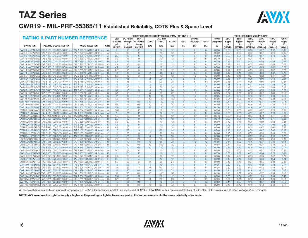
TAZ SeriesCWR19 - MIL-PRF-55365/11 Established Reliability, COTS-Plus & Space Level
Parametric Specifications by Rating per MIL-PRF-55365/11 Typical RMS Ripple Data by RatingCap DC Rated ESR DCL max DF Max Power 25ºC 85ºC 125ºC 25ºC 85ºC 125ºC
@ 120Hz Voltage @ 100kHz +25ºC +85ºC +125ºC +25ºC +(85/125)ºC -55ºC Dissipation Ripple Ripple Ripple Ripple Ripple Ripple
CWR19 P/N AVX MIL & COTS-Plus P/N AVX SRC9000 P/N CaseμF V Ohms
(μA) (μA) (μA) (%) (%) (%) WA A A V V V
@ 25ºC @ +85ºC @ +25ºC (100kHz) (100kHz) (100kHz) (100kHz) (100kHz) (100kHz)CWR19C^335*@A+� TAZ A 335 * 004 C � # @ 0 ^ ++ TAZ A 335 * 004 C � L @ 9 ^ ++ A 3.3 4 12 1 10 12 6 8 8 0.050 0.06 0.06 0.03 0.77 0.70 0.31CWR19C^475*@A+� TAZ A 475 * 004 C � # @ 0 ^ ++ TAZ A 475 * 004 C � L @ 9 ^ ++ A 4.7 4 12 1 10 12 6 8 8 0.050 0.06 0.06 0.03 0.77 0.70 0.31CWR19C^685*@A+� TAZ A 685 * 004 C � # @ 0 ^ ++ TAZ A 685 * 004 C � L @ 9 ^ ++ A 6.8 4 12 1 10 12 6 8 8 0.050 0.06 0.06 0.03 0.77 0.70 0.31CWR19C^106*@B+� TAZ B 106 * 004 C � # @ 0 ^ ++ TAZ B 106 * 004 C � L @ 9 ^ ++ B 10 4 8 1 10 12 8 10 10 0.070 0.09 0.08 0.04 0.75 0.67 0.30CWR19C^156*@B+� TAZ B 156 * 004 C � # @ 0 ^ ++ TAZ B 156 * 004 C � L @ 9 ^ ++ B 15 4 8 1 10 12 8 10 10 0.070 0.09 0.08 0.04 0.75 0.67 0.30CWR19C^226*@B+� TAZ B 226 * 004 C � # @ 0 ^ ++ TAZ B 226 * 004 C � L @ 9 ^ ++ B 22 4 8 1 10 12 8 10 10 0.070 0.09 0.08 0.04 0.75 0.67 0.30CWR19C^226*@D+� TAZ D 226 * 004 C � # @ 0 ^ ++ TAZ D 226 * 004 C � L @ 9 ^ ++ D 22 4 4 1 10 12 8 10 12 0.080 0.14 0.13 0.06 0.57 0.51 0.23CWR19C^336*@D+� TAZ D 336 * 004 C � # @ 0 ^ ++ TAZ D 336 * 004 C � L @ 9 ^ ++ D 33 4 4 2 20 24 8 10 12 0.080 0.14 0.13 0.06 0.57 0.51 0.23CWR19C^336*@E+� TAZ E 336 * 004 C � # @ 0 ^ ++ TAZ E 336 * 004 C � L @ 9 ^ ++ E 33 4 3 2 20 24 8 10 12 0.090 0.17 0.16 0.07 0.52 0.47 0.21CWR19C^476*@E+� TAZ E 476 * 004 C � # @ 0 ^ ++ TAZ E 476 * 004 C � L @ 9 ^ ++ E 47 4 3 2 20 24 8 10 12 0.090 0.17 0.16 0.07 0.52 0.47 0.21CWR19C^686*@E+� TAZ E 686 * 004 C � # @ 0 ^ ++ TAZ E 686 * 004 C � L @ 9 ^ ++ E 68 4 3 3 30 36 8 10 12 0.090 0.17 0.16 0.07 0.52 0.47 0.21CWR19C^107*@F+� TAZ F 107 * 004 C � # @ 0 ^ ++ TAZ F 107 * 004 C � L @ 9 ^ ++ F 100 4 2 4 40 48 10 12 12 0.100 0.22 0.20 0.09 0.45 0.40 0.18CWR19C^157*@G+� TAZ G 157 * 004 C � # @ 0 ^ ++ TAZ G 157 * 004 C � L @ 9 ^ ++ G 150 4 1 6 60 72 10 12 12 0.125 0.35 0.32 0.14 0.35 0.32 0.14CWR19C^227*@H+� TAZ H 227 * 004 C � # @ 0 ^ ++ TAZ H 227 * 004 C � L @ 9 ^ ++ H 220 4 1 8 80 96 10 12 12 0.150 0.39 0.35 0.15 0.39 0.35 0.15CWR19C^337*@H+� TAZ H 337 * 004 C � # @ 0 ^ ++ TAZ H 337 * 004 C � L @ 9 ^ ++ H 330 4 0.9 10 100 120 10 12 12 0.150 0.41 0.37 0.16 0.37 0.33 0.15CWR19D^335*@A+� TAZ A 335 * 006 C � # @ 0 ^ ++ TAZ A 335 * 006 C � L @ 9 ^ ++ A 3.3 6 12 1 10 12 6 8 8 0.050 0.06 0.06 0.03 0.77 0.70 0.31CWR19D^475*@A+� TAZ A 475 * 006 C � # @ 0 ^ ++ TAZ A 475 * 006 C � L @ 9 ^ ++ A 4.7 6 12 1 10 12 6 8 8 0.050 0.06 0.06 0.03 0.77 0.70 0.31CWR19D^685*@B+� TAZ B 685 * 006 C � # @ 0 ^ ++ TAZ B 685 * 006 C � L @ 9 ^ ++ B 6.8 6 8 1 10 12 6 8 8 0.070 0.09 0.08 0.04 0.75 0.67 0.30CWR19D^106*@B+� TAZ B 106 * 006 C � # @ 0 ^ ++ TAZ B 106 * 006 C � L @ 9 ^ ++ B 10 6 8 1 10 12 6 8 8 0.070 0.09 0.08 0.04 0.75 0.67 0.30CWR19D^156*@B+� TAZ B 156 * 006 C � # @ 0 ^ ++ TAZ B 156 * 006 C � L @ 9 ^ ++ B 15 6 8 1 10 12 8 10 10 0.070 0.09 0.08 0.04 0.75 0.67 0.30CWR19D^156*@D+� TAZ D 156 * 006 C � # @ 0 ^ ++ TAZ D 156 * 006 C � L @ 9 ^ ++ D 15 6 5 1 10 12 8 10 12 0.080 0.13 0.11 0.05 0.63 0.57 0.25CWR19D^226*@D+� TAZ D 226 * 006 C � # @ 0 ^ ++ TAZ D 226 * 006 C � L @ 9 ^ ++ D 22 6 5 1 10 12 6 8 8 0.080 0.13 0.11 0.05 0.63 0.57 0.25CWR19D^156*@E+� TAZ E 156 * 006 C � # @ 0 ^ ++ TAZ E 156 * 006 C � L @ 9 ^ ++ E 15 6 3 1 10 12 8 10 12 0.090 0.17 0.16 0.07 0.52 0.47 0.21CWR19D^226*@E+� TAZ E 226 * 006 C � # @ 0 ^ ++ TAZ E 226 * 006 C � L @ 9 ^ ++ E 22 6 3.5 2 20 24 8 10 12 0.090 0.16 0.14 0.06 0.56 0.51 0.22CWR19D^336*@E+� TAZ E 336 * 006 C � # @ 0 ^ ++ TAZ E 336 * 006 C � L @ 9 ^ ++ E 33 6 3.5 2 20 24 6 8 8 0.090 0.16 0.14 0.06 0.56 0.51 0.22CWR19D^476*@F+� TAZ F 476 * 006 C � # @ 0 ^ ++ TAZ F 476 * 006 C � L @ 9 ^ ++ F 47 6 3.5 3 30 36 8 10 12 0.100 0.17 0.15 0.07 0.59 0.53 0.24CWR19D^686*@F+� TAZ F 686 * 006 C � # @ 0 ^ ++ TAZ F 686 * 006 C � L @ 9 ^ ++ F 68 6 1.5 4 40 48 10 12 12 0.100 0.26 0.23 0.10 0.39 0.35 0.15CWR19D^686*@G+� TAZ G 686 * 006 C � # @ 0 ^ ++ TAZ G 686 * 006 C � L @ 9 ^ ++ G 68 6 1 4 40 48 10 12 12 0.125 0.35 0.32 0.14 0.35 0.32 0.14CWR19D^107*@G+� TAZ G 107 * 006 C � # @ 0 ^ ++ TAZ G 107 * 006 C � L @ 9 ^ ++ G 100 6 1.1 6 60 72 10 12 12 0.125 0.34 0.30 0.13 0.37 0.33 0.15CWR19D^157*@G+� TAZ G 157 * 006 C � # @ 0 ^ ++ TAZ G 157 * 006 C � L @ 9 ^ ++ G 150 6 1.1 10 100 120 10 12 12 0.125 0.34 0.30 0.13 0.37 0.33 0.15CWR19D^227*@H+� TAZ H 227 * 006 C � # @ 0 ^ ++ TAZ H 227 * 006 C � L @ 9 ^ ++ H 220 6 0.9 10 100 120 10 12 12 0.150 0.41 0.37 0.16 0.37 0.33 0.15CWR19D^337*@H+� TAZ H 337 * 006 C � # @ 0 ^ ++ TAZ H 337 * 006 C � L @ 9 ^ ++ H 330 6 0.9 20 200 240 10 12 12 0.150 0.41 0.37 0.16 0.37 0.33 0.15CWR19F^225*@A+� TAZ A 225 * 010 C � # @ 0 ^ ++ TAZ A 225 * 010 C � L @ 9 ^ ++ A 2.2 10 12 1 10 12 6 8 8 0.050 0.06 0.06 0.03 0.77 0.70 0.31CWR19F^335*@A+� TAZ A 335 * 010 C � # @ 0 ^ ++ TAZ A 335 * 010 C � L @ 9 ^ ++ A 3.3 10 12 1 10 12 6 8 8 0.050 0.06 0.06 0.03 0.77 0.70 0.31CWR19F^475*@B+� TAZ B 475 * 010 C � # @ 0 ^ ++ TAZ B 475 * 010 C � L @ 9 ^ ++ B 4.7 10 8 1 10 12 6 8 8 0.070 0.09 0.08 0.04 0.75 0.67 0.30CWR19F^685*@B+� TAZ B 685 * 010 C � # @ 0 ^ ++ TAZ B 685 * 010 C � L @ 9 ^ ++ B 6.8 10 8 1 10 12 6 8 8 0.070 0.09 0.08 0.04 0.75 0.67 0.30CWR19F^106*@B+� TAZ B 106 * 010 C � # @ 0 ^ ++ TAZ B 106 * 010 C � L @ 9 ^ ++ B 10 10 8 1 10 12 8 10 10 0.070 0.09 0.08 0.04 0.75 0.67 0.30CWR19F^475*@C+� TAZ C 475 * 010 C � # @ 0 ^ ++ TAZ C 475 * 010 C � L @ 9 ^ ++ C 4.7 10 5.5 1 10 12 6 8 8 0.075 0.12 0.11 0.05 0.64 0.58 0.26CWR19F^685*@C+� TAZ C 685 * 010 C � # @ 0 ^ ++ TAZ C 685 * 010 C � L @ 9 ^ ++ C 6.8 10 5.5 1 10 12 6 8 8 0.075 0.12 0.11 0.05 0.64 0.58 0.26CWR19F^106*@C+� TAZ C 106 * 010 C � # @ 0 ^ ++ TAZ C 106 * 010 C � L @ 9 ^ ++ C 10 10 5.5 1 10 12 6 8 8 0.075 0.12 0.11 0.05 0.64 0.58 0.26CWR19F^685*@D+� TAZ D 685 * 010 C � # @ 0 ^ ++ TAZ D 685 * 010 C � L @ 9 ^ ++ D 6.8 10 5 1 10 12 6 8 8 0.080 0.13 0.11 0.05 0.63 0.57 0.25CWR19F^106*@D+� TAZ D 106 * 010 C � # @ 0 ^ ++ TAZ D 106 * 010 C � L @ 9 ^ ++ D 10 10 4 1 10 12 6 8 8 0.080 0.14 0.13 0.06 0.57 0.51 0.23CWR19F^156*@D+� TAZ D 156 * 010 C � # @ 0 ^ ++ TAZ D 156 * 010 C � L @ 9 ^ ++ D 15 10 5 2 20 24 6 8 8 0.080 0.13 0.11 0.05 0.63 0.57 0.25CWR19F^106*@E+� TAZ E 106 * 010 C � # @ 0 ^ ++ TAZ E 106 * 010 C � L @ 9 ^ ++ E 10 10 3.5 1 10 12 6 8 8 0.090 0.16 0.14 0.06 0.56 0.51 0.22CWR19F^156*@E+� TAZ E 156 * 010 C � # @ 0 ^ ++ TAZ E 156 * 010 C � L @ 9 ^ ++ E 15 10 3 2 20 24 8 10 10 0.090 0.17 0.16 0.07 0.52 0.47 0.21CWR19F^226*@E+� TAZ E 226 * 010 C � # @ 0 ^ ++ TAZ E 226 * 010 C � L @ 9 ^ ++ E 22 10 2 3 30 36 8 10 10 0.090 0.21 0.19 0.08 0.42 0.38 0.17CWR19F^336*@F+� TAZ F 336 * 010 C � # @ 0 ^ ++ TAZ F 336 * 010 C � L @ 9 ^ ++ F 33 10 1.5 3 30 36 8 10 10 0.100 0.26 0.23 0.10 0.39 0.35 0.15CWR19F^476*@F+� TAZ F 476 * 010 C � # @ 0 ^ ++ TAZ F 476 * 010 C � L @ 9 ^ ++ F 47 10 1.5 4 40 48 10 12 12 0.100 0.26 0.23 0.10 0.39 0.35 0.15CWR19F^476*@G+� TAZ G 476 * 010 C � # @ 0 ^ ++ TAZ G 476 * 010 C � L @ 9 ^ ++ G 47 10 1 4 40 48 10 12 12 0.125 0.35 0.32 0.14 0.35 0.32 0.14CWR19F^686*@G+� TAZ G 686 * 010 C � # @ 0 ^ ++ TAZ G 686 * 010 C � L @ 9 ^ ++ G 68 10 1.1 6 60 72 10 12 12 0.125 0.34 0.30 0.13 0.37 0.33 0.15CWR19F^107*@G+� TAZ G 107 * 010 C � # @ 0 ^ ++ TAZ G 107 * 010 C � L @ 9 ^ ++ G 100 10 1.1 10 100 120 10 12 12 0.125 0.34 0.30 0.13 0.37 0.33 0.15CWR19F^107*@H+� TAZ H 107 * 010 C � # @ 0 ^ ++ TAZ H 107 * 010 C � L @ 9 ^ ++ H 100 10 0.9 10 100 120 10 12 12 0.150 0.41 0.37 0.16 0.37 0.33 0.15CWR19F^157*@H+� TAZ H 157 * 010 C � # @ 0 ^ ++ TAZ H 157 * 010 C � L @ 9 ^ ++ H 150 10 0.9 15 150 180 10 12 12 0.150 0.41 0.37 0.16 0.37 0.33 0.15CWR19F^227*@H+� TAZ H 227 * 010 C � # @ 0 ^ ++ TAZ H 227 * 010 C � L @ 9 ^ ++ H 220 10 0.9 20 200 240 10 12 12 0.150 0.41 0.37 0.16 0.37 0.33 0.15CWR19F^157*@X+� TAZ X 157 * 010 C � # @ 0 ^ ++ TAZ X 157 * 010 C � L @ 9 ^ ++ X 150 10 0.9 15 150 180 10 12 12 0.200 0.47 0.42 0.19 0.42 0.38 0.17
RATING & PART NUMBER REFERENCE
All technical data relates to an ambient temperature of +25°C. Capacitance and DF are measured at 120Hz, 0.5V RMS with a maximum DC bias of 2.2 volts. DCL is measured at rated voltage after 5 minutes.
NOTE: AVX reserves the right to supply a higher voltage rating or tighter tolerance part in the same case size, to the same reliability standards.
16 111416
TAZ SeriesCWR19 - MIL-PRF-55365/11 Established Reliability, COTS-Plus & Space Level
Parametric Specifications by Rating per MIL-PRF-55365/11 Typical RMS Ripple Data by RatingCap DC Rated ESR DCL max DF Max Power 25ºC 85ºC 125ºC 25ºC 85ºC 125ºC
@ 120Hz Voltage @ 100kHz +25ºC +85ºC +125ºC +25ºC +(85/125)ºC -55ºC Dissipation Ripple Ripple Ripple Ripple Ripple Ripple
CWR19 P/N AVX MIL & COTS-Plus P/N AVX SRC9000 P/N CaseμF V Ohms
(μA) (μA) (μA) (%) (%) (%) WA A A V V V
@ 25ºC @ +85ºC @ +25ºC (100kHz) (100kHz) (100kHz) (100kHz) (100kHz) (100kHz)CWR19H^105*@A+� TAZ A 105 * 015 C � # @ 0 ^ ++ TAZ A 105 * 015 C � L @ 9 ^ ++ A 1 15 15 1 10 12 6 8 8 0.050 0.06 0.05 0.02 0.87 0.78 0.35CWR19H^155*@A+� TAZ A 155 * 015 C � # @ 0 ^ ++ TAZ A 155 * 015 C � L @ 9 ^ ++ A 1.5 15 15 1 10 12 6 8 8 0.050 0.06 0.05 0.02 0.87 0.78 0.35CWR19H^225*@A+� TAZ A 225 * 015 C � # @ 0 ^ ++ TAZ A 225 * 015 C � L @ 9 ^ ++ A 2.2 15 15 1 10 12 6 8 8 0.050 0.06 0.05 0.02 0.87 0.78 0.35CWR19H^335*@B+� TAZ B 335 * 015 C � # @ 0 ^ ++ TAZ B 335 * 015 C � L @ 9 ^ ++ B 3.3 15 9 1 10 12 6 8 8 0.070 0.09 0.08 0.04 0.79 0.71 0.32CWR19H^475*@B+� TAZ B 475 * 015 C � # @ 0 ^ ++ TAZ B 475 * 015 C � L @ 9 ^ ++ B 4.7 15 5 1 10 12 6 8 8 0.070 0.12 0.11 0.05 0.59 0.53 0.24CWR19H^475*@C+� TAZ C 475 * 015 C � # @ 0 ^ ++ TAZ C 475 * 015 C � L @ 9 ^ ++ C 4.7 15 5.5 1 10 12 6 8 8 0.075 0.12 0.11 0.05 0.64 0.58 0.26CWR19H^475*@D+� TAZ D 475 * 015 C � # @ 0 ^ ++ TAZ D 475 * 015 C � L @ 9 ^ ++ D 4.7 15 6 1 10 12 6 8 8 0.080 0.12 0.10 0.05 0.69 0.62 0.28CWR19H^685*@D+� TAZ D 685 * 015 C � # @ 0 ^ ++ TAZ D 685 * 015 C � L @ 9 ^ ++ D 6.8 15 6 1 10 12 6 8 8 0.080 0.12 0.10 0.05 0.69 0.62 0.28CWR19H^106*@D+� TAZ D 106 * 015 C � # @ 0 ^ ++ TAZ D 106 * 015 C � L @ 9 ^ ++ D 10 15 6 2 20 24 6 8 8 0.080 0.12 0.10 0.05 0.69 0.62 0.28CWR19H^685*@E+� TAZ E 685 * 015 C � # @ 0 ^ ++ TAZ E 685 * 015 C � L @ 9 ^ ++ E 6.8 15 3 1 10 12 8 10 12 0.090 0.17 0.16 0.07 0.52 0.47 0.21CWR19H^106*@E+� TAZ E 106 * 015 C � # @ 0 ^ ++ TAZ E 106 * 015 C � L @ 9 ^ ++ E 10 15 4 2 20 24 6 8 8 0.090 0.15 0.14 0.06 0.60 0.54 0.24CWR19H^156*@E+� TAZ E 156 * 015 C � # @ 0 ^ ++ TAZ E 156 * 015 C � L @ 9 ^ ++ E 15 15 4 2 20 24 6 8 8 0.090 0.15 0.14 0.06 0.60 0.54 0.24CWR19H^156*@F+� TAZ F 156 * 015 C � # @ 0 ^ ++ TAZ F 156 * 015 C � L @ 9 ^ ++ F 15 15 3 2 20 24 8 10 10 0.100 0.18 0.16 0.07 0.55 0.49 0.22CWR19H^226*@F+� TAZ F 226 * 015 C � # @ 0 ^ ++ TAZ F 226 * 015 C � L @ 9 ^ ++ F 22 15 3 3 30 36 8 10 10 0.100 0.18 0.16 0.07 0.55 0.49 0.22CWR19H^336*@F+� TAZ F 336 * 015 C � # @ 0 ^ ++ TAZ F 336 * 015 C � L @ 9 ^ ++ F 33 15 3 5 50 60 6 8 8 0.100 0.18 0.16 0.07 0.55 0.49 0.22CWR19H^336*@G+� TAZ G 336 * 015 C � # @ 0 ^ ++ TAZ G 336 * 015 C � L @ 9 ^ ++ G 33 15 1.1 6 60 72 8 10 10 0.125 0.34 0.30 0.13 0.37 0.33 0.15CWR19H^476*@G+� TAZ G 476 * 015 C � # @ 0 ^ ++ TAZ G 476 * 015 C � L @ 9 ^ ++ G 47 15 1.1 10 100 120 8 10 10 0.125 0.34 0.30 0.13 0.37 0.33 0.15CWR19H^686*@G+� TAZ G 686 * 015 C � # @ 0 ^ ++ TAZ G 686 * 015 C � L @ 9 ^ ++ G 68 15 1.1 10 100 120 8 10 10 0.125 0.34 0.30 0.13 0.37 0.33 0.15CWR19H^476*@H+� TAZ H 476 * 015 C � # @ 0 ^ ++ TAZ H 476 * 015 C � L @ 9 ^ ++ H 47 15 0.9 10 100 120 8 10 10 0.150 0.41 0.37 0.16 0.37 0.33 0.15CWR19H^686*@H+� TAZ H 686 * 015 C � # @ 0 ^ ++ TAZ H 686 * 015 C � L @ 9 ^ ++ H 68 15 0.9 10 100 120 8 10 10 0.150 0.41 0.37 0.16 0.37 0.33 0.15CWR19H^107*@H+� TAZ H 107 * 015 C � # @ 0 ^ ++ TAZ H 107 * 015 C � L @ 9 ^ ++ H 100 15 0.9 15 150 180 10 12 12 0.150 0.41 0.37 0.16 0.37 0.33 0.15CWR19J^684*@A+� TAZ A 684 * 020 C � # @ 0 ^ ++ TAZ A 684 * 020 C � L @ 9 ^ ++ A 0.68 20 15 1 10 12 6 8 8 0.050 0.06 0.05 0.02 0.87 0.78 0.35CWR19J^105*@A+� TAZ A 105 * 020 C � # @ 0 ^ ++ TAZ A 105 * 020 C � L @ 9 ^ ++ A 1 20 15 1 10 12 6 8 8 0.050 0.06 0.05 0.02 0.87 0.78 0.35CWR19J^155*@B+� TAZ B 155 * 020 C � # @ 0 ^++ TAZ B 155 * 020 C � L @ 9 ^++ B 1.5 20 9 1 10 12 6 8 8 0.070 0.09 0.08 0.04 0.79 0.71 0.32CWR19J^225*@B+� TAZ B 225 * 020 C � # @ 0 ^ ++ TAZ B 225 * 020 C � L @ 9 ^ ++ B 2.2 20 9 1 10 12 6 8 8 0.070 0.09 0.08 0.04 0.79 0.71 0.32CWR19J^335*@D+� TAZ D 335 * 020 C � # @ 0 ^ ++ TAZ D 335 * 020 C � L @ 9 ^ ++ D 3.3 20 6 1 10 12 6 8 8 0.080 0.12 0.10 0.05 0.69 0.62 0.28CWR19J^475*@E+� TAZ E 475 * 020 C � # @ 0 ^ ++ TAZ E 475 * 020 C � L @ 9 ^ ++ E 4.7 20 6 1 10 12 6 8 8 0.090 0.12 0.11 0.05 0.73 0.66 0.29CWR19J^685*@E+� TAZ E 685 * 020 C � # @ 0 ^ ++ TAZ E 685 * 020 C � L @ 9 ^ ++ E 6.8 20 5 2 20 24 6 8 8 0.090 0.13 0.12 0.05 0.67 0.60 0.27CWR19J^106*@E+� TAZ E 106 * 020 C � # @ 0 ^ ++ TAZ E 106 * 020 C � L @ 9 ^ ++ E 10 20 5 2 20 24 6 8 8 0.090 0.13 0.12 0.05 0.67 0.60 0.27CWR19J^106*@F+� TAZ F 106 * 020 C � # @ 0 ^ ++ TAZ F 106 * 020 C � L @ 9 ^ ++ F 10 20 3 2 20 24 6 8 8 0.100 0.18 0.16 0.07 0.55 0.49 0.22CWR19J^156*@F+� TAZ F 156 * 020 C � # @ 0 ^ ++ TAZ F 156 * 020 C � L @ 9 ^ ++ F 15 20 3 3 30 36 6 8 8 0.100 0.18 0.16 0.07 0.55 0.49 0.22CWR19J^226*@G+� TAZ G 226 * 020 C � # @ 0 ^ ++ TAZ G 226 * 020 C � L @ 9 ^ ++ G 22 20 2.5 4 40 48 6 8 8 0.125 0.22 0.20 0.09 0.56 0.50 0.22CWR19J^336*@H+� TAZ H 336 * 020 C � # @ 0 ^ ++ TAZ H 336 * 020 C � L @ 9 ^ ++ H 33 20 0.9 6 60 72 8 10 10 0.150 0.41 0.37 0.16 0.37 0.33 0.15CWR19J^476*@H+� TAZ H 476 * 020 C � # @ 0 ^ ++ TAZ H 476 * 020 C � L @ 9 ^ ++ H 47 20 0.9 10 100 120 8 10 10 0.150 0.41 0.37 0.16 0.37 0.33 0.15CWR19J^476*@X+� TAZ X 476 * 020 C � # @ 0 ^ ++ TAZ X 476 * 020 C � L @ 9 ^ ++ X 47 20 0.9 10 100 120 8 10 10 0.200 0.47 0.42 0.19 0.42 0.38 0.17CWR19K^474*@A+� TAZ A 474 * 025 C � # @ 0 ^ ++ TAZ A 474 * 025 C � L @ 9 ^ ++ A 0.47 25 15 1 10 12 6 8 8 0.050 0.06 0.05 0.02 0.87 0.78 0.35CWR19K^105*@B+� TAZ B 105 * 025 C � # @ 0 ^ ++ TAZ B 105 * 025 C � L @ 9 ^ ++ B 1 25 10 1 10 12 6 8 8 0.070 0.08 0.08 0.03 0.84 0.75 0.33CWR19K^225*@D+� TAZ D 225 * 025 C � # @ 0 ^ ++ TAZ D 225 * 025 C � L @ 9 ^ ++ D 2.2 25 6 1 10 12 6 8 8 0.080 0.12 0.10 0.05 0.69 0.62 0.28CWR19K^335*@E+� TAZ E 335 * 025 C � # @ 0 ^ ++ TAZ E 335 * 025 C � L @ 9 ^ ++ E 3.3 25 4 1 10 12 6 8 8 0.090 0.15 0.14 0.06 0.60 0.54 0.24CWR19K^685*@F+� TAZ F 685 * 025 C � # @ 0 ^ ++ TAZ F 685 * 025 C � L @ 9 ^ ++ F 6.8 25 3 2 20 24 6 8 8 0.100 0.18 0.16 0.07 0.55 0.49 0.22CWR19K^156*@G+� TAZ G 156 * 025 C � # @ 0 ^ ++ TAZ G 156 * 025 C � L @ 9 ^ ++ G 15 25 1.4 4 40 48 6 8 8 0.125 0.30 0.27 0.12 0.42 0.38 0.17CWR19K^226*@G+� TAZ G 226 * 025 C � # @ 0 ^ ++ TAZ G 226 * 025 C � L @ 9 ^ ++ G 22 25 1.4 6 60 72 6 8 8 0.125 0.30 0.27 0.12 0.42 0.38 0.17CWR19K^226*@H+� TAZ H 226 * 025 C � # @ 0 ^ ++ TAZ H 226 * 025 C � L @ 9 ^ ++ H 22 25 0.9 6 60 72 6 8 8 0.150 0.41 0.37 0.16 0.37 0.33 0.15CWR19K^336*@H+� TAZ H 336 * 025 C � # @ 0 ^ ++ TAZ H 336 * 025 C � L @ 9 ^ ++ H 33 25 0.9 10 100 120 8 10 10 0.150 0.41 0.37 0.16 0.37 0.33 0.15CWR19M^334*@A+� TAZ A 334 * 035 C � # @ 0 ^ ++ TAZ A 334 * 035 C � L @ 9 ^ ++ A 0.33 35 22 1 10 12 6 8 8 0.050 0.05 0.04 0.02 1.05 0.94 0.42CWR19M^685*@G+� TAZ G 685 * 035 C � # @ 0 ^ ++ TAZ G 685 * 035 C � L @ 9 ^ ++ G 6.8 35 1.5 3 30 36 6 8 8 0.125 0.29 0.26 0.12 0.43 0.39 0.17CWR19M^106*@H+� TAZ H 106 * 035 C � # @ 0 ^ ++ TAZ H 106 * 035 C � L @ 9 ^ ++ H 10 35 0.9 4 40 48 8 10 10 0.150 0.41 0.37 0.16 0.37 0.33 0.15CWR19M^156*@X+� TAZ X 156 * 035 C � # @ 0 ^ ++ TAZ X 156 * 035 C � L @ 9 ^ ++ X 15 35 0.9 6 60 72 6 8 8 0.200 0.47 0.42 0.19 0.42 0.38 0.17
RATING & PART NUMBER REFERENCE
All technical data relates to an ambient temperature of +25°C. Capacitance and DF are measured at 120Hz, 0.5V RMS with a maximum DC bias of 2.2 volts. DCL is measured at rated voltage after 5 minutes.
NOTE: AVX reserves the right to supply a higher voltage rating or tighter tolerance part in the same case size, to the same reliability standards.

17111416
A low ESR version of CWR09 and CWR19 thatis fully qualified to MIL-PRF-55365/11, theCWR29 series represents the most flexible of sur-face mount form factors and the optimum powerhanding for all filtering applications. It is offered innine case sizes (the original A through H ofCWR09 and adding the new X case size).
The molded body / compliant termination con-struction ensures no TCE mismatch with any sub-strate. This construction is compatible with a widerange of SMT board assembly processes includ-ing wave or reflow solder, conductive epoxy orcompression bonding techniques. The parts alsocarry full polarity and capacitance / voltage mark-ing.
The five smaller cases are characterized by theirlow profile construction, with the A case being theworld’s smallest molded military tantalum chip.
The series is qualified to MIL-PRF-55365 Weibull“B”, “C”, “D” and “T” levels, with all surge options(“A”, “B” & “C”) available.
For Space Level applications, AVX SRC 9000qualification is recommended (see ratings table forpart number availability).
There are four termination finishes available:solder plated, fused solder plated, hot solderdipped and gold plated (these are “H”, “K”, “C”and “B” termination, respectively, per MIL-PRF-55365). In addition, the molding compound hasbeen selected to meet the requirements ofUL94V-0 (Flame Retardancy) and outgassingrequirements of ASTM E-595.
For moisture sensitivity levels please refer to theHigh Reliability Tantalum MSL section located inthe back of the High Reliability Tantalum Catalog.
MARKING(White marking on black body)
Polarity Stripe (+)
Capacitance CodeRated Voltage
TAZ SeriesCWR29 - MIL-PRF-55365/11 Established Reliability, COTS-Plus & Space Level
Capacitance Rated voltage DC (VR) at 85ºC μF Code 4V (C) 6V (D) 10V (F) 15V (H) 20V (J) 25V (K) 35V (M) 50V (N) 0.10 104 A 0.15 154 A 0.22 224 A B 0.33 334 A A B 0.47 474 A A B C 0.68 684 A A/B B C D 1.0 105 A A A/B B/C D E 1.5 155 A A/B B/C D E F 2.2 225 A A/B A/C B/D D/E F 3.3 335 A A/B A/C B/D D/E E F G 4.7 475 A/B A/C B/C/D B/C/D/E E F G H 6.8 685 A/C B/D B/C/D/E D/E E/F F/G G/H 10 106 B/D B/E B/C/D/E D/E/F E/F G H 15 156 B/E B/D/E D/E/F E/F F/G G/H X 22 226 B/D D/E/F E F/G G/H G/H 33 336 D/E/F E F/G F/G/H H H 47 476 E F/G F/G/H G/H H/X 68 686 E/G F/G/H G G/H 100 107 F/H G G/H H 150 157 G G H/X 220 227 H H H 330 337 H H
CWR29-MIL-PRF 55365/11CAPACITANCE AND RATED VOLTAGE, VR (VOLTAGE CODE) RANGE (LETTER DENOTES CASE SIZE)
CASE DIMENSIONS: millimeters (inches)
Case Length (L) Width (W) Height (H) Term. Length (A)
TypicalCode ±0.38 (0.015) ±0.38 (0.015) ±0.38 (0.015)
Term. Width (W1) +0.25/-0.13 S min Weight (g) (+0.010/-0.005)
A 2.54 (0.100) 1.27 (0.050) 1.27 (0.050)
1.27±0.13 0.76 (0.030) 0.38 (0.015) 0.016 (0.050±0.005)
B 3.81 (0.150) 1.27 (0.050) 1.27 (0.050)
1.27±0.13 0.76 (0.030) 1.65 (0.065) 0.025 (0.050±0.005)
C 5.08 (0.200) 1.27 (0.050) 1.27 (0.050) 1.27±0.13
0.76 (0.030) 2.92 (0.115) 0.035 (0.050±0.005)
D 3.81 (0.150) 2.54 (0.100) 1.27 (0.050) 2.41+0.13/-0.25
0.76 (0.030) 1.65 (0.065) 0.045 (0.095+0.005/-0.010)
E 5.08 (0.200) 2.54 (0.100) 1.27 (0.050)
2.41+0.13/-0.25 0.76 (0.030) 2.92 (0.115) 0.065 (0.095+0.005/-0.010)
F 5.59 (0.220) 3.43 (0.135) 1.78 (0.070)
3.30±0.13 0.76 (0.030) 3.43 (0.135) 0.125 (0.130±0.005)
G 6.73 (0.265) 2.79 (0.110) 2.79 (0.110)
2.67±0.13 1.27 (0.050) 3.56 (0.140) 0.205 (0.105±0.005)
H 7.24 (0.285) 3.81 (0.150) 2.79 (0.110)
3.68+0.13/-0.51 1.27 (0.050) 4.06 (0.160) 0.335 (0.145+0.005/-0.020)
X 6.93 (0.273) 5.41 (0.213) 2.74 (0.108)
3.05±0.13 1.19 (0.047) N/A 0.420 (0.120±0.005)

18 111416
Technical Data: Unless otherwise specified, all technical data relate to an ambient temperature of 25°CCapacitance Range: 0.10 μF to 330 μFCapacitance Tolerance: ±5%; ±10%; ±20%Rated Voltage (VR) � 85°C: 4 6 10 15 20 25 35 50Category Voltage (VC) � 125°C: 2.7 4 6.7 10 13.3 16.7 23.3 33.3Surge Voltage (VS) � 85°C: 5.3 8 13.3 20 26.7 33.3 46.7 66.7Surge Voltage (VS) � 125°C: 3.5 5.3 8.7 13.3 17.8 22.2 31.1 44.5Temperature Range: -55°C to +125°C
TECHNICAL SPECIFICATIONS
TAZ SeriesCWR29 - MIL-PRF-55365/11 Established Reliability, COTS-Plus & Space Level
CWR29 P/N CROSS REFERENCE:
SPACE LEVEL OPTIONS TO SRC9000*:
*
CapacitanceTolerance
M = ±20% K = ±10% J = ±5%
�
Packaging B = Bulk R = 7" T&R S = 13" T&RW = Waffle
See page 8for additionalpackagingoptions.
++
Surge TestOption
00 = None23 = 10 Cycles, +25ºC24 = 10 Cycles,
-55ºC & +85ºC45 = 10 cycles,
-55ºC & +85ºCbefore Weibull
TAZ
Type
H
CaseSize
C
Standard orLow ESR
RangeC = Std ESRL = Low ESR
#
Inspection LevelS = Std.
ConformanceL = Group A
HOW TO ORDERCOTS-PLUS & MIL QPL (CWR29):
006
VoltageCode
004 = 4Vdc006 = 6Vdc010 = 10Vdc015 = 15Vdc020 = 20Vdc025 = 25Vdc035 = 35Vdc050 = 50Vdc
227
CapacitanceCode
pF code: 1st two digits
representsignificant figures 3rd
digit representsmultiplier
(number ofzeros to follow)
@
Reliability GradeWeibull: B = 0.1%/1000 hrs.
90% conf.C = 0.01%/1000 hrs.
90% conf.D = 0.001%/1000 hrs.
90% conf.Z = Non-ER
^
Termination FinishH = Solder Plated0 = Fused Solder
Plated8 = Hot Solder
Dipped9 = Gold Plated7 = Matte Sn
(COTS-Plusonly)
M = MIL (JAN)CWR29
9 = SRC9000
*
CapacitanceTolerance
M = ±20% K = ±10% J = ±5%
�
Packaging B = Bulk R = 7" T&R S = 13" T&RW = Waffle
See page 8for additionalpackagingoptions.
++
Surge TestOption
45 = 10 cycles, -55ºC & +85ºCbefore Weibull
TAZ
Type
H
CaseSize
C
Standard orLow ESR
RangeC = Std ESRL = Low ESR
L
Inspection LevelL = Group A
006
VoltageCode
004 = 4Vdc006 = 6Vdc010 = 10Vdc015 = 15Vdc020 = 20Vdc025 = 25Vdc035 = 35Vdc050 = 50Vdc
227
CapacitanceCode
pF code: 1st two digits
representsignificant figures 3rd
digit representsmultiplier
(number ofzeros to follow)
@
Reliability GradeWeibull: B = 0.1%/1000 hrs.
90% conf.C = 0.01%/1000 hrs.
90% conf.D = 0.001%/1000 hrs.
90% conf.
9
QualificationLevel
9 = SRC9000
^
Termination FinishH = Solder Plated0 = Fused Solder
Plated8 = Hot Solder
Dipped9 = Gold Plated
*
CapacitanceTolerance
M = ±20% K = ±10% J = ±5%
�
Packaging Bulk = Standard \TR = 7" T&R \TR13 = 13" T&R \W = Waffle
See page 8 for additional
packaging op-tions.
+
Surge TestOption
A = 10 cycles, +25°CB = 10 cycles,
-55°C & +85°CC = 10 cycles,
-55°C & +85°C before Weibull
Z = None required
CWR29
Type
D
VoltageCode
C = 4VdcD = 6Vdc F = 10VdcH = 15Vdc J = 20Vdc K = 25VdcM = 35VdcN = 50Vdc
^
TerminationFinish
H = Solder PlatedK = Solder Fused C = Hot Solder
DippedB = Gold Plated
227
CapacitanceCode
pF code: 1st two digits
representsignificant
figures 3rd digitrepresentsmultiplier
(number of zerosto follow)
@
ReliabilityGrade
Weibull: B = 0.1%/1000 hrs.
90% conf.C = 0.01%/1000 hrs.
90% conf.D = 0.001%/1000
hrs. 90% conf.T = T LevelA = Non-ER
*Contact factory for AVX SRC9000 Space Level SCD details.
H
CaseSize
0
QualificationLevel
0 = N/AT = T Level
LEAD-FREE COMPATIBLECOMPONENT
For RoHS compliant products, please select correct termination style.
LEAD-FREE COMPATIBLECOMPONENT
For RoHS compliant products, please select correct termination style.
LEAD-FREE COMPATIBLECOMPONENT
For RoHS compliant products, please select correct termination style.

19111416
TAZ SeriesCWR29 - MIL-PRF-55365/11 Established Reliability, COTS-Plus & Space Level
Parametric Specifications by Rating per MIL-PRF-55365/11 Typical RMS Ripple Data by RatingCap DC Rated ESR DCL max DF Max Power 25ºC 85ºC 125ºC 25ºC 85ºC 125ºC
@ 120Hz Voltage @ 100kHz +25ºC +85ºC +125ºC +25ºC +(85/125)ºC -55ºC Dissipation Ripple Ripple Ripple Ripple Ripple Ripple
CWR29 P/N AVX MIL & COTS-Plus P/N AVX SRC9000 P/N CaseμF V Ohms
(μA) (μA) (μA) (%) (%) (%) WA A A V V V
@ 25ºC @ +85ºC @ +25ºC (100kHz) (100kHz) (100kHz) (100kHz) (100kHz) (100kHz)CWR29C^225*@A+� TAZ A 225 * 004 L � # @ 0 ^ ++ TAZ A 225 * 004 L � L @ 9 ^ ++ A 2.2 4 4 1 10 12 6 8 8 0.050 0.11 0.10 0.04 0.45 0.40 0.18CWR29C^335*@A+� TAZ A 335 * 004 L � # @ 0 ^ ++ TAZ A 335 * 004 L � L @ 9 ^ ++ A 3.3 4 6 1 10 12 6 8 8 0.050 0.09 0.08 0.04 0.55 0.49 0.22CWR29C^475*@A+� TAZ A 475 * 004 L � # @ 0 ^ ++ TAZ A 475 * 004 L � L @ 9 ^ ++ A 4.7 4 6 1 10 12 6 8 8 0.050 0.09 0.08 0.04 0.55 0.49 0.22CWR29C^475*@B+� TAZ B 475 * 004 L � # @ 0 ^ ++ TAZ B 475 * 004 L � L @ 9 ^ ++ B 4.7 4 3.2 1 10 12 6 8 8 0.070 0.15 0.13 0.06 0.47 0.43 0.19CWR29C^685*@A+� TAZ A 685 * 004 L � # @ 0 ^ ++ TAZ A 685 * 004 L � L @ 9 ^ ++ A 6.8 4 6 1 10 12 6 8 8 0.050 0.09 0.08 0.04 0.55 0.49 0.22CWR29C^685*@C+� TAZ C 685 * 004 L � # @ 0 ^ ++ TAZ C 685 * 004 L � L @ 9 ^ ++ C 6.8 4 2.2 1 10 12 6 8 8 0.075 0.18 0.17 0.07 0.41 0.37 0.16CWR29C^106*@B+� TAZ B 106 * 004 L � # @ 0 ^ ++ TAZ B 106 * 004 L � L @ 9 ^ ++ B 10 4 3.2 1 10 12 8 10 10 0.070 0.15 0.13 0.06 0.47 0.43 0.19CWR29C^106*@D+� TAZ D 106 * 004 L � # @ 0 ^ ++ TAZ D 106 * 004 L � L @ 9 ^ ++ D 10 4 1.3 1 10 12 8 8 10 0.080 0.25 0.22 0.10 0.32 0.29 0.13CWR29C^156*@B+� TAZ B 156 * 004 L � # @ 0 ^ ++ TAZ B 156 * 004 L � L @ 9 ^ ++ B 15 4 3.2 1 10 12 8 10 10 0.070 0.15 0.13 0.06 0.47 0.43 0.19CWR29C^156*@E+� TAZ E 156 * 004 L � # @ 0 ^ ++ TAZ E 156 * 004 L � L @ 9 ^ ++ E 15 4 1 1 10 12 8 10 12 0.090 0.30 0.27 0.12 0.30 0.27 0.12CWR29C^226*@B+� TAZ B 226 * 004 L � # @ 0 ^ ++ TAZ B 226 * 004 L � L @ 9 ^ ++ B 22 4 3.2 1 10 12 8 10 10 0.070 0.15 0.13 0.06 0.47 0.43 0.19CWR29C^226*@D+� TAZ D 226 * 004 L � # @ 0 ^ ++ TAZ D 226 * 004 L � L @ 9 ^ ++ D 22 4 1.3 1 10 12 8 10 12 0.080 0.25 0.22 0.10 0.32 0.29 0.13CWR29C^336*@D+� TAZ D 336 * 004 L � # @ 0 ^ ++ TAZ D 336 * 004 L � L @ 9 ^ ++ D 33 4 1.3 2 20 24 8 10 12 0.080 0.25 0.22 0.10 0.32 0.29 0.13CWR29C^336*@E+� TAZ E 336 * 004 L � # @ 0 ^ ++ TAZ E 336 * 004 L � L @ 9 ^ ++ E 33 4 0.9 2 20 24 8 10 12 0.090 0.32 0.28 0.13 0.28 0.26 0.11CWR29C^336*@F+� TAZ F 336 * 004 L � # @ 0 ^ ++ TAZ F 336 * 004 L � L @ 9 ^ ++ F 33 4 0.6 2 20 24 8 10 12 0.100 0.41 0.37 0.16 0.24 0.22 0.10CWR29C^476*@E+� TAZ E 476 * 004 L � # @ 0 ^ ++ TAZ E 476 * 004 L � L @ 9 ^ ++ E 47 4 0.9 2 20 24 8 10 12 0.090 0.32 0.28 0.13 0.28 0.26 0.11CWR29C^686*@E+� TAZ E 686 * 004 L � # @ 0 ^ ++ TAZ E 686 * 004 L � L @ 9 ^ ++ E 68 4 0.9 3 30 36 8 10 12 0.090 0.32 0.28 0.13 0.28 0.26 0.11CWR29C^686*@G+� TAZ G 686 * 004 L � # @ 0 ^ ++ TAZ G 686 * 004 L � L @ 9 ^ ++ G 68 4 0.275 3 30 36 10 12 12 0.125 0.67 0.61 0.27 0.19 0.17 0.07CWR29C^107*@F+� TAZ F 107 * 004 L � # @ 0 ^ ++ TAZ F 107 * 004 L � L @ 9 ^ ++ F 100 4 0.55 4 40 48 10 12 12 0.100 0.43 0.38 0.17 0.23 0.21 0.09CWR29C^107*@H+� TAZ H 107 * 004 L � # @ 0 ^ ++ TAZ H 107 * 004 L � L @ 9 ^ ++ H 100 4 0.18 4 40 48 10 12 12 0.150 0.91 0.82 0.37 0.16 0.15 0.07CWR29C^157*@G+� TAZ G 157 * 004 L � # @ 0 ^ ++ TAZ G 157 * 004 L � L @ 9 ^ ++ G 150 4 0.25 6 60 72 10 12 12 0.125 0.71 0.64 0.28 0.18 0.16 0.07CWR29C^227*@H+� TAZ H 227 * 004 L � # @ 0 ^ ++ TAZ H 227 * 004 L � L @ 9 ^ ++ H 220 4 0.2 8 80 96 10 12 12 0.150 0.87 0.78 0.35 0.17 0.16 0.07CWR29C^337*@H+� TAZ H 337 * 004 L � # @ 0 ^ ++ TAZ H 337 * 004 L � L @ 9 ^ ++ H 330 4 0.18 10 100 120 10 12 12 0.150 0.91 0.82 0.37 0.16 0.15 0.07CWR29D^155*@A+� TAZ A 155 * 006 L � # @ 0 ^ ++ TAZ A 155 * 006 L � L @ 9 ^ ++ A 1.5 6 4 1 10 12 6 8 8 0.050 0.11 0.10 0.04 0.45 0.40 0.18CWR29D^335*@A+� TAZ A 335 * 006 L � # @ 0 ^ ++ TAZ A 335 * 006 L � L @ 9 ^ ++ A 3.3 6 6 1 10 12 6 8 8 0.050 0.09 0.08 0.04 0.55 0.49 0.22CWR29D^335*@B+� TAZ B 335 * 006 L � # @ 0 ^ ++ TAZ B 335 * 006 L � L @ 9 ^ ++ B 3.3 6 3.2 1 10 12 6 8 8 0.070 0.15 0.13 0.06 0.47 0.43 0.19CWR29D^475*@A+� TAZ A 475 * 006 L � # @ 0 ^ ++ TAZ A 475 * 006 L � L @ 9 ^ ++ A 4.7 6 6 1 10 12 6 8 8 0.050 0.09 0.08 0.04 0.55 0.49 0.22CWR29D^475*@C+� TAZ C 475 * 006 L � # @ 0 ^ ++ TAZ C 475 * 006 L � L @ 9 ^ ++ C 4.7 6 2.2 1 10 12 6 8 8 0.075 0.18 0.17 0.07 0.41 0.37 0.16CWR29D^685*@B+� TAZ B 685 * 006 L � # @ 0 ^ ++ TAZ B 685 * 006 L � L @ 9 ^ ++ B 6.8 6 3.2 1 10 12 6 8 8 0.070 0.15 0.13 0.06 0.47 0.43 0.19CWR29D^685*@D+� TAZ D 685 * 006 L � # @ 0 ^ ++ TAZ D 685 * 006 L � L @ 9 ^ ++ D 6.8 6 1.5 1 10 12 6 8 8 0.080 0.23 0.21 0.09 0.35 0.31 0.14CWR29D^106*@B+� TAZ B 106 * 006 L � # @ 0 ^ ++ TAZ B 106 * 006 L � L @ 9 ^ ++ B 10 6 3.2 1 10 12 6 8 8 0.070 0.15 0.13 0.06 0.47 0.43 0.19CWR29D^106*@E+� TAZ E 106 * 006 L � # @ 0 ^ ++ TAZ E 106 * 006 L � L @ 9 ^ ++ E 10 6 1 1 10 12 8 10 12 0.090 0.30 0.27 0.12 0.30 0.27 0.12CWR29D^156*@B+� TAZ B 156 * 006 L � # @ 0 ^ ++ TAZ B 156 * 006 L � L @ 9 ^ ++ B 15 6 3.2 1 10 12 8 10 10 0.070 0.15 0.13 0.06 0.47 0.43 0.19CWR29D^156*@D+� TAZ D 156 * 006 L � # @ 0 ^ ++ TAZ D 156 * 006 L � L @ 9 ^ ++ D 15 6 1.7 1 10 12 8 10 12 0.080 0.22 0.20 0.09 0.37 0.33 0.15CWR29D^156*@E+� TAZ E 156 * 006 L � # @ 0 ^ ++ TAZ E 156 * 006 L � L @ 9 ^ ++ E 15 6 0.9 1 10 12 8 10 12 0.090 0.32 0.28 0.13 0.28 0.26 0.11CWR29D^226*@D+� TAZ D 226 * 006 L � # @ 0 ^ ++ TAZ D 226 * 006 L � L @ 9 ^ ++ D 22 6 1.7 1 10 12 6 8 8 0.080 0.22 0.20 0.09 0.37 0.33 0.15CWR29D^226*@E+� TAZ E 226 * 006 L � # @ 0 ^ ++ TAZ E 226 * 006 L � L @ 9 ^ ++ E 22 6 1 2 20 24 8 10 12 0.090 0.30 0.27 0.12 0.30 0.27 0.12CWR29D^226*@F+� TAZ F 226 * 006 L � # @ 0 ^ ++ TAZ F 226 * 006 L � L @ 9 ^ ++ F 22 6 0.6 2 20 24 8 10 12 0.100 0.41 0.37 0.16 0.24 0.22 0.10CWR29D^336*@E+� TAZ E 336 * 006 L � # @ 0 ^ ++ TAZ E 336 * 006 L � L @ 9 ^ ++ E 33 6 1 2 20 24 6 8 8 0.090 0.30 0.27 0.12 0.30 0.27 0.12CWR29D^476*@F+� TAZ F 476 * 006 L � # @ 0 ^ ++ TAZ F 476 * 006 L � L @ 9 ^ ++ F 47 6 1 3 30 36 8 10 12 0.100 0.32 0.28 0.13 0.32 0.28 0.13CWR29D^476*@G+� TAZ G 476 * 006 L � # @ 0 ^ ++ TAZ G 476 * 006 L � L @ 9 ^ ++ G 47 6 0.275 3 30 36 10 12 12 0.125 0.67 0.61 0.27 0.19 0.17 0.07CWR29D^686*@F+� TAZ F 686 * 006 L � # @ 0 ^ ++ TAZ F 686 * 006 L � L @ 9 ^ ++ F 68 6 0.4 4 40 48 10 12 12 0.100 0.50 0.45 0.20 0.20 0.18 0.08CWR29D^686*@G+� TAZ G 686 * 006 L � # @ 0 ^ ++ TAZ G 686 * 006 L � L @ 9 ^ ++ G 68 6 0.25 4 40 48 10 12 12 0.125 0.71 0.64 0.28 0.18 0.16 0.07CWR29D^686*@H+� TAZ H 686 * 006 L � # @ 0 ^ ++ TAZ H 686 * 006 L � L @ 9 ^ ++ H 68 6 0.18 4 40 48 10 12 12 0.150 0.91 0.82 0.37 0.16 0.15 0.07CWR29D^107*@G+� TAZ G 107 * 006 L � # @ 0 ^ ++ TAZ G 107 * 006 L � L @ 9 ^ ++ G 100 6 0.275 6 60 72 10 12 12 0.125 0.67 0.61 0.27 0.19 0.17 0.07CWR29D^157*@G+� TAZ G 157 * 006 L � # @ 0 ^ ++ TAZ G 157 * 006 L � L @ 9 ^ ++ G 150 6 0.275 10 100 120 10 12 12 0.125 0.67 0.61 0.27 0.19 0.17 0.07CWR29D^227*@H+� TAZ H 227 * 006 L � # @ 0 ^ ++ TAZ H 227 * 006 L � L @ 9 ^ ++ H 220 6 0.18 10 100 120 10 12 12 0.150 0.91 0.82 0.37 0.16 0.15 0.07CWR29D^337*@H+� TAZ H 337 * 006 L � # @ 0 ^ ++ TAZ H 337 * 006 L � L @ 9 ^ ++ H 330 6 0.18 20 200 240 10 12 12 0.150 0.91 0.82 0.37 0.16 0.15 0.07CWR29F^105*@A+� TAZ A 105 * 010 L � # @ 0 ^ ++ TAZ A 105 * 010 L � L @ 9 ^ ++ A 1 10 5 1 10 12 6 8 8 0.050 0.10 0.09 0.04 0.50 0.45 0.20CWR29F^225*@A+� TAZ A 225 * 010 L � # @ 0 ^ ++ TAZ A 225 * 010 L � L @ 9 ^ ++ A 2.2 10 6 1 10 12 6 8 8 0.050 0.09 0.08 0.04 0.55 0.49 0.22CWR29F^225*@B+� TAZ B 225 * 010 L � # @ 0 ^ ++ TAZ B 225 * 010 L � L @ 9 ^ ++ B 2.2 10 3.2 1 10 12 6 8 8 0.070 0.15 0.13 0.06 0.47 0.43 0.19CWR29F^335*@A+� TAZ A 335 * 010 L � # @ 0 ^ ++ TAZ A 335 * 010 L � L @ 9 ^ ++ A 3.3 10 6 1 10 12 6 8 8 0.050 0.09 0.08 0.04 0.55 0.49 0.22CWR29F^335*@C+� TAZ C 335 * 010 L � # @ 0 ^ ++ TAZ C 335 * 010 L � L @ 9 ^ ++ C 3.3 10 2.2 1 10 12 6 8 8 0.075 0.18 0.17 0.07 0.41 0.37 0.16CWR29F^475*@B+� TAZ B 475 * 010 L � # @ 0 ^ ++ TAZ B 475 * 010 L � L @ 9 ^ ++ B 4.7 10 3.2 1 10 12 6 8 8 0.070 0.15 0.13 0.06 0.47 0.43 0.19CWR29F^475*@C+� TAZ C 475 * 010 L � # @ 0 ^ ++ TAZ C 475 * 010 L � L @ 9 ^ ++ C 4.7 10 2.2 1 10 12 6 8 8 0.075 0.18 0.17 0.07 0.41 0.37 0.16
RATING & PART NUMBER REFERENCE
All technical data relates to an ambient temperature of +25°C. Capacitance and DF are measured at 120Hz, 0.5V RMS with a maximum DC bias of 2.2 volts. DCL is measured at rated voltage after 5 minutes.
NOTE: AVX reserves the right to supply a higher voltage rating or tighter tolerance part in the same case size, to the same reliability standards.

20 111416
TAZ SeriesCWR29 - MIL-PRF-55365/11 Established Reliability, COTS-Plus & Space Level
Parametric Specifications by Rating per MIL-PRF-55365/11 Typical RMS Ripple Data by RatingCap DC Rated ESR DCL max DF Max Power 25ºC 85ºC 125ºC 25ºC 85ºC 125ºC
@ 120Hz Voltage @ 100kHz +25ºC +85ºC +125ºC +25ºC +(85/125)ºC -55ºC Dissipation Ripple Ripple Ripple Ripple Ripple Ripple
CWR29 P/N AVX MIL & COTS-Plus P/N AVX SRC9000 P/N CaseμF V Ohms
(μA) (μA) (μA) (%) (%) (%) WA A A V V V
@ 25ºC @ +85ºC @ +25ºC (100kHz) (100kHz) (100kHz) (100kHz) (100kHz) (100kHz)CWR29F^475*@D+� TAZ D 475 * 010 L � # @ 0 ^ ++ TAZ D 475 * 010 L � L @ 9 ^ ++ D 4.7 10 1.5 1 10 12 6 8 8 0.080 0.23 0.21 0.09 0.35 0.31 0.14CWR29F^685*@B+� TAZ B 685 * 010 L � # @ 0 ^ ++ TAZ B 685 * 010 L � L @ 9 ^ ++ B 6.8 10 3.2 1 10 12 6 8 8 0.070 0.15 0.13 0.06 0.47 0.43 0.19CWR29F^685*@C+� TAZ C 685 * 010 L � # @ 0 ^ ++ TAZ C 685 * 010 L � L @ 9 ^ ++ C 6.8 10 2.2 1 10 12 6 8 8 0.075 0.18 0.17 0.07 0.41 0.37 0.16CWR29F^685*@D+� TAZ D 685 * 010 L � # @ 0 ^ ++ TAZ D 685 * 010 L � L @ 9 ^ ++ D 6.8 10 1.7 1 10 12 6 8 8 0.080 0.22 0.20 0.09 0.37 0.33 0.15CWR29F^685*@E+� TAZ E 685 * 010 L � # @ 0 ^ ++ TAZ E 685 * 010 L � L @ 9 ^ ++ E 6.8 10 1 1 10 12 6 8 8 0.090 0.30 0.27 0.12 0.30 0.27 0.12CWR29F^106*@B+� TAZ B 106 * 010 L � # @ 0 ^ ++ TAZ B 106 * 010 L � L @ 9 ^ ++ B 10 10 3.2 1 10 12 8 10 10 0.070 0.15 0.13 0.06 0.47 0.43 0.19CWR29F^106*@C+� TAZ C 106 * 010 L � # @ 0 ^ ++ TAZ C 106 * 010 L � L @ 9 ^ ++ C 10 10 2.2 1 10 12 6 8 8 0.075 0.18 0.17 0.07 0.41 0.37 0.16CWR29F^106*@D+� TAZ D 106 * 010 L � # @ 0 ^ ++ TAZ D 106 * 010 L � L @ 9 ^ ++ D 10 10 1.3 1 10 12 6 8 8 0.080 0.25 0.22 0.10 0.32 0.29 0.13CWR29F^106*@E+� TAZ E 106 * 010 L � # @ 0 ^ ++ TAZ E 106 * 010 L � L @ 9 ^ ++ E 10 10 1 1 10 12 6 8 8 0.090 0.30 0.27 0.12 0.30 0.27 0.12CWR29F^156*@D+� TAZ D 156 * 010 L � # @ 0 ^ ++ TAZ D 156 * 010 L � L @ 9 ^ ++ D 15 10 1.7 2 20 24 6 8 8 0.080 0.22 0.20 0.09 0.37 0.33 0.15CWR29F^156*@E+� TAZ E 156 * 010 L � # @ 0 ^ ++ TAZ E 156 * 010 L � L @ 9 ^ ++ E 15 10 0.9 2 20 24 8 10 10 0.090 0.32 0.28 0.13 0.28 0.26 0.11CWR29F^156*@F+� TAZ F 156 * 010 L � # @ 0 ^ ++ TAZ F 156 * 010 L � L @ 9 ^ ++ F 15 10 0.7 2 20 24 8 8 10 0.100 0.38 0.34 0.15 0.26 0.24 0.11CWR29F^226*@E+� TAZ E 226 * 010 L � # @ 0 ^ ++ TAZ E 226 * 010 L � L @ 9 ^ ++ E 22 10 0.6 3 30 36 8 10 10 0.090 0.39 0.35 0.15 0.23 0.21 0.09CWR29F^336*@F+� TAZ F 336 * 010 L � # @ 0 ^ ++ TAZ F 336 * 010 L � L @ 9 ^ ++ F 33 10 0.4 3 30 36 8 10 10 0.100 0.50 0.45 0.20 0.20 0.18 0.08CWR29F^336*@G+� TAZ G 336 * 010 L � # @ 0 ^ ++ TAZ G 336 * 010 L � L @ 9 ^ ++ G 33 10 0.275 3 30 36 10 12 12 0.125 0.67 0.61 0.27 0.19 0.17 0.07CWR29F^476*@F+� TAZ F 476 * 010 L � # @ 0 ^ ++ TAZ F 476 * 010 L � L @ 9 ^ ++ F 47 10 0.4 4 40 48 10 12 12 0.100 0.50 0.45 0.20 0.20 0.18 0.08CWR29F^476*@G+� TAZ G 476 * 010 L � # @ 0 ^ ++ TAZ G 476 * 010 L � L @ 9 ^ ++ G 47 10 0.25 4 40 48 10 12 12 0.125 0.71 0.64 0.28 0.18 0.16 0.07CWR29F^476*@H+� TAZ H 476 * 010 L � # @ 0 ^ ++ TAZ H 476 * 010 L � L @ 9 ^ ++ H 47 10 0.18 5 50 60 10 12 12 0.150 0.91 0.82 0.37 0.16 0.15 0.07CWR29F^686*@G+� TAZ G 686 * 010 L � # @ 0 ^ ++ TAZ G 686 * 010 L � L @ 9 ^ ++ G 68 10 0.275 6 60 72 10 12 12 0.125 0.67 0.61 0.27 0.19 0.17 0.07CWR29F^107*@G+� TAZ G 107 * 010 L � # @ 0 ^ ++ TAZ G 107 * 010 L � L @ 9 ^ ++ G 100 10 0.275 10 100 120 10 12 12 0.125 0.67 0.61 0.27 0.19 0.17 0.07CWR29F^107*@H+� TAZ H 107 * 010 L � # @ 0 ^ ++ TAZ H 107 * 010 L � L @ 9 ^ ++ H 100 10 0.18 10 100 120 10 12 12 0.150 0.91 0.82 0.37 0.16 0.15 0.07CWR29F^157*@H+� TAZ H 157 * 010 L � # @ 0 ^ ++ TAZ H 157 * 010 L � L @ 9 ^ ++ H 150 10 0.18 15 150 180 10 12 12 0.150 0.91 0.82 0.37 0.16 0.15 0.07CWR29F^157*@X+� TAZ X 157 * 010 L � # @ 0 ^ ++ TAZ X 157 * 010 L � L @ 9 ^ ++ X 150 10 0.065 15 150 180 10 12 12 0.200 1.75 1.58 0.70 0.11 0.10 0.05CWR29F^227*@H+� TAZ H 227 * 010 L � # @ 0 ^ ++ TAZ H 227 * 010 L � L @ 9 ^ ++ H 220 10 0.18 20 200 240 10 12 12 0.150 0.91 0.82 0.37 0.16 0.15 0.07CWR29H^684*@A+� TAZ A 684 * 015 L � # @ 0 ^ ++ TAZ A 684 * 015 L � L @ 9 ^ ++ A 0.68 15 6 1 10 12 6 8 8 0.050 0.09 0.08 0.04 0.55 0.49 0.22CWR29H^105*@A+� TAZ A 105 * 015 L � # @ 0 ^ ++ TAZ A 105 * 015 L � L @ 9 ^ ++ A 1 15 7.5 1 10 12 6 8 8 0.050 0.08 0.07 0.03 0.61 0.55 0.24CWR29H^155*@A+� TAZ A 155 * 015 L � # @ 0 ^ ++ TAZ A 155 * 015 L � L @ 9 ^ ++ A 1.5 15 7.5 1 10 12 6 8 8 0.050 0.08 0.07 0.03 0.61 0.55 0.24CWR29H^155*@B+� TAZ B 155 * 015 L � # @ 0 ^ ++ TAZ B 155 * 015 L � L @ 9 ^ ++ B 1.5 15 3.2 1 10 12 6 8 8 0.070 0.15 0.13 0.06 0.47 0.43 0.19CWR29H^225*@A+� TAZ A 225 * 015 L � # @ 0 ^ ++ TAZ A 225 * 015 L � L @ 9 ^ ++ A 2.2 15 7.5 1 10 12 6 8 8 0.050 0.08 0.07 0.03 0.61 0.55 0.24CWR29H^225*@C+� TAZ C 225 * 015 L � # @ 0 ^ ++ TAZ C 225 * 015 L � L @ 9 ^ ++ C 2.2 15 2.2 1 10 12 6 8 8 0.075 0.18 0.17 0.07 0.41 0.37 0.16CWR29H^335*@B+� TAZ B 335 * 015 L � # @ 0 ^ ++ TAZ B 335 * 015 L � L @ 9 ^ ++ B 3.3 15 3.6 1 10 12 6 8 8 0.070 0.14 0.13 0.06 0.50 0.45 0.20CWR29H^335*@D+� TAZ D 335 * 015 L � # @ 0 ^ ++ TAZ D 335 * 015 L � L @ 9 ^ ++ D 3.3 15 1.7 1 10 12 6 8 8 0.080 0.22 0.20 0.09 0.37 0.33 0.15CWR29H^475*@B+� TAZ B 475 * 015 L � # @ 0 ^ ++ TAZ B 475 * 015 L � L @ 9 ^ ++ B 4.7 15 2 1 10 12 6 8 8 0.070 0.19 0.17 0.07 0.37 0.34 0.15CWR29H^475*@C+� TAZ C 475 * 015 L � # @ 0 ^ ++ TAZ C 475 * 015 L � L @ 9 ^ ++ C 4.7 15 2.2 1 10 12 6 8 8 0.075 0.18 0.17 0.07 0.41 0.37 0.16CWR29H^475*@D+� TAZ D 475 * 015 L � # @ 0 ^ ++ TAZ D 475 * 015 L � L @ 9 ^ ++ D 4.7 15 2 1 10 12 6 8 8 0.080 0.20 0.18 0.08 0.40 0.36 0.16CWR29H^475*@E+� TAZ E 475 * 015 L � # @ 0 ^ ++ TAZ E 475 * 015 L � L @ 9 ^ ++ E 4.7 15 1.2 1 10 12 6 8 8 0.090 0.27 0.25 0.11 0.33 0.30 0.13CWR29H^685*@D+� TAZ D 685 * 015 L � # @ 0 ^ ++ TAZ D 685 * 015 L � L @ 9 ^ ++ D 6.8 15 2 1 10 12 6 8 8 0.080 0.20 0.18 0.08 0.40 0.36 0.16CWR29H^685*@E+� TAZ E 685 * 015 L � # @ 0 ^ ++ TAZ E 685 * 015 L � L @ 9 ^ ++ E 6.8 15 0.9 1 10 12 8 10 12 0.090 0.32 0.28 0.13 0.28 0.26 0.11CWR29H^106*@D+� TAZ D 106 * 015 L � # @ 0 ^ ++ TAZ D 106 * 015 L � L @ 9 ^ ++ D 10 15 2 2 20 24 6 8 8 0.080 0.20 0.18 0.08 0.40 0.36 0.16CWR29H^106*@E+� TAZ E 106 * 015 L � # @ 0 ^ ++ TAZ E 106 * 015 L � L @ 9 ^ ++ E 10 15 1.2 2 20 24 6 8 8 0.090 0.27 0.25 0.11 0.33 0.30 0.13CWR29H^106*@F+� TAZ F 106 * 015 L � # @ 0 ^ ++ TAZ F 106 * 015 L � L @ 9 ^ ++ F 10 15 0.667 2 20 24 6 8 8 0.100 0.39 0.35 0.15 0.26 0.23 0.10CWR29H^156*@E+� TAZ E 156 * 015 L � # @ 0 ^ ++ TAZ E 156 * 015 L � L @ 9 ^ ++ E 15 15 1.2 2 20 24 6 8 8 0.090 0.27 0.25 0.11 0.33 0.30 0.13CWR29H^156*@F+� TAZ F 156 * 015 L � # @ 0 ^ ++ TAZ F 156 * 015 L � L @ 9 ^ ++ F 15 15 0.8 2 20 24 8 10 10 0.100 0.35 0.32 0.14 0.28 0.25 0.11CWR29H^226*@F+� TAZ F 226 * 015 L � # @ 0 ^ ++ TAZ F 226 * 015 L � L @ 9 ^ ++ F 22 15 0.8 3 30 36 8 10 10 0.100 0.35 0.32 0.14 0.28 0.25 0.11CWR29H^226*@G+� TAZ G 226 * 015 L � # @ 0 ^ ++ TAZ G 226 * 015 L � L @ 9 ^ ++ G 22 15 0.275 4 40 48 6 8 8 0.125 0.67 0.61 0.27 0.19 0.17 0.07CWR29H^336*@F+� TAZ F 336 * 015 L � # @ 0 ^ ++ TAZ F 336 * 015 L � L @ 9 ^ ++ F 33 15 0.8 5 50 60 6 8 8 0.100 0.35 0.32 0.14 0.28 0.25 0.11CWR29H^336*@G+� TAZ G 336 * 015 L � # @ 0 ^ ++ TAZ G 336 * 015 L � L @ 9 ^ ++ G 33 15 0.275 6 60 72 8 10 10 0.125 0.67 0.61 0.27 0.19 0.17 0.07CWR29H^336*@H+� TAZ H 336 * 015 L � # @ 0 ^ ++ TAZ H 336 * 015 L � L @ 9 ^ ++ H 33 15 0.18 5 50 60 8 8 10 0.150 0.91 0.82 0.37 0.16 0.15 0.07CWR29H^476*@G+� TAZ G 476 * 015 L � # @ 0 ^ ++ TAZ G 476 * 015 L � L @ 9 ^ ++ G 47 15 0.275 10 100 120 8 10 10 0.125 0.67 0.61 0.27 0.19 0.17 0.07CWR29H^476*@H+� TAZ H 476 * 015 L � # @ 0 ^ ++ TAZ H 476 * 015 L � L @ 9 ^ ++ H 47 15 0.18 10 100 120 8 10 10 0.150 0.91 0.82 0.37 0.16 0.15 0.07CWR29H^686*@G+� TAZ G 686 * 015 L � # @ 0 ^ ++ TAZ G 686 * 015 L � L @ 9 ^ ++ G 68 15 0.275 10 100 120 8 10 10 0.125 0.67 0.61 0.27 0.19 0.17 0.07CWR29H^686*@H+� TAZ H 686 * 015 L � # @ 0 ^++ TAZ H 686 * 015 L � L @ 9 ^ ++ H 68 15 0.18 10 100 120 8 10 10 0.150 0.91 0.82 0.37 0.16 0.15 0.07CWR29H^107*@H+� TAZ H 107 * 015 L � # @ 0 ^ ++ TAZ H 107 * 015 L � L @ 9 ^ ++ H 100 15 0.18 15 150 180 10 12 12 0.150 0.91 0.82 0.37 0.16 0.15 0.07CWR29J^474*@A+� TAZ A 474 * 020 L � # @ 0 ^ ++ TAZ A 474 * 020 L � L @ 9 ^ ++ A 0.47 20 7.5 1 10 12 8 8 10 0.050 0.08 0.07 0.03 0.61 0.55 0.24CWR29J^684*@A+� TAZ A 684 * 020 L � # @ 0 ^ ++ TAZ A 684 * 020 L � L @ 9 ^ ++ A 0.68 20 7.5 1 10 12 6 8 8 0.050 0.08 0.07 0.03 0.61 0.55 0.24
RATING & PART NUMBER REFERENCE
All technical data relates to an ambient temperature of +25°C. Capacitance and DF are measured at 120Hz, 0.5V RMS with a maximum DC bias of 2.2 volts. DCL is measured at rated voltage after 5 minutes.
NOTE: AVX reserves the right to supply a higher voltage rating or tighter tolerance part in the same case size, to the same reliability standards.
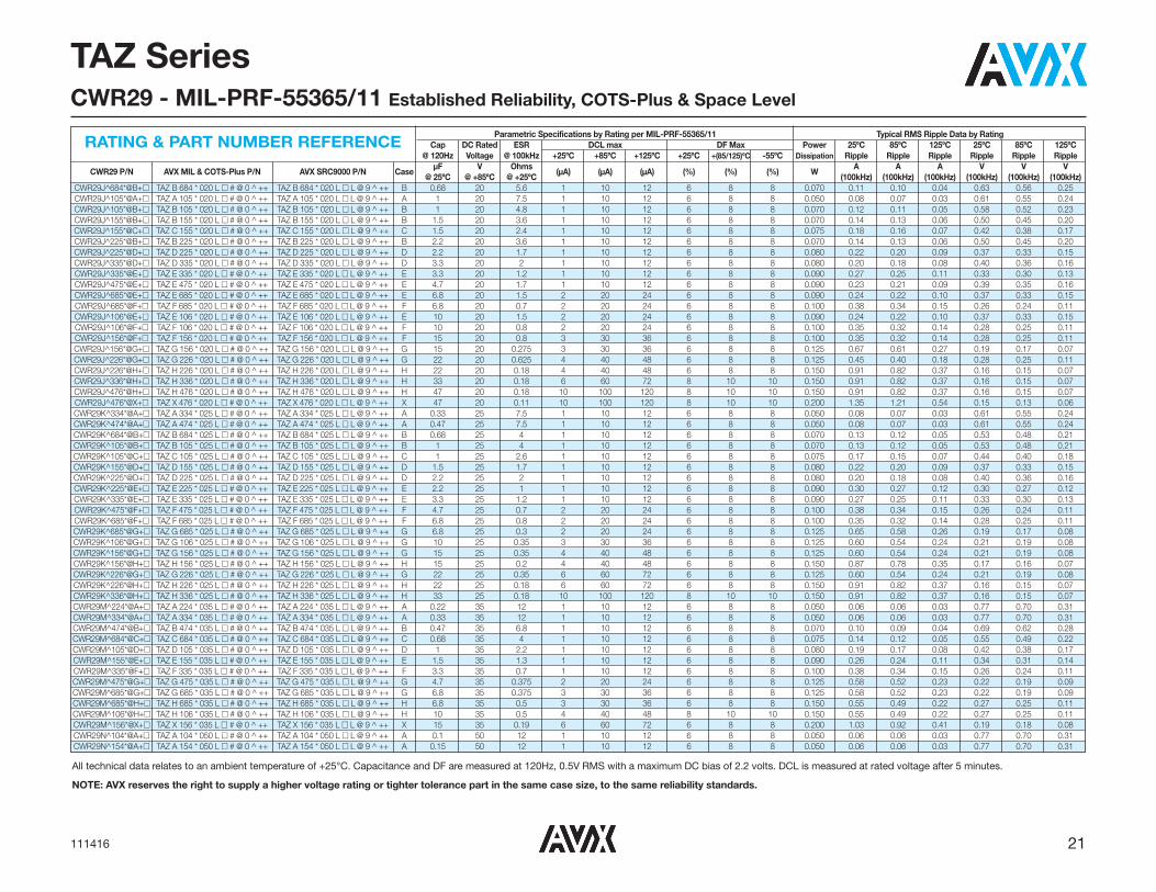
21111416
TAZ SeriesCWR29 - MIL-PRF-55365/11 Established Reliability, COTS-Plus & Space Level
All technical data relates to an ambient temperature of +25°C. Capacitance and DF are measured at 120Hz, 0.5V RMS with a maximum DC bias of 2.2 volts. DCL is measured at rated voltage after 5 minutes.
NOTE: AVX reserves the right to supply a higher voltage rating or tighter tolerance part in the same case size, to the same reliability standards.
Parametric Specifications by Rating per MIL-PRF-55365/11 Typical RMS Ripple Data by RatingCap DC Rated ESR DCL max DF Max Power 25ºC 85ºC 125ºC 25ºC 85ºC 125ºC
@ 120Hz Voltage @ 100kHz +25ºC +85ºC +125ºC +25ºC +(85/125)ºC -55ºC Dissipation Ripple Ripple Ripple Ripple Ripple Ripple
CWR29 P/N AVX MIL & COTS-Plus P/N AVX SRC9000 P/N CaseμF V Ohms
(μA) (μA) (μA) (%) (%) (%) WA A A V V V
@ 25ºC @ +85ºC @ +25ºC (100kHz) (100kHz) (100kHz) (100kHz) (100kHz) (100kHz)CWR29J^684*@B+� TAZ B 684 * 020 L � # @ 0 ^ ++ TAZ B 684 * 020 L � L @ 9 ^ ++ B 0.68 20 5.6 1 10 12 6 8 8 0.070 0.11 0.10 0.04 0.63 0.56 0.25CWR29J^105*@A+� TAZ A 105 * 020 L � # @ 0 ^ ++ TAZ A 105 * 020 L � L @ 9 ^ ++ A 1 20 7.5 1 10 12 6 8 8 0.050 0.08 0.07 0.03 0.61 0.55 0.24CWR29J^105*@B+� TAZ B 105 * 020 L � # @ 0 ^ ++ TAZ B 105 * 020 L � L @ 9 ^ ++ B 1 20 4.8 1 10 12 6 8 8 0.070 0.12 0.11 0.05 0.58 0.52 0.23CWR29J^155*@B+� TAZ B 155 * 020 L � # @ 0 ^ ++ TAZ B 155 * 020 L � L @ 9 ^ ++ B 1.5 20 3.6 1 10 12 6 8 8 0.070 0.14 0.13 0.06 0.50 0.45 0.20CWR29J^155*@C+� TAZ C 155 * 020 L � # @ 0 ^ ++ TAZ C 155 * 020 L � L @ 9 ^ ++ C 1.5 20 2.4 1 10 12 6 8 8 0.075 0.18 0.16 0.07 0.42 0.38 0.17CWR29J^225*@B+� TAZ B 225 * 020 L � # @ 0 ^ ++ TAZ B 225 * 020 L � L @ 9 ^ ++ B 2.2 20 3.6 1 10 12 6 8 8 0.070 0.14 0.13 0.06 0.50 0.45 0.20CWR29J^225*@D+� TAZ D 225 * 020 L � # @ 0 ^ ++ TAZ D 225 * 020 L � L @ 9 ^ ++ D 2.2 20 1.7 1 10 12 6 8 8 0.080 0.22 0.20 0.09 0.37 0.33 0.15CWR29J^335*@D+� TAZ D 335 * 020 L � # @ 0 ^ ++ TAZ D 335 * 020 L � L @ 9 ^ ++ D 3.3 20 2 1 10 12 6 8 8 0.080 0.20 0.18 0.08 0.40 0.36 0.16CWR29J^335*@E+� TAZ E 335 * 020 L � # @ 0 ^ ++ TAZ E 335 * 020 L � L @ 9 ^ ++ E 3.3 20 1.2 1 10 12 6 8 8 0.090 0.27 0.25 0.11 0.33 0.30 0.13CWR29J^475*@E+� TAZ E 475 * 020 L � # @ 0 ^ ++ TAZ E 475 * 020 L � L @ 9 ^ ++ E 4.7 20 1.7 1 10 12 6 8 8 0.090 0.23 0.21 0.09 0.39 0.35 0.16CWR29J^685*@E+� TAZ E 685 * 020 L � # @ 0 ^ ++ TAZ E 685 * 020 L � L @ 9 ^ ++ E 6.8 20 1.5 2 20 24 6 8 8 0.090 0.24 0.22 0.10 0.37 0.33 0.15CWR29J^685*@F+� TAZ F 685 * 020 L � # @ 0 ^ ++ TAZ F 685 * 020 L � L @ 9 ^ ++ F 6.8 20 0.7 2 20 24 6 8 8 0.100 0.38 0.34 0.15 0.26 0.24 0.11CWR29J^106*@E+� TAZ E 106 * 020 L � # @ 0 ^ ++ TAZ E 106 * 020 L � L @ 9 ^ ++ E 10 20 1.5 2 20 24 6 8 8 0.090 0.24 0.22 0.10 0.37 0.33 0.15CWR29J^106*@F+� TAZ F 106 * 020 L � # @ 0 ^ ++ TAZ F 106 * 020 L � L @ 9 ^ ++ F 10 20 0.8 2 20 24 6 8 8 0.100 0.35 0.32 0.14 0.28 0.25 0.11CWR29J^156*@F+� TAZ F 156 * 020 L � # @ 0 ^ ++ TAZ F 156 * 020 L � L @ 9 ^ ++ F 15 20 0.8 3 30 36 6 8 8 0.100 0.35 0.32 0.14 0.28 0.25 0.11CWR29J^156*@G+� TAZ G 156 * 020 L � # @ 0 ^ ++ TAZ G 156 * 020 L � L @ 9 ^ ++ G 15 20 0.275 3 30 36 6 8 8 0.125 0.67 0.61 0.27 0.19 0.17 0.07CWR29J^226*@G+� TAZ G 226 * 020 L � # @ 0 ^ ++ TAZ G 226 * 020 L � L @ 9 ^ ++ G 22 20 0.625 4 40 48 6 8 8 0.125 0.45 0.40 0.18 0.28 0.25 0.11CWR29J^226*@H+� TAZ H 226 * 020 L � # @ 0 ^ ++ TAZ H 226 * 020 L � L @ 9 ^ ++ H 22 20 0.18 4 40 48 6 8 8 0.150 0.91 0.82 0.37 0.16 0.15 0.07CWR29J^336*@H+� TAZ H 336 * 020 L � # @ 0 ^ ++ TAZ H 336 * 020 L � L @ 9 ^ ++ H 33 20 0.18 6 60 72 8 10 10 0.150 0.91 0.82 0.37 0.16 0.15 0.07CWR29J^476*@H+� TAZ H 476 * 020 L � # @ 0 ^ ++ TAZ H 476 * 020 L � L @ 9 ^ ++ H 47 20 0.18 10 100 120 8 10 10 0.150 0.91 0.82 0.37 0.16 0.15 0.07CWR29J^476*@X+� TAZ X 476 * 020 L � # @ 0 ^ ++ TAZ X 476 * 020 L � L @ 9 ^ ++ X 47 20 0.11 10 100 120 8 10 10 0.200 1.35 1.21 0.54 0.15 0.13 0.06CWR29K^334*@A+� TAZ A 334 * 025 L � # @ 0 ^ ++ TAZ A 334 * 025 L � L @ 9 ^ ++ A 0.33 25 7.5 1 10 12 6 8 8 0.050 0.08 0.07 0.03 0.61 0.55 0.24CWR29K^474*@A+� TAZ A 474 * 025 L � # @ 0 ^ ++ TAZ A 474 * 025 L � L @ 9 ^ ++ A 0.47 25 7.5 1 10 12 6 8 8 0.050 0.08 0.07 0.03 0.61 0.55 0.24CWR29K^684*@B+� TAZ B 684 * 025 L � # @ 0 ^ ++ TAZ B 684 * 025 L � L @ 9 ^ ++ B 0.68 25 4 1 10 12 6 8 8 0.070 0.13 0.12 0.05 0.53 0.48 0.21CWR29K^105*@B+� TAZ B 105 * 025 L � # @ 0 ^ ++ TAZ B 105 * 025 L � L @ 9 ^ ++ B 1 25 4 1 10 12 6 8 8 0.070 0.13 0.12 0.05 0.53 0.48 0.21CWR29K^105*@C+� TAZ C 105 * 025 L � # @ 0 ^ ++ TAZ C 105 * 025 L � L @ 9 ^ ++ C 1 25 2.6 1 10 12 6 8 8 0.075 0.17 0.15 0.07 0.44 0.40 0.18CWR29K^155*@D+� TAZ D 155 * 025 L � # @ 0 ^ ++ TAZ D 155 * 025 L � L @ 9 ^ ++ D 1.5 25 1.7 1 10 12 6 8 8 0.080 0.22 0.20 0.09 0.37 0.33 0.15CWR29K^225*@D+� TAZ D 225 * 025 L � # @ 0 ^ ++ TAZ D 225 * 025 L � L @ 9 ^ ++ D 2.2 25 2 1 10 12 6 8 8 0.080 0.20 0.18 0.08 0.40 0.36 0.16CWR29K^225*@E+� TAZ E 225 * 025 L � # @ 0 ^ ++ TAZ E 225 * 025 L � L @ 9 ^ ++ E 2.2 25 1 1 10 12 6 8 8 0.090 0.30 0.27 0.12 0.30 0.27 0.12CWR29K^335*@E+� TAZ E 335 * 025 L � # @ 0 ^ ++ TAZ E 335 * 025 L � L @ 9 ^ ++ E 3.3 25 1.2 1 10 12 6 8 8 0.090 0.27 0.25 0.11 0.33 0.30 0.13CWR29K^475*@F+� TAZ F 475 * 025 L � # @ 0 ^ ++ TAZ F 475 * 025 L � L @ 9 ^ ++ F 4.7 25 0.7 2 20 24 6 8 8 0.100 0.38 0.34 0.15 0.26 0.24 0.11CWR29K^685*@F+� TAZ F 685 * 025 L � # @ 0 ^ ++ TAZ F 685 * 025 L � L @ 9 ^ ++ F 6.8 25 0.8 2 20 24 6 8 8 0.100 0.35 0.32 0.14 0.28 0.25 0.11CWR29K^685*@G+� TAZ G 685 * 025 L � # @ 0 ^ ++ TAZ G 685 * 025 L � L @ 9 ^ ++ G 6.8 25 0.3 2 20 24 6 8 8 0.125 0.65 0.58 0.26 0.19 0.17 0.08CWR29K^106*@G+� TAZ G 106 * 025 L � # @ 0 ^ ++ TAZ G 106 * 025 L � L @ 9 ^ ++ G 10 25 0.35 3 30 36 6 8 8 0.125 0.60 0.54 0.24 0.21 0.19 0.08CWR29K^156*@G+� TAZ G 156 * 025 L � # @ 0 ^ ++ TAZ G 156 * 025 L � L @ 9 ^ ++ G 15 25 0.35 4 40 48 6 8 8 0.125 0.60 0.54 0.24 0.21 0.19 0.08CWR29K^156*@H+� TAZ H 156 * 025 L � # @ 0 ^ ++ TAZ H 156 * 025 L � L @ 9 ^ ++ H 15 25 0.2 4 40 48 6 8 8 0.150 0.87 0.78 0.35 0.17 0.16 0.07CWR29K^226*@G+� TAZ G 226 * 025 L � # @ 0 ^ ++ TAZ G 226 * 025 L � L @ 9 ^ ++ G 22 25 0.35 6 60 72 6 8 8 0.125 0.60 0.54 0.24 0.21 0.19 0.08CWR29K^226*@H+� TAZ H 226 * 025 L � # @ 0 ^ ++ TAZ H 226 * 025 L � L @ 9 ^ ++ H 22 25 0.18 6 60 72 6 8 8 0.150 0.91 0.82 0.37 0.16 0.15 0.07CWR29K^336*@H+� TAZ H 336 * 025 L � # @ 0 ^ ++ TAZ H 336 * 025 L � L @ 9 ^ ++ H 33 25 0.18 10 100 120 8 10 10 0.150 0.91 0.82 0.37 0.16 0.15 0.07CWR29M^224*@A+� TAZ A 224 * 035 L � # @ 0 ^ ++ TAZ A 224 * 035 L � L @ 9 ^ ++ A 0.22 35 12 1 10 12 6 8 8 0.050 0.06 0.06 0.03 0.77 0.70 0.31CWR29M^334*@A+� TAZ A 334 * 035 L � # @ 0 ^ ++ TAZ A 334 * 035 L � L @ 9 ^ ++ A 0.33 35 12 1 10 12 6 8 8 0.050 0.06 0.06 0.03 0.77 0.70 0.31CWR29M^474*@B+� TAZ B 474 * 035 L � # @ 0 ^ ++ TAZ B 474 * 035 L � L @ 9 ^ ++ B 0.47 35 6.8 1 10 12 6 8 8 0.070 0.10 0.09 0.04 0.69 0.62 0.28CWR29M^684*@C+� TAZ C 684 * 035 L � # @ 0 ^ ++ TAZ C 684 * 035 L � L @ 9 ^ ++ C 0.68 35 4 1 10 12 6 8 8 0.075 0.14 0.12 0.05 0.55 0.49 0.22CWR29M^105*@D+� TAZ D 105 * 035 L � # @ 0 ^ ++ TAZ D 105 * 035 L � L @ 9 ^ ++ D 1 35 2.2 1 10 12 6 8 8 0.080 0.19 0.17 0.08 0.42 0.38 0.17CWR29M^155*@E+� TAZ E 155 * 035 L � # @ 0 ^ ++ TAZ E 155 * 035 L � L @ 9 ^ ++ E 1.5 35 1.3 1 10 12 6 8 8 0.090 0.26 0.24 0.11 0.34 0.31 0.14CWR29M^335*@F+� TAZ F 335 * 035 L � # @ 0 ^ ++ TAZ F 335 * 035 L � L @ 9 ^ ++ F 3.3 35 0.7 1 10 12 6 8 8 0.100 0.38 0.34 0.15 0.26 0.24 0.11CWR29M^475*@G+� TAZ G 475 * 035 L � # @ 0 ^ ++ TAZ G 475 * 035 L � L @ 9 ^ ++ G 4.7 35 0.375 2 20 24 6 8 8 0.125 0.58 0.52 0.23 0.22 0.19 0.09CWR29M^685*@G+� TAZ G 685 * 035 L � # @ 0 ^ ++ TAZ G 685 * 035 L � L @ 9 ^ ++ G 6.8 35 0.375 3 30 36 6 8 8 0.125 0.58 0.52 0.23 0.22 0.19 0.09CWR29M^685*@H+� TAZ H 685 * 035 L � # @ 0 ^ ++ TAZ H 685 * 035 L � L @ 9 ^ ++ H 6.8 35 0.5 3 30 36 6 8 8 0.150 0.55 0.49 0.22 0.27 0.25 0.11CWR29M^106*@H+� TAZ H 106 * 035 L � # @ 0 ^ ++ TAZ H 106 * 035 L � L @ 9 ^ ++ H 10 35 0.5 4 40 48 8 10 10 0.150 0.55 0.49 0.22 0.27 0.25 0.11CWR29M^156*@X+� TAZ X 156 * 035 L � # @ 0 ^ ++ TAZ X 156 * 035 L � L @ 9 ^ ++ X 15 35 0.19 6 60 72 6 8 8 0.200 1.03 0.92 0.41 0.19 0.18 0.08CWR29N^104*@A+� TAZ A 104 * 050 L � # @ 0 ^ ++ TAZ A 104 * 050 L � L @ 9 ^ ++ A 0.1 50 12 1 10 12 6 8 8 0.050 0.06 0.06 0.03 0.77 0.70 0.31CWR29N^154*@A+� TAZ A 154 * 050 L � # @ 0 ^ ++ TAZ A 154 * 050 L � L @ 9 ^ ++ A 0.15 50 12 1 10 12 6 8 8 0.050 0.06 0.06 0.03 0.77 0.70 0.31
RATING & PART NUMBER REFERENCE

22 111416
TAZ SeriesCWR29 - MIL-PRF-55365/11 Established Reliability, COTS-Plus & Space Level
Parametric Specifications by Rating per MIL-PRF-55365/11 Typical RMS Ripple Data by RatingCap DC Rated ESR DCL max DF Max Power 25ºC 85ºC 125ºC 25ºC 85ºC 125ºC
@ 120Hz Voltage @ 100kHz +25ºC +85ºC +125ºC +25ºC +(85/125)ºC -55ºC Dissipation Ripple Ripple Ripple Ripple Ripple Ripple
CWR29 P/N AVX MIL & COTS-Plus P/N AVX SRC9000 P/N CaseμF V Ohms
(μA) (μA) (μA) (%) (%) (%) WA A A V V V
@ 25ºC @ +85ºC @ +25ºC (100kHz) (100kHz) (100kHz) (100kHz) (100kHz) (100kHz)CWR29N^224*@B+� TAZ B 224 * 050 L � # @ 0 ^ ++ TAZ B 224 * 050 L � L @ 9 ^ ++ B 0.22 50 6.8 1 10 12 6 8 8 0.070 0.10 0.09 0.04 0.69 0.62 0.28CWR29N^334*@B+� TAZ B 334 * 050 L � # @ 0 ^ ++ TAZ B 334 * 050 L � L @ 9 ^ ++ B 0.33 50 4.8 1 10 12 6 8 8 0.070 0.12 0.11 0.05 0.58 0.52 0.23CWR29N^474*@C+� TAZ C 474 * 050 L � # @ 0 ^ ++ TAZ C 474 * 050 L � L @ 9 ^ ++ C 0.47 50 3.2 1 10 12 6 8 8 0.075 0.15 0.14 0.06 0.49 0.44 0.20CWR29N^684*@D+� TAZ D 684 * 050 L � # @ 0 ^ ++ TAZ D 684 * 050 L � L @ 9 ^ ++ D 0.68 50 2.3 1 10 12 6 8 8 0.080 0.19 0.17 0.07 0.43 0.39 0.17CWR29N^105*@E+� TAZ E 105 * 050 L � # @ 0 ^ ++ TAZ E 105 * 050 L � L @ 9 ^ ++ E 1 50 1.7 1 10 12 6 8 8 0.090 0.23 0.21 0.09 0.39 0.35 0.16CWR29N^155*@F+� TAZ F 155 * 050 L � # @ 0 ^ ++ TAZ F 155 * 050 L � L @ 9 ^ ++ F 1.5 50 1.1 1 10 12 6 8 8 0.100 0.30 0.27 0.12 0.33 0.30 0.13CWR29N^225*@F+� TAZ F 225 * 050 L � # @ 0 ^ ++ TAZ F 225 * 050 L � L @ 9 ^ ++ F 2.2 50 0.7 2 20 24 6 8 8 0.100 0.38 0.34 0.15 0.26 0.24 0.11CWR29N^335*@G+� TAZ G 335 * 050 L � # @ 0 ^ ++ TAZ G 335 * 050 L � L @ 9 ^ ++ G 3.3 50 0.5 2 20 24 6 8 8 0.125 0.50 0.45 0.20 0.25 0.23 0.10CWR29N^475*@H+� TAZ H 475 * 050 L � # @ 0 ^ ++ TAZ H 475 * 050 L � L @ 9 ^ ++ H 4.7 50 0.5 3 30 36 6 8 8 0.150 0.55 0.49 0.22 0.27 0.25 0.11
RATING & PART NUMBER REFERENCE
All technical data relates to an ambient temperature of +25°C. Capacitance and DF are measured at 120Hz, 0.5V RMS with a maximum DC bias of 2.2 volts. DCL is measured at rated voltage after 5 minutes.
NOTE: AVX reserves the right to supply a higher voltage rating or tighter tolerance part in the same case size, to the same reliability standards.

23041416
The TAZ HRC5000 Medical Grade series isdesigned for use in medical implantableapplications. These are based off of the MIL-PRF-55365 case sizes and feature extremely lowDC leakage levels well below typical values.
These components are manufactured and testedin the AVX Biddeford Maine factory which is ISO13485 certified. Weibull grading and surgecurrent testing options per MIL-PRF-55365 are
available along with several plating optionsincluding tin/lead solder, 100% tin, or goldterminations.
To request an additional rating not listed here, orfor more information on HRC5000 testing details,please contact the factory.
For moisture sensitivity levels please refer to theHigh Reliability Tantalum MSL section located inthe back of the High Reliability Tantalum Catalog.
MARKING(White marking on black body)
Polarity Stripe (+)
Capacitance CodeRated Voltage
TAZ SeriesHRC5000 Medical Implantable Grade
CASE DIMENSIONS: millimeters (inches)
Case Length (L) Width (W) Height (H) Term. Length (A)
TypicalCode ±0.38 (0.015) ±0.38 (0.015) ±0.38 (0.015)
Term. Width (W1) +0.25/-0.13 S min Weight (g) (+0.010/-0.005)
A 2.54 (0.100) 1.27 (0.050) 1.27 (0.050)
1.27±0.13 0.76 (0.030) 0.38 (0.015) 0.016 (0.050±0.005)
B 3.81 (0.150) 1.27 (0.050) 1.27 (0.050)
1.27±0.13 0.76 (0.030) 1.65 (0.065) 0.025 (0.050±0.005)
C 5.08 (0.200) 1.27 (0.050) 1.27 (0.050) 1.27±0.13
0.76 (0.030) 2.92 (0.115) 0.035 (0.050±0.005)
D 3.81 (0.150) 2.54 (0.100) 1.27 (0.050) 2.41+0.13/-0.25
0.76 (0.030) 1.65 (0.065) 0.045 (0.095+0.005/-0.010)
E 5.08 (0.200) 2.54 (0.100) 1.27 (0.050)
2.41+0.13/-0.25 0.76 (0.030) 2.92 (0.115) 0.065 (0.095+0.005/-0.010)
F 5.59 (0.220) 3.43 (0.135) 1.78 (0.070)
3.30±0.13 0.76 (0.030) 3.43 (0.135) 0.125 (0.130±0.005)
G 6.73 (0.265) 2.79 (0.110) 2.79 (0.110)
2.67±0.13 1.27 (0.050) 3.56 (0.140) 0.205 (0.105±0.005)
H 7.24 (0.285) 3.81 (0.150) 2.79 (0.110)
3.68+0.13/-0.51 1.27 (0.050) 4.06 (0.160) 0.335 (0.145+0.005/-0.020)
Capacitance Rated Voltage μF Code 4V 6V 10V 12V 15V 20V 25V 35V 50V 0.10 104 A 0.15 154 A 0.22 224 A 0.33 334 A 0.47 474 A B 0.68 684 A 1 105 A A A/B B D E 1.5 155 A A B D 2.2 225 A A A/B A/B/C B/D D/E F 3.3 335 A/B A/B B/D E E F G 4.7 475 A/B A B/D B/D/E D/E F 6 605 6.8 685 A D B/D/E D/E F 10 106 D B/D/E B/D/E D/E/F E G H 14 146 E 15 156 B/D/F D/E/F E F/G 22 226 F D/E/F E F/G G/H H 33 336 E/F E F/G F/H 47 476 E E/F/G F/G/H G H 68 686 E/G E/F/G/H G 100 107 F G H H 150 157 G H 220 227 H 300 307 H 330 337 H
CAPACITANCE AND RATED VOLTAGE, VR (VOLTAGE CODE) RANGE (LETTER DENOTES CASE SIZE)

24 041416
TAZ SeriesHRC5000 Medical Implantable Grade
*
CapacitanceTolerance
J = ±5% K = ±10% M = ±20%
�
Packaging B = Bulk R = 7" T&RW = Waffle
++
Surge TestOption
00 = None23 = 10 Cycles, +25ºC24 = 10 Cycles,
-55ºC & +85ºC45 = 10 Cycles,
-55ºC & +85ºCbefore Weibull
TAZ
Type
E
CaseSize
C
ESRC = Std ESRL = Low ESR
L
Inspection LevelL = Group A
HOW TO ORDER010
VoltageCode
004 = 4Vdc006 = 6Vdc010 = 10Vdc015 = 15Vdc020 = 20Vdc025 = 25Vdc035 = 35Vdc050 = 50Vdc
106
CapacitanceCode
pF code: 1st two digits
representsignificant figures 3rd
digit representsmultiplier
(number ofzeros to follow)
@
Reliability GradeWeibull:
B = 0.1%/1000 hrs.90% conf.
C = 0.01%/1000 hrs.90% conf.
^
Termination FinishH = Solder Plated0 = Solder Fused9 = Gold Plated7 =100% Tin
5
QualificationLevel5 =
HRC5000
*Contact factory for AVX HRC5000 Medical Grade SCD details.
LEAD-FREE COMPATIBLECOMPONENT
For RoHS compliant products, please select correct termination style.
Technical Data: Unless otherwise specified, all technical data relate to an ambient temperature of 25°CCapacitance Range: 0.10 μF to 330 μFCapacitance Tolerance: ±5%; ±10%; ±20%Rated Voltage (VR) � 85°C: 4 6 10 15 20 25 35 50Category Voltage (VC) � 125°C: 2.7 4 6.7 10 13.3 16.7 23.3 33.3Surge Voltage (VS) � 85°C: 5.3 8 13.3 20 26.7 33.3 46.7 66.7Surge Voltage (VS) � 125°C: 3.5 5.3 8.7 13.3 17.8 22.2 31.1 44.5Temperature Range: -55°C to +125°C
TECHNICAL SPECIFICATIONS

25041416
TAZ SeriesHRC5000 Medical Implantable Grade
All technical data relates to an ambient temperature of +25°C. Capacitance and DF are measured at 120Hz, 0.5V RMS with a maximum DC bias of 2.2 volts. DCL is measured at rated voltage after 5 minutes.
NOTE: AVX reserves the right to supply a higher voltage rating or tighter tolerance part in the same case size, to the same reliability standards.
Parametric Specifications by Rating Typical RMS Ripple Data by Rating
Cap DC Rated ESR DCL max DF max Power 25ºC 85ºC 125ºC 25ºC 85ºC 125ºC
@ 120Hz Voltage @ 100kHz +25°C +85°C +125°C +25°C +(85/125)°C -55°C Dissipation Ripple Ripple Ripple Ripple Ripple RippleCurrent Current Current Voltage Voltage Voltage
AVX P/N Case μF V Ohms (μA) (μA) (μA) (%) (%) (%) W A A A V V V@ 25ºC @ +85ºC @ +25ºC (100kHz) (100kHz) (100kHz) (100kHz) (100kHz) (100kHz)
TAZA225*004L�L@5^++ A 2.2 4 4 0.100 1.000 1.200 6 8 8 0.050 0.112 0.101 0.045 0.447 0.402 0.179TAZA475*004L�L@5^++ A 4.7 4 6 0.100 1.000 1.200 6 8 8 0.050 0.091 0.082 0.037 0.548 0.493 0.219TAZB475*004L�L@5^++ B 4.7 4 3.2 0.100 1.000 1.200 6 8 8 0.070 0.148 0.133 0.059 0.473 0.426 0.189TAZA685*004L�L@5^++ A 6.8 4 6 0.100 1.000 1.200 6 8 8 0.050 0.091 0.082 0.037 0.548 0.493 0.219TAZD106*004L�L@5^++ D 10 4 1.3 0.100 1.000 1.200 8 8 10 0.080 0.248 0.223 0.099 0.322 0.290 0.129TAZE336*004L�L@5^++ E 33 4 0.9 0.330 3.300 3.960 8 10 12 0.090 0.316 0.285 0.126 0.285 0.256 0.114TAZF336*004L�L@5^++ F 33 4 0.6 0.330 3.300 3.960 8 10 12 0.100 0.408 0.367 0.163 0.245 0.220 0.098TAZE476*004L�L@5^++ E 47 4 0.9 0.470 4.700 5.640 8 10 12 0.090 0.316 0.285 0.126 0.285 0.256 0.114TAZE686*004L�L@5^++ E 68 4 0.9 0.680 6.800 8.160 8 10 12 0.090 0.316 0.285 0.126 0.285 0.256 0.114TAZG686*004L�L@5^++ G 68 4 0.275 0.680 6.800 8.160 10 12 12 0.125 0.674 0.607 0.270 0.185 0.167 0.074TAZF107*004L�L@5^++ F 100 4 0.55 1.000 10.000 12.000 10 12 12 0.100 0.426 0.384 0.171 0.235 0.211 0.094TAZA155*006L�L@5^++ A 1.5 6 4 0.100 1.000 1.200 6 8 8 0.050 0.112 0.101 0.045 0.447 0.402 0.179TAZA225*006C�L@5^++ A 2.2 6 12 0.100 1.000 1.200 6 8 8 0.050 0.065 0.058 0.026 0.775 0.697 0.310TAZA335*006L�L@5^++ A 3.3 6 6 0.100 1.000 1.200 6 8 8 0.050 0.091 0.082 0.037 0.548 0.493 0.219TAZB335*006L�L@5^++ B 3.3 6 3.2 0.100 1.000 1.200 6 8 8 0.070 0.148 0.133 0.059 0.473 0.426 0.189TAZA475*006L�L@5^++ A 4.7 6 6 0.100 1.000 1.200 6 8 8 0.050 0.091 0.082 0.037 0.548 0.493 0.219TAZD685*006L�L@5^++ D 6.8 6 1.5 0.102 1.020 1.224 6 8 8 0.080 0.231 0.208 0.092 0.346 0.312 0.139TAZB106*006L�L@5^++ B 10 6 3.2 0.150 1.500 1.800 6 8 8 0.070 0.148 0.133 0.059 0.473 0.426 0.189TAZD106*006C�L@5^++ D 10 6 6 0.150 1.500 1.800 6 8 8 0.080 0.115 0.104 0.046 0.693 0.624 0.277TAZE106*006L�L@5^++ E 10 6 1 0.150 1.500 1.800 8 10 12 0.090 0.300 0.270 0.120 0.300 0.270 0.120TAZB156*006L�L@5^++ B 15 6 3.2 0.225 2.250 2.700 8 10 10 0.070 0.148 0.133 0.059 0.473 0.426 0.189TAZD156*006L�L@5^++ D 15 6 1.7 0.225 2.250 2.700 8 10 12 0.080 0.217 0.195 0.087 0.369 0.332 0.148TAZF156*006C�L@5^++ F 15 6 0.3 0.225 2.250 2.700 6 8 8 0.100 0.577 0.520 0.231 0.173 0.156 0.069TAZF226*006L�L@5^++ F 22 6 0.6 0.330 3.300 3.960 8 10 12 0.100 0.408 0.367 0.163 0.245 0.220 0.098TAZE336*006L�L@5^++ E 33 6 1 0.495 4.950 5.940 6 8 8 0.090 0.300 0.270 0.120 0.300 0.270 0.120TAZE476*006C�L@5^++ E 47 6 5 0.705 7.050 8.460 6 8 8 0.090 0.134 0.121 0.054 0.671 0.604 0.268TAZF476*006L�L@5^++ F 47 6 1 0.705 7.050 8.460 8 10 12 0.100 0.316 0.285 0.126 0.316 0.285 0.126TAZG476*006L�L@5^++ G 47 6 0.275 0.705 7.050 8.460 10 12 12 0.125 0.674 0.607 0.270 0.185 0.167 0.074TAZE686*006C�L@5^++ E 68 6 2 1.020 10.200 12.240 10 12 12 0.090 0.212 0.191 0.085 0.424 0.382 0.170TAZF686*006L�L@5^++ F 68 6 0.4 1.020 10.200 12.240 10 12 12 0.100 0.500 0.450 0.200 0.200 0.180 0.080TAZG686*006L�L@5^++ G 68 6 0.25 1.020 10.200 12.240 10 12 12 0.125 0.707 0.636 0.283 0.177 0.159 0.071TAZH686*006L�L@5^++ H 68 6 0.18 1.020 10.200 12.240 10 12 12 0.150 0.913 0.822 0.365 0.164 0.148 0.066TAZG107*006L�L@5^++ G 100 6 0.275 1.500 15.000 18.000 10 12 12 0.125 0.674 0.607 0.270 0.185 0.167 0.074TAZG157*006L�L@5^++ G 150 6 0.275 2.250 22.500 27.000 10 12 12 0.125 0.674 0.607 0.270 0.185 0.167 0.074TAZH307*006C�L@5^++ H 300 6 0.9 4.500 45.000 54.000 15 18 18 0.150 0.408 0.367 0.163 0.367 0.331 0.147TAZH337*006L�L@5^++ H 330 6 0.18 4.950 49.500 59.400 10 12 12 0.150 0.913 0.822 0.365 0.164 0.148 0.066TAZR334*010C�L@5^++ R 0.33 10 50 0.100 1.000 1.200 6 8 8 0.030 0.024 0.022 0.010 1.225 1.102 0.490TAZA105*010L�L@5^++ A 1 10 5 0.100 1.000 1.200 6 8 8 0.050 0.100 0.090 0.040 0.500 0.450 0.200TAZA155*010C�L@5^++ A 1.5 10 12 0.100 1.000 1.200 6 8 8 0.050 0.065 0.058 0.026 0.775 0.697 0.310TAZA225*010L�L@5^++ A 2.2 10 6 0.100 1.000 1.200 6 8 8 0.050 0.091 0.082 0.037 0.548 0.493 0.219TAZB225*010L�L@5^++ B 2.2 10 3.2 0.100 1.000 1.200 6 8 8 0.070 0.148 0.133 0.059 0.473 0.426 0.189TAZA335*010L�L@5^++ A 3.3 10 6 0.100 1.000 1.200 6 8 8 0.050 0.091 0.082 0.037 0.548 0.493 0.219TAZB335*010C�L@5^++ B 3.3 10 18 0.100 1.000 1.200 6 8 8 0.070 0.062 0.056 0.025 1.122 1.010 0.449
RATING & PART NUMBER REFERENCE

26 041416
TAZ SeriesHRC5000 Medical Implantable Grade
All technical data relates to an ambient temperature of +25°C. Capacitance and DF are measured at 120Hz, 0.5V RMS with a maximum DC bias of 2.2 volts. DCL is measured at rated voltage after 5 minutes.
NOTE: AVX reserves the right to supply a higher voltage rating or tighter tolerance part in the same case size, to the same reliability standards.
Parametric Specifications by Rating Typical RMS Ripple Data by Rating
Cap DC Rated ESR DCL max DF max Power 25ºC 85ºC 125ºC 25ºC 85ºC 125ºC
@ 120Hz Voltage @ 100kHz +25°C +85°C +125°C +25°C +(85/125)°C -55°C Dissipation Ripple Ripple Ripple Ripple Ripple RippleCurrent Current Current Voltage Voltage Voltage
AVX P/N Case μF V Ohms (μA) (μA) (μA) (%) (%) (%) W A A A V V V@ 25ºC @ +85ºC @ +25ºC (100kHz) (100kHz) (100kHz) (100kHz) (100kHz) (100kHz)
TAZB475*010L�L@5^++ B 4.7 10 3.2 0.200 2.000 2.400 6 8 8 0.070 0.148 0.133 0.059 0.473 0.426 0.189TAZD475*010L�L@5^++ D 4.7 10 1.5 0.200 2.000 2.400 6 8 8 0.080 0.231 0.208 0.092 0.346 0.312 0.139TAZB685*010L�L@5^++ B 6.8 10 3.2 0.170 1.700 2.040 6 8 8 0.070 0.148 0.133 0.059 0.473 0.426 0.189TAZD685*010L�L@5^++ D 6.8 10 1.7 0.170 1.700 2.040 6 8 8 0.080 0.217 0.195 0.087 0.369 0.332 0.148TAZE685*010L�L@5^++ E 6.8 10 1 0.170 1.700 2.040 6 8 8 0.090 0.300 0.270 0.120 0.300 0.270 0.120TAZB106*010L�L@5^++ B 10 10 3.2 0.250 2.500 3.000 8 10 10 0.070 0.148 0.133 0.059 0.473 0.426 0.189TAZD106*010L�L@5^++ D 10 10 1.3 0.250 2.500 3.000 6 8 8 0.080 0.248 0.223 0.099 0.322 0.290 0.129TAZE106*010L�L@5^++ E 10 10 1 0.250 2.500 3.000 6 8 8 0.090 0.300 0.270 0.120 0.300 0.270 0.120TAZE146*010C�L@5^++ E 14 10 3 0.350 3.500 4.200 6 8 8 0.090 0.173 0.156 0.069 0.520 0.468 0.208TAZD156*010L�L@5^++ D 15 10 1.7 0.375 3.750 4.500 6 8 8 0.080 0.217 0.195 0.087 0.369 0.332 0.148TAZE156*010L�L@5^++ E 15 10 0.9 0.375 3.750 4.500 8 10 10 0.090 0.316 0.285 0.126 0.285 0.256 0.114TAZF156*010L�L@5^++ F 15 10 0.7 0.375 3.750 4.500 8 8 10 0.100 0.378 0.340 0.151 0.265 0.238 0.106TAZD226*010C�L@5^++ D 22 10 8 0.550 5.500 6.600 6 8 8 0.080 0.100 0.090 0.040 0.800 0.720 0.320TAZE226*010L�L@5^++ E 22 10 0.6 0.550 5.500 6.600 8 10 10 0.090 0.387 0.349 0.155 0.232 0.209 0.093TAZF226*010C�L@5^++ F 22 10 3 0.550 5.500 6.600 8 10 10 0.100 0.183 0.164 0.073 0.548 0.493 0.219TAZF336*010L�L@5^++ F 33 10 0.4 0.825 8.250 9.900 8 10 10 0.100 0.500 0.450 0.200 0.200 0.180 0.080TAZG336*010L�L@5^++ G 33 10 0.275 0.825 8.250 9.900 10 12 12 0.125 0.674 0.607 0.270 0.185 0.167 0.074TAZF476*010L�L@5^++ F 47 10 0.4 1.175 11.750 14.100 10 12 12 0.100 0.500 0.450 0.200 0.200 0.180 0.080TAZG476*010L�L@5^++ G 47 10 0.25 1.175 11.750 14.100 10 12 12 0.125 0.707 0.636 0.283 0.177 0.159 0.071TAZH476*010L�L@5^++ H 47 10 0.18 1.175 11.750 14.100 10 12 12 0.150 0.913 0.822 0.365 0.164 0.148 0.066TAZG686*010L�L@5^++ G 68 10 0.275 1.700 17.000 20.400 10 12 12 0.125 0.674 0.607 0.270 0.185 0.167 0.074TAZH107*010L�L@5^++ H 100 10 0.18 2.500 25.000 30.000 10 12 12 0.150 0.913 0.822 0.365 0.164 0.148 0.066TAZH157*010L�L@5^++ H 150 10 0.18 3.750 37.500 45.000 10 12 12 0.150 0.913 0.822 0.365 0.164 0.148 0.066TAZH227*010L�L@5^++ H 220 10 0.18 5.500 55.000 66.000 10 12 12 0.150 0.913 0.822 0.365 0.164 0.148 0.066TAZE226*012C�L@5^++ E 22 12 0.5 0.660 6.600 7.920 6 8 8 0.090 0.424 0.382 0.170 0.212 0.191 0.085TAZA684*015L�L@5^++ A 0.68 15 6 0.100 1.000 1.200 6 8 8 0.050 0.091 0.082 0.037 0.548 0.493 0.219TAZA105*015L�L@5^++ A 1 15 7.5 0.100 1.000 1.200 6 8 8 0.050 0.082 0.073 0.033 0.612 0.551 0.245TAZA225*015L�L@5^++ A 2.2 15 7.5 0.200 2.000 2.400 6 8 8 0.050 0.082 0.073 0.033 0.612 0.551 0.245TAZB225*015C�L@5^++ B 2.2 15 5.5 0.100 1.000 1.200 6 8 8 0.070 0.113 0.102 0.045 0.620 0.558 0.248TAZB335*015L�L@5^++ B 3.3 15 3.6 0.290 2.900 3.480 6 8 8 0.070 0.139 0.125 0.056 0.502 0.452 0.201TAZD335*015L�L@5^++ D 3.3 15 1.7 0.124 1.238 1.485 6 8 8 0.080 0.217 0.195 0.087 0.369 0.332 0.148TAZB475*015L�L@5^++ B 4.7 15 2 0.250 2.500 3.000 6 8 8 0.070 0.187 0.168 0.075 0.374 0.337 0.150TAZD475*015L�L@5^++ D 4.7 15 2 0.250 2.500 3.000 6 8 8 0.080 0.200 0.180 0.080 0.400 0.360 0.160TAZE475*015L�L@5^++ E 4.7 15 1.2 0.245 2.450 2.940 6 8 8 0.090 0.274 0.246 0.110 0.329 0.296 0.131TAZD106*015L�L@5^++ D 10 15 2 0.375 3.750 4.500 6 8 8 0.080 0.200 0.180 0.080 0.400 0.360 0.160TAZE106*015L�L@5^++ E 10 15 1.2 0.375 3.750 4.500 6 8 8 0.090 0.274 0.246 0.110 0.329 0.296 0.131TAZF106*015L�L@5^++ F 10 15 0.667 0.375 3.750 4.500 6 8 8 0.100 0.387 0.348 0.155 0.258 0.232 0.103TAZE156*015L�L@5^++ E 15 15 1.2 0.563 5.625 6.750 6 8 8 0.090 0.274 0.246 0.110 0.329 0.296 0.131TAZF226*015L�L@5^++ F 22 15 0.8 0.825 8.250 9.900 8 10 10 0.100 0.354 0.318 0.141 0.283 0.255 0.113TAZG226*015L�L@5^++ G 22 15 0.275 0.825 8.250 9.900 6 8 8 0.125 0.674 0.607 0.270 0.185 0.167 0.074TAZF336*015L�L@5^++ F 33 15 0.8 1.238 12.375 14.850 6 8 8 0.100 0.354 0.318 0.141 0.283 0.255 0.113TAZH336*015L�L@5^++ H 33 15 0.18 1.238 12.375 14.850 8 8 10 0.150 0.913 0.822 0.365 0.164 0.148 0.066TAZG476*015L�L@5^++ G 47 15 0.275 1.763 17.625 21.150 8 10 10 0.125 0.674 0.607 0.270 0.185 0.167 0.074
RATING & PART NUMBER REFERENCE

27041416
TAZ SeriesHRC5000 Medical Implantable Grade
All technical data relates to an ambient temperature of +25°C. Capacitance and DF are measured at 120Hz, 0.5V RMS with a maximum DC bias of 2.2 volts. DCL is measured at rated voltage after 5 minutes.
NOTE: AVX reserves the right to supply a higher voltage rating or tighter tolerance part in the same case size, to the same reliability standards.
Parametric Specifications by Rating Typical RMS Ripple Data by Rating
Cap DC Rated ESR DCL max DF max Power 25ºC 85ºC 125ºC 25ºC 85ºC 125ºC
@ 120Hz Voltage @ 100kHz +25°C +85°C +125°C +25°C +(85/125)°C -55°C Dissipation Ripple Ripple Ripple Ripple Ripple RippleCurrent Current Current Voltage Voltage Voltage
AVX P/N Case μF V Ohms (μA) (μA) (μA) (%) (%) (%) W A A A V V V@ 25ºC @ +85ºC @ +25ºC (100kHz) (100kHz) (100kHz) (100kHz) (100kHz) (100kHz)
TAZH107*015L�L@5^++ H 100 15 0.18 3.750 37.500 45.000 10 12 12 0.150 0.913 0.822 0.365 0.164 0.148 0.066TAZA474*020L�L@5^++ A 0.47 20 7.5 0.100 1.000 1.200 8 8 10 0.050 0.082 0.073 0.033 0.612 0.551 0.245TAZA105*020L�L@5^++ A 1 20 7.5 0.100 1.000 1.200 6 8 8 0.050 0.082 0.073 0.033 0.612 0.551 0.245TAZB105*020L�L@5^++ B 1 20 4.8 0.100 1.000 1.200 6 8 8 0.070 0.121 0.109 0.048 0.580 0.522 0.232TAZB155*020L�L@5^++ B 1.5 20 3.6 0.100 1.000 1.200 6 8 8 0.070 0.139 0.125 0.056 0.502 0.452 0.201TAZB225*020L�L@5^++ B 2.2 20 3.6 0.110 1.100 1.320 6 8 8 0.070 0.139 0.125 0.056 0.502 0.452 0.201TAZD225*020L�L@5^++ D 2.2 20 1.7 0.225 2.250 2.700 6 8 8 0.080 0.217 0.195 0.087 0.369 0.332 0.148TAZE335*020L�L@5^++ E 3.3 20 1.2 0.165 1.650 1.980 6 8 8 0.090 0.274 0.246 0.110 0.329 0.296 0.131TAZD475*020C�L@5^++ D 4.7 20 6 0.235 2.350 2.820 6 8 8 0.080 0.115 0.104 0.046 0.693 0.624 0.277TAZE475*020L�L@5^++ E 4.7 20 1.7 0.235 2.350 2.820 6 8 8 0.090 0.230 0.207 0.092 0.391 0.352 0.156TAZD685*020C�L@5^++ D 6.8 20 4 0.450 4.500 5.400 6 8 8 0.080 0.141 0.127 0.057 0.566 0.509 0.226TAZE685*020L�L@5^++ E 6.8 20 1.5 0.450 4.500 5.400 6 8 8 0.090 0.245 0.220 0.098 0.367 0.331 0.147TAZE106*020L�L@5^++ E 10 20 1.5 0.500 5.000 6.000 6 8 8 0.090 0.245 0.220 0.098 0.367 0.331 0.147TAZF156*020L�L@5^++ F 15 20 0.8 0.750 7.500 9.000 6 8 8 0.100 0.354 0.318 0.141 0.283 0.255 0.113TAZG156*020L�L@5^++ G 15 20 0.275 0.750 7.500 9.000 6 8 8 0.125 0.674 0.607 0.270 0.185 0.167 0.074TAZG226*020L�L@5^++ G 22 20 0.625 1.100 11.000 13.200 6 8 8 0.125 0.447 0.402 0.179 0.280 0.252 0.112TAZH226*020L�L@5^++ H 22 20 0.18 1.100 11.000 13.200 6 8 8 0.150 0.913 0.822 0.365 0.164 0.148 0.066TAZH476*020L�L@5^++ H 47 20 0.18 2.350 23.500 28.200 8 10 10 0.150 0.913 0.822 0.365 0.164 0.148 0.066TAZA334*025L�L@5^++ A 0.33 25 15 0.100 1.000 1.200 6 8 8 0.050 0.058 0.052 0.023 0.866 0.779 0.346TAZB105*025L�L@5^++ B 1 25 4 0.160 1.600 1.920 6 8 8 0.070 0.132 0.119 0.053 0.529 0.476 0.212TAZD155*025L�L@5^++ D 1.5 25 1.7 0.200 2.000 2.400 6 8 8 0.080 0.217 0.195 0.087 0.369 0.332 0.148TAZD225*025L�L@5^++ D 2.2 25 2 0.215 2.150 2.580 6 8 8 0.080 0.200 0.180 0.080 0.400 0.360 0.160TAZE225*025L�L@5^++ E 2.2 25 1 0.230 2.300 2.760 6 8 8 0.090 0.300 0.270 0.120 0.300 0.270 0.120TAZE335*025L�L@5^++ E 3.3 25 1.2 0.245 2.450 2.940 6 8 8 0.090 0.274 0.246 0.110 0.329 0.296 0.131TAZF475*025L�L@5^++ F 4.7 25 0.7 0.294 2.938 3.525 6 8 8 0.100 0.378 0.340 0.151 0.265 0.238 0.106TAZF685*025L�L@5^++ F 6.8 25 0.8 0.425 4.250 5.100 6 8 8 0.100 0.354 0.318 0.141 0.283 0.255 0.113TAZG106*025L�L@5^++ G 10 25 0.35 0.625 6.250 7.500 6 8 8 0.125 0.598 0.538 0.239 0.209 0.188 0.084TAZH226*025L�L@5^++ H 22 25 0.18 1.375 13.750 16.500 6 8 8 0.150 0.913 0.822 0.365 0.164 0.148 0.066TAZA224*035L�L@5^++ A 0.22 35 12 0.100 1.000 1.200 6 8 8 0.050 0.065 0.058 0.026 0.775 0.697 0.310TAZB474*035L�L@5^++ B 0.47 35 6.8 0.100 1.000 1.200 6 8 8 0.070 0.101 0.091 0.041 0.690 0.621 0.276TAZD105*035L�L@5^++ D 1 35 2.2 0.100 1.000 1.200 6 8 8 0.080 0.191 0.172 0.076 0.420 0.378 0.168TAZF335*035L�L@5^++ F 3.3 35 0.7 0.289 2.888 3.465 6 8 8 0.100 0.378 0.340 0.151 0.265 0.238 0.106TAZH106*035L�L@5^++ H 10 35 0.5 0.875 8.750 10.500 8 10 10 0.150 0.548 0.493 0.219 0.274 0.246 0.110TAZA104*050L�L@5^++ A 0.1 50 12 0.100 1.000 1.200 6 8 8 0.050 0.065 0.058 0.026 0.775 0.697 0.310TAZA154*050L�L@5^++ A 0.15 50 12 0.100 1.000 1.200 6 8 8 0.050 0.065 0.058 0.026 0.775 0.697 0.310TAZE105*050L�L@5^++ E 1 50 1.7 0.125 1.250 1.500 6 8 8 0.090 0.230 0.207 0.092 0.391 0.352 0.156TAZF225*050L�L@5^++ F 2.2 50 0.7 0.275 2.750 3.300 6 8 8 0.100 0.378 0.340 0.151 0.265 0.238 0.106TAZG335*050L�L@5^++ G 3.3 50 0.5 0.413 4.125 4.950 6 8 8 0.125 0.500 0.450 0.200 0.250 0.225 0.100
RATING & PART NUMBER REFERENCE

28 102617
The TAZ HRC6000 Medical Grade series is thenext generation of our internally qualifiedimplantable medical grade tantalum capacitors.These components are screened using our newlydesigned Q-Process to effectively removecomponents that may experience parametricshifts through customer processing or displayinstability through life testing.
Due to the deficiencies of Weibull grading and itstendency to Burn-In potentially unstable units,this Q-Process utilizes a Product LevelDesignation system based on a simulatedproduction routine performed on a sample fromthe population. Once that is completed a
calculation is done based on the performance ofthe sample which can take into account theapplication conditions of the end customer. This system also allows for deratingrecommendations to be relaxed as illustrated bythe section below.
These components are manufactured and testedin the AVX Biddeford Maine facility which is ISO13485 certified. For more information on thisprocess or to request a specific rating pleasecontact the factory. In addition, DC leakagetesting at application voltage is available uponrequest.
MARKING(White marking on black body)
Polarity Stripe (+)
Capacitance CodeRated Voltage
TAZ SeriesHRC6000 Medical Implantable Grade
CASE DIMENSIONS: millimeters (inches)
Length (L) Width (W) Height (H)
Term. Length TypicalCase
±0.38 ±0.38 ±0.38 Term. Width (W1) (A)
S min Weight
Code (0.015) (0.015) (0.015)
+0.25/-0.13 (g) (+0.010/-0.005)
E
5.08 2.54 1.27 2.41+0.13/-0.25 0.76 2.92 0.065 (0.200) (0.100) (0.050) (0.095+0.005/-0.010) (0.030) (0.115)
H
7.24 3.81 2.79 3.68+0.13/-0.51 1.27 4.06 0.035 (0.285) (0.150) (0.110) (0.145+0.005/-0.020) (0.050) (0.160)
Capacitance Rated Voltage μF Code 4V 6V 10V 15V 10 106 E 15 156 E 22 226 E 33 336 E 47 476 68 686 100 107 H 150 157 H 220 227 H 330 337 H
CAPACITANCE AND RATED VOLTAGE, VR (VOLTAGE CODE) RANGE (LETTER DENOTES CASE SIZE)
Available ratings

29102617
TAZ SeriesHRC6000 Medical Implantable Grade
*
CapacitanceTolerance
J = ±5% K = ±10% M = ±20%
�
Packaging B = Bulk R = 7" T&RW = Waffle
++
Surge TestOption
00 = None23 = 10 Cycles, +25ºC24 = 10 Cycles,
-55ºC & +85ºC45 = 10 Cycles,
-55ºC & +85ºCbefore Weibull
TAZ
Type
E
CaseSize
C
ESRC = Std ESRL = Low ESR
L
Inspection LevelL = Group A
HOW TO ORDER015
VoltageCode
004 = 4Vdc006 = 6Vdc010 = 10Vdc015 = 15Vdc
106
CapacitanceCode
pF code: 1st two digits
representsignificant figures 3rd
digit representsmultiplier
(number ofzeros to follow)
Q
Reliability GradeProduct LevelDesignator:
Q = 0.1%/1000 hrs.Minimum, 60% conf
^
Termination FinishH = Solder Plated0 = Solder Fused9 = Gold Plated7 =100% Tin
6
QualificationLevel6 =
HRC6000
*Contact factory for AVX HRC6000 Medical Grade SCD details.
LEAD-FREE COMPATIBLECOMPONENT
For RoHS compliant products, please select correct termination style.
Technical Data: Unless otherwise specified, all technical data relate to an ambient temperature of 25°CCapacitance Range: 10 μF to 330 μFCapacitance Tolerance: ±5%; ±10%; ±20%Rated Voltage (VR) � 85°C: 4 6 10 15Category Voltage (VC) � 125°C: 2.7 4 6.7 10Temperature Range: -55°C to +125°C
TECHNICAL SPECIFICATIONS

30 102617
TAZ SeriesHRC6000 Medical Implantable Grade
All technical data relates to an ambient temperature of +25°C. Capacitance and DF are measured at 120Hz, 0.5V RMS with a maximum DC bias of 2.2 volts. DCL is measured at rated voltage after 5 minutes.
NOTE: AVX reserves the right to supply a higher voltage rating or tighter tolerance part in the same case size, to the same reliability standards.
Parametric Specifications by Rating Typical RMS Ripple Data by Rating
Cap DC Rated ESR DCL max DF max Power 25ºC 85ºC 125ºC 25ºC 85ºC 125ºC
@ 120Hz Voltage @ 100kHz +25°C +85°C +125°C +25°C +(85/125)°C -55°C Dissipation Ripple Ripple Ripple Ripple Ripple RippleCurrent Current Current Voltage Voltage Voltage
AVX HRC6000 P/N Case μF V Ohms (μA) (μA) (μA) (%) (%) (%) W A A A V V V@ 25ºC @ +85ºC @ +25ºC (100kHz) (100kHz) (100kHz) (100kHz) (100kHz) (100kHz)
TAZE336*004C�L@6^++ E 33 4 3 0.33 3.3 3.96 8 10 12 0.090 0.173 0.156 0.069 0.519 0.468 0.207TAZH337*004C�L@6^++ H 330 4 0.9 3.30 33.0 39.6 10 12 12 0.090 0.316 0.285 0.126 0.285 0.256 0.114TAZE226*006C�L@6^++ E 22 6 3.5 0.33 3.3 3.96 8 10 12 0.090 0.160 0.144 0.064 0.561 0.505 0.224TAZH157*006C�L@6^++ H 150 6 0.9 2.25 22.5 27.0 10 12 12 0.090 0.316 0.285 0.126 0.285 0.256 0.114TAZH227*006C�L@6^++ H 220 6 0.9 3.30 33.0 39.6 10 12 12 0.090 0.316 0.285 0.126 0.285 0.256 0.114TAZE156*010C�LQ6^++ E 15 10 3 0.375 3.75 4.50 8 10 10 0.090 0.173 0.156 0.069 0.520 0.468 0.208TAZH107*010C�L@6^++ H 100 10 0.9 2.50 25.0 30.0 10 12 12 0.090 0.316 0.285 0.126 0.285 0.256 0.114TAZE106*015C�LQ6^++ E 10 15 4 0.375 3.75 4.50 6 8 8 0.090 0.150 0.135 0.060 0.600 0.540 0.240
RATING & PART NUMBER REFERENCE
Due to our new Q-Process technology the need for a typical50% derating of the capacitors rated voltage in applicationcan be relaxed. Below is a table outlining some of thecommon applications where these components are utilizedalong with appropriate derating recommendations. Whendetermining the appropriate capacitor voltage rating toutilize, the application voltage is determined by the maximumD.C. voltage with the addition of any A.C. ripple voltage thatmay be present.
HRC6000 DERATING GUIDELINES
Recommended Derating Application20% Filtering0% Pacing0% Hold-Up0% Charging

31041416
TCP Series - DSCC 09009TCP Series Low ESR Tantalum Modules
Capacitance Rated voltage DC (VR) to 85ºC μF Code 6V 10V 15V 20V 25V 35V 50V 9.4 945 2H (200) 18.8 196 4H (100) 20 206 2H (200) 28.2 286 6H (67) 40 406 4H (100) 60 606 6H (67) 66 666 2H (85) 94 946 2H (75) 132 137 4H (43) 188 197 4H (38) 198 207 6H (28) 200 207 2H (63) 282 287 6H (25) 400 407 4H (31) 440 447 2H (50) 600 607 6H (21) 660 667 2H (50) 880 887 4H (25) 1,320 138 4H (25) 6H (17) 1,980 208 6H (17)
CAPACITANCE AND RATED VOLTAGE CASE SIZE (ESR IN m�)
Note: Additional form factors and ratings are available.Contact plant for details.
TCP Series tantalum modules represent high packing density for applications utilizing multiplecomponents in a parallel configuration, and are available with testing to DSCC 09009.These modules feature stacked assemblies of CWR29 capacitors which provide ultra low ESRand utilize established reliability capacitors (Weibull Grade voltage conditioning) in accordancewith MIL-PRF-55365. They can also be supplied with SRC9000 Space Level components.The stacked construction of fully molded capacitors is compatible with a wide range of SMTboard assembly processes including reflow solder or conductive epoxy.There are two termination finishes available: hot solder dipped (“C”) and gold plated (“B”). The molding compound has been selected to meet the requirements of UL94V-0 and out-gassing requirements of ASTM E-595.For moisture sensitivity levels please refer to the High Reliability Tantalum MSL section locatedin the back of the High Reliability Tantalum Catalog.
CASE DIMENSIONS: millimeters (inches)
Case Length (L) Width (W) Height (H) Term. Width (W1) Term. Length (P) Code ±0.38 (0.015) ±0.38 (0.015) ±0.38 (0.015) ±0.38 (0.015) For Reference Only 2H 7.82 (0.308) 4.06 (0.160) 6.10 (0.240) 4.06 (0.160) 1.52 (0.060) 4H 7.82 (0.308) 8.13 (0.320) 6.10 (0.240) 8.13 (0.320) 1.52 (0.060) 6H 7.82 (0.308) 8.13 (0.320) 9.14 (0.360) 8.13 (0.320) 1.52 (0.060)
DIMENSIONS
Additional form factors and ratings are available – contact plant for details.
W L
H
L W
W1
H
P PSolderable Surface (see Note 1)

32 041416
TCP Series - DSCC 09009TCP Series Low ESR Tantalum Modules
K
CapacitanceTolerance
M = ±20% K = ±10% J = ±5%
R
Packaging B = Bulk R = 7" T&R
++
Surge TestOption
00 = None23 = 10 Cycles, +25ºC24 = 10 Cycles,
-55ºC & +85ºC45 = 10 cycles,
-55ºC & +85ºCbefore Weibull
TC
Type
2H
CaseSize
L
Standard orLow ESR
RangeL = Low ESR
#
Inspection LevelS = Std.
ConformanceL = Group AD = DSCC DWG
HOW TO ORDER
050
VoltageCode
006 = 6Vdc010 = 10Vdc015 = 15Vdc020 = 20Vdc025 = 25Vdc035 = 35Vdc050 = 50Vdc
945
CapacitanceCode
pF code: 1st two digits
representsignificant
figures 3rd digitrepresentsmultiplier
(number ofzeros to follow)
@
Reliability GradeWeibull: B = 0.1%/1000 hrs.
90% conf.C = 0.01%/1000 hrs.
90% conf.D = 0.001%/1000 hrs.
90% conf.Z = Non-ER
0
QualificationLevel
0 = N/A9 = SRC9000
^
Termination Finish 8 = Hot Solder
Dipped 9 = Gold Plated
Technical Data: Unless otherwise specified, all technical data relate to an ambient temperature of 25°CCapacitance Range: 9.4 μF to 1,980 μFCapacitance Tolerance: ±5%; ±10%; ±20%Rated Voltage (VR) � 85°C: 6 10 15 20 25 35 50Category Voltage (VC) � 125°C: 4 6.7 10 13.3 16.7 23.3 33.3Surge Voltage (VS) � 85°C: 8 13.3 20 26.7 33.3 46.7 66.7Surge Voltage (VS) � 125°C: 5.3 8.7 13.3 17.8 22.2 31.1 44.5Temperature Range: -55°C to +125°C
TECHNICAL SPECIFICATIONS
LEAD-FREE COMPATIBLECOMPONENT
For RoHS compliant products, please select correct termination style.
For RoHS compliant products, please select correct termination style.
DSCC DWG P/N:
K
CapacitanceTolerance
K = ±10% M = ±20%
A
Surge TestOption
A = 10 cycles, +25°CB = 10 cycles,
-55°C & +85°CC = 10 cycles,
-55°C & +85°C before Weibull
Z = None requiredPer MIL-PRF-55365
09009
DSCC DWG09009
-01
DashNumber
See RatingTables
B
ReliabilityGrade
B = B WeibullC = C WeibullD = D Weibull
C
Termination FinishB = Gold Plated (10 microinch minimum)C = Hot Solder Dip (60 microinch minimum)
LEAD-FREE COMPATIBLECOMPONENT

33041416
TCP SeriesTCP Series Low ESR Tantalum Modules
All technical data relates to an ambient temperature of +25°C. Capacitance and DF are measured at 120Hz, 0.5V RMS with a maximum DC bias of 2.2 volts. DCL is measured at rated voltage after 5 minutes.
NOTE: AVX reserves the right to supply a higher voltage rating or tighter tolerance part in the same case size, to the same reliability standards.
2-STACK Parametric Specifications by Rating Typical RMS Ripple Data by Rating
Cap VoltESR
DC Leakage (max) μA Disspation Factor (max) %100kHz Ripple Current Rating 100kHz Ripple Voltage Rating
AVX P/N DSCC P/N CaseμF V
@ 100 kHz A A A V V V+25°C mΩ +25°C +85°C +125°C +25°C +(85/125)°C -55°C +25°C +85°C +125°C +25°C +85°C +125°C
TC2H667*006L�#@00++ 09009-001*@^+ 2H 660 6 50 39.6 396 495 10 12 12 2.45 2.20 0.98 0.12 0.11 0.05TC2H447*010L�#@00++ 09009-002*@^+ 2H 440 10 50 44 440 550 10 12 12 2.45 2.20 0.98 0.12 0.11 0.05TC2H207*015L�#@00++ 09009-003*@^+ 2H 200 15 63 30 300 375 10 12 12 2.19 1.97 0.88 0.14 0.12 0.05TC2H946*020L�#@00++ 09009-004*@^+ 2H 94 20 75 18.8 188 235 8 10 10 2.00 1.80 0.80 0.15 0.14 0.06TC2H666*025L�#@00++ 09009-005*@^+ 2H 66 25 85 16.5 165 206 8 10 10 1.88 1.69 0.75 0.16 0.14 0.06TC2H206*035L�#@00++ 09009-006*@^+ 2H 20 35 200 7 70 88 8 10 10 1.22 1.10 0.49 0.24 0.22 0.10TC2H945*050L�#@00++ 09009-007*@^+ 2H 9.4 50 200 4.7 47 59 6 8 8 1.22 1.10 0.49 0.24 0.22 0.10
4-STACK Parametric Specifications by Rating Typical RMS Ripple Data by Rating
Cap VoltESR
DC Leakage (max) μA Disspation Factor (max) %100kHz Ripple Current Rating 100kHz Ripple Voltage Rating
AVX P/N DSCC P/N CaseμF V
@ 100 kHz A A A V V V+25°C mΩ +25°C +85°C +125°C +25°C +(85/125)°C -55°C +25°C +85°C +125°C +25°C +85°C +125°C
TC4H138*006L�#@00++ 09009-008*@^+ 4H 1320 6 25 79.2 792 990 10 12 12 4.90 4.41 1.96 0.12 0.11 0.05TC4H887*010L�#@00++ 09009-009*@^+ 4H 880 10 25 88 880 1100 10 12 12 4.90 4.41 1.96 0.12 0.11 0.05TC4H407*015L�#@00++ 09009-010*@^+ 4H 400 15 31 60 600 750 10 12 12 4.38 3.94 1.75 0.14 0.12 0.05TC4H197*020L�#@00++ 09009-011*@^+ 4H 188 20 38 37.6 376 470 8 10 10 4.00 3.60 1.60 0.15 0.14 0.06TC4H137*025L�#@00++ 09009-012*@^+ 4H 132 25 43 33 330 413 8 10 10 3.74 3.36 1.49 0.16 0.14 0.06TC4H406*035L�#@00++ 09009-013*@^+ 4H 40 35 100 14 140 175 8 10 10 2.45 2.20 0.98 0.24 0.22 0.10TC4H196*050L�#@00++ 09009-014*@^+ 4H 18.8 50 100 9.4 94 118 6 8 8 2.45 2.20 0.98 0.24 0.22 0.10
6-STACK Parametric Specifications by Rating Typical RMS Ripple Data by Rating
Cap VoltESR
DC Leakage (max) μA Disspation Factor (max) %100kHz Ripple Current Rating 100kHz Ripple Voltage Rating
AVX P/N DSCC P/N CaseμF V
@ 100 kHz A A A V V V+25°C mΩ +25°C +85°C +125°C +25°C +(85/125)°C -55°C +25°C +85°C +125°C +25°C +85°C +125°C
TC6H208*006L�#@00++ 09009-015*@^+ 6H 1980 6 17 118.8 1188 1485 10 12 12 7.35 6.61 2.94 0.12 0.11 0.05TC6H138*010L�#@00++ 09009-016*@^+ 6H 1320 10 17 132 1320 1650 10 12 12 7.35 6.61 2.94 0.12 0.11 0.05TC6H607*015L�#@00++ 09009-017*@^+ 6H 600 15 21 90 900 1125 10 12 12 6.57 5.92 2.63 0.14 0.12 0.05TC6H287*020L�#@00++ 09009-018*@^+ 6H 282 20 25 56.4 564 705 8 10 10 6.00 5.40 2.40 0.15 0.14 0.06TC6H207*025L�#@00++ 09009-019*@^+ 6H 198 25 28 49.5 495 619 8 10 10 5.67 5.10 2.27 0.16 0.14 0.06TC6H606*035L�#@00++ 09009-020*@^+ 6H 60 35 67 21 210 263 8 10 10 3.67 3.31 1.47 0.24 0.22 0.10TC6H286*050L�#@00++ 09009-021*@^+ 6H 28.2 50 67 14.1 141 176 6 8 8 3.67 3.31 1.47 0.24 0.22 0.10
RATINGS & PART NUMBER REFERENCE

34 041416
Case EIA Length (L) Width (W) Height (H)
Term. Width (W1) Term. Length A S minCode Metric ±0.10 (±0.004) ±0.30(±0.012)
A 3216-18
3.20±0.20 1.60±0.20 1.60±0.20 1.20 (0.047) 0.80 (0.031) 1.80 (0.071) (0.126±0.008) (0.063±0.008) (0.063±0.008)
B 3528-21
3.50±0.20 2.80±0.20 1.90±0.20 2.20 (0.087) 0.80 (0.031) 1.40 (0.055) (0.138±0.008) (0.110±0.008) (0.075±0.008)
C 6032-28
6.00±0.30 3.20±0.30 2.50±0.30 2.20 (0.087) 1.30 (0.051) 2.90 (0.114) (0.236±0.012) (0.126±0.012) (0.098±0.012)
D 7343-31
7.30±0.30 4.30±0.30 2.80±0.30 2.40 (0.094) 1.30 (0.051) 4.40 (0.173) (0.287±0.012) (0.169±0.012) (0.110±0.012)
TBJ SeriesCWR11 - MIL-PRF-55365/8 Established Reliability, COTS-Plus & Space Level
Fully qualified to MIL-PRF-55365/8, theCWR11 is the military version of EIA-535BAAC, with four case sizes de-signed for maximum packaging efficiency on 8mm & 12mm tape forhigh volume production (ensuring noTCE mismatch with any substrate). Thisconstruction is compatible with a widerange of SMT board assemblyprocesses including wave or reflow sol-der, conductive epoxy or compressionbonding techniques. The part also car-ries full polarity, capacitance / voltageand JAN brand marking.The series is qualified to MIL-PRF-55365 Weibull “B”, “C”, “D” and “T” lev-els, with all surge options (“A”, “B” &“C”) available.
For Space Level applications, AVXSRC9000 qualification is recom-mended (see ratings table for partnumber availability). There are four termination finishes avail-able: solder plated, fused solder plated,hot solder dipped and gold plated(these are “H”, “K”, “C” and “B” termination, respectively, per MIL-PRF-55365). The molding compound has been se-lected to meet the requirements ofUL94V-0 (Flame Retardancy) and out-gassing requirements of ASTM E-595.For moisture sensitivity levels pleaserefer to the High Reliability TantalumMSL section located in the back of theHigh Reliability Tantalum Catalog.
CASE DIMENSIONS: millimeters (inches)
MARKING(Brown marking on gold body)
Polarity Stripe (+)
“J” for “JAN” BrandCapacitance Code
Rated VoltageManufacturer’s ID
L
SA A W1
W
H
Capacitance Rated voltage DC (VR) to 85ºC μF Code 4V (C) 6V (D) 10V (F) 15V (H) 20V (J) 25V (K) 35V (M) 50V (N) 0.10 104 A A 0.15 154 A B 0.22 224 A B 0.33 334 A A B 0.47 474 A A B C 0.68 684 A A B B C 1.0 105 A A A B B C 1.5 155 A A A B B C D 2.2 225 A A A B B C C D 3.3 335 A B B B C C D 4.7 475 A B B B C C D D 6.8 685 B B B C D D 10 106 B B C D 15 156 B C C D D 22 226 C D D 33 336 C D D 47 476 D D 68 686 D D 100 107 D
CAPACITANCE AND RATED VOLTAGE, VR (MIL VOLTAGE CODE) RANGE CASE SIZE

35041416
TBJ SeriesCWR11 - MIL-PRF-55365/8 Established Reliability, COTS-Plus & Space Level
Technical Data: Unless otherwise specified, all technical data relate to an ambient temperature of 25°CCapacitance Range: 0.10 μF to 100 μFCapacitance Tolerance: ±5%; ±10%; ±20%Rated Voltage (VR) � 85°C: 4 6 10 16 20 25 35 50Category Voltage (VC) � 125°C: 2.7 4 6.7 10 13.3 16.7 23.3 33.3Surge Voltage (VS) � 85°C: 5.3 8 13.3 20 26.7 33.3 46.7 66.7Surge Voltage (VS) � 125°C: 3.5 5.3 8.7 13.3 17.8 22.2 31.1 44.5Temperature Range: -55°C to +125°C
TECHNICAL SPECIFICATIONS
CWR11 P/N CROSS REFERENCE:
SPACE LEVEL OPTIONS TO SRC9000*:
*
CapacitanceTolerance
M = ±20% K = ±10% J = ±5%
�
Packaging B = Bulk R = 7" T&R S = 13" T&RW = Waffle
See page 8for additionalpackagingoptions.
++
Surge TestOption
00 = None23 = 10 Cycles, +25ºC24 = 10 Cycles,
-55ºC & +85ºC45 = 10 cycles,
-55ºC & +85ºCbefore Weibull
TBJ
Type
C
Standard orLow ESR
RangeC = Std ESRL = Low ESR
#
Inspection LevelS = Std.
ConformanceL = Group A
HOW TO ORDERCOTS-PLUS & MIL QPL (CWR11):
006
VoltageCode
004 = 4Vdc006 = 6Vdc010 = 10Vdc015 = 15Vdc020 = 20Vdc025 = 25Vdc035 = 35Vdc050 = 50Vdc
686
CapacitanceCode
pF code: 1st two digits
representsignificant figures 3rd
digit representsmultiplier
(number ofzeros to follow)
@
Reliability GradeWeibull: B = 0.1%/1000 hrs.
90% conf.C = 0.01%/1000 hrs.
90% conf.D = 0.001%/1000 hrs.
90% conf.Z = Non-ER
^
Termination FinishH = Solder Plated0 = Fused Solder
Plated8 = Hot Solder
Dipped9 = Gold Plated7 = Matte Sn
(COTS-Plusonly)
M = MIL (JAN)CWR11
9 = SRC9000
*
CapacitanceTolerance
M = ±20% K = ±10% J = ±5%
�
Packaging B = Bulk R = 7" T&R S = 13" T&RW = Waffle
See page 8for additionalpackagingoptions.
++
Surge TestOption
45 = 10 cycles, -55ºC & +85ºCbefore Weibull
TBJ
Type
D
CaseSize
C
Standard orLow ESR
RangeC = Std ESRL = Low ESR
L
Inspection LevelL = Group A
006
VoltageCode
004 = 4Vdc006 = 6Vdc010 = 10Vdc015 = 15Vdc020 = 20Vdc025 = 25Vdc035 = 35Vdc050 = 50Vdc
686
CapacitanceCode
pF code: 1st two digits
representsignificant figures 3rd
digit representsmultiplier
(number ofzeros to follow)
@
Reliability GradeWeibull: B = 0.1%/1000 hrs.
90% conf.C = 0.01%/1000 hrs.
90% conf.D = 0.001%/1000 hrs.
90% conf.
9
QualificationLevel
9 = SRC9000
^
Termination FinishH = Solder Plated0 = Fused Solder
Plated8 = Hot Solder
Dipped9 = Gold Plated
*
CapacitanceTolerance
M = ±20% K = ±10% J = ±5%
�
Packaging Bulk = Standard \TR = 7" T&R \TR13 = 13" T&R \W = Waffle
See page 8 for additional
packaging op-tions.
+
Surge TestOption
A = 10 cycles, +25°CB = 10 cycles,
-55°C & +85°CC = 10 cycles,
-55°C & +85°C before Weibull
If blank,None required
CWR11
Type
D
VoltageCode
C = 4VdcD = 6Vdc F = 10VdcH = 15Vdc J = 20Vdc K = 25VdcM = 35VdcN = 50Vdc
^
TerminationFinish
H = Solder PlatedK = Solder Fused C = Hot Solder
DippedB = Gold Plated
686
CapacitanceCode
pF code: 1st two digits
representsignificant
figures 3rd digitrepresentsmultiplier
(number of zerosto follow)
@
ReliabilityGrade
Weibull: B = 0.1%/1000 hrs.
90% conf.C = 0.01%/1000 hrs.
90% conf.D = 0.001%/1000
hrs. 90% conf.T = T LevelA = Non-ER
*Contact factory for AVX SRC9000 Space Level SCD details.
D
CaseSize
0
QualificationLevel
0 = N/AT = T Level
LEAD-FREE COMPATIBLECOMPONENT
For RoHS compliant products, please select correct termination style.
LEAD-FREE COMPATIBLECOMPONENT
For RoHS compliant products, please select correct termination style.
LEAD-FREE COMPATIBLECOMPONENT
For RoHS compliant products, please select correct termination style.

36 041416
TBJ SeriesCWR11 - MIL-PRF-55365/8 Established Reliability, COTS-Plus & Space Level
Parametric Specifications by Rating per MIL-PRF-55365/8 Typical RMS Ripple Data by RatingCap DC Rated ESR DCL max DF Max Power 25ºC 85ºC 125ºC 25ºC 85ºC 125ºC
@ 120Hz Voltage @ 100kHz +25ºC +85ºC +125ºC +25ºC +(85/125)ºC -55ºC Dissipation Ripple Ripple Ripple Ripple Ripple Ripple
CWR11 P/N AVX COTS-Plus P/N AVX SRC9000 P/N CaseμF V Ohms
(μA) (μA) (μA) (%) (%) (%) WA A A V V V
@ 25ºC @ +85ºC @ +25ºC (100kHz) (100kHz) (100kHz) (100kHz) (100kHz) (100kHz)CWR11C^225*@+� TBJA 225 * 004 C � # @ 0 ^ ++ TBJ A 225 * 004 C � L @ 9 ^ ++ A 2.2 4 8 0.5 5 6 6 9 9 0.075 0.10 0.09 0.04 0.77 0.70 0.31CWR11C^475*@+� TBJ A 475 * 004 C � # @ 0 ^ ++ TBJ A 475 * 004 C � L @ 9 ^ ++ A 4.7 4 8 0.5 5 6 6 9 9 0.075 0.10 0.09 0.04 0.77 0.70 0.31CWR11C^685*@+� TBJ B 685 * 004 C � # @ 0 ^ ++ TBJ B 685 * 004 C � L @ 9 ^ ++ B 6.8 4 5.5 0.5 5 6 6 9 9 0.085 0.12 0.11 0.05 0.68 0.62 0.27CWR11C^106*@+� TBJ B 106 * 004 C � # @ 0 ^ ++ TBJ B 106 * 004 C � L @ 9 ^ ++ B 10 4 4 0.5 5 6 6 9 9 0.085 0.15 0.13 0.06 0.58 0.52 0.23CWR11C^156*@+� TBJ B 156 * 004 C � # @ 0 ^ ++ TBJ B 156 * 004 C � L @ 9 ^ ++ B 15 4 3.5 0.6 6 7.2 6 9 9 0.085 0.16 0.14 0.06 0.55 0.49 0.22CWR11C^336*@+� TBJ C 336 * 004 C � # @ 0 ^ ++ TBJ C 336 * 004 C � L @ 9 ^ ++ C 33 4 2.2 1.3 13 15.6 6 9 9 0.110 0.22 0.20 0.09 0.49 0.44 0.20CWR11C^686*@+� TBJ D 686 * 004 C � # @ 0 ^ ++ TBJ D 686 * 004 C � L @ 9 ^ ++ D 68 4 1.1 2.7 27 32.4 6 9 9 0.150 0.37 0.33 0.15 0.41 0.37 0.16CWR11C^107*@+� TBJ D 107 * 004 C � # @ 0 ^ ++ TBJ D 107 * 004 C � L @ 9 ^ ++ D 100 4 0.9 4 40 48 8 12 12 0.150 0.41 0.37 0.16 0.37 0.33 0.15CWR11D^155*@+� TBJ A 155 * 006 C � # @ 0 ^ ++ TBJ A 155 * 006 C � L @ 9 ^ ++ A 1.5 6 8 0.5 5 6 6 9 9 0.075 0.10 0.09 0.04 0.77 0.70 0.31CWR11D^225*@+� TBJ A 225 * 006 C � # @ 0 ^ ++ TBJ A 225 * 006 C � L @ 9 ^ ++ A 2.2 6 8 0.5 5 6 6 6 9 0.075 0.10 0.09 0.04 0.77 0.70 0.31CWR11D^335*@+� TBJ A 335 * 006 C � # @ 0 ^ ++ TBJ A 335 * 006 C � L @ 9 ^ ++ A 3.3 6 8 0.5 5 6 6 9 9 0.075 0.10 0.09 0.04 0.77 0.70 0.31CWR11D^475*@+� TBJ B 475 * 006 C � # @ 0 ^ ++ TBJ B 475 * 006 C � L @ 9 ^ ++ B 4.7 6 5.5 0.5 5 6 6 9 9 0.085 0.12 0.11 0.05 0.68 0.62 0.27CWR11D^685*@+� TBJ B 685 * 006 C � # @ 0 ^ ++ TBJ B 685 * 006 C � L @ 9 ^ ++ B 6.8 6 4.5 0.5 5 6 6 9 9 0.085 0.14 0.12 0.05 0.62 0.56 0.25CWR11D^106*@+� TBJ B 106 * 006 C � # @ 0 ^ ++ TBJ B 106 * 006 C � L @ 9 ^ ++ B 10 6 3.5 0.6 6 7.2 6 9 9 0.085 0.16 0.14 0.06 0.55 0.49 0.22CWR11D^156*@+� TBJ C 156 * 006 C � # @ 0 ^ ++ TBJ C 156 * 006 C � L @ 9 ^ ++ C 15 6 3 0.9 9 10.8 6 9 9 0.110 0.19 0.17 0.08 0.57 0.52 0.23CWR11D^226*@+� TBJ C 226 * 006 C � # @ 0 ^ ++ TBJ C 226 * 006 C � L @ 9 ^ ++ C 22 6 2.2 1.4 14 16.8 6 9 9 0.110 0.22 0.20 0.09 0.49 0.44 0.20CWR11D^476*@+� TBJ D 476 * 006 C � # @ 0 ^ ++ TBJ D 476 * 006 C � L @ 9 ^ ++ D 47 6 1.1 2.8 28 33.6 6 9 9 0.150 0.37 0.33 0.15 0.41 0.37 0.16CWR11D^686*@+� TBJ D 686 * 006 C � # @ 0 ^ ++ TBJ D 686 * 006 C � L @ 9 ^ ++ D 68 6 0.9 4.3 43 51.6 6 9 9 0.150 0.41 0.37 0.16 0.37 0.33 0.15CWR11F^105*@+� TBJ A 105 * 010 C � # @ 0 ^ ++ TBJ A 105 * 010 C � L @ 9 ^ ++ A 1 10 10 0.5 5 6 4 6 6 0.075 0.09 0.08 0.03 0.87 0.78 0.35CWR11F^155*@+� TBJ A 155 * 010 C � # @ 0 ^ ++ TBJ A 155 * 010 C � L @ 9 ^ ++ A 1.5 10 8 0.5 5 6 6 6 9 0.075 0.10 0.09 0.04 0.77 0.70 0.31CWR11F^225*@+� TBJ A 225 * 010 C � # @ 0 ^ ++ TBJ A 225 * 010 C � L @ 9 ^ ++ A 2.2 10 8 0.5 5 6 6 9 9 0.075 0.10 0.09 0.04 0.77 0.70 0.31CWR11F^335*@+� TBJ B 335 * 010 C � # @ 0 ^ ++ TBJ B 335 * 010 C � L @ 9 ^ ++ B 3.3 10 5.5 0.5 5 6 6 9 9 0.085 0.12 0.11 0.05 0.68 0.62 0.27CWR11F^475*@+� TBJ B 475 * 010 C � # @ 0 ^ ++ TBJ B 475 * 010 C � L @ 9 ^ ++ B 4.7 10 4.5 0.5 5 6 6 9 9 0.085 0.14 0.12 0.05 0.62 0.56 0.25CWR11F^685*@+� TBJ B 685 * 010 C � # @ 0 ^ ++ TBJ B 685 * 010 C � L @ 9 ^ ++ B 6.8 10 3.5 0.7 7 8.4 6 9 9 0.085 0.16 0.14 0.06 0.55 0.49 0.22CWR11F^156*@+� TBJ C 156 * 010 C � # @ 0 ^ ++ TBJ C 156 * 010 C � L @ 9 ^ ++ C 15 10 2.5 1.5 15 18 6 6 9 0.110 0.21 0.19 0.08 0.52 0.47 0.21CWR11F^336*@+� TBJ D 336 * 010 C � # @ 0 ^ ++ TBJ D 336 * 010 C � L @ 9 ^ ++ D 33 10 1.1 3.3 33 39.6 6 9 9 0.150 0.37 0.33 0.15 0.41 0.37 0.16CWR11F^476*@+� TBJ D 476 * 010 C � # @ 0 ^ ++ TBJ D 476 * 010 C � L @ 9 ^ ++ D 47 10 0.9 4.7 47 56.4 6 9 9 0.150 0.41 0.37 0.16 0.37 0.33 0.15CWR11H^684*@+� TBJ A 684 * 015 C � # @ 0 ^ ++ TBJ A 684 * 015 C � L @ 9 ^ ++ A 0.68 15 12 0.5 5 6 4 6 6 0.075 0.08 0.07 0.03 0.95 0.85 0.38CWR11H^105*@+� TBJ A 105 * 015 C � # @ 0 ^ ++ TBJ A 105 * 015 C � L @ 9 ^ ++ A 1 15 10 0.5 5 6 4 6 6 0.075 0.09 0.08 0.03 0.87 0.78 0.35CWR11H^155*@+� TBJ A 155 * 015 C � # @ 0 ^ ++ TBJ A 155 * 015 C � L @ 9 ^ ++ A 1.5 15 8 0.5 5 6 6 9 9 0.075 0.10 0.09 0.04 0.77 0.70 0.31CWR11H^225*@+� TBJ B 225 * 015 C � # @ 0 ^ ++ TBJ B 225 * 015 C � L @ 9 ^ ++ B 2.2 15 5.5 0.5 5 6 6 9 9 0.085 0.12 0.11 0.05 0.68 0.62 0.27CWR11H^335*@+� TBJ B 335 * 015 C � # @ 0 ^ ++ TBJ B 335 * 015 C � L @ 9 ^ ++ B 3.3 15 5 0.5 5 6 6 8 9 0.085 0.13 0.12 0.05 0.65 0.59 0.26CWR11H^475*@+� TBJ B 475 * 015 C � # @ 0 ^ ++ TBJ B 475 * 015 C � L @ 9 ^ ++ B 4.7 15 4 0.7 7 8.4 6 9 9 0.085 0.15 0.13 0.06 0.58 0.52 0.23CWR11H^106*@+� TBJ C 106 * 015 C � # @ 0 ^ ++ TBJ C 106 * 015 C � L @ 9 ^ ++ C 10 15 2.5 1.6 16 19.2 6 8 9 0.110 0.21 0.19 0.08 0.52 0.47 0.21CWR11H^226*@+� TBJ D 226 * 015 C � # @ 0 ^ ++ TBJ D 226 * 015 C � L @ 9 ^ ++ D 22 15 1.1 3.3 33 39.6 6 8 9 0.150 0.37 0.33 0.15 0.41 0.37 0.16CWR11H^336*@+� TBJ D 336 * 015 C � # @ 0 ^ ++ TBJ D 336 * 015 C � L @ 9 ^ ++ D 33 15 0.9 5.3 53 63.6 6 9 9 0.150 0.41 0.37 0.16 0.37 0.33 0.15CWR11J^474*@+� TBJ A 474 * 020 C � # @ 0 ^ ++ TBJ A 474 * 020 C � L @ 9 ^ ++ A 0.47 20 14 0.5 5 6 4 6 6 0.075 0.07 0.07 0.03 1.02 0.92 0.41CWR11J^684*@+� TBJ A 684 * 020 C � # @ 0 ^ ++ TBJ A 684 * 020 C � L @ 9 ^ ++ A 0.68 20 12 0.5 5 6 4 6 6 0.075 0.08 0.07 0.03 0.95 0.85 0.38CWR11J^105*@+� TBJ A 105 * 020 C � # @ 0 ^ ++ TBJ A 105 * 020 C � L @ 9 ^ ++ A 1 20 10 0.5 5 6 4 6 6 0.075 0.09 0.08 0.03 0.87 0.78 0.35CWR11J^155*@+� TBJ B 155 * 020 C � # @ 0 ^ ++ TBJ B 155 * 020 C � L @ 9 ^ ++ B 1.5 20 6 0.5 5 6 6 9 9 0.085 0.12 0.11 0.05 0.71 0.64 0.29CWR11J^225*@+� TBJ B 225 * 020 C � # @ 0 ^ ++ TBJ B 225 * 020 C � L @ 9 ^ ++ B 2.2 20 5 0.5 5 6 6 8 9 0.085 0.13 0.12 0.05 0.65 0.59 0.26CWR11J^335*@+� TBJ B 335 * 020 C � # @ 0 ^ ++ TBJ B 335 * 020 C � L @ 9 ^ ++ B 3.3 20 4 0.7 7 8.4 6 9 9 0.085 0.15 0.13 0.06 0.58 0.52 0.23CWR11J^475*@+� TBJ C 475 * 020 C � # @ 0 ^ ++ TBJ C 475 * 020 C � L @ 9 ^ ++ C 4.7 20 3 1 10 12 6 8 9 0.110 0.19 0.17 0.08 0.57 0.52 0.23CWR11J^685*@+� TBJ C 685 * 020 C � # @ 0 ^ ++ TBJ C 685 * 020 C � L @ 9 ^ ++ C 6.8 20 2.4 1.4 14 16.8 6 9 9 0.110 0.21 0.19 0.09 0.51 0.46 0.21CWR11J^156*@+� TBJ D 156 * 020 C � # @ 0 ^ ++ TBJ D 156 * 020 C � L @ 9 ^ ++ D 15 20 1.1 3 30 36 6 8 9 0.150 0.37 0.33 0.15 0.41 0.37 0.16CWR11J^226*@+� TBJ D 226 * 020 C � # @ 0 ^ ++ TBJ D 226 * 020 C � L @ 9 ^ ++ D 22 20 0.9 4.4 44 52.8 6 9 9 0.150 0.41 0.37 0.16 0.37 0.33 0.15CWR11K^334*@+� TBJ A 334 * 025 C � # @ 0 ^ ++ TBJ A 334 * 025 C � L @ 9 ^ ++ A 0.33 25 15 0.5 5 6 4 6 6 0.075 0.07 0.06 0.03 1.06 0.95 0.42CWR11K^474*@+� TBJ A 474 * 025 C � # @ 0 ^ ++ TBJ A 474 * 025 C � L @ 9 ^ ++ A 0.47 25 14 0.5 5 6 4 6 6 0.075 0.07 0.07 0.03 1.02 0.92 0.41CWR11K^684*@+� TBJ B 684 * 025 C � # @ 0 ^ ++ TBJ B 684 * 025 C � L @ 9 ^ ++ B 0.68 25 7.5 0.5 5 6 4 6 6 0.085 0.11 0.10 0.04 0.80 0.72 0.32CWR11K^105*@+� TBJ B 105 * 025 C � # @ 0 ^ ++ TBJ B 105 * 025 C � L @ 9 ^ ++ B 1 25 6.5 0.5 5 6 4 6 6 0.085 0.11 0.10 0.05 0.74 0.67 0.30CWR11K^155*@+� TBJ B 155 * 025 C � # @ 0 ^ ++ TBJ B 155 * 025 C � L @ 9 ^ ++ B 1.5 25 6.5 0.5 5 6 6 8 9 0.085 0.11 0.10 0.05 0.74 0.67 0.30CWR11K^225*@+� TBJ C 225 * 025 C � # @ 0 ^ ++ TBJ C 225 * 025 C � L @ 9 ^ ++ C 2.2 25 3.5 0.6 6 7.2 6 9 9 0.110 0.18 0.16 0.07 0.62 0.56 0.25CWR11K^335*@+� TBJ C 335 * 025 C � # @ 0 ^ ++ TBJ C 335 * 025 C � L @ 9 ^ ++ C 3.3 25 3.5 0.9 9 10.8 6 8 9 0.110 0.18 0.16 0.07 0.62 0.56 0.25CWR11K^475*@+� TBJ C 475 * 025 C � # @ 0 ^ ++ TBJ C 475 * 025 C � L @ 9 ^ ++ C 4.7 25 2.5 1.2 12 14.4 6 9 9 0.110 0.21 0.19 0.08 0.52 0.47 0.21CWR11K^685*@+� TBJ D 685 * 025 C � # @ 0 ^ ++ TBJ D 685 * 025 C � L @ 9 ^ ++ D 6.8 25 1.4 1.7 17 20.4 6 9 9 0.150 0.33 0.29 0.13 0.46 0.41 0.18
RATING & PART NUMBER REFERENCE
All technical data relates to an ambient temperature of +25°C. Capacitance and DF are measured at 120Hz, 0.5V RMS with a maximum DC bias of 2.2 volts. DCL is measured at rated voltage after 5 minutes.
NOTE: AVX reserves the right to supply a higher voltage rating or tighter tolerance part in the same case size, to the same reliability standards.

37041416
TBJ SeriesCWR11 - MIL-PRF-55365/8 Established Reliability, COTS-Plus & Space Level
Parametric Specifications by Rating per MIL-PRF-55365/8 Typical RMS Ripple Data by RatingCap DC Rated ESR DCL max DF Max Power 25ºC 85ºC 125ºC 25ºC 85ºC 125ºC
@ 120Hz Voltage @ 100kHz +25ºC +85ºC +125ºC +25ºC +(85/125)ºC -55ºC Dissipation Ripple Ripple Ripple Ripple Ripple Ripple
CWR11 P/N AVX COTS-Plus P/N AVX SRC9000 P/N CaseμF V Ohms
(μA) (μA) (μA) (%) (%) (%) WA A A V V V
@ 25ºC @ +85ºC @ +25ºC (100kHz) (100kHz) (100kHz) (100kHz) (100kHz) (100kHz)CWR11K^106*@+� TBJ D 106 * 025 C � # @ 0 ^ ++ TBJ D 106 * 025 C � L @ 9 ^ ++ D 10 25 1.2 2.5 25 30 6 8 9 0.150 0.35 0.32 0.14 0.42 0.38 0.17CWR11K^156*@+� TBJ D 156 * 025 C � # @ 0 ^ ++ TBJ D 156 * 025 C � L @ 9 ^ ++ D 15 25 1 3.8 38 45.6 6 9 9 0.150 0.39 0.35 0.15 0.39 0.35 0.15CWR11M^104*@+� TBJ A 104 * 035 C � # @ 0 ^ ++ TBJ A 104 * 035 C � L @ 9 ^ ++ A 0.1 35 24 0.5 5 6 4 6 6 0.075 0.06 0.05 0.02 1.34 1.21 0.54CWR11M^154*@+� TBJ A 154 * 035 C � # @ 0 ^ ++ TBJ A 154 * 035 C � L @ 9 ^ ++ A 0.15 35 21 0.5 5 6 4 6 6 0.075 0.06 0.05 0.02 1.25 1.13 0.50CWR11M^224*@+� TBJ A 224 * 035 C � # @ 0 ^ ++ TBJ A 224 * 035 C � L @ 9 ^ ++ A 0.22 35 18 0.5 5 6 4 6 6 0.075 0.06 0.06 0.03 1.16 1.05 0.46CWR11M^334*@+� TBJ A 334 * 035 C � # @ 0 ^ ++ TBJ A 334 * 035 C � L @ 9 ^ ++ A 0.33 35 15 0.5 5 6 4 6 6 0.075 0.07 0.06 0.03 1.06 0.95 0.42CWR11M^474*@+� TBJ B 474 * 035 C � # @ 0 ^ ++ TBJ B 474 * 035 C � L @ 9 ^ ++ B 0.47 35 10 0.5 5 6 4 6 6 0.085 0.09 0.08 0.04 0.92 0.83 0.37CWR11M^684*@+� TBJ B 684 * 035 C � # @ 0 ^ ++ TBJ B 684 * 035 C � L @ 9 ^ ++ B 0.68 35 8 0.5 5 6 4 6 6 0.085 0.10 0.09 0.04 0.82 0.74 0.33CWR11M^105*@+� TBJ B 105 * 035 C � # @ 0 ^ ++ TBJ B 105 * 035 C � L @ 9 ^ ++ B 1 35 6.5 0.5 5 6 4 6 6 0.085 0.11 0.10 0.05 0.74 0.67 0.30CWR11M^155*@+� TBJ C 155 * 035 C � # @ 0 ^ ++ TBJ C 155 * 035 C � L @ 9 ^ ++ C 1.5 35 4.5 0.5 5 6 6 8 9 0.110 0.16 0.14 0.06 0.70 0.63 0.28CWR11M^225*@+� TBJ C 225 * 035 C � # @ 0 ^ ++ TBJ C 225 * 035 C � L @ 9 ^ ++ C 2.2 35 3.5 0.8 8 9.6 6 8 9 0.110 0.18 0.16 0.07 0.62 0.56 0.25CWR11M^335*@+� TBJ C 335 * 035 C � # @ 0 ^ ++ TBJ C 335 * 035 C � L @ 9 ^ ++ C 3.3 35 2.5 1.2 12 14.4 6 8 9 0.110 0.21 0.19 0.08 0.52 0.47 0.21CWR11M^475*@+� TBJ D 475 * 035 C � # @ 0 ^ ++ TBJ D 475 * 035 C � L @ 9 ^ ++ D 4.7 35 1.5 1.7 17 20.4 6 8 9 0.150 0.32 0.28 0.13 0.47 0.43 0.19CWR11M^685*@+� TBJ D 685 * 035 C � # @ 0 ^ ++ TBJ D 685 * 035 C � L @ 9 ^ ++ D 6.8 35 1.3 2.4 24 28.8 6 9 9 0.150 0.34 0.31 0.14 0.44 0.40 0.18CWR11N^104*@+� TBJ A 104 * 050 C � # @ 0 ^ ++ TBJ A 104 * 050 C � L @ 9 ^ ++ A 0.1 50 22 0.5 5 12 6 8 8 0.075 0.06 0.05 0.02 1.28 1.16 0.51CWR11N^154*@+� TBJ B 154 * 050 C � # @ 0 ^ ++ TBJ B 154 * 050 C � L @ 9 ^ ++ B 0.15 50 17 0.5 5 6 4 6 6 0.085 0.07 0.06 0.03 1.20 1.08 0.48CWR11N^224*@+� TBJ B 224 * 050 C � # @ 0 ^ ++ TBJ B 224 * 050 C � L @ 9 ^ ++ B 0.22 50 14 0.5 5 6 4 6 6 0.085 0.08 0.07 0.03 1.09 0.98 0.44CWR11N^334*@+� TBJ B 334 * 050 C � # @ 0 ^ ++ TBJ B 334 * 050 C � L @ 9 ^ ++ B 0.33 50 12 0.5 5 6 4 6 6 0.085 0.08 0.08 0.03 1.01 0.91 0.40CWR11N^474*@+� TBJ C 474 * 050 C � # @ 0 ^ ++ TBJ C 474 * 050 C � L @ 9 ^ ++ C 0.47 50 8 0.5 5 6 4 6 6 0.110 0.12 0.11 0.05 0.94 0.84 0.38CWR11N^684*@+� TBJ C 684 * 050 C � # @ 0 ^ ++ TBJ C 684 * 050 C � L @ 9 ^ ++ C 0.68 50 7 0.5 5 6 4 6 6 0.110 0.13 0.11 0.05 0.88 0.79 0.35CWR11N^105*@+� TBJ C 105 * 050 C � # @ 0 ^ ++ TBJ C 105 * 050 C � L @ 9 ^ ++ C 1 50 6 0.5 5 6 4 6 6 0.110 0.14 0.12 0.05 0.81 0.73 0.32CWR11N^155*@+� TBJ D 155 * 050 C � # @ 0 ^ ++ TBJ D 155 * 050 C � L @ 9 ^ ++ D 1.5 50 4 0.8 8 9.6 6 8 9 0.150 0.19 0.17 0.08 0.77 0.70 0.31CWR11N^225*@+� TBJ D 225 * 050 C � # @ 0 ^ ++ TBJ D 225 * 050 C � L @ 9 ^ ++ D 2.2 50 2.5 1.1 11 13.2 6 8 9 0.150 0.24 0.22 0.10 0.61 0.55 0.24CWR11N^335*@+� TBJ D 335 * 050 C � # @ 0 ^ ++ TBJ D 335 * 050 C � L @ 9 ^ ++ D 3.3 50 2 1.7 17 20.4 6 9 9 0.150 0.27 0.25 0.11 0.55 0.49 0.22CWR11N^475*@+� TBJ D 475 * 050 C � # @ 0 ^ ++ TBJ D 475 * 050 C � L @ 9 ^ ++ D 4.7 50 1.5 2.4 24 28.8 6 9 9 0.150 0.32 0.28 0.13 0.47 0.43 0.19
RATING & PART NUMBER REFERENCE
All technical data relates to an ambient temperature of +25°C. Capacitance and DF are measured at 120Hz, 0.5V RMS with a maximum DC bias of 2.2 volts. DCL is measured at rated voltage after 5 minutes.
NOTE: AVX reserves the right to supply a higher voltage rating or tighter tolerance part in the same case size, to the same reliability standards.

38 100516
TBJ SeriesCOTS-Plus
The TBJ COTS-Plus series, based on theCWR11 form factor, is a high reliabilityseries encompassing the current range ofEIA Low ESR ratings. These ratings areavailable with Weibull grading (B and C),surge current testing (A, B, C) per MIL-PRF-55365 Rev. G, and optional Group A fromMIL-PRF-55365.
For Space Level applications, AVXSRC9000 qualification is recommended.Please refer to the TBJ COTS-PlusSRC9000 Datasheet for part numberavailability.
There are five termination finishes available:solder plated, fused solder plated, hotsolder dipped, 100% Tin and gold plated(these correspond to “H”, “K”, “C”, “7” and“B” termination, respectively). The moldingcompound has been selected to meet therequirements of UL94V-0 (FlameRetardancy) and outgassing requirementsof ASTM E-595.
For moisture sensitivity levels please refer tothe High Reliability Tantalum MSL sectionlocated in the back of the High ReliabilityTantalum Catalog.
L
SA A W1
W
H
CASE DIMENSIONS: millimeters (inches)
Code
EIA EIA L±0.20 W+0.20 (0.008) H+0.20 (0.008) W1±0.20 A+0.30 (0.012) S Min. Code Metric (0.008) -0.10 (0.004) -0.10 (0.004) (0.008) -0.20 (0.008)
A 1206 3216-18 3.20 (0.126) 1.60 (0.063) 1.60 (0.063) 1.20 (0.047) 0.80 (0.031) 1.10 (0.043)
B 1210 3528-21 3.50 (0.138) 2.80 (0.110) 1.90 (0.075) 2.20 (0.087) 0.80 (0.031) 1.40 (0.055)
C 2312 6032-28 6.00 (0.236) 3.20 (0.126) 2.60 (0.102) 2.20 (0.087) 1.30 (0.051) 2.90 (0.114)
D 2917 7343-31 7.30 (0.287) 4.30 (0.169) 2.90 (0.114) 2.40 (0.094) 1.30 (0.051) 4.40 (0.173)
E 2917 7343-43 7.30 (0.287) 4.30 (0.169) 4.10 (0.162) 2.40 (0.094) 1.30 (0.051) 4.40 (0.173)
V 2924 7361-38 7.30 (0.287) 6.10 (0.240) 3.55 (0.140) 3.10 (0.120) 1.30 (0.051) 4.40 (0.173)
W1 dimension applies to the termination width for A dimensional area only.
Technical Data: Unless otherwise specified, all technical data relate to an ambient temperature of 25°CCapacitance Range: 0.10 μF to 1500 μFCapacitance Tolerance: ±10%; ±20%Rated Voltage (VR) � 85°C: 2 4 6 10 16 20 25 35 50Category Voltage (VC) � 125°C: 1.4 2.7 4 7 10 13 17 23 33Surge Voltage (VS) � 85°C: 2.6 5.2 8 13 20 26 32 46 65Surge Voltage (VS) � 125°C: 1.7 3.4 5 8 13 16 20 28 40Temperature Range: -55°C to +125°C
TECHNICAL SPECIFICATIONS
*
CapacitanceTolerance
K = ±10% M = ±20%
B
Packaging B = Bulk R = 7" T&R S = 13" T&RW = Waffle
00
Surge TestOption
00 = None23 = 10 Cycles, +25ºC24 = 10 Cycles,
-55ºC & +85ºC45 = 10 cycles,
-55ºC & +85ºCbefore Weibull
TBJ
Type
C
ESRC = Std ESRL = Low ESR
S
Inspection LevelS = Std.
ConformanceL = Group A
HOW TO ORDERAVX PART NUMBER:
035
VoltageCode
002 = 2Vdc004 = 4Vdc006 = 6.3Vdc010 = 10Vdc016 = 16Vdc020 = 20Vdc025 = 25Vdc035 = 35Vdc050 = 50Vdc
227
CapacitanceCode
pF code: 1st two digits
representsignificant figures 3rd
digit representsmultiplier
(number ofzeros to follow)
Z
Reliability GradeWeibull: B = 0.1%/1000 hrs.
90% conf.C = 0.01%/1000 hrs.
90% conf.Z = Non-ER
0
Termination FinishH = Solder Plated0 = Fused Solder
Plated8 = Hot Solder
Dipped9 = Gold Plated7 = Matte Sn
D
CaseSize
0
QualificationLevel
0 = N/A
LEAD-FREE COMPATIBLECOMPONENT
For RoHS compliant products, please select correct termination style.
A, B, C, D, E, V CASE
XXXXX
227 A
AVX LOGO Capacitance Value in pF227 = 220µF
Rated Voltage CodeA = 10V
ID Code
PolarityBand (Anode+)
MARKING

39100516
Capacitance Rated Voltage DC (VR) to 85°C μF Code 2V 4V 6V 10V 15V 16V 20V 25V 35V 50V 0.10 104 A(24000) A(22000)
0.15 154
A(21000) A(9000, 21000)
B(17000)
0.22 224
A(6000, 18000) A(7000, 18000)
B(14000) 0.33 334 A(6000, 15000) B(12000)
0.47 474
A(14000) A(7000, 14000) A(6000, 12000)
C(8000) B(4000, 10000)
0.68 684
A(12000) A(12000) A(12000) A(6000, 10000) A(6000, 8000) A(7900)
B(7500) B(8000) C(7000)
1.0 105
A(10000) A(10000) A(10000) A(3000, 10000) A(8000) A(3000, 7500)
C(2500, 6000) B(6500) B(2000, 6500)
A(6500) A(3000, 7500) A(7500)
C(1500, 5000) 1.5 155 A(8000) A(8000) A(8000) B(6000) B(1800, 6500)
B(2500, 5200) D(4000) C(4500)
A(1800, 5500) A(3000, 5300)
A(7000) A(1500, 4500) 2.2 225 A(8000) A(8000) A(1800, 8000) B(5500)
B(5000) B(5000) B(900, 4500) B(2000, 4200) D(1200, 2500)
C(3500) C(1000, 3500)
A(3500, 5000)` A(2500) A(1000, 1500)
B(1000, 3500) 3.3 335 A(8000) B(5500) B(5000) B(4500) B(1300, 4000)
B(750, 3500) C(700, 2500)
D(800, 2000) C(3500)
A(1400, 5000)
A(2000, 4000) A(1800, 4000) A(2800) B(700, 3100)
4.7 475 A(8000) B(5500) B(4500)
B(4000) B(800, 3100)
B(750, 3000) B(1500, 2800) C(600, 2200) D(300, 1500) C(3000) C(2500) D(500, 1500)
A(1800, 5000) A(1800, 4000)
A(1500, 2500) A(1000) B(700, 2800) C (350, 1800)
6.8 685 B(5500) B(4500) B(3500)
B(60, 2500)
B(600, 2500) C(500, 2000) D(500, 1300) D(500, 1000) C(700, 2400) D(1400)
A(1500, 4000)
A(1800, 3000) A(1000, 3000)
B(1000, 2100) C (500, 1800) C (600, 1600)
E(400, 500) 10 106 B(4000) B(3500)
B(2500)
C(2500) B(500, 2800) C (500, 1900) D(1200)
D (300,1000) V(650) C(500, 2500) E(200, 250)
A(1500, 3500) A(1000, 3200) B(800, 2500)
B(500, 2000) C(220, 300) C(350, 1400) D(600) 15 156 B(3500) B(3500) B(450,2800)
C(1800) C(400, 1700)
D(300, 1000) D(300, 900) E(250, 600) C(3000) C(2500) D(1100) A(500, 3000)
B(700, 2400) B(600, 2300) B(400, 600)
C(275, 1400) D(400, 900) 22 226 B(375, 2500) C(300, 1000)
D(1100) C(375, 1600) C(150, 1600) D(200, 900) E(300, 900)
V(390, 600) C(2200) D(1100) D(200, 900)
A(3000) A(600) A(700, 1700)
B(350) C(300, 1500) D(100, 900) D(300, 900) 33 336
C(2200) B(600, 2200)
B(250, 1800) D(900)
C(300, 1500) D(100, 900) E(300, 900) E(100, 250)
C(150, 1600)
D(200, 900) V(200) D(1100) A(800)
B(250, 350)
47 476
A(500)
B(250, 350) C(200, 1200)
C(350, 1500) D(100, 200) D(250, 900) E(200, 250) C(300, 1600)
D(100, 900) D(150, 900) E(70, 250) E(80, 100) V(200, 400)
D(1100)
B(250, 1800) B(600)
C(125, 200) D(70, 900) E(125, 200) V(150, 200) 68 686 D(1100) C(150, 1600) C(80, 1200) D(70, 900) E(150, 900) V(95) D(900) D(100, 900)
B(250, 400)
B(400) D(85, 100)
100
107 A(1400)
C(150, 900) C(200, 1200) D(125, 900)
E(100, 150) V(100) B(200, 1600) D(900)
D(100, 900) E(100, 900) V(85, 200)
E(125)
B(250) C(50, 90) D(150, 900) D(150, 900)
E(300) 150 157 B(150) C(70,80) D(50, 900) E(100)
E(100, 300) V(80) V(45, 75)
B(150, 200)
C(70, 1200) D(150, 900)
E(100, 150) 220 227
D(45) D(40,900) D(100, 900)
E(100, 900)
V(75, 150) E(100)
C(100) D(45, 50) D(150, 900)
330 337 D(35, 45)
E(100, 900) E(60, 900) V(100) V(60, 100)
D(45, 100) D(45, 60)
E(50, 900) 470 477 D(35) E(35)
E(50, 900) V(60, 100) V(55, 100)
680
687
D(35, 50) D(45, 60) E(45, 60) E(35, 50) E(40, 60) V(35, 40) 1000
108
E(30, 40)
E(60) V(40, 50) V(25, 35)
D(100) E(50, 75) 1500 158 E(50) V(50, 75) V(30, 40)
TBJ SeriesCOTS-Plus
Available Ratings: ESR limits quoted in brackets (mOhms)Not recommended for new designs, higher voltage or smaller case size substi-tution are offered.
Notes: Voltage ratings are minimum values. AVX reserves the right to supply higher ratings in the same case size, to the same reliability standards.
CAPACITANCE AND RATED VOLTAGE, VR (VOLTAGE CODE) RANGE (LETTER DENOTES CASE SIZE)

All technical data relates to an ambient temperature of +25°C. Capacitance and DF are measured at 120Hz, 0.5V RMS with a maximum DC bias of 2.2 volts. DCL is measured at rated voltage after 5 minutes.
NOTE: AVX reserves the right to supply a higher voltage rating or tighter tolerance part in the same case size, to the same reliability standards.
40 100516
TBJ SeriesCOTS-Plus
Parametric Specifications by Rating per MIL-PRF-55365/4 Typical RMS Ripple Data by RatingCap DC Rated ESR DCL max DF Max Power 25ºC 85ºC 125ºC 25ºC 85ºC 125ºC
@ 120Hz Voltage @ 100kHz +25ºC +85ºC +125ºC +25ºC +(85/125)ºC -55ºC Dissipation Ripple Current Ripple Current Ripple Current Ripple Voltage Ripple Voltage Ripple Voltage
AVX COTS-Plus P/N CaseμF V Ohms
(μA) (μA) (μA) (%) (%) (%) WA A A V V V
@ 25ºC @ +85ºC @ +25ºC (100kHz) (100kHz) (100kHz) (100kHz) (100kHz) (100kHz)TBJB157*002L�#@0^++ B 150 2 0.15 3 30 60 10 12 14 0.085 0.753 0.677 0.301 0.113 0.102 0.045TBJB227*002C�#@0^++ B 220 2 0.2 4.4 44 88 16 19 21 0.085 0.652 0.587 0.261 0.130 0.117 0.052TBJB227*002L�#@0^++ B 220 2 0.15 4.4 44 88 16 19 21 0.085 0.753 0.677 0.301 0.113 0.102 0.045TBJD227*002L�#@0^++ D 220 2 0.045 4.4 44 88 8 10 12 0.150 1.826 1.643 0.730 0.082 0.074 0.033TBJD477*002L�#@0^++ D 470 2 0.035 9.4 94 188 8 10 12 0.150 2.070 1.863 0.828 0.072 0.065 0.029TBJD687*002C�#@0^++ D 680 2 0.05 13.6 136 272 16 19 21 0.150 1.732 1.559 0.693 0.087 0.078 0.035TBJD687*002L�#@0^++ D 680 2 0.035 13.6 136 272 16 19 21 0.150 2.070 1.863 0.828 0.072 0.065 0.029TBJE687*002C�#@0^++ E 680 2 0.05 13.6 136 272 10 12 14 0.165 1.817 1.635 0.727 0.091 0.082 0.036TBJE687*002L�#@0^++ E 680 2 0.035 13.6 136 272 10 12 14 0.165 2.171 1.954 0.868 0.076 0.068 0.030TBJE108*002C�#@0^++ E 1000 2 0.04 20 200 400 14 17 20 0.165 2.031 1.828 0.812 0.081 0.073 0.032TBJE108*002L�#@0^++ E 1000 2 0.03 20 200 400 14 17 20 0.165 2.345 2.111 0.938 0.070 0.063 0.028TBJD158*002L�#@0^++ D 1500 2 0.1 30 300 600 60 90 90 0.150 1.225 1.102 0.490 0.122 0.110 0.049TBJE158*002L�#@0^++ E 1500 2 0.05 30 300 600 20 24 28 0.165 1.817 1.635 0.727 0.091 0.082 0.036TBJV158*002C�#@0^++ V 1500 2 0.04 30 300 600 20 24 28 0.250 2.500 2.250 1.000 0.100 0.090 0.040TBJV158*002L�#@0^++ V 1500 2 0.03 30 300 600 20 24 28 0.250 2.887 2.598 1.155 0.087 0.078 0.035TBJA225*004C�#@0^++ A 2.2 4 8 0.088 0.88 1.76 6 9 9 0.075 0.097 0.087 0.039 0.775 0.697 0.310TBJA475*004C�#@0^++ A 4.7 4 8 0.188 1.88 3.76 6 9 9 0.075 0.097 0.087 0.039 0.775 0.697 0.310TBJB685*004C�#@0^++ B 6.8 4 5.5 0.272 2.72 5.44 6 9 9 0.085 0.124 0.112 0.050 0.684 0.615 0.273TBJB106*004C�#@0^++ B 10 4 4 0.4 4 8 6 9 9 0.085 0.146 0.131 0.058 0.583 0.525 0.233TBJB156*004C�#@0^++ B 15 4 3.5 0.6 6 12 6 9 9 0.085 0.156 0.140 0.062 0.545 0.491 0.218TBJA336*004C�#@0^++ A 33 4 3 1.32 13.2 26.4 6 9 9 0.075 0.158 0.142 0.063 0.474 0.427 0.190TBJC336*004C�#@0^++ C 33 4 2.2 1.32 13.2 26.4 6 9 9 0.110 0.224 0.201 0.089 0.492 0.443 0.197TBJA476*004L�#@0^++ A 47 4 0.5 1.88 18.8 37.6 8 10 12 0.075 0.387 0.349 0.155 0.194 0.174 0.077TBJC686*004C�#@0^++ C 68 4 1.6 2.72 27.2 54.4 6 9 10 0.110 0.262 0.236 0.105 0.420 0.378 0.168TBJD686*004C�#@0^++ D 68 4 1.1 2.72 27.2 54.4 6 9 9 0.150 0.369 0.332 0.148 0.406 0.366 0.162TBJA107*004C�#@0^++ A 100 4 1.4 4 40 80 30 36 42 0.075 0.231 0.208 0.093 0.324 0.292 0.130TBJB107*004C�#@0^++ B 100 4 1.6 4 40 80 8 10 12 0.085 0.230 0.207 0.092 0.369 0.332 0.148TBJB107*004L�#@0^++ B 100 4 0.2 4 40 80 8 10 12 0.085 0.652 0.587 0.261 0.130 0.117 0.052TBJB157*004L�#@0^++ B 150 4 0.25 6 60 120 10 12 12 0.085 0.583 0.525 0.233 0.146 0.131 0.058TBJC157*004C�#@0^++ C 150 4 0.08 6 60 120 6 9 10 0.110 1.173 1.055 0.469 0.094 0.084 0.038TBJC157*004L�#@0^++ C 150 4 0.07 6 60 120 6 9 10 0.110 1.254 1.128 0.501 0.088 0.079 0.035TBJD227*004C�#@0^++ D 220 4 0.9 8.8 88 176 8 10 12 0.150 0.408 0.367 0.163 0.367 0.331 0.147TBJD227*004L�#@0^++ D 220 4 0.04 8.8 88 176 8 10 12 0.150 1.936 1.743 0.775 0.077 0.070 0.031TBJC337*004L�#@0^++ C 330 4 0.1 13.2 132 264 8 10 12 0.110 1.049 0.944 0.420 0.105 0.094 0.042TBJD337*004C�#@0^++ D 330 4 0.045 13.2 132 264 8 10 12 0.150 1.826 1.643 0.730 0.082 0.074 0.033TBJD337*004L�#@0^++ D 330 4 0.035 13.2 132 264 8 10 12 0.150 2.070 1.863 0.828 0.072 0.065 0.029TBJD477*004C�#@0^++ D 470 4 0.1 18.8 188 376 12 14 16 0.150 1.225 1.102 0.490 0.122 0.110 0.049TBJD477*004L�#@0^++ D 470 4 0.045 18.8 188 376 12 14 16 0.150 1.826 1.643 0.730 0.082 0.074 0.033TBJE477*004L�#@0^++ E 470 4 0.035 18.8 188 376 12 14 16 0.165 2.171 1.954 0.868 0.076 0.068 0.030TBJD687*004C�#@0^++ D 680 4 0.06 27.2 272 544 14 17 20 0.150 1.581 1.423 0.632 0.095 0.085 0.038TBJD687*004L�#@0^++ D 680 4 0.045 27.2 272 544 14 17 20 0.150 1.826 1.643 0.730 0.082 0.074 0.033TBJE687*004C�#@0^++ E 680 4 0.06 27.2 272 544 10 12 14 0.165 1.658 1.492 0.663 0.099 0.090 0.040TBJE687*004L�#@0^++ E 680 4 0.04 27.2 272 544 10 12 14 0.165 2.031 1.828 0.812 0.081 0.073 0.032TBJE108*004L�#@0^++ E 1000 4 0.06 40 400 800 14 17 20 0.165 1.658 1.492 0.663 0.099 0.090 0.040TBJV108*004C�#@0^++ V 1000 4 0.035 40 400 800 16 19 21 0.250 2.673 2.405 1.069 0.094 0.084 0.037TBJV108*004L�#@0^++ V 1000 4 0.025 40 400 800 16 18 20 0.250 3.162 2.846 1.265 0.079 0.071 0.032TBJE158*004C�#@0^++ E 1500 4 0.075 60 600 1200 30 36 42 0.165 1.483 1.335 0.593 0.111 0.100 0.044TBJE158*004L�#@0^++ E 1500 4 0.05 60 600 1200 30 36 42 0.165 1.817 1.635 0.727 0.091 0.082 0.036TBJV158*004C�#@0^++ V 1500 4 0.075 60 600 1200 30 36 42 0.250 1.826 1.643 0.730 0.137 0.123 0.055TBJV158*004L�#@0^++ V 1500 4 0.05 60 600 1200 30 36 42 0.250 2.236 2.012 0.894 0.112 0.101 0.045TBJA155*006C�#@0^++ A 1.5 6 8 0.09 0.9 1.08 6 9 9 0.075 0.097 0.087 0.039 0.775 0.697 0.310TBJA225*006C�#@0^++ A 2.2 6 8 0.132 1.32 1.584 6 9 9 0.075 0.097 0.087 0.039 0.775 0.697 0.310TBJA335*006C�#@0^++ A 3.3 6 8 0.198 1.98 2.376 6 9 9 0.075 0.097 0.087 0.039 0.775 0.697 0.310TBJB475*006C�#@0^++ B 4.7 6 5.5 0.282 2.82 3.384 6 9 9 0.085 0.124 0.112 0.050 0.684 0.615 0.273TBJA685*006C�#@0^++ A 6.8 6 5 0.408 4.08 8.16 6 9 10 0.075 0.122 0.110 0.049 0.612 0.551 0.245TBJA685*006L�#@0^++ A 6.8 6 1.8 0.408 4.08 8.16 6 9 10 0.075 0.204 0.184 0.082 0.367 0.331 0.147
RATING & PART NUMBER REFERENCE

All technical data relates to an ambient temperature of +25°C. Capacitance and DF are measured at 120Hz, 0.5V RMS with a maximum DC bias of 2.2 volts. DCL is measured at rated voltage after 5 minutes.
NOTE: AVX reserves the right to supply a higher voltage rating or tighter tolerance part in the same case size, to the same reliability standards.
41100516
TBJ SeriesCOTS-Plus
Parametric Specifications by Rating per MIL-PRF-55365/4 Typical RMS Ripple Data by RatingCap DC Rated ESR DCL max DF Max Power 25ºC 85ºC 125ºC 25ºC 85ºC 125ºC
@ 120Hz Voltage @ 100kHz +25ºC +85ºC +125ºC +25ºC +(85/125)ºC -55ºC Dissipation Ripple Current Ripple Current Ripple Current Ripple Voltage Ripple Voltage Ripple Voltage
AVX COTS-Plus P/N CaseμF V Ohms
(μA) (μA) (μA) (%) (%) (%) WA A A V V V
@ 25ºC @ +85ºC @ +25ºC (100kHz) (100kHz) (100kHz) (100kHz) (100kHz) (100kHz)TBJB685*006C�#@0^++ B 6.8 6 4.5 0.408 4.08 4.896 6 9 9 0.085 0.137 0.124 0.055 0.618 0.557 0.247TBJA106*006C�#@0^++ A 10 6 4 0.6 6 12 6 9 10 0.075 0.137 0.123 0.055 0.548 0.493 0.219TBJA106*006L�#@0^++ A 10 6 1.5 0.6 6 12 6 9 10 0.075 0.224 0.201 0.089 0.335 0.302 0.134TBJB106*006C�#@0^++ B 10 6 3.5 0.6 6 7.2 6 9 9 0.085 0.156 0.140 0.062 0.545 0.491 0.218TBJA156*006C�#@0^++ A 15 6 3.5 0.9 9 18 6 9 10 0.075 0.146 0.132 0.059 0.512 0.461 0.205TBJA156*006L�#@0^++ A 15 6 1.5 0.9 9 18 6 9 10 0.075 0.224 0.201 0.089 0.335 0.302 0.134TBJB156*006C�#@0^++ B 15 6 3.5 0.225 2.25 4.5 6 9 10 0.085 0.156 0.140 0.062 0.545 0.491 0.218TBJC156*006C�#@0^++ C 15 6 3 0.9 9 10.8 6 6 9 0.110 0.191 0.172 0.077 0.574 0.517 0.230TBJA226*006C�#@0^++ A 22 6 3 1.32 13.2 26.4 6 6 10 0.075 0.158 0.142 0.063 0.474 0.427 0.190TBJA226*006L�#@0^++ A 22 6 0.5 1.32 13.2 26.4 6 9 10 0.075 0.387 0.349 0.155 0.194 0.174 0.077TBJB226*006C�#@0^++ B 22 6 2.5 1.32 13.2 26.4 6 9 10 0.085 0.184 0.166 0.074 0.461 0.415 0.184TBJB226*006L�#@0^++ B 22 6 0.375 1.32 13.2 26.4 6 9 10 0.085 0.476 0.428 0.190 0.179 0.161 0.071TBJC226*006C�#@0^++ C 22 6 2.2 1.32 13.2 15.84 6 9 9 0.110 0.224 0.201 0.089 0.492 0.443 0.197TBJA336*006L�#@0^++ A 33 6 0.6 1.98 19.8 39.6 8 10 12 0.075 0.354 0.318 0.141 0.212 0.191 0.085TBJB336*006C�#@0^++ B 33 6 2.2 1.98 19.8 39.6 6 9 10 0.085 0.197 0.177 0.079 0.432 0.389 0.173TBJB336*006L�#@0^++ B 33 6 0.6 1.98 19.8 39.6 6 9 10 0.085 0.376 0.339 0.151 0.226 0.203 0.090TBJA476*006L�#@0^++ A 47 6 0.8 2.82 28.2 56.4 10 12 14 0.075 0.306 0.276 0.122 0.245 0.220 0.098TBJB476*006C�#@0^++ B 47 6 0.35 2.82 28.2 56.4 6 9 10 0.085 0.493 0.444 0.197 0.172 0.155 0.069TBJB476*006L�#@0^++ B 47 6 0.25 2.82 28.2 56.4 6 9 10 0.085 0.583 0.525 0.233 0.146 0.131 0.058TBJC476*006C�#@0^++ C 47 6 1.6 2.82 28.2 56.4 6 9 10 0.110 0.262 0.236 0.105 0.420 0.378 0.168TBJC476*006L�#@0^++ C 47 6 0.3 2.82 28.2 56.4 6 9 10 0.110 0.606 0.545 0.242 0.182 0.163 0.073TBJD476*006C�#@0^++ D 47 6 1.1 2.82 28.2 33.84 6 6 9 0.150 0.369 0.332 0.148 0.406 0.366 0.162TBJB686*006C�#@0^++ B 68 6 1.8 4.08 40.8 81.6 8 10 12 0.085 0.217 0.196 0.087 0.391 0.352 0.156TBJB686*006L�#@0^++ B 68 6 0.25 4.08 40.8 81.6 8 9 10 0.085 0.583 0.525 0.233 0.146 0.131 0.058TBJC686*006C�#@0^++ C 68 6 1.6 4.08 40.8 81.6 6 9 10 0.110 0.262 0.236 0.105 0.420 0.378 0.168TBJC686*006L�#@0^++ C 68 6 0.15 4.08 40.8 81.6 6 9 10 0.110 0.856 0.771 0.343 0.128 0.116 0.051TBJD686*006C�#@0^++ D 68 6 0.9 4.08 40.8 48.96 6 9 9 0.150 0.408 0.367 0.163 0.367 0.331 0.147TBJB107*006C�#@0^++ B 100 6 0.4 6 60 120 10 12 14 0.085 0.461 0.415 0.184 0.184 0.166 0.074TBJB107*006L�#@0^++ B 100 6 0.25 6 60 120 10 12 14 0.085 0.583 0.525 0.233 0.146 0.131 0.058TBJC107*006C�#@0^++ C 100 6 0.9 6 60 120 6 9 10 0.110 0.350 0.315 0.140 0.315 0.283 0.126TBJC107*006L�#@0^++ C 100 6 0.15 6 60 120 6 9 10 0.110 0.856 0.771 0.343 0.128 0.116 0.051TBJD107*006C�#@0^++ D 100 6 0.9 6 60 120 6 9 10 0.150 0.408 0.367 0.163 0.367 0.331 0.147TBJC157*006C�#@0^++ C 150 6 0.09 9 90 180 6 9 10 0.110 1.106 0.995 0.442 0.099 0.090 0.040TBJC157*006L�#@0^++ C 150 6 0.05 9 90 180 6 9 10 0.110 1.483 1.335 0.593 0.074 0.067 0.030TBJD157*006C�#@0^++ D 150 6 0.9 9 90 180 6 9 10 0.150 0.408 0.367 0.163 0.367 0.331 0.147TBJD157*006L�#@0^++ D 150 6 0.05 9 90 180 6 9 10 0.150 1.732 1.559 0.693 0.087 0.078 0.035TBJC227*006C�#@0^++ C 220 6 1.2 13.2 132 264 10 12 14 0.110 0.303 0.272 0.121 0.363 0.327 0.145TBJC227*006L�#@0^++ C 220 6 0.07 13.2 132 264 8 10 12 0.110 1.254 1.128 0.501 0.088 0.079 0.035TBJD227*006C�#@0^++ D 220 6 0.9 13.2 132 264 8 10 12 0.150 0.408 0.367 0.163 0.367 0.331 0.147TBJD227*006L�#@0^++ D 220 6 0.1 13.2 132 264 8 10 12 0.150 1.225 1.102 0.490 0.122 0.110 0.049TBJE227*006L�#@0^++ E 220 6 0.1 13.2 132 264 8 10 12 0.165 1.285 1.156 0.514 0.128 0.116 0.051TBJD337*006C�#@0^++ D 330 6 0.05 19.8 198 396 8 10 12 0.150 1.732 1.559 0.693 0.087 0.078 0.035TBJD337*006L�#@0^++ D 330 6 0.045 19.8 198 396 8 10 12 0.150 1.826 1.643 0.730 0.082 0.074 0.033TBJE337*006C�#@0^++ E 330 6 0.9 19.8 198 396 8 10 12 0.165 0.428 0.385 0.171 0.385 0.347 0.154TBJE337*006L�#@0^++ E 330 6 0.1 19.8 198 396 8 10 12 0.165 1.285 1.156 0.514 0.128 0.116 0.051TBJV337*006L�#@0^++ V 330 6 0.1 19.8 198 396 8 10 12 0.250 1.581 1.423 0.632 0.158 0.142 0.063TBJD477*006C�#@0^++ D 470 6 0.06 28.2 282 564 12 14 16 0.150 1.581 1.423 0.632 0.095 0.085 0.038TBJD477*006L�#@0^++ D 470 6 0.045 28.2 282 564 12 14 16 0.150 1.826 1.643 0.730 0.082 0.074 0.033TBJE477*006C�#@0^++ E 470 6 0.9 28.2 282 564 10 12 14 0.165 0.428 0.385 0.171 0.385 0.347 0.154TBJE477*006L�#@0^++ E 470 6 0.05 28.2 282 564 10 12 14 0.165 1.817 1.635 0.727 0.091 0.082 0.036TBJV477*006C�#@0^++ V 470 6 0.1 28.2 282 564 10 12 12 0.250 1.581 1.423 0.632 0.158 0.142 0.063TBJV477*006L�#@0^++ V 470 6 0.055 28.2 282 564 10 12 14 0.250 2.132 1.919 0.853 0.117 0.106 0.047TBJE687*006C�#@0^++ E 680 6 0.06 40.8 408 816 10 12 14 0.165 1.658 1.492 0.663 0.099 0.090 0.040TBJE687*006L�#@0^++ E 680 6 0.045 40.8 408 816 10 12 14 0.165 1.915 1.723 0.766 0.086 0.078 0.034TBJV687*006C�#@0^++ V 680 6 0.04 40.8 408 816 10 12 14 0.250 2.500 2.250 1.000 0.100 0.090 0.040TBJV687*006L�#@0^++ V 680 6 0.035 40.8 408 816 14 17 20 0.250 2.673 2.405 1.069 0.094 0.084 0.037
RATING & PART NUMBER REFERENCE

All technical data relates to an ambient temperature of +25°C. Capacitance and DF are measured at 120Hz, 0.5V RMS with a maximum DC bias of 2.2 volts. DCL is measured at rated voltage after 5 minutes.
NOTE: AVX reserves the right to supply a higher voltage rating or tighter tolerance part in the same case size, to the same reliability standards.
42 100516
TBJ SeriesCOTS-Plus
Parametric Specifications by Rating per MIL-PRF-55365/4 Typical RMS Ripple Data by RatingCap DC Rated ESR DCL max DF Max Power 25ºC 85ºC 125ºC 25ºC 85ºC 125ºC
@ 120Hz Voltage @ 100kHz +25ºC +85ºC +125ºC +25ºC +(85/125)ºC -55ºC Dissipation Ripple Current Ripple Current Ripple Current Ripple Voltage Ripple Voltage Ripple Voltage
AVX COTS-Plus P/N CaseμF V Ohms
(μA) (μA) (μA) (%) (%) (%) WA A A V V V
@ 25ºC @ +85ºC @ +25ºC (100kHz) (100kHz) (100kHz) (100kHz) (100kHz) (100kHz)TBJV108*006C�#@0^++ V 1000 6 0.05 60 600 1200 16 19 21 0.250 2.236 2.012 0.894 0.112 0.101 0.045TBJV108*006L�#@0^++ V 1000 6 0.04 60 600 1200 16 19 21 0.250 2.500 2.250 1.000 0.100 0.090 0.040TBJA105*010C�#@0^++ A 1 10 10 0.1 1 1.2 4 6 6 0.075 0.087 0.078 0.035 0.866 0.779 0.346TBJA155*010C�#@0^++ A 1.5 10 8 0.15 1.5 1.8 6 6 9 0.075 0.097 0.087 0.039 0.775 0.697 0.310TBJA225*010C�#@0^++ A 2.2 10 8 0.22 2.2 2.64 6 9 9 0.075 0.097 0.087 0.039 0.775 0.697 0.310TBJA225*010L�#@0^++ A 2.2 10 1.8 0.22 2.2 4.4 6 9 10 0.075 0.204 0.184 0.082 0.367 0.331 0.147TBJB335*010C�#@0^++ B 3.3 10 5.5 0.33 3.3 3.96 6 9 9 0.085 0.124 0.112 0.050 0.684 0.615 0.273TBJA475*010C�#@0^++ A 4.7 10 5 0.47 4.7 9.4 6 9 10 0.075 0.122 0.110 0.049 0.612 0.551 0.245TBJA475*010L�#@0^++ A 4.7 10 1.4 0.47 4.7 9.4 6 9 10 0.075 0.231 0.208 0.093 0.324 0.292 0.130TBJB475*010C�#@0^++ B 4.7 10 4.5 0.47 4.7 5.64 6 9 9 0.085 0.137 0.124 0.055 0.618 0.557 0.247TBJA685*010C�#@0^++ A 6.8 10 4 0.68 6.8 13.6 6 9 10 0.075 0.137 0.123 0.055 0.548 0.493 0.219TBJA685*010L�#@0^++ A 6.8 10 1.8 0.68 6.8 13.6 6 9 10 0.075 0.204 0.184 0.082 0.367 0.331 0.147TBJB685*010C�#@0^++ B 6.8 10 3.5 0.68 6.8 8.16 6 9 9 0.085 0.156 0.140 0.062 0.545 0.491 0.218TBJA106*010C�#@0^++ A 10 10 3 1 10 20 6 9 10 0.075 0.158 0.142 0.063 0.474 0.427 0.190TBJA106*010L�#@0^++ A 10 10 1.8 1 10 20 6 9 10 0.075 0.204 0.184 0.082 0.367 0.331 0.147TBJB106*010C�#@0^++ B 10 10 2.5 1 10 20 6 9 10 0.085 0.184 0.166 0.074 0.461 0.415 0.184TBJA156*010C�#@0^++ A 15 10 3.2 1.5 15 30 6 9 10 0.075 0.153 0.138 0.061 0.490 0.441 0.196TBJA156*010L�#@0^++ A 15 10 1 1.5 15 30 6 9 10 0.075 0.274 0.246 0.110 0.274 0.246 0.110TBJB156*010C�#@0^++ B 15 10 2.8 1.5 15 30 6 9 10 0.085 0.174 0.157 0.070 0.488 0.439 0.195TBJB156*010L�#@0^++ B 15 10 0.45 1.5 15 30 6 9 10 0.085 0.435 0.391 0.174 0.196 0.176 0.078TBJC156*010C�#@0^++ C 15 10 2.5 1.5 15 18 6 6 9 0.110 0.210 0.189 0.084 0.524 0.472 0.210TBJB226*010C�#@0^++ B 22 10 2.4 2.2 22 44 6 9 10 0.085 0.188 0.169 0.075 0.452 0.406 0.181TBJB226*010L�#@0^++ B 22 10 0.7 2.2 22 44 6 9 10 0.085 0.348 0.314 0.139 0.244 0.220 0.098TBJC226*010C�#@0^++ C 22 10 1 2.2 22 44 6 9 10 0.110 0.332 0.298 0.133 0.332 0.298 0.133TBJC226*010L�#@0^++ C 22 10 0.3 2.2 22 44 6 9 10 0.110 0.606 0.545 0.242 0.182 0.163 0.073TBJA336*010C�#@0^++ A 33 10 1.7 3.3 33 66 8 10 12 0.075 0.210 0.189 0.084 0.357 0.321 0.143TBJA336*010L�#@0^++ A 33 10 0.7 3.3 33 66 8 10 12 0.075 0.327 0.295 0.131 0.229 0.206 0.092TBJB336*010C�#@0^++ B 33 10 1.8 3.3 33 66 6 9 10 0.085 0.217 0.196 0.087 0.391 0.352 0.156TBJB336*010L�#@0^++ B 33 10 0.25 3.3 33 66 6 8 10 0.085 0.583 0.525 0.233 0.146 0.131 0.058TBJC336*010C�#@0^++ C 33 10 1.6 3.3 33 66 6 9 10 0.110 0.262 0.236 0.105 0.420 0.378 0.168TBJC336*010L�#@0^++ C 33 10 0.15 3.3 33 66 6 9 10 0.110 0.856 0.771 0.343 0.128 0.116 0.051TBJD336*010C�#@0^++ D 33 10 1.1 3.3 33 39.6 6 9 9 0.150 0.369 0.332 0.148 0.406 0.366 0.162TBJB476*010C�#@0^++ B 47 10 0.35 4.7 47 94 8 10 12 0.085 0.493 0.444 0.197 0.172 0.155 0.069TBJB476*010L�#@0^++ B 47 10 0.25 4.7 47 94 8 10 12 0.085 0.583 0.525 0.233 0.146 0.131 0.058TBJC476*010C�#@0^++ C 47 10 1.2 4.7 47 94 6 9 10 0.110 0.303 0.272 0.121 0.363 0.327 0.145TBJC476*010L�#@0^++ C 47 10 0.2 4.7 47 94 6 9 10 0.110 0.742 0.667 0.297 0.148 0.133 0.059TBJD476*010C�#@0^++ D 47 10 0.9 4.7 47 56.4 6 9 9 0.150 0.408 0.367 0.163 0.367 0.331 0.147TBJD476*010L�#@0^++ D 47 10 0.1 4.7 47 94 6 9 10 0.150 1.225 1.102 0.490 0.122 0.110 0.049TBJB686*010L�#@0^++ B 68 10 0.6 6.8 68 136 8 10 12 0.085 0.376 0.339 0.151 0.226 0.203 0.090TBJC686*010C�#@0^++ C 68 10 1.2 6.8 68 136 6 10 12 0.110 0.303 0.272 0.121 0.363 0.327 0.145TBJC686*010L�#@0^++ C 68 10 0.08 6.8 68 136 6 10 12 0.110 1.173 1.055 0.469 0.094 0.084 0.038TBJD686*010C�#@0^++ D 68 10 0.9 6.8 68 136 6 9 10 0.150 0.408 0.367 0.163 0.367 0.331 0.147TBJD686*010L�#@0^++ D 68 10 0.1 6.8 68 136 6 9 10 0.150 1.225 1.102 0.490 0.122 0.110 0.049TBJB107*010L�#@0^++ B 100 10 0.4 10 100 200 8 10 12 0.085 0.461 0.415 0.184 0.184 0.166 0.074TBJC107*010C�#@0^++ C 100 10 1.2 10 100 200 8 10 12 0.110 0.303 0.272 0.121 0.363 0.327 0.145TBJC107*010L�#@0^++ C 100 10 0.2 10 100 200 8 10 12 0.110 0.742 0.667 0.297 0.148 0.133 0.059TBJD107*010C�#@0^++ D 100 10 0.9 10 100 200 6 9 10 0.150 0.408 0.367 0.163 0.367 0.331 0.147TBJD107*010L�#@0^++ D 100 10 0.1 10 100 200 6 9 10 0.150 1.225 1.102 0.490 0.122 0.110 0.049TBJE107*010C�#@0^++ E 100 10 0.125 10 100 200 6 9 10 0.165 1.285 1.156 0.514 0.128 0.116 0.051TBJD157*010C�#@0^++ D 150 10 0.9 15 150 300 8 10 12 0.150 0.408 0.367 0.163 0.367 0.331 0.147TBJD157*010L�#@0^++ D 150 10 0.1 15 150 300 8 10 12 0.150 1.225 1.102 0.490 0.122 0.110 0.049TBJE157*010C�#@0^++ E 150 10 0.1 15 150 300 8 10 12 0.165 1.285 1.156 0.514 0.128 0.116 0.051TBJD227*010C�#@0^++ D 220 10 0.9 22 220 440 8 10 12 0.150 0.408 0.367 0.163 0.367 0.331 0.147TBJD227*010L�#@0^++ D 220 10 0.15 22 220 440 8 10 12 0.150 1.000 0.900 0.400 0.150 0.135 0.060TBJE227*010C�#@0^++ E 220 10 0.9 22 220 440 8 10 12 0.165 0.428 0.385 0.171 0.385 0.347 0.154TBJE227*010L�#@0^++ E 220 10 0.1 22 220 440 8 10 12 0.165 1.285 1.156 0.514 0.128 0.116 0.051
RATING & PART NUMBER REFERENCE
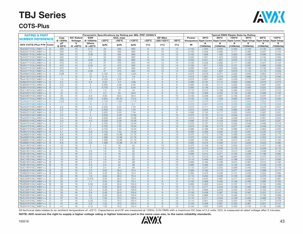
All technical data relates to an ambient temperature of +25°C. Capacitance and DF are measured at 120Hz, 0.5V RMS with a maximum DC bias of 2.2 volts. DCL is measured at rated voltage after 5 minutes.
NOTE: AVX reserves the right to supply a higher voltage rating or tighter tolerance part in the same case size, to the same reliability standards.
43100516
TBJ SeriesCOTS-Plus
Parametric Specifications by Rating per MIL-PRF-55365/4 Typical RMS Ripple Data by RatingCap DC Rated ESR DCL max DF Max Power 25ºC 85ºC 125ºC 25ºC 85ºC 125ºC
@ 120Hz Voltage @ 100kHz +25ºC +85ºC +125ºC +25ºC +(85/125)ºC -55ºC Dissipation Ripple Current Ripple Current Ripple Current Ripple Voltage Ripple Voltage Ripple Voltage
AVX COTS-Plus P/N CaseμF V Ohms
(μA) (μA) (μA) (%) (%) (%) WA A A V V V
@ 25ºC @ +85ºC @ +25ºC (100kHz) (100kHz) (100kHz) (100kHz) (100kHz) (100kHz)TBJD337*010L�#@0^++ D 330 10 0.15 33 330 660 8 10 12 0.150 1.000 0.900 0.400 0.150 0.135 0.060TBJE337*010C�#@0^++ E 330 10 0.9 33 330 660 8 10 12 0.165 0.428 0.385 0.171 0.385 0.347 0.154TBJE337*010L�#@0^++ E 330 10 0.06 33 330 660 8 10 12 0.165 1.658 1.492 0.663 0.099 0.090 0.040TBJV337*010C�#@0^++ V 330 10 0.1 33 330 660 8 10 12 0.250 1.581 1.423 0.632 0.158 0.142 0.063TBJV337*010L�#@0^++ V 330 10 0.06 33 330 660 10 10 12 0.250 2.041 1.837 0.816 0.122 0.110 0.049TBJE477*010C�#@0^++ E 470 10 0.9 47 470 940 10 12 14 0.165 0.428 0.385 0.171 0.385 0.347 0.154TBJE477*010L�#@0^++ E 470 10 0.05 47 470 940 10 12 14 0.165 1.817 1.635 0.727 0.091 0.082 0.036TBJV477*010C�#@0^++ V 470 10 0.1 47 470 940 10 12 14 0.250 1.581 1.423 0.632 0.158 0.142 0.063TBJV477*010L�#@0^++ V 470 10 0.06 47 470 940 10 12 14 0.250 2.041 1.837 0.816 0.122 0.110 0.049TBJA684*015C�#@0^++ A 0.68 15 12 0.102 1.02 1.224 4 6 6 0.075 0.079 0.071 0.032 0.949 0.854 0.379TBJA105*015C�#@0^++ A 1 15 10 0.15 1.5 1.8 4 6 6 0.075 0.087 0.078 0.035 0.866 0.779 0.346TBJA155*015C�#@0^++ A 1.5 15 8 0.225 2.25 2.7 6 9 9 0.075 0.097 0.087 0.039 0.775 0.697 0.310TBJB225*015C�#@0^++ B 2.2 15 5.5 0.33 3.3 3.96 6 9 9 0.085 0.124 0.112 0.050 0.684 0.615 0.273TBJB335*015C�#@0^++ B 3.3 15 5 0.495 4.95 5.94 6 8 9 0.085 0.130 0.117 0.052 0.652 0.587 0.261TBJB475*015C�#@0^++ B 4.7 15 4 0.705 7.05 8.46 6 8 8 0.085 0.146 0.131 0.058 0.583 0.525 0.233TBJC106*015C�#@0^++ C 10 15 2.5 1.5 15 18 6 8 9 0.110 0.210 0.189 0.084 0.524 0.472 0.210TBJD226*015C�#@0^++ D 22 15 1.1 3.3 33 39.6 6 8 9 0.150 0.369 0.332 0.148 0.406 0.366 0.162TBJD336*015C�#@0^++ D 33 15 0.9 4.95 49.5 59.4 6 8 10 0.150 0.408 0.367 0.163 0.367 0.331 0.147TBJD157*015L�#@0^++ D 150 15 0.05 5.625 56.25 112.5 6 9 10 0.150 1.732 1.559 0.693 0.087 0.078 0.035TBJA684*016C�#@0^++ A 0.68 16 12 0.109 1.088 2.176 4 6 6 0.075 0.079 0.071 0.032 0.949 0.854 0.379TBJA105*016C�#@0^++ A 1 16 10 0.16 1.6 3.2 4 6 6 0.075 0.087 0.078 0.035 0.866 0.779 0.346TBJA225*016C�#@0^++ A 2.2 16 5.5 0.352 3.52 7.04 6 9 10 0.075 0.117 0.105 0.047 0.642 0.578 0.257TBJA225*016L�#@0^++ A 2.2 16 1.8 0.352 3.52 7.04 6 9 10 0.075 0.204 0.184 0.082 0.367 0.331 0.147TBJB225*016C�#@0^++ B 2.2 16 5 0.352 3.52 7.04 6 8 8 0.085 0.130 0.117 0.052 0.652 0.587 0.261TBJA335*016C�#@0^++ A 3.3 16 5 0.528 5.28 10.56 6 9 10 0.075 0.122 0.110 0.049 0.612 0.551 0.245TBJA335*016L�#@0^++ A 3.3 16 3.5 0.528 5.28 10.56 6 9 10 0.075 0.146 0.132 0.059 0.512 0.461 0.205TBJB335*016C�#@0^++ B 3.3 16 4.5 0.528 5.28 10.56 6 9 10 0.085 0.137 0.124 0.055 0.618 0.557 0.247TBJA475*016C�#@0^++ A 4.7 16 4 0.752 7.52 15.04 6 9 10 0.075 0.137 0.123 0.055 0.548 0.493 0.219TBJA475*016L�#@0^++ A 4.7 16 2 0.752 7.52 15.04 6 9 10 0.075 0.194 0.174 0.077 0.387 0.349 0.155TBJB475*016C�#@0^++ B 4.7 16 3.1 0.752 7.52 15.04 6 8 8 0.085 0.166 0.149 0.066 0.513 0.462 0.205TBJB475*016L�#@0^++ B 4.7 16 0.8 0.752 7.52 15.04 6 9 10 0.085 0.326 0.293 0.130 0.261 0.235 0.104TBJA685*016C�#@0^++ A 6.8 16 2.5 1.088 10.88 21.76 6 9 10 0.075 0.173 0.156 0.069 0.433 0.390 0.173TBJA685*016L�#@0^++ A 6.8 16 1.5 1.088 10.88 21.76 6 9 10 0.075 0.224 0.201 0.089 0.335 0.302 0.134TBJB685*016C�#@0^++ B 6.8 16 2.5 1.088 10.88 21.76 6 9 10 0.085 0.184 0.166 0.074 0.461 0.415 0.184TBJB685*016L�#@0^++ B 6.8 16 0.6 1.088 10.88 21.76 6 9 10 0.085 0.376 0.339 0.151 0.226 0.203 0.090TBJA106*016C�#@0^++ A 10 16 3 1.6 16 32 8 10 12 0.075 0.158 0.142 0.063 0.474 0.427 0.190TBJA106*016L�#@0^++ A 10 16 1 1.6 16 32 8 10 12 0.075 0.274 0.246 0.110 0.274 0.246 0.110TBJB106*016C�#@0^++ B 10 16 2.8 1.6 16 32 6 9 10 0.085 0.174 0.157 0.070 0.488 0.439 0.195TBJB106*016L�#@0^++ B 10 16 0.5 1.6 16 32 6 9 10 0.085 0.412 0.371 0.165 0.206 0.186 0.082TBJC106*016C�#@0^++ C 10 16 2.5 1.6 16 32 6 8 10 0.110 0.210 0.189 0.084 0.524 0.472 0.210TBJC106*016L�#@0^++ C 10 16 0.5 1.6 16 32 6 9 10 0.110 0.469 0.422 0.188 0.235 0.211 0.094TBJB156*016C�#@0^++ B 15 16 2.5 2.4 24 48 6 9 10 0.085 0.184 0.166 0.074 0.461 0.415 0.184TBJB156*016L�#@0^++ B 15 16 0.8 2.4 24 48 6 9 10 0.085 0.326 0.293 0.130 0.261 0.235 0.104TBJC156*016C�#@0^++ C 15 16 1.8 2.4 24 48 6 9 10 0.110 0.247 0.222 0.099 0.445 0.400 0.178TBJB226*016C�#@0^++ B 22 16 2.3 3.52 35.2 70.4 6 9 10 0.085 0.192 0.173 0.077 0.442 0.398 0.177TBJB226*016L�#@0^++ B 22 16 0.6 3.52 35.2 70.4 6 9 10 0.085 0.376 0.339 0.151 0.226 0.203 0.090TBJC226*016C�#@0^++ C 22 16 1.6 3.52 35.2 70.4 6 9 10 0.110 0.262 0.236 0.105 0.420 0.378 0.168TBJC226*016L�#@0^++ C 22 16 0.375 3.52 35.2 70.4 6 9 10 0.110 0.542 0.487 0.217 0.203 0.183 0.081TBJD226*016C�#@0^++ D 22 16 1.1 3.52 35.2 70.4 6 8 9 0.150 0.369 0.332 0.148 0.406 0.366 0.162TBJB336*016L�#@0^++ B 33 16 0.35 5.28 52.8 105.6 8 10 12 0.085 0.493 0.444 0.197 0.172 0.155 0.069TBJC336*016C�#@0^++ C 33 16 1.5 5.28 52.8 105.6 6 9 10 0.110 0.271 0.244 0.108 0.406 0.366 0.162TBJC336*016L�#@0^++ C 33 16 0.3 5.28 52.8 105.6 6 9 10 0.110 0.606 0.545 0.242 0.182 0.163 0.073TBJD336*016C�#@0^++ D 33 16 0.9 5.28 52.8 105.6 6 9 10 0.150 0.408 0.367 0.163 0.367 0.331 0.147TBJD336*016L�#@0^++ D 33 16 0.2 5.28 52.8 105.6 6 9 10 0.150 0.866 0.779 0.346 0.173 0.156 0.069TBJC476*016C�#@0^++ C 47 16 1.5 7.52 75.2 150.4 6 9 10 0.110 0.271 0.244 0.108 0.406 0.366 0.162TBJC476*016L�#@0^++ C 47 16 0.35 7.52 75.2 150.4 6 9 10 0.110 0.561 0.505 0.224 0.196 0.177 0.078TBJD476*016C�#@0^++ D 47 16 0.9 7.52 75.2 150.4 6 9 10 0.150 0.408 0.367 0.163 0.367 0.331 0.147TBJD476*016L�#@0^++ D 47 16 0.15 7.52 75.2 150.4 6 9 10 0.150 1.000 0.900 0.400 0.150 0.135 0.060
RATING & PART NUMBER REFERENCE

Parametric Specifications by Rating per MIL-PRF-55365/4 Typical RMS Ripple Data by RatingCap DC Rated ESR DCL max DF Max Power 25ºC 85ºC 125ºC 25ºC 85ºC 125ºC
@ 120Hz Voltage @ 100kHz +25ºC +85ºC +125ºC +25ºC +(85/125)ºC -55ºC Dissipation Ripple Current Ripple Current Ripple Current Ripple Voltage Ripple Voltage Ripple Voltage
AVX COTS-Plus P/N CaseμF V Ohms
(μA) (μA) (μA) (%) (%) (%) WA A A V V V
@ 25ºC @ +85ºC @ +25ºC (100kHz) (100kHz) (100kHz) (100kHz) (100kHz) (100kHz)TBJC686*016C�#@0^++ C 68 16 0.2 10.88 108.8 217.6 6 9 10 0.110 0.742 0.667 0.297 0.148 0.133 0.059TBJC686*016L�#@0^++ C 68 16 0.125 10.88 108.8 217.6 6 9 10 0.110 0.938 0.844 0.375 0.117 0.106 0.047TBJD686*016C�#@0^++ D 68 16 0.9 10.88 108.8 217.6 6 9 10 0.150 0.408 0.367 0.163 0.367 0.331 0.147TBJD686*016L�#@0^++ D 68 16 0.07 10.88 108.8 217.6 6 9 10 0.150 1.464 1.317 0.586 0.102 0.092 0.041TBJD107*016C�#@0^++ D 100 16 0.9 16 160 320 6 9 10 0.150 0.408 0.367 0.163 0.367 0.331 0.147TBJD107*016L�#@0^++ D 100 16 0.125 16 160 320 6 9 10 0.150 1.095 0.986 0.438 0.137 0.123 0.055TBJE107*016C�#@0^++ E 100 16 0.9 16 160 320 6 9 10 0.165 0.428 0.385 0.171 0.385 0.347 0.154TBJE107*016L�#@0^++ E 100 16 0.1 16 160 320 6 9 10 0.165 1.285 1.156 0.514 0.128 0.116 0.051TBJD157*016C�#@0^++ D 150 16 0.9 24 240 480 6 9 10 0.150 0.408 0.367 0.163 0.367 0.331 0.147TBJD157*016L�#@0^++ D 150 16 0.15 24 240 480 6 9 10 0.150 1.000 0.900 0.400 0.150 0.135 0.060TBJE157*016C�#@0^++ E 150 16 0.3 24 240 480 6 9 10 0.165 0.742 0.667 0.297 0.222 0.200 0.089TBJE157*016L�#@0^++ E 150 16 0.1 24 240 480 6 9 10 0.165 1.285 1.156 0.514 0.128 0.116 0.051TBJV157*016C�#@0^++ V 150 16 0.075 24 240 480 8 10 12 0.250 1.826 1.643 0.730 0.137 0.123 0.055TBJV157*016L�#@0^++ V 150 16 0.045 24 240 480 6 8 10 0.250 2.357 2.121 0.943 0.106 0.095 0.042TBJE227*016C�#@0^++ E 220 16 0.15 35.2 352 704 10 12 14 0.165 1.049 0.944 0.420 0.157 0.142 0.063TBJE227*016L�#@0^++ E 220 16 0.1 35.2 352 704 10 12 14 0.165 1.285 1.156 0.514 0.128 0.116 0.051TBJV227*016C�#@0^++ V 220 16 0.15 35.2 352 704 8 10 12 0.250 1.291 1.162 0.516 0.194 0.174 0.077TBJV227*016L�#@0^++ V 220 16 0.075 35.2 352 704 8 10 12 0.250 1.826 1.643 0.730 0.137 0.123 0.055TBJA474*020C�#@0^++ A 0.47 20 14 0.5 5 10 4 6 6 0.075 0.073 0.066 0.029 1.025 0.922 0.410TBJA684*020C�#@0^++ A 0.68 20 12 0.136 1.36 1.632 4 6 6 0.075 0.079 0.071 0.032 0.949 0.854 0.379TBJA105*020C�#@0^++ A 1 20 10 0.2 2 2.4 4 6 6 0.075 0.087 0.078 0.035 0.866 0.779 0.346TBJA105*020L�#@0^++ A 1 20 3 0.2 2 4 4 6 6 0.075 0.158 0.142 0.063 0.474 0.427 0.190TBJA155*020C�#@0^++ A 1.5 20 6.5 0.3 3 6 4 8 10 0.075 0.107 0.097 0.043 0.698 0.628 0.279TBJB155*020C�#@0^++ B 1.5 20 6 0.3 3 3.6 6 9 9 0.085 0.119 0.107 0.048 0.714 0.643 0.286TBJA225*020C�#@0^++ A 2.2 20 5.3 0.44 4.4 8.8 6 8 8 0.075 0.158 0.142 0.063 0.474 0.427 0.190TBJA225*020L�#@0^++ A 2.2 20 3 0.44 4.4 8.8 6 9 10 0.075 0.158 0.142 0.063 0.474 0.427 0.190TBJB225*020C�#@0^++ B 2.2 20 5 0.44 4.4 5.28 6 8 9 0.085 0.130 0.117 0.052 0.652 0.587 0.261TBJA335*020L�#@0^++ A 3.3 20 2.5 0.66 6.6 13.2 6 9 10 0.075 0.173 0.156 0.069 0.433 0.390 0.173TBJB335*020C�#@0^++ B 3.3 20 4 0.66 6.6 7.92 6 9 9 0.085 0.146 0.131 0.058 0.583 0.525 0.233TBJB335*020L�#@0^++ B 3.3 20 1.3 0.66 6.6 13.2 6 9 10 0.085 0.256 0.230 0.102 0.332 0.299 0.133TBJA475*020C�#@0^++ A 4.7 20 4 0.94 9.4 18.8 6 8 10 0.075 0.137 0.123 0.055 0.548 0.493 0.219TBJA475*020L�#@0^++ A 4.7 20 1.8 0.94 9.4 18.8 6 8 10 0.075 0.204 0.184 0.082 0.367 0.331 0.147TBJB475*020C�#@0^++ B 4.7 20 3 0.94 9.4 18.8 6 8 10 0.085 0.168 0.151 0.067 0.505 0.454 0.202TBJB475*020L�#@0^++ B 4.7 20 0.75 0.94 9.4 18.8 6 9 10 0.085 0.337 0.303 0.135 0.252 0.227 0.101TBJC475*020C�#@0^++ C 4.7 20 3 0.94 9.4 11.28 6 8 9 0.110 0.191 0.172 0.077 0.574 0.517 0.230TBJA685*020L�#@0^++ A 6.8 20 1 1.36 13.6 27.2 6 9 10 0.075 0.274 0.246 0.110 0.274 0.246 0.110TBJB685*020C�#@0^++ B 6.8 20 2.5 1.36 13.6 27.2 6 8 10 0.085 0.184 0.166 0.074 0.461 0.415 0.184TBJB685*020L�#@0^++ B 6.8 20 0.6 1.36 13.6 27.2 6 9 10 0.085 0.376 0.339 0.151 0.226 0.203 0.090TBJC685*020C�#@0^++ C 6.8 20 2.4 1.36 13.6 16.32 6 9 9 0.110 0.214 0.193 0.086 0.514 0.462 0.206TBJC685*020L�#@0^++ C 6.8 20 0.7 1.36 13.6 27.2 6 9 10 0.110 0.396 0.357 0.159 0.277 0.250 0.111TBJB106*020C�#@0^++ B 10 20 2.1 2 20 40 6 8 10 0.085 0.201 0.181 0.080 0.422 0.380 0.169TBJB106*020L�#@0^++ B 10 20 1 2 20 40 6 8 10 0.085 0.292 0.262 0.117 0.292 0.262 0.117TBJC106*020C�#@0^++ C 10 20 1.9 2 20 40 6 8 10 0.110 0.241 0.217 0.096 0.457 0.411 0.183TBJC106*020L�#@0^++ C 10 20 0.5 2 20 40 6 9 10 0.110 0.469 0.422 0.188 0.235 0.211 0.094TBJB156*020C�#@0^++ B 15 20 2 3 30 60 6 8 10 0.085 0.206 0.186 0.082 0.412 0.371 0.165TBJB156*020L�#@0^++ B 15 20 0.5 3 30 60 6 9 10 0.085 0.412 0.371 0.165 0.206 0.186 0.082TBJC156*020C�#@0^++ C 15 20 1.7 3 30 60 6 8 10 0.110 0.254 0.229 0.102 0.432 0.389 0.173TBJC156*020L�#@0^++ C 15 20 0.4 3 30 60 6 8 10 0.110 0.524 0.472 0.210 0.210 0.189 0.084TBJD156*020C�#@0^++ D 15 20 1.1 3 30 36 6 8 9 0.150 0.369 0.332 0.148 0.406 0.366 0.162TBJB226*020C�#@0^++ B 22 20 0.6 4.4 44 88 6 9 10 0.085 0.376 0.339 0.151 0.226 0.203 0.090TBJB226*020L�#@0^++ B 22 20 0.4 4.4 44 88 6 9 10 0.085 0.461 0.415 0.184 0.184 0.166 0.074TBJC226*020C�#@0^++ C 22 20 1.6 4.4 44 88 6 8 10 0.110 0.262 0.236 0.105 0.420 0.378 0.168TBJC226*020L�#@0^++ C 22 20 0.15 4.4 44 88 6 8 10 0.110 0.856 0.771 0.343 0.128 0.116 0.051TBJD226*020C�#@0^++ D 22 20 0.9 4.4 44 52.8 6 9 9 0.150 0.408 0.367 0.163 0.367 0.331 0.147TBJD226*020L�#@0^++ D 22 20 0.2 4.4 44 88 6 9 10 0.150 0.866 0.779 0.346 0.173 0.156 0.069TBJC336*020C�#@0^++ C 33 20 1.5 6.6 66 132 6 8 10 0.110 0.271 0.244 0.108 0.406 0.366 0.162
RATING & PART NUMBER REFERENCE
All technical data relates to an ambient temperature of +25°C. Capacitance and DF are measured at 120Hz, 0.5V RMS with a maximum DC bias of 2.2 volts. DCL is measured at rated voltage after 5 minutes.
NOTE: AVX reserves the right to supply a higher voltage rating or tighter tolerance part in the same case size, to the same reliability standards.
44 100516
TBJ SeriesCOTS-Plus

Parametric Specifications by Rating per MIL-PRF-55365/4 Typical RMS Ripple Data by RatingCap DC Rated ESR DCL max DF Max Power 25ºC 85ºC 125ºC 25ºC 85ºC 125ºC
@ 120Hz Voltage @ 100kHz +25ºC +85ºC +125ºC +25ºC +(85/125)ºC -55ºC Dissipation Ripple Current Ripple Current Ripple Current Ripple Voltage Ripple Voltage Ripple Voltage
AVX COTS-Plus P/N CaseμF V Ohms
(μA) (μA) (μA) (%) (%) (%) WA A A V V V
@ 25ºC @ +85ºC @ +25ºC (100kHz) (100kHz) (100kHz) (100kHz) (100kHz) (100kHz)TBJC336*020L�#@0^++ C 33 20 0.3 6.6 66 132 6 9 10 0.110 0.606 0.545 0.242 0.182 0.163 0.073TBJD336*020C�#@0^++ D 33 20 0.9 6.6 66 132 6 8 10 0.150 0.408 0.367 0.163 0.367 0.331 0.147TBJD336*020L�#@0^++ D 33 20 0.1 6.6 66 132 6 8 10 0.150 1.225 1.102 0.490 0.122 0.110 0.049TBJD476*020C�#@0^++ D 47 20 0.2 9.4 94 188 6 8 10 0.150 0.866 0.779 0.346 0.173 0.156 0.069TBJD476*020L�#@0^++ D 47 20 0.1 9.4 94 188 6 8 10 0.150 1.225 1.102 0.490 0.122 0.110 0.049TBJE476*020C�#@0^++ E 47 20 0.25 9.4 94 188 6 8 8 0.165 0.812 0.731 0.325 0.203 0.183 0.081TBJE476*020L�#@0^++ E 47 20 0.07 9.4 94 188 6 9 10 0.165 1.535 1.382 0.614 0.107 0.097 0.043TBJD686*020C�#@0^++ D 68 20 0.9 13.6 136 272 6 8 10 0.150 0.408 0.367 0.163 0.367 0.331 0.147TBJD686*020L�#@0^++ D 68 20 0.07 13.6 136 272 6 9 10 0.150 1.464 1.317 0.586 0.102 0.092 0.041TBJE686*020C�#@0^++ E 68 20 0.9 13.6 136 272 6 8 10 0.165 0.428 0.385 0.171 0.385 0.347 0.154TBJE686*020L�#@0^++ E 68 20 0.15 13.6 136 272 6 8 10 0.165 1.049 0.944 0.420 0.157 0.142 0.063TBJD107*020C�#@0^++ D 100 20 0.1 20 200 400 6 9 10 0.150 1.225 1.102 0.490 0.122 0.110 0.049TBJD107*020L�#@0^++ D 100 20 0.085 20 200 400 6 9 10 0.150 1.328 1.196 0.531 0.113 0.102 0.045TBJE107*020C�#@0^++ E 100 20 0.15 20 200 400 6 9 10 0.165 1.049 0.944 0.420 0.157 0.142 0.063TBJE107*020L�#@0^++ E 100 20 0.1 20 200 400 6 9 10 0.165 1.285 1.156 0.514 0.128 0.116 0.051TBJV107*020C�#@0^++ V 100 20 0.2 20 200 400 8 10 12 0.250 1.118 1.006 0.447 0.224 0.201 0.089TBJV107*020L�#@0^++ V 100 20 0.085 20 200 400 8 10 12 0.250 1.715 1.543 0.686 0.146 0.131 0.058TBJE157*020C�#@0^++ E 150 20 0.3 30 300 600 8 10 10 0.165 0.742 0.667 0.297 0.222 0.200 0.089TBJV157*020L�#@0^++ V 150 20 0.08 30 300 600 8 10 12 0.250 1.768 1.591 0.707 0.141 0.127 0.057TBJA334*025C�#@0^++ A 0.33 25 15 0.083 0.825 0.99 4 6 6 0.075 0.071 0.064 0.028 1.061 0.955 0.424TBJA474*025C�#@0^++ A 0.47 25 14 0.118 1.175 1.41 4 6 6 0.075 0.073 0.066 0.029 1.025 0.922 0.410TBJA474*025L�#@0^++ A 0.47 25 7 0.118 1.175 2.35 4 6 6 0.075 0.104 0.093 0.041 0.725 0.652 0.290TBJA684*025C�#@0^++ A 0.68 25 10 0.68 6.8 13.6 4 6 8 0.075 0.087 0.078 0.035 0.866 0.779 0.346TBJA684*025L�#@0^++ A 0.68 25 6 0.17 1.7 3.4 4 6 6 0.075 0.112 0.101 0.045 0.671 0.604 0.268TBJB684*025C�#@0^++ B 0.68 25 7.5 0.17 1.7 2.04 4 6 6 0.085 0.106 0.096 0.043 0.798 0.719 0.319TBJA105*025C�#@0^++ A 1 25 8 0.25 2.5 5 4 6 8 0.075 0.097 0.087 0.039 0.775 0.697 0.310TBJB105*025C�#@0^++ B 1 25 6.5 0.25 2.5 3 4 6 6 0.085 0.114 0.103 0.046 0.743 0.669 0.297TBJA155*025C�#@0^++ A 1.5 25 7.5 0.375 3.75 7.5 6 8 10 0.075 0.100 0.090 0.040 0.750 0.675 0.300TBJA155*025L�#@0^++ A 1.5 25 3 0.375 3.75 7.5 6 8 10 0.075 0.158 0.142 0.063 0.474 0.427 0.190TBJB155*025C�#@0^++ B 1.5 25 6.5 0.375 3.75 4.5 6 8 9 0.085 0.114 0.103 0.046 0.743 0.669 0.297TBJB155*025L�#@0^++ B 1.5 25 1.8 0.375 3.75 7.5 6 9 10 0.085 0.217 0.196 0.087 0.391 0.352 0.156TBJB225*025C�#@0^++ B 2.2 25 4.5 0.55 5.5 11 6 8 10 0.085 0.137 0.124 0.055 0.618 0.557 0.247TBJB225*025L�#@0^++ B 2.2 25 0.9 0.55 5.5 11 6 9 10 0.085 0.307 0.277 0.123 0.277 0.249 0.111TBJC225*025C�#@0^++ C 2.2 25 3.5 0.55 5.5 6.6 6 9 9 0.110 0.177 0.160 0.071 0.620 0.558 0.248TBJA335*025C�#@0^++ A 3.3 25 1.5 0.825 8.25 16.5 6 9 10 0.075 0.224 0.201 0.089 0.335 0.302 0.134TBJA335*025L�#@0^++ A 3.3 25 1 0.825 8.25 16.5 6 9 10 0.075 0.274 0.246 0.110 0.274 0.246 0.110TBJB335*025C�#@0^++ B 3.3 25 3.5 0.825 8.25 16.5 6 8 10 0.085 0.156 0.140 0.062 0.545 0.491 0.218TBJB335*025L�#@0^++ B 3.3 25 0.75 0.825 8.25 16.5 6 9 10 0.085 0.337 0.303 0.135 0.252 0.227 0.101TBJC335*025C�#@0^++ C 3.3 25 3.5 0.825 8.25 9.9 6 8 9 0.110 0.177 0.160 0.071 0.620 0.558 0.248TBJA475*025C�#@0^++ A 4.7 25 2.8 1.175 11.75 23.5 6 9 10 0.075 0.164 0.147 0.065 0.458 0.412 0.183TBJB475*025C�#@0^++ B 4.7 25 2.8 1.175 11.75 23.5 6 8 10 0.085 0.174 0.157 0.070 0.488 0.439 0.195TBJB475*025L�#@0^++ B 4.7 25 1.5 1.175 11.75 23.5 6 8 10 0.085 0.238 0.214 0.095 0.357 0.321 0.143TBJC475*025C�#@0^++ C 4.7 25 2.5 1.175 11.75 14.1 6 9 9 0.110 0.210 0.189 0.084 0.524 0.472 0.210TBJB685*025C�#@0^++ B 6.8 25 2.8 1.7 17 34 6 8 10 0.085 0.174 0.157 0.070 0.488 0.439 0.195TBJB685*025L�#@0^++ B 6.8 25 0.7 1.7 17 34 6 9 10 0.085 0.348 0.314 0.139 0.244 0.220 0.098TBJC685*025C�#@0^++ C 6.8 25 2 1.7 17 34 6 8 10 0.110 0.235 0.211 0.094 0.469 0.422 0.188TBJC685*025L�#@0^++ C 6.8 25 0.5 1.7 17 34 6 9 10 0.110 0.469 0.422 0.188 0.235 0.211 0.094TBJD685*025C�#@0^++ D 6.8 25 1.4 1.7 17 20.4 6 9 9 0.150 0.327 0.295 0.131 0.458 0.412 0.183TBJC106*025C�#@0^++ C 10 25 1.8 2.5 25 50 6 8 10 0.110 0.247 0.222 0.099 0.445 0.400 0.178TBJC106*025L�#@0^++ C 10 25 0.5 2.5 25 50 6 8 10 0.110 0.469 0.422 0.188 0.235 0.211 0.094TBJD106*025C�#@0^++ D 10 25 1.2 2.5 25 30 6 8 9 0.150 0.354 0.318 0.141 0.424 0.382 0.170TBJC156*025C�#@0^++ C 15 25 0.3 3.75 37.5 75 6 9 10 0.110 0.606 0.545 0.242 0.182 0.163 0.073TBJC156*025L�#@0^++ C 15 25 0.22 3.75 37.5 75 6 9 10 0.110 0.707 0.636 0.283 0.156 0.140 0.062TBJD156*025C�#@0^++ D 15 25 1 3.75 37.5 45 6 9 9 0.150 0.387 0.349 0.155 0.387 0.349 0.155TBJD156*025L�#@0^++ D 15 25 0.3 3.75 37.5 75 6 8 9 0.150 0.707 0.636 0.283 0.212 0.191 0.085TBJC226*025C�#@0^++ C 22 25 1.4 5.5 55 110 6 8 10 0.110 0.280 0.252 0.112 0.392 0.353 0.157
RATING & PART NUMBER REFERENCE
All technical data relates to an ambient temperature of +25°C. Capacitance and DF are measured at 120Hz, 0.5V RMS with a maximum DC bias of 2.2 volts. DCL is measured at rated voltage after 5 minutes.
NOTE: AVX reserves the right to supply a higher voltage rating or tighter tolerance part in the same case size, to the same reliability standards.
45100516
TBJ SeriesCOTS-Plus

Parametric Specifications by Rating per MIL-PRF-55365/4 Typical RMS Ripple Data by RatingCap DC Rated ESR DCL max DF Max Power 25ºC 85ºC 125ºC 25ºC 85ºC 125ºC
@ 120Hz Voltage @ 100kHz +25ºC +85ºC +125ºC +25ºC +(85/125)ºC -55ºC Dissipation Ripple Current Ripple Current Ripple Current Ripple Voltage Ripple Voltage Ripple Voltage
AVX COTS-Plus P/N CaseμF V Ohms
(μA) (μA) (μA) (%) (%) (%) WA A A V V V
@ 25ºC @ +85ºC @ +25ºC (100kHz) (100kHz) (100kHz) (100kHz) (100kHz) (100kHz)TBJC226*025L�#@0^++ C 22 25 0.275 5.5 55 110 6 8 10 0.110 0.632 0.569 0.253 0.174 0.157 0.070TBJD226*025C�#@0^++ D 22 25 0.9 5.5 55 110 6 8 10 0.150 0.408 0.367 0.163 0.367 0.331 0.147TBJD226*025L�#@0^++ D 22 25 0.2 5.5 55 110 6 8 10 0.150 0.866 0.779 0.346 0.173 0.156 0.069TBJD336*025C�#@0^++ D 33 25 0.9 8.25 82.5 165 6 8 10 0.150 0.408 0.367 0.163 0.367 0.331 0.147TBJD336*025L�#@0^++ D 33 25 0.1 8.25 82.5 165 6 8 10 0.150 1.225 1.102 0.490 0.122 0.110 0.049TBJE336*025C�#@0^++ E 33 25 0.9 8.25 82.5 165 6 8 10 0.165 0.428 0.385 0.171 0.385 0.347 0.154TBJE336*025L�#@0^++ E 33 25 0.3 8.25 82.5 165 6 8 10 0.165 0.742 0.667 0.297 0.222 0.200 0.089TBJD476*025C�#@0^++ D 47 25 0.9 11.75 117.5 235 6 8 10 0.150 0.408 0.367 0.163 0.367 0.331 0.147TBJD476*025L�#@0^++ D 47 25 0.25 11.75 117.5 235 6 8 10 0.150 0.775 0.697 0.310 0.194 0.174 0.077TBJE476*025C�#@0^++ E 47 25 0.1 11.75 117.5 235 6 9 10 0.165 1.285 1.156 0.514 0.128 0.116 0.051TBJE476*025L�#@0^++ E 47 25 0.08 11.75 117.5 235 6 9 10 0.165 1.436 1.293 0.574 0.115 0.103 0.046TBJE686*025C�#@0^++ E 68 25 0.2 17 170 340 6 9 10 0.165 0.908 0.817 0.363 0.182 0.163 0.073TBJE686*025L�#@0^++ E 68 25 0.125 17 170 340 6 9 10 0.165 1.149 1.034 0.460 0.144 0.129 0.057TBJV686*025L�#@0^++ V 68 25 0.095 17 170 340 6 9 10 0.250 1.622 1.460 0.649 0.154 0.139 0.062TBJV107*025L�#@0^++ V 100 25 0.1 25 250 500 8 10 12 0.250 1.581 1.423 0.632 0.158 0.142 0.063TBJA104*035C�#@0^++ A 0.1 35 24 0.035 0.35 0.42 4 6 6 0.075 0.056 0.050 0.022 1.342 1.207 0.537TBJA154*035C�#@0^++ A 0.15 35 21 0.5 5 10 4 6 6 0.075 0.060 0.054 0.024 1.255 1.129 0.502TBJA224*035C�#@0^++ A 0.22 35 18 0.5 5 10 4 6 6 0.075 0.065 0.058 0.026 1.162 1.046 0.465TBJA224*035L�#@0^++ A 0.22 35 6 0.077 0.77 1.54 4 6 6 0.075 0.112 0.101 0.045 0.671 0.604 0.268TBJA334*035C�#@0^++ A 0.33 35 15 0.5 5 10 4 6 6 0.075 0.071 0.064 0.028 1.061 0.955 0.424TBJA334*035L�#@0^++ A 0.33 35 6 0.116 1.155 2.31 4 6 6 0.075 0.112 0.101 0.045 0.671 0.604 0.268TBJA474*035C�#@0^++ A 0.47 35 12 0.165 1.645 3.29 4 6 8 0.075 0.079 0.071 0.032 0.949 0.854 0.379TBJA474*035L�#@0^++ A 0.47 35 6 0.165 1.645 3.29 4 6 6 0.075 0.112 0.101 0.045 0.671 0.604 0.268TBJB474*035C�#@0^++ B 0.47 35 10 0.165 1.645 1.974 4 6 6 0.085 0.092 0.083 0.037 0.922 0.830 0.369TBJB474*035L�#@0^++ B 0.47 35 4 0.165 1.645 3.29 4 6 6 0.085 0.146 0.131 0.058 0.583 0.525 0.233TBJA684*035C�#@0^++ A 0.68 35 8 0.238 2.38 4.76 4 6 8 0.075 0.097 0.087 0.039 0.775 0.697 0.310TBJA684*035L�#@0^++ A 0.68 35 6 0.238 2.38 4.76 4 6 6 0.075 0.112 0.101 0.045 0.671 0.604 0.268TBJB684*035C�#@0^++ B 0.68 35 8 0.238 2.38 2.856 4 6 6 0.085 0.103 0.093 0.041 0.825 0.742 0.330TBJA105*035C�#@0^++ A 1 35 7.5 0.35 3.5 7 4 6 6 0.075 0.100 0.090 0.040 0.750 0.675 0.300TBJA105*035L�#@0^++ A 1 35 3 0.35 3.5 7 4 6 6 0.075 0.158 0.142 0.063 0.474 0.427 0.190TBJB105*035C�#@0^++ B 1 35 6.5 0.35 3.5 4.2 4 6 6 0.085 0.114 0.103 0.046 0.743 0.669 0.297TBJB105*035L�#@0^++ B 1 35 2 0.35 3.5 7 4 6 6 0.085 0.206 0.186 0.082 0.412 0.371 0.165TBJA155*035C�#@0^++ A 1.5 35 7.5 0.525 5.25 10.5 6 8 9 0.075 0.100 0.090 0.040 0.750 0.675 0.300TBJB155*035C�#@0^++ B 1.5 35 5.2 0.525 5.25 10.5 6 8 9 0.085 0.128 0.115 0.051 0.665 0.598 0.266TBJB155*035L�#@0^++ B 1.5 35 2.5 0.525 5.25 10.5 6 9 10 0.085 0.184 0.166 0.074 0.461 0.415 0.184TBJC155*035C�#@0^++ C 1.5 35 4.5 0.525 5.25 6.3 6 8 9 0.110 0.156 0.141 0.063 0.704 0.633 0.281TBJA225*035C�#@0^++ A 2.2 35 4.5 0.77 7.7 15.4 6 9 9 0.075 0.129 0.116 0.052 0.581 0.523 0.232TBJA225*035L�#@0^++ A 2.2 35 1.5 0.77 7.7 15.4 6 9 10 0.075 0.224 0.201 0.089 0.335 0.302 0.134TBJB225*035C�#@0^++ B 2.2 35 4.2 0.77 7.7 15.4 6 8 9 0.085 0.142 0.128 0.057 0.597 0.538 0.239TBJB225*035L�#@0^++ B 2.2 35 2 0.77 7.7 15.4 6 8 9 0.085 0.206 0.186 0.082 0.412 0.371 0.165TBJC225*035C�#@0^++ C 2.2 35 3.5 0.77 7.7 9.24 6 8 9 0.110 0.177 0.160 0.071 0.620 0.558 0.248TBJC225*035L�#@0^++ C 2.2 35 1 0.77 7.7 15.4 6 9 10 0.110 0.332 0.298 0.133 0.332 0.298 0.133TBJB335*035C�#@0^++ B 3.3 35 3.5 1.155 11.55 23.1 6 8 9 0.085 0.156 0.140 0.062 0.545 0.491 0.218TBJB335*035L�#@0^++ B 3.3 35 1 1.155 11.55 23.1 6 9 10 0.085 0.292 0.262 0.117 0.292 0.262 0.117TBJC335*035C�#@0^++ C 3.3 35 2.5 1.155 11.55 13.86 6 8 9 0.110 0.210 0.189 0.084 0.524 0.472 0.210TBJC335*035L�#@0^++ C 3.3 35 0.7 1.155 11.55 23.1 6 9 10 0.110 0.396 0.357 0.159 0.277 0.250 0.111TBJB475*035C�#@0^++ B 4.7 35 3.1 1.645 16.45 32.9 6 8 9 0.085 0.166 0.149 0.066 0.513 0.462 0.205TBJB475*035L�#@0^++ B 4.7 35 0.7 1.645 16.45 32.9 6 8 8 0.085 0.348 0.314 0.139 0.244 0.220 0.098TBJC475*035C�#@0^++ C 4.7 35 2.2 1.645 16.45 32.9 6 8 9 0.110 0.224 0.201 0.089 0.492 0.443 0.197TBJC475*035L�#@0^++ C 4.7 35 0.6 1.645 16.45 32.9 6 8 9 0.110 0.428 0.385 0.171 0.257 0.231 0.103TBJD475*035C�#@0^++ D 4.7 35 1.5 1.645 16.45 19.74 6 8 9 0.150 0.316 0.285 0.126 0.474 0.427 0.190TBJD475*035L�#@0^++ D 4.7 35 0.5 1.645 16.45 32.9 6 8 9 0.150 0.548 0.493 0.219 0.274 0.246 0.110TBJC685*035C�#@0^++ C 6.8 35 1.8 2.38 23.8 47.6 6 9 9 0.110 0.247 0.222 0.099 0.445 0.400 0.178TBJC685*035L�#@0^++ C 6.8 35 0.35 2.38 23.8 47.6 6 9 10 0.110 0.561 0.505 0.224 0.196 0.177 0.078
RATING & PART NUMBER REFERENCE
All technical data relates to an ambient temperature of +25°C. Capacitance and DF are measured at 120Hz, 0.5V RMS with a maximum DC bias of 2.2 volts. DCL is measured at rated voltage after 5 minutes.
NOTE: AVX reserves the right to supply a higher voltage rating or tighter tolerance part in the same case size, to the same reliability standards.
46 100516
TBJ SeriesCOTS-Plus

Parametric Specifications by Rating per MIL-PRF-55365/4 Typical RMS Ripple Data by RatingCap DC Rated ESR DCL max DF Max Power 25ºC 85ºC 125ºC 25ºC 85ºC 125ºC
@ 120Hz Voltage @ 100kHz +25ºC +85ºC +125ºC +25ºC +(85/125)ºC -55ºC Dissipation Ripple Current Ripple Current Ripple Current Ripple Voltage Ripple Voltage Ripple Voltage
AVX COTS-Plus P/N CaseμF V Ohms
(μA) (μA) (μA) (%) (%) (%) WA A A V V V
@ 25ºC @ +85ºC @ +25ºC (100kHz) (100kHz) (100kHz) (100kHz) (100kHz) (100kHz)TBJD685*035C�#@0^++ D 6.8 35 1.3 2.38 23.8 28.56 6 9 9 0.150 0.340 0.306 0.136 0.442 0.397 0.177TBJD685*035L�#@0^++ D 6.8 35 0.5 2.38 23.8 47.6 6 9 9 0.150 0.548 0.493 0.219 0.274 0.246 0.110TBJC106*035C�#@0^++ C 10 35 1.6 3.5 35 70 6 9 9 0.110 0.262 0.236 0.105 0.420 0.378 0.168TBJC106*035L�#@0^++ C 10 35 0.6 3.5 35 70 6 9 9 0.110 0.428 0.385 0.171 0.257 0.231 0.103TBJD106*035C�#@0^++ D 10 35 1 3.5 35 70 6 9 9 0.150 0.387 0.349 0.155 0.387 0.349 0.155TBJD106*035L�#@0^++ D 10 35 0.3 3.5 35 70 6 9 9 0.150 0.707 0.636 0.283 0.212 0.191 0.085TBJE106*035C�#@0^++ E 10 35 0.25 3.5 35 70 6 9 10 0.165 0.812 0.731 0.325 0.203 0.183 0.081TBJE106*035L�#@0^++ E 10 35 0.2 3.5 35 70 6 9 10 0.165 0.908 0.817 0.363 0.182 0.163 0.073TBJC156*035C�#@0^++ C 15 35 1.4 5.25 52.5 105 6 9 9 0.110 0.280 0.252 0.112 0.392 0.353 0.157TBJC156*035L�#@0^++ C 15 35 0.35 5.25 52.5 105 6 9 10 0.110 0.561 0.505 0.224 0.196 0.177 0.078TBJD156*035C�#@0^++ D 15 35 0.9 5.25 52.5 105 6 9 9 0.150 0.408 0.367 0.163 0.367 0.331 0.147TBJD156*035L�#@0^++ D 15 35 0.3 5.25 52.5 105 6 9 9 0.150 0.707 0.636 0.283 0.212 0.191 0.085TBJD226*035C�#@0^++ D 22 35 0.9 7.7 77 154 6 9 9 0.150 0.408 0.367 0.163 0.367 0.331 0.147TBJD226*035L�#@0^++ D 22 35 0.4 7.7 77 154 6 9 9 0.150 0.612 0.551 0.245 0.245 0.220 0.098TBJE226*035C�#@0^++ E 22 35 0.9 7.7 77 154 6 9 9 0.165 0.428 0.385 0.171 0.385 0.347 0.154TBJE226*035L�#@0^++ E 22 35 0.3 7.7 77 154 6 9 9 0.165 0.742 0.667 0.297 0.222 0.200 0.089TBJD336*035C�#@0^++ D 33 35 0.9 11.55 115.5 231 6 9 9 0.150 0.408 0.367 0.163 0.367 0.331 0.147TBJD336*035L�#@0^++ D 33 35 0.3 11.55 115.5 231 6 9 9 0.150 0.707 0.636 0.283 0.212 0.191 0.085TBJE336*035C�#@0^++ E 33 35 0.25 11.55 115.5 231 6 9 10 0.165 0.812 0.731 0.325 0.203 0.183 0.081TBJE336*035L�#@0^++ E 33 35 0.1 11.55 115.5 231 6 8 10 0.165 1.285 1.156 0.514 0.128 0.116 0.051TBJV336*035L�#@0^++ V 33 35 0.2 11.55 115.5 231 6 9 10 0.250 1.118 1.006 0.447 0.224 0.201 0.089TBJE476*035C�#@0^++ E 47 35 0.25 16.45 164.5 329 6 8 10 0.165 0.812 0.731 0.325 0.203 0.183 0.081TBJE476*035L�#@0^++ E 47 35 0.2 16.45 164.5 329 6 9 9 0.165 0.908 0.817 0.363 0.182 0.163 0.073TBJV476*035C�#@0^++ V 47 35 0.4 16.45 164.5 329 6 9 10 0.250 0.791 0.712 0.316 0.316 0.285 0.126TBJV476*035L�#@0^++ V 47 35 0.2 16.45 164.5 329 6 10 10 0.250 1.118 1.006 0.447 0.224 0.201 0.089TBJV686*035C�#@0^++ V 68 35 0.2 23.8 238 476 6 9 10 0.250 1.118 1.006 0.447 0.224 0.201 0.089TBJV686*035L�#@0^++ V 68 35 0.15 23.8 238 476 6 9 10 0.250 1.291 1.162 0.516 0.194 0.174 0.077TBJA104*050C�#@0^++ A 0.1 50 22 0.05 0.5 0.6 6 8 8 0.075 0.058 0.053 0.023 1.285 1.156 0.514TBJA154*050C�#@0^++ A 0.15 50 21 0.02 0.2 0.4 4 6 6 0.075 0.060 0.054 0.024 1.255 1.129 0.502TBJA154*050L�#@0^++ A 0.15 50 9 0.075 0.75 1.5 4 6 6 0.075 0.091 0.082 0.037 0.822 0.739 0.329TBJB154*050C�#@0^++ B 0.15 50 17 0.075 0.75 0.9 4 6 6 0.085 0.071 0.064 0.028 1.202 1.082 0.481TBJA224*050C�#@0^++ A 0.22 50 18 0.11 1.1 2.2 4 6 6 0.075 0.065 0.058 0.026 1.162 1.046 0.465TBJA224*050L�#@0^++ A 0.22 50 7 0.11 1.1 2.2 4 6 6 0.075 0.104 0.093 0.041 0.725 0.652 0.290TBJB224*050C�#@0^++ B 0.22 50 14 0.11 1.1 1.32 4 6 6 0.085 0.078 0.070 0.031 1.091 0.982 0.436TBJB334*050C�#@0^++ B 0.33 50 12 0.165 1.65 1.98 4 6 6 0.085 0.084 0.076 0.034 1.010 0.909 0.404TBJC474*050C�#@0^++ C 0.47 50 8 0.235 2.35 2.82 4 6 6 0.110 0.117 0.106 0.047 0.938 0.844 0.375TBJA684*050C�#@0^++ A 0.68 50 7.9 0.34 3.4 6.8 4 6 8 0.075 0.097 0.088 0.039 0.770 0.693 0.308TBJC684*050C�#@0^++ C 0.68 50 7 0.34 3.4 4.08 4 6 6 0.110 0.125 0.113 0.050 0.877 0.790 0.351TBJC105*050C�#@0^++ C 1 50 6 0.5 5 6 4 6 6 0.110 0.135 0.122 0.054 0.812 0.731 0.325TBJC105*050L�#@0^++ C 1 50 2.5 0.5 5 10 4 6 6 0.110 0.210 0.189 0.084 0.524 0.472 0.210TBJC155*050C�#@0^++ C 1.5 50 5 0.75 7.5 15 6 8 9 0.110 0.148 0.133 0.059 0.742 0.667 0.297TBJC155*050L�#@0^++ C 1.5 50 1.5 0.75 7.5 15 6 9 10 0.110 0.271 0.244 0.108 0.406 0.366 0.162TBJD155*050C�#@0^++ D 1.5 50 4 0.75 7.5 9 6 8 9 0.150 0.194 0.174 0.077 0.775 0.697 0.310TBJD225*050C�#@0^++ D 2.2 50 2.5 1.1 11 13.2 6 8 9 0.150 0.245 0.220 0.098 0.612 0.551 0.245TBJD225*050L�#@0^++ D 2.2 50 1.2 1.1 11 22 6 9 10 0.150 0.354 0.318 0.141 0.424 0.382 0.170TBJD335*050C�#@0^++ D 3.3 50 2 1.65 16.5 19.8 6 9 9 0.150 0.274 0.246 0.110 0.548 0.493 0.219TBJD335*050L�#@0^++ D 3.3 50 0.8 1.65 16.5 33 6 9 10 0.150 0.433 0.390 0.173 0.346 0.312 0.139TBJD475*050C�#@0^++ D 4.7 50 1.5 2.35 23.5 28.2 6 9 9 0.150 0.316 0.285 0.126 0.474 0.427 0.190TBJD475*050L�#@0^++ D 4.7 50 0.3 2.35 23.5 47 6 9 9 0.150 0.707 0.636 0.283 0.212 0.191 0.085TBJD685*050C�#@0^++ D 6.8 50 1 3.4 34 68 6 9 9 0.150 0.387 0.349 0.155 0.387 0.349 0.155TBJD685*050L�#@0^++ D 6.8 50 0.5 3.4 34 68 6 9 9 0.150 0.548 0.493 0.219 0.274 0.246 0.110TBJE106*050C�#@0^++ E 10 50 0.5 5 50 100 6 9 10 0.165 0.574 0.517 0.230 0.287 0.259 0.115TBJE106*050L�#@0^++ E 10 50 0.4 5 50 100 6 9 10 0.165 0.642 0.578 0.257 0.257 0.231 0.103
RATING & PART NUMBER REFERENCE
All technical data relates to an ambient temperature of +25°C. Capacitance and DF are measured at 120Hz, 0.5V RMS with a maximum DC bias of 2.2 volts. DCL is measured at rated voltage after 5 minutes.
NOTE: AVX reserves the right to supply a higher voltage rating or tighter tolerance part in the same case size, to the same reliability standards.
47100516
TBJ SeriesCOTS-Plus
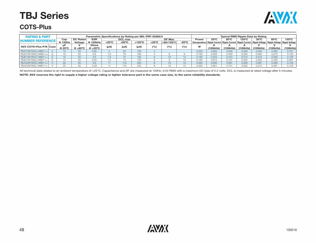
48 100516
TBJ SeriesCOTS-Plus
Parametric Specifications by Rating per MIL-PRF-55365/4 Typical RMS Ripple Data by RatingCap DC Rated ESR DCL max DF Max Power 25ºC 85ºC 125ºC 25ºC 85ºC 125ºC
@ 120Hz Voltage @ 100kHz +25ºC +85ºC +125ºC +25ºC +(85/125)ºC -55ºC Dissipation Ripple Current Ripple Current Ripple Current Ripple Voltage Ripple Voltage Ripple Voltage
AVX COTS-Plus P/N CaseμF V Ohms
(μA) (μA) (μA) (%) (%) (%) WA A A V V V
@ 25ºC @ +85ºC @ +25ºC (100kHz) (100kHz) (100kHz) (100kHz) (100kHz) (100kHz)TBJV106*050C�#@0^++ V 10 50 0.65 5 50 100 3 0.250 0.620 0.558 0.248 0.403 0.363 0.161TBJD156*050C�#@0^++ D 15 50 0.6 7.5 75 150 4 6 6 0.150 0.500 0.450 0.200 0.300 0.270 0.120TBJE156*050C�#@0^++ E 15 50 0.6 7.5 75 150 8 10 12 0.165 0.524 0.472 0.210 0.315 0.283 0.126TBJE156*050L�#@0^++ E 15 50 0.25 7.5 75 150 6 9 10 0.165 0.812 0.731 0.325 0.203 0.183 0.081TBJV226*050C�#@0^++ V 22 50 0.6 11 110 220 8 10 12 0.250 0.645 0.581 0.258 0.387 0.349 0.155TBJV226*050L�#@0^++ V 22 50 0.39 11 110 220 8 10 12 0.250 0.801 0.721 0.320 0.312 0.281 0.125
RATING & PART NUMBER REFERENCE
All technical data relates to an ambient temperature of +25°C. Capacitance and DF are measured at 120Hz, 0.5V RMS with a maximum DC bias of 2.2 volts. DCL is measured at rated voltage after 5 minutes.
NOTE: AVX reserves the right to supply a higher voltage rating or tighter tolerance part in the same case size, to the same reliability standards.

49102417
L
SA A W1
W
H
CAPACITANCE AND RATED VOLTAGE, VR (VOLTAGE CODE) RANGE (LETTER DENOTES CASE SIZE)
TBJ SeriesCOTS-Plus – SRC9000 Space Level
The TBJ COTS-Plus – SRC9000 series has been re-fined to incorporate only those commercially up-screened ratings which have been deemed suitablefor mission critical and space level applications.
These capacitors have a more conservative designapproach when compared to other up-screenedcomponents utilizing established CV powders andhigher dielectric formation ratios. The DCL is typically25% lower while still offering aggressive ESR values.
Currently there are 6 case sizes with the wide capac-
itance range available in a given voltage range.
These ratings are available with Weibull grading (Band C), surge current testing MIL-PRF-55365 Rev.G (A, B, C), optional Group A from MIL-PRF-55365,and the extensive SRC9000 space level screening.
For moisture sensitivity levels please refer to the HighReliability Tantalum MSL section located in the backof the High Reliability Tantalum Catalog.
CASE DIMENSIONS: millimeters (inches)
Code
EIA EIA L±0.20 W+0.20 (0.008) H+0.20 (0.008) W1±0.20 A+0.30 (0.012) S Min. Code Metric (0.008) -0.10 (0.004) -0.10 (0.004) (0.008) -0.20 (0.008)
A 1206 3216-18 3.20 (0.126) 1.60 (0.063) 1.60 (0.063) 1.20 (0.047) 0.80 (0.031) 1.10 (0.043)
B 1210 3528-21 3.50 (0.138) 2.80 (0.110) 1.90 (0.075) 2.20 (0.087) 0.80 (0.031) 1.40 (0.055)
C 2312 6032-28 6.00 (0.236) 3.20 (0.126) 2.60 (0.102) 2.20 (0.087) 1.30 (0.051) 2.90 (0.114)
D 2917 7343-31 7.30 (0.287) 4.30 (0.169) 2.90 (0.114) 2.40 (0.094) 1.30 (0.051) 4.40 (0.173)
E 2917 7343-43 7.30 (0.287) 4.30 (0.169) 4.10 (0.162) 2.40 (0.094) 1.30 (0.051) 4.40 (0.173)
U 2924 7361-43 7.30 (0.287) 6.10 (0.240) 4.10 (0.162) 3.10 (0.120) 1.30 (0.051) 4.40 (0.173)
W1 dimension applies to the termination width for A dimensional area only.
Capacitance Rated Voltage DC (VR) to 85°C μF Code 6.3V (J) 10V (A) 16V (C) 20V (D) 25V (E) 35V (V) 50V (T) 0.10 104 A(20000) 0.15 154 A(6000, 16470) 0.22 224 A(6000, 13710) A(7000, 7500) 0.33 334 A(6000, 11280) A(7000) 0.47 474 A(7000, 9530) A(4000, 9530) B(5000) 0.68 684 A(6000, 7980) A(6000, 8000) B(2000, 4000) 1.0 105 A(10000) A(3000, 6630) A(3000, 6630) A(3000, 6630) B(2000, 3400) B(2000, 3400) C(3000)
1.5 155 A(7000) A(3000, 5640) A(3000, 5640) A(2000, 3100) C(1500, 2500) B(5000) B(2500, 5460) 2.2 225 A(7000) A(3500, 4550) A(3000, 4550) A(1600, 2900) B(2000, 4550) C(1000, 1700) B(1200, 4550) D(1200, 2000) A(3500, 3750) A(2500, 3750) B(1000, 3740) C(1000, 1400) 3.3 335 B(4500) B(1300, 3740) B(2000, 3740) C(800, 1840) D(800, 1100) D(2000) A(2000, 3160) A(1800, 2500) B(1500, 2200) 4.7 475 A(2000, 2900) B(1500, 3160) B(1000, 3160) B(1000, 3160) C(600, 1410) D(600, 900) D(1500) A(1800, 4000) A(1500, 2000) B(1000, 2650) B(1000, 1500) C(600, 1070) 6.8 685 B(3000) B(1200, 2650) C(2000) C(600, 1070) D(1300) D(700) C(2500) 10 106 A(1500, 2000) A(1800, 2200) B(800, 2200) B(1000, 2200) C(600, 800) C(600, 800) E(300, 700) B(3000) B(800, 2200) C(2000) C(500, 800) D(1200) D(250, 800) A(1500, 2030) A(1000, 1800) B(500, 1400) C(500, 720) 15 156 B(700, 2030) B(600, 2030) B(800, 2000) C(400, 750) D(300, 720) D(225, 720) U(500) C(2000) D(1100) A(900, 1700) B(600, 1100) C(400, 650) 22 226 B(600, 1880) B(700, 1800) C(350, 700) D(150, 650) D(300, 650) D(200, 650) U(500) C(2000) D(1100) B(600, 1740) B(650, 1000) C(300, 590) 33 336 C(1800) C(300, 590) C(300, 590) D(250, 590) D(400, 590) E(250, 590) D(1100) 47 476 B(500, 1620) C(300, 540) C(350, 540) D(200, 540) D(250, 540) U(200,400) C(250, 540) D(400) D(200, 340) E(150, 540) 68 686 C(200, 490) C(300, 490) D(150, 490) D(200, 490) U(500) E(125, 490) C(200, 500) D(150, 450) 100 107 C(300, 440) D(150, 440) E(150, 450) E(150, 300) U(500) E(100, 440) 150 157 C(300, 500) D(150, 400) E(150, 300) U(250, 500) D(150, 400) E(150, 400) 220 227 D(150, 360) D(500) U(200,500) E(150, 360) 330 337 D(400) E(100, 300) U(200, 400) E(150, 330) 470 477 E(200, 250) U(200, 400) 680 687 U(250,500)
Available Ratings: ESR limits quoted in brackets (mOhms) Notes: Voltage ratings are minimum values. AVX reserves the right to supply higher ratings in the same case size, to the same reliability standards.
A, B, C, D, E, U CASE
XXXXX
227 A
AVX LOGO Capacitance Value in pF227 = 220µF
Rated Voltage CodeA = 10V
ID Code
PolarityBand (Anode+)
MARKING

50 041416
TBJ SeriesCOTS-Plus – SRC9000 Space Level
Technical Data: All technical data relate to an ambient temperature of 25°CCapacitance Range: 0.10 μF to 680 μFCapacitance Tolerance: ±10%; ±20%Leakage Current DCL: 0.0075CVRated Voltage (VR) � 85°C: 6.3 10 16 20 25 35 50Category Voltage (VC) � 125°C: 4 7 10 13 17 23 33Surge Voltage (VS) � 85°C: 8 13 20 26 32 46 65Surge Voltage (VS) � 125°C: 5 8 13 16 20 28 40Temperature Range: -55°C to +125°C
TECHNICAL SPECIFICATIONS
SPACE LEVEL OPTIONS TO SRC9000*:
*
CapacitanceTolerance
M = ±20% K = ±10%
B
Packaging B = Bulk R = 7" T&R S = 13" T&RW = Waffle*
See page 8for additionalpackagingoptions.
45
Surge TestOption
45 = 10 cycles, -55ºC & +85ºCbefore Weibull
TBJ
Type
D
CaseSize
R
ESR R = Std ESRJ = Low ESR
L
Inspection LevelL = Group A
035
VoltageCode
227
CapacitanceCode
pF code: 1st two digits
representsignificant figures 3rd
digit representsmultiplier
(number ofzeros to follow)
C
Reliability GradeC = 0.01%/1000 hrs.
90% conf.
9
QualificationLevel
9 = SRC9000
0
Termination FinishH = Solder Plated0 = Fused Solder
Plated8 = Hot Solder
Dipped9 = Gold Plated
*Contact factory for AVX SRC9000 Space Level SCD details.
*Waffle packaging not available for the TBJ U case
*Waffle packaging not available for the TBJ U case
*
CapacitanceTolerance
M = ±20% K = ±10%
B
Packaging B = Bulk R = 7" T&R S = 13" T&RW = Waffle*
00
Surge TestOption
00 = None23 = 10 Cycles, +25ºC24 = 10 Cycles,
-55ºC & +85ºC45 = 10 cycles,
-55ºC & +85ºCbefore Weibull
TBJ
Type
R
ESR R= Std ESRJ = Low ESR
S
Inspection LevelS = Std.
ConformanceL = Group A
HOW TO ORDERAVX PART NUMBER:
035
VoltageCode
006 = 6.3Vdc010 = 10Vdc016 = 16Vdc020 = 20Vdc025 = 25Vdc035 = 35Vdc050 = 50Vdc
227
CapacitanceCode
pF code: 1st two digits
representsignificant figures 3rd
digit representsmultiplier
(number ofzeros to follow)
Z
Reliability GradeWeibull: B = 0.1%/1000 hrs.
90% conf.C = 0.01%/1000 hrs.
90% conf.Z = Non-ER
0
Termination FinishH = Solder Plated0 = Fused Solder
Plated8 = Hot Solder
Dipped9 = Gold Plated7 = Matte Sn
(COTS-Plusonly)
D
CaseSize
0
QualificationLevel
0 = N/A
9 = SRC9000
LEAD-FREE COMPATIBLECOMPONENT
For RoHS compliant products, please select correct termination style.
LEAD-FREE COMPATIBLECOMPONENT
For RoHS compliant products, please select correct termination style.

51041416
TBJ SeriesCOTS-Plus – SRC9000 Space Level
All technical data relates to an ambient temperature of +25°C. Capacitance and DF are measured at 120Hz, 0.5V RMS with a maximum DC bias of 2.2 volts. DCL is measured at rated voltage after 5 minutes.NOTE: AVX reserves the right to supply a higher voltage rating or tighter tolerance part in the same case size, to the same reliability standards.
Parametric Specifications by Rating Typical RMS Ripple Data by RatingCap DC Rated ESR DCL max DF Max Power 25ºC 85ºC 125ºC 25ºC 85ºC 125ºC
@ 120Hz Voltage @ 100kHz +25ºC +85ºC +125ºC +25ºC +(85/125)ºC -55ºC Dissipation Ripple Ripple Ripple Ripple Ripple Ripple
AVX P/N AVX SRC9000 P/N CaseμF V mOhms
(μA) (μA) (μA) (%) (%) (%) WmA mA mA mV mV mV
@ 25ºC @ +85ºC @ +25ºC (100kHz) (100kHz) (100kHz) (100kHz) (100kHz) (100kHz)TBJA106 *006 R � # @ 0 ^ ++ TBJA106*006 R � L C 9 ^ 45 A 10 6.3 2200 0.45 4.5 9 6 9 10 0.075 185 166 74 406 366 162TBJA106 *006 J � # @ 0 ^ ++ TBJA106*006 J � L C 9 ^ 45 A 10 6.3 1500 0.45 4.5 9 6 9 10 0.075 224 201 89 335 302 134TBJB106*006 R � # @ 0 ^ ++ TBJB106*006 R � L C 9 ^ 45 B 10 6.3 3000 0.45 4.5 9 6 9 10 0.085 168 151 67 505 454 202TBJA156 *006 R � # @ 0 ^ ++ TBJA156*006 R � L C 9 ^ 45 A 15 6.3 2030 0.68 6.8 13.6 6 9 10 0.075 192 173 77 390 351 156TBJA156 *006 J � # @ 0 ^ ++ TBJA156*006 J � L C 9 ^ 45 A 15 6.3 1500 0.68 6.8 13.6 6 9 10 0.075 224 201 89 335 302 134TBJB156*006 R � # @ 0 ^ ++ TBJB156*006 R � L C 9 ^ 45 B 15 6.3 2030 0.68 6.8 13.6 6 9 10 0.085 205 184 82 415 374 166TBJB156*006 J � # @ 0 ^ ++ TBJB156*006 J � L C 9 ^ 45 B 15 6.3 700 0.68 6.8 13.6 6 9 10 0.085 348 314 139 244 220 98TBJA226 *006 R � # @ 0 ^ ++ TBJA226*006 R � L C 9 ^ 45 A 22 6.3 1700 0.99 9.9 19.8 6 9 10 0.075 210 189 84 357 321 143TBJA226 *006 J � # @ 0 ^ ++ TBJA226*006 J � L C 9 ^ 45 A 22 6.3 900 0.99 9.9 19.8 6 9 10 0.075 289 260 115 260 234 104TBJB226*006 R � # @ 0 ^ ++ TBJB226*006 R � L C 9 ^ 45 B 22 6.3 1880 0.99 9.9 19.8 6 9 10 0.085 213 191 85 400 360 160TBJB226*006 J � # @ 0 ^ ++ TBJB226*006 J � L C 9 ^ 45 B 22 6.3 600 0.99 9.9 19.8 6 9 10 0.085 376 339 151 226 203 90TBJC226*006 R � # @ 0 ^ ++ TBJC226*006 R � L C 9 ^ 45 C 22 6.3 2000 0.99 9.9 19.8 6 9 10 0.110 235 211 94 469 422 188TBJB336*006 R � # @ 0 ^ ++ TBJB336*006 R � L C 9 ^ 45 B 33 6.3 1740 1.5 15 30 6 9 10 0.085 221 199 88 385 346 154TBJB336*006 J � # @ 0 ^ ++ TBJB336*006 J � L C 9 ^ 45 B 33 6.3 600 1.5 15 30 6 9 10 0.085 376 339 151 226 203 90TBJC336*006 R � # @ 0 ^ ++ TBJC336*006 R � L C 9 ^ 45 C 33 6.3 1800 1.5 15 30 6 9 10 0.110 247 222 99 445 400 178TBJB476*006 R � # @ 0 ^ ++ TBJB476*006 R � L C 9 ^ 45 B 47 6.3 1620 2.1 21 42 6 9 10 0.085 229 206 92 371 334 148TBJB476*006 J � # @ 0 ^ ++ TBJB476*006 J � L C 9 ^ 45 B 47 6.3 500 2.1 21 42 6 9 10 0.085 412 371 165 206 186 82TBJC476*006 R � # @ 0 ^ ++ TBJC476*006 R � L C 9 ^ 45 C 47 6.3 540 2.1 21 42 6 9 10 0.110 451 406 181 244 219 97TBJC476*006 J � # @ 0 ^ ++ TBJC476*006 J � L C 9 ^ 45 C 47 6.3 250 2.1 21 42 6 9 10 0.110 663 597 265 166 149 66TBJC686*006 R � # @ 0 ^ ++ TBJC686*006 R � L C 9 ^ 45 C 68 6.3 490 3.1 31 62 6 9 10 0.110 474 426 190 232 209 93TBJC686*006 J � # @ 0 ^ ++ TBJC686*006 J � L C 9 ^ 45 C 68 6.3 200 3.1 31 62 6 9 10 0.110 742 667 297 148 133 59TBJC107*006 R � # @ 0 ^ ++ TBJC107*006 R � L C 9 ^ 45 C 100 6.3 440 4.5 45 90 6 9 10 0.110 500 450 200 220 198 88TBJC107*006 J � # @ 0 ^ ++ TBJC107*006 J � L C 9 ^ 45 C 100 6.3 300 4.5 45 90 6 9 10 0.110 606 545 242 182 163 73TBJC157*006 R � # @ 0 ^ ++ TBJC157*006 R � L C 9 ^ 45 C 150 6.3 500 6.8 68 136 8 10 12 0.110 469 422 188 235 211 94TBJC157*006 J � # @ 0 ^ ++ TBJC157*006 J � L C 9 ^ 45 C 150 6.3 300 6.8 68 136 8 10 12 0.110 606 545 242 182 163 73TBJD157*006 R � # @ 0 ^ ++ TBJD157*006 R � L C 9 ^ 45 D 150 6.3 400 6.8 68 136 6 9 10 0.150 612 551 245 245 220 98TBJD157*006 J � # @ 0 ^ ++ TBJD157*006 J � L C 9 ^ 45 D 150 6.3 150 6.8 68 136 6 9 10 0.150 1000 900 400 150 135 60TBJD227*006 R � # @ 0 ^ ++ TBJD227*006 R � L C 9 ^ 45 D 220 6.3 360 9.9 99 198 8 10 12 0.150 645 581 258 232 209 93TBJD227*006 J � # @ 0 ^ ++ TBJD227*006 J � L C 9 ^ 45 D 220 6.3 150 9.9 99 198 8 10 12 0.150 1000 900 400 150 135 60TBJD337*006 R � # @ 0 ^ ++ TBJD337*006 R � L C 9 ^ 45 D 330 6.3 400 14 140 280 8 10 12 0.150 612 551 245 245 220 98TBJE337 *006 R � # @ 0 ^ ++ TBJE337*006 R � L C 9 ^ 45 E 330 6.3 330 14 140 280 8 10 12 0.165 707 636 283 233 210 93TBJE337 *006 J � # @ 0 ^ ++ TBJE337*006 J � L C 9 ^ 45 E 330 6.3 150 14 140 280 8 10 12 0.165 1049 944 420 157 142 63TBJE477 *006 R � # @ 0 ^ ++ TBJE477*006 R � L C 9 ^ 45 E 470 6.3 250 21 210 420 8 10 12 0.165 812 731 325 203 183 81TBJE477 *006 J � # @ 0 ^ ++ TBJE477*006 J � L C 9 ^ 45 E 470 6.3 200 21 210 420 8 10 12 0.165 908 817 363 182 163 73TBJU687*006 R � # @ 0 ^ ++ TBJU687*006 R � L C 9 ^ 45 U 680 6.3 500 30 300 600 30 45 45 0.165 574 517 230 287 259 115TBJU687*006 J � # @ 0 ^ ++ TBJU687*006 J � L C 9 ^ 45 U 680 6.3 250 30 300 600 30 45 45 0.165 812 731 325 203 183 81TBJA155 *010 R � # @ 0 ^ ++ TBJA155*010 R � L C 9 ^ 45 A 1.5 10 7000 0.3 3 6 6 9 10 0.075 104 93 41 725 652 290TBJA225 *010 R � # @ 0 ^ ++ TBJA225*010 R � L C 9 ^ 45 A 2.2 10 7000 0.3 3 6 6 9 10 0.075 104 93 41 725 652 290TBJA475 *010 R � # @ 0 ^ ++ TBJA475*010 R � L C 9 ^ 45 A 4.7 10 2900 0.35 3.5 7 6 9 10 0.075 161 145 64 466 420 187TBJA475 *010 J � # @ 0 ^ ++ TBJA475*010 J � L C 9 ^ 45 A 4.7 10 2000 0.35 3.5 7 6 9 10 0.075 194 174 77 387 349 155TBJA685 *010 R � # @ 0 ^ ++ TBJA685*010 R � L C 9 ^ 45 A 6.8 10 2650 0.51 5.1 10.2 6 9 10 0.075 168 151 67 446 401 178TBJA685 *010 J � # @ 0 ^ ++ TBJA685*010 J � L C 9 ^ 45 A 6.8 10 1800 0.51 5.1 10.2 6 9 10 0.075 204 184 82 367 331 147TBJB685*010 R � # @ 0 ^ ++ TBJB685*010 R � L C 9 ^ 45 B 6.8 10 3000 0.51 5.1 10.2 6 9 10 0.085 168 151 67 505 454 202TBJA106 *010 R � # @ 0 ^ ++ TBJA106*010 R � L C 9 ^ 45 A 10 10 2200 0.75 7.5 15 6 9 10 0.075 185 166 74 406 366 162TBJA106 *010 J � # @ 0 ^ ++ TBJA106*010 J � L C 9 ^ 45 A 10 10 1800 0.75 7.5 15 6 9 10 0.075 204 184 82 367 331 147TBJB106*010 R � # @ 0 ^ ++ TBJB106*010 R � L C 9 ^ 45 B 10 10 2200 0.75 7.5 15 6 9 10 0.085 197 177 79 432 389 173TBJB106*010 J � # @ 0 ^ ++ TBJB106*010 J � L C 9 ^ 45 B 10 10 800 0.75 7.5 15 6 9 10 0.085 326 293 130 261 235 104TBJA156 *010 R � # @ 0 ^ ++ TBJA156*010 R � L C 9 ^ 45 A 15 10 1800 1.1 11 22 6 9 10 0.075 204 184 82 367 331 147TBJA156 *010 J � # @ 0 ^ ++ TBJA156*010 J � L C 9 ^ 45 A 15 10 1000 1.1 11 22 6 9 10 0.075 274 246 110 274 246 110TBJB156*010 R � # @ 0 ^ ++ TBJB156*010 R � L C 9 ^ 45 B 15 10 2030 1.1 11 22 6 9 10 0.085 205 184 82 415 374 166TBJB156*010 J � # @ 0 ^ ++ TBJB156*010 J � L C 9 ^ 45 B 15 10 600 1.1 11 22 6 9 10 0.085 376 339 151 226 203 90TBJC156*010 R � # @ 0 ^ ++ TBJC156*010 R � L C 9 ^ 45 C 15 10 2000 1.1 11 22 6 9 10 0.110 235 211 94 469 422 188TBJB226*010 R � # @ 0 ^ ++ TBJB226*010 R � L C 9 ^ 45 B 22 10 1880 1.7 17 34 6 9 10 0.085 213 191 85 400 360 160
RATING & PART NUMBER REFERENCE

52 041416
TBJ SeriesCOTS-Plus – SRC9000 Space Level
Parametric Specifications by Rating Typical RMS Ripple Data by RatingCap DC Rated ESR DCL max DF Max Power 25ºC 85ºC 125ºC 25ºC 85ºC 125ºC
@ 120Hz Voltage @ 100kHz +25ºC +85ºC +125ºC +25ºC +(85/125)ºC -55ºC Dissipation Ripple Ripple Ripple Ripple Ripple Ripple
AVX P/N AVX SRC9000 P/N CaseμF V mOhms
(μA) (μA) (μA) (%) (%) (%) WmA mA mA mV mV mV
@ 25ºC @ +85ºC @ +25ºC (100kHz) (100kHz) (100kHz) (100kHz) (100kHz) (100kHz)TBJB226*010 J � # @ 0 ^ ++ TBJB226*010 J � L C 9 ^ 45 B 22 10 700 1.7 17 34 6 9 10 0.085 348 314 139 244 220 98TBJB336*010 R � # @ 0 ^ ++ TBJB336*010 R � L C 9 ^ 45 B 33 10 1000 2.5 25 50 6 9 10 0.085 292 262 117 292 262 117TBJB336*010 J � # @ 0 ^ ++ TBJB336*010 J � L C 9 ^ 45 B 33 10 650 2.5 25 50 6 9 10 0.085 362 325 145 235 212 94TBJC336*010 R � # @ 0 ^ ++ TBJC336*010 R � L C 9 ^ 45 C 33 10 590 2.5 25 50 6 9 10 0.110 432 389 173 255 229 102TBJC336*010 J � # @ 0 ^ ++ TBJC336*010 J � L C 9 ^ 45 C 33 10 300 2.5 25 50 6 9 10 0.110 606 545 242 182 163 73TBJD336*010 R � # @ 0 ^ ++ TBJD336*010 R � L C 9 ^ 45 D 33 10 1100 2.5 25 50 6 9 10 0.150 369 332 148 406 366 162TBJC476*010 R � # @ 0 ^ ++ TBJC476*010 R � L C 9 ^ 45 C 47 10 540 3.5 35 70 6 9 10 0.110 451 406 181 244 219 97TBJC476*010 J � # @ 0 ^ ++ TBJC476*010 J � L C 9 ^ 45 C 47 10 300 3.5 35 70 6 9 10 0.110 606 545 242 182 163 73TBJD476*010 R � # @ 0 ^ ++ TBJD476*010 R � L C 9 ^ 45 D 47 10 400 3.5 35 70 6 9 10 0.150 612 551 245 245 220 98TBJC686*010 R � # @ 0 ^ ++ TBJC686*010 R � L C 9 ^ 45 C 68 10 490 5.1 51 102 6 9 10 0.110 474 426 190 232 209 93TBJC686*010 J � # @ 0 ^ ++ TBJC686*010 J � L C 9 ^ 45 C 68 10 300 5.1 51 102 6 9 10 0.110 606 545 242 182 163 73TBJC107*010 R � # @ 0 ^ ++ TBJC107*010 R � L C 9 ^ 45 C 100 10 500 7.5 75 150 8 10 12 0.110 469 422 188 235 211 94TBJC107*010 J � # @ 0 ^ ++ TBJC107*010 J � L C 9 ^ 45 C 100 10 200 7.5 75 150 8 10 12 0.110 742 667 297 148 133 59TBJD107*010 R � # @ 0 ^ ++ TBJD107*010 R � L C 9 ^ 45 D 100 10 440 7.5 75 150 6 9 10 0.150 584 525 234 257 231 103TBJD107*010 J � # @ 0 ^ ++ TBJD107*010 J � L C 9 ^ 45 D 100 10 150 7.5 75 150 6 9 10 0.150 1000 900 400 150 135 60TBJE107 *010 R � # @ 0 ^ ++ TBJE107*010 R � L C 9 ^ 45 E 100 10 440 7.5 75 150 6 9 10 0.165 612 551 245 269 242 108TBJE107 *010 J � # @ 0 ^ ++ TBJE107*010 J � L C 9 ^ 45 E 100 10 100 7.5 75 150 6 9 10 0.165 1285 1156 514 128 116 51TBJD157*010 R � # @ 0 ^ ++ TBJD157*010 R � L C 9 ^ 45 D 150 10 400 11 110 220 8 10 12 0.150 612 551 245 245 220 98TBJD157*010 J � # @ 0 ^ ++ TBJD157*010 J � L C 9 ^ 45 D 150 10 150 11 110 220 8 10 12 0.150 1000 900 400 150 135 60TBJE157 *010 R � # @ 0 ^ ++ TBJE157*010 R � L C 9 ^ 45 E 150 10 400 11 110 220 8 10 12 0.165 642 578 257 257 231 103TBJE157 *010 J � # @ 0 ^ ++ TBJE157*010 J � L C 9 ^ 45 E 150 10 150 11 110 220 8 10 12 0.165 1049 944 420 157 142 63TBJD227*010 R � # @ 0 ^ ++ TBJD227*010 R � L C 9 ^ 45 D 220 10 500 17 170 340 8 10 12 0.150 548 493 219 274 246 110TBJE227 *010 R � # @ 0 ^ ++ TBJE227*010 R � L C 9 ^ 45 E 220 10 360 17 170 340 8 10 12 0.165 677 609 271 244 219 97TBJE227 *010 J � # @ 0 ^ ++ TBJE227*010 J � L C 9 ^ 45 E 220 10 150 17 170 340 8 10 12 0.165 1049 944 420 157 142 63TBJE337 *010 R � # @ 0 ^ ++ TBJE337*010 R � L C 9 ^ 45 E 330 10 300 25 250 500 8 10 12 0.165 742 667 297 222 200 89TBJE337 *010 J � # @ 0 ^ ++ TBJE337*010 J � L C 9 ^ 45 E 330 10 100 25 250 500 8 10 12 0.165 1285 1156 514 128 116 51TBJU477*010 R � # @ 0 ^ ++ TBJU477*010 R � L C 9 ^ 45 U 470 10 400 35 350 700 30 45 45 0.165 642 578 257 257 231 103TBJU477*010 J � # @ 0 ^ ++ TBJU477*010 J � L C 9 ^ 45 U 470 10 200 35 350 700 30 45 45 0.165 908 817 363 182 163 73TBJA105 *016 R � # @ 0 ^ ++ TBJA105*016 R � L C 9 ^ 45 A 1 16 10000 0.3 3 6 6 9 10 0.075 87 78 35 866 779 346TBJA225 *016 R � # @ 0 ^ ++ TBJA225*016 R � L C 9 ^ 45 A 2.2 16 4550 0.3 3 6 6 9 10 0.075 128 116 51 584 526 234TBJA225 *016 J � # @ 0 ^ ++ TBJA225*016 J � L C 9 ^ 45 A 2.2 16 3500 0.3 3 6 6 9 10 0.075 146 132 59 512 461 205TBJA335 *016 R � # @ 0 ^ ++ TBJA335*016 R � L C 9 ^ 45 A 3.3 16 3740 0.4 4 8 6 9 10 0.075 142 127 57 530 477 212TBJA335 *016 J � # @ 0 ^ ++ TBJA335*016 J � L C 9 ^ 45 A 3.3 16 3500 0.4 4 8 6 9 10 0.075 146 132 59 512 461 205TBJB335*016 R � # @ 0 ^ ++ TBJB335*016 R � L C 9 ^ 45 B 3.3 16 4500 0.4 4 8 6 9 10 0.085 137 124 55 618 557 247TBJA475 *016 R � # @ 0 ^ ++ TBJA475*016 R � L C 9 ^ 45 A 4.7 16 3160 0.56 5.6 11.2 6 9 10 0.075 154 139 62 487 438 195TBJA475 *016 J � # @ 0 ^ ++ TBJA475*016 J � L C 9 ^ 45 A 4.7 16 2000 0.56 5.6 11.2 6 9 10 0.075 194 174 77 387 349 155TBJB475*016 R � # @ 0 ^ ++ TBJB475*016 R � L C 9 ^ 45 B 4.7 16 3160 0.56 5.6 11.2 6 9 10 0.085 164 148 66 518 466 207TBJB475*016 J � # @ 0 ^ ++ TBJB475*016 J � L C 9 ^ 45 B 4.7 16 1500 0.56 5.6 11.2 6 9 10 0.085 238 214 95 357 321 143TBJA685 *016 R � # @ 0 ^ ++ TBJA685*016 R � L C 9 ^ 45 A 6.8 16 2000 0.82 8.2 16.4 4 6 8 0.075 194 174 77 387 349 155TBJA685 *016 J � # @ 0 ^ ++ TBJA685*016 J � L C 9 ^ 45 A 6.8 16 1500 0.82 8.2 16.4 4 6 8 0.075 224 201 89 335 302 134TBJB685*016 R � # @ 0 ^ ++ TBJB685*016 R � L C 9 ^ 45 B 6.8 16 2650 0.82 8.2 16.4 6 9 10 0.085 179 161 72 475 427 190TBJB685*016 J � # @ 0 ^ ++ TBJB685*016 J � L C 9 ^ 45 B 6.8 16 1200 0.82 8.2 16.4 6 9 10 0.085 266 240 106 319 287 128TBJC685*016 R � # @ 0 ^ ++ TBJC685*016 R � L C 9 ^ 45 C 6.8 16 2500 0.82 8.2 16.4 6 9 10 0.110 210 189 84 524 472 210TBJB106*016 R � # @ 0 ^ ++ TBJB106*016 R � L C 9 ^ 45 B 10 16 2200 1.2 12 24 6 9 10 0.085 197 177 79 432 389 173TBJB106*016 J � # @ 0 ^ ++ TBJB106*016 J � L C 9 ^ 45 B 10 16 800 1.2 12 24 6 9 10 0.085 326 293 130 261 235 104TBJC106*016 R � # @ 0 ^ ++ TBJC106*016 R � L C 9 ^ 45 C 10 16 2000 1.2 12 24 6 9 10 0.110 235 211 94 469 422 188TBJB156*016 R � # @ 0 ^ ++ TBJB156*016 R � L C 9 ^ 45 B 15 16 2030 1.8 18 36 6 9 10 0.085 205 184 82 415 374 166TBJB156*016 J � # @ 0 ^ ++ TBJB156*016 J � L C 9 ^ 45 B 15 16 800 1.8 18 36 6 9 10 0.085 326 293 130 261 235 104TBJB226*016 R � # @ 0 ^ ++ TBJB226*016 R � L C 9 ^ 45 B 22 16 1100 2.6 26 52 6 9 10 0.085 278 250 111 306 275 122TBJB226*016 J � # @ 0 ^ ++ TBJB226*016 J � L C 9 ^ 45 B 22 16 600 2.6 26 52 6 9 10 0.085 376 339 151 226 203 90TBJC226*016 R � # @ 0 ^ ++ TBJC226*016 R � L C 9 ^ 45 C 22 16 700 2.6 26 52 6 9 10 0.110 396 357 159 277 250 111TBJC226*016 J � # @ 0 ^ ++ TBJC226*016 J � L C 9 ^ 45 C 22 16 350 2.6 26 52 6 9 10 0.110 561 505 224 196 177 78TBJD226*016 R � # @ 0 ^ ++ TBJD226*016 R � L C 9 ^ 45 D 22 16 1100 2.6 26 52 6 9 10 0.150 369 332 148 406 366 162TBJC336*016 R � # @ 0 ^ ++ TBJC336*016 R � L C 9 ^ 45 C 33 16 590 4 40 80 6 9 10 0.110 432 389 173 255 229 102TBJC336*016 J � # @ 0 ^ ++ TBJC336*016 J � L C 9 ^ 45 C 33 16 300 4 40 80 6 9 10 0.110 606 545 242 182 163 73
RATING & PART NUMBER REFERENCE
All technical data relates to an ambient temperature of +25°C. Capacitance and DF are measured at 120Hz, 0.5V RMS with a maximum DC bias of 2.2 volts. DCL is measured at rated voltage after 5 minutes.NOTE: AVX reserves the right to supply a higher voltage rating or tighter tolerance part in the same case size, to the same reliability standards.
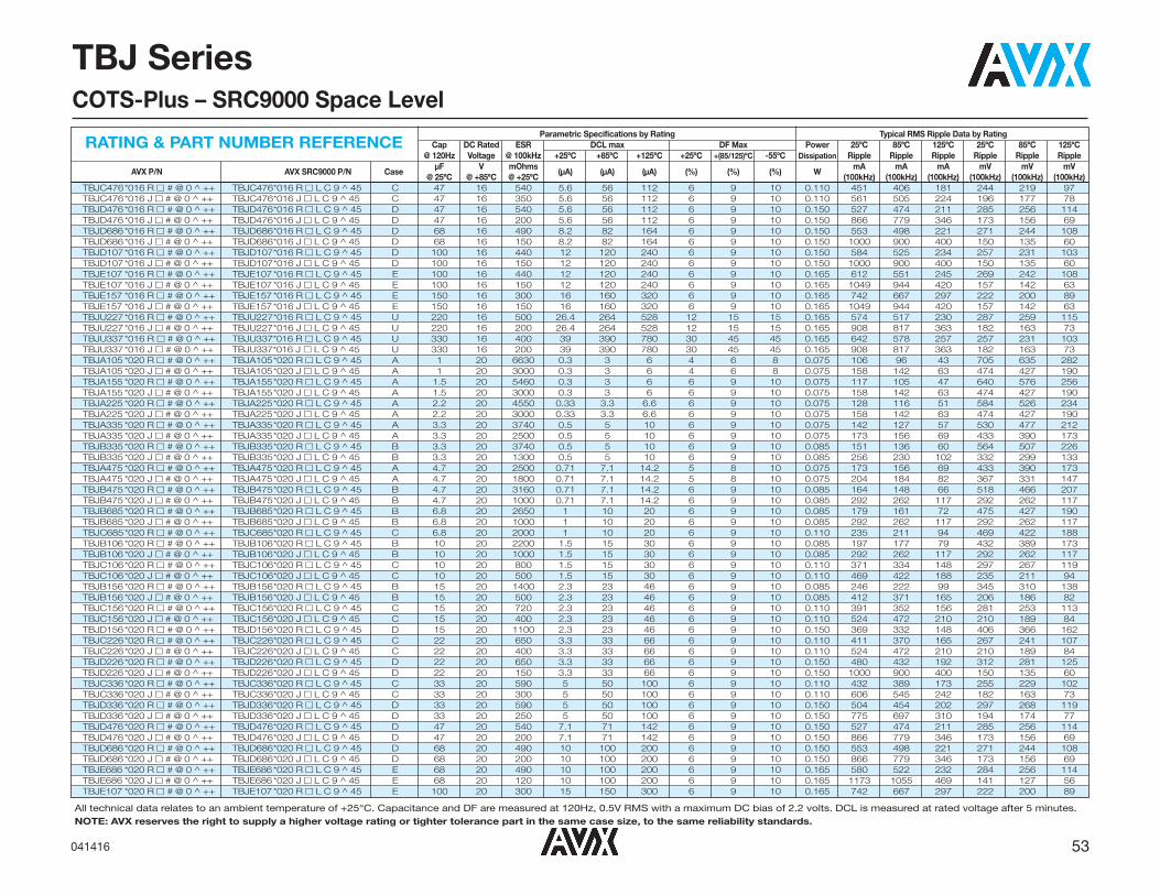
53041416
All technical data relates to an ambient temperature of +25°C. Capacitance and DF are measured at 120Hz, 0.5V RMS with a maximum DC bias of 2.2 volts. DCL is measured at rated voltage after 5 minutes.NOTE: AVX reserves the right to supply a higher voltage rating or tighter tolerance part in the same case size, to the same reliability standards.
TBJ SeriesCOTS-Plus – SRC9000 Space Level
Parametric Specifications by Rating Typical RMS Ripple Data by RatingCap DC Rated ESR DCL max DF Max Power 25ºC 85ºC 125ºC 25ºC 85ºC 125ºC
@ 120Hz Voltage @ 100kHz +25ºC +85ºC +125ºC +25ºC +(85/125)ºC -55ºC Dissipation Ripple Ripple Ripple Ripple Ripple Ripple
AVX P/N AVX SRC9000 P/N CaseμF V mOhms
(μA) (μA) (μA) (%) (%) (%) WmA mA mA mV mV mV
@ 25ºC @ +85ºC @ +25ºC (100kHz) (100kHz) (100kHz) (100kHz) (100kHz) (100kHz)TBJC476*016 R � # @ 0 ^ ++ TBJC476*016 R � L C 9 ^ 45 C 47 16 540 5.6 56 112 6 9 10 0.110 451 406 181 244 219 97TBJC476*016 J � # @ 0 ^ ++ TBJC476*016 J � L C 9 ^ 45 C 47 16 350 5.6 56 112 6 9 10 0.110 561 505 224 196 177 78TBJD476*016 R � # @ 0 ^ ++ TBJD476*016 R � L C 9 ^ 45 D 47 16 540 5.6 56 112 6 9 10 0.150 527 474 211 285 256 114TBJD476*016 J � # @ 0 ^ ++ TBJD476*016 J � L C 9 ^ 45 D 47 16 200 5.6 56 112 6 9 10 0.150 866 779 346 173 156 69TBJD686*016 R � # @ 0 ^ ++ TBJD686*016 R � L C 9 ^ 45 D 68 16 490 8.2 82 164 6 9 10 0.150 553 498 221 271 244 108TBJD686*016 J � # @ 0 ^ ++ TBJD686*016 J � L C 9 ^ 45 D 68 16 150 8.2 82 164 6 9 10 0.150 1000 900 400 150 135 60TBJD107*016 R � # @ 0 ^ ++ TBJD107*016 R � L C 9 ^ 45 D 100 16 440 12 120 240 6 9 10 0.150 584 525 234 257 231 103TBJD107*016 J � # @ 0 ^ ++ TBJD107*016 J � L C 9 ^ 45 D 100 16 150 12 120 240 6 9 10 0.150 1000 900 400 150 135 60TBJE107 *016 R � # @ 0 ^ ++ TBJE107*016 R � L C 9 ^ 45 E 100 16 440 12 120 240 6 9 10 0.165 612 551 245 269 242 108TBJE107 *016 J � # @ 0 ^ ++ TBJE107*016 J � L C 9 ^ 45 E 100 16 150 12 120 240 6 9 10 0.165 1049 944 420 157 142 63TBJE157 *016 R � # @ 0 ^ ++ TBJE157*016 R � L C 9 ^ 45 E 150 16 300 16 160 320 6 9 10 0.165 742 667 297 222 200 89TBJE157 *016 J � # @ 0 ^ ++ TBJE157*016 J � L C 9 ^ 45 E 150 16 150 16 160 320 6 9 10 0.165 1049 944 420 157 142 63TBJU227*016 R � # @ 0 ^ ++ TBJU227*016 R � L C 9 ^ 45 U 220 16 500 26.4 264 528 12 15 15 0.165 574 517 230 287 259 115TBJU227*016 J � # @ 0 ^ ++ TBJU227*016 J � L C 9 ^ 45 U 220 16 200 26.4 264 528 12 15 15 0.165 908 817 363 182 163 73TBJU337*016 R � # @ 0 ^ ++ TBJU337*016 R � L C 9 ^ 45 U 330 16 400 39 390 780 30 45 45 0.165 642 578 257 257 231 103TBJU337*016 J � # @ 0 ^ ++ TBJU337*016 J � L C 9 ^ 45 U 330 16 200 39 390 780 30 45 45 0.165 908 817 363 182 163 73TBJA105 *020 R � # @ 0 ^ ++ TBJA105*020 R � L C 9 ^ 45 A 1 20 6630 0.3 3 6 4 6 8 0.075 106 96 43 705 635 282TBJA105 *020 J � # @ 0 ^ ++ TBJA105*020 J � L C 9 ^ 45 A 1 20 3000 0.3 3 6 4 6 8 0.075 158 142 63 474 427 190TBJA155 *020 R � # @ 0 ^ ++ TBJA155*020 R � L C 9 ^ 45 A 1.5 20 5460 0.3 3 6 6 9 10 0.075 117 105 47 640 576 256TBJA155 *020 J � # @ 0 ^ ++ TBJA155*020 J � L C 9 ^ 45 A 1.5 20 3000 0.3 3 6 6 9 10 0.075 158 142 63 474 427 190TBJA225 *020 R � # @ 0 ^ ++ TBJA225*020 R � L C 9 ^ 45 A 2.2 20 4550 0.33 3.3 6.6 6 9 10 0.075 128 116 51 584 526 234TBJA225 *020 J � # @ 0 ^ ++ TBJA225*020 J � L C 9 ^ 45 A 2.2 20 3000 0.33 3.3 6.6 6 9 10 0.075 158 142 63 474 427 190TBJA335 *020 R � # @ 0 ^ ++ TBJA335*020 R � L C 9 ^ 45 A 3.3 20 3740 0.5 5 10 6 9 10 0.075 142 127 57 530 477 212TBJA335 *020 J � # @ 0 ^ ++ TBJA335*020 J � L C 9 ^ 45 A 3.3 20 2500 0.5 5 10 6 9 10 0.075 173 156 69 433 390 173TBJB335*020 R � # @ 0 ^ ++ TBJB335*020 R � L C 9 ^ 45 B 3.3 20 3740 0.5 5 10 6 9 10 0.085 151 136 60 564 507 226TBJB335*020 J � # @ 0 ^ ++ TBJB335*020 J � L C 9 ^ 45 B 3.3 20 1300 0.5 5 10 6 9 10 0.085 256 230 102 332 299 133TBJA475 *020 R � # @ 0 ^ ++ TBJA475*020 R � L C 9 ^ 45 A 4.7 20 2500 0.71 7.1 14.2 5 8 10 0.075 173 156 69 433 390 173TBJA475 *020 J � # @ 0 ^ ++ TBJA475*020 J � L C 9 ^ 45 A 4.7 20 1800 0.71 7.1 14.2 5 8 10 0.075 204 184 82 367 331 147TBJB475*020 R � # @ 0 ^ ++ TBJB475*020 R � L C 9 ^ 45 B 4.7 20 3160 0.71 7.1 14.2 6 9 10 0.085 164 148 66 518 466 207TBJB475*020 J � # @ 0 ^ ++ TBJB475*020 J � L C 9 ^ 45 B 4.7 20 1000 0.71 7.1 14.2 6 9 10 0.085 292 262 117 292 262 117TBJB685*020 R � # @ 0 ^ ++ TBJB685*020 R � L C 9 ^ 45 B 6.8 20 2650 1 10 20 6 9 10 0.085 179 161 72 475 427 190TBJB685*020 J � # @ 0 ^ ++ TBJB685*020 J � L C 9 ^ 45 B 6.8 20 1000 1 10 20 6 9 10 0.085 292 262 117 292 262 117TBJC685*020 R � # @ 0 ^ ++ TBJC685*020 R � L C 9 ^ 45 C 6.8 20 2000 1 10 20 6 9 10 0.110 235 211 94 469 422 188TBJB106*020 R � # @ 0 ^ ++ TBJB106*020 R � L C 9 ^ 45 B 10 20 2200 1.5 15 30 6 9 10 0.085 197 177 79 432 389 173TBJB106*020 J � # @ 0 ^ ++ TBJB106*020 J � L C 9 ^ 45 B 10 20 1000 1.5 15 30 6 9 10 0.085 292 262 117 292 262 117TBJC106*020 R � # @ 0 ^ ++ TBJC106*020 R � L C 9 ^ 45 C 10 20 800 1.5 15 30 6 9 10 0.110 371 334 148 297 267 119TBJC106*020 J � # @ 0 ^ ++ TBJC106*020 J � L C 9 ^ 45 C 10 20 500 1.5 15 30 6 9 10 0.110 469 422 188 235 211 94TBJB156*020 R � # @ 0 ^ ++ TBJB156*020 R � L C 9 ^ 45 B 15 20 1400 2.3 23 46 6 9 10 0.085 246 222 99 345 310 138TBJB156*020 J � # @ 0 ^ ++ TBJB156*020 J � L C 9 ^ 45 B 15 20 500 2.3 23 46 6 9 10 0.085 412 371 165 206 186 82TBJC156*020 R � # @ 0 ^ ++ TBJC156*020 R � L C 9 ^ 45 C 15 20 720 2.3 23 46 6 9 10 0.110 391 352 156 281 253 113TBJC156*020 J � # @ 0 ^ ++ TBJC156*020 J � L C 9 ^ 45 C 15 20 400 2.3 23 46 6 9 10 0.110 524 472 210 210 189 84TBJD156*020 R � # @ 0 ^ ++ TBJD156*020 R � L C 9 ^ 45 D 15 20 1100 2.3 23 46 6 9 10 0.150 369 332 148 406 366 162TBJC226*020 R � # @ 0 ^ ++ TBJC226*020 R � L C 9 ^ 45 C 22 20 650 3.3 33 66 6 9 10 0.110 411 370 165 267 241 107TBJC226*020 J � # @ 0 ^ ++ TBJC226*020 J � L C 9 ^ 45 C 22 20 400 3.3 33 66 6 9 10 0.110 524 472 210 210 189 84TBJD226*020 R � # @ 0 ^ ++ TBJD226*020 R � L C 9 ^ 45 D 22 20 650 3.3 33 66 6 9 10 0.150 480 432 192 312 281 125TBJD226*020 J � # @ 0 ^ ++ TBJD226*020 J � L C 9 ^ 45 D 22 20 150 3.3 33 66 6 9 10 0.150 1000 900 400 150 135 60TBJC336*020 R � # @ 0 ^ ++ TBJC336*020 R � L C 9 ^ 45 C 33 20 590 5 50 100 6 9 10 0.110 432 389 173 255 229 102TBJC336*020 J � # @ 0 ^ ++ TBJC336*020 J � L C 9 ^ 45 C 33 20 300 5 50 100 6 9 10 0.110 606 545 242 182 163 73TBJD336*020 R � # @ 0 ^ ++ TBJD336*020 R � L C 9 ^ 45 D 33 20 590 5 50 100 6 9 10 0.150 504 454 202 297 268 119TBJD336*020 J � # @ 0 ^ ++ TBJD336*020 J � L C 9 ^ 45 D 33 20 250 5 50 100 6 9 10 0.150 775 697 310 194 174 77TBJD476*020 R � # @ 0 ^ ++ TBJD476*020 R � L C 9 ^ 45 D 47 20 540 7.1 71 142 6 9 10 0.150 527 474 211 285 256 114TBJD476*020 J � # @ 0 ^ ++ TBJD476*020 J � L C 9 ^ 45 D 47 20 200 7.1 71 142 6 9 10 0.150 866 779 346 173 156 69TBJD686*020 R � # @ 0 ^ ++ TBJD686*020 R � L C 9 ^ 45 D 68 20 490 10 100 200 6 9 10 0.150 553 498 221 271 244 108TBJD686*020 J � # @ 0 ^ ++ TBJD686*020 J � L C 9 ^ 45 D 68 20 200 10 100 200 6 9 10 0.150 866 779 346 173 156 69TBJE686 *020 R � # @ 0 ^ ++ TBJE686*020 R � L C 9 ^ 45 E 68 20 490 10 100 200 6 9 10 0.165 580 522 232 284 256 114TBJE686 *020 J � # @ 0 ^ ++ TBJE686*020 J � L C 9 ^ 45 E 68 20 120 10 100 200 6 9 10 0.165 1173 1055 469 141 127 56TBJE107 *020 R � # @ 0 ^ ++ TBJE107*020 R � L C 9 ^ 45 E 100 20 300 15 150 300 6 9 10 0.165 742 667 297 222 200 89
RATING & PART NUMBER REFERENCE

54 041416
TBJ SeriesCOTS-Plus – SRC9000 Space Level
All technical data relates to an ambient temperature of +25°C. Capacitance and DF are measured at 120Hz, 0.5V RMS with a maximum DC bias of 2.2 volts. DCL is measured at rated voltage after 5 minutes.
NOTE: AVX reserves the right to supply a higher voltage rating or tighter tolerance part in the same case size, to the same reliability standards.
Parametric Specifications by Rating Typical RMS Ripple Data by RatingCap DC Rated ESR DCL max DF Max Power 25ºC 85ºC 125ºC 25ºC 85ºC 125ºC
@ 120Hz Voltage @ 100kHz +25ºC +85ºC +125ºC +25ºC +(85/125)ºC -55ºC Dissipation Ripple Ripple Ripple Ripple Ripple Ripple
AVX P/N AVX SRC9000 P/N CaseμF V mOhms
(μA) (μA) (μA) (%) (%) (%) WmA mA mA mV mV mV
@ 25ºC @ +85ºC @ +25ºC (100kHz) (100kHz) (100kHz) (100kHz) (100kHz) (100kHz)TBJE107 *020 J � # @ 0 ^ ++ TBJE107*020 J � L C 9 ^ 45 E 100 20 150 15 150 300 6 9 10 0.165 1049 944 420 157 142 63TBJU157*020 R � # @ 0 ^ ++ TBJU157*020 R � L C 9 ^ 45 U 150 20 500 22 220 440 30 45 45 0.165 574 517 230 287 259 115TBJU157*020 J � # @ 0 ^ ++ TBJU157*020 J � L C 9 ^ 45 U 150 20 250 22 220 440 30 45 45 0.165 812 731 325 203 183 81TBJA474 *025 R � # @ 0 ^ ++ TBJA474*025 R � L C 9 ^ 45 A 0.47 25 9530 0.3 3 6 4 6 8 0.075 89 80 35 845 761 338TBJA474 *025 J � # @ 0 ^ ++ TBJA474*025 J � L C 9 ^ 45 A 0.47 25 7000 0.3 3 6 4 6 8 0.075 104 93 41 725 652 290TBJA684 *025 R � # @ 0 ^ ++ TBJA684*025 R � L C 9 ^ 45 A 0.68 25 7980 0.3 3 6 4 6 8 0.075 97 87 39 774 696 309TBJA684 *025 J � # @ 0 ^ ++ TBJA684*025 J � L C 9 ^ 45 A 0.68 25 6000 0.3 3 6 4 6 8 0.075 112 101 45 671 604 268TBJA105 *025 R � # @ 0 ^ ++ TBJA105*025 R � L C 9 ^ 45 A 1 25 6630 0.3 3 6 4 6 8 0.075 106 96 43 705 635 282TBJA105 *025 J � # @ 0 ^ ++ TBJA105*025 J � L C 9 ^ 45 A 1 25 3000 0.3 3 6 4 6 8 0.075 158 142 63 474 427 190TBJA155 *025 R � # @ 0 ^ ++ TBJA155*025 R � L C 9 ^ 45 A 1.5 25 5460 0.3 3 6 6 9 10 0.075 117 105 47 640 576 256TBJA155 *025 J � # @ 0 ^ ++ TBJA155*025 J � L C 9 ^ 45 A 1.5 25 3000 0.3 3 6 6 9 10 0.075 158 142 63 474 427 190TBJB155*025 R � # @ 0 ^ ++ TBJB155*025 R � L C 9 ^ 45 B 1.5 25 5000 0.3 3 6 6 9 10 0.085 130 117 52 652 587 261TBJA225 *025 R � # @ 0 ^ ++ TBJA225*025 R � L C 9 ^ 45 A 2.2 25 2900 0.41 4.1 8.2 6 9 10 0.075 161 145 64 466 420 187TBJA225 *025 J � # @ 0 ^ ++ TBJA225*025 J � L C 9 ^ 45 A 2.2 25 1600 0.41 4.1 8.2 6 9 10 0.075 217 195 87 346 312 139TBJB225*025 R � # @ 0 ^ ++ TBJB225*025 R � L C 9 ^ 45 B 2.2 25 4550 0.41 4.1 8.2 6 9 10 0.085 137 123 55 622 560 249TBJB225*025 J � # @ 0 ^ ++ TBJB225*025 J � L C 9 ^ 45 B 2.2 25 1200 0.41 4.1 8.2 6 9 10 0.085 266 240 106 319 287 128TBJB335*025 R � # @ 0 ^ ++ TBJB335*025 R � L C 9 ^ 45 B 3.3 25 3740 0.62 6.2 12.4 6 9 10 0.085 151 136 60 564 507 226TBJB335*025 J � # @ 0 ^ ++ TBJB335*025 J � L C 9 ^ 45 B 3.3 25 2000 0.62 6.2 12.4 6 9 10 0.085 206 186 82 412 371 165TBJB475*025 R � # @ 0 ^ ++ TBJB475*025 R � L C 9 ^ 45 B 4.7 25 3160 0.88 8.8 17.6 6 9 10 0.085 164 148 66 518 466 207TBJB475*025 J � # @ 0 ^ ++ TBJB475*025 J � L C 9 ^ 45 B 4.7 25 1000 0.88 8.8 17.6 6 9 10 0.085 292 262 117 292 262 117TBJB685*025 R � # @ 0 ^ ++ TBJB685*025 R � L C 9 ^ 45 B 6.8 25 1500 1.3 13 26 6 9 10 0.085 238 214 95 357 321 143TBJB685*025 J � # @ 0 ^ ++ TBJB685*025 J � L C 9 ^ 45 B 6.8 25 1000 1.3 13 26 6 9 10 0.085 292 262 117 292 262 117TBJC685*025 R � # @ 0 ^ ++ TBJC685*025 R � L C 9 ^ 45 C 6.8 25 1070 1.3 13 26 6 9 10 0.110 321 289 128 343 309 137TBJC685*025 J � # @ 0 ^ ++ TBJC685*025 J � L C 9 ^ 45 C 6.8 25 600 1.3 13 26 6 9 10 0.110 428 385 171 257 231 103TBJC106*025 R � # @ 0 ^ ++ TBJC106*025 R � L C 9 ^ 45 C 10 25 800 1.9 19 38 6 9 10 0.110 371 334 148 297 267 119TBJC106*025 J � # @ 0 ^ ++ TBJC106*025 J � L C 9 ^ 45 C 10 25 600 1.9 19 38 6 9 10 0.110 428 385 171 257 231 103TBJD106*025 R � # @ 0 ^ ++ TBJD106*025 R � L C 9 ^ 45 D 10 25 1200 1.9 19 38 6 9 10 0.150 354 318 141 424 382 170TBJC156*025 R � # @ 0 ^ ++ TBJC156*025 R � L C 9 ^ 45 C 15 25 720 2.8 28 56 6 9 10 0.110 391 352 156 281 253 113TBJC156*025 J � # @ 0 ^ ++ TBJC156*025 J � L C 9 ^ 45 C 15 25 500 2.8 28 56 6 9 10 0.110 469 422 188 235 211 94TBJD156*025 R � # @ 0 ^ ++ TBJD156*025 R � L C 9 ^ 45 D 15 25 720 2.8 28 56 6 9 10 0.150 456 411 183 329 296 131TBJD156*025 J � # @ 0 ^ ++ TBJD156*025 J � L C 9 ^ 45 D 15 25 300 2.8 28 56 6 9 10 0.150 707 636 283 212 191 85TBJD226*025 R � # @ 0 ^ ++ TBJD226*025 R � L C 9 ^ 45 D 22 25 650 4.1 41 82 6 9 10 0.150 480 432 192 312 281 125TBJD226*025 J � # @ 0 ^ ++ TBJD226*025 J � L C 9 ^ 45 D 22 25 300 4.1 41 82 6 9 10 0.150 707 636 283 212 191 85TBJD336*025 R � # @ 0 ^ ++ TBJD336*025 R � L C 9 ^ 45 D 33 25 590 6.2 62 124 6 9 10 0.150 504 454 202 297 268 119TBJD336*025 J � # @ 0 ^ ++ TBJD336*025 J � L C 9 ^ 45 D 33 25 400 6.2 62 124 6 9 10 0.150 612 551 245 245 220 98TBJD476*025 R � # @ 0 ^ ++ TBJD476*025 R � L C 9 ^ 45 D 47 25 540 8.8 88 176 6 9 10 0.150 527 474 211 285 256 114TBJD476*025 J � # @ 0 ^ ++ TBJD476*025 J � L C 9 ^ 45 D 47 25 250 8.8 88 176 6 9 10 0.150 775 697 310 194 174 77TBJE476 *025 R � # @ 0 ^ ++ TBJE476*025 R � L C 9 ^ 45 E 47 25 540 8.8 88 176 6 9 10 0.165 553 497 221 298 269 119TBJE476 *025 J � # @ 0 ^ ++ TBJE476*025 J � L C 9 ^ 45 E 47 25 150 8.8 88 176 6 9 10 0.165 1049 944 420 157 142 63TBJU686*025 R � # @ 0 ^ ++ TBJU686*025 R � L C 9 ^ 45 U 68 25 500 12 120 240 30 45 45 0.165 574 517 230 287 259 115TBJU107*025 R � # @ 0 ^ ++ TBJU107*025 R � L C 9 ^ 45 U 100 25 500 18 180 360 30 45 45 0.165 574 517 230 287 259 115TBJA104 *035 R � # @ 0 ^ ++ TBJA104*035 R � L C 9 ^ 45 A 0.1 35 20000 0.3 3 6 4 6 8 0.075 61 55 24 1225 1102 490TBJA154 *035 R � # @ 0 ^ ++ TBJA154*035 R � L C 9 ^ 45 A 0.15 35 16470 0.3 3 6 4 6 8 0.075 67 61 27 1111 1000 445TBJA154 *035 J � # @ 0 ^ ++ TBJA154*035 J � L C 9 ^ 45 A 0.15 35 6000 0.3 3 6 4 6 8 0.075 112 101 45 671 604 268TBJA224 *035 R � # @ 0 ^ ++ TBJA224*035 R � L C 9 ^ 45 A 0.22 35 13710 0.3 3 6 4 6 8 0.075 74 67 30 1014 913 406TBJA224 *035 J � # @ 0 ^ ++ TBJA224*035 J � L C 9 ^ 45 A 0.22 35 6000 0.3 3 6 4 6 8 0.075 112 101 45 671 604 268TBJA334 *035 R � # @ 0 ^ ++ TBJA334*035 R � L C 9 ^ 45 A 0.33 35 11280 0.3 3 6 4 6 8 0.075 82 73 33 920 828 368TBJA334 *035 J � # @ 0 ^ ++ TBJA334*035 J � L C 9 ^ 45 A 0.33 35 6000 0.3 3 6 4 6 8 0.075 112 101 45 671 604 268TBJA474 *035 R � # @ 0 ^ ++ TBJA474*035 R � L C 9 ^ 45 A 0.47 35 9530 0.3 3 6 4 6 8 0.075 89 80 35 845 761 338TBJA474 *035 J � # @ 0 ^ ++ TBJA474*035 J � L C 9 ^ 45 A 0.47 35 4000 0.3 3 6 4 6 8 0.075 137 123 55 548 493 219TBJA684 *035 R � # @ 0 ^ ++ TBJA684*035 R � L C 9 ^ 45 A 0.68 35 7980 0.3 3 6 4 6 8 0.075 97 87 39 774 696 309TBJA684 *035 J � # @ 0 ^ ++ TBJA684*035 J � L C 9 ^ 45 A 0.68 35 6000 0.3 3 6 4 6 8 0.075 112 101 45 671 604 268TBJA105 *035 R � # @ 0 ^ ++ TBJA105*035 R � L C 9 ^ 45 A 1 35 6630 0.3 3 6 4 6 8 0.075 106 96 43 705 635 282TBJA105 *035 J � # @ 0 ^ ++ TBJA105*035 J � L C 9 ^ 45 A 1 35 3000 0.3 3 6 4 6 8 0.075 158 142 63 474 427 190TBJB105*035 R � # @ 0 ^ ++ TBJB105*035 R � L C 9 ^ 45 B 1 35 3400 0.3 3 6 4 6 8 0.085 158 142 63 538 484 215TBJB105*035 J � # @ 0 ^ ++ TBJB105*035 J � L C 9 ^ 45 B 1 35 2000 0.3 3 6 4 6 8 0.085 206 186 82 412 371 165TBJA155 *035 R � # @ 0 ^ ++ TBJA155*035 R � L C 9 ^ 45 A 1.5 35 3100 0.39 3.9 7.8 6 9 10 0.075 156 140 62 482 434 193
RATING & PART NUMBER REFERENCE

55041416
TBJ SeriesCOTS-Plus – SRC9000 Space Level
All technical data relates to an ambient temperature of +25°C. Capacitance and DF are measured at 120Hz, 0.5V RMS with a maximum DC bias of 2.2 volts. DCL is measured at rated voltage after 5 minutes.
NOTE: AVX reserves the right to supply a higher voltage rating or tighter tolerance part in the same case size, to the same reliability standards.
Parametric Specifications by Rating Typical RMS Ripple Data by RatingCap DC Rated ESR DCL max DF Max Power 25ºC 85ºC 125ºC 25ºC 85ºC 125ºC
@ 120Hz Voltage @ 100kHz +25ºC +85ºC +125ºC +25ºC +(85/125)ºC -55ºC Dissipation Ripple Ripple Ripple Ripple Ripple Ripple
AVX P/N AVX SRC9000 P/N CaseμF V mOhms
(μA) (μA) (μA) (%) (%) (%) WmA mA mA mV mV mV
@ 25ºC @ +85ºC @ +25ºC (100kHz) (100kHz) (100kHz) (100kHz) (100kHz) (100kHz)TBJA155 *035 J � # @ 0 ^ ++ TBJA155*035 J � L C 9 ^ 45 A 1.5 35 2000 0.39 3.9 7.8 6 9 10 0.075 194 174 77 387 349 155TBJB155*035 R � # @ 0 ^ ++ TBJB155*035 R � L C 9 ^ 45 B 1.5 35 5460 0.39 3.9 7.8 6 9 10 0.085 125 112 50 681 613 272TBJB155*035 J � # @ 0 ^ ++ TBJB155*035 J � L C 9 ^ 45 B 1.5 35 2500 0.39 3.9 7.8 6 9 10 0.085 184 166 74 461 415 184TBJB225*035 R � # @ 0 ^ ++ TBJB225*035 R � L C 9 ^ 45 B 2.2 35 4550 0.58 5.8 11.6 6 9 10 0.085 137 123 55 622 560 249TBJB225*035 J � # @ 0 ^ ++ TBJB225*035 J � L C 9 ^ 45 B 2.2 35 2000 0.58 5.8 11.6 6 9 10 0.085 206 186 82 412 371 165TBJB335*035 R � # @ 0 ^ ++ TBJB335*035 R � L C 9 ^ 45 B 3.3 35 3740 0.87 8.7 17.4 6 9 10 0.085 151 136 60 564 507 226TBJB335*035 J � # @ 0 ^ ++ TBJB335*035 J � L C 9 ^ 45 B 3.3 35 1000 0.87 8.7 17.4 6 9 10 0.085 292 262 117 292 262 117TBJC335*035 R � # @ 0 ^ ++ TBJC335*035 R � L C 9 ^ 45 C 3.3 35 1840 0.87 8.7 17.4 6 9 10 0.110 245 220 98 450 405 180TBJC335*035 J � # @ 0 ^ ++ TBJC335*035 J � L C 9 ^ 45 C 3.3 35 800 0.87 8.7 17.4 6 9 10 0.110 371 334 148 297 267 119TBJD335*035 R � # @ 0 ^ ++ TBJD335*035 R � L C 9 ^ 45 D 3.3 35 2000 0.87 8.7 17.4 6 9 10 0.150 274 246 110 548 493 219TBJB475*035 R � # @ 0 ^ ++ TBJB475*035 R � L C 9 ^ 45 B 4.7 35 2200 1.2 12 24 6 9 10 0.085 197 177 79 432 389 173TBJB475*035 J � # @ 0 ^ ++ TBJB475*035 J � L C 9 ^ 45 B 4.7 35 1500 1.2 12 24 6 9 10 0.085 238 214 95 357 321 143TBJC475*035 R � # @ 0 ^ ++ TBJC475*035 R � L C 9 ^ 45 C 4.7 35 1410 1.2 12 24 6 9 10 0.110 279 251 112 394 354 158TBJC475*035 J � # @ 0 ^ ++ TBJC475*035 J � L C 9 ^ 45 C 4.7 35 600 1.2 12 24 6 9 10 0.110 428 385 171 257 231 103TBJD475*035 R � # @ 0 ^ ++ TBJD475*035 R � L C 9 ^ 45 D 4.7 35 1500 1.2 12 24 6 9 10 0.150 316 285 126 474 427 190TBJC685*035 R � # @ 0 ^ ++ TBJC685*035 R � L C 9 ^ 45 C 6.8 35 1070 1.8 18 36 6 9 10 0.110 321 289 128 343 309 137TBJC685*035 J � # @ 0 ^ ++ TBJC685*035 J � L C 9 ^ 45 C 6.8 35 600 1.8 18 36 6 9 10 0.110 428 385 171 257 231 103TBJD685*035 R � # @ 0 ^ ++ TBJD685*035 R � L C 9 ^ 45 D 6.8 35 1300 1.8 18 36 6 9 10 0.150 340 306 136 442 397 177TBJC106*035 R � # @ 0 ^ ++ TBJC106*035 R � L C 9 ^ 45 C 10 35 800 2.6 26 52 6 9 10 0.110 371 334 148 297 267 119TBJC106*035 J � # @ 0 ^ ++ TBJC106*035 J � L C 9 ^ 45 C 10 35 600 2.6 26 52 6 9 10 0.110 428 385 171 257 231 103TBJD106*035 R � # @ 0 ^ ++ TBJD106*035 R � L C 9 ^ 45 D 10 35 800 2.6 26 52 6 9 10 0.150 433 390 173 346 312 139TBJD106*035 J � # @ 0 ^ ++ TBJD106*035 J � L C 9 ^ 45 D 10 35 250 2.6 26 52 6 9 10 0.150 775 697 310 194 174 77TBJD156*035 R � # @ 0 ^ ++ TBJD156*035 R � L C 9 ^ 45 D 15 35 720 3.9 39 78 6 9 10 0.150 456 411 183 329 296 131TBJD156*035 J � # @ 0 ^ ++ TBJD156*035 J � L C 9 ^ 45 D 15 35 225 3.9 39 78 6 9 10 0.150 816 735 327 184 165 73TBJD226*035 R � # @ 0 ^ ++ TBJD226*035 R � L C 9 ^ 45 D 22 35 650 5.8 58 116 6 9 10 0.150 480 432 192 312 281 125TBJD226*035 J � # @ 0 ^ ++ TBJD226*035 J � L C 9 ^ 45 D 22 35 200 5.8 58 116 6 9 10 0.150 866 779 346 173 156 69TBJE336 *035 R � # @ 0 ^ ++ TBJE336*035 R � L C 9 ^ 45 E 33 35 590 8.7 87 174 6 9 10 0.165 529 476 212 312 281 125TBJE336 *035 J � # @ 0 ^ ++ TBJE336*035 J � L C 9 ^ 45 E 33 35 250 8.7 87 174 6 9 10 0.165 812 731 325 203 183 81TBJU476*035 R � # @ 0 ^ ++ TBJU476*035 R � LC 9 ^ 45 U 47 35 400 12.3 123 246 10 12 12 0.165 642 578 257 257 231 103TBJU476*035 J � # @ 0 ^ ++ TBJU476*035 J � LC 9 ^ 45 U 47 35 200 12.3 123 246 10 12 12 0.165 908 817 363 182 163 73TBJA224 *050 R � # @ 0 ^ ++ TBJA224*050 R � L C 9 ^ 45 A 0.22 50 7500 0.3 3 6 4 6 8 0.075 100 90 40 750 675 300TBJA224 *050 J � # @ 0 ^ ++ TBJA224*050 J � L C 9 ^ 45 A 0.22 50 7000 0.3 3 6 4 6 8 0.075 104 93 41 725 652 290TBJA334 *050 R � # @ 0 ^ ++ TBJA334*050 R � L C 9 ^ 45 A 0.33 50 7000 0.3 3 6 4 6 8 0.075 104 93 41 725 652 290TBJB474*050 R � # @ 0 ^ ++ TBJB474*050 R � L C 9 ^ 45 B 0.47 50 5000 0.3 3 6 4 6 8 0.085 130 117 52 652 587 261TBJB684*050 R � # @ 0 ^ ++ TBJB684*050 R � L C 9 ^ 45 B 0.68 50 4000 0.3 3 6 4 6 8 0.085 146 131 58 583 525 233TBJB684*050 J � # @ 0 ^ ++ TBJB684*050 J � L C 9 ^ 45 B 0.68 50 2000 0.3 3 6 4 6 8 0.085 206 186 82 412 371 165TBJB105*050 R � # @ 0 ^ ++ TBJB105*050 R � L C 9 ^ 45 B 1 50 3400 0.4 4 8 4 6 8 0.085 158 142 63 538 484 215TBJB105*050 J � # @ 0 ^ ++ TBJB105*050 J � L C 9 ^ 45 B 1 50 2000 0.4 4 8 4 6 8 0.085 206 186 82 412 371 165TBJC105*050 R � # @ 0 ^ ++ TBJC105*050 R � L C 9 ^ 45 C 1 50 3000 0.4 4 8 4 6 8 0.110 191 172 77 574 517 230TBJC155*050 R � # @ 0 ^ ++ TBJC155*050 R � L C 9 ^ 45 C 1.5 50 2500 0.6 6 12 6 9 10 0.110 210 189 84 524 472 210TBJC155*050 J � # @ 0 ^ ++ TBJC155*050 J � L C 9 ^ 45 C 1.5 50 1500 0.6 6 12 6 9 10 0.110 271 244 108 406 366 162TBJC225*050 R � # @ 0 ^ ++ TBJC225*050 R � L C 9 ^ 45 C 2.2 50 1700 0.8 8 16 6 9 10 0.110 254 229 102 432 389 173TBJC225*050 J � # @ 0 ^ ++ TBJC225*050 J � L C 9 ^ 45 C 2.2 50 1000 0.8 8 16 6 9 10 0.110 332 298 133 332 298 133TBJD225*050 R � # @ 0 ^ ++ TBJD225*050 R � L C 9 ^ 45 D 2.2 50 2000 0.8 8 16 4.5 7 9 0.150 274 246 110 548 493 219TBJD225*050 J � # @ 0 ^ ++ TBJD225*050 J � L C 9 ^ 45 D 2.2 50 1200 0.8 8 16 4.5 7 9 0.150 354 318 141 424 382 170TBJC335*050 R � # @ 0 ^ ++ TBJC335*050 R � L C 9 ^ 45 C 3.3 50 1400 1.2 12 24 6 9 10 0.110 280 252 112 392 353 157TBJC335*050 J � # @ 0 ^ ++ TBJC335*050 J � L C 9 ^ 45 C 3.3 50 1000 1.2 12 24 6 9 10 0.110 332 298 133 332 298 133TBJD335*050 R � # @ 0 ^ ++ TBJD335*050 R � L C 9 ^ 45 D 3.3 50 1100 1.2 12 24 4.5 7 9 0.150 369 332 148 406 366 162TBJD335*050 J � # @ 0 ^ ++ TBJD335*050 J � L C 9 ^ 45 D 3.3 50 800 1.2 12 24 4.5 7 9 0.150 433 390 173 346 312 139TBJD475*050 R � # @ 0 ^ ++ TBJD475*050 R � L C 9 ^ 45 D 4.7 50 900 1.8 18 36 4.5 7 9 0.150 408 367 163 367 331 147TBJD475*050 J � # @ 0 ^ ++ TBJD475*050 J � L C 9 ^ 45 D 4.7 50 600 1.8 18 36 4.5 7 9 0.150 500 450 200 300 270 120TBJD685*050 R � # @ 0 ^ ++ TBJD685*050 R � L C 9 ^ 45 D 6.8 50 700 2.6 26 52 4.5 7 9 0.150 463 417 185 324 292 130TBJE106 *050 R � # @ 0 ^ ++ TBJE106*050 R � L C 9 ^ 45 E 10 50 700 3.8 38 76 4.5 7 9 0.165 486 437 194 340 306 136TBJE106 *050 J � # @ 0 ^ ++ TBJE106*050 J � L C 9 ^ 45 E 10 50 300 3.8 38 76 4.5 7 9 0.165 742 667 297 222 200 89TBJU156*050 R � # @ 0 ^ ++ TBJU156*050 R � L C 9 ^ 45 U 15 50 500 5.6 56 112 30 45 45 0.165 574 517 230 287 259 115TBJU226*050R � # @ 0 ^ ++ TBJU226*050 R � L C 9 ^ 45 U 22 50 500 8.2 82 164 30 45 45 0.165 574 517 230 287 259 115
RATING & PART NUMBER REFERENCE

56 041416
NOTE: EIA standards for Low ESR solid tantalum capacitors allowan ESR movement of 1.25 times initial limit post mounting.
DSCC Dwgs 07016 & 95158COTS-Plus
The DSCC 07016 & 95158 famalies,based on the CWR11 form factor, are highreliability series encompassing the currentrange of EIA Low ESR ratings. DSCC07016 has the widest range of case sizes,capacitance / voltage ratings, and is offeredwith Weibull Grade “B” and “C” reliabilitywith all MIL-PRF-55365 Rev. G surge testoptions (“A”, “B” & “C”). For Space Level applications, AVXSRC9000 qualification is recommend.Please refer to the TBJ COTS-PlusSRC9000 datasheet for part number avail-ability.
There are four termination finishes available:solder plated, fused solder plated, hot sol-der dipped and gold plated (these corre-spond to “H”, “K”, “C” and “B” termination,respectively, per MIL-PRF-55365). The molding compound has been selectedto meet the requirements of UL94V-0(Flame Retardancy) and outgassing re-quirements of ASTM E-595.For moisture sensitivity levels please refer tothe High Reliability Tantalum MSL section lo-cated in the back of the High Reliability Tan-talum Catalog.
Polarity Stripe (+)Capacitance CodeRated VoltageManufacturer’s IDLot Number
L
SA A W1
W
H
Capacitance Rated Voltage DC (VR) to 85ºC μF Code 4V (G) 6V (J) 10V (A) 16V (C) 20V (D) 25V (E) 35V (V) 50V (T) 0.15 154 A(15000) 0.22 224 A(18000) 0.47 474 A(12000) A(9500)/B(9500) 0.68 684 A(10000) A(8000) A(7900) 1.0 105 A(8000) A(7500) A(6600)/B(7000) 1.5 155 A(6500) A(3000,7500) A(7500)/B(5200) C(2000)/D(1500) 2.2 225 A(5500) A(3000) A(7000)/B(2000) B(2000) D(1200) 3.3 335 A(8000) A(3500,5000) B(2000) B(1000) D(800) 4.7 475 A(6000) A(5000) A(2000) A(1800,4000) A(3100) B(1500)
D(300) B(1000) B(700,1500) C(600)/D(450) 6.8 685 A(5000) A(4000) A(1500/B(1200) B(1000) B(700,2800) C(350)/D(400)
D(300,600) C(700) E(300) 10 106 A(4000) A(1800,3000) A(3000)/B(900) B(500,1000) C(300,500) C(1600)/D(125,300) C(700) E(250) 15 156 A(3500) A(1000,3200) B(500,800) B(500)/C(450) D(275)/E(200) C(450)/D(100,300) B(600) D(275) E(225) 22 226 A(3000)/B(600) B(500,700) B(500,600) B(600)/C(400) C(275,400) D(125,400) C(300) C(150,375) D(275) D(100,200)/E(225) E(125,300) 33 336 A(3000) B(600) A(700)/B(425,650) C(100,300) C(300) D(90,300) D(200,300) C (500) D(250) D(100, 200) E(100,175) E(300) 47 476 C(300) C(200,350) C(110,350) D(100,200) D(175,250) E(250)/V(200) D(200) D(80,200) E(150) 68 686 A(1500) B(500)/C(200) C(80,300) D(150) D(70,200) V(95) D(175) D(150)/E(150) E(150,200) 100 107 A(1400) C(75,150) C(75,200) D(50,125) V(60) B(900) D(50,100)/E(100) E(125) 150 157 D(125)/E(125) D(50,100)/E(100) D(60,150)/V(45) 220 227 D(100,125) D(50,150) V(50) E(100) E(50,100) 330 337 E(50,150) D(50,150) E(50,100)/V(40) 470 477 E(50,200)/V(40) E(50,200)/V(40) 1000 108 E(200)
CAPACITANCE AND RATED VOLTAGE, VR (EIA VOLTAGE CODE) RANGE LETTER DENOTES CASE SIZE (ESR LIMITS IN PARENTHESES)
CASE DIMENSIONS: millimeters (inches)
Code
EIA EIA L±0.20 W+0.20 (0.008) H+0.20 (0.008) W1±0.20 A+0.30 (0.012) S Min. Code Metric (0.008) -0.10 (0.004) -0.10 (0.004) (0.008) -0.20 (0.008)
A 1206 3216-18 3.20 (0.126) 1.60 (0.063) 1.60 (0.063) 1.20 (0.047) 0.80 (0.031) 1.10 (0.043)
B 1210 3528-21 3.50 (0.138) 2.80 (0.110) 1.90 (0.075) 2.20 (0.087) 0.80 (0.031) 1.40 (0.055)
C 2312 6032-28 6.00 (0.236) 3.20 (0.126) 2.60 (0.102) 2.20 (0.087) 1.30 (0.051) 2.90 (0.114)
D 2917 7343-31 7.30 (0.287) 4.30 (0.169) 2.90 (0.114) 2.40 (0.094) 1.30 (0.051) 4.40 (0.173)
E 2917 7343-43 7.30 (0.287) 4.30 (0.169) 4.10 (0.162) 2.40 (0.094) 1.30 (0.051) 4.40 (0.173)
V 2924 7361-38 7.30 (0.287) 6.10 (0.240) 3.55 (0.140) 3.10 (0.120) 1.30 (0.051) 4.40 (0.173)
W1 dimension applies to the termination width for A dimensional area only.
MARKING(Brown marking on gold body)
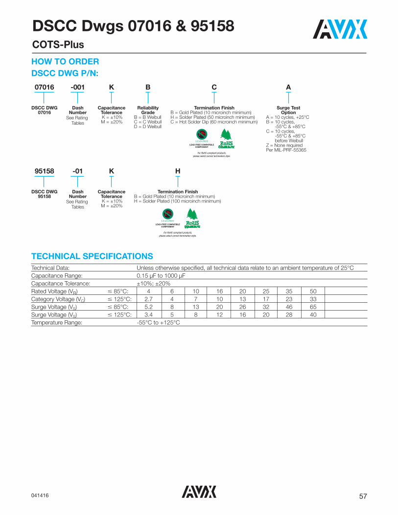
57041416
DSCC Dwgs 07016 & 95158COTS-Plus
Technical Data: Unless otherwise specified, all technical data relate to an ambient temperature of 25°CCapacitance Range: 0.15 μF to 1000 μFCapacitance Tolerance: ±10%; ±20%Rated Voltage (VR) � 85°C: 4 6 10 16 20 25 35 50Category Voltage (VC) � 125°C: 2.7 4 7 10 13 17 23 33Surge Voltage (VS) � 85°C: 5.2 8 13 20 26 32 46 65Surge Voltage (VS) � 125°C: 3.4 5 8 12 16 20 28 40Temperature Range: -55°C to +125°C
TECHNICAL SPECIFICATIONS
DSCC DWG P/N:HOW TO ORDER
K
CapacitanceTolerance
K = ±10% M = ±20%
A
Surge TestOption
A = 10 cycles, +25°CB = 10 cycles,
-55°C & +85°CC = 10 cycles,
-55°C & +85°C before Weibull
Z = None requiredPer MIL-PRF-55365
07016
DSCC DWG07016
-001
DashNumber
See RatingTables
B
ReliabilityGrade
B = B WeibullC = C WeibullD = D Weibull
K
CapacitanceTolerance
K = ±10% M = ±20%
95158
DSCC DWG95158
-01
DashNumber
See RatingTables
H
Termination FinishB = Gold Plated (10 microinch minimum)H = Solder Plated (100 microinch minimum)
C
Termination FinishB = Gold Plated (10 microinch minimum)H = Solder Plated (50 microinch minimum)C = Hot Solder Dip (60 microinch minimum)
LEAD-FREE COMPATIBLECOMPONENT
For RoHS compliant products, please select correct termination style.
LEAD-FREE COMPATIBLECOMPONENT
For RoHS compliant products, please select correct termination style.

58 041416
DSCC Dwgs 07016 & 95158COTS-Plus
Parametric Specifications by Rating per DSCC 95158 or 07016 where applicable Typical RMS Ripple Data by RatingCap DC Rated ESR DCL max DF Max Power 25ºC 85ºC 125ºC 25ºC 85ºC 125ºC
@ 120Hz Voltage @ 100kHz +25ºC +85ºC +125ºC +25ºC +(85/125)ºC -55ºC Dissipation Ripple Ripple Ripple Ripple Ripple Ripple
DSCC P/N CaseμF V mOhms
(μA) (μA) (μA) (%) (%) (%) WA A A V V V
@ 25ºC @ +85ºC @ +25ºC (100kHz) (100kHz) (100kHz) (100kHz) (100kHz) (100kHz)07016 001 * @ ^ + A 33 4 3000 1.4 14 17 6 9 9 0.075 0.16 0.14 0.06 0.47 0.43 0.1907016 002 * @ ^ + A 68 4 1500 2.7 27 32 10 12 14 0.075 0.22 0.20 0.09 0.34 0.30 0.1307016 003 * @ ^ + A 100 4 1400 4 40 48 30 36 42 0.075 0.23 0.21 0.09 0.32 0.29 0.1307016 004 * @ ^ + B 100 4 900 4 40 48 8 10 12 0.085 0.31 0.28 0.12 0.28 0.25 0.1107016 005 * @ ^ + E 1,000 4 200 40 400 480 60 90 90 0.165 0.91 0.82 0.36 0.18 0.16 0.0707016 006 * @ ^ + A 3.3 6 8000 0.5 5 6 6 9 9 0.075 0.10 0.09 0.04 0.77 0.70 0.3107016 007 * @ ^ + A 4.7 6 6000 0.5 5 6 6 9 10 0.075 0.11 0.10 0.04 0.67 0.60 0.2707016 008 * @ ^ + A 6.8 6 5000 0.5 5 6 6 9 10 0.075 0.12 0.11 0.05 0.61 0.55 0.2407016 009 * @ ^ + A 10 6 4000 0.6 10 11 6 9 10 0.075 0.14 0.12 0.05 0.55 0.49 0.2207016 010 * @ ^ + A 15 6 3500 0.9 10 11 6 9 10 0.075 0.15 0.13 0.06 0.51 0.46 0.2007016 011 * @ ^ + A 22 6 3000 1.4 14 17 6 9 10 0.075 0.16 0.14 0.06 0.47 0.43 0.1907016 012 * @ ^ + B 22 6 600 1.4 14 17 6 9 10 0.085 0.38 0.34 0.15 0.23 0.20 0.0907016 013 * @ ^ + B 33 6 600 2.1 21 25 6 9 10 0.085 0.38 0.34 0.15 0.23 0.20 0.0907016 014 * @ ^ + C 47 6 300 3 30 36 6 9 10 0.110 0.61 0.54 0.24 0.18 0.16 0.0707016 015 * @ ^ + B 68 6 500 4.3 43 51 8 10 12 0.085 0.41 0.37 0.16 0.21 0.19 0.0807016 016 * @ ^ + C 68 6 200 4.3 43 51 6 9 10 0.110 0.74 0.67 0.30 0.15 0.13 0.0695158 01 * ^ D 68 6 175 3.3 19.8 33 4 6 6 0.150 0.93 0.83 0.37 0.16 0.15 0.0607016 017 * @ ^ + C 100 6 150 6.3 63 76 6 9 10 0.110 0.86 0.77 0.34 0.13 0.12 0.0507016 018 * @ ^ + C 100 6 75 6.3 63 76 6 9 10 0.110 1.21 1.09 0.48 0.09 0.08 0.0407016 019 * @ ^ + D 150 6 125 9.5 95 113 6 9 10 0.150 1.10 0.99 0.44 0.14 0.12 0.0595158 02 * ^ E 150 6 125 7.2 43.2 72 6 8 8 0.165 1.15 1.03 0.46 0.14 0.13 0.0607016 020 * @ ^ + D 220 6 125 13.9 139 166 8 10 12 0.150 1.10 0.99 0.44 0.14 0.12 0.0595158 25 * ^ D 220 6 100 13.2 132 165 8 10 12 0.150 1.22 1.10 0.49 0.12 0.11 0.0595158 03 * ^ E 220 6 100 13.2 132 165 8 12 12 0.165 1.28 1.16 0.51 0.13 0.12 0.0507016 021 * @ ^ + E 330 6 150 20.8 208 249 8 10 12 0.165 1.05 0.94 0.42 0.16 0.14 0.0607016 022 * @ ^ + E 330 6 50 20.8 208 249 8 10 12 0.165 1.82 1.63 0.73 0.09 0.08 0.0407016 023 M @ ^ + E 470 6 200 29.6 296 355 10 12 14 0.165 0.91 0.82 0.36 0.18 0.16 0.0707016 024 M @ ^ + E 470 6 50 29.6 296 355 10 12 14 0.165 1.82 1.63 0.73 0.09 0.08 0.0407016 025 * @ ^ + V 470 6 40 29.6 296 355 10 12 12 0.250 2.50 2.25 1.00 0.10 0.09 0.0407016 026 * @ ^ + A 4.7 10 5000 0.5 5 6 6 9 10 0.075 0.12 0.11 0.05 0.61 0.55 0.2407016 027 * @ ^ + A 6.8 10 4000 0.7 7 8 6 9 10 0.075 0.14 0.12 0.05 0.55 0.49 0.2207016 028 * @ ^ + A 10 10 3000 1 10 12 6 9 10 0.075 0.16 0.14 0.06 0.47 0.43 0.1907016 029 * @ ^ + A 10 10 1800 1 10 12 6 9 10 0.075 0.20 0.18 0.08 0.37 0.33 0.1507016 030 * @ ^ + A 15 10 3200 1.6 16 19 6 9 10 0.075 0.15 0.14 0.06 0.49 0.44 0.2007016 031 * @ ^ + A 15 10 1000 1.6 16 19 6 9 10 0.075 0.27 0.25 0.11 0.27 0.25 0.1107016 032 * @ ^ + B 15 10 600 1.6 16 19 6 9 10 0.085 0.38 0.34 0.15 0.23 0.20 0.0907016 033 * @ ^ + B 22 10 700 2.2 22 26 6 9 10 0.085 0.35 0.31 0.14 0.24 0.22 0.1007016 034 * @ ^ + B 22 10 500 2.2 22 26 6 9 10 0.085 0.41 0.37 0.16 0.21 0.19 0.0807016 035 * @ ^ + C 22 10 300 2.2 22 26 6 9 10 0.110 0.61 0.54 0.24 0.18 0.16 0.0707016 036 * @ ^ + A 33 10 700 3.3 33 40 8 10 12 0.075 0.33 0.29 0.13 0.23 0.21 0.0907016 037 * @ ^ + B 33 10 650 3.3 33 40 6 9 10 0.085 0.36 0.33 0.14 0.24 0.21 0.0907016 038 * @ ^ + B 33 10 425 3.3 33 40 6 9 10 0.085 0.45 0.40 0.18 0.19 0.17 0.0807016 039 * @ ^ + C 33 10 500 3.3 33 40 6 9 10 0.110 0.47 0.42 0.19 0.23 0.21 0.0907016 040 * @ ^ + C 47 10 350 4.7 47 56 6 9 10 0.110 0.56 0.50 0.22 0.20 0.18 0.0807016 041 * @ ^ + C 47 10 200 4.7 47 56 6 9 10 0.110 0.74 0.67 0.30 0.15 0.13 0.0695158 -04 * ^ D 47 10 200 3.8 22.8 38 4 6 6 0.150 0.87 0.78 0.35 0.17 0.16 0.0707016 042 * @ ^ + C 68 10 300 6.8 68 82 8 10 12 0.110 0.61 0.54 0.24 0.18 0.16 0.0707016 043 * @ ^ + C 68 10 80 6.8 68 82 8 10 12 0.110 1.17 1.06 0.47 0.09 0.08 0.0407016 044 * @ ^ + D 68 10 150 6.8 68 82 6 9 10 0.150 1.00 0.90 0.40 0.15 0.14 0.0695158 05 * ^ E 68 10 150 5.4 32.4 54 4 6 6 0.165 1.05 0.94 0.42 0.16 0.14 0.0607016 045 * @ ^ + C 100 10 200 10 100 120 8 10 12 0.110 0.74 0.67 0.30 0.15 0.13 0.0607016 046 * @ ^ + C 100 10 75 10 100 120 8 10 12 0.110 1.21 1.09 0.48 0.09 0.08 0.0495158 06 * ^ D 100 10 100 10 100 125 8 12 12 0.150 1.22 1.10 0.49 0.12 0.11 0.0507016 047 * @ ^ + D 100 10 50 10 100 120 6 9 10 0.150 1.73 1.56 0.69 0.09 0.08 0.0395158 07 * ^ E 100 10 100 8 48 80 6 8 8 0.165 1.28 1.16 0.51 0.13 0.12 0.05
RATING & PART NUMBER REFERENCE
All technical data relates to an ambient temperature of +25°C. Capacitance and DF are measured at 120Hz, 0.5V RMS with a maximum DC bias of 2.2 volts. DCL is measured at rated voltage after 5 minutes.
NOTE: AVX reserves the right to supply a higher voltage rating or tighter tolerance part in the same case size, to the same reliability standards.

59041416
Parametric Specifications by Rating per DSCC 95158 or 07016 where applicable Typical RMS Ripple Data by RatingCap DC Rated ESR DCL max DF Max Power 25ºC 85ºC 125ºC 25ºC 85ºC 125ºC
@ 120Hz Voltage @ 100kHz +25ºC +85ºC +125ºC +25ºC +(85/125)ºC -55ºC Dissipation Ripple Ripple Ripple Ripple Ripple Ripple
DSCC P/N CaseμF V mOhms
(μA) (μA) (μA) (%) (%) (%) WA A A V V V
@ 25ºC @ +85ºC @ +25ºC (100kHz) (100kHz) (100kHz) (100kHz) (100kHz) (100kHz)95158 26 * ^ D 150 10 100 15 150 187.5 8 10 12 0.150 1.22 1.10 0.49 0.12 0.11 0.0507016 048 * @ ^ + D 150 10 50 15 150 180 8 10 12 0.150 1.73 1.56 0.69 0.09 0.08 0.0395158 08 * ^ E 150 10 100 15 150 187.5 8 12 12 0.165 1.28 1.16 0.51 0.13 0.12 0.0507016 049 * @ ^ + D 220 10 150 22 220 264 8 10 12 0.150 1.00 0.90 0.40 0.15 0.14 0.0607016 050 M @ ^ + D 220 10 50 15 150 180 8 10 12 0.150 1.73 1.56 0.69 0.09 0.08 0.0395158 28 * ^ E 220 10 100 15 150 187.5 8 10 12 0.165 1.28 1.16 0.51 0.13 0.12 0.0507016 051 * @ ^ + E 220 10 50 22 220 264 8 10 12 0.165 1.82 1.63 0.73 0.09 0.08 0.0407016 052 M @ ^ + D 330 10 150 33 330 396 8 10 12 0.150 1.00 0.90 0.40 0.15 0.14 0.0607016 053 M @ ^ + D 330 10 50 33 330 396 8 10 12 0.150 1.73 1.56 0.69 0.09 0.08 0.0307016 054 * @ ^ + E 330 10 100 33 330 396 8 10 12 0.165 1.28 1.16 0.51 0.13 0.12 0.0507016 055 * @ ^ + E 330 10 50 33 330 396 8 10 12 0.165 1.82 1.63 0.73 0.09 0.08 0.0407016 056 * @ ^ + V 330 10 40 33 330 396 8 10 12 0.250 2.50 2.25 1.00 0.10 0.09 0.0407016 057 M @ ^ + E 470 10 200 47 470 564 10 12 14 0.165 0.91 0.82 0.36 0.18 0.16 0.0707016 058 M @ ^ + E 470 10 50 47 470 564 10 12 14 0.165 1.82 1.63 0.73 0.09 0.08 0.0407016 059 * @ ^ + V 470 10 40 47 470 564 10 12 14 0.250 2.50 2.25 1.00 0.10 0.09 0.0407016 060 * @ ^ + A 2.2 16 5500 0.5 5 6 6 9 10 0.075 0.12 0.11 0.05 0.64 0.58 0.2607016 061 * @ ^ + A 3.3 16 5000 0.5 5 6 6 9 10 0.075 0.12 0.11 0.05 0.61 0.55 0.2407016 062 * @ ^ + A 3.3 16 3500 0.5 5 6 6 9 10 0.075 0.15 0.13 0.06 0.51 0.46 0.2007016 063 * @ ^ + A 4.7 16 2000 0.8 8 10 6 9 10 0.075 0.19 0.17 0.08 0.39 0.35 0.1507016 064 * @ ^ + A 6.8 16 1500 1.1 11 13 6 9 10 0.075 0.22 0.20 0.09 0.34 0.30 0.1307016 065 * @ ^ + B 6.8 16 1200 1.1 11 13 6 9 10 0.085 0.27 0.24 0.11 0.32 0.29 0.1307016 066 * @ ^ + A 10 16 3000 1.6 16 19 6 9 10 0.075 0.16 0.14 0.06 0.47 0.43 0.1907016 067 * @ ^ + B 10 16 900 1.6 16 19 6 9 10 0.085 0.32 0.29 0.13 0.26 0.23 0.1007016 068 * @ ^ + B 15 16 800 2.4 24 29 6 9 10 0.085 0.33 0.29 0.13 0.26 0.23 0.1007016 069 * @ ^ + B 15 16 500 2.4 24 29 6 9 10 0.085 0.41 0.37 0.16 0.21 0.19 0.0807016 070 * @ ^ + B 22 16 600 3.6 36 43 6 9 10 0.085 0.38 0.34 0.15 0.23 0.20 0.0907016 071 * @ ^ + C 22 16 375 3.6 36 43 6 9 10 0.110 0.54 0.49 0.22 0.20 0.18 0.0807016 072 * @ ^ + C 22 16 150 3.6 36 43 6 9 10 0.110 0.86 0.77 0.34 0.13 0.12 0.0507016 073 * @ ^ + B 22 16 500 3.6 36 43 6 9 10 0.085 0.41 0.37 0.16 0.21 0.19 0.0807016 074 * @ ^ + C 33 16 300 5.3 53 64 6 9 10 0.110 0.61 0.54 0.24 0.18 0.16 0.0707016 075 * @ ^ + C 33 16 100 5.3 53 64 6 9 10 0.110 1.05 0.94 0.42 0.10 0.09 0.0495158 09 * ^ D 33 16 250 4.2 25.2 42 4 6 6 0.150 0.77 0.70 0.31 0.19 0.17 0.0807016 076 * @ ^ + C 47 16 350 7.6 76 91 6 9 10 0.110 0.56 0.50 0.22 0.20 0.18 0.0807016 077 * @ ^ + C 47 16 110 7.6 76 91 6 9 10 0.110 1.00 0.90 0.40 0.11 0.10 0.0407016 078 * @ ^ + D 47 16 80 7.6 76 91 6 9 10 0.150 1.37 1.23 0.55 0.11 0.10 0.0495158 10 * ^ D 47 16 200 7.5 75 94 6 9 9 0.150 0.87 0.78 0.35 0.17 0.16 0.0707016 079 * @ ^ + D 68 16 150 10.9 109 131 6 9 10 0.150 1.00 0.90 0.40 0.15 0.14 0.0607016 080 * @ ^ + D 100 16 125 16 160 192 6 9 10 0.150 1.10 0.99 0.44 0.14 0.12 0.0507016 081 * @ ^ + D 100 16 50 16 160 192 6 9 10 0.150 1.73 1.56 0.69 0.09 0.08 0.0395158 11 * ^ E 100 16 125 16 160 200 8 12 12 0.165 1.15 1.03 0.46 0.14 0.13 0.0607016 082 M @ ^ + D 150 16 150 24 240 288 6 9 10 0.150 1.00 0.90 0.40 0.15 0.14 0.0607016 083 M @ ^ + D 150 16 60 24 240 288 6 9 10 0.150 1.58 1.42 0.63 0.09 0.09 0.0407016 084 * @ ^ + V 150 16 45 24 480 288 6 8 10 0.250 2.36 2.12 0.94 0.11 0.10 0.0407016 085 * @ ^ + V 220 16 50 35.2 352 422 8 10 12 0.250 2.24 2.01 0.89 0.11 0.10 0.0407016 086 * @ ^ + A 1.5 20 6500 0.5 5 6 6 8 10 0.075 0.11 0.10 0.04 0.70 0.63 0.2807016 087 * @ ^ + A 2.2 20 3000 0.5 5 6 6 8 10 0.075 0.16 0.14 0.06 0.47 0.43 0.1907016 088 * @ ^ + A 4.7 20 4000 1 10 12 6 8 10 0.075 0.14 0.12 0.05 0.55 0.49 0.2207016 089 * @ ^ + A 4.7 20 1800 1 10 12 6 8 10 0.075 0.20 0.18 0.08 0.37 0.33 0.1507016 090 * @ ^ + B 4.7 20 1000 2 20 24 6 8 10 0.085 0.29 0.26 0.12 0.29 0.26 0.1207016 091 * @ ^ + B 6.8 20 1000 1.4 14 17 6 8 10 0.085 0.29 0.26 0.12 0.29 0.26 0.1207016 092 * @ ^ + B 10 20 1000 0.7 7 8 6 8 10 0.085 0.29 0.26 0.12 0.29 0.26 0.1207016 093 * @ ^ + B 10 20 500 0.7 7 8 6 8 10 0.085 0.41 0.37 0.16 0.21 0.19 0.0807016 094 * @ ^ + C 10 20 700 1.4 14 17 6 8 10 0.110 0.40 0.36 0.16 0.28 0.25 0.1107016 095 * @ ^ + B 15 20 500 3 30 36 6 8 10 0.085 0.41 0.37 0.16 0.21 0.19 0.0807016 096 * @ ^ + C 15 20 450 3 30 36 6 8 10 0.110 0.49 0.44 0.20 0.22 0.20 0.0995158 12 * ^ D 15 20 275 2.4 14.4 24 4 6 6 0.150 0.74 0.66 0.30 0.20 0.18 0.08
RATING & PART NUMBER REFERENCE
DSCC Dwgs 07016 & 95158COTS-Plus
All technical data relates to an ambient temperature of +25°C. Capacitance and DF are measured at 120Hz, 0.5V RMS with a maximum DC bias of 2.2 volts. DCL is measured at rated voltage after 5 minutes.
NOTE: AVX reserves the right to supply a higher voltage rating or tighter tolerance part in the same case size, to the same reliability standards.

60 041416
Parametric Specifications by Rating per DSCC 95158 or 07016 where applicable Typical RMS Ripple Data by RatingCap DC Rated ESR DCL max DF Max Power 25ºC 85ºC 125ºC 25ºC 85ºC 125ºC
@ 120Hz Voltage @ 100kHz +25ºC +85ºC +125ºC +25ºC +(85/125)ºC -55ºC Dissipation Ripple Ripple Ripple Ripple Ripple Ripple
DSCC P/N CaseμF V mOhms
(μA) (μA) (μA) (%) (%) (%) WA A A V V V
@ 25ºC @ +85ºC @ +25ºC (100kHz) (100kHz) (100kHz) (100kHz) (100kHz) (100kHz)07016 097 * @ ^ + B 22 20 600 4.4 44 53 6 8 10 0.085 0.38 0.34 0.15 0.23 0.20 0.0907016 098 * @ ^ + C 22 20 400 4.4 44 53 6 8 10 0.110 0.52 0.47 0.21 0.21 0.19 0.0895158 13 * ^ D 22 20 275 3.5 21 35 4 6 6 0.150 0.74 0.66 0.30 0.20 0.18 0.0807016 099 * @ ^ + C 33 20 300 6.6 66 79 6 8 10 0.110 0.61 0.54 0.24 0.18 0.16 0.0707016 100 * @ ^ + D 33 20 200 6.6 66 79 6 8 10 0.150 0.87 0.78 0.35 0.17 0.16 0.0707016 101 * @ ^ + D 33 20 100 6.6 66 79 6 8 10 0.150 1.22 1.10 0.49 0.12 0.11 0.0507016 102 * @ ^ + D 47 20 200 9.4 94 113 6 8 10 0.150 0.87 0.78 0.35 0.17 0.16 0.0707016 103 * @ ^ + D 47 20 100 9.4 94 113 6 8 10 0.150 1.22 1.10 0.49 0.12 0.11 0.0595158 14 * ^ E 47 20 150 7.5 45 75 4 6 6 0.165 1.05 0.94 0.42 0.16 0.14 0.0607016 104 * @ ^ + D 68 20 200 13.6 136 163 6 8 10 0.150 0.87 0.78 0.35 0.17 0.16 0.0707016 105 * @ ^ + D 68 20 70 13.6 136 163 6 8 10 0.150 1.46 1.32 0.59 0.10 0.09 0.0407016 106 * @ ^ + E 68 20 200 13.6 136 163 6 8 10 0.165 0.91 0.82 0.36 0.18 0.16 0.0795158 15 * ^ E 68 20 150 13.6 136 170 6 8 9 0.165 1.05 0.94 0.42 0.16 0.14 0.0607016 107 * @ ^ + V 100 20 60 20 200 240 8 10 12 0.250 2.04 1.84 0.82 0.12 0.11 0.0507016 108 M @ ^ + A 0.7 25 10000 0.5 5 6 4 6 8 0.075 0.09 0.08 0.03 0.87 0.78 0.3507016 109 * @ ^ + A 1.0 25 8000 0.5 5 6 4 6 8 0.075 0.10 0.09 0.04 0.77 0.70 0.3107016 110 * @ ^ + A 1.5 25 7500 0.5 5 6 6 8 10 0.075 0.10 0.09 0.04 0.75 0.68 0.3007016 111 * @ ^ + A 1.5 25 3000 0.5 5 6 6 8 10 0.075 0.16 0.14 0.06 0.47 0.43 0.1907016 112 * @ ^ + A 2.2 25 7000 0.5 5 6 6 8 10 0.075 0.10 0.09 0.04 0.72 0.65 0.2907016 113 * @ ^ + B 2.2 25 2000 0.5 5 6 6 8 10 0.085 0.21 0.19 0.08 0.41 0.37 0.1607016 114 * @ ^ + B 3.3 25 2000 0.5 5 6 6 8 10 0.085 0.21 0.19 0.08 0.41 0.37 0.1607016 115 * @ ^ + A 4.7 25 3100 1.2 12 14 6 9 10 0.075 0.16 0.14 0.06 0.48 0.43 0.1907016 116 * @ ^ + B 4.7 25 1500 1.2 12 14 6 8 10 0.085 0.24 0.21 0.10 0.36 0.32 0.1407016 117 * @ ^ + B 4.7 25 700 1.2 12 14 6 8 10 0.085 0.35 0.31 0.14 0.24 0.22 0.1007016 118 * @ ^ + B 6.8 25 2800 1.7 17 20 6 8 10 0.085 0.17 0.16 0.07 0.49 0.44 0.2007016 119 * @ ^ + B 6.8 25 700 1.7 17 20 6 8 10 0.085 0.35 0.31 0.14 0.24 0.22 0.1007016 120 * @ ^ + C 6.8 25 700 1.7 17 20 6 8 10 0.110 0.40 0.36 0.16 0.28 0.25 0.1107016 121 * @ ^ + C 10 25 500 2.5 25 30 6 8 10 0.110 0.47 0.42 0.19 0.23 0.21 0.0907016 122 * @ ^ + C 10 25 300 2.5 25 30 6 8 10 0.110 0.61 0.54 0.24 0.18 0.16 0.0795158 16 * ^ D 15 25 275 3.8 38 46.9 6 9 9 0.150 0.74 0.66 0.30 0.20 0.18 0.0895158 17 * ^ E 15 25 200 3 18 30 4 6 6 0.165 0.91 0.82 0.36 0.18 0.16 0.0707016 123 * @ ^ + C 22 25 400 5.5 55 66 6 8 10 0.110 0.52 0.47 0.21 0.21 0.19 0.0807016 124 * @ ^ + C 22 25 275 5.5 55 66 6 8 10 0.110 0.63 0.57 0.25 0.17 0.16 0.0707016 125 * @ ^ + D 22 25 200 5.5 55 66 6 8 10 0.150 0.87 0.78 0.35 0.17 0.16 0.0707016 126 * @ ^ + D 22 25 100 5.5 55 66 6 8 10 0.150 1.22 1.10 0.49 0.12 0.11 0.0595158 18 * ^ E 22 25 225 4.4 26.4 44 4 6 6 0.165 0.86 0.77 0.34 0.19 0.17 0.0807016 127 * @ ^ + D 33 25 300 8.3 83 100 6 8 10 0.150 0.71 0.64 0.28 0.21 0.19 0.0807016 128 * @ ^ + D 33 25 90 8.3 83 100 6 8 10 0.150 1.22 1.10 0.49 0.12 0.11 0.0595158 19 * ^ E 33 25 175 6.6 39.6 66 4 6 6 0.165 0.97 0.87 0.39 0.17 0.15 0.0707016 129 * @ ^ + E 33 25 100 8.3 83 100 6 8 10 0.165 1.35 1.22 0.54 0.12 0.11 0.0507016 130 M @ ^ + D 47 25 250 11.8 118 142 6 8 10 0.150 0.77 0.70 0.31 0.19 0.17 0.0807016 131 M @ ^ + D 47 25 175 11.8 118 142 6 8 10 0.150 0.93 0.83 0.37 0.16 0.15 0.0607016 132 * @ ^ + V 68 25 95 17 170 204 8 10 12 0.250 1.62 1.46 0.65 0.15 0.14 0.0607016 133 M @ ^ + A 0.47 35 12000 0.5 5 6 4 6 8 0.075 0.08 0.07 0.03 0.95 0.85 0.3807016 134 M @ ^ + A 0.68 35 8000 0.5 5 6 4 6 8 0.075 0.10 0.09 0.04 0.77 0.70 0.3107016 135 * @ ^ + A 1.0 35 7500 0.5 5 6 4 6 6 0.075 0.10 0.09 0.04 0.75 0.68 0.3007016 136 * @ ^ + A 1.5 35 7500 0.5 5 6 6 8 9 0.075 0.10 0.09 0.04 0.75 0.68 0.3007016 137 * @ ^ + B 1.5 35 5200 0.5 5 6 6 8 9 0.085 0.13 0.12 0.05 0.66 0.60 0.2707016 138 * @ ^ + B 2.2 35 2000 0.8 8 10 6 8 9 0.085 0.21 0.19 0.08 0.41 0.37 0.1607016 139 * @ ^ + B 3.3 35 1000 1.2 12 14 6 8 9 0.085 0.29 0.26 0.12 0.29 0.26 0.1207016 140 * @ ^ + B 4.7 35 1500 1.6 16 19 6 8 9 0.085 0.24 0.21 0.10 0.36 0.32 0.1495158 29 * ^ C 4.7 35 600 1.7 10.2 17 6 8 9 0.110 0.43 0.39 0.17 0.26 0.23 0.1007016 141 * @ ^ + D 4.7 35 450 1.6 16 20 6 8 9 0.110 0.49 0.44 0.20 0.22 0.20 0.0907016 142 * @ ^ + C 6.8 35 350 2.4 24 29 6 9 9 0.150 0.65 0.59 0.26 0.23 0.21 0.0907016 143 * @ ^ + D 6.8 35 400 2.4 24 29 6 9 9 0.165 0.64 0.58 0.26 0.26 0.23 0.10
RATING & PART NUMBER REFERENCE
DSCC Dwgs 07016 & 95158COTS-Plus
All technical data relates to an ambient temperature of +25°C. Capacitance and DF are measured at 120Hz, 0.5V RMS with a maximum DC bias of 2.2 volts. DCL is measured at rated voltage after 5 minutes.
NOTE: AVX reserves the right to supply a higher voltage rating or tighter tolerance part in the same case size, to the same reliability standards.

61041416
Parametric Specifications by Rating per DSCC 95158 or 07016 where applicable Typical RMS Ripple Data by RatingCap DC Rated ESR DCL max DF Max Power 25ºC 85ºC 125ºC 25ºC 85ºC 125ºC
@ 120Hz Voltage @ 100kHz +25ºC +85ºC +125ºC +25ºC +(85/125)ºC -55ºC Dissipation Ripple Ripple Ripple Ripple Ripple Ripple
DSCC P/N CaseμF V mOhms
(μA) (μA) (μA) (%) (%) (%) WA A A V V V
@ 25ºC @ +85ºC @ +25ºC (100kHz) (100kHz) (100kHz) (100kHz) (100kHz) (100kHz)95158 20 * ^ E 6.8 35 300 1.9 11.4 19 4 6 6 0.165 0.74 0.67 0.30 0.22 0.20 0.0907016 144 * @ ^ + C 10 35 1600 3.5 35 42 6 9 9 0.110 0.26 0.24 0.10 0.42 0.38 0.1795158 27 * ^ D 10 35 300 3.5 35 42 4 6 6 0.150 0.71 0.64 0.28 0.21 0.19 0.0807016 145 * @ ^ + D 10 35 125 3.5 35 42 6 9 9 0.150 1.10 0.99 0.44 0.14 0.12 0.0595158 21 * ^ E 10 35 250 2.8 16.8 28 4 6 6 0.165 0.81 0.73 0.32 0.20 0.18 0.0807016 146 * @ ^ + C 15 35 450 5.3 53 64 6 9 9 0.110 0.49 0.44 0.20 0.22 0.20 0.0907016 147 * @ ^ + D 15 35 300 5.3 53 64 6 9 9 0.150 0.71 0.64 0.28 0.21 0.19 0.0807016 148 * @ ^ + D 15 35 100 5.3 53 64 6 9 9 0.150 1.22 1.10 0.49 0.12 0.11 0.0595158 22 * ^ E 15 35 225 5.3 53 65.6 6 9 9 0.165 0.86 0.77 0.34 0.19 0.17 0.0807016 149 * @ ^ + D 22 35 400 7.7 77 92 6 9 9 0.150 0.61 0.55 0.24 0.24 0.22 0.1007016 150 * @ ^ + D 22 35 125 7.7 77 92 6 9 9 0.150 1.10 0.99 0.44 0.14 0.12 0.0595158 23 * ^ E 22 35 300 7.7 77 96.3 6 9 9 0.165 0.74 0.67 0.30 0.22 0.20 0.0907016 151 * @ ^ + E 22 35 125 7.7 77 92 6 9 9 0.165 1.15 1.03 0.46 0.14 0.13 0.0607016 152 M @ ^ + D 33 35 300 11.6 116 139 6 9 9 0.150 0.71 0.64 0.28 0.21 0.19 0.0807016 153 M @ ^ + D 33 35 200 11.6 116 139 6 9 9 0.150 0.87 0.78 0.35 0.17 0.16 0.0707016 154 M @ ^ + E 33 35 300 11.6 116 139 6 9 9 0.165 0.74 0.67 0.30 0.22 0.20 0.0907016 155 M @ ^ + E 47 35 250 16.5 165 197 6 9 9 0.165 0.81 0.73 0.32 0.20 0.18 0.0807016 156 M @ ^ + V 47 35 200 16.5 165 197 6 9 9 0.250 1.12 1.01 0.45 0.22 0.20 0.0907016 157 M @ ^ + A 0.15 50 15000 0.5 5 6 4 6 6 0.075 0.07 0.06 0.03 1.06 0.95 0.4207016 158 M @ ^ + A 0.22 50 18000 0.5 5 6 4 6 6 0.075 0.06 0.06 0.03 1.16 1.05 0.4607016 159 * @ ^ + A 0.47 50 9500 0.5 5 6 4 6 6 0.075 0.09 0.08 0.04 0.84 0.76 0.3407016 160 * @ ^ + B 0.47 50 9500 0.5 5 6 4 6 6 0.085 0.09 0.09 0.04 0.90 0.81 0.3607016 161 * @ ^ + A 0.68 50 7900 0.5 5 6 4 6 6 0.075 0.10 0.09 0.04 0.77 0.69 0.3107016 162 M @ ^ + A 1.0 50 6600 0.5 5 6 4 6 6 0.075 0.11 0.10 0.04 0.70 0.63 0.2807016 163 * @ ^ + B 1.0 50 7000 0.5 5 6 4 6 6 0.085 0.11 0.10 0.04 0.77 0.69 0.3107016 164 * @ ^ + C 1.5 50 2000 0.8 8 10 6 8 9 0.110 0.23 0.21 0.09 0.47 0.42 0.1907016 165 * @ ^ + D 1.5 50 1500 0.8 8 10 6 8 9 0.150 0.32 0.28 0.13 0.47 0.43 0.1907016 166 * @ ^ + D 2.2 50 1200 1.1 11 13 6 8 9 0.150 0.35 0.32 0.14 0.42 0.38 0.1707016 167 * @ ^ + D 3.3 50 800 1.7 17 20 6 9 9 0.150 0.43 0.39 0.17 0.35 0.31 0.1407016 168 * @ ^ + D 4.7 50 300 2.4 24 29 6 9 9 0.150 0.71 0.64 0.28 0.21 0.19 0.0807016 169 * @ ^ + D 6.8 50 600 3.4 34 41 6 6 6 0.150 0.50 0.45 0.20 0.30 0.27 0.1207016 170 * @ ^ + D 6.8 50 300 3.4 34 41 6 6 6 0.150 0.71 0.64 0.28 0.21 0.19 0.08
RATING & PART NUMBER REFERENCE
DSCC Dwgs 07016 & 95158COTS-Plus
All technical data relates to an ambient temperature of +25°C. Capacitance and DF are measured at 120Hz, 0.5V RMS with a maximum DC bias of 2.2 volts. DCL is measured at rated voltage after 5 minutes.
NOTE: AVX reserves the right to supply a higher voltage rating or tighter tolerance part in the same case size, to the same reliability standards.

62 102617
K
ToleranceK = ±10%
�
PackagingR = 7" ReelB = Bulk
T4J
Type
E
Case SizeSee table above
C
Standard orLow ESR
RangeC = Std ESR L = Low ESR
L
InspectionLevel
L = Lab Inspection
Q
ReliabilityGrade
Q = Q-ProcessScreening
4
QualificationLevel
4 = HCR4000
^
Termination7 = 100% Tin9 = Gold PlatedH = SnPb Non RoHS
H,9 = (Contact Manu-facturer) NonRoHS
00
Suffix00 = StandardXX = Custom
HOW TO ORDER035
Rated DCVoltage
006 = 6.3Vdc010 = 10Vdc016 = 16Vdc020 = 20Vdc025 = 25Vdc035 = 35Vdc050 = 50Vdc
336
CapacitanceCode
pF code: 1st two digits represent
significant figures 3rd digit represents multiplier (number of zeros to follow)
Technical Data: All technical data relate to an ambient temperature of +25ºCCapacitance Range: 1 μF to 1000 μFCapacitance Tolerance: ±10%Leakage Current DCL: 0.01CV (Custom potential down to 0.005CV available upon request)Rated Voltage (VR) � 85°C: 6.3 10 16 20 25 35 50Category Voltage (VC) � 125°C: 4 7 10 13 17 23 33Surge Voltage (VS) � 85°C: 8 13 20 26 32 46 65Surge Voltage (VS) � 125°C: 5 8 13 16 20 28 40Temperature Range: -55°C to +125°CReliability: 0.1% / 1000hrs at 25°C, VR with 0.1Ω/V series impedance, 90% confidence level
TECHNICAL SPECIFICATIONS
T4J – Medical SeriesHRC4000 Implantable Non Life Support and Non Implantable Life Support
The AVX T4J series is designed for use in Implantable - Non-Lifesupport or Non-Implantable - Life support medical applications.These components are screened using our newly designed Q-Process to effectively remove components that may experi-ence parametric shifts through customer processing or displayinstability through life testing.
FEATURES• Dedicated to medical applications• HRC4000 - Implantable, Non-Life support
- Non-Implantable, Life support• -55 to +125°C operation temperature• Basic reliability better than 0.1%/1000hours• Custom DCL / ESR options on selected partsT4J Standard – Standard option DCL and ESR limits including Q-Process screening.T4J Custom – A custom option where specific DCL and ESR parameter limits can beagreed based Q-Process statistical screening. DCL down to 0.005CV on selected codes
APPLICATIONS• Medical, Implantable - Non-Life support and Non-Implantable - Life supportFor additional information on Q-process please consult the AVX technical publication “Reaching the HighestReliability for Tantalum Capacitors” (see the link: http://www.avx.com/docs/techinfo/Qprocess.pdf)
L
SA A W1
W
H
Code EIA EIA L±0.20 W+0.20 (0.008) H+0.20 (0.008) W1±0.20 A+0.30 (0.012) S Min. Code Metric (0.008) –0.10 (0.004) –0.10 (0.004) (0.008) –0.20 (0.008)
A 1206 3216-18 3.20 (0.126) 1.60 (0.063) 1.60 (0.063) 1.20 (0.047) 0.80 (0.031) 1.10 (0.043)
B 1210 3528-21 3.50 (0.138) 2.80 (0.110) 1.90 (0.075) 2.20 (0.087) 0.80 (0.031) 1.40 (0.055)
C 2312 6032-28 6.00 (0.236) 3.20 (0.126) 2.60 (0.102) 2.20 (0.087) 1.30 (0.051) 2.90 (0.114)
D 2917 7343-31 7.30 (0.287) 4.30 (0.169) 2.90 (0.114) 2.40 (0.094) 1.30 (0.051) 4.40 (0.173)
E 2917 7343-43 7.30 (0.287) 4.30 (0.169) 4.10 (0.162) 2.40 (0.094) 1.30 (0.051) 4.40 (0.173)
U 2924 7361-43 7.30 (0.287) 6.10 (0.240) 4.10 (0.162) 3.10 (0.120) 1.30 (0.051) 4.40 (0.173)
V 2924 7361-38 7.30 (0.287) 6.10 (0.240) 3.55 (0.140) 3.10 (0.120) 1.30 (0.051) 4.40 (0.173)
W1 dimension applies to the termination width for A dimensional area only.
CASE DIMENSIONS: millimeters (inches)
LEAD-FREE COMPATIBLECOMPONENT
For RoHS compliant products, please select correct termination style.
A, B, C, D, E, U, V CASE
XXXXX
227 A
AVX LOGO Capacitance Value in pF227 = 220µF
Rated Voltage CodeA = 10V
ID Code
PolarityBand (Anode+)
MARKING
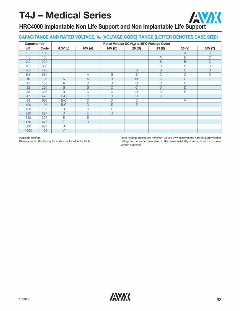
63102617
T4J – Medical SeriesHRC4000 Implantable Non Life Support and Non Implantable Life Support
Capacitance Rated Voltage DC (VR) to 85°C (Voltage Code) μF Code 6.3V (J) 10V (A) 16V (C) 20 (D) 25 (E) 35 (V) 50V (T) 1.0 105 A C 1.5 155 A B C 2.2 225 B B C 3.3 335 B B C 4.7 475 B B C D 6.8 685 A B B C C D 10 106 A A B B/C C C E 15 156 A B B C C D 22 226 B B C C D D 33 336 B C C D D E 47 476 B/C C D D D 68 686 B/C C D E V 100 107 B/C D E E 150 157 D D E 220 227 D E U 330 337 E E 470 477 E U 680 687 U 1000 108 V
CAPACITANCE AND RATED VOLTAGE, VR (VOLTAGE CODE) RANGE (LETTER DENOTES CASE SIZE)
Available RatingsPlease contact the factory for codes not listed in the table.
Note: Voltage ratings are minimum values. AVX reserves the right to supply higherratings in the same case size, to the same reliability standards with customer written approval.
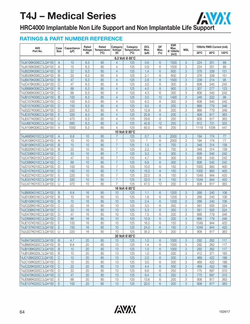
64 102617
T4J – Medical SeriesHRC4000 Implantable Non Life Support and Non Implantable Life Support
RATINGS & PART NUMBER REFERENCE Rated Rated Category Category DCL DF ESR 100kHz RMS Current (mA) AVX Case Capacitance Voltage Temperature Voltage Temperature Max. Max. Max. MSL Part No. Size (μF) (V) (ºC) (V) (ºC) (μA) (%) @ 100kHz 25ºC 85ºC 125ºC (mΩ)
6.3 Volt @ 85°CT4JA106K006C�LQ4^00 A 10 6.3 85 4 125 0.6 6 1500 3 224 201 89T4JA156K006C�LQ4^00 A 15 6.3 85 4 125 0.9 6 1500 3 224 201 89T4JB226K006C�LQ4^00 B 22 6.3 85 4 125 1.4 6 600 3 376 339 151T4JB336K006C�LQ4^00 B 33 6.3 85 4 125 2.1 6 600 3 376 339 151T4JB476K006C�LQ4^00 B 47 6.3 85 4 125 2.8 8 1500 3 238 214 95T4JC476K006C�LQ4^00 C 47 6.3 85 4 125 3.0 6 300 3 606 545 242T4JB686K006C�LQ4^00 B 68 6.3 85 4 125 4.0 8 900 3 307 277 123T4JC686K006C�LQ4^00 C 68 6.3 85 4 125 4.3 6 300 3 606 545 242T4JB107K006C�LQ4^00 B 100 6.3 85 4 125 3.0 10 1400 3 246 222 99T4JC107K006C�LQ4^00 C 100 6.3 85 4 125 6.3 6 300 3 606 545 242T4JD157K006C�LQ4^00 D 150 6.3 85 4 125 9.5 6 200 3 866 779 346T4JD227K006C�LQ4^00 D 220 6.3 85 4 125 13.9 8 200 3 866 779 346T4JE337K006C�LQ4^00 E 330 6.3 85 4 125 20.8 8 200 3 908 817 363T4JE477K006C�LQ4^00 E 470 6.3 85 4 125 29.6 8 200 3 908 817 363T4JU687K006C�LQ4^00 U 680 6.3 85 4 125 42.8 12 250 3 812 731 325T4JV108K006C�LQ4^00 V 1000 6.3 85 4 125 60.0 16 200 3 1118 1006 447
10 Volt @ 85°CT4JA685K010C�LQ4^00 A 6.8 10 85 7 125 0.7 6 2000 3 194 174 77T4JA106K010C�LQ4^00 A 10 10 85 7 125 1 6 2000 3 194 174 77T4JB156K010C�LQ4^00 B 15 10 85 7 125 1.5 6 700 3 348 314 139T4JB226K010C�LQ4^00 B 22 10 85 7 125 2.2 6 700 3 348 314 139T4JC336K010C�LQ4^00 C 33 10 85 7 125 3.3 6 300 3 606 545 242T4JC476K010C�LQ4^00 C 47 10 85 7 125 4.7 6 300 3 606 545 242T4JC686K010C�LQ4^00 C 68 10 85 7 125 6.8 6 300 3 606 545 242T4JD107K010C�LQ4^00 D 100 10 85 7 125 10.0 6 150 3 1000 900 400T4JD157K010C�LQ4^00 D 150 10 85 7 125 15.0 8 150 3 1000 900 400T4JE227K010C�LQ4^00 E 220 10 85 7 125 22.0 8 150 3 1049 944 420T4JE337K010C�LQ4^00 E 330 10 85 7 125 33.0 8 150 3 1049 944 420T4JU477K010C�LQ4^00 U 470 10 85 7 125 47.0 12 200 3 908 817 363
16 Volt @ 85°CT4JB685K016C�LQ4^00 B 6.8 16 85 10 125 1.1 6 1200 3 266 240 106T4JB106K016C�LQ4^00 B 10 16 85 10 125 1.6 6 1200 3 266 240 106T4JB156K016C�LQ4^00 B 15 16 85 10 125 2.4 6 1200 3 266 240 106T4JC226K016C�LQ4^00 C 22 16 85 10 125 3.5 6 350 3 561 505 224T4JC336K016C�LQ4^00 C 33 16 85 10 125 5.3 6 350 3 561 505 224T4JD476K016C�LQ4^00 D 47 16 85 10 125 7.5 6 200 3 866 779 346T4JD686K016C�LQ4^00 D 68 16 85 10 125 10.9 6 200 3 866 779 346T4JE107K016C�LQ4^00 E 100 16 85 10 125 16.0 6 150 3 1049 944 420T4JE157K016C�LQ4^00 E 150 16 85 10 125 24.0 6 150 3 1049 944 420T4JU227K016C�LQ4^00 U 220 16 85 10 125 35.2 12 200 3 908 817 363
20 Volt @ 85°CT4JB475K020C�LQ4^00 B 4.7 20 85 13 125 1.0 6 1000 3 292 262 117T4JB685K020C�LQ4^00 B 6.8 20 85 13 125 1.4 6 1000 3 292 262 117T4JB106K020C�LQ4^00 B 10 20 85 13 125 1.0 6 1000 3 292 262 117 T4JB106K020L�LQ4^00 B 10 20 85 13 125 1.0 6 500 3 412 371 165T4JC106K020C�LQ4^00 C 10 20 85 13 125 2.0 6 500 3 469 422 188T4JC156K020C�LQ4^00 C 15 20 85 13 125 3.0 6 500 3 469 422 188T4JC226K020C�LQ4^00 C 22 20 85 13 125 4.4 6 500 3 469 422 188T4JD336K020C�LQ4^00 D 33 20 85 13 125 6.6 6 250 3 775 697 310T4JD476K020C�LQ4^00 D 47 20 85 13 125 9.4 6 250 3 775 697 310T4JE686K020C�LQ4^00 E 68 20 85 13 125 13.6 6 200 3 908 817 363T4JE107K020C�LQ4^00 E 100 20 85 13 125 20.0 6 200 3 908 817 363

65102617
T4J – Medical SeriesHRC4000 Implantable Non Life Support and Non Implantable Life Support
Moisture Sensitivity Level (MSL) is defined according to J-STD-020.All technical data relates to an ambient temperature of +25°C. Capacitance and DF are measured at 120Hz, 0.5V RMS with a maximum DC bias of 2.2 volts. DCL ismeasured at rated voltage after 5 minutes.The EIA & CECC standards for low ESR Solid Tantalum Capacitors allow an ESR movement to 1.25 times catalogue limit post mounting.
Rated Rated Category Category DCL DF ESR 100kHz RMS Current (mA) AVX Case Capacitance Voltage Temperature Voltage Temperature Max. Max. Max. MSL Part No. Size (μF) (V) (ºC) (V) (ºC) (μA) (%) @ 100kHz 25ºC 85ºC 125ºC (mΩ)
25 Volt @ 85°CT4JA155K025C�LQ4^00 A 1.5 25 85 17 125 0.4 6 3000 3 158 142 63T4JB225K025C�LQ4^00 B 2.2 25 85 17 125 0.6 6 2000 3 206 186 82T4JB335K025C�LQ4^00 B 3.3 25 85 17 125 0.8 6 2000 3 206 186 82T4JB475K025C�LQ4^00 B 4.7 25 85 17 125 1.2 6 2000 3 206 186 82T4JC685K025C�LQ4^00 C 6.8 25 85 17 125 1.7 6 600 3 428 385 171T4JC106K025C�LQ4^00 C 10 25 85 17 125 2.5 6 600 3 428 385 171T4JC156K025C�LQ4^00 C 15 25 85 17 125 3.8 6 600 3 428 385 171T4JD226K025C�LQ4^00 D 22 25 85 17 125 5.5 6 400 3 612 551 245T4JD336K025C�LQ4^00 D 33 25 85 17 125 8.3 6 400 3 612 551 245T4JD476K025C� LQ4^00 D 47 25 85 17 125 11.8 6 400 3 612 551 245
35 Volt @ 85°CT4JA105K035C�LQ4^00 A 1.0 35 85 23 125 0.4 6 3000 3 158 142 63 T4JA105K035L�LQ4^00 A 1.0 35 85 23 125 0.2 6 1000 3 274 246 110T4JB155K035C�LQ4^00 B 1.5 35 85 23 125 0.5 6 2500 3 184 166 74T4JB225K035C�LQ4^00 B 2.2 35 85 23 125 0.8 6 2500 3 184 166 74T4JB335K035C�LQ4^00 B 3.3 35 85 23 125 1.2 6 2500 3 184 166 74T4JC475K035C�LQ4^00 C 4.7 35 85 23 125 1.6 6 600 3 428 385 171T4JC685K035C�LQ4^00 C 6.8 35 85 23 125 2.4 6 600 3 428 385 171T4JC106K035C�LQ4^00 C 10 35 85 23 125 3.5 6 600 3 428 385 171T4JD156K035C�LQ4^00 D 15 35 85 23 125 5.3 6 400 3 612 551 245T4JD226K035C�LQ4^00 D 22 35 85 23 125 7.7 6 400 3 612 551 245T4JE336K035C�LQ4^00 E 33 35 85 23 125 11.6 6 250 3 812 731 325T4JV686K035C�LQ4^00 V 68 35 85 23 125 23.8 6 500 3 707 636 283
50 Volt @ 85°CT4JC105K050C�LQ4^00 C 1 50 85 33 125 0.5 4 1500 3 271 244 108T4JC155K050C�LQ4^00 C 1.5 50 85 33 125 0.8 6 1500 3 271 244 108T4JC225K050C�LQ4^00 C 2.2 50 85 33 125 1.1 6 1500 3 271 244 108T4JC335K050C�LQ4^00 C 3.3 50 85 33 125 1.7 6 1500 3 271 244 108T4JD475K050C�LQ4^00 D 4.7 50 85 33 125 2.4 4.5 600 3 500 450 200T4JD685K050C�LQ4^00 D 6.8 50 85 33 125 3.4 4.5 600 3 500 450 200T4JE106K050C�LQ4^00 E 10 50 85 33 125 5.0 4.5 400 3 642 578 257
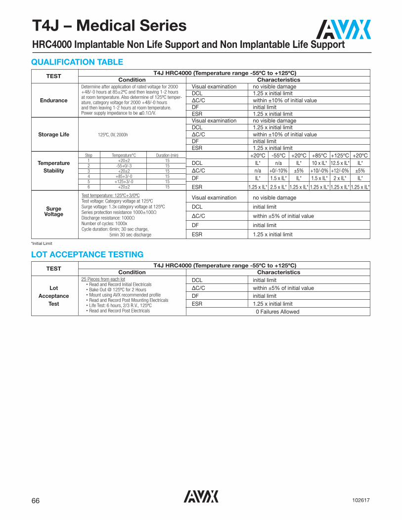
66 102617
T4J – Medical SeriesHRC4000 Implantable Non Life Support and Non Implantable Life Support
QUALIFICATION TABLE
TEST T4J HRC4000 (Temperature range -55ºC to +125ºC)Condition Characteristics
Visual examination no visible damageDCL 1.25 x initial limit
Endurance ΔC/C within ±10% of initial valueDF initial limitESR 1.25 x initial limitVisual examination no visible damageDCL 1.25 x initial limit
Storage Life 125ºC, 0V, 2000h ΔC/C within ±10% of initial valueDF initial limitESR 1.25 x initial limit
+20ºC -55ºC +20ºC +85ºC +125ºC +20ºCTemperature DCL IL* n/a IL* 10 x IL* 12.5 x IL* IL*
Stability ΔC/C n/a +0/-10% ±5% +10/-0% +12/-0% ±5%DF IL* 1.5 x IL* IL* 1.5 x IL* 2 x IL* IL*
ESR 1.25 x IL* 2.5 x IL* 1.25 x IL* 1.25 x IL* 1.25 x IL* 1.25 x IL*
Visual examination no visible damage
Surge DCL initial limitVoltage ΔC/C within ±5% of initial value
DF initial limit
ESR 1.25 x initial limit
Determine after application of rated voltage for 2000+48/-0 hours at 85±2ºC and then leaving 1-2 hoursat room temperature. Also determine of 125ºC temper-ature, category voltage for 2000 +48/-0 hours and then leaving 1-2 hours at room temperature.Power supply impedance to be ≤0.1Ω/V.
Test temperature: 125ºC+3/0ºCTest voltage: Category voltage at 125ºCSurge voltage: 1.3x category voltage at 125ºCSeries protection resistance 1000±100ΩDischarge resistance: 1000ΩNumber of cycles: 1000xCycle duration: 6min; 30 sec charge,
5min 30 sec discharge
Step Temperature°C Duration (min)1 +20±2 152 -55+0/-3 153 +20±2 154 +85+3/-0 155 +125+3/-0 156 +20±2 15
*Initial Limit
LOT ACCEPTANCE TESTING
TEST T4J HRC4000 (Temperature range -55ºC to +125ºC)Condition Characteristics
DCL initial limitLot ΔC/C within ±5% of initial value
Acceptance DF initial limitTest ESR 1.25 x initial limit
0 Failures Allowed
25 Pieces from each lot• Read and Record Initial Electricals• Bake Out @ 125ºC for 2 Hours• Mount using AVX recommended profile• Read and Record Post Mounting Electricals• Life Test: 6 hours, 2/3 R.V., 125ºC• Read and Record Post Electricals
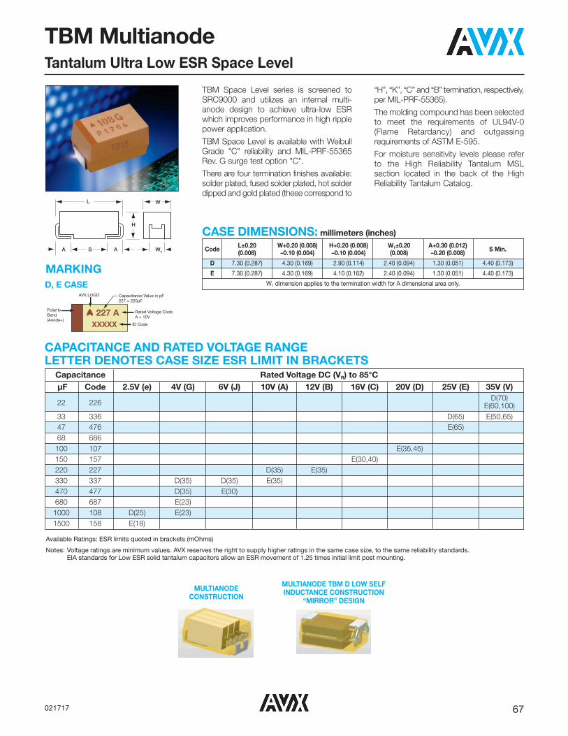
67021717
TBM MultianodeTantalum Ultra Low ESR Space Level
TBM Space Level series is screened toSRC9000 and utilizes an internal multi-anode design to achieve ultra-low ESRwhich improves performance in high ripplepower application.
TBM Space Level is available with WeibullGrade "C" reliability and MIL-PRF-55365Rev. G surge test option "C".
There are four termination finishes available:solder plated, fused solder plated, hot solderdipped and gold plated (these correspond to
“H”, “K”, “C” and “B” termination, respectively,per MIL-PRF-55365).
The molding compound has been selectedto meet the requirements of UL94V-0(Flame Retardancy) and outgassingrequirements of ASTM E-595.
For moisture sensitivity levels please referto the High Reliability Tantalum MSLsection located in the back of the HighReliability Tantalum Catalog.
L
SA A W1
W
H
Code L±0.20 W+0.20 (0.008) H+0.20 (0.008) W1±0.20 A+0.30 (0.012) S Min. (0.008) –0.10 (0.004) –0.10 (0.004) (0.008) –0.20 (0.008)
D 7.30 (0.287) 4.30 (0.169) 2.90 (0.114) 2.40 (0.094) 1.30 (0.051) 4.40 (0.173)
E 7.30 (0.287) 4.30 (0.169) 4.10 (0.162) 2.40 (0.094) 1.30 (0.051) 4.40 (0.173)
W1 dimension applies to the termination width for A dimensional area only.
CASE DIMENSIONS: millimeters (inches)
Capacitance Rated Voltage DC (VR) to 85°C μF Code 2.5V (e) 4V (G) 6V (J) 10V (A) 12V (B) 16V (C) 20V (D) 25V (E) 35V (V)
22 226 D(70)
E(60,100) 33 336 D(65) E(50,65) 47 476 E(65) 68 686 100 107 E(35,45) 150 157 E(30,40) 220 227 D(35) E(35) 330 337 D(35) D(35) E(35) 470 477 D(35) E(30) 680 687 E(23) 1000 108 D(25) E(23) 1500 158 E(18)
CAPACITANCE AND RATED VOLTAGE RANGE LETTER DENOTES CASE SIZE ESR LIMIT IN BRACKETS
Available Ratings: ESR limits quoted in brackets (mOhms)
Notes: Voltage ratings are minimum values. AVX reserves the right to supply higher ratings in the same case size, to the same reliability standards.EIA standards for Low ESR solid tantalum capacitors allow an ESR movement of 1.25 times initial limit post mounting.
D, E CASE
XXXXX
227 A
AVX LOGO Capacitance Value in pF227 = 220µF
Rated Voltage CodeA = 10V
ID Code
PolarityBand (Anode+)
MARKING
MULTIANODE CONSTRUCTION
MULTIANODE TBM D LOW SELF INDUCTANCE CONSTRUCTION
“MIRROR” DESIGN

68 021717
TBM MultianodeTantalum Ultra Low ESR Space Level
TBM
Type
*
CapacitanceTolerance
M = ±20% K = ±10%
�
Packaging B = Bulk R = 7" T&R S = 13" T&RW = Waffle
See page 8for additionalpackagingoptions.
++
Surge TestOption
45 = 10 cycles, -55ºC & +85ºCbefore Weibull
E
CaseSize
L
Standard orLow ESR
RangeC = Std ESRL = Low ESR
L
Inspection LevelL = Group A
006
VoltageCode
002 = 2.5Vdc004 = 4Vdc006 = 6Vdc010 = 10Vdc012 = 12Vdc016 = 16Vdc020 = 20Vdc025 = 25Vdc035 = 35Vdc
477
CapacitanceCode
pF code: 1st two digits
representsignificant figures 3rd
digit representsmultiplier
(number ofzeros to follow)
@
Reliability GradeWeibull: C = 0.01%/1000 hrs.
90% conf.
9
QualificationLevel
9 = SRC9000
^
Termination FinishH = Solder Plated0 = Fused Solder
Plated8 = Hot Solder
Dipped9 = Gold Plated
Technical Data: Unless otherwise specified, all technical data relate to an ambient temperature of +25°CCapacitance Range: 22 μF to 1500 μFCapacitance Tolerance: ±10%; ±20%Rated Voltage DC (VR) � +85°C: 2.5 4 6 10 12 16 20 25 35Category Voltage (VC) � +125°C: 1.7 2.7 4 7 8.4 10 13 17 23Surge Voltage (VS) � +85°C: 3.3 5.2 8 13 15.6 20 26 32 46Surge Voltage (VS) � +125°C: 2.2 3.4 5 8 9.6 12 16 20 28Temperature Range: -55°C to +125°C
TECHNICAL SPECIFICATIONS
HOW TO ORDERSPACE LEVEL OPTIONS TO SRC9000:
LEAD-FREE COMPATIBLECOMPONENT
For RoHS compliant products, please select correct termination style.

69021717
TBM MultianodeTantalum Ultra Low ESR Space Level
All technical data relates to an ambient temperature of +25°C. Capacitance and DF are measured at 120Hz, 0.5V RMS with a maximum DC bias of 2.2 volts. DCL is measured at rated voltage after 5 minutes.
NOTE: AVX reserves the right to supply a higher voltage rating or tighter tolerance part in the same case size, to the same reliability standards.
Parametric Specifications by Rating Typical RMS Ripple Data by RatingCap DC Rated ESR DCL max DF max Power 25ºC 85ºC 125ºC 25ºC 85ºC 125ºC
@ 120Hz Voltage @ 100kHz +25°C +85°C +125°C +25°C +(85/125)°C -55°C Dissipation Ripple Ripple Ripple Ripple Ripple Ripple
AVX P/N Case μF @ V @ mOhms (μA) (μA) (μA) (%) (%) (%) W A A A V V V25ºC +85ºC @ +25ºC (100kHz) (100kHz) (100kHz) (100kHz) (100kHz) (100kHz)
2.5 Volt @ 85ºC (1.7 Volt @ 125ºC)TBMD108*002L�LC9^45 D 1000 2.5 25 18.8 188 376 8 11 12 0.255 3.194 2.874 1.277 0.080 0.072 0.032TBME158*002C�LC9^45 E 1500 2.5 18 28.1 281 562 6 9 10 0.270 3.873 3.486 1.549 0.070 0.063 0.028
4 Volt @ 85ºC (2.7 Volt @ 125ºC)TBMD337*004L�LC9^45 D 330 4 35 9.9 99 198 8 11 12 0.255 2.699 2.429 1.080 0.094 0.085 0.038TBMD477*004L�LC9^45 D 470 4 35 14.1 141 282 8 11 12 0.255 2.699 2.429 1.080 0.094 0.085 0.038TBME687*004C�LC9^45 E 680 4 23 20.4 204 408 6 9 10 0.270 3.426 3.084 1.370 0.079 0.071 0.032TBME108*004C�LC9^45 E 1000 4 23 30 300 600 6 9 10 0.270 3.426 3.084 1.370 0.079 0.071 0.032
6 Volt @ 85ºC (4 Volt @ 125ºC)TBMD337*006L�LC9^45 D 330 6 35 14.9 149 298 8 11 12 0.255 2.699 2.429 1.080 0.094 0.085 0.038TBME477*006C�LC9^45 E 470 6 30 21.2 212 424 6 9 10 0.270 3.000 2.700 1.200 0.090 0.081 0.036
10 Volt @ 85ºC (7 Volt @ 125ºC)TBMD227*010L�LC9^45 D 220 10 35 16.5 165 330 8 11 12 0.255 2.699 2.429 1.080 0.094 0.085 0.038TBME337*010C�LC9^45 E 330 10 35 24.8 248 496 6 9 10 0.270 2.777 2.500 1.111 0.097 0.087 0.039
12 Volt @ 85ºC (8.4 Volt @ 125ºC)TBME227*012C�LC9^45 E 220 12 35 19.8 198 396 6 9 10 0.270 2.777 2.500 1.111 0.097 0.087 0.039
16 Volt @ 85ºC (10 Volt @ 125ºC)TBME157*016L�LC9^45 E 150 16 30 18 180 360 6 9 10 0.270 3.000 2.700 1.200 0.090 0.081 0.036TBME157*016C�LC9^45 E 150 16 40 18 180 360 6 9 10 0.270 2.598 2.338 1.039 0.104 0.094 0.042
20 Volt @ 85ºC (13 Volt @ 125ºC)TBME107*020L�LC9^45 E 100 20 35 15 150 300 6 9 10 0.270 2.777 2.500 1.111 0.097 0.087 0.039TBME107*020C�LC9^45 E 100 20 45 15 150 300 6 9 10 0.270 2.449 2.205 0.980 0.110 0.099 0.044
25 Volt @ 85ºC (17 Volt @ 125ºC)TBMD336*025L�LC9^45 D 33 25 65 6.2 62 124 8 11 12 0.255 1.981 1.783 0.792 0.129 0.116 0.051TBME476*025L�LC9^45 E 47 25 65 8.8 88 176 6 9 10 0.270 2.038 1.834 0.815 0.132 0.119 0.053
35 Volt @ 85ºC (23 Volt @ 125ºC)TBMD226*035L�LC9^45 D 22 35 70 5.8 58 116 8 11 12 0.255 1.909 1.718 0.763 0.134 0.120 0.053TBME226*035L�LC9^45 E 22 35 60 5.8 58 116 6 9 10 0.270 2.121 1.909 0.849 0.127 0.115 0.051TBME226*035C�LC9^45 E 22 35 100 5.8 58 116 6 9 10 0.270 1.643 1.479 0.657 0.164 0.148 0.066TBME336*035L�LC9^45 E 33 35 50 8.7 87 174 6 9 10 0.270 2.324 2.091 0.930 0.116 0.105 0.046TBME336*035C�LC9^45 E 33 35 65 8.7 87 174 6 9 10 0.270 2.038 1.834 0.815 0.132 0.119 0.053
RATING & PART NUMBER REFERENCE

70 021717
TBM MultianodeTantalum Ultra Low ESR COTS-Plus
TBM COTS-Plus series uses an internalmulti-anode design to achieve ultra-lowESR which improves performance in highripple power applications.
TBM is available with Weibull Grade “B” re-liability and all MIL-PRF-55365 Rev. G surgetest options (“A”, “B” & “C”).
There are four termination finishes available: solder plated, fused solder plated,hot solder dipped and gold plated (these
correspond to “H”, “K”, “C” and “B” termi-nation, respectively, per MIL-PRF-55365).
The molding compound has been selectedto meet the requirements of UL94V-0(Flame Retardancy) and outgassing require-ments of ASTM E-595.
For moisture sensitivity levels please refer tothe High Reliability Tantalum MSL section lo-cated in the back of the High Reliability Tan-talum Catalog.
L
SA A W1
W
H
Code L±0.20 W+0.20 (0.008) H+0.20 (0.008) W1±0.20 A+0.30 (0.012) S Min. (0.008) –0.10 (0.004) –0.10 (0.004) (0.008) –0.20 (0.008)
D 7.30 (0.287) 4.30 (0.169) 2.90 (0.114) 2.40 (0.094) 1.30 (0.051) 4.40 (0.173)
E 7.30 (0.287) 4.30 (0.169) 4.10 (0.162) 2.40 (0.094) 1.30 (0.051) 4.40 (0.173)
V 7.30 (0.287) 6.10 (0.240) 3.55 (0.140) 3.10 (0.120) 1.30 (0.051) 4.40 (0.173)
W1 dimension applies to the termination width for A dimensional area only.
CASE DIMENSIONS: millimeters (inches)
Capacitance Rated Voltage DC (VR) to 85°C μF Code 2.5V (e) 4V (G) 6V (J) 10V (A) 12V (B) 16V (C) 20V (D) 25V (E) 35V (V)
22 226 D(70)
E(60,100) 33 336 D(65) E(50,65) 47 476 E(65) E(55) 68 686 E(45) 100 107 E(35,45) 150 157 E(30,40) 220 227 D(35) E(35) E(25) 330 337 D(35) D(35) E(23,35) 470 477 D(35) E(18,30) E(23) 680 687 E(18,23) E(18), V(23) 1000 108 D(25) E(18,23) V(18) 1500 158 E(12,18) E(15) 2000 208
CAPACITANCE AND RATED VOLTAGE RANGE LETTER DENOTES CASE SIZE ESR LIMIT IN BRACKETS
Available Ratings: ESR limits quoted in brackets (mOhms)
Notes: Voltage ratings are minimum values. AVX reserves the right to supply higher ratings in the same case size, to the same reliability standards.EIA standards for Low ESR solid tantalum capacitors allow an ESR movement of 1.25 times initial limit post mounting.
D, E, V CASE
XXXXX
227 A
AVX LOGO Capacitance Value in pF227 = 220µF
Rated Voltage CodeA = 10V
ID Code
PolarityBand (Anode+)
MARKING
MULTIANODE CONSTRUCTION
MULTIANODE TBM D LOW SELF INDUCTANCE CONSTRUCTION
“MIRROR” DESIGN

71021717
TBM MultianodeTantalum Ultra Low ESR COTS-Plus
*
CapacitanceTolerance
M = ±20% K = ±10%
�
Packaging B = Bulk R = 7" T&R S = 13" T&RW = Waffle
See page 8for additionalpackagingoptions.
++
Surge TestOption
00 = None23 = 10 Cycles, +25ºC24 = 10 Cycles,
-55ºC & +85ºC45 = 10 cycles,
-55ºC & +85ºCbefore Weibull
TBM
Type
E
CaseSize
L
Standard orLow ESR
RangeC = Std ESRL = Low ESR
#
Inspection LevelS = Std.
ConformanceL = Group A
HOW TO ORDERCOTS-PLUS:
006
VoltageCode
002 = 2.5Vdc004 = 4Vdc006 = 6Vdc010 = 10Vdc012 = 12Vdc016 = 16Vdc020 = 20Vdc025 = 25Vdc035 = 35Vdc
477
CapacitanceCode
pF code: 1st two digits
representsignificant figures 3rd
digit representsmultiplier
(number ofzeros to follow)
@
Reliability GradeWeibull: B = 0.1%/1000 hrs.
90% conf.Z = Non-ER
^
Termination FinishH = Solder Plated0 = Fused Solder
Plated8 = Hot Solder
Dipped9 = Gold Plated7 = Matte Sn
Technical Data: Unless otherwise specified, all technical data relate to an ambient temperature of +25°CCapacitance Range: 22 μF to 1500 μFCapacitance Tolerance: ±10%; ±20%Rated Voltage DC (VR) � +85°C: 2.5 4 6 10 12 16 20 25 35Category Voltage (VC) � +125°C: 1.7 2.7 4 7 8.4 10 13 17 23Surge Voltage (VS) � +85°C: 3.3 5.2 8 13 15.6 20 26 32 46Surge Voltage (VS) � +125°C: 2.2 3.4 5 8 9.6 12 16 20 28Temperature Range: -55°C to +125°C
TECHNICAL SPECIFICATIONS
0
QualificationLevel
0 = N/A
LEAD-FREE COMPATIBLECOMPONENT
For RoHS compliant products, please select correct termination style.

72 021717
TBM MultianodeTantalum Ultra Low ESR COTS-Plus
All technical data relates to an ambient temperature of +25°C. Capacitance and DF are measured at 120Hz, 0.5V RMS with a maximum DC bias of 2.2 volts. DCL is measured at rated voltage after 5 minutes.
NOTE: AVX reserves the right to supply a higher voltage rating or tighter tolerance part in the same case size, to the same reliability standards.
Parametric Specifications by Rating Typical RMS Ripple Data by Rating
Cap DC Rated ESR DCL max DF max Power 25ºC 85ºC 125ºC 25ºC 85ºC 125ºC
@ 120Hz Voltage @ 100kHz +25°C +85°C +125°C +25°C +85/125°C -55°C Dissipation Ripple Ripple Ripple Ripple Ripple RippleCurrent Current Current Voltage Voltage Voltage
AVX P/N Case μF @ V @ mOhms (μA) (μA) (μA) (%) (%) (%) W A A A V V V25ºC +85ºC @ +25ºC (100kHz) (100kHz) (100kHz) (100kHz) (100kHz) (100kHz)
2.5 Volt @ 85°C (1.7 Volt @ 125°C)TBMD108*002L�SB0^++ D 1000 2.5 25 18.8 188 376 8 11 12 0.255 3.194 2.874 1.277 0.080 0.072 0.032TBME158*002C�SB0^++ E 1500 2.5 18 28.1 281 562 6 9 10 0.270 3.873 3.486 1.549 0.070 0.063 0.028TBME158*002L�SB0^++ E 1500 2.5 12 38 380 760 6 9 10 0.270 4.743 4.269 1.897 0.057 0.051 0.023
4 Volt @ 85°C (2.7 Volt @ 125°C)TBMD337*004L�SB0^++ D 330 4 35 9.9 99 198 8 11 12 0.255 2.699 2.429 1.080 0.094 0.085 0.038TBMD477*004L�SB0^++ D 470 4 35 14.1 141 282 8 11 12 0.255 2.699 2.429 1.080 0.094 0.085 0.038TBME687*004C�SB0^++ E 680 4 23 20.4 204 408 6 9 10 0.270 3.426 3.084 1.370 0.079 0.071 0.032TBME687*004L�SB0^++ E 680 4 18 27 270 540 6 9 10 0.270 3.873 3.486 1.549 0.070 0.063 0.028TBME108*004C�SB0^++ E 1000 4 23 30 300 600 6 9 10 0.270 3.426 3.084 1.370 0.079 0.071 0.032TBME108*004L�SB0^++ E 1000 4 18 40 400 800 6 9 10 0.270 3.873 3.486 1.549 0.070 0.063 0.028TBMV108*004L�SB0^++ V 1000 4 18 40 400 800 6 9 10 0.285 3.979 3.581 1.592 0.072 0.064 0.029TBME158*004L�SB0^++ E 1500 4 15 40 400 800 6 9 10 0.270 4.243 3.818 1.697 0.064 0.057 0.025
6 Volt @ 85°C (4 Volt @ 125°C)TBMD337*006L�SB0^++ D 330 6 35 14.9 149 298 8 11 12 0.255 2.699 2.429 1.080 0.094 0.085 0.038TBME477*006C�SB0^++ E 470 6 30 21.2 212 424 6 9 10 0.270 3.000 2.700 1.200 0.090 0.081 0.036TBME477*006L�SB0^++ E 470 6 18 28 280 560 6 9 10 0.270 3.873 3.486 1.549 0.070 0.063 0.028TBME687*006L�SB0^++ E 680 6 18 41 410 820 6 9 10 0.270 3.873 3.486 1.549 0.070 0.063 0.028TBMV687*006L�SB0^++ V 680 6 23 41 410 820 6 9 10 0.285 3.520 3.168 1.408 0.081 0.073 0.032
10 Volt @ 85°C (7 Volt @ 125°C)TBMD227*010L�SB0^++ D 220 10 35 16.5 165 330 8 11 12 0.255 2.699 2.429 1.080 0.094 0.085 0.038TBME337*010C�SB0^++ E 330 10 35 24.8 248 496 6 9 10 0.270 2.777 2.500 1.111 0.097 0.087 0.039TBME337*010L�SB0^++ E 330 10 23 33 330 660 6 9 10 0.270 3.426 3.084 1.370 0.079 0.071 0.032TBME477*010L�SB0^++ E 470 10 23 47 470 940 6 9 10 0.270 3.426 3.084 1.370 0.079 0.071 0.032
12 Volt @ 85°C (8.4 Volt @ 125°C)TBME227*012C�SB0^++ E 220 12 35 19.8 198 396 6 9 10 0.270 2.777 2.500 1.111 0.097 0.087 0.039
16 Volt @ 85°C (10 Volt @ 125°C)TBME157*016C�SB0^++ E 150 16 40 18 180 360 6 9 10 0.270 2.598 2.338 1.039 0.104 0.094 0.042TBME157*016L�SB0^++ E 150 16 30 18 180 360 6 9 10 0.270 3.000 2.700 1.200 0.090 0.081 0.036TBME227*016L�SB0^++ E 220 16 25 35 350 700 6 9 10 0.270 3.286 2.958 1.315 0.082 0.074 0.033
20 Volt @ 85°C (13 Volt @ 125°C)TBME107*020C�SB0^++ E 100 20 45 15 150 300 6 9 10 0.270 2.449 2.205 0.980 0.110 0.099 0.044TBME107*020L�SB0^++ E 100 20 35 15 150 300 6 9 10 0.270 2.777 2.500 1.111 0.097 0.087 0.039
25 Volt @ 85°C (17 Volt @ 125°C)TBMD336*025L�SB0^++ D 33 25 65 6.2 62 124 8 11 12 0.255 1.981 1.783 0.792 0.129 0.116 0.051TBME476*025L�SB0^++ E 47 25 65 8.8 88 176 6 9 10 0.270 2.038 1.834 0.815 0.132 0.119 0.053TBME686*025L�SB0^++ E 68 25 45 17 170 340 6 9 10 0.270 2.449 2.205 0.980 0.110 0.099 0.044
35 Volt @ 85°C (23 Volt @ 125°C)TBMD226*035L�SB0^++ D 22 35 70 5.8 58 116 8 11 12 0.255 1.909 1.718 0.763 0.134 0.120 0.053TBME226*035C�SB0^++ E 22 35 100 5.8 58 116 6 9 10 0.270 1.643 1.479 0.657 0.164 0.148 0.066TBME226*035L�SB0^++ E 22 35 60 5.8 58 116 6 9 10 0.270 2.121 1.909 0.849 0.127 0.115 0.051TBME336*035C�SB0^++ E 33 35 65 8.7 87 174 6 9 10 0.270 2.038 1.834 0.815 0.132 0.119 0.053TBME336*035L�SB0^++ E 33 35 50 8.7 87 174 6 9 10 0.270 2.324 2.091 0.930 0.116 0.105 0.046TBME476*035L�SB0^++ E 47 35 55 16 160 320 6 9 10 0.270 2.216 1.994 0.886 0.122 0.110 0.049
RATING & PART NUMBER REFERENCE

73041416
Case Length (L) Width (W) Height (H)
Term. Width (W1)Code
A
3.20±0.20 1.60±0.20 1.60±0.20 0.15+0.35/-0.00 (0.126±0.008) (0.063±0.008) (0.063±0.008) (0.006+0.014/-0.000)
L
1.60+0.25/-0.15 0.84+0.20/-0.10 0.84+0.20/-0.10 0.15+0.35/-0.00 (0.063+0.010/-0.006) (0.033+0.008/-0.004) (0.033+0.008/-0.004) (0.006+0.014/-0.000)
R
2.00+0.25/-0.15 1.35+0.20/-0.10 1.35+0.20/-0.10 0.15+0.35/-0.00 (0.079+0.010/-0.006) (0.053+0.008/-0.004) (0.053+0.008/-0.004) (0.006+0.014/-0.000)
TBC SeriesCWR15 MIL-PRF-55365/12 Established Reliability, COTS-Plus & Space Level
AVX announces the world’s smallestmilitary approved tantalum chip capac-itors. The CWR15 offers 0603, 0805and 1206 case sizes in capacitance/ voltage combinations previously onlyavailable in much larger packages. Therevolutionary AVX TACmicrochip® tech-nology offers designers significant op-portunity to downsize circuits formilitary and aerospace applications.
The product is manufactured in the AVXTantalum high reliability facility in Bidde-ford, Maine which is also home to theCWR09, CWR11, CWR19 and CWR29product lines.For moisture sensitivity levels pleaserefer to the High Reliability TantalumMSL section located in the back of theHigh Reliability Tantalum Catalog.
CASE DIMENSIONS: millimeters (inches)
H
L
W
PP
POLARITY BAND NOT TOEXCEED 75% OF BODY
Further extensions of the CWR15 product are planned for later in 2009. A new case size will be added, and the voltage range will be extendedto 20 volts. Ratings of 100 μF at 4 volts to 10 μF at 20 volts will be included in this extension of the product line.
Capacitance Voltage Rating DC (VR) at 85°C μF Code 4V (C) 6V (D) 10V (F) 20V (J) 0.47 474 L L 0.68 684 L 1.0 105 L 1.5 155 L 2.2 225 L 3.3 335 L R 4.7 475 L R 6.8 685 L R R 10 106 R R R 15 156 R R A 22 226 R A 33 336 R A 47 476 A 68 686 A
CAPACITANCE AND RATED VOLTAGE, VR (VOLTAGE CODE) RANGE(LETTER DENOTES CASE SIZE)
A, L, R CASE
PolarityBand
(Anode+)
MARKING

74 041416
TBC SeriesCWR15 MIL-PRF-55365/12 Established Reliability, COTS-Plus & Space Level
CWR15 P/N CROSS REFERENCE:
SPACE LEVEL OPTIONS TO SRC9000*:
*
CapacitanceTolerance
M = ±20% K = ±10% J = ±5%
�
Packaging B = Bulk R = 7" T&R S = 13" T&RW = Waffle
See page 8for additionalpackagingoptions.
++
Surge TestOption
00 = None23 = 10 Cycles, +25ºC24 = 10 Cycles,
-55ºC & +85ºC45 = 10 cycles,
-55ºC & +85ºCbefore Weibull
TBC
Type
L
CaseSize
TBC
Type
L
CaseSize
C
Standard orLow ESR
RangeC = Std ESR
#
Inspection LevelS = Std.
ConformanceL = Group A
HOW TO ORDERCOTS-PLUS & MIL QPL (CWR15):
004
VoltageCode
004 = 4Vdc006 = 6Vdc010 = 10Vdc020 = 20Vdc
685
CapacitanceCode
pF code: 1st two digits
representsignificant figures 3rd
digit representsmultiplier
(number ofzeros to follow)
@
Reliability GradeWeibull: B = 0.1%/1000 hrs.
90% conf.C = 0.01%/1000 hrs.
90% conf.D = 0.001%/1000 hrs.
90% conf.Z = Non-ER
^
Termination Finish0 = Fused Solder
Plated9 = Gold Plated7 = Matte Sn
(COTS-Plusonly)
M = MIL (JAN)CWR15
9 = SRC9000
*
CapacitanceTolerance
M = ±20% K = ±10% J = ±5%
�
Packaging B = Bulk R = 7" T&R S = 13" T&RW = Waffle
See page 8for additionalpackagingoptions.
++
Surge TestOption
45 = 10 cycles, -55ºC & +85ºCbefore Weibull
C
Standard orLow ESR
RangeC = Std ESRL = Low ESR
L
Inspection LevelL = Group A
004
VoltageCode
004 = 4Vdc006 = 6Vdc010 = 10Vdc020 = 20Vdc
685
CapacitanceCode
pF code: 1st two digits
representsignificant figures 3rd
digit representsmultiplier
(number ofzeros to follow)
@
Reliability GradeWeibull: B = 0.1%/1000 hrs.
90% conf.C = 0.01%/1000 hrs.
90% conf.D = 0.001%/1000 hrs.
90% conf.
9
QualificationLevel
9 = SRC9000
^
Termination Finish0 = Fused Solder
Plated9 = Gold Plated
*
CapacitanceTolerance
J = ±5% K = ±10% M = ±20%
See page 8 foradditional
packaging op-tions.
+
Surge TestOption
A = +25°C after WeibullB = -55°C & +85°C
after WeibullC = -55°C & +85°C
before WeibullZ = None Required
CWR15
Style
F
VoltageCode
C = 4VdcD = 6Vdc F = 10Vdc J = 20Vdc
C
TerminationFinish
B = Gold PlatedK = Solder Fused
685
CapacitanceCode
pF code: 1st two digits
representsignificant
figures 3rd digitrepresents
number of zerosto follow
–
Product LevelDesignator
Weibull: B = 0.1%/1000 hrs.
90% conf.C = 0.01%/1000 hrs.
90% conf.D = 0.001%/1000 hrs.
90% conf.T = T LevelA = Non-ER
L
Case Size
*Contact factory for AVX SRC9000 Space Level SCD details.
Technical Data: Unless otherwise specified, all technical data relate to an ambient temperature of 25°CCapacitance Range: 0.47 μF to 68 μFCapacitance Tolerance: ±5%; ±10%; ±20%Rated Voltage (VR) � 85°C: 4 6 10 20Category Voltage (VC) � 125°C: 2.7 4 6.7 13.3Surge Voltage (Vs) � 85°C: 5.3 8 13.3 26.7Surge Voltage (Vs) � 125°C: 3.5 5.3 8.7 17.8Temperature Range: -55°C to +125°C
TECHNICAL SPECIFICATIONS
0
QualificationLevel
0 = N/AT = T Level
LEAD-FREE COMPATIBLECOMPONENT
For RoHS compliant products, please select correct termination style.
LEAD-FREE COMPATIBLECOMPONENT
For RoHS compliant products, please select correct termination style.
LEAD-FREE COMPATIBLECOMPONENT
For RoHS compliant products, please select correct termination style.

75041416
TBC SeriesCWR15 MIL-PRF-55365/12 Established Reliability, COTS-Plus & Space Level
All technical data relates to an ambient temperature of +25°C. Capacitance and DF are measured at 120Hz, 0.5V RMS with a maximum DC bias of 2.2 volts. DCL is measured at rated voltage after 5 minutes.
NOTE: AVX reserves the right to supply a higher voltage rating or tighter tolerance part in the same case size, to the same reliability standards.
Parametric Specifications by Rating per MIL-PRF-55365/12 Typical RMS Ripple Data by RatingCap DC Rated ESR DCL max DF Max Power 25ºC 85ºC 125ºC 25ºC 85ºC 125ºC
@ 120Hz Voltage @ 100kHz +25ºC +85ºC +125ºC +25ºC +(85/125)ºC -55ºC Dissipation Ripple Ripple Ripple Ripple Ripple Ripple
CWR15 P/N AVX MIL & COTS-Plus P/N AVX SRC9000 P/N CaseμF V Ohms
(μA) (μA) (μA) (%) (%) (%) WA A A V V V
@ 25ºC @ +85ºC @ +25ºC (100kHz) (100kHz) (100kHz) (100kHz) (100kHz) (100kHz)CWR15CK685*^L+ TBC L 685 * 004 C � # @ 0 ^ + TBC L 685 * 004 C � L @ 9 ^ + L 6.8 4 10 0.5 5 6 8 16 12 0.025 0.05 0.05 0.02 0.50 0.45 0.20CWR15CK106*^R+ TBC R 106 * 004 C � # @ 0 ^ ++ TBC R 106 * 004 C � L @ 9 ^ ++ R 10 4 6 0.5 5 6 8 16 12 0.045 0.09 0.08 0.03 0.52 0.47 0.21CWR15CK156*^R+ TBC R 156 * 004 C � # @ 0 ^ ++ TBC R 156 * 004 C � L @ 9 ^ ++ R 15 4 6 0.6 6 7 8 16 12 0.045 0.09 0.08 0.03 0.52 0.47 0.21CWR15CK226*^R+ TBC R 226 * 004 C � # @ 0 ^ + TBC R 226 * 004 C � L @ 9 ^ + R 22 4 6 0.9 9 11 8 16 12 0.045 0.09 0.08 0.03 0.52 0.47 0.21CWR15CK336*^R+ TBC R 336 * 004 C � # @ 0 ^ + TBC R 336 * 004 C � L @ 9 ^ + R 33 4 6 1.3 13 16 10 20 15 0.045 0.09 0.08 0.03 0.52 0.47 0.21CWR15CK686*^A+ TBC A 686 * 004 C � # @ 0 ^ + TBC A 686 * 004 C � L @ 9 ^ + A 68 4 1 2.7 27 33 15 30 23 0.040 0.20 0.18 0.08 0.20 0.18 0.08CWR15DK335*^L+ TBC L 335 * 006 C � # @ 0 ^ + TBC L 335 * 006 C � L @ 9 ^ + L 3.3 6 10 0.5 5 6 6 12 9 0.025 0.05 0.05 0.02 0.50 0.45 0.20CWR15DK475*^L+ TBC L 475 * 006 C � # @ 0 ^ + TBC L 475 * 006 C � L @ 9 ^ + L 4.7 6 10 0.5 5 6 8 16 12 0.025 0.05 0.05 0.02 0.50 0.45 0.20CWR15DK685*^R+ TBC R 685 * 006 C � # @ 0 ^ ++ TBC R 685 * 006 C � L @ 9 ^ ++ R 6.8 6 6 0.5 5 6 8 16 12 0.045 0.09 0.08 0.03 0.52 0.47 0.21CWR15DK106*^R+ TBC R 106 * 006 C � # @ 0 ^ ++ TBC R 106 * 006 C � L @ 9 ^ ++ R 10 6 6 0.6 6 7 8 16 12 0.045 0.09 0.08 0.03 0.52 0.47 0.21CWR15DK156*^R+ TBC R 156 * 006 C � # @ 0 ^ + TBC R 156 * 006 C � L @ 9 ^ + R 15 6 6 0.9 9 11 8 16 12 0.045 0.09 0.08 0.03 0.52 0.47 0.21CWR15DK226*^A+ TBC A 226 * 006 C � # @ 0 ^ + TBC A 226 * 006 C � L @ 9 ^ + A 22 6 6 1.4 14 17 10 20 15 0.040 0.08 0.07 0.03 0.49 0.44 0.20CWR15DK336*^A+ TBC A 336 * 006 C � # @ 0 ^ + TBC A 336 * 006 C � L @ 9 ^ + A 33 6 6 2 20 24 10 20 15 0.040 0.08 0.07 0.03 0.49 0.44 0.20CWR15DK476*^A+ TBC A 476 * 006 C � # @ 0 ^ + TBC A 476 * 006 C � L @ 9 ^ + A 47 6 4 2.8 28 34 15 30 23 0.040 0.10 0.09 0.04 0.40 0.36 0.16CWR15FK474*^L+ TBC L 474 * 010 C � # @ 0 ^ + TBC L 474 * 010 C � L @ 9 ^ + L 0.47 10 12 0.5 5 6 6 12 9 0.025 0.05 0.04 0.02 0.55 0.49 0.22CWR15FK684*^L+ TBC L 684 * 010 C � # @ 0 ^ + TBC L 684 * 010 C � L @ 9 ^ + L 0.68 10 10 0.5 5 6 6 12 9 0.025 0.05 0.05 0.02 0.50 0.45 0.20CWR15FK105*^L+ TBC L 105 * 010 C � # @ 0 ^ + TBC L 105 * 010 C � L @ 9 ^ + L 1 10 10 0.5 5 6 6 12 9 0.025 0.05 0.05 0.02 0.50 0.45 0.20CWR15FK155*^L+ TBC L 155 * 010 C � # @ 0 ^ + TBC L 155 * 010 C � L @ 9 ^ + L 1.5 10 10 0.5 5 6 6 12 9 0.025 0.05 0.05 0.02 0.50 0.45 0.20CWR15FK225*^L+ TBC L 225 * 010 C � # @ 0 ^ + TBC L 225 * 010 C � L @ 9 ^ + L 2.2 10 10 0.5 5 6 6 12 9 0.025 0.05 0.05 0.02 0.50 0.45 0.20CWR15FK335*^R+ TBC R 335 * 010 C � # @ 0 ^ + TBC R 335 * 010 C � L @ 9 ^ + R 3.3 10 6 0.5 5 6 8 16 12 0.045 0.09 0.08 0.03 0.52 0.47 0.21CWR15FK475*^R+ TBC R 475 * 010 C � # @ 0 ^ + TBC R 475 * 010 C � L @ 9 ^ + R 4.7 10 6 0.5 5 6 8 16 12 0.045 0.09 0.08 0.03 0.52 0.47 0.21CWR15FK685*^R+ TBC R 685 * 010 C � # @ 0 ^ + TBC R 685 * 010 C � L @ 9 ^ + R 6.8 10 6 0.7 7 8.5 8 16 12 0.045 0.09 0.08 0.03 0.52 0.47 0.21CWR15FK106*^R+ TBC R 106 * 010 C � # @ 0 ^ + TBC R 106 * 010 C � L @ 9 ^ + R 10 10 6 1 10 12 8 16 12 0.045 0.09 0.08 0.03 0.52 0.47 0.21CWR15FK156*^R+ TBC A 156 * 010 C � # @ 0 ^ + TBC A 156 * 010 C � L @ 9 ^ + A 15 10 6 1.5 15 18 10 20 15 0.040 0.08 0.07 0.03 0.49 0.44 0.20CWR15JK474*^R+ TBC L 474 * 020 C � # @ 0 ^ + TBC L 474 * 020 C � L @ 9 ^ + L 0.47 20 24 0.5 5 6 6 12 9 0.025 0.03 0.03 0.01 0.77 0.70 0.31
RATING & PART NUMBER REFERENCE

76 041416
%
%
Minimum Code EIA EIA Length (L) Width (W) Height (H) Termination Termination Average
Code Metric Spacing(S) Length (Lt) Mass
A 1206 3216-18 3.20 ±0.20 1.60 ±0.20 1.60 ±0.20 1.80 min. 0.15 44.6mg
(0.126 ±0.008) (0.063 ±0.008) (0.063 ±0.008) (0.071 min.) (0.006)
L 0603 1608-10 1.60 0.84 0.84 0.55 min.
0.15
8.6mg (0.063 ) (0.033 ) (0.033 ) (0.022 min.) (0.006)
R 0805 2012-15 2.00 1.35 1.35 0.70 min.
0.15
29.9mg (0.079 ) (0.053 ) (0.053 ) (0.027 min.) (0.006)
TBC SeriesTBC COTS-Plus
TBC COTS-Plus series extends therange of CWR15. TBC is availablewith Weibull grade “B” reliability andall MIL-PRF-55365 Rev. G surgetest options (“A”, “B” & “C”).For Space Level applications, AVXSRC9000 ratings are available asshown in the rating table.
There are three termination finishesavailable: fused solder plated, goldplated, and 100% tin.For moisture sensitivity levels pleaserefer to the High Reliability TantalumMSL section located in the back ofthe High Reliability Tantalum Cata-log.
L
S Lt W
H
POLARITY BAND NOT TO EXCEED CENTER LINE
CASE DIMENSIONS: millimeters (inches)
+0.25-0.15+0.010-0.006
+0.20-0.10+0.008-0.004
+0.20-0.10+0.008-0.004
+0.25-0.15+0.010-0.006
+0.20-0.10+0.008-0.004
+0.20-0.10+0.008-0.004
Capacitance Voltage Rating DC (VR) at 85°C μF Code 4V 6.3V 10V 16V 20V 25V 0.33 334 L 0.47 474 L L L 0.68 684 L L 1.0 105 L 1.5 155 L 2.2 225 L 3.3 335 R R 4.7 475 L R R 6.8 685 R R 10 106 R R R A 15 156 R A 22 226 R A 33 336 R A 47 476 A 68 686 A
CAPACITANCE AND RATED VOLTAGE, VR (VOLTAGE CODE) RANGE(LETTER DENOTES CASE SIZE)
A, L, R CASE
PolarityBand
(Anode+)
MARKING

77041416
TBC SeriesTBC COTS-Plus
SPACE LEVEL OPTIONS TO SRC9000*:
*
CapacitanceTolerance
M = ±20% K = ±10% J = ±5%
�
Packaging B = Bulk R = 7" T&R S = 13" T&RW = Waffle
See page 8for additionalpackagingoptions.
++
Surge TestOption
00 = None23 = 10 Cycles, +25ºC24 = 10 Cycles,
-55ºC & +85ºC45 = 10 cycles,
-55ºC & +85ºCbefore Weibull
TBC
Type
L
CaseSize
TBC
Type
L
CaseSize
C
Standard orLow ESR
RangeC = Std ESR
#
Inspection LevelS = Std.
ConformanceL = Group A
HOW TO ORDERCOTS-PLUS:
004
VoltageCode
004 = 4Vdc006 = 6.3Vdc010 = 10Vdc016 = 16Vdc020 = 20Vdc025 = 25Vdc
685
CapacitanceCode
pF code: 1st two digits
representsignificant figures 3rd
digit representsmultiplier
(number ofzeros to follow)
@
Reliability GradeWeibull: B = 0.1%/1000 hrs.
90% conf.C = 0.01%/1000 hrs.
90% conf.D = 0.001%/1000 hrs.
90% conf.Z = Non-ER
None required
^
Termination Finish0 = Fused Solder
Plated9 = Gold Plated7 = Matte Sn
(COTS-Plusonly)
9 = SRC9000
*
CapacitanceTolerance
M = ±20% K = ±10% J = ±5%
�
Packaging B = Bulk R = 7" T&R S = 13" T&RW = Waffle
See page 8for additionalpackagingoptions.
++
Surge TestOption
45 = 10 cycles, -55ºC & +85ºCbefore Weibull
C
Standard orLow ESR
RangeC = Std ESRL = Low ESR
L
Inspection LevelL = Group A
004
VoltageCode
004 = 4Vdc006 = 6.3Vdc010 = 10Vdc016 = 16Vdc020 = 20Vdc025 = 25Vdc
685
CapacitanceCode
pF code: 1st two digits
representsignificant figures 3rd
digit representsmultiplier
(number ofzeros to follow)
@
Reliability GradeWeibull: B = 0.1%/1000 hrs.
90% conf.C = 0.01%/1000 hrs.
90% conf.D = 0.001%/1000 hrs.
90% conf.
9
QualificationLevel
9 = SRC9000
^
Termination Finish0 = Fused Solder
Plated9 = Gold Plated
*Contact factory for AVX SRC9000 Space Level SCD details.
Technical Data: All technical data relate to an ambient temperature of +25°CCapacitance Range: 0.33 μF to 68 μFCapacitance Tolerance: ±5%; ±10%; ±20% Leakage Current DCL: 0.01CV or 0.5μA whichever is the greaterRated Voltage (VR) � +85°C: 4 6.3 10 16 20 25 Category Voltage (VC) � +125°C: 2.7 4 7 10 13 17 Surge Voltage (VS) � +85°C: 5.2 8 13 20 26 32 Surge Voltage (VS) � +125°C: 3.2 5 8 12 16 20 Temperature Range: -55°C to +125°C
TECHNICAL SPECIFICATIONS
0
QualificationLevel
0 = N/A
LEAD-FREE COMPATIBLECOMPONENT
For RoHS compliant products, please select correct termination style.
LEAD-FREE COMPATIBLECOMPONENT
For RoHS compliant products, please select correct termination style.

78 041416
TBC SeriesTBC COTS-Plus
All technical data relates to an ambient temperature of +25°C. Capacitance and DF are measured at 120Hz, 0.5V RMS with a maximum DC bias of 2.2 volts. DCL is measured at rated voltage after 5 minutes.
NOTE: AVX reserves the right to supply a higher voltage rating or tighter tolerance part in the same case size, to the same reliability standards.
Parametric Specifications by Rating Typical RMS Ripple Data by RatingCap DC Rated ESR DCL max DF Max Power 25ºC 85ºC 125ºC 25ºC 85ºC 125ºC
@ 120Hz Voltage @ 100kHz +25ºC +85ºC +125ºC +25ºC +(85/125)ºC -55ºC Dissipation Ripple Ripple Ripple Ripple Ripple Ripple
AVX P/N AVX SRC9000 P/NCase μF V Ohms
(μA) (μA) (μA) (%) (%) (%) WA A A V V V
EIA AVX @ 25ºC @ +85ºC @ +25ºC (100kHz) (100kHz) (100kHz) (100kHz) (100kHz) (100kHz)4 Volt @ 85ºC (2.7 Volt @ 125ºC)
TBC R 106 * 004 C # @ 0 ^ ++ TBC R 106 * 004 C L @ 9 ^ ++ 0805 R 10 4.0 6 0.5 5.0 6.3 8 16 12 0.045 0.09 0.08 0.03 0.52 0.47 0.21TBC R 156 * 004 C # @ 0 ^ ++ TBC R 156 * 004 C L @ 9 ^ ++ 0805 R 15 4.0 6 0.6 6.0 7.5 8 16 12 0.045 0.09 0.08 0.03 0.52 0.47 0.21TBC R 226 * 004 C # @ 0 ^ ++ TBC R 226 * 004 C L @ 9 ^ ++ 0805 R 22 4.0 6 0.9 8.8 11.0 15 30 23 0.045 0.09 0.08 0.03 0.52 0.47 0.21TBC R 336 * 004 C # @ 0 ^ ++ TBC R 336 * 004 C L @ 9 ^ ++ 0805 R 33 4.0 6 1.3 13.2 16.5 10 20 15 0.045 0.09 0.08 0.03 0.52 0.47 0.21TBC A 686 * 004 C # @ 0 ^ ++ TBC A 686 * 004 C L @ 9 ^ ++ 1206 A 68 4.0 1 2.7 27.2 34.0 15 30 23 0.040 0.20 0.18 0.08 0.20 0.18 0.08
6.3 Volt @ 85ºC (4 Volt @ 125ºC)TBC L 475 * 006 C # @ 0 ^ ++ TBC L 475 * 006 C L @ 9 ^ ++ 0603 L 4.7 6.3 10 0.5 5.0 6.3 8 16 12 0.025 0.05 0.05 0.02 0.50 0.45 0.20TBC R 685 * 006 C # @ 0 ^ ++ TBC R 685 * 006 C L @ 9 ^ ++ 0805 R 6.8 6.3 6 0.5 5.0 6.3 8 16 12 0.045 0.09 0.08 0.03 0.52 0.47 0.21TBC R 106 * 006 C # @ 0 ^ ++ TBC R 106 * 006 C L @ 9 ^ ++ 0805 R 10 6.3 6 0.6 6.3 7.9 8 16 12 0.045 0.09 0.08 0.03 0.52 0.47 0.21TBC A 226 K 006 C # @ 0 ^ ++ TBC A 226 K 006 C L @ 9 ^ ++ 1206 A 22 6.3 6 1.4 13.9 17.3 10 20 15 0.040 0.08 0.07 0.03 0.49 0.44 0.20TBC A 336 K 006 C # @ 0 ^ ++ TBC A 336 K 006 C L @ 9 ^ ++ 1206 A 33 6.3 6 2.1 20.8 26.0 10 20 15 0.040 0.08 0.07 0.03 0.49 0.44 0.20TBC A 476 * 006 C # @ 0 ^ ++ TBC A 476 * 006 C L @ 9 ^ ++ 1206 A 47 6.3 1 3.0 29.6 37.0 15 30 23 0.040 0.20 0.18 0.08 0.20 0.18 0.08
10 Volt @ 85ºC (7 Volt @ 125ºC)TBC L 474 * 010 C # @ 0 ^ ++ TBC L 474 * 010 C L @ 9 ^ ++ 0603 L 0.47 10 12 0.5 5.0 6.3 6 12 9 0.025 0.05 0.04 0.02 0.55 0.49 0.22TBC L 684 * 010 C # @ 0 ^ ++ TBC L 684 * 010 C L @ 9 ^ ++ 0603 L 0.68 10 10 0.5 5.0 6.3 6 12 9 0.025 0.05 0.05 0.02 0.50 0.45 0.20TBC L 105 * 010 C # @ 0 ^ ++ TBC L 105 * 010 C L @ 9 ^ ++ 0603 L 1.0 10 10 0.5 5.0 6.3 6 12 9 0.025 0.05 0.05 0.02 0.50 0.45 0.20TBC L 155 * 010 C # @ 0 ^ ++ TBC L 155 * 010 C L @ 9 ^ ++ 0603 L 1.5 10 10 0.5 5.0 6.3 6 12 9 0.025 0.05 0.05 0.02 0.50 0.45 0.20TBC L 225 * 010 C # @ 0 ^ ++ TBC L 225 * 010 C L @ 9 ^ ++ 0603 L 2.2 10 10 0.5 5.0 6.3 6 12 9 0.025 0.05 0.05 0.02 0.50 0.45 0.20TBC R 335 * 010 C # @ 0 ^ ++ TBC R 335 * 010 C L @ 9 ^ ++ 0805 R 3.3 10 6 0.5 5.0 6.3 8 16 12 0.045 0.09 0.08 0.03 0.52 0.47 0.21TBC R 475 * 010 C # @ 0 ^ ++ TBC R 475 * 010 C L @ 9 ^ ++ 0805 R 4.7 10 6 0.5 4.7 5.9 8 16 12 0.045 0.09 0.08 0.03 0.52 0.47 0.21TBC R 685 * 010 C # @ 0 ^ ++ TBC R 685 * 010 C L @ 9 ^ ++ 0805 R 6.8 10 6 0.7 6.8 8.5 8 16 12 0.045 0.09 0.08 0.03 0.52 0.47 0.21TBC R 106 * 010 C # @ 0 ^ ++ TBC R 106 * 010 C L @ 9 ^ ++ 0805 R 10 10 6 1.0 10.0 12.5 8 16 12 0.045 0.09 0.08 0.03 0.52 0.47 0.21TBC A 156 * 010 C # @ 0 ^ ++ TBC A 156 * 010 C L @ 9 ^ ++ 1206 A 15 10 6 1.5 15.0 18.8 10 20 15 0.040 0.08 0.07 0.03 0.49 0.44 0.20
16 Volt @ 85ºC (10 Volt @ 125ºC)TBC L 474 * 016 C # @ 0 ^ ++ TBC L 474 * 016 C L @ 9 ^ ++ 0603 L 0.47 16 10 0.5 5.0 6.3 6 12 9 0.025 0.05 0.05 0.02 0.50 0.45 0.20TBC L 684 * 016 C # @ 0 ^ ++ TBC L 684 * 016 C L @ 9 ^ ++ 0603 L 0.68 16 10 0.5 5.0 6.3 6 12 9 0.025 0.05 0.05 0.02 0.50 0.45 0.20TBC R 475 * 016 C # @ 0 ^ ++ TBC R 475 * 016 C L @ 9 ^ ++ 0805 R 4.7 16 6 0.8 7.5 9.0 10 20 15 0.045 0.09 0.08 0.03 0.52 0.47 0.21TBC A 106 * 016 C # @ 0 ^ ++ TBC A 106 * 016 C L @ 9 ^ ++ 1206 A 10 16 3 1.6 16.0 19.2 8 16 12 0.040 0.12 0.10 0.05 0.20 0.18 0.08
20 Volt @ 85ºC (13 Volt @ 125ºC)TBC L 474 * 020 C # @ 0 ^ ++ TBC L 474 * 020 C L @ 9 ^ ++ 0603 L 0.47 20 24 0.5 5.0 6.3 6 12 9 0.025 0.03 0.03 0.01 0.77 0.70 0.31TBC R 335 * 020 C # @ 0 ^ ++ TBC R 335 * 020 C L @ 9 ^ ++ 0805 R 3.3 20 6 0.7 6.6 8.3 8 16 12 0.045 0.09 0.08 0.03 0.52 0.47 0.21
25 Volt @ 85ºC (17 Volt @ 125ºC)TBC L 334 M 025 C # @ 0 ^ ++ TBC L 334 M 025 C L @ 9 ^ ++ 0603 L 0.33 25 30 0.5 5.0 6.3 6 12 9 0.025 0.03 0.03 0.01 0.87 0.78 0.35
RATING & PART NUMBER REFERENCE

79041416
TBC SeriesHRC5000 Medical Implantable Grade
The TBC HRC5000 Medical Grade series is designed for use inmedical implantable applications. These are some of the smallestsurface mount tantalum capacitors available on the market whichfeature extremely low DC leakage limits well below typical values.These components are manufactured and tested in the AVX Bid-deford Maine factory which is ISO 13485 certified. Weibull gradingand surge current testing options per MIL-PRF-55365 are availablealong with several plating options including tin/lead solder, 100% tin, or gold termi-nations.To request a specific rating or for more information on HRC5000 testing details pleasecontact the factory.For moisture sensitivity levels please refer to the High Reliability Tantalum MSL sectionlocated in the back of the High Reliability Tantalum Catalog.
H
L
W
PP
POLARITY BAND NOT TOEXCEED 75% OF BODY
Case EIA Length (L) Width (W) Height (H)
Term. Width (P) min.Code Code
A 1206 3.20 ±0.20 1.60 ±0.20 1.60 ±0.20 0.15
(0.126 ±0.008) (0.063 ±0.008) (0.063 ±0.008) (0.006)
B 1411 3.60 ±0.20 2.90 ±0.15 1.50 max 0.15
(0.141 ±0.008) (0.114 ±0.006) (0.06 max) (0.006)
L 0603 1.60 0.84 0.84
0.15
(0.063 ) (0.033 ) (0.033 ) (0.006)
R 0805 2.00 1.35 1.35 0.15
(0.079 ) (0.053 ) (0.053 ) (0.006)
S 1207 3.20 ±0.20 1.80 ±0.20 1.50 max 0.15
(0.126 ±0.008) (0.071 ±0.008) (0.06 max) (0.006)
CASE DIMENSIONS: millimeters (inches)
+0.25-0.15+0.010-0.006+0.25-0.15+0.010-0.006
+0.20-0.10+0.008-0.004+0.20-0.10+0.008-0.004
+0.20-0.10+0.008-0.004+0.20-0.10+0.008-0.004
A, B, L, R, S CASE
PolarityBand
(Anode+)
MARKING
Capacitance Rated Voltage μF Code 4V 6V 10V 16V 20V 40V 0.47 474 L 0.68 684 1 105 L R A 1.5 155 2.2 225 L 3.3 335 L R 4.7 475 R R 6.8 685 R 10 106 R R/A (17v) 15 156 R 22 226 33 336 47 476 S B
CAPACITANCE AND RATED VOLTAGE, VR (VOLTAGE CODE) RANGE (LETTER DENOTES CASE SIZE)

80 041416
TBC SeriesHRC5000 Medical Implantable Grade
*
CapacitanceTolerance
J = ±5%K = ±10%M = ±20%
�
Packaging B = Bulk R = 7" T&RW = Waffle
++
Surge TestOption
00 = None23 = 10 Cycles, +25ºC24 = 10 Cycles,
-55ºC & +85ºC45 = 10 Cycles,
-55ºC & +85ºCbefore Weibull
TBC
Type
R
CaseSize
C
ESR C = Std ESR
L
Inspection LevelL = Group A
HOW TO ORDER010
VoltageCode
004 = 4Vdc006 = 6Vdc010 = 10Vdc016 = 16Vdc017 = 17Vdc020 = 20Vdc040 = 40Vdc
106
CapacitanceCode
pF code: 1st two digits
representsignificant figures 3rd
digit representsmultiplier
(number ofzeros to follow)
@
Reliability GradeWeibull: B = 0.1%/1000 hrs.
90% conf.C = 0.01%/1000 hrs.
90% conf.
^
Termination Finish0 = Solder Fused9 = Gold Plated7 = 100% Tin
5
QualificationLevel5 =
HRC5000
*Contact factory for AVX HRC5000 Medical Grade SCD details.
LEAD-FREE COMPATIBLECOMPONENT
For RoHS compliant products, please select correct termination style.
Technical Data: Unless otherwise specified, all technical data relate to an ambient temperature of 25°CCapacitance Range: 0.47 μF to 47 μFCapacitance Tolerance: ±5%; ±10%; ±20% Rated Voltage (VR) � +85°C: 4 6 10 16 20 40 Category Voltage (VC) � +125°C: 2.7 4 6.7 10.7 13.3 26.7Surge Voltage (VS) � +85°C: 5.3 8 13.3 20.8 26.7 52Surge Voltage (VS) � +125°C: 3.5 5.3 8.7 13.9 17.8 34.7Temperature Range: -55°C to +125°C
TECHNICAL SPECIFICATIONS

81041416
TBC SeriesHRC5000 Medical Implantable Grade
All technical data relates to an ambient temperature of +25°C. Capacitance and DF are measured at 120Hz, 0.5V RMS with a maximum DC bias of 2.2 volts. DCL is measured at rated voltage after 5 minutes.
NOTE: AVX reserves the right to supply a higher voltage rating or tighter tolerance part in the same case size, to the same reliability standards.
Parametric Specifications by Rating Typical RMS Ripple Data by RatingCap DC Rated ESR DCL max DF max Power 25ºC 85ºC 125ºC 25ºC 85ºC 125ºC
@ 120Hz Voltage @ 100kHz +25°C +85°C +125°C +25°C +85/125°C -55°C Dissipation Ripple Ripple Ripple Ripple Ripple RippleCurrent Current Current Voltage Voltage Voltage
AVX HRC5000 P/N Case μF @ V @ Ohms (μA) (μA) (μA) (%) (%) (%) W A A A V V V25ºC +85ºC @ +25ºC (100kHz) (100kHz) (100kHz) (100kHz) (100kHz) (100kHz)
TBCR156*004C�L@5^++ R 15 4 6 0.150 1.500 1.800 8 16 12 0.045 0.087 0.078 0.035 0.522 0.468 0.210TBCL335*006C�L@5^++ L 3.3 6 10 0.100 1.000 1.200 6 12 9 0.025 0.05 0.045 0.02 0.500 0.450 0.200TBCS476*006C�L@5^++ S 47 6 4 0.470 4.700 5.640 6 8 9 0.04 0.1 0.09 0.04 0.400 0.360 0.160TBCL474*010C�L@5^++ L 0.47 10 12 0.100 1.000 1.200 6 12 9 0.025 0.046 0.041 0.018 0.552 0.492 0.216TBCL105*010C�L@5^++ L 1 10 10 0.100 1.000 1.200 6 12 9 0.025 0.05 0.045 0.02 0.500 0.450 0.200TBCL225*010C�L@5^++ L 2.2 10 10 0.100 1.000 1.200 6 12 9 0.025 0.05 0.045 0.02 0.500 0.450 0.200TBCR335*010C�L@5^++ R 3.3 10 6 0.100 1.000 1.200 8 16 12 0.045 0.087 0.078 0.035 0.522 0.468 0.210TBCR475*010C�L@5^++ R 4.7 10 6 0.118 1.175 1.410 8 16 12 0.045 0.087 0.078 0.035 0.522 0.468 0.210TBCR685*010C�L@5^++ R 6.8 10 6 0.170 1.700 2.040 8 16 12 0.045 0.087 0.078 0.035 0.522 0.468 0.210TBCR106*010C�L@5^++ R 10 10 6 0.250 2.500 3.000 8 16 12 0.045 0.087 0.078 0.035 0.522 0.468 0.210TBCB476*010C�L@5^++ B 47 10 1 1.175 11.750 14.100 15 30 23 0.04 0.2 0.18 0.08 0.200 0.180 0.080TBCR475*016C�L@5^++ R 4.7 16 6 0.188 1.880 2.256 8 10 12 0.045 0.087 0.078 0.035 0.522 0.468 0.210TBCR106*016C�L@5^++ R 10 16 5 0.400 4.000 4.800 8 16 12 0.045 0.095 0.085 0.038 0.475 0.425 0.190TBCA106*017C�L@5^++ A 10 17 3 0.425 4.250 5.100 8 16 12 0.04 0.115 0.104 0.046 0.345 0.312 0.138TBCR105*020C�L@5^++ R 1 20 6 0.100 1.000 1.200 8 16 12 0.045 0.087 0.078 0.035 0.522 0.468 0.210TBCA105*040C�L@5^++ A 1 40 6 0.100 1.000 1.200 8 16 12 0.04 0.082 0.073 0.033 0.492 0.438 0.198
RATING & PART NUMBER REFERENCE

82 100516
TBC SeriesHRC6000 Medical Implantable Grade
The TBC HRC6000 Medical Grade series is the next generationof our internally qualified medical grade tantalum capacitors.These components are screened using our newly designed Q-Process to effectively remove components that may experienceparametric shifts through customer processing or displayinstability through life testing.Due to the deficiencies of Weibull grading and its tendency toBurn-In potentially unstable units, this Q-Process utilizes aProduct Level Designation system based on a simulated production routineperformed on a sample from the population. Once that is completed a calculation isdone based on the performance of the sample which can take into account theapplication conditions of the end customer. This system also allows for deratingrecommendations to be relaxed as illustrated by the section below.These components are manufactured and tested in the AVX Biddeford Mainefactory which is ISO 13485 certified. For more information on this process or torequest a specific rating please contact the factory. In addition, DC leakage testingat application voltage is available upon request.For additional information on Q-process please consult the AVX technicalpublication “Reaching the Highest Reliability for Tantalum Capacitors” (see the link:http://www.avx.com/docs/techinfo/Qprocess.pdf)For moisture sensitivity levels please refer to the High Reliability Tantalum MSLsection located in the back of the High Reliability Tantalum Catalog.
H
L
W
PP
POLARITY BAND NOT TOEXCEED 75% OF BODY
Q-Process
Case EIA Length (L) Width (W) Height (H)
Term. Width (P) min.Code Code
A 1206 3.20 ±0.20 1.60 ±0.20 1.60 ±0.20 0.15
(0.126 ±0.008) (0.063 ±0.008) (0.063 ±0.008) (0.006)
B 1411 3.60 ±0.20 2.90 ±0.15 1.50 max 0.15
(0.141 ±0.008) (0.114 ±0.006) (0.06 max) (0.006)
L 0603 1.60 0.84 0.84
0.15
(0.063 ) (0.033 ) (0.033 ) (0.006)
R 0805 2.00 1.35 1.35 0.15
(0.079 ) (0.053 ) (0.053 ) (0.006)
S 1207 3.20 ±0.20 1.80 ±0.20 1.50 max 0.15
(0.126 ±0.008) (0.071 ±0.008) (0.06 max) (0.006)
CASE DIMENSIONS: millimeters (inches)
+0.25-0.15+0.010-0.006+0.25-0.15+0.010-0.006
+0.20-0.10+0.008-0.004+0.20-0.10+0.008-0.004
+0.20-0.10+0.008-0.004+0.20-0.10+0.008-0.004
A, B, L, R, S CASE
PolarityBand
(Anode+)
MARKING
Capacitance Rated Voltage μF Code 4V 6V 10V 2.2 225 L 3.3 335 L 4.7 475 L 6.8 685 R 10 106 L R 15 156 R 22 226 R 33 336 S B 47 476 A, S B 68 686 S B
CAPACITANCE AND RATED VOLTAGE, VR (VOLTAGE CODE) RANGE (LETTER DENOTES CASE SIZE)

83100516
TBC SeriesHRC6000 Medical Implantable Grade
*
CapacitanceTolerance
J = ±5%K = ±10%M = ±20%
�
Packaging B = Bulk R = 7" T&RW = Waffle
++
CustomOption
00 = Std
TBC
Type
R
CaseSize
C
ESR C = Std ESR
L
Inspection LevelL = Group A
HOW TO ORDER010
VoltageCode
004 = 4Vdc006 = 6Vdc010 = 10Vdc
106
CapacitanceCode
pF code: 1st two digits
representsignificant figures 3rd
digit representsmultiplier
(number ofzeros to follow)
Q
Reliability GradeProduct LevelDesignator:
Q = 0.1%/1000 HoursMinimum, 60% conf.
^
Termination Finish0 = Solder Fused9 = Gold Plated7 = 100% Matte Tin
6
QualificationLevel6 =
HRC6000
*Contact factory for AVX HRC6000 Medical Grade SCD details.
LEAD-FREE COMPATIBLECOMPONENT
For RoHS compliant products, please select correct termination style.
Technical Data: Unless otherwise specified, all technical data relate to an ambient temperature of +25°CCapacitance Range: 2.2 μF to 68 μFCapacitance Tolerance: ±5%; ±10%; ±20% Rated Voltage (VR) � +85°C: 4 6 10Category Voltage (VC) � +125°C: 2.7 4 6.7Temperature Range: -55°C to +125°C
TECHNICAL SPECIFICATIONS

84 100516
TBC SeriesHRC6000 Medical Implantable Grade
All technical data relates to an ambient temperature of +25°C. Capacitance and DF are measured at 120Hz, 0.5V RMS with a maximum DC bias of 2.2 volts. DCL is measured at rated voltage after 5 minutes.
NOTE: AVX reserves the right to supply a higher voltage rating or tighter tolerance part in the same case size, to the same reliability standards.
Due to our new Q-Process test procedures the need for a typical 50%derating of the capacitors rated voltage in application can be relaxed.Below is a table outlining some of the common applications where thesecomponents are utilized along with appropriate derating recommenda-tions. When determining the appropriate capacitor voltage rating to uti-lize, the application voltage is determined by the maximum D.C. voltagewith the addition of any A.C. ripple voltage that may be present.
HRC6000 DERATING GUIDELINES
Recommended Derating Application20% Filtering0% Pacing0% Hold-Up0% Charging
Parametric Specifications by Rating Typical RMS Ripple Data by Rating
Cap DC Rated ESRDCL max DF max Power 25ºC 85ºC 125ºC 25ºC 85ºC 125ºC
@ 120Hz Voltage @ 100kHz +25°C +85°C +125°C +25°C +85/125°C -55°C Dissipation Ripple Ripple Ripple Ripple Ripple RippleCurrent Current Current Voltage Voltage Voltage
AVX HRC6000 P/N Case μF @ V @ Ohms (μA) (μA) (μA) (%) (%) (%) W A A A V V V25ºC +85ºC @ +25ºC (100kHz) (100kHz) (100kHz) (100kHz) (100kHz) (100kHz)
TBCL106*004C�LQ6^++ L 10 4 10 0.100 1.00 1.20 8 16 12 0.025 0.050 0.045 0.020 0.500 0.450 0.200TBCS686*004C�LQ6^++ S 68 4 4 0.680 6.80 8.16 15 30 23 0.040 0.100 0.090 0.040 0.400 0.360 0.160TBCL335*006C�LQ6^++ L 3.3 6 10 0.050 0.50 0.60 6 12 9 0.025 0.050 0.045 0.020 0.500 0.450 0.200TBCL475*006C�LQ6^++ L 4.7 6 10 0.071 0.71 0.852 8 16 12 0.025 0.050 0.045 0.020 0.500 0.450 0.200TBCR156*006C�LQ6^++ R 15 6 6 0.225 2.25 2.70 8 16 12 0.045 0.087 0.078 0.035 0.520 0.468 0.208TBCR226*006C�LQ6^++ R 22 6 5 0.330 3.30 3.96 8 20 15 0.045 0.095 0.085 0.038 0.474 0.427 0.190TBCS336*006C�LQ6^++ S 33 6 6 0.495 4.95 5.94 8 16 12 0.040 0.082 0.073 0.033 0.490 0.441 0.196TBCA476*006C�LQ6^++ A 47 6 4 0.705 7.05 8.46 15 30 23 0.040 0.100 0.090 0.040 0.400 0.360 0.160TBCS476*006C�LQ6^++ S 47 6 4 0.705 7.05 8.46 8 16 12 0.040 0.100 0.090 0.040 0.400 0.360 0.160TBCB686*006C�LQ6^++ B 68 6 1 1.020 10.20 12.24 15 30 22.5 0.040 0.200 0.180 0.080 0.200 0.180 0.080TBCL225*010C�LQ6^++ L 2.2 10 10 0.055 0.55 0.66 6 12 9 0.025 0.050 0.045 0.020 0.500 0.450 0.200TBCR685*010C�LQ6^++ R 6.8 10 6 0.170 1.70 2.04 8 16 12 0.045 0.087 0.078 0.035 0.520 0.468 0.208TBCR106*010C�LQ6^++ R 10 10 6 0.250 2.50 3.00 8 16 12 0.045 0.087 0.078 0.035 0.520 0.468 0.208TBCB336*010C�LQ6^++ B 33 10 1 0.825 8.25 9.90 15 30 22.5 0.040 0.200 0.180 0.080 0.200 0.180 0.080TBCB476*010C�LQ6^++ B 47 10 1 1.175 11.75 14.1 15 30 22.5 0.040 0.200 0.180 0.080 0.200 0.180 0.080
RATING & PART NUMBER REFERENCE

85033117
T4C – Microchip Medical SeriesHRC4000 Implantable Non Life Support and Non Implantable Life Support
The AVX T4C microchip medical series is designed for use in Implantable - Non-Life support or Non-Implantable - Life support medical applications with spacelimits. These components are screened using our newly designed Q-Process to effectively remove components that may experience parametricshifts through customer processing or display instability through life testing.
FEATURES• Dedicated to medical applications• HRC4000 - Implantable, Non-Life support
- Non-Implantable, Life support• -55 to +125°C operation temperature• Basic reliability better than 0.1%/1000hours• Custom DCL / ESR options on selected partsT4C Standard - Standard option DCL and ESR limits including Q-Process screening.T4C Custom – A custom option where specific DCL and ESR parameter limits can beagreed based Q-Process statistical screening. DCL down to 0.005CV on selectedcodes
APPLICATIONS• Medical, Implantable - Non-Life support and Non-Implantable - Life supportFor additional information on Q-process please consult the AVX technical publication“Reaching the Highest Reliability for Tantalum Capacitors” (see the link:http://www.avx.com/docs/techinfo/Qprocess.pdf)
L
S Lt W
H
POLARITY BAND NOT TO EXCEED CENTER LINE
%
%
CASE DIMENSIONS: millimeters (inches)
L+0.20 (0.008) W+0.15 (0.006) H+0.15 (0.006) Minimum Code EIA EIA -0.00 (0.000) -0.00 (0.000) -0.00 (0.000) Termination Termination Code Metric Spacing(S) Length (Lt)
K 0402 1005-07 1.00 (0.039)
0.50 0.50 0.40 (0.016) min 0.10 (0.004)
(0.020 ) (0.020 )
L 0603 1608-10 1.60 (0.063) 0.85 (0.033) 0.85 (0.033) 0.55 (0.022) min 0.15 (0.006)
R 0805 2012-15 2.00 (0.079) 1.35 (0.053) 1.35 (0.053) 0.70 (0.028) min 0.15 (0.006)
+0.20-0.00+0.008-0.000
+0.20-0.00+0.008-0.000
K, L, R CASE
PolarityBand
(Anode+)
MARKING
Capacitance Rated Voltage DC (VR) to 85°C (Voltage Code) μF Code 4V (G) 6.3V (J) 10V (A) 16V (C) 0.33 334 0.47 474 K 1.0 105 K K L L 2.2 225 L 3.3 335 4.7 475 K 10 106 L(M),R 15 156 22 226 R
CAPACITANCE AND RATED VOLTAGE RANGE(LETTER DENOTES CASE SIZE)
Available Ratings (M tolerance only)
Please contact the factory for codes not listed in the table.
Note: Voltage ratings are minimum values. AVX reserves the right to supply higherratings in the same case size, to the same reliability standards with customerwritten approval.
LEAD-FREE COMPATIBLECOMPONENT
For RoHS compliant products, please select correct termination style.

86 033117
HOW TO ORDER
Technical Data: All technical data relate to an ambient temperature of +25°CCapacitance Range: 0.47 μF to 22 μF (for extended range contact manufacturer)Capacitance Tolerance: ±10%; ±20% Leakage Current DCL: 0.01CV or 0.3μA whichever is the greaterRated Voltage (VR) � +85°C: 4 6.3 10 16Category Voltage (VC) � +125°C: 2.7 4 6.7 10Surge Voltage (VS) � +85°C: 5.2 8 13 20Surge Voltage (VS) � +125°C: 3.2 5 8 13Temperature Range: -55°C to +125°CReliability: 0.1% per 1000 hours at 25°C, VR with 0.1Ω/V series impedance, 90% confidence level
TECHNICAL SPECIFICATIONS
*
CapacitanceTolerance
M = ±20%K = ±10%
�
PackagingR, P = 7" ReelX, Q = 4¼" Reel B = Bulk
00
Suffix00 = StandardXX = Custom
T4C
Type
C
Standardor Low
ESRRange
C = Std ESR
L
Inspection LevelL = Lab Inspection
006
VoltageCode
004 = 4Vdc006 = 6.3Vdc010 = 10Vdc016 = 16Vdc
105
CapacitanceCode
pF code: 1st two digits representsignificant figures 3rd digit
represents multiplier (number of zeros to follow)
Q
ReliabilityGrade
Q = Q-Proces Screening
^
Termination Finish
K
CaseSize
4
QualificationLevel
4 = HRC4000
RATINGS & PART NUMBER REFERENCE Rated Rated Category Category DCL DF ESR 100kHz RMS Current (mA) AVX Case Capacitance Voltage Temperature Voltage Temperature Max. Max. Max. MSL Part No. Size (μF) (V) (ºC) (V) (ºC) (μA) (%) @ 100kHz 25ºC 85ºC 125ºC (Ω)
4 Volt @ 85°CT4CK105*004C�LQ4^00 K 1 4 85 2.7 125 0.3 6 15 3 32 28 13T4CK475*004C�LQ4^00 K 4.7 4 85 2.7 125 0.3 20 15 3 32 28 13
6.3 Volt @ 85°CT4CK105*006C�LQ4^00 K 1 6.3 85 4 125 0.3 6 15 3 32 28 13T4CR226*006C�LQ4^00 R 22 6.3 85 4 125 1.4 10 5 3 95 85 38
10 Volt @ 85°CT4CK474*010C�LQ4^00 K 0.47 10 85 6.7 125 0.3 6 15 3 32 28 13 T4CL105*010C�LQ4^00 L 1 10 85 6.7 125 0.3 6 7.5 3 58 52 23 T4CL225*010C�LQ4^00 L 2.2 10 85 6.7 125 0.3 6 7.5 3 58 52 23T4CL106M010C�LQ4^00 L 10 10 85 6.7 125 1 20 7.5 3 58 52 23T4CR106*010C�LQ4^00 R 10 10 85 6.7 125 1 8 5 3 95 85 38
16 Volt @ 85°C T4CL105*016C�LQ4^00 L 1 16 85 10 125 0.3 6 7.5 3 58 52 23
T4C – Microchip Medical SeriesHRC4000 Implantable Non Life Support and Non Implantable Life Support
Moisture Sensitivity Level (MSL) is defined according to J-STD-020.
All technical data relates to an ambient temperature of +25°C. Capacitance and DF are measured at 120Hz, 0.5V RMS with a maximum DC bias of 2.2 volts. DCL is measured at rated voltage after 5 minutes.
The EIA & CECC standards for low ESR Solid Tantalum Capacitors allow an ESR movement to 1.25 times catalogue limit post mounting.
7 = 100% Tin9 = Gold PlatedH = SnPb Non
RoHSH, 9 = (Contact Manufacturer)

87033117
TEST T4C HRC4000 (Temperature range -55ºC to +125ºC)Condition Characteristics
Visual examination no visible damage
DCL 1.25 x initial limitEndurance ΔC/C within ±10% of initial value
DF initial limit
ESR 1.25 x initial limit
Visual examination no visible damage
DCL 1.25 x initial limit
Storage Life 125ºC, 0V, 2000h ΔC/C within ±10% of initial value
DF initial limit
ESR 1.25 x initial limit
+20ºC -55ºC +20ºC +85ºC +125ºC +20ºC
Temperature DCL IL* n/a IL* 10 x IL* 12.5 x IL* IL*Stability ΔC/C n/a +0/-10% ±5% +10/-0% +12/-0% ±5%
DF IL* 1.5 x IL* IL* 1.5 x IL* 2 x IL* IL*
ESR 1.25 x IL* 2.5 x IL* 1.25 x IL* 1.25 x IL* 1.25 x IL* 1.25 x IL*
Visual examination no visible damage
Surge DCL initial limitVoltage ΔC/C within ±5% of initial value
DF initial limit
ESR 1.25 x initial limit
Determine after application of rated voltage for 2000+48/-0 hours at 85±2ºC and then leaving 1-2 hoursat room temperature. Also determine of 125ºC tem-perature, category voltage for 2000 +48/-0 hoursand then leaving 1-2 hours at room temperature.Power supply impedance to be ≤0.1Ω/V.
Test temperature: 85ºC+3/0ºCTest voltage: Rated voltage at 85ºCSurge voltage: 1.3x rated voltage at 85ºCSeries protection resistance 1000±100ΩDischarge resistance: 1000Ω Number of cycles: 1000x Cycle duration: 6 min; 30 sec charge,
5 min 30 sec discharge
Step Temperature°C Duration(min)1 +20±2 152 -55+0/-3 153 +20±2 154 +85+3/-0 155 +125+3/-0 156 +20±2 15
QUALIFICATION TABLE
TEST T4C HRC4000 (Temperature range -55ºC to +125ºC)Condition Characteristics
DCL initial limit
Lot ΔC/C within ±5% of initial value
Acceptance DF initial limit
Test ESR 1.25 x initial limit
0 Failures Allowed
25 Pieces from each lot• Read and Record Initial Electricals• Bake Out @ 125°C for 2 Hours• Mount using AVX recommended profile• Read and Record Post Mounting Electricals• Life Test: 6 hours, 2/3 R.V., 125°C• Read and Record Post Electricals
LOT ACCEPTANCE TESTING
T4C – Microchip Medical SeriesHRC4000 Implantable Non Life Support and Non Implantable Life Support
*Initial Limit

88 102417
TCB SeriesCOTS-Plus Polymer Capacitor
The TCB series is a COTS-Plus version of the professional grade TCR polymer series.
L
SA A W1
W
H
CASE DIMENSIONS: millimeters (inches)
Code
EIA EIA L±0.20 W+0.20 (0.008) H+0.20 (0.008) W1±0.20 A+0.30 (0.012) S Min. Code Metric (0.008) -0.10 (0.004) -0.10 (0.004) (0.008) -0.20 (0.008)
B 1210 3528-21 3.50 (0.138) 2.80 (0.110) 1.90 (0.075) 2.20 (0.087) 0.80 (0.031) 1.40 (0.055)
D 2917 7343-31 7.30 (0.287) 4.30 (0.169) 2.90 (0.114) 2.40 (0.094) 1.30 (0.051) 4.40 (0.173)
Y 2917 7343-20 7.30 (0.287) 4.30 (0.169) 2.00 (0.079) max 2.40 (0.094) 1.30 (0.051) 4.40 (0.173)
W1 dimension applies to the termination width for A dimensional area only.
B, D, Y CASE
XXXXX
686 A
AVX LOGOPolymer Capacitance Value in pF
686 = 68µF
Rated VoltageA = 10V
ID Code
PolarityBand(Anode+)
MARKING
Capacitance Rated Voltage μF Code 4V(G) 6.3V(J) 10V(A) 16V(C) 20V(D) 25V(E) 35V(V) 50V(T) 10 106 D(70) D(120) 15 156 D(70) 22 226 B(70) D(70) 33 336 B(70) D(70) 47 476 B(70) D(70) 68 686 D(70) 100 107 D(70) 150 157 D(40) 220 227 D(40), Y(40)
CAPACITANCE AND RATED VOLTAGE, VR (VOLTAGE CODE) RANGE (LETTER DENOTES CASE SIZE)
Available Ratings (ESR ratings in mOhms in brackets)Engineering samples – please contact manufacturer
Note: Voltage ratings are minimum values. AVX reserves the right to supply highervoltage ratings in the same case size to the same reliability standards
FEATURES• Robust design for long operation lifetime• AVX Q-process with statistical screening• 100% Accelerated Ageing• Surge testing level option• Improved basic reliability 0.5%/1000hrs• Humidity 85°C/85%RH, Vr, 500/1000 hours• - 55 to +125°C operation temperature• Shock and Vibration by MIL-STD-202• DCL 0.1 CV• 3x reflow 260°C compatible• Benign failure mode under recommended use conditions
APPLICATIONSLong life time DC/DC converter applications in Telecommunications, Industrial, Avionics.
For additional information on Q-process please consult the AVX technical publication “Reaching the Highest Reliability for Tantalum Capacitors” (see the link:http://www.avx.com/docs/techinfo/Qprocess.pdf)

89102417
TCB SeriesCOTS-Plus Polymer Capacitor
Technical Data: All technical data relate to an ambient temperature of +25ºCCapacitance Range: 10μF to 220μFCapacitance Tolerance: ±20%Leakage Current DCL: 0.1CVTemperature Range: -55ºC to +125°CBasic Reliability: 0.5% per 1000 hours at 85ºC, Vr with 0.1ΩV series impedance, 60% confidence levelTermination Finish: Sn Plating or SnPb Plating (Non RoHS)
TECHNICAL SPECIFICATIONS
M
Tolerance M = ±20%
�
Packaging R = 7" T&R S = 13" T&R
00
Surge TestOption
00 = Standard23 = 10x Cycles, 25°C
24* = 10x Cycles,-55°C & +85°C
*Please contact AVX for Surge option
TCB
Type
C
ESRC = Std ESRL = Low ESR
S
Inspection LevelS = Standard
Conformance
HOW TO ORDERAVX PART NUMBER:
010
Rated DCVoltage
004 = 4Vdc006 = 6.3Vdc010 = 10Vdc016 = 16Vdc020 = 20Vdc025 = 25Vdc035 = 35Vdc050 = 50Vdc
107
CapacitanceCode
pF code: 1st two digits
representsignificant
figures 3rd digitrepresentsmultiplier
(number ofzeros to follow)
Z
ReliabilityGrade
Z = Non-ER
^
Termination Finish7 = 100% Tin
H* = Sn/Pb Non RoHS
*Contact Manufacturer
D
CaseSizeSeetableon
previous
page
0
QualificationLevel
0 = N/A
NOTE: Conductive Polymer Capacitors are designed to operate within the limits of the environmental conditions specified for each series. If operated continuously attheir maximum temperature and / or humidity limit, or beyond these limits, capacitors may exhibit a parametric shift in capacitance and increases in ESR. Thesechanges may occur earlier if the specified environmental conditions are exceeded. Similarly, their normal operational time period will be significantly extended if theirgeneral duty cycle includes operation below maximum temperature within humidity controlled environments. Careful attention should be paid to maximum temperaturewith associated high humidity environments as well as voltage derating, ripple current and current surges. Please reference the AVX Conductive Polymer CapacitorGuidelines for more information or contact factory for application assistance.

90 102417
TCB SeriesCOTS-Plus Polymer Capacitor
RATINGS & PART NUMBER REFERENCE Rated Maximum DCL DF ESR 100kHz RMS Current (mA) Humidity AVX Case Capacitance Voltage Operating Max. Max. Max. MSL 85ºC/ Part No. Size (μF) (V) Temperature (μA) (%) @ 100kHz 45ºC 85ºC 105ºC 125ºC 85%RH, Vr (ºC) (mΩ) (hrs)
4 VoltTCBD227M004C�SZ0700 D 220 4 125 88 6 40 3 2400 1700 1100 600 1000TCBD227M004C�SZ0723 D 220 4 125 88 6 40 3 2400 1700 1100 600 1000 TCBY227M004C�SZ0700 Y 220 4 125 88 6 40 3 2200 1500 1000 600 500 TCBY227M004C�SZ0723 Y 220 4 125 88 6 40 3 2200 1500 1000 600 500
6.3 VoltTCBB226M006C�SZ0700 B 22 6.3 125 13 6 70 3 1300 900 600 300 500TCBB226M006C�SZ0723 B 22 6.3 125 13 6 70 3 1300 900 600 300 500TCBB336M006C�SZ0700 B 33 6.3 125 19 6 70 3 1300 900 600 300 500TCBB336M006C�SZ0723 B 33 6.3 125 19 6 70 3 1300 900 600 300 500TCBB476M006C�SZ0700 B 47 6.3 125 28 6 70 3 1300 900 600 300 500TCBB476M006C�SZ0723 B 47 6.3 125 28 6 70 3 1300 900 600 300 500TCBD157M006C�SZ0700 D 150 6.3 125 90 6 40 3 2400 1700 1100 600 1000TCBD157M006C�SZ0723 D 150 6.3 125 90 6 40 3 2400 1700 1100 600 1000
10 VoltTCBD686M010C�SZ0700 D 68 10 125 68 6 70 3 1800 1300 800 500 1000TCBD686M010C�SZ0723 D 68 10 125 68 6 70 3 1800 1300 800 500 1000TCBD107M010C�SZ0700 D 100 10 125 100 6 70 3 1800 1300 800 500 1000TCBD107M010C�SZ0723 D 100 10 125 100 6 70 3 1800 1300 800 500 1000
16 VoltTCBD336M016C�SZ0700 D 33 16 125 52 6 70 3 1800 1300 800 500 1000TCBD336M016C�SZ0723 D 33 16 125 52 6 70 3 1800 1300 800 500 1000TCBD476M016C�SZ0700 D 47 16 125 75 6 70 3 1800 1300 800 500 1000TCBD476M016C�SZ0723 D 47 16 125 75 6 70 3 1800 1300 800 500 1000
20 VoltTCBD226M020C�SZ0700 D 22 20 125 44 8 70 3 1800 1300 800 500 1000TCBD226M020C�SZ0723 D 22 20 125 44 8 70 3 1800 1300 800 500 1000
25 VoltTCBD156M025C�SZ0700 D 15 25 125 37 8 70 3 1800 1300 800 500 1000TCBD156M025C�SZ0723 D 15 25 125 37 8 70 3 1800 1300 800 500 1000
35 VoltTCBD106M035C�SZ0700 D 10 35 125 35 8 70 3 1800 1300 800 500 1000TCBD106M035C�SZ0723 D 10 35 125 35 8 70 3 1800 1300 800 500 1000
50 VoltTCBD106M050C�SZ0700 D 10 50 125 50 10 120 3 1400 1000 600 400 500TCBD106M050C�SZ0723 D 10 50 125 50 10 120 3 1400 1000 600 400 500
Moisture Sensitivity Level (MSL) is defined according to J-STD-020.
All technical data relates to an ambient temperature of +25°C. Capacitance and DF are measured at 120Hz, 0.5V RMS with a maximum DC bias of 2.2 volts. DCL is measured at rated voltage after 5 minutes.
ESR allowed to move up to 1.25 times catalog limit post mounting.
NOTE: AVX reserves the rights to supply higher voltage rating or tighter tolerance part in the same case size, to the same reliability standards.
RECOMMENDED DERATING FACTOR
Voltage and temperature der-ating as percentage of Vr.
For Vr ≤ 10V For Vr ≥ 16V
Recommended Application Voltage
100%95%90%85%80%75%70%65%60%55%50%
-55% 85ºC 105ºC 125ºC
67%
60%
Recommended Application Voltage
Rated VoltageRated Voltage100%
95%90%85%80%75%70%65%60%55%50%
-55% 85ºC 105ºC 125ºC
67%
54%
Rated Operating Temperaturevoltage ≤85°C 105°C 125°C≤10V 90% 90% 60%≥16V 80% 80% 54%

91102417
TCB SeriesCOTS-Plus Polymer Capacitor
TEST TCB series (Temperature range -55ºC to +125ºC)Condition Characteristics
Visual examination no visible damageDCL 1.25 x initial limitΔC/C within +20/-30% of initial valueDF 1.5 x initial limitESR 2 x initial limitVisual examination no visible damageDCL 2 x initial limit
125ºC, 0V, 2000h ΔC/C within ±20% of initial valueDF 1.5 x initial limitESR 2 x initial limitVisual examination no visible damageDCL 3 x initial limitΔC/C within +30/-20% of initial valueDF 1.5 x initial limitESR 2 x initial limit
+20ºC -55ºC +20ºC +85ºC +125ºC +20ºC
DCL IL* n/a IL* 10 x IL* 12.5 x IL* IL*
ΔC/C n/a +0/-20% ±5% +20/-0% +30/-0% ±5%
DF IL* 1.5 x IL* IL* 1.5 x IL* 2 x IL* IL*
Visual examination no visible damageDCL initial limitΔC/C within +20/-30% of initial valueDF 1.25 x initial limitESR 1.25 x initial LimitVisual examination no visible damageDCL initial limitΔC/C within ±10% of initial valueDF initial limitESR 1.25 x initial Limit
Determine after application of rated voltage for 2000+48/-0 hours at 105±2ºC. Also determine after appli-cation of 125ºC temperature, 2/3 rated voltage for2000 +48/-0 hours. After test leaving 1-2 hours atroom temperature. Power supply impedance to be ≤ 0.1Ω/V.
Determine after leaving for 500 or 1000 hours at85±2ºC, 85% relative humidity and rated voltageand then recovery 1-2 hours at room temperature.
Test temperature: 125ºC+3/0ºCSurge voltage: 1.3 x2/3 rated voltageCharge/Discharge resistance: 1000±100ΩNumber of cycles: 1000xCycle duration: 6min; 30sec charge,
5min 30sec discharge
Step Temperature°C Duration(min)1 +20±2 152 -55+0/-3 153 +20±2 154 +85+3/-0 155 +125+3/-0 156 +20±2 15
*Initial Limit
For use outside of recommended conditions and special request, please contact manufacturer.Initial measurement max. 1hr after the removal from dry pack or after pretreatment at 85°C for 24 hours.
QUALIFICATION TABLE
MIL-STD-202, Method 213, Condition I, 100 G peakMIL-STD-202, Method 204, Condition D, 10 Hz to 2,000 Hz, 20 G peak
MechanicalShock/Vibration
SurgeVoltage
TemperatureStability
BiasedHumidity
Storage Life
Endurance

92 110817
TCS
Type
E
CaseSize
See tableabove
477
Capacitance CodepF code: 1st two digits
represent significant figures,3rd digit represents multiplier (number of zeros to follow)
M
Tolerance M = ±20%
HOW TO ORDER006
Rated DCVoltage
002 = 2.5Vdc004 = 4Vdc006 = 6.3Vdc
C
ESR C = Std ESRL = Low ESR
�
Packaging R = 7" T&R S = 13" T&R
S
InspectionLevel
S = StandardConformance
Z
ReliabilityGrade
Z = Non-ER
0
QualificationLevel
0 = N/A
^
TerminationFinish
7 = 100% TinH = Sn/Pb
Non RoHS
++
Surge Test Option 00 = Standard 23 = 10x Cycles, 25°C24* = 10x Cycles,
-55°C & +85°C*Please contact AVX for Surge option
TCS SeriesCOTS-Plus Polymer Solid Electrolytic Multianode Capacitor
CASE DIMENSIONS: millimeters (inches)
Code
EIA EIA L±0.20 W+0.20 (0.008) H+0.20 (0.008) W1±0.20 A+0.30 (0.012) S Min. Code Metric (0.008) -0.10 (0.004) -0.10 (0.004) (0.008) -0.20 (0.008)
E 2917 7343-43 7.30 (0.287) 4.30 (0.169) 4.10 (0.162) 2.40 (0.094) 1.30 (0.051) 4.40 (0.173)
W1 dimension applies to the termination width for A dimensional area only.
FEATURES• Robust design for long operation lifetime• Volumetric efficiency• AVX Q-process with statistical screening• 100% Accelerated Ageing• Surge testing level option• Improved basic reliability 0.5%/1000hrs• Humidity 85°C/85%RH, Vr, 500 hours• - 55 to +125°C operation temperature• Shock and Vibration by MIL-STD-202• DCL 0.1 CV• Low ESR• 3x reflow 260°C compatible• High frequency capacitance retention• Benign failure mode under recommended use conditions
APPLICATIONS• Long life time DC/DC converter applications in Telecommunications, In-
dustrial, Avionics.
E CASE
XXXXX
477 J
AVX LOGOPolymer Capacitance Value in pF
477 = 470µF
Rated VoltageJ = 6.3V
ID Code
PolarityBand(Anode+)
MARKING
Technical Data: All technical data relate to an ambient temperature of +25°CCapacitance Range: 330 μF to 1000 μFCapacitance Tolerance: ±20% Leakage Current DCL: 0.1CVTemperature Range: -55°C to +125°CReliability: 0.5% per 1000 hours at 85°C, VR with 0.1Ω/V series impedance, 60% confidence levelTermination Finish: Sn Plating or SnPb Plating (Non RoHS)
TECHNICAL SPECIFICATIONS
For additional information on Q-process please consult the AVX technicalpublication “Reaching the Highest Reliability for Tantalum Capacitors” (seethe link: http://www.avx.com/docs/techinfo/Qprocess.pdf)
NOTE: Conductive Polymer Capacitors are designed to operate within the limits of the environmental conditions specified for each series. If operated continuously at theirmaximum temperature and / or humidity limit, or beyond these limits, capacitors may exhibit a parametric shift in capacitance and increases in ESR. These changes mayoccur earlier if the specified environmental conditions are exceeded. Similarly, their normal operational time period will be significantly extended if their general duty cycleincludes operation below maximum temperature within humidity controlled environments. Careful attention should be paid to maximum temperature with associated highhumidity environments as well as voltage derating, ripple current and current surges. Please reference the AVX Conductive Polymer Capacitor Guidelines for more infor-mation or contact factory for application assistance.
LEAD-FREE COMPATIBLECOMPONENT
For RoHS compliant products, please select correct termination style.
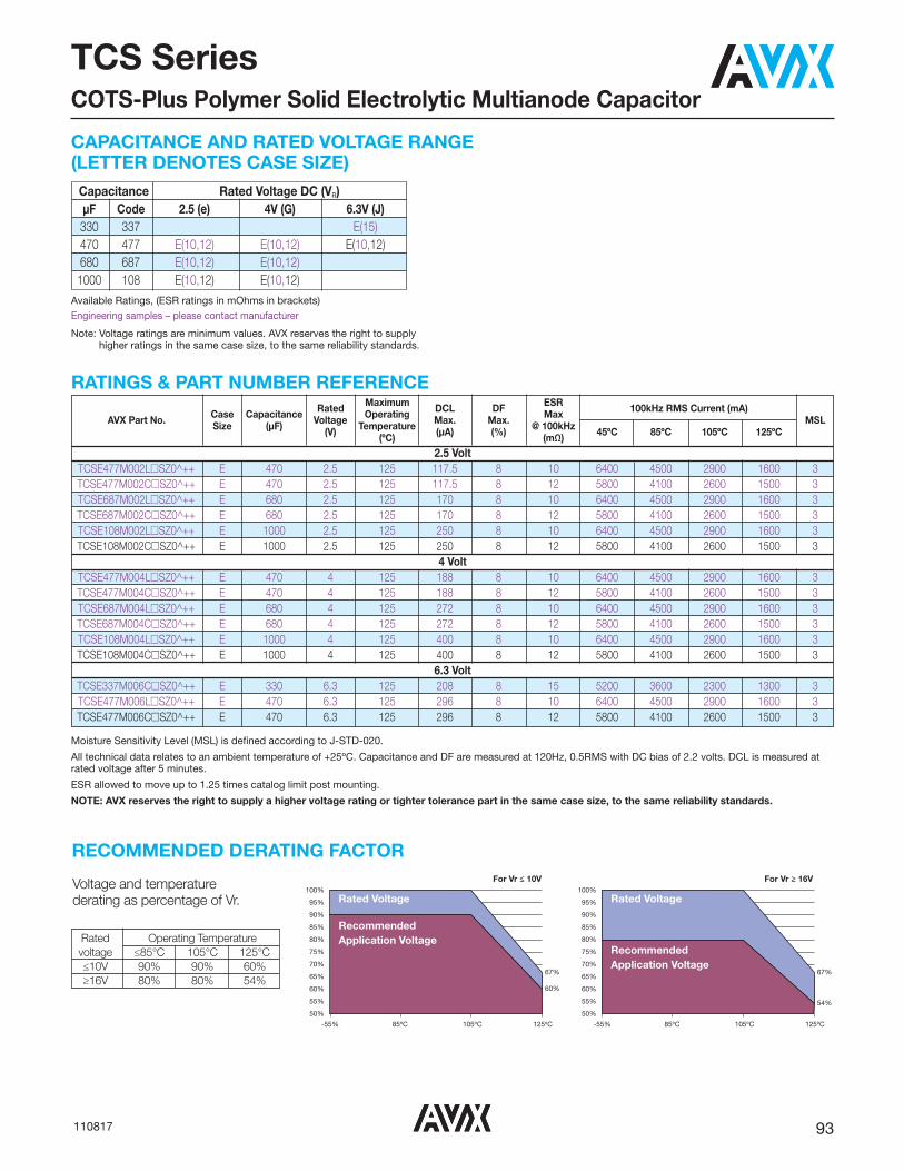
93110817
Capacitance Rated Voltage DC (VR) μF Code 2.5 (e) 4V (G) 6.3V (J) 330 337 E(15) 470 477 E(10,12) E(10,12) E(10,12) 680 687 E(10,12) E(10,12) 1000 108 E(10,12) E(10,12)
CAPACITANCE AND RATED VOLTAGE RANGE(LETTER DENOTES CASE SIZE)
Available Ratings, (ESR ratings in mOhms in brackets)Engineering samples – please contact manufacturer
Note: Voltage ratings are minimum values. AVX reserves the right to supplyhigher ratings in the same case size, to the same reliability standards.
RATINGS & PART NUMBER REFERENCE
Moisture Sensitivity Level (MSL) is defined according to J-STD-020.
All technical data relates to an ambient temperature of +25ºC. Capacitance and DF are measured at 120Hz, 0.5RMS with DC bias of 2.2 volts. DCL is measured atrated voltage after 5 minutes.
ESR allowed to move up to 1.25 times catalog limit post mounting.
NOTE: AVX reserves the right to supply a higher voltage rating or tighter tolerance part in the same case size, to the same reliability standards.
Rated Maximum DCL DF ESR 100kHz RMS Current (mA) AVX Part No. Case Capacitance Voltage Operating Max. Max. Max MSL Size (μF) (V) Temperature (μA) (%) @ 100kHz 45ºC 85ºC 105ºC 125ºC (ºC) (mΩ)
2.5 Volt TCSE477M002L�SZ0^++ E 470 2.5 125 117.5 8 10 6400 4500 2900 1600 3 TCSE477M002C�SZ0^++ E 470 2.5 125 117.5 8 12 5800 4100 2600 1500 3 TCSE687M002L�SZ0^++ E 680 2.5 125 170 8 10 6400 4500 2900 1600 3 TCSE687M002C�SZ0^++ E 680 2.5 125 170 8 12 5800 4100 2600 1500 3 TCSE108M002L�SZ0^++ E 1000 2.5 125 250 8 10 6400 4500 2900 1600 3 TCSE108M002C�SZ0^++ E 1000 2.5 125 250 8 12 5800 4100 2600 1500 3
4 Volt TCSE477M004L�SZ0^++ E 470 4 125 188 8 10 6400 4500 2900 1600 3 TCSE477M004C�SZ0^++ E 470 4 125 188 8 12 5800 4100 2600 1500 3 TCSE687M004L�SZ0^++ E 680 4 125 272 8 10 6400 4500 2900 1600 3 TCSE687M004C�SZ0^++ E 680 4 125 272 8 12 5800 4100 2600 1500 3 TCSE108M004L�SZ0^++ E 1000 4 125 400 8 10 6400 4500 2900 1600 3 TCSE108M004C�SZ0^++ E 1000 4 125 400 8 12 5800 4100 2600 1500 3
6.3 Volt TCSE337M006C�SZ0^++ E 330 6.3 125 208 8 15 5200 3600 2300 1300 3 TCSE477M006L�SZ0^++ E 470 6.3 125 296 8 10 6400 4500 2900 1600 3 TCSE477M006C�SZ0^++ E 470 6.3 125 296 8 12 5800 4100 2600 1500 3
TCS SeriesCOTS-Plus Polymer Solid Electrolytic Multianode Capacitor
RECOMMENDED DERATING FACTOR
Voltage and temperature derating as percentage of Vr.
For Vr ≤ 10V For Vr ≥ 16V
Recommended Application Voltage
100%95%90%85%80%75%70%65%60%55%50%
-55% 85ºC 105ºC 125ºC
67%
60%
Recommended Application Voltage
Rated VoltageRated Voltage100%
95%90%85%80%75%70%65%60%55%50%
-55% 85ºC 105ºC 125ºC
67%
54%
Rated Operating Temperaturevoltage ≤85°C 105°C 125°C≤10V 90% 90% 60%≥16V 80% 80% 54%
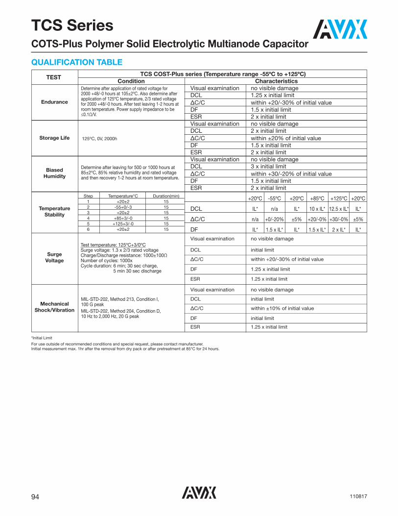
94 110817
TCS SeriesCOTS-Plus Polymer Solid Electrolytic Multianode Capacitor
TEST TCS COST-Plus series (Temperature range -55ºC to +125ºC)Condition Characteristics
Visual examination no visible damageDCL 1.25 x initial limitΔC/C within +20/-30% of initial valueDF 1.5 x initial limitESR 2 x initial limitVisual examination no visible damageDCL 2 x initial limit
125ºC, 0V, 2000h ΔC/C within ±20% of initial valueDF 1.5 x initial limitESR 2 x initial limitVisual examination no visible damageDCL 3 x initial limitΔC/C within +30/-20% of initial valueDF 1.5 x initial limitESR 2 x initial limit
+20ºC -55ºC +20ºC +85ºC +125ºC +20ºC
DCL IL* n/a IL* 10 x IL* 12.5 x IL* IL*
ΔC/C n/a +0/-20% ±5% +20/-0% +30/-0% ±5%
DF IL* 1.5 x IL* IL* 1.5 x IL* 2 x IL* IL*
Visual examination no visible damage
DCL initial limit
ΔC/C within +20/-30% of initial value
DF 1.25 x initial limit
ESR 1.25 x initial limit
Visual examination no visible damage
DCL initial limit
ΔC/C within ±10% of initial value
DF initial limit
ESR 1.25 x initial limit
Determine after application of rated voltage for 2000 +48/-0 hours at 105±2ºC. Also determine afterapplication of 125ºC temperature, 2/3 rated voltagefor 2000 +48/-0 hours. After test leaving 1-2 hours atroom temperature. Power supply impedance to be≤0.1Ω/V.
Determine after leaving for 500 or 1000 hours at85±2ºC, 85% relative humidity and rated voltageand then recovery 1-2 hours at room temperature.
MIL-STD-202, Method 213, Condition I, 100 G peakMIL-STD-202, Method 204, Condition D, 10 Hz to 2,000 Hz, 20 G peak
Test temperature: 125ºC+3/0ºCSurge voltage: 1.3 x 2/3 rated voltageCharge/Discharge resistance: 1000±100ΩNumber of cycles: 1000x Cycle duration: 6 min; 30 sec charge,
5 min 30 sec discharge
Step Temperature°C Duration(min)1 +20±2 152 -55+0/-3 153 +20±2 154 +85+3/-0 155 +125+3/-0 156 +20±2 15
*Initial Limit
For use outside of recommended conditions and special request, please contact manufacturer.Initial measurement max. 1hr after the removal from dry pack or after pretreatment at 85°C for 24 hours.
QUALIFICATION TABLE
MechanicalShock/Vibration
SurgeVoltage
TemperatureStability
BiasedHumidity
Storage Life
Endurance

95100516
DSCC 93026Wet Electrolytic Tantalum Capacitor
Terminal weldedto case (T)
Case
+-
F 6.35 (0.250)W 0.64 +0.05 (.025 +.002)T 2.380 (.094)
F D
E WLE
DSCC AVX L D D E Case Case +0.79 (0.031) Without Insulating With Insulatiing ±6.35 (0.250) Size Size -0.41 (0.016) Sleeve Sleeve ±0.41 (0.016) Max T1 A 11.51 (0.453) 4.78 (0.188) 5.56 (0.219) 38.10 (1.500) T2 B 16.28 (0.641) 7.14 (0.281) 7.92 (0.312) 57.15 (2.250) T3 D 19.46 (0.766) 9.52 (0.375) 10.31 (0.406) 57.15 (2.250) T4 E 26.97 (1.062) 9.52 (0.375) 10.31 (0.406) 57.15 (2.250)
The DSCC 93026 series is an axial leaded wet electrolytic tantalum capacitorand represents a new level of high CV (capacitance/voltage) previouslyunavailable in this technology. These components incorporate a novel, veryhigh capacitance cathode system that allows for higher CV designs, wellbeyond values specified in the MIL-PRF-39006 drawing.This design includes a welded tantalum can and header assembly thatprovides a hermetic seal to withstand harsh shock and vibration requirementsof 39006. Wet tantalums do not require the same derating as solid tantalums.AVX recommends derating components by only 20% in order to enhancereliability.
CASE DIMENSIONS: millimeters (inches)
OUTLINE DIMENSIONS
Voltage (DC) Rated Voltage: (Ur) 85ºC 25 30 50 60 75 100 125 Derated Voltage: (Uc) 125ºC 15 20 30 40 50 65 85 Surge Voltage: (Us) 85ºC 28.8 34.5 57.5 69 86.3 115 144
VOLTAGE RATINGS (Operating Temperature -55ºC to 125ºC)

96 100516
DSCC 93026Wet Electrolytic Tantalum Capacitor
Frequency of Applied 120Hz 800Hz 1kHz Ripple Current Ambient Still Air
≤55 85 105 125 ≤55 85 105 125 ≤55 85 105 125 Temperature (ºC) % of 100% 0.60 0.39 – – 0.71 0.43 – – 0.72 0.45 – – 85ºC 90% 0.60 0.46 – – 0.71 0.55 – _ 0.72 0.55 – – Rated 80% 0.60 0.52 0.35 – 0.71 0.62 0.42 – 0.72 0.62 0.42 – Peak 70% 0.60 0.58 0.44 – 0.71 0.69 0.52 – 0.72 0.70 0.52 – Voltage 66-2/3% 0.60 0.60 0.46 0.27 0.71 0.71 0.55 0.32 0.72 0.72 0.55 0.32
Frequency of Applied 10kHz 40kHz 100kHz Ripple Current Ambient Still Air
≤55 85 105 125 ≤55 85 105 125 ≤55 85 105 125 Temperature (ºC) % of 100% 0.88 0.55 – – 1.00 0.63 – – 1.10 0.69 – – 85ºC 90% 0.88 0.67 – – 1.00 0.77 – _ 1.10 0.85 – – Rated 80% 0.88 0.76 0.52 – 1.00 0.87 0.59 – 1.10 0.96 0.65 – Peak 70% 0.88 0.85 0.64 – 1.00 0.97 0.73 – 1.10 1.07 0.80 – Voltage 66-2/3% 0.88 0.88 0.68 0.40 1.00 1.00 0.77 0.45 1.10 1.10 0.85 0.50
1/ At 125ºC the rated voltage of the capacitors decreases to 66 2/3 of the 85ºC rated voltage.2/ The peak of the applied ac ripple voltage plus the applied dc voltage must not exceed the dc voltage rating of the capacitors.
HOW TO ORDER DSCC 93026 PART NUMBER:
RIPPLE CURRENT MULTIPLIERS vs. Frequency, temperature and applied voltage1/ 2/
�
Insulation SleeveU = Without SleeveS = With Sleeve
93026
DrawingNumber
-XX
DashNumber
See RatingTables
*
CapacitanceTolerance
K = ±10%M = ±20%
Not RoHS Compliant

97100516
DSCC 93026Wet Electrolytic Tantalum Capacitor
RATINGS & PART NUMBER REFERENCE DSCC Cap (μF) DC Rated ESR max DC Leakage max (μA) Impedance Maximum Capacitance AC Ripple Case Size Part 25ºC Voltage (V) (ohms)
+25ºC +85ºC max (Ohms) Change (%) (mA rms)
AVX DSCC Number at 120Hz at 85ºC at 120Hz & +125ºC -55ºC at 120Hz -55ºC +85ºC +125ºC 85ºC at 40kHz
25 VDC at 85ºC 15 VDC at 125ºC 93026- 29*� 120 25 1.3 1 5 25 -42 8 12 1250 A T1 93026- 30*� 560 25 0.83 2 10 12 -65 10 15 2100 B T2 93026- 31*� 1200 25 0.65 5 20 7 -70 12 18 2600 D T3 93026- 32*� 1800 25 0.5 6 25 7 -75 12 20 3100 E T4 93026- 64*� 2200 25 0.5 10 80 10 -90 30 50 3200 E T4
30 VDC at 85ºC 20 VDC at 125ºC 93026- 33*� 100 30 1.3 1 5 25 -38 8 12 1200 A T1 93026- 34*� 470 30 0.85 2 10 15 -65 10 18 1800 B T2 93026- 35*� 1000 30 0.7 7 25 7 -70 10 18 2500 D T3 93026- 36*� 1500 30 0.6 12 35 6 -72 10 20 3000 E T4
50 VDC at 85ºC 30 VDC at 125ºC 93026- 37*� 68 50 1.5 1 5 35 -25 8 15 1050 A T1 93026- 38*� 220 50 0.9 2 10 17.5 -50 8 15 1800 B T2 93026- 39*� 470 50 0.75 3 25 10 -50 8 15 2100 D T3 93026- 40*� 680 50 0.7 5 40 8 -58 10 20 2750 E T4
60 VDC at 85ºC 40 VDC at 125ºC 93026- 41*� 47 60 2 1 5 44 -25 8 12 1050 A T1 93026- 42*� 150 60 1.1 2 10 20 -40 8 15 1650 B T2 93026- 43*� 390 60 0.9 3 25 15 -60 8 15 2100 D T3 93026- 44*� 560 60 0.8 5 40 10 -58 8 15 2750 E T4 93026- 65*� 1000 60 1 12 90 20 -90 30 50 3200 E T4
75 VDC at 85ºC 50 VDC at 125ºC 93026- 45*� 33 75 2.5 1 5 66 -25 5 9 1050 A T1 93026- 46*� 110 75 1.3 2 10 24 -35 6 10 1650 B T2 93026- 47*� 330 75 1 3 30 12 -45 6 10 2100 D T3 93026- 48*� 470 75 0.9 5 50 12 -55 6 10 2750 E T4
100 VDC at 85ºC 65 VDC at 125ºC 93026- 49*� 15 100 3.5 1 5 125 -18 3 10 1050 A T1 93026- 50*� 68 100 2.1 2 10 37 -30 4 12 1650 B T2 93026- 51*� 150 100 1.6 3 25 22 -35 6 12 2100 D T3 93026- 52*� 220 100 1.2 5 50 15 -40 6 12 2750 E T4
125 VDC at 85ºC 85 VDC at 125ºC +93026- 53*� 10 125 5.5 1 5 175 -15 3 10 1050 A T1 +93026- 54*� 47 125 2.3 2 10 47 -25 5 12 1650 B T2 93026- 55*� 100 125 1.8 3 25 35 -35 5 12 2100 D T3 93026- 56*� 150 125 1.6 5 50 20 -35 6 12 2750 E T4
+ Contact factory of leadtime and availability
All technical data relates to an ambient temperature of +25ºC. Capacitance and DF are measured at 120Hz, 0.5RMS with DC bias of 2.2V. DCL is measured at rated voltage after 5 minutes.
NOTE: AVX reserves the rights to supply higher voltage rating in the same case size, to the same reliability standards.

98 102717
TWA SeriesCOTS-Plus Wet Electrolytic Tantalum Capacitor
Terminal weldedto case (T)
Case
+-
F 6.35 (0.250)W 0.64 +0.05 (.025 +.002)T 2.380 (.094)
F D
E WLE
DSCC AVX L D D Case Case +0.79 (0.031) Without Insulating With Insulatiing E Size Size -0.41 (0.016) Sleeve Sleeve ±6.35 (0.250) ±0.41 (0.016) Max T1 A 11.51 (0.453) 4.78 (0.188) 5.56 (0.219) 38.10 (1.500) T2 B 16.28 (0.641) 7.14 (0.281) 7.92 (0.312) 57.15 (2.250) T3 D 19.46 (0.766) 9.52 (0.375) 10.31 (0.406) 57.15 (2.250) T4 E 26.97 (1.062) 9.52 (0.375) 10.31 (0.406) 57.15 (2.250)
The TWA series is an axial leaded wet electrolytic tantalum capacitor with aunique cathode system that promotes very high CV (Capacitance/Voltage)per cc in traditional MIL-PRF-39006 case sizes.The series also utilizes a welded tantalum can and header assembly toprovide a hermetic seal and subsequent long operating lifetime.The construction is similar to DSCC 93026 with capability of meeting harshshock and vibration conditions.
CASE DIMENSIONS: millimeters (inches)
OUTLINE DIMENSIONS
Voltage (DC) Rated Voltage: (VR) 85ºC 15 25 30 50 60 75 100 125 Derated Voltage: (VC) 125ºC 10 15 20 30 40 50 65 85 Surge Voltage: (VS) 85ºC 17.3 28.8 34.5 57.5 69 86.3 115 144
VOLTAGE RATINGS (Operating Temperature -55ºC to 125ºC)

99102717
^
TerminationFinish
0 = Sn/Pb 60/407 = Matte tin
TWA SeriesCOTS-Plus Wet Electrolytic Tantalum Capacitor
*
CapacitanceTolerance
K = ±10%M = ±20%
B
PackagingB = Tray Pack
TWA
Type
E
CaseSize
�
Insulation SleeveC = Without SleeveS = With Sleeve
S
Qualification E = Extended range S = COTS+ L = Group A
Z
ReliabilityZ = Non-ER
0
QualificationLevel
0 = N/A
HOW TO ORDERAVX PART NUMBER:
100
VoltageCode
407
CapacitanceCode
pF code: 1st two digits
representsignificant figures 3rd
digit representsmultiplier
(number ofzeros to follow)
00
Custom TestOptions
00 = Standard01 = Random
vibration*
Frequency of Applied 120Hz 800Hz 1kHz Ripple Current Ambient Still Air
≤55 85 105 125 ≤55 85 105 125 ≤55 85 105 125 Temperature (ºC) % of 100% 0.60 0.39 – – 0.71 0.43 – – 0.72 0.45 – – 85ºC 90% 0.60 0.46 – – 0.71 0.55 – _ 0.72 0.55 – – Rated 80% 0.60 0.52 0.35 – 0.71 0.62 0.42 – 0.72 0.62 0.42 – Peak 70% 0.60 0.58 0.44 – 0.71 0.69 0.52 – 0.72 0.70 0.52 – Voltage 66-2/3% 0.60 0.60 0.46 0.27 0.71 0.71 0.55 0.32 0.72 0.72 0.55 0.32
Frequency of Applied 10kHz 40kHz 100kHz Ripple Current Ambient Still Air
≤55 85 105 125 ≤55 85 105 125 ≤55 85 105 125 Temperature (ºC) % of 100% 0.88 0.55 – – 1.00 0.63 – – 1.10 0.69 – – 85ºC 90% 0.88 0.67 – – 1.00 0.77 – _ 1.10 0.85 – – Rated 80% 0.88 0.76 0.52 – 1.00 0.87 0.59 – 1.10 0.96 0.65 – Peak 70% 0.88 0.85 0.64 – 1.00 0.97 0.73 – 1.10 1.07 0.80 – Voltage 66-2/3% 0.88 0.88 0.68 0.40 1.00 1.00 0.77 0.45 1.10 1.10 0.85 0.50
1/ At 125ºC the rated voltage of the capacitors decreases to 66 2/3 of the 85ºC rated voltage.2/ The peak of the applied ac ripple voltage plus the applied dc voltage must not exceed the dc voltage rating of the capacitors.
RIPPLE CURRENT MULTIPLIERS vs. Frequency, temperature and applied voltage1/ 2/
LEAD-FREE COMPATIBLECOMPONENT
For RoHS compliant products, please select correct termination style.
* Please contact the factory for additional details and availability.

100 102717
TWA SeriesCOTS-Plus Wet Electrolytic Tantalum Capacitor
Capacitance Rated Voltage DC (VR) to 85°C μF Code 15V 25V 30V 50V 60V 75V 100V 125V 10 106 A(M) A 15 156 A 22 226 B 27 276 B 33 336 A 47 476 B A B 68 686 A A A(M) B 82 826 E 100 107 A A(M) B B D 110 117 B 120 127 A B D 150 157 B B D E 220 227 B B E D,E E 270 277 B 330 337 B E D,E E 390 397 D D 400 407 E 470 477 B D,E E E 560 567 B E E 660 667 E 680 687 E D,E E E E 750 757 D,E D,E E E E E 1000 108 D,E D,E D,E E E 1200 128 D E 1500 158 E E E 1800 188 E 2200 228 E E(M)
3000 308 E(M)
4700 478 E
CAPACITANCE AND RATED VOLTAGE, VR (VOLTAGE CODE) RANGE (LETTER DENOTES CASE SIZE)
Available Ratings (M tolerance only)
Engineering samples - please contact manufacturer

101102717
TWA SeriesCOTS-Plus Wet Electrolytic Tantalum Capacitor
RATINGS & PART NUMBER REFERENCE Cap (μF) DC Rated ESR Max DC Leakage max (μA) Impedance Maximum Capacitance Change AC Ripple Case Size AVX Part Number 25ºC Voltage (V) (Ohms) +25ºC +85 & max (Ohms) (%) (mA rms) at 120Hz at 85ºC at 120Hz +125ºC -55ºC at 120Hz -55ºC +85ºC +125ºC 85ºC at 40kHZ AVX DSCC
15 VDC at 85°C 10 VDC at 125°C TWAD397*015�BSZ0^00 390 15 1.7 7 28 48 -70 25 25 1396 D T3
25 VDC at 85°C 15 VDC at 125°C TWAA686*025�BEZ0^00 68 25 2.5 0.6 3 45 -40 12 15 850 A T1 TWAA127*025�BSZ0000 120 25 1.3 1 5 25 -42 8 12 1250 A T1 TWAA127*025�BEZ0^00* 120 25 2.3 2 10 35 -42 20 25 1250 A T1 TWAB277*025�BEZ0^00 270 25 0.9 4 20 17.5 -50 18 28 1800 B T2 TWAB337*025�BEZ0^00 330 25 1.3 2 20 25 -60 10 15 1550 B T2 TWAB567*025�BSZ0^00 560 25 0.83 2 10 12 -65 10 15 2100 B T2 TWAE687*025�BEZ0^00 680 25 0.75 3 12 12 -50 8 15 2100 E T4 TWAD757*025�BEZ0^00 750 25 1 3 25 15 -50 8 15 2000 D T3 TWAE757*025�BEZ0^00 750 25 0.75 3.5 16 9 -55 10 18 2200 E T4 TWAD108*025�BEZ0^00 1000 25 1 4 30 15 -50 8 15 2300 D T3 TWAE108*025�BEZ0^00 1000 25 0.7 4 20 9 -55 10 18 2400 E T4 TWAD128*025�BSZ0^00 1200 25 0.65 5 20 7 -70 12 18 2600 D T3 TWAD128*025�BEZ0^00* 1200 25 0.65 5 20 7 -70 12 18 2600 D T3 TWAE158*025�BEZ0^00 1500 25 0.5 6 24 7 -65 15 20 2850 E T4 TWAE188*025�BSZ0^00 1800 25 0.5 6 25 7 -75 12 20 3100 E T4 TWAE228*025�BSZ0^00 2200 25 0.5 10 80 10 -90 30 50 3200 E T4 TWAE478*025�BSZ0^00 4700 25 0.5 30 180 5 -90 60 80 4250 E T4 TWAE478*025�BEZ0^00* 4700 25 0.5 30 180 5 -90 60 80 4250 E T4
30 VDC at 85°C 20 VDC at 125°C TWAA107*030�BSZ0000 100 30 1.3 1 5 25 -38 8 12 1200 A T1 TWAA107*030�BEZ0^00* 100 30 2.3 2 10 35 -38 20 25 1200 A T1 TWAB227*030�BEZ0^00 220 30 2 1.9 10 40 -40 18 28 1200 B T2 TWAB477*030�BSZ0^00 470 30 0.85 2 10 15 -65 10 18 1800 B T2 TWAD687*030�BEZ0^00 680 30 1 3.3 25 15 -50 8 15 1900 D T3 TWAE687*030�BEZ0^00 680 30 0.8 4.5 18 10 -60 8 15 2100 E T4 TWAD757*030�BEZ0^00 750 30 1 3.6 30 15 -50 8 15 2000 D T3 TWAE757*030�BEZ0^00 750 30 0.8 5 20 10 -65 10 18 2200 E T4 TWAD108*030�BSZ0^00 1000 30 0.7 7 25 7 -70 10 18 2500 D T3 TWAD108*030�BEZ0^00* 1000 30 0.7 7 25 7 -70 10 18 2500 D T3 TWAE108*030�BEZ0^00 1000 30 0.7 5 20 7 -70 10 18 2500 E T4 TWAE158*030�BSZ0^00 1500 30 0.6 12 35 6 -72 10 20 3000 E T4
50 VDC at 85°C 30 VDC at 125°C TWAB476*050�BSZ0^00 47 50 3 0.8 8 70 -28 13 15 1155 B T2 TWAA686*050�BSZ0000 68 50 1.5 1 5 35 -25 8 15 1050 A T1 TWAA686*050�BEZ0^00* 68 50 2.5 2 10 45 -25 20 25 1050 A T1 TWAA107M050�BSZ0^00 100 50 5 2 15 70 -45 50 95 1500 A T1 TWAB127*050�BEZ0^00 120 50 2 2 10 40 -45 8 15 1200 B T2 TWAB157*050�BEZ0^00 150 50 2 2 10 25 -50 8 15 1400 B T2 TWAB227*050�BSZ0000 220 50 0.9 2 10 17.5 -50 8 15 1800 B T2 TWAB227*050�BEZ0^00* 220 50 0.9 4 20 17.5 -50 18 28 1800 B T2 TWAE337*050�BSZ0^00 330 50 0.8 2.5 25 15 -50 8 15 1900 E T4 TWAE337*050�BEZ0^00* 330 50 0.8 2.5 25 15 -50 8 15 1900 E T4 TWAD477*050�BSZ0^00 470 50 0.75 3 25 10 -50 8 15 2100 D T3 TWAD477*050�BEZ0^00* 470 50 1 3 25 11 -50 8 15 2100 D T3 TWAE477*050�BSZ0^00 470 50 0.75 3 30 10 -50 8 15 2200 E T4 TWAE477*050�BEZ0^00* 470 50 0.75 3 30 10 -50 8 15 2200 E T4 TWAE687*050�BSZ0^00 680 50 0.7 5 40 8 -58 10 20 2750 E T4 TWAE687*050�BEZ0^00* 680 50 0.7 5 40 8 -58 10 20 2750 E T4 TWAE757*050�BEZ0^00 750 50 0.6 12 60 8 -50 15 20 2800 E T4 TWAD108*050�BEZ0^00 1000 50 1.5 20 125 12 -90 100 140 2500 D T3 TWAE108*050�BSZ0^00 1000 50 1.0 12 90 20 -90 30 50 3200 E T4 TWAE108*050�BEZ0^00* 1000 50 0.7 11 110 20 -70 30 40 3200 E T4 TWAE128*050�BSZ0^00 1200 50 1.0 12 90 20 -90 30 50 3200 E T4 TWAE158*050�BSZ0^00 1500 50 1 35 130 6 -75 45 55 3500 E T4 TWAE308M050�BSZ0^00 3000 50 0.3 30 150 3.5 -80 60 85 3100 E T4TWAE308M050�BEZ0^00* 3000 50 0.3 30 150 3.5 -80 60 85 3100 E T4
60 VDC at 85°C 40 VDC at 125°C TWAA476*060�BSZ0000 47 60 2 1 5 44 -25 8 12 1050 A T1 TWAA476*060�BEZ0^00* 47 60 2 2 10 55 -25 15 25 1050 A T1 TWAB107*060�BEZ0^00 100 60 2.5 1.7 10 40 -40 8 15 1100 B T2 TWAB157*060�BSZ0000 150 60 1.1 2 10 20 -40 8 15 1650 B T2 TWAB157*060�BEZ0^00* 150 60 1.5 2 10 30 -35 12 20 1650 B T2 TWAD397*060�BSZ0^00 390 60 0.9 3 25 15 -60 8 15 2100 D T3

102 102717
TWA SeriesCOTS-Plus Wet Electrolytic Tantalum Capacitor
All technical data relates to an ambient temperature of +25ºC. Capacitance and DF are measured at 120Hz, 0.5RMSwith DC bias of 2.2V. DCL is measured at rated voltage after 5 minutes.NOTE: AVX reserves the rights to supply higher voltage rating in the same case size, to the same reliability standards.*Not recommended for new designs, for new design use part number with Inspection level “S” – COTS-Plus
RATINGS & PART NUMBER REFERENCE Cap (μF) DC Rated ESR Max DC Leakage max (μA) Impedance Maximum Capacitance Change AC Ripple Case Size AVX Part Number 25ºC Voltage (V) (Ohms) +25ºC +85 & max (Ohms) (%) (mA rms) at 120Hz at 85ºC at 120Hz +125ºC -55ºC at 120Hz -55ºC +85ºC +125ºC 85ºC at 40kHZ AVX DSCC TWAD397*060�BEZ0^00* 390 60 0.9 3 25 15 -60 8 15 2100 D T3 TWAE567*060�BSZ0^00 560 60 0.8 5 40 10 -58 8 15 2750 E T4 TWAE567*060�BEZ0^00* 560 60 0.8 5 40 10 -58 8 15 2750 E T4 TWAE687*060�BEZ0^00 680 60 0.6 13 65 8 -50 15 20 2800 E T4 TWAE757*060�BEZ0^00 750 60 0.6 15 75 8 -50 15 20 2800 E T4 TWAE108*060�BSZ0^00 1000 60 1 12 90 20 -90 30 50 3200 E T4 TWAE108*060�BEZ0^00* 1000 60 0.5 20 60 4.5 -70 30 60 3200 E T4 TWAE228M060�BEZ0^00 2200 60 0.5 40 120 3.0 -80 60 80 3000 E T4
75 VDC at 85°C 50 VDC at 125°C TWAA336*075�BSZ0000 33 75 2.5 1 5 66 -25 5 9 1050 A T1 TWAA336*075�BEZ0^00* 33 75 2.5 2 10 70 -25 15 25 1050 A T1 TWAA686M075�BSZ0^00 68 75 5 2 15 70 -45 50 95 1500 A T1 TWAB107*075�BEZ0^00 100 75 2.5 2 10 40 -35 6 10 1400 B T2 TWAB117*075�BSZ0000 110 75 1.3 2 10 24 -35 6 10 1650 B T2 TWAB117*075�BEZ0^00* 110 75 1.5 2 10 30 -35 12 20 1650 B T2 TWAE227*075�BSZ0^00 220 75 1.1 2.5 30 20 -50 6 10 1800 E T4 TWAE227*075�BEZ0^00* 220 75 1.1 2.5 30 20 -50 6 10 1800 E T4 TWAD337*075�BSZ0^00 330 75 1 3 30 12 -45 6 10 2100 D T3 TWAD337*075�BEZ0^00* 330 75 1.2 3 30 15 -60 10 20 2100 D T3 TWAE337*075�BEZ0^00 330 75 1 3 40 12 -50 6 10 2200 E T4 TWAE477*075�BSZ0^00 470 75 0.9 5 50 12 -55 6 10 2750 E T4 TWAE477*075�BEZ0^00* 470 75 0.9 5 50 12 -55 6 10 2750 E T4 TWAE667*075�BSZ0^00 660 75 0.7 12 120 10 -70 30 40 2750 E T4 TWAE687*075�BEZ0^00 680 75 0.9 11 110 10 -70 30 40 2750 E T4 TWAE757*075�BSZ0^00 750 75 0.7 12 120 10 -70 30 40 3800 E T4 TWAE757*075�BEZ0^00* 750 75 0.7 12 120 10 -70 30 40 3800 E T4 TWAE108*075�BEZ0^00 1000 75 0.5 30 90 4.5 -70 30 60 3500 E T4
100 VDC at 85°C 65 VDC at 125°C TWAA106M100�BSZ0^00 10 100 3.5 5 25 190 -18 10 30 1050 A T1 TWAA156*100�BSZ0000 15 100 3.5 1 5 125 -18 3 10 1050 A T1 TWAA156*100�BEZ0^00* 15 100 5.5 7 35 140 -18 10 30 1050 A T1 TWAB226*100�BSZ0^00 22 100 4 1 5 100 -10 8 15 1065 B T2 TWAB686*100�BSZ0000 68 100 2.1 2 10 37 -30 4 12 1650 B T2 TWAB686*100�BEZ0^00* 68 100 2.5 2 10 37 -30 4 12 1650 B T2 TWAD157*100�BSZ0^00 150 100 1.6 3 25 22 -35 6 12 2100 D T3 TWAD157*100�BEZ0^00* 150 100 1.6 3 25 22 -35 6 12 2100 D T3 TWAD227*100�BEZ0^00 220 100 1.4 5 25 18 -50 10 15 2500 D T3 TWAE227*100�BSZ0^00 220 100 1.2 5 50 15 -40 6 12 2750 E T4 TWAE227*100�BEZ0^00* 220 100 1.2 5 50 15 -40 6 12 2750 E T4 TWAE337*100�BSZ0^00 330 100 0.8 6 60 10 -45 7 20 3600 E T4 TWAE337*100�BEZ0^00* 330 100 0.8 6 60 10 -45 7 20 3600 E T4 TWAE407*100�BSZ0^00 400 100 0.8 10 150 10 -50 10 35 4100 E T4 TWAE407*100�BEZ0^00* 400 100 0.8 10 150 10 -50 10 35 4100 E T4 TWAE477*100�BSZ0^00 470 100 0.7 15 150 10 -50 10 35 4100 E T4 TWAE567*100�BSZ0^00 560 100 1.0 25 200 10 -60 45 110 4100 E T4 TWAE757*100�BEZ0^00 750 100 0.6 30 150 5 -60 50 120 4200 E T4
125 VDC at 85°C 85 VDC at 125°C TWAA106*125�BSZ0000 10 125 5.5 1 5 175 -15 3 10 1050 A T1TWAA106M125�BEZ0^00* 10 125 5.5 1 5 190 -15 10 30 1050 A T1 TWAB276*125�BSZ0^00 27 125 4 2 10 100 -10 8 15 1200 B T2 TWAB476*125�BSZ0000 47 125 2.3 2 10 47 -25 5 12 1650 B T2 TWAB476*125�BEZ0^00* 47 125 2.3 2 10 47 -25 5 12 1650 B T2 TWAE826*125�BSZ0^00 82 125 1.6 2 10 39 -24 10 20 1900 E T4 TWAD107*125�BSZ0^00 100 125 1.8 3 25 35 -35 5 12 2100 D T3 TWAD107*125�BEZ0^00* 100 125 1.8 3 25 35 -35 5 12 2100 D T3 TWAD127*125�BEZ0^00 120 125 1.8 3 25 35 -35 5 12 2100 D T3 TWAE157*125�BSZ0^00 150 125 1.6 5 50 20 -35 6 12 2750 E T4 TWAE157*125�BEZ0^00* 150 125 1.6 5 50 20 -35 6 16 2750 E T4 TWAE227*125�BEZ0^00 220 125 1.4 10 50 12 -40 8 15 3600 E T4
DF = 2πfC x (ESR)2π = 6.28f = 120HzC = Actual measured capacitanceESR = Actual measured ESR
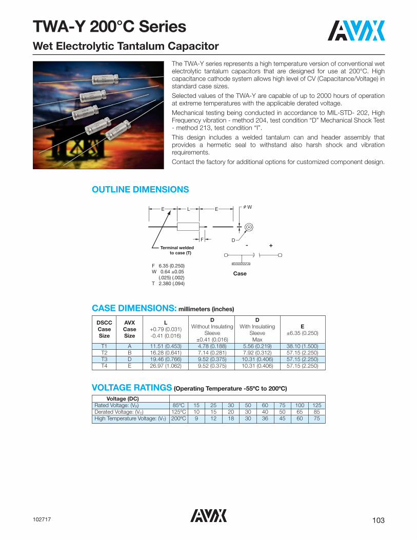
103102717
TWA-Y 200°C SeriesWet Electrolytic Tantalum Capacitor
Terminal weldedto case (T)
Case
+-
F 6.35 (0.250)W 0.64 ±0.05 (.025) (.002)T 2.380 (.094)
F D
E WLE
The TWA-Y series represents a high temperature version of conventional wetelectrolytic tantalum capacitors that are designed for use at 200°C. Highcapacitance cathode system allows high level of CV (Capacitance/Voltage) instandard case sizes.Selected values of the TWA-Y are capable of up to 2000 hours of operationat extreme temperatures with the applicable derated voltage.Mechanical testing being conducted in accordance to MIL-STD- 202, HighFrequency vibration - method 204, test condition “D” Mechanical Shock Test- method 213, test condition “I”.This design includes a welded tantalum can and header assembly thatprovides a hermetic seal to withstand also harsh shock and vibrationrequirements.Contact the factory for additional options for customized component design.
OUTLINE DIMENSIONS
DSCC AVX L D D Case Case +0.79 (0.031) Without Insulating With Insulatiing E Size Size -0.41 (0.016) Sleeve Sleeve ±6.35 (0.250) ±0.41 (0.016) Max T1 A 11.51 (0.453) 4.78 (0.188) 5.56 (0.219) 38.10 (1.500) T2 B 16.28 (0.641) 7.14 (0.281) 7.92 (0.312) 57.15 (2.250) T3 D 19.46 (0.766) 9.52 (0.375) 10.31 (0.406) 57.15 (2.250) T4 E 26.97 (1.062) 9.52 (0.375) 10.31 (0.406) 57.15 (2.250)
CASE DIMENSIONS: millimeters (inches)
Voltage (DC) Rated Voltage: (VR) 85ºC 15 25 30 50 60 75 100 125 Derated Voltage: (VC) 125ºC 10 15 20 30 40 50 65 85 High Temperature Voltage: (VT) 200ºC 9 12 18 30 36 45 60 75
VOLTAGE RATINGS (Operating Temperature -55ºC to 200ºC)

104 102717
TWA-Y 200°C SeriesWet Electrolytic Tantalum Capacitor
^
TerminationFinish
0 = Sn/Pb 60/407 = Matte tin
*
CapacitanceTolerance
K = ±10%M = ±20%
B
PackagingB = Tray Pack
TWA
Type
E
CaseSize
�
Insulation SleeveC = Without SleeveS = With Sleeve
Y
QualificationY = High Temp
Z
ReliabilityZ = Non-ER
0
QualificationLevel
0 = N/A
HOW TO ORDERAVX PART NUMBER:
075
VoltageCode
757
CapacitanceCode
pF code: 1st two digits
representsignificant figures 3rd
digit representsmultiplier
(number ofzeros to follow)
00
Custom TestOptions
00 = Standard
Frequency of Applied 120Hz 800Hz 1kHz Ripple Current Ambient Still Air
≤55 85 105 125 ≤55 85 105 125 ≤55 85 105 125 Temperature (ºC) % of 100% 0.60 0.39 – – 0.71 0.43 – – 0.72 0.45 – – 85ºC 90% 0.60 0.46 – – 0.71 0.55 – _ 0.72 0.55 – – Rated 80% 0.60 0.52 0.35 – 0.71 0.62 0.42 – 0.72 0.62 0.42 – Peak 70% 0.60 0.58 0.44 – 0.71 0.69 0.52 – 0.72 0.70 0.52 – Voltage 66-2/3% 0.60 0.60 0.46 0.27 0.71 0.71 0.55 0.32 0.72 0.72 0.55 0.32
Frequency of Applied 10kHz 40kHz 100kHz Ripple Current Ambient Still Air
≤55 85 105 125 ≤55 85 105 125 ≤55 85 105 125 Temperature (ºC) % of 100% 0.88 0.55 – – 1.00 0.63 – – 1.10 0.69 – – 85ºC 90% 0.88 0.67 – – 1.00 0.77 – _ 1.10 0.85 – – Rated 80% 0.88 0.76 0.52 – 1.00 0.87 0.59 – 1.10 0.96 0.65 – Peak 70% 0.88 0.85 0.64 – 1.00 0.97 0.73 – 1.10 1.07 0.80 – Voltage 66-2/3% 0.88 0.88 0.68 0.40 1.00 1.00 0.77 0.45 1.10 1.10 0.85 0.50
1/ At 125ºC the rated voltage of the capacitors decreases to 66 2/3 of the 85ºC rated voltage.2/ The peak of the applied ac ripple voltage plus the applied dc voltage must not exceed the dc voltage rating of the capacitors.
RIPPLE CURRENT MULTIPLIERS vs. Frequency, temperature and applied voltage1/ 2/
LEAD-FREE COMPATIBLECOMPONENT
For RoHS compliant products, please select correct termination style.

105102717
TWA-Y 200°C Series Wet Electrolytic Tantalum Capacitor
Capacitance Rated Voltage DC (VR) to 85°C μF Code 15V 25V 30V 50V 60V 75V 100V 125V 10 106 A A(M) A(M)
15 156 A A 22 226 A A A B 27 276 A B 33 336 A A A 47 476 B A B 50 506 B 56 566 A A B 60 606 B 68 686 A A B A(M) B 82 826 B B D,E 100 107 B A,B A(M) D 110 117 B B 120 127 A,B B 150 157 B B D E 180 187 D 220 227 B B D E E E 270 277 B D E 300 307 D 330 337 E E 390 397 D D 400 407 E 470 477 B,D E E 560 567 B,E E E 680 687 E 750 757 E E 1000 108 D E E E 1200 128 D 1500 158 E 3000 308 E(M)
CAPACITANCE AND RATED VOLTAGE, VR (VOLTAGE CODE) RANGE (LETTER DENOTES CASE SIZE)
Available Ratings (M tolerance only)
Engineering samples - please contact manufacturer
RATINGS & PART NUMBER REFERENCE Cap (μF) DC Rated ESR Max DC Leakage max (μA) Impedance Maximum Capacitance Change AC Ripple Case Size Lifetime at AVX Part Number 25ºC Voltage (V) (Ohms) +25ºC +85 & max (Ohms) (%) (mA rms) 200°C (hrs.) at 120Hz at 85ºC at 120Hz +125ºC -55ºC at 120Hz -55ºC +85ºC +125ºC 85ºC at 40kHZ AVX DSCC
15 VDC at 85°C 10 VDC at 125°C 9 VDC at 200°C TWAA336*015�BYZ0^00 33 15 4 1 2 90 -28 14 16 820 A T1 2000 TWAD397*015�BYZ0^00 390 15 1.7 7 28 48 -70 25 25 1396 D T3 1000
25 VDC at 85°C 15 VDC at 125°C 12 VDC at 200°C TWAA226*025�BYZ0^00 22 25 4 1 2 140 -20 10.5 12 825 A T1 2000 TWAA566*025�BYZ0^00 56 25 4 1 2 140 -20 10.5 12 825 A T1 500 TWAA686*025�BYZ0^00 68 25 4 1 2 140 -20 10.5 12 825 A T1 500 TWAB107*025�BYZ0^00 100 25 2.5 1 10 60 -35 13 15 - B T2 2000 TWAA127*025�BYZ0^00 120 25 2.3 2 10 35 -42 20 25 1250 A T1 500 TWAB127*025�BYZ0^00 120 25 2.3 2 10 60 -32 13 15 - B T2 500 TWAB277*025�BYZ0^00 270 25 0.9 4 20 17.5 -50 18 28 1800 B T2 1000 TWAB567*025�BYZ0^00 560 25 1.0 2 10 12 -65 10 15 2100 B T2 1000 TWAE567*025�BYZ0^00 560 25 1.3 9 36 25 -65 25 30 - E T4 2000 TWAD128*025�BYZ0^00 1200 25 0.65 5 20 7 -70 12 18 2600 D T3 1000 TWAE308M025�BYZ0^00 3000 25 0.5 15 30 3.5 -80 60 85 3100 E T4 500
30 VDC at 85°C 20 VDC at 125°C 18 VDC at 200°C TWAA156*030�BYZ0^00 15 30 4.4 1 2 200 -20 10.5 16 - A T1 2000 TWAA566*030�BYZ0^00 56 30 5.2 2 9 200 -48 12 15 - A T1 2000 TWAA107*030�BYZ0^00 100 30 2.3 2 10 35 -38 20 25 1200 A T1 500 TWAB107*030�BYZ0^00 100 30 2.3 2 12 60 -30 10.5 12 - B T2 500

106 102717
TWA-Y 200°C Series Wet Electrolytic Tantalum Capacitor
RATINGS & PART NUMBER REFERENCE Cap (μF) DC Rated ESR Max DC Leakage max (μA) Impedance Maximum Capacitance Change AC Ripple Case Size Lifetime at AVX Part Number 25ºC Voltage (V) (Ohms) +25ºC +85 & max (Ohms) (%) (mA rms) 200°C (hrs.) at 120Hz at 85ºC at 120Hz +125ºC -55ºC at 120Hz -55ºC +85ºC +125ºC 85ºC at 40kHZ AVX DSCC TWAB157*030�BYZ0^00 150 30 2.5 2 18 40 -48 13 15 1100 B T2 2000 TWAB227*030�BYZ0^00 220 30 0.9 4 20 17.5 -50 18 28 1800 B T2 1000 TWAD307*030�BYZ0^00 300 30 1.8 8 32 25 -51 20 25 - D T3 2000 TWAD397*030�BYZ0^00 390 30 1.8 6 18 25 -65 18 25 - D T3 2000 TWAB477*030�BYZ0^00 470 30 1.0 2 10 15 -65 10 18 1800 B T2 1000 TWAD477*030�BYZ0^00 470 30 1.0 3 25 15 -65 15 25 1600 D T3 2000 TWAE567*030�BYZ0^00 560 30 1.3 9 36 25 -65 25 30 - E T4 2000 TWAD108*030�BYZ0^00 1000 30 0.7 7 25 7 -70 10 18 2500 D T3 1000
50 VDC at 85°C 30 VDC at 125°C 30 VDC at 200°C TWAA106*050�BYZ0^00 10 50 5.3 1 2 250 -24 8 9 715 A T1 2000 TWAA336*050�BYZ0^00 33 50 5 2 9 200 -39 10 12 - A T1 2000 TWAB476*050�BYZ0^00 47 50 3 0.8 8 70 -28 13 15 1155 B T2 500 TWAB606*050�BYZ0^00 60 50 2.6 2 12 60 -30 10.5 12 - B T2 500 TWAA686*050�BYZ0^00 68 50 2.5 2 10 45 -25 20 25 1050 A T1 1000 TWAB826*050�BYZ0^00 82 50 2.4 2 16 60 -32 13 15 - B T2 500 TWAA107M050�BYZ0^00 100 50 5 2 15 70 -45 50 95 1500 A T1 500 TWAB127*050�BYZ0^00 120 50 2.5 4 24 40 -42 12 15 - B T2 2000 TWAB227*050�BYZ0^00 220 50 0.9 4 20 17.5 -50 18 28 1800 B T2 1000 TWAD277*050�BYZ0^00 270 50 1.8 8 32 25 -51 20 25 - D T3 2000 TWAE337*050�BYZ0^00 330 50 1.5 9 36 25 -46 25 30 1900 E T4 2000 TWAE108*050�BYZ0^00 1000 50 0.7 11 110 20 -70 30 40 3200 E T4 500 TWAE158*050�BYZ0^00 1500 50 1 35 130 6 -75 45 55 3500 E T4 1000
60 VDC at 85°C 40 VDC at 125°C 36 VDC at 200°C TWAA226*060�BYZ0^00 22 60 5 3 12 200 -34 10 12 500 A T1 2000 TWAA276*060�BYZ0^00 27 60 5 3 12 200 -34 10 12 - A T1 2000 TWAA476*060�BYZ0^00 47 60 2 2 10 55 -25 15 25 1050 A T1 500 TWAB506*060�BYZ0^00 50 60 2.6 2 12 60 -30 10.5 12 - B T2 500 TWAB686*060�BYZ0^00 68 60 2.5 2 16 60 -32 10.5 12 - B T2 500 TWAB107*060�BYZ0^00 100 60 2.5 1.7 10 40 -40 8 15 1100 B T2 2000 TWAB157*060�BYZ0^00 150 60 1.5 2 10 30 -35 12 20 1650 B T2 500 TWAD227*060�BYZ0^00 220 60 1.8 8 32 25 -45 16 20 - D T3 2000 TWAE277*060�BYZ0^00 270 60 1.3 9 36 25 -45 20 25 - E T4 2000 TWAE108*060�BYZ0^00 1000 60 0.5 20 60 4.5 -70 30 60 3200 E T4 1000
75 VDC at 85°C 50 VDC at 125°C 45 VDC at 200°C TWAA226*075�BYZ0^00 22 75 5.1 3 12 157 -19 10 12 600 A T1 2000 TWAA336*075�BYZ0^00 33 75 2.5 2 10 70 -25 15 25 1050 A T1 1000 TWAB566*075�BYZ0^00 56 75 2.6 2 17 60 -30 10.5 15 - B T2 500 TWAA686M075�BYZ0^00 68 75 5 2 15 70 -45 50 95 1500 A T1 500 TWAB826*075�BYZ0^00 82 75 2.5 4 24 37 -30 12 15 - B T2 500 TWAB117*075�BYZ0^00 110 75 1.5 2 10 30 -35 12 20 1650 B T2 500 TWAD187*075�BYZ0^00 180 75 2.2 9 36 25 -40 16 20 - D T3 2000 TWAE227*075�BYZ0^00 220 75 1.2 5 50 20 -40 8 15 1800 E T4 2000 TWAE477*075�BYZ0^00 470 75 0.9 10 125 10 -50 10 35 2750 E T4 1000 TWAE687*075�BYZ0^00 680 75 0.9 11 110 10 -70 30 40 2750 E T4 500 TWAE757*075�BYZ0^00 750 75 0.7 12 120 10 -70 30 40 3800 E T4 500 TWAE108*075�BYZ0^00 1000 75 0.5 30 90 4.5 -70 30 60 3500 E T4 1000
100 VDC at 85°C 65 VDC at 125°C 60 VDC at 200°C TWAA106M100�BYZ0^00 10 100 3.5 5 25 190 -18 10 30 1050 A T1 2000 TWAA156*100�BYZ0^00 15 100 5.5 7 35 140 -18 10 30 1050 A T1 500 TWAB226*100�BYZ0^00 22 100 4 1 5 100 -10 8 15 1065 B T2 500 TWAB686*100�BYZ0^00 68 100 2.5 2 10 37 -30 4 12 1650 B T2 500 TWAD157*100�BYZ0^00 150 100 1.6 3 25 22 -35 6 12 2100 D T3 2000 TWAE227*100�BYZ0^00 220 100 1.2 5 50 15 -40 6 12 2750 E T4 2000 TWAE337*100�BYZ0^00 330 100 0.8 6 60 10 -45 7 20 3600 E T4 2000 TWAE407*100�BYZ0^00 400 100 0.8 10 150 10 -50 10 35 4100 E T4 2000 TWAE477*100�BYZ0^00 470 100 0.7 15 150 10 -50 10 35 4100 E T4 2000 TWAE567*100�BYZ0^00 560 100 1.0 25 200 10 -60 45 110 4100 E T4 1500 TWAE757*100�BYZ0^00 750 100 0.6 30 150 5 -60 50 120 4200 E T4 500
125 VDC at 85°C 85 VDC at 125°C 75 VDC at 200°C TWAA106M125�BYZ0^00 10 125 5.5 1 5 190 -15 10 30 1050 A T1 2000 TWAB276*125�BYZ0^00 27 125 4 2 10 100 -10 8 15 1200 B T2 500 TWAB476*125�BYZ0^00 47 125 2.3 2 10 47 -25 5 12 1650 B T2 1000 TWAD826*125�BYZ0^00 82 125 2.8 12 48 50 -30 15 17 - D T3 2000 TWAE826*125�BYZ0^00 82 125 1.6 2 10 39 -24 10 20 1900 E T4 2000 TWAD107*125�BYZ0^00 100 125 1.8 3 25 35 -35 5 12 2100 D T3 2000 TWAE157*125�BYZ0^00 150 125 1.6 5 50 20 -35 6 16 2750 E T4 2000 TWAE227*125�BYZ0^00 220 125 1.4 10 50 12 -40 8 15 3600 E T4 2000
All technical data relates to an ambient temperature of +25ºC. Capacitance and DF are measured at 120Hz, 0.5RMSwith DC bias of 2.2V. DCL is measured at rated voltage after 5 minutes.NOTE: AVX reserves the rights to supply higher voltage rating in the same case size, to the same reliability standards.*Not recommended for new designs, for new design use part number with Inspection level “S” – COTS-Plus
DF = 2πfC x (ESR)2π = 6.28f = 120HzC = Actual measured capacitanceESR = Actual measured ESR
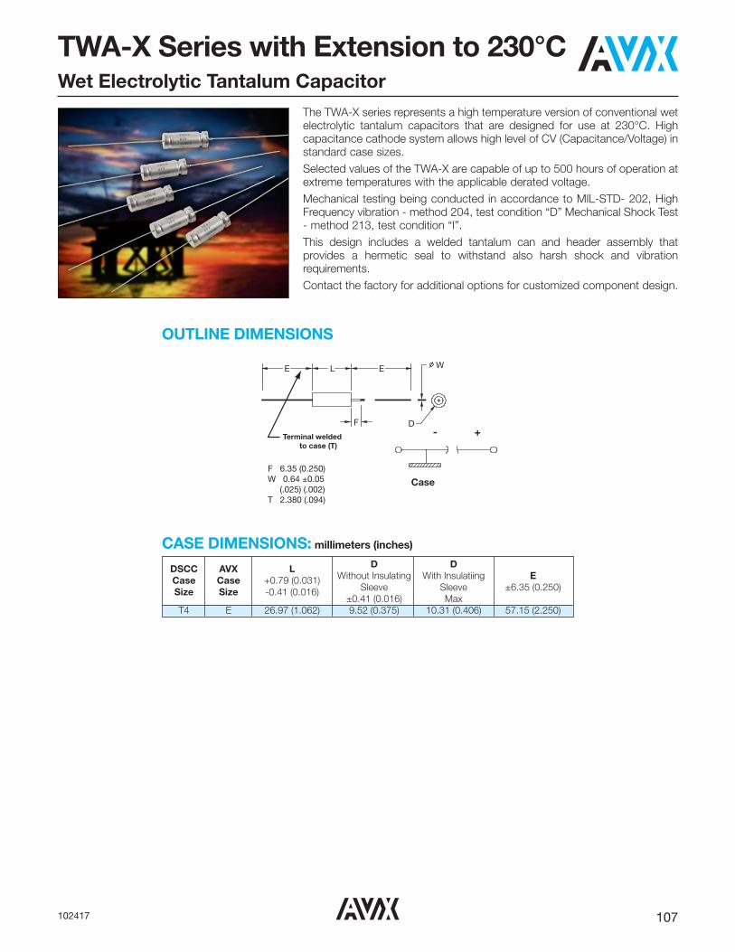
107102417
TWA-X Series with Extension to 230°CWet Electrolytic Tantalum Capacitor
Terminal weldedto case (T)
Case
+-
F 6.35 (0.250)W 0.64 ±0.05 (.025) (.002)T 2.380 (.094)
F D
E WLE
The TWA-X series represents a high temperature version of conventional wetelectrolytic tantalum capacitors that are designed for use at 230°C. Highcapacitance cathode system allows high level of CV (Capacitance/Voltage) instandard case sizes.Selected values of the TWA-X are capable of up to 500 hours of operation atextreme temperatures with the applicable derated voltage.Mechanical testing being conducted in accordance to MIL-STD- 202, HighFrequency vibration - method 204, test condition “D” Mechanical Shock Test- method 213, test condition “I”.This design includes a welded tantalum can and header assembly thatprovides a hermetic seal to withstand also harsh shock and vibrationrequirements.Contact the factory for additional options for customized component design.
OUTLINE DIMENSIONS
DSCC AVX L D D Case Case +0.79 (0.031) Without Insulating With Insulatiing E Size Size -0.41 (0.016) Sleeve Sleeve ±6.35 (0.250) ±0.41 (0.016) Max T4 E 26.97 (1.062) 9.52 (0.375) 10.31 (0.406) 57.15 (2.250)
CASE DIMENSIONS: millimeters (inches)

108 102417
^
TerminationFinish
0 = Sn/Pb 60/407 = Matte tin
*
CapacitanceTolerance
K = ±10%M = ±20%
B
PackagingB = Tray Pack
TWA
Type
E
CaseSize
�
Insulation SleeveC = Without SleeveS = With Sleeve
X
QualificationX = High-Temp up
to 230°C
Z
ReliabilityZ = Non-ER
0
QualificationLevel
0 = N/A
HOW TO ORDERAVX PART NUMBER:
100
VoltageCode
407
CapacitanceCode
pF code: 1st two digits
representsignificant figures 3rd
digit representsmultiplier
(number ofzeros to follow)
00
Custom TestOptions
00 = Standard
Frequency of Applied 120Hz 800Hz 1kHz Ripple Current Ambient Still Air
≤55 85 105 125 ≤55 85 105 125 ≤55 85 105 125 Temperature (ºC) % of 100% 0.60 0.39 – – 0.71 0.43 – – 0.72 0.45 – – 85ºC 90% 0.60 0.46 – – 0.71 0.55 – _ 0.72 0.55 – – Rated 80% 0.60 0.52 0.35 – 0.71 0.62 0.42 – 0.72 0.62 0.42 – Peak 70% 0.60 0.58 0.44 – 0.71 0.69 0.52 – 0.72 0.70 0.52 – Voltage 66-2/3% 0.60 0.60 0.46 0.27 0.71 0.71 0.55 0.32 0.72 0.72 0.55 0.32
Frequency of Applied 10kHz 40kHz 100kHz Ripple Current Ambient Still Air
≤55 85 105 125 ≤55 85 105 125 ≤55 85 105 125 Temperature (ºC) % of 100% 0.88 0.55 – – 1.00 0.63 – – 1.10 0.69 – – 85ºC 90% 0.88 0.67 – – 1.00 0.77 – _ 1.10 0.85 – – Rated 80% 0.88 0.76 0.52 – 1.00 0.87 0.59 – 1.10 0.96 0.65 – Peak 70% 0.88 0.85 0.64 – 1.00 0.97 0.73 – 1.10 1.07 0.80 – Voltage 66-2/3% 0.88 0.88 0.68 0.40 1.00 1.00 0.77 0.45 1.10 1.10 0.85 0.50
1/ At 125ºC the rated voltage of the capacitors decreases to 66 2/3 of the 85ºC rated voltage.2/ The peak of the applied ac ripple voltage plus the applied dc voltage must not exceed the dc voltage rating of the capacitors.
RIPPLE CURRENT MULTIPLIERS vs. Frequency, temperature and applied voltage1/ 2/
LEAD-FREE COMPATIBLECOMPONENT
For RoHS compliant products, please select correct termination style.
TWA-X Series with Extension to 230°CWet Electrolytic Tantalum Capacitor

109102417
TWA-X Series with Extension to 230°CWet Electrolytic Tantalum Capacitor
Capacitance Rated Voltage DC (VR) to 85°C μF Code 75V 100V 125V 220 227 330 337 E 400 407 E 470 477
CAPACITANCE AND RATED VOLTAGE, VR (VOLTAGE CODE) RANGE (LETTER DENOTES CASE SIZE)
Available Ratings
RATINGS & PART NUMBER REFERENCE
DC
DC Leakage
Impedance
Maximum Capacitance AC 85°C
Case Size Cap (uF) Rated
ESR max (μA)
max
change (%)
Ripple Capability 200°C Capability max. 230°C Capability max
AVX Part Number
25°C at Voltage max
(Ohms) (mA rms) max.
120Hz (V)
(Ohms) +85 -55°C
85°C Time at Ur
Time at DCL @Ur
Time at DCL @ AVX DSCC
At 85°C at 120Hz +25ºC &
at 120 Hz -55°C +85°C +125°C at 85ºC
(V)200ºC 200ºC
(V)230ºC 230ºC
+125ºC 40kHz (hrs) (hrs) (μA) (hrs) (μA) TWAE407*100□BXZ0^00 E T4 400 100 0.8 10 150 10 -50 10 35 4100 2000 60 2000 1000 25 500 1000 TWAE337*125□BXZ0^00 E T4 330 125 0.8 10 60 10 -45 15 25 3600 500 75 500 1000 40 500 1000
All technical data relates to an ambient temperature of +25ºC. Capacitance and DF are measured at 120Hz, 0.5RMSwith DC bias of 2.2V. DCL is measured at rated voltage after 5 minutes.NOTE: AVX reserves the rights to supply higher voltage rating in the same case size, to the same reliability standards.
DF = 2πfC x (ESR)2π = 6.28f = 120HzC = Actual measured capacitanceESR = Actual measured ESR

110 040616
TWS Electrolytic Tantalum CapacitorDSCC 13017
Terminal weldedto case (T)
Case
+-
F 6.35 (0.250)W 0.64 +0.05 (.025 +.002)T 2.380 (.094)
F D
E WLE
DSCC AVX L D D E Case Case +0.79 (0.031) Without Insulating With Insulatiing ±6.35 (0.250) Size Size -0.41 (0.016) Sleeve Sleeve ±0.41 (0.016) Max T1 A 11.51 (0.453) 4.78 (0.188) 5.56 (0.219) 38.10 (1.500) T2 B 16.28 (0.641) 7.14 (0.281) 7.92 (0.312) 57.15 (2.250) T3 D 19.46 (0.766) 9.52 (0.375) 10.31 (0.406) 57.15 (2.250) T4 E 26.97 (1.062) 9.52 (0.375) 10.31 (0.406) 57.15 (2.250)
The TWS series, built to the requirements of DSCC 13017, represents a family ofaxial leaded wet tantalum capacitors that encompasses the high capacitance valuesof DSCC 93026 with additional mechanical stability for increased vibration capability.
Vibration Capabilities:Vibration: MIL-PRF-39006, MIL-STD-202, Method 204, Test Condition E, 50 gRandom Vibration: MIL-PRF-39006, MIL-STD-202, Method 214, Test condition II-G, 27.78 gShock: MIL-PRF-39006, MIL-STD-202, Method 213, Condition D, 500 g
Components built to DSCC 13017 also see enhanced thermal shock testing with anincrease from the standard 30 cycles to 300 cycles.
In addition, this family includes reverse voltage testing in accordance with MIL-PRF-39006, with a maximum dc potential of -3 V.
Customized capacitance and voltage packages are possible and welcomed.Contact the factory about design possibilities beyond those contained in thisdatasheet.
CASE DIMENSIONS: millimeters (inches)
OUTLINE DIMENSIONS
Operating Temperature -55ºC to 125ºC

111040616
TWS Electrolytic Tantalum CapacitorDSCC 13017
Frequency of Applied 120Hz 800Hz 1kHz Ripple Current Ambient Still Air
≤55 85 105 125 ≤55 85 105 125 ≤55 85 105 125 Temperature (ºC) % of 100% 0.60 0.39 – – 0.71 0.43 – – 0.72 0.45 – – 85ºC 90% 0.60 0.46 – – 0.71 0.55 – _ 0.72 0.55 – – Rated 80% 0.60 0.52 0.35 – 0.71 0.62 0.42 – 0.72 0.62 0.42 – Peak 70% 0.60 0.58 0.44 – 0.71 0.69 0.52 – 0.72 0.70 0.52 – Voltage 66-2/3% 0.60 0.60 0.46 0.27 0.71 0.71 0.55 0.32 0.72 0.72 0.55 0.32
Frequency of Applied 10kHz 40kHz 100kHz Ripple Current Ambient Still Air
≤55 85 105 125 ≤55 85 105 125 ≤55 85 105 125 Temperature (ºC) % of 100% 0.88 0.55 – – 1.00 0.63 – – 1.10 0.69 – – 85ºC 90% 0.88 0.67 – – 1.00 0.77 – _ 1.10 0.85 – – Rated 80% 0.88 0.76 0.52 – 1.00 0.87 0.59 – 1.10 0.96 0.65 – Peak 70% 0.88 0.85 0.64 – 1.00 0.97 0.73 – 1.10 1.07 0.80 – Voltage 66-2/3% 0.88 0.88 0.68 0.40 1.00 1.00 0.77 0.45 1.10 1.10 0.85 0.50
1/ At 125ºC the rated voltage of the capacitors decreases to 66 2/3 of the 85ºC rated voltage.2/ The peak of the applied ac ripple voltage plus the applied dc voltage must not exceed the dc voltage rating of the capacitors.
HOW TO ORDER AVX PART NUMBER:
RIPPLE CURRENT MULTIPLIERS vs. Frequency, temperature and applied voltage1/ 2/
�
Insulation SleeveU = Without SleeveS = With Sleeve
13017
DrawingNumber
-XX
DashNumber
See RatingTables
*
Capacitance
Tolerance K = ±10%M = ±20%
DSCC PART IDENTIFICATION NUMBER (PIN):LEAD-FREE COMPATIBLE
COMPONENT
For RoHS compliant products, please select correct termination style.
K
CapacitanceTolerance
K = ±10% M = ±20%
B
PackagingB = Tray Pack
00
Standard
TWS
Type
B
CaseSize
A = T1B = T2D = T3E = T4
100
Voltage
686
CapacitanceCode
pF code: 1st two digits
representsignificant figures 3rd
digit representsmultiplier
(number ofzeros to follow)
Z
ReliabilityZ = Non-ER
00
TerminationFinish
00 = Sn /Pb 60/4007 = 100% Tin
#
QualificationS = Std. Conformance
D = DSCCL = Group A9 = SRW9000
�
Insulation SleeveC = Without SleeveS = With Sleeve
K
CapacitanceTolerance
K = ±10% M = ±20%
B
PackagingB = Tray Pack
00
Custom TestOptions
00 = Standard
TWS
Type
B 100
VoltageCode
686
CapacitanceCode
pF code: 1st two digits
representsignificant figures 3rd
digit representsmultiplier
(number ofzeros to follow)
Z
ReliabilityZ = Non-ER
9
QualificationLevel9 =
SRW9000
0
TerminationFinish
0 = Sn /Pb60/40
#
QualificationL = Group A
�
Insulation SleeveC = Without SleeveS = With Sleeve
SPACE LEVEL OPTIONS TO SRW9000*:
Not RoHS Compliant
*Check with factory for availability and testing details.

112 040616
TWS Electrolytic Tantalum CapacitorDSCC 13017
RATINGS & PART NUMBER REFERENCEAVX DSCC
Cap DC Rated ESR DC Leakage max Impedance Maximum Capacitance AC Ripple Case Size
Part Part (μF) Voltage max (μA) max (Ohms) Change (%) (mA rms)
Number Number 25ºC (V) (ohms)
+25ºC+85ºC -55ºC
-55ºC +85ºC +125ºC 85ºC
AVX DSCC at 120Hz at 85ºC at 120Hz & +125ºC at 120Hz at 40kHz25 VDC at 85ºC 15 VDC at 125ºC
TWSB567*025�B#Z0000 13017-02*� 560 25 0.83 2 10 12 -65 14 18 2000 B T2TWSD128*025�B#Z0000 13017-03*� 1200 25 0.65 5 20 7 -70 15 20 2400 D T3TWSE188*025�B#Z0000 13017-04*� 1800 25 0.5 6 25 7 -72 15 20 3000 E T4
30 VDC at 85°C 20 VDC at 125°CTWSB477*030�B#Z0000 13017-06*� 470 30 0.85 2 10 15 -65 14 18 1800 B T2TWSD108*030�B#Z0000 13017-07*� 1000 30 0.7 7 25 7 -70 15 25 2200 D T3TWSE158*030�B#Z0000 13017-08*� 1500 30 0.6 12 35 6 -72 15 25 2900 E T4
50 VDC at 85°C 30 VDC at 125°CTWSB227*050�B#Z0000 13017-10*� 220 50 0.9 2 10 17.5 -50 8 15 1800 B T2TWSE687*050�B#Z0000 13017-12*� 680 50 0.7 5 40 8 -58 10 20 2700 E T4
60V VDC at 85°C 40 VDC at 125°CTWSB157*060�B#Z0000 13017-14*� 150 60 1.1 2 10 20 -40 8 15 1800 B T2TWSE567*060�B#Z0000 13017-16*� 560 60 0.8 5 40 10 -58 8 15 2700 E T4
75V VDC at 85°C 50 VDC at 125°CTWSA336*075�B#Z0000 13017-17*� 33 75 2.5 1 5 66 -25 5 9 1050 A T1TWSB117*075�B#Z0000 13017-18*� 110 75 1.3 2 10 24 -35 6 10 1650 B T2TWSE477*075�B#Z0000 13017-20*� 470 75 0.9 5 50 12 -50 6 10 2700 E T4
100 VDC at 85°C 65 VDC at 125°CTWSA156*100�B#Z0000 13017-21*� 15 100 3.5 1 5 125 -18 3 10 1050 A T1TWSB686*100�B#Z0000 13017-22*� 68 100 2.1 2 10 37 -30 4 12 1650 B T2TWSE227*100�B#Z0000 13017-24*� 220 100 1.2 5 50 15 -40 6 12 2700 E T4
All technical data relates to an ambient temperature of +25ºC. Capacitance and DF are measured at 120Hz, 0.5RMS with DC bias of 2.2V. DCL is measured at rated voltage after 5 minutes.
NOTE: AVX reserves the rights to supply higher voltage rating in the same case size, to the same reliability standards.
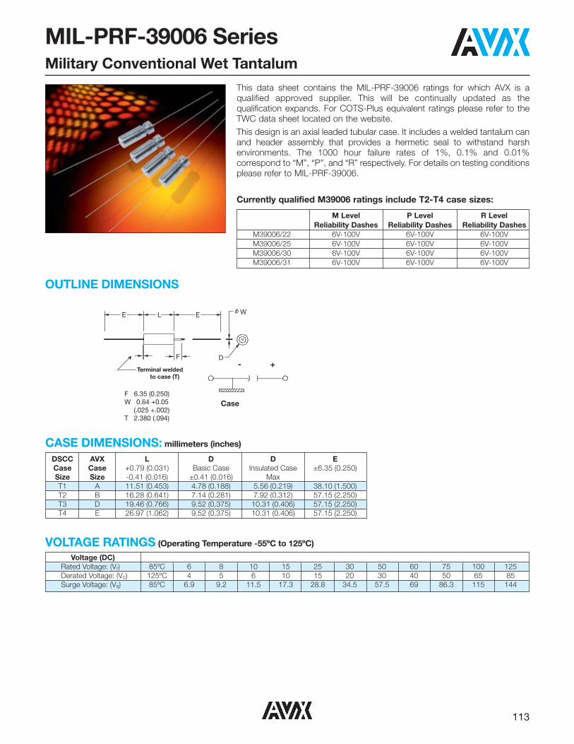
113
MIL-PRF-39006 SeriesMilitary Conventional Wet Tantalum
Terminal weldedto case (T)
Case
+-
F 6.35 (0.250)W 0.64 +0.05 (.025 +.002)T 2.380 (.094)
F D
E WLE
DSCC AVX L D D E Case Case +0.79 (0.031) Basic Case Insulated Case ±6.35 (0.250) Size Size -0.41 (0.016) ±0.41 (0.016) Max T1 A 11.51 (0.453) 4.78 (0.188) 5.56 (0.219) 38.10 (1.500) T2 B 16.28 (0.641) 7.14 (0.281) 7.92 (0.312) 57.15 (2.250) T3 D 19.46 (0.766) 9.52 (0.375) 10.31 (0.406) 57.15 (2.250) T4 E 26.97 (1.062) 9.52 (0.375) 10.31 (0.406) 57.15 (2.250)
This data sheet contains the MIL-PRF-39006 ratings for which AVX is aqualified approved supplier. This will be continually updated as thequalification expands. For COTS-Plus equivalent ratings please refer to theTWC data sheet located on the website.This design is an axial leaded tubular case. It includes a welded tantalum canand header assembly that provides a hermetic seal to withstand harshenvironments. The 1000 hour failure rates of 1%, 0.1% and 0.01%correspond to “M”, “P”, and “R” respectively. For details on testing conditionsplease refer to MIL-PRF-39006.
Currently qualified M39006 ratings include T2-T4 case sizes:
CASE DIMENSIONS: millimeters (inches)
OUTLINE DIMENSIONS
Voltage (DC) Rated Voltage: (Vr) 85ºC 6 8 10 15 25 30 50 60 75 100 125Derated Voltage: (Vc) 125ºC 4 5 6 10 15 20 30 40 50 65 85Surge Voltage: (Vs) 85ºC 6.9 9.2 11.5 17.3 28.8 34.5 57.5 69 86.3 115 144
VOLTAGE RATINGS (Operating Temperature -55ºC to 125ºC)
M Level P Level R Level Reliability Dashes Reliability Dashes Reliability Dashes
M39006/22 6V-100V 6V-100V 6V-100VM39006/25 6V-100V 6V-100V 6V-100VM39006/30 6V-100V 6V-100V 6V-100VM39006/31 6V-100V 6V-100V 6V-100V

114
M39006
Type / MilitaryDesignator
HOW TO ORDER MILITARY M39006 PART NUMBER:–0081
DashNumber
–
*H = High Vibration(When Specified)
/22
SpecificationSheet
Number
Not RoHS Compliant
MIL-PRF-39006 SeriesMilitary Conventional Wet Tantalum
Frequency of Applied 120Hz 800Hz 1kHz Ripple Current Ambient Still Air
≤55 85 105 125 ≤55 85 105 125 ≤55 85 105 125 Temperature (ºC) % of 100% 0.60 0.39 – – 0.71 0.43 – – 0.72 0.45 – – 85ºC 90% 0.60 0.46 – – 0.71 0.55 – _ 0.72 0.55 – – Rated 80% 0.60 0.52 0.35 – 0.71 0.62 0.42 – 0.72 0.62 0.42 – Peak 70% 0.60 0.58 0.44 – 0.71 0.69 0.52 – 0.72 0.70 0.52 – Voltage 66-2/3% 0.60 0.60 0.46 0.27 0.71 0.71 0.55 0.32 0.72 0.72 0.55 0.32
Frequency of Applied 10kHz 40kHz 100kHz Ripple Current Ambient Still Air
≤55 85 105 125 ≤55 85 105 125 ≤55 85 105 125 Temperature (ºC) % of 100% 0.88 0.55 – – 1.00 0.63 – – 1.10 0.69 – – 85ºC 90% 0.88 0.67 – – 1.00 0.77 – _ 1.10 0.85 – – Rated 80% 0.88 0.76 0.52 – 1.00 0.87 0.59 – 1.10 0.96 0.65 – Peak 70% 0.88 0.85 0.64 – 1.00 0.97 0.73 – 1.10 1.07 0.80 – Voltage 66-2/3% 0.88 0.88 0.68 0.40 1.00 1.00 0.77 0.45 1.10 1.10 0.85 0.50
1/ At 125ºC the rated voltage of the capacitors decreases to 66 2/3 of the 85ºC rated voltage.2/ The peak of the applied ac ripple voltage plus the applied dc voltage must not exceed the dc voltage rating of the capacitors.3/ The ripple current listed in the parametric tables represents a rating calculated by using a maximum internal temperature rise (ΔT) at
50°C at 40 kHz at 85°C ambient temperature, with a maximum peak rated voltage of 66.67 percent of the 85°C peak voltage rating.
RIPPLE CURRENT MULTIPLIERS vs. Frequency, temperature and applied voltage1/ 2/ 3/
*High vibration qualified parts are currently under development. Please contact the factory for additional details and availability.

115
M39006 /22 RATINGS AND DASH NUMBER REFERENCEM39006/22 Dashes Cap DC Rated DC Leakage (μA) ESR Impedance Maximum Capacitance AC Ripple
Tolerance ±(μF) Voltage DF max max Change (%) (mA rms) Case
M P R(%)
25°C (V) +85ºC max (Ohms) (Ohms) 85ºC SizeLevel Level Level at at +25ºC & (%) at -55ºC at -55ºC +85ºC +125ºC at
120Hz 85ºC +125ºC 120Hz 120Hz 40kHz-0007 -0227 -0447 20-0008 -0228 -0448 10 140 6 1 3 21 1.99 40 -40 14 16 1200 T2-0009 -0229 -0449 5-0010 -0230 -0450 20-0011 -0231 -0451 10 270 6 1 6.5 45 2.21 25 -44 17.5 20 1375 T2-0012 -0232 -0452 5-0013 -0233 -0453 20-0014 -0234 -0454 10 330 6 2 7.9 36 1.45 20 -44 14 16 1800 T3-0015 -0235 -0455 5-0016 -0236 -0456 20-0017 -0237 -0457 10 560 6 2 13 55 1.3 25 -64 17.5 20 1900 T3-0018 -0238 -0458 5-0019 -0239 -0459 20 1200 6 3 14 90 1 20 -80 25 25 2265 T4-0020 -0240 -0460 10-0027 -0247 -0467 20-0028 -0248 -0468 10 120 8 1 2 20 2.21 50 -44 17.5 20 1220 T2-0029 -0249 -0469 5-0030 -0250 -0470 20-0031 -0251 -0471 10 220 8 1 7 37 2.23 30 -44 17.5 20 1370 T2-0032 -0252 -0472 5-0033 -0253 -0473 20-0034 -0254 -0474 10 290 8 2 6 34 1.56 25 -64 17.5 20 1770 T3-0035 -0255 -0475 5-0036 -0256 -0476 20-0037 -0257 -0477 10 430 8 2 14 46 1.42 25 -64 17.5 20 1825 T3-0038 -0258 -0478 5-0039 -0259 -0479 20 850 8 4 16 60 0.94 22 -80 25 25 2330 T4-0040 -0260 -0480 10-0047 -0267 -0487 20-0048 -0268 -0488 10 100 10 1 4 15 1.99 60 -36 14 16 1200 T2-0049 -0269 -0489 5-0050 -0270 -0490 20-0051 -0271 -0491 10 180 10 1 7 30 2.21 40 -36 14 16 1.365 T2-0052 -0272 -0492 5-0053 -0273 -0493 20-0054 -0274 -0494 10 250 10 2 10 30 1.59 30 -40 14 16 1720 T3-0055 -0275 -0495 5-0056 -0276 -0496 20-0057 -0277 -0497 10 390 10 2 16 44 1.5 25 -64 17.5 20 1800 T3-0058 -0278 -0498 5-0059 -0279 -0499 20 750 10 4 16 50 0.88 23 -80 25 25 2360 T4-0060 -0280 -0500 10-0067 -0287 -0507 20-0068 -0288 -0508 10 70 15 1 4 13 2.46 75 -28 14 16 1150 T2-0069 -0289 -0509 5-0070 -0290 -0510 20-0071 -0291 -0511 10 120 15 1 7 18 1.99 50 -28 17.5 20 1450 T2-0072 -0292 -0512 5-0073 -0293 -0513 20-0074 -0294 -0514 10 170 15 2 10 25 1.95 35 -32 14 16 1480 T3-0075 -0295 -0515 5-0076 -0296 -0516 20-0077 -0297 -0517 10 270 15 2 16 32 1.57 30 -56 17.5 20 1740 T3-0078 -0298 -0518 5-0079 -0299 -0519 20 540 15 6 24 40 0.98 23 -80 25 25 2330 T4-0080 -0300 -0520 10-0087 -0307 -0527 20-0088 -0308 -0528 10 50 25 1 2 11 2.92 70 -28 13 15 1130 T2-0089 -0309 -0529 5-0090 -0310 -0530 20-0091 -0311 -0531 10 100 25 1 10 15 1.99 50 -28 13 15 1435 T2-0092 -0312 -0532 5-0093 -0313 -0533 20-0094 -0314 -0534 10 120 25 2 6 21 2.32 38 -32 13 15 1450 T3-0095 -0315 -0535 5-0096 -0316 -0536 20-0097 -0317 -0537 10 180 25 2 18 26 1.92 32 -48 13 15 1525 T3-0098 -0318 -0538 5
All technical data relates to an ambient temperature of +25ºC. Capacitance and DF are measured at 120Hz, 0.5RMS with DC bias of 2.2V. DCL is measured at rated voltage after 5 minutes.
MIL-PRF-39006 SeriesMilitary Conventional Wet Tantalum

116
MIL-PRF-39006 SeriesMilitary Conventional Wet Tantalum
M39006/22 Dashes Cap DC Rated DC Leakage (μA) ESR Impedance Maximum Capacitance AC Ripple
Tolerance ±(μF) Voltage DF max max Change (%) (mA rms) Case
M P R(%)
25°C (V) +85ºC max (Ohms) (Ohms) 85ºC SizeLevel Level Level at at +25ºC & (%) at -55ºC at -55ºC +85ºC +125ºC at
120Hz 85ºC +125ºC 120Hz 120Hz 40kHz-0099 -0319 -0539 20 350 25 7 28 35 1.33 24 -70 25 25 1970 T4-0100 -0320 -0540 10-0107 -0327 -0547 20-0108 -0328 -0548 10 40 30 1 5 10 3.32 65 -24 10.5 12 1120 T2-0109 -0329 -0549 5-0110 -0330 -0550 20-0111 -0331 -0551 10 68 30 1 8 13 2.54 60 -24 13 15 1285 T2-0112 -0332 -0552 5-0113 -0333 -0553 20-0114 -0334 -0554 10 100 30 2 12 17 2.26 40 -28 10.5 12 1450 T3-0115 -0335 -0555 5-0116 -0336 -0556 20-0117 -0337 -0557 10 150 30 2 18 23 2.03 35 -48 13 15 1525 T3-0118 -0338 -0558 5-0119 -0339 -0559 20 300 30 8 32 31 1.37 25 -60 25 25 1950 T4-0120 -0340 -0560 10-0127 -0347 -0567 20-0128 -0348 -0568 10 25 50 1 5 8 4.25 95 -20 10.5 12 1005 T2-0129 -0349 -0569 5-0130 -0350 -0570 20-0131 -0351 -0571 10 47 50 1 9 11 3.11 70 -28 13 15 1155 T2-0132 -0352 -0572 5-0133 -0353 -0573 20-0134 -0354 -0574 10 60 50 2 12 12 2.65 45 -16 10.5 12 1335 T3-0135 -0355 -0575 5-0136 -0356 -0576 20-0137 -0357 -0577 10 82 50 2 16 15 2.43 45 -32 13 15 1400 T3-0138 -0358 -0578 5-0139 -0359 -0579 20 160 50 8 32 17 1.41 27 -50 25 25 1900 T4-0140 -0360 -0580 10-0147 -0367 -0587 20-0148 -0368 -0588 10 20 60 1 5 7 4.64 105 -16 10.5 12 930 T2-0149 -0369 -0589 5-0150 -0370 -0590 20-0151 -0371 -0591 10 39 60 1 9 10 3.4 90 -28 10.5 12 1110 T2-0152 -0372 -0592 5-0153 -0373 -0593 20-0154 -0374 -0594 10 50 60 2 12 10 2.65 50 -16 10.5 12 1330 T3-0155 -0375 -0595 5-0156 -0376 -0596 20-0157 -0377 -0597 10 68 60 2 16 13 2.54 50 -32 10.5 12 1365 T3-0158 -0378 -0598 5-0159 -0379 -0599 20 140 60 8 32 16 1.52 28 -40 20 20 1850 T4-0160 -0380 -0600 10-0167 -0387 -0607 20-0168 -0388 -0608 10 15 75 1 5 6 5.31 150 -16 8 9 890 T2-0169 -0389 -0609 5-0170 -0390 -0610 20-0171 -0391 -0611 10 33 75 1 10 10 4.02 90 -24 10.5 15 1000 T2-0172 -0392 -0612 5-0173 -0393 -0613 20-0174 -0394 -0614 10 40 75 2 12 9 2.99 60 -16 10.5 12 1250 T3-0175 -0395 -0615 5-0176 -0396 -0616 20-0177 -0397 -0617 10 56 75 2 17 11 2.61 60 -28 10.5 15 1335 T3-0178 -0398 -0618 5-0179 -0399 -0619 20 110 75 9 36 12 1.45 29 -35 20 20 1850 T4-0180 -0400 -0620 10-0187 -0407 -0627 20-0188 -0408 -0628 10 11 100 1 4 5 6.03 200 -16 8 8 835 T2-0189 -0409 -0629 5-0190 -0410 -0630 20-0191 -0411 -0631 10 22 100 1 9 7.5 4.52 100 -16 8 8 965 T2-0192 -0412 -0632 5-0193 -0413 -0633 20-0194 -0414 -0634 10 30 100 2 12 7 3.1 80 -16 8 8 1240 T3-0195 -0415 -0635 5-0196 -0416 -0636 20-0197 -0417 -0637 10 43 100 2 17 8.5 2.62 70 -20 8 8 1335 T3-0198 -0418 -0638 5-0199 -0419 -0639 20 86 100 9 36 10 1.54 30 -25 15 15 1800 T4-0200 -0420 -0640 10
All technical data relates to an ambient temperature of +25ºC. Capacitance and DF are measured at 120Hz, 0.5RMS with DC bias of 2.2V. DCL is measured at rated voltage after 5 minutes.

117
MIL-PRF-39006 SeriesMilitary Conventional Wet Tantalum
M39006/25 RATINGS AND DASH NUMBER REFERENCEM39006/25 Dashes Cap DC Rated DC Leakage (μA) ESR Impedance Maximum Capacitance AC Ripple
Tolerance ±(μF) Voltage DF max max Change (%) (mA rms) Case
M P R(%)
25°C (V) +85ºC max (Ohms) (Ohms) 85ºC SizeLevel Level Level at at +25ºC & (%) at -55ºC at -55ºC +85ºC +125ºC at
120Hz 85ºC +125ºC 120Hz 120Hz 40kHz-0003 -0091 -0179 20 820 6 3 14 155 2.51 18 -88 16 20 1500 T2-0004 -0092 -0180 10-0005 -0093 -0181 20 1500 6 5 20 172 1.52 18 -90 20 25 1900 T3-0006 -0094 -0182 10-0007 -0095 -0183 20 2200 6 6 24 170 1.03 13 -90 25 30 2300 T4-0008 -0096 -0184 10-0011 -0099 -0187 20 680 8 3 14 130 2.54 22 -83 16 20 1500 T2-0012 -0100 -0188 10-0013 -0101 -0189 20 1500 8 5 20 170 1.5 18 -90 20 25 1900 T3-0014 -0102 -0190 10-0015 -0103 -0191 20 1800 8 7 25 138 1.02 14 -90 25 30 2300 T4-0016 -0104 -0192 10-0019 -0107 -0195 20 560 10 3 16 106 2.51 27 -77 16 20 1450 T2-0020 -0108 -0196 10-0021 -0109 -0197 20 1200 10 5 20 137 1.51 18 -88 20 25 1850 T3-0022 -0110 -0198 10-0023 -0111 -0199 20 1500 10 7 25 114 1.01 15 -88 25 30 2300 T4-0024 -0112 -0200 10-0027 -0115 -0203 20 390 15 3 16 74 2.52 31 -66 16 20 1450 T2-0028 -0116 -0204 10-0029 -0117 -0205 20 820 15 6 24 111 1.8 22 -77 20 25 1800 T3-0030 -0118 -0206 10-0031 -0119 -0207 20 1000 15 8 32 92 1.22 17 -77 25 30 2300 T4-0032 -0120 -0208 10-0035 -0123 -0211 20 270 25 3 16 55 2.7 33 -62 13 16 1400 T2-0036 -0124 -0212 10-0037 -0125 -0213 20 560 25 7 28 76 1.8 24 -72 20 25 1750 T3-0038 -0126 -0214 10-0039 -0127 -0215 20 680 25 8 32 63 1.23 19 -72 25 30 2100 T4-0040 -0128 -0216 10-0043 -0131 -0219 20 220 30 3 16 42 2.53 36 -60 13 16 1200 T2-0044 -0132 -0220 10-0045 -0133 -0221 20 470 30 8 32 64 1.81 25 -65 20 25 1500 T3-0046 -0134 -0222 10-0047 -0135 -0223 20 560 30 9 36 55 1.3 20 -65 25 30 2000 T4-0048 -0136 -0224 10-0051 -0139 -0227 20 120 50 4 24 22.5 2.49 49 -42 12 15 1200 T2-0052 -0140 -0228 10-0053 -0141 -0229 20 270 50 8 32 37 1.82 29 -46 20 25 1450 T3-0054 -0142 -0230 10-0055 -0143 -0231 20 330 50 9 36 38 1.53 22 -46 25 30 1900 T4-0056 -0144 -0232 10-0059 -0147 -0235 20 100 60 4 20 19 2.52 54 -36 12 15 1100 T2-0060 -0148 -0236 10-0061 -0149 -0237 20 220 60 8 32 30 1.81 29 -40 16 20 1400 T3-0062 -0150 -0238 10-0063 -0151 -0239 20 270 60 9 36 27 1.33 23 -45 20 25 1850 T4-0064 -0152 -0240 10-0067 -0155 -0243 20 82 75 4 24 15.2 2.46 63 -30 12 15 1000 T2-0068 -0156 -0244 10-0069 -0157 -0245 20 180 75 9 36 24.4 2.23 30 -35 16 20 1300 T3-0070 -0158 -0246 10-0071 -0159 -0247 20 220 75 10 40 37 1.8 24 -40 20 25 1800 T4-0072 -0160 -0248 10-0075 -0163 -0251 20 39 100 5 24 10.4 3.54 80 -20 12 15 1300 T2-0076 -0164 -0252 10-0077 -0165 -0253 20 68 100 10 40 11.3 2.21 40 -30 14 16 1600 T3-0078 -0166 -0254 10-0079 -0167 -0255 20 120 100 12 48 25 2.76 30 -35 15 17 2000 T4-0080 -0168 -0256 10
All technical data relates to an ambient temperature of +25ºC. Capacitance and DF are measured at 120Hz, 0.5RMS with DC bias of 2.2V. DCL is measured at rated voltage after 5 minutes.

118
MIL-PRF-39006 SeriesMilitary Conventional Wet Tantalum
M39006 /30 RATINGS AND DASH NUMBER REFERENCEM39006/30 Dashes Cap DC Rated DC Leakage (μA) ESR Impedance Maximum Capacitance AC Ripple
Tolerance ±(μF) Voltage DF max max Change (%) (mA rms) Case
M P R(%)
25°C (V) +85ºC max (Ohms) (Ohms) 85ºC SizeLevel Level Level at at +25ºC & (%) at -55ºC at -55ºC +85ºC +125ºC at
120Hz 85ºC +125ºC 120Hz 120Hz 40kHz-0007 -0227 -0447 20-0008 -0228 -0448 10 140 6 1 3 10.5 0.99 40 -40 14 16 1200 T2-0009 -0229 -0449 5-0010 -0230 -0450 20-0011 -0231 -0451 10 270 6 1 6.5 22.5 1.11 25 -44 17.5 20 1375 T2-0012 -0232 -0452 5-0013 -0233 -0453 20-0014 -0234 -0454 10 330 6 2 7.9 18 0.73 20 -44 14 16 1800 T3-0015 -0235 -0455 5-0016 -0236 -0456 20-0017 -0237 -0457 10 560 6 2 13 27.5 0.65 25 -64 17.5 20 1900 T3-0018 -0238 -0458 5-0019 -0239 -0459 20 1200 6 3 14 45 0.5 20 -80 25 25 2265 T4-0020 -0240 -0460 10-0027 -0247 -0467 20-0028 -0248 -0468 10 120 8 1 2 10 1.11 50 -44 17.5 20 1220 T2-0029 -0249 -0469 5-0030 -0250 -0470 20-0031 -0251 -0471 10 220 8 1 7 18.5 1.12 30 -44 17.5 20 1370 T2-0032 -0252 -0472 5-0033 -0253 -0473 20-0034 -0254 -0474 10 290 8 2 6 17 0.78 25 -64 17.5 20 1770 T3-0035 -0255 -0475 5-0036 -0256 -0476 20-0037 -0257 -0477 10 430 8 2 14 23 0.71 25 -64 17.5 20 1825 T3-0038 -0258 -0478 5-0039 -0259 -0479 20 850 8 4 16 30 0.47 22 -80 25 25 2330 T4-0040 -0260 -0480 10-0047 -0267 -0487 20-0048 -0268 -0488 10 100 10 1 4 7.5 0.99 60 -36 14 16 1200 T2-0049 -0269 -0489 5-0050 -0270 -0490 20-0051 -0271 -0491 10 180 10 1 7 15 1.11 40 -36 14 16 1.365 T2-0052 -0272 -0492 5-0053 -0273 -0493 20-0054 -0274 -0494 10 250 10 2 10 15 0.8 30 -40 14 16 1720 T3-0055 -0275 -0495 5-0056 -0276 -0496 20-0057 -0277 -0497 10 390 10 2 16 22 0.75 25 -64 17.5 20 1800 T3-0058 -0278 -0498 5-0059 -0279 -0499 20 750 10 4 16 25 0.44 23 -80 25 25 2360 T4-0060 -0280 -0500 10-0067 -0287 -0507 20-0068 -0288 -0508 10 70 15 1 4 6.5 1.23 75 -28 14 16 1150 T2-0069 -0289 -0509 5-0070 -0290 -0510 20-0071 -0291 -0511 10 120 15 1 7 9 0.99 50 -28 17.5 20 1450 T2-0072 -0292 -0512 5-0073 -0293 -0513 20-0074 -0294 -0514 10 170 15 2 10 12.5 0.98 35 -32 14 16 1480 T3-0075 -0295 -0515 5-0076 -0296 -0516 20-0077 -0297 -0517 10 270 15 2 16 16 0.79 30 -56 17.5 20 1740 T3-0078 -0298 -0518 5-0079 -0299 -0519 20 540 15 6 24 20 0.49 23 -80 25 25 2330 T4-0080 -0300 -0520 10-0087 -0307 -0527 20-0088 -0308 -0528 10 50 25 1 2 5.5 1.46 70 -28 13 15 1130 T2-0089 -0309 -0529 5-0090 -0310 -0530 20-0091 -0311 -0531 10 100 25 1 10 7.5 0.99 50 -28 13 15 1435 T2-0092 -0312 -0532 5-0093 -0313 -0533 20-0094 -0314 -0534 10 120 25 2 6 10.5 1.16 38 -32 13 15 1450 T3-0095 -0315 -0535 5-0096 -0316 -0536 20-0097 -0317 -0537 10 180 25 2 18 13 0.96 32 -48 13 15 1525 T3-0098 -0318 -0538 5
All technical data relates to an ambient temperature of +25ºC. Capacitance and DF are measured at 120Hz, 0.5RMS with DC bias of 2.2V. DCL is measured at rated voltage after 5 minutes.

119
MIL-PRF-39006 SeriesMilitary Conventional Wet Tantalum
M39006/30 Dashes Cap DC Rated DC Leakage (μA) ESR Impedance Maximum Capacitance AC Ripple
Tolerance ±(μF) Voltage DF max max Change (%) (mA rms) Case
M P R(%)
25°C (V) +85ºC max (Ohms) (Ohms) 85ºC SizeLevel Level Level at at +25ºC & (%) at -55ºC at -55ºC +85ºC +125ºC at
120Hz 85ºC +125ºC 120Hz 120Hz 40kHz-0099 -0319 -0539 20 350 25 7 28 17.5 0.67 24 -70 25 25 1970 T4-0100 -0320 -0540 10-0107 -0327 -0547 20-0108 -0328 -0548 10 40 30 1 5 5 1.66 65 -24 10.5 12 1120 T2-0109 -0329 -0549 5-0110 -0330 -0550 20-0111 -0331 -0551 10 68 30 1 8 6.5 1.27 60 -24 13 15 1285 T2-0112 -0332 -0552 5-0113 -0333 -0553 20-0114 -0334 -0554 10 100 30 2 12 8.5 1.13 40 -28 10.5 12 1450 T3-0115 -0335 -0555 5-0116 -0336 -0556 20-0117 -0337 -0557 10 150 30 2 18 11.5 1.02 35 -48 13 15 1525 T3-0118 -0338 -0558 5-0119 -0339 -0559 20 300 30 8 32 15.5 0.69 25 -60 25 25 1950 T4-0120 -0340 -0560 10-0127 -0347 -0567 20-0128 -0348 -0568 10 25 50 1 5 4 2.13 95 -20 10.5 12 1005 T2-0129 -0349 -0569 5-0130 -0350 -0570 20-0131 -0351 -0571 10 47 50 1 9 5.5 1.56 70 -28 13 15 1155 T2-0132 -0352 -0572 5-0133 -0353 -0573 20-0134 -0354 -0574 10 60 50 2 12 6 1.33 45 -16 10.5 12 1335 T3-0135 -0355 -0575 5-0136 -0356 -0576 20-0137 -0357 -0577 10 82 50 2 16 7.5 1.22 45 -32 13 15 1400 T3-0138 -0358 -0578 5-0139 -0359 -0579 20 160 50 8 32 8.5 0.71 27 -50 25 25 1900 T4-0140 -0360 -0580 10-0147 -0367 -0587 20-0148 -0368 -0588 10 20 60 1 5 3.5 2.32 105 -16 10.5 12 930 T2-0149 -0369 -0589 5-0150 -0370 -0590 20-0151 -0371 -0591 10 39 60 1 9 5 1.7 90 -28 10.5 12 1110 T2-0152 -0372 -0592 5-0153 -0373 -0593 20-0154 -0374 -0594 10 50 60 2 12 5 1.33 50 -16 10.5 12 1330 T3-0155 -0375 -0595 5-0156 -0376 -0596 20-0157 -0377 -0597 10 68 60 2 16 6.5 1.27 50 -32 10.5 12 1365 T3-0158 -0378 -0598 5-0159 -0379 -0599 20 140 60 8 32 8 0.76 28 -40 20 20 1850 T4-0160 -0380 -0600 10-0167 -0387 -0607 20-0168 -0388 -0608 10 15 75 1 5 3 2.66 150 -16 8 9 890 T2-0169 -0389 -0609 5-0170 -0390 -0610 20-0171 -0391 -0611 10 33 75 1 10 5 2.01 90 -24 10.5 15 1000 T2-0172 -0392 -0612 5-0173 -0393 -0613 20-0174 -0394 -0614 10 40 75 2 12 4.5 1.5 60 -16 10.5 12 1250 T3-0175 -0395 -0615 5-0176 -0396 -0616 20-0177 -0397 -0617 10 56 75 2 17 5.5 1.31 60 -28 10.5 15 1335 T3-0178 -0398 -0618 5-0179 -0399 -0619 20 110 75 9 36 6 0.73 29 -35 20 20 1850 T4-0180 -0400 -0620 10-0187 -0407 -0627 20-0188 -0408 -0628 10 11 100 1 4 2.5 3.02 200 -16 8 8 835 T2-0189 -0409 -0629 5-0190 -0410 -0630 20-0191 -0411 -0631 10 22 100 1 9 3.75 2.26 100 -16 8 8 965 T2-0192 -0412 -0632 5-0193 -0413 -0633 20-0194 -0414 -0634 10 30 100 2 12 3.5 1.55 80 -16 8 8 1240 T3-0195 -0415 -0635 5-0196 -0416 -0636 20-0197 -0417 -0637 10 43 100 2 17 4.25 1.31 70 -20 8 8 1335 T3-0198 -0418 -0638 5-0199 -0419 -0639 20 86 100 9 36 5 0.77 30 -25 15 15 1800 T4-0200 -0420 -0640 10
All technical data relates to an ambient temperature of +25ºC. Capacitance and DF are measured at 120Hz, 0.5RMS with DC bias of 2.2V. DCL is measured at rated voltage after 5 minutes.All technical data relates to an ambient temperature of +25ºC. Capacitance and DF are measured at 120Hz, 0.5RMS with DC bias of 2.2V. DCL is measured at rated voltage after 5 minutes.

120
MIL-PRF-39006 SeriesMilitary Conventional Wet Tantalum
M39006 /31 RATINGS AND DASH NUMBER REFERENCEM39006/31 Dashes Cap DC Rated DC Leakage (μA) ESR Impedance Maximum Capacitance AC Ripple
Tolerance ±(μF) Voltage DF max max Change (%) (mA rms) Case
M P R(%)
25°C (V) +85ºC max (Ohms) (Ohms) 85ºC SizeLevel Level Level at at +25ºC & (%) at -55ºC at -55ºC +85ºC +125ºC at
120Hz 85ºC +125ºC 120Hz 120Hz 40kHz-0003 -0091 -0179 20 820 6 3 14 77.5 1.26 18 -88 16 20 1500 T2-0004 -0092 -0180 10-0005 -0093 -0181 20 1500 6 5 20 86 0.76 18 -90 20 25 1900 T3-0006 -0094 -0182 10-0007 -0095 -0183 20 2200 6 6 24 85 0.52 13 -90 25 30 2300 T4-0008 -0096 -0184 10-0011 -0099 -0187 20 680 8 3 14 65 1.27 22 -83 16 20 1500 T2-0012 -0100 -0188 10-0013 -0101 -0189 20 1500 8 5 20 85 0.75 18 -90 20 25 1900 T3-0014 -0102 -0190 10-0015 -0103 -0191 20 1800 8 7 25 69 0.51 14 -90 25 30 2300 T4-0016 -0104 -0192 10-0019 -0107 -0195 20 560 10 3 16 53 1.26 27 -77 16 20 1450 T2-0020 -0108 -0196 10-0021 -0109 -0197 20 1200 10 5 20 68.5 0.76 18 -88 20 25 1850 T3-0022 -0110 -0198 10-0023 -0111 -0199 20 1500 10 7 25 57 0.51 15 -88 25 30 2300 T4-0024 -0112 -0200 10-0027 -0115 -0203 20 390 15 3 16 37 1.26 31 -66 16 20 1450 T2-0028 -0116 -0204 10-0029 -0117 -0205 20 820 15 6 24 55.5 0.9 22 -77 20 25 1800 T3-0030 -0118 -0206 10-0031 -0119 -0207 20 1000 15 8 32 46 0.61 17 -77 25 30 2300 T4-0032 -0120 -0208 10-0035 -0123 -0211 20 270 25 3 16 27.5 1.35 33 -62 13 16 1400 T2-0036 -0124 -0212 10-0037 -0125 -0213 20 560 25 7 28 38 0.9 24 -72 20 25 1750 T3-0038 -0126 -0214 10-0039 -0127 -0215 20 680 25 8 32 31.5 0.62 19 -72 25 30 2100 T4-0040 -0128 -0216 10-0043 -0131 -0219 20 220 30 3 16 21 1.27 36 -60 13 16 1200 T2-0044 -0132 -0220 10-0045 -0133 -0221 20 470 30 8 32 32 0.91 25 -65 20 25 1500 T3-0046 -0134 -0222 10-0047 -0135 -0223 20 560 30 9 36 27.5 0.65 20 -65 25 30 2000 T4-0048 -0136 -0224 10-0051 -0139 -0227 20 120 50 4 24 11.3 1.25 49 -42 12 15 1200 T2-0052 -0140 -0228 10-0053 -0141 -0229 20 270 50 8 32 18.5 0.91 29 -46 20 25 1450 T3-0054 -0142 -0230 10-0055 -0143 -0231 20 330 50 9 36 19 0.77 22 -46 25 30 1900 T4-0056 -0144 -0232 10-0059 -0147 -0235 20 100 60 4 20 9.5 1.26 54 -36 12 15 1100 T2-0060 -0148 -0236 10-0061 -0149 -0237 20 220 60 8 32 15 0.91 29 -40 16 20 1400 T3-0062 -0150 -0238 10-0063 -0151 -0239 20 270 60 9 36 13.5 0.67 23 -45 20 25 1850 T4-0064 -0152 -0240 10-0067 -0155 -0243 20 82 75 4 24 7.6 1.23 63 -30 12 15 1000 T2-0068 -0156 -0244 10-0069 -0157 -0245 20 180 75 9 36 12.2 0.9 30 -35 16 20 1300 T3-0070 -0158 -0246 10-0071 -0159 -0247 20 220 75 10 40 18.5 1.12 24 -40 20 25 1800 T4-0072 -0160 -0248 10-0075 -0163 -0251 20 39 100 5 24 5.2 1.77 80 -20 12 15 1300 T2-0076 -0164 -0252 10-0077 -0165 -0253 20 68 100 10 40 5.65 1.11 40 -30 14 16 1600 T3-0078 -0166 -0254 10-0079 -0167 -0255 20 120 100 12 48 12.5 1.38 30 -35 15 17 2000 T4-0080 -0168 -0256 10
All technical data relates to an ambient temperature of +25ºC. Capacitance and DF are measured at 120Hz, 0.5RMS with DC bias of 2.2V. DCL is measured at rated voltage after 5 minutes.

121100516
TWC SeriesCOTS-Plus Conventional Wet Tantalum
Terminal weldedto case (T)
Case
+-
F 6.35 (0.250)W 0.64 +0.05 (.025 +.002)T 2.380 (.094)
F D
E WLE
DSCC AVX L D D E Case Case +0.79 (0.031) Basic Case Insulated Case ±6.35 (0.250) Size Size -0.41 (0.016) ±0.41 (0.016) Max T1 A 11.51 (0.453) 4.78 (0.188) 5.56 (0.219) 38.10 (1.500) T2 B 16.28 (0.641) 7.14 (0.281) 7.92 (0.312) 57.15 (2.250) T3 D 19.46 (0.766) 9.52 (0.375) 10.31 (0.406) 57.15 (2.250) T4 E 26.97 (1.062) 9.52 (0.375) 10.31 (0.406) 57.15 (2.250)
The TWC series represents a COTS-Plus version of conventional wetelectrolytic tantalum capacitors. This data sheet incorporates all ratingsavailable in MIL-PRF-39006 /22 /25 /30 and /31. Contact the factory aboutcap and voltage design possibilities beyond those contained in thisdatasheet.This design includes a welded tantalum can and header assembly thatprovides a hermetic seal to withstand harsh environments and includesselected Group A testing from MIL-PRF-39006.For military qualified versions please refer to the MIL-PRF-39006 datasheetlocated on the AVX website.
CASE DIMENSIONS: millimeters (inches)
OUTLINE DIMENSIONS
Voltage (DC) Rated Voltage: (Vr) 85ºC 6 8 10 15 25 30 50 60 75 100 125Derated Voltage: (Vc) 125ºC 4 5 6 10 15 20 30 40 50 65 85Surge Voltage: (Vs) 85ºC 6.9 9.2 11.5 17.3 28.8 34.5 57.5 69 86.3 115 144
VOLTAGE RATINGS (Operating Temperature -55ºC to 125ºC)

122 100516
^
Termination Finish
0 = Sn/Pb60/40
7 = 100% Tin
TWC SeriesCOTS-Plus Conventional Wet Tantalum
Frequency of Applied 120Hz 800Hz 1kHz Ripple Current Ambient Still Air
≤55 85 105 125 ≤55 85 105 125 ≤55 85 105 125 Temperature (ºC) % of 100% 0.60 0.39 – – 0.71 0.43 – – 0.72 0.45 – – 85ºC 90% 0.60 0.46 – – 0.71 0.55 – _ 0.72 0.55 – – Rated 80% 0.60 0.52 0.35 – 0.71 0.62 0.42 – 0.72 0.62 0.42 – Peak 70% 0.60 0.58 0.44 – 0.71 0.69 0.52 – 0.72 0.70 0.52 – Voltage 66-2/3% 0.60 0.60 0.46 0.27 0.71 0.71 0.55 0.32 0.72 0.72 0.55 0.32
Frequency of Applied 10kHz 40kHz 100kHz Ripple Current Ambient Still Air
≤55 85 105 125 ≤55 85 105 125 ≤55 85 105 125 Temperature (ºC) % of 100% 0.88 0.55 – – 1.00 0.63 – – 1.10 0.69 – – 85ºC 90% 0.88 0.67 – – 1.00 0.77 – _ 1.10 0.85 – – Rated 80% 0.88 0.76 0.52 – 1.00 0.87 0.59 – 1.10 0.96 0.65 – Peak 70% 0.88 0.85 0.64 – 1.00 0.97 0.73 – 1.10 1.07 0.80 – Voltage 66-2/3% 0.88 0.88 0.68 0.40 1.00 1.00 0.77 0.45 1.10 1.10 0.85 0.50
1/ At 125ºC the rated voltage of the capacitors decreases to 66 2/3 of the 85ºC rated voltage.2/ The peak of the applied ac ripple voltage plus the applied dc voltage must not exceed the dc voltage rating of the capacitors.
RIPPLE CURRENT MULTIPLIERS vs. Frequency, temperature and applied voltage1/ 2/
*
CapacitanceTolerance
K = ±10%M = ±20%
L
ESRC = Standard ESRL = Low ESR
D
CaseSize
TWC
Type
�
Insulation SleeveC = Without SleeveS = With Sleeve
S
QualificationS = Std. ConformanceL = Group A
0
QualificationLevel
0 = Standard
Z
ReliabilityGrade
Z = Non-ER
HOW TO ORDERAVX PART NUMBER:
125
VoltageCode
826
CapacitanceCode
pF code: 1st two digits
representsignificant figures 3rd
digit representsmultiplier
(number ofzeros to follow)
00
Custom TestOptions
00 = Standard0H = High Vibration*
SPACE LEVEL OPTIONS TO SRW9000*:
9 = SRW9000
0
Termination Finish
0 = Sn/Pb60/40
*
CapacitanceTolerance
K = ±10%M = ±20%
L
ESRC = Standard ESRL = Low ESR
D
CaseSize
TWC
Type
�
Insulation SleeveC = Without SleeveS = With Sleeve
L
QualificationL = Group A
9
QualificationLevel
9 = SRW9000
Z
ReliabilityGrade
Z = Non-ER
125
VoltageCode
826
CapacitanceCode
pF code: 1st two digits
representsignificant figures 3rd
digit representsmultiplier
(number ofzeros to follow)
00
Custom TestOptions
00 = Standard0H = High Vibration*
Not RoHS Compliant
*High vibration qualified parts are currently under development. Please contact the factory for additional details and availability.
*Check with factory for availability and testing details.
LEAD-FREE COMPATIBLECOMPONENT
For RoHS compliant products, please select correct termination style.

123100516
TWC SeriesCOTS-Plus Conventional Wet Tantalum
STANDARD RATINGS & PART NUMBER REFERENCE Cap (μF) DC Rated DC Leakage (μA)
DF ESR Max Impedance Maximum Capacitance AC Ripple Case Size
AVX Part Number 25ºC Voltage (V) +25ºC
+85ºC (Max)
(Ohms) max (Ohms) Change (%) (mA rms) Standard AVX at 120Hz at 85ºC & +125ºC at 120Hz -55ºC at 120Hz -55ºC +85ºC +125ºC 85ºC at 40kHz
TWCA306*006�CSZ0^00 30 6 1 2 9 3.98 100 -40 10.5 12 820 T1 A TWCA306*006�LSZ0^00 4.5 1.99 TWCA686*006�CSZ0^00 68 6 1 2 15 3.16 60 -40 14 16 960 T1 A TWCA686*006�LSZ0^00 7.5 1.58 TWCB147*006�CSZ0^00 140 6 1 3 21 1.99 40 -40 14 16 1,200 T2 B TWCB147*006�LSZ0^00 10.5 0.99 TWCB277*006�CSZ0^00 270 6 1 6.5 45 2.21 25 -44 17.5 20 1,375 T2 B TWCB277*006�LSZ0^00 22.5 1.11 TWCD337*006�CSZ0^00 330 6 2 7.9 36 1.45 20 -44 14 16 1,800 T3 D TWCD337*006�LSZ0^00 18 0.73 TWCD567*006�CSZ0^00 560 6 2 13 55 1.3 25 -64 17.5 20 1,900 T3 D TWCD567*006�LSZ0^00 27.5 0.65 TWCE128*006�CSZ0^00 1,200 6 3 14 90 1 20 -80 25 25 2,265 T4 E TWCE128*006�LSZ0^00 45 0.5 TWCA256*008�CSZ0^00 25 8 1 2 7.5 3.98 100 -40 10.5 12 820 T1 A TWCA256*008�LSZ0^00 3.75 1.99 TWCA566*008�CSZ0^00 56 8 1 2 14 3.32 59 -40 14 16 900 T1 A TWCA566*008�LSZ0^00 7 1.66 TWCB127*008�CSZ0^00 120 8 1 2 20 2.21 50 -44 17.5 20 1,220 T2 B TWCB127*008�LSZ0^00 10 1.11 TWCB227*008�CSZ0^00 220 8 1 7 37 2.23 30 -44 17.5 20 1,370 T2 B TWCB227*008�LSZ0^00 18.5 1.12 TWCD297*008�CSZ0^00 290 8 2 6 34 1.56 25 -64 17.5 20 1,770 T3 D TWCD297*008�LSZ0^00 17 0.78 TWCD437*008�CSZ0^00 430 8 2 14 46 1.42 25 -64 17.5 20 1,825 T3 D TWCD437*008�LSZ0^00 23 0.71 TWCE857*008�CSZ0^00 850 8 4 16 60 0.94 22 -80 25 25 2,330 T4 E TWCE857*008�LSZ0^00 30 0.47 TWCA206*010�CSZ0^00 20 10 1 2 6 3.98 175 -32 10.5 12 820 T1 A TWCA206*010�LSZ0^00 3 1.99 TWCA476*010�CSZ0^00 47 10 1 2 13 3.67 100 -36 14 16 855 T1 A TWCA476*010�LSZ0^00 6.5 1.84 TWCB107*010�CSZ0^00 100 10 1 4 15 1.99 60 -36 14 16 1,200 T2 B TWCB107*010�LSZ0^00 7.5 0.99 TWCB187*010�CSZ0^00 180 10 1 7 30 2.21 40 -36 14 16 1.365 T2 B TWCB187*010�LSZ0^00 15 1.11 TWCD257*010�CSZ0^00 250 10 2 10 30 1.59 30 -40 14 16 1,720 T3 D TWCD257*010�LSZ0^00 15 0.8 TWCD397*010�CSZ0^00 390 10 2 16 44 1.5 25 -64 17.5 20 1,800 T3 D TWCD397*010�LSZ0^00 22 0.75 TWCE757*010�CSZ0^00 750 10 4 16 50 0.88 23 -80 25 25 2,360 T4 E TWCE757*010�LSZ0^00 25 0.44 TWCA156*015�CSZ0^00 15 15 1 2 5 4.42 155 -24 10.5 12 780 T1 A TWCA156*015�LSZ0^00 2.5 2.21 TWCA336*015�CSZ0^00 33 15 1 2 10 4.02 90 -28 14 16 820 T1 A TWCA336*015�LSZ0^00 5 2.01 TWCB706*015�CSZ0^00 70 15 1 4 13 2.46 75 -28 14 16 1,150 T2 B TWCB706*015�LSZ0^00 6.5 1.23 TWCB127*015�CSZ0^00 120 15 1 7 18 1.99 50 -28 17.5 20 1,450 T2 B TWCB127*015�LSZ0^00 9 0.99 TWCD177*015�CSZ0^00 170 15 2 10 25 1.95 35 -32 14 16 1,480 T3 D TWCD177*015�LSZ0^00 12.5 0.98 TWCD277*015�CSZ0^00 270 15 2 16 32 1.57 30 -56 17.5 20 1,740 T3 D TWCD277*015�LSZ0^00 16 0.79 TWCE547*015�CSZ0^00 540 15 6 24 40 0.98 23 -80 25 25 2,330 T4 E TWCE547*015�LSZ0^00 20 0.49 TWCA106*025�CSZ0^00 10 25 1 2 4 5.31 220 -16 8 9 715 T1 A TWCA106*025�LSZ0^00 2 2.66 TWCA226*025�CSZ0^00 22 25 1 2 6.6 3.98 140 -20 10.5 12 825 T1 A TWCA226*025�LSZ0^00 3.3 1.99 TWCB506*025�CSZ0^00 50 25 1 2 11 2.92 70 -28 13 15 1,130 T2 B TWCB506*025�LSZ0^00 5.5 1.46
All technical data relates to an ambient temperature of +25ºC. Capacitance and DF are measured at 120Hz, 0.5RMS with DC bias of 2.2V. DCL is measured at rated voltage after 5 minutes.
NOTE: AVX reserves the rights to supply higher voltage rating in the same case size, to the same reliability standards.

124 100516
TWC SeriesCOTS-Plus Conventional Wet Tantalum
STANDARD RATINGS & PART NUMBER REFERENCE Cap (μF) DC Rated DC Leakage (μA)
DF ESR Max Impedance Maximum Capacitance AC Ripple Case Size
AVX Part Number 25ºC Voltage (V) +25ºC
+85ºC (Max)
(Ohms) max (Ohms) Change (%) (mA rms) Standard AVX at 120Hz at 85ºC & +125ºC at 120Hz -55ºC at 120Hz -55ºC +85ºC +125ºC 85ºC at 40kHz
TWCB107*025�CSZ0^00 100 25 1 10 15 1.99 50 -28 13 15 1,435 T2 B TWCB107*025�LSZ0^00 7.5 0.99 TWCD127*025�CSZ0^00 120 25 2 6 21 2.32 38 -32 13 15 1,450 T3 D TWCD127*025�LSZ0^00 10.5 1.16 TWCD187*025�CSZ0^00 180 25 2 18 26 1.92 32 -48 13 15 1,525 T3 D TWCD187*025�LSZ0^00 13 0.96 TWCE357*025�CSZ0^00 350 25 7 28 35 1.33 24 -70 25 25 1,970 T4 E TWCE357*025�LSZ0^00 17.5 0.67 TWCA805*030�CSZ0^00 8 30 1 2 4 6.64 275 -16 8 12 640 T1 A TWCA805*030�LSZ0^00 2 3.32 TWCA156*030�CSZ0^00 15 30 1 2 5 4.42 175 -20 10.5 12 780 T1 A TWCA156*030�LSZ0^00 2.5 2.21 TWCB406*030�CSZ0^00 40 30 1 5 10 3.32 65 -24 10.5 12 1,120 T2 B TWCB406*030�LSZ0^00 5 1.66 TWCB686*030�CSZ0^00 68 30 1 8 13 2.54 60 -24 13 15 1,285 T2 B TWCB686*030�LSZ0^00 6.5 1.27 TWCD107*030�CSZ0^00 100 30 2 12 17 2.26 40 -28 10.5 12 1,450 T3 D TWCD107*030�LSZ0^00 8.5 1.13 TWCD157*030�CSZ0^00 150 30 2 18 23 2.03 35 -48 13 15 1,525 T3 D TWCD157*030�LSZ0^00 11.5 1.02 TWCE307*030�CSZ0^00 300 30 8 32 31 1.37 25 -60 25 25 1,950 T4 E TWCE307*030�LSZ0^00 15.5 0.69 TWCA505*050�CSZ0^00 5 50 1 2 3 7.96 400 -16 5 6 580 T1 A TWCA505*050�LSZ0^00 1.5 3.98 TWCA106*050�CSZ0^00 10 50 1 2 4 5.31 250 -24 8 9 715 T1 A TWCA106*050�LSZ0^00 2 2.66 TWCB256*050�CSZ0^00 25 50 1 5 8 4.25 95 -20 10.5 12 1,005 T2 B TWCB256*050�LSZ0^00 4 2.13 TWCB476*050�CSZ0^00 47 50 1 9 11 3.11 70 -28 13 15 1,155 T2 B TWCB476*050�LSZ0^00 5.5 1.56 TWCD606*050�CSZ0^00 60 50 2 12 12 2.65 45 -16 10.5 12 1,335 T3 D TWCD606*050�LSZ0^00 6 1.33 TWCD826*050�CSZ0^00 82 50 2 16 15 2.43 45 -32 13 15 1,400 T3 D TWCD826*050�LSZ0^00 7.5 1.22 TWCE167*050�CSZ0^00 160 50 8 32 17 1.41 27 -50 25 25 1,900 T4 E TWCE167*050�LSZ0^00 8.5 0.71 TWCA405*060�CSZ0^00 4 60 1 2 2.8 9.29 550 -16 5 6 525 T1 A TWCA405*060�LSZ0^00 1.4 4.65 TWCA825*060�CSZ0^00 8.2 60 1 2 4 6.47 275 -24 8 9 625 T1 A TWCA825*060�LSZ0^00 2 3.24 TWCB206*060�CSZ0^00 20 60 1 5 7 4.64 105 -16 10.5 12 930 T2 B TWCB206*060�LSZ0^00 3.5 2.32 TWCB396*060�CSZ0^00 39 60 1 9 10 3.4 90 -28 10.5 12 1,110 T2 B TWCB396*060�LSZ0^00 5 1.7 TWCD506*060�CSZ0^00 50 60 2 12 10 2.65 50 -16 10.5 12 1,330 T3 D TWCD506*060�LSZ0^00 5 1.33 TWCD686*060�CSZ0^00 68 60 2 16 13 2.54 50 -32 10.5 12 1,365 T3 D TWCD686*060�LSZ0^00 7 1.27 TWCE147*060�CSZ0^00 140 60 8 32 16 1.52 28 -40 20 20 1,850 T4 E TWCE147*060�LSZ0^00 8 0.76 TWCA355*075�CSZ0^00 3.5 75 1 2 2.5 9.48 650 -16 5 6 525 T1 A TWCA355*075�LSZ0^00 1.25 4.74 TWCA685*075�CSZ0^00 6.8 75 1 2 3.5 6.83 300 -20 8 9 610 T1 A TWCA685*075�LSZ0^00 1.75 3.42 TWCB156*075�CSZ0^00 15 75 1 5 6 5.31 150 -16 8 9 890 T2 B TWCB156*075�LSZ0^00 3 2.66 TWCB336*075�CSZ0^00 33 75 1 10 10 4.02 90 -24 10.5 15 1,000 T2 B TWCB336*075�LSZ0^00 5 2.01 TWCD406*075�CSZ0^00 40 75 2 12 9 2.99 60 -16 10.5 12 1,250 T3 D TWCD406*075�LSZ0^00 4.5 1.5 TWCD566*075�CSZ0^00 56 75 2 17 11 2.61 60 -28 10.5 15 1,335 T3 D TWCD566*075�LSZ0^00 5.5 1.31
All technical data relates to an ambient temperature of +25ºC. Capacitance and DF are measured at 120Hz, 0.5RMS with DC bias of 2.2V. DCL is measured at rated voltage after 5 minutes.
NOTE: AVX reserves the rights to supply higher voltage rating in the same case size, to the same reliability standards.

125100516
TWC SeriesCOTS-Plus Conventional Wet Tantalum
STANDARD RATINGS & PART NUMBER REFERENCE Cap (μF) DC Rated DC Leakage (μA)
DF ESR Max Impedance Maximum Capacitance AC Ripple Case Size
AVX Part Number 25ºC Voltage (V) +25ºC
+85ºC (Max)
(Ohms) max (Ohms) Change (%) (mA rms) Standard AVX at 120Hz at 85ºC & +125ºC at 120Hz -55ºC at 120Hz -55ºC +85ºC +125ºC 85ºC at 40kHz
TWCE117*075�CSZ0^00 110 75 9 36 12 1.45 29 -35 20 20 1,850 T4 E TWCE117*075�LSZ0^00 6 0.73 TWCA255*100�CSZ0^00 2.5 100 1 2 2 10.62 950 -16 7 8 505 T1 A TWCA255*100�LSZ0^00 1 5.31 TWCA475*100�CSZ0^00 4.7 100 1 2 3 8.47 500 -16 7 8 565 T1 A TWCA475*100�LSZ0^00 1.5 4.24 TWCB116*100�CSZ0^00 11 100 1 4 5 6.03 200 -16 8 8 835 T2 B TWCB116*100�LSZ0^00 2.5 3.02 TWCB226*100�CSZ0^00 22 100 1 9 7.5 4.52 100 -16 8 8 965 T2 B TWCB226*100�LSZ0^00 3.75 2.26 TWCD306*100�CSZ0^00 30 100 2 12 7 3.1 80 -16 8 8 1,240 T3 D TWCD306*100�LSZ0^00 3.5 1.56 TWCD436*100�CSZ0^00 43 100 2 17 8.5 2.62 70 -20 8 8 1,335 T3 D TWCD436*100�LSZ0^00 4.25 1.31 TWCE866*100�CSZ0^00 86 100 9 36 10 1.54 30 -25 15 15 1,800 T4 E TWCE866*100�LSZ0^00 5 0.77 TWCB905*125�CSZ0^00 9 125 1 5 5 7.37 240 -16 7 8 755 T2 B TWCB905*125�LSZ0^00 2.5 3.69 TWCB146*125�CSZ0^00 14 125 1 7 6 5.69 167 -16 7 8 860 T2 B TWCB146*125�LSZ0^00 3 2.85 TWCD186*125�CSZ0^00 18 125 2 9 5 3.69 129 -16 7 8 1,130 T3 D TWCD186*125�LSZ0^00 2.5 1.85 TWCD256*125�CSZ0^00 25 125 2 13 6 3.18 93 -16 7 8 1,200 T3 D TWCD256*125�LSZ0^00 3 1.59 TWCE566*125�CSZ0^00 56 125 10 40 6.5 1.54 32 -25 15 15 1,800 T4 E TWCE566*125�LSZ0^00 3.25 0.77
All technical data relates to an ambient temperature of +25ºC. Capacitance and DF are measured at 120Hz, 0.5RMS with DC bias of 2.2V. DCL is measured at rated voltage after 5 minutes.
NOTE: AVX reserves the rights to supply higher voltage rating in the same case size, to the same reliability standards.

126 100516
TWC SeriesCOTS-Plus Conventional Wet Tantalum
EXTENDED RATINGS & PART NUMBER REFERENCE Cap (μF) DC Rated DC Leakage (μA)
DF ESR Max Impedance Maximum Capacitance AC Ripple Case Size
AVX Part Number 25ºC Voltage (V) +25ºC
+85ºC (Max)
(Ohms) max (Ohms) Change (%) (mA rms) Standard AVX at 120Hz at 85ºC & +125ºC at 120Hz -55ºC at 120Hz -55ºC +85ºC +125ºC 85ºC at 40kHz
TWCA227*006�CSZ0^00 220 6 2 9 50 3.02 36 -64 13 16 1,000 T1 A TWCA227*006�LSZ0^00 25 1.51 TWCB827*006�CSZ0^00 820 6 3 14 155 2.51 18 -88 16 20 1,500 T2 B TWCB827*006�LSZ0^00 77.5 1.26 TWCD158*006�CSZ0^00 1,500 6 5 20 172 1.52 18 -90 20 25 1,900 T3 D TWCD158*006�LSZ0^00 86 0.76 TWCE228*006�CSZ0^00 2,200 6 6 24 170 1.03 13 -90 25 30 2,300 T4 E TWCE228*006�LSZ0^00 85 0.52 TWCA187*008�CSZ0^00 180 8 2 9 41 3.02 45 -60 13 16 1,000 T1 A TWCA187*008�LSZ0^00 20.5 1.51 TWCB687*008�CSZ0^00 680 8 3 14 130 2.54 22 -83 16 20 1,500 T2 B TWCB687*008�LSZ0^00 65 1.27 TWCD158*008�CSZ0^00 1,500 8 5 20 170 1.5 18 -90 20 25 1,900 T3 D TWCD158*008�LSZ0^00 85 0.75 TWCE188*008�CSZ0^00 1,800 8 7 25 138 1.02 14 -90 25 30 2,300 T4 E TWCE188*008�LSZ0^00 69 0.51 TWCA157*010�CSZ0^00 150 10 2 9 34 3.01 54 -55 13 16 900 T1 A TWCA157*010�LSZ0^00 17 1.51 TWCB567*010�CSZ0^00 560 10 3 16 106 2.51 27 -77 16 20 1,450 T2 B TWCB567*010�LSZ0^00 53 1.26 TWCD128*010�CSZ0^00 1,200 10 5 20 137 1.51 18 -88 20 25 1,850 T3 D TWCD128*010�LSZ0^00 68.5 0.76 TWCE158*010�CSZ0^00 1,500 10 7 25 114 1.01 15 -88 25 30 2,300 T4 E TWCE158*010�LSZ0^00 57 0.51 TWCA107*015�CSZ0^00 100 15 2 9 30 3.98 72 -44 13 16 900 T1 A TWCA107*015�LSZ0^00 15 1.99 TWCB397*015�CSZ0^00 390 15 3 16 74 2.52 31 -66 16 20 1,450 T2 B TWCB397*015�LSZ0^00 37 1.26 TWCD827*015�CSZ0^00 820 15 6 24 111 1.8 22 -77 20 25 1,800 T3 D TWCD827*015�LSZ0^00 55.5 0.9 TWCE108*015�CSZ0^00 1,000 15 8 32 92 1.22 17 -77 25 30 2,300 T4 E TWCE108*015�LSZ0^00 46 0.61 TWCA686*025�CSZ0^00 68 25 2 9 22 4.29 90 -40 12 15 850 T1 A TWCA686*025�LSZ0^00 11 2.15 TWCB277*025�CSZ0^00 270 25 3 16 55 2.7 33 -62 13 16 1,400 T2 B TWCB277*025�LSZ0^00 27.5 1.35 TWCD567*025�CSZ0^00 560 25 7 28 76 1.8 24 -72 20 25 1,750 T3 D TWCD567*025�LSZ0^00 38 0.9 TWCE687*025�CSZ0^00 680 25 8 32 63 1.23 19 -72 25 30 2,100 T4 E TWCE687*025�LSZ0^00 31.5 0.62 TWCA566*030�CSZ0^00 56 30 2 9 22 5.21 100 -38 12 15 800 T1 A TWCA566*030�LSZ0^00 11 2.61 TWCB227*030�CSZ0^00 220 30 3 16 42 2.53 36 -60 13 16 1,200 T2 B TWCB227*030�LSZ0^00 21 1.27 TWCD477*030�CSZ0^00 470 30 8 32 64 1.81 25 -65 20 25 1,500 T3 D TWCD477*030�LSZ0^00 32 0.91 TWCE567*030�CSZ0^00 560 30 9 36 55 1.3 20 -65 25 30 2,000 T4 E TWCE567*030�LSZ0^00 27.5 0.65 TWCA336*050�CSZ0^00 33 50 2 9 12.3 4.95 135 -29 10 12 700 T1 A TWCA336*050�LSZ0^00 6.15 2.48 TWCB127*050�CSZ0^00 120 50 4 24 22.5 2.49 49 -42 12 15 1,200 T2 B TWCB127*050�LSZ0^00 11.3 1.25 TWCD277*050�CSZ0^00 270 50 8 32 37 1.82 29 -46 20 25 1,450 T3 D TWCD277*050�LSZ0^00 18.5 0.91 TWCE337*050�CSZ0^00 330 50 9 36 38 1.53 22 -46 25 30 1,900 T4 E TWCE337*050�LSZ0^00 19 0.77 TWCA276*060�CSZ0^00 27 60 3 12 10.2 5.01 144 -24 10 12 700 T1 A TWCA276*060�LSZ0^00 5.1 2.51 TWCB107*060�CSZ0^00 100 60 4 20 19 2.52 54 -36 12 15 1,100 T2 B TWCB107*060�LSZ0^00 9.5 1.26 TWCD227*060�CSZ0^00 220 60 8 32 30 1.81 29 -40 16 20 1,400 T3 D TWCD227*060�LSZ0^00 15 0.91
All technical data relates to an ambient temperature of +25ºC. Capacitance and DF are measured at 120Hz, 0.5RMS with DC bias of 2.2V. DCL is measured at rated voltage after 5 minutes.
NOTE: AVX reserves the rights to supply higher voltage rating in the same case size, to the same reliability standards.

127100516
TWC SeriesCOTS-Plus Conventional Wet Tantalum
EXTENDED RATINGS & PART NUMBER REFERENCE Cap (μF) DC Rated DC Leakage (μA)
DF ESR Max Impedance Maximum Capacitance AC Ripple Case Size
AVX Part Number 25ºC Voltage (V) +25ºC
+85ºC (Max)
(Ohms) max (Ohms) Change (%) (mA rms) Standard AVX at 120Hz at 85ºC & +125ºC at 120Hz -55ºC at 120Hz -55ºC +85ºC +125ºC 85ºC at 40kHz
TWCE277*060�CSZ0^00 270 60 9 36 27 1.33 23 -45 20 25 1,850 T4 E TWCE277*060�LSZ0^00 13.5 0.67 TWCA226*075�CSZ0^00 22 75 3 12 8.5 5.13 157 -19 10 12 600 T1 A TWCA226*075�LSZ0^00 4.25 2.57 TWCB826*075�CSZ0^00 82 75 4 24 15.2 2.46 63 -30 12 15 1,000 T2 B TWCB826*075�LSZ0^00 7.6 1.23 TWCD187*075�CSZ0^00 180 75 9 36 24.4 2.23 30 -35 16 20 1,300 T3 D TWCD187*075�LSZ0^00 12.2 0.9 TWCE227*075�CSZ0^00 220 75 10 40 37 1.8 24 -40 20 25 1,800 T4 E TWCE227*075�LSZ0^00 18.5 1.12 TWCA106*100�CSZ0^00 10 100 3 12 4.5 5.97 200 -17 10 12 800 T1 A TWCA106*100�LSZ0^00 2.25 2.99 TWCB396*100�CSZ0^00 39 100 5 24 10.4 3.54 80 -20 12 15 1,300 T2 B TWCB396*100�LSZ0^00 5.2 1.77 TWCD686*100�CSZ0^00 68 100 10 40 11.3 2.21 40 -30 14 16 1,600 T3 D TWCD686*100�LSZ0^00 5.65 1.11 TWCE127*100�CSZ0^00 120 100 12 48 25 2.76 30 -35 15 17 2,000 T4 E TWCE127*100�LSZ0^00 12.5 1.38 TWCB276*125�CSZ0^00 27 125 5 24 7.2 3.54 90 -18 12 15 1,200 T2 B TWCB276*125�LSZ0^00 3.6 1.77 TWCD476*125�CSZ0^00 47 125 10 40 7.9 2.23 50 -26 14 16 1,500 T3 D TWCD476*125�LSZ0^00 3.95 1.12 TWCE826*125�CSZ0^00 82 125 12 48 17.4 2.82 32 -30 15 17 1,900 T4 E TWCE826*125�LSZ0^00 8.7 1.41
All technical data relates to an ambient temperature of +25ºC. Capacitance and DF are measured at 120Hz, 0.5RMS with DC bias of 2.2V. DCL is measured at rated voltage after 5 minutes.
NOTE: AVX reserves the rights to supply higher voltage rating in the same case size, to the same reliability standards.
TESTINGAll TWC COTS-Plus product is tested using MIL-PRF-39006 test procedures.
Inspection Sampling Procedure
Constant Voltage ConditioningDC LeakageCapacitance 100% InspectionDissipation FactorSeal, Condition A or D
Visual Examination
Material 13 SamplesMarkingWorkmanship
Lot Conformance Testing*
*Additional testing and inspection is available, please contact the factory for details.

128 REV 01
TWC-Y High Temperature SeriesCOTS-Plus 200ºC Wet Tantalum
Terminal weldedto case (T)
Case
+-
F 6.35 (0.250)W 0.64 +0.05 (.025 +.002)T 2.380 (.094)
F D
E WLE
The TWC-Y high temperature series represents a COTS-Plus version ofconventional wet electrolytic tantalum capacitors that are designed for use at200°C. The components listed are now capable of 500 hours of operation atextreme temperature with the applicable derated voltage.This design includes a welded tantalum can and header assembly that provides ahermetic seal to withstand harsh environments.This is a new product line so please contact the factory for availability andadditional details.
OUTLINE DIMENSIONS
Technical Data: Unless otherwise specified, all technical data relate to an ambient temperature of +25°CCapacitance Tolerance: ±10%; ±20% Rated Voltage (VR) � 85°C: 6 8 10 15 25 30 50 60 75 100 125Category Voltage (VC) � 125°C: 4 5 7 10 15 20 30 40 50 65 85High Temp, Voltage (VT) � 200°C: 3.6 4.8 6 9 12 18 30 36 45 60 75Surge Voltage (VS) � 85°C: 6.9 9.2 11.5 17.3 28.8 34.5 57.5 69 86.3 115 144Temperature Range: -55°C to +200°C
TECHNICAL SPECIFICATIONS
Standard AVX L D D E Case Case +0.79 (0.031) Basic Case Insulated Case ±6.35 (0.250) Size Size -0.41 (0.016) ±0.41 (0.016) Max T1 A 11.51 (0.453) 4.78 (0.188) 5.56 (0.219) 38.10 (1.500) T2 B 16.28 (0.641) 7.14 (0.281) 7.92 (0.312) 57.15 (2.250) T3 D 19.46 (0.766) 9.52 (0.375) 10.31 (0.406) 57.15 (2.250) T4 E 26.97 (1.062) 9.52 (0.375) 10.31 (0.406) 57.15 (2.250)
CASE DIMENSIONS: millimeters (inches)
^
Termination Finish
00 = Sn/Pb 60/4007 = 100% Tin
*
CapacitanceToleranceM = ±20%
K = ±10%
C
ESRC = Standard ESR
B
CaseSize
TWC
Type
�
Insulation SleeveC = Without SleeveS = With Sleeve
Y
QualificationY = High Temp.
Z
ReliabilityZ = Non-ER
HOW TO ORDERAVX PART NUMBER:
050
VoltageCode
476
CapacitanceCode
pF code: 1st two digits
representsignificant figures 3rd
digit representsmultiplier
(number ofzeros to follow)
00
Custom TestOptions
00 = Standard
200°C LIFE TEST:These components are capable of 500 hours of operation at 200°C withthe applicable 60% derated voltage. Following the life test componentswhich are stabilized at 25°C ± 5°C shall exhibit:
Leakage less than 200% the original requirement or ± 10μA(whichever is greater)ESR not greater than 200% the original requirementCapacitance increase less than 10% or decrease less than 20% the initial measurement
LEAD-FREE COMPATIBLECOMPONENT
For RoHS compliant products, please select correct termination style.

129REV 01
TWC-Y High Temperature SeriesCOTS-Plus 200ºC Wet TantalumSTANDARD RATINGS & PART NUMBER REFERENCE Cap (μF) DC Rated DC Leakage (μA)
DF ESR Max Maximum Capacitance Case Size
AVX Part Number +25ºC Voltage (V) +25ºC
+85ºC (max)
(Ohms) Change (%) Standard AVX at 120Hz at +85ºC & +125ºC at 120Hz -55ºC +85ºC +125ºC
6 VDC at 85°C 4 VDC at 125°C 3.6 VDC at 200°C TWCB147*006�CYZ0^00 140 6 1 3 21 1.99 -40 14 16 T2 B TWCD337*006�CYZ0^00 330 6 2 7.9 36 1.45 -44 14 16 T3 D TWCD567*006�CYZ0^00 560 6 2 13 55 1.30 -64 17.5 20 T3 D
8 VDC at 85°C 5 VDC at 125°C 4.8 VDC at 200°C TWCB127*008�CYZ0^00 120 8 1 2 20 2.21 -44 17.5 20 T2 B TWCD297*008�CYZ0^00 290 8 2 6 34 1.56 -64 17.5 20 T3 D TWCD437*008�CYZ0^00 430 8 2 14 46 1.42 -64 17.5 20 T3 D
10 VDC at 85°C 7 VDC at 125°C 6 VDC at 200°C TWCB107*010�CYZ0^00 100 10 1 4 15 1.99 -36 14 16 T2 B TWCD257*010�CYZ0^00 250 10 2 10 30 1.59 -40 14 16 T3 D TWCD397*010�CYZ0^00 390 10 2 16 44 1.50 -64 17.5 20 T3 D
15 VDC at 85°C 10 VDC at 125°C 9 VDC at 200°C TWCB706*015�CYZ0^00 70 15 1 4 13 2.46 -28 14 16 T2 B TWCD177*015�CYZ0^00 170 15 2 10 25 1.95 -32 14 16 T3 D TWCD277*015�CYZ0^00 270 15 2 16 32 1.57 -56 17.6 20 T3 D
25 VDC at 85°C 15 VDC at 125°C 15 VDC at 200°C TWCA226*025�CYZ0^00 22 25 1 2 6.6 3.98 -20 10.5 12 T1 A TWCA686*025�CYZ0^00 68 25 2 9 22 4.29 -50 12 15 T1 A TWCB107*025�CYZ0^00 100 25 1 10 15 1.99 -28 13 15 T2 B TWCD127*025�CYZ0^00 120 25 2 6 21 2.32 -32 13 15 T3 D TWCD187*025�CYZ0^00 180 25 2 18 26 1.92 -48 13 15 T3 D TWCB277*025�CYZ0^00 270 25 3 16 55 2.70 -62 13 16 T2 B TWCD567*025�CYZ0^00 560 25 7 28 76 1.80 -77 20 25 T3 D
30 VDC at 85°C 20 VDC at 125°C 18 VDC at 200°C TWCA156*030�CYZ0^00 15 30 1 2 5 4.42 -20 10.5 12 T1 A TWCA566*030�CYZ0^00 56 30 2 9 22 5.21 -48 12 15 T1 A TWCB686*030�CYZ0^00 68 30 1 8 13 2.54 -24 13 15 T2 B TWCD107*030�CYZ0^00 100 30 2 12 17 2.26 -28 10.5 12 T3 D TWCD157*030�CYZ0^00 150 30 2 18 23 2.03 -48 13 15 T3 D TWCB227*030�CYZ0^00 220 30 3 16 42 2.53 -60 13 16 T2 B TWCE307*030�CYZ0^00 300 30 8 32 31 1.37 -60 25 25 T4 E TWCD397*030�CYZ0^00 390 30 6 18 53 1.80 -65 18 25 T3 D TWCD477*030�CYZ0^00 470 30 8 32 64 1.81 -70 20 25 T3 D TWCE567*030�CYZ0^00 560 30 9 36 55 1.30 -65 25 30 T4 E
50 VDC at 85°C 30 VDC at 125°C 30 VDC at 200°C TWCA106*050�CYZ0^00 10 50 1 2 4 5.31 -24 8 9 T1 A TWCA336*050�CYZ0^00 33 50 2 9 12.3 4.95 -39 10 12 T1 A TWCB476*050�CYZ0^00 47 50 1 9 11 3.11 -28 13 15 T2 B TWCD606*050�CYZ0^00 60 50 2 12 12 2.65 -16 10.5 12 T3 D TWCD826*050�CYZ0^00 82 50 2 16 15 2.43 -32 13 15 T3 D TWCB127*050�CYZ0^00 120 50 4 24 22.5 2.49 -42 12 15 T2 B TWCE167*050�CYZ0^00 160 50 8 32 17 1.41 -50 25 25 T4 E TWCD277*050�CYZ0^00 270 50 8 32 37 1.82 -51 20 25 T3 D TWCE337*050�CYZ0^00 330 50 9 36 38 1.53 -46 25 30 T4 E
60V VDC at 85°C 40 VDC at 125°C 36 VDC at 200°C TWCA825*060�CYZ0^00 8.2 60 1 2 4 6.47 -24 8 9 T1 A TWCA276*060�CYZ0^00 27 60 3 12 10.2 5.01 -34 10 12 T1 A TWCD506*060�CYZ0^00 50 60 2 12 10 2.65 -16 10.5 12 T3 D TWCD686*060�CYZ0^00 68 60 2 16 13 2.54 -32 10.5 12 T3 D TWCB107*060�CYZ0^00 100 60 4 20 19 2.52 .36 12 15 T2 B TWCE147*060�CYZ0^00 140 60 8 32 16 1.52 -40 20 20 T4 E TWCD227*060�CYZ0^00 220 60 8 32 30 1.81 -45 16 20 T3 D TWCE277*060�CYZ0^00 270 60 9 36 27 1.33 -45 20 25 T4 E
75V VDC at 85°C 50 VDC at 125°C 45 VDC at 200°C TWCA685*075�CYZ0^00 6.8 75 1 2 3.5 6.83 -20 8 9 T1 A TWCA226*075�CYZ0^00 22 75 3 12 8.5 5.13 -29 10 12 T1 A TWCD566*075�CYZ0^00 56 75 2 17 11 2.61 -28 10.5 15 T3 D TWCB826*075�CYZ0^00 82 75 4 24 15.2 2.46 -30 12 15 T2 B TWCE117*075�CYZ0^00 110 75 9 36 12 1.45 -35 20 20 T4 E TWCD187*075�CYZ0^00 180 75 9 36 24.4 2.23 -40 16 20 T3 D TWCE227*075�CYZ0^00 220 75 10 40 37 1.80 -40 20 25 T4 E
100 VDC at 85°C 65 VDC at 125°C 60 VDC at 200°C TWCB226*100�CYZ0^00 22 100 1 9 7.5 4.52 -16 8 8 T2 B TWCE127*100�CYZ0^00 120 100 12 48 25 2.76 -35 15 17 T4 E
125 VDC at 85°C 85 VDC at 125°C 75 VDC at 200°C TWCB276*125�CYZ0^00 27 125 5 24 7.2 3.54 -18 12 15 T2 B TWCE826*125�CYZ0^00 82 125 12 48 17.4 2.82 -30 15 17 T4 E
All technical data relates to an ambient temperature of +25ºC. Capacitance and DF are measured at 120Hz, 0.5RMS with DC bias of 2.2V. DCL is measured at rated voltage after 5 minutes.Note: AVX reserves the right to supply higher voltage rating in the same case size to the same reliability standards.

130 102417
TWD High Temp Max Cap (HTMC) SeriesWet Tantalum Super Capacitor
Terminal weldedto case (T)
Case
+-
F 6.35 (0.250)W 0.64 ±0.05 (.025) (.002)T 2.380 (.094)
F D
E WLE
DSCC AVX L D D Case Case +0.79 (0.031) Without Insulating With Insulatiing E Size Size -0.41 (0.016) Sleeve Sleeve ±6.35 (0.250) ±0.41 (0.016) Max T4 E 26.97 (1.062) 9.52 (0.375) 10.31 (0.406) 57.15 (2.250)
The TWD series is an axial leaded wet electrolytic tantalum capacitor designed forDC (hold-up) and low frequency pulse applications.Utilizing high CV Tantalum powders the HTMC series achieves extreme highcapacitance values that are similar to the Super capacitor range. The HTMC offersextended temperature range up to 125ºC and extended life up to 10000 hrs.Components are suitable for automatic mounting and soldering.Well-established wet tantalum design is suitable for applications with hi-reliabilityrequirements. Contact the factory about design possibilities beyond thosecontained in this datasheet.
FEATURES• Super high capacitance• -55 to 125°C operation temperature• Hermetic packaging• Endurance up to 10 000 hrs. on selected codes• High electrical and mechanical stability
CASE DIMENSIONS: millimeters (inches)
OUTLINE DIMENSIONS
DC Capacitance Rated Voltage DC (VR) to 85°C mF Code 2.5V 6.3V 10V 25 253 E 50 503 E 150 154
CAPACITANCE AND RATED VOLTAGE, VR (VOLTAGE CODE) RANGE (LETTER DENOTES CASE SIZE)
Available Ratings
APPLICA-TIONS• Special industrial• Avionics• Military

131100417
TWD High Temp Max Cap (HTMC) SeriesWet Tantalum Super Capacitor
^
TerminationFinish
0 = Sn/Pb 60/407 = Matte tin
*
CapacitanceTolerance
K = ±10%M = ±20%
B
PackagingB = Tray Pack
TWD
Type
E
CaseSize
�
Insulation SleeveC = Without SleeveS = With Sleeve
0
Inspecition Level
0 = N/A
Z
ReliabilityZ = Non-ER
0
QualificationLevel
0 = N/A
HOW TO ORDERAVX PART NUMBER:
006
VoltageCode
002 = 2.5Vdc006 = 6.3Vdc010 = 10Vdc
503
CapacitanceCode
pF code: 1st two digits
representsignificant figures 3rd
digit representsmultiplier
(number ofzeros to follow)
00
Custom TestOptions
00 = Standard
RATINGS & PART NUMBER REFERENCE
LEAD-FREE COMPATIBLECOMPONENT
For RoHS compliant products, please select correct termination style.
1/ DCL is measured at rated or category voltage after 20 minutes.
2/ DC capacitance is measured by discharging initially fully charged capacitor down to 0.37Ur through 1kOhm.
Technical Data: All technical data relate to an ambient temperature of +25ºCCapacitance Range: 25mF to 50mF (for extended range under development, contact manufacturer)Capacitance Tolerance: ±10%; ±20%Rated Voltage (VR) � 85ºC: 2.5 6.3 10Category Voltage (VC) � 125ºC: n/a 4.2 6.6Surge Voltage (VS) � 85ºC: 2.5 7.2 11.5Temperature Range: -55ºC to +85ºC -55ºC to +125ºCEndurance: 2000h at +85°C/VR 10000h at +85°C/VR
Reliability: 1% per 1000 hours at 85ºC,VR with 0.1Ω/Vseries impedance, 60% confidence levelTermination Finish: Sn Plating, SnPb Plating 60/40
TECHNICAL SPECIFICATIONS
Cap Rated Rated Category Category DC Leakeage Max (μA)1/
Maximum Capacitance ESR Max Case Size
Lifetime AVX Part Number (mF)2/ Voltage Temperature Voltage Temperature Change (%) (mOhms) at 85ºC at 25°C (V) (ºC) (V) (ºC) +25°C +85°C +125°C -55°C +85°C +125°C at 1kHz AVX DSCC (hrs.)
6.3 VDC at 85°CTWDE503*006�B0Z0^00 50 6.3 85 4.16 125 20 60 60 -15 +20 +30 400 E T4 10000
10 VDC at 85°CTWDE253*010�B0Z0^00 25 10 85 6.6 125 20 60 60 -15 +20 +30 400 E T4 10000
Maximum Capacitance Change
35%30%25%20%15%10%
5%0%
-5%-10%-15%-20%
-55ºC 85ºC 125ºC
Typical dCAP (%) for E 50mF/6.3V
Maximum capacitance change (%)

132 041316
TWM Module
DIMENSIONS: millimeters (inches)
Voltage (DC) Rated Voltage: (Ur) 85ºC 25 30 50 60 75 100 125 Derated Voltage: (Uc) 125ºC 15 20 30 40 50 65 85 Surge Voltage: (Us) 85ºC 28.8 34.5 57.5 69 86.3 115 144
VOLTAGE RATINGS (Operating Temperature -55ºC to 125ºC)
AVX modular packaged 93026 style capacitors.Capacitance Range: 200μF to 6600μFVoltage Range: 25 to 125VTemperature Range: -55ºC to 125ºCTolerance Range: 10%, 20%
5.50 (0.215)R 0.900 (0.035)X4 5.10 (0.200)
11.8 (0.466)
5.10 (0.200)9.00 (0.355)
6.30 (0.247)
2.00 (0.077)0.80 (0.315)
0.80 (0.315)31.8 (1.253)
10.2 (0.402)
5.2 (0.204)
0.00 (0.000)0.30 (0.010)0.90 (0.035)3.20 (0.125)3.90 (0.155)5.30 (0.208)
R 1.30 (0.050)THRU X2
38.9 (1.530)
42.4 (1.670)
7.70 (0.301) 13.6 (0.536)
8.80(0.348) 5.50 (0.215)
8.60 (0.338)
45°
31.8 (1.253)
23.8 (0.935) 3.90 (0.153)
ø 2.90 (0.115)THRU X2
11.5 (0.452)
R 0.90(0.035)
R 0.90(0.035)
11.8 (0.466)

133041316
TWM Module
Frequency of Applied 120Hz 800Hz 1kHz Ripple Current Ambient Still Air
≤55 85 105 125 ≤55 85 105 125 ≤55 85 105 125 Temperature (ºC) % of 100% 0.60 0.39 – – 0.71 0.43 – – 0.72 0.45 – – 85ºC 90% 0.60 0.46 – – 0.71 0.55 – _ 0.72 0.55 – – Rated 80% 0.60 0.52 0.35 – 0.71 0.62 0.42 – 0.72 0.62 0.42 – Peak 70% 0.60 0.58 0.44 – 0.71 0.69 0.52 – 0.72 0.70 0.52 – Voltage 66-2/3% 0.60 0.60 0.46 0.27 0.71 0.71 0.55 0.32 0.72 0.72 0.55 0.32
Frequency of Applied 10kHz 40kHz 100kHz Ripple Current Ambient Still Air
≤55 85 105 125 ≤55 85 105 125 ≤55 85 105 125 Temperature (ºC) % of 100% 0.88 0.55 – – 1.00 0.63 – – 1.10 0.69 – – 85ºC 90% 0.88 0.67 – – 1.00 0.77 – _ 1.10 0.85 – – Rated 80% 0.88 0.76 0.52 – 1.00 0.87 0.59 – 1.10 0.96 0.65 – Peak 70% 0.88 0.85 0.64 – 1.00 0.97 0.73 – 1.10 1.07 0.80 – Voltage 66-2/3% 0.88 0.88 0.68 0.40 1.00 1.00 0.77 0.45 1.10 1.10 0.85 0.50
1/ At 125ºC the rated voltage of the capacitors decreases to 66 2/3 of the 85ºC rated voltage.2/ The peak of the applied ac ripple voltage plus the applied dc voltage must not exceed the dc voltage rating of the capacitors.
RIPPLE CURRENT MULTIPLIERS vs. Frequency, temperature and applied voltage1/ 2/
*
CapacitanceToleranceK = ±10%M = ±20%
B
PackagingB = Bulk
TW
Type
2E
CaseSize
C
C = N/A
@
QualificationS = COTS-PLus
Z
EstablishedReliabilityZ = Non-ER
0
ReliabilityGrade
0 = Standard
S
TerminationFinish
S = Silver Plating
++
Special Code00 = Standard
HOW TO ORDERAVX PART NUMBER:
050
Voltage
227
CapacitanceCode
pF code: 1st two digits represent
significant figures 3rd digit represents
multiplier (number of zeros to follow)
SnPb termination option is not RoHS compliant.
Not RoHS Compliant

134 041316
TWM Module
RATINGS & PART NUMBER REFERENCE
Cap DC Rated ESR DC Leakage Max Max Maximum Capacitance Max AC
(uF)
Voltage Max (uA) Impedance Change* (%) Ripple* AVX Part Number (V) (ohms) (Ohms) (mA rms) 25°C at 85°C 120Hz +25°C +85 and -55°C at -55°C +85°C +125°C 85°C at 120Hz +125°C 120 Hz 40kHz
25 VDC at 85°C 15 VDC at 125°C TW2D248*025CB@Z0S++ 2400 25 0.33 10 40 3.50 -70 12 18 5200 TW3D368*025CB@Z0S++ 3600 25 0.22 15 60 2.33 -70 12 18 7800 TW2E368*025CB@Z0S++ 3600 25 0.25 12 50 3.50 -75 12 20 6200 TW2E448*025CB@Z0S++ 4400 25 0.25 20 160 5.00 -90 30 50 6400 TW3E548*025CB@Z0S++ 5400 25 0.17 18 75 2.33 -75 12 20 9300 TW3E668*025CB@Z0S++ 6600 25 0.17 30 240 3.33 -90 30 50 9600
30 VDC at 85°C 20 VDC at 125°C TW2D208*030CB@Z0S++ 2000 30 0.35 14 50 3.50 -70 10 18 5000 TW3D308*030CB@Z0S++ 3000 30 0.23 21 75 2.33 -70 10 18 7500 TW2E308*030CB@Z0S++ 3000 30 0.30 24 70 3.00 -72 10 20 6000 TW3E458*030CB@Z0S++ 4500 30 0.20 36 105 2.00 -72 10 20 9000
50 VDC at 85°C 30 VDC at 125°C TW2D947*050CB@Z0S++ 940 50 0.38 6 50 5.00 -50 8 15 4200 TW2E148*050CB@Z0S++ 1360 50 0.35 10 80 4.00 -58 10 20 5500 TW3D148*050CB@Z0S++ 1410 50 0.25 9 75 3.33 -50 8 15 6300 TW3E208*050CB@Z0S++ 2040 50 0.23 15 120 2.67 -58 10 20 8250 TW2E308*050CB@Z0S++ 3000 50 0.50 38 200 7.50 -90 25 35 6000 TW3E458*050CB@Z0S++ 4500 50 0.33 57 300 5.00 -90 25 35 9000 TW3E908*050CB@Z0S++ 9000 50 0.33 150 450 1.20 -80 60 85 9300
60 VDC at 85°C 40 VDC at 125°C TW2D787*060CB@Z0S++ 780 60 0.45 6 50 7.50 -60 8 15 4200 TW2E118*060CB@Z0S++ 1120 60 0.40 10 80 5.00 -58 8 15 5500 TW3D128*060CB@Z0S++ 1170 60 0.30 9 75 5.00 -60 8 15 6300 TW3E178*060CB@Z0S++ 1680 60 0.27 15 120 3.33 -58 8 15 8250 TW2E208*060CB@Z0S++ 2000 60 0.50 24 180 10.00 -90 30 50 6400 TW3E308*060CB@Z0S++ 3000 60 0.33 36 270 6.67 -90 30 50 9600
75 VDC at 85°C 50 VDC at 125°C TW2D667*075CB@Z0S++ 660 75 0.50 6 60 6.00 -45 6 10 4200 TW2E947*075CB@Z0S++ 940 75 0.45 10 100 6.00 -55 6 10 5500 TW3D997*075CB@Z0S++ 990 75 0.33 9 90 4.00 -45 6 10 6300 TW3E148*075CB@Z0S++ 1410 75 0.30 15 150 4.00 -55 6 10 8250
100 VDC at 85°C 65 VDC at 125°C TW2D307*100CB@Z0S++ 300 100 0.80 6 50 11.00 -35 6 12 4200 TW2E447*100CB@Z0S++ 440 100 0.60 10 100 7.50 -40 6 12 5500 TW3D457*100CB@Z0S++ 450 100 0.53 9 75 7.33 -35 6 12 6300 TW3E667*100CB@Z0S++ 660 100 0.40 15 150 5.00 -40 6 12 8250
125 VDC at 85°C 85 VDC at 125°C TW2D207*125CB@Z0S++ 200 125 0.90 6 50 17.50 -35 5 12 4200 TW3D307*125CB@Z0S++ 300 125 0.60 9 75 11.67 -35 5 12 6300 TW2E307*125CB@Z0S++ 300 125 0.80 10 100 10.00 -35 6 12 5500 TW3E457*125CB@Z0S++ 450 125 0.53 15 150 6.67 -35 6 12 8250
*For reference only, contact factory for more details

135031116
TAJ ESCC Tantalum CapacitorsSMD Solid Tantalum Chip Capacitors
Capacitors, Fixed, Leadless Surface Mount, Chip, Solid electrolyteTantalum for use in ESCC space programs, according to ESCCGeneric Specification 3012 and associated Detail Specification3012/001 as recommended by the Space Components Coordi-nation Group (ranges in table below).
L
SA A W1
W
H
Code EIA Variant L±0.20 W+0.20 (0.008) H+0.20 (0.008) W1±0.20 A+0.30 (0.012) S Min. Code (0.008) –0.10 (0.004) –0.10 (0.004) (0.008) –0.20 (0.008)
A 3216-18 01 3.20 (0.126) 1.60 (0.063) 1.60 (0.063) 1.20 (0.047) 0.80 (0.031) 1.10 (0.043)
B 3528-21 02 3.50 (0.138) 2.80 (0.110) 1.90 (0.075) 2.20 (0.087) 0.80 (0.031) 1.40 (0.055)
C 6032-28 13 6.00 (0.236) 3.20 (0.126) 2.60 (0.102) 2.20 (0.087) 1.30 (0.051) 2.90 (0.114)
D 7343-31 14 7.30 (0.287) 4.30 (0.169) 2.90 (0.114) 2.40 (0.094) 1.30 (0.051) 4.40 (0.173)
E 7343-43 17 7.30 (0.287) 4.30 (0.169) 4.10 (0.162) 2.40 (0.094) 1.30 (0.051) 4.40 (0.173)
W1 dimension applies to the termination width for A dimensional area only.
CASE DIMENSIONS: millimeters (inches)
A, B, C, D, E CASE
XXXXX
227 A
AVX LOGO Capacitance Value in pF227 = 220µF
Rated Voltage CodeA = 10V
ID Code
PolarityBand (Anode+)
MARKING
ESCC PART NUMBER – MANDATORY FOR ORDERING:
K
ToleranceK = ±10%M = ±20%
*
Please contactmanufacturer for
details on LAT, andother
requirements.
TAJ
Type
A
CaseSizeSeetableabove
ESA
ESCC Suffix
HOW TO ORDERAVX PART NUMBER:
010
Rated DCVoltage
004 = 4Vdc006 = 6.3Vdc010 = 10Vdc016 = 16Vdc020 = 20Vdc025 = 25Vdc035 = 35Vdc050 = 50Vdc
475
CapacitanceCode
pF code: 1st two digits
representsignificant figures 3rd
digit representsmultiplier
(number ofzeros to follow)
K
ToleranceK = ±10%
01
VariantSee Case
dimensionstable above
(ESCC 23500)
3012 001
DetailSpecification
C
Testing LevelB = Level B (Xray)C = Level C
V
VoltageG = 4V J = 6.3V A = 10V C = 16V D = 20V E = 25V V = 35V T = 50V
226
CapacitanceCode
pF code: 1st two digits
representsignificant figures 3rd
digit representsmultiplier
(number ofzeros to follow)
Not RoHS Compliant
Not RoHS Compliant

136 031116
TAJ ESCC Tantalum CapacitorsSMD Solid Tantalum Chip Capacitors
LAT TESTINGAVX can perform the following Lot Acceptance Test according to ESCC• LAT 3 Qty. 10 pcs. - 4 pieces of which are “destructive samples”, the remaining 6 pieces may be for part of the Order Qty. OR
be additional to the order Qty.• LAT 2 Qty. 26 pcs. - including the 10 pieces of LAT3. The additional 16 pieces are “destructive samples”.• LAT 1 Qty. 34 pcs. - including the 26 pieces of LAT2. The additional 8 pieces are all “destructive samples”.
OPTIONPackaging: Tape and reel available on request – Contact marketing.
Capacitance Rated Voltage DC (VR) at 85ºC μF Code 4V (G) 6.3V (J) 10V (A) 16V (C) 20V (D) 25V (E) 35V (V) 50V (T) 0.10 104 A A 0.15 154 A B 0.22 224 A B 0.33 334 A B 0.47 474 A A/B C 0.68 684 A A A/B C 1.0 105 A A A B C 1.5 155 A A A B B/C D 2.2 225 A A A/B B B B/C D 3.3 335 A A A A/B B B/C C D 4.7 475 A A A/B B B/C C C/D D 6.8 685 A A/B B B/C C C/D D 10 106 A/B B B/C C C C/D D 15 156 B B/C C C C/D D D 22 226 B/C C C C/D D D E 33 336 C C C/D D D E 47 476 C/D C/D D D E 68 686 C/D D D D E 100 107 D D D E 150 157 D D E 220 227 E E E
CAPACITANCE AND RATED VOLTAGE, VR (VOLTAGE CODE) RANGE(LETTER DENOTES CASE SIZE)

137102417
TES Low ESR – QPL ESCCLow ESR Tantalum Chip Capacitor
• QPL ESCC approved series• Manufactured in EU, ESA qualified plant, according to ESCC 3012• Detailed specification 3012/004• Low ESR designed parts, multianode D and E case included• Robust against higher thermo-mechanical stresses during
assembly process• CV range 1.0 - 470uF/6.3 - 50V• Improved reliability design
For additional information on Q-process please consult the AVX technical publication“Reaching the Highest Reliability for Tantalum Capacitors” (see the link: http://www.avx.com/docs/techinfo/Qprocess.pdf)
L
SA A W1
W
H
Code EIA Variant L±0.20 W+0.20 (0.008) H+0.20 (0.008) W1±0.20 A+0.30 (0.012) S Min. Code (0.008) –0.10 (0.004) –0.10 (0.004) (0.008) –0.20 (0.008)
A 3216-18 01 3.20 (0.126) 1.60 (0.063) 1.60 (0.063) 1.20 (0.047) 0.80 (0.031) 1.10 (0.043)
B 3528-21 02 3.50 (0.138) 2.80 (0.110) 1.90 (0.075) 2.20 (0.087) 0.80 (0.031) 1.40 (0.055)
C 6032-28 03 6.00 (0.236) 3.20 (0.126) 2.60 (0.102) 2.20 (0.087) 1.30 (0.051) 2.90 (0.114)
D 7343-31 04 7.30 (0.287) 4.30 (0.169) 2.90 (0.114) 2.40 (0.094) 1.30 (0.051) 4.40 (0.173)
E 7343-43 05 7.30 (0.287) 4.30 (0.169) 4.10 (0.162) 2.40 (0.094) 1.30 (0.051) 4.40 (0.173)
W1 dimension applies to the termination width for A dimensional area only.
CASE DIMENSIONS: millimeters (inches)
Capacitance Rated Voltage DC (VR) at 85ºC μF Code 6.3V (J) 10V (A) 12V (B) 16V (C) 20V (D) 25V (E) 35V (V) 50V (T) 1.0 105 A(3000) B(2000) 1.5 155 2.2 225 3.3 335 A(2500) B(1000) C(1000) 4.7 475 A(2000) B(1000) C(600) D(200) 6.8 685 10 106 A(1800) B(1000) C(600) D(120) 15 156 22 226 A(900) B(600) C(400) D(100) 33 336 B(650) C(300) D(65) E(65) 47 476 B(500) C(350) D(55) E(65) 68 686 100 107 C(200) D(55) E(45) 150 157 C(300) D(45) E(40) 220 227 D(35) E(35) 330 337 D(35) E(35) 470 477 E(30)
CAPACITANCE AND RATED VOLTAGE, VR (VOLTAGE CODE) RANGE(LETTER DENOTES CASE SIZE)
Available Ratings: ESR limits quoted in brackets (mOhms)
A, B, C, D, E CASE
XXXXX
227 A
AVX LOGO Capacitance Value in pF227 = 220µF
Rated Voltage CodeA = 10V
ID Code
PolarityBand (Anode+)
MARKING

138 112316
TES Low ESR – QPL ESCCLow ESR Tantalum Chip Capacitor
LAT TESTINGAVX can perform the following Lot Acceptance Test according to ESCC• LAT 3 Qty. 10 pcs. - 4 pieces of which are “destructive samples”, the remaining 6 pieces may be for part of the Order Qty. OR
be additional to the order Qty.• LAT 2 Qty. 26 pcs. - including the 10 pieces of LAT3. The additional 16 pieces are “destructive samples”.• LAT 1 Qty. 34 pcs. - including the 26 pieces of LAT2. The additional 8 pieces are all “destructive samples”.
OPTIONPackaging: Tape and reel available on request – Contact marketing.
ESCC PART NUMBER – MANDATORY FOR ORDERING:
HOW TO ORDERAVX PART NUMBER:
0030
ESR in mΩ
01
Variant0102030405
3012 004
DetailSpecification
B
Testing LevelB = Level B (Xray)C = Level C
E
Voltage J = 6.3V A = 10V B = 12V C = 16V D = 20V E = 25V V = 35V T = 50V
477
CapacitanceCode
pF code: 1st two digits
representsignificant figures 3rd
digit representsmultiplier
(number ofzeros to follow)
K
Tolerance K = ±10%
M = ±20%
�
PackagingSnPb
Termination X = 4" E = Bulk H = 7"
^
FCSI0 = N/A1 = YES
TES
Type
E
Case SizeSee table
above
U
ESR LevelC = StandardL = Mirror MultianodeU = Multianode
006
VoltageCode
006 = 6.3Vdc010 =10Vdc012 = 12Vdc016 = 16Vdc020 = 20Vdc025 = 25Vdc035 = 35Vdc050 = 50Vdc
477
CapacitanceCode
pF code: 1st two digits
representsignificant figures 3rd
digit representsmultiplier
(number ofzeros to follow)
0
LAT0 = N/A1 = LAT12 = LAT23 = LAT3
@
Screening LevelB = Level B (Xray)C = Level CZ = non-ER
(not for flight parts)
K
Tolerance K = ±10%
M = ±20%
Not RoHS Compliant
Not RoHS Compliant

139112316
RATINGS & PART NUMBER REFERENCE
Rated DCL DF ESR 100kHz RMS Current (mA) 100kHz RMS Voltage (mV)
ESCC Part Number AVX Part Number
Case Cap Voltage Max. Max.
Max. Size (μF)
(V) (μA) (%) @100kHz
25ºC 85ºC 125ºC 25ºC 85ºC 125ºC (mΩ)
6.3 Volt @ 85ºC (4 Volt @ 125ºC) 301200401#226*J0900 TES A 226 * 006 � C 0 @ ^ A 22 6.3 1.32 6 900 289 260 115 260 234 104 301200402#476*J0500 TES B 476 * 006 � C 0 @ ^ B 47 6.3 2.82 6 500 412 371 165 206 186 82 301200403#157*J0300 TES C 157 * 006 � C 0 @ ^ C 150 6.3 9 6 300 606 545 242 182 163 73 301200404#337*J0035 TES D 337 * 006 � L 0 @ ^ D 330 6.3 19.8 8 35 2699 2429 1080 94 85 38 301200405#477*J0030 TES E 477 * 006 � U 0 @ ^ E 470 6.3 28.2 6 30 3000 2700 1200 90 81 36
10 Volt @ 85ºC (7 Volt @ 125ºC) 301200401#106*A1800 TES A 106 * 010 � C 0 @ ^ A 10 10 1 6 1800 204 184 82 367 331 147 301200402#336*A0650 TES B 336 * 010 � C 0 @ ^ B 33 10 3.3 6 650 362 325 145 235 212 94 301200403#107*A0200 TES C 107 * 010 � C 0 @ ^ C 100 10 10 6 200 742 667 297 148 133 59 301200404#157*A0045 TES D 157 * 010 � L 0 @ ^ D 150 10 15 6 45 2380 2142 952 107 96 43 301200404#227*A0035 TES D 227 * 010 � L 0 @ ^ D 220 10 22 6 35 2699 2429 1080 94 85 38 301200405#337*A0035 TES E 337 * 010 � U 0 @ ^ E 330 10 33 6 35 2777 2500 1111 97 87 39
12 Volt @ 85ºC (8 Volt @ 125ºC) 301200405#227*B0035 TES E 227 * 012 � U 0 @ ^ E 220 12 26.4 6 35 2777 2500 1111 97 87 39
16 Volt @ 85ºC (10 Volt @ 125ºC) 301200401#475*C2000 TES A 475 * 016 � C 0 @ ^ A 4.7 16 0.75 6 2000 194 174 77 387 349 155 301200402#226*C0600 TES B 226 * 016 � C 0 @ ^ B 22 16 3.52 6 600 376 339 151 226 203 90 301200403#476*C0350 TES C 476 * 016 � C 0 @ ^ C 47 16 7.52 6 350 561 505 224 196 177 78 301200404#107*C0055 TES D 107 * 016 � L 0 @ ^ D 100 16 16 6 55 2153 1938 861 118 107 47 301200405#157*C0040 TES E 157 * 016 � U 0 @ ^ E 150 16 24 6 40 2598 2338 1039 104 94 42
20 Volt @ 85ºC (13 Volt @ 125ºC) 301200401#335*D2500 TES A 335 * 020 � C 0 @ ^ A 3.3 20 0.66 6 2500 173 156 69 433 390 173 301200402#106*D1000 TES B 106 * 020 � C 0 @ ^ B 10 20 2 6 1000 292 262 117 292 262 117 301200403#226*D0400 TES C 226 * 020 � C 0 @ ^ C 22 20 4.4 6 400 524 472 210 210 189 84 301200403#336*D0300 TES C 336 * 020 � C 0 @ ^ C 33 20 6.6 6 300 606 545 242 182 163 73 301200404#476*D0055 TES D 476 * 020 � L 0 @ ^ D 47 20 9.4 6 55 2153 1938 861 118 107 47 301200405#107*D0045 TES E 107 * 020 � U 0 @ ^ E 100 20 20 6 45 2449 2205 980 110 99 44
25 Volt @ 85ºC (17 Volt @ 125ºC) 301200401#105*E3000 TES A 105 * 025 � C 0 @ ^ A 1.0 25 0.25 6 3000 158 142 63 474 427 190 301200402#475*E1000 TES B 475 * 025 � C 0 @ ^ B 4.7 25 1.18 6 1000 292 262 117 292 262 117 301200403#106*E0600 TES C 106 * 025 � C 0 @ ^ C 10 25 2.5 6 600 428 385 171 257 231 103 301200404#336*E0065 TES D 336 * 025 � L 0 @ ^ D 33 25 8.25 6 65 1981 1783 792 129 116 51 301200405#476*E0065 TES E 476 * 025 � U 0 @ ^ E 47 25 11.8 6 65 2038 1834 815 132 119 53
35 Volt @ 85ºC (23 Volt @ 125ºC) 301200402#335*V1000 TES B 335 * 035 � C 0 @ ^ B 3.3 35 1.16 6 1000 292 262 117 292 262 117 301200403#475*V0600 TES C 475 * 035 � C 0 @ ^ C 4.7 35 1.65 6 600 428 385 171 257 231 103 301200404#106*V0120 TES D 106 * 035 � L 0 @ ^ D 10 35 3.5 6 120 1458 1312 583 175 157 70 301200404#226*V0100 TES D 226 * 035 � L 0 @ ^ D 22 35 7.7 6 100 1597 1437 639 160 144 64 301200405#336*V0065 TES E 336 * 035 � U 0 @ ^ E 33 35 11.6 6 65 2038 1834 815 132 119 53
50 Volt @ 85ºC (33 Volt @ 125ºC) 301200402#105*T2000 TES B 105 * 050 � C 0 @ ^ B 1.0 50 0.5 6 2000 206 186 82 412 271 165 301200403#335*T1000 TES C 335 * 050 � C 0 @ ^ C 3.3 50 1.65 6 1000 332 298 133 332 298 133 301200404#475*T0200 TES D 475 * 050 � L 0 @ ^ D 4.7 50 2.35 6 200 1129 1016 452 226 203 90
TES Low ESR – QPL ESCCLow ESR Tantalum Chip Capacitor
The parts are supplied in dry pack with Moisture Sensitivity Level (MSL) level 3 - defined according to J-STD-020.
All technical data relates to an ambient temperature of +25°C. Capacitance and DF are measured at 120Hz, 0.5V RMS with a maximum DC bias of 2.2 volts. DCL is measured at rated voltage after 5 minutes.
NOTE: AVX reserves the right to supply a higher voltage rating or tighter tolerance part in the same case size, to the same reliability standards.

140 030116
TAJ CECC Tantalum CapacitorsSMD Solid Tantalum Chip Capacitors
Capacitors, Fixed, Leadless Surface Mount, Chip, Solid electrolyteTantalum for use in avionics and industrial applications, tested to CECCSpecification 30801-005 and 30801-011 (CTC4).
L
SA A W1
W
H
Code EIA Variant L±0.20 W+0.20 (0.008) H+0.20 (0.008) W1±0.20 A+0.30 (0.012) S Min. Code (0.008) –0.10 (0.004) –0.10 (0.004) (0.008) –0.20 (0.008)
A 3216-18 01&11 3.20 (0.126) 1.60 (0.063) 1.60 (0.063) 1.20 (0.047) 0.80 (0.031) 1.10 (0.043)
B 3528-21 02&12 3.50 (0.138) 2.80 (0.110) 1.90 (0.075) 2.20 (0.087) 0.80 (0.031) 1.40 (0.055)
C 6032-28 03&13 6.00 (0.236) 3.20 (0.126) 2.60 (0.102) 2.20 (0.087) 1.30 (0.051) 2.90 (0.114)
D 7343-31 04&14 7.30 (0.287) 4.30 (0.169) 2.90 (0.114) 2.40 (0.094) 1.30 (0.051) 4.40 (0.173)
W1 dimension applies to the termination width for A dimensional area only.
CASE DIMENSIONS: millimeters (inches)
CECC
MARKING
Capacitance Rated Voltage DC (VR) at 85ºC μF Code 6.3V (J) 10V (A) 16V (C) 20V (D) 25V (E) 35V (V) 50V (T) 0.10 104 A A 0.15 154 A A/B 0.22 224 A A/B 0.33 334 A B 0.47 474 A A/B C 0.68 684 A A A/B C 1.0 105 A A A B C 1.5 155 A A A A/B B/C D 2.2 225 A A A/B B B B/C D 3.3 335 A A A/B B B/C C/D D 4.7 475 A A/B B/C B/C C C/D D 6.8 685 A/B B B/C C/D C/D D D 10 106 A/B B/C B/C/D C C/D D 15 156 B/C B/C/D C C/D D D 22 226 B/C/D C C/D D D 33 336 C C/D D D 47 476 C/D D D 68 686 C/D D D 100 107 D D
CAPACITANCE AND RATED VOLTAGE, VR (VOLTAGE CODE) RANGE (LETTER DENOTES CASE SIZE)BS CECC30801-005
Capacitance Rated Voltage DC (VR) at 85ºC μF Code 6.3V (J) 10V (A) 16V (C) 20V (D) 25V (E) 35V (V) 50V (T) 0.10 104 A A 0.15 154 A B 0.22 224 A B 0.33 334 A B 0.47 474 A B C 0.68 684 A B C 1.0 105 A B C 1.5 155 A B C D 2.2 225 A B C D 3.3 335 B C D 4.7 475 B C D D 6.8 685 B C D 10 106 C D D 15 156 C D D 22 226 C D D 33 336 D D 47 476 D D 68 686 D
BS CECC30801-011 (CTC4)
NOTE: Voltage ratings are minimum values. AVX reserves the rights to supply higher voltage rating in the same case size, to the same reliability standards.
A, B, C, D CASE
XXXXX
227 A
AVX LOGO Capacitance Value in pF227 = 220µF
Rated Voltage CodeA = 10V
ID Code
PolarityBand (Anode+)

141030116
TAJ CECC Tantalum CapacitorsSMD Solid Tantalum Chip Capacitors
K
Tolerance K = ±10% M = ±20%
FJ
Suffix FJ = CECC 30801-011(CTC4) Y = CECC 30801-005
TAJ
Type
A
CaseSizeSeetableabove
R
Termination FinishR = 7" T/R 100% Tin S = 13" T/R 100% Tin A = Gold Plating 7" ReelB = Gold Plating 13" ReelH = Tin Lead 7" Reel K = Tin Lead 13" Reel
HOW TO ORDER
010
Rated DCVoltage
006 = 6.3Vdc010 = 10Vdc016 = 16Vdc020 = 20Vdc025 = 25Vdc035 = 35Vdc050 = 50Vdc
475
CapacitanceCode
pF code: 1st two digits
representsignificant figures 3rd
digit representsmultiplier
(number ofzeros to follow)
Technical Data: All technical data relate to an ambient temperature of +25°CCapacitance Range: 0.10 μF to 100 μFCapacitance Tolerance: ±10%; ±20%Rated Voltage DC (VR) � +85°C: 6.3 10 16 20 25 35 50Category Voltage (VC) � +125°C: 4 7 10 13 17 23 33Surge Voltage (VS) � +85°C: 8 13 20 26 32 46 65Surge Voltage (VS) � +125°C: 5 8 13 16 20 28 40Temperature Range: -55°C to +125°CReliabilty: 1% per 1000 hours at 85ºC, VR with 0.1Ω/V series Impedance,
60% confidence level
TECHNICAL SPECIFICATIONS
LEAD-FREE COMPATIBLECOMPONENT
For RoHS compliant products, please select correct termination style.

142 101817
TCH Low ESR Hermetic SeriesSMD Low ESR Conductive Polymer Capacitors in Hermetic package
Capacitance Value in pF
107 = 100µF
Polarity
Band
(Anode+)
107V Rated Voltage Code
V = 35V
XXXXX
ID Code
AVX LOGOPolymer
9 CASE
MARKING
CASE DIMENSIONS: millimeters (inches)
Code Type L W H Max. W1 A S Min. 9 (CTC-21D) J-lead 11.50 ± 0.50 12.50 ± 0.50 6.15 12.50 ± 0.50 1.90 ± 0.50 7.00 (L-shape) (0.453 ± 0.020) (0.492 ± 0.020) (0.242) (0.492 ± 0.020) (0.075 ± 0.020) (0.276) 9 (CTC-21D) Undertab 11.00 ± 0.20 12.50± 0.20 5.95 10.50± 0.20 1.50± 0.20 7.80 (0.433 ± 0.008) (0.492 ± 0.008) (0.234) (0.413 ± 0.008) (0.059 ± 0.008) (0.307)
‘J’ Lead Termination (L-shape) Undertab Termination
Elektra Award 2015
FEATURES• Aerospace & Hi-Rel applications• Low ESR conductive polymer electrode• Endurance up to 10 000 hrs. on selected codes• Ceramic case hermetic packaging• Stability under humidity and ambient atmosphere exposure• Large case sizes including CTC-21D provide high capacitance values• Developed with ESA to suit aerospace applications• Ongoing ESA qualification• Manufacturing and screening utilizing AVX patented Q-Process to ef-
fectively remove components that may experience excessive para-metric shifts or instability in operation life
APPLICATIONS• Aerospace• Defence• Power supplies• Pulse power
For additional information on Q-process please consult the AVX technical publication“Reaching the Highest Reliability for Tantalum Capacitors” (see the link: http://www.avx.com/docs/techinfo/Qprocess.pdf)

143101817
TCH Low ESR Hermetic SeriesSMD Low ESR Conductive Polymer Capacitors in Hermetic package
M
ToleranceM = ±20%
0040
ESR in mΩ
TCH
Type
9
CaseSizeSeetableabove
W
PackagingW = WaffleB = Bulk
016
Rated DC Voltage010 = 10Vdc 050 = 50Vdc016 = 16Vdc 063 = 63Vdc020 = 20Vdc 075 = 75Vdc025 = 25Vdc 100 = 100Vdc035 = 35Vdc
687
CapacitanceCode
pF code: 1st two digits represent significant
figures 3rd digit represents multiplier (number of zeros to follow)
HOW TO ORDERAVX PART NUMBER
U
TerminationJ = ‘J’ lead L-shape (Gold)L = ‘J’ lead L-shape (Sn/Pb)U = Undertab
LEAD-FREE COMPATIBLECOMPONENT
For RoHS compliant products, please select correct termination style.
Technical Data: All technical data relate to an ambient temperature of +25°CCapacitance Range: 22 μF to 330 μF (for extended range under development, contact manufacturer)Capacitance Tolerance: ±20% Leakage Current DCL: 0.1CVRated Voltage (VR) � +85°C: 10 16 20 25 35 50 63 75 100Category Voltage (VC) � +125°C: 7 11 13 17 23 33 42 50 66Temperature Range: -55°C to +125°CReliability: 1% per 1000 hours at 85ºC, Vr with 0.1Ω/Vseries impedance, 60% confidence levelTermination Finish: Gold Plating (Undertab), Gold Plating (J-lead), Sn/Pb Plating (J-lead)
TECHNICAL SPECIFICATIONS
Capacitance Rated Voltage DC (VR) at 85ºC μF Code 10V 16V 20V 25V 35V 50V 63V 75V 100V 15 156 22 226 9(150) 33 336 9(120) 47 476 9(70) 68 686 100 107 9(55) 150 157 9(50) 9(55) 220 227 9(40) 330 337 9(40)
Released ratings, (ESR ratings in mOhms in parentheses)
CAPACITANCE AND VOLTAGE RANGE (CASE CODE BEFORE THE BRACKETS)

144 101817
TCH Low ESR Hermetic SeriesSMD Low ESR Conductive Polymer Capacitors in Hermetic package
RECOMMENDED DERATING FACTORVoltage and temperature derating as percentage of Vr
100%
95%
90%
85%
80%
75%
70%
65%
60%
55%
50%-55ºC 85ºC 125ºC
67%
60%
54%
Rated Voltage
Recommended Application Voltage for Vr ≤ 10V
Recommended Application Voltage for Vr ≥ 16V
RATINGS & PART NUMBER REFERENCE
All technical data relates to an ambient temperature of +25ºC. Capacitance and DF are measured at 120Hz, 0.5RMS with a maximum DC bias of 2.2V. DCL is measured at rated voltage after 5 minutes.
Moisture Sensitivity Level (MSL) is defined according to J-STD-020.
Rated Rated Category Category DCL DF ESR 100kHz RMS Current (A) AVX Case Capacitance Voltage Temperature Voltage Temperature Max. Max. Max. MSL Part No. Size (μF) (V) (ºC) (V) (ºC) (μA) (%) @ 100kHz 25ºC 85ºC 125ºC (mΩ)10 Volt @ 85ºC
TCH9337M010W0040# 9 330 10 85 7 125 330 8 40 3.16 2.84 1.26 116 Volt @ 85ºC
TCH9227M016W0040# 9 220 16 85 10 125 352 8 40 3.16 2.84 1.26 125 Volt @ 85ºC
TCH9157M025W0050# 9 150 25 85 17 125 375 8 50 2.83 2.55 1.13 135 Volt @ 85°C
TCH9107M035W0055# 9 100 35 85 23 125 350 8 55 2.69 2.42 1.08 1 TCH9157M035W0055# 9 150 35 85 23 125 525 8 55 2.69 2.42 1.08 1
50 Volt @ 85°C TCH9476M050W0070# 9 47 50 85 33 125 235 8 70 2.39 2.15 0.96 1
75 Volt @ 85°C TCH9336M075W0120# 9 33 75 85 50 125 248 8 120 1.82 1.64 0.73 1
100 Volt @ 85°C TCH9226M100W0150# 9 22 100 85 66 125 220 8 150 1.63 1.47 0.65 1

145101817
TCH Low ESR Hermetic SeriesSMD Low ESR Conductive Polymer Capacitors in Hermetic package
QUALIFICATION TABLE
TEST TCH low ESR hermetic series (Temperature range -55ºC to +125ºC)Condition Characteristics
Visual examination no visible damageDCL 1.25 x initial limitΔC/C within ±20% of initial valueDF 1.5 x initial limitESR 2 x initial limitVisual examination no visible damageDCL 2 x initial limitΔC/C within ±20% of initial valueDF 1.5 x initial limitESR 2 x initial limitVisual examination no visible damageDCL 1.25 x initial limitΔC/C within ±10% of initial valueDF initial limitESR 1.25 x initial limit
+20ºC -55ºC +20ºC +85ºC +125ºC +20ºCDCL IL* n/a IL* 10 x IL* 12.5 x IL* IL*ΔC/C n/a +0/-20% ±5% +20/-0% +30/-0% ±5%DF IL* 1.5 x IL* IL* 1.5 x IL* 2 x IL* IL*
ESR 1.25 x IL* 1.25 x IL* 1.25 x IL* 1.5 x IL* 1.5 x IL* 1.25 x IL*
Visual examination no visible damage
DCL initial limit
ΔC/C within ±20% of initial value
DF initial limit
ESR 1.25 x initial limit
Visual examination no visible damageDCL initial limitΔC/C within ±10% of initial valueDF initial limitESR 1.25 x initial limit
Apply rated voltage (Ur) at 85ºC for 2000 (10000) hours and / or apply category voltage (Uc) at 125°C for 2000 hoursthrough a circuit impedance of <3Ω. Stabilize at room temperature for 2 hours before measuring.
Store at 125ºC, no voltage applied, for 2000 hours. Stabilizeat room temperature for 1-2 hours before measuring.
MIL-STD-202, Method 213, Condition C, 100 G peakMIL-STD-202, Method 204, Condition D,
10 Hz to 2,000 Hz, 20 G peak
Store at 40ºC and 90% relative humidity for 56 days, with noapplied voltage. Stabilize at room temperature and humidityfor min. 2 hours before measuring.
Apply 1.3x rated voltage (Ur) at 85ºC through protection se-ries resistance 33Ω for Ur ≤50V or 1.15x rated voltage (Ur) at85ºC through protection series resistance 1000Ω for Ur>50V for 1000 cycles of duration 6 min (30 sec charge, 5min 30 sec discharge) through discharge resistance of 33Ω
Step Temperature°C Duration (min)1 +20 152 -55 153 +20 154 +85 155 +125 156 +20 15
*Initial Limit
Endurance
Storage Life
Humidity
TemperatureStability
SurgeVoltage
MechanicalShock/Vibration

146 101817
THH 230ºC Hermetic SeriesSMD 230ºC High Temperature Tantalum Capacitor in Hermetic Package
L W
W1A S A
H
‘J’ Lead Termination (flex)L W
W1A S A
H
‘J’ Lead Termination (L-shape) Undertab Termination
9, I CASE
MARKING
L W
W1A S A
H
L W
W1A S A
H
FEATURES• High temperature applications• Operational condition 230ºC / 0.5UR / 1000hrs (2000hrs for selected codes)
or 200°C / 0.5UR / 10.000hrs• Ceramic case hermetic packaging• Large case sizes including CTC-21D provide high capacitance values• Manufacturing and screening utilizing AVX patented Q-Process to effectively remove com-
ponents that may experience excessive parametric shifts or instability in operation life
APPLICATIONS• Oil drilling• Extreme temperature applications
For additional information on Q-process please consult the AVX technical publication“Reaching the Highest Reliability for Tantalum Capacitors”(see the link: http://www.avx.com/docs/techinfo/Qprocess.pdf)
CASE DIMENSIONS: millimeters (inches)
Code Type L±0.50 W±0.50 H Max. W1±0.50 A±0.50 S Min. (0.020) (0.020) (0.020) (0.020)
9 (CTC-21D) J-lead 11.50 12.50 6.15 12.50 1.90 7.00 (L-shape) (0.453) (0.492) (0.242) (0.492) (0.075) (0.276)
9 (CTC-21D) J-lead 12.10 12.50 6.50 12.00 2.00 7.20 (flex) (0.476) (0.492) (0.256) (0.472) (0.079) (0.283)
9 (CTC-21D) Undertab 11.00 ± 0.20 12.50 ± 0.20 5.95 10.50 ± 0.20 1.50 ± 0.20 7.80 (0.433 ± 0.008) (0.492 ± 0.008) (0.234) (0.413 ± 0.008) (0.059 ± 0.008) (0.307)
I J-lead 11.50 6.00 2.70 6.00 3.50 4.00 (L-shape) (0.453) (0.236) (0.106) (0.236) (0.138) (0.157)
I J-lead 11.90 6.00 3.00 5.50 3.60 4.20 (flex) (0.469) (0.236) (0.118) (0.217) (0.142) (0.165)
I Undertab 11.00 ± 0.20 6.00 ± 0.20 2.50 4.00 ± 0.20 3.20 ± 0.20 4.40 (0.433 ± 0.008) (0.236 ± 0.008) (0.098) (0.157 ± 0.008) (0.126 ± 0.008) (0.173)
AVX LOGOCapacitance Value in pF
107 = 100µF
Polarity
Band
(Anode+)
107V Rated Voltage Code
V = 35V
XXXXX
ID Code

147101817
THH 230ºC Hermetic SeriesSMD 230ºC High Temperature Tantalum Capacitor in Hermetic Package
M
ToleranceM = ±20%
0250
ESR in mΩ
THH
Type
9
CaseSizeSeetableabove
W
PackagingW = WaffleB = Bulk
J
TerminationJ = ‘J’ lead (L-shape)
W = ‘J’ lead (flex)U = Undertab
HOW TO ORDERAVX PART NUMBER
035
Rated DCVoltage
016 = 16Vdc020 = 20Vdc025 = 25Vdc035 = 35Vdc050 = 50Vdc063 = 63Vdc
107
CapacitanceCode
pF code: 1st two digits
representsignificant figures 3rd
digit representsmultiplier
(number ofzeros to follow)
LEAD-FREE COMPATIBLECOMPONENT
For RoHS compliant products, please select correct termination style.
Technical Data: All technical data relate to an ambient temperature of +25°CCapacitance Range: 6.8 μF to 100 μF (for extended range under development, contact manufacturer)Capacitance Tolerance: ±20% Leakage Current DCL: 0.01CVRated Voltage (VR) � +85°C: 16 20 25 35 50 63Category Voltage (VC) � +230°C: 8 10 12 17 25 31Temperature Range: -55°C to +230°CReliability: 1% per 1000 hours at 85ºC, Vr with 0.1Ω/V series impedance, 60% confidence levelTermination Finish: Gold Plating (Undertab), Gold Plating (J-lead L shape), Nickel Plating (J-lead flex)
TECHNICAL SPECIFICATIONS
CAPACITANCE AND VOLTAGE RANGE (CODE DENOTES THE CASE SIZE) Capacitance Rated Voltage DC (VR) at 175ºC μF Code 16V (C) 20V (D) 25V (E) 35V (V) 50V (T) 63V (J) 4.7 475 6.8 685 I I 10 106 I 15 156 22 226 I 33 336 47 476 I 9 68 686 100 107 9
Released ratingsEngineering samples - please contact AVX

148 101817
THH 230ºC Hermetic SeriesSMD 230ºC High Temperature Tantalum Capacitor in Hermetic Package
100%
90%
80%
70%
60%
50%
40%
30%-55ºC 0ºC 85ºC
50%
230ºC200ºC
Rated Voltage
Category Voltage
VOLTAGE VS TEMPERATURE RATINGTHH 230°C Voltage vs Temperature Rating for 1000 (or 2000) hrs service life
All technical data relates to an ambient temperature of +25°C. Capacitance and DF are measured at 120Hz, 0.5V RMS with a maximum DC bias of 2.2 volts.
DCL is measured at rated voltage after 5 minutes.
ESR change post 1000hrs allowed up to 3 times catalog limit.
Moisture Sensitivity Level (MSL) is defined according to J-STD-020.
VOLTAGE VS TEMPERATURE RATING Rated Rated Category DCL DF ESR 100kHz RMS Current (A) Lifetime AVX Case Capacitance Voltage Temperature Voltage Max. Max. Max. at MSL Part No. Size (μF) (V) (ºC) (V) (μA) (%) @ 100kHz 25ºC 85ºC 230ºC 230ºC (mΩ) (hrs)
16 Volt @ 85°CTHHI226M016W0500# I 22 16 175 8 3.6 8 500 0.81 0.73 0.73 2,000 1THHI476M016W0500# I 47 16 175 8 7.5 8 500 0.81 0.73 0.73 1,000 1
35 Volt @ 85°CTHHI685M035W0500# I 6.8 35 175 17 2.4 8 500 0.81 0.73 0.73 2,000 1THHI106M035W0500# I 10 35 175 17 3.5 8 500 0.81 0.73 0.73 2,000 1THH9107M035W0250# 9 100 35 175 17 35 8 250 1.26 1.13 1.13 2,000 1
50 Volt @ 85°CTHHI685M050W0500# I 6.8 50 175 25 3.4 8 500 0.81 0.73 0.73 1,000 1
63 Volt @ 85°CTHH9476M063W0250# 9 47 63 175 31 29.6 8 250 1.26 1.13 1.13 1,000 1

149101817
THH 230ºC Hermetic SeriesSMD 230ºC High Temperature Tantalum Capacitor in Hermetic Package
QUALIFICATION TABLE
TEST THH 230°C hermetic series (Temperature range -55ºC to +230ºC)Condition Characteristics
Visual examination no visible damage
DCL 1.25 x initial limit
ΔC/C within ±20% of initial value
DF 1.5 x initial limit
ESR 3 x initial limitVisual examination no visible damageDCL 1.25 x initial limitΔC/C within ±20% of initial valueDF 1.5 x initial limitESR 3 x initial limitVisual examination no visible damageDCL initial limitΔC/C within ±5% of initial valueDF initial limitESR 1.25 x initial limitVisual examination no visible damageDCL initial limitΔC/C within ±10% of initial valueDF initial limitESR 1.25 x initial limit
+20ºC -55ºC +20ºC +85ºC +125ºC +175ºC +200ºC +230ºC +20ºC
DCL IL* n/a IL* 10 x IL* 12.5 x IL* n/a n/a n/a IL*
ΔC/C n/a +0/-20% ±5% +20/-0% +30/-0% +30/-0% +30/-0% +30/-0% ±5%
DF IL* 1.5 x IL* IL* 1.5 x IL* 2 x IL* 2 x IL* 2 x IL* 2 x IL* IL*
ESR 1.25 x IL* 1.25 x IL* 1.25 x IL* 1.25 x IL* 1.25 x IL* 1.25 x IL* 1.25 x IL* 1.25 x IL* 1.25 x IL*
Visual examination no visible damageDCL initial limitΔC/C within ±20% of initial valueDF initial limitESR 1.25 x initial limit
Visual examination no visible damageDCL initial limitΔC/C within ±10% of initial valueDF initial limitESR 1.25 x initial limitVisual examination no visible damageDCL initial limitΔC/C within ±5% of initial valueDF initial limitESR 1.25 x initial limit
Apply category voltage (Uc) at 230ºC for 2000 hoursthrough a circuit impedance of <3Ω/V. Stabilize atroom temperature for min. 2 hours before measuring.
Apply half rated voltage (0.5xUr) at 200ºC for 10000 hours through a circuit impedance of <3Ω/V.Stabilize at room temperature for min. 2 hours beforemeasuring.
Store at 230ºC, no voltage applied, for 1000 hours.Stabilize at room temperature for min. 2 hours beforemeasuring.
Apply 230°C temperature, no voltage and vibration: 10 ~ 2000 ~ 10Hz in 20 minFull amplitude: 3 mm/20gVibration directions timeX, Y Z directions: 4 hourseach direction: total 12 hrs.
Apply rated voltage (Ur) at 85ºC, 85% relative humidityfor 1000 hours. Stabilize at room temperature and hu-midity for min. 2 hours before measuring.
Apply 1.3x rated voltage (Ur) at 85ºC for 1000 cycles ofduration 6 min (30 sec charge, 5 min 30 sec discharge) through a charge / discharge resistance of 33Ω
Step Temperature°C Duration (min)1 +20 152 -55 153 +20 154 +85 155 +125 156 +175 157 +200 158 +230 159 +20 15
*Initial Limit
MIL-STD-202, Method 213, Condition I, 100 G peakMIL-STD-202, Method 204, Condition D,
10 Hz to 2,000 Hz, 20 G peak
Vibration230ºC
Endurance
Endurance
Storage Life
BiasedHumidity
TemperatureStability
SurgeVoltage
MechanicalShock/Vibration

150 101216
High Reliability Tantalum MSLStorage, Bake out, and Handing Recommendations
AVX Biddeford ships all COTS+, military, space level, and*medical grade surface mount tantalum capacitors in moistureresistant bags as a part of best practice. This includes CWR,TAZ, TBJ, TBC, T4C, T4J, TBM, and TCP product. This hasimproved our service to customers by alleviating the potentialfor long term exposure to high humidity conditions duringshipping and storage.Biddeford product that is considered to be MSL 3 includesTBMs, TCPs, TCBs, TCSs, T4Cs, T4Js, TBJ V, U and E case,and TAZ (CWR09/19/29) H, V and X case. The remainder ofour tantalum capacitors are rated MSL 1 for moisture (per J-STD-020D). AVX MSL 1 Tantalum capacitors are unaffected bystorage for 2 years at the following conditions: a temperaturebetween -10°C and +35°C, maximum of 85% RH, andatmospheric pressure between 860 mbar and 1060mbar.Exposure to humidity in excess of the above conditions can
occur during shipping or storage; this may affect the leakagecurrent of resin protected capacitors and possibly result indamaging the capacitors during reflow. If high exposure occurs, MSL 1 product can be dried by bakingat temperatures between 85°C for 16 hours to 125°C for 4hours. Product packaged in tape and reel requires specialhandling as the tape and reels cannot withstand thesetemperatures. Extended bake out at 55°C with less than 10%humidity for 48-hours can be performed for product in tapeand reel packaging. MSL 3 product should be baked out for168 hours at 40°C.The reflow profile below is recommended to ensure parametricintegrity of the capacitors is maintained. An impropercombination of temperature and time can lead to damage inthe dielectric of the component and this profile minimizes thatrisk.
300
250
200
150
100
50
00 50 100 150 200 250 300
• Pre-heating: 150ºC ±15ºC / 60-90s• Max. Peak Gradient 2ºC/s• Peak Temperature: 220ºC ±5ºC• Time at > 185ºC: 45-60s Max.
Time (s)
Tem
per
atur
e ºC
*For implantable medical applications please contact the factory for further recommendations.

151012916
TAZ Cots+, CWR09, CWR19, CWR29, TAZ HRC5000 and TAZ HRC6000 Series Tape & Reel Packaging
Solid Tantalum Chip TAZ Tape and reel packaging for automatic component placement.
Please enter required Suffix on order. Bulk packaging is standard.
TAZ TAPING SUFFIX TABLE Case Size Tape width P 180mm (7") reel 330mm (13") reel reference mm mm Suffix Qty. Suffix Qty. A 8 4 R 2500 S 9000 R 8 4 R 2500 S – B 12 4 R 2500 S 9000 C 12 4 R 2500 S 9000 D 12 4 R 2500 S 8000 E 12 4 R 2500 S 8000 F 12 8 R 1000 S 3000 G 12 8 R 500 S 2500 H 12 8 R 500 S 2500 X 12 8 R 500 S 2000
Code 8mm Tape 12mm Tape
4±0.1 (0.157±0.004) 4±0.1 (0.157±0.004) P* or or 8±0.1 (0.315±0.004) 8±0.1 (0.315±0.004)
G 0.75 min (0.03 min) 0.75 min (0.03 min)
F 3.5±0.04 (0.138±0.002) 5.5±0.05 (0.22±0.002)
E 1.75±0.1 (0.069±0.004) 1.75±0.1 (0.069±0.004)
W 8±0.3 (0.315±0.012) 12±0.3 (0.472±0.012)
P2 2±0.05 (0.079±0.002) 2±0.05 (0.079±0.002)
P0 4±0.1 (0.157±0.004) 4±0.1 (0.157±0.004)
D 1.5±0.1 (0.059±0.004) 1.5±0.1 (0.059±0.004) -0 (-0) -0 (-0)
D1 1.0 min (0.039 min) 1.5 min (0.059 min)
*See taping suffix tables for actual P dimension (component pitch).
TAPE SPECIFICATIONTape dimensions comply to EIA RS 481 ADimensions A0 and B0 of the pocket and thetape thickness, K, are dependent on thecomponent size.Tape materials do not affect component sol-derability during storage.Carrier Tape Thickness <0.4mm
Total Tape Thickness — K maxTAZ
Case size Millimeters (Inches) reference DIM A 2.0 (0.079) R 2.0 (0.079) B 4.0 (0.157) D 4.0 (0.157) E 4.0 (0.157) F 4.0 (0.157) G 4.0 (0.157) H 4.0 (0.157) X 4.0 (0.157)

152 101216
Case Tape width P 180mm (7") reel 330mm (13") reel Size mm mm Qty. Qty. A 8 4 2,000 8,000 B 8 4 2,000 8,000 C 12 8 500 3,000 D 12 8 500 2,500 E 12 8 400 1,500 U 16 8 400 – V 12 8 400 1,500
TAPE SPECIFICATIONTape dimensions comply to EIA 481-1 Dimensions A0 and B0 of the pocket and thetape thickness, K, are dependent on the component size. Tape materials do not af-fect component solderability during storage. Carrier Tape Thickness <0.4mm.
TAPING TABLE TAJ ESCC, TAJ CECC, TBJ CWR11, TBJ COTS+,T4J, TBM, TES, TCB AND TCS SERIES
TAPING SUFFIX TABLE TBC CWR15, COTS+, TBC HRC5000, TBC HRC6000 AND T4C SERIES
TAJ ESCC, TAJ CECC, TBJ CWR11, TBJ COTS+, T4J, TBM, TCB, TCS, TES, TBC CWR15, TBC COTS+, TBC HRC5000, TBC HRC6000 and T4C SeriesTape & Reel Packaging
PLASTIC TAPE DIMENSIONS TBC CWR15, COTS+, TBC HRC5000, TBC HRC6000 AND T4C SERIES
Case A0±0.10 B0±0.10 K±0.10 W±0.30 E±0.10 F±0.05 G min. P±0.10 P2±0.05 P0±0.10 D +0.20 D1+0.25 -0.00 -0.00
A 1.83 3.57 1.87 8.00 1.75 3.50 0.75 4.00 2.00 4.00 1.50 1.00 B 3.15 3.77 2.22 8.00 1.75 3.50 0.75 4.00 2.00 4.00 1.50 1.00 C 3.45 6.40 2.92 12.00 1.75 5.50 0.75 8.00 2.00 4.00 1.50 1.50 D 4.48 7.62 3.22 12.00 1.75 5.50 0.75 8.00 2.00 4.00 1.50 1.50 E 4.50 7.50 4.50 12.00 1.75 5.50 0.75 8.00 2.00 4.00 1.50 1.50 U 6.19 7.66 4.72 16.00 1.75 7.50 0.75 8.00 2.00 4.00 1.50 1.50 V 6.43 7.44 3.84 12.00 1.75 5.50 0.75 8.00 2.00 4.00 1.50 1.50
Case A0±0.10 B0±0.10 K±0.10 W±0.30 E±0.10 F±0.05 G min. P±0.10 P2±0.05 P0±0.10 D±0.05 A 1.91 3.53 1.93 12.00 1.75 5.50 0.75 4.00 2.00 4.00 1.55 B 3.30 4.17 2.03 12.00 1.75 5.50 0.75 8.00 2.00 4.00 1.55 K 0.75 1.26 0.67 8.00 1.75 3.50 0.75 2.00 2.00 4.00 1.55 L 1.05 1.90 1.17 8.00 1.75 3.50 0.75 4.00 2.00 4.00 1.55 R 1.65 2.45 1.68 8.00 1.75 3.50 0.75 4.00 2.00 4.00 1.55 S 1.91 3.53 1.93 12.00 1.75 5.50 0.75 4.00 2.00 4.00 1.55
PLASTIC TAPE DIMENSIONS TAJ ESCC, TAJ CECC, TBJ CWR11, TBJ COTS+, T4J, TBM, TES, TCB AND TCS SERIES
Reel Size Tape A B C W t 180mm (7") 12mm 178±2.00 50 min 13.0±0.50 12.4+1.5/-0 1.50±0.50 180mm (7") 8mm 178±2.00 50 min 13.0±0.50 8.4+1.5/-0 1.50±0.50 330mm (13") 12mm 328±2.00 50 min 13.0±0.50 12.4+1.5/-0 1.50±0.50 330mm (13") 8mm 328±2.00 50 min 13.0±0.50 8.4+1.5/-0 1.50±0.50 108mm (4.25") 8mm 108±2.00 13.0±0.50 8.4+1.5/-0 1.50±0.50
REEL DIMENSIONS
COVER TAPE NOMINAL DIMENSIONSThickness: 75μmWidth of tape: 5.5mm (8mm tape)
9.5mm (12mm tape)
Tape and reel packaging for automaticcomponent placement. Please enter re-quired Suffix on order. Bulk packaging isnot available.
Case Tape width P 100mm (4") reel 180mm (7") reel Size mm mm Designator Qty. Designator Qty. A 12 4 R 2,000 B 12 8 R 1,000 K 8 2 Q 1,000 P 10,000 L 8 4 X 500 R 3,500 R 8 4 X 500 R 2,500 S 12 4 R 2,000

153
The dimensions of the tray see in the figure below. Tolerance of dimen-sions are ±0.1 mm. Both case size “9” and “I” have 40 pcs per tray.
TCH AND THH PACKAGING SPECIFICATION OVERALL CHIP TRAY SIZE Size Height Flatness 50.80mm±0.10mm 3.96mm 0.10mm+0.05mm
-0.08mm
PLASTIC CHIP TRAY
anode
E Case
TCH and THH Packaging

154 092717
Tantalum Wet Electrolytic CapacitorTechnical Summary and Application Guidelines
INTRODUCTIONThe structure of a Tantalum Wet Electrolytic Capacitor consistsof four main elements: a primary electrode (anode), dielectric, asecondary electrode system (cathode) and a wet (liquid)electrolyte. The first, positive electrode (the anode) is a veryhigh surface area structure made of pure tantalum metal. Aswith anodes prepared for surface mount devices, they aremade by pressing and sintering pure tantalum powder togetherwith an embedded tantalum wire (for later electrical contact)into, in this case, a cylindrical pellet of extremely high internalsurface area capable of achieving high Capacitance at a givenrated voltage. Next, the dielectric, a highly resistive insulatinglayer, is formed. The dielectric material is a thin film of tantalumpentoxide (Ta2O5) created by electrolytic oxidation of the anodesurface, a process which grows the film over all of the internalsurface area of the anode. The second electrode (cathode) isan extremely high surface area material actually applied to theinside surface of the pure tantalum can that provides theexternal housing for the device. The cathode system in wetcapacitors provides good mechanical robustness andexcellent contact with the liquid electrolyte, which is thefunctional connection between anode and cathode. All arecontained within the can which s hermetically sealed, with anexternal anode lead connected to the embedded anode wire,and an external cathode lead connected to the can.
Wettantalum capacitors have been utilized for many years in highenergy storage applications where volumetric efficiency andhigh reliability are essential requirements. The first wet tantalumcapacitors were developed in the middle of 20th century andcomprised a tantalum anode surrounded by an electrolyteinside a silver case with an epoxy end seal.
This design was problematic in that it could be prone toleakage of the electrolyte through the epoxy seal. It also had alimited ability to withstand any reverse voltage. The silver casematerial was later replaced by pure tantalum, which providedmore stable performance characteristics over a wide range ofapplications.
The use of a tantalum case made it easier to construct atantalum glass-to-metal end-seal that could be laser-welded tothe tantalum can, thus making a fully hermetic capacitor. Thisconstruction addressed the risk of fluid leakage from the partand improved overall reliability.
The original design also included the use of a porous, highsurface area tantalum sleeve inside the case which acted asthe cathode system. The design with tantalum sleeve wasadopted by MIL-PRF-39006 and remains the qualifiedstandard tantalum wet capacitors (AVX TWC series family).
Because the bulk of the capacitance attainable is stronglydependent on the area of the cathode, alternative cathodesystems, directly coated onto the interior of the tantalum can,were developed, such as used by AVX TWA series family.This system not only increases the overall area of the cathode,but also increases the internal volume available for the anode,thus significantly increasing the potential capacitance/voltageratings available in each case size. The disadvantage of thealternative cathode system is a limited reverse voltagecapability.
The key benefits of wet tantalum electrolyte systems are:• Large case sizes capable of offering high Capacitance
values at high operating voltages.• Wide operational temperature ranges -55 to 125ºC,
with special designs up to 230ºC• Wide working voltage range up to 125V• High volumetric efficiency.
Disadvantages compared to solid tantalum series are:
• Lower electrolyte conductivity resulting in higher ESR.• Reduced capacitance and increased ESR at low
temperatures.• Risk of hydrogen generation.• Higher material and manufacturing cost.
Compared to solid tantalum technologies e.g. (MnO2 orpolymer electrolyte), wet tantalum capacitors exhibit a highersurge current capability with a higher breakdown voltage(BDV) close to their dielectric formation voltage. This results incapacitors that require less voltage derating.
Their lower electrolyte conductivity results in a greatercapacitance drop with frequency, suiting wet tantalumelectrolytic capacitors ideally to high reliability bulkcapacitance applications.
Figure 1 a. Basic Tantalum
Wet Electrolytic
Capacitor System
Figure 1 b. Typical Formed
anode pellet structure
Figure 2. Typical Wet Tantalum Capacitor Construction
Tantalum
Dielectric Oxide Film

155092717
Tantalum Wet Electrolytic CapacitorTechnical Summary and Application Guidelines
SECTION 1ELECTRICAL CHARACTERISTICSAND EXPLANATION OF TERMS
1.1 CAPACITANCE1.1.1 Rated CapacitanceCapacitance is measured at 120Hz and 25°C with 2.0V DCbias applied. A small reduction in capacitance level (<2%)may be observed at rated voltage.
1.1.2 Capacitance ToleranceThis is the permissible variation of the actual value of thecapacitance from the rated value. For additional reading,please consult the AVX technical publication “CapacitanceTolerances for Solid Tantalum Capacitors”.
1.1.3 Temperature dependence of capacitance.The capacitance of a tantalum capacitor varies withtemperature. This variation itself is dependent to a smallextent on the case size and rating as shown in Figure 1.1.3;capacitance limits for individual ratings at -55°C, +85°C and+125°C are given in the data sheet.
1.1.4 Frequency dependence of capacitance.Capacitance levels decrease with increasing frequency.Figure 1.1.4a across shows the typical capacitance versusfrequency behavior of a TWC series (conventional tantalumsleeve) design. Figure 1.1.4b illustrates typical capacitancecharacteristics versus frequency for several different ratingsof the TWA series (wet system with alternative cathode).
Figure 1.1.3: Typical Capacitance Change Limits vs. Temperature
-20
-15
-10
-5
0
5
10
-75 -50 -25 0 25 50 75 100 125 150
Typical Range of Capacitance Change over Temperature
Temperature ºC
Del
ta C
apac
itan
ce %
Figure 1.1.4 a: TWC Typical Capacitance vs. Frequency
10
100
1000
100
120
200
400
1000
2000
4000
1000
0
2000
0
4000
0
1000
00
Frequency (Hz)
Ca
paci
tanc
e (μ
F)
56-125
86-100
540-15
Figure 1.1.4 b: TWA Typical Capacitance vs. Frequency
0
200
400
600
800
1000
1200
100
120
200
400
1000
2000
4000
1000
0
2000
0
4000
0
1000
00
Frequency (Hz)
Ca
paci
tanc
e (u
F)
680uf 50V T4
1000uf 60V T4
220uf 100V T4
470uf 50V T3

156 092717
Tantalum Wet Electrolytic CapacitorTechnical Summary and Application Guidelines
1.2 VOLTAGE1.2.1 Rated DC Voltage (VR)This is the maximum continuous DC voltage that the part maybe subjected to at temperatures from -55°C to +85°C.
1.2.2 Category voltage (VC).This is the maximum voltage that may be applied continuouslyto a capacitor over its temperature range. It is equal to therated voltage VR from -55°C to +85°C, beyond which it issubject to a linear derating, to 2/3
VR at 125°C See Figure 1.2.1 below for voltage derating withtemperature.
The maximum working voltage for temperatures between 85°Cand 125°C can also be found from the following formula:
Vmax = (1-(T - 85)) x VR
125
where T is the required operating temperature.
1.2.3 Surge voltage (VS).This is the highest voltage that may be applied to a capacitorfor short periods of time in circuits with minimum seriesresistance of 33Ohms. This includes the peak AC ripplevoltage in addition to the DC bias voltage.
Table 1.2.3 below illustrates the maximum allowable surgevoltage for each voltage rating.
Table 1.2.3
85ºC Surge Voltage ratings
TWC Series Family Surge Test:Typical surge voltage testing consists of 1000 cycles of anapplied 30 second surge voltage followed by a 5.5 minutedischarge period. Voltage application is made through aresistance of (1,000 ±100) ohms in series with the capacitor.Each surge voltage cycle is performed in such a manner thatthe capacitor is discharged through a 1 kOhm resistor at theend of 30 seconds of applied voltage. Upon completing thetest, the capacitors are allowed to stabilize at roomtemperature and measured to the following limits:
1. Capacitance shall be within the initial 25°C tolerance2. DC leakage shall not exceed the initial 25°C limit3. DF shall not exceed the initial 25°C limit4. Capacitors shall be visually examined for mechanical
damage and leakage of electrolyte.
TWA Series Family Surge Test: The surge voltage may be applied up to 10 times in an hour forperiods of up to 30 seconds at a time. The surge voltage mustnot be used as the design parameter for circuits in which, in thenormal course of operation, the capacitor is periodicallycharged and discharged to.
1.2.4 High Temperature Voltage (VT)High temperature capacitor series (TWA-Y and TWC-Y)(designed for operation above 125°C) can be operated at 60%of their rated DC voltage (VR) at 200°C for a period specified intheir individual data sheets. The specialty high temperatureTWA-X series is designed to service at extremes 200-230°C.For maximum operating voltage and time at the temperaturesee the TWA-X series specification.
1.2.5 Reverse voltage and Non-Polar operation.Tantalum wet capacitors are inherently polar devices with thepositive terminal identified on the body of the component. It isadvisable to avoid the application of reverse voltage at all times.However, they do have the capability to withstand somereverse voltage as follows:
TWC Series Family Reverse Voltage OperationTWC series allow limited reverse voltage levels of up to 3V fora maximum of 125 Hours. Capacitors evaluated to theseconditions have met the following requirements:
1. DCL shall not exceed 125% of the initial value specified.2. Capacitance shall remain within the initial tolerance
(5%, 10%, 20%).3. DF shall not exceed the initial limit specified.
TWA Series Family Reverse Voltage OperationContinuous application of reverse voltage without normalpolarization may result in an increase in leakage current. Reverse voltage ratings are designed to cover exceptionalconditions where small level excursions into incorrect polaritymay occur. The values quoted do not apply to continuousreverse operation.
Figure 1.2.1 Voltage Derating over Temperature
100
80
60
40
30
0
Per
cent
of
Rat
ed V
olt
age
Temperature in Degrees Celsius
-55 -35 -5 25 45 65 85 105 125
Voltage Rated (85ºC) Surge (85ºC) (85ºC) (85ºC)
6 6.9 8 9.2 10 11.5 15 17.3 25 28.8 30 34.5 50 57.5 60 69.0 75 86.3 100 115.0 125 144.0

157092717
Tantalum Wet Electrolytic CapacitorTechnical Summary and Application Guidelines
Any peak reverse voltage applied to the capacitor must meetthe following criteria:
a. The peak reverse voltage must be less than or equal to 1.5 volts and the product of the peak current times the duration of the reverse transientmust be less than or equal to 0.05 ampere-second.
b. The repetition rate of the reverse voltage surges must be less than 10 Hz.
Non-Polar OperationUnder conditions where the continuous application of a reversevoltage could occur, two similar capacitors should be used ina back-to-back configuration with the negative terminationshaving a common connection. This combination will give a totalcapacitance of approximately one half of the nominalcapacitance of each capacitor. Under conditions of isolatedpulses or during the first few cycles, the capacitance mayapproach the full nominal value.
1.2.6 Superimposed A.C. Voltage (Vrms) - Ripple Voltage.This is the maximum rms alternating voltage, superimposed ona DC voltage, that may be applied to a capacitor.
The sum of the DC voltage and peak value of the superimposedac voltage must not exceed the category voltage, VC.
1.3 IMPEDANCE, (Z) AND EQUIVALENTSERIES RESISTANCE (ESR)1.3.1 Impedance, Z.This is the ratio of voltage to current at a specified frequency.The impedance is measured at -55°C and 120Hz.
1.3.2 Equivalent Series Resistance, ESR.The ESR of a wet tantalum behaves much the same as asolid tantalum capacitor. It will decrease as frequencyincreases and generally resonance is achieved above 100kHz. ESR is measured at 120Hz and 25ºC with 2.0V DC biasapplied. The ESR is frequency dependent and can be foundby using the relationship:
𝐸𝑆𝑅 = tan δ /2πfC
Where f is the frequency in Hz, and C is the capacitance infarads. ESR is one of the contributing factors to impedance,and at high frequencies (10kHz and above) it becomes thedominant factor.
1.3.3 Frequency dependence of ESR.ESR and Impedance both reduce with increasing frequency.At lower frequencies the values diverge as the extracontributions to impedance (due to the reactance of thecapacitor) become more significant. In the range (1–10) kHzthe values of impedance and ESR are almost identical, whileat higher frequencies (and beyond the resonant point of thecapacitor) impedance again increases due to the inductanceof the capacitor.
1.3.5 Temperature dependence of Impedance, Z and ESR.ESR and impedance vary with temperature, with the mostsignificant changes occurring at low temperature. ESR andImpedance can increase by a factor of 20 to 30 times at thelower limit of -55°C; low temperature impedance limits for eachrating are given in the individual data sheets.
At High temperatures ESR levels reduce slightly. ESR istypically halved at +85°C and is reduced to almost a third at+125°C.
0
0.1
0.2
0.3
0.4
0.5
0.6
100 120 200 400 1000 2000 4000 10000 20000 40000 100000 E
SR
(Ohm
s)
Frequency (Hz)
56-125
86-100
540-15
Graph 1.3.3.a TWC Frequency Dependence of ESR
0
0.1
0.2
0.3
0.4
0.5
0.6
100 120 200 400 1000 2000 4000 10000 20000 40000 100000
ES
R (O
hms)
680uf 50V T4
1000uf 60V T4
220uf 100V T4
470uf 50V T3
Frequency (Hz)
Graph 1.3.3. b TWA Frequency Dependence of ESR

158 092717
Tantalum Wet Electrolytic CapacitorTechnical Summary and Application Guidelines
1.4 D.C. LEAKAGE CURRENT1.4.1 Leakage current, DCL.The leakage current is dependent on the voltage applied, thetime over which the voltage is applied and the componenttemperature. It is measured at +25°C with rated voltageapplied. A protective resistance of 1000Ω is connected inseries with the capacitor in the measuring circuit. Three to fiveminutes after application of the rated voltage the leakagecurrent must not exceed the maximum values indicated in theindividual data sheet.
Leakage limits are specified for 25ºC and 85ºC with rated voltageapplied, and for 125ºC with category (2/3 rated) voltage applied.
Wet tantalum technology is characterized by extremely lowleakage current, typically less than 0.0002CV (about 50 timeslower than solid tantalum technology).
1.4.2 Temperature Dependence of Leakage current.Leakage current increases with increasing temperature. Ingeneral, there will be a 10 to 12 times increase at 85°C and125°C respectively. DCL limits for individual ratings at -55°C,+85°C and +125°C are given in the data sheet.
1.4.3 Voltage dependence of the leakage current.When operated at applied voltages less than the rated voltage,leakage current will be greatly reduced.
When operated at applied voltages less than the rated voltage,reliability in any given application will be increased.
1.5 A.C. OPERATION, POWER DISSIPATION AND RIPPLE CURRENT1.5.1 A.C. Operation.In an A.C. application heat is generated within the capacitorprimarily by the a.c. component of the signal (which will dependupon the signal form, amplitude and frequency), andsecondarily by the DC leakage (for most practical purposesthis, second factor is insignificant). The actual power dissipatedin the capacitor can be calculated using the formula:
P = I2R
rearranged to:
I = SQRT (P⁄R) .....(Eq. 1)
Where: I = rms ripple current, amperesR = equivalent series resistance, ohmsU = rms ripple voltage, voltsP = power dissipated, wattsZ = impedance, ohms, at the frequency
under consideration.
The maximum a.c. ripple voltage (Umax) is calculated fromOhms’ law:
Umax = IR .....(Eq. 2)
Where P is the maximum specified permissible powerdissipation.
However care must be taken to ensure that:
1. The DC working voltage of the capacitor must not beexceeded by the sum of the positive peak of the applieda.c. voltage and the DC bias voltage.
2. The sum of the applied DC bias voltage and the negativea.c. voltage peak must not exceed the reverse voltagespecification limit.
1.5.2 Power Dissipation Power dissipation is a measure of the power required to heatthe capacitor to a certain temperature above ambient. Powerdissipation is a function of case size and This is used in theabove equations to calculate ripple current limits.
1.5.3 Ripple Current.Ripple current is referenced at 40kHz at 2/3 rated voltage at85°C and multipliers for applied voltages of differentpercentages of rated voltage, and for different frequencies,have been calculated over the temperature range from -55°Cto 125°C. These are shown in table 1.5.3.
The reference point (40kHz at 2/3 rated voltage at 85°C) ishighlighted in yellow in the table.
1.6 SOLDERING CONDITIONS ANDBOARD ATTACHMENT1.6.1 Wave Soldering.AVX leaded tantalum capacitors are designed for printedcircuit board (pcb) attachment via a wave soldering operation.The soldering temperature and time should be the minimumrequired for a good connection. After insertion into the pcb,the exposed leads can be passed through wave solder, asuitable temperature/time combination being 230°C – 250°Cfor 3-5 seconds. Figure 1.7.1 illustrates the allowable range ofpeak temperature versus time for wave soldering.
Frequency of applied 120 Hz 800 Hz 1 kHzripple current
Ambient still air ≤ 55 85 105 125 ≤ 55 85 105 125 ≤ 55 85 105 125temperature (°C )
100% 0.6 0.39 – – 0.71 0.43 – – 0.72 0.45 – –90% 0.6 0.46 – – 0.71 0.55 – – 0.72 0.55 – –80% 0.6 0.52 0.35 – 0.71 0.62 0.42 – 0.72 0.62 0.42 –70% 0.6 0.58 0.44 – 0.71 0.69 0.52 – 0.72 0.7 0.52 –
66-2/3% 0.6 0.6 0.46 0.27 0.71 0.71 0.55 0.32 0.72 0.72 0.55 0.32Frequency of applied 10 kHz 40 kHz 100 kHz
ripple current Ambient still air ≤ 55 85 105 125 ≤ 55 85 105 125 ≤ 55 85 105 125
temperature (°C )100% 0.88 0.55 – – 1 0.63 – – 1.1 0.69 – –90% 0.88 0.67 – – 1 0.77 – – 1.1 0.85 – –80% 0.88 0.76 0.52 – 1 0.87 0.59 – 1.1 0.96 0.65 –70% 0.88 0.85 0.64 – 1 0.97 0.73 – 1.1 1.07 0.8 –
66-2/3% 0.88 0.88 0.68 0.4 1 1 0.77 0.45 1.1 1.1 0.85 0.5
% of 85°Crated peakvoltage
% of 85°Crated peakvoltage
Fig. 1.5.3 Ripple current multipliers vs. Frequency,
temperature and applied voltage

159092717
Tantalum Wet Electrolytic CapacitorTechnical Summary and Application Guidelines
As small parametric shifts may be noted immediately afterwave solder, components should be allowed to stabilize atroom temperature prior to electrical testing. After soldering.the assembly should be allowed to cool naturally. In the eventthat assisted cooling is used, the rate of change intemperature should not exceed that used in reflow. Arecommended wave solder profile is shown below:
1.7 RELIABILITY CALCULATIONThe predicted reliability of a wet tantalum capacitor in anapplication can be calculated using the equation defined inMIL-HDBK-217 as seen below:
λP = λb x πT x πC x πV x πSR x πQ x πE
Failures/106 Hours
where:
λP = part failure rateλb = base failure rate
π = factors that modify the base failure rate
For wet tantalum capacitors the base failure rate (λb) is:
λb = 0.0004
The π factors should be determined from the tables thatfollow which outline the values for each variable as theypertain to individual components and the applications inwhich they are utilized.
More information for the definitions of the applicationenvironments can be seen in MIL-HDBK-217.
Example Calculation: A 100 VDC 220μF COTS-Plus wettantalum is being used in a fixed ground environment at50°C with 60V applied and a series resistance of 0.2Ohms/Volt.
πT = 1.6 πC = 3.46 πV = 2 πSR = 2 πQ = 3 πE = 10
λP = 0.0004 x 1.6 x 3.46 x 2 x 2 x 3 x 10 = 0.26Failures/106 Hours
1.8 LONG TERM STORAGEHigher temperature long term storage of completed circuitcard assemblies with capacitors installed can result in anincrease in direct current leakage (DCL). This will return to anormal level after a period of electrification. This may alsooccur during low temperature storage over an extended timeperiod (typically several years). It is recommended that aftersuch a storage period, capacitors should be powered by asoft start / slow voltage ramp to avoid damage to parts withelevated leakage current.
For such long term storage, it is recommended that capacitorsare kept in environment below +40ºC and powered every 2 years to keep the DCL at very low level for their entire life time.
Dangerous Range
Allowable Range with Preheat
Allowable Rangewith Care
270
260
250
240
230
220
210
200
0 2 4 6 8 10 12 Soldering Time (secs.)
Temperature(o C)
Graph 1.6.1. Allowable range of peak temp./time combinations
for wave soldering
Graph 1.6.2. Recommended Wave Solder Profile
TemperatureFactor πT
T πT (°C) 20 0.91 30 1.1 40 1.3 50 1.6 60 1.8 70 2.2 80 2.5 90 2.8 100 3.2 110 3.7 120 4.1 130 4.6
CapacitanceFactor πC
Cap *πC (μF) 1 1.00 4 1.38 10 1.70 15 1.86 33 2.23 68 2.64 100 2.88 220 3.46 470 4.12 680 4.48 1200 5.11 2200 5.87
Voltage StressFactor πV
Voltage πV Stress 0.1 1 0.2 1 0.3 1 0.4 1 0.5 1 0.6 2 0.7 15 0.8 130 0.9 990 1 5900
QualityFactor πQ
Quality πQ
D 0.001 C 0.01 S, B 0.03 R 0.1 P 0.3 M 1 L 1.5 COTS-Plus 3Commercial 10
*πC = C0.23
Series ResistanceFactor πSR
Circuit Resistance πSR
(Ohms/Volt) > 0.8 0.66 > 0.6 to 0.8 1 > 0.4 to 0.6 1.3 > 0.2 to 0.4 2 > 0.1 to 0.2 2.7 0 to 0.1 3.3
Environmental Factor πE
Environmental πE πE
Symbol Ground, Benign GB 1 Ground, Fixed GF 10 Ground, Mobile GM 20 Naval, Sheltered NS 7 Naval, Unsheltered NU 15 Airborne, Inhabited Cargo AIC 12 Airborne, Inhabited Fighter AIF 15 Airborne, Uninhabited Cargo AUC 25 Airborne, Uninhabited Fighter AUF 30 Airborne, Rotary Winged ARW 40 Space, Flight SF 0.5 Missile, Flight MF 20 Missile, Launch ML 50 Cannon, Launch CL 570

S-HRTC0M1117-C
A KYOCERA GROUP COMPANY
http://www.avx.com
Contact:
AVX Greenville, SCTel: 864-967-2150
AVX Limited, EnglandTel: +44-1252-770000
AVX S.A.S., FranceTel: +33-1-69-18-46-00
AVX GmbH, GermanyTel: +49-0811-95949-0
AVX SRL, ItalyTel: +39-02-614-571
AVX Czech RepublicTel: +420-57-57-57-521
AVX/ELCO UKTel: +44-1638-675000
ELCO Europe GmbHTel: +49-2741-299-0
AVX S.A., SpainTel: +34-91-63-97-197
AVX BeneluxTel: +31-187-489-337
AMERICAS EUROPE
KED Hong Kong Ltd.Tel: +852-2305-1080/1223
KED Hong Kong Ltd.Shenzen
Tel: +86-755-3398-9600
KED Company Ltd.Shanghai
Tel: +86-21-3255-1833
KED Hong Kong Ltd.Beijing
Tel: +86-10-5869-4655
KED Taiwan Ltd.Tel: +886-2-2950-0268
KED Korea YuhanHoesa, South Korea
Tel: +82-2-783-3604/6126
KED (S) Pte Ltd.Singapore
Tel: +65-6509-0328
Kyocera CorporationJapan
Tel: +81-75-604-3449
ASIA-KED(KYOCERA Electronic Devices)
AVX/JapanTel: +81-740-32-1250
AVX/Kyocera (S) Pte Ltd.,Singapore
Tel: +65-6286-7555
AVX/Kyocera, Asia, Ltd.,Hong Kong
Tel: +852-2363-3303
AVX/Kyocera Yuhan Hoesa,South Korea
Tel: +82-2785-6504
AVX/Kyocera HK Ltd., Taiwan
Tel: +886-2-2656-0258
AVX/Kyocera (M) Sdn Bhd,Malaysia
Tel: +60-4228-1190
AVX/Kyocera InternationalTrading Co. Ltd.,
ShanghaiTel: +86-21-3255 1933
AVX/Kyocera Asia Ltd.,Shenzen
Tel: +86-755-3336-0615
AVX/Kyocera InternationalTrading Co. Ltd.,
BeijingTel: +86-10-6588-3528
AVX/Kyocera India Liaison Office
Tel: +91-80-6450-0715
ASIA-PACIFIC