aw05 022-105 - total floor heating · port of the high-temperature heat pumps and the ccn offers...
TRANSCRIPT
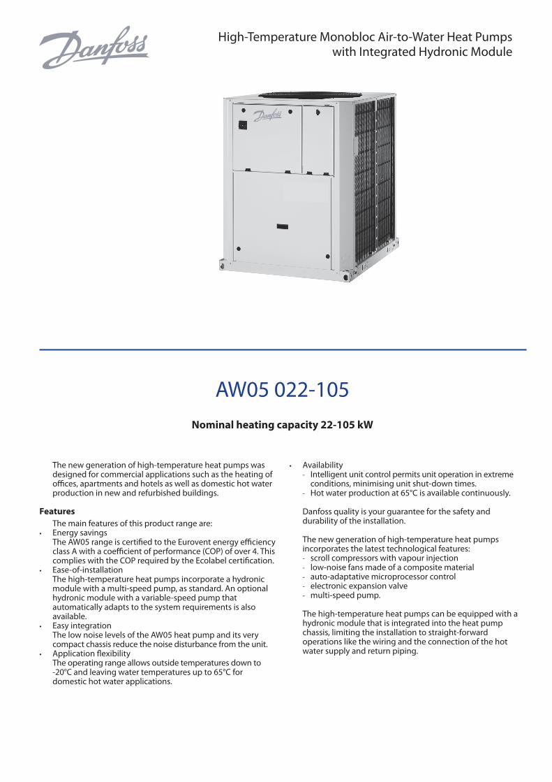
AW05 022-105
Nominal heating capacity 22-105 kW
The new generation of high-temperature heat pumps was designed for commercial applications such as the heating of offices, apartments and hotels as well as domestic hot water production in new and refurbished buildings.
FeaturesThe main features of this product range are:
• Energy savingsThe AW05 range is certified to the Eurovent energy efficiency class A with a coefficient of performance (COP) of over 4. This complies with the COP required by the Ecolabel certification.
• Ease-of-installationThe high-temperature heat pumps incorporate a hydronic module with a multi-speed pump, as standard. An optional hydronic module with a variable-speed pump that automatically adapts to the system requirements is also available.
• Easy integrationThe low noise levels of the AW05 heat pump and its very compact chassis reduce the noise disturbance from the unit.
• Application flexibilityThe operating range allows outside temperatures down to -20°C and leaving water temperatures up to 65°C for domestic hot water applications.
• Availability - Intelligent unit control permits unit operation in extreme
conditions, minimising unit shut-down times. - Hot water production at 65°C is available continuously.
Danfoss quality is your guarantee for the safety and durability of the installation.
The new generation of high-temperature heat pumps incorporates the latest technological features: - scroll compressors with vapour injection - low-noise fans made of a composite material - auto-adaptative microprocessor control - electronic expansion valve - multi-speed pump.
The high-temperature heat pumps can be equipped with a hydronic module that is integrated into the heat pump chassis, limiting the installation to straight-forward operations like the wiring and the connection of the hot water supply and return piping.
High-Temperature Monobloc Air-to-Water Heat Pumpswith Integrated Hydronic Module
Quiet operation • Compressors
- Low-noise scroll compressors with low vibration level. - The compressor assembly is installed on an independent
chassis and supported by anti-vibration mountings. - Dynamic suction and discharge piping supports,
minimising vibration transmission. • Evaporator section
- Vertical evaporator coils - Protection grilles on anti-vibration mountings to protect
the heat exchanger against possible shocks. - Latest-generation low-noise Flying Bird fans, made of a
composite material, are now even quieter and do not generate intrusive low-frequency noise.
- Rigid fan installation for reduced start-up noise.
Easy and fast installation • Integrated hydronic module (option)
- Multi-speed centrifugal water pump, based on the pressure loss of the hydronic installation.
- Water filter protects the water pump against circulating debris.
- Pump protected against cavitation by a pressure transducer that measures the entering water pressure.
- Overpressure valve, set to 4 bar. - Thermal insulation and frost protection down to -20°C,
using an electric resistance heater (see table of options). • Physical features
- The unit has a small footprint and a low height (1329 mm) allowing it to blend in with any architectural styles.
- The unit is enclosed by easily removable panels, covering all components (except condensers and fans).
• Simplified electrical connections - Single power supply point without neutral. - Main disconnect switch with high trip capacity. - Transformer for safe 24 V control circuit supply included.
• Fast commissioning - Systematic factory operation test before shipment. - Quick-test function for step-by-step verification of the
instruments, electrical components and motors.
Economical operation • Increased energy efficiency
- The exceptional energy efficiency level (COP) of the high-temperature heat pumps in the heating mode is the result of a long qualification and optimisation process.
- The electronic expansion device (EXV) allows operation at a lower condensing pressure (COP optimisation).
- Dynamic superheat management for better utilisation of the condenser surface.
• Reduced maintenance costs - Maintenance-free scroll compressors with vapour
injection. - The control system offers fast diagnosis of possible
incidents and their history.
Environmental care • Ozone-friendly R-407C refrigerant
- Chlorine-free refrigerant of the HFC group with zero ozone depletion potential.
- Very efficient - ensures an increased energy efficiency ratio (COP).
• Leak-tight refrigerant circuit - Brazed refrigerant connections for increased leak-
tightness. - Reduction of leaks due to elimination of capillary tubes
(TXVs). - Verification of pressure transducers and temperature
sensors without transferring refrigerant charge.
Superior reliability • State-of-the-art concept
- Cooperation with specialist laboratories and use of limit simulation tools (finite element calculations) for the design of the critical components, e.g. motor supports, suction/discharge piping etc.
• Auto-adaptive control - Control algorithm prevents excessive compressor cycling
and permits reduction of the water quantity in the hydronic circuit.
• Exceptional endurance tests - Corrosion resistance tests in salt mist in the laboratory. - Accelerated ageing test on components that are
submitted to continuous operation: compressor piping, fan supports.
- Transport simulation test in the laboratory on a vibrating table.
2 VDGFG102
Control systemThe control system combines intelligence with operating simplicity. The control constantly monitors all machine parameters and precisely manages the operation of compressors, expansion devices, fans and of the condenser water pump for optimum energy efficiency.
• Energy management - Seven-day internal time schedule clock: permits unit on/
off control and operation at a second set point. - Set point reset based on the outside air temperature or the
return water temperature or on the water heat exchanger delta T.
- Master/slave control of two heat pumps operating in parallel with operating time equalisation and automatic change-over in case of a unit fault (option).
- Start/stop based on the outside air temperature. • Ease-of-use
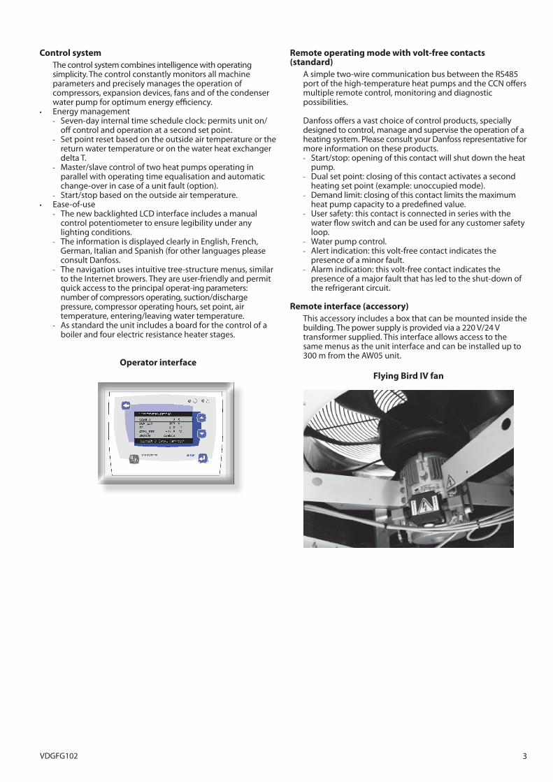
- The new backlighted LCD interface includes a manual control potentiometer to ensure legibility under any lighting conditions.
- The information is displayed clearly in English, French, German, Italian and Spanish (for other languages please consult Danfoss.
- The navigation uses intuitive tree-structure menus, similar to the Internet browers. They are user-friendly and permit quick access to the principal operat-ing parameters: number of compressors operating, suction/discharge pressure, compressor operating hours, set point, air temperature, entering/leaving water temperature.
- As standard the unit includes a board for the control of a boiler and four electric resistance heater stages.
Operator interface
Circuit B Total Capacity
Remote operating mode with volt-free contacts (standard)
A simple two-wire communication bus between the RS485 port of the high-temperature heat pumps and the CCN offers multiple remote control, monitoring and diagnostic possibilities.
Danfoss offers a vast choice of control products, specially designed to control, manage and supervise the operation of a heating system. Please consult your Danfoss representative for more information on these products. - Start/stop: opening of this contact will shut down the heat
pump. - Dual set point: closing of this contact activates a second
heating set point (example: unoccupied mode). - Demand limit: closing of this contact limits the maximum
heat pump capacity to a predefined value. - User safety: this contact is connected in series with the
water flow switch and can be used for any customer safety loop.
- Water pump control. - Alert indication: this volt-free contact indicates the
presence of a minor fault. - Alarm indication: this volt-free contact indicates the
presence of a major fault that has led to the shut-down of the refrigerant circuit.
Remote interface (accessory)This accessory includes a box that can be mounted inside the building. The power supply is provided via a 220 V/24 V transformer supplied. This interface allows access to the same menus as the unit interface and can be installed up to 300 m from the AW05 unit.
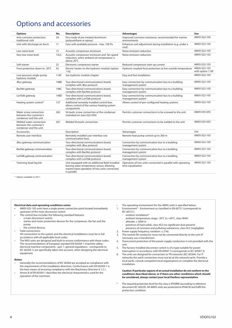
Flying Bird IV fan
3VDGFG102
Options and accessoriesOptions No. Description Advantages UseAnti-corrosion protection, traditional coils
3A Fins made of pre-treated aluminium (polyurethane or epoxy)
Improved corrosion resistance, recommended for marine environments
AW05 022-105
Unit with discharge air ducts 11 Fans with available pressure - max. 100 Pa Enhances unit adjustment during installation (e.g. under a roof )
AW05 022-105
Low noise level 15 Acoustic compressor enclosure Noise emission reduction AW05 022-105
Very low noise level 15LS Acoustic compressor enclosure and fan speed reduction, when ambient air temperature is above 20°C.
Noise emission reduction AW05 022-105
Soft starter 25 Electronic compressor starter Reduced compressor start-up current AW05 022-105
Frost protection down to -20°C 42 Electric heater on the hydronic module (option 116)
Hydronic module frost protection at low outside temperature AW05 022-105with option 116F
Low-pressure single-pump hydronic module
116F See hydronic module chapter Easy and fast installation AW05 022-105
JBus gateway 148B Two-directional communications board, complies with JBus protocol
Easy connection by communication bus to a building management system
AW05 022-105
BacNet gateway 148C Two-directional communications board, complies with BacNet protocol
Easy connection by communication bus to a building management system
AW05 022-105
LonTalk gateway 148D Two-directional communications board, complies with LonTalk protocol
Easy connection by communication bus to a building management system
AW05 022-105
Heating system control* 157 Additional remotely installed control box, allows control of the various heating system components
Allows control of pre-configured heating systems AW05 022-105
Water screw connection between the customer’s condenser and the unit
265 Victaulic screw connection at the condenser (standard on sizes 022-030)
Permits customer connections to be screwed to the unit AW05 035-055
Welded water connection between the customer’s condenser and the unit
267 Welded Victaulic connection Permits customer connections to be welded to the unit AW05 035-055
Accessories Description Advantages Use
Remote user interface Remotely installed user interface (via communication bus).
Remote heat pump control up to 300 m AW05 022-105
JBus gateway communication Two-directional communications board, complies with JBus protocol
Connection by communication bus to a building management system
AW05 022-105
BacNet gateway communication Two-directional communications board, complies with BacNet protocol
Connection by communication bus to a building management system
AW05 022-105
LonTalk gateway communication Two-directional communications board, complies with LonTalk protocol
Connection by communication bus to a building management system
AW05 022-105
Twinning (lead-lag kit) Unit equipped with an additional field-installed leaving water temperature sensor, allowing master/slave operation of two units connected in parallel
Operation of two units connected in parallel with operating time equalisation
AW05 022-105
* Option available in 2011.
Electrical data and operating conditions notes:• AW05 022-105 units have a single power connection point located immediately
upstream of the main disconnect switch.• Thecontrolboxincludesthefollowingstandardfeatures: - a main disconnect switch, - starter and motor protection devices for the compressor, the fan and the
pump, - the control devices.• Fieldconnections: All connections to the system and the electrical installations must be in full
accordance with all applicable local codes.• TheW05unitsaredesignedandbuilttoensureconformancewiththesecodes.
The recommendations of European standard EN 60204-1 (machine safety - electrical machine components - part 1: general regulations - corresponds to IEC 60204-1) are specifically taken into account, when designing the electrical equipment.
Notes: • GenerallytherecommendationsofIEC60364areacceptedascompliancewith
the requirements of the installation directives. Conformance with EN 60204-1 is the best means of ensuring compliance with the Machinery Directive § 1.5.1.
• AnnexBofEN60204‑1describestheelectricalcharacteristicsusedfortheoperation of the machines.
• TheoperatingenvironmentfortheAW05unitsisspecifiedbelow:1. Environment* - Environment as classified in EN 60721 (corresponds to
IEC 60721): - outdoor installation* - ambient temperature range: -20°C to +40°C, class 4K4H - altitude: ≤ 2000 m - presence of hard solids, class 4S2 (no significant dust present) - presence of corrosive and polluting substances, class 4C2 (negligible)2. Power supply frequency variation: ± 2 Hz.3. The neutral (N) conductor must not be connected directly to the unit (if
necessary use a transformer).4. Overcurrent protection of the power supply conductors is not provided with the
unit.5. The factory-installed disconnect switch is of a type suitable for power
interruption in accordance with EN 60947-3 (corresponds to IEC 60947-3)6. The units are designed for connection to TN networks (IEC 60364). For IT
networks the earth connection must not be at the network earth. Provide a local earth, consult competent local organisations to complete the electrical installation.
Caution: If particular aspects of an actual installation do not conform to the conditions described above, or if there are other conditions which should be considered, always contact your local Danfoss representative.
* The required protection level for this class is IP43BW (according to reference document IEC 60529). All AW05 units are protected to IP44CW and fulfil this protection condition.
4 VDGFG102
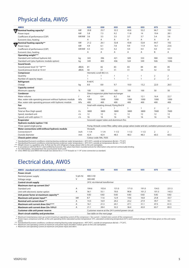
Physical data, AW05AW05 022 030 035 045 055 075 105Nominal heating capacity* kW 20.8 25.7 32.2 43.6 52.2 66.7 102
Power input kW 5.8 7.3 9.2 11.8 14 19.4 28.1
Coefficient of performance (COP) kW/kW 3.6 3.5 3.5 3.7 3.7 3.4 3.6
Eurovent class, heating A A A A A A A
Nominal heating capacity** kW 21.2 26.1 32.8 43.8 52.8 64.7 102
Power input kW 4.9 6.1 7.8 9.9 11.9 16.1 23.6
Coefficient of performance (COP) kW/kW 4.3 4.3 4.2 4.4 4.4 4.0 4.3
Eurovent class, heating A A A A A B AOperating weight***Standard unit (without hydronic kit) kg 343 396 421 509 533 900 1020Standard unit (plus hydronic module option) kg 349 403 436 524 549 926 1046Sound levelsSound power level 10-12 W**** dB(A) 81 82 83 83 84 84 85Sound pressure level at 10 m† dB(A) 50 51 51 51 53 52 53Compressor Hermetic scroll 48.3 r/sQuantity 1 1 1 1 1 2 2Number of capacity stages 1 1 1 1 1 2 2Refrigerant R-407CCharge kg 8.0 8.8 9.7 10.0 13.2 22.0 26.5Capacity controlMinimum capacity % 100 100 100 100 100 50 50Condenser Direct-expansion plate heat exchangerWater volume l 4.9 6.4 8.2 9.6 12.1 16.4 22.7Max. water-side operating pressure without hydronic module kPa 1000 1000 1000 1000 1000 1000 1000Max. water-side operating pressure with hydronic module kPa 400 400 400 400 400 400 400Fan Axial with rotating shroud, Flying Bird IVQuantity 1 1 1 1 1 2 2Total air flow (high speed) l/s 3800 3800 3800 3800 3800 7600 7600Speed, standard unit r/s 12 12 12 12 12 12 12Speed, unit with option 11 r/s 16 16 16 16 16 16 16Evaporator Grooved copper tubes and aluminium finsHydronic module (option 116)Three-speed single pump Pump, Victaulic screen filter, safety valve, purge valves (water and air), cavitation presssure sensorWater connections with/without hydronic module VictaulicConnections†† inch 1-1/4 1-1/4 1-1/2 1-1/2 1-1/2 2 2Outside diameter mm 42.4 42.4 48.3 48.3 48.3 60.3 60.3Chassis paint colour Colour code: RAL 7035
* Standardised Eurovent conditions: entering leaving condenser water temperature = 40°C/45°C, outside air temperature db/wb = 7°C/6°C ** Standardised Eurovent conditions: entering leaving condenser water temperature = 30°C/35°C, outside air temperature db/wb = 7°C/6°C *** Weight shown is a guideline only. To find out the unit refrigerant charge, please refer to the unit nameplate.. **** In accordance with ISO 9614-1 and certified by Eurovent. The values have been rounded and are for information only and not contractually binding † For information, calculated from the sound power level Lw(A) †† Units AW05 022 and AW05 030 include two sleeves for a 1-1/4” Victaulic to 1-1/4” screw connection as standard.
Electrical data, AW05AW05 - standard unit (without hydronic module) 022 030 035 045 055 075 105
Power circuitNominal power supply V-ph-Hz 400-3-50
Voltage range V 360-440
Control circuit supply 24 V, via internal transformer
Maximum start-up current (Un)*Standard unit A 104.6 102.6 131.0 171.0 191.0 154.5 221.5
Unit with electronic starter option A 56.1 55.1 70.0 90.8 101.2 101.5 142.5
Unit power factor at maximum capacity** 0.82 0.82 0.82 0.82 0.82 0.82 0.82
Maximum unit power input** kW 8.7 11.6 12.9 14.6 16.8 25.8 33.7
Nominal unit current draw*** A 14.3 16.9 20.2 23.2 27.9 39.7 55.1
Maximum unit current draw (Un)**** A 16.1 21.3 24.1 27.1 31.1 47.5 61.5
Maximum unit current draw (Un-10%)† A 21.1 28.4 32.2 36.4 42.0 63.7 83.3
Customer-side unit power reserve Customer reserve at the 24 V control power circuitShort-circuit stability and protection See table on the next page
* Maximum instantaneous start-up current (maximum operating current of the compressor + fan current + locked rotor current of the compressor). ** Power input, compressor and fan, at the unit operating limits (saturated suction temperature 10°C, saturated condensing temperature 65°C) and nominal voltage of 400 V (data given on the unit name-
plate). *** Standardised Eurovent conditions: condenser entering/leaving water temperature = 40°C/45°C, outside air temperature db/wb = 7°C/6°C. **** Maximum unit operating current at maximum unit power input and 400 V (values given on the unit nameplate). † Maximum unit operating current at maximum unit power input and 360 V.
5VDGFG102
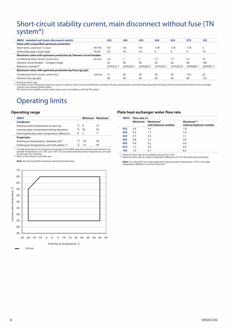
Short-circuit stability current, main disconnect without fuse (TN system*) AW05 - standard unit (main disconnect switch) 022 030 035 045 055 075 105Value with unspecified upstream protectionShort-term current at 1 s (Icw) kA rms 0.6 0.6 0.6 1.26 1.26 1.26 2
Admissible peak current (Ipk) kA pk 4.5 4.5 4.5 6 6 6 10Maximum value with upstream protection by Siemens circuit breakerConditional short-circuit current (Icc) kA rms 5.4 7 7 7.7 7.7 6.1 10Siemens circuit breaker - Compact range 32 40 40 50 63 80 100Reference number** 5SY6332-7 5SY6340-7 5SY6340-7 5SY4350-7 5SY4363-8 5SP4380-7 5SP4391-7Maximum value with upstream protection by fuses (gL/gG)
Conditional short-circuit current (Icc) kA rms 17 50 50 50 50 14.5 22Siemens fuse (gL/gG) 40 40 40 63 63 80 125
* Earthing system type ** If another current limitation protection system is used, its time-current and thermal constraint (I²t) trip characteristics must be at least equivalent to those of the recommended Siemens circuit breaker.
Contact your nearest Danfoss office. The short-circuit stability current values above are in accordance with the TN system.
20
25
30
35
40
45
50
55
60
65
70
-25 -20 -15 -10 -5 0 5 10 15 20 25 30 35 40 45
Entering air temperature, °C
Leav
ing
wat
er te
mp
erat
ure,
°C
Plate heat exchanger water flow rateAW05 Flow rate, l/s
Minimum Maximum*with hydronic module
Maximum**without hydronic module
022 0.4 1.6 1.8030 0.5 1.7 2.4035 0.7 3.3 3.1045 0.8 3.3 3.8055 0.9 3.2 4.6075 1.2 5.9 6.4105 1.6 6.1 8.5
* Maximum flow rate at an available pressure of 15 kPa. ** Maximum flow rate at a water temperature difference of 3 K in the plate heat exchanger.
Note: For a domestic hot water application (leaving water temperature = 65°C), the water temperature difference must be at least 8 K.
Full load
Operating rangeAW05 Minimum MaximumCondenserEntering water temperature at start-up °C 8 57
Leaving water temperature during operation °C 30 65
Entering/leaving water temperature difference K 3 **
EvaporatorEntering air temperature, standard unit* °C -20 40
Entering air temperature, unit with option 11 °C -15 40
* Outside temperature: For transport and storage of the AW05 units the minimum and maximum al-lowable temperatures are -20°C and +50°C. It is recommended that these temperatures are used for transport by container.
** Refer to the minmum unit flow rate.
Note: Do not exceed the maximum operating temperature.
Operating limits
6 VDGFG102
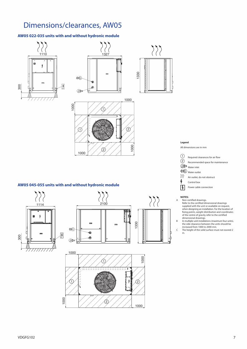
Dimensions/clearances, AW05AW05 022-035 units with and without hydronic module
Legend
All dimensions are in mm
Required clearances for air flow
Recommended space for maintenance
Water inlet
Water outlet
Air outlet, do not obstruct
Control box
Power cable connectionAW05 045-055 units with and without hydronic module
NOTES:A Non-certified drawings. Refer to the certified dimensional drawings
supplied with the unit or available on request, when designing an installation. For the location of fixing points, weight distribution and coordinates of the centre of gravity refer to the certified dimensional drawings.
B In multiple-unit installations (maximum four units), the side clearance between the units should be increased from 1000 to 2000 mm.
C The height of the solid surface must not exceed 2 m.
1000
1000
1000
1000
13271110
1330
300
1114
1000
1000
1000
1000
2100
1330
300
7VDGFG102
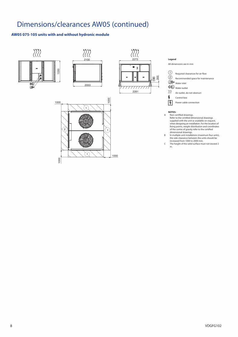
1000
1000
1000
1000
1330
2100
2053
300
2261
2273
1
1
1
2
Dimensions/clearances AW05 (continued)AW05 075-105 units with and without hydronic module
Legend
All dimensions are in mm
Required clearances for air flow
Recommended space for maintenance
Water inlet
Water outlet
Air outlet, do not obstruct
Control box
Power cable connection
NOTES:A Non-certified drawings. Refer to the certified dimensional drawings
supplied with the unit or available on request, when designing an installation. For the location of fixing points, weight distribution and coordinates of the centre of gravity refer to the certified dimensional drawings.
B In multiple-unit installations (maximum four units), the side clearance between the units should be increased from 1000 to 2000 mm.
C The height of the solid surface must not exceed 2 m.
8 VDGFG102
Heating capacities, AW05
Application data Standard units, refrigerant R407CCondenser entering/leaving water temperature difference: 5 K for EWT < 55°CCondenser entering/leaving water temperature difference: 10 K for EWT ≥ 55°CCondenser fluid: waterRelative humidity: 87%Fouling factor: 0 (m2 K)/W - 0.18 x10⁻⁴ (m2 K)/W
Performances in accordance with EN 14511
Outside air temperature, °C-20 -15 -10 -5 0 2 5
AW05 EWT Cap Unit Flow Dp Cap Unit Flow Dp Cap Unit Flow Dp Cap Unit Flow Dp Cap Unit Flow Dp Cap Unit Flow Dp Cap Unit Flow Dp
°C kW kW l/s kPa kW kW l/s kPa kW kW l/s kPa kW kW l/s kPa kW kW l/s kPa kW kW l/s kPa kW kW l/s kPa022 25 10.2 4.80 0.49 1 12.1 4.80 0.58 2 13.9 4.80 0.67 2 15.9 4.80 0.76 3 18.0 4.60 0.87 4 19.0 4.60 0.91 4 20.4 4.60 0.98 5030 10.1 5.70 0.58 1 13.1 5.70 0.58 1 16.0 5.70 0.77 2 19.0 5.80 0.91 3 21.9 5.60 1.05 3 23.2 5.60 1.11 4 25.2 5.70 1.21 4035 15.6 6.60 0.75 1 18.1 6.80 0.87 2 21.0 6.90 1.01 3 24.3 7.00 1.16 3 27.7 6.90 1.33 4 29.2 7.00 1.40 5 31.6 7.00 1.52 5
045 20.0 8.50 0.96 1 24.4 8.70 1.17 3 28.5 9.00 1.37 3 33.1 9.20 1.59 5 38.1 9.10 1.83 6 40.1 9.10 1.93 6 41.3 9.00 1.98 7055 25.6 9.40 1.23 2 29.9 10.0 1.43 3 34.5 10.4 1.66 4 39.8 10.7 1.91 5 45.3 10.8 2.17 6 47.5 10.8 2.28 6 50.3 10.9 2.42 7075 32.0 14.0 1.54 2 37.6 14.4 1.80 3 43.8 14.7 2.10 4 50.7 14.9 2.44 5 58.3 14.7 2.80 7 61.6 14.8 2.96 7 63.1 14.8 3.03 8105 47.6 19.3 2.29 4 54.9 19.9 2.64 5 64.0 20.4 3.08 6 74.1 20.9 3.56 8 85.4 21.2 4.10 11 90.2 21.2 4.33 12 97.6 21.7 4.69 14022 30 9.8 5.20 0.47 1 11.8 5.20 0.57 2 13.9 5.20 0.67 2 15.8 5.20 0.76 3 17.9 4.90 0.86 3 18.8 4.90 0.90 4 20.2 4.90 0.97 4030 10.2 5.90 0.49 1 13.1 6.00 0.62 1 15.9 6.00 0.76 2 18.8 6.10 0.91 3 21.7 6.00 1.04 3 22.9 6.10 1.10 4 24.8 6.10 1.19 4035 15.7 7.10 0.76 1 18.2 7.30 0.87 2 20.9 7.50 1.01 2 24.1 7.60 1.16 3 27.5 7.60 1.32 4 29.0 7.60 1.39 4 31.2 7.70 1.50 5045 18.7 9.10 0.89 1 23.4 9.30 1.12 3 28.2 9.60 1.36 3 32.7 9.80 1.57 4 37.6 9.80 1.81 6 39.6 9.80 1.90 6 41.8 9.80 2.01 7055 25.6 10.0 1.23 2 29.8 10.6 1.43 3 34.4 11.1 1.65 4 39.5 11.5 1.90 5 45.0 11.7 2.16 6 47.2 11.7 2.27 6 50.4 11.8 2.43 7075 31.8 14.9 1.53 2 37.3 15.4 1.79 3 43.4 15.8 2.09 4 50.3 16.1 2.42 5 57.8 16.0 2.78 6 61.0 16.0 2.93 7 63.8 16.1 3.07 8105 47.8 20.6 2.30 3 55.1 21.4 2.65 5 63.9 22.0 3.07 6 73.9 22.6 3.55 8 84.9 22.9 4.09 10 89.7 23.0 4.31 12 97.2 23.4 4.67 13022 35 10.0 5.50 0.48 1 11.9 5.50 0.57 2 13.9 5.50 0.67 2 15.7 5.60 0.76 3 17.8 5.30 0.86 3 18.6 5.30 0.90 4 20.0 5.30 0.96 4030 10.4 6.20 0.50 1 13.2 6.30 0.63 1 15.9 6.40 0.76 2 18.7 6.60 0.90 2 21.5 6.50 1.03 3 22.7 6.50 1.09 4 24.6 6.60 1.18 4035 15.9 7.70 0.77 1 18.3 7.90 0.88 2 21.0 8.10 1.01 2 24.0 8.30 1.16 3 27.4 8.20 1.32 4 28.8 8.30 1.39 4 30.9 8.40 1.49 5045 18.7 9.60 0.89 1 23.3 9.90 1.11 3 28.0 10.2 1.35 3 32.3 10.5 1.56 4 37.2 10.6 1.79 5 39.1 10.6 1.88 6 42.1 10.7 2.03 7055 25.7 10.6 1.24 2 29.8 11.3 1.44 3 34.3 11.9 1.65 3 39.3 12.3 1.89 4 44.7 12.6 2.16 6 46.9 12.6 2.26 6 50.2 12.8 2.42 7075 31.7 15.9 1.53 2 37.1 16.4 1.79 3 43.2 16.9 2.08 4 49.9 17.4 2.41 5 57.3 17.3 2.76 6 60.5 17.5 2.91 7 64.7 17.6 3.12 8105 48.1 22.0 2.32 3 55.4 23.0 2.67 5 64.0 23.8 3.08 6 73.8 24.5 3.56 8 84.7 24.9 4.08 10 89.4 25.0 4.31 11 96.8 25.4 4.66 13022 40 10.1 5.90 0.48 1 12.0 5.90 0.58 2 14.0 6.00 0.67 2 15.8 6.00 0.76 3 17.7 5.80 0.86 3 18.6 5.80 0.90 4 19.9 5.80 0.96 4030 9.5 6.60 0.45 1 12.5 6.70 0.60 1 15.4 6.90 0.74 2 18.4 7.20 0.88 2 21.4 7.10 1.03 3 22.5 7.10 1.09 3 24.4 7.20 1.18 4035 16.1 8.30 0.78 1 18.5 8.60 0.89 2 21.1 8.80 1.02 2 24.0 9.00 1.16 3 27.3 9.00 1.32 4 28.6 9.00 1.38 4 30.7 9.10 1.48 5045 19.1 10.3 0.91 1 23.5 10.6 1.12 3 27.9 11.0 1.35 3 32.1 11.3 1.55 4 36.7 11.5 1.77 5 38.7 11.5 1.87 6 41.7 11.7 2.01 6055 25.9 11.5 1.25 2 30.0 12.2 1.45 3 34.4 12.8 1.66 3 39.2 13.3 1.89 4 44.6 13.6 2.15 5 46.7 13.6 2.25 6 50.0 13.9 2.41 7075 31.7 17.0 1.53 2 37.1 17.6 1.79 3 43.0 18.2 2.08 4 49.7 18.8 2.40 5 57.0 18.8 2.75 6 60.1 19.0 2.90 7 65.0 19.3 3.13 8105 48.5 23.5 2.34 3 55.9 24.7 2.70 5 64.4 25.8 3.11 6 74.0 26.7 3.57 8 84.8 27.1 4.09 10 89.4 27.3 4.31 11 96.6 27.8 4.66 13022 45 10.4 6.30 0.50 1 12.2 6.40 0.58 2 14.1 6.50 0.68 2 15.9 6.50 0.77 3 17.8 6.40 0.86 3 18.6 6.40 0.90 4 19.9 6.40 0.96 4030 9.3 7.10 0.44 1 12.3 7.30 0.59 1 15.3 7.40 0.73 2 18.3 7.80 0.88 2 21.4 7.70 1.03 3 22.5 7.80 1.09 3 24.3 7.90 1.17 4035 15.9 9.00 0.76 1 18.7 9.30 0.90 2 21.2 9.50 1.03 2 24.1 9.70 1.16 3 27.2 9.70 1.32 4 28.6 9.80 1.38 4 30.6 10.0 1.48 5045 17.0 11.1 0.81 1 21.8 11.5 1.04 3 28.0 11.9 1.35 3 32.0 12.3 1.55 4 36.5 12.4 1.76 5 38.4 12.6 1.86 5 41.3 12.7 2.00 6055 25.8 12.7 1.23 2 30.4 13.3 1.47 3 34.7 13.9 1.67 3 39.3 14.3 1.90 4 44.5 14.7 2.15 5 46.7 14.8 2.26 6 49.8 15.0 2.41 6075 31.8 18.1 1.54 2 37.1 18.9 1.79 3 43.1 19.7 2.08 4 49.6 20.3 2.40 5 56.8 20.5 2.75 6 59.9 20.7 2.89 7 64.7 21.1 3.13 8105 49.0 25.0 2.37 3 56.6 26.6 2.73 5 64.9 27.9 3.14 6 74.5 29.0 3.60 8 85.0 29.7 4.11 10 89.6 29.9 4.33 11 96.8 30.4 4.67 13022 50 10.7 6.80 0.51 1 12.5 6.90 0.60 2 14.3 7.00 0.69 2 16.1 7.10 0.78 3 18.0 7.00 0.87 3 18.7 7.00 0.91 4 19.9 7.00 0.97 4030 10.5 7.60 0.50 1 13.2 7.90 0.63 1 16.0 8.10 0.76 2 18.8 8.50 0.90 2 21.5 8.50 1.04 3 22.6 8.60 1.09 3 24.3 8.70 1.18 4035 16.3 9.70 0.78 1 18.9 10.0 0.92 2 21.4 10.3 1.04 2 24.2 10.5 1.17 3 27.2 10.6 1.32 4 28.6 10.7 1.38 4 30.5 10.9 1.48 4045 18.9 12.1 0.90 1 23.3 12.5 1.11 3 27.7 12.8 1.32 3 32.1 13.3 1.55 4 36.4 13.6 1.76 5 38.2 13.7 1.85 5 41.1 13.9 1.99 6055 26.6 14.1 1.27 2 31.0 14.6 1.50 3 35.1 15.2 1.70 3 39.6 15.6 1.92 4 44.6 16.0 2.16 5 46.7 16.1 2.26 6 49.8 16.4 2.41 6075 32.0 19.4 1.55 2 37.3 20.4 1.81 3 43.2 21.2 2.09 4 49.7 22.0 2.41 5 56.8 22.3 2.75 6 59.8 22.6 2.90 6 64.6 23.0 3.13 7105 49.7 26.7 2.41 3 57.5 28.7 2.78 5 65.7 30.3 3.18 6 75.3 31.7 3.65 8 85.7 32.6 4.15 10 90.1 32.9 4.36 11 97.2 33.5 4.71 12022 55 - - - - - - - - 14.9 8.30 0.36 1 16.7 8.50 0.41 1 18.5 8.40 0.45 1 19.2 8.50 0.47 1 20.4 8.50 0.49 1030 - - - - - - - - 16.6 9.60 0.40 1 19.2 10.2 0.46 1 21.9 10.2 0.52 1 23.0 10.3 0.56 1 24.6 10.5 0.60 1035 - - - - - - - - 20.9 12.1 0.50 1 24.1 12.4 0.58 1 27.3 12.4 0.65 1 28.6 12.5 0.70 1 30.6 12.7 0.74 1045 - - - - - - - - 28.7 15.3 0.68 1 32.7 15.9 0.79 1 36.6 16.1 0.89 1 38.4 16.3 0.93 1 41.1 16.6 1.00 2055 - - - - - - - - 36.6 18.4 0.89 1 40.2 18.7 0.96 1 45.2 19.1 1.08 1 47.2 19.2 1.15 2 50.3 19.5 1.22 2075 - - - - - - - - 43.9 24.3 1.07 1 50.3 25.2 1.22 1 57.2 25.7 1.39 2 60.2 26.0 1.46 2 64.8 26.5 1.57 2105 - - - - - - - - 67.7 34.6 1.64 2 77.2 36.4 1.87 2 87.5 37.5 2.12 3 91.9 37.9 2.23 3 98.6 38.6 2.39 3
Legend EWT Entering water temperatureCap kW Heating capacity Unit kW Unit power input Flow l/s Condenser water flow rateDp kPa Condenser pressure drop
9VDGFG102
Heating capacities, AW05Outside air temperature, °C7 10 15 20 25 30 35
AW05 EWT Cap Unit Flow Dp Cap Unit Flow Dp Cap Unit Flow Dp Cap Unit Flow Dp Cap Unit Flow Dp Cap Unit Flow Dp Cap Unit Flow Dp
°C kW kW l/s kPa kW kW l/s kPa kW kW l/s kPa kW kW l/s kPa kW kW l/s kPa kW kW l/s kPa kW kW l/s kPa022 25 21.5 4.60 1.03 5 23.0 4.60 1.11 6 23.2 4.60 1.11 6 23.2 4.60 1.11 6 23.2 4.50 1.11 6 23.2 4.50 1.11 6 23.2 4.50 1.11 6030 26.5 5.70 1.27 5 28.6 5.70 1.37 6 32.1 5.70 1.54 7 35.3 5.60 1.70 8 38.7 5.90 1.85 10 42.1 5.70 2.01 12 42.1 5.70 2.01 12035 33.3 7.10 1.60 6 36.0 7.20 1.73 7 40.4 7.30 1.94 8 38.2 7.40 1.83 7 39.6 7.50 1.89 8 41.8 7.60 2.00 9 41.8 7.60 2.00 9
045 42.8 9.10 2.04 7 44.6 9.10 2.13 8 47.8 9.20 2.28 9 50.9 9.30 2.43 10 54.0 9.40 2.58 11 57.1 9.50 2.73 13 57.1 9.50 2.73 13055 51.4 10.9 2.47 7 52.4 10.9 2.50 8 55.1 11.0 2.63 8 58.9 11.1 2.81 10 62.7 11.2 2.99 11 66.5 11.3 3.18 12 66.5 11.3 3.18 12075 64.1 14.8 3.08 8 66.2 14.8 3.18 9 69.7 14.8 3.35 9 73.3 14.9 3.52 10 76.9 14.9 3.70 11 80.6 14.9 3.87 12 84.3 14.9 4.05 13105 102 21.9 4.90 15 109 22.3 5.23 17 121 23.2 5.81 21 123 23.3 5.92 22 126 23.4 6.03 22 128 23.6 6.14 23 130 23.7 6.25 24022 30 21.2 4.90 1.02 5 22.8 4.90 1.09 5 23.5 4.90 1.13 6 23.5 4.90 1.13 6 23.5 4.90 1.13 6 23.5 4.90 1.13 6 23.5 4.90 1.13 6030 26.1 6.10 1.26 5 28.1 6.10 1.35 5 31.7 6.20 1.53 7 34.9 6.20 1.68 8 38.4 6.40 1.84 10 41.8 6.50 2.00 11 41.8 6.50 2.00 11035 32.8 7.70 1.58 6 35.4 7.80 1.70 6 39.8 8.00 1.92 8 42.9 8.10 2.05 9 46.2 8.30 2.21 10 50.4 8.40 2.41 12 50.4 8.40 2.41 12045 43.6 9.90 2.08 7 46.1 9.90 2.20 8 50.2 10.1 2.40 10 54.4 10.2 2.60 11 58.6 10.3 2.80 13 62.8 10.4 3.00 15 62.8 10.4 3.00 15055 51.9 11.9 2.49 7 53.2 12.0 2.54 8 56.7 12.2 2.71 9 61.2 12.3 2.92 10 65.7 12.5 3.14 12 70.2 12.7 3.35 13 70.2 12.7 3.35 13075 64.7 16.1 3.11 8 66.7 16.2 3.21 8 70.1 16.2 3.37 9 73.7 16.3 3.55 10 77.3 16.3 3.72 11 81.0 16.4 3.90 12 84.7 16.4 4.07 13105 102 23.6 4.89 15 108 24.0 5.20 16 120 24.8 5.76 20 124 25.1 5.99 21 127 25.2 6.10 22 129 25.3 6.21 23 131 25.5 6.32 24022 35 20.9 5.30 1.01 5 22.5 5.40 1.08 5 23.9 5.40 1.15 6 23.9 5.30 1.15 6 23.9 5.30 1.15 6 23.9 5.30 1.15 6 23.9 5.30 1.15 6030 25.9 6.70 1.25 4 27.8 6.70 1.34 5 31.3 6.80 1.51 6 34.6 6.80 1.67 8 38.1 7.10 1.82 9 41.5 7.20 1.98 11 41.5 7.20 1.98 11035 32.5 8.50 1.56 5 35.0 8.60 1.68 6 39.3 8.70 1.90 7 42.3 8.90 2.02 8 45.5 9.10 2.17 10 49.6 9.20 2.37 12 49.6 9.20 2.37 12045 44.1 10.8 2.11 7 47.0 10.8 2.25 8 52.0 11.0 2.48 10 56.9 11.1 2.72 12 61.9 11.2 2.96 14 66.9 11.3 3.19 17 66.9 11.3 3.19 17055 52.0 12.9 2.51 7 53.5 13.1 2.56 8 57.3 13.3 2.74 9 62.2 13.6 2.97 10 67.1 13.8 3.21 12 72.0 14.1 3.44 14 72.0 14.1 3.44 14075 65.6 17.7 3.16 8 67.3 17.7 3.24 8 70.8 17.8 3.41 9 74.3 17.9 3.58 10 77.8 18.0 3.75 11 81.5 18.0 3.93 12 85.2 18.1 4.10 13105 102 25.7 4.90 14 108 26.1 5.20 16 119 26.8 5.73 19 126 27.3 6.07 21 128 27.4 6.18 22 130 27.5 6.29 23 133 27.6 6.40 24022 40 20.8 5.80 1.00 4 22.3 5.80 1.07 5 24.4 5.80 1.18 6 24.4 5.80 1.18 6 24.4 5.80 1.18 6 24.4 5.80 1.18 6 24.4 5.80 1.18 6030 25.7 7.30 1.24 4 27.6 7.30 1.33 5 30.9 7.40 1.49 6 34.4 7.50 1.66 7 37.8 7.80 1.81 9 41.2 8.00 1.97 11 41.2 8.00 1.97 11035 32.2 9.20 1.55 5 34.6 9.30 1.67 6 38.9 9.50 1.88 7 41.8 9.70 2.00 8 45.0 9.90 2.15 9 49.0 10.1 2.34 11 49.0 10.1 2.34 11045 43.6 11.8 2.08 7 46.6 11.9 2.22 8 51.5 12.1 2.46 10 56.4 12.3 2.69 12 61.3 12.5 2.93 14 66.2 12.7 3.16 16 66.2 12.7 3.16 16055 52.2 14.0 2.52 7 53.8 14.2 2.57 8 58.0 14.5 2.77 9 63.2 14.9 3.02 10 68.4 15.2 3.27 12 73.7 15.6 3.52 14 73.7 15.6 3.52 14075 66.7 19.4 3.22 8 68.1 19.4 3.28 8 71.6 19.5 3.45 9 75.1 19.7 3.62 10 78.6 19.8 3.79 11 82.2 19.9 3.97 12 85.9 20.0 4.14 13105 102 28.1 4.90 14 108 28.5 5.22 16 119 29.2 5.74 19 128 29.8 6.17 22 130 30.0 6.27 22 132 30.1 6.38 23 135 30.2 6.49 24022 45 20.8 6.40 1.00 4 22.1 6.40 1.07 5 24.7 6.40 1.19 6 24.9 6.40 1.21 6 24.9 6.40 1.21 6 24.9 6.40 1.21 6 24.9 6.40 1.21 6030 25.5 8.00 1.23 4 27.4 8.10 1.33 5 30.7 8.20 1.49 6 34.3 8.40 1.66 7 37.6 8.70 1.80 9 41.1 8.90 1.96 10 41.1 8.90 1.96 10035 32.0 10.1 1.55 5 34.3 10.2 1.66 6 38.5 10.4 1.86 7 41.2 10.6 1.97 8 44.2 10.9 2.11 9 48.1 11.1 2.30 11 48.1 11.1 2.30 11045 43.3 12.8 2.07 7 46.2 13.0 2.21 8 51.1 13.3 2.44 9 55.9 13.6 2.67 11 60.8 13.9 2.90 13 65.6 14.1 3.14 15 65.6 14.1 3.14 15055 52.0 15.2 2.51 7 53.6 15.4 2.56 7 57.5 15.8 2.75 8 62.6 16.2 2.99 10 67.7 16.6 3.23 12 72.8 16.9 3.48 13 72.8 16.9 3.48 13075 67.8 21.3 3.28 8 69.3 21.3 3.35 9 72.5 21.5 3.50 9 76.1 21.7 3.68 10 79.6 21.8 3.85 11 83.2 22.0 4.02 12 86.9 22.1 4.20 13105 102 30.8 4.92 14 109 31.3 5.25 16 120 32.1 5.77 19 130 32.8 6.29 22 132 33.0 6.40 23 135 33.1 6.51 23 137 33.3 6.62 24022 50 20.8 7.10 1.01 4 22.1 7.10 1.07 5 24.5 7.10 1.19 6 25.6 7.10 1.24 6 25.6 7.10 1.24 6 25.6 7.10 1.24 6 25.6 7.00 1.24 6030 25.5 8.80 1.23 4 27.4 8.90 1.33 5 30.6 9.10 1.48 6 34.1 9.30 1.65 7 37.3 9.60 1.78 8 40.7 9.90 1.94 10 40.7 9.90 1.94 10035 31.9 11.0 1.55 5 34.1 11.1 1.65 5 38.1 11.4 1.84 7 40.6 11.6 1.94 7 43.5 11.8 2.08 8 47.1 12.1 2.25 10 47.1 12.1 2.25 10045 43.1 14.1 2.06 6 45.9 14.3 2.19 7 50.7 14.6 2.42 9 55.5 15.0 2.65 11 60.3 15.3 2.88 13 65.0 15.7 3.11 15 65.0 15.7 3.11 15055 51.9 16.5 2.52 7 53.4 16.8 2.55 7 57.2 17.2 2.74 8 62.2 17.6 2.97 10 67.1 18.0 3.21 11 72.1 18.4 3.44 13 72.1 18.4 3.44 13075 67.9 23.3 3.29 8 70.8 23.5 3.43 9 73.7 23.7 3.57 9 77.3 23.9 3.74 10 80.9 24.2 3.91 11 84.5 24.4 4.09 12 88.1 24.6 4.27 13105 102 33.9 4.94 14 110 34.5 5.31 16 120 35.4 5.82 19 132 36.3 6.37 22 135 36.5 6.55 23 138 36.7 6.66 24 140 36.9 6.77 25022 55 21.1 8.60 0.51 1 22.4 8.60 0.54 1 24.5 8.70 0.60 2 26.9 8.70 0.65 2 27.1 8.70 0.66 2 27.1 8.70 0.66 2 27.1 8.70 0.66 2030 25.7 10.6 0.62 1 27.4 10.8 0.67 1 30.6 11.1 0.74 2 33.8 11.3 0.82 2 37.0 11.7 0.88 2 40.2 12.0 0.96 3 40.2 12.0 0.96 3035 31.8 12.9 0.77 1 33.9 13.0 0.82 2 37.4 13.3 0.91 2 39.7 13.6 0.95 2 42.2 14.0 1.01 2 45.5 14.3 1.09 3 45.5 14.3 1.09 3045 42.8 16.8 1.02 2 45.5 17.0 1.09 2 49.9 17.5 1.19 2 54.3 17.9 1.30 3 58.7 18.4 1.40 3 63.1 18.8 1.51 4 63.1 18.8 1.51 4055 52.3 19.6 1.27 2 53.6 19.9 1.28 2 57.3 20.3 1.37 2 62.1 20.7 1.48 3 66.9 21.1 1.60 3 71.6 21.5 1.71 3 71.6 21.5 1.71 3075 68.0 26.8 1.65 2 73.1 27.2 1.77 2 75.8 27.4 1.84 3 79.4 27.6 1.93 3 83.0 27.9 2.01 3 86.6 28.1 2.10 3 90.2 28.3 2.19 4105 103 39.1 2.51 4 111 39.6 2.69 4 122 40.4 2.96 5 133 41.2 3.23 6 139 41.6 3.38 6 142 41.7 3.44 7 144 41.8 3.49 7
Legend EWT Entering water temperatureCap kW Heating capacity Unit kW Unit power input Flow l/s Condenser water flow rateDp kPa Condenser pressure drop
Application data Standard units, refrigerant R407CCondenser entering/leaving water temperature difference: 5 K for EWT < 55°CCondenser entering/leaving water temperature difference: 10 K for EWT ≥ 55°CCondenser fluid: waterRelative humidity: 87%Fouling factor: 0 (m2 K)/W - 0.18 x10⁻⁴ (m2 K)/W
Performances in accordance with EN 14511
10 VDGFG102
Hydronic module (option 116)Typical hydronic circuit diagramThe hydronic module option reduces the installation time.
The heat pump is factory-equipped with the main hydronic components required for the installation: screen filter, water pump, safety valve, water pressure transducer, flow switch. The control system allows integration of system and water pump protection devices (insufficient water flow rate, water pressure, water flow rate etc.).
The pump supplied with the hydronic module is a multi-speed pump.
An automatic pump start-up algorithm protects the heat exchanger and the hydronic module piping against frost down to -10°C outside air temperature, as standard. If necessary, increased frost protection down to -20 °C is possible by adding heaters to the hydronic module piping (see option 42).
The hydronic module option is integrated into the heat pump without increasing its dimensions and saves the space normally used for the water pump.
Legend
Components of the unit and hydronic module1 Victaulic screen filter2 Pressure sensor Note: Gives pump suction pressure information (see installation manual)3 Safety valve4 Water drain valve 5 Shut-off valve6 Water pump7 Temperature sensors, BPHE inlet Note: Gives heat exchanger entering temperature information (see installation manual)8 Pressure gauge Note: Allows measuring of the pump suction pressure, the pump leaving pressure and the heat
exchanger leaving pressure9 Temperature sensor, BPHE outlet Note: Gives heat exchanger leaving temperature information (see installation manual)10 Automatic air vent 11 Flow switch12 Plate heat exchanger frost protection heater13 Plate heat exchanger
Installation components14 Temperature probe well15 Air vent16 Flexible connection17 Shut-off valve18 Screen filter (obligatory for a unit without hydronic module)19 Pressure gauge20 Water flow control valve21 Charge valve22 Frost protection bypass valve (when shut-off valves [17] are closed during winter)
--- Hydronic module (unit with hydronic module)
Notes: • Unitswithouthydronicmodule(standardunits)areequippedwithaflowswitchandtwotem-
perature sensors (7 and 9). • Forunitsequippedwithhydronicmodule,thepressuresensorlocatedupstreamofthepumpto
prevent cavitation is installed on a connection without Schraeder valves. Depressurise and drain the system before any intervention.
Physical and electrical data, units with hydronic module AW05 022 030 035 045 055 075 105Operating weight*Unit with hydronic module kg 349 403 436 524 549 926 1044Hydronic moduleMaximum operating pressure kPa 400 400 400 400 400 400 400Water filter Victaulic screen filterPumpsWater pump TOP-S 25 TOP-S 25 TOP-S40 TOP-S40 TOP-S40 TOP-S50 TOP-S50Shaft power input kW 0.18 0.18 0.35 0.35 0.35 0.45 0.45Power input** kW 0.42 0.42 0.63 0.63 0.63 0.95 0.95Nominal operating current draw A 0.4 0.4 0.6 0.6 0.7 1.3 1.5Maximum current draw at 400 V*** A 0.8 0.8 1.3 1.3 1.3 1.7 1.7Water connections (with hydronic module)Connections inch 1-1/4 1-1/4 1-1/2 1-1/2 1-1/2 2 2Outside diameter mm 42.4 42.4 48.3 48.3 48.3 60.3 60.3
* Weight shown is a guideline only. To find out the unit refrigerant charge, please refer to the unit nameplate. ** To obtain the maximum power input for a unit with hydronic module, add the maximum unit power input to the pump power input. *** To obtain the maximum operating current draw for a unit with hydronic module, add the maximum unit current draw to the pump current draw.
1
21
19
19
22
17
17
14
14
15
16
16
20
18
11 109
23 6
75
12
4
8
4
5
5
134
Hydronic module
11VDGFG102
Units with fans with available pressure for indoor installation (option 11)This option applies to AW05 units installed inside the building in a plant room. For this type of installation the cold air leaving the air-cooled evaporators is discharged by the fans to the outside of the building, using a duct system.
The installation of a duct system at the air evaporator discharge line causes a pressure drop due to the resistance caused by the air flow.
Therefore more powerful fan motors than those used for the standard units are installed in the units with this option. For each installation of a unit installed inside a plant room the duct pressure drops differ, depending on the duct length, duct section and direction changes. AW05 units equipped with fans with available pressure are designed to operate with air discharge ducts with maximum pressure drops of 100 Pa.
Fan discharge connection A square flange is supplied mounted on the unit. An available standard round flange can easily be installed at the fan discharge, if the installer prefers the use of a round connection duct.
The unit is supplied with a grille on the discharge side. This grille has to be removed before connection to the duct system.
It is advisable to make the connection to the duct system with a flexible sleeve. If this recommendation is not observed, a lot of vibration and noise may be transmitted to the building structure.
Applicable rules for units incorporated into an air duct system
Ensure that the suction or discharge inlets are not accident-ally obstructed by the panel positioning (e.g. low return or open doors etc.).
Electrical data for AW05 units with option 11
AW05 - units with option 11 (without hydronic kit)
022 030 035 045 055 075 105
Power circuitNominal power supply V-ph-Hz 400-3-50Voltage range V 360-440Control circuit supply 24 V, via internal transformerMaximum start-up current (Un)*Standard unit A 107,1 105,1 133,5 173,5 193,5 159,5 226,5Unit with electronic starter option A 58,6 57,6 72,5 93,3 103,7 106,5 147,5Unit power factor at maximum capacity** 0,82 0,82 0,82 0,82 0,82 0,82 0,82Maximum unit power input** kW 9,8 12,7 14 15,7 17,9 28 35,9Nominal unit current draw*** A 16,4 19 22,3 25,3 30 43,9 59,3Maximum unit current draw (Un)**** A 18,5 23,7 26,5 29,5 33,5 52,3 66,3Maximum unit current draw (Un-10%)† A 23,2 30,5 34,3 38,5 44,1 67,9 87,5Customer-side unit power reserve Customer reserve at the 24 V control power circuitShort-circuit stability and protection See table on the next page
* Maximum instantaneous start-up current (maximum operating current of the compressor + fan current + locked rotor current of the compressor). ** Power input, compressor and fan, at the unit operating limits (saturated suction temperature 10°C, saturated condensing temperature 65°C) and nominal voltage of 400 V (data given on the unit name-
plate). *** Standardised Eurovent conditions: condenser entering/leaving water temperature = 40°C/45°C, outside air temperature db/wb = 7°C/6°C. **** Maximum unit operating current at maximum unit power input and 400 V (values given on the unit nameplate). † Maximum unit operating current at maximum unit power input and 360 V.
12 VDGFG102
Dimensions/clearances, AW05 units with option 11AW05 022-035 units with and without hydronic module
Legend
All dimensions are in mm
Required clearances for air flow
Recommended space for maintenance
Water inlet
Water outlet
Air outlet, do not obstruct
Control box
Power cable connection
NOTES:A Non-certified drawings. Refer to the certified dimensional drawings supplied with the unit or available on request, when
designing an installation. For the location of fixing points, weight distribution and coordinates of the centre of gravity refer to the certified dimensional drawings.
B In multiple-unit installations (maximum four units), the side clearance between the units should be increased from 1000 to 2000 mm.
C The height of the solid surface must not exceed 2 m.
1110
300
1280
1327
1371
2
2
1
1
1000
1000
1000
1000
13VDGFG102
Dimensions/clearances, AW05 units with option 11 (continued)AW05 045-055 units with and without hydronic module
NOTES:A Non-certified drawings. Refer to the certified dimensional drawings supplied with the unit or available on request, when
designing an installation. For the location of fixing points, weight distribution and coordinates of the centre of gravity refer to the certified dimensional drawings.
B In multiple-unit installations (maximum four units), the side clearance between the units should be increased from 1000 to 2000 mm.
C The height of the solid surface must not exceed 2 m.
1114
300
1000
1000
1000
1000
2079
1371
1
1
2
2
Legend
All dimensions are in mm
Required clearances for air flow
Recommended space for maintenance
Water inlet
Water outlet
Air outlet, do not obstruct
Control box
Power cable connection
14 VDGFG102
Dimensions/clearances, AW05 units with option 11 (continued)AW05 075-105 units with and without hydronic module
NOTES:A Non-certified drawings. Refer to the certified dimensional drawings supplied with the unit or available on request, when
designing an installation. For the location of fixing points, weight distribution and coordinates of the centre of gravity refer to the certified dimensional drawings.
B In multiple-unit installations (maximum four units), the side clearance between the units should be increased from 1000 to 2000 mm.
C The height of the solid surface must not exceed 2 m.
1371
2100 2273
300
1000
1000
1000
1000
1
1 2
2
Legend
All dimensions are in mm
Required clearances for air flow
Recommended space for maintenance
Water inlet
Water outlet
Air outlet, do not obstruct
Control box
Power cable connection
15VDGFG102
Available static system pressurePlate heat exchanger pressure drop - for pure water at 20°C
Water flow rate, l/s
Pres
sure
dro
p, k
Pa
1 AW05 022 2 AW05 030 3 AW05 035 4 AW05 045
AW05 022-045
0
5
10
15
20
25
30
0 1 2 3 4 5
12
34
0
10
20
30
40
50
0 2 4 6 8 10
1
2
3
Water flow rate, l/sPr
essu
re d
rop,
kPa
AW05 055-105
1 AW05 055 2 AW05 075 3 AW05 105
16 VDGFG102
Water flow rate, l/s
Pres
ssur
e he
ad, k
Pa
1 AW05 022-030 (speed 1) 2 AW05 022-030 (speed 2): selected 3 AW05 022-030 (speed 3)
Water flow rate, l/s
Pres
ssur
e he
ad, k
Pa
1 AW05 035-055 (speed 1) 2 AW05 035-055 (speed 2): selected 3 AW05 035-055 (speed 3)
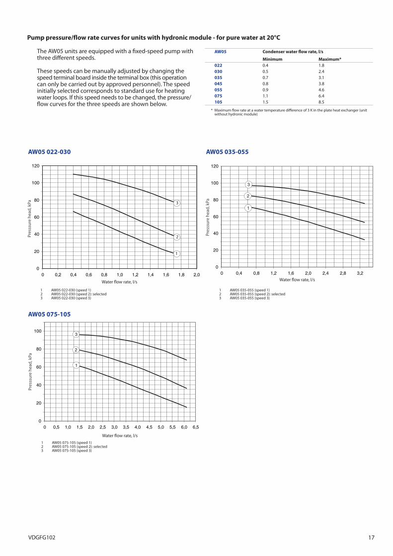
AW05 Condenser water flow rate, l/s
Minimum Maximum*022 0.4 1.8030 0.5 2.4035 0.7 3.1045 0.8 3.8055 0.9 4.6075 1.1 6.4105 1.5 8.5
* Maximum flow rate at a water temperature difference of 3 K in the plate heat exchanger (unit without hydronic module)
The AW05 units are equipped with a fixed-speed pump with three different speeds.
These speeds can be manually adjusted by changing the speed terminal board inside the terminal box (this operation can only be carried out by approved personnel). The speed initially selected corresponds to standard use for heating water loops. If this speed needs to be changed, the pressure/flow curves for the three speeds are shown below.
AW05 022-030 AW05 035-055
Pump pressure/flow rate curves for units with hydronic module - for pure water at 20°C
0
20
40
60
80
100
0 0,5 1,0 1,5 2,0 2,5 3,0 3,5 4,0 4,5 5,0 5,5 6,0 6,5
1
2
3
0
20
40
60
80
100
120
0 0,2 0,4 0,6 0,8 1,0 1,2 1,4 1,6 1,8 2,0
1
1
2
3
0
20
40
60
80
100
120
0 0,4 0,8 1,2 1,6 2,0 2,4 2,8 3,2
1
2
3
AW05 075-105
Water flow rate, l/s
Pres
ssur
e he
ad, k
Pa
1 AW05 075-105 (speed 1) 2 AW05 075-105 (speed 2): selected 3 AW05 075-105 (speed 3)
17VDGFG102
0
20
40
60
80
100
0,5 1,0 1,5 2,0 2,5 3,0 3,5
3
21
0
10
20
30
40
50
60
70
80
90
100
0,4 0,6 0,8 1,0 1,2 1,4 1,6 1,8
21
Water flow rate, l/s
Ava
ilab
le p
ress
ure,
kPa
Water flow rate, l/s
1 AW05 035 2 AW05 045 3 AW05 055
Ava
ilab
le p
ress
ure,
kPa
1 AW05 022 2 AW05 030
Available static system pressure (cont.)Available system pressure for units with hydronic module - for pure water at 20°C
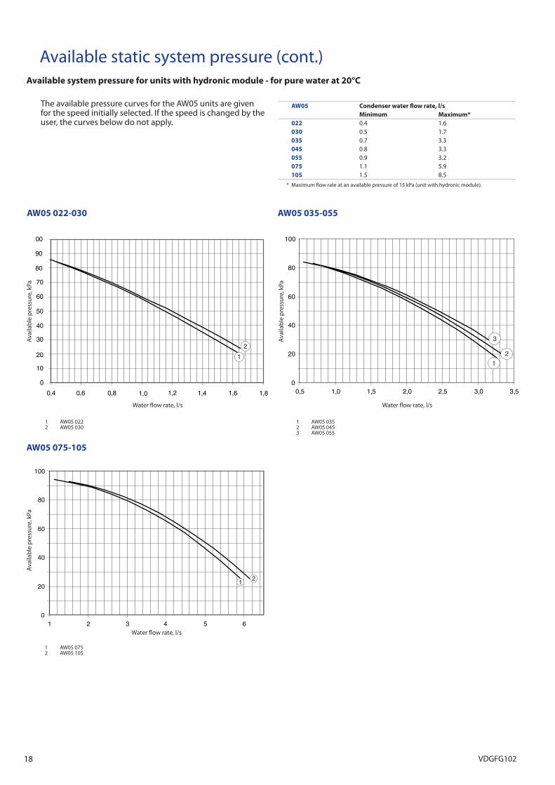
The available pressure curves for the AW05 units are given for the speed initially selected. If the speed is changed by the user, the curves below do not apply.
AW05 022-030 AW05 035-055
0
20
40
60
80
100
1 2 3 4 5 6
1 2
AW05 Condenser water flow rate, l/sMinimum Maximum*
022 0.4 1.6030 0.5 1.7035 0.7 3.3045 0.8 3.3055 0.9 3.2075 1.1 5.9105 1.5 8.5
* Maximum flow rate at an available pressure of 15 kPa (unit with hydronic module).
Water flow rate, l/s
Ava
ilab
le p
ress
ure,
kPa
1 AW05 075 2 AW05 105
AW05 075-105
18 VDGFG102

VDGFG102