awd power buggy - southern tool and parts manual awd power buggy model wbh-16eawd (electric start)...
TRANSCRIPT

OPERATION AND PARTS MANUAL
AWD POWER BUGGYMODEL WBH-16EAWD
(ELECTRIC START)
Revision #5 (01/05/07)
THIS MANUAL MUST ACCOMPANY THE EQUIPMENT AT ALL TIMES.
To find the latest revision of thispublication, visit our website at:
www.multiquip.com

Engine exhaust and some ofits constituents, and some dust created
of California to cause cancer, birthdefects and other reproductive harm.
by power sanding, sawing, grinding,drillingandotherconstructionactivitiescontains chemicals known to the State
Some examples of these chemicals are:
Leadfromlead-basedpaints.Crystallinesilicafrombricks.Cementandothermasonryproducts.Arsenicandchromiumfromchemicallytreatedlumber.
Your risk from these exposures varies,dependingonhowoftenyoudothistypeof work. To reduce your exposure tothese chemicals: work in aALWAYSwell ventilated area, and work withapproved safety equipment, such asdust masks that are specially designedto filter out microscopic particles.
WBH-16EAWD POWER BUGGY — PROPOSITION 65 WARNING

MQ-WHITEMAN WBH-16EAWD POWER BUGGY — PARTS & OPERATION MANUAL — REV. #5 (01/05/07) — PAGE 3
NOTE PAGE

PAGE 4 — MQ-WHITEMAN WBH-16EAWD POWER BUGGY — PARTS & OPERATION MANUAL — REV. 5 (01/05/07)
TABLE OF CONTENTS
MQ-WhitemanWBH-16EAWDPower BuggyProposition 65 Warning ............................................ 2Table Of Contents .................................................... 4Parts Ordering Procedures ...................................... 5Specifications (AWD Power Buggy) ......................... 6Specifications (Engine) ............................................ 7Dimensions .............................................................. 8Safety Message Alert Symbols .........................10-11Rules for Safe Operation ...................................12-14Operation and Saftey Decals ................................. 15General Information ............................................... 16Components ........................................................... 17Basic Engine Components ..................................... 18Inspection (Engine) ................................................ 19Inspection (Buggy) ................................................. 20Initial Start-Up ........................................................ 21Shut-down Procedure ............................................ 22Operation ..........................................................23-26Maintenance .....................................................27-28Troubleshooting (AWD Power Buggy) .................... 29Troubleshooting (Engine) ..................................30-31Hydraulic System Diagram .................................... 32Electrical Wiring Diagram ....................................... 33Hydraulic Hose Connections .................................. 34Explanation Of Codes In Remarks Column ........... 36Suggested Spare Parts .......................................... 37
Specification and partnumber are subject tochange without notice.
NOTE
COMPONENT DRAWINGSDecal Placement ...............................................38-39Hydraulic Drive Assembly .................................40-41Hydraulic Pump Assembly ................................42-43Hydraulic Dump Assembly ................................44-45Manifold Assembly ............................................46-47Pump And Coupling Assembly ..........................48-49Tub Assembly .................................................... 50-51Panel Assembly .................................................52-53Brake Assembly ................................................54-55Steering Assembly ............................................56-57Chassis Assembly .............................................58-59Dump Pedal And Handle Assembly .................. 60-61Hydraulic Oil Tank Assembly .............................62-63Battery Assembly ..............................................64-65Fuel Tank Assembly ..........................................66-67Terms and Conditions Of Sale — Parts ................. 68

MQ-WHITEMAN WBH-16EAWD POWER BUGGY — PARTS & OPERATION MANUAL — REV. #5 (01/05/07) — PAGE 5
PARTS ORDERING PROCEDURES
ww
w.m
ultiq
uip
.com
Ordering parts has never been easier!Choose from three easy options:
WE ACCEPT ALL MAJOR CREDIT CARDS!
When ordering parts, please supply:❒❒❒❒❒ Dealer Account Number
❒❒❒❒❒ Dealer Name and Address
❒❒❒❒❒ Shipping Address (if different than billing address)
❒❒❒❒❒ Return Fax Number❒❒❒❒❒ Applicable Model Number
❒❒❒❒❒ Quantity, Part Number and Description of Each Part
❒❒❒❒❒ Specify Preferred Method of Shipment:✓ UPS/Fed Ex ✓ DHL
■ Priority One ✓ Truck■ Ground■ Next Day■ Second/Third Day
All orders are treated as Standard Ordersand will ship the same day if received priorto 3PM PST.
If you have an MQ Account, to obtain aUsername and Password, E-mail us at:[email protected].
To obtain an MQ Account, contact yourDistrict Sales Manager for more information.
Order via Internet (Dealers Only):Order parts on-line using Multiquip’s SmartEquip website!
■ View Parts Diagrams■ Order Parts■ Print Specification Information
Note: Discounts Are Subject To Change
Goto www.multiquip.com and click on
Order Parts to log in and save!
Use the internet and qualify for a 5% Discounton Standard orders for all orders which includecomplete part numbers.*
Order via Fax (Dealers Only):All customers are welcome to order parts via Fax.Domestic (US) Customers dial:1-800-6-PARTS-7 (800-672-7877)
Fax your order in and qualify for a 2% Discounton Standard orders for all orders which includecomplete part numbers.*
Order via Phone: Domestic (US) Dealers Call:1-800-427-1244
Best Deal!
International Customers should contacttheir local Multiquip Representatives forParts Ordering information.
Non-Dealer Customers:Contact your local Multiquip Dealer forparts or call 800-427-1244 for help inlocating a dealer near you.
Note: Discounts Are Subject To Change
NOTE
Effective: January 1st, 2006

PAGE 6 — MQ-WHITEMAN WBH-16EAWD POWER BUGGY — PARTS & OPERATION MANUAL — REV. 5 (01/05/07)
WBH-16EAWD POWER BUGGY — SPECIFICATIONS (AWD POWER BUGGY)
)YGGUBREWOP(SNOITACIFICEPS.1ELBATledoM DWAE61-HBW
esableehW )mm6.7111(.ni44htgneLllarevO )mm2.6162(.ni301
sleehWlauD-htdiWllarevO )mm6.8901(.ni52.34sleehWelgniS-htdiWllarevO )mm56.837(.ni52.03
thgieHllarevO )mm2.6431(.ni35thgieWgnitarepO ).gk2.445(.sbl002,1
yticapaCtekcuB ).dy.uc95.(leveLretaW.tf.uc61yticapaCthgieW )gk6311(.sbl0052
enignE draugnaVnottartSdnasggirBPH81gnitratS cirtcelE&lioceR
evirD citatsordyH)dradnatS(deepSpoT )h/mk76.11(.hpm52.7
)DWA(deepSpoT )h/mk64.01(.hpm5.6gnireetS leehWraeRoTsraBeldnaH
)sleehWevirD(sekarB citatsordyHcimanyD)sleehWevirD(ekarBgnikraP lacinahceM
lortnoCpmuD nruteRdnapmuDciluardyHthgieHegrahcsiD )mm721(.ni6ecnaraelCdnuorG )mm4.251(.ni6
suidaRgninruT )mm7681(.ni5.37)sleehWevirD(seriT 91x8x07.5
)gnireetS(seriT .ni8x091PL

MQ-WHITEMAN WBH-16EAWD POWER BUGGY — PARTS & OPERATION MANUAL — REV. #5 (01/05/07) — PAGE 7
WBH-16EAWD POWER BUGGY — SPECIFICATIONS (ENGINE)
)ENIGNEDRAUGNAV(SNOITACIFICEPS.2ELBATledoM 1001T1E5731744053
ekortSXeroB .ni57.2x28.2mm58.96x88.17
tnemcalpsiD cc075rewoPmumixaM )mpr006,3(ph0.81
euqroTmumixaM )mpr008,2(.sbl-tf07.13)mpr008,2(m-fgk73.41
deepSeldI mpr±004,1MPRdaoLoNmumixaM mpr001±0063
noitpmusnoCleuFcificepS .rh/.slag46.1).rh/sretil50.6(
yticapaCknaTleuF snollag5.5)sretil8.02(
yticapaCliOesacknarC stnip25.3)sretil66.1(
metsySgnitratS cirtcelE/lioceR
paGgulPkrapS .ni030.0-820.0( )mm67.0-07.0
renaelCriA tnemelElauD
thgieWyrD .sbl0.47).gk65.33(
HXWXLsnoisnemiDedistuO .ni41.81x06.01x04.71)mm164x962x244(

PAGE 8 — MQ-WHITEMAN WBH-16EAWD POWER BUGGY — PARTS & OPERATION MANUAL — REV. 5 (01/05/07)
WBH-16EAWD POWER BUGGY — DIMENSIONS
Figure 2. WBH-16EAWD Power Buggy Dimensions (Side-View)
Figure 3. WBH-16EAWD Power Buggy Dimensions (Rear-View)

MQ-WHITEMAN WBH-16EAWD POWER BUGGY — PARTS & OPERATION MANUAL — REV. #5 (01/05/07) — PAGE 9
NOTE PAGE

PAGE 10 — MQ-WHITEMAN WBH-16EAWD POWER BUGGY — PARTS & OPERATION MANUAL — REV. 5 (01/05/07)
WBH-16EAWD POWER BUGGY — SAFETY MESSAGE ALERT SYMBOLS
This Owner's Manual has beendeveloped to provide completeinstructions for the safe andefficient operations of theMQ Whiteman ModelWBH-16EAWD Power Buggy.Depending on the engine youhave selected, please refer tothe engine manufacturersinstructions for data relative toits safe operations.
Before using this AWD Power Buggy, ensure that theoperating individual has read and understands allinstructions in this manual.
HAZARD SYMBOLS
Engine exhaust gases contain poisonouscarbon monoxide. This gas is colorless andodorless, and can cause death if inhaled.NEVER operate this equipment in a confinedarea or enclosed structure that does notprovide ample free flow air.
Potential hazards associated with AWD Power Buggy operationswill be referenced with Hazard Symbols which appearthroughout this manual, and will be referenced in conjunctionwith Safety Message Alert Symbols.
Gasoline is extremely flammable, and itsvapors can cause an explosion if ignited. DONOT start the engine near spilled fuel orcombustible fluids. DO NOT fill the fuel tankwhile the engine is running or hot. DO NOToverfill tank, since spilled fuel could ignite if itcomes into contact with hot engine parts orsparks from the ignition system. Store fuel inapproved containers, in well-ventilated areasand away from sparks and flames. NEVERuse fuel as a cleaning agent.
Explosive Fuel
Lethal Exhaust Gases
Burn Hazards
Engine components can generate extreme heat.To prevent burns, DO NOT touch these areaswhile the engine is running or immediately afteroperations. Never operate the engine with heatshields or heat guards removed.
Rotating Parts
NEVER operate equipment with covers, orguards removed. Keep fingers, hands, hair andclothing away from all moving parts to preventinjury.
Safety precautions should be followed at all times whenoperating this equipment. Failure to read and understand theSafety Messages and Operating Instructions could result ininjury to yourself and others.
FOR YOUR SAFETY AND THE SAFETY OF OTHERS!
SAFETY MESSAGE ALERT SYMBOLS
The three (3) Safety Messages shown below will inform youabout potential hazards that could injure you or others. TheSafety Messages specifically address the level of exposure tothe operator, and are preceded by one of three words: DANGER,WARNING, or CAUTION.
WARNING: You CAN be KILLED orSERIOUSLY injured if you do not followdirections.
CAUTION: You CAN be injured if youdo not follow directions.
NOTE
DANGER: You WILL be KILLED orSERIOUSLY injured if you do not followdirections.

MQ-WHITEMAN WBH-16EAWD POWER BUGGY — PARTS & OPERATION MANUAL — REV. #5 (01/05/07) — PAGE 11
Accidental Starting
WBH-16EAWD POWER BUGGY — SAFETY MESSAGE ALERT SYMBOLS
ALWAYS place the engine ON/OFF switchin the OFF position, and/or disconnect thespark plug lead before servicing the engineor equipment. Ground the lead to preventsparks that could ignite a fire.
Respiratory Hazard
ALWAYS wear approved respiratoryprotection.
Equipment Damage Messages
Other important messages are provided throughout this manualto help prevent damage to your AWD Power Buggy, otherproperty, or the surrounding environment.ALWAYS wear approved eye and hearing
protection.
Sight and Hearing hazard
This AWD Power Buggy,other property, or thesurrounding environmentcould be damaged if you donot follow instructions.
NOTE

PAGE 12 — MQ-WHITEMAN WBH-16EAWD POWER BUGGY — PARTS & OPERATION MANUAL — REV. 5 (01/05/07)
WARNING:Failure to follow instructions in this manual maylead to serious injury or even death! Thisequipment is to be operated by trained andqualified personnel only! This equipment is forindustrial use only.
The following safety guidelines should always be used whenoperating the MQ Whiteman WBH-16EAWD Power Buggy:
GENERAL SAFETY
■ DO NOT operate or service this equipmentbefore reading this entire manual.
■ This equipment should not be operated by persons under 18years of age.
■ NEVER operate this equipment without properprotective clothing, shatterproof glasses, steel-toed boots and other protective devices requiredby the job.
■ NEVER operate this equipment when notfeeling well due to fatigue, illness or takingmedicine.
■ NEVER operate this equipment under theinfluence or drugs or alcohol.
■ NEVER use accessories or attachments, which are notrecommended by Multiquip for this equipment. Damage tothe equipment and/or injury to user may result.
■ The manufacturer does not assume responsibility for anyaccident due to equipment modifications.
■ Whenever necessary, replace nameplate, operation andsafety decals when they become difficult to read.
■ Always check the machine for loosened threads or bolts beforestarting.
WBH-16EAWD POWER BUGGY — RULES FOR SAFE OPERATION
■ NEVER touch the hot exhaust manifold, muffler or cylinder. Allowthese parts to cool beforeservicing engine or AWDPower Buggy.
■ The engine section of this AWD Power Buggy requires anadequate free flow of cooling air. Never operate the AWDPower Buggy in any enclosed or narrow area where free flowof the air is restricted. If the air flow is restricted it will cause
serious damage to the AWD PowerBuggy or engine and may cause injuryto people. Remember the powerbuggy's engine gives off DEADLYcarbon monoxide gas.
■ High Temperatures – Allow the engine to cool before addingfuel or performing service and maintenance functions. Contactwith hot components can cause serious burns.
■ Always refuel in a well-ventilated area, away from sparks andopen flames.
■ Always use extreme caution when workingwith flammable liquids. When refueling,stop the engine and allow it to cool. DONOT smoke around or near the machine.Fire or explosion could result from fuelvapors, or if fuel is spilled on a hot engine.
■ NEVER operate the AWD Power Buggy in an explosiveatmosphere or near combustible materials. An explosion orfire could result causing severe bodily harm or even death.
■ Topping-off to the filler port is dangerous, as it tends to spillfuel.
■ NEVER use fuel as a cleaning agent.
MQ-WHITEMAN WBH-16EAWD POWER BUGGY — PARTS & OPERATION MANUAL — REV. #5 (01/05/07) — PAGE 13
GENERAL SAFETY
■ Always read, understand, and follow procedures in Operator’sManual before attempting to operate equipment.
■ Always be sure the operator is familiar with proper safetyprecautions and operating techniques before using the saw.
■ Stop the engine when leaving the AWD Power Buggyunattended.
■ Block the unit when leaving or when using on a slope.
■ Maintain this equipment in a safe operating condition at alltimes.
■ Always stop the engine before servicing, adding fuel and oil.
■ NEVER run engine without air filter. Severe engine damagemay occur.
■ Always service air cleaner frequently to prevent carburetormalfunction.
■ Always store equipment properly when it is not being used.Equipment should be stored in a clean, dry location out of thereach of children.
■ NEVER use accessories or attachments, which are notrecommended by Multiquip for this equipment. Damage tothe equipment and/or injury to user may result.
■ NEVER operate this AWD Power Buggy in areas that containcombustible material or fumes. Fire and/or explosions may resultfrom errant sparks from the equipment.
■ DO NOT stand on the power buggy's "step plate" when walkingin rough terrain. Walk behind the AWD Power Buggy.
■ CHECK the free speed control linkage located on the righthandle bar. The speed control lever should work freely andreturn to the closed position if working correctly. DO NOT startengine unless speed control linkage is working properly.
■ CHECK the buggy's tire pressure. Make sure that the tires areinflated to the manufactures recommended tire pressure.
■ DO NOT operate the AWD Power Buggy with bad or worntires. Always replace defective tires with new ones.
■ ALWAYS make sure that the power buggy's brakes areworking properly.
■ ALWAYS make sure that the power buggy's foot and handbrakes are working properly. Check brake linkage and adjustas required. Never operate the AWD Power Buggy with adefective braking system.
■ NEVER drive or tow the AWD Power Buggy in traffic or onpublic roads.
■ CHECK the hydraulic dumping mechanism of the tub andmake sure that it is working properly.
■ NEVER move the AWD Power Buggy with the tub in the DUMPposition (vertical). When traveling of the buggy is required,always leave the tub in the flat (horizontal) position.
■ The entire AWD Power Buggy (tub, step stand, shroud, wheelsetc.) should be cleaned after every use to prevent a build upof concrete or other debris.
■ Operate the controls smoothly. DO NOT jerk the steering orany controls.
■ Avoid sudden stops, starts, turns or changes in directions.
■ NEVER attempt to work the control except from operator’sposition.
■ NEVER leave the operator’s position without first setting theparking brake, and placing controls in neutral (or park).
■ DO NOT touch, lean on or reach through the dump mechanismor permit others to do so. HANDS OFF! Never climb on theAWD Power Buggy or dump mechanism.
■ ALWAYS stay alert. Should something break, come loose orthe equipment fail to operate, stop work, shut off the engineand inspect the AWD Power Buggy.
■ ALWAYS keep all parts of your body in the operator's position(standing on the platform) while operating the AWD PowerBuggy
WARNING:
■ DO NOT operate this equipment unless allguards and safety devices are attached and inplace.
WBH-16EAWD POWER BUGGY — RULES FOR SAFE OPERATION
■ Caution must be exercised while servicing this equipment.Rotating and moving parts can cause injury if contacted.
■ Keep all inexperienced and unauthorized people away fromthe equipment at all times.
■ Unauthorized equipment modifications will void all warranties.
■ Test the KILL switch before operating. The purpose of theswitch is to shut down the engine in the event of an emergency.
■ Test the engine's ON/OFF switch before operating. Thepurpose of the switch is to shut down the engine.
■ If the AWD Power Buggy is to be used over rough terrain,place the step plate (platform) in the upright position, andmake sure that it sufficiently secure.

PAGE 14 — MQ-WHITEMAN WBH-16EAWD POWER BUGGY — PARTS & OPERATION MANUAL — REV. 5 (01/05/07)
WBH-16EAWD POWER BUGGY — RULES FOR SAFE OPERATION
AWD POWER BUGGY TRANSPORTATION SAFETY
■ When lifting of the AWD Power Buggy is required, use aproperly rated forklift to lift the AWD Power Buggy. Forkliftpockets are provided on the power buggy's frame. Make surethe forklift arms are insert into the power buggy's fork liftpockets a minimum of 24-inches.
■ When transporting of the AWD Power Buggy is required, placeAWD Power Buggy on a flat bed truck or equivalent andsecurely tie down.
Maintenance Safety■ NEVER lubricate components or attempt service on a running
machine.
■ Always allow the machine a proper amount of time to coolbefore servicing.
■ Keep the machinery in proper running condition.
■ Fix damage to the machine immediately and always replacebroken parts.
■ Dispose of hazardous waste properly. Examples of potentiallyhazardous waste are used motor oil, fuel and fuel filters.
■ DO NOT use food or plastic containers to dispose ofhazardous waste.
Emergencies
■ ALWAYS know the location of the nearest fire extinguisher.
■ ALWAYS know the location of the nearest and first aid kit.
■ In emergencies always know the location of thenearest phone or keep a phone on the job site.Also know the phone numbers of the nearestambulance, doctor and fire department. Thisinformation will be invaluable in the case of anemergency.

MQ-WHITEMAN WBH-16EAWD POWER BUGGY — PARTS & OPERATION MANUAL — REV. #5 (01/05/07) — PAGE 15
WBH-16EAWD POWER BUGGY — OPERATION AND SAFETY DECALS
Machine Safety Decals
The WBH-16EAWD Power Buggy is equipped with a number of safety decals (Figure 1). These decals are provided for operatorsafety and maintenance information. The illustrations below show these decals as they appear on the AWD Power Buggy. Shouldany of these decals become unreadable, replacements can be obtained from you dealer.
Figure 1. WBH-16EAWD Power Buggy Decals

PAGE 16 — MQ-WHITEMAN WBH-16EAWD POWER BUGGY — PARTS & OPERATION MANUAL — REV. 5 (01/05/07)
WBH-16EAWD POWER BUGGY — GENERAL INFORMATION
The MQ Whiteman All-Wheel Drive AWD Power Buggy, ModelWBH-16EAWD (electric start) are intended for the transportationof concrete and material handling.The AWD Power Buggy is equipped with a 6-inch dump heightwhich provides clearance and enables the operator to maneuverover any form height. In addition the AWD Power Buggy has aunique tub design that reduces concrete splatter outside thepolyethylene tub (bucket)A low center of gravity has been incorporated into the powerbuggy's design which will provide added safety whenmaneuvering the buggy in tight areas. A 5.5-gallon fuel tankallows for extended uninterrupted use. Maximum speed of theAWD Power Buggy is rated at 7.25 MPH in standard mode and6.2 MPH in AWD mode.
.
The maximum weight capacitydrops to 1,100 lbs. (499 kg)when using single wheels on theAWD Power Buggy.
NOTE
WARNING:WARNING:WARNING:WARNING:WARNING:All AWD Power Buggy operators must have traininginstructions before operating AWD Power Buggy. For yoursafety, warnings are on the buggy and in this manual. Failureto obey these warning can cause severe injury or evendeath..
The maximum weight capacity of the AWD Power Buggy is 2,500lbs. (1,136 kg). The outer wheels can be removed to allow thebuggy to pass a 32 in. (81.28 cm.) door.Hand and foot controls are provided for ease of dumping andstopping of the AWD Power Buggy. Multiple lift points have beenprovided on the AWD Power Buggy. These lifting points allow foreasy access of a forklift when lifting is required.The AWD Power Buggy is powered by an Briggs and StrattonVanguard air cooled gasoline engine rated at 18 HP at3600 RPM.The engine drives a variable displacement hydrostatictransmission which is activated by a cable controlled hand lever.The hydraulic fluid flows to a divider valve which directs the fluidto the forward reverse and dumping systems.The AWD Power Buggy drive system is controled by theAWD/2WD toggle switch, located on the console. This switchallows the operator to quickly change from standard drive model(2WD) to All-Wheel Drive mode (AWD). Toggling the switch toAWD mode supplies power to the 12 volt solenoids and tractionassist switch. When operating in AWD mode, the top speed ofthe AWD Power Buggy is reduced to 6.2 MPH.A Traction Assist button located on the handle allows the operatorto momentarily force hydraulic fluid to both drive motors forimproved traction. Engaging the traction assist system while inAWD mode provides enhanced traction control by using aspecialized hydraulic circuit. This hydraulic circuit provides equalpower distribution to the front drive motors, greatly improvingperformance in poor traction conditions such as sand, mud orloose gravel. This system should only be used as needed andfor short periods of time to prevent damaging yourAWD Power Buggy.
The operator controls the forward and reverse machine travelby manually shifting the control valve which directs the hydraulicfluid flow to the two drive wheel motors. The flow to the dumpcylinder is also controlled by a manually operated control valve.This hydraulic system uses a parallel loop configuration,operating at a maximum of 1450 PSI. The system also features aneutral position which allows the AWD Power Buggy to be movedin the event of an emergency.The hydraulic oil is filtered by a screen type filter located in thehydraulic tank, then doubled filtered within the system by a 10micron cartridge spin-on return filter.Understand the operation and features of the AWD Power Buggyand what conditions it will be operated in. Know the rated loadcapacity, speed range, braking and steering characteristics,turning radius and operating clearances.Remember that the rain, snow, ice, loose gravel, soft ground,etc., can change the operating characteristics and capabilitiesof the AWD Power Buggy.Inspect the surface over which you will travel. Look for holes,drop offs and obstacles. Look for rough spots. Look for weakspots on docks, ramps or floor. Look for oil spills, wet spots andslippery surfaces. Look for soft soil, deep mud and standingwater. Watch for anything that might make you lose control orcause the Buggy to tip over.When transporting the AWD Power Buggy on a truck or trailer,know the overall height to avoid contacting overhead obstruc-tions such as bridges, power lines, etc. Make sure all tie-downsand blocks are in place and the bucket is completely loweredand securely latched. If the AWD Power Buggy is to be hauledby truck, check the truck and ramp capacities.DO NOT leave the AWD Power Buggy in the vicinity of ovens,furnaces or radiant heaters. Heat could raise the pressure of thefuel and open the relief blow-off valve, so that vented gas couldignite.See Code of Federal Regulation’s Occupational Safety & HealthAdministration (OSHA) 29CFR Part 1910.178 to determinepermissible areas where these Buggies can be operated.This AWD Power Buggy is equipped with a spark arrestor/sparkarresting muffler and cannot be operated in areas withflammable or explosive atmospheres. Use of the AWD PowerBuggy in these areas can result in fires and/or explosions whichcould result in serious injury or death.Understand the DANGER, WARNING, or CAUTION safetysigns on the AWD Power Buggy. READ this entire manualbefore operating the AWD Power Buggy.

MQ-WHITEMAN WBH-16EAWD POWER BUGGY — PARTS & OPERATION MANUAL — REV. #5 (01/05/07) — PAGE 17
WBH-16EAWD POWER BUGGY — COMPONENTS
1. Tub or Bucket – Used for the transportation of material.Tub holds approximately 16 cubic feet ( .59 cubic yards) ofwater.
2. Handle Bar (Steering) - When driving the AWD PowerBuggy, use both hands and hold onto both handle bar grips.This handle bar is used to steer the buggy.
3. Kill Switch – In the event of an emergency press thisbutton to stop the engine.
4. Fuel Tank/Cap – Remove this cap to add fuel. Tank holdsapproximately 5.5 U.S. gallons. DO NOT over fill.
5. Speed Control – Sets the power buggy's travel speed.When fully depressed, the AWD Power Buggy will be atFULL speed. When released the AWD Power Buggy willSTOP.
6. Parking Brake Lever – When this lever is activated (pulleddown) the parking brake will be set. To release the brakingpull the lever upwards.
7. Travel Lever – When the travel lever is pushed forwardthe buggy will travel in the forward direction. Placing thetravel lever in the backward position will cause the buggyto travel in the reverse direction. Center position is neutral.
8. Brake Pedal – Press this pedal with the right foot to stopthe buggy.
9. Operator Platform - When the buggy is in use, the operatorshall ALWAYS stand on this platform while holding ontothe handle bar (steering).
10. Engine - The AWD Power Buggy uses either a electric orrecoil start Briggs & Stratton 18HP Vanguard engine.
Figure 4. AWD Power Buggy Components
11. Dump Pedal - Use this pedal to place the tub in the dumpposition (vertical), press pedal a second time to return tubto the travel position (horizontal)
12. Battery - Used for electric start of the AWD Power Buggy.
13. Forklift Pockets - When lifting of the buggy is required,use these fork lift pockets to lift the AWD Power Buggy.Remember to insert the forks of the fork lift a minimum of 24inches into power buggy's fork lift pockets.
14. Dump Control Lever - Use this lever forward to place thetub in the dump position (vertical), move the lever backwardto return the tub to travel position (horizontal)
15. Towing Hook - Use this hook to tow the buggy if it getsstuck. This hook is NOT intended for the buggy to be towedon public roads at high speeds.
16. Traction Assist Button- Engaging the traction assistsystem while in AWD mode provides enhanced tractioncontrol.
The traction assist switch is not intended forextended use. Increased hydraulictemperature may result from extended useof the traction assist system and coulddamage your AWD Power Buggy
CAUTION:
17. AWD/2WD Toggle Switch- Use when AWD is needed forextended period of time. Toggle the switch to AWD to engagethe system.

PAGE 18 — MQ-WHITEMAN WBH-16EAWD POWER BUGGY — PARTS & OPERATION MANUAL — REV. 5 (01/05/07)
WBH-16EAWD POWER BUGGY — BASIC ENGINE COMPONENTS
Figure 5. Briggs & Stratton 18HP Vanguard Engine Controls and Components
INITIAL SERVICING
The engine (Figure 5) must be checked for proper lubrication andfilled with fuel prior to operation. Refer to the manufacturers Enginemanual for instructions & details of operation and servicing.
1. Oil Fill Cap – Remove cap to refill or replace oil withrecommended type as listed in Table 3. Make sure cap istightened securely. DO NOT over fill.
2. Oil Dipstick – Remove to check amount and condition ofoil in crankcase.
3. Fuel Pump – Draws fuel from the fuel tank into the engine.
4. Spark Plugs – Provides spark to the ignition system. Setspark plug gap to 0.70- 0.76 mm (0.028 - 0.030 in.) Cleanspark plug once a week.
5. Electric Starter – Starts engine when ignition key is rotatedto the “ON” position.
6. Oil Drain Plug – Remove to drain crankcase oil.
7. Recoil Starter (pull rope) – Manual-starting method. Pullthe starter grip until resistance is felt, then pull briskly andsmoothly.
8. Throttle Lever – Used to adjust engine RPM speed (leveradvanced forward SLOW, lever back toward operatorFAST).
9. Choke Lever – Used in the starting of a cold engine, or incold weather conditions. The choke enriches the fuelmixture.
Operating the engine withoutan air filter, with a damaged airfilter, or a filter in need ofreplacement will allow dirt toenter the engine, causing rapidengine wear.
NOTE
WARNING
Engine components can generate extreme heat.To prevent burns, DO NOT touch these areaswhile the engine is running or immediately afteroperating. NEVER operate the engine with themuffler removed.
10. Ignition Switch – Insert the ignition key here to start theengine. Turn the key clockwise to the ON position, thencontinue turning clockwise to the START position andrelease. To stop the engine turn the key fully counter-clockwise to the STOP position.
11. Air Filter – Prevents dirt and other debris from enteringthe fuel system. Release the latches on the sides of the airfilter cover to gain access to filter element.
12. Exhaust Manifold – Used to reduce noise and emissions.NEVER touch the muffler while it is hot! Serious burns canresult. NEVER operate the engine with the muffler removed.
13. Oil Filter – Prevents dirt and other debris from entering theengine. Service the oil filter as recommended in themaitenance section of this manual.

MQ-WHITEMAN WBH-16EAWD POWER BUGGY — PARTS & OPERATION MANUAL — REV. #5 (01/05/07) — PAGE 19
WBH-16EAWD POWER BUGGY — INSPECTION (ENGINE)
Before Starting
1. Read safety instructions at the beginning of manual.
2. Clean the AWD POWER BUGGY, removing dirt and dust,particularly the engine cooling air inlet, carburetor and aircleaner.
3. Check the air filter for dirt and dust. If air filter is dirty, replaceair filter with a new one as required.
4. Check carburetor for external dirt and dust. Clean with drycompressed air.
5. Check fastening nuts and bolts for tightness.
Engine Oil Check
1. To check the engine oil level, place the saw on secure levelground with the engine stopped, and the diamond bladeremoved.
2. Remove the filler cap/dipstick from the engine oil filler hole(Figure 6) and wipe it clean.
3. Insert and remove the dipstick without screwing it into the fillerneck. Check the oil level shown on the dipstick.
4. If the oil level is low (Figure 7), fill to the edge of the oil fillerhole with the recommended oil type (Table 3). Maximum oilcapacity is 3.52 pints.
Figure 6. Engine Oil Dipstick (Removal)
Figure 7. Engine Oil Dipstick (Oil Level)
Reference manufacturer enginemanual for specific servicinginstructions.
EPYTLIO.3ELBAT
nosaeS erutarepmeT epyTliO
remmuS rehgiHroC°52 03-W01EAS
llaF/gnirpS C°01~C°52 02/03-W01EAS
retniW rewoLroC°0 01-W01EAS
NOTE

PAGE 20 — MQ-WHITEMAN WBH-16EAWD POWER BUGGY — PARTS & OPERATION MANUAL — REV. 5 (01/05/07)
Gasoline Check
1. Remove the gasoline cap (Figure 8) located on top of fueltank.
2. Visually inspect to see if fuel level is low. If fuel is low,replenish with unleaded fuel.
3. When refueling, be sure to use a strainer for filtration. DONOT top-off fuel. Wipe up any spilled fuel.
Explosive Fuel
WBH-16EAWD POWER BUGGY — INSPECTION (BUGGY)
Figure 8. Fuel Tank/Cap
Tire Pressure Check
The wheels and tires of the AWD Power Buggy are very impor-tant to its effective operation. Check the tires regularly to makecertain the lugs nuts are tight and the tires are inflated to manu-factures suggested tire pressure. DO NOT operate the AWDPower Buggy with bad or worn tires.
Parking Brake Check
Check the power buggy's brakes as outline in the maintenancesection of this manual.
Linkage Check
Check and make sure that all the linkage within the AWD PowerBuggy is functioning correctly.
Steering Check
Check and make sure that the power buggy's steering turnsfreely and that there is no binding. Make sure that the zerk fittingfor the steering has been lubricated.
Dump Cylinder Check
Check the power buggy's dump cylinder as outline in theoperation section of this manual. Make sure that both zerk fittingsfor the dump cylinder have been lubricated.
Hydraulic Oil Check
1. Visually read the hydraulic sight glass (Figure 9) to see if thehydraulic oil level is low. If the hydraulic oil is low, add enoughhydraulic oil to bring oil level to a normal safe operating level.
Figure 9. Engine Oil Dipstick (Removal)

MQ-WHITEMAN WBH-16EAWD POWER BUGGY — PARTS & OPERATION MANUAL — REV. #5 (01/05/07) — PAGE 21
CAUTION:DDO NOT attempt to operate the AWD Power
Buggy until the Safety, General Information andInspection sections have been read andunderstood. The following start-up proceduremakes reference to a BRIGGS ANDSTRATTON engine.
ELECTRIC START
1. Before attempting to start the AWD Power Buggy, ensure thesafety kill switch (Figure 15) is not pushed in. The AWD PowerBuggy will not start with the kill switch engaged.
2. Pull the Choke Knob (Figure 10) out to the CLOSEDposition
WBH-16EAWD POWER BUGGY — INITIAL START-UP5. Push the Choke Knob (Figure 13) inward to the OPEN
position slowly before operating the AWD Power Buggy.
The CLOSED position of thechoke lever enriches the fuelmixture for starting a COLDengine. The OPEN positionprovides the correct fuel mixturefor normal operation afterstarting, and for restarting awarm engine.
NOTE
Figure 13. Choke Knob (Open Position)
RECOIL START
1. Follow steps 1 through 3 of the Electric Start Procedure.
2. Insert the ignition key into the ignition switch (Figure 12),turn the key to the ON position.
3. Grasp the starter grip (Figure 14) and slowly pull it out. Theresistance becomes the hardest at a certain position,corresponding to the compression point. Pull the starter gripbriskly and smoothly for starting.
4. If the engine has started, slowly push the choke lever(Figure 13) inward to the RUN position. If the engine hasnot started repeat steps 1 through 3.
CAUTION:■■■■■ DO NOT pull the starter rope all the way to
the end.
■■■■■ DO NOT release the starter rope afterpulling. Allow it to rewind as soon aspossible.
Figure 10. Choke Knob (Closed Position)
Figure 11. Throttle Lever (Fast Position)
3. Move the throttle lever (Figure 11) halfway between theFAST and SLOW position for starting.
Figure 12. Ignition Switch
4. Insert the ignition key into theignition switch (Figure 12),turn the key to the ON position,then to the START position, re-lease the key when the enginestarts.
Figure 14. Starter Grip
6. Before the buggy is placed into operation, run the engine forseveral minutes. Check for fuel leaks, and noises that wouldassociate with a loose guard and/or covers.

PAGE 22 — MQ-WHITEMAN WBH-16EAWD POWER BUGGY — PARTS & OPERATION MANUAL — REV. 5 (01/05/07)
WBH-16EAWD POWER BUGGY — SHUT-DOWN PROCEDUREShutdown Procedure (Normal)
Correct shutdown is important to safe operation. Follow thesegeneral steps:
1. Come to a FULL stop.
2. Engage the parking brake (Figure 16).
3. Place the throttle lever (Figure 11) in the SLOW position.Idle engine 3-5 minutes for gradual cooling.
4. Turn the igition switch (Figure 12) to the OFF position toshut-down the engine.
5. Cycle hydraulic controls to eliminate residual pressure.
6. Remove ignition key on electric start models.
7. Block wheels if on a slope or incline.
Emergency Shutdown Procedure
The AWD Power Buggy is equipped with a safety kill switch.This switch is located on the right side of the handle bar(Figure 15).
1. Press the power buggy's kill switch (Figure 15) and listen forthe engine to stop.
2. Engage the parking brake (Figure 16).
3. Turn the igition switch (Figure 12) to the OFF position.
Figure 15. Engine Kill Switch
NEVER disable or disconnect the kill switch.It is provided for the operator's safety andinjury may result if it is disabled, disconnectedor improperly maintained.
CAUTION:

MQ-WHITEMAN WBH-16EAWD POWER BUGGY — PARTS & OPERATION MANUAL — REV. #5 (01/05/07) — PAGE 23
WBH-16EAWD POWER BUGGY — OPERATIONAWD Power Buggy Operation
Checking The Work Area
Inspect the surface over which you will travel. Look for holes,drop-offs and obstacles. Look for rough spots. Look for weakspots on docks, ramps or floor. Look for oil spills, wet spots andslippery surfaces. Look for soft soil, deep mud and standingwater. Watch for anything that might make you lose control orcause the Buggy to tip over.
Clear away trash and debris. Pick up anything that might punc-ture the tires. Make sure aisles, ramps, doorways and passagesare clear. Plan your work. Make sure you know where you willmake your pickups, dumps and turns. Before you take a load,know where you will place it.
Checking Overhead Obstacles
Check the clearances of doorways, canopies and overheads.Know exactly how much clearance you have under power andtelephone cables. Also check clearances when transporting theAWD Power Buggy on a truck or trailer.
Hauling Capacities
Know the rated load capacities of your AWD Power Buggy andnever exceed them. ALWAYS refer to buggy’s rated haulingcapacity before loading. Keep in mind that the AWD Power Buggywill normally operate on uneven, unpaved and often very bumpyor inclined surfaces. Operating conditions can reduce the amountthat should be carried. ALWAYS exercise extreme caution whenhauling to avoid tipping of the AWD Power Buggy.
Loading
If possible, plan to load, unload and turn of flat level ground.When you travel with a load, keep the speed reasonable for theload and the terrain to be traveled. The AWD Power Buggy isless stable when traveling with a load.
WARNING
Transporting
When transporting the Buggy on a truck or trailer, know the over-all height to avoid contacting overhead obstructions such asbridges, power lines, etc. Make sure all tie-downs and block arein place and the bucket is completely lowered and securelylatched. If you Buggy is to be hauled by truck, check the truckand ramp capacities.
Parking
Park your Buggy in a designated area or out-of traffic preferablyon level ground.If parking on a slope or incline, position the AWD Power Buggyat right angles to the slope, set the parking brake, and block thewheels, if required.
■ Avoid sharp turns at high speed.
■ If you cannot see where you are going, get someoneto direct you
■ Watch out for hazardous working conditions. It is youresponsibility to evaluate working conditions, and adjust yourwork operation accordingly to prevent accidents.
■ When travelling over soft ground or wet/icy surfaces, slowdown.
■ Travel only at speeds that permit stopping in a safe manner.
■ This is a one-person AWD Power Buggy. NEVER permitadditional riders to stand on the platform or ride inside thetub.WARNING:WARNING:WARNING:WARNING:WARNING:
NEVER approach power lines with any partof the buggy unless all local, state/provincialand federal (OSHA) required safetyprecautions have been taken. Use extremeCAUTION! when approaching high voltagepower lines.

PAGE 24 — MQ-WHITEMAN WBH-16EAWD POWER BUGGY — PARTS & OPERATION MANUAL — REV. 5 (01/05/07)
WBH-16EAWD POWER BUGGY — OPERATION
AWD Power Buggy Operation
Pre-Check
1. Engage the parkingbrake lever (Figure 16)and attempt to rock thebuggy back and forth.
Operation
Parking Brake/Direction Lever
Before the AWD Power Buggy can be put into operational use, itis best to perform a test run to make certain that all componentsare functioning properly.
1. Place the AWD Power Buggy on flat solid ground.
2. Engage the parking brake lever.
3. Place the engine's throttle control (Figure 11) in theSLOW (idle) position.
Figure 16. Parking Brake Lever
5. Slowly squeeze the speed control lever slightly (Figure 17),for a short period of time to test the brake holding capacity.If the AWD Power Buggy moves forward, adjust the brakesas outlined in the maintenance section of this manual.
6. If the AWD Power Buggy does not move forward, release thespeed control, and disengage the parking brake. If the AWDPower Buggy creeps forward while the parking brake isdisengaged, adjust the pump control lever stop until thecreeping is eliminated.
Traction Assist System Switch
When using the AWD Power Buggy, it might become nessesaryto engage the traction assist system to provide a temporary boostof traction and power while moving through muddy or roughterrain.
1. Press and hold the traction assist switch (Figure 19) on theleft hand side of the handle bar to engage the traction assistsystem.
Figure 18. Direction Lever
If the wheels turn during the rocking motion adjust the brakesas outlined in the maintenance section of this manual.
2. Place the engine's throttle lever (Figure 11) in the SLOW(idle) position.
3. Check the speed control lever (Figure 17) located on theright side of the handle bar. The speed control should workfreely when squeezed by hand, and return to the closedposition when released.
Figure 17. Speed Control Lever
Figure 19. Traction Assist Switch
Operator must ALWAYS wear the appropriateprotective equipment and clothing whileoperating the AWD Power Buggy.
WARNING:WARNING:WARNING:WARNING:WARNING:4. Place the power buggy's direction lever (Figure 18) in the
forward direction.
2. Release the switch to return to normal operation.

MQ-WHITEMAN WBH-16EAWD POWER BUGGY — PARTS & OPERATION MANUAL — REV. #5 (01/05/07) — PAGE 25
Brakes
1. With the engine running and parking brake released, placethe direction lever (Figure 18) in the FORWARD direction.
2. Squeeze the speed control lever (Figure 17) slightly untilthe AWD Power Buggy begins to move in a forward direction.Let the buggy travel at about 3 MPH.
3. With the right foot, step up and place it on the brake pedal(Figure 21). Gradually apply pressure to the brake pedal untilthe buggy comes to rest.
Figure 21. Brake Foot Pedal
Tub (Bucket) Dumping
The hydraulic dump (Figure 22) can be controlled by a handlever or foot pedal.
1. To activated the hydraulic dump, press down on the dumpfoot pedal or move the dump control lever forward. The tubwill move to the vertical position as long as the lever is heldin the forward position or pressure is continuously applied tothe dump foot pedal.
Remember when dumping,keep the dump hand leverpushed forward or keep yourfoot pressed down on the dumpfoot pedal.
Releasing either one (lever or pedal) will cause the dump cylinderto return to the horizontal position.
2. To return the tub to its horizontal position, simply release thedump control lever or remove your foot from the dumppedal.
WBH-16EAWD POWER BUGGY — OPERATION
Figure 22. Dump Foot Pedal
NOTE
All-Wheel Drive (AWD) System
When operating the AWD Power Buggy in rough or uneventerrain, use the AWD/2WD switch (Figure 20) on the right handside of the operators console.
1. Set the switch to AWD to engage and lockthe AWD system in place.
2. Set the switch to 2WD to return the buggy tonormal operation.
Figure 20. AWD/2WD Switch
4. Try step 3 at different speeds until you are comfortable withstopping the AWD Power Buggy. If the brakes do not seemto stop the AWD Power Buggy adequately, refer to themaintenance section of this manual for brake adjustmentinstructions.

PAGE 26 — MQ-WHITEMAN WBH-16EAWD POWER BUGGY — PARTS & OPERATION MANUAL — REV. 5 (01/05/07)
WBH-16EAWD POWER BUGGY — OPERATION
Clean-up
Keep work surfaces and engine compartments clean. Cleansteps, pedals and floor. Remove any grease or oil. Brush awaydirt or mud. During winter conditions, scrape away snow andice. Remember, slippery surfaces can be hazardous.
When traveling on inclines (Figure 23), slopes,ramps and downgrades exercise extreme cau-tion. ALWAYS make sure you can see the dumpsite.
Figure 23. AWD Power Buggy Incline Direction
WARNING:WARNING:WARNING:WARNING:WARNING:
Be sure the landing point you intend to use can safely supportthe load. This may not always be true in the case of scaffolds orhallow floors. If there is any question of overloading, separatethe load into two or more loads.
Always use a signal person if you cannot see the placementpoint. Use caution when placing or travelling near overheadelectrical power lines. Water pipes, sprinklers, steam pipes, walk-ways or other potential hazards. Avoid weakened or incompletescaffolding. Stay off structurally damaged floors, dock boardsand ramps.

MQ-WHITEMAN WBH-16EAWD POWER BUGGY — PARTS & OPERATION MANUAL — REV. #5 (01/05/07) — PAGE 27
WBH-16EAWD POWER BUGGY — MAINTENANCE
Engine
Refer to the Briggs and Stratton engine owner’s operatingmanual for specific information.
Check engine oil after every 10 hours of operation and maintainproper levels.
Drain oil after every 50 hours of operation and refill with grade ofoil recommended below:Above 40o F. (13oC.) - S.A.E. 30Below 40oF. (13oC.) - S.A.E. 20
Adding Hydraulic Oil
Check the hydraulic oil level in the hydraulic oil tank, by readingthe hydraulic oil sight glass mounted on the hydraulic oil tank. Ifthe hydraulic oil level is low fill to the proper level with MOBIL300, GM DEXTRON B, FORD M2C-33F, FORD M2C41A hy-draulic oil or equivalent.
1. To gain access to the hydraulic oil filler hole (Figure 24), thedump tub (bucket) must be put in the dump position (vertical).Start the engine as outlined in the starting procedure, thenplace the tub in the dumping position.
2. Use the tub support rod to support the tub, then turn theengine OFF. Remove the hydraulic oil filler cap, and addhydraulic oil as required. Fill to the normal operating mark asindicated on the hydraulic oil sight gauge.
Replace hydraulic oil after every 200 hours of operation. Thehydraulic oil filter should be changed each time the hydraulic oilis changed.
Hydraulic Drive Motors
The hydraulic drive motors are extremely reliable and will notneed maintenance or repair under normal conditions. Shouldany problems develop with the hydraulic drive motors, contactMultiquip's service department.
Brake Adjustment
Brake adjustment can be made on the brake linkage rod locatedon the right-side of the buggy. Place the parking brake lever inthe engaged position. The parking brake should be adjusted sothat the AWD Power Buggy will not move.
Adjustment is provided by a know at the end of the parking brakelever, and the adjustment may be tightened by turning the knobcounter-clockwise.
Adjust sufficiently tight so that when the parking brake lever isactuated, considerable pressure is required to place it in theover center or ON position. With the parking brake engaged, theAWD Power Buggy should not move when the engine is startedand the travel lever pushed forward.
Chassis Lubrication
The AWD Power Buggy is equipped with zerk fit-tings, lubricate these zerk fittings each day beforeoperating the AWD Power Buggy with high gradechassis lubricant at all lubricating points listedbelow:
■ Dump Cylinder Pivots - two zerk fittings
■ Tub Bearing Pivot Blocks (underside of tub)- four zerk fittings.
■ Steering Bearing Flange (Front side of handle bar) - 0ne zerkfitting.
■ Remove rear wheel hubs and repack bearings after every400 hours of operation.
Figure 24. Hydraulic Oil Tank/Cap
NOTE
In climates where temperaturesare below 35°F hard starting mayoccur. In these cases the hydraulicoil should be switched to a thinner15 weight hydraulic fluid.

PAGE 28 — MQ-WHITEMAN WBH-16EAWD POWER BUGGY — PARTS & OPERATION MANUAL — REV. 5 (01/05/07)
Lug Nut Torque Requirements
It is extremely important to apply and maintain proper wheelmounting torque on the trailer. Be sure to use only the fastenersmatched to the cone angle of the wheel. Proper procedure forattachment of the wheels is as follows:
WBH-16EAWD POWER BUGGY — MAINTENANCE
Tires/Wheels/Lug Nuts
Tires and wheels are a very important and critical componentsof the trailer. When specifying or replacing the trailer wheels it isimportant the wheels, tires, and axle are properly matched.
DO NOT attempt to repair or modify a wheel.DO NOT install an inter-tube to correct a leakthrough the rim. If the rim is cracked, the airpressure in theinter-tube maycause pieces of
the rim to explode (break-off) withgreat force and can cause seriouseye or bodily injury.
Tires Wear/Inflation
Tire inflation pressure is the most important factor in tire life.Pressure should be checked cold before operation. DO NOTbleed air from tires when they are hot. Check inflation pressureweekly during use to insure the maximum tire life and treadwear.
Table 4 (Tire Wear Troubleshooting) will help pinpoint the causesand solutions of tire wear problems.
ALWAYS wear safety glasseswhen removing or installing forcefitted parts. Failure to comply mayresult in serious injury.
3. After first road use, retorque all lug nuts in sequence(Figure 25). Check all wheel lug nuts periodically.
1. Start all wheel lug nuts by hand.
2. Torque all lug nuts in sequence. See Figure 25. DO NOTtorque the wheel lug nuts all the way down. Tighten each lugnut in 3 separate passes as defined by Table 5.
STNEMERIUQEREUQROTERIT.5ELBAT
eziSleehW ssaPtsriFSBL-TF
ssaPdnoceSSBL-TF
ssaPdrihTSBL-TF
.ni8x084 52-02 04-53 56-05
Figure 25. Lug Nut Torque Sequence
NOTE
CAUTION:CAUTION:CAUTION:CAUTION:CAUTION:
CAUTION:CAUTION:CAUTION:CAUTION:CAUTION:

MQ-WHITEMAN WBH-16EAWD POWER BUGGY — PARTS & OPERATION MANUAL — REV. #5 (01/05/07) — PAGE 29
WBH-16EAWD POWER BUGGY — TROUBLESHOOTING (BUGGY)
GNITOOHSELBUORTYGGUBREWOP.6ELBAT
MOTPMYS MELBORPELBISSOP NOITULOS
.rewopfossoL
?tnemtsujdafotuoelbaclortnocdeepS yrassecenfielbacecalpeR.elbaclortnocdeepstsujdA
?.wollevelliociluardyH .yrassecenfilioddA.levelliociluardyhkcehC
?retlifliociluardyhdetanimatnoC .retlifliociluardyhecalpeR
?MPRenignewoL .deepsenignekcehC
.levartfossoL?noitisoplartuennirevelesreveR/drawroF ciluardyhkcehC.noitisopesreverrodrawrofrehtienirevelecalP
.srotom
?degagneyllaitrapekarbgnikraP .ekarbgnikrapesaeleR
.tohgnitarepometsyS?wollevelliociluardyH .yrassecenfiliociluardyhddalevelliociluardyhkcehC
?nafgniloocevitcefeD .yrassecenfiecalper,nafgnilooctcepsnI
.gnipmuDwolS?deepsenignewoL y.rassecenfideepsenignetsujdA.deepsenignekcehC
?liognissap-ybyllanretnisirednilycpmuD .rednilycpmudecalpeR
.detratsnehwykrejmetsyS?tnemtsujdafotuoelbacdeepS .elbaclortnocdeepstsujdA
?srotomevirdevitcefeD .yrassecenfiecalper,srotomevirdkcehC
.reetsottluciffiD ?nmulocgnireetsdetacirbul-nU .nmulocgnireetsetacirbuL
.dlohtonlliwekarbgnikraP .?tnemtsujdafotuoegaknilekarB .egaknilekarbgnikraptsujdA
.gnippotsniytluciffiD ?tnemtsujdafotuosekarB .gninilekarbecalpeR.nrowgninilekarB
.tratstonlliwenignE
?ytpmeknatleufroleufnowoL .leufddA
?hctiwSlliKevitcefeD yrassecenfiecalpeR.hctiwslliklacirtcelekcehC
?noitisopFFOnihctiwsFFO/NOenignE .noitisopNOothctiwsFFO/NOenigneteS
?DESOLCevlavffo-tuhSleuF .evlavffo-tuhsleuFnepO
Practically all breakdowns can be prevented by proper handling and maintenance inspections, but in the event of abreakdown, refer to Table 6 (Power Buggy Troubleshooting) as a basic guideline for troubleshooting the AWD Power Buggy.If the problem cannot be remedied, contact Multiquip's Buisness Office or Service Department

PAGE 30 — MQ-WHITEMAN WBH-16EAWD POWER BUGGY — PARTS & OPERATION MANUAL — REV. 5 (01/05/07)
WBH-16EAWD POWER BUGGY — TROUBLESHOOTING (ENGINE)
GNITOOHSELBUORTENIGNE.7ELBAT
NOTPMYS ESUACELBISSOP NOITULOS
ontub,elbaliavasileuf",tratsottluciffiD."gulpkrapstaKRAPS
?gnigdirbgulpkrapS ronoitalusni,pagkcehC.gulpkrapsecalper
?gulpkrapsnotisopednobraC .gulpkrapsecalperronaelC
gulpkrapstneicifedoteudtiucrictrohS?noitalusni
,noitalusnigulpkrapskcehC.nrowfiecalper
?paggulpkrapsreporpmI .pagreporpotteS
dna,elbaliavasileuf",tratsottluciffiD."gulpkrapsehttatneserpsiKRAPS
sihctiwsFFO/NOenigneroelosnoC?detrohs
ecalper,gniriwhctiwskcehC.hctiws
?evitcefedliocnoitingI .liocnoitingiecalpeR
?yrtridstniop,pagkrapsreporpmI dnapagkrapstcerrocteS.stniopnaelc
trohsronrownoitalusniresnednoC?gnitiucric .resnednocecalpeR
?gnitiucrictrohsronekorberiwgulpkrapS gulpkrapsevitcefedecalpeR.gniriw
kraps,elbaliavasileuf",tratsottluciffiD"lamronsinoisserpmocdnatneserpsi
?epytleufgnorW ecalperdna,metsysleufhsulF.leuffoepyttcerrochtiw
?metsysleufnitsudroretaW .metsysleufhsulF
?ytridrenaelcriA .renaelcriaecalperronaelC
kraps,elbaliavasileuf",tratsottluciffiD"wolsinoisserpmocdnatneserpsi
?dedurtorprokcutsevlavtsuahxe/noitcuS .sevlavtaes-eR
?nrowrednilycro/dnagnirnotsiP rodnasgnirnotsipecalpeR.notsip
tongulpkrapsro/dnadaehrednilyC?ylreporpdenethgit
dnastlobdaehrednilyceuqroT.gulpkraps
teksaggulpkrapsro/dnateksagdaeH?degamad
gulpkrapsdnadaehecalpeR.steksag
.roterubractatneserpleufoN
?knatleufnielbaliavatonleuF .leuffoepyttcerrochtiwlliF
?ylreporpnepotonseodkcocleuF leufnesoolottnacirbulylppA.yrassecenfiecalper,revelkcoc
?deggolcretlifleuF .retlifleufecalpeR
?deggolcelohrehtaerbpacknatleuF .packnatleufecalperronaelC
?enilleufniriA .enilleufdeelB
Practically all breakdowns can be prevented by proper handling and maintenance inspections, but in the event of abreakdown, refer to Table 7 (Engine Troubleshooting) as a basic guideline for troubleshooting the AWD Power Buggy'sengine. If the problem cannot be remedied, contact Multiquip's Buisness Office or Service Department

MQ-WHITEMAN WBH-16EAWD POWER BUGGY — PARTS & OPERATION MANUAL — REV. #5 (01/05/07) — PAGE 31
WBH-16EAWD POWER BUGGY — TROUBLESHOOTING (ENGINE)
)DEUNITNOC(GNITOOHSELBUORTENIGNE.7ELBAT
NOTPMYS ESUACELBISSOP NOITULOS
sinoisserpmoc"rewopnikaeW".erifsimtonseoddnareporp
?naelctonrenaelcriA renaelcriaecalperronaelC
?roterubracnilevelreporpmI dliub-er,tnemtsujdataolfkcehC.rotaerubrac
?gulpkrapSevitcefeD .gulpkrapsecalperronaelC
?gulpkrapSevitcefeD
sinoisserpmoc"rewopnikaeW".serifsimtubreporp
?metsysleufniretaW ecalperdna,metsysleufhsulF.leuffoepyttcerrochtiw
?gulpkrapsytriD .gulpkrapsecalperronaelC
?evitcefedliocnoitingI .liocnoitingiecalpeR
.staehrevoenignE
?reporpmieulavtaehgulpkrapS foepyttcerrochtiwecalpeR.gulpkraps
?leuffoepyttcerroC leuffoepyttcerrochtiwecalpeR
?ytridsnifgnilooC .snifgniloocnaelC
.setautculfdeepslanoitatoR
?yltcerrocdetsujdaronrevoG .ronrevogtsujdA
?evitcefedgnirpsronrevoG .gnirpsronrevogecalpeR
?detcirtserwolfleuF rofmetsysleuferitnekcehC.sgolcroskael
.noitcnuflamretratslioceR
dnatsudhtiwdeggolcmsinahcemlioceR?trid
paoshtiwylbmessaliocernaelC.retawdna
?esoolgnirpslairpS .gnirpslairpsecalpeR

PAGE 32 — MQ-WHITEMAN WBH-16EAWD POWER BUGGY — PARTS & OPERATION MANUAL — REV. 5 (01/05/07)
WBH-16EAWD POWER BUGGY — HYDRAULIC SYSTEM DIAGRAM
Figure 26. Hydraulic System Diagram

MQ-WHITEMAN WBH-16EAWD POWER BUGGY — PARTS & OPERATION MANUAL — REV. #5 (01/05/07) — PAGE 33
WBH-16EAWD POWER BUGGY — ELECTRIC WIRING DIAGRAM
Figure 27. Electric Wiring Diagram

PAGE 34 — MQ-WHITEMAN WBH-16EAWD POWER BUGGY — PARTS & OPERATION MANUAL — REV. 5 (01/05/07)
DRIVE MOTORS
AWD STEERING MOTOR
CHASSIS
NOTES:
ITEM 5HYDRAULIC HOSE,
HYDRAULIC HOSE, ITEM 28
ITEM 22HYDRAULIC HOSE,
ITEM 2HYDRAULIC HOSE,
INDICATES FRONT
OF MACHINE
DIRECTIONAL
VALVE
B
G
A
F
G
F
C
3
1
4
2
4
1
2
1
B
2
3
4
HOSES SHADED FOR VISUAL CLARITY
SEE HYDRAULIC DRIVE ASSY., PAGE 38
H
I
IH
C
A
E
E
D
D
WBH-16EAWD POWER BUGGY — HYDRAULIC HOSE CONNECTIONS
Figure 28. Hydraulic Hose Connections

MQ-WHITEMAN WBH-16EAWD POWER BUGGY — PARTS & OPERATION MANUAL — REV. #5 (01/05/07) — PAGE 35
NOTE PAGE

PAGE 36 — MQ-WHITEMAN WBH-16EAWD POWER BUGGY — PARTS & OPERATION MANUAL — REV. 5 (01/05/07)
WBH-16EAWD POWER BUGGY — EXPLANATION OF CODE IN REMARKS COLUMN
The contents and part numbers listed in the parts section aresubject to change without notice. Multiquip does notguarantee the availibility of the parts listed.
NOTEWhen ordering a part that has morethan one item number listed, checkthe remarks column for help indetermining the proper part to order.
QTY. Column
Numbers Used - Item quantity can be indicated by a number,a blank entry, or A/R.
A/R (As Required) is generally used for hoses or other partsthat are sold in bulk and cut to length.
A blank entry generally indicates that the item is not soldseparately. Other entries will be clarified in the “Remarks”Column.
REMARKS Column
Some of the most common notes found in the “Remarks”Column are listed below. Other additional notes needed todescribe the item can also be shown.
Assembly/Kit - All items on the parts list with the same uniquesymbol will be included when this item is purchased.
Indicated by:“INCLUDES ITEMS W/(unique symbol)”
Serial Number Break - Used to list an effective serial numberrange where a particular part is used.
Indicated by:“S/N XXXXX AND BELOW”“S/N XXXX AND ABOVE”“S/N XXXX TO S/N XXX”
Specific Model Number Use - Indicates that the part is usedonly with the specific model number or model number variantlisted. It can also be used to show a part is NOT used on aspecific model or model number variant.
Indicated by:“XXXXX ONLY”“NOT USED ON XXXX”
“Make/Obtain Locally” - Indicates that the part can bepurchased at any hardware shop or made out of availableitems. Examples include battery cables, shims, and certainwashers and nuts.
“Not Sold Separately” - Indicates that an item cannot bepurchased as a separate item and is either part of anassembly/kit that can be purchased, or is not available forsale through Multiquip.
The following section explains the different symbols and remarksused in the Parts section of this manual. Use the help numbersfound on the back page of the manual if there are any questions.
NO. Column
Unique Symbols - All items with same unique symbol(*, #, +, %, or >) in the number column belong to the sameassembly or kit, which is indicated by a note in the “Remarks”column.
Duplicate Item Numbers - Duplicate numbers indicatemultiple part numbers are in effect for the same general item,such as different size saw blade guards in use or a part thathas been updated on newer versions of the same machine.
PART NO. Column
Numbers Used - Part numbers can be indicated by a number,a blank entry, or TBD.
TBD (To Be Determined) is generally used to show a part thathas not been assigned a formal part number at time ofpublication.
A blank entry generally indicates that the item is not soldseparately or is not sold by Multiquip. Other entries will beclarified in the “Remarks” Column.
Sample Parts List:NO. PART NO. PART NAME QTY. REMARKS1 12345 BOLT ....................... 1 .... INCLUDES ITEMS W/*2* WASHER, 1/4 IN. ........... NOT SOLD SEPARATELY2* 12347 WASHER, 3/8 IN. .... 1 .... MQ-45T ONLY3 12348 HOSE .................... A/R .. MAKE LOCALLY4 12349 BEARING ................ 1 .... S/N 2345B AND ABOVE

MQ-WHITEMAN WBH-16EAWD POWER BUGGY — PARTS & OPERATION MANUAL — REV. #5 (01/05/07) — PAGE 37
WBH-16EAWD POWER BUGGY1 to 3 UnitsQTY. PART NO. PART NAME1 .............. 508667 ............. FILTER, HYDRAULIC OIL1 .............. 18035 ...............PUMP, HYDROSTATIC1 .............. 511719 ............. COUPLING, ENGINE SHAFT2 .............. 18316 ............... LINING, BRAKE1 .............. 18145 ...............ROD, BRAKE CONTROL1 .............. 18166 ...............CAP, FUEL5 .............. 20763 ............... FILTER, IN-LINE FUEL1 .............. 18043 ...............SWITCH, KILL1 .............. 18133 ...............CABLE, THROTTLE1 .............. 18132 ............... LEVER ,THROTTLE1 .............. 18029 ...............WHEEL, DRIVE1 .............. 18049 ...............WHEEL, STEERING1 .............. 18016 ...............CABLE, PARKING BRAKE1 .............. 18044 ...............SWITCH, TRACTION ASSIST
WBH-16EAWD POWER BUGGY — SUGGESTED SPARE PARTS
The contents of this partscatalog are subject to changewithout notice.
NOTE

PAGE 38 — MQ-WHITEMAN WBH-16EAWD POWER BUGGY — PARTS & OPERATION MANUAL — REV. 5 (01/05/07)
WBH-16EAWD POWER BUGGY — DECAL PLACEMENT
DECAL PLACEMENT

MQ-WHITEMAN WBH-16EAWD POWER BUGGY — PARTS & OPERATION MANUAL — REV. #5 (01/05/07) — PAGE 39
WBH-16EAWD POWER BUGGY — DECAL PLACEMENTDECAL PLACEMENT
NO. PART NO. PART NAME QTY. REMARKS1 TBD DECAL, WPB-16 22 18252 DECAL, MQ WHITEMAN 23 EM985 DECAL, HYDRAULIC OIL 14 513608 DECAL, LIFTING HOOK 35 18245 DECAL, FORKLIFT LIFTING 66 18247 DECAL, CRUSH WARNING 17 18248 DECAL, HOT SURFACE WARNING 18 18213 DECAL, BUCKET DUMP LEVER ........................ 1 ......... PART OF FUEL TANK COVER9 18214 DECAL, TRAVEL LEVER DIRECTION ................ 1 ......... PART OF FUEL TANK COVER10 513609 PLATE, AWD/2WD DRIVE MODE ....................... 1 ......... PART OF FUEL TANK COVER11 18195 DECAL, WHITEMAN SAFTEY INSTRUCTIONS .... 1 ......... PART OF FUEL TANK COVER12 18225 DECAL, GASOLINE ONLY................................... 1 ......... PART OF FUEL TANK

PAGE 40 — MQ-WHITEMAN WBH-16EAWD POWER BUGGY — PARTS & OPERATION MANUAL — REV. 5 (01/05/07)
WBH-16EAWD POWER BUGGY — HYDRAULIC DRIVE ASSY.HYDRAULIC DRIVE ASSY.

MQ-WHITEMAN WBH-16EAWD POWER BUGGY — PARTS & OPERATION MANUAL — REV. #5 (01/05/07) — PAGE 41
WBH-16EAWD POWER BUGGY — HYDRAULIC DRIVE ASSY.HYDRAULIC DRIVE ASSY.
NO. PART NO. PART NAME QTY. REMARKS1 511810 ADAPTER, STRAIGHT ASSY 12 513606 HOSE, RH HYDRAULIC MOTOR 13 3365 ADAPTER, STRAIGHT 24 512201 ADAPTER, ELBOW 25 513605 HOSE, LH HYDRAULIC MOTOR 16 512189 ADAPTER, T - CONNECTOR 27 492527 NUT, HEX 1/2-20 88 18029 WHEEL, DRIVE ASSY. FRONT 49* 511692 FLANGE, HUB 210* 18237 LUG BOLT/HUB FLANGE 811 492584 NUT, HEX 1/2-13 NYLON 812 18190 SCREW, HUB STUD 1/2-20 X 2-3/4 813 491689 KEY, COTTER 1/8 X 2 214 PT018038 NUT, CASTLE 1-1/8-18 215 18040 HUB, DRIVE 216 3365 ADAPTER, STRAIGHT 517 505718 SCREW, HHC 1/2-13 X 2-3/4 818 18011 MOTOR, HYDRAULIC DRIVE 219 PE449105 KEY, WOODRUFF 1-1/4 32 MM 220 492600 WASHER, FLAT 1/2 821 492584 NUT, NYLOC 1/2-13 822 18027 HOSE, DRIVER MOTOR CROSSOVER 123 513602 HOSE, MANIFOLD 124 513547 ADAPTOR, ELBOW 125 513601 HOSE, MANIFOLD 126 513603 HOSE, MANIFOLD 127 512202 ADAPTOR, STRAIGHT ASSY. 128 513607 HOSE, HYDRAULIC 129 516528 FLANGE HUB, ASSY. .......................................... 1 ......... INCLUDES ITEMS W/*

PAGE 42 — MQ-WHITEMAN WBH-16EAWD POWER BUGGY — PARTS & OPERATION MANUAL — REV. 5 (01/05/07)
WBH-16EAWD POWER BUGGY — HYDRAULIC PUMP ASSY.
HYDRAULIC PUMP ASSY.

MQ-WHITEMAN WBH-16EAWD POWER BUGGY — PARTS & OPERATION MANUAL — REV. #5 (01/05/07) — PAGE 43
WBH-16EAWD POWER BUGGY — HYDRAULIC PUMP ASSY.
HYDRAULIC PUMP ASSY.
NO. PART NO. PART NAME QTY. REMARKS1 18035 PUMP, HYDRAULIC 12 511808 ADAPTER, STRAIGHT 23 3365 ADAPTER, STRAIGHT 64 18256M HOSE, PUMP TO DUMP VALVE 15 18258M HOSE, FILTER TO PUMP 16 18261M HOSE, PUMP TO TANK 17 513599 HOSE, PUMP TO DIREC. VALVE 18 512190 ADAPTER, STRAIGHT 29 18257M HOSE, FILTER TO DUMP VALVE 110 508667 FILTER 111 508664 SUPPORT, FILTER 112 511799 ADAPTER, ELBOW 213 3322 ADAPTER, ELBOW 614 18058 VALVE, DIRECTION CONTROL 115 18262M HOSE, TANK TO PUMP 116 18266M HOSE, PUMP TO DIRECTION VALVE 117 513598 HOSE, MANIFOLD 118 18265M HOSE, MANIFOLD 1

PAGE 44 — MQ-WHITEMAN WBH-16EAWD POWER BUGGY — PARTS & OPERATION MANUAL — REV. 5 (01/05/07)
WBH-16EAWD POWER BUGGY — DUMP CYLINDER ASSY.DUMP CYLINDER ASSY.

MQ-WHITEMAN WBH-16EAWD POWER BUGGY — PARTS & OPERATION MANUAL — REV. #5 (01/05/07) — PAGE 45
WBH-16EAWD POWER BUGGY — DUMP CYLINDER ASSY
DUMP CYLINDER ASSY.
NO. PART NO. PART NAME QTY. REMARKS1 18022 PISTON, HYD. DUMP 12 491705 ZERK FITTING 23 511803 ADAPTER, ELBOW 24 18020 HOSE, DUMP VALVE TO HYD. PISTON 25 511804 ADAPTER, STRAIGHT 26 512234 ADAPTER, ELBOW 17 511806 ADAPTER, STRAIGHT 18 18064 VALVE, DUMP 19 506191 ADAPTER, ELBOW 1

PAGE 46 — MQ-WHITEMAN WBH-16EAWD POWER BUGGY — PARTS & OPERATION MANUAL — REV. 5 (01/05/07)
WBH-16EAWD POWER BUGGY — MANIFOLD ASSY.
MANIFOLD ASSY.

MQ-WHITEMAN WBH-16EAWD POWER BUGGY — PARTS & OPERATION MANUAL — REV. #5 (01/05/07) — PAGE 47
WBH-16EAWD POWER BUGGY — MANIFOLD ASSY
MANIFOLD ASSY.
NO. PART NO. PART NAME QTY. REMARKS1 18045 MANIFOLD BLOCK 12 3322 ADAPTOR, ELBOW 33 3365 ADAPTOR, ELBOW 14* 509103 ADAPTOR 15 3365 ADAPTOR, ELBOW 26 513548 ADAPTOR, ELBOW 17* 18159 ADAPTOR 38* 18147 ADAPTOR 19* 18161 ADAPTOR 210* 25539 ADAPTOR 211* 18134 BLOCK VALVE 212* 18174 SOLENOID 113* 18034 NUT, SOLENOID 314* 18093 SOLENOID, CONTROL 215* 18095 COIL, SOLENOID 316 18127 MANIFOLD ASSEMBLY ........................................ 1 ....... INCLUDES ITEMS W/*

PAGE 48 — MQ-WHITEMAN WBH-16EAWD POWER BUGGY — PARTS & OPERATION MANUAL — REV. 5 (01/05/07)
WBH-16EAWD POWER BUGGY — PUMP AND COUPLING ASSY.
PUMP AND COUPLING ASSY.

MQ-WHITEMAN WBH-16EAWD POWER BUGGY — PARTS & OPERATION MANUAL — REV. #5 (01/05/07) — PAGE 49
WBH-16EAWD POWER BUGGY — PUMP AND COUPLING ASSY.
PUMP AND COUPLING ASSY.
NO. PART NO. PART NAME QTY. REMARKS1 492472 SCREW, ALLEN HEAD 3/8-16 X 3/4 22 511719 COUPLING, ENGINE SHAFT 13 503112 SCREW, HEX 3/8-16 X 2-3/4 44 18112 FAN 15 492598 WASHER, FLAT 3/8 146 492596 WASHER, FLAT 1/4 27 492355 SCREW, HHC 1/4-20 X 1/2 28 492583 NUT, NYLOC 3/8-16 79 492313 SCREW, HHC 3/8-16 X 1-1/2 310 512196 BRACKET, HYD. PUMP MOUNTING 111 506250 KEY, WOODRUFF 112 513518 ENGINE, B&S 18HP VANGUARD 113 692061 MANIFOLD, EXHAUST 114 807742 MUFFLER, EXHAUST MANIFOLD 115 492368 BOLT, 5/16 x 2 IN. 216 505679 WASHER, FLAT 5/16 IN. 217 492582 NUT, 5/16" 418 492367 BOLT, 5/16 X 1-3/4 IN 219 808033 SUPPORT, OIL SUPPORT 1

PAGE 50 — MQ-WHITEMAN WBH-16EAWD POWER BUGGY — PARTS & OPERATION MANUAL — REV. 5 (01/05/07)
WBH-16EAWD POWER BUGGY — TUB ASSY.
TUB ASSY.

MQ-WHITEMAN WBH-16EAWD POWER BUGGY — PARTS & OPERATION MANUAL — REV. #5 (01/05/07) — PAGE 51
TUB ASSY.
NO. PART NO. PART NAME QTY. REMARKS1 18004 TUB, PLASTIC 12 492313 SCREW, HHC 3/8-16 X 1-1/2 93 512193 WASHER, FLAT 3/8 LARGE 94 492598 WASHER, FLAT 3/8 95 490957 RING, SNAP 66 18130 PIN, HYD. PISTON CROSS 27 18129 PIN, TUB FRAME CROSS 18 18022 CYLINDER, HYDRAULIC DUMP 29 492365 SCREW, HHC 5/16-18 X 1-1/4 410 492597 WASHER, FLAT 9.5 X 22.2 811 492583 NUT, NYLOC 3/4-16 912 492582 NUT, NYLOC 5/16-18 413 512279 SUPPORT, BUM STOP 214 18099 FRAME, TUB MOUNT 1
WBH-16EAWD POWER BUGGY — TUB ASSY.

PAGE 52 — MQ-WHITEMAN WBH-16EAWD POWER BUGGY — PARTS & OPERATION MANUAL — REV. 5 (01/05/07)
WBH-16EAWD POWER BUGGY — PANEL ASSY.
PANEL ASSY.

MQ-WHITEMAN WBH-16EAWD POWER BUGGY — PARTS & OPERATION MANUAL — REV. #5 (01/05/07) — PAGE 53
PANEL ASSY.
NO PART NO PART NAME QTY. REMARKS1 511476 SCREW, ALLEN 1/8 X 1/4 12 511474 FASTENER, ACCESS DOOR 13 18008 DOOR, ACCESS 14 18024 SCREW, WING 1/4-20X3/4 25 492597 WASHER, FLAT 9.5X22.2 206 18141 COVER, R/SIDE ENGINE 17 492364 SCREW, HHC 5/16-18X1 68 492582 NUT, NYLOC 5/16-18 49 18140 COVER, L/SIDE ENGINE 110 492623 WASHER, LOCK 5/16 411 505401 SCREW, HHC 5/16-18X 1/2 4
WBH-16EAWD POWER BUGGY — PANEL ASSY.

PAGE 54 — MQ-WHITEMAN WBH-16EAWD POWER BUGGY — PARTS & OPERATION MANUAL — REV. 5 (01/05/07)
WBH-16EAWD POWER BUGGY — BRAKE ASSY.
BRAKE ASSY.

MQ-WHITEMAN WBH-16EAWD POWER BUGGY — PARTS & OPERATION MANUAL — REV. #5 (01/05/07) — PAGE 55
WBH-16EAWD POWER BUGGY — BRAKE ASSY.BRAKE ASSY.
NO PART NO PART NAME QTY. REMARKS1 511762 SCREW, HHC 1/2-13X8 12 511698 CLEVIS, ASSY. BRAKE 23 511761 NUT, HEX 3/8-24 NF 24 18111 PEDAL, BRAKE 15 492600 WASHER, FLAT 1/2 16 492584 NUT, NYLOC 1/2-13 107 18167 SPRING, BRAKE PEDAL 18 18307 SPRING, BRAKE 29* BAND, BRAKE .............................................. 2 ......... NOT SOLD SEPARATELY10* LINING, BRAKE ............................................ 2 ......... NOT SOLD SEPARATELY11* RIVET, BRAKE LINING ................................. 56 ....... NOT SOLD SEPARATELY12 18303 SHAFT, CRANK PIN 213 492395 SCREW, HHC 1/2-13X1-3/4 214 18302 BELL CRANK, BRAKE 215 18032 LINKAGE, RIGHT BRAKE 116 18314 LINKAGE, LEFT BRAKE 117 2105164 NUT, NYLOC 5/16-18 218 492303 SCREW, HHC 5/16-18X1-14 119 505170 CLIP, PARK CABLE 120 18016 CABLE, PARK BRAKE 121 492367 SCREW, HHC 5/16-18X1-3/4 322 18015 LEVER, ASSY. PARK BRAKE 123 492597 WASHER, FLAT 9.5X22.2 324 18145 ROD, BRAKE CONTROL 125 512881 BRAKE BAND ASSEMBLY .......................... 1 .......... INCLUDES ITEMS W/*

PAGE 56 — MQ-WHITEMAN WBH-16EAWD POWER BUGGY — PARTS & OPERATION MANUAL — REV. 5 (01/05/07)
WBH-16EAWD POWER BUGGY — STEERING ASSY.
STEERING ASSY.

MQ-WHITEMAN WBH-16EAWD POWER BUGGY — PARTS & OPERATION MANUAL — REV. #5 (01/05/07) — PAGE 57
STEERING ASSY.
NO PART NO PART NAME QTY. REMARKS1 18132 LEVER, THROTTLE 12 492581 NUT, NYLOC 1/4-20 13 492582 NUT, NYLOC 5/16-18 14 505304 COVER, WIRE 15 504505 WRAP, TIE 16 18043 SWITCH, KILL 17 18044 SWITCH, TRACTION ASSIST 18 511432 GRIP, HANDLE 29 18181 BUSHING, CABLE 110 18177 SPRING 111 511717 KEY, WOODRUFF 1/8X5/8 112 18061 LEVER, CONTROL 113 512414 SCREW, HHC 1/4-20 X 2-1/4 114 492561 NUT, HEX 1/4-20 115 492584 NUT, NYLOC 1/2-13 116 492357 SCREW, HHC 1/4-20X1 117 18183 CONNECTOR, THROTTLE CABLE END 218 18176 SPRING 119 18182 BUSHING, CABLE 120 18133 CABLE, THROTTLE 121 492465 SCREW, ALLEN HEAD 1/4-20 X3/8 122 18282 HANDLE BAR 123 506088 SCREW, HHC 1/4-20X3/8 124 492369 SCREW, HHC 5/16-18X2-1/4 125 491723 PIN, STEERING SHAFT 126 18238 BEARING, STEERING SHAFT 127 512186 PIN, STEERING SHAFT 128 18091 AXLE, STEERING 129 491689 KEY, COTTER 1/8 X 2 130 18083 CONE BOLT 1/2 X 1-1/2" 431 18082 WHEEL, REAR STEERING 132 18207 HUB, DRIVE 133 492399 BOLT 1/2 x 3 IN 434 PT018038 NUT, CASTLE 1-1/8 IN. 135 18011 MOTOR, HYDRAULIC DRIVE 136 492600 WASHER, FLAT 1/2 IN. 437 492584 NUT, NYLOCK 1/2 IN. 438 513611 HOSE, CHASSIS 139 513610 HOSE, CHASSIS 140 16524 ADAPTOR, ELBOW 2
WBH-16EAWD POWER BUGGY — STEERING ASSY.

PAGE 58 — MQ-WHITEMAN WBH-16EAWD POWER BUGGY — PARTS & OPERATION MANUAL — REV. 5 (01/05/07)
WBH-16EAWD POWER BUGGY — CHASSIS ASSY.
CHASSIS ASSY.
MQ-WHITEMAN WBH-16EAWD POWER BUGGY — PARTS & OPERATION MANUAL — REV. #5 (01/05/07) — PAGE 59
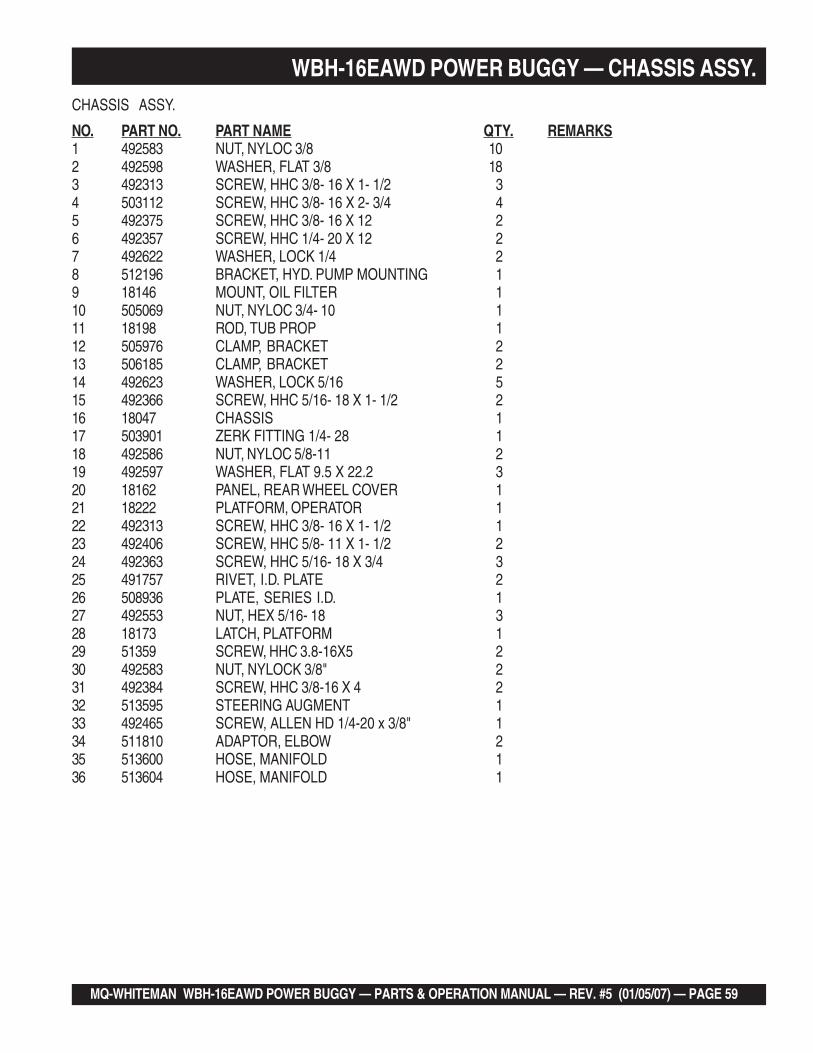
WBH-16EAWD POWER BUGGY — CHASSIS ASSY.CHASSIS ASSY.
NO. PART NO. PART NAME QTY. REMARKS1 492583 NUT, NYLOC 3/8 102 492598 WASHER, FLAT 3/8 183 492313 SCREW, HHC 3/8- 16 X 1- 1/2 34 503112 SCREW, HHC 3/8- 16 X 2- 3/4 45 492375 SCREW, HHC 3/8- 16 X 12 26 492357 SCREW, HHC 1/4- 20 X 12 27 492622 WASHER, LOCK 1/4 28 512196 BRACKET, HYD. PUMP MOUNTING 19 18146 MOUNT, OIL FILTER 110 505069 NUT, NYLOC 3/4- 10 111 18198 ROD, TUB PROP 112 505976 CLAMP, BRACKET 213 506185 CLAMP, BRACKET 214 492623 WASHER, LOCK 5/16 515 492366 SCREW, HHC 5/16- 18 X 1- 1/2 216 18047 CHASSIS 117 503901 ZERK FITTING 1/4- 28 118 492586 NUT, NYLOC 5/8-11 219 492597 WASHER, FLAT 9.5 X 22.2 320 18162 PANEL, REAR WHEEL COVER 121 18222 PLATFORM, OPERATOR 122 492313 SCREW, HHC 3/8- 16 X 1- 1/2 123 492406 SCREW, HHC 5/8- 11 X 1- 1/2 224 492363 SCREW, HHC 5/16- 18 X 3/4 325 491757 RIVET, I.D. PLATE 226 508936 PLATE, SERIES I.D. 127 492553 NUT, HEX 5/16- 18 328 18173 LATCH, PLATFORM 129 51359 SCREW, HHC 3.8-16X5 230 492583 NUT, NYLOCK 3/8" 231 492384 SCREW, HHC 3/8-16 X 4 232 513595 STEERING AUGMENT 133 492465 SCREW, ALLEN HD 1/4-20 x 3/8" 134 511810 ADAPTOR, ELBOW 235 513600 HOSE, MANIFOLD 136 513604 HOSE, MANIFOLD 1

PAGE 60 — MQ-WHITEMAN WBH-16EAWD POWER BUGGY — PARTS & OPERATION MANUAL — REV. 5 (01/05/07)
WBH-16EAWD POWER BUGGY — DUMP PEDAL AND HANDLE ASSY.DUMP PEDAL AND HANDLE ASSY.

MQ-WHITEMAN WBH-16EAWD POWER BUGGY — PARTS & OPERATION MANUAL — REV. #5 (01/05/07) — PAGE 61
DUMP PEDAL AND HANDLE ASSY.
NO. PART NO. PART NAME QTY. REMARKS1 492401 SCREW, HHC 1/2- 13 X 4 12 512184 NUT, NYLOC 3/16- 24 13 18121 KNOB, LEVER 14 18065 LEVER, DUMP VALVE 15 512185 SCREW, HHC 1/4- 20 X1- 3/4 26 492622 WASHER, LOCK 1/4 17 512183 SCREW, HHC 3/16- 24 X1- 1/4 18 18064 VALVE, DUMP ......................................1 ............ INCLUDES ITEMS W/*9* PIN, DUMP VALVE CROSS ..................1 ............ CANNOT BE PURCHASED SEPERATELY10 492596 WASHER, FLAT 1/4 111 492581 NUT, NYLOC 1/4- 20 112 492584 NUT, NYLOC 1/2- 13 213 492600 WASHER, FLAT 1/2 114 18152 PEDAL, DUMP VALVE 115 18123 CLEVIS , ASSY. DUMP VALVE 216 511761 NUT, HEX 3/8- 24 NF 217 18153 ROD, DUMP VALVE 118 492400 SCREW, HHC 1/2- 13 X 3- 1/2 119 18122 BELL CRANK, DUMP VALVE 1
WBH-16EAWD POWER BUGGY — DUMP PEDAL AND HANDLE ASSY.

PAGE 62 — MQ-WHITEMAN WBH-16EAWD POWER BUGGY — PARTS & OPERATION MANUAL — REV. 5 (01/05/07)
WBH-16EAWD POWER BUGGY — HYDRAULIC OIL TANK ASSY.
HYDRAULIC OIL TANK ASSY.

MQ-WHITEMAN WBH-16EAWD POWER BUGGY — PARTS & OPERATION MANUAL — REV. #5 (01/05/07) — PAGE 63
WBH-16EAWD POWER BUGGY — HYDRAULIC OIL TANK ASSY.
HYDRAULIC OIL TANK ASSY.
NO. PART NO. PART NAME QTY. REMARKS1 3336 SIGHT GAUGE, HYD. OIL TANK 12 16477 CAP, HYD. OIL TANK 13 18113 TANK HYD. OIL 14 492375 SCREW, HHC 3/8- 16 X1 35 491212 PLUG, HYD. OIL TANK 1/2’’ 16 492598 WASHER, FLAT 3/8 37 492583 NUT, NYLOC 3/8- 16 38 49123 PLUG, HYD. OIL TANK 3/4 19 492373 SCREW, HHC 3/8- 16 X 3/4 210 492624 WASHER, LOCK 3/8 211 18229 SCREEN, OIL RESERVOIR 2

PAGE 64 — MQ-WHITEMAN WBH-16EAWD POWER BUGGY — PARTS & OPERATION MANUAL — REV. 5 (01/05/07)
WBH-16EAWD POWER BUGGY — BATTERY (OPTIONAL ELECTRIC START)
HYDRAULIC OIL TANK ASSY.

MQ-WHITEMAN WBH-16EAWD POWER BUGGY — PARTS & OPERATION MANUAL — REV. #5 (01/05/07) — PAGE 65
WBH-16EAWD POWER BUGGY — BATTERY (OPTIONAL ELECTRIC START)
BATTERY (OPTIONAL ELECTRIC START)
NO. PART NO. PART NAME QTY. REMARKS2 505500 WINGNUT 24 512557 BATTERY CABLE, NEGATIVE 16 511250 BATTERY CABLE, POSITIVE 18 512555 BATTERY SUPPORT BRACKET 110 492596 WASHER, FLAT 1/4" 212 2101402 WASHER, LOCK 1/4" ............................. 2 ................REPLACES 49262214 492595 WASHER, FLAT 3/16" 416 508480 BATTERY SUPPORT PLATFORM 118 503118 BOLT 3/16" x 1" 220 503119 NUT 3/16" 222 512585 SUPPORT BRACKET BOLT 224 4671 BATTERY 1

PAGE 66 — MQ-WHITEMAN WBH-16EAWD POWER BUGGY — PARTS & OPERATION MANUAL — REV. 5 (01/05/07)
WBH-16EAWD POWER BUGGY — FUEL TANK ASSY.FUEL TANK ASSY.

MQ-WHITEMAN WBH-16EAWD POWER BUGGY — PARTS & OPERATION MANUAL — REV. #5 (01/05/07) — PAGE 67
WBH-16EAWD POWER BUGGY — FUEL TANK ASSY.FUEL TANK ASSY.
NO. PART NO. PART NAME QTY. REMARKS1 EM923343 WASHER, LOCK 5/16 42 EM492299 SCREW, HHC 5/16-18 X 1/2 43 EM923023 WASHER, FLAT 5/16 44 18280 COLLAR, STEERING SHAFT 15 18166 CAP, FUEL 16 18042 TUBE, FUEL TANK BREATHER 17 506208 CLAMP, FUEL HOSE 58 512269 HOSE, BREATHER 19 20795 SEAL, FUEL TANK GROMMET 210 19661 VALVE, FUEL SHUT-OFF 111 512192 HOSE, FUEL 112 EM20763 FILTER, FUEL 213 512191 HOSE, FUEL 114 511807 STRAP NYLON 5/8 115 18103 COVER, FUEL TANK 116 18098 TANK, FUEL 1

PAGE 68 — MQ-WHITEMAN WBH-16EAWD POWER BUGGY — PARTS & OPERATION MANUAL — REV. 5 (01/05/07)
Effective: February 22, 2006 TERMS AND CONDITIONS OF SALE — PARTS
PAYMENT TERMS
Terms of payment for parts are net 30 days.
FREIGHT POLICY
All parts orders will be shipped collect orprepaid with the charges added to the invoice.All shipments are F.O.B. point of origin.Multiquip’s responsibility ceases when a signedmanifest has been obtained from the carrier,and any claim for shortage or damage must besettled between the consignee and the carrier.
MINIMUM ORDER
The minimum charge for orders from Multiquipis $15.00 net. Customers will be asked forinstructions regarding handling of orders notmeeting this requirement.
RETURNED GOODS POLICY
Return shipments will be accepted and creditwill be allowed, subject to the following provi-sions:
1. A Returned Material Authorization mustbe approved by Multiquip prior to ship-ment.
2. To obtain a Return Material Authorization,a list must be provided to Multiquip PartsSales that defines item numbers, quanti-ties, and descriptions of the items to bereturned.
a. The parts numbers and descriptionsmust match the current parts pricelist.
b. The list must be typed or computergenerated.
c. The list must state the reason(s) forthe return.
d. The list must reference the salesorder(s) or invoice(s) under which theitems were originally purchased.
e. The list must include the name andphone number of the person request-ing the RMA.
3. A copy of the Return Material Authoriza-tion must accompany the return shipment.
4. Freight is at the sender’s expense. Allparts must be returned freight prepaid toMultiquip’s designated receiving point.
5. Parts must be in new and resalable con-dition, in the original Multiquip package (ifany), and with Multiquip part numbersclearly marked.
6. The following items are not returnable:
a. Obsolete parts. (If an item is in theprice book and shows as being re-placed by another item, it is obsolete.)
b. Any parts with a limited shelf life(such as gaskets, seals, “O” rings,and other rubber parts) that were pur-chased more than six months prior tothe return date.
c. Any line item with an extended dealernet price of less than $5.00.
d. Special order items.
e. Electrical components.
f. Paint, chemicals, and lubricants.
g. Decals and paper products.
h. Items purchased in kits.
7. The sender will be notified of any materialreceived that is not acceptable.
8. Such material will be held for five workingdays from notification, pending instruc-tions. If a reply is not received within fivedays, the material will be returned to thesender at his expense.
9. Credit on returned parts will be issued atdealer net price at time of the originalpurchase, less a 15% restocking charge.
10. In cases where an item is accepted, forwhich the original purchase documentcan not be determined, the price will bebased on the list price that was effectivetwelve months prior to the RMA date.
11. Credit issued will be applied to futurepurchases only.
PRICING AND REBATES
Prices are subject to change without priornotice. Price changes are effective on a spe-cific date and all orders received on or after thatdate will be billed at the revised price. Rebatesfor price declines and added charges for priceincreases will not be made for stock on handat the time of any price change.
Multiquip reserves the right to quote and selldirect to Government agencies, and to OriginalEquipment Manufacturer accounts who useour products as integral parts of their ownproducts.
SPECIAL EXPEDITING SERVICE
A $35.00 surcharge will be added to the invoicefor special handling including bus shipments,insured parcel post or in cases where Multiquipmust personally deliver the parts to the carrier.
LIMITATIONS OF SELLER’S LIABILITY
Multiquip shall not be liable hereunder fordamages in excess of the purchase price of theitem with respect to which damages areclaimed, and in no event shall Multiquip beliable for loss of profit or good will or for anyother special, consequential or incidental dam-ages.
LIMITATION OF WARRANTIES
No warranties, express or implied, are madein connection with the sale of parts or tradeaccessories nor as to any engine not manufac-tured by Multiquip. Such warranties made inconnection with the sale of new, complete unitsare made exclusively by a statement of war-ranty packaged with such units, and Multiquipneither assumes nor authorizes any person toassume for it any other obligation or liabilitywhatever in connection with the sale of itsproducts. Apart from such written statement ofwarranty, there are no warranties, express,implied or statutory, which extend beyond thedescription of the products on the face hereof.

MQ-WHITEMAN WBH-16EAWD POWER BUGGY — PARTS & OPERATION MANUAL — REV. #5 (01/05/07) — PAGE 69
NOTE PAGE
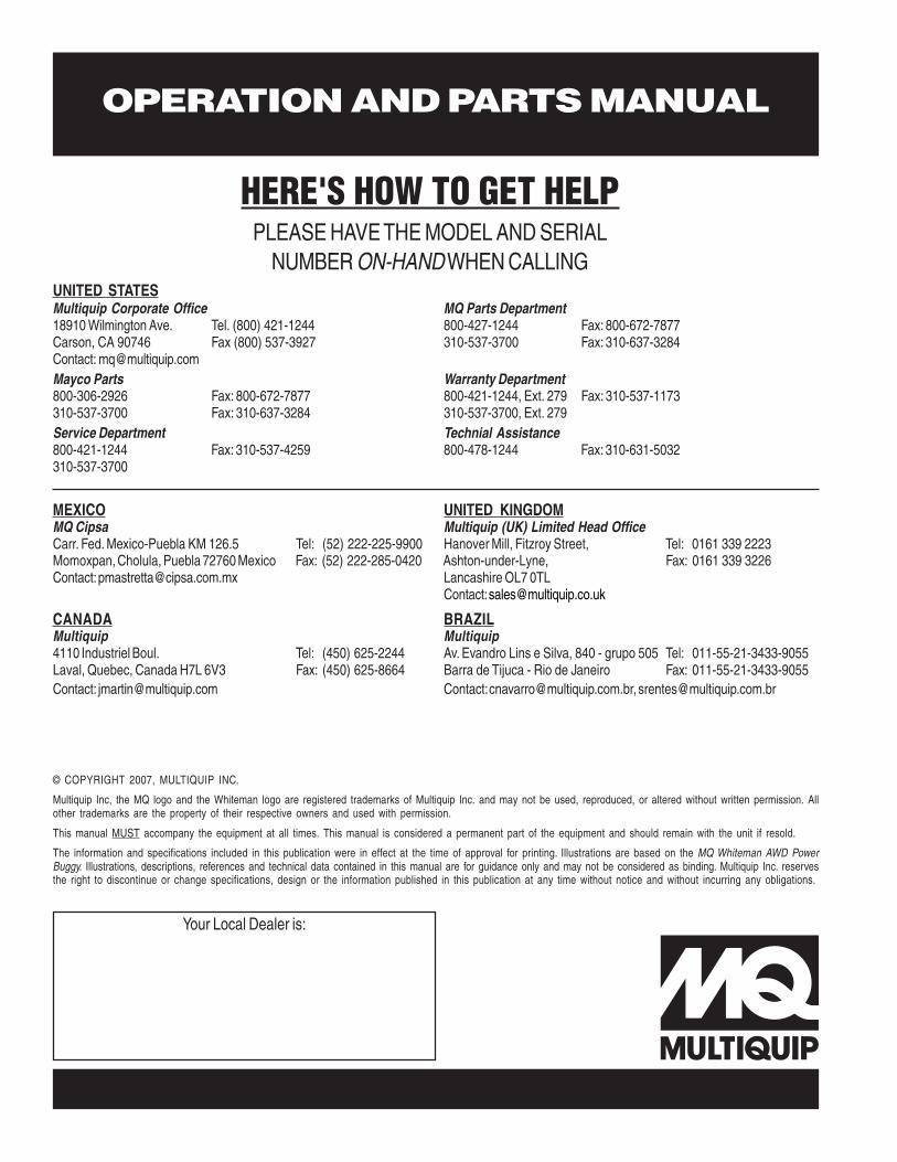
^^^^^*^^^^^^^^^^^^^^^^^^^^^^^^^*^6668
OPERATION AND PARTS MANUAL
Your Local Dealer is:
HERE'S HOW TO GET HELPPLEASE HAVE THE MODEL AND SERIAL
NUMBER ON-HAND WHEN CALLING
© COPYRIGHT 2007, MULTIQUIP INC.
Multiquip Inc, the MQ logo and the Whiteman logo are registered trademarks of Multiquip Inc. and may not be used, reproduced, or altered without written permission. Allother trademarks are the property of their respective owners and used with permission.
This manual MUST accompany the equipment at all times. This manual is considered a permanent part of the equipment and should remain with the unit if resold.
The information and specifications included in this publication were in effect at the time of approval for printing. Illustrations are based on the MQ Whiteman AWD PowerBuggy. Illustrations, descriptions, references and technical data contained in this manual are for guidance only and may not be considered as binding. Multiquip Inc. reservesthe right to discontinue or change specifications, design or the information published in this publication at any time without notice and without incurring any obligations.
UNITED STATESMultiquip Corporate Office MQ Parts Department18910 Wilmington Ave. Tel. (800) 421-1244 800-427-1244 Fax: 800-672-7877Carson, CA 90746 Fax (800) 537-3927 310-537-3700 Fax: 310-637-3284Contact: [email protected] Parts Warranty Department800-306-2926 Fax: 800-672-7877 800-421-1244, Ext. 279 Fax: 310-537-1173310-537-3700 Fax: 310-637-3284 310-537-3700, Ext. 279Service Department Technial Assistance800-421-1244 Fax: 310-537-4259 800-478-1244 Fax: 310-631-5032310-537-3700
MEXICO UNITED KINGDOMMQ Cipsa Multiquip (UK) Limited Head OfficeCarr. Fed. Mexico-Puebla KM 126.5 Tel: (52) 222-225-9900 Hanover Mill, Fitzroy Street, Tel: 0161 339 2223Momoxpan, Cholula, Puebla 72760 Mexico Fax: (52) 222-285-0420 Ashton-under-Lyne, Fax: 0161 339 3226Contact: [email protected] Lancashire OL7 0TL
Contact: [email protected]
CANADA BRAZILMultiquip Multiquip4110 Industriel Boul. Tel: (450) 625-2244 Av. Evandro Lins e Silva, 840 - grupo 505 Tel: 011-55-21-3433-9055Laval, Quebec, Canada H7L 6V3 Fax: (450) 625-8664 Barra de Tijuca - Rio de Janeiro Fax: 011-55-21-3433-9055Contact: [email protected] Contact: [email protected], [email protected]