awe b8 s4 s5 ventboostgauge 1 - awe tuning: … · boost gauge kit for the 2010+ audi s4 and s5...
TRANSCRIPT

2010+ Audi S4, S5, S5 Cabrio2010+ Audi S4, S5, S5 Cabrio2010+ Audi S4, S5, S5 Cabrio2010+ Audi S4, S5, S5 Cabrio Vent Boost Gauge Kit Vent Boost Gauge Kit Vent Boost Gauge Kit Vent Boost Gauge Kit
and Boost Tapand Boost Tapand Boost Tapand Boost Tap Contact us with any installation questions. Contact us with any installation questions. Contact us with any installation questions. Contact us with any installation questions. 215-658-1670 AWE-Tuning.com [email protected]
Congratulations on your purchase of the AWE Tuning Vent
Boost Gauge Kit for the 2010+ Audi S4 and S5 3.0T and S5 Cab-
rio.
Exquisite build quality with industry leading performance
distinguishes this gauge kit from all others.
Copyright 2012, AWE Tuning. No part of this document may be reused or duplicated without the express permission of AWE Tuning/Secor Ltd. All rights reserved. Rev1.3
INSTALLATION GUIDE
2
1 preassembled AWE Tuning vent and gauge pod
1 boost hose
1 sender unit with wiring harness
1 gauge wiring harness
1 fume 8lter
1 6mm T-8tting
1 machined boost tap plate
1 3/16” vacuum cap
1 22” length of additional boost hose
2 red wiring loop terminal
2 red posi-tap connector
4 red butt connectors
1 8” long black wire
1 8” long white wire
2 8” long red wire
6 medium zip tie
9 small zip tie
Required tools and materials:Required tools and materials:Required tools and materials:Required tools and materials:
Flathead screwdriver
T-30 torx bit
Ratchet
Extension
13mm socket
10mm socket
8mm socket
Razor blade
Wire strippers/cutters
Electrical tape
Drill
7/16” drill bit
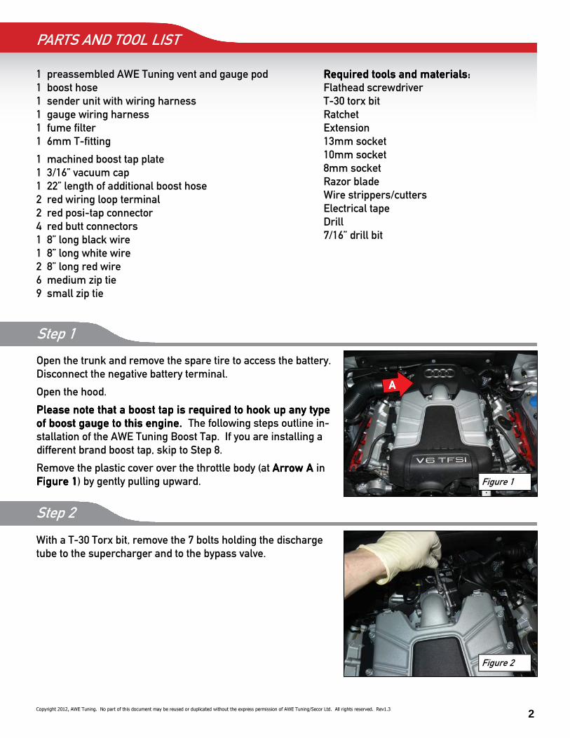
Step 1
Open the trunk and remove the spare tire to access the battery.
Disconnect the negative battery terminal.
Open the hood.
Please note that a boost tap is required to hook up any type Please note that a boost tap is required to hook up any type Please note that a boost tap is required to hook up any type Please note that a boost tap is required to hook up any type
of boost gauge to this engine. of boost gauge to this engine. of boost gauge to this engine. of boost gauge to this engine. The following steps outline in-
stallation of the AWE Tuning Boost Tap. If you are installing a
different brand boost tap, skip to Step 8.
Remove the plastic cover over the throttle body (at Arrow A Arrow A Arrow A Arrow A in
Figure 1Figure 1Figure 1Figure 1) by gently pulling upward.
PARTS AND TOOL LIST
Copyright 2012, AWE Tuning. No part of this document may be reused or duplicated without the express permission of AWE Tuning/Secor Ltd. All rights reserved. Rev1.3
AAAA
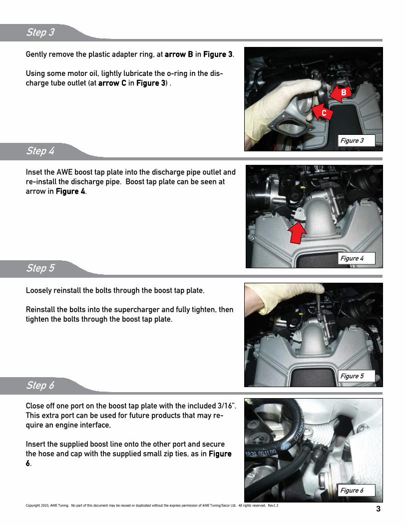
Step 2
With a T-30 Torx bit, remove the 7 bolts holding the discharge
tube to the supercharger and to the bypass valve.
Figure 1
Figure 2
3
Figure 3
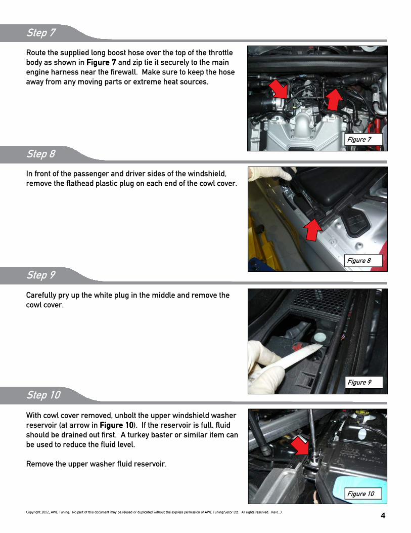
Gently remove the plastic adapter ring, at arrow B arrow B arrow B arrow B in Figure 3Figure 3Figure 3Figure 3.
Using some motor oil, lightly lubricate the o-ring in the dis-
charge tube outlet (at arrow C arrow C arrow C arrow C in Figure 3Figure 3Figure 3Figure 3) .
Inset the AWE boost tap plate into the discharge pipe outlet and
re-install the discharge pipe. Boost tap plate can be seen at
arrow in Figure 4Figure 4Figure 4Figure 4.
Loosely reinstall the bolts through the boost tap plate.
Reinstall the bolts into the supercharger and fully tighten, then
tighten the bolts through the boost tap plate.
Close off one port on the boost tap plate with the included 3/16”.
This extra port can be used for future products that may re-
quire an engine interface,
Insert the supplied boost line onto the other port and secure
the hose and cap with the supplied small zip ties, as in Figure Figure Figure Figure
6666.
Step 3
Step 4
Step 5
Step 6
Figure 4
Figure 5
Figure 6
BBBB
CCCC
Copyright 2010, AWE Tuning. No part of this document may be reused or duplicated without the express permission of AWE Tuning/Secor Ltd. All rights reserved. Rev1.3
4
Route the supplied long boost hose over the top of the throttle
body as shown in Figure 7 Figure 7 Figure 7 Figure 7 and zip tie it securely to the main
engine harness near the 8rewall. Make sure to keep the hose
away from any moving parts or extreme heat sources.
Step 7
In front of the passenger and driver sides of the windshield,
remove the Dathead plastic plug on each end of the cowl cover.
Step 8
Carefully pry up the white plug in the middle and remove the
cowl cover.
Step 9
Figure 7
Figure 8
Figure 9
With cowl cover removed, unbolt the upper windshield washer
reservoir (at arrow in Figure 10Figure 10Figure 10Figure 10). If the reservoir is full, Duid
should be drained out 8rst. A turkey baster or similar item can
be used to reduce the Duid level.
Remove the upper washer Duid reservoir.
Figure 10
Step 10
Copyright 2012, AWE Tuning. No part of this document may be reused or duplicated without the express permission of AWE Tuning/Secor Ltd. All rights reserved. Rev1.3
5 Copyright 2012, AWE Tuning. No part of this document may be reused or duplicated without the express permission of AWE Tuning/Secor Ltd. All rights reserved. Rev1.3
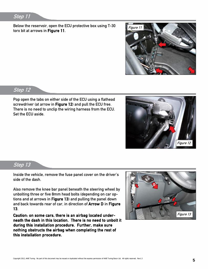
Below the reservoir, open the ECU protective box using T-30
torx bit at arrows in Figure 11Figure 11Figure 11Figure 11.
Figure 11
Step 11
Step 12
Figure 12
Pop open the tabs on either side of the ECU using a Dathead
screwdriver (at arrow in Figure 12Figure 12Figure 12Figure 12) and pull the ECU free.
There is no need to unclip the wiring harness from the ECU.
Set the ECU aside.
Step 13
Inside the vehicle, remove the fuse panel cover on the driver’s
side of the dash.
Also remove the knee bar panel beneath the steering wheel by
unbolting three or 8ve 8mm head bolts (depending on car op-
tions and at arrows in Figure 13Figure 13Figure 13Figure 13) and pulling the panel down
and back towards rear of car, in direction of Arrow D Arrow D Arrow D Arrow D in Figure Figure Figure Figure
13131313.
Caution: on some cars, there is an airbag located under-Caution: on some cars, there is an airbag located under-Caution: on some cars, there is an airbag located under-Caution: on some cars, there is an airbag located under-
neath the dash in this location. There is no need to unbolt it neath the dash in this location. There is no need to unbolt it neath the dash in this location. There is no need to unbolt it neath the dash in this location. There is no need to unbolt it
during this installation procedure. Further, make sure during this installation procedure. Further, make sure during this installation procedure. Further, make sure during this installation procedure. Further, make sure
nothing obstructs the airbag when completing the rest of nothing obstructs the airbag when completing the rest of nothing obstructs the airbag when completing the rest of nothing obstructs the airbag when completing the rest of
this installation procedure.this installation procedure.this installation procedure.this installation procedure.
Figure 13
DDDD

6 Copyright 2012, AWE Tuning. No part of this document may be reused or duplicated without the express permission of AWE Tuning/Secor Ltd. All rights reserved. Rev1.3
Figure 15
Step 14
Back under the hood, carefullycarefullycarefullycarefully make a 1/4” slice in the rubber
wiring harness boot on the front of the driver side 8rewall, as
in Figure 14.Figure 14.Figure 14.Figure 14.
Then carefullycarefullycarefullycarefully make a 1/4” slice in the rubber wiring harness
boot at the inlet to the ECU box, as in Figure 15Figure 15Figure 15Figure 15.
Figure 14
Feed the enclosed boost hose through the slice in the 8rewall
rubber boot, at arrow in Figure 16.Figure 16.Figure 16.Figure 16.
And then feed it through the slice in the ECU box rubber boot, at
arrow in Figure 17Figure 17Figure 17Figure 17, into the ECU box.
Figure 16
Figure 17
Step 15
7
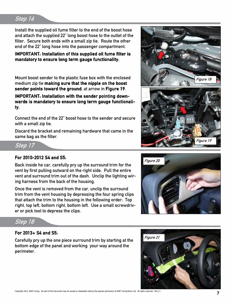
Step 16
Install the supplied oil fume 8lter to the end of the boost hose
and attach the supplied 22” long boost hose to the outlet of the
8lter. Secure both ends with a small zip tie. Route the other
end of the 22” long hose into the passenger compartment.
IMPORTANT: Installation of this supplied oil fume 8lter is IMPORTANT: Installation of this supplied oil fume 8lter is IMPORTANT: Installation of this supplied oil fume 8lter is IMPORTANT: Installation of this supplied oil fume 8lter is
mandatory to ensure long term gauge functionality. mandatory to ensure long term gauge functionality. mandatory to ensure long term gauge functionality. mandatory to ensure long term gauge functionality.
Mount boost sender to the plastic fuse box with the enclosed
medium zip tie making sure that the nipple on the boost making sure that the nipple on the boost making sure that the nipple on the boost making sure that the nipple on the boost
sender points toward the groundsender points toward the groundsender points toward the groundsender points toward the ground, at arrow in Figure 19Figure 19Figure 19Figure 19.
IMPORTANT: Installation with the sender pointing down-IMPORTANT: Installation with the sender pointing down-IMPORTANT: Installation with the sender pointing down-IMPORTANT: Installation with the sender pointing down-
wards is mandatory to ensure long term gauge functionali-wards is mandatory to ensure long term gauge functionali-wards is mandatory to ensure long term gauge functionali-wards is mandatory to ensure long term gauge functionali-
ty.ty.ty.ty.
Connect the end of the 22” boost hose to the sender and secure
with a small zip tie.
Discard the bracket and remaining hardware that came in the
same bag as the 8lter.
For 2010For 2010For 2010For 2010----2012 S4 and S5:2012 S4 and S5:2012 S4 and S5:2012 S4 and S5:
Back inside he car, carefully pry up the surround trim for the
vent by 8rst pulling outward on the right side. Pull the entire
vent and surround trim out of the dash. Unclip the lighting wir-
ing harness from the back of the housing.
Once the vent is removed from the car, unclip the surround
trim from the vent housing by depressing the four spring clips
that attach the trim to the housing in the following order: Top
right, top left, bottom right, bottom left. Use a small screwdriv-
er or pick tool to depress the clips.
Step 17
Figure 20
Copyright 2012, AWE Tuning. No part of this document may be reused or duplicated without the express permission of AWE Tuning/Secor Ltd. All rights reserved. Rev1.3
Figure 18
Figure 19
Step 18
For 2013+ S4 and S5:For 2013+ S4 and S5:For 2013+ S4 and S5:For 2013+ S4 and S5:
Carefully pry up the one piece surround trim by starting at the
bottom edge of the panel and working your way around the
perimeter.
Figure 21
8 Copyright 2012, AWE Tuning. No part of this document may be reused or duplicated without the express permission of AWE Tuning/Secor Ltd. All rights reserved. Rev1.3
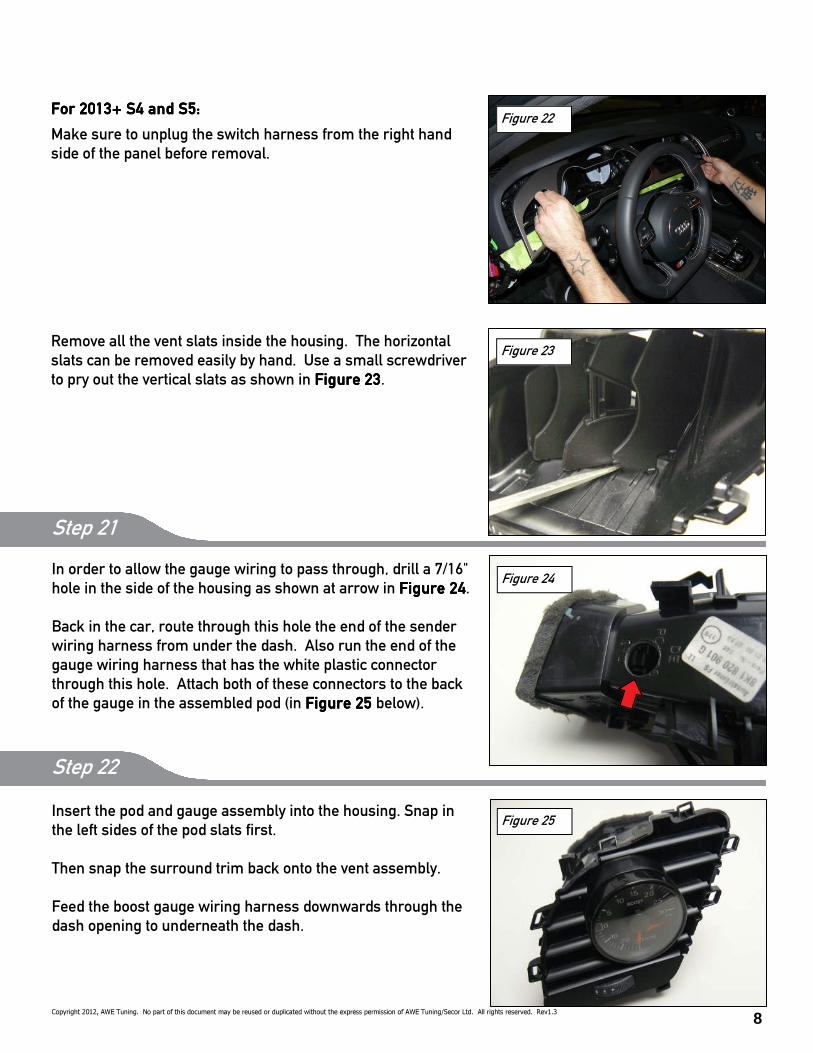
For 2013+ S4 and S5:For 2013+ S4 and S5:For 2013+ S4 and S5:For 2013+ S4 and S5:
Make sure to unplug the switch harness from the right hand
side of the panel before removal.
Step 19
Figure 22
Remove all the vent slats inside the housing. The horizontal
slats can be removed easily by hand. Use a small screwdriver
to pry out the vertical slats as shown in Figure 23Figure 23Figure 23Figure 23.
Step 20
Figure 23
Insert the pod and gauge assembly into the housing. Snap in
the left sides of the pod slats 8rst.
Then snap the surround trim back onto the vent assembly.
Feed the boost gauge wiring harness downwards through the
dash opening to underneath the dash.
Step 22
Figure 25
Step 21
In order to allow the gauge wiring to pass through, drill a 7/16"
hole in the side of the housing as shown at arrow in Figure 24Figure 24Figure 24Figure 24.
Back in the car, route through this hole the end of the sender
wiring harness from under the dash. Also run the end of the
gauge wiring harness that has the white plastic connector
through this hole. Attach both of these connectors to the back
of the gauge in the assembled pod (in Figure 25 Figure 25 Figure 25 Figure 25 below).
Figure 24
9 Copyright 2012, AWE Tuning. No part of this document may be reused or duplicated without the express permission of AWE Tuning/Secor Ltd. All rights reserved. Rev1.3
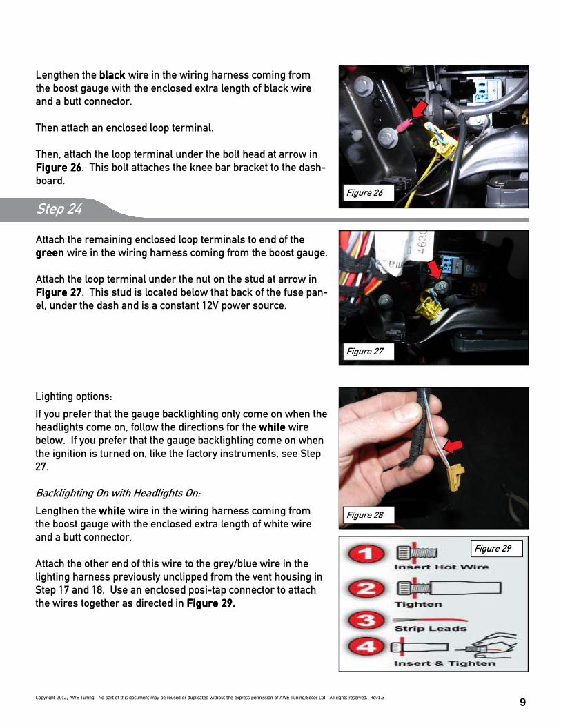
Attach the remaining enclosed loop terminals to end of the
greengreengreengreen wire in the wiring harness coming from the boost gauge.
Attach the loop terminal under the nut on the stud at arrow in
Figure 27Figure 27Figure 27Figure 27. This stud is located below that back of the fuse pan-
el, under the dash and is a constant 12V power source.
Lengthen the black black black black wire in the wiring harness coming from
the boost gauge with the enclosed extra length of black wire
and a butt connector.
Then attach an enclosed loop terminal.
Then, attach the loop terminal under the bolt head at arrow in
Figure 26Figure 26Figure 26Figure 26. This bolt attaches the knee bar bracket to the dash-
board. Figure 26
Step 24
Step 23
Figure 27
Lighting options:
If you prefer that the gauge backlighting only come on when the
headlights come on, follow the directions for the whitewhitewhitewhite wire
below. If you prefer that the gauge backlighting come on when
the ignition is turned on, like the factory instruments, see Step
27.
Backlighting On with Headlights On:
Lengthen the white white white white wire in the wiring harness coming from
the boost gauge with the enclosed extra length of white wire
and a butt connector.
Attach the other end of this wire to the grey/blue wire in the
lighting harness previously unclipped from the vent housing in
Step 17 and 18. Use an enclosed posi-tap connector to attach
the wires together as directed in Figure 29.Figure 29.Figure 29.Figure 29.
Figure 28
Step 25
Figure 29
10
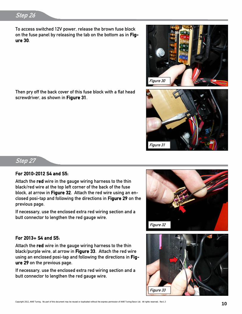
Figure 30
To access switched 12V power, release the brown fuse block
on the fuse panel by releasing the tab on the bottom as in Fig-Fig-Fig-Fig-
ure 30ure 30ure 30ure 30.
Then pry off the back cover of this fuse block with a Dat head
screwdriver, as shown in Figure 31Figure 31Figure 31Figure 31.
Copyright 2012, AWE Tuning. No part of this document may be reused or duplicated without the express permission of AWE Tuning/Secor Ltd. All rights reserved. Rev1.3
Step 26
Figure 31
For 2010For 2010For 2010For 2010----2012 S4 and S5:2012 S4 and S5:2012 S4 and S5:2012 S4 and S5:
Attach the redredredred wire in the gauge wiring harness to the thin
black/red wire at the top left corner of the back of the fuse
block, at arrow in Figure 32Figure 32Figure 32Figure 32. Attach the red wire using an en-
closed posi-tap and following the directions in Figure 29 Figure 29 Figure 29 Figure 29 on the
previous page.
If necessary, use the enclosed extra red wiring section and a
butt connector to lengthen the red gauge wire.
For 2013+ S4 and S5:For 2013+ S4 and S5:For 2013+ S4 and S5:For 2013+ S4 and S5:
Attach the red red red red wire in the gauge wiring harness to the thin
black/purple wire, at arrow in Figure 33Figure 33Figure 33Figure 33. Attach the red wire
using an enclosed posi-tap and following the directions in Fig-Fig-Fig-Fig-
ure 29ure 29ure 29ure 29 on the previous page.
If necessary, use the enclosed extra red wiring section and a
butt connector to lengthen the red gauge wire.
Figure 32
Figure 33
Step 27
11
ENJOY
Check for operation of the gauge at this time by starting the engine. You should see ~17-22 in/hg of vacu-
um at idle, and the gauge lighting should turn on and off with the headlight switch.
The balance of re-assembly is reverse of removal. Do not forget to top off your windshield washer Duid!
A boost gauge is a valuable tool in determining your car’s state of performance.
Any questions or comments,
please do not hesitate to contact us:
1-888-565-2257
AWE-Tuning.com
Copyright 2012, AWE Tuning. No part of this document may be reused or duplicated without the express permission of AWE Tuning/Secor Ltd. All rights reserved. Rev1.3
Step 29
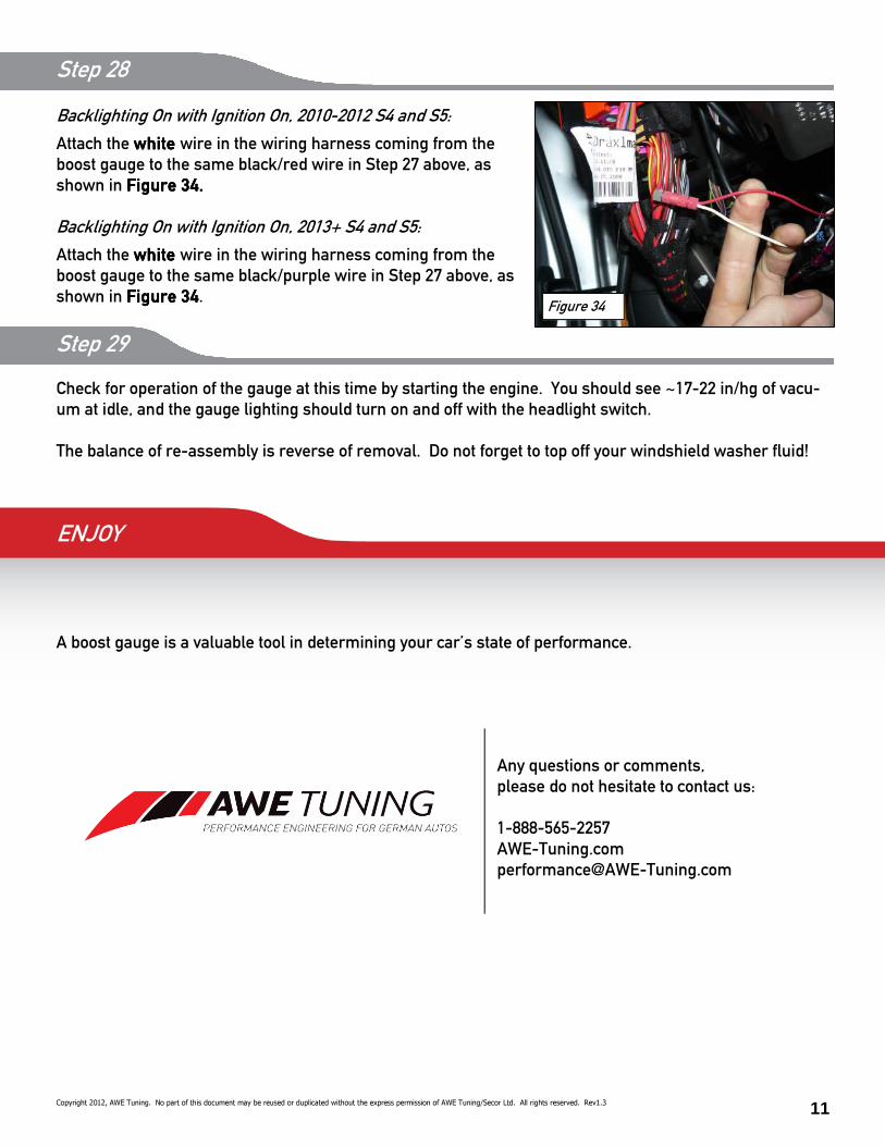
Backlighting On with Ignition On, 2010-2012 S4 and S5:
Attach the white white white white wire in the wiring harness coming from the
boost gauge to the same black/red wire in Step 27 above, as
shown in Figure 34.Figure 34.Figure 34.Figure 34.
Backlighting On with Ignition On, 2013+ S4 and S5:
Attach the white white white white wire in the wiring harness coming from the
boost gauge to the same black/purple wire in Step 27 above, as
shown in Figure 34Figure 34Figure 34Figure 34.
Step 28
Figure 34

12
Thank you for choosing AWE Tuning as your performance automotive parts supplier. Please remember
that a performance car is only as strong as its weakest link. Therefore, it is vital that you maintain your
vehicle to factory speci8cations.
By installing or using the purchased product, the Consumer accepts this warranty and any speci8c By installing or using the purchased product, the Consumer accepts this warranty and any speci8c By installing or using the purchased product, the Consumer accepts this warranty and any speci8c By installing or using the purchased product, the Consumer accepts this warranty and any speci8c
Manufacturer warranties enclosed.Manufacturer warranties enclosed.Manufacturer warranties enclosed.Manufacturer warranties enclosed.
Limited Warranty
The following warranty is valid only in the United States.
The Manufacturer’s full warranty applies to all products sold.
Secor Ltd. (AWE Tuning) warrants to the original retail purchaser (Consumer) this product (B8/B8.5 S4/S5
Cabrio Vent Boost Gauge Kit and Boost Tap) against manufacturing defects for ONE YEAR from date of
original purchase.
Upon veri8cation of warranty coverage, AWE Tuning will repair or replace the defective product at their
discretion, without charge. This is the only remedy the Consumer has for any loss or damage, however
arising, due to nonconformity in or defect of the product. This warranty does not cover consequential dam-
age, loss of time or revenues, installation labor costs, inconvenience, loss of use of vehicle, shipping costs,
damage to the vehicle or components, or other incidental or indirect damage.
All warranties are void if the product was not installed by a certi8ed auto mechanic, improperly serviced,
modi8ed, or used in a way not intended by the Manufacturer. Use of product in Motorsports or Racing
conditions is grounds for warranty denial. Motorsports and Racing is an inherently abusive operational
condition, and it is impossible to warranty for this type of usage.
The Consumer is responsible for ensuring that the product is installed in a safe and proper manner, and
should cease usage of the product immediately if an unsafe or improper condition is noted. If an unsafe or
improper condition is noted, the Consumer should then immediately contact the facility where the product
was installed or AWE Tuning directly.
Please contact the original place of purchase for any warranty claims or explanations of this document.
AWE Tuning
2385C Maryland Road
Willow Grove, PA 19090
215-658-1670
Copyright 2012, AWE Tuning. No part of this document may be reused or duplicated without the express permission of AWE Tuning/Secor Ltd. All rights reserved. Rev1.3