ax9150 umi installation / configuration manual - · pdf fileax9150 umi installation and...
TRANSCRIPT
Ax9150 UMI Installation / Configuration Manual

Ax9150 UMI Installation and Configuration Instructions - © 2010 Memex Automation Inc., All Rights Reserved
™ ®
P a g e | 1
Notice of Copyright Published by Memex Automation Inc.
Copyright © 2009-2012 All rights reserved.
Registered Trademarks and Proprietary Names Product names mentioned in this document may be trademarks or registered trademarks of Memex Automation Inc. or its affiliates, or other hardware, software, or service providers and are used herein for identification purposes only.
Printing Information First printing: October 2009
Applicability This document applies to the Memex Automation Inc. Ax9150 Universal Machine Interface hardware and related software. Memex Automation Inc. and its affiliates, employees, dealers or agents are not responsible for any damages, however caused, as a result of the use of this product and /or this installation manual. Caution should be exercised at all times especially when dealing with machine tools and their associated control units. Ownership Memex Automation Inc. retains the ownership of the associated software package. It is licensed to you for use with the Memex Automation Inc. Ax9150 Universal Machine Interface hardware. Rights Memex Automation Inc. retains all rights not expressly granted. Nothing in this license agreement constitutes a waiver of Memex Automation Inc.’s rights under copyright laws or any other Federal or State law. Limited Warranty If you discover physical defects in the hardware or media, Memex Automation Inc. will replace the hardware or media at no charge to you, provided you return the item to be replaced according to Memex’s Warranty & Returns Policy during the one year period after having taken delivery of the product. Memex Automation Inc. excludes any and all implied warranties, including warranties of merchantability and fitness for a particular purpose and limits your remedy to return the hardware, software and documentation to Memex Automation Inc. for replacement. Although Memex Automation Inc. has tested the hardware, software and reviewed the documentation, MEMEX AUTOMATION INC. MAKES NO WARRANTY OF REPRESENTATION, EITHER EXPRESSED OR IMPLIED, WITH RESPECT TO THIS HARDWARE, SOFTWARE OR DOCUMENTATION, ITS QUALITY, PERFORMANCE, MERCHANTABILITY, OR FITNESS FOR A PARTICULAR PURPOSE. AS A RESULT, THIS HARDWARE, SOFTWARE AND DOCUMENTATION ARE LICENSED “AS IS” AND YOU, THE LICENSEE, ARE ASSUMING THE ENTIRE RISK AS TO ITS QUALITY AND PERFORMANCE. IN NO EVENT WILL MEMEX AUTOMATION INC. BE LIABLE FOR DIRECT, INDIRECT, SPECIAL, INCIDENTAL OR CONSEQUENTIAL DAMAGES ARISING OUT OF THE USE OR INABILITY TO USE THE HARDWARE, SOFTWARE OR DOCUMENTATION, EVEN IF ADVISED OF THE POSSIBILITY OF SUCH DAMAGES. In particular, Memex Automation Inc. shall have no liability for any data stored or processed with this software, including the costs of recovering such data.
THE WARRANTY AND REMEDIES SET FORTH ABOVE ARE EXCLUSIVE AND IN LIEU OF ALL OTHERS, ORAL OR WRITTEN, EXPRESSED OR IMPLIED. No Memex Automation Inc. affiliate, dealer, agent, or employee is authorized to make any modifications or additions to this warranty.
Information in this document is subject to change without notice and does not represent a commitment on the part of Memex Automation Inc.. The software described in this document is furnished under this license agreement. The software may be used or copied only in accordance with the terms of the agreement.

Ax9150 UMI Installation and Configuration Instructions - © 2010 Memex Automation Inc., All Rights Reserved
™ ®
P a g e | 2
Memex Automation Inc. 3425 Harvester Rd., Suite 200, Burlington, Ontario L7N 3N1 Canada www.memex.ca
Table of Contents
Section A - General Considerations .....................................................................................................5
Section B - Placement Considerations / Installation Locations for the Ax9150 UMI and the Mx2000 HOI
Terminal ............................................................................................................................................5
Section C - Selecting the Best Method to Power the Ax9150 UMI........................................................7
C.1 – Diagram of Power and Digital Input wiring Rev01 Board - Overview .............................................. 8
C.2 – Diagram of Power and Digital Input wiring Rev02 Board - Overview .............................................. 9
Section D - Determining the Machine Signals that are to be Tracked by the Ax9150 .......................... 10
D.1 – Hard-wired Inputs .......................................................................................................................... 10
D.2 – User-Defined Inputs (Input 8 to Input 27) ..................................................................................... 11
D.3 - Default Pre-Defined Modes ............................................................................................................ 11
Section E - Wiring the Hard-wired Machine Signals on the Input Pins ................................................. 11
E.1 – Diagram of DC Input Types............................................................................................................. 12
E.2 – Diagram of Sourcing Type Inputs Rev02 ........................................................................................ 12
E.3 – Diagram of Sinking Type Inputs – Rev01 ........................................................................................ 13
E.4 – Diagram of Sinking Type Inputs Rev02 ........................................................................................... 13
Section F - Connecting the DNC Serial Cable and the Mx2000 HOI Terminal ....................................... 14
F.1 – Mx2000 Diagram ............................................................................................................................ 14
F.2 – Diagram of Mx2000 and Cord ........................................................................................................ 14
F.3 – Scepter Strain Relief for Mx2000 Installation Diagram .................................................................. 15
F.4 – RJ12 to DB9 Adapter Diagram ........................................................................................................ 16
F.5 – DB9 Pin-outs Diagram .................................................................................................................... 16
F.6 – Diagram of the RJ12 to DB9 Pin-outs ............................................................................................. 16
Section G - Connecting the Ethernet Cable ........................................................................................ 17
Section H - Connecting to the Network via AxConfig ......................................................................... 18
H.2 – Diagram of the AxConfig Launch Icon ........................................................................................... 19
H.1 – Diagram of the MAC Address Location .......................................................................................... 19
H.3 – Diagram - Launching AxConfig ....................................................................................................... 19
Ax9150 UMI Installation and Configuration Instructions - © 2010 Memex Automation Inc., All Rights Reserved
™ ®
P a g e | 3
H.4 – Diagram - Search for the Ax9150 ................................................................................................... 20
H.5 – Diagram - Assigning the Terminal ID in AxConfig .......................................................................... 21
H.6 – Diagram - Connection Established to the Network ....................................................................... 22
H.7 – Diagram - Communication Setup – Part 1 ..................................................................................... 23
H.8 – Diagram - Accessing the Terminal Window in AxConfig ................................................................ 24
H.9 – Diagram – The Command Terminal Window ................................................................................ 25
H.10 – Diagram - Assigning the Terminal ID via the Terminal Window .................................................. 26
H.11 – Diagram - Ax9150 Communication Setup - Part 2 ....................................................................... 27
H.12 – Diagram - Communication Setup Completed .............................................................................. 28
Section I - Configuring All Input Names (Hard-wired, User-defined, and Soft I/O) ............................... 29
I.1 – Diagram - Launch I/O Setup Screen ................................................................................................ 30
I.2 - Diagram – Main Ladder Configuration Screen ................................................................................. 31
I.4 - Diagram – Ladder I/O Settings: I/O Translation Tab ........................................................................ 32
I.5 – Diagram – Ladder I/O Settings: PACE Translation Tab .................................................................... 33
I.6 – Diagram – Input Settings Tab .......................................................................................................... 34
I.7 – Diagram - De-Bounce Truth Table for Selecting Correct Usage ...................................................... 35
Section J - Truth Table Development Utilizing the Mx2000 HOI Terminal ........................................... 36
J.1 – Diagram – PACE Translation Tab - Example .................................................................................... 37
J.2 – Diagram – I/O Translation Tab – Example ...................................................................................... 37
J.3 – Diagram – Truth Table Mapping From AxConfig – Example ........................................................... 38
J.3a – Diagram –Mx2000 with no Shift key pressed ............................................................................... 39
J.3b – Diagram –Mx2000 with Shift key pressed .................................................................................... 39
J.4 - Navigating to the DI Status Window with the Mx2000 ................................................................... 40
J.4a - Diagram– Mx2000 Main Menu .................................................................................................. 40
J.4b – Diagram – Mx2000 Configuration Menu .................................................................................. 40
J.4c – Diagram – Mx2000 Password Entry .......................................................................................... 41
J.4d – Diagram – Mx2000 Options Menu ............................................................................................ 41
J.4e – Diagram – Mx2000 Selection of Digital Input (DI) Status Mode ............................................... 42
J.4f – Diagram – Mx2000 DI Status Screen ......................................................................................... 42
J.5 - Example of a Completed Truth Table Form ..................................................................................... 43
J.5 – Diagram – Completed Truth Table Form - Example ....................................................................... 43

Ax9150 UMI Installation and Configuration Instructions - © 2010 Memex Automation Inc., All Rights Reserved
™ ®
P a g e | 4
J.6 - Checking Binary Values for Uniqueness/Redundancy ..................................................................... 44
J.7 - Flashing Signals ................................................................................................................................ 44
Section K - Ladder Development and Downloading to the Ax9150 via AxConfig ................................. 45
K.1 – Diagram – Main Ladder Configuration Screen ............................................................................... 45
K.2 - Review of Differences between Contact Types .............................................................................. 46
K.2a – Diagram – Normally Open Contact .......................................................................................... 46
K.2b – Diagram – Normally Closed Contact ........................................................................................ 46
K.3 - How to Write a Ladder Rung .......................................................................................................... 47
K.4 - Example Recap ................................................................................................................................ 47
K.5 - Key Points to Remember when Writing the Ladder Configuration File ......................................... 47
K.6 – Diagram – First Rung of Ladder Logic Complete - Example ........................................................... 48
K.7 – Diagram – All Hard-wired Ladder Rungs Complete - Example ....................................................... 49
K.8 – Diagram – All Ladder Rungs Complete - Example .......................................................................... 50
K.9 - Special Note on Ladder Programming ............................................................................................ 52
K.10 – Diagram – Ladder File Validation prior to Download................................................................... 53
K.11a – Diagram – Failed Validation – Timer defined but not used in ladder file .............................. 54
K.11b – Diagram - Failed Validation – Input conflict exists (use of duplicate input) .......................... 54
K.11c – Diagram – Failed Validation – Invalid input detected ............................................................ 55
K.11d – Diagram – Failed Validation – Duplicate timer used .............................................................. 55
K.11e – Diagram – Failed Validation – Invalid timer specified ............................................................ 56
K.12a – Diagram – Ladder Validated - Ready to be Sent to the Ax9150 UMI ..................................... 56
K.12b – Diagram – Ladder Configuration File being sent to the Ax9150 UMI .................................... 57
K.12c – Diagram – Ladder Configuration File - Sending completed.................................................... 57
Section L - Monitoring the Status of the Configuration Resident in the Ax9150 UMI ........................... 58
L.1 – Diagram – Ladder Monitoring in Run Mode ................................................................................... 59
Section M - Mx2000 HOI Terminal – Emulation ................................................................................. 60
M.1 – Diagram – Mx2000 Terminal Emulation via AxConfig .................................................................. 60
Section N - Ax9150 UMI Firmware Upgrade via AxConfig ................................................................... 61
N.1 - Diagram – Firmware Upgrade via AxConfig ................................................................................... 61
Appendix A – Blank Truth Table Form ............................................................................................... 62
Appendix B – Sample CNC Program to Prove Truth Table .................................................................. 63

Ax9150 UMI Installation and Configuration Instructions - © 2010 Memex Automation Inc., All Rights Reserved
™ ®
P a g e | 5
Section A - General Considerations
The purpose of this manual is to assist the qualified installer to successfully install and configure
Memex’s Ax9150 Universal Machine Interface (UMI) to any Computer Numerical Controlled (CNC)
machine within 4–6 hours total time per machine. Although the Ax9150 can be installed on virtually any
type of machine, this manual specifically deals with CNC machines. Punch presses, injection molding
machines, and other dedicated machine types are covered in a companion manual. To achieve a
successful installation of the Ax9150, the following steps must be completed:
1. Consider the optimum placement/installation location for the Ax9150 and the Mx2000
Handheld Operator Interface (HOI) terminal.
2. Select the best method to power the Ax9150.
3. Determine the machine signals that are to be tracked by the Ax9150.
4. Wire the machine signals on the eight available input pins (DI-0 to DI-7) in groups of two.
5. Connect the Distributed Numerical Control (DNC) serial cable (if utilizing the Ax9150 for DNC via
AxDNC), and the Mx2000 HOI terminal.
6. Connect the CAT5 ethernet cable.
7. Configure the network via AxConfig by searching for the machine’s MAC address and assigning a
unique terminal ID.
8. Connect and configure all communication settings such as the IP address, subnet mask, gateway,
machine name, etc .
9. Configure all input names (hard-wired, user-defined, and soft inputs), Production Ace timer
names T1 – T15, etc.
10. Configure de-bounce settings in the case of flashing signals.
11. Develop an offline Truth Table for all timers required to assist in the ladder configuration of the
Ax9150 by physically observing the newly wired input signals. Test and confirm with the Mx2000
HOI terminal in Digital Input (DI) display mode.
12. Configure all ladder logic from the Truth Table and download to the Ax9150 via AxConfig.
Section B - Placement Considerations / Installation Locations for the
Ax9150 UMI and the Mx2000 HOI Terminal
Care must be taken to ensure that the best location is selected to mount the Ax9150 UMI, peripheral
input board (if required), and Mx2000 HOI terminal. The most suitable location should have:
1. Sufficient internal spare panel space to mount the Ax9150.

Ax9150 UMI Installation and Configuration Instructions - © 2010 Memex Automation Inc., All Rights Reserved
™ ®
P a g e | 6
2. A metallic surface with enough suitable area to magnetically mount the Ax9150.
3. Proximity to the I/O signals to be wired and tracked by the Ax9150.
4. Proximity to the operator, and enough space to mount the Mx2000 HOI terminal and bracket.
5. Proximity to the machine’s serial port (in the case of CNC DNC requirements).
6. Availability of 12-24 VDC power to power the Ax9150.
7. Ethernet cabling that can connect the Ax9150 to the corporate network switch.
In the case of a remote pendant-operated machine, the pendant cabinet usually provides the best
placement option. In such cases, the required machine inputs to be tracked, including ESTOP, ALARM,
M00, M01, FEEDHOLD and PROGRAM STOP, etc., are readily available as these are usually presented to
the operator on the front of the pendant control. In addition, the pendant cabinet is the ideal location to
mount the Mx2000 HOI terminal, as this is usually the prime location for operator interaction with the
entire machining centre. Depending on the control manufacturer, model number, and control type,
Memex may have additional peripheral products available, such as the Ax650 input concentrator and
the Ax750 I/O link board for Fanuc controls, to assist with the collection of input signals specific to
certain control manufacturers. Other special purpose input concentrator boards for other
manufacturers and control vintages are in development at Memex, so check with Memex before
starting the installation to ensure that you have the latest peripheral device information. The use of a
peripheral device saves installation time, increases accuracy, and may be the only option for some new
style retrofitted controls such as the Fanuc 18i-TB, where there is no means to co-opt any wiring from
the LED membrane operator panel. If this type of location is selected for the Ax9150 installation, the
ethernet cable must be run from the switch and pulled through the existing wire raceway to the remote
pendant.
If the installation has a remote pendant and this pendant is not a suitable location for the installation of
the Ax9150 due to pendant panel space constraints, the low voltage control cabinet may be another
option. The drawback with this approach is that several multi-conductor cables between this cabinet
and the operator pendant may have to be installed to carry the serial data port, the required input
signals, and the extension for the lead for the Mx2000 HOI terminal. Memex recommends the use of 6-
conductor low capacitance cable for the Mx2000 HOI and the serial data port extension cables. The
cable and raw solder type ends can be purchased directly from Memex. Most controls have an alternate
serial data port that usually requires parameter changes for activation. While the use of this port may
negate the need to install one additional multi-conductor shielded cable, only a highly skilled technician
familiar with your specific control manufacturer, type, and model should attempt to change these
parameters. Failure to heed this warning could have catastrophic consequences should the wrong
parameters be inadvertently changed. This approach may also require an additional shunt serial cable
with complicated and, in some cases, hard-to-find connectors with proprietary cable pin-out
arrangements.
If the installation does not have a remote pendant, or the distance between the low voltage cabinet and
the remote pendant is minimal, it may be more advantageous to locate the Ax9150 in the low voltage
cabinet.

Ax9150 UMI Installation and Configuration Instructions - © 2010 Memex Automation Inc., All Rights Reserved
™ ®
P a g e | 7
Every control manufacturer is different, so be sure to carefully evaluate the best location to avoid
wasting valuable installation labour hours and materials.
Section C - Selecting the Best Method to Power the Ax9150 UMI
The Ax9150 can be powered by two methods, depending on whether the UMI is a Rev01 or Rev02
board, as follows:
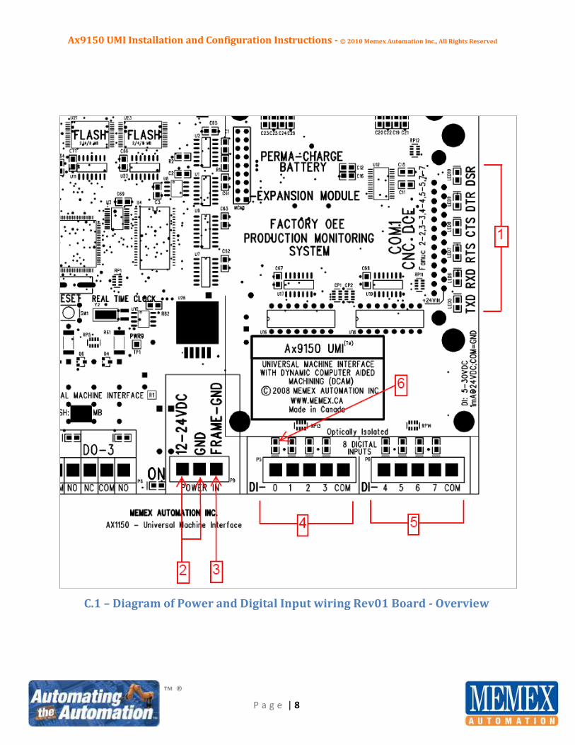
24 VDC from the COM1 CNC serial port on Pin 25 of the incoming female DB25 connector
attached to the CNC data port of the control (Fanuc Standard: see item 1, Diagram C.1, Page 8 or
item 1, Diagram C.2, Page 9).
External 12 – 24 VDC applied to the “POWER IN” pins located between the digital inputs and the
digital outputs (see item 2, Diagram C.1, Page 8 or item 2, Diagram C.2, Page 9).
Ax9150 UMI Installation and Configuration Instructions - © 2010 Memex Automation Inc., All Rights Reserved
™ ®
P a g e | 8
C.1 – Diagram of Power and Digital Input wiring Rev01 Board - Overview

Ax9150 UMI Installation and Configuration Instructions - © 2010 Memex Automation Inc., All Rights Reserved
™ ®
P a g e | 9
C.2 – Diagram of Power and Digital Input wiring Rev02 Board - Overview

Ax9150 UMI Installation and Configuration Instructions - © 2010 Memex Automation Inc., All Rights Reserved
™ ®
P a g e | 10
Section D - Determining the Machine Signals that are to be Tracked by
the Ax9150
There are many ways by which the Ax9150 can accept input data from a typical CNC machine. The
Ax9150 can accept a total of 32 input points, which can be a combination of the following:
Up to 8 hard-wired inputs (3-30 VDC; Sinking Rev01 - 2 groups of 4; Sinking or Sourcing Rev 02 -
4 groups of 2)
Up to 20 user-defined soft inputs, which can include DPRNT style commands via the CNC
machine’s serial data port
4 Default pre-defined modes, including:
o Maintenance mode – Scheduled
o Maintenance mode – Unscheduled
o Setup mode
o Production Hold mode
D.1 – Hard-wired Inputs
There are 8 hard-wired inputs available on the Ax9150, from DI0 – DI7 (see Diagram C.1, Page 8, items 4
and 5 - Rev01, or Diagram C.2, Page 9, items 6, 7, 8, 11, 12 and 13 - Rev02). It is mandatory to determine
what signals are to be tracked prior to attempting any wiring. Typically, the signals that account for the
majority of the machine’s downtime should be captured. On a typical CNC machine, the machine signals
that account for the most downtime are usually:
ESTOP
ALARM
M00
M01
FEEDHOLD
PROGRAM STOP
M30
Automatic Good Part Counting Input (optional)
Automatic Reject Part Counting Input (optional)
In addition, one input must be acquired from the machine to indicate when it is actually “INCYCLE”. It is
recommended that ESTOP be attached to input DI0 and Alarm be attached to DI1, but this is not an
absolute requirement as any hard-wired input can be wired to any input point from DI0 – DI7, in any
order.

Ax9150 UMI Installation and Configuration Instructions - © 2010 Memex Automation Inc., All Rights Reserved
™ ®
P a g e | 11
D.2 – User-Defined Inputs (Input 8 to Input 27)
There are 20 user-defined soft inputs that can be configured for the Ax9150. These are primarily used to
activate timers to track time from user input via the Mx2000 HOI terminal. In addition, these inputs can
include DPRNT style (Fanuc Standard) commands from the machine’s CNC serial data port. This option
would have had to have been previously purchased from the CNC machine vendor (if available) and
configured for use on your CNC control. Not all control manufacturers support these serial output
commands. They are typically utilized where a hard-wired input is not a possibility and usually require
the CNC program to be edited to include a Port Open command, followed by the syntax of the DPRNT
command, followed by a Port Close command. Memex has an entire suite of DNC software, including
FTP, Edit Plot, AxDNC and AxFMServer, that will automatically add these commands prior to the
program being downloaded to the CNC machine’s memory. This subject is covered in detail in another
Memex manual.
D.3 - Default Pre-Defined Modes
The Ax9150 has 4 pre-defined input modes that are pre-configured (I28-I31). These include Maintenance
Scheduled, Maintenance Unscheduled, Setup, and Production Hold modes. The use of these inputs will
be covered in Section H of this manual.
Section E - Wiring the Hard-wired Machine Signals on the Input Pins
As mentioned above, the Ax9150 accepts up to eight 3-30 VDC sinking or sourcing inputs on DI0 – DI7 in
two groups of four for the Rev01 board, or four groups of two for the Rev02 board. Please refer to
Diagram C.1, Page 8, items 4 and 5 for the Rev01 board, or Diagram C.2, Page 9, items 6. 7, 8, 11, 12 and
13 for the Rev02 board, for further clarification on the location of these inputs. For the Ax9150 Rev01
Board, the inputs are only accepted as a sinking type input, where the common is tied to 0 VDC (see
Diagram E.3, Page 13).
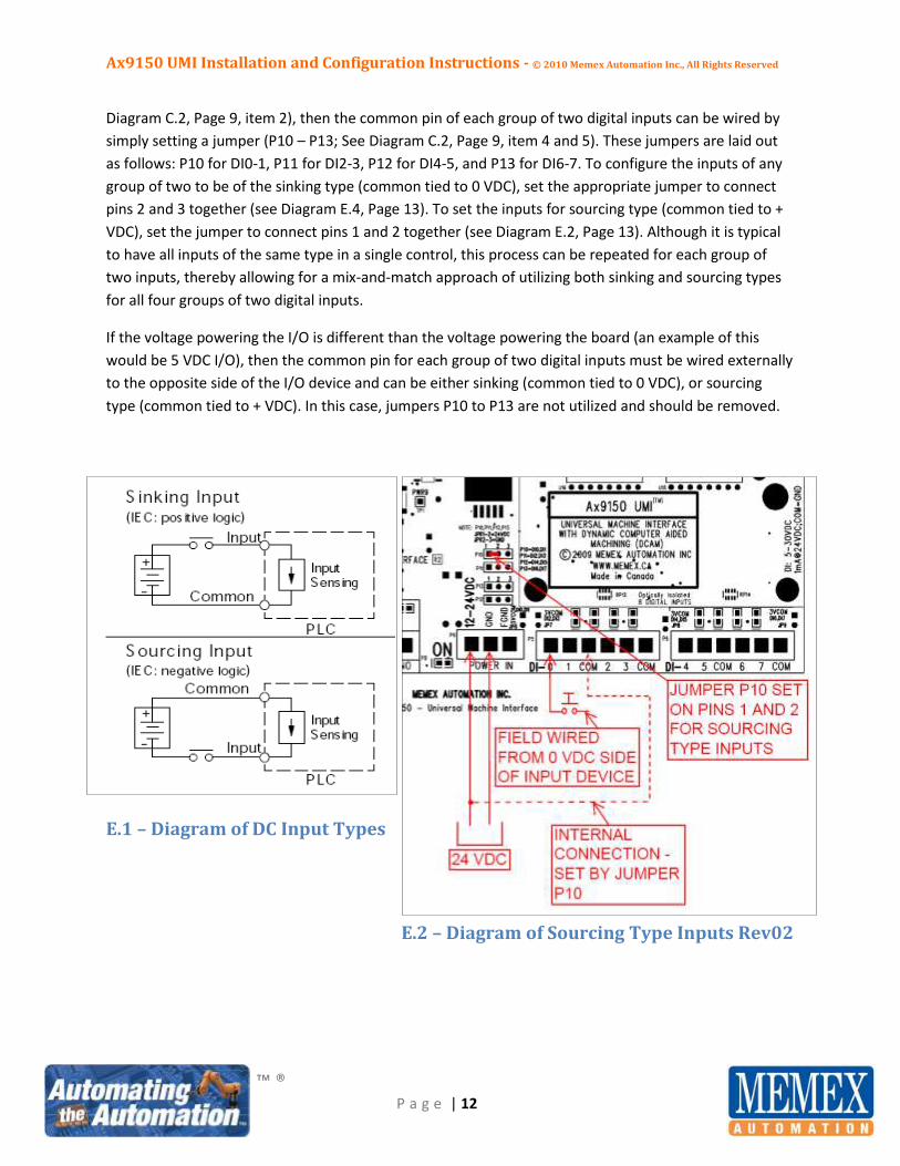
In the case of the Ax9150 Rev02 board, the first step to wiring the inputs is to determine whether they
will be of a sinking type (common tied to 0 VDC), or a sourcing type (common tied to + VDC). Please
refer to Diagram E.1 on Page 12 for clarification on the differences between the two styles of DC inputs.
If the inputs are 24 VDC and the board is powered by the CNC COM1 serial port (see Diagram C.2, Page
9, item 1), or the power source supplied to the inputs is the same as that utilized to power the board
(See
Ax9150 UMI Installation and Configuration Instructions - © 2010 Memex Automation Inc., All Rights Reserved
™ ®
P a g e | 12
Diagram C.2, Page 9, item 2), then the common pin of each group of two digital inputs can be wired by
simply setting a jumper (P10 – P13; See Diagram C.2, Page 9, item 4 and 5). These jumpers are laid out
as follows: P10 for DI0-1, P11 for DI2-3, P12 for DI4-5, and P13 for DI6-7. To configure the inputs of any
group of two to be of the sinking type (common tied to 0 VDC), set the appropriate jumper to connect
pins 2 and 3 together (see Diagram E.4, Page 13). To set the inputs for sourcing type (common tied to +
VDC), set the jumper to connect pins 1 and 2 together (see Diagram E.2, Page 13). Although it is typical
to have all inputs of the same type in a single control, this process can be repeated for each group of
two inputs, thereby allowing for a mix-and-match approach of utilizing both sinking and sourcing types
for all four groups of two digital inputs.
If the voltage powering the I/O is different than the voltage powering the board (an example of this
would be 5 VDC I/O), then the common pin for each group of two digital inputs must be wired externally
to the opposite side of the I/O device and can be either sinking (common tied to 0 VDC), or sourcing
type (common tied to + VDC). In this case, jumpers P10 to P13 are not utilized and should be removed.
E.1 – Diagram of DC Input Types
E.2 – Diagram of Sourcing Type Inputs Rev02
Ax9150 UMI Installation and Configuration Instructions - © 2010 Memex Automation Inc., All Rights Reserved
™ ®
P a g e | 13
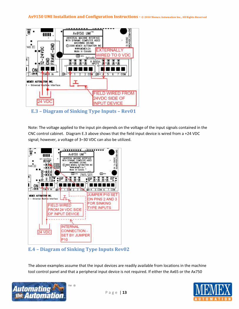
E.3 – Diagram of Sinking Type Inputs – Rev01
Note: The voltage applied to the input pin depends on the voltage of the input signals contained in the
CNC control cabinet. Diagram E.3 above shows that the field input device is wired from a +24 VDC
signal; however, a voltage of 3–30 VDC can also be utilized.
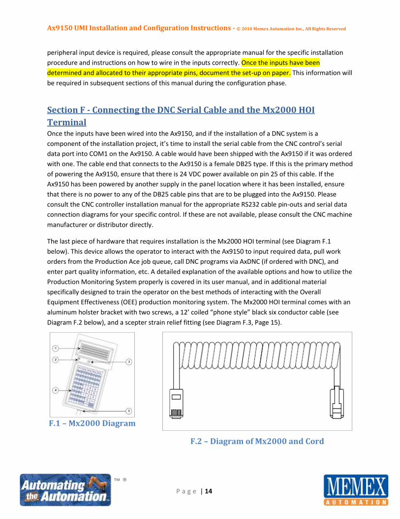
E.4 – Diagram of Sinking Type Inputs Rev02
The above examples assume that the input devices are readily available from locations in the machine
tool control panel and that a peripheral input device is not required. If either the Ax65 or the Ax750
Ax9150 UMI Installation and Configuration Instructions - © 2010 Memex Automation Inc., All Rights Reserved
™ ®
P a g e | 14
peripheral input device is required, please consult the appropriate manual for the specific installation
procedure and instructions on how to wire in the inputs correctly. Once the inputs have been
determined and allocated to their appropriate pins, document the set-up on paper. This information will
be required in subsequent sections of this manual during the configuration phase.
Section F - Connecting the DNC Serial Cable and the Mx2000 HOI
Terminal Once the inputs have been wired into the Ax9150, and if the installation of a DNC system is a
component of the installation project, it’s time to install the serial cable from the CNC control’s serial
data port into COM1 on the Ax9150. A cable would have been shipped with the Ax9150 if it was ordered
with one. The cable end that connects to the Ax9150 is a female DB25 type. If this is the primary method
of powering the Ax9150, ensure that there is 24 VDC power available on pin 25 of this cable. If the
Ax9150 has been powered by another supply in the panel location where it has been installed, ensure
that there is no power to any of the DB25 cable pins that are to be plugged into the Ax9150. Please
consult the CNC controller installation manual for the appropriate RS232 cable pin-outs and serial data
connection diagrams for your specific control. If these are not available, please consult the CNC machine
manufacturer or distributor directly.
The last piece of hardware that requires installation is the Mx2000 HOI terminal (see Diagram F.1
below). This device allows the operator to interact with the Ax9150 to input required data, pull work
orders from the Production Ace job queue, call DNC programs via AxDNC (if ordered with DNC), and
enter part quality information, etc. A detailed explanation of the available options and how to utilize the
Production Monitoring System properly is covered in its user manual, and in additional material
specifically designed to train the operator on the best methods of interacting with the Overall
Equipment Effectiveness (OEE) production monitoring system. The Mx2000 HOI terminal comes with an
aluminum holster bracket with two screws, a 12’ coiled “phone style” black six conductor cable (see
Diagram F.2 below), and a scepter strain relief fitting (see Diagram F.3, Page 15).
F.1 – Mx2000 Diagram
F.2 – Diagram of Mx2000 and Cord

Ax9150 UMI Installation and Configuration Instructions - © 2010 Memex Automation Inc., All Rights Reserved
™ ®
P a g e | 15
To mount the Mx2000 HOI terminal, remove the aluminum bracket and screws, and use a drill and the
two self-drilling and -tapping screws provided to secure the bracket to the side of the cabinet or
enclosure in prominent view of the operator. EXTREME CAUTION should be exercised here to ensure
that there are no internal wires located directly behind the location where the screws will enter the
cabinet, and that all metal particulate is prevented from contaminating the electronic devices within
the cabinet. To capture all metal particulate, lay out a protective blanket of clean rags or shop towels
on the cabinet floor and around sensitive electronic devices. The power should also be turned off for
this part of the installation to further reduce the risk of a short circuit due to flying metal particulate.
Failure to follow these instructions explicitly may result in irreparable damage to sensitive electronic
devices within the control cabinet. The CNC machine tool may be rendered inoperable, or worse, a fire
may start due to short-circuiting of these electronic devices.
A hole saw or stepped drill bit should be used to drill a 7/8” hole underneath the Mx2000 bracket into
which the scepter strain relief fitting is to be installed. EXTREME CAUTION should be exercised as
highlighted above to prevent any damage to the control cabinet contents. Once the hole is completed,
install the plastic base and use the lock nut provided to lock the base in place. Next, place the Mx2000 in
the holster and place the strain relief top retainer over the black cord. Choose the appropriate grommet
and slide it over the RJ12 end of the black cord.
From inside the control cabinet, pull the “phone style” cord (see Diagram F.2, Page 14) in so that there is
about six inches of cord that remains looped on the outside of the cabinet. Tighten the top retainer nut
until the sides of the grommet are squeezed around the phone cord so as to prevent any liquid from
entering the cabinet (see Diagram F.3 below).
F.3 – Scepter Strain Relief for Mx2000 Installation Diagram
If the Ax9150 is located inside the control cabinet, plug the RJ12 connector into the plug marked “TERM
RJ12” located in the top right of the Ax9150 next to the “WAND COM4” port.

Ax9150 UMI Installation and Configuration Instructions - © 2010 Memex Automation Inc., All Rights Reserved
™ ®
P a g e | 16
If the Ax9150 is not located inside the control cabinet, and a low capacitance (“LowCap”) six wire multi-
conductor cable (raw cable and DB9 M and F connectors can be purchased from Memex, see Diagram
F.5, below) was pulled to extend this connection, ensure that it is terminated by soldering in accordance
with the following instructions:
DB9F Female connection at the location where the Ax9150 is located.
DB9M Male connection at the location where the Mx2000 terminal is located.
Use one RJ12 to DB9F adapter on the end where the Mx2000 terminal is to be located. These
can be purchased from Memex (see Diagrams F.4 and F.6, below).
Terminate via solder connection (assumes Memex-supplied LowCap cable is used).
o Pin 9 to Pin 9, ORANGE
o Pin 8 to Pin 8, BLUE
o Pin 7 to Pin 7, GREEN
o Pin 5 to Pin 5, ORANGE WHITE
o Pin 3 to Pin 3, BLUE WHITE
o Pin 2 to Pin 2, GREEN WHITE
o Connect the shield (drain) wire to Pin 1 on the Ax9150 side (DB9F) only.
F.4 – RJ12 to DB9 Adapter Diagram
F.5 – DB9 Pin-outs Diagram
F.6 – Diagram of the RJ12 to DB9 Pin-outs

Ax9150 UMI Installation and Configuration Instructions - © 2010 Memex Automation Inc., All Rights Reserved
™ ®
P a g e | 17
In the control cabinet where the Mx2000 has been installed, connect the DB9M end to the RJ12 to DB9F
adapter end, and secure with a crossing-style cable tie connection. Plug the Mx2000 RJ12 into the RJ12
end of the adapter.
In the control cabinet where the Ax9150 has been installed, connect and secure with screws the DB9F
connection to the serial port marked “TERM DTE COM3”.
Section G - Connecting the Ethernet Cable
The straight-through CAT5 ethernet cable should be run from the plant switch to the location of the
Ax9150 board. The RJ45 connector on the end of the ethernet cable should be tested to ensure that the
cable is sound and that all required connections are completed correctly. The RJ45 connector plugs into
the RJ45 socket located on the Ax2200 ethernet module attached to the Ax9150.
This concludes the hardware install portion of the Ax9150 installation. Please refer to sections H-M of
this manual for instructions on how to set up and configure the Ax9150 UMI utilizing Memex’s AxConfig
software suite.

Ax9150 UMI Installation and Configuration Instructions - © 2010 Memex Automation Inc., All Rights Reserved
™ ®
P a g e | 18
Section H - Connecting to the Network via AxConfig
Prior to connecting the Ax9150 UMI to the ethernet network and configuring it to collect data, it is
important to acquire and write down on paper six key pieces of information that will be required during
the set-up process via AxConfig. These pieces of information are:
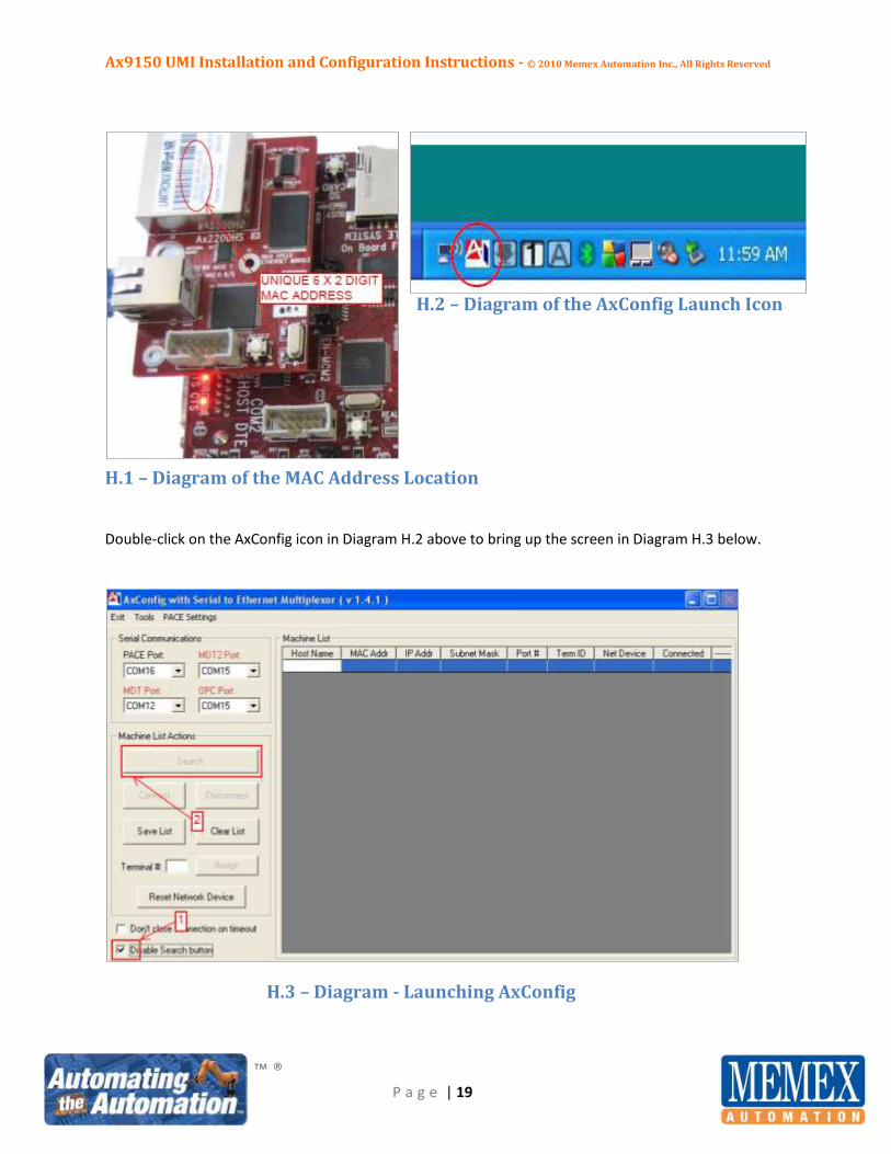
1. The unique MAC address of the Ax2200 ethernet module connected to the Ax9150. This address
is a series of 6 sets of 2 characters separated by hyphens, and is located on the top of the
Lantronix ethernet module (see Diagram H.1, Page 19) - Eg. 00-20-4A-9F-FE-32
2. A unique three digit numeric terminal ID that differs from any other Ax9150 already installed on
the network. - Eg. 088 (this can be any number from 001 to 899).
3. A unique IP address that differs from that of any other device currently installed on the internal
TCP/IP ethernet network. - Eg. 10.10.1.242
4. A subnet mask that is related to the TCP/IP address - Eg. 255.255.255.0
5. A default gateway that is related to the TCP/IP address - Eg. 10.10.1.1
6. An alpha-numeric or numeric name that will show in the Host Name Column of AxConfig. - Eg.
MACSIM01
The above sample information (prefixed with Eg. and shown in bold) will be used throughout the
remainder of this manual to aid in visualizing an actual Ax9150 set-up. Items 2, 3, 4 and 5 should be
available from your corporate network administrator.
It is important to ensure that AxConfig has been installed on the server that will collect the OEE data.
The latest version of AxConfig can be downloaded from support.memex.ca/files. It is good practice to
check with our support site to ensure that the latest version of AxConfig is utilized at the time of the
installation, as AxConfig is updated regularly to incorporate the latest functions and features.
To install the AxConfig software, simply click on the Setup.exe program and follow the instructions and
screen prompts. Ensure that the AxConfig files are installed in the directory C:\Program Files\AxConfig.
Once installation has completed, reboot the server or computer. AxConfig should automatically start
and minimize itself in the program tray at the bottom right corner of the screen (see Diagram H.2, Page
19).
Ax9150 UMI Installation and Configuration Instructions - © 2010 Memex Automation Inc., All Rights Reserved
™ ®
P a g e | 19
H.2 – Diagram of the AxConfig Launch Icon
H.1 – Diagram of the MAC Address Location
Double-click on the AxConfig icon in Diagram H.2 above to bring up the screen in Diagram H.3 below.
H.3 – Diagram - Launching AxConfig
Ax9150 UMI Installation and Configuration Instructions - © 2010 Memex Automation Inc., All Rights Reserved
™ ®
P a g e | 20
To search for the Ax9150, remove the check mark in the “Disable Search button” box at the bottom of
the screen (see Diagram H.3, Page 19, item 1). A “Search” button will become visible (see Diagram H.3,
Page 19, item 2). Click on the “Search” button to bring up the screen shown in Diagram H.4 below.
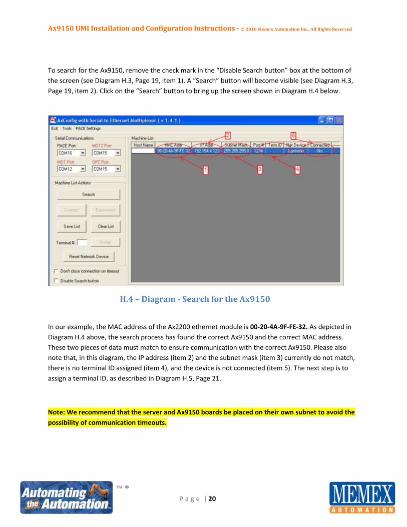
H.4 – Diagram - Search for the Ax9150
In our example, the MAC address of the Ax2200 ethernet module is 00-20-4A-9F-FE-32. As depicted in
Diagram H.4 above, the search process has found the correct Ax9150 and the correct MAC address.
These two pieces of data must match to ensure communication with the correct Ax9150. Please also
note that, in this diagram, the IP address (item 2) and the subnet mask (item 3) currently do not match,
there is no terminal ID assigned (item 4), and the device is not connected (item 5). The next step is to
assign a terminal ID, as described in Diagram H.5, Page 21.
Note: We recommend that the server and Ax9150 boards be placed on their own subnet to avoid the
possibility of communication timeouts.
Ax9150 UMI Installation and Configuration Instructions - © 2010 Memex Automation Inc., All Rights Reserved
™ ®
P a g e | 21
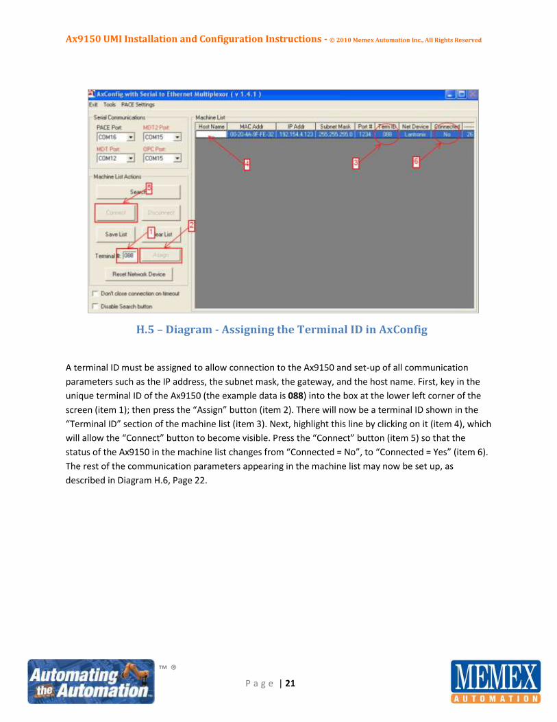
H.5 – Diagram - Assigning the Terminal ID in AxConfig
A terminal ID must be assigned to allow connection to the Ax9150 and set-up of all communication
parameters such as the IP address, the subnet mask, the gateway, and the host name. First, key in the
unique terminal ID of the Ax9150 (the example data is 088) into the box at the lower left corner of the
screen (item 1); then press the “Assign” button (item 2). There will now be a terminal ID shown in the
“Terminal ID” section of the machine list (item 3). Next, highlight this line by clicking on it (item 4), which
will allow the “Connect” button to become visible. Press the “Connect” button (item 5) so that the
status of the Ax9150 in the machine list changes from “Connected = No”, to “Connected = Yes” (item 6).
The rest of the communication parameters appearing in the machine list may now be set up, as
described in Diagram H.6, Page 22.

Ax9150 UMI Installation and Configuration Instructions - © 2010 Memex Automation Inc., All Rights Reserved
™ ®
P a g e | 22
H.6 – Diagram - Connection Established to the Network
With the Ax9150 shown as “Connected = Yes”, double-click on the line in the machine list to bring up a
dialog box that allows a choice between “I/O Setup” and “Communications Setup”. Click on the
“Communications Setup” button to launch the window depicted in Diagram H.7 on Page 23.
Ax9150 UMI Installation and Configuration Instructions - © 2010 Memex Automation Inc., All Rights Reserved
™ ®
P a g e | 23
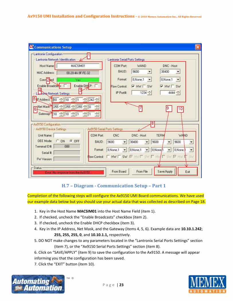
H.7 – Diagram - Communication Setup – Part 1
Completion of the following steps will configure the Ax9150 UMI Board communications. We have used
our example data below but you should use your actual data that was collected as described on Page 18.
1. Key in the Host Name MACSIM01 into the Host Name Field (item 1).
2. If checked, uncheck the “Enable Broadcasts” checkbox (item 2).
3. If checked, uncheck the Enable DHCP checkbox (item 3).
4. Key in the IP Address, Net Mask, and the Gateway (items 4, 5, 6). Example data are 10.10.1.242;
255, 255, 255, 0, and 10.10.1.1, respectively.
5. DO NOT make changes to any parameters located in the “Lantronix Serial Ports Settings” section
(item 7), or the “Ax9150 Serial Ports Settings” section (item 8).
6. Click on “SAVE/APPLY” (item 9) to save the configuration to the Ax9150. A message will appear
informing you that the configuration has been saved.
7. Click the “EXIT” button (item 10).
Ax9150 UMI Installation and Configuration Instructions - © 2010 Memex Automation Inc., All Rights Reserved
™ ®
P a g e | 24
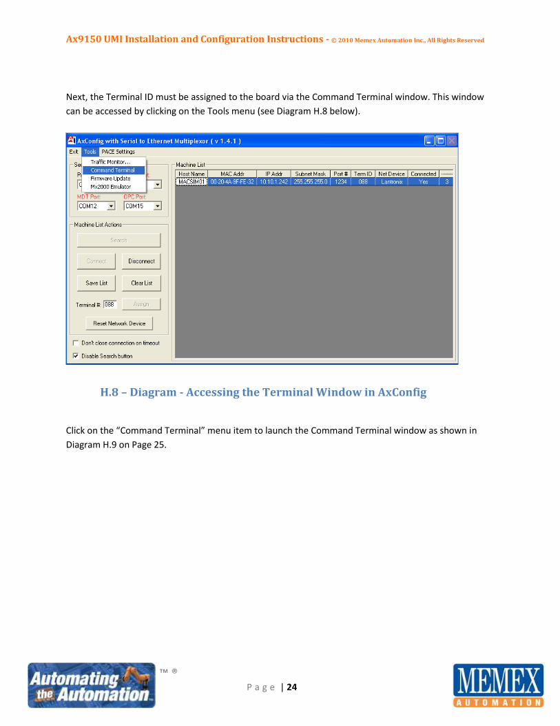
Next, the Terminal ID must be assigned to the board via the Command Terminal window. This window
can be accessed by clicking on the Tools menu (see Diagram H.8 below).
.
H.8 – Diagram - Accessing the Terminal Window in AxConfig
Click on the “Command Terminal” menu item to launch the Command Terminal window as shown in
Diagram H.9 on Page 25.
Ax9150 UMI Installation and Configuration Instructions - © 2010 Memex Automation Inc., All Rights Reserved
™ ®
P a g e | 25
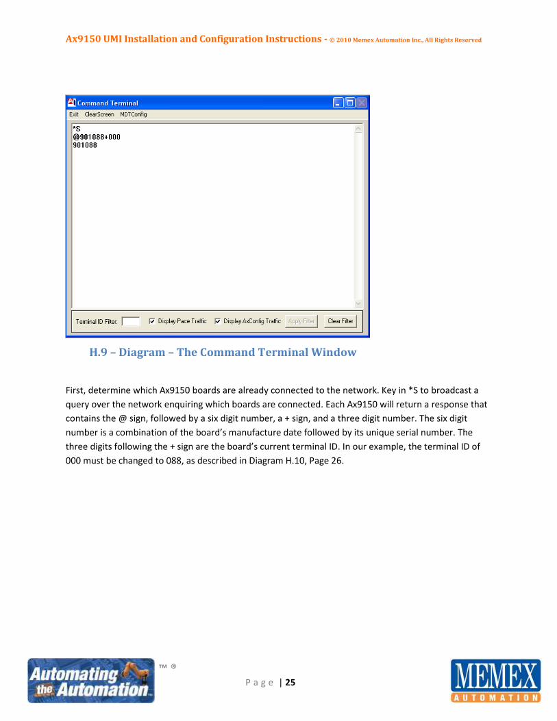
H.9 – Diagram – The Command Terminal Window
First, determine which Ax9150 boards are already connected to the network. Key in *S to broadcast a
query over the network enquiring which boards are connected. Each Ax9150 will return a response that
contains the @ sign, followed by a six digit number, a + sign, and a three digit number. The six digit
number is a combination of the board’s manufacture date followed by its unique serial number. The
three digits following the + sign are the board’s current terminal ID. In our example, the terminal ID of
000 must be changed to 088, as described in Diagram H.10, Page 26.
Ax9150 UMI Installation and Configuration Instructions - © 2010 Memex Automation Inc., All Rights Reserved
™ ®
P a g e | 26
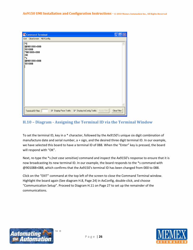
H.10 – Diagram - Assigning the Terminal ID via the Terminal Window
To set the terminal ID, key in a * character, followed by the Ax9150’s unique six digit combination of
manufacture date and serial number, a + sign, and the desired three digit terminal ID. In our example,
we have selected this board to have a terminal ID of 088. When the “Enter” key is pressed, the board
will respond with “OK”.
Next, re-type the *s (not case sensitive) command and inspect the Ax9150’s response to ensure that it is
now broadcasting its new terminal ID. In our example, the board responds to the *s command with
@901088+088, which confirms that the Ax9150’s terminal ID has been changed from 000 to 088.
Click on the “EXIT” command at the top left of the screen to close the Command Terminal window.
Highlight the board again (See diagram H.8, Page 24) in AxConfig, double-click, and choose
“Communication Setup”. Proceed to Diagram H.11 on Page 27 to set up the remainder of the
communications.

Ax9150 UMI Installation and Configuration Instructions - © 2010 Memex Automation Inc., All Rights Reserved
™ ®
P a g e | 27
H.11 – Diagram - Ax9150 Communication Setup - Part 2
1. Key in the desired Unit Name that should be displayed on the Mx2000 HOI terminal. If no name
has been provided, the Host Name can be substituted (item 1).
2. Ensure that OEE mode is selected to “OFF” (item 2).
3. Click on “SAVE/APPLY” (item 4) to save the configuration to the Ax9150. A message will appear
in the Status bar informing you that the configuration has been saved (item 3).
4. Click the “EXIT” button (item 5).

Ax9150 UMI Installation and Configuration Instructions - © 2010 Memex Automation Inc., All Rights Reserved
™ ®
P a g e | 28
The Machine List screen in AxConfig should now look like Diagram H.12 below.
H.12 – Diagram - Communication Setup Completed
The Ax9150 has now been successfully configured for communication and is attached to the network.
The Host Name (item 1), the IP Address (item 2), and the Subnet Mask (item 3) have all been changed to
their correct values as per our example data. The board is successfully connected to the network as
shown in the Machine List under “Connected = Yes” (item 4). Click on the “Disable Search button” box
located at the bottom left corner of the screen to prevent additional changes (item 5).
To define the inputs, timers for OEE data collection, and the required ladder rungs to condition the input
signals to respond correctly, please advance to Section I on Page 29.

Ax9150 UMI Installation and Configuration Instructions - © 2010 Memex Automation Inc., All Rights Reserved
™ ®
P a g e | 29
Section I - Configuring All Input Names (Hard-wired, User-defined, and
Soft I/O)
Now that you have successfully physically installed the 8 hard-wired inputs, connected the board via
ethernet, configured the communications, and brought the Ax9150 UMI board online, you are ready for
the set-up and signal conditioning of all inputs required to collect the downtime data associated with
your CNC machining centre. As described above in Section D on Page 10, there are three methods by
which the Ax9150 can accept input stimuli. For review purposes, they are:
Up to 8 hard-wired inputs (3-30 VDC, sinking or sourcing, 4 groups of 2)
Up to 20 user-defined soft inputs, which include DPRNT style commands via the CNC machine’s
serial data port
4 Default pre-defined (modes), including:
o Maintenance mode – Scheduled
o Maintenance mode – Unscheduled
o Set-up mode
o Production Hold mode
The purpose of these inputs is to drive timers to collect data when the CNC machine is not “INCYCLE”.
Memex supports up to 20 timers that can collect downtime information and report it to the Production
Ace production monitoring system, providing a vital component of the OEE calculation. The inputs can
be either “Normally Open” or “Normally Closed”. They can also be hard-wired, soft inputs such as
DPRNT commands, or generated from the HOI terminal by the operator. Memex currently supports 4
modes from the HOI terminal, and up to 7 user-defined downtime reason codes that can appear when
the machine is in an IDLE state. An IDLE state is defined as not INCYCLE and not in any one of the up to 8
hard-wired states that can be physically collected on the input pins of the Ax9150. The hard-wired
inputs can be in a solid state or of a flashing type. AxConfig contains a simple PLC-style ladder generator
program that allows you to condition and program virtually all states and their associated combinations
to arrive at the correct overall state. This overall state then drives up to 20 timers that collect the
downtime information required to effectively and accurately calculate the machine utilization
component of OEE.
Ax9150 UMI Installation and Configuration Instructions - © 2010 Memex Automation Inc., All Rights Reserved
™ ®
P a g e | 30
The process to configure the ladder starts with acquiring the answers to the following questions:
What hard-wired inputs are wired to which input pins? (Refer to the list generated when the
inputs were wired in (Section E, top of Page14.) Each of these input pins usually drives a
downtime timer (with the exception of INCYCLE).
What are your 7 user-defined downtime reason codes? Each of these inputs also drives a
downtime timer and can be used to solicit operator input when the machine is in an IDLE state.
What soft inputs will be collected by DPRNT instructions or similar method? These inputs usually
substitute for hard-wired inputs that are simply not available. An example would be the CNC M
code, M30.
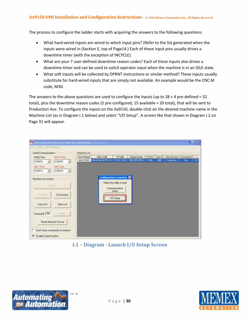
The answers to the above questions are used to configure the inputs (up to 28 + 4 pre-defined = 32
total), plus the downtime reason codes (5 pre-configured, 15 available = 20 total), that will be sent to
Production Ace. To configure the inputs on the Ax9150, double-click on the desired machine name in the
Machine List (as in Diagram I.1 below) and select “I/O Setup”. A screen like that shown in Diagram I.2 on
Page 31 will appear.
I.1 – Diagram - Launch I/O Setup Screen
Ax9150 UMI Installation and Configuration Instructions - © 2010 Memex Automation Inc., All Rights Reserved
™ ®
P a g e | 31
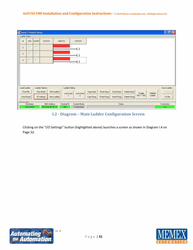
I.2 - Diagram – Main Ladder Configuration Screen
Clicking on the “I/O Settings” button (highlighted above) launches a screen as shown in Diagram I.4 on
Page 32.
Ax9150 UMI Installation and Configuration Instructions - © 2010 Memex Automation Inc., All Rights Reserved
™ ®
P a g e | 32
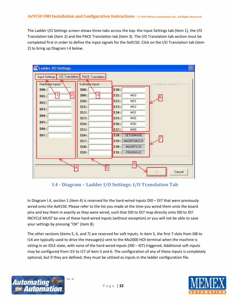
The Ladder I/O Settings screen shows three tabs across the top: the Input Settings tab (item 1), the I/O
Translation tab (item 2) and the PACE Translation tab (item 3). The I/O Translation tab section must be
completed first in order to define the input signals for the Ax9150. Click on the I/O Translation tab (item
2) to bring up Diagram I.4 below.
I.4 - Diagram – Ladder I/O Settings: I/O Translation Tab
In Diagram I.4, section 1 (item 4) is reserved for the hard-wired inputs DI0 – DI7 that were previously
wired onto the Ax9150. Please refer to the list you made at the time you wired them onto the board
pins and key them in exactly as they were wired, such that DI0 to DI7 map directly onto I00 to I07.
INCYCLE MUST be one of these hard-wired inputs (without exception) or you will not be able to save
your settings by pressing “OK” (item 8).
The other sections (items 5, 6, and 7) are reserved for soft inputs. In item 5, the first 7 slots from I08 to
I14 are typically used to drive the message(s) sent to the Mx2000 HOI terminal when the machine is
sitting in an IDLE state, with none of the hard-wired inputs (I00 – I07) triggered. Additional soft inputs
may be configured from I15 to I27 of item 5 and 6. The configuration of any of these inputs is completely
optional, but if they are defined, they must be utilized as inputs in the ladder configuration file.

Ax9150 UMI Installation and Configuration Instructions - © 2010 Memex Automation Inc., All Rights Reserved
™ ®
P a g e | 33
Once the I/O Translation tab has been completed, you may proceed to the Pace Translation tab, as
shown in Diagram I.5 below. Click on this tab to see the Pace Translation screen or press “OK” to return
to the main ladder configuration screen.
I.5 – Diagram – Ladder I/O Settings: PACE Translation Tab
Diagram I.5 above shows the “PACE Translation” tab (item 3). This tab is used for the configuration of
the downtime reason codes that will be sent to, and tracked, by the Production Ace production
monitoring system. Section 1 (item 4) is reserved for configuring the timers associated with hard-wired
inputs. Examples include ESTOP, ALARM, M00, M01, FEEDHOLD, M30, etc. Section 2 (item 5) is used to
configure the 7 user-defined downtime reason codes that will be presented to the operator for selection
when the machine enters the IDLE state. Examples include CHIPS, MEETING, LUNCHBRK, NO_MATERL,
NO_OPERATR. Section 3 (item 6) is pre-configured and cannot be changed. It should be noted that a
ladder rung must be written for every defined timer (including the pre-defined slots T16 - T20). In the
absence of such ladder rungs, the configuration file cannot be validated and therefore will not download
to the Ax9150. Section 4 (item 7) is reserved for the definition of up to 20 reject/rework codes that will
be displayed to the operator when a rejected part is counted at the Mx2000 HOI terminal by the
operator. These are fully configurable and can be different for each machine.

Ax9150 UMI Installation and Configuration Instructions - © 2010 Memex Automation Inc., All Rights Reserved
™ ®
P a g e | 34
Once the I/O Translation and PACE Translation tabs have been completed, click on the “Input Settings”
tab of the Ladder I/O Settings screen to bring you to the screen depicted in Diagram I.6 below.
I.6 – Diagram – Input Settings Tab
This screen allows the conditioning of the input signals to accommodate flashing inputs (items 1, 2, 3),
or to set one of the hard-wired inputs to automatically count good parts (item 4), or to set one of the
hard-wired inputs to automatically count rejected parts (item 5). The use of automatic parts or reject
counting is usually reserved for high volume production environments and, in the case of rejects,
requires some type of automatic gauging system to quickly determine that a part is, in fact, a rejected
part.
In the case of flashing signals, the use of item 1 or 2 of Diagram I.6 above depends on the type of de-
bounce required. Item 3 is the amount of time the flashing state is de-bounced (ignored) with the input
being artificially held high or low for the time set on the slider bar. Typically, an input may be in one
steady state when the machine is in one mode, and flash when the machine is in another mode. When
this signal is utilized as an input to the ladder, problems can arise if the signal is not correctly de-
bounced first. A good example is the flashing of “INCYCLE” when the machine is in a FEEDHOLD state.
The de-bounce settings also depend on whether the input signal is sinking or sourcing, and whether you
need to de-bounce the leading or trailing edge (Low or High). Please refer to Diagram I.7, Page 35 for the
correct use of de-bounce settings.
Ax9150 UMI Installation and Configuration Instructions - © 2010 Memex Automation Inc., All Rights Reserved
™ ®
P a g e | 35
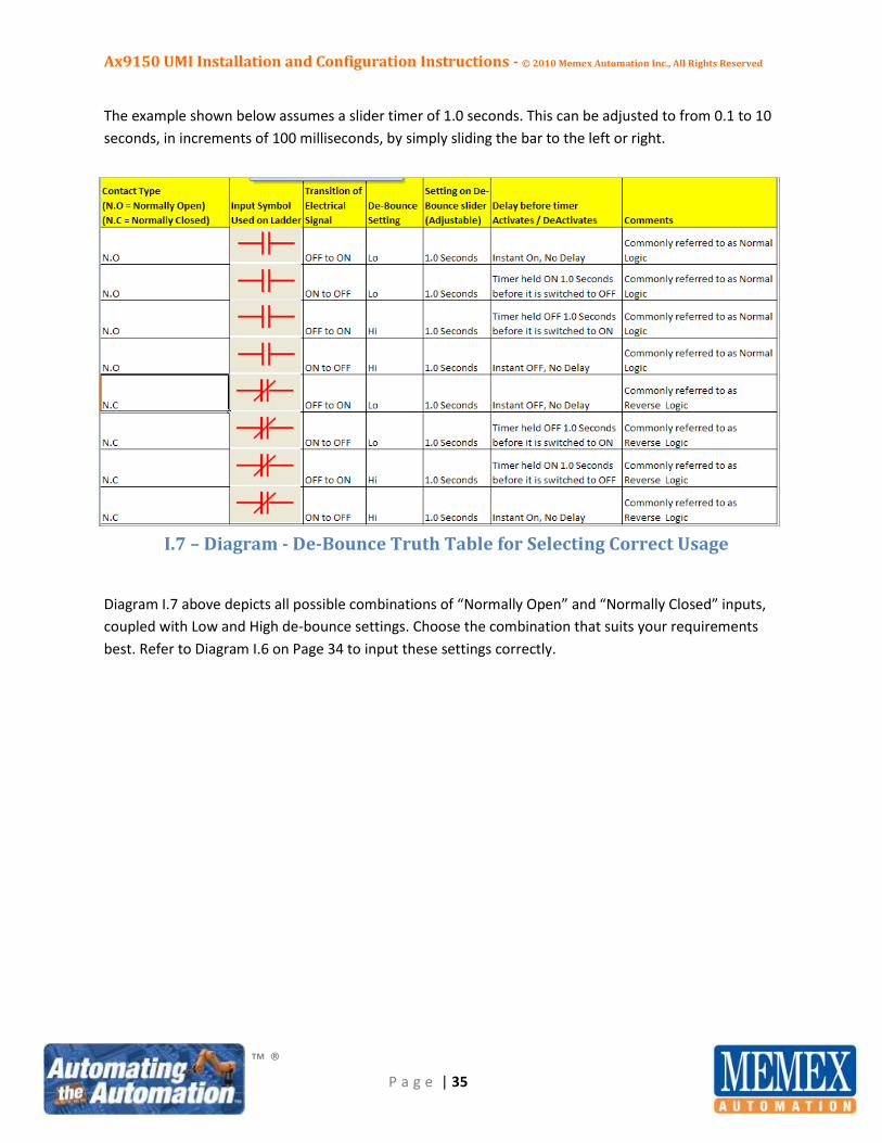
The example shown below assumes a slider timer of 1.0 seconds. This can be adjusted to from 0.1 to 10
seconds, in increments of 100 milliseconds, by simply sliding the bar to the left or right.
I.7 – Diagram - De-Bounce Truth Table for Selecting Correct Usage
Diagram I.7 above depicts all possible combinations of “Normally Open” and “Normally Closed” inputs,
coupled with Low and High de-bounce settings. Choose the combination that suits your requirements
best. Refer to Diagram I.6 on Page 34 to input these settings correctly.

Ax9150 UMI Installation and Configuration Instructions - © 2010 Memex Automation Inc., All Rights Reserved
™ ®
P a g e | 36
Section J - Truth Table Development Utilizing the Mx2000 HOI Terminal
After all the inputs have been wired to the Ax9150 and configured in AxConfig, and the downtime timers
have been defined, it’s time to collect the required data from the CNC machine tool to build the ladder
style configuration file. In Appendix A of this manual (Page 62), you will find a useful tool to assist in
collecting the data required to complete this vital step.
Appendix A is a simple Truth Table spreadsheet that allows for the definition of the hard-wired inputs,
the definition of the timers configured in the previous step, and the collection of their actual states
when these modes of operation are triggered on the CNC Control by the operator.
The process is as follows:
1. Obtain the Appendix A form and fill out the node name and date at the top left. If there are
multiple machines to configure, make a photocopy of this sheet for each machine.
2. Across the top of the sheet, fill in the hard-wired inputs that are wired on pins DI0 – DI7 (taken
from the I/O Translation tab as shown in Diagram I.4, Page 32).
3. Down the left hand column of the sheet, fill in the downtime timers (machine modes - T1 to T8
only; taken from the PACE Translation tab as shown in Diagram I.5, Page 33).
4. Follow the steps outlined below to place the Mx2000 HOI terminal in the mode needed to
monitor the digital input status.
5. Have the operator place the machine in each mode identified in Step 3 above and write down
on the sheet the 0 and 1 combination opposite this timer/mode, starting from left to right
across the page.
6. Repeat Step 5 until the data for all machine modes have been collected and transcribed to the
Truth Table form. Ensure that you also collect data for the machine when it is in an INCYCLE
state, and when it is in an IDLE state. It is extremely important to capture the EXACT responses
the machine sends to the digital inputs because these data are required for the next step of the
configuration process, the configuration of the ladder style file to be downloaded to the Ax9150.
The next few pages cover an example of the above process, complete with screen shots depicting an
actual machine set-up. This example will also be utilized in Section K when the configuration file for the
Ax9150 is created and subsequently downloaded.
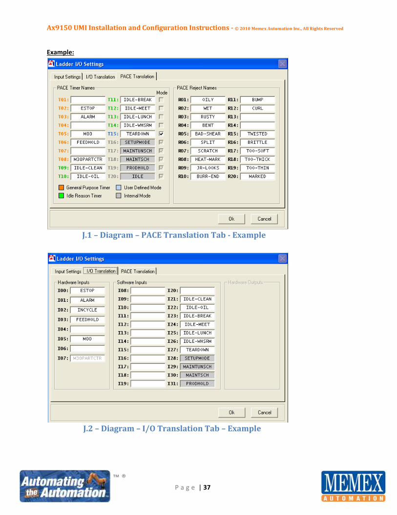
Diagrams J.1 and J.2 on Page 37 show the PACE Translation tab and the I/O Translation tab as they relate
to our working example. Diagram J.3 on page 38 shows the mapping of these data points to the Truth
Table form.
Ax9150 UMI Installation and Configuration Instructions - © 2010 Memex Automation Inc., All Rights Reserved
™ ®
P a g e | 37
Example:
J.1 – Diagram – PACE Translation Tab - Example
J.2 – Diagram – I/O Translation Tab – Example

Ax9150 UMI Installation and Configuration Instructions - © 2010 Memex Automation Inc., All Rights Reserved
™ ®
P a g e | 38
J.3 – Diagram – Truth Table Mapping From AxConfig – Example
In Diagram J.3 above, the data from the PACE translation tab in Diagram J.1 and the data from the I/O
Translation tab in Diagram J.2 (both on Page 37) have been transcribed to the Truth Table form to
prepare for the next step in the configuration process.
The next steps in our example are to place the Mx2000 in digital input monitor mode, have the operator
place the machine into ESTOP, ALARM, M00, FEEDHOLD, and M30 modes, and transcribe the Mx2000
screen contents to the Truth Table form. This information will then be utilized to develop the ladder
style configuration file in AxConfig that will be downloaded to the Ax9150.
Ax9150 UMI Installation and Configuration Instructions - © 2010 Memex Automation Inc., All Rights Reserved
™ ®
P a g e | 39
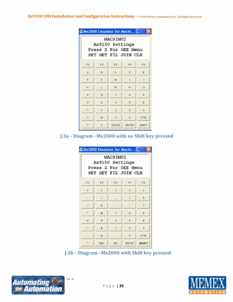
J.3a – Diagram –Mx2000 with no Shift key pressed
J.3b – Diagram –Mx2000 with Shift key pressed

Ax9150 UMI Installation and Configuration Instructions - © 2010 Memex Automation Inc., All Rights Reserved
™ ®
P a g e | 40
J.4 - Navigating to the DI Status Window with the Mx2000
Depicted below are screen captures from the Mx2000 HOI. Only the display area, plus the first row of
“F” keys are shown. For a complete view of the entire terminal layout, with and without the shift key
pressed, please see Diagram J.3a and J.3b on Page 39. To place the Mx2000 in digital input monitor
mode, follow these instructions:
1. When at the main menu (shown in Diagram J.4a below), press the F1 key. Proceed to step 2.
J.4a - Diagram– Mx2000 Main Menu
2. A screen will appear as shown in Diagram J.4b below. Press the numeric 4 key (bottom right
section of the handheld). Proceed to step 3.
J.4b – Diagram – Mx2000 Configuration Menu
Ax9150 UMI Installation and Configuration Instructions - © 2010 Memex Automation Inc., All Rights Reserved
™ ®
P a g e | 41
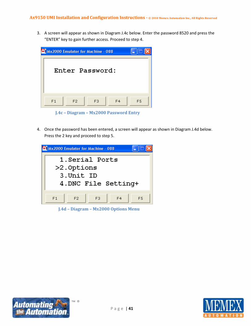
3. A screen will appear as shown in Diagram J.4c below. Enter the password 8520 and press the
“ENTER” key to gain further access. Proceed to step 4.
J.4c – Diagram – Mx2000 Password Entry
4. Once the password has been entered, a screen will appear as shown in Diagram J.4d below.
Press the 2 key and proceed to step 5.
J.4d – Diagram – Mx2000 Options Menu
Ax9150 UMI Installation and Configuration Instructions - © 2010 Memex Automation Inc., All Rights Reserved
™ ®
P a g e | 42
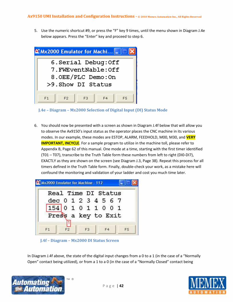
5. Use the numeric shortcut #9, or press the “F” key 9 times, until the menu shown in Diagram J.4e
below appears. Press the “Enter” key and proceed to step 6.
J.4e – Diagram – Mx2000 Selection of Digital Input (DI) Status Mode
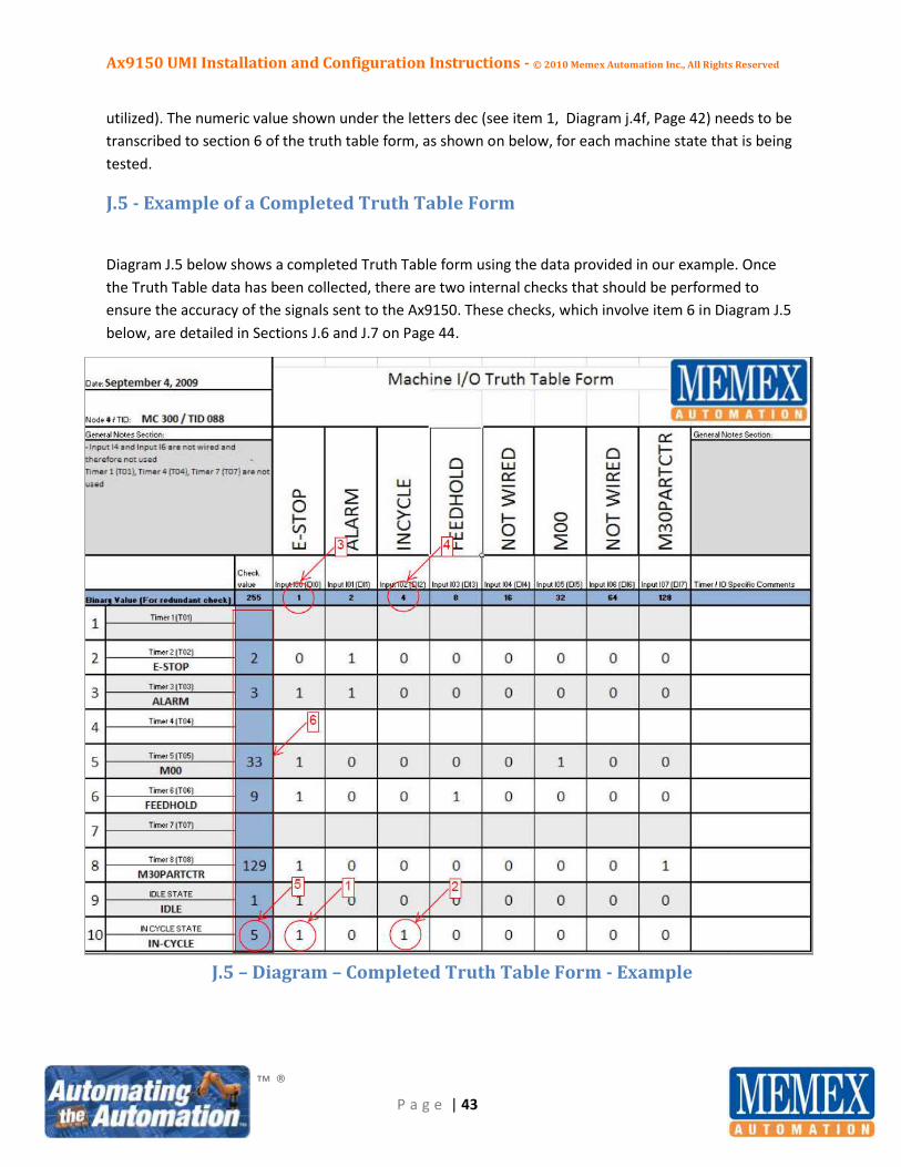
6. You should now be presented with a screen as shown in Diagram J.4f below that will allow you
to observe the Ax9150’s input status as the operator places the CNC machine in its various
modes. In our example, these modes are ESTOP, ALARM, FEEDHOLD, M00, M30, and VERY
IMPORTANT, INCYCLE. For a sample program to utilize in the machine toll, please refer to
Appendix B, Page 62 of this manual. One mode at a time, starting with the first timer identified
(T01 – T07), transcribe to the Truth Table form these numbers from left to right (DI0-DI7),
EXACTLY as they are shown on the screen (see Diagram J.3, Page 38). Repeat this process for all
timers defined in the Truth Table form. Finally, double-check your work, as a mistake here will
confound the monitoring and validation of your ladder and cost you much time later.
J.4f – Diagram – Mx2000 DI Status Screen
In Diagram J.4f above, the state of the digital input changes from a 0 to a 1 (in the case of a “Normally
Open” contact being utilized), or from a 1 to a 0 (in the case of a “Normally Closed” contact being
Ax9150 UMI Installation and Configuration Instructions - © 2010 Memex Automation Inc., All Rights Reserved
™ ®
P a g e | 43
utilized). The numeric value shown under the letters dec (see item 1, Diagram j.4f, Page 42) needs to be
transcribed to section 6 of the truth table form, as shown on below, for each machine state that is being
tested.
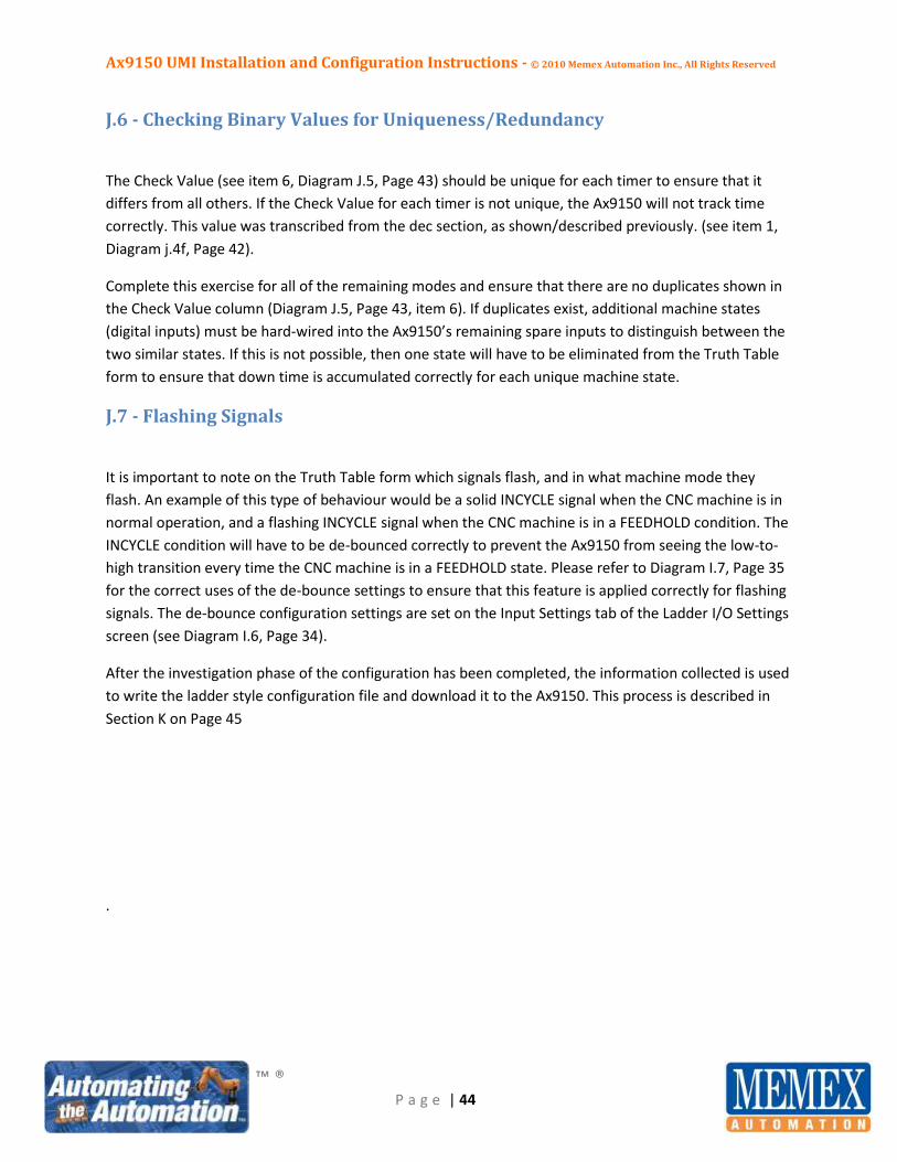
J.5 - Example of a Completed Truth Table Form
Diagram J.5 below shows a completed Truth Table form using the data provided in our example. Once
the Truth Table data has been collected, there are two internal checks that should be performed to
ensure the accuracy of the signals sent to the Ax9150. These checks, which involve item 6 in Diagram J.5
below, are detailed in Sections J.6 and J.7 on Page 44.
J.5 – Diagram – Completed Truth Table Form - Example
Ax9150 UMI Installation and Configuration Instructions - © 2010 Memex Automation Inc., All Rights Reserved
™ ®
P a g e | 44
J.6 - Checking Binary Values for Uniqueness/Redundancy
The Check Value (see item 6, Diagram J.5, Page 43) should be unique for each timer to ensure that it
differs from all others. If the Check Value for each timer is not unique, the Ax9150 will not track time
correctly. This value was transcribed from the dec section, as shown/described previously. (see item 1,
Diagram j.4f, Page 42).
Complete this exercise for all of the remaining modes and ensure that there are no duplicates shown in
the Check Value column (Diagram J.5, Page 43, item 6). If duplicates exist, additional machine states
(digital inputs) must be hard-wired into the Ax9150’s remaining spare inputs to distinguish between the
two similar states. If this is not possible, then one state will have to be eliminated from the Truth Table
form to ensure that down time is accumulated correctly for each unique machine state.
J.7 - Flashing Signals
It is important to note on the Truth Table form which signals flash, and in what machine mode they
flash. An example of this type of behaviour would be a solid INCYCLE signal when the CNC machine is in
normal operation, and a flashing INCYCLE signal when the CNC machine is in a FEEDHOLD condition. The
INCYCLE condition will have to be de-bounced correctly to prevent the Ax9150 from seeing the low-to-
high transition every time the CNC machine is in a FEEDHOLD state. Please refer to Diagram I.7, Page 35
for the correct uses of the de-bounce settings to ensure that this feature is applied correctly for flashing
signals. The de-bounce configuration settings are set on the Input Settings tab of the Ladder I/O Settings
screen (see Diagram I.6, Page 34).
After the investigation phase of the configuration has been completed, the information collected is used
to write the ladder style configuration file and download it to the Ax9150. This process is described in
Section K on Page 45
.
Ax9150 UMI Installation and Configuration Instructions - © 2010 Memex Automation Inc., All Rights Reserved
™ ®
P a g e | 45
Section K - Ladder Development and Downloading to the Ax9150 via
AxConfig
The final step in setting up the Ax9150 UMI for use is to configure the PLC-style ladder file and download
it to the Ax9150 board. This process requires the Truth Table form completed in Section J (see Diagram
J.5, Page 43).
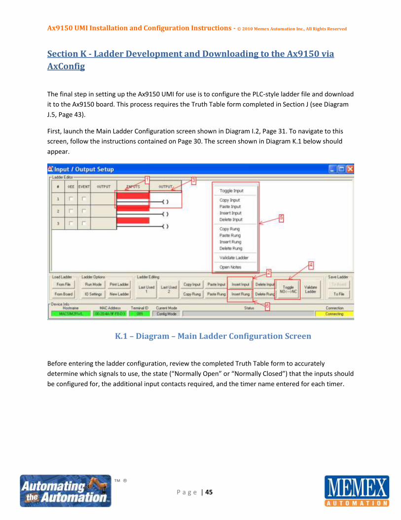
First, launch the Main Ladder Configuration screen shown in Diagram I.2, Page 31. To navigate to this
screen, follow the instructions contained on Page 30. The screen shown in Diagram K.1 below should
appear.
K.1 – Diagram – Main Ladder Configuration Screen
Before entering the ladder configuration, review the completed Truth Table form to accurately
determine which signals to use, the state (“Normally Open” or “Normally Closed”) that the inputs should
be configured for, the additional input contacts required, and the timer name entered for each timer.
Ax9150 UMI Installation and Configuration Instructions - © 2010 Memex Automation Inc., All Rights Reserved
™ ®
P a g e | 46
Additional useful function buttons are available to assist in the development and manipulation of the
ladder configuration file. They are:
For Input editing – “Copy Input”, “Past Input”, “Delete Input”, “Last Used 1”, “Last Used 2”
For Rung editing - “Copy Rung”, “Paste Rung”, “Insert Rung”, “Delete Rung”
General - “Print Ladder”, “New Ladder”
Load Ladder Configuration File – “From Board”, “From File” (used to edit an existing ladder
configuration file)
Right Click menu also has most of the above handy function buttons (Diagram K.1, Page 45, Item
4)
K.2 - Review of Differences between Contact Types
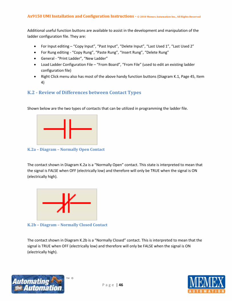
Shown below are the two types of contacts that can be utilized in programming the ladder file.
K.2a – Diagram – Normally Open Contact
The contact shown in Diagram K.2a is a “Normally Open” contact. This state is interpreted to mean that
the signal is FALSE when OFF (electrically low) and therefore will only be TRUE when the signal is ON
(electrically high).
K.2b – Diagram – Normally Closed Contact
The contact shown in Diagram K.2b is a “Normally Closed” contact. This is interpreted to mean that the
signal is TRUE when OFF (electrically low) and therefore will only be FALSE when the signal is ON
(electrically high).

Ax9150 UMI Installation and Configuration Instructions - © 2010 Memex Automation Inc., All Rights Reserved
™ ®
P a g e | 47
K.3 - How to Write a Ladder Rung
In our example, we are going to enter a rung to track ESTOP. We can conclude from our Truth Table
form that, when the CNC machine was in an ESTOP condition, the ESTOP contact was low (OFF), and the
INCYCLE input was also low (OFF) as the machine was not INCYCLE during an ESTOP condition. This
means that we are using the “Normally Closed” contact state of both inputs. We also wish to ignore the
ESTOP state when the CNC machine is in SETUPMODE, MAINTENANCE SCHEDULED, or MAINTENANCE
UNSCHEDULED modes. We need to therefore add “Normally Closed” contacts for these modes as well
so that the ESTOP input is ignored when the CNC machine is put into any one of these three modes.
K.4 - Example Recap
As shown in the Truth Table form example in Diagram J.5 on Page 43, the rung of logic for the ESTOP
condition has a “Normally Closed” ESTOP, a “Normally Closed” INCYCLE, and a “Normally Closed”
contact for each of the SETUPMODE, MAINTENANCE SCHEDULED, or MAINTENANCE UNSCHEDULED
modes. These contacts should be entered into AxConfig by first placing the cursor at the Inputs column
of line 1 (Diagram K.1, Page 45, item 1) and pressing the “Insert Input” button (item 2). Key in the input
number by pressing the “Backspace” key three times and entering the I## (where ## is the number
from 00 to 31), or enter the text defined as the input in the I/O Translation tab (see Diagram J.2, Page
37). Next, highlight this input and press the “Toggle NO < -- > NC” button (Diagram K.1, Page 45, Item 4)
to change the state of the contact to “Normally Closed”. Had this been a “Normally Open” contact, this
step would have been omitted. As an alternative, all of these button items can be found in menu format
by simply right clicking on any square in the ladder input section (see Diagram K.1, page 45, item 5).
Next, use the right arrow key on the keyboard to move one space over to the Output column (Diagram
K.1, item 3) and repeat the insert and naming process for the remaining inputs on this rung of logic
according to the Truth Table form. Once all of the inputs have been entered, enter the timer name by
placing the cursor on the Output column (Diagram K.1, Page 45 item 3) and keying in either the timer
number (T##, where ## is the timer number from 01 to 20), or the name as it has been defined in the
PACE translation tab (see Diagram J.1, Page 37).
Place the cursor on the last timer (in this example ESTOP) and press the “Insert Rung” button (Diagram
K.1, Page 45, Item 6) to create a new rung. Continue entering the rest of the required data for all of the
input timers.
K.5 - Key Points to Remember when Writing the Ladder Configuration File The information entered into AxConfig during this configuration step has either been previously entered
in a tab in AxConfig (for the hard-wired or soft inputs; refer to the I/O Translation tab – Diagram I.4,
Page 32; or for the timer outputs T01 – T20; refer to the PACE Translation tab - Diagram I.5, Page 33. The
state information (Normally Open or Normally Closed) is taken directly from the Truth Table form
Ax9150 UMI Installation and Configuration Instructions - © 2010 Memex Automation Inc., All Rights Reserved
™ ®
P a g e | 48
(Diagram J.5, Page 43). For an understanding of the differences between “Normally Open” and
“Normally Closed”, refer to Diagrams K.2a and K.2b on Page 46.
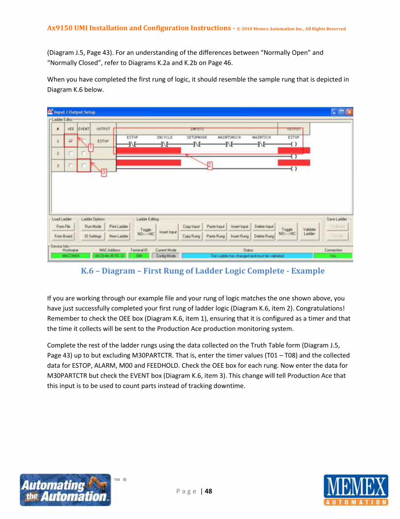
When you have completed the first rung of logic, it should resemble the sample rung that is depicted in
Diagram K.6 below.
K.6 – Diagram – First Rung of Ladder Logic Complete - Example
If you are working through our example file and your rung of logic matches the one shown above, you
have just successfully completed your first rung of ladder logic (Diagram K.6, item 2). Congratulations!
Remember to check the OEE box (Diagram K.6, item 1), ensuring that it is configured as a timer and that
the time it collects will be sent to the Production Ace production monitoring system.
Complete the rest of the ladder rungs using the data collected on the Truth Table form (Diagram J.5,
Page 43) up to but excluding M30PARTCTR. That is, enter the timer values (T01 – T08) and the collected
data for ESTOP, ALARM, M00 and FEEDHOLD. Check the OEE box for each rung. Now enter the data for
M30PARTCTR but check the EVENT box (Diagram K.6, item 3). This change will tell Production Ace that
this input is to be used to count parts instead of tracking downtime.

Ax9150 UMI Installation and Configuration Instructions - © 2010 Memex Automation Inc., All Rights Reserved
™ ®
P a g e | 49
When you have completed the example ladder data for the hard-wired inputs only, your configuration
file should resemble that shown in Diagram K.7 below.
K.7 – Diagram – All Hard-wired Ladder Rungs Complete - Example
In the example above, we have entered a rung for each timer that has been assigned (T01 – T08) and
identified in our Truth Table form (Diagram J.5, Page 43; PACE Translation tab, Diagram J.1, Page 37).
The rung logic is depicted in section 1 above. The timer name that corresponds to the data input into
PACE Translation tab, Diagram J.1, Page 37 is shown in Section 1A above.
The OEE box (Diagram K.7, item 2) is checked for all inputs except M30PARTCTR, which is to count parts
made automatically and so requires the checking of the EVENT box (Diagram K.7, item 3).
We now need to add the remainder of the rungs for the soft inputs as well as for IDLE mode. Place the
cursor on the last timer (in this example M30PARTCTR; Diagram K.7, item 4) and press the “Insert Rung”
button (item 5). A new rung is created in which additional data can be entered. This action can be
repeated as needed to provide new rungs for data for additional soft input timers.
Ax9150 UMI Installation and Configuration Instructions - © 2010 Memex Automation Inc., All Rights Reserved
™ ®
P a g e | 50
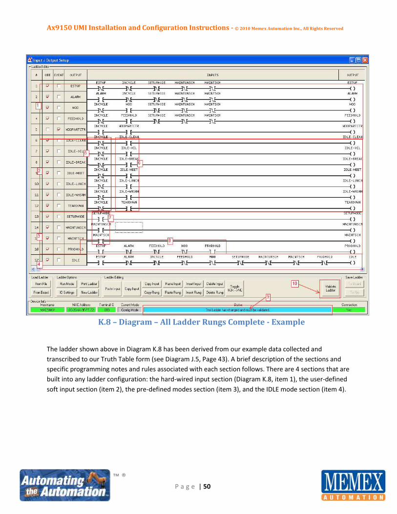
K.8 – Diagram – All Ladder Rungs Complete - Example
The ladder shown above in Diagram K.8 has been derived from our example data collected and
transcribed to our Truth Table form (see Diagram J.5, Page 43). A brief description of the sections and
specific programming notes and rules associated with each section follows. There are 4 sections that are
built into any ladder configuration: the hard-wired input section (Diagram K.8, item 1), the user-defined
soft input section (item 2), the pre-defined modes section (item 3), and the IDLE mode section (item 4).
Ax9150 UMI Installation and Configuration Instructions - © 2010 Memex Automation Inc., All Rights Reserved
™ ®
P a g e | 51
1. The hard-wired input section uses the information that was collected by the development of the
Truth Table for timers T01 – T08. Care must be taken to ensure that the correct state of each
hard-wired input is used (Normally Open or Normally Closed) so that the rung will function as
intended and the system will accurately track downtime from the CNC machine when these
inputs are either ON (Normally Open type; see Diagram K.2a, Page 46), or OFF (Normally Closed
type; see Diagram K.2b, Page 46).
2. The user-defined soft input section (T09 to T14) as defined in the PACE translation tab uses the
soft inputs as defined in the PACE Translation tab (see Diagram J.1, Page 37). These modes are
driven from the Mx2000 HOI terminal when the CNC machine is dwelling in an IDLE state and
are presented to the operator as downtime reason codes. The operator can then make a choice
to further isolate the root cause of the machine’s downtime.
SUGGESTED RULES: There should ALWAYS be a Normally Closed contact (item 5 in Diagram K.8,
Page 50) and a Normally Open input contact (item 6 in Diagram K.8, Page 50) labelled EXACTLY
as they were defined in the I/O Translation tab (I08 to I27). The timers from T09 to T15 should
be labeled EXACTLY as they were defined in the PACE Translation tab (see Diagram J.1, Page 37).
3. The pre-defined modes section (item 3 in Diagram K.8, Page 50) utilizes T16 – T19 as pre-defined
in the PACE Translation tab (see Diagram I.5, Page 33) using the pre-defined soft inputs (I28 –
I31) in the I/O Translation tab (see Diagram I.4, Page 32). This section is configured by adding a
Normally Open contact of SETUP (I28) with its corresponding timer named SETUP (T16). Repeat
this process for MAINTUNSCH (I29/T17) and MAINTSCH (I30/T18). For reference, see item 7 in
Diagram K.8, Page 50. Production Hold (PRODHOLD) requires a contact of the OFF state for each
of the hard-wired inputs, plus a Normally Open contact of the pre-defined input PRODHOLD
(I31) to immediately precede the pre-defined timer PRODHOLD (T19). For reference, see item 8,
in Diagram K.8, Page 50.
4. The IDLE mode rung is the “catch-all” rung. If there is no downtime reason code currently active,
the downtime will be caught in IDLE mode (predefined as T20 in the PACE Translation tab; see
Diagram I.5, Page 33). This rung is also utilized to drive the user-defined downtime reason codes
(see point 2 above) to the Mx2000 HOI terminal. These reason codes are presented to the
operator for selection each time the CNC machine dwells in an IDLE state. As discussed
previously, and as shown in Diagram I.5 on Page 33, (Items 4,5,6) the timers are prioritized from
T20 (lowest) to T01 (highest), so that any active rung numerically below T20 will take
precedence. Should a rung be true that is above IDLE, the machine downtime will accumulate on
this rung.
The IDLE rung contains a contact of the OFF state for each of the hard-wired inputs (point 1
above), a Normally Closed contact for each one of the pre-defined modes (point 3 above), and a
Normally Closed contact for INCYCLE (which refers to the fact that the machine is not INCYCLE).

Ax9150 UMI Installation and Configuration Instructions - © 2010 Memex Automation Inc., All Rights Reserved
™ ®
P a g e | 52
Close adherence to the above process will allow the installer to configure a simple ladder
configuration file to be downloaded to the Ax9150 UMI. There are additional complexities that
can be added, such as a specific input to drive an IDLE state, but the above basic methodology
configures the board to accept input stimuli and sets timer outputs to accurately and effectively
track the machine’s downtime. The file must now be validated and downloaded to the Ax9150
UMI (see items 9 and 10, Diagram K.8, Page 50), a process described in Diagram K.10 on Page
53.
K.9 - Special Note on Ladder Programming
It should be noted that only the input that drives the timer need be referenced in the ladder rung. It is
not necessary to use all of the other contacts in the rung except for the contact that depicts NOT
INCYCLE, which is an ABSOLUTE MUST. The timers work on a cascading system (mutually exclusive from
lowest to highest) from T20 (least significant) to T1 (most significant). If two timers are on at the same
time, the one with the higher priority (lower number) collects the time. For example, if Alarm Active
signals, then an ESTOP is pressed. We have not explicitly excluded ALARM with an ESTOP contact in its
rung because this is addressed automatically in the background. This provision greatly simplifies the
writing of the ladder program.
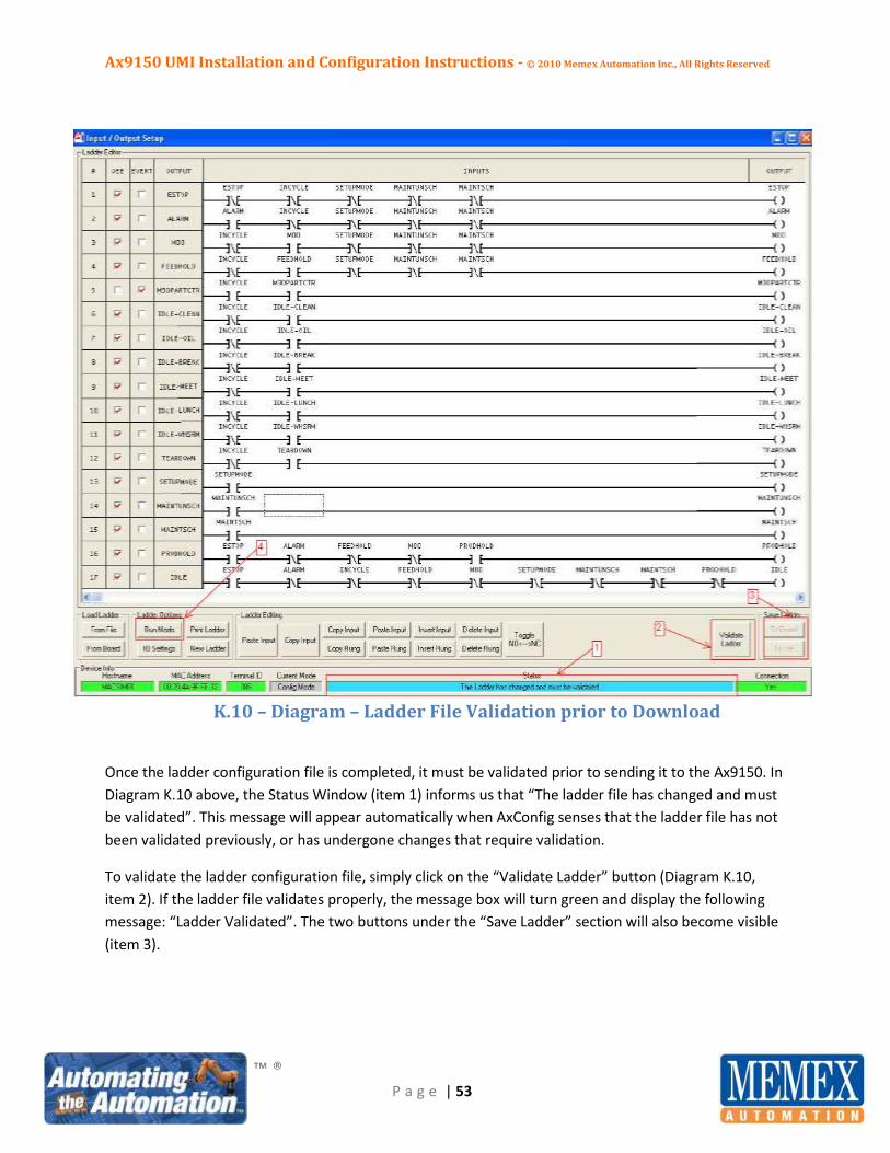
Ax9150 UMI Installation and Configuration Instructions - © 2010 Memex Automation Inc., All Rights Reserved
™ ®
P a g e | 53
K.10 – Diagram – Ladder File Validation prior to Download
Once the ladder configuration file is completed, it must be validated prior to sending it to the Ax9150. In
Diagram K.10 above, the Status Window (item 1) informs us that “The ladder file has changed and must
be validated”. This message will appear automatically when AxConfig senses that the ladder file has not
been validated previously, or has undergone changes that require validation.
To validate the ladder configuration file, simply click on the “Validate Ladder” button (Diagram K.10,
item 2). If the ladder file validates properly, the message box will turn green and display the following
message: “Ladder Validated”. The two buttons under the “Save Ladder” section will also become visible
(item 3).
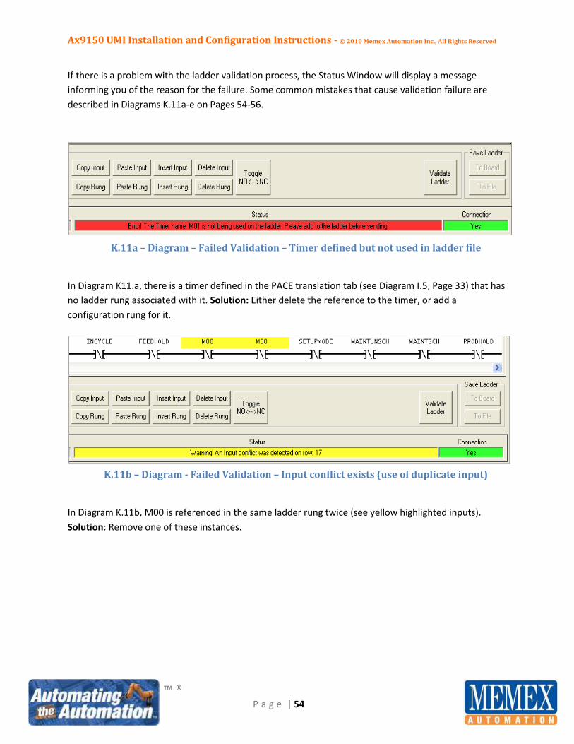
Ax9150 UMI Installation and Configuration Instructions - © 2010 Memex Automation Inc., All Rights Reserved
™ ®
P a g e | 54
If there is a problem with the ladder validation process, the Status Window will display a message
informing you of the reason for the failure. Some common mistakes that cause validation failure are
described in Diagrams K.11a-e on Pages 54-56.
K.11a – Diagram – Failed Validation – Timer defined but not used in ladder file
In Diagram K11.a, there is a timer defined in the PACE translation tab (see Diagram I.5, Page 33) that has
no ladder rung associated with it. Solution: Either delete the reference to the timer, or add a
configuration rung for it.
K.11b – Diagram - Failed Validation – Input conflict exists (use of duplicate input)
In Diagram K.11b, M00 is referenced in the same ladder rung twice (see yellow highlighted inputs).
Solution: Remove one of these instances.

Ax9150 UMI Installation and Configuration Instructions - © 2010 Memex Automation Inc., All Rights Reserved
™ ®
P a g e | 55
K.11c – Diagram – Failed Validation – Invalid input detected
In Diagram K11.c, I33 is not a valid input number or name. Solution: Correct the input number or name.
K.11d – Diagram – Failed Validation – Duplicate timer used
In Diagram K.11d, the MAINTSCH timer has been used on two different rungs. Solution: Delete one of
the rungs.
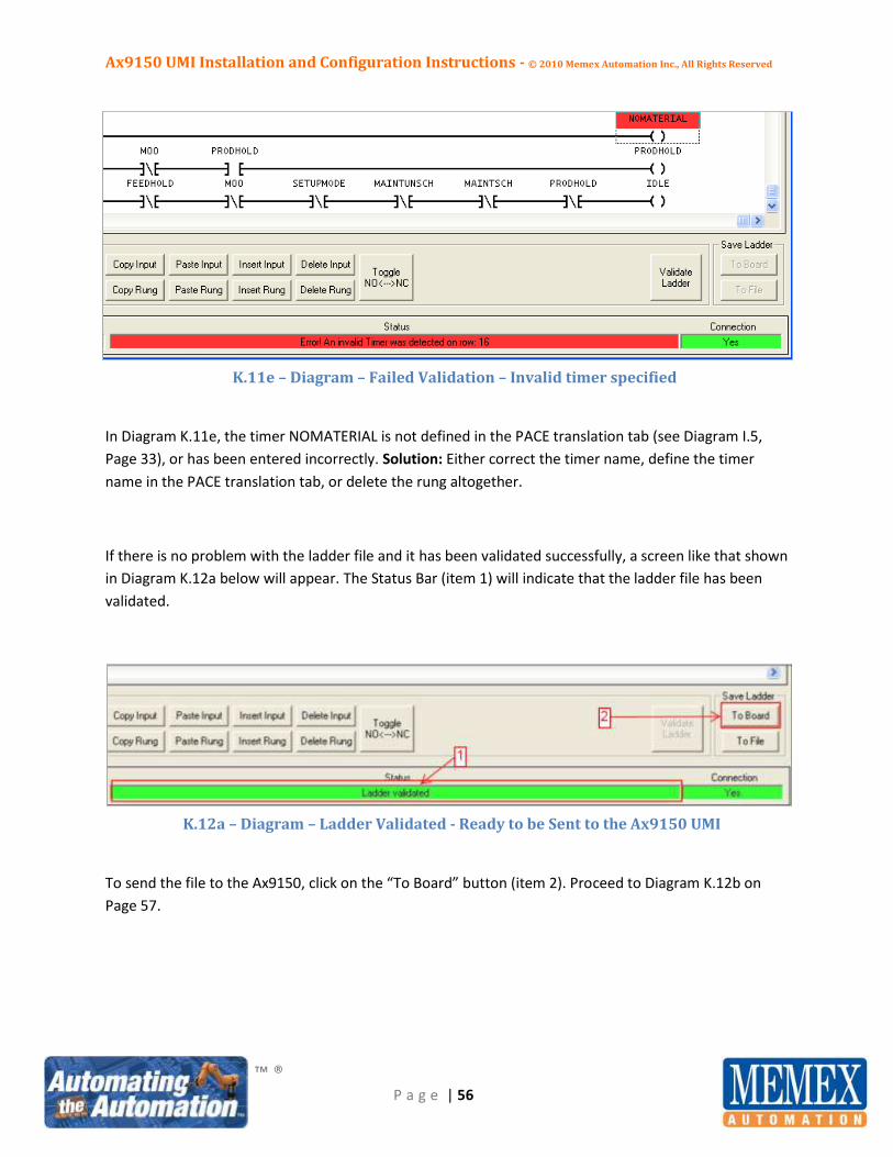
Ax9150 UMI Installation and Configuration Instructions - © 2010 Memex Automation Inc., All Rights Reserved
™ ®
P a g e | 56
K.11e – Diagram – Failed Validation – Invalid timer specified
In Diagram K.11e, the timer NOMATERIAL is not defined in the PACE translation tab (see Diagram I.5,
Page 33), or has been entered incorrectly. Solution: Either correct the timer name, define the timer
name in the PACE translation tab, or delete the rung altogether.
If there is no problem with the ladder file and it has been validated successfully, a screen like that shown
in Diagram K.12a below will appear. The Status Bar (item 1) will indicate that the ladder file has been
validated.
K.12a – Diagram – Ladder Validated - Ready to be Sent to the Ax9150 UMI
To send the file to the Ax9150, click on the “To Board” button (item 2). Proceed to Diagram K.12b on
Page 57.

Ax9150 UMI Installation and Configuration Instructions - © 2010 Memex Automation Inc., All Rights Reserved
™ ®
P a g e | 57
K.12b – Diagram – Ladder Configuration File being sent to the Ax9150 UMI
In Diagram K.12b, the Ax9150 board is receiving the configuration file from AxConfig (item 1). Proceed
to Diagram K.12c shown below.
K.12c – Diagram – Ladder Configuration File - Sending completed
In Diagram K.12c, the Ax9150 has successfully received its ladder configuration file and the Status bar
says “I/O configuration completed” (item 1). The ladder configuration process is now complete.

Ax9150 UMI Installation and Configuration Instructions - © 2010 Memex Automation Inc., All Rights Reserved
™ ®
P a g e | 58
Section L - Monitoring the Status of the Configuration Resident in the
Ax9150 UMI
Now that the validated configuration file has been downloaded to the Ax9150, the CNC machine’s
operation can be monitored by clicking on the “Run Mode” button as shown in item 4, Diagram K.10,
Page 53. The Input/Output Set-up screen will resemble that shown in Diagram L.1 on Page 59.
The actual machine signals will change from white to green based on the actual input status. When a set
of conditions is all true in a rung, that entire rung of logic will turn green, which in turn causes the
configured timer to begin collecting downtime (Diagram L.1, Page 59, item 3). If any of the contacts
located in the rung changes state, the timer changes from green to white, that rung will become false
and the timer will cease collecting downtime (Diagram L.1, Page 59, item 2). When in Run Mode, all
buttons across the bottom are disabled, with the exception of the “Config Mode” button, which will
return you to the screen shown in Diagram K.10, Page 53. Pressing the “Run Mode” button is useful for
troubleshooting and debugging machine signals in real-time, using the actual machine input stimuli.

Ax9150 UMI Installation and Configuration Instructions - © 2010 Memex Automation Inc., All Rights Reserved
™ ®
P a g e | 59
L.1 – Diagram – Ladder Monitoring in Run Mode

Ax9150 UMI Installation and Configuration Instructions - © 2010 Memex Automation Inc., All Rights Reserved
™ ®
P a g e | 60
Section M - Mx2000 HOI Terminal – Emulation
AxConfig has a mode in which the Mx2000 HOI terminal can be monitored remotely. This capacity is
helpful for troubleshooting operator concerns, or for investigating/interrogating the machine from a
distant location.
To access this mode, simply click on the Tools menu in AxConfig and select the “Mx2000 Emulator”
menu item. A screen like that shown in Diagram M.1 below will appear showing the actual content of
the Mx2000 HOI terminal. The contents on this screen are EXACTLY the same as those displayed by the
Mx2000 HOI to the operator on the shop floor. All commands and command buttons are available, just
as if you were standing in front of the CNC machine looking at the actual Mx2000 HOI.
M.1 – Diagram – Mx2000 Terminal Emulation via AxConfig

Ax9150 UMI Installation and Configuration Instructions - © 2010 Memex Automation Inc., All Rights Reserved
™ ®
P a g e | 61
Section N - Ax9150 UMI Firmware Upgrade via AxConfig
One of the most powerful features of the Ax9150 UMI is its ability to support remote upgrading of its
firmware. The firmware resident in the board is the operating system by which the board functions. The
ability to upgrade the board remotely means that once it is installed, there is no need to remove it to
upgrade its core functions. Many firmware options are available for the Ax9150, and all can be
downloaded remotely. It is recommended that you consult Memex before attempting a firmware
upgrade.
To access the Firmware Upgrade screen, click on Tools, then Firmware Upgrade. The screen shown
below in Diagram N.1. will appear. Choose the file path containing the new firmware file and press the
download button. If the firmware does not download correctly, press the reset button and then try
again. To ask the board which version of firmware is installed, press the Query button.
N.1 - Diagram – Firmware Upgrade via AxConfig
End of Ax9150 UMI Installation / Configuration Manual
Memex constantly strives to engineer products that exceed our customers expectations. For specific
hardware interface installation information, please consult the installation manual appropriate for the
specific device that you are attempting to install.

Ax9150 UMI Installation and Configuration Instructions - © 2010 Memex Automation Inc., All Rights Reserved
™ ®
P a g e | 62
Appendix A – Blank Truth Table Form
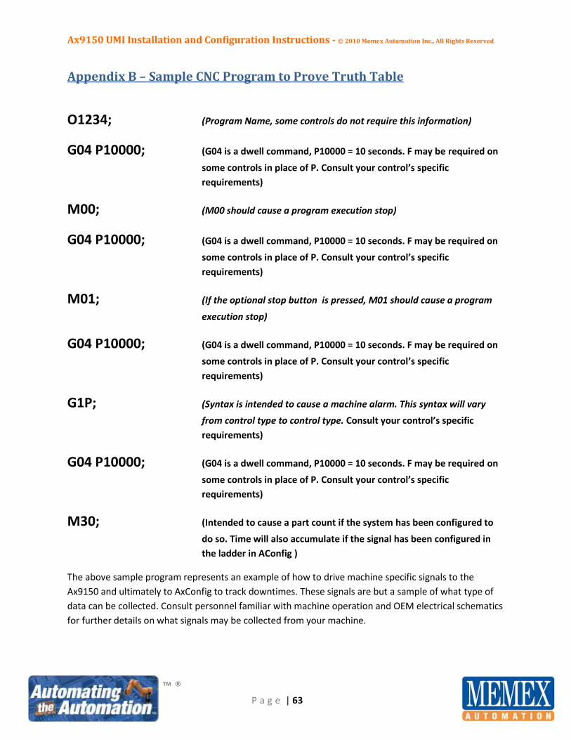
Ax9150 UMI Installation and Configuration Instructions - © 2010 Memex Automation Inc., All Rights Reserved
™ ®
P a g e | 63
Appendix B – Sample CNC Program to Prove Truth Table
O1234; (Program Name, some controls do not require this information)
G04 P10000; (G04 is a dwell command, P10000 = 10 seconds. F may be required on
some controls in place of P. Consult your control’s specific
requirements)
M00; (M00 should cause a program execution stop)
G04 P10000; (G04 is a dwell command, P10000 = 10 seconds. F may be required on
some controls in place of P. Consult your control’s specific
requirements)
M01; (If the optional stop button is pressed, M01 should cause a program
execution stop)
G04 P10000; (G04 is a dwell command, P10000 = 10 seconds. F may be required on
some controls in place of P. Consult your control’s specific
requirements)
G1P; (Syntax is intended to cause a machine alarm. This syntax will vary
from control type to control type. Consult your control’s specific
requirements)
G04 P10000; (G04 is a dwell command, P10000 = 10 seconds. F may be required on
some controls in place of P. Consult your control’s specific
requirements)
M30; (Intended to cause a part count if the system has been configured to
do so. Time will also accumulate if the signal has been configured in
the ladder in AConfig )
The above sample program represents an example of how to drive machine specific signals to the
Ax9150 and ultimately to AxConfig to track downtimes. These signals are but a sample of what type of
data can be collected. Consult personnel familiar with machine operation and OEM electrical schematics
for further details on what signals may be collected from your machine.