axi4-stream infrastructure ip suite - xilinx axi4-stream infrastructure ip suite is a powerful...
TRANSCRIPT

AXI4-Stream Infrastructure IP Suite
Product Guide for Vivado Design Suite
PG085 March 20, 2013
AXI4‐Stream Infrastructure IP Suite www.xilinx.com 2PG085 March 20, 2013
Table of Contents
IP Facts
Chapter 1: Overview
Overview of Features. . . . . . . . . . . . . . . . . . . . . . . . . . . . . . . . . . . . . . . . . . . . . . . . . . . . . . . . . . . . . . . 6
System Requirements . . . . . . . . . . . . . . . . . . . . . . . . . . . . . . . . . . . . . . . . . . . . . . . . . . . . . . . . . . . . . . 8
Licensing and Ordering Information . . . . . . . . . . . . . . . . . . . . . . . . . . . . . . . . . . . . . . . . . . . . . . . . . . . 8
Chapter 2: Product Specification
AXI4‐Stream Infrastructure IP Suite Modules . . . . . . . . . . . . . . . . . . . . . . . . . . . . . . . . . . . . . . . . . . . 9
Standards . . . . . . . . . . . . . . . . . . . . . . . . . . . . . . . . . . . . . . . . . . . . . . . . . . . . . . . . . . . . . . . . . . . . . . . 15
Performance. . . . . . . . . . . . . . . . . . . . . . . . . . . . . . . . . . . . . . . . . . . . . . . . . . . . . . . . . . . . . . . . . . . . . 15
Resource Utilization. . . . . . . . . . . . . . . . . . . . . . . . . . . . . . . . . . . . . . . . . . . . . . . . . . . . . . . . . . . . . . . 18
Port Descriptions . . . . . . . . . . . . . . . . . . . . . . . . . . . . . . . . . . . . . . . . . . . . . . . . . . . . . . . . . . . . . . . . . 20
Chapter 3: Designing with the Core
General Design Guidelines . . . . . . . . . . . . . . . . . . . . . . . . . . . . . . . . . . . . . . . . . . . . . . . . . . . . . . . . . 24
Clocking. . . . . . . . . . . . . . . . . . . . . . . . . . . . . . . . . . . . . . . . . . . . . . . . . . . . . . . . . . . . . . . . . . . . . . . . . 25
Resets . . . . . . . . . . . . . . . . . . . . . . . . . . . . . . . . . . . . . . . . . . . . . . . . . . . . . . . . . . . . . . . . . . . . . . . . . . 26
Chapter 4: Customizing and Generating the Core
Creating a Project. . . . . . . . . . . . . . . . . . . . . . . . . . . . . . . . . . . . . . . . . . . . . . . . . . . . . . . . . . . . . . . . . 27
Customizing and Generating the Core . . . . . . . . . . . . . . . . . . . . . . . . . . . . . . . . . . . . . . . . . . . . . . . . 28
Output Generation. . . . . . . . . . . . . . . . . . . . . . . . . . . . . . . . . . . . . . . . . . . . . . . . . . . . . . . . . . . . . . . . 57
Chapter 5: Constraining the Core
Appendix A: Debugging
Finding Help on Xilinx.com . . . . . . . . . . . . . . . . . . . . . . . . . . . . . . . . . . . . . . . . . . . . . . . . . . . . . . . . . 60
Debug Tools . . . . . . . . . . . . . . . . . . . . . . . . . . . . . . . . . . . . . . . . . . . . . . . . . . . . . . . . . . . . . . . . . . . . . 62
Hardware Debug . . . . . . . . . . . . . . . . . . . . . . . . . . . . . . . . . . . . . . . . . . . . . . . . . . . . . . . . . . . . . . . . . 62
Interface Debug . . . . . . . . . . . . . . . . . . . . . . . . . . . . . . . . . . . . . . . . . . . . . . . . . . . . . . . . . . . . . . . . . . 63
AXI4‐Stream Infrastructure IP Suite www.xilinx.com 3PG085 March 20, 2013
Appendix B: Additional Resources
Xilinx Resources . . . . . . . . . . . . . . . . . . . . . . . . . . . . . . . . . . . . . . . . . . . . . . . . . . . . . . . . . . . . . . . . . . 64
References . . . . . . . . . . . . . . . . . . . . . . . . . . . . . . . . . . . . . . . . . . . . . . . . . . . . . . . . . . . . . . . . . . . . . . 64
Revision History . . . . . . . . . . . . . . . . . . . . . . . . . . . . . . . . . . . . . . . . . . . . . . . . . . . . . . . . . . . . . . . . . . 64
Notice of Disclaimer. . . . . . . . . . . . . . . . . . . . . . . . . . . . . . . . . . . . . . . . . . . . . . . . . . . . . . . . . . . . . . . 65
AXI4‐Stream Infrastructure IP Suite www.xilinx.com 4PG085 March 20, 2013 Product Specification
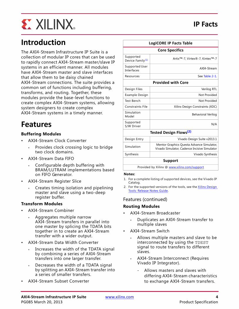
IntroductionThe AXI4-Stream Infrastructure IP Suite is a collection of modular IP cores that can be used to rapidly connect AXI4-Stream master/slave IP systems in an eff icient manner. All modules have AXI4-Stream master and slave interfaces that allow them to be daisy chained AXI4-Stream connections. The suite provides a common set of functions including buffering, transforms, and routing. Together, these modules provide the base-level functions to create complex AXI4-Stream systems, allowing system designers to create complex AXI4-Stream systems in a timely manner.
FeaturesBuffering Modules• AXI4-Stream Clock Converter
° Provides clock crossing logic to bridge two clock domains.
• AXI4-Stream Data FIFO
° Configurable depth buffering with BRAM/LUTRAM implementations based on FIFO Generator.
• AXI4-Stream Register Slice
° Creates timing isolation and pipelining master and slave using a two-deep register buffer.
Transform Modules• AXI4-Stream Combiner
° Aggregates multiple narrow AXI4-Stream transfers in parallel into one master by splicing the TDATA bits together in to create an AXI4-Stream transfer with a wider output.
• AXI4-Stream Data Width Converter
° Increases the width of the TDATA signal by combining a series of AXI4-Stream transfers into one larger transfer.
° Decreases the width of a TDATA signal by splitting an AXI4-Stream transfer into a series of smaller transfers.
• AXI4-Stream Subset Converter
Features (continued)Routing Modules• AXI4-Stream Broadcaster
° Duplicates an AXI4-Stream transfer to multiple slaves
• AXI4-Stream Switch
° Allows multiple masters and slave to be interconnected by using the TDEST signal to route transfers to different slaves.
° AXI4-Stream Interconnect (Requires Vivado IP Integrator).
- Allows masters and slaves with differing AXI4-Stream characteristics to exchange AXI4-Stream transfers.
IP Facts
LogiCORE IP Facts Table
Core Specifics
Supported Device Family(1) Artix™-7, Virtex®-7, Kintex™-7
Supported User Interfaces AXI4-Stream
Resources See Table 2-1.
Provided with Core
Design Files Verilog RTL
Example Design Not Provided
Test Bench Not Provided
Constraints File Xilinx Design Constraints (XDC)
Simulation Model Behavioral Verilog
Supported S/W Driver N/A
Tested Design Flows(2)
Design Entry Vivado Design Suite v2013.1
Simulation Mentor Graphics Questa Advance Simulator,Vivado Simulator, Cadence Incisive Simulator
Synthesis Vivado Synthesis
Support
Provided by Xilinx @ www.xilinx.com/support
Notes: 1. For a complete listing of supported devices, see the Vivado IP
Catalog.2. For the supported versions of the tools, see the Xilinx Design
Tools: Release Notes Guide.
AXI4‐Stream Infrastructure IP Suite www.xilinx.com 5PG085 March 20, 2013
Chapter 1
OverviewThe ARM® AMBA® 4 Specif ication builds on the AMBA 3 specif ications by adding new interface protocols to provide greater interface flexibility in designs with open standards. Among the new interface protocols is the AXI4-Stream interface which is designed to support low resource, high bandwidth unidirectional data transfers. It is well-suited for FPGA implementation because the transfer protocol allows for high frequency versus clock latency trade-offs to help meet design goals.
The AXI4-Stream protocol is derived from the single AXI3 write channel. It has no corresponding address or response channel and is capable of non-deterministic burst transactions (undefined length). The protocol interface signal set adds optional signals to support data routing, end of transaction indicators, and null-beat modif iers to facilitate management and movement of data across a system. These characteristics are suitable for transferring large amounts of data eff iciently while keeping gate count low.
The protocol interface consists of a master interface and a slave interface. The two interfaces are symmetric and point-to-point, such that master interface output signals can connect directly to the slave interface input signals. Utilizing this concept, it is possible to design AXI4-Stream modules that have a slave interface input channel and a master interface output channel. Because the master and slave interfaces are symmetric, any number of these modules can be daisy-chained together by connecting the master interface output channel of one module to the slave interface input channel of another module and so on. The function of the modules can be a multitude of different options such as buffering, data transforming or routing.
The AXI4-Stream Infrastructure IP Suite is a powerful collection of modules that provides a rich set of functions for connecting together AXI4-Stream masters and slaves. The IP core is capable of performing data switching/routing, data width conversion, pipelining, clock conversion and data buffering. Parameters and IP configuration Graphical User Interfaces (GUIs) are used to configure the core to suit each of the system designer's requirements.
AXI4‐Stream Infrastructure IP Suite www.xilinx.com 6PG085 March 20, 2013
Chapter 1: Overview
Overview of FeaturesThe AXI4-Stream Infrastructure IP Suite consists of eight modular IP cores supporting the full AXI4-Stream specif ication. Common features include:
• AXI4-Stream compliant
° Supports all AXI4-Stream defined signals: TVALID, TREADY, TDATA , TSTRB, TKEEP, TLAST, TID, TDEST, and TUSER.
° TDATA, TSTRB, TKEEP, TLAST, TID, TDEST, and TUSER are optional.
° Programmable TDATA, TID, TDEST, and TUSER widths (TSTRB and TKEEP width is TDATA width/8).
° ACLK/ARESETn ports.
° Per port ACLKEN inputs (optional).
AXI4-Stream Broadcaster• Replicates a master stream into multiple output slave streams.
• Provides TDATA/TUSER remap functionality.
• Supports 2-16 slaves.
AXI4-Stream Clock Converter• Supports low latency and area synchronous 1:N and N:1 clock conversion.
• Supports asynchronous clock conversion (utilizing FIFO Generator.
• Supports configurable ACLKEN conversion.
AXI4-Stream Combiner• Combines multiple "narrow" streams into one wide output stream.
• Supports 2-16 masters.
• Supports error detection for unmatched TLAST, TID, or TDEST signals slave interfaces.
AXI4-Stream Data FIFO• Supports 16 and 32 depth FIFOs using LUTRAM primitives.
• Supports 64, 128, 256, 512, 1024, 2048, 4096 depth using Block RAM primitives.
• Uses FIFO Generator.
• Supports asynchronous clocking and ACLKEN conversion.
• Supports Packet Mode (Store and Forward based on TLAST.)
AXI4‐Stream Infrastructure IP Suite www.xilinx.com 7PG085 March 20, 2013
Chapter 1: Overview
AXI4-Stream Data Width Converter• Supports 1:N TDATA width size increase in a single stage.
• Supports N:1 TDATA width size decrease in a single stage.
• Supports arbitrary M:N TDATA width conversion in multiple stages.
AXI4-Stream Register Slice• Allows pipelining of AXI4-Streams.
• Provides timing isolation.
• Implemented using a depth of two "skid buffer."
AXI4-Stream Subset Converter• Provides TDATA/TUSER remap functionality.
• Allows streams with different signal sets to be connected.
• Can generate a programmable TLAST.
• Can tie-off unused signals from masters.
• Can add signals based on default value rules.
AXI4-Stream Switch• Supports 1-16 slaves.
• Supports 1-16 masters.
• Has slave side arbitrated crossbar switch.
• Supports multiple arbitration tuning points:
° Ability to arbitrate based on TLAST.
° Ability to arbitrate based on number of transfers.
° Ability to arbitrate based on a timeout (counts number of consecutive LOW TVALID cycles.)
• Supports Round-Robin and Fixed Priority arbitration choices.
• Supports sparse connectivity.
• Supports static routing based on TDEST base/high pairs.
AXI4-Stream InterconnectNote: AXI4-Stream Interconnect requires Vivado IP Integrator.
• Supports 1-16 slaves
• Supports 1-16 slaves
AXI4‐Stream Infrastructure IP Suite www.xilinx.com 8PG085 March 20, 2013
Chapter 1: Overview
• Combines AXI4-Stream Switch with buffering modules, AXI4-Stream Data Width Converter and AXI4-Stream Subset Converter to allow masters and slaves with varying AXI4-Stream characteristics to exchange AXI4-Stream transfers
System RequirementsFor a list of System Requirements, see the Xilinx Design Tools: Release Notes Guide.
Licensing and Ordering InformationThis Xilinx LogiCORE™ IP module is provided at no additional cost with the Xilinx Vivado™ Design Suite and ISE® Design Suite tools under the terms of the Xilinx End User License. Information about this and other Xilinx LogiCORE IP modules is available at the Xilinx Intellectual Property page. For information about pricing and availability of other Xilinx LogiCORE IP modules and tools, contact your local Xilinx sales representative.
AXI4‐Stream Infrastructure IP Suite www.xilinx.com 9PG085 March 20, 2013
Chapter 2
Product Specification
AXI4‐Stream Infrastructure IP Suite Modules
AXI4‐Stream Broadcaster
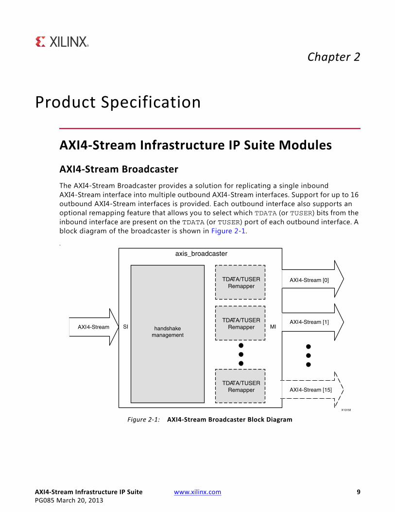
The AXI4-Stream Broadcaster provides a solution for replicating a single inbound AXI4-Stream interface into multiple outbound AXI4-Stream interfaces. Support for up to 16 outbound AXI4-Stream interfaces is provided. Each outbound interface also supports an optional remapping feature that allows you to select which TDATA (or TUSER) bits from the inbound interface are present on the TDATA (or TUSER) port of each outbound interface. A block diagram of the broadcaster is shown in Figure 2-1.
MX-Ref Target - Figure 2-1
Figure 2‐1: AXI4‐Stream Broadcaster Block Diagram
AXI4‐Stream Infrastructure IP Suite www.xilinx.com 10PG085 March 20, 2013
Chapter 2: Product Specification
AXI4‐Stream Clock Converter
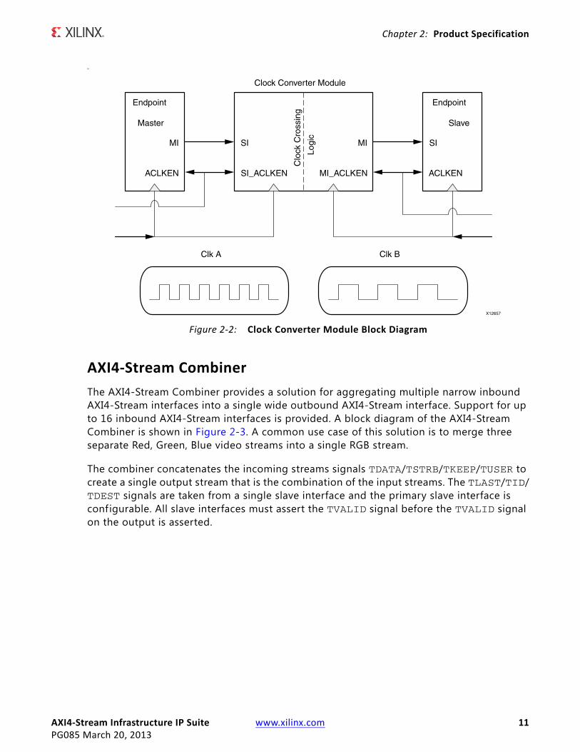
Clock converters are necessary in the AXI4-Stream protocol for converting masters operating at different clock rates to slaves. Typically, the AXI4-Stream Infrastructure IP should be clocked at the same rate as the fastest slave and devices not running at that same rate need to be converted. Synchronous clock converters are ideal because they have the lowest latency and smaller area. However, they are only viable if both clocks are phase-aligned, integer clock ratios, and the fmax requirements are able to be met. Asynchronous clock converters are a generic solution able to handle both synchronous/asynchronous clocks with arbitrary phase alignment. The trade-off is that there is a signif icant increase in area and latency associated with asynchronous clock converters. If global clock enables are configured, additional logic is generated to handle clock enables independently for each clock domain. There is a Clock Converter module available in every datapath and it is instantiated if either the clocks are specified as asynchronous or have different synchronous clock ratios. The clock converter module performs the following functions:
• A clock-rate reduction module performs integer (N:1) division of the clock rate from its input (SI) side to its output (MI) side.
• A clock-rate acceleration module performs integer (1:N) multiplication of clock rate from its input (SI) to output (MI) side.
• Asynchronous clock rate conversion between the input and output uses an internal FIFO Generator instantiated module.
• Clock Enable crossing logic that handles different ACLKEN signals per clock domain.
Figure 2-2 shows the clock converter with support for independent ACLKEN signals on its SI and MI.
AXI4‐Stream Infrastructure IP Suite www.xilinx.com 11PG085 March 20, 2013
Chapter 2: Product Specification
M
AXI4‐Stream Combiner
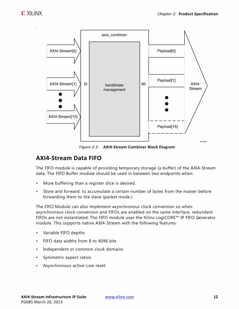
The AXI4-Stream Combiner provides a solution for aggregating multiple narrow inbound AXI4-Stream interfaces into a single wide outbound AXI4-Stream interface. Support for up to 16 inbound AXI4-Stream interfaces is provided. A block diagram of the AXI4-Stream Combiner is shown in Figure 2-3. A common use case of this solution is to merge three separate Red, Green, Blue video streams into a single RGB stream.
The combiner concatenates the incoming streams signals TDATA/TSTRB/TKEEP/TUSER to create a single output stream that is the combination of the input streams. The TLAST/TID/TDEST signals are taken from a single slave interface and the primary slave interface is configurable. All slave interfaces must assert the TVALID signal before the TVALID signal on the output is asserted.
X-Ref Target - Figure 2-2
Figure 2‐2: Clock Converter Module Block Diagram
AXI4‐Stream Infrastructure IP Suite www.xilinx.com 12PG085 March 20, 2013
Chapter 2: Product Specification
M
AXI4‐Stream Data FIFO
The FIFO module is capable of providing temporary storage (a buffer) of the AXI4-Stream data. The FIFO Buffer module should be used in between two endpoints when:
• More buffering than a register slice is desired.
• Store and forward: to accumulate a certain number of bytes from the master before forwarding them to the slave (packet mode.)
The FIFO Module can also implement asynchronous clock conversion so when asynchronous clock conversion and FIFOs are enabled on the same interface, redundant FIFOs are not instantiated. The FIFO module uses the Xilinx LogiCORE™ IP FIFO Generator module. This supports native AXI4-Stream with the following features:
• Variable FIFO depths
• FIFO data widths from 8 to 4096 bits
• Independent or common clock domains
• Symmetric aspect ratios
• Asynchronous active-Low reset
X-Ref Target - Figure 2-3
Figure 2‐3: AXI4‐Stream Combiner Block Diagram
AXI4‐Stream Infrastructure IP Suite www.xilinx.com 13PG085 March 20, 2013
Chapter 2: Product Specification
• Selectable memory type. The memory type is inferred as distributed RAM for depths of 32 or less and block RAM for all others.
• Operates in First-Word Fall-Through mode (FWFT)
• Occupancy interface
• Both FIFO Generator rd_data_count and wr_data_count are passed as separate outputs synchronized to the read side and write side clock domains.
AXI4‐Stream Data Width Converter
Data width converters (upsizer/downsizer) are required when interfacing different data width cores with each other. One data width conversion module is available to handle all supported combinations of data widths.
The conversion follows the AMBA® AXI4-Stream Protocol Specification with regards to ordering and expansion of TUSER bits. The width converter does not process any special TUSER encoding formats; it only maps TUSER bits across the width conversion function using the algorithm specified in the AXI4-Stream protocol specif ication. Depending on the usage/meaning of TUSER to the endpoint IP, additional external logic might be required to manipulate TUSER bits that have been transformed by the width converter. The number of TUSER bits per TDATA bytes must remain constant between input and output.
Up-conversion requires that each incoming beat that is composed of the new larger beat consists of identical TID and TDEST bits and no intermediate TLAST assertions. Partial data may be flushed when either the TLAST bit is received or TID/TDEST changes before enough data is accumulated to send out a complete beat. Unassigned bytes are flushed out as null bytes.
RECOMMENDED: Monitor the TKEEP signal output if TID/TDEST/TLAST signal is present.
Any non-integer multiple byte ratio conversion (N:M) is accomplished by calculating the lowest common multiple (LCM) of N and M and then up-converting from N:LCM then down-converting from LCM:M.
Up-conversion features:
• Range: Input 1-256 Bytes, Output 2-512 Bytes
• Supports full range of 1:N byte ratio conversions
• Minimum latency of 2 + N clock cycles in 1:N byte ratio up-conversion.
Down-conversion features:
• Range: Input 2-512 bytes, output 256-1 bytes
• Supports full range of N:1 byte ratio conversions
AXI4‐Stream Infrastructure IP Suite www.xilinx.com 14PG085 March 20, 2013
Chapter 2: Product Specification
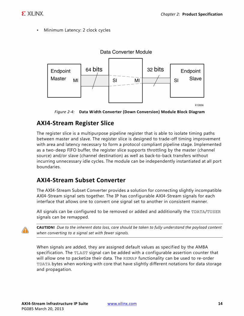
• Minimum Latency: 2 clock cycles
AXI4‐Stream Register Slice
The register slice is a multipurpose pipeline register that is able to isolate timing paths between master and slave. The register slice is designed to trade-off timing improvement with area and latency necessary to form a protocol compliant pipeline stage. Implemented as a two-deep FIFO buffer, the register slice supports throttling by the master (channel source) and/or slave (channel destination) as well as back-to-back transfers without incurring unnecessary idle cycles. The module can be independently instantiated at all port boundaries.
AXI4‐Stream Subset Converter
The AXI4-Stream Subset Converter provides a solution for connecting slightly incompatible AXI4-Stream signal sets together. The IP has configurable AXI4-Stream signals for each interface that allows one to convert one signal set to another in consistent manner.
All signals can be configured to be removed or added and additionally the TDATA/TUSER signals can be remapped.
CAUTION! Due to the inherent data loss, care should be taken to fully understand the payload content when converting to a signal set with fewer signals.
When signals are added, they are assigned default values as specif ied by the AMBA specification. The TLAST signal can be added with a configurable assertion counter that will allow one to packetize their data. The REMAP functionality can be used to re-order TDATA bytes when working with core that have slightly different notations for data storage and propagation.
X-Ref Target - Figure 2-4
Figure 2‐4: Data Width Converter (Down Conversion) Module Block Diagram
AXI4‐Stream Infrastructure IP Suite www.xilinx.com 15PG085 March 20, 2013
Chapter 2: Product Specification
AXI4‐Stream Switch
The AXI4-Stream Switch supports 1:N, M:1 and M:N configurations. It connects up to 16 masters to 16 slaves. The AXI4-Stream TDEST signaling is required for 1:N and M:N configurations.
The AXI4-Stream Switch only supports static routing through f ixed base-high TDEST ranges for each MI. A single TDEST map applies to all MI. Each MI is arbitrated independently (slave side arbitration). The AXI4-Stream Switch performs SI-side parallel decoding. Unmapped TDEST transfers will signal a decode error and drop the transfer.
The internal arbiter can perform fixed priority arbitration or round robin arbitration. The Arbiter/Switch can arbitrate on a per transfer basis or at packet boundaries (signaled by TLAST or after a configurable number of active or idle transfers.)
StandardsThe IP cores have bus interfaces that comply with the ARM® AMBA AXI4-Stream Protocol Specif ication Version 1.0.
PerformanceThe performance of an AXI4-Stream Infrastructure IP core is limited only by the FPGA fabric speed. Each core utilizes only block RAMs, LUTs, and registers and contains no I/O elements. The values presented in this section should be used as an estimation guideline, actual performance can vary.
Maximum Frequencies
Each core is designed to meet the maximum target frequency of 250 MHz on a Kintex™-7 FPGA (xc7k325tffg900-1.) It can be expected that an -2 speed grade part can achieve 5% higher maximum target frequency and that a -3 speed grade part can achieve 10% higher maximum target frequency. For AXI4-Stream Switch configurations with more than approximately four masters or slaves, the target maximum frequency can be reduced by 20-25%.
Latency
The latency in the IP cores can vary on an interface-to-interface basis, depending on how the IP cores are configured. The latency is calculated in clocked cycles and is measured as the time that it takes from the assertion of the slave interface TVALID signal to the first
AXI4‐Stream Infrastructure IP Suite www.xilinx.com 16PG085 March 20, 2013
Chapter 2: Product Specification
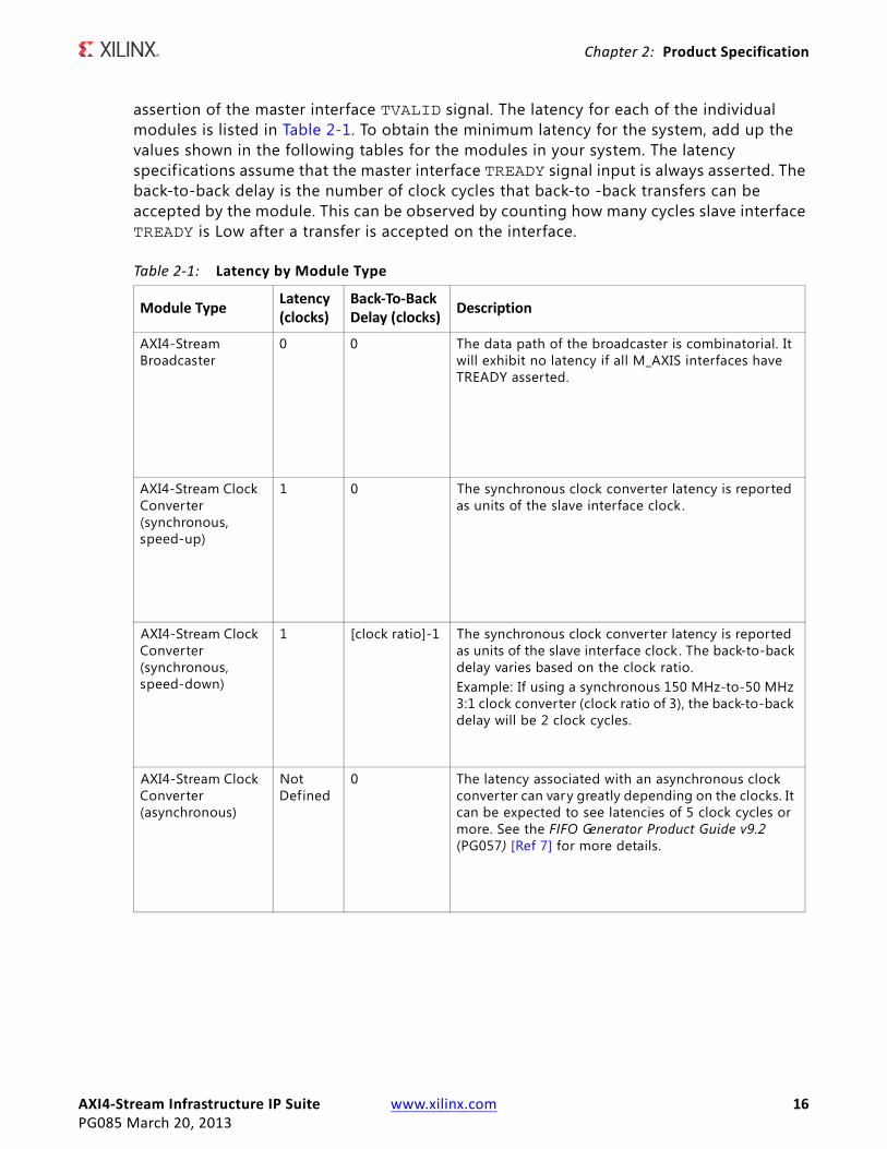
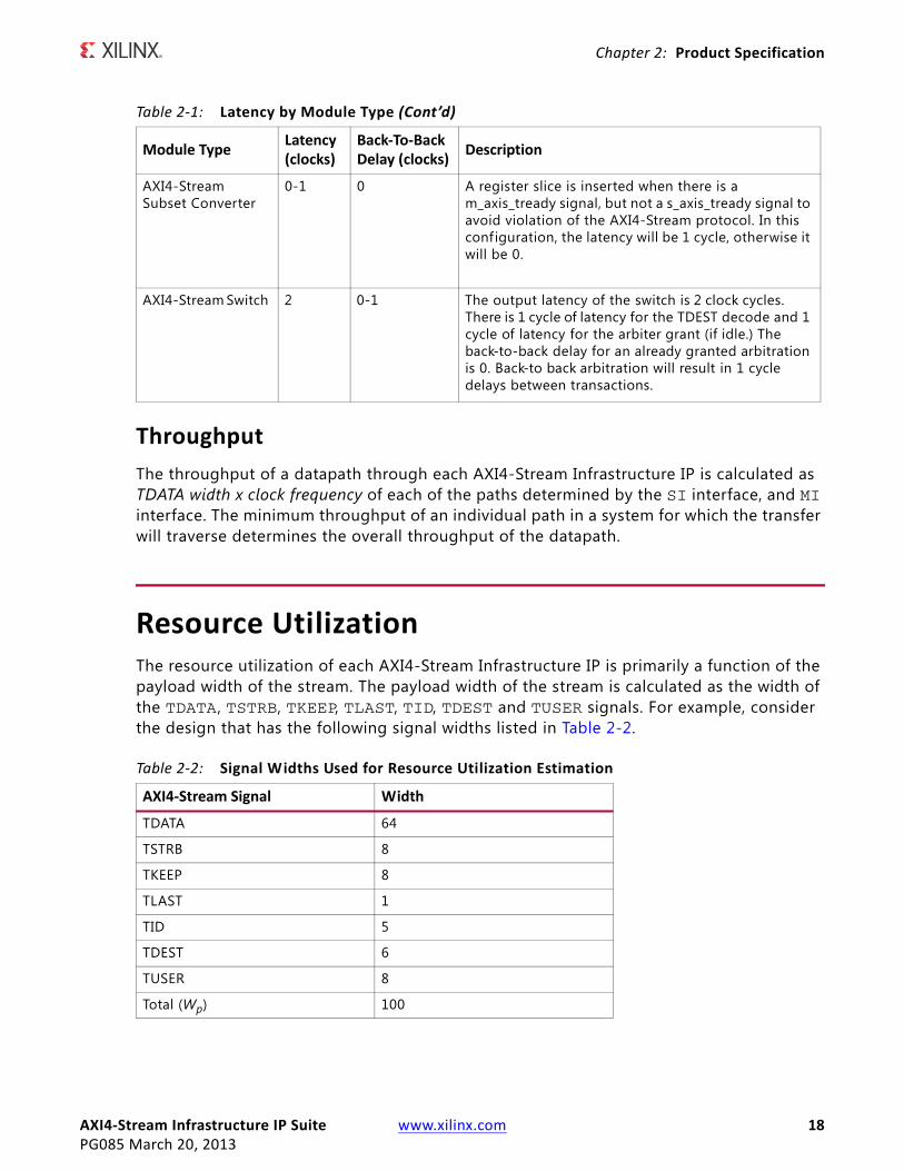
assertion of the master interface TVALID signal. The latency for each of the individual modules is listed in Table 2-1. To obtain the minimum latency for the system, add up the values shown in the following tables for the modules in your system. The latency specifications assume that the master interface TREADY signal input is always asserted. The back-to-back delay is the number of clock cycles that back-to -back transfers can be accepted by the module. This can be observed by counting how many cycles slave interface TREADY is Low after a transfer is accepted on the interface.
Table 2‐1: Latency by Module Type
Module TypeLatency (clocks)
Back‐To‐Back Delay (clocks)
Description
AXI4-Stream Broadcaster
0 0 The data path of the broadcaster is combinatorial. It will exhibit no latency if all M_AXIS interfaces have TREADY asserted.
AXI4-Stream Clock Converter (synchronous, speed-up)
1 0 The synchronous clock converter latency is reported as units of the slave interface clock .
AXI4-Stream Clock Converter (synchronous, speed-down)
1 [clock ratio]-1 The synchronous clock converter latency is reported as units of the slave interface clock . The back-to-back delay varies based on the clock ratio.Example: If using a synchronous 150 MHz-to-50 MHz 3:1 clock converter (clock ratio of 3), the back-to-back delay will be 2 clock cycles.
AXI4-Stream Clock Converter (asynchronous)
Not Defined
0 The latency associated with an asynchronous clock converter can vary greatly depending on the clocks. It can be expected to see latencies of 5 clock cycles or more. See the FIFO Generator Product Guide v9.2 (PG057) [Ref 7] for more details.
AXI4‐Stream Infrastructure IP Suite www.xilinx.com 17PG085 March 20, 2013
Chapter 2: Product Specification
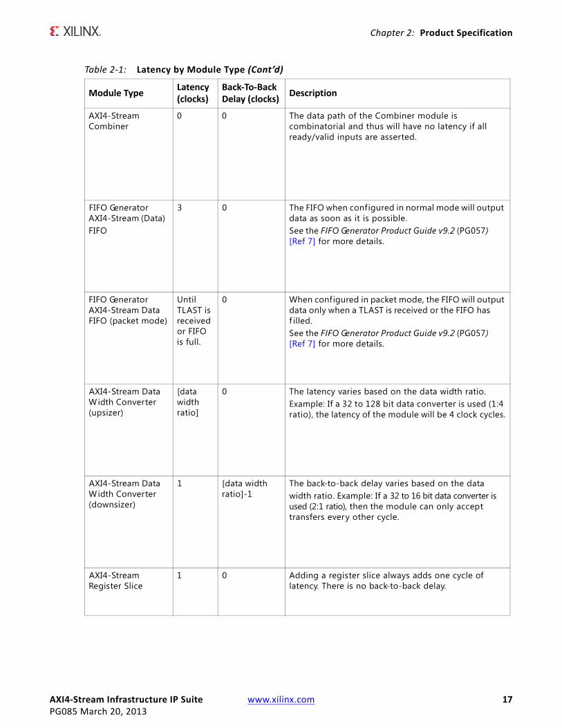
AXI4-Stream Combiner
0 0 The data path of the Combiner module is combinatorial and thus will have no latency if all ready/valid inputs are asserted.
FIFO Generator AXI4-Stream (Data)FIFO
3 0 The FIFO when configured in normal mode will output data as soon as it is possible.See the FIFO Generator Product Guide v9.2 (PG057) [Ref 7] for more details.
FIFO Generator AXI4-Stream Data FIFO (packet mode)
Until TLAST is received or FIFO is full.
0 When configured in packet mode, the FIFO will output data only when a TLAST is received or the FIFO has f illed.See the FIFO Generator Product Guide v9.2 (PG057) [Ref 7] for more details.
AXI4-Stream Data Width Converter (upsizer)
[data width ratio]
0 The latency varies based on the data width ratio. Example: If a 32 to 128 bit data converter is used (1:4 ratio), the latency of the module will be 4 clock cycles.
AXI4-Stream Data Width Converter (downsizer)
1 [data width ratio]-1
The back-to-back delay varies based on the datawidth ratio. Example: If a 32 to 16 bit data converter is used (2:1 ratio), then the module can only accept transfers every other cycle.
AXI4-Stream Register Slice
1 0 Adding a register slice always adds one cycle of latency. There is no back-to-back delay.
Table 2‐1: Latency by Module Type (Cont’d)
Module TypeLatency (clocks)
Back‐To‐Back Delay (clocks)
Description
AXI4‐Stream Infrastructure IP Suite www.xilinx.com 18PG085 March 20, 2013
Chapter 2: Product Specification
Throughput
The throughput of a datapath through each AXI4-Stream Infrastructure IP is calculated as TDATA width x clock frequency of each of the paths determined by the SI interface, and MI interface. The minimum throughput of an individual path in a system for which the transfer will traverse determines the overall throughput of the datapath.
Resource UtilizationThe resource utilization of each AXI4-Stream Infrastructure IP is primarily a function of the payload width of the stream. The payload width of the stream is calculated as the width of the TDATA , TSTRB, TKEEP, TLAST, TID, TDEST and TUSER signals. For example, consider the design that has the following signal widths listed in Table 2-2.
AXI4-Stream Subset Converter
0-1 0 A register slice is inserted when there is a m_axis_tready signal, but not a s_axis_tready signal to avoid violation of the AXI4-Stream protocol. In this configuration, the latency will be 1 cycle, otherwise it will be 0.
AXI4-Stream Switch 2 0-1 The output latency of the switch is 2 clock cycles. There is 1 cycle of latency for the TDEST decode and 1 cycle of latency for the arbiter grant (if idle.) The back-to-back delay for an already granted arbitration is 0. Back-to back arbitration will result in 1 cycle delays between transactions.
Table 2‐2: Signal Widths Used for Resource Utilization Estimation
AXI4‐Stream Signal Width
TDATA 64
TSTRB 8
TKEEP 8
TLAST 1
TID 5
TDEST 6
TUSER 8
Total (Wp) 100
Table 2‐1: Latency by Module Type (Cont’d)
Module TypeLatency (clocks)
Back‐To‐Back Delay (clocks)
Description
AXI4‐Stream Infrastructure IP Suite www.xilinx.com 19PG085 March 20, 2013
Chapter 2: Product Specification
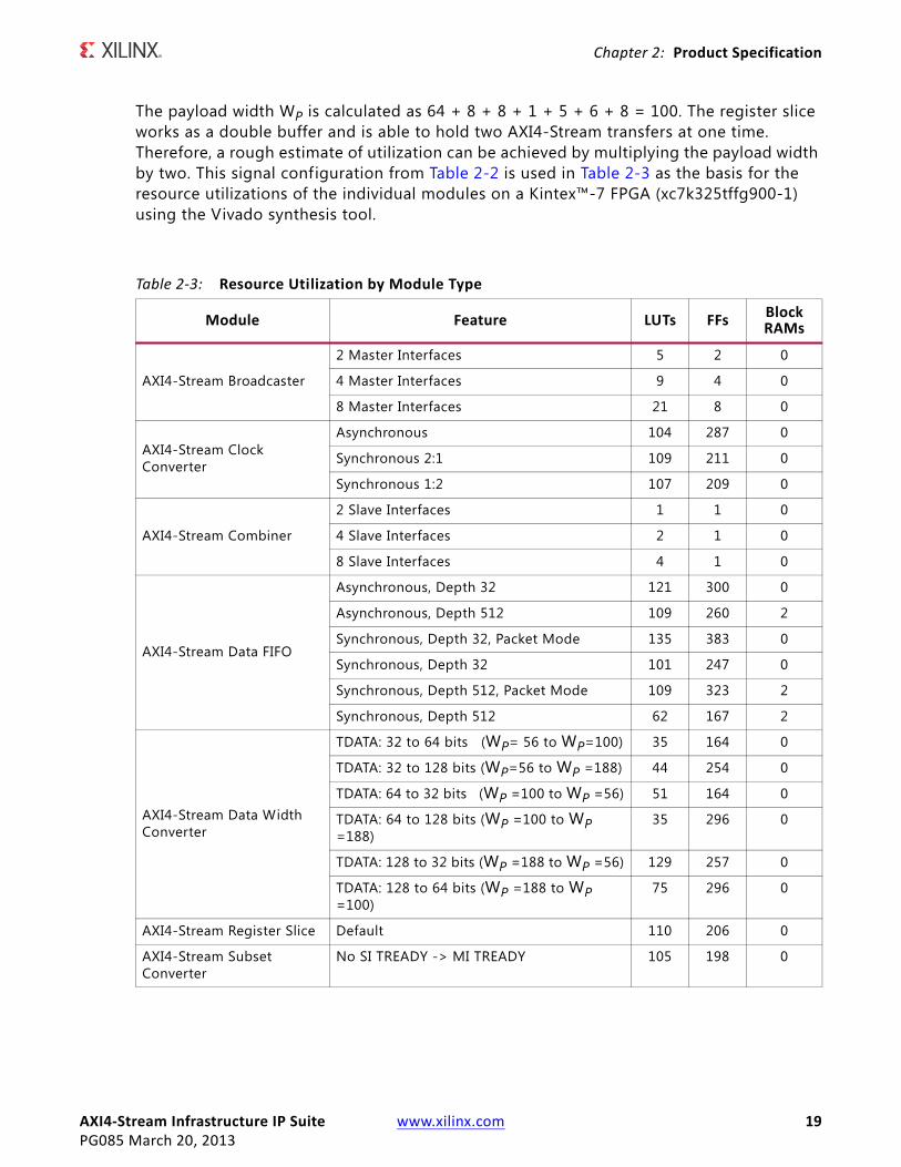
The payload width WP is calculated as 64 + 8 + 8 + 1 + 5 + 6 + 8 = 100. The register slice works as a double buffer and is able to hold two AXI4-Stream transfers at one time. Therefore, a rough estimate of utilization can be achieved by multiplying the payload width by two. This signal configuration from Table 2-2 is used in Table 2-3 as the basis for the resource utilizations of the individual modules on a Kintex™-7 FPGA (xc7k325tffg900-1) using the Vivado synthesis tool.
Table 2‐3: Resource Utilization by Module Type
Module Feature LUTs FFs Block RAMs
AXI4-Stream Broadcaster
2 Master Interfaces 5 2 0
4 Master Interfaces 9 4 0
8 Master Interfaces 21 8 0
AXI4-Stream Clock Converter
Asynchronous 104 287 0
Synchronous 2:1 109 211 0
Synchronous 1:2 107 209 0
AXI4-Stream Combiner
2 Slave Interfaces 1 1 0
4 Slave Interfaces 2 1 0
8 Slave Interfaces 4 1 0
AXI4-Stream Data FIFO
Asynchronous, Depth 32 121 300 0
Asynchronous, Depth 512 109 260 2
Synchronous, Depth 32, Packet Mode 135 383 0
Synchronous, Depth 32 101 247 0
Synchronous, Depth 512, Packet Mode 109 323 2
Synchronous, Depth 512 62 167 2
AXI4-Stream Data Width Converter
TDATA: 32 to 64 bits (WP= 56 to WP=100) 35 164 0
TDATA: 32 to 128 bits (WP=56 to WP =188) 44 254 0
TDATA: 64 to 32 bits (WP =100 to WP =56) 51 164 0
TDATA: 64 to 128 bits (WP =100 to WP =188)
35 296 0
TDATA: 128 to 32 bits (WP =188 to WP =56) 129 257 0
TDATA: 128 to 64 bits (WP =188 to WP =100)
75 296 0
AXI4-Stream Register Slice Default 110 206 0
AXI4-Stream Subset Converter
No SI TREADY -> MI TREADY 105 198 0
AXI4‐Stream Infrastructure IP Suite www.xilinx.com 20PG085 March 20, 2013
Chapter 2: Product Specification
Port Descriptions
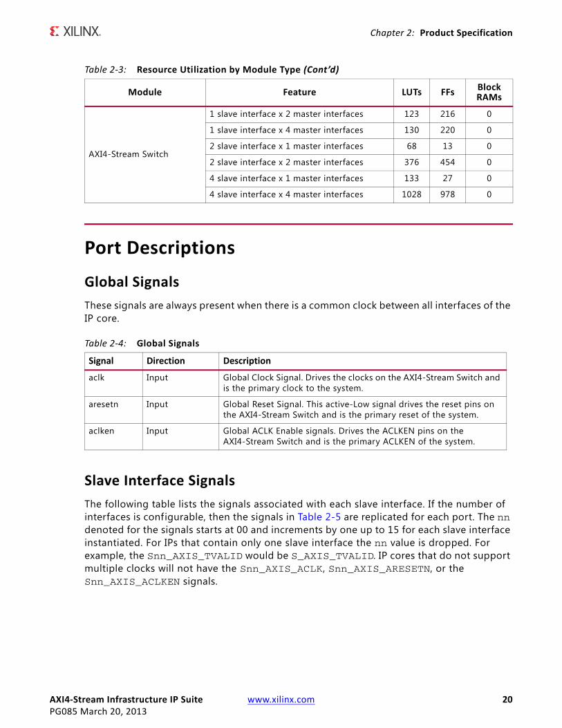
Global Signals
These signals are always present when there is a common clock between all interfaces of the IP core.
Slave Interface Signals
The following table lists the signals associated with each slave interface. If the number of interfaces is configurable, then the signals in Table 2-5 are replicated for each port. The nn denoted for the signals starts at 00 and increments by one up to 15 for each slave interface instantiated. For IPs that contain only one slave interface the nn value is dropped. For example, the Snn_AXIS_TVALID would be S_AXIS_TVALID. IP cores that do not support multiple clocks will not have the Snn_AXIS_ACLK, Snn_AXIS_ARESETN, or the Snn_AXIS_ACLKEN signals.
AXI4-Stream Switch
1 slave interface x 2 master interfaces 123 216 0
1 slave interface x 4 master interfaces 130 220 0
2 slave interface x 1 master interfaces 68 13 0
2 slave interface x 2 master interfaces 376 454 0
4 slave interface x 1 master interfaces 133 27 0
4 slave interface x 4 master interfaces 1028 978 0
Table 2‐4: Global Signals
Signal Direction Description
aclk Input Global Clock Signal. Drives the clocks on the AXI4-Stream Switch and is the primary clock to the system.
aresetn Input Global Reset Signal. This active-Low signal drives the reset pins on the AXI4-Stream Switch and is the primary reset of the system.
aclken Input Global ACLK Enable signals. Drives the ACLKEN pins on the AXI4-Stream Switch and is the primary ACLKEN of the system.
Table 2‐3: Resource Utilization by Module Type (Cont’d)
Module Feature LUTs FFs Block RAMs
AXI4‐Stream Infrastructure IP Suite www.xilinx.com 21PG085 March 20, 2013
Chapter 2: Product Specification
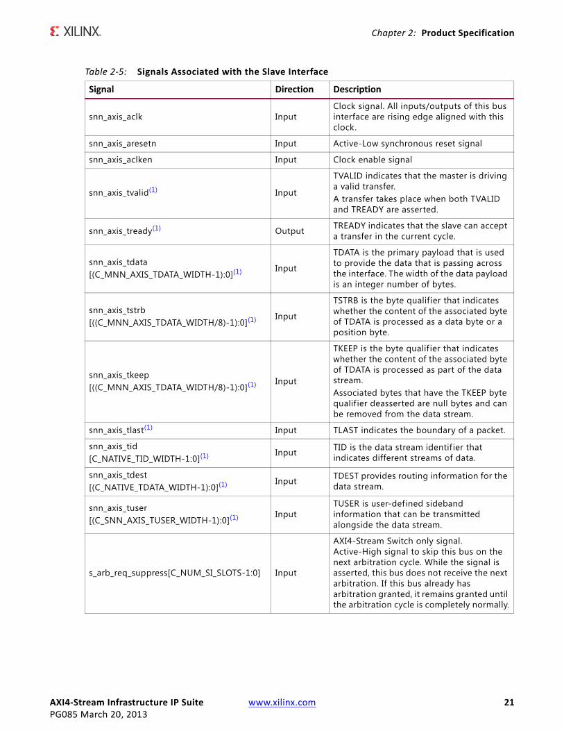
Table 2‐5: Signals Associated with the Slave Interface
Signal Direction Description
snn_axis_aclk InputClock signal. All inputs/outputs of this bus interface are rising edge aligned with this clock.
snn_axis_aresetn Input Active-Low synchronous reset signal
snn_axis_aclken Input Clock enable signal
snn_axis_tvalid(1) Input
TVALID indicates that the master is driving a valid transfer.A transfer takes place when both TVALID and TREADY are asserted.
snn_axis_tready(1) Output TREADY indicates that the slave can accept a transfer in the current cycle.
snn_axis_tdata[(C_MNN_AXIS_TDATA_WIDTH-1):0](1) Input
TDATA is the primary payload that is used to provide the data that is passing across the interface. The width of the data payload is an integer number of bytes.
snn_axis_tstrb[((C_MNN_AXIS_TDATA_WIDTH/8)-1):0](1) Input
TSTRB is the byte qualif ier that indicates whether the content of the associated byte of TDATA is processed as a data byte or a position byte.
snn_axis_tkeep[((C_MNN_AXIS_TDATA_WIDTH/8)-1):0](1) Input
TKEEP is the byte qualif ier that indicates whether the content of the associated byte of TDATA is processed as part of the data stream.Associated bytes that have the TKEEP byte qualif ier deasserted are null bytes and can be removed from the data stream.
snn_axis_tlast(1) Input TLAST indicates the boundary of a packet.
snn_axis_tid[C_NATIVE_TID_WIDTH-1:0](1) Input TID is the data stream identif ier that
indicates different streams of data.
snn_axis_tdest[(C_NATIVE_TDATA_WIDTH-1):0](1) Input TDEST provides routing information for the
data stream.
snn_axis_tuser[(C_SNN_AXIS_TUSER_WIDTH-1):0](1) Input
TUSER is user-defined sideband information that can be transmitted alongside the data stream.
s_arb_req_suppress[C_NUM_SI_SLOTS-1:0] Input
AXI4-Stream Switch only signal. Active-High signal to skip this bus on the next arbitration cycle. While the signal is asserted, this bus does not receive the next arbitration. If this bus already has arbitration granted, it remains granted until the arbitration cycle is completely normally.
AXI4‐Stream Infrastructure IP Suite www.xilinx.com 22PG085 March 20, 2013
Chapter 2: Product Specification
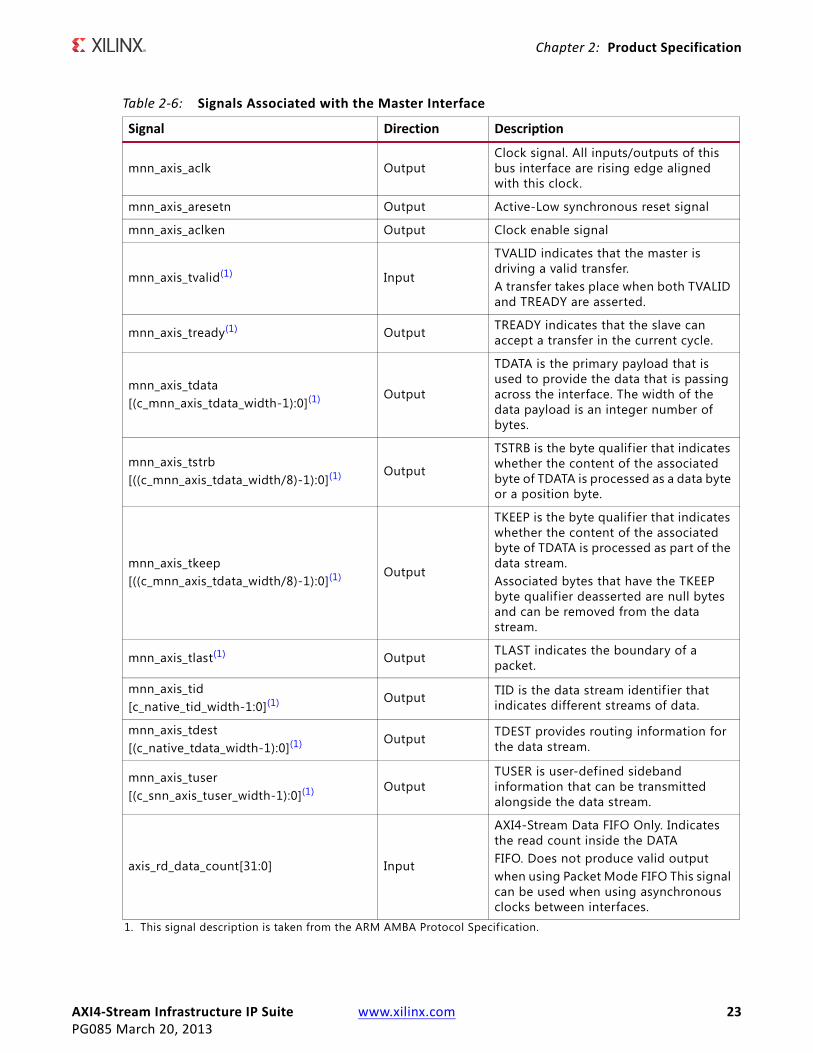
Master Interface Signals
Table 2-6 lists the signals associated with each master interface. If the number of interfaces is configurable, the signals are then replicated for each port. The nn denoted for the signals starts at 00 and increments by one up to 15 for each master interface instantiated. For IPs that contain only one master interface the nn value is dropped. For example, the Mnn_AXIS_TVALID would be M_AXIS_TVALID. IPs that do not support multiple clocks will not have the Mnn_AXIS_ACLK, Mnn_AXIS_ARESETN, or the Mnn_AXIS_ACLKEN signals.
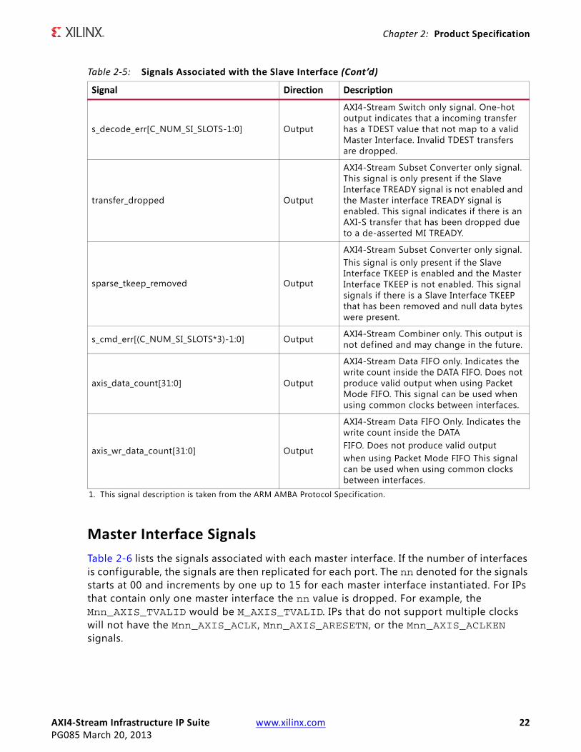
s_decode_err[C_NUM_SI_SLOTS-1:0] Output
AXI4-Stream Switch only signal. One-hot output indicates that a incoming transfer has a TDEST value that not map to a valid Master Interface. Invalid TDEST transfers are dropped.
transfer_dropped Output
AXI4-Stream Subset Converter only signal. This signal is only present if the Slave Interface TREADY signal is not enabled and the Master interface TREADY signal is enabled. This signal indicates if there is an AXI-S transfer that has been dropped due to a de-asserted MI TREADY.
sparse_tkeep_removed Output
AXI4-Stream Subset Converter only signal.This signal is only present if the Slave Interface TKEEP is enabled and the Master Interface TKEEP is not enabled. This signal signals if there is a Slave Interface TKEEP that has been removed and null data bytes were present.
s_cmd_err[(C_NUM_SI_SLOTS*3)-1:0] Output AXI4-Stream Combiner only. This output is not defined and may change in the future.
axis_data_count[31:0] Output
AXI4-Stream Data FIFO only. Indicates the write count inside the DATA FIFO. Does not produce valid output when using Packet Mode FIFO. This signal can be used when using common clocks between interfaces.
axis_wr_data_count[31:0] Output
AXI4-Stream Data FIFO Only. Indicates the write count inside the DATAFIFO. Does not produce valid outputwhen using Packet Mode FIFO This signal can be used when using common clocks between interfaces.
1. This signal description is taken from the ARM AMBA Protocol Specif ication.
Table 2‐5: Signals Associated with the Slave Interface (Cont’d)
Signal Direction Description
AXI4‐Stream Infrastructure IP Suite www.xilinx.com 23PG085 March 20, 2013
Chapter 2: Product Specification
Table 2‐6: Signals Associated with the Master Interface
Signal Direction Description
mnn_axis_aclk OutputClock signal. All inputs/outputs of this bus interface are rising edge aligned with this clock.
mnn_axis_aresetn Output Active-Low synchronous reset signal
mnn_axis_aclken Output Clock enable signal
mnn_axis_tvalid(1) Input
TVALID indicates that the master is driving a valid transfer.A transfer takes place when both TVALID and TREADY are asserted.
mnn_axis_tready(1) Output TREADY indicates that the slave can accept a transfer in the current cycle.
mnn_axis_tdata[(c_mnn_axis_tdata_width-1):0](1) Output
TDATA is the primary payload that is used to provide the data that is passing across the interface. The width of the data payload is an integer number of bytes.
mnn_axis_tstrb[((c_mnn_axis_tdata_width/8)-1):0](1) Output
TSTRB is the byte qualif ier that indicates whether the content of the associated byte of TDATA is processed as a data byte or a position byte.
mnn_axis_tkeep[((c_mnn_axis_tdata_width/8)-1):0](1) Output
TKEEP is the byte qualif ier that indicates whether the content of the associated byte of TDATA is processed as part of the data stream.Associated bytes that have the TKEEP byte qualif ier deasserted are null bytes and can be removed from the data stream.
mnn_axis_tlast(1) Output TLAST indicates the boundary of a packet.
mnn_axis_tid[c_native_tid_width-1:0](1) Output TID is the data stream identif ier that
indicates different streams of data.
mnn_axis_tdest[(c_native_tdata_width-1):0](1) Output TDEST provides routing information for
the data stream.
mnn_axis_tuser[(c_snn_axis_tuser_width-1):0](1) Output
TUSER is user-defined sideband information that can be transmitted alongside the data stream.
axis_rd_data_count[31:0] Input
AXI4-Stream Data FIFO Only. Indicates the read count inside the DATAFIFO. Does not produce valid outputwhen using Packet Mode FIFO This signal can be used when using asynchronous clocks between interfaces.
1. This signal description is taken from the ARM AMBA Protocol Specif ication.
AXI4‐Stream Infrastructure IP Suite www.xilinx.com 24PG085 March 20, 2013
Chapter 3
Designing with the CoreThis chapter includes guidelines and additional information to make designing with the core easier.
General Design GuidelinesWhen designing systems using AXI4-Stream Infrastructure IP Suite, the f irst step is to establish the topology of the system. This requires an understanding of the main interface characteristics of each AXI4-Stream master and slave that needs to be able to communicate together. AXI4-Stream masters and slaves then need to be grouped by desired connectivity into a system with one or more AXI4-Stream Infrastructure IP blocks tying them together so they can exchange data.
In general, try to establish the system partitioning/topology to use multiple smaller/simpler interconnects than a single large interconnect, especially in systems with a large number of devices. For example, combinations of N master x 1 slaves interconnects and 1 master x N slave interconnects are generally preferable to MxN interconnects in terms of area, latency, and throughput. MxN interconnect when required for performance or connectivity requirements should try to limit the number of endpoints or specify sparse connectivity to reduce resource utilization.
The Xilinx AXI Reference Guide (UG761) [Ref 3] provides information about AXI4-Stream protocol usage guidelines and conventions; much of the AXI system optimizations information described for AXI Interconnect is applicable to AXI4-Stream Infrastructure IP Suite. The Xilinx AXI Reference Guide should be reviewed and consulted before designing or structuring systems around the AXI4-Stream Infrastructure IP.
After the number and topology of AXI4-Stream Infrastructure IP systems have been determined, the next step is to tailor each AXI4-Stream Infrastructure IP system to have the correct set of optional interface signals and set signals’ widths as needed. This sets up the interface signal set for the AXI4-Stream Infrastructure IP to ensure that data can be exchanged and routed as needed across the system.
Finally, the AXI4-Stream Infrastructure IP system should be optimized and fine-tuned to fit its application. This includes tuning FIFOs, width converters, clock converters, arbiters, and register slices (pipeline stages) as needed to balance area, timing, performance, and ease-of-use.
AXI4‐Stream Infrastructure IP Suite www.xilinx.com 25PG085 March 20, 2013
Chapter 3: Designing with the Core
ClockingEach AXI4-Stream Infrastructure IP module has a single clock input that must be driven with the exception of AXI4-Stream Clock Converter and AXI4-Stream Data FIFO. These modules allow for different clocks and must have both S_AXIS_ACLK and M_AXIS_ACLK connected.
The AXI4-Stream Clock Converter and Data FIFO allows systems with different clock domains to be designed. AXI4-Stream Clock Converter synchronous mode can be used when the endpoint IP has a phase-aligned, integer multiple clock ratio to the core switch's clock. This is often the case when the same MMCM or PLL is driving synchronous integer ratio clocks because the MMCM/PLL can also ensure phase alignment across their clock outputs. The AXI4-Stream Clock Converter and AXI4-Stream Data FIFO asynchronous clocking mode allows the attached endpoint IP to run at a completely unrelated clock frequency or phase to the core switch clock. Embedded asynchronous FIFOs from FIFO Generator are instantiated inside the modules to handle data transfers across asynchronous clock domains in a robust manner.
An optional feature for clock enables (ACLKEN ports) allows an extra level of control for essentially gating clocks. The clock enable signals can be used to control which clock edges are seen as real transfer cycles. Clock enables can be used for purposes like preserving global clock buffers, debug by stepping the clock enable to step through operational states in the system, and dynamic power savings. Clock enables can be controlled independently on each interface port and for the core switch.
AXI4‐Stream Infrastructure IP Suite www.xilinx.com 26PG085 March 20, 2013
Chapter 3: Designing with the Core
ResetsThe AXI4-Stream Infrastructure IP Suite provides active-Low reset inputs for every clock input on the IP. Each reset input must be synchronized to the associated ACLK input of the interface. To ensure data is not lost during reset de-assertion across multiple interfaces of the AXI4-Stream Infrastructure IP systems (operating in potentially different clock domains), the AXI4-Stream Infrastructure IP will de-assert all TREADY and TVALID outputs until the clock cycle after their source logic has internally exited reset. Any endpoint IP driving TREADY or TVALID inputs to the AXI4-Stream Infrastructure IP should also de-assert these signals until the clock cycle after they have exited reset internally.
These guidelines ensure that endpoint IPs can internally come out of reset at different times (due to internal reset pipelining) and no data will be exchanged until both are internally out of reset.
RECOMMENDED: Any endpoint should de-assert TREADY and TVALID within 8 clock cycles of reset assertion. ARESETn should also be asserted for at least 16 cycles of the slowest system clock to ensure that all AXI4-Stream interfaces in the system enter reset and have time to de-assert their TREADY/TVALID outputs before coming back out of reset.
AXI4‐Stream Infrastructure IP Suite www.xilinx.com 27PG085 March 20, 2013
Chapter 4
Customizing and Generating the CoreThis chapter includes information on using Xilinx tools to customize and generate the core using the Vivado™ IP Catalog.
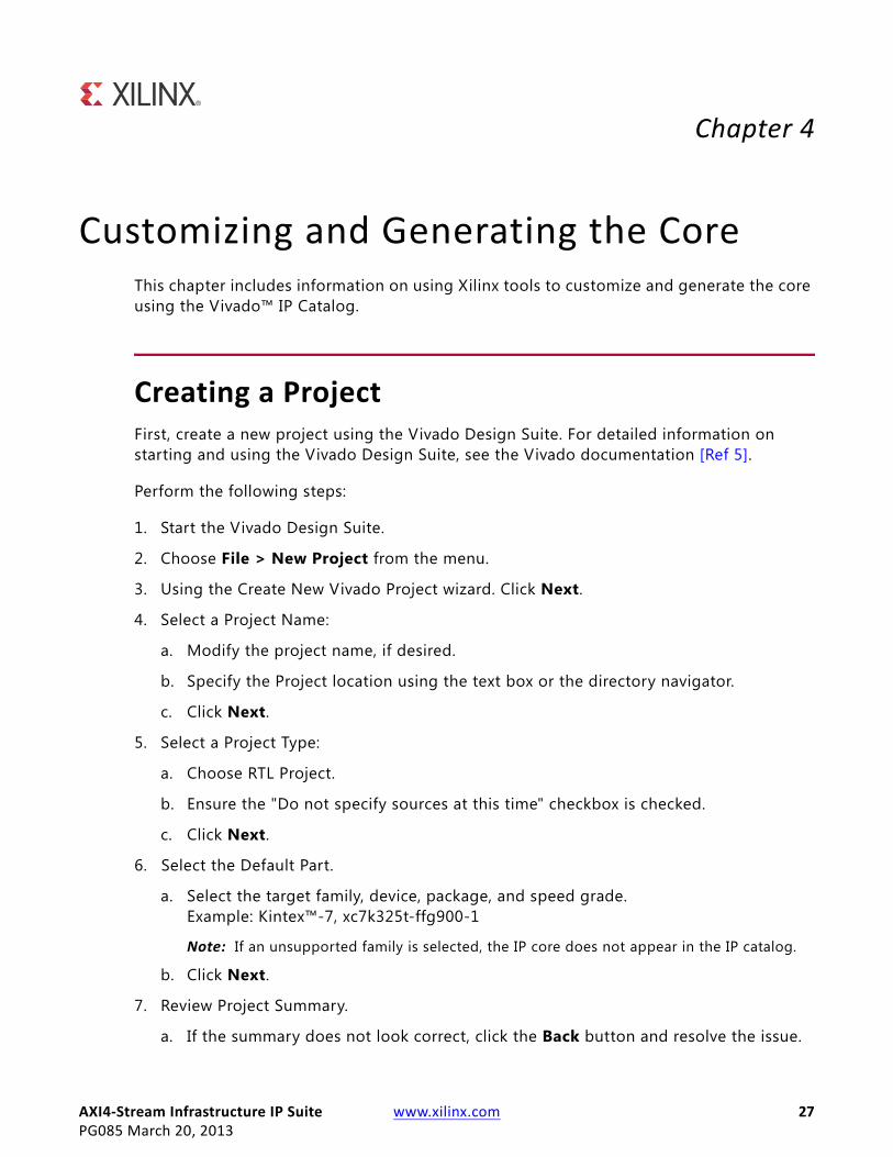
Creating a Project First, create a new project using the Vivado Design Suite. For detailed information on starting and using the Vivado Design Suite, see the Vivado documentation [Ref 5].
Perform the following steps:
1. Start the Vivado Design Suite.
2. Choose File > New Project from the menu.
3. Using the Create New Vivado Project wizard. Click Next.
4. Select a Project Name:
a. Modify the project name, if desired.
b. Specify the Project location using the text box or the directory navigator.
c. Click Next.
5. Select a Project Type:
a. Choose RTL Project.
b. Ensure the "Do not specify sources at this time" checkbox is checked.
c. Click Next.
6. Select the Default Part.
a. Select the target family, device, package, and speed grade.Example: Kintex™-7, xc7k325t-ffg900-1
Note: If an unsupported family is selected, the IP core does not appear in the IP catalog.
b. Click Next.
7. Review Project Summary.
a. If the summary does not look correct, click the Back button and resolve the issue.
AXI4‐Stream Infrastructure IP Suite www.xilinx.com 28PG085 March 20, 2013
Chapter 4: Customizing and Generating the Core
b. Click Finish to create the project.
After creating the project, the IP cores are available for selection in the IP catalog, located at AXI Infrastructure Taxonomy.
Customizing and Generating the Core Locate the IP core in the Vivado Design Suite and click it once to select it. Details regarding the solution are displayed in the Details window. To configure the IP, double-click the IP name in the IP catalog.
This launches the customization dialog box. Each dialog box is described in detail in their respective sections.
AXI4‐Stream Broadcaster
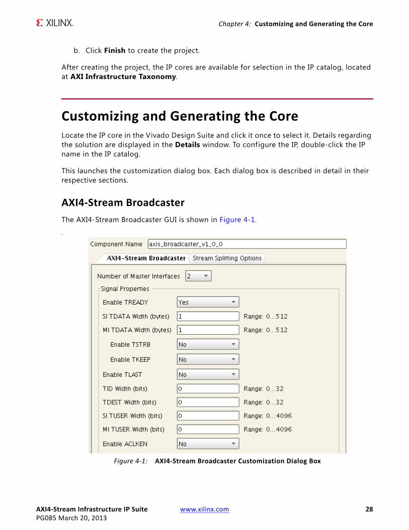
The AXI4-Stream Broadcaster GUI is shown in Figure 4-1.
MX-Ref Target - Figure 4-1
Figure 4‐1: AXI4‐Stream Broadcaster Customization Dialog Box
AXI4‐Stream Infrastructure IP Suite www.xilinx.com 29PG085 March 20, 2013
Chapter 4: Customizing and Generating the Core
Review each of the available options in Figure 4-1 and modify them as desired so that the AXI4-Stream Broadcaster solution meets the requirements of the larger project into which it is integrated. The following subsections discuss the options in detail to serve as a guide.
Global Parameters
Component Name: The base name of the output f iles generated for the core. Names must begin with a letter and can be composed of any of the following characters: a to z, 0 to 9, and "_".
Number of Master Interfaces: This parameter specifies the number of AXI4-Stream master interfaces present on the IP. The value can be 2 and 16. AXI4-Stream slave interface transfers are replicated to each of the AXI4-Stream master interfaces specified by this parameter.
Signal Properties
Enable TREADY: If set to Yes, this parameters specifies if the optional TREADY signal is present on all the AXI4-Stream interfaces. Set to No to omit the signal.
TIP: The AXI4-Stream specification recommends that TREADY is always included.
SI TDATA Width (bytes): This parameter specifies the width in bytes of the TDATA signal on the inbound AXI4-Stream Interface (the Slave Interface). This parameter is an integer and can vary from 0 to 512. Set to 0 to omit the TDATA signal. If the TDATA signal is omitted, then the TKEEP and TSTRB signals are also omitted. The width of the port will be multiplied by 8 to get the width in bits.
MI TDATA Width (bytes): This parameter specifies the width in bytes of the TDATA signal on each of the outbound AXI4-Stream Interfaces (the Master Interfaces). This parameter is an integer and can vary from 0 to 512 but it may only be set to 0 if the SI TDATA Width is also 0. When both parameters are set to 0, the TDATA signal will be omitted from the interfaces of the IP. If the TDATA signal is omitted, then the TKEEP and TSTRB signals are also omitted. The width of the TDATA signal on each port will be multiplied by 8 to get the width in bits. If the MI TDATA Width is not equal to the SI TDATA Width then TKEEP and TSTRB signals should not be enabled.
Enable TSTRB: If set to Yes, this parameters specifies if the optional TSTRB signal is present on all the AXI4-Stream interfaces. This option can only be enabled if the SI and MI TDATA width (bytes) parameter are both greater than 0 and each have the same width value.
Enable TKEEP: If set to Yes, this parameters specif ies if the optional TKEEP signal is present on all the AXI4-Stream interfaces. This option can only be enabled if the SI and MI TDATA width (bytes) parameter are both greater than 0 and each have the same width value.
Enable TLAST: If set to Yes, this parameters specif ies if the optional TLAST signal is present on all the AXI4-Stream interfaces.
AXI4‐Stream Infrastructure IP Suite www.xilinx.com 30PG085 March 20, 2013
Chapter 4: Customizing and Generating the Core
TID Width (bits): If greater than 0, this parameter specif ies if the optional TID signal is present on all the AXI4-Stream interfaces. A value of 0 will omit this signal. Values 1 and 32 will set the width of this signal accordingly.
TDEST Width (bits): If greater than 0, this parameter specif ies if the optional TDEST signal is present on all the AXI4-Stream interfaces. A value of 0 will omit this signal. Values 1 and 32 will set the width of this signal accordingly.
TUSER Width (bits): If greater than 0, this parameter specifies if the optional TUSER signal is present on all the AXI4-Stream interfaces. A value of 0 will omit this signal. Values 1 and 32 will set the width of this signal accordingly.
Enable ACLKEN: If set to Yes, this parameter specif ies if the optional ACLKEN signal is present with all the AXI4-Stream interfaces clocks.
Stream Splitting Options
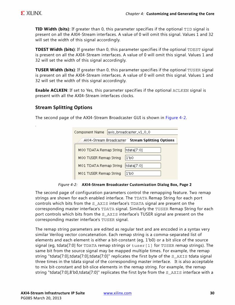
The second page of the AXI4-Stream Broadcaster GUI is shown in Figure 4-2.
M
The second page of configuration parameters control the remapping feature. Two remap strings are shown for each enabled interface. The TDATA Remap String for each port controls which bits from the S_AXIS interface's TDATA signal are present on the corresponding master interface's TDATA signal. Similarly the TUSER Remap String for each port controls which bits from the S_AXIS interface's TUSER signal are present on the corresponding master interface's TUSER signal.
The remap string parameters are edited as regular text and are encoded in a syntax very similar Verilog vector concatenation. Each remap string is a comma-separated list of elements and each element is either a bit-constant (eg, 1'b0) or a bit slice of the source signal (eg, tdata[7:0] for TDATA remap strings or tuser[1] for TUSER remap strings). The same bit from the source signal may be mapped multiple times. For example, the remap string "tdata[7:0],tdata[7:0],tdata[7:0]" replicates the f irst byte of the S_AXIS tdata signal three times in the tdata signal of the corresponding master interface. It is also acceptable to mix bit-constant and bit-slice elements in the remap string. For example, the remap string "tdata[7:0],8'b0,tdata[7:0]" replicates the f irst byte from the S_AXIS interface with a
X-Ref Target - Figure 4-2
Figure 4‐2: AXI4‐Stream Broadcaster Customization Dialog Box, Page 2
AXI4‐Stream Infrastructure IP Suite www.xilinx.com 31PG085 March 20, 2013
Chapter 4: Customizing and Generating the Core
1 byte constant in the second byte position of the corresponding master interface. The total width of the expression specif ied must match the width of the master interface signal specified in the M_TDATA_NUM_BYTES or M_TUSER_WIDTH parameter. If the S_AXIS signal width is 0 and the width of the corresponding master interface signal is greater than 0, the remap expression must be a bit-constant covering the full width of the master interface signal.
The IP configuration GUI automatically updates the remap strings to safe defaults whenever the Number of Master Interfaces, SI TDATA Width, MI TDATA Width, SI TUSER Width or MI TUSER Width parameters are changed. If any custom remap strings are to be used in the IP configuration, it is recommended the custom remap strings are entered specif ied after the above parameters have been set to their desired value.
AXI4‐Stream Clock Converter
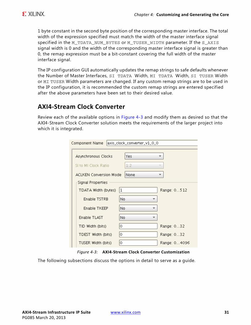
Review each of the available options in Figure 4-3 and modify them as desired so that the AXI4-Stream Clock Converter solution meets the requirements of the larger project into which it is integrated.
The following subsections discuss the options in detail to serve as a guide.
X-Ref Target - Figure 4-3
Figure 4‐3: AXI4‐Stream Clock Converter Customization
AXI4‐Stream Infrastructure IP Suite www.xilinx.com 32PG085 March 20, 2013
Chapter 4: Customizing and Generating the Core
Global Parameters
Component Name
The base name of the output f iles generated for the core. Names must begin with a letter and can be composed of any of the following characters: a to z, 0 to 9, and "_".
Asynchronous Clocks
If set to Yes, then the S_AXIS_ACLK and M_AXIS_ACLK clock signals are assumed to be asynchronous to each other and the IP operates in asynchronous mode. The Slave Interface Clock Frequency Ratio and Master Interface Clock Frequency Ratio options are disabled when the clocks are specif ied as asynchronous. Asynchronous clock mode should be used unless S_AXIS_ACLK and M_AXIS_ACLK are phase aligned and have frequencies that have either 1:N or N:1 clock frequency ratio.
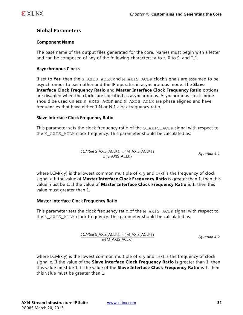
Slave Interface Clock Frequency Ratio
This parameter sets the clock frequency ratio of the S_AXIS_ACLK signal with respect to the M_AXIS_ACLK clock frequency. This parameter should be calculated as:
Equation 4‐1
where LCM(x,y) is the lowest common multiple of x, y and (x) is the frequency of clock signal x. If the value of Master Interface Clock Frequency Ratio is greater than 1, then this value must be 1. If the value of Master Interface Clock Frequency Ratio is 1, then this value must greater than 1.
Master Interface Clock Frequency Ratio
This parameter sets the clock frequency ratio of the M_AXIS_ACLK signal with respect to the S_AXIS_ACLK clock frequency. This parameter should be calculated as:
Equation 4‐2
where LCM(x,y) is the lowest common multiple of x, y and (x) is the frequency of clock signal x. If the value of the Slave Interface Clock Frequency Ratio is greater than 1, then this value must be 1. If the value of the Slave Interface Clock Frequency Ratio is 1, then this value must be greater than 1.
LCM( S_AXIS_ACLK , M_AXIS_ACLK S_AXIS_ACLK
---------------------------------------------------------------------------------------------------------------
LCM( S_AXIS_ACLK , M_AXIS_ACLK M_AXIS_ACLK
---------------------------------------------------------------------------------------------------------------
AXI4‐Stream Infrastructure IP Suite www.xilinx.com 33PG085 March 20, 2013
Chapter 4: Customizing and Generating the Core
ACLKEN Conversion Mode
This pull-down option selects the conversion mode for the ACLKEN signal. Extra latency and logic is incurred when ACLKEN conversion is performed. The options are:
• None - There are no ACLKEN signals associated with the IP.
• S AXIS Only - There is an S_AXIS_ACLKEN signal associated with the S_AXIS_ACLK clock signal and no M_AXIS_ACLKEN signal.
• M AXIS Only - There is an M_AXIS_ACLKEN signal associated with the M_AXIS_ACLK clock signal and no S_AXIS_ACLKEN signal.
• S AXIS and M AXIS - Both clocks have ACLKEN signals associated with them.
Signal Properties
TDATA Width (bytes)
This parameter specif ies the width in bytes of the TDATA signal on all the AXI4-Stream interfaces. This parameter is an integer and can vary from 0 to 512. Set to 0 to omit the TDATA signal. If the TDATA signal is omitted, then the TKEEP and TSTRB signals are also omitted. The width of the port will be multiplied by 8 to get the width in bits.
Enable TSTRB
If set to Yes, this parameters specif ies if the optional TSTRB signal is present on all the AXI4-Stream interfaces. This option can only be enabled if the TDATA Width (bytes) parameter is greater than 0.
Enable TKEEP
If set to Yes, this parameters specif ies if the optional TKEEP signal is present on all the AXI4-Stream interfaces. This option can only be enabled if the TDATA Width (bytes) parameter is greater than 0.
Enable TLAST
If set to Yes, this parameters specif ies if the optional TLAST signal is present on all the AXI4-Stream interfaces.
TID Width (bits)
If greater than 0, this parameter specifies if the optional TID signal is present on all the AXI4-Stream interfaces. A value of 0 will omit this signal. Values 1 and 32 will set the width of this signal accordingly.
AXI4‐Stream Infrastructure IP Suite www.xilinx.com 34PG085 March 20, 2013
Chapter 4: Customizing and Generating the Core
TDEST Width (bits)
If greater than 0, this parameter specif ies if the optional TDEST signal is present on all the AXI4-Stream interfaces. A value of 0 will omit this signal. Values 1 and 32 will set the width of this signal accordingly.
TUSER Width (bits)
If greater than 0, this parameter specif ies if the optional TUSER signal is present on all the AXI4-Stream interfaces. A value of 0 will omit this signal. Values 1 and 32 will set the width of this signal accordingly.
AXI4‐Stream Combiner
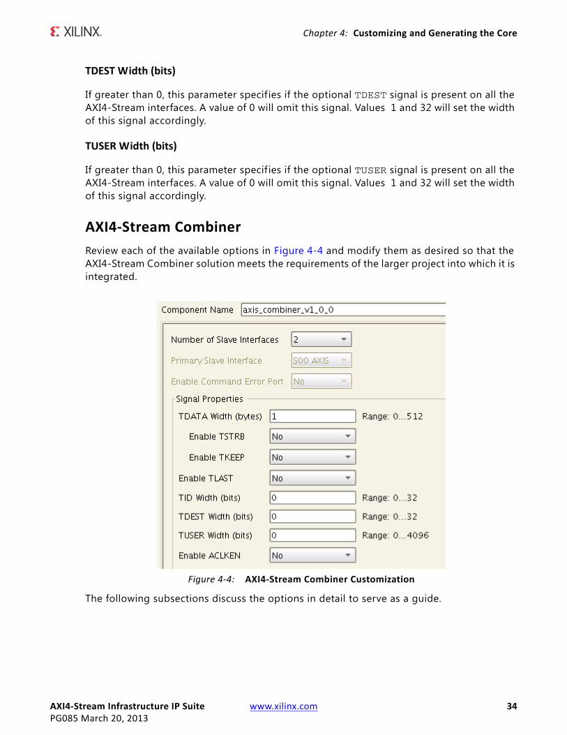
Review each of the available options in Figure 4-4 and modify them as desired so that the AXI4-Stream Combiner solution meets the requirements of the larger project into which it is integrated.
The following subsections discuss the options in detail to serve as a guide.
X-Ref Target - Figure 4-4
Figure 4‐4: AXI4‐Stream Combiner Customization
AXI4‐Stream Infrastructure IP Suite www.xilinx.com 35PG085 March 20, 2013
Chapter 4: Customizing and Generating the Core
Global Parameters
Component Name
The base name of the output f iles generated for the core. Names must begin with a letter and can be composed of any of the following characters: a to z, 0 to 9, and "_".
Number of Slave Interfaces
This parameter specifies the number of AXI4-Stream slave interfaces present on the IP. The value can be 2 and 16. The AXI4-Stream master interface signals TDATA, TSTRB, TKEEP, TUSER width are multiplied by this value.
Primary Slave Interface
This option specif ies the Slave Interface that is used to pass the TLAST, TID, and TDEST signals to the master interface.
Enable Command Port Error
If set to Yes, this option enables the s_cmd_err port if TID, TDEST, TLAST signals do not match the slave interface specified by the Primary Slave Interface option.
Signal Properties
TDATA Width (bytes)
This parameter specif ies the width in bytes of the TDATA signal on each of the AXI4-Stream slave interfaces. The AXI4-Stream master interface TDATA width will be this value multiplied by the Number of Slave Interfaces parameter. This parameter is an integer and can vary from 0 to (512/Number of Slave Interfaces). Set to 0 to omit the TDATA signal. If the TDATA signal is omitted, then the TKEEP and TSTRB signals are also omitted. The width of the port will be multiplied by 8 to get the width in bits.
Enable TSTRB
If set to Yes, this parameters specif ies if the optional TSTRB signal is present on all the AXI4-Stream interfaces. This option can only be enabled if the TDATA Width (bytes) parameter is greater than 0.
Enable TKEEP
If set to Yes, this parameters specif ies if the optional TKEEP signal is present on all the AXI4-Stream interfaces. This option can only be enabled if the TDATA Width (bytes) parameter is greater than 0.
AXI4‐Stream Infrastructure IP Suite www.xilinx.com 36PG085 March 20, 2013
Chapter 4: Customizing and Generating the Core
Enable TLAST
If set to Yes, this parameters specif ies if the optional TLAST signal is present on all the AXI4-Stream interfaces.
TID Width (bits)
If greater than 0, this parameter specifies if the optional TID signal is present on all the AXI4-Stream interfaces. A value of 0 will omit this signal. Values 1 and 32 will set the width of this signal accordingly.
TDEST Width (bits)
If greater than 0, this parameter specif ies if the optional TDEST signal is present on all the AXI4-Stream interfaces. A value of 0 will omit this signal. Values 1 and 32 will set the width of this signal accordingly.
TUSER Width (bits)
If greater than 0, this parameter specif ies if the optional TUSER signal is present on all the AXI4-Stream interfaces. A value of 0 will omit this signal. Values 1 and 32 will set the width of this signal accordingly on the AXI4-Stream slave interfaces. The AXI4-Stream master interface TUSER width will be to set to this value multiplied by Number of Slave Interfaces.
Enable ACLKEN
If set to Yes, this parameter specifies if the optional ACLKEN signal is present with all the AXI4-Stream interfaces clocks.
AXI4‐Stream Data FIFO
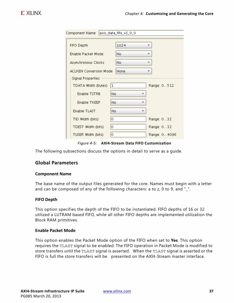
Review each of the available options in Figure 4-5 and modify them as desired so that the AXI4-Stream Data FIFO solution meets the requirements of the larger project into which it is integrated.
AXI4‐Stream Infrastructure IP Suite www.xilinx.com 37PG085 March 20, 2013
Chapter 4: Customizing and Generating the Core
The following subsections discuss the options in detail to serve as a guide.
Global Parameters
Component Name
The base name of the output f iles generated for the core. Names must begin with a letter and can be composed of any of the following characters: a to z, 0 to 9, and "_".
FIFO Depth
This option specif ies the depth of the FIFO to be instantiated. FIFO depths of 16 or 32 utilized a LUTRAM based FIFO, while all other FIFO depths are implemented utilization the Block RAM primitives.
Enable Packet Mode
This option enables the Packet Mode option of the FIFO when set to Yes. This option requires the TLAST signal to be enabled. The FIFO operation in Packet Mode is modif ied to store transfers until the TLAST signal is asserted. When the TLAST signal is asserted or the FIFO is full the store transfers will be presented on the AXI4-Stream master interface.
X-Ref Target - Figure 4-5
Figure 4‐5: AXI4‐Stream Data FIFO Customization
AXI4‐Stream Infrastructure IP Suite www.xilinx.com 38PG085 March 20, 2013
Chapter 4: Customizing and Generating the Core
Asynchronous clocks
If set to Yes, then the S_AXIS_ACLK and M_AXIS_ACLK clock signals are assumed to be asynchronous to each other and the IP operates in asynchronous mode.
ACLKEN Conversion Mode
This pull-down option selects the conversion mode for the ACLKEN signal. Extra latency and logic is incurred when ACLKEN conversion is performed. The options are:
• None - There are no ACLKEN signals associated with the IP.
• S AXIS Only - There is an S_AXIS_ACLKEN signal associated with the S_AXIS_ACLK clock signal and no M_AXIS_ACLKEN signal.
• M AXIS Only - There is an M_AXIS_ACLKEN signal associated with the M_AXIS_ACLK clock signal and no S_AXIS_ACLKEN signal.
• S AXIS & M AXIS - Both clocks have ACLKEN signals associated with them.
Signal Properties
TDATA Width (bytes)
This parameter specif ies the width in bytes of the TDATA signal on all the AXI4-Stream interfaces. This parameter is an integer and can vary from 0 to 512. Set to 0 to omit the TDATA signal. If the TDATA signal is omitted, then the TKEEP and TSTRB signals are also omitted. The width of the port will be multiplied by 8 to get the width in bits.
Enable TSTRB
If set to Yes, this parameters specif ies if the optional TSTRB signal is present on all the AXI4-Stream interfaces. This option can only be enabled if the TDATA Width (bytes) parameter is greater than 0.
Enable TKEEP
If set to Yes, this parameters specif ies if the optional TKEEP signal is present on all the AXI4-Stream interfaces. This option can only be enabled if the TDATA Width (bytes) parameter is greater than 0.
Enable TLAST
If set to Yes, this parameters specif ies if the optional TLAST signal is present on all the AXI4-Stream interfaces.
AXI4‐Stream Infrastructure IP Suite www.xilinx.com 39PG085 March 20, 2013
Chapter 4: Customizing and Generating the Core
TID Width (bits)
If greater than 0, this parameter specifies if the optional TID signal is present on all the AXI4-Stream interfaces. A value of 0 will omit this signal. Values 1 and 32 will set the width of this signal accordingly.
TDEST Width (bits)
If greater than 0, this parameter specif ies if the optional TDEST signal is present on all the AXI4-Stream interfaces. A value of 0 will omit this signal. Values 1 and 32 will set the width of this signal accordingly.
TUSER Width (bits)
If greater than 0, this parameter specif ies if the optional TUSER signal is present on all the AXI4-Stream interfaces. A value of 0 will omit this signal. Values 1 and 32 will set the width of this signal accordingly.
AXI4‐Stream Data Width Converter
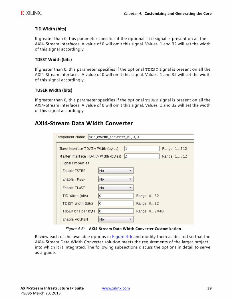
Review each of the available options in Figure 4-6 and modify them as desired so that the AXI4-Stream Data Width Converter solution meets the requirements of the larger project into which it is integrated. The following subsections discuss the options in detail to serve as a guide.
X-Ref Target - Figure 4-6
Figure 4‐6: AXI4‐Stream Data Width Converter Customization
AXI4‐Stream Infrastructure IP Suite www.xilinx.com 40PG085 March 20, 2013
Chapter 4: Customizing and Generating the Core
Global Parameters
Component Name
The base name of the output f iles generated for the core. Names must begin with a letter and can be composed of any of the following characters: a to z, 0 to 9, and "_".
Slave Interface TDATA Width (bytes)
This parameter specif ies the width in bytes of the TDATA signal on the AXI4-Stream slave interface. This parameter is an integer and can vary from 1 to 512. The width of the port will be multiplied by 8 to get the width in bits. This value cannot be the same as the value of Master Interface TDATA Width (bytes).
Master Interface TDATA Width (bytes)
This parameter specif ies the width in bytes of the TDATA signal on the AXI4-Stream master interface. This parameter is an integer and can vary from 1 to 512. The width of the port will be multiplied by 8 to get the width in bits. This value cannot be the same as the value of Slave Interface TDATA Width (bytes).
Signal Properties
Enable TSTRB
If set to Yes, this parameters specif ies if the optional TSTRB signal is present on all the AXI4-Stream interfaces.
Enable TKEEP
If set to Yes, this parameters specif ies if the optional TKEEP signal is present on all the AXI4-Stream interfaces. Certain configurations may introduce null-bytes into the system. In these situations, the m_axis_tkeep signal is always present regardless of the value of this parameter.
Enable TLAST
If set to Yes, this parameters specif ies if the optional TLAST signal is present on all the AXI4-Stream interfaces.
TID Width (bits)
If greater than 0, this parameter specifies if the optional TID signal is present on all the AXI4-Stream interfaces. A value of 0 will omit this signal. Values 1 and 32 will set the width of this signal accordingly.
AXI4‐Stream Infrastructure IP Suite www.xilinx.com 41PG085 March 20, 2013
Chapter 4: Customizing and Generating the Core
TDEST Width (bits)
If greater than 0, this parameter specif ies if the optional TDEST signal is present on all the AXI4-Stream interfaces. A value of 0 will omit this signal. Values 1 and 32 will set the width of this signal accordingly.
TUSER Width (bits)
If greater than 0, this parameter specif ies if the optional TUSER signal is present on all the AXI4-Stream interfaces. A value of 0 will omit this signal. Values 1 and 32 will set the width of this signal accordingly.
Enable ACLKEN
If set to Yes, this parameter specifies if the optional ACLKEN signal is present with all the AXI4-Stream interfaces clocks.
AXI4‐Stream Register Slice
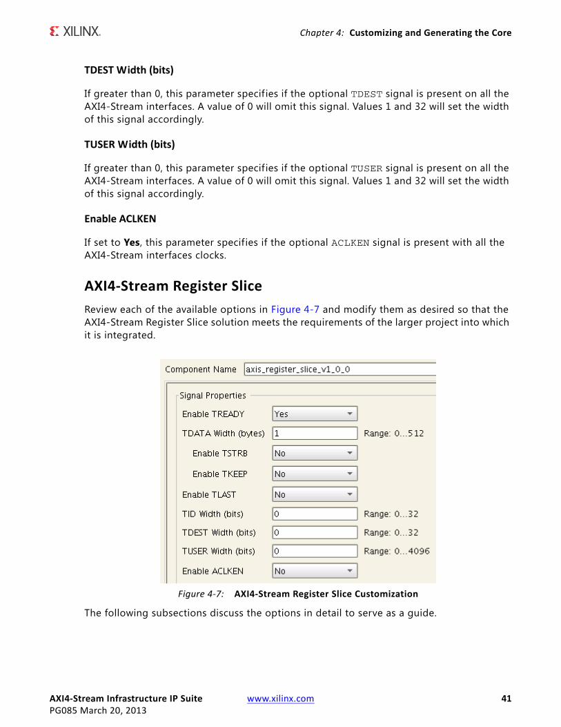
Review each of the available options in Figure 4-7 and modify them as desired so that the AXI4-Stream Register Slice solution meets the requirements of the larger project into which it is integrated.
The following subsections discuss the options in detail to serve as a guide.
X-Ref Target - Figure 4-7
Figure 4‐7: AXI4‐Stream Register Slice Customization
AXI4‐Stream Infrastructure IP Suite www.xilinx.com 42PG085 March 20, 2013
Chapter 4: Customizing and Generating the Core
Global Parameters
Component Name
The base name of the output f iles generated for the core. Names must begin with a letter and can be composed of any of the following characters: a to z, 0 to 9, and "_".
Signal Properties
Enable TREADY
If set to Yes, this parameters specif ies if the optional TREADY signal is present on all the AXI4-Stream interfaces. Set to No to omit the signal.
TIP: The AXI4-Stream specification recommends that TREADY is always included.
TDATA Width (bytes)
This parameter specif ies the width in bytes of the TDATA signal on all the AXI4-Stream interfaces. This parameter is an integer and can vary from 0 to 512. Set to 0 to omit the TDATA signal. If the TDATA signal is omitted, then the TKEEP and TSTRB signals are also omitted. The width of the port will be multiplied by 8 to get the width in bits.
Enable TSTRB
If set to Yes, this parameters specif ies if the optional TSTRB signal is present on all the AXI4-Stream interfaces. This option can only be enabled if the TDATA Width (bytes) parameter is greater than 0.
Enable TKEEP
If set to Yes, this parameters specif ies if the optional TKEEP signal is present on all the AXI4-Stream interfaces. This option can only be enabled if the TDATA Width (bytes) parameter is greater than 0.
Enable TLAST
If set to Yes, this parameters specif ies if the optional TLAST signal is present on all the AXI4-Stream interfaces.
TID Width (bits)
If greater than 0, this parameter specifies if the optional TID signal is present on all the AXI4-Stream interfaces. A value of 0 will omit this signal. Values 1 and 32 will set the width of this signal accordingly.
AXI4‐Stream Infrastructure IP Suite www.xilinx.com 43PG085 March 20, 2013
Chapter 4: Customizing and Generating the Core
TDEST Width (bits)
If greater than 0, this parameter specif ies if the optional TDEST signal is present on all the AXI4-Stream interfaces. A value of 0 will omit this signal. Values 1 and 32 will set the width of this signal accordingly.
TUSER Width (bits)
If greater than 0, this parameter specif ies if the optional TUSER signal is present on all the AXI4-Stream interfaces. A value of 0 will omit this signal. Values 1 and 32 will set the width of this signal accordingly.
Enable ACLKEN
If set to Yes, this parameter specifies if the optional ACLKEN signal is present with all the AXI4-Stream interfaces clocks.
AXI4‐Stream Subset Converter
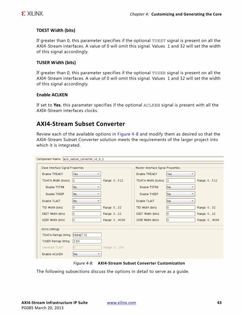
Review each of the available options in Figure 4-8 and modify them as desired so that the AXI4-Stream Subset Converter solution meets the requirements of the larger project into which it is integrated.
The following subsections discuss the options in detail to serve as a guide.
X-Ref Target - Figure 4-8
Figure 4‐8: AXI4‐Stream Subset Converter Customization
AXI4‐Stream Infrastructure IP Suite www.xilinx.com 44PG085 March 20, 2013
Chapter 4: Customizing and Generating the Core
Global Parameters
Component Name
The base name of the output f iles generated for the core. Names must begin with a letter and can be composed of any of the following characters: a to z, 0 to 9, and "_".
Slave Interface Signal Properties
Enable TREADY
If set to Yes, this parameters specif ies if the optional TREADY signal is present on the AXI4-Stream slave interface. Set to No to omit the signal.
TIP: The AXI4-Stream specification recommends that TREADY is always included.
TDATA Width (bytes)
This parameter specif ies the width in bytes of the TDATA signal on the AXI4-Stream slave interface. This parameter is an integer and can vary from 0 to 512. Set to 0 to omit the TDATA signal. If the TDATA signal is omitted, then the TKEEP and TSTRB signals are also omitted. The width of the port will be multiplied by 8 to get the width in bits.
Enable TSTRB
If set to Yes, this parameters specif ies if the optional TSTRB signal is present on the AXI4-Stream slave interface. This option can only be enabled if the TDATA Width (bytes) parameter is greater than 0.
Enable TKEEP
If set to Yes, this parameters specif ies if the optional TKEEP signal is present on the AXI4-Stream slave interface. This option can only be enabled if the TDATA Width (bytes) parameter is greater than 0.
Enable TLAST
If set to Yes, this parameters specif ies if the optional TLAST signal is present on the AXI4-Stream slave interface.
TID Width (bits)
If greater than 0, this parameter specifies if the optional TID signal is present on the AXI4-Stream slave interface. A value of 0 will omit this signal. Values 1 and 32 will set the width of this signal accordingly.
AXI4‐Stream Infrastructure IP Suite www.xilinx.com 45PG085 March 20, 2013
Chapter 4: Customizing and Generating the Core
TDEST Width (bits)
If greater than 0, this parameter specifies if the optional TDEST signal is present on the AXI4-Stream slave interface. A value of 0 will omit this signal. Values 1 and 32 will set the width of this signal accordingly.
TUSER Width (bits)
If greater than 0, this parameter specifies if the optional TUSER signal is present on the AXI4-Stream slave interface. A value of 0 will omit this signal. Values 1 and 32 will set the width of this signal accordingly.
Master Interface Signal Properties
Enable TREADY
If set to Yes, this parameters specif ies if the optional TREADY signal is present on the AXI4-Stream slave interface. Set to No to omit the signal.
TIP: The AXI4-Stream specification recommends that TREADY is always included.
TDATA Width (bytes)
This parameter specif ies the width in bytes of the TDATA signal on the AXI4-Stream slave interface. This parameter is an integer and can vary from 0 to 512. Set to 0 to omit the TDATA signal. If the TDATA signal is omitted, then the TKEEP and TSTRB signals are also omitted. The width of the port will be multiplied by 8 to get the width in bits.
Enable TSTRB
If set to Yes, this parameters specif ies if the optional TSTRB signal is present on the AXI4-Stream slave interface. This option can only be enabled if the TDATA Width (bytes) parameter is greater than 0.
Enable TKEEP
If set to Yes, this parameters specif ies if the optional TKEEP signal is present on the AXI4-Stream slave interface. This option can only be enabled if the TDATA Width (bytes) parameter is greater than 0.
Enable TLAST
If set to Yes, this parameters specif ies if the optional TLAST signal is present on the AXI4-Stream slave interface.
AXI4‐Stream Infrastructure IP Suite www.xilinx.com 46PG085 March 20, 2013
Chapter 4: Customizing and Generating the Core
TID Width (bits)
If greater than 0, this parameter specifies if the optional TID signal is present on the AXI4-Stream slave interface. A value of 0 will omit this signal. Values 1 and 32 will set the width of this signal accordingly.
TDEST Width (bits)
If greater than 0, this parameter specifies if the optional TDEST signal is present on the AXI4-Stream slave interface. A value of 0 will omit this signal. Values 1 and 32 will set the width of this signal accordingly.
TUSER Width (bits)
If greater than 0, this parameter specifies if the optional TUSER signal is present on the AXI4-Stream slave interface. A value of 0 will omit this signal. Values 1 and 32 will set the width of this signal accordingly.
Extra Settings
TDATA Remap String/TUSER Remap String
The TDATA/TUSER Remap strings are used to remap input to output bytes/bits of the TDATA/TUSER signals, respectively.
The format of the remap user parameter follows syntax similar to Verilog vector concatenation.
• The remap parameter is a comma separated list of elements.
• Each element is either a constant or a bit slice of the SI signal.
° For example, if SI and MI TDATA width have the same value 32, the remap string tdata[31:0] will pass the entire TDATA signal from SI to MI unmodified.
° If the MI TDATA signal were 24 bits and the SI TDATA signal were 16 bits, a remap string of 8b00000000,tdata[15:0] will assign a constant 0 to the upper 8 bits of the MI signal and pass the SI TDATA through on the lower 16 bits.
• A bit-slice element can reference a single bit of the SI signal (eg, TDATA[0]) or a vector slice of the SI signal (eg, tdata[11:8]).
° The index values must not exceed the indices of the SI signal.
• The same SI bit can be mapped multiple times into the MI output.
° For example, tdata[7:0], tdata[7:0] repeats the SI TDATA least signif icant byte twice on MI signal.
• The combined width of the constants and the SI bit slices in the remap parameter must match the MI signal width.
AXI4‐Stream Infrastructure IP Suite www.xilinx.com 47PG085 March 20, 2013
Chapter 4: Customizing and Generating the Core
• The right-most element defines the least signif icant bits of the MI signal and the left-most element defines the most signif icant bits of the MI signal.
• The remap string can only reference bits of the corresponding SI signal.
° For example, the remap string for TDATA can only reference bits from the TDATA SI signal.
° It is not supported to reference a bit slice of another signal (eg, slicing TUSER signal into TDATA signal or vice versa).
• Constant elements and bit-slice elements can be freely mixed in the comma separated list of elements.
° For example, tdata[7:0],8b00000000,tdata[15:8] is a valid expression.
• Only binary format constant elements are supported.
° h format is not supported.
• The constant element must specify the number of bits that follow b and the number of bits that follow b must match the number of bits specif ied. If not, a validation error is given.
• If the SI signal width is 0, the remap string must be a constant element.
• If the MI signal width is 0, the remap string is 1b0.
• Bit slices are only valid when the SI signal width is greater than 0.
• Remapping of other signals (eg TKEEP, TSTRB, etc) is not currently supported.
Generate TLAST
This parameter can be set if the TLAST signal is enabled on the master interface, but not on the slave interface. The number specif ies how many transfers to count before asserting the TLAST signal. A value of 0 indicates that the TLAST signal should always be de-asserted. Conversely, a value of 1 indicates that the TLAST signal should be asserted on every transfer. A value of 2 indicates that the TLAST signal should be asserted on every other transfer and so on. Values 0 and 256 are accepted.
Enable ACLKEN
If set to Yes, this parameter specifies if the optional ACLKEN signal is present with all the AXI4-Stream interfaces clocks.
AXI4‐Stream Switch
Review each of the available options in Figure 4-9 and modify them as desired so that the AXI4-Stream Switch solution meets the requirements of the larger project into which it is integrated.
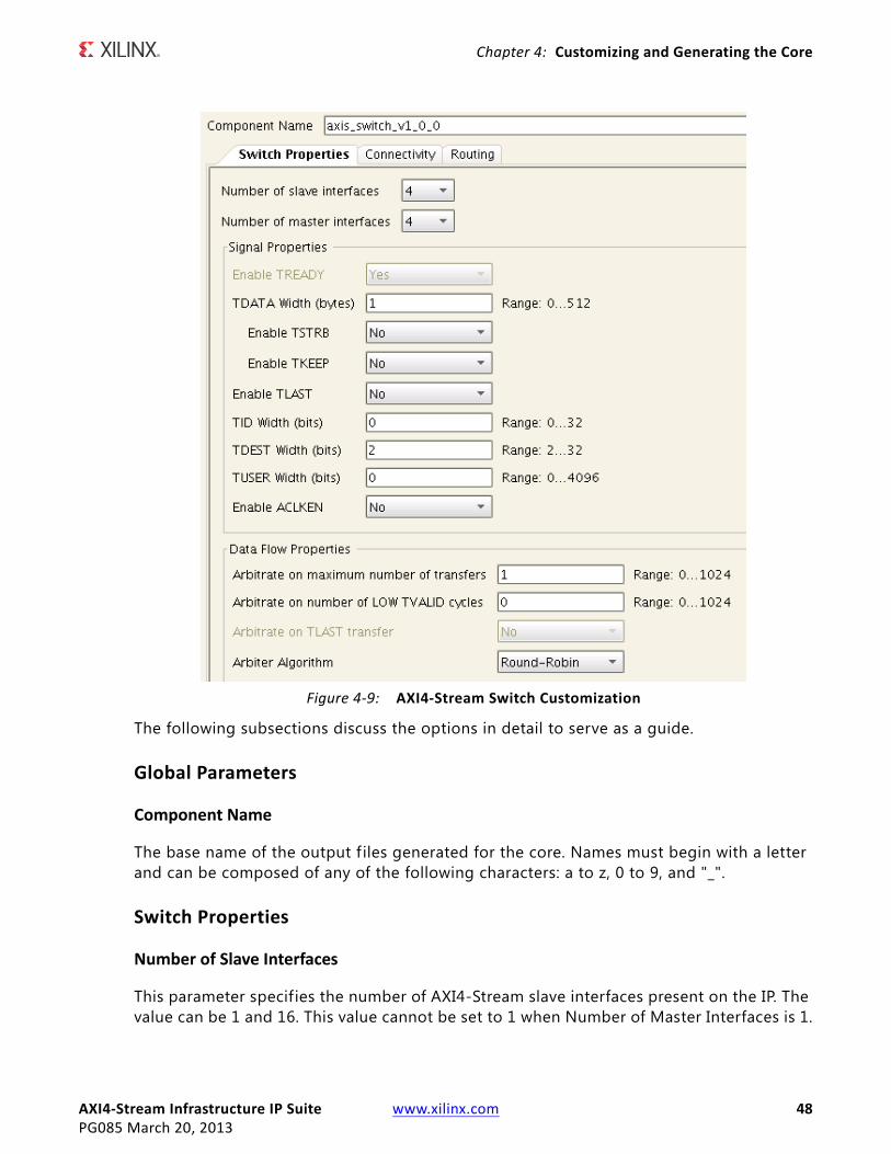
AXI4‐Stream Infrastructure IP Suite www.xilinx.com 48PG085 March 20, 2013
Chapter 4: Customizing and Generating the Core
The following subsections discuss the options in detail to serve as a guide.
Global Parameters
Component Name
The base name of the output f iles generated for the core. Names must begin with a letter and can be composed of any of the following characters: a to z, 0 to 9, and "_".
Switch Properties
Number of Slave Interfaces
This parameter specifies the number of AXI4-Stream slave interfaces present on the IP. The value can be 1 and 16. This value cannot be set to 1 when Number of Master Interfaces is 1.
X-Ref Target - Figure 4-9
Figure 4‐9: AXI4‐Stream Switch Customization
AXI4‐Stream Infrastructure IP Suite www.xilinx.com 49PG085 March 20, 2013
Chapter 4: Customizing and Generating the Core
Number of Master Interfaces
This parameter specif ies the number of AXI4-Stream master interfaces present on the IP. The value can be 1 and 16. This value cannot be set to 1 when Number of Slave Interfaces is 1.
Signal Properties
Enable TREADY
If set to Yes, this parameters specif ies if the optional TREADY signal is present on all the AXI4-Stream interfaces. Set to No to omit the signal.
TIP: The AXI4-Stream specification recommends that TREADY is always included.
This option can only be set to No when the Number of Slave Interfaces is 1.
TDATA Width (bytes)
This parameter specif ies the width in bytes of the TDATA signal on all the AXI4-Stream interfaces. This parameter is an integer and can vary from 0 to 512. Set to 0 to omit the TDATA signal. If the TDATA signal is omitted, then the TKEEP and TSTRB signals are also omitted. The width of the port will be multiplied by 8 to get the width in bits.
Enable TSTRB
If set to Yes, this parameters specif ies if the optional TSTRB signal is present on all the AXI4-Stream interfaces. This option can only be enabled if the TDATA Width (bytes) parameter is greater than 0.
Enable TKEEP
If set to Yes, this parameters specif ies if the optional TKEEP signal is present on all the AXI4-Stream interfaces. This option can only be enabled if the TDATA Width (bytes) parameter is greater than 0.
Enable TLAST
If set to Yes, this parameters specif ies if the optional TLAST signal is present on all the AXI4-Stream interfaces.
TID Width (bits)
If greater than 0, this parameter specifies if the optional TID signal is present on all the AXI4-Stream interfaces. A value of 0 will omit this signal. Values 1 and 32 will set the width of this signal accordingly.
AXI4‐Stream Infrastructure IP Suite www.xilinx.com 50PG085 March 20, 2013
Chapter 4: Customizing and Generating the Core
TDEST Width (bits)
If greater than 0, this parameter specif ies if the optional TDEST signal is present on all the AXI4-Stream interfaces. A value of 0 will omit this signal. Values 1 and 32 will set the width of this signal accordingly.
TUSER Width (bits)
If greater than 0, this parameter specif ies if the optional TUSER signal is present on all the AXI4-Stream interfaces. A value of 0 will omit this signal. Values 1 and 32 will set the width of this signal accordingly.
Enable ACLKEN
If set to Yes, this parameter specifies if the optional ACLKEN signal is present with all the AXI4-Stream interfaces clocks.
Data Flow Properties
Data Flow Properties options are available to modify only if the Number of Slave Interfaces is greater than 1.
Arbitrate on Maximum Number of Transfers
This setting specifies how many transfers to count before relinquishing the granted arbitration. If set to zero, then the number is infinite and Arbitrate on TLAST transfer must be set. If set to one, then after each transfer, the interconnect switch relinquishes control and requests another arbitration. If set to a value greater than one, then after the specif ied number of transfers, the arbitration is relinquished. For example, setting this value to 16 allows 16 transfers to pass from slave interface to master interface per each arbitration grant.
Arbitrate on Number of LOW TVALID Cycles
This setting allows relinquishing of a granted arbitration without a transfer. A watchdog timer is instantiated and counts the number of consecutive LOW TVALID signals the granted SI and MI interfaces. When the requisite number of LOW TVALID cycles is counted as specified here, the switch relinquishes the granted arbitration and signals that the transaction is complete to the arbiter. If this setting is set to 0, no watchdog timer is instantiated. If there is more than one slave interface, more than one master interface, and the Arbitrate on maximum number of transfers setting is greater than 1, this setting cannot be set to zero. This ensures that deadlock cannot occur.
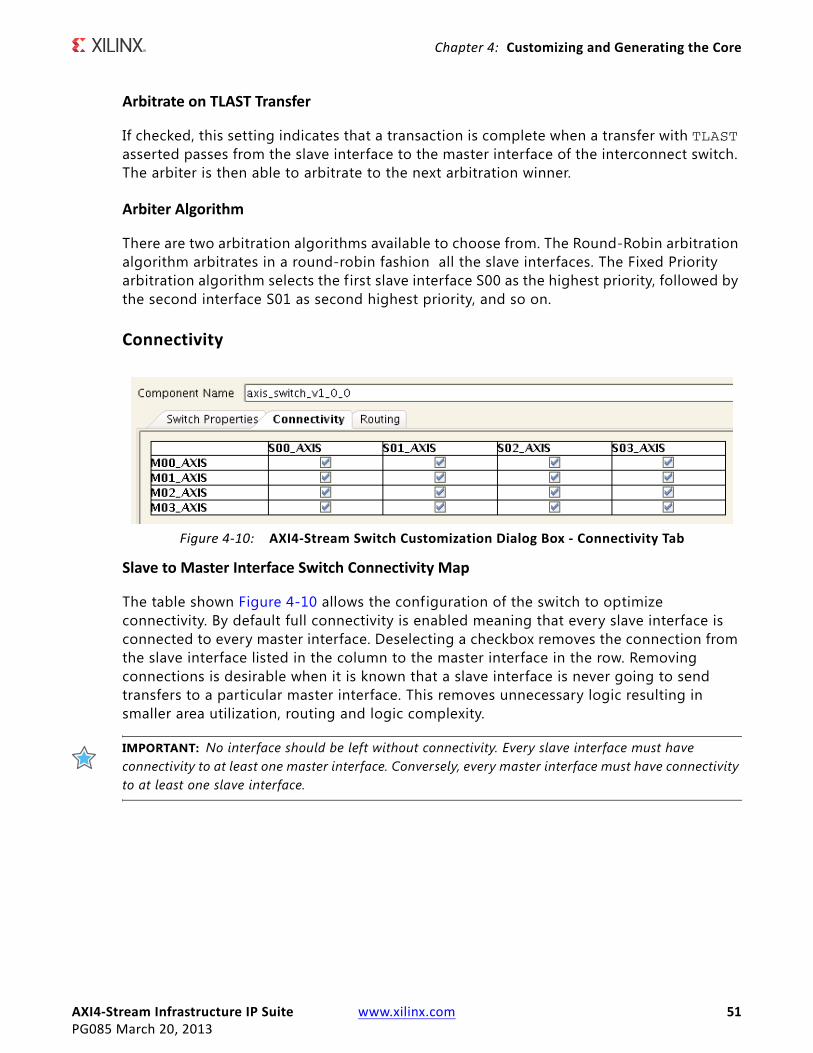
AXI4‐Stream Infrastructure IP Suite www.xilinx.com 51PG085 March 20, 2013
Chapter 4: Customizing and Generating the Core
Arbitrate on TLAST Transfer
If checked, this setting indicates that a transaction is complete when a transfer with TLAST asserted passes from the slave interface to the master interface of the interconnect switch. The arbiter is then able to arbitrate to the next arbitration winner.
Arbiter Algorithm
There are two arbitration algorithms available to choose from. The Round-Robin arbitration algorithm arbitrates in a round-robin fashion all the slave interfaces. The Fixed Priority arbitration algorithm selects the f irst slave interface S00 as the highest priority, followed by the second interface S01 as second highest priority, and so on.
Connectivity
Slave to Master Interface Switch Connectivity Map
The table shown Figure 4-10 allows the configuration of the switch to optimize connectivity. By default full connectivity is enabled meaning that every slave interface is connected to every master interface. Deselecting a checkbox removes the connection from the slave interface listed in the column to the master interface in the row. Removing connections is desirable when it is known that a slave interface is never going to send transfers to a particular master interface. This removes unnecessary logic resulting in smaller area utilization, routing and logic complexity.
IMPORTANT: No interface should be left without connectivity. Every slave interface must have connectivity to at least one master interface. Conversely, every master interface must have connectivity to at least one slave interface.
X-Ref Target - Figure 4-10
Figure 4‐10: AXI4‐Stream Switch Customization Dialog Box ‐ Connectivity Tab
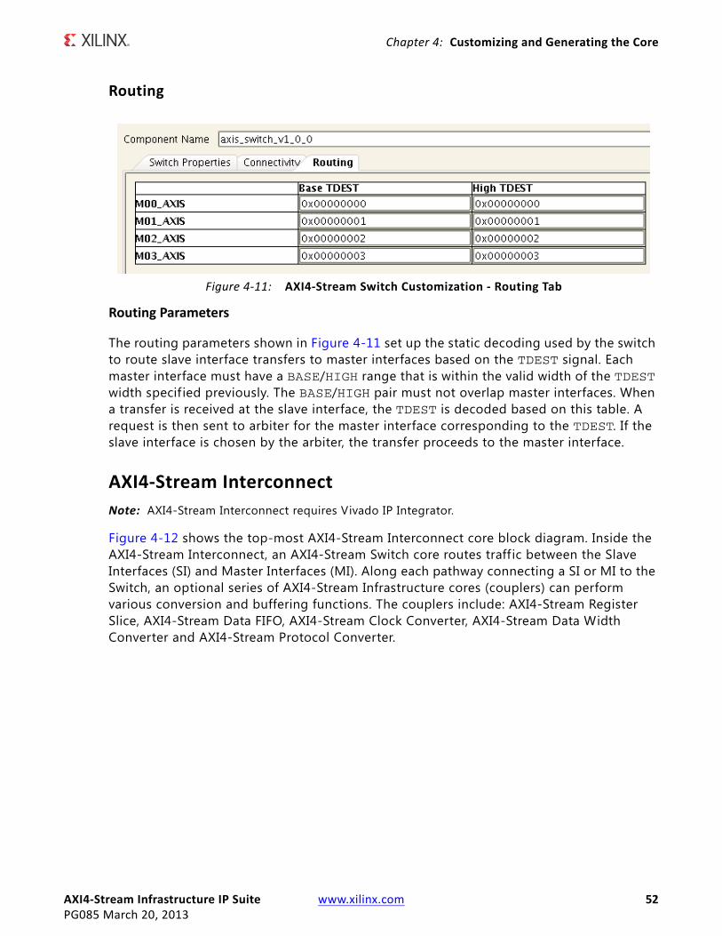
AXI4‐Stream Infrastructure IP Suite www.xilinx.com 52PG085 March 20, 2013
Chapter 4: Customizing and Generating the Core
Routing
Routing Parameters
The routing parameters shown in Figure 4-11 set up the static decoding used by the switch to route slave interface transfers to master interfaces based on the TDEST signal. Each master interface must have a BASE/HIGH range that is within the valid width of the TDEST width specif ied previously. The BASE/HIGH pair must not overlap master interfaces. When a transfer is received at the slave interface, the TDEST is decoded based on this table. A request is then sent to arbiter for the master interface corresponding to the TDEST. If the slave interface is chosen by the arbiter, the transfer proceeds to the master interface.
AXI4‐Stream Interconnect
Note: AXI4-Stream Interconnect requires Vivado IP Integrator.
Figure 4-12 shows the top-most AXI4-Stream Interconnect core block diagram. Inside the AXI4-Stream Interconnect, an AXI4-Stream Switch core routes traffic between the Slave Interfaces (SI) and Master Interfaces (MI). Along each pathway connecting a SI or MI to the Switch, an optional series of AXI4-Stream Infrastructure cores (couplers) can perform various conversion and buffering functions. The couplers include: AXI4-Stream Register Slice, AXI4-Stream Data FIFO, AXI4-Stream Clock Converter, AXI4-Stream Data Width Converter and AXI4-Stream Protocol Converter.
X-Ref Target - Figure 4-11
Figure 4‐11: AXI4‐Stream Switch Customization ‐ Routing Tab
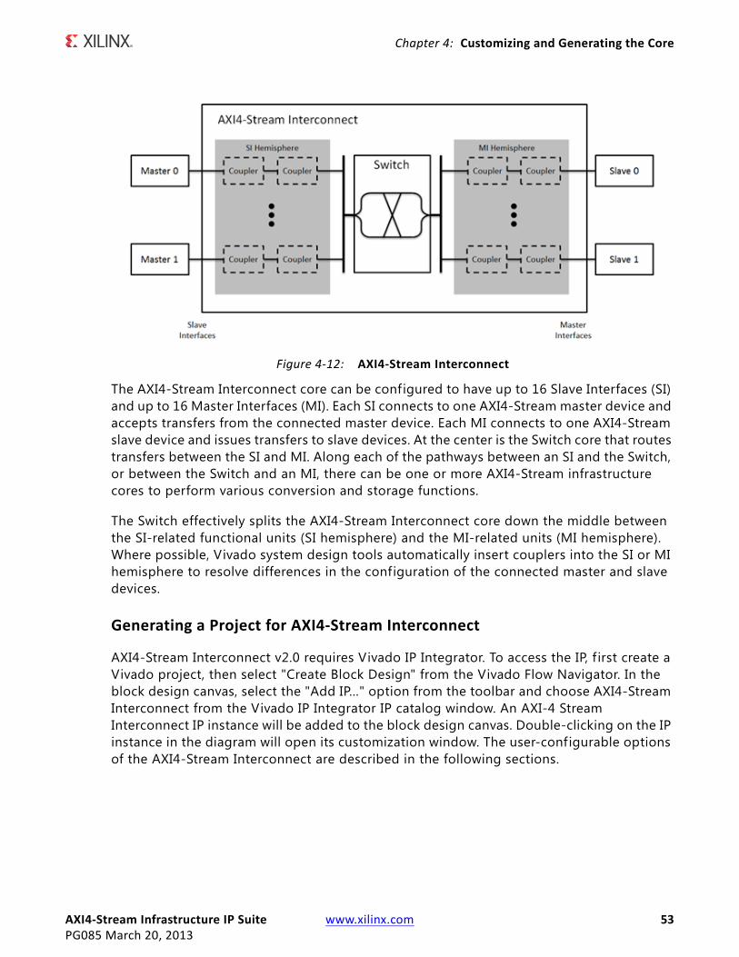
AXI4‐Stream Infrastructure IP Suite www.xilinx.com 53PG085 March 20, 2013
Chapter 4: Customizing and Generating the Core
The AXI4-Stream Interconnect core can be configured to have up to 16 Slave Interfaces (SI) and up to 16 Master Interfaces (MI). Each SI connects to one AXI4-Stream master device and accepts transfers from the connected master device. Each MI connects to one AXI4-Stream slave device and issues transfers to slave devices. At the center is the Switch core that routes transfers between the SI and MI. Along each of the pathways between an SI and the Switch, or between the Switch and an MI, there can be one or more AXI4-Stream infrastructure cores to perform various conversion and storage functions.
The Switch effectively splits the AXI4-Stream Interconnect core down the middle between the SI-related functional units (SI hemisphere) and the MI-related units (MI hemisphere). Where possible, Vivado system design tools automatically insert couplers into the SI or MI hemisphere to resolve differences in the configuration of the connected master and slave devices.
Generating a Project for AXI4‐Stream Interconnect
AXI4-Stream Interconnect v2.0 requires Vivado IP Integrator. To access the IP, f irst create a Vivado project, then select "Create Block Design" from the Vivado Flow Navigator. In the block design canvas, select the "Add IP…" option from the toolbar and choose AXI4-Stream Interconnect from the Vivado IP Integrator IP catalog window. An AXI-4 Stream Interconnect IP instance will be added to the block design canvas. Double-clicking on the IP instance in the diagram will open its customization window. The user-configurable options of the AXI4-Stream Interconnect are described in the following sections.
X-Ref Target - Figure 4-12
Figure 4‐12: AXI4‐Stream Interconnect
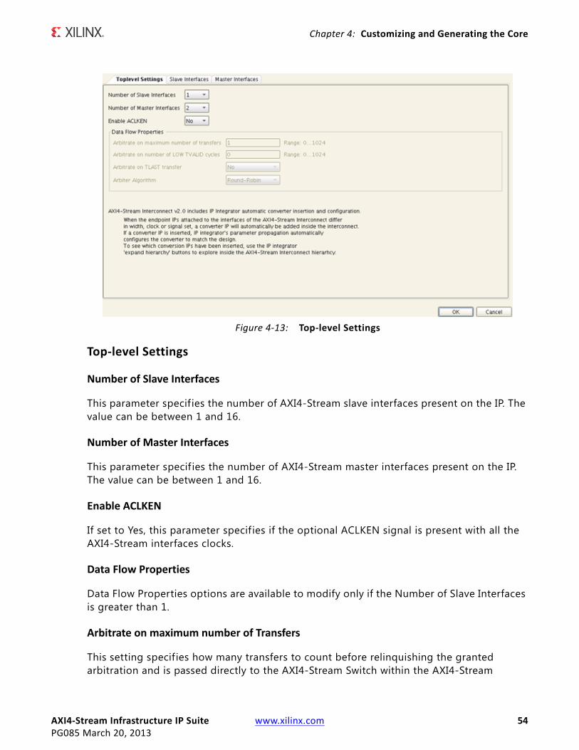
AXI4‐Stream Infrastructure IP Suite www.xilinx.com 54PG085 March 20, 2013
Chapter 4: Customizing and Generating the Core
Top‐level Settings
Number of Slave Interfaces
This parameter specifies the number of AXI4-Stream slave interfaces present on the IP. The value can be between 1 and 16.
Number of Master Interfaces
This parameter specif ies the number of AXI4-Stream master interfaces present on the IP. The value can be between 1 and 16.
Enable ACLKEN
If set to Yes, this parameter specif ies if the optional ACLKEN signal is present with all the AXI4-Stream interfaces clocks.
Data Flow Properties
Data Flow Properties options are available to modify only if the Number of Slave Interfaces is greater than 1.
Arbitrate on maximum number of Transfers
This setting specifies how many transfers to count before relinquishing the granted arbitration and is passed directly to the AXI4-Stream Switch within the AXI4-Stream
X-Ref Target - Figure 4-13
Figure 4‐13: Top‐level Settings
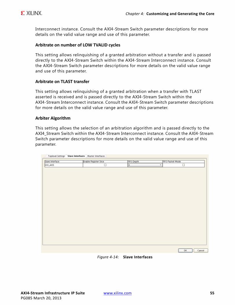
AXI4‐Stream Infrastructure IP Suite www.xilinx.com 55PG085 March 20, 2013
Chapter 4: Customizing and Generating the Core
Interconnect instance. Consult the AXI4-Stream Switch parameter descriptions for more details on the valid value range and use of this parameter.
Arbitrate on number of LOW TVALID cycles
This setting allows relinquishing of a granted arbitration without a transfer and is passed directly to the AXI4-Stream Switch within the AXI4-Stream Interconnect instance. Consult the AXI4-Stream Switch parameter descriptions for more details on the valid value range and use of this parameter.
Arbitrate on TLAST transfer
This setting allows relinquishing of a granted arbitration when a transfer with TLAST asserted is received and is passed directly to the AXI4-Stream Switch within the AXI4-Stream Interconnect instance. Consult the AXI4-Stream Switch parameter descriptions for more details on the valid value range and use of this parameter.
Arbiter Algorithm
This setting allows the selection of an arbitration algorithm and is passed directly to the AXI4_Stream Switch within the AXI4-Stream Interconnect instance. Consult the AXI4-Stream Switch parameter descriptions for more details on the valid value range and use of this parameter.
X-Ref Target - Figure 4-14
Figure 4‐14: Slave Interfaces
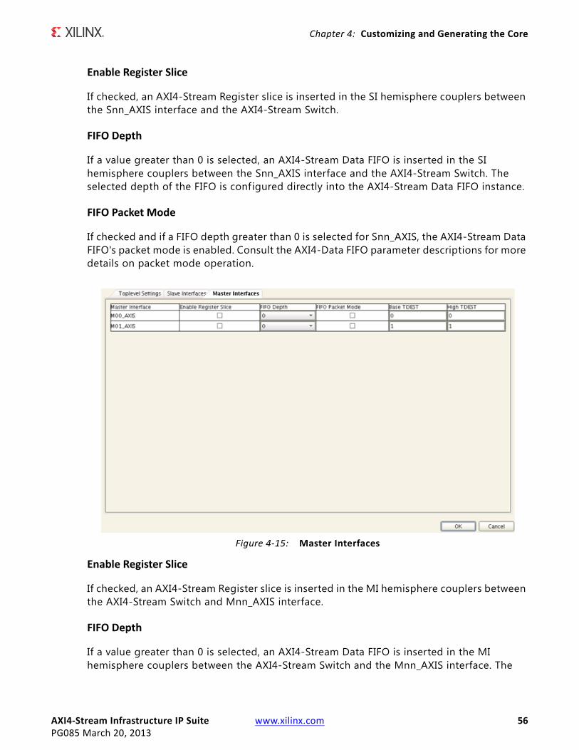
AXI4‐Stream Infrastructure IP Suite www.xilinx.com 56PG085 March 20, 2013
Chapter 4: Customizing and Generating the Core
Enable Register Slice
If checked, an AXI4-Stream Register slice is inserted in the SI hemisphere couplers between the Snn_AXIS interface and the AXI4-Stream Switch.
FIFO Depth
If a value greater than 0 is selected, an AXI4-Stream Data FIFO is inserted in the SI hemisphere couplers between the Snn_AXIS interface and the AXI4-Stream Switch. The selected depth of the FIFO is configured directly into the AXI4-Stream Data FIFO instance.
FIFO Packet Mode
If checked and if a FIFO depth greater than 0 is selected for Snn_AXIS, the AXI4-Stream Data FIFO's packet mode is enabled. Consult the AXI4-Data FIFO parameter descriptions for more details on packet mode operation.
Enable Register Slice
If checked, an AXI4-Stream Register slice is inserted in the MI hemisphere couplers between the AXI4-Stream Switch and Mnn_AXIS interface.
FIFO Depth
If a value greater than 0 is selected, an AXI4-Stream Data FIFO is inserted in the MI hemisphere couplers between the AXI4-Stream Switch and the Mnn_AXIS interface. The
X-Ref Target - Figure 4-15
Figure 4‐15: Master Interfaces
AXI4‐Stream Infrastructure IP Suite www.xilinx.com 57PG085 March 20, 2013
Chapter 4: Customizing and Generating the Core
selected depth of the FIFO is configured directly into the AXI4-Stream Data FIFO instance. Consult the AXI4-Stream Data FIFO parameter descriptions for more details on the valid range of FIFO depth.
FIFO Packet Mode
If checked and if a FIFO depth greater than 0 is selected for Snn_AXIS, the AXI4-Stream Data FIFO's packet mode is enabled. Consult the AXI4-Stream Data FIFO parameter descriptions for more details on packet mode operation.
Base TDEST and High TDEST
The routing parameters shown in Figure 4-15 set up the static decoding to route slave interface transfers to master interfaces based on the TDEST signal and are passed directly to the AXI4-Stream Switch instance within the AXI4-Stream Interconnect. Consult the AXI4-Stream Switch parameter descriptions for more details on the valid range and use of routing parameters.
Output GenerationEach of the AXI4-Stream Infrastructure IP suite deliverables are organized in the directory <project name>/<project name>.srcs/sources_1/ip/<component name> and is designated as the <ip source dir>. The relevant contents of the directories are described in the following sections.
Vivado Design Tools Project Files
The Vivado design tools project f iles are located in the root of the <ip source dir>.
Table 4‐1: Project Files
Name Description
<component_name>.xciVivado tools IP configuration options f ile. This f ile can be imported into any Vivado tools design and be used to generate all other IP source files.
<component_name>.xdc AXI4-Stream Infrastructure IP Xilinx design constraints.
<component_name>.{veo|vho} AXI4-Stream Infrastructure IP instantiation template.
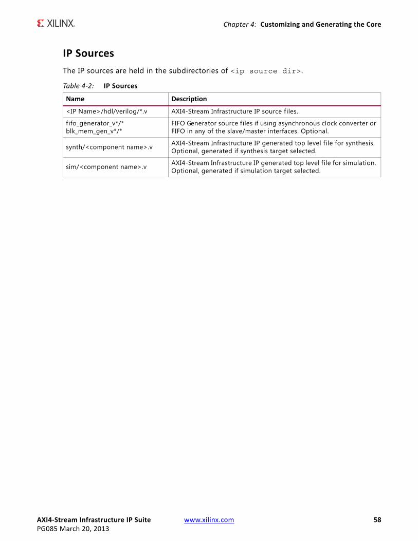
AXI4‐Stream Infrastructure IP Suite www.xilinx.com 58PG085 March 20, 2013
Chapter 4: Customizing and Generating the Core
IP Sources
The IP sources are held in the subdirectories of <ip source dir>.
Table 4‐2: IP Sources
Name Description
<IP Name>/hdl/verilog/*.v AXI4-Stream Infrastructure IP source f iles.
f ifo_generator_v*/*blk_mem_gen_v*/*
FIFO Generator source f iles if using asynchronous clock converter or FIFO in any of the slave/master interfaces. Optional.
synth/<component name>.v AXI4-Stream Infrastructure IP generated top level f ile for synthesis. Optional, generated if synthesis target selected.
sim/<component name>.v AXI4-Stream Infrastructure IP generated top level f ile for simulation. Optional, generated if simulation target selected.

AXI4‐Stream Infrastructure IP Suite www.xilinx.com 59PG085 March 20, 2013
Chapter 5
Constraining the CoreThis chapter contains information about constraining the core in the Vivado™ Design Suite environment.
The AXI4-Stream Infrastructure IP does not generally require any additional timing constraints other than clock period constraints on its clocks inputs. When an asynchronous clock converter is utilized, the underlying FIFO Generator asynchronous FIFO is instantiated and the IP generates a core level constraint f ile to prevent timing paths crossing clock domains from causing false timing errors. Those constraints apply only to internal logic inside the AXI4-Stream Infrastructure IP and are automatically generated with the IP.
AXI4‐Stream Infrastructure IP Suite www.xilinx.com 60PG085 March 20, 2013
Appendix A
DebuggingThis appendix includes details about resources available on the Xilinx Support website and debugging tools. In addition, this appendix provides a step-by-step debugging process and a flow diagram to guide you through debugging the AXI4-Stream Infrastructure IP Suite.
The following topics are included in this appendix:
• Finding Help on Xilinx.com
• Debug Tools
• Hardware Debug
• Interface Debug
• AXI4-Stream Interfaces
Finding Help on Xilinx.comTo help in the design and debug process when using the AXI4-Stream Infrastructure IP Suite, the Xilinx Support web page (www.xilinx.com/support) contains key resources such as product documentation, release notes, answer records, information about known issues, and links for opening a Technical Support Web Case.
Documentation
This product guide is the main document associated with the AXI4-Stream Infrastructure IP Suite. This guide, along with documentation related to all products that aid in the design process, can be found on the Xilinx Support web page (www.xilinx.com/support) or by using the Xilinx Documentation Navigator.
Download the Xilinx Documentation Navigator from the Design Tools tab on the Downloads page (www.xilinx.com/download). For more information about this tool and the features available, open the online help after installation.
AXI4‐Stream Infrastructure IP Suite www.xilinx.com 61PG085 March 20, 2013
Appendix A: Debugging
Solution Centers
See the Xilinx Solution Centers for support on devices, software tools, and intellectual property at all stages of the design cycle. Topics include design assistance, advisories, and troubleshooting tips.
Known Issues
Answer Records include information about commonly encountered problems, helpful information on how to resolve these problems, and any known issues with a Xilinx product. Answer Records are created and maintained daily ensuring that users have access to the most accurate information available.
Answer Records for this core are listed below, and can also be located by using the Search Support box on the main Xilinx support web page. To maximize your search results, use proper keywords such as
• Product name
• Tool message(s)
• Summary of the issue encountered
A filter search is available after results are returned to further target the results.
Contacting Technical Support
Xilinx provides technical support at www.xilinx.com/support for this LogiCORE™ IP product when used as described in the product documentation. Xilinx cannot guarantee timing, functionality, or support of product if implemented in devices that are not defined in the documentation, if customized beyond that allowed in the product documentation, or if changes are made to any section of the design labeled DO NOT MODIFY.
Xilinx provides premier technical support for customers encountering issues that require additional assistance.
To contact Xilinx Technical Support:
1. Navigate to www.xilinx.com/support.
2. Open a WebCase by selecting the WebCase link located under Support Quick Links.
When opening a WebCase, include:
• Target FPGA including package and speed grade.
• All applicable Xilinx Design Tools and simulator software versions.
AXI4‐Stream Infrastructure IP Suite www.xilinx.com 62PG085 March 20, 2013
Appendix A: Debugging
• Additional f iles based on the specif ic issue might also be required. See the relevant sections in this debug guide for guidelines about which f ile(s) to include with the WebCase.
Debug ToolsThere are many tools available to address AXI4-Stream Infrastructure IP Suite design issues. It is important to know which tools are useful for debugging various situations.
Vivado Lab Tools
Vivado inserts logic analyzer and virtual I/O cores directly into your design. Vivado Lab Tools allows you to set trigger conditions to capture application and integrated block port signals in hardware. Captured signals can then be analyzed. This feature represents the functionality in the Vivado IDE that is used for logic debugging and validation of a design running in Xilinx FPGA devices in hardware.
The Vivado logic analyzer is used to interact with the logic debug LogiCORE IP cores, including:
• ILA 2.0 (and later versions)
• VIO 2.0 (and later versions)
Reference Boards
Various Xilinx development boards support AXI4-Stream Infrastructure IP Suite. These boards can be used to prototype designs and establish that the core can communicate with the system.
• 7 series evaluation boards
° KC705
° KC724
Hardware DebugHardware issues can range from link bring-up to problems seen after hours of testing. This section provides debug steps for common issues. The ChipScope tool is a valuable resource to use in hardware debug. The signal names mentioned in the following individual sections can be probed using the ChipScope tool for debugging the specif ic problems.
AXI4‐Stream Infrastructure IP Suite www.xilinx.com 63PG085 March 20, 2013
Appendix A: Debugging
Many of these common issues can also be applied to debugging design simulations. Details are provided on:
• General Checks
General Checks
Ensure that all the timing constraints for the core were properly incorporated from the example design and that all constraints were met during implementation.
• Does it work in post-place and route timing simulation? If problems are seen in hardware but not in timing simulation, this could indicate a PCB issue. Ensure that all clock sources are active and clean.
• If using MMCMs in the design, ensure that all MMCMs have obtained lock by monitoring the LOCKED port.
• If your outputs go to 0, check your licensing.
Interface Debug
AXI4‐Stream Interfaces
If data is not being transmitted or received, check the following conditions:
• If transmit <interface_name>_tready is stuck low following the <interface_name>_tvalid input being asserted, the core cannot send data.
• If the receive <interface_name>_tvalid is stuck low, the core is not receiving data.
• Check that the ACLK inputs are connected and toggling.
• Check core configuration.
• Add appropriate core specif ic checks.
AXI4‐Stream Infrastructure IP Suite www.xilinx.com 64PG085 March 20, 2013
Appendix B
Additional Resources
Xilinx ResourcesFor support resources such as Answers, Documentation, Downloads, and Forums, see the Xilinx Support website at:
www.xilinx.com/support.
For a glossary of technical terms used in Xilinx documentation, see:
www.xilinx.com/company/terms.htm.
ReferencesThese documents provide supplemental material useful with this product guide:
1. AMBA AXI4-Stream Protocol Specification
2. PCI-SIG Documentation (www.pcisig.com/specif ications)
° PCI Express Base Specification 1.1
° PCI Express Card Electromechanical (CEM) Specification 1.1
3. AXI Reference Guide (UG761)
4. Vivado Design Suite Migration Methodology Guide (UG911)
5. Vivado™ Design Suite User Documentation
6. Vivado Design Suite User Guide: Designing with IP (UG896)
7. FIFO Generator Product Guide v9.2 (PG057)
Revision HistoryThe following table shows the revision history for this document.
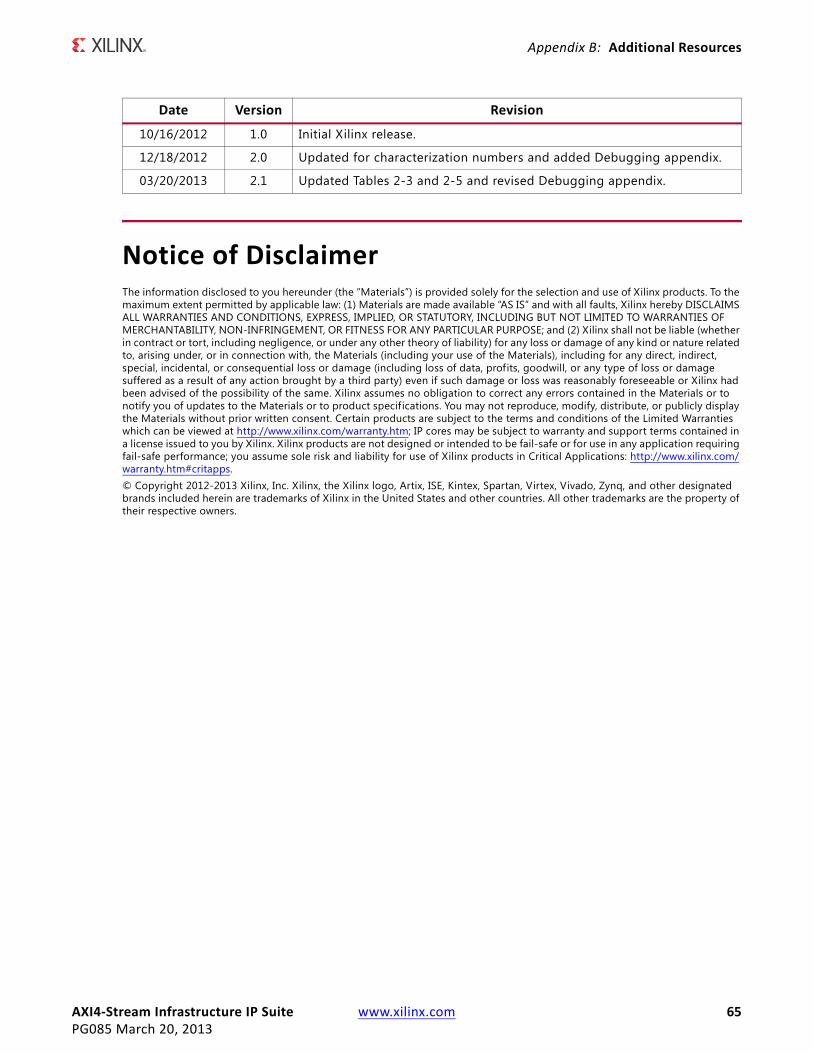
AXI4‐Stream Infrastructure IP Suite www.xilinx.com 65PG085 March 20, 2013
Appendix B: Additional Resources
Notice of DisclaimerThe information disclosed to you hereunder (the “Materials”) is provided solely for the selection and use of Xilinx products. To the maximum extent permitted by applicable law: (1) Materials are made available “AS IS” and with all faults, Xilinx hereby DISCLAIMS ALL WARRANTIES AND CONDITIONS, EXPRESS, IMPLIED, OR STATUTORY, INCLUDING BUT NOT LIMITED TO WARRANTIES OF MERCHANTABILITY, NON-INFRINGEMENT, OR FITNESS FOR ANY PARTICULAR PURPOSE; and (2) Xilinx shall not be liable (whether in contract or tort, including negligence, or under any other theory of liability) for any loss or damage of any kind or nature related to, arising under, or in connection with, the Materials (including your use of the Materials), including for any direct, indirect, special, incidental, or consequential loss or damage (including loss of data, profits, goodwill, or any type of loss or damage suffered as a result of any action brought by a third party) even if such damage or loss was reasonably foreseeable or Xilinx had been advised of the possibility of the same. Xilinx assumes no obligation to correct any errors contained in the Materials or to notify you of updates to the Materials or to product specifications. You may not reproduce, modify, distribute, or publicly display the Materials without prior written consent. Certain products are subject to the terms and conditions of the Limited Warranties which can be viewed at http://www.xilinx.com/warranty.htm; IP cores may be subject to warranty and support terms contained in a license issued to you by Xilinx. Xilinx products are not designed or intended to be fail-safe or for use in any application requiring fail-safe performance; you assume sole risk and liability for use of Xilinx products in Critical Applications: http://www.xilinx.com/warranty.htm#critapps.© Copyright 2012-2013 Xilinx, Inc. Xilinx, the Xilinx logo, Artix, ISE, Kintex, Spartan, Virtex, Vivado, Zynq, and other designated brands included herein are trademarks of Xilinx in the United States and other countries. All other trademarks are the property of their respective owners.
Date Version Revision
10/16/2012 1.0 Initial Xilinx release.
12/18/2012 2.0 Updated for characterization numbers and added Debugging appendix.
03/20/2013 2.1 Updated Tables 2-3 and 2-5 and revised Debugging appendix.