axial vibration analysis of thrust support of vertical
TRANSCRIPT
*Corresponding author’s e-mail: [email protected]
Axial Vibration Analysis of Thrust Support of Vertical Hydrogenerator Unit
Yuanlin Long*1, Yuping Ye1 1Datang Hydropower Science & Technology Institute, Chengdu,610073, Sichuan
Abstract. Axial vibration is the main accident that affects the normal function of the vertical hydro-generator unit and endangers the use of the unit. There are many reasons for the axial vibration of the unit. This article only analyzes the mechanism of the axial vibration of the thrust bracket of the vertical unit caused by the connection of the thrust head and the mirror plate, and gives a real machine measurement example and treatment measures.
1 Preface The lateral vibration of the guide bearing of the hydro-generator unit has received enough attention, while the axial vibration of the thrust bracket has not attracted people’s attention. Tests have shown that a small axial vibration amplitude is enough to damage the components of the unit and bring unstable factors to the operation of the unit.[1] Since the excitation of axial vibration comes from many aspects such as water flow, machinery,elevtromagnetics,etc. [2][3][4][5], it is difficult to determine the excitation parameters quantitatively,and the problem of axial vibration has not yet been satisfactorily resolved.This paper takes a real machine test of a vertical hydro-generator unit as an example, analyzes the mechanism of the axial vibration of the thrust support of the unit caused by the deformation of the insulating backing plate and the mirror plate, and proposes treatment measures, which provide some experience for the fault diagnosis of the unit.
2 Vibration mechanism analysis The weight and water thrust of the rotating part of the hydro-generator set act on the thrust bearing through the mirror plate connected by the thrust head. The thrust bearing is composed of several sector-shaped tiles with a certain gap between the tiles (Figure 1). Due to the unevenness of the insulating backing plate and the unevenness of the joint surface between the thrust head and the mirror plate, there is a gap between the thrust head and the mirror plate. When the gap is transferred to the thrust pad, the gap becomes smaller due to extrusion, the thrust pad is unloaded. When it turns to the thrust pad gap, it becomes larger due to slack, and the thrust pad is loaded at this time. This kind of loading and unloading alternately becomes an alternating force, and this alternating force causes the unit to produceaxial vibration. When the
unevenness of the insulating backing plate is two steps, it will form an axial vibration with a frequency of twice the speed.
3 Vibration test of a vertical hydro-generator unit
3.1 The source of the problem
A vertical shaft impact type turbine generator unit capacity 14000 KW, turbine type CJA575C-L-150/4 × 11, the rotational speed of 600r / min, the thrust tile 8. After the extended overhaul of the unit, the start-up test found that the upper frame (thrust support) of the unit had a large axial vibration when it was above 45 Hz, and it was high-frequency vibration. After disassembling the machine to adjust the force of the thrust pad, the level of the mirror plate and the axis of the unit, restart the machine, and the problem still exists.
E3S Web of Conferences 276, 02020 (2021) https://doi.org/10.1051/e3sconf/202127602020WCHBE 2021
© The Authors, published by EDP Sciences. This is an open access article distributed under the terms of the Creative Commons Attribution License 4.0 (http://creativecommons.org/licenses/by/4.0/).

3.2 Test methods
The test method uses eddy current sensors to measure the swing of the shaft at the upper guide bearing, lower guide bearing and water guide bearing, the radial and axial vibration of the upper frame (thrust support), and the radial vibration of the lower frame(Figure 2). The computer automatically collects and analyzes each frequency and amplitude characteristics of measuring points.
1-Axial vibration of thrust bracket 2- Spindle swing at upper guide 3-Radial vibration of thrust bracket 4- Spindle swing at lower guide 5- Radial vibration of lower frame 6- Spindle swing at water guide
Figure 2. Location map of measuring points
3.3 Test Results
Table 1 Variable speed process test data Unit: μm
Rotating speed(rpm)
Thrust bracket radial
vibration
Axial vibration of
thrust bracket
Radial vibration of lower frame
Spindle swing at
upper guide
Spindle swing at
lower guide
Spindle swing at
water guide
118.2 6.1 7.4 1.7 185.5 45 29.8 374.2 8.3 4.8 2.8 105.7 20 24.3 479.5 8.3 8.6 4.6 144.5 32.7 32.7 563.7 11.7 35.2 11.9 122.9 43.4 33 576.9 12.5 51.2 5.1 125.9 42.6 31 601.2 17.1 77.1 6.6 126.5 50.6 33.2
Table 2 Variable excitation process test data Unit: μm
Working condition
Thrust bracket radial
vibration
Axial vibration of
thrust bracket
Radial vibration of lower frame
Spindle swing at
upper guide
Spindle swing at
lower guide
Spindle swing at
water guide
Idling 18.4 86 6 122.5 53.7 33.7 25%ur 19.1 93.9 7 111.9 52.9 34.6 50%ur 18.7 94.3 6.1 115.1 50.6 34 75%ur 16.2 93.5 4 122.4 49.8 33.5
100%ur 14.7 88.4 6.9 119.7 49.2 33.6
2
E3S Web of Conferences 276, 02020 (2021) https://doi.org/10.1051/e3sconf/202127602020WCHBE 2021
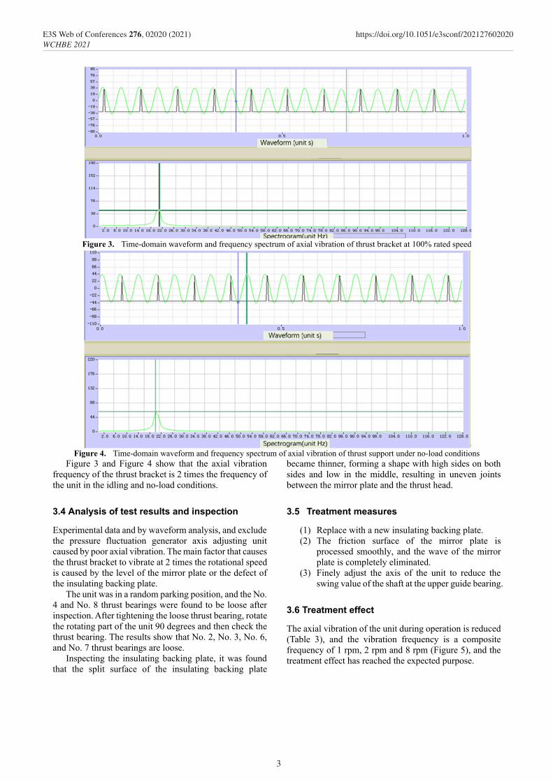
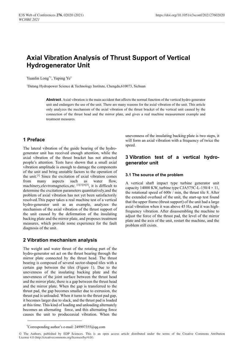
Figure 3. Time-domain waveform and frequency spectrum of axial vibration of thrust bracket at 100% rated speed
Figure 4. Time-domain waveform and frequency spectrum of axial vibration of thrust support under no-load conditions
Figure 3 and Figure 4 show that the axial vibration frequency of the thrust bracket is 2 times the frequency of the unit in the idling and no-load conditions.
3.4 Analysis of test results and inspection
Experimental data and by waveform analysis, and exclude the pressure fluctuation generator axis adjusting unit caused by poor axial vibration. The main factor that causes the thrust bracket to vibrate at 2 times the rotational speed is caused by the level of the mirror plate or the defect of the insulating backing plate.
The unit was in a random parking position, and the No. 4 and No. 8 thrust bearings were found to be loose after inspection. After tightening the loose thrust bearing, rotate the rotating part of the unit 90 degrees and then check the thrust bearing. The results show that No. 2, No. 3, No. 6, and No. 7 thrust bearings are loose.
Inspecting the insulating backing plate, it was found that the split surface of the insulating backing plate
became thinner, forming a shape with high sides on both sides and low in the middle, resulting in uneven joints between the mirror plate and the thrust head.
3.5 Treatment measures
(1) Replace with a new insulating backing plate. (2) The friction surface of the mirror plate is
processed smoothly, and the wave of the mirror plate is completely eliminated.
(3) Finely adjust the axis of the unit to reduce the swing value of the shaft at the upper guide bearing.
3.6 Treatment effect
The axial vibration of the unit during operation is reduced (Table 3), and the vibration frequency is a composite frequency of 1 rpm, 2 rpm and 8 rpm (Figure 5), and the treatment effect has reached the expected purpose.
3
E3S Web of Conferences 276, 02020 (2021) https://doi.org/10.1051/e3sconf/202127602020WCHBE 2021

Table 3 Vibration test data Unit: μm
Working condition
Thrust bracket radial
vibration
Axial vibration of
thrust bracket
Radial vibration of lower frame
Spindle swing at
upper guide
Spindle swing at
lower guide
Spindle swing at
water guide
150rpm 5.9 12.4 2.1 87.1 27.5 24.6 300rpm 4.8 4.1 1.1 79.3 21.4 26.8 450rpm 7.9 11 5 81.4 26.4 29.7 600rpm 8.1 9 4.6 91.6 27.7 30.6 No load 7.7 8.6 2.4 99.8 32.7 32.9
Figure 5. Time-domain waveform and frequency spectrum of axial vibration of thrust support under no-load conditions
4 Conclusion There are many factors that cause the axial vibration of a vertical hydro-generator set, including mechanical factors, hydraulic factors and electromagnetic factors. This article only focuses on the thrust bracket axial direction of the vertical hydro-generator set due to the defects of the insulating backing plate and the mirror plate among the mechanical factors. A preliminary study on vibration was conducted. Due to the strong destructive force of axial vibration, a small vibration amplitude is enough to damage the components of the unit. Therefore, it is necessary to conduct in-depth research on the axial vibration of the vertical hydro-generator set caused by other factors.
This article provides some experience on the installation, maintenance and axial vibration fault diagnosis of vertical units.
References 1. Dakun Yao, Jianwen Hu, Analysis and
Countermeasur on the Unit Vertical Vibration Caused by Thurst Bearing for Hydrogenerator , Big Motor Technology,1996 No.1:51-53.
2. Jingfang Jiang, Vibration of HL710 unit and improvement of air supplement, Hydropower
mechanical and electrical installation technology,1983 No.3:58-61.
3. Kaiji Huang, Stability Test of Unit 4 of Longyangxia Hydropower Plant, Hydropower,1992 No.9 35-36,40.
4. Shutang Tian, Chuanzhong Du etc. Vibration Test Analysis of Unit 1 in Shiquan Hydropower Plant, Proceedings of the 4th Asian International Conference on Fluid Machinery,1993.
5. Yuecan Tan et al, Research on Improving Hydraulic Stability of Francis Turbine in Tuoxi Power Station, Hydropower,1998 No.2 47-51.
4
E3S Web of Conferences 276, 02020 (2021) https://doi.org/10.1051/e3sconf/202127602020WCHBE 2021