az development of 8 a job sample trouble-shooting examination · on the construction of a...
TRANSCRIPT

aZ DEVELOPMENT OF
8 A JOB SAMPLE TROUBLE-SHOOTING EXAMINATION
rr. Serie« 1954 - Institute Report No. 1 15 January 1954
C3 GO
Prepared for
Office of Naval Research
United State« Navy
Under
Contract Number Nftonr-69402
John Jensen
Harry Kill
Arthur Siegel
Douglas Courtney
INSTITUTE FOR RESEARCH IN HUMAN RELATIONS PHILADELPHIA

THE DEVELOPMENT OF A JOB
SAMPLE TROUBLE-SHOOTING EXAMINATION
Progress Report
Series 1954, Institute Report #1
15 January, 1954
John J. Jensen J. Harry Hill Arthur I. Siegel Douglas Courtney
Prepared For
Office of Naval Research United States Navy
(Contract Number N8onr-69402)
INSTITUTE FOR RESEARCH IN HUMAN RELATIONS PHILADELPHIA WASHINGTON

INSTITUTE FOR RESEARCH IN HUMAN RELATIONS
ABSTRACT
This report describes the construction and content of a job sample trouble-shooting examination for aviation electricians. The job sample examination is based on the underlying processes followed by aviation electricians when they trouble-shoot on a piece of electrical apparatus. These underlying processes arej
1. Formulation of a series of hypotheses as to the cause of the malfunction.
2. Performance of actual electrical checks and equipment performance checks in order to substantiate or reject the hypotheses from (l) above.
3. Diagnosis of the cause of the malfunction from the information obtained frorr the electrical and equipment performance check3.
4. Performance of the actual work required to eliminate the cause of the discrepancy.
Four separate performance tests were developed, each of which measures the aviation electrician's achievement in one of these four areas. Since some of the skills involved in successfully completing the trouble-shooting battery are analogous to the skills involved in general electrical maintenance repair and replacement, it is believed that an aviation electrician's score on the battery also reflects his skill in these areas.
This project also developed and pretested a pool of items which may form the basis for the Ais Written Sxamination, the purpose of which ij to predict a trouble-shooting criterion.
At the outset the pool consisted of over 600 items. These items were administered to 399 aviation electricians on both the East and West coasts. The results from this test administration were analyzed. On the basis of this analysis the pool of items was reduced to 351 items. These 351 items are now ready for validation against the job sample trouble-shooting criterion.

INSTITUTE FOR RESEARCH IN HUMAN RELATIONS
ACKNOWLEDGMENTS
We would like to acknowledge the contributions of the many who helped to make this research possible.
First, the research could never have been completed without r.he full, cooperative support, given by Captain D. McCampbell, Commander C. Dodds, and other personnel at the Naval Air Technical Training Center, Jacksonville.
Other military personnel who deserve special mention are Lt. E. Dreiling and Lt. D. Huriong, who assisted in the organizing of the administration of the pool of items for the AE Written Examination, as well as Lts.G, Herndon and H, Pitcher, who helped clarify our thinking in regard to the trouble-shooting process.
The job sample trouble-shooting criterion could never have been com- pleted without the extremely valuable help of AEC G. Riley. Dr. Douglas Mayo at the Naval Air Technical Training Center, Memphis, made methodological suggestions throughout the research and helped to facilitate the statistical analyses.
Dr. W. C. Schaefer, Dr. F. K. 3errien and Dr. William H. Angoff made methodological and statistical suggestions throughout the research, and Dr. Berrien also critically reviewed the entire manuscript.
- 11 -

INSTITUTE FOR RESEARCH IN HUMAN RELATIONS
TABLE OF CONTENTS
Page No.
ABSTRACT , i
ACKNOWLEDGMENT? li
CHAPTER I - Introducti on and Overview ......... 1
CHAPTER II - Development of the AE Job Sample Trouble- shooting Examination — The Primary Criterion .. 3
CHAPTER III - Description of the AE Job Sample Trouble- shooting Examination ...................... 7
Sub-Test T 7
Sub-Test II 9
Sub-Test III 13
Sub-Test IV 16
Pretests 18
CHAPTER IV - The Development of the AE Written Examination 19
APPENDIX A - Sub-Test II 21
APPENDIX 5 - Scoring Sheet for Sub-Test IV 27
ill

INSTITUTE FOR RESEARCH IN HUMAN RELATIONS
CHAPTER I
INTRODUCTION AMD OVERVIEW
Effective electrical maintenance of the modern Naval aircraft has become of primary concern because effective flying is dependent upon such maintenance. Furthermore, this maintenance need will increase for the aircraft of the foreseeable future. More and mare, flight effectiveness and safety will depend upon the com- petence of the personnel in the Aviation Electrician*s Hate rating (AS). How well these personnel fulfill the demands made upon them det>ends, to a very great extent, on the validity of the procedures used for their selection, classification, assignment, and training.
The validity of these procedures may be determined only after a standard or a criterion of proficiency has been established. Such a standard has not existed for the AE. For that matter, less than 15 years ago the AS did not exist. Today, because of the number of personnel involved and the type of maintenance work performed, it is one of the most critical ratings in naval aviation. The increasing need for AEs over a short period of time did not allow for the normal evolvement of standards of workmanship. Personnel were brought into the AS rating fron surface and allied aviation ratings to fill the wartime needs. In conjunction, recruits from civilian life were given quick "massed" training which prepared them only for limited maintenance work on specific aircraft and equipment. Under these wartime conditions, it was impossible for adequate standards of electrical maintenance to develop.
Since the end of World ''Jar II, the section of the Manual of Quali- fications for Advancement in Rating (NavPers 18068 Revised) having to do with the AE rating was revised (effective 1 July 1953) to make it more applicable to the :naintenance of modem aircraft; standards and specifications for naval aviation electrical wiring and installations, such as Military Specifications, MIL-E-7080. were set down officially; and the Waval Air Technical Training program was revised to meet these standards. What wa3 still needed, however, was a means of determining how closely the personnel performing the electrical maintenance in the fleet approached these standards. The development of such a standard or criterion measure, the AE Job Sample Trouble-Shooting Performance Examination for the evaluation of this technical proficiency of AE, was the first major end product of the research here reported.
1 -

INSTITUTE FOR RESEARCH IN HUMAN RELATIONS
In many situations, the administration of the primary criterion, the AE Job Sample Trouble-Shooting Performance Examination, is not feasible because of personnel, time and material requirements. In order that a measure of known relationship with the primary criterion might be available for use in these situations, a start has been made on the construction of a paper—and-pencil test which will have a known correlation with the AE Job Sample Trouble-Shooting Performance Examination. The development of the items for this written test was the second major end product of the research here reported.
It should be pointed out, however, that these tests are measures of technical competence only. In no way can they be used to evaluate the AE as an instructor, as a leader, or in other such capacities.
- 2 -

INSTITUTE FOR RESEARCH IN HUMAN RELATIONS
CHAPTER II
DEVELOPMENT OF THE AE J03 SAMPLE TROUBLE-SHOOTING
EXAMINATION — THE PRIMARY CRITERION
The degree of success with which most Naval aviation activities carry out their missions is dependent to a considerable degree on the level of availability of their aircraft. The level of availability is, in turn, dependent on proficient maintenance of the aircraft. For this reason, the ultimate criterion of tech- nical proficiency for the AE is the actual performance of correct electrical maintenance in operating activities.
Since it is currently impossible to obtain an objective measure- ment of on-the-job performance in all operating activities, the next best method is a sample of the AE's performance from which his total proficiency can be inferred.
The AE Job Sample Trouble-Shooting Examination, Form 1
In order to develop a realistic job sample, it was first necessary to define the AETs job in terms of what he does and the best method of doing it. Records and personnel of operating fleet squadrons were the logical sources of this information. From electrical shop maintenance logs, it was possible to determine what the maintenance job consists of and what the AE is supposed to do. Extensive interviews with AEs in the first three pay grades revealed what they considered the best methods.
These sources showed that "trouble-shooting" is the critical type of maintenance performed by the AE. While it is not necessarily the major portion of the .fork, trouble -shooting is considered to be the ability that distinguishes between the proficient and the unproficient. For this reason the examination was built around trouble-shooting problems.
The first step was to compile lists of trouble-shooting problems that actually occurred in operating activities and the procedures that were used to solve them. On the supposition that these procedures were correct, a start was made on constructing a trouble- shooting job sample examination.
- 3 -

INSTITUTE FOR RESEARCH IN HUMAN RELATIONS
During the course of collecting the Information for the construction of the job sample examination, the personnel interviewed were asked to nominate the best authorities on the duties of the AE rating who could act as final judges on the acceptability of the measure. Two experienced officers were named as clearly best qualified in this respect.
After the examination was completed, it was submitted on an informal basis to these two experts for their opinions as to the acceptability of the examination as a measure of technical proficiency for the AE. The experts did not find the examination acceptable.
Their major criticism was that the procedures used in the job-sample to determine the cause of discrepancies - observing the discrepancy and then making an "educated gü-ss" a: to the cause - were not correct, although these procedures are in common use in operating activities. In tve opinions of these experts this is one of the great maintenance evils in many of the operating activities.
They pointed out that such methods of troubie-shocting, while very efficient in some cases, with respect to the time required to locate the discrepancy, are very uneconomical in the use of material and, in the long run, even in use of time. Furthermore, this "educated guess" method of maintenance is considered one of the primary reasons why much electrical equipment in perfect working order is turned into supply as damaged or defective; i.e., the guess is incorrect.
AE Job Sample Examination - Form II
The experts who rejected Form I of the AE Job Sample Trouble- Shooting Examination, supplied their definitions of the AE's job. The experts agreed that trouble-shooting is the ability that distinguishes between proficient and unproficient AEs, and also suggested the analysis which follows as a systematic approach to trouble-shooting. This systematic approach is preferred over the "educated guess" method.

INSTITUTE fOR RESEARCH IN HUMAN RELATIONS
Analysis of Trouble-Shooting
To locate by system analysis and remedy the cause3 of malfunctions in any given system the AE musts
1„ Hypothesize as to the cause of the malfunction.
To do this, the AE must have complete knowledge of the purpose and operation of the individual components of the system in question, the purpose and operation of the system as a whole, any interactions between the system in question and ether systems, and the purpose and operation of the testing instruments and equipment to be used.
2„ Perform actual electrical checks and equipment performance checks in order to substantiate or reject the hypotheses from (1; above..
The minimum requirements here are the utilization, in accordance with the Equipment Operation and Service Instructions and the Aircraft Handbook of t-'ainter.ance Instruction,, of testing instru- ments, equipment, and equipment performance chart3 to check the components and pertinent systems,,
3» Diagnose the cause of the malfunction from the information obtained in the electrical and equipment performance checks.
Here the AE mentally synthesizes the results from the second part with his pre-check hypotheses and deduces the cause of a malfunction.
4. Perform the actual work required to eliminate the cause of the discrepancy»
This involves skills and abilities in the use of hand and power tools, and equipment required to remove, install, adjust and repair the wiring and components of electrical systems in accord- ance with the Equipment Operation and Service Instructions and the Aircraft Handbook Maintenance Instructions,,
- 5

INSTITUTE FOR RESEARCH IN HUMAN RELATIONS
Although these four steps are necessary to correct electrical discrepancies, the skills and abilities underlying the steps do not differ from those needed in preventive maintenance and service changes. Comparison also shows that the skills and abilities required of the AE as stated above are at least implicit in these four work steps. Therefore, it is at least partly correct that the AE who can effectively trouble-shoot can also effectively perform these duties. A description of tne AE Job Sample Trouble-Shooting Examination is presented in Chapter III.
The AE Job Sample Trouble-Shooting Examination was constructed in four parts corresponding to the four steps necessary to locate by system analysis and remedy the cause of electrical discrepancies. It should be pointed out, however, that while two of these parts may appear to be paper-and-pencil tests, the paper-and-pencil aspect is merely a means of recording the AE's reasoning - the mental operations he performs in these steps.

INSTITUTE FOR RESEARCH IN HUMAN RELATIONS
CHAFTER III
DESCRIPTION OF THE AE JOB SAMPLE PERFORMANCE EXAMINATION
Sub-Test I - Determination of Possible Causes of Trouble
In order to test the AE's ability to formulate hypotheses on possible causes of electrical malfunctions, 24 discrepancies with accompanying wiring diagrams were assembled. For each discrepancy a list of possible causes was also gathered. The task of the examinee is to select those causes which could be responsible for each discrepancy. Sample items (wiring diagrams omitted) follows
Discrepancy 1
Left aileron motor does not run with the control switch closed. There is normal operation on the right pump.
Proposed Causes
1. Wire CS38A18N has high resistance at the ground terminal.
2. Very low resistance at the ground terminal on wire CS3C4N.
3. Thermal switch contact has infinite resistance.
4. Control coil in main contact has connections reversed.
5. Wire CS7A18N installed on terminal "!•!'» by mistake.
6. Condensor «fire CS3B18N is open.
7. Condensor 1414 plates shorted together.
Discrepancy 3
Left starter will not energize. (Starter motor was bench checked and operation found to be normal.)
Proposed Causes
1. Fuse is blown.
- 7 -

INSTITUTE FOR RESEARCH IN HUMAN RELATIONS
2. Circuit breaker is open.
3. Open circuit on lead coming from power circuit to relay contacts.
4. Wire from circuit breaker is off of switch.
5. Fuel oil shut off switch has high resistance across contacts.
6. High resistance at solenoid terminal.
7. Open at ground terminal on power relay.
8. Open circuit on lead from fuse to power side of starter solenoid.
9. Ground lead from solenoid is broken.
Discrepancy 13
Invertor does not turn up.
Proposed Causes
1. Potentiometer shorted out.
2. Pitted stacks.
3. Open resistor.
4. Open ground leads.
5. Wire No. XV4A12 is open at the terminal.
6. Open in wire No. XP5A20.
7. Five ampere circuit breaker open.
8. Wire No. XP360 disconnected at the terminal strip.
9. Wire No. XP360 disconnected from positive terminal.

INSTITUTE FOR RESEARCH IN HUMAN RELATIONS
Development of Sub-Test I
Entries made over a three month period in five electrical shop maintenance logs were analyzed to determine relative frequencies of various discrepancies. From this analysis 39 typical dis- crepancies evolved. Three chief aviation electricians separately rated each of the 39 discrepancies according to pay grade and applicability of rating structure as stated in NavPers 18068 (Revised). On the basis of these judgments and further discussion, fifteen discrepancies were eliminated as too hard or easy for a given pay grade; or as not required by the new rating structure. The final 24 discrepancies included six which were at a difficulty level appropriate for each of four Naval pay grades and were representative of several plane types.
Sub-Test II - Performance of Checks
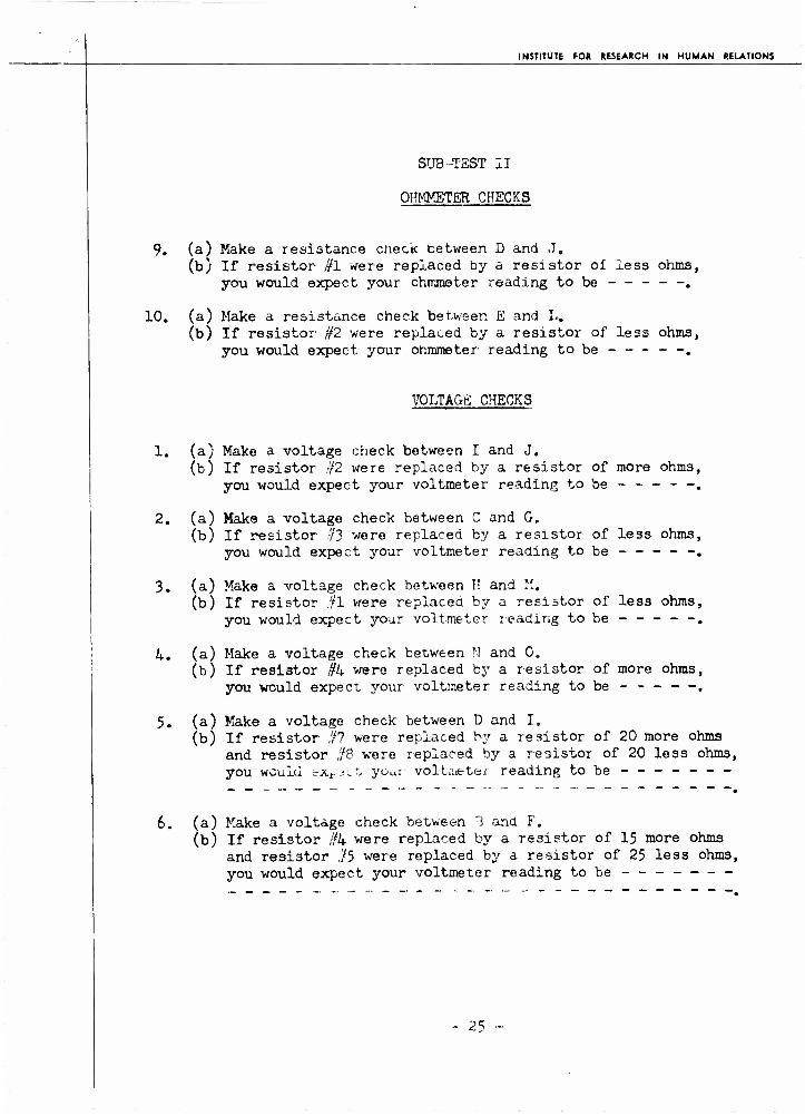
In order to test the aviation electrician*s ability to perform the electrical checks necessary to substantiate or reject hypotheses on the causes of discrepancies, the Electrical Checks Testing Box (Figure l) was constructed. This is a wooden box 18-1/2" x 12" x 3" covered by a metal lid. On the lid are three rows of five terminals connected in a series-parallel circuit with resistors included. The terminals are insulated from the metal lid and are connected by metal strips which form the circuit. Metal strips have been used instead of wires, because they have minimal resistances of their own, and because of the convenience with which resistors can be used with this type of conductor. This circuit simulates the type of live circuits found in operational aircraft. Current is supplied by an ex- ternal source of power such as an APU (Auxiliary Power Unit) or a battery.
The task of the examinee is to perform a series of electrical checks on the box using tne mulüimetejc as a check instrument. The letters (Figure l) designate terminals at which readings are to be taken. The numbers denote the resistors. Following each check the examinee is <?sked a question which probes into whether he understands the principles upon which electrical circuits operate. Sample items ares
9 -

X &
c •H +i n •
iH n
% 1 •H O
t-i « •H
Ü V

INSTITUTE FOR RESEARCH IN HUMAN RELATIONS
Item 1. (a) Make a resistance check between I and J. Reading In Ohms ,
(b) If resistor //6 were replaced by a resistor of less ohms, you would expect your ohmmeter reading to be (the same) (greater) or (less).
Item 6. (a) Make a voltage check between D and I. Reading in Volts ,
(b'l If re si 3t or Ifl were replaced by a resistor of 20 more ohms and resistor ,'i& were re- placed by a resistor of 20 less ohms, you would expect your voltmeter reading to be (the same) (greater) or (less).
An understanding of the principles upon which electrical circuits operate is fundamental to effective eieetrica^. maintenance. For instance, let us suppose that two lights?, A and 3. are connected in parallel. light A is not burning; Light B is burning less bright than normally. Upon finding Light A out, it is reasonable for the AS to assume tnat it r.as burned out.. This would increase the resistance. However, assuming a parallel circuit, this means that Light B should now burn more brigrtly. since it is carrying increased current. However, Light B if not burning brighter, but dimmer than normally. Hence, the conclusion is tnat the source of power is not putting out the required voltage. A voltmeter reading will confirm or deny this conclusion.
In summary, sub-test II yields information in regard tos
1. The AEfs ability to use and read testing instrument.
2. The Aüs s under^andm^ oi tue principle upon which electrical circuits operate.
Development of Sub -Test II
In order to determine which of the many testing instruments used by the aviation electrician would be most acceptable for purposes of this examination, an attempt was made to find an instrument that met the criteria of;
10

INSTITUTE FOR RESEARCH IN HUMAN RELATIONS
1. Importance during actual trouble-shooting process.
2. Adaptability to testing purposes,
3. Availability at the squadron level.
A list of testing instruments used by the AE wa3 compiled by two Chief Petty Officers. The chiefs used personal experience, con- sultation with other chiefs, and service change manuals as the basis for their list. The list of instruments was then checked for completeness by a third chief. The instruments on the final list were;
1. Multimeter 2. AC voltmeter 3. DC "oltm«ter 4. Ammeter 5. Megger 6. Wheelco Tester '^thermocouple tester) 7. Generator vari-drive panel P. G-l automatic pilot tester 9. Portable Scorsly tester
10. Red Star field test set 11. C-l field test set 12. Ignition harness tester 13. Gyro flux gate compass test, kit 14. P-l automatic pilot field tester 15. Field variable capacitance tester 16. Autosyn functional tester 17. Remote compass tester 18. Liquidometer 19. Turn and bench tester 20. Dead weight tester 21. Selsyn instrument tester 22. Thermometer test 23. Frequency meter 24. Wattmeter 25. Strobatic 26. Oscilloscope 27. Tube tester
11

INSTITUTE FOR RESEARCH IN HUMAN RELATIONS
Seven chiefs were separately asked to select from the list the five "most important" testing instruments required for performing the duties of the aviation electrician. Most important was defined in terms of;
1. Relative frequency of use of the instrument during trouble-shooting.
2. Criticainess of the instrument for performing the duties of the aviation electrician.
3. Actual operational usage of the instrument at the squadron level.
The three instruments which were most frequently chosen as one of the five "most important" wer6.
1. Multimeter (7) 2. General vari-drive test panel (U) 3. Red Star field test set (3)
A further intensive discussion was held on the merits of these three testing instruments in the light of the criteria. This resulted in the elimination of the generator vari-drive and the Red Star field test set. The generator vari-drive was eliminated because usually only one generator vari-drive is assigned to a squadron. Moreover, this piece of apparatus weighs approximately 300 pounds and is, therefore, impossible to carry around for testing purposes. Most important, however, is the fact that the generator vari-drive is not actually used in the trouble-shooting process but is used to correct a discrepancy after it is diagnosed. The Red Star field test set was eliminated because the set is composed of many tools and instruments each of which could form the basis of a separate test and because the tools in the set are not a means for testing circuits but rather a means for fixing a discrepancy. Multimeters, therefore, became the sole testing instrument employed.
Construction of Circuit
A chief aviation electrician cooperated with the Institute personnel during the construction of the AE Job Sample Trouble- Shooting Examination. This chief devised the series-parallel circuit and 10 ohmmeter, 10 voltmeter, and 10 ammeter problems for the circuit. Two other chiefs then checked the problems for accuracy and wording.
- 12 -
INSTITUTE FOR RESEARCH IN HUMAN RELATIONS
The particular series-parallel circuit was made up in the form shown in Figure 1 and is called the Electrical Checks Testing Box. It provides a level of complexity suitable for examination purposes. The wiring box has the advantage that it exposes a whole series- parallel circuit to the examinee. This exposure would be impractical on an aircraft. The questions were devised so that they cut across all pay grades and were worded so that the examinee was not required to know the value of the resistors in order to solve the problems.
Sub-Test II in its entirety is presented as Appendix A of this report.
Sub-Test III - Diagnosis of Malfunctions
In sub-test III a man is given a discrepancy, plus the results of some checks. His task is to determine the one cause of the trouble.
Typical problems (wiring diagrams omitted) follow. A total of 24 similar problems are included in the test.
Discrepancy 1 (Wiring Diagram 1)
The left engine cylinder temperature indicator reads 20° lower than the right indicator. A calibration check of left indicator with a Wheelco cylinder temperature tester proves it to be properly calibrated.
Which one of the following is the cause of this discrepancy?
1. Low resistance between plus and minus of indicator leads.
2. A short in the right variable resistor. 3. The left variable resistor adjustment has
slipped to low side. 4. Corrosion in the left firewall plug. 5. A break in B load at the left firewall plug. 6. Open in Y lead between left firewall plug and
thermocouple„
- 13

INSTITUTE FOR RESEARCH IN HUMAN RELATIONS
Discrepancy li (Wiring Diagram jl)
Low generator output. Generator warning light burns con- tinuously. Voltage reading between GEM terminal of reverse current relay and ground is If* volts with engine turning up at 1400 R.P.M.,
Which one of the following is the cause of this discrepancy?
1. Plus and minus leads at voltmeter reversed. 2. Open between E of generator and ground. 3. High resistance between F+ and G+ of voltage
regulator, 4. Internal short in reverse current relay between
NEG and 3AT terminals,, 5. Open between L+ and L_^ of voltage regulator. 6. High reoictanoti v etwee r. iJEG ana SW terminals of
reverse current relay.
Discrepancy 24 (Wiring Diagram 23)
The P-l auto pilot fails to operate when auto pilot switch is turned on and clutch switch is pushed in. Movement of controller knobs causes no servo movements. Clutch switch knob remainsMin"when pushed'^n? All tubes of amplifiers are burning.
Given the above winch one of the following is the cause of this discrepancy?
7. Short between F113K22 an<: F140A22 at gyro horizon control plug.
8. Short between terminals 8 and 9_ of caging relay. 9. Short between F120A22 and F121A22. 3etween con-
troller 'JT box and amplifier. 10. Lead F129A22 is open at amplifier plug. 11. Open in lead F6PA22 at amplifier plug. 12. Open between I of aileron servo and ground.
14

INSTITUTE FOR RESEARCH IN HUMAN RELATIONS
Criteria for Inclusion of Particular Discrepancies
On the basis of an analyses of erection and maintenance manuals, service change manuals, and the electrical shop maintenance logs of five squadrons, a comDrehensive list of discrepancies was first drawn up. These discrepancies were then screened according to the following criteria?
1. Major systems involved in AE maintenance work.
2. Variability among types of aircraft.
3. Difficulty level.
1. Major Systems Involved in AE Maintenance Work
Using the List of Military Specifications and Standards of the Bureau of Aeronautics as a guide,, the field of AE maintenance work was broken down into six major areas. These six major areas were:
1. DC power sappiy and control
2. AC power supply and control
3. Interior and exterior lighting
4. Power plant
5. Instruments
6. Special materials and equipment
The analysis of entries made by the five squadrons in their electrical shop maintenance logs over a three month period revealed that their discrepancies were about equally divided between the first four and the last two areas» With this as a basis, it was decided that sub-test III should contain three discrepancies in each of the first four areas and six discrepancies in each of the last two areas.
- 15 -

INSTITUTE FOR RESEARCH IN HUMAN RELATIONS
2. Variability Among Airplanes
Aircraft can be classified generally as being of one of three types - single reciprocation engine, multi-recip- rocation engine, and jet engine. Current Naval aircraft were categorized by a chief using erection and maintenance manuals as guides into these classes. The categorization was checked over for completeness and accuracy by a second chief. Discrepancies from as many aircraft and aircraft types as possible are included in sub-test III. In this manner no examinee is unduly penalized because of unfamiliar- ity with a single aircraft type.
3. Difficulty Level
The pay grade lave2 of e^ch discrepancy was determined in the following manner. The list of discrepancies was pre- sented to five separate chiefs. The" chiefs were well grounded in the requirements of NavPers 18068 (Revised) and with this as a guide, graded each discrepancy as to pay grade level. A comparison of judgments eliminated many discrepancies as too simple or too complex for a given pay grade.
The distribution of discrepancies by plane type, pay grade level and system represented in the final test is presented in Table 1.
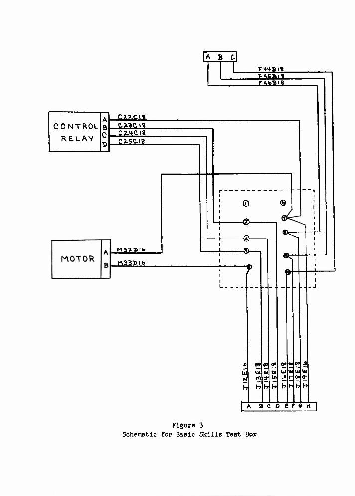
Sub-Test IV - Performance of Manual Skills
The purpose of sub-test TV is to test the AE on his ability to perform the actual work required to eliminate the cause of a discrepancy, once the cause has been ascertained. In order to test this ability the Basic Skills Test Box was constructed. Figure 2 shows two Basic Skills Test Boxes joined together. The box simulates in miniature an aircraft section and the components found therein. A simulated motor, control relay, control cable, ribs, lightening holes, fuel line and junction box are included. The inside of the box is zinc chromated and the components labeled. Holes one inch apart are drilled throughout the periphery of the device. The purpose of these holes is t~ permit the AE to attach clamps as needed. The task of the examinee is to solder wires to the 8-pin cannon plug and to run the wires through their components as
- 16

CO
I a
CM p
C U m i a
n

INSTITUTE FOR RESEARCH IN HUMAN RELATIONS
Table I
Distribution of Discrepancies by Pay Grade Level, System and Plane Type in Sub-Test III
Name of Airplane Type of Plane* Pay Grade Systems Represented
P2V-6
P2V-5
AD-4
AM-1
AJ-1
PBM-5A
P5M-1
F9F-5
F4U-5
F3D-2
AJ-2P
AJ-2P
M
M
S
S
M
M
M
S-J
s
M-J
M
M
E-6 DC Power Supply & Control E-5 AC Power Supply & Control E-6 Instruments E-3 Instruments E-4 Special Materials & Equipment E-5 Special Materials & Equipment
E-4 Power Plant E-3 Power Plant
E-4 DC Power Supply & Control
E-4 DC Power Supply & Control E-4 AC Power Supply & Control
E-5 AC Power Supply & Control
E-3 Interior & Exterior Lighting
E-3 Interior & Exterior Lighting E-5 Instruments E-6 Special Materials & Equipment
E-3 Interior & Exterior Lighting E-5 Power Plant E-4 In st rument s
E-4 Instruments
E-5 Instruments E-6 Special Materials & Equipment
E-6 Special Materials & Equipment
E-6 Special Materials & Equipment
* M * Multi engine S - Single engine S-J - Single Jet M-J - Multi Jet
- 17 -
INSTITUTE FOR RESEARCH IN HUMAN RELATIONS
indicated on a schematic (Figure 3). The skills involved in the successful completion of this task are soldering, use of tools, knowledge of the principles of safe wiring, selection of the proper size nuts, bolts, clamps, wires, etc., reading and working from schematic wiring diagrams, employment of insulating tech- niques, fabrication of cables, installation of terminal strips, and connections, etc. These are the actual skills used in repair- ing or replacing a defective component in the operational situation.
Scoring
The scoring sheet used in conjunction with this test is presented in Appendix B. It can be seen that the examinee is scored in this test on the quality of his final product. The emphasis in scoring is based upon the consensus of opinion of four chief aviation electricians who were thoroughly indoctrinated in the test task and its purpose. These chiefs were asked to rate each area scored on the basis of five, ten, or fifteen points. If three of the four chiefs agreed on the weight of a given area that emphasis was accepted as the weight assignable to the area in question. If two of the chiefs assigned one weight to an area and the other two chiefs assigned another weight, an average was then taken as the scoring emphasis for that area.
Pre-Test of the AE Job Sample Performance Examination
All four sub-tests in the AE Job Sample Trouble-Shooting Examination were pre-tested on from five to twelve examinees. As a result of the pre-testing, examinee and examiner in- structions were clarified, time limits were revised, equipment was modified, and unclear wordings and technical errors which escaped the proof reading of the chief petty officers were revised.
The complete AE Job Sample Trouble-Shooting Examination is now revised and ready for administration in the fleet situation.
- 18 -
ABC
F14BI? MfiSl? Fm»3H
CONTROL
RE.LAV
cxa-cn Q3C.H CAiClf C2.sai8
f\33t.T>H»
KV33T>lb
© ©
-®- -®-
h H
tu 10
•^
fr
h b
o» ff e»
0« ^
A B C D E F G H
Figur« 3 Schematic for Basic Skills Test Box

INSTITUTE FOR RESEARCH IN HUMAN RELATIONS
CHAPTER IV
THE OEVEIOFMENT OF THE AE WRITTEN EXAMINATION
Because the job-sample performance examinations are difficult to administer routinely a substitute measure is necessary to measure job proficiency. For this purpose a multiple-cnoice written examination is usually the most valuabler provided it is correlated with job sample scores. Accordingly, a pool of about 351 item3 was developed.
The AE Item Pool
To obtain the large number of items necessary for development of the pool, two major sources were usedj the examination files of the AE School, NATTC, Jacksonville, and the 4 January 1952, AE 1, 2, and 3, Advancement in Rating Examinations. Five chief petty officer instructors at the AE Schools selected the items. In all, 655 multiple-choice item3 were obtained from these two sources.
These items were administered to 3?9 AEs who were about equally divided between Pacific Coast and Atlantic Coait activities. A breakdown of this sample by pay grade is shown in Table 2.
Table 2
Distribution by Pay Grade of AE's Who Took 665 Items
Pay Grade Number
E-6 29 B-5 32 E-4 156 E-3 182
TOTAL 399
From the results of this administration, an Index of the difficulty level of each item was obtained. Each incorrect response (dis- tractor) was also analyzed in terms of the number of examinees attracted to it. Item-test correlations were obtained from each item. Items with difficulty level3 greater than .95 or less than
19
INSTITUTE FOR RESEARCH IN HUMAN RELATIONS
.05 were eliminated from the pool."' Distraetors which attracted too many or too few responses were rewritten in some cases and in other cases the items containing these distraetors were eliminated from the pool. Items with low or negative item-te3t correlations were also discarded.
While the item analysis was being made, the revision of the AE qual- ifications in NavPers 18063 became effective. Simultaneously it became apparent that there was a need for a pool of items which would be applicable for testing in order to predict success in the various phases of the AE "B" school. Therefore five chief petty officers were asked to review the items in order to determine their applica- bility under the newly revised rating structure as well as their ap- plicability to "3" school phases. In some instances no items related to the 53 examination subjects listed in sections 202 and 203, for the AE in th<» reviser* "*TrP«rg IPOAO whi?.e for other subjects there were as many as 66 items. It was, therefore, necessary that some new items be written and other items be eliminated to obtain even cover- age across subject categories. Five officers and warrant officers with long experience with AE work added items to those subject areas that were not adequately sampled. Because of time and personnel requirements these new items were not pre-tested or analyzed.
Future Research
The revised pool of items, all of which relate by content to examination subjects of the revised NavPers 18063 as well as to the phases of WB" School, is now ready for administration in order to determine how these items relate to the AE Job Sample Trouble-Shooting Examination. In the next phase of the research, there will also be a determination of the relationship between AE "A" School grades and fleet proficiency as measured by the AE Job Sample Trouble-Shooting Examination. More- over, the items in the pool will be categorized according to the phases of the AE "B" School, and norms worked out, if possible by pay grade, for each c-.tcgory. The relationship between the AE Job Sample Trouble-Shooting Examination and Basic Battery Test Scores, as well as the relationship between the Job Sample Examination and the com- petitive advancement in rating examination, may also be determined.
* To conserve space the item analysis data are not included in this report. They can be obtained, however, on inter-library loan from The Records Librarian, Institute for Research in Human Relations, 2224 Locust Street, Philadelphia, Pa„
- 20
INSTITUTE FOR RESEARCH IN HUMAN RELATIONS
APPENDIX A
In Appendix A is presented Sub-Test II of the AS Job Sample Trouble-Shooting Examination,, It is not possible to present Sub-Tests I and III in their entireties because these sub- tests contain security information.
21 -

INSTITUTE FOR RESEARCH IN HUMAN RELATIONS
INFORMATION SHEET - SUB-TEST II
WHAT IS THIS BOX?
On the lid of this box is a series-parallel circuit made of metal strips. Resistors are included in the circuit. The circuit is the same as any wiring circuit, for it can carry electricity.
WHY USE METAL STRIPS INSTEAD OF ACTUAL WIRES?
1. The metal strips have no resistance of their own; therefore, they won't affect your readings with the multimeter.
2. This type of box makes it ea3y to give clear and simple instructions.
3. The points at which you take readings are more accessible. 4. The box is sturdy, and can take a beating. Don't abuse the
privilege however.
WHAT IS THE PURPOSE OF THIS TEST?
1. Whether you know how to use the multimeter. 2. To determine whether you know how to reason, when presented
with actual problems on a circuit. A reading doesn't mean much, unless you can interpret its implications.
WHAT AM I SUPPOSED TO DO?
You will be given a sheet with problems and spaces for filling in answers.
Let us look at the example on sheet #1. First it says: "Take an ohmmeter reading between B & C." You can see there is a realste* betv/er.i thoso points. You will obtain a readin«? of A. 5 ohms. You can see the man marked 45 ohms in Example A. , The second part of the question says» "If resistor ffl was replaced by a resistor of less ohms, you would expect this reading to be the (same, higher, lower) than the reading vou actually obtained. As you can see the man wrote in the word "Lower".
- 22 -

INSTITUTE FOR RESEARCH IN HUMAN RELATIONS
WHY IS IT LOWER?
If there were less resistance between points B and C, then you would get a lower ohmmeter reading. Therefore, the reading you would expect would be lower than the one you actually obtained with your multimeter.
You will have 10 ohmmeter problems and 10 voltmeter problems.
USE YOUR HEAD!
Sometimes your answer might be the same or higher. Check the appropriate box!!
HOW MUCH TIME DO I HAVE?
ONE HOUR - This is more than you probably will need. So do careful, correct work. Your readings must be accurate to within ±5£~
ANSWER ALL QUESTIONS!!
- 23 -

INSTITUTE FOX RESEARCH IN HUMAN RELATIONS
SUB-TEST II
OHMMETER CHECKS
Example: A/x-i (a) Make a resistance check between B and C. (fr**J (b) If resistor #1 were replaced by a resistor of less ohms,
you would expect your reading to be the (same, higher, lower) than your original ohmmeter reading. Jt'^u^t^J
1. fa) Make a resistance check between I and J. (b) If resistor #6 were replaced by a resistor of less ohms,
you would expect your ohmmeter reading to be - -.
2. (a) Make a resistance check between I and N. (b) If resistor #8 were replaced by a resistor of more ohms,
you would expect your ohmmeter reading to be .
3. (a) Make a resistance check between A and I. (b) If resistor #2 were replaced by a resistor of less ohms,
you would expect your ohmmeter reading to be .
4. (a) Make a resistance check between H and M. (b) If resistor #3 were replaced by a resistor of more ohms,
you would expect your ohmmeter reading to be .
5. (a) Make a resistance check between C and E. (b) If resistor #4 were replaced by a resistor of more ohms,
you would expect your ohmmeter reading to be .
6. (a) Make a resistance check between H and 0. (b) If resistor #1 were replaced by a resistor of less ohms,
you would expect your ohmmeter reading to be —.
7. (a) Make a resistance check between B and G. (b) If resistor #5 were replaced by a resistor of less ohms,
you would expect your ohmmeter reading to be .
8. (a) Make a resistance check between F and M. (b) If resistor #7 were replaced by a resistor of more ohms,
you would expect your ohmmeter reading to be .
- 24 -
INSTITUTE FOR RESEARCH IN HUMAN RELATIONS
SUB-TEST II
OHMMETER CHECKS
9. (a) Make a resistance check cetween D and J„ (b) If resistor #1 were replaced by a resistor of less ohms,
you would expect your ohmmeter reading to be - - - - -.
10. (a) Make a resistance check between E and L. (b) If resistor #2 were replaced by a resistor of less ohms,
you would expect your ohmmeter reading to be ,
VOLTAGE CHECKS
1.
2.
3.
4.
5.
6.
(a) Make a voltage check between I and J. (b) If resistor ,-/2 were replaced by a resistor of more ohms
you would expect your voltmeter reading to be ----- -
(a) Make a voltage check between C and G. (b) If resistor ,;/3 were replaced by a resistor of less ohms
you would expect your voltmeter reading to be
(a) Make a voltage check between II and ". (b) If resistor ,fl were replaced by a resistor of less ohms
you would expect your voltmeter reading to be
(a) Make a voltage check between N and G„ (b) If resistor /fU were replaced by a resistor of more ohms
you would expect your voltmeter reading to be
(a) Make a voltage check between D and I. (b) If resistor ,'/? were replaced by a resistor of 20 more ohms
and resistor ff8 were replaced by a resistor of 20 less ohms, you would ".X.J-1- % your voltmeter reading to be -------
(a) Make a voltage check between 1 and F. (b) If resistor //4 were replaced by a resistor of 15 more ohms
and resistor ,!'5 were replaced by a resistor of 25 less ohms, you would expect your voltmeter reading to be -------
- 25

INSTITUTE FOR RESEARCH IN HUMAN RELATIONS
SUB-TEST II
VOLTAGE CHECKS
7. (a) Make a voltage check between M and N. (b) If resi3tor //6 were replaced by a resistor of more ohms,
you would expect your voltmeter reading to be .
8. (a) Make a voltage check between E and J. (b) If resistor //3 were replaced by a resistor of less ohms,
you would expect your voltmeter reading to be - - - - -.
9. (a) Make a voltage check between C and M. (b) If resistor #7 were replaced by a resistor of 50 less ohms
and resistor #3 were replaced by a resistor of 50 more ohms, you would exp?ct yo':r voltir.ster reading to be -------
10. (a) Make a voltage check between G and H. (b) If resistor #3 were replaced by a resistor of 25 more ohms,
you would expect your voltmeter reading to be ------.
26 -

INSTITUTE FOR RESEARCH IN HUMAN RELATIONS
APPENDIX B
In Appendix B is presented the scoring sheet for Sub-Test IV of the AE Job Sample Trouble-Shooting Examination.
- 21 -

INSTITUTE FOR RESEARCH IN HUMAN RELATIONS
APPENDIX B
SCORING SHEET FOR SUB-TEST 17
SOLDERING;
1. Are leads hand tight? (Pull by hand) Minus 1 point for each loose lead.
2. Has solder shorted two terminals? (Visually inspect) Every two terminals shorted - Minus 1 point.
3. Are ends of wire3 near soldering points burned? Each burned wire - Minua 1 point.
4. Is it a neat job? Solder splashed in box or around spaghetti - Minus 3 points.
SPAGHETTI:
5. Doe3 each lead at plus; or receptacle have spaghetti? Each missing piece - Minus 1 point (Maximum 8 points).
6. Is spaghetti at 8 pin cannon plug tied - Minus 2 points if not tied.
JUNCTION BOX;
7. Are lugs securely held by nuts on terminals? (Test by hand) Each loose nut - Minus 1 point (Maximum 8 points).
8. Are wires lashed before each branch off to new terminal? Minus 1 point for each branch not lashed. (Maximum 3 points),
9. Do wires pull loose from lugs? Each loose lead - Minus 1 point.
10. Have lugs been broken by improper crimping? (If wires have been pulled loose in item //9. count only remaining lugs.) Each broken lug - Minus 1 point.
28

INSTITUTE FOR RESEARCH IN HUMAN RELATIONS
11. Is insulation flush with the lug? Each bare wire - Minus 1 point (Maximum 8 points).
LASHINGs
12. Do knots flick open with thumb nail test? (Spot check five knots in a row) Each loose knot - Minus 1 point (Maximum 5 points).
13. Are knots spaced 5" or more apart? Each pair more than 5" apart - Minus 1 point (Maximum 5 points).
14. Are wires tied 2" or closer to a component (motor, etc.)? Each over 2" - Minus I point (Maximum U points).
15. Do knots slide? (Spot check 5 - if none slide - discontinue) Each loose knot - Minus 1 point (Maximum 5 points).
CLAMPS;
16. Are clamps tight? (Check by hand) Each loose clamp - Minus i point.
17. Are clamps close enough? (Does wire touch bulkhead when stretched by hand) Each contact area - Minus 1 point.
18. Are clamps of right size? (Pull wire by hand) If it slides Minus 1 point.
19. Are grommets 3/4" (Visually inspect) Each wrong size - Minus 1 point.
ROUTING OF WIRE;
20. Are wires turned at an angle more than of its diameter. Each excessive angle - Minus 1 point.
21. Is wire properly clamped, so it cannot be chafed by movement of control cable? (Stretch with hand) Each possible contact area ~ Minus 5 points.
22. Can wires touch fuel line? (Stretch by hand) If so - Minus 5 points.
.- 29 -

INSTITUTE FOR RESEARCH IN HUMAN RELATIONS
23. Do, or can, wires lay on fuel line? If so - Minus 10 points.
24. Do, or can, wires touch simulated motor or simulated control relay? Minus 5 points for motor - Minus 5 points for relay.
25. Are groups of wires routed together, tied before each branch off? - Minus 1 point (Maximum 2 points).
26. Is more wire used than necessary? (is wire doubled up) Each doubling up area - Minus 1 point.
CANNON PLUGS;
27. Are cannon plugs hand tight on receptacle? Each loose cannon plug - Minus 1 point.
28. Are adapters tight? (Wiggle wires - They must not have free play inside adapter) Each loose adapter - Minus 1 point.
CONTINUITY CHECKSt
29. Is there continuity between plugs and receptacle? (Check using ohmmeter) Each pin lacking continuity - Minus 1 point.
WASTEPAPER BASKET:
30. Each piece of wire over 12rt long - Minus 1 point (Maximum 3 points^.
31. Lugs - 3 to 5 lugs - Minus 1 point. 6 to 10 lug3 - Minus 2 points.
- 30 -