az highway fis - wisconsin transportation center
TRANSCRIPT

ARIZONA DEPARTMENT OF
TRANSPORTATION
HIGHWAY FEATURE INVENTORY SYSTEM (FIS)

INTRODUCTION The Feature Inventory System (FIS) replaces an earlier inventory system. Development of the new system began in 2002. It began as a research project to create a program to capture not only Roadway inventory items, but also tying those objects to GPS (Global Positioning System) coordinates. This approach not only ensures the ability to locate features, but is also the basis for measurement of linear features such as fence, guardrail, unpaved shoulders, etc. The design of the program is based on requirements provided by members of the Maintenance Servant Leadership Team (MSLT), which includes Maintenance Engineers, Superintendents, Supervisors and Analysts Some of the values of this program include the ability to quantify and locate features for which ADOT is responsible. Having this information will assist the Department in planning maintenance and replacement of the covered features. This information will also tie to the Level of Service (LOS) program. It will also provide useful information on existing features to highway planners for highway rehabilitation or improvement projects. Last, but not least, this information will allow ADOT to provide detailed quantitative information to the Legislature, increasing our accountability and the credibility of budget requests.
FORWARD This handbook was created to provide direction for persons collecting Feature Inventory data as well as assisting data collectors with identification of the various features. While an attempt has been made to anticipate and answer questions concerning the data collection process, it is understood that this is a work in progress. In the early phases of the inventory process it is inevitable that many unanticipated situations will be encountered. Your assistance in identifying these situations, documenting them with photographs and notes and sharing them with me will result in ongoing changes to improve this handbook. Your effort in undertaking the inventory process and your commitment to improving the process and documentation is greatly appreciated. Please contact me with your questions and suggestions, and forward any related documents to me. Bob Harris, FIS Field Operations Manager [email protected] Mail Drop 125F, Room M19 1655 W. Jackson St. Phoenix, AZ 85007 602-712-7829 Office

SAFETY CONCERNS
TRAFFIC SAFETY In most cases, data collection will be conducted on or near roadways where traffic is moving at high speeds. Data Collectors must be aware of their movements as it relates to highway traffic and how motorists will interpret those movements. Don’t take chances. Allow plenty of time for driving on or off the roadway, or for your movements as a pedestrian. ITEMS FOUND ALONG ROADWAYS All manner of items may be found along Arizona’s highways. Items include such things as money, tires, tools, drugs, drug paraphernalia, weapons, body and medical waste to name just a few. In the case of found items of value (excluding drugs or drug paraphernalia, weapons or other prohibited items), these things are to be handled in accordance with ITD Policies & Procedures PER 02-2. Drugs, drug paraphernalia, weapons or other prohibited items should not be picked up, and in no case shall they be transported in ADOT vehicles. The location of such items should be noted and reported to law enforcement authorities. Other related ADOT Policies MGT-6.04 Weapons in the workplace; PER-
11.03 Drug and alcohol-free workplace policy; SAF-3.01 Exposure control policy.
WATCH YOUR STEP! This safety issue applies equally to ensuring solid footing where you are walking or climbing and watching for venomous snakes and insects. Erosion treatments, such as gabion baskets, rip-rap, rail bank protection, etc. are prime habitat for snakes and scorpions.
DEFINITIONS
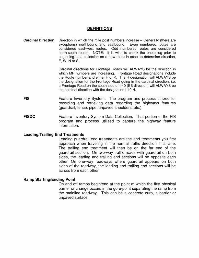
Cardinal Direction Direction in which the mile post numbers increase – Generally (there are
exceptions) northbound and eastbound. Even numbered routes are considered east-west routes. Odd numbered routes are considered north-south routes. NOTE: It is wise to check the photo log prior to beginning data collection on a new route in order to determine direction, E, W, N or S.
Cardinal directions for Frontage Roads will ALWAYS be the direction in
which MP numbers are increasing. Frontage Road designations include the Route number and either H or K. The H designation will ALWAYS be the designation for the Frontage Road going in the cardinal direction, i.e. a Frontage Road on the south side of I-40 (EB direction) will ALWAYS be the cardinal direction with the designation I-40 H.
FIS Feature Inventory System. The program and process utilized for
recording and retrieving data regarding the highways features (guardrail, fence, pipe, unpaved shoulders, etc.).
FISDC Feature Inventory System Data Collection. That portion of the FIS
program and process utilized to capture the highway feature information.
Leading/Trailing End Treatments Leading guardrail end treatments are the end treatments you first
approach when traveling in the normal traffic direction in a lane. The trailing end treatment will then be on the far end of the guardrail section. On two-way traffic roads with guardrail on both sides, the leading and trailing end sections will be opposite each other. On one-way roadways where guardrail appears on both sides of the roadway, the leading and trailing end sections will be across from each other
Ramp Starting/Ending Point
On and off ramps begin/end at the point at which the first physical barrier or change occurs in the gore-point separating the ramp from the mainline roadway. This can be a concrete curb, a barrier or unpaved surface.

ROADWAY CATEGORY FEATURES, SUB-FEATURES & ATTRIBUTES
I ROADWAY BARRIERS
1 GUARDRAIL Guardrail Panel Type Post Type Lineal Feet
Leading End Treatment
Trailing End Treatment
Galvanized W-Beam Panel Steel GPS ET 2000 ET 2000
Galvanized Thrie-Beam Panel Wood or ET 2000 Plus ET 2000 Plus
Corten W-Beam Panel Both Manual measure BCT BCT
Corten Thrie-Beam Panel Flared End Section Flared End Section
Other Parapet Connector Parapet Connector
W-Beam End Anchor
W-Beam End Anchor
SRT 350 SRT 350
FLEAT 350 FLEAT 350
SKT 350 SKT 350
BEST 350 BEST 350
Miscellaneous Miscellaneous
2 GUARDRAIL END
TREATMENTS Guardrail End
Type GPS Location
ET 2000
ET 2000 Plus
BCT
Flared End Section
Parapet Connector
W-Beam End Anchor
SRT 350
FLEAT 350
SKT 350
BEST 350
Miscellaneous

ROADWAY CATEGORY FEATURES, SUB-FEATURES & ATTRIBUTES
3 BARRIER END TREATMENT
End Treatment Type GPS Location
Number of Barrels/Bays/Cushions
(If Applicable)
Sand Barrels 5 - 15
Quad Guard
ADIEM II
REACT 350
Water filled Containers
GREAT
Sandwich
Smart Cushion
Misc
4 BARRIERS Barrier Type Lineal Feet No. of Cable Strands
Concrete GPS 1 - 4
Concrete w/Glare Screen or
Cable Manual measure
Chain Link Cable
Miscellaneous
5 HANDRAIL
(Non Bridge) Lineal Feet
GPS
or
Manual measurement
ROADWAY CATEGORY FEATURES, SUB-FEATURES & ATTRIBUTES
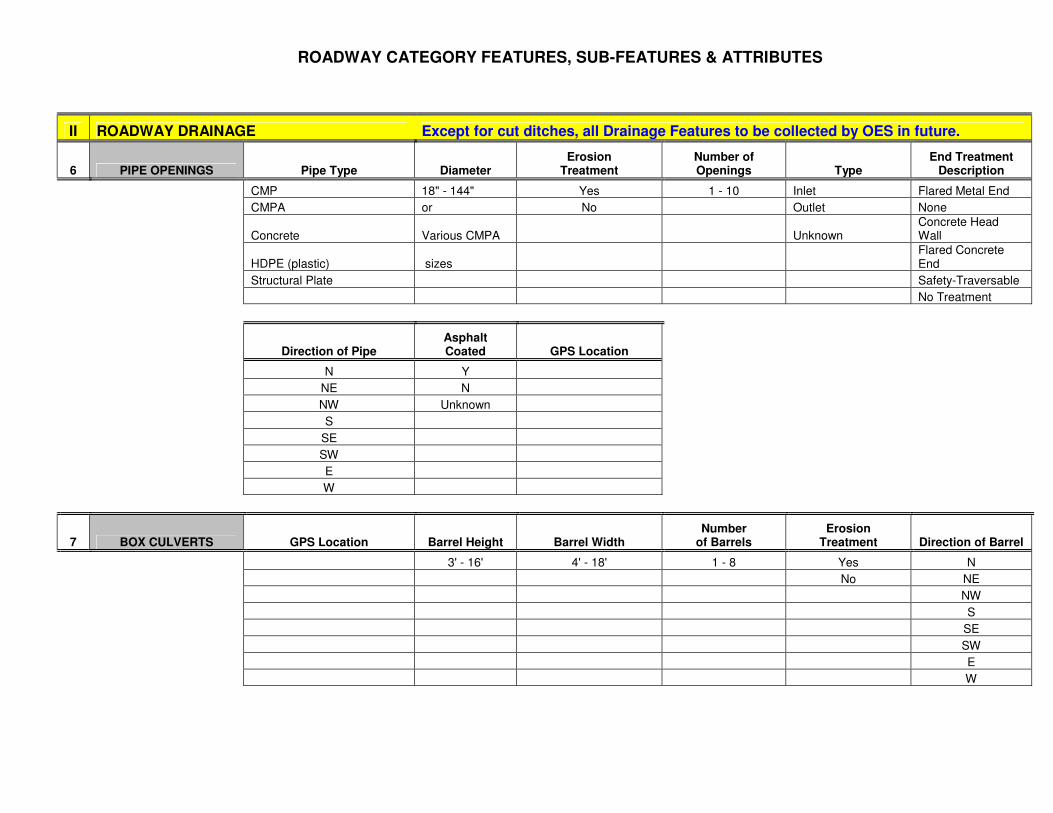
II ROADWAY DRAINAGE Except for cut ditches, all Drainage Features to be collected by OES in future.
6 PIPE OPENINGS Pipe Type Diameter Erosion
Treatment Number of Openings Type
End Treatment Description
CMP 18" - 144" Yes 1 - 10 Inlet Flared Metal End
CMPA or No Outlet None
Concrete Various CMPA Unknown Concrete Head Wall
HDPE (plastic) sizes Flared Concrete End
Structural Plate Safety-Traversable
No Treatment
Direction of Pipe Asphalt Coated GPS Location
N Y
NE N
NW Unknown
S
SE
SW
E
W
7 BOX CULVERTS GPS Location Barrel Height Barrel Width Number
of Barrels Erosion
Treatment Direction of Barrel
3' - 16' 4' - 18' 1 - 8 Yes N
No NE
NW
S
SE
SW
E
W

ROADWAY CATEGORY FEATURES, SUB-FEATURES & ATTRIBUTES
8 SPILLWAY Type of Spillway GPS Location
Single Inlet
Double Inlet
9 CATCH BASIN Catch Basin Type GPS Location Pipe Type Pipe Diameter Pipe Erosion
Treatment Number of
Pipe Openings
Type 1 Catch Basin CMP 18" - 144" Yes 1 - 10
This is a "Super Asset". Type 3 Catch Basin CMPA or No
It will allow for capturing Type 4 Catch Basin Concrete Various CMPA
multiple assets in one file. Type 5 Catch Basin HDPE (plastic) sizes
Drop Inlet Structural Plate
It will allow collection of Flush
pipe data from each wall Side Slope
of a catch basin (up to 4). Median Dike, Precast
Freeway Catch Basin
Concrete Half Barrier "F"
Misc.
Pipe End Treatment
Description Opening Type Direction of Pipe Asphalt
Coated Pipe
Flared Metal End Inlet N Y
None Outlet NE N
Concrete Head Wall Unknown NW Unknown
Flared Concrete End S
Safety-Traversable SE
No Treatment SW
E
W
10 SLOTTED DRAIN Diameter Lineal Feet
8" - 24" GPS
or
Manual measure

ROADWAY CATEGORY FEATURES, SUB-FEATURES & ATTRIBUTES
11 CURB Type of Curb Lineal Feet
Curb and Gutter GPS
Single Curb or
Embankment Curb Manual measure
Freeway Rolled Curb
12 DOWN DRAIN GPS Location Diameter Direction of Pipe
8" - 24" N
NE
NW
S
SE
SW
E
W
13 DIKES Lineal Feet
GPS
or
Manual measurement
14 CHANNEL Channel Type Depth Top Width Bottom Width Lineal Feet
Concrete Lined Manual measure Manual measure Manual measure GPS
Unlined or
Other Manual measure
15 DITCH Ditch Type Lineal Feet Paved
Crown Ditch GPS Yes
Grader Ditch or No

ROADWAY CATEGORY FEATURES, SUB-FEATURES & ATTRIBUTES
16 RETENTION /
DETENTION BASINS Acreage
GPS
or
Manual measure
17 BANK PROTECTION Bank Type Lineal Feet
Rip Rap GPS
Rail Bank or
Wired Rip Rap Manual measure
Gabion
Soil Cement
Other
18 PUMP STATIONS No. of Pumps driven by
Diesel Powered Generator
No. of Pumps driven by
Electric Utility power
No. of Pumps driven by Propane Powered
Generator
No. of Pumps driven by Natural
Gas Powered Generator GPS Location
See list for pump station info.
1 - 6 1 - 6 1 - 6 1 - 6
19 LEVEE Linear Feet
GPS
or
Manual measure
20 ROADWAY CUT DITCH Cut Ditch Type Miles to .01
Paved GPS
Unpaved or
Manual
Measure
ROADWAY CATEGORY FEATURES, SUB-FEATURES & ATTRIBUTES
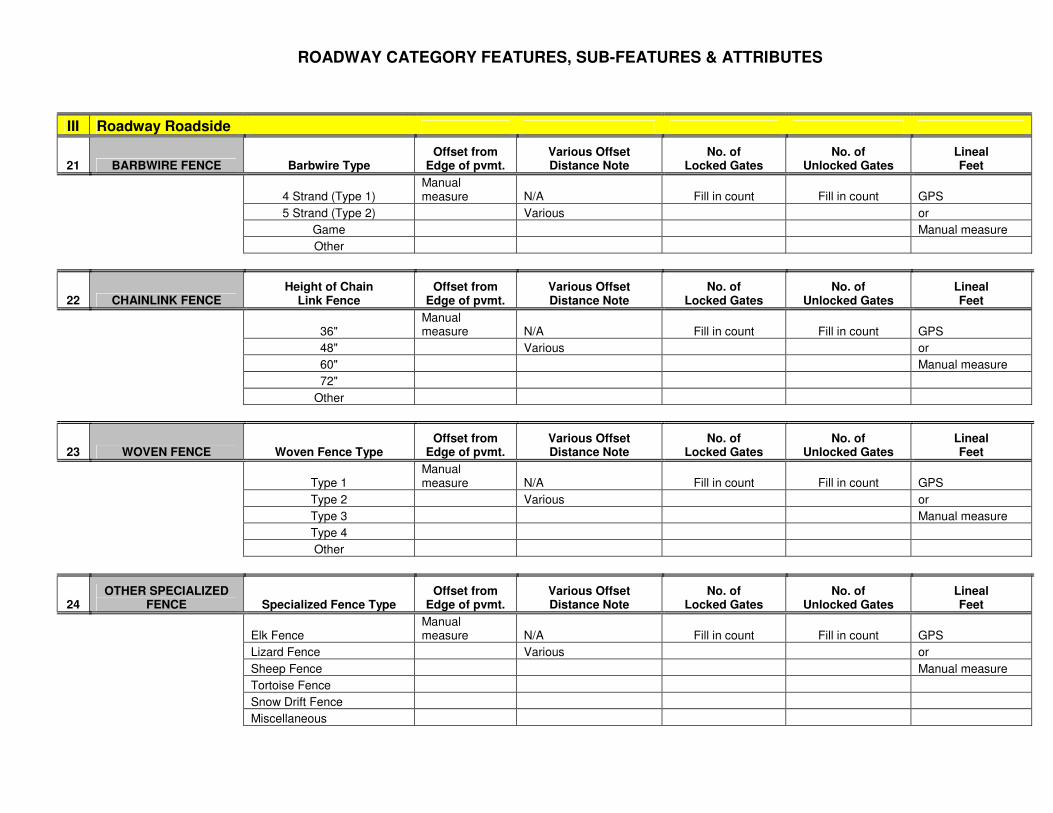
III Roadway Roadside
21 BARBWIRE FENCE Barbwire Type Offset from
Edge of pvmt. Various Offset Distance Note
No. of Locked Gates
No. of Unlocked Gates
Lineal Feet
4 Strand (Type 1) Manual measure N/A Fill in count Fill in count GPS
5 Strand (Type 2) Various or
Game Manual measure
Other
22 CHAINLINK FENCE Height of Chain
Link Fence Offset from
Edge of pvmt. Various Offset Distance Note
No. of Locked Gates
No. of Unlocked Gates
Lineal Feet
36" Manual measure N/A Fill in count Fill in count GPS
48" Various or
60" Manual measure
72"
Other
23 WOVEN FENCE Woven Fence Type Offset from
Edge of pvmt. Various Offset Distance Note
No. of Locked Gates
No. of Unlocked Gates
Lineal Feet
Type 1 Manual measure N/A Fill in count Fill in count GPS
Type 2 Various or
Type 3 Manual measure
Type 4
Other
24 OTHER SPECIALIZED
FENCE Specialized Fence Type Offset from
Edge of pvmt. Various Offset Distance Note
No. of Locked Gates
No. of Unlocked Gates
Lineal Feet
Elk Fence Manual measure N/A Fill in count Fill in count GPS
Lizard Fence Various or
Sheep Fence Manual measure
Tortoise Fence
Snow Drift Fence
Miscellaneous

ROADWAY CATEGORY FEATURES, SUB-FEATURES & ATTRIBUTES
25 CATTLE GUARD Cattle Guard Type GPS Location No. of Grills
Precast 2 - 10
Poured in Place
Other
26 REST AREA Rest Area Type GPS Location
Interstate
Non-Interstate
27 WALLS Wall Type Size in SF
Sound GPS AND
Retaining Measure
IV Roadway Shoulder
28 ROADWAY SHOULDER Shoulder Type
5 Ft. Shoulder Miles
Paved GPS
Unpaved or
Manual measure
V Roadway Surface
29 TURNOUT Type GPS Location Cattle Guard Type No. of Grills No. of
Locked Gates No. of
Unlocked Gates
Paved None 2 - 10 1 - 4 1 - 4
Unpaved Precast
Poured in Place
Other

ROADWAY CATEGORY FEATURES, SUB-FEATURES & ATTRIBUTES
30 CROSSOVER Type GPS Location
Paved
Unpaved
VI Roadway Miscellaneous
31 ROCKFALL
PROTECTION Protection Type Lineal Feet
Netting GPS
Cable Fence or
Miscellaneous Manual measure
32 SAFETY PULLOUT GPS Location
33 TRUCK ESCAPE RAMP GPS Location
34 SIDEWALKS Lineal Feet
GPS
or
Manual measure
35 ADA RAMPS GPS Location Count
1 - 2
36 CALL BOX GPS Location

ROADWAY CATEGORY FEATURES, SUB-FEATURES & ATTRIBUTES
37 TUNNEL Tunnel Type GPS Location
TYPE 1
TYPE 2
VII Roadway Structure
38 STRUCTURE GPS Location Structure
Name Structure No. Surface Type
Asphalt
Concrete

I N D E X
ROADWAY SUB-PROGRAM FEATURES
The features for the Roadway Sub-Program are broken down into seven Categories, each Category containing various, Features, Sub-Features and Attributes. Category I – Roadway Barriers Guardrail Galvanized W-Beam Panel ………………………………… I Corten W-Beam Panel……………………………………… I Galvanized Thrie-Beam Panel …………………………… 3 Corten Thrie-Beam Panel ………………………………… 3 Guardrail End Treatments Flared End Section ………………………………………… 4 Parapet Connector ………………………………………… 5 W-Beam End Anchor..……………………………………… 5 BEST-350…………………………………………………… 5 ET 2000……………………………………………………… 6 ET 2000 Plus/ET Plus ……………………………………… 7 BCT …………………………………………………………… 8 SRT-350 ……………………………………………………… 8 SKT-350 ……………………………………………………… 9 FLEAT-350 ……………………………………………………10
Barriers Concrete ………………………………………………… 11 Concrete with Glare Screen ………………………….. 12 Cable Barrier …………………………………………… 13 Chain Link Cable ………………………………………. 14
Barrier End Treatments QuadGuard ……………………………………………… 16 REACT-350..…………………………………………….. 17 GREAT …………………………………………………… 18 Sandwich ………………………………………………… 19 ADIEM II …………………………………………………. 20 Sand Barrels …………………………………………….. 20 Water filled Containers ………………………………… 21 Smart Cushion Impact Attenuator……………………… 22 .
Handrail Handrail ………………………………………………… 23

I N D E X
Category II – Roadway Drainage Pipe Openings Corrugated Metal Pipe (CMP)…………………. 25 Safety Traversable……………………………… 25 Corrugated Metal Pipe – Arched (CMPA)……. 26 Concrete Pipe……………………………………. 27 High Density Polyethylene (HDPE)……………. 28 Structural Plate…………………………………… 29 Box Culvert ………………………………………………………. 30 Spillway Single Inlet…………………………………………. 32 Double Inlet.......…………………………………… 33 Catch Basins Type 1 Catch Basin (Grate W/Curb Opening Inlet) 34 Type 3 Catch Basin (Curb Opening/Inlet Only)... 35 Type 4 Catch Basin...…………………………….. 35 Type 5 Catch Basin……………………………….. 35 Drop Inlet…………………………………………... 36 Flush Catch Basin…………………………………. 36 Median Side Slope Catch Basin…………………. 36 Median Dike, Pre Cast……………………………. 37 Freeway Catch Basin……………………………… 37 Concrete Half Barrier, Type F ……..……………. 38 Slotted Drain………………………………………………………. 39 Curb Curb & Gutter……………………………………….. 40 Single Curb..………………………………………... 41 Embankment Curb………………………………….. 41 Freeway Rolled Curb……………………………….. 42 Down Drain………………………………………………………….. 43 Dikes Type A……………………………………………….. 45 Type B Transverse Median Dike…………………. 45 Crown Dike………………………………………….. 45 Channel……………………………………………………………… 46

I N D E X
Ditches Crown Ditch………………………………………… 47 Grader Ditch……………………………………….. 48 Ditch…………………………………………………. 48 Roadway Cut Ditches …………………………………………… 49 Retention/Detention Basin……………………………………… 51 Bank Protection Gabion Baskets……………………………………. 52 Rip Rap……………………………………………… 53 Wired Rip Rap……………………………………… 53 Rail Bank Protection………………………………. 53 Soil Cement………………………………………… 54 Pump Stations…………………………………………………….. 55 Category III – Roadway Roadside Barbed Wire Fence 4 Strand (Type 1) ……………………………………… 57 5 Strand (Type 2) ……………………………………… 57 Game …………………………………………………… 57 Other Barbed Wire Fence…………………………….. 58 Chain Link Fence…………………………………………….. 59 Woven Fence Type 1 ………………………………………………….. 60 Type 2 ………………………………………………….. 60 Type 3 ………………………………………………….. 60 Type 4…………………………………………………… 60 Other……………………………………………………. 60 Other Specialized Fence Elk Fence……………………………………………….. 62
Sheep Fence ……………………………………………. 63 Tortoise Fence……………………………………………. 64 Snow Drift Fence………………………………………. 65 Miscellaneous Fence…………………………………… 65 Cattle Guard Poured in place ………………………………………… 66 Pre-cast ………………………………………….………. 67 Other……………………………………………………… 67

I N D E X
Rest Area Interstate/Non-Interstate ……………………………….. 68 Walls Sound Walls……………………………………………… 69 Retaining Walls………………………………………….. 70 Category IV – Roadway Shoulder 5’ Shoulder Miles – Paved & Unpaved ……………………………. 71 Category V– Roadway Surface Turnouts Turnouts – Paved or Unpaved…………………………. 73 Crossovers Crossovers – Paved or Unpaved………………………. 75 Category VII – Roadway Miscellaneous Rockfall Protection Netting…….…………….……………………………………… 76 Cable Fence ………...………………………………………… 77 Safety Pullout ………………………………………………………… 78 Truck Escape Ramp ………………………………………………… 79 Sidewalk ………………………………………………………………. 80 ADA Ramps ………………………………………………………….. 81 Call Box ……………………………………………………………… 82 Tunnel Type 1………………………………………………… 83 Type 2………………………………………………… 84 Category VII – Roadway Structures Structures…………………………………………………………… 85

1
CATEGORY: Roadway Barrier FEATURE: Guardrail SUBFEATURE W-Beam Galvanized Panels, Corten W-Beam Panels CONSTRUCTION STANDARD NO. C-10.03 – 06 MEASUREMENT INFORMATION: Guardrail measurement will start at the first guardrail post and end at the last post, except where bolted to a parapet wall, in which case it will begin/end at the point of the connection to the parapet wall. The first (several) post(s) will be part of the guardrail end treatment, however for measurement purposes, the rail portion of the end treatments will be considered as part of the guardrail panels. There are sections of W-Beam guardrail that transition to/from Thrie-Beam guardrail. In these instances, measurement of W-Beam guardrail panels will stop/start at the point of transition to/from Thrie-Beam guardrail. Measurement of guardrail starts and stops at each end of the barrier when sections of guardrail are interrupted by sections of barrier. MEASUREMENT LOCATION AND FREQUENCY: GPS readings shall be captured at the front face of each end of guardrail on tangent (straight) sections of guardrail. Multiple points must be recorded on curves at approximately 500' – 600’ intervals, more often as appropriate on tight radius curves (interchanges, etc). Start/end measurement at the first and last guardrail post (wood or steel) (Guardrail End Treatment) or connection point to barrier wall. In circumstances where GPS readings cannot be captured, (generally due to atmospheric conditions or obstructions) measurements shall be captured either by electronic measuring devices, measuring wheels or other measuring devices. When saving a record without a GPS reading, you will need to enter an accurate milepost and offset. MEASUREMENT UNIT:
Guardrail is a linear feature with the measurement in Lineal Feet. When multiple GPS readings are recorded, length will automatically be computed when the record is saved. Where physical measurement must be taken, enter the quantity, to the nearest foot, on the hand-held device. SUPER ASSET: Guardrail is one of the few assets that are designed as a Super Asset. This means that the collection and quantification of multiple assets, in one record, is possible. This represents a considerable time savings in data collection. Because a GPS point is collected at the beginning and end of a guardrail installation (where the Guardrail End Treatments are located) they share common GPS points. The Leading Guardrail End Treatment and the beginning of the guardrail share a common GPS point. The same applies to the Trailing Guardrail End Treatment, unless the guardrail transitions to Thrie Beam Guardrail. Collection of a single Guardrail End Treatment may also still be accomplished under the Guardrail End Treatment feature. Note: When searching the collection device for a guardrail end treatment that has been created under the Super Asset guardrail record, you must search under Guardrail End Treatment instead of Guardrail. GENERAL TAB INFO: You will also be asked to complete the following information on the General Tab: Post Type - Select from drop-down. Selections are Wood, Steel or Both. IMPORTANT – DO NOT CONSIDER THE STEEL POSTS THAT ARE PART OF THE END TREATMENT IN MAKING THE POST TYPE DETERMINATION. Post types, excluding the posts that are part of the end treatments should all be of one type. The selection of “Both” should be a rare occurrence.

2
CATEGORY: Roadway Barrier FEATURE: Guardrail SUBFEATURE W-Beam Galvanized Panels, Corten W-Beam Panels SUPER ASSET TAB: Allows the collection of Guardrail End Treatments within the Guardrail feature record. To collect Guardrail End Treatment, check appropriate box or boxes – Beg or End Guardrail End Treatment, then select the appropriate end treatment from the dropdown boxes. If guardrail transitions to a Thrie Beam Guardrail, or a different ramp on a TI, do not list a End Guardrail End Treatment, or vice-versa. IDENTIFICATION: Guardrail will usually fall within the following four types. Should you encounter guardrail in your data collection activities that does not conform to the following examples, collect the guardrail type as a “Miscellaneous” type and enter any distinguishing information in the “Notes” section of the “Common Tab” on the data collection device. In addition, take several photos, from different angles and email the photos, along with the route number and milepost to Bob Harris ([email protected]). Galvanized W-Beam Guardrail Corten W-Beam Guardrail

3
CATEGORY: Roadway Barrier FEATURE: Guardrail SUBFEATURE Galvanized Thrie-Beam Panels, Corten Thrie-Beam Panels CONSTRUCTION STANDARD NO. C-10.20 MEASUREMENT INFORMATION: There are sections of Thrie-Beam guardrail that transition to/from W-Beam guardrail. In these instances, measurement of Thrie-Beam guardrail panels will stop/start at the point of transition to/from W-Beam guardrail. Measurement of guardrail starts and stops at each end of the barrier when sections of guardrail are interrupted by sections of barrier. IDENTIFICATION: Galvanized Thrie-Beam
Corten Thrie-Beam

4
CATEGORY: Roadway Barrier FEATURE: Guardrail End Treatments SUBFEATURE Various End Treatments CONSTRUCTION STANDARD NO. http://www.azdot.gov/highways/RdwyEng/RoadwayDesign/mfrapp_drawings/index.asp See appropriate Drawing number(s) with each End Treatment Type. MEASUREMENT LOCATION AND FREQUENCY: GPS readings shall be captured center of the face of each end treatment, including both the leading and trailing end treatments. In circumstances where GPS readings cannot be captured, (generally due to atmospheric conditions or obstructions) the record shall be completed and saved without the GPS readings. When saving a record without a GPS reading, you will need to enter an accurate milepost and offset. MEASUREMENT UNIT: Guardrail End Treatments are a point feature. The measurement unit is each. The proper identification of the Guardrail End Treatment is very important for the quality of the inventory. GENERAL TAB INFO: No entry required for this feature. IDENTIFICATION: Identification of Guardrail End Treatments can be confusing. Some types are quite apparent while the difference in others can be relative minor. With some practice, the ability to correctly identify the various end treatments will become much easier. Should you encounter Guardrail End Treatments, in your data collection activities, which do not conform to the following examples, collect the end treatment as a “Miscellaneous” type and enter any distinguishing information in the “Notes” section of the “Common Tab” on the data collection device. In addition, take several photos, from different angles and email the photos, along with the route number and milepost to Bob Harris ([email protected]). FLARED END SECTION

5
CATEGORY: Roadway Barrier FEATURE: Guardrail End Treatments SUBFEATURE Various End Treatments PARAPET CONNECTOR
W-BEAM END ANCHOR CONSTRUCTION STANDARD NO. C-10.08
BEST 350 CONSTRUCTION STANDARD NO. http://www.azdot.gov/highways/RdwyEng/RoadwayDesign/mfrapp_drawings/index.asp See appropriate Drawing number(s) with each End Treatment Type.
Note top view of impact head Note how anchor cable attaches to rail.

6
CATEGORY: Roadway Barrier FEATURE: Guardrail End Treatments SUBFEATURE Various End Treatments - Continued CONSTRUCTION STANDARD NO. http://www.azdot.gov/highways/RdwyEng/RoadwayDesign/mfrapp_drawings/index.asp See appropriate Drawing number(s) with each End Treatment Type. BEST 350 (CONTINUED)
Traffic Side – Note openings Note unique, short profile of Back view behind impact face impact head ET 2000 Drawing SS 241
Note narrow throat to flatten W-Beam panel
Note solid panel on traffic side of impact head
Note cable connection to
guardrail panel.
Back Side
Traffic Side

7
CATEGORY: Roadway Barrier FEATURE: Guardrail End Treatments SUBFEATURE Various End Treatments - Continued CONSTRUCTION STANDARD NO. http://www.azdot.gov/highways/RdwyEng/RoadwayDesign/mfrapp_drawings/index.asp See appropriate Drawing number(s) with each End Treatment Type. ET 2000 Plus or ET PLUS Drawing SS 171
Note rectangular
shaped impact head as
opposed to the square head
on the ET 2000 and SKT
350
Note single, narrow opening through
impact head directs panel out BACK of impact head
Back view
Traffic Side
Note cable attachment to guardrail panel is the same as the ET 2000

8
CATEGORY: Roadway Barrier FEATURE: Guardrail End Treatments SUBFEATURE Various End Treatments - Continued CONSTRUCTION STANDARD NO. http://www.azdot.gov/highways/RdwyEng/RoadwayDesign/mfrapp_drawings/index.asp See appropriate Drawing number(s) with each End Treatment Type. BCT (Breakaway Cable Terminal) Construction (C-Std) Standard C-10.17 (1991 Edition)
SRT 350 (Slotted Rail Terminal) Drawing SS 355, SS 444, SS 428
Note that the “Buffered End” does not attach to the guardrail panel in the same manner as the BCT. Also note the manner of attachment of the cable to the rail.
Note how the “Buffered End” attaches to the guardrail panel.

9
CATEGORY: Roadway Barrier FEATURE: Guardrail End Treatments SUBFEATURE Various End Treatments - Continued CONSTRUCTION STANDARD NO. http://www.azdot.gov/highways/RdwyEng/RoadwayDesign/mfrapp_drawings/index.asp See appropriate Drawing number(s) with each End Treatment Type.
SKT 350 (Sequential Kinking Terminal) Drawing SKT-W-2US-AZ
Note square face and shape of Traffic Side – Note large openings in impact head overall impact head
Traffic Side – Note small slots in rail Back Side – Note large openings in impact head
Note bolt anchor detail – Rear & Front

10
CATEGORY: Roadway Barrier FEATURE: Guardrail End Treatments SUBFEATURE Various End Treatments - Continued CONSTRUCTION STANDARD NO. http://www.azdot.gov/highways/RdwyEng/RoadwayDesign/mfrapp_drawings/index.asp See appropriate Drawing number(s) with each End Treatment Type. FLEAT 350 (Flared Energy Absorbing Terminal) Drawing No. FLT-W-US-AZ
Note how impact head is offset to the Note narrow openings behind face of impact traffic side head. Also note that upon impact, guardrail
ribbon will be forced out of the impact head on the TRAFFIC side
View from traffic side. Note short Back Side overall length of impact head

11
CATEGORY: Roadway Barrier FEATURE: Barrier SUBFEATURE Various CONSTRUCTION STANDARD NO. C-10.40 - 77 MEASUREMENT INFORMATION: Barrier measurement will start at the leading end of the barrier and end at the trailing end of barrier. MEASUREMENT LOCATION AND FREQUENCY: GPS readings shall be captured at each end of barrier on tangent (straight) sections of barrier. Multiple points must be recorded on long sweeping curves at approximately 400' – 600’ (or as appropriate) intervals, more often on tighter radius curves and interchanges. Start/end measurement at the leading and trailing end of the barrier. In circumstances where GPS readings cannot be captured, (generally due to atmospheric conditions or obstructions) measurements shall be captured either by electronic measuring devices, measuring wheels or other measuring devices. When saving a record without a GPS reading, you will need to enter an accurate milepost and offset. MEASUREMENT UNIT: Concrete Barrier is a linear feature with the measurement in Lineal Feet. When multiple GPS readings are recorded, length will automatically be computed when the record is saved. Where physical measurement must be taken, enter the quantity, to the nearest foot, on the hand-held device. GENERAL TAB INFO: No entry required for this feature. IDENTIFICATION: The following photos will help in identifying the various types of barriers. CONCRETE BARRIER

12
CATEGORY: Roadway Barrier FEATURE: Barrier SUBFEATURE Various CONCRETE BARRIER (continued) Concrete Barrier is often found separating freeway lanes going in opposite directions, but can also be found separating roadways going in the same direction. Where concrete barrier separates roadways going in opposite directions (medians), record the feature in the cardinal direction. Be careful not to overlook a barrier feature because it looks like something else. Note on below, left – concrete barrier AND chainlink fence (2 separate features) and right – concrete barrier AND sound wall.
CONCRETE BARRIER WITH GLARE SCREEN CONSTRUCTION STANDARD NO. C-10.42 Concrete Barrier with Glare Screen is a feature that is usually found on freeways, separating traffic traveling in opposing directions. Where concrete barrier with glare screen separates roadways going in opposite directions (medians), record the feature in the cardinal direction. The glare screen serves two purposes – reducing the glare of approaching headlights and limiting visual distractions.

13
CATEGORY: Roadway Barrier FEATURE: Barrier SUBFEATURE Cable Barrier CABLE BARRIER Cable Barrier is a feature that is often times found separating traffic traveling in opposing directions on freeways, much the same as concrete barrier and concrete barrier with glare screen, though it can also be found separating roadways (such as frontage roads) traveling in the same direction. It may also be found as a single strand barrier limiting access to roadways. Cable Barrier may consist of 1, 2, 3 or 4 cable strands.

14
CATEGORY: Roadway Barrier FEATURE: Barrier SUBFEATURE Cable Barrier CABLE BARRIER (continued)
Single Strand Cable Barrier
CHAIN LINK CABLE BARRIER CONSTRUCTION STANDARD NO. - Various The chain link cable barrier feature is often found in locations where its’ purpose is to prevent vehicles from entering a location where there is a sudden change (drop) in elevation. It may also be found at a “T” intersection, preventing vehicles from entering an adjacent roadway, as well as other locations. Where this barrier exists in a median, protecting grade changes, collect the feature in the direction of the traffic flow for which it provides protection. See note/example below. EB I-10 WB I-10
This Chain Link Cable Barrier is protecting traffic traveling in the EB direction; therefore it would be collected as an EB median feature.

15
CATEGORY: Roadway Barrier FEATURE: Barrier SUBFEATURE Chain Link Cable Barrier (continued)
END BARRIER SECTION

16
CATEGORY: Roadway Barrier FEATURE: Barrier End Treatments SUBFEATURE Various End Treatments CONSTRUCTION STANDARD NO. http://www.azdot.gov/highways/RdwyEng/RoadwayDesign/mfrapp_drawings/index.asp See appropriate Drawing number(s) with each End Treatment Type. MEASUREMENT LOCATION AND FREQUENCY: GPS readings shall be captured center of the face of each Barrier End Treatment. In circumstances where GPS readings cannot be captured, (generally due to atmospheric conditions or obstructions) the record shall be completed and saved without the GPS readings. When saving a record without a GPS reading, you will need to enter an accurate milepost and offset. MEASUREMENT UNIT: Barrier End Treatments are a point feature. The measurement unit is each. GENERAL TAB INFO: You will also be asked to complete the following information on the General Tab: No. of Barrels/Bays/Cushions - Select from drop-down as appropriate IDENTIFICATION: Identification of Barrier End Treatments should be less confusing than the guardrail end treatments. There are fewer types and the differences between Barrier End Treatments are great. Should you encounter Barrier End Treatments during your data collection activities that do not conform to the following examples, collect the end treatment as a “Miscellaneous” type and enter any distinguishing information in the “Notes” section of the “Common Tab” on the data collection device. In addition, take several photos, from different angles and email the photos, along with the route number and milepost to Bob Harris ([email protected]). QUAD GUARD Construction Drawing http://www.energyabsorption.com/products/approvals/permanent_appr_pdf/eas_QuadGuard_appr.pdf The Quad Guard Barrier End Treatment is quite easy to identify, although its’ overall length, width and shape may be different from location to location, as seen below. Note that the name of the end treatment is molded into the crash cushion cartridge
17
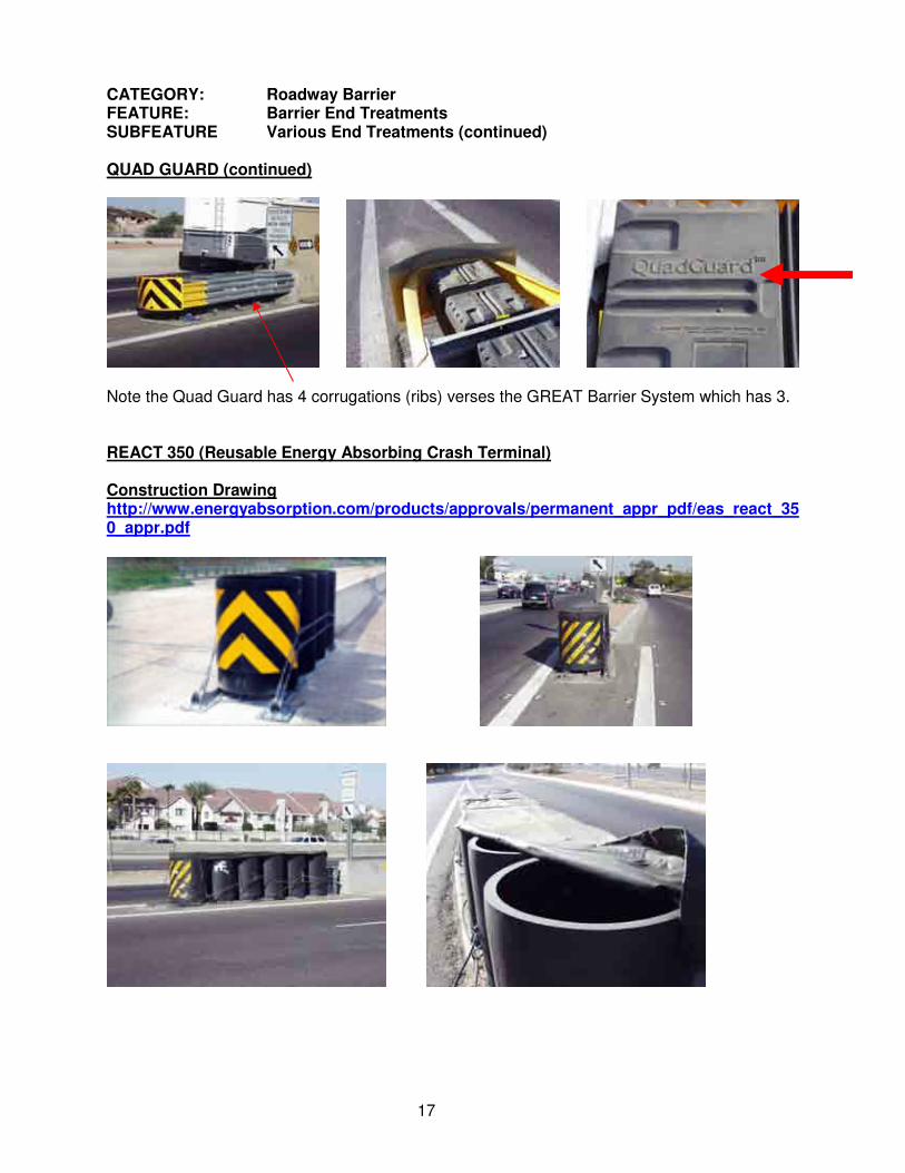
CATEGORY: Roadway Barrier FEATURE: Barrier End Treatments SUBFEATURE Various End Treatments (continued) QUAD GUARD (continued)
Note the Quad Guard has 4 corrugations (ribs) verses the GREAT Barrier System which has 3. REACT 350 (Reusable Energy Absorbing Crash Terminal) Construction Drawing http://www.energyabsorption.com/products/approvals/permanent_appr_pdf/eas_react_350_appr.pdf

18
CATEGORY: Roadway Barrier FEATURE: Barrier End Treatments SUBFEATURE Various End Treatments (continued) REACT 350 (Reusable Energy Absorbing Crash Terminal) (continued)
This portion of the feature is located This stamp, “REACT 350”, is located on at the back of the feature. previous photo. G-R-E-A-T Barrier System
Note that the G-R-E-A-T System has only 3 corrugations (ribs), though similar in appearance (at first glance) to the Quad Guard. This system is not one which has seen a great deal of use in Arizona, although they have been used occasionally. If you locate one of these features, please provide the information and notification listed in the Identification paragraph on the first page of the Barrier End Treatment section.

19
CATEGORY: Roadway Barrier FEATURE: Barrier End Treatments SUBFEATURE Various End Treatments (continued) SANDWICH HEX-FOAM SYSTEM
The SANDWICH Hex-Foam System is another system that has not seen much use in Arizona. As with the GREAT System, if you locate one of these features, please provide the information and notification listed in the Identification paragraph on the first page of the Barrier End Treatment section.

20
CATEGORY: Roadway Barrier FEATURE: Barrier End Treatments SUBFEATURE Various End Treatments (continued) ADIEM II BARRIER END TREATMENT Construction Drawing: http://www.highwayguardrail.com/products/adiem.html
SAND BARREL BARRIER END TREATMENT There are various sets of standard drawings for sand barrels, depending on the manufacturer.
In the photos above, Sand Barrels appear on both sides of a median obstruction. Each feature will be captured in the direction of approach – in this case, 1 Feature of 12 sand barrels in the eastbound direction, median side and 1 Feature of 12 sand barrels in the westbound direction, median side.

21
CATEGORY: Roadway Barrier FEATURE: Barrier End Treatments SUBFEATURE Various End Treatments (continued) SAND BARREL BARRIER END TREATMENT (continued)
The photo above shows a typical sand barrel installation for an obstruction on the right side of the road. Typical installations usually include 12 – 15 sand barrels. WATER-FILLED BARRIER END TREATMENTS
The above pictured water-filled barriers are located on I-17 at the Daisy Mountain and Anthem interchanges. These are only one type of water-filled containers that you may find on the Arizona highway system. Should you encounter other types of water-filled barrier end treatments during your data collection activities, record them under this feature and take several photos, from different angles and email the photos, along with the route number and milepost to Bob Harris ([email protected]).

22
CATEGORY: Roadway Barrier FEATURE: Barrier End Treatments SUBFEATURE Various End Treatments (continued) SMART CUSHION IMPACT ATTENUATOR CONSTRUCTION STANDARD NO. http://www.workareaprotection.com/attenuator.htm IDENTIFICATION: At first glance, the Smart Cushion Impact Attenuator looks very similar to the Quad Guard End Treatment. The immediate difference you will notice is the absence of cushions inside the crash attenuator. In lieu of cushions, the Smart Cushion Attenuator utilizes hydraulics to absorb the crash energy.

23
CATEGORY: Roadway Barrier FEATURE: Handrail SUBFEATURE Handrail CONSTRUCTION STANDARD NO. No construction standards are provided due to the variety of types that may be found on the highway system. MEASUREMENT INFORMATION: Handrail measurement will start at the first post and end at the last post. Handrail is most frequently found adjacent to drainage structures, but may be found as barriers between traffic and pedestrians and on freeways on elevated planting beds. Handrail on structures (bridges) is not included in this feature. MEASUREMENT LOCATION AND FREQUENCY: GPS readings shall be captured at the front face of each end of Handrail on tangent (straight) sections of handrail. Multiple points should be recorded on curves or at directional changes in the handrail. In circumstances where GPS readings cannot be captured, (generally due to atmospheric conditions or obstructions) measurements shall be captured either by electronic measuring devices, measuring wheels or other measuring devices. When saving a record without a GPS reading, you will need to enter an accurate milepost and offset. GENERAL TAB INFO: No additional information required. MEASUREMENT UNIT: Handrail is a linear feature with the measurement in Lineal Feet. When multiple GPS readings are recorded, length will automatically be computed when the record is saved. Where physical measurement must be taken, enter the quantity, to the nearest foot, on the hand-held device. IDENTIFICATION:
Note on this and the following page that handrail type and location can vary considerably.

24
CATEGORY: Roadway Barrier FEATURE: Handrail SUBFEATURE Handrail (continued)

25
CATEGORY: Roadway Drainage FEATURE: Pipe Openings SUBFEATURE CMP (Corrugated Metal Pipe) CONSTRUCTION STANDARD NO. C- 13.10 MEASUREMENT LOCATION AND FREQUENCY: GPS readings shall be captured at the top center of each end of the CMP. In cases where there are multiple down CMP’s at the same location, capture the GPS reading at the center of the group of CMP’s. In circumstances where GPS readings cannot be captured, (generally due to atmospheric conditions or obstructions) the record shall be completed and saved without the GPS readings. When saving a record without a GPS reading, you will need to enter an accurate milepost and offset. MEASUREMENT UNIT: CMP’s are point features. The measurement unit is each opening. GENERAL TAB INFO: You will also be asked to complete the following information on the General Tab: Diameter – Select from drop-down – measure side to side diameter if silted-in. Erosion Treatment – Select from drop-down Number of Openings – Select from drop-down
Inlet End Treatment – Select from drop-down Outlet End Treatment - Select from drop-down IDENTIFICATION: Identification of CMP’s is fairly simple. They also bear some similarities to CMPA (Corrugated Metal Pipe – Arched) and Structural Plate large pipe which comes in pieces which must be bolted together to form the pipe). The end treatment of the pipe must also be identified and recorded. Some examples are provided below.
CMP with Flared Metal End Section
Safety Traversable End Section

26
CATEGORY: Roadway Drainage FEATURE: Pipe Openings SUBFEATURE CMPA (Corrugated Metal Pipe – Arched) CONSTRUCTION STANDARD NO. Installation same as CMP – C-13.10 IDENTIFICATION: CMPA’s are similar to CMP’s, except they have more of an oblong shape instead of a round shape. CMPA’s are generally utilized in situations where there is minimal cover between the top of the pipe and the finished grade of the roadway.
Pictured above are CMPA’s with Flared Metal End Sections. See the CMP page for identification of other end section types.

27
CATEGORY: Roadway Drainage FEATURE: Pipe Openings SUBFEATURE Concrete Pipe CONSTRUCTION STANDARD NO. None IDENTIFICATION: Concrete pipe is sometimes referred to as Rolled Concrete Pipe
The photo at right shows concrete pipe with a concrete headwall.
Large diameter concrete pipe

28
CATEGORY: Roadway Drainage FEATURE: Pipe Openings SUBFEATURE HDPE (plastic) Pipe (High Density Polyethylene) CONSTRUCTION STANDARD NO. None IDENTIFICATION: HDPE Pipe often include a concrete headwall or they may be found in the wall of a catch basin

29
CATEGORY: Roadway Drainage FEATURE: Pipe Openings SUBFEATURE Structural Plate Pipe CONSTRUCTION STANDARD NO. Various IDENTIFICATION: Structural Plate Pipe is usually found in the larger diameter pipe, six feet and larger. The pipe is formed by bolting multiple sections together to form the pipe.
Note bolts joining sections. Note joints where sections are joined.

30
CATEGORY: Roadway Drainage FEATURE: Box Culverts (CBC) SUBFEATURE Box Culverts CONSTRUCTION STANDARD NO. Various MEASUREMENT LOCATION AND FREQUENCY: GPS readings shall be captured at the top center of each end of the Box Culvert. In cases where there are multiple down Box Culverts at the same location, capture the GPS reading at the center of the group of Box Culverts. Each end of a Box Culvert or Multi-Barreled Box Culvert is to be captured as separate records. In circumstances where GPS readings cannot be captured, (generally due to atmospheric conditions or obstructions) the record shall be completed and saved without the GPS readings. When saving a record without a GPS reading, you will need to enter an accurate milepost and offset. MEASUREMENT UNIT: Box Culverts are point features. The measurement unit is each opening. GENERAL TAB INFO: You will also be asked to complete the following information on the General Tab: Height – Select from drop-down (may have remove silt to measure) Width - Select from drop-down Erosion Treatment – Select from drop-down Number of Openings – Select from drop-down
Inlet End Treatment – Select from drop-down IDENTIFICATION:

31
CATEGORY: Roadway Drainage FEATURE: Box Culverts (CBC) SUBFEATURE Box Culverts (Continued)
Example of one type of erosion control – rocks set in the concrete apron to decrease the velocity of water.

32
CATEGORY: Roadway Drainage FEATURE: Spillway SUBFEATURE Various Spillway Types CONSTRUCTION STANDARD NO. C- 4.10 MEASUREMENT LOCATION AND FREQUENCY: GPS readings shall be captured at the top center of each Spillway. In cases where there are multiple Spillways at the same location, capture the GPS reading at the center of the group of Spillways. In circumstances where GPS readings cannot be captured, (generally due to atmospheric conditions or obstructions) the record shall be completed and saved without the GPS readings. When saving a record without a GPS reading, you will need to enter an accurate milepost and offset. MEASUREMENT UNIT: Spillways are point features. The measurement unit is each. GENERAL TAB INFO: No entry required IDENTIFICATION: SINGLE INLET SPILLWAY

33
CATEGORY: Roadway Drainage FEATURE: Spillway SUBFEATURE Various Spillway Types CONSTRUCTION STANDARD NO. C- 4.10 IDENTIFICATION: SINGLE INLET SPILLWAY (continued)
DOUBLE INLET SPILLWAY

34
CATEGORY: Roadway Drainage FEATURE: Catch Basin SUBFEATURE Various Catch Basins CONSTRUCTION STANDARD NO. - VARIOUS MEASUREMENT LOCATION AND FREQUENCY: GPS readings shall be captured center of the Catch Basin(s) at the curb line. In cases where there are multiple catch basin grills at the same location, capture the GPS reading at the center of the multiple grills. In circumstances where GPS readings cannot be captured, (generally due to atmospheric conditions or obstructions) the record shall be completed and saved without the GPS readings. When saving a record without a GPS reading, you will need to enter an accurate milepost and offset. MEASUREMENT UNIT: Catch basins are a point feature. The measurement unit is each. GENERAL TAB INFO: Enter count from drop-down box as appropriate. IDENTIFICATION: Identification of catch basins is somewhat confusing. There are some 10 types we will attempt to identify and record. The number is what presents the challenge. There are, in some cases, subtle differences, while in other cases the differences are significant. Please refer the specified Construction Standard to assist in identification if the photos are inadequate. Catch Basin types that do not conform to the listed types shall be recorded as a Miscellaneous type. IDENTIFICATION: CONSTRUCTION STANDARD - VARIOUS TYPE 1 CATCH BASIN (Grate With Curb Opening) CONSTRUCTION STANDARD NO. C-15.10
Two different types of grated curb openings are shown above. The determination of whether there are one, two or more catch basins is NOT determined by the number of grills, but whether they empty into the same basin. Regardless of the number of grills or their separation, if they empty into a common basin they are one feature.

35
CATEGORY: Roadway Drainage FEATURE: Catch Basin SUBFEATURE Various Catch Basins CONSTRUCTION STANDARD NO. - VARIOUS IDENTIFICATION: TYPE 3 CATCH BASIN (Curb Opening/Inlet Only) CONSTRUCTION STANDARD C-15.20
TYPE 4 CATCH BASIN CONSTRUCTION STANDARD NO. C-15.30
TYPE 5 CATCH BASIN CONSTRUCTION STANDARD NO. C-15.40

36
CATEGORY: Roadway Drainage FEATURE: Catch Basin SUBFEATURE Various IDENTIFICATION: DROP INLET CATCH BASIN CONSTRUCTION STANDARD NO. C-15.75
FLUSH CATCH BASIN CONSTRUCTION STANDARD NO. C- 15.80
This feature may be found in the medians as well as on the side of the road. It may or may not have the rip rap surrounding the apron. MEDIAN SIDE SLOPE CATCH BASIN CONSTRUCTION STANDARD NO. C- 15.81

37
CATEGORY: Roadway Drainage FEATURE: Catch Basin SUBFEATURE Various IDENTIFICATION: MEDIAN DIKE PRECAST CATCH BASIN CONSTRUCTION STANDARD NO. C- 15.90
This feature is generally associated with freeway Note 2 inlets median crossovers or high points in the median. It may have one or two inlets. Where two inlets empty into the same catch basin, they are counted as one catch basin and the GPS location is recorded between the two inlet grates.
FREEWAY CATCH BASIN CONSTRUCTION STANDARD NO. C- 15.91

38
CATEGORY: Roadway Drainage FEATURE: Catch Basin SUBFEATURE Various IDENTIFICATION: CONCRETE HALF BARRIER CONSTRUCTION STANDARD NO. C- 15.92
May be found in conjunction with Slotted Drain Pipe. These are two separate features.
End Catch Basin Section

39
CATEGORY: Roadway Drainage FEATURE: Slotted Drain Pipe SUBFEATURE Slotted Drain Pipe CONSTRUCTION STANDARD NO. C- 13.60 MEASUREMENT INFORMATION: Slotted Drain Pipe measurement will start at the beginning of the slotted and terminate at the end of the slotted drain. MEASUREMENT LOCATION AND FREQUENCY: GPS readings shall be captured at each end of the slotted drains on tangent (straight) sections of the feature. Multiple points must be recorded on curves at appropriate intervals. Generally, the runs of slotted drain are relatively short, 5’ – 100’. In circumstances where GPS readings cannot be captured, (generally due to atmospheric conditions or obstructions) measurements shall be captured either by electronic measuring devices, measuring wheels or other measuring devices. When saving a record without a GPS reading, you will need to enter an accurate milepost and offset. MEASUREMENT UNIT: Lineal Feet. When multiple GPS readings are recorded, length will automatically be computed when the record is saved. Where physical measurement must be taken, enter the quantity, to the nearest foot, on the General Tab of the hand-held device. GENERAL TAB INFO: You will also be asked to complete the following information on the General Tab: Slotted Drain pipe diameter – select from drop-down box. IDENTIFICATION:
Slotted Drain Pipe may be found adjacent to other drainage features, such as Freeway Catch Basins or Concrete Half Barrier Catch Basins, or adjacent to concrete barriers on the freeway.
End Slotted Drain Section

40

41
CATEGORY: Roadway Drainage FEATURE: Curb SUBFEATURE Curb and Gutter CONSTRUCTION STANDARD NO. C- 5.10 MEASUREMENT INFORMATION: Curb measurement will start at the beginning of the curb and gutter and terminate at the end of the curb and gutter. MEASUREMENT LOCATION AND FREQUENCY: GPS readings shall be captured at the front face of each end of curb and gutter on tangent (straight) sections of the feature. Multiple points must be recorded on curves at appropriate intervals. In circumstances where GPS readings cannot be captured, (generally due to atmospheric conditions or obstructions) measurements shall be captured either by electronic measuring devices, measuring wheels or other measuring devices. When saving a record without a GPS reading, you will need to enter an accurate milepost and offset. MEASUREMENT UNIT: Lineal Feet. When multiple GPS readings are recorded, length will automatically be computed when the record is saved. Where physical measurement must be taken, enter the quantity, to the nearest foot, on the General Tab of the hand-held device. GENERAL TAB INFO: No entry required when GPS data is collected. IDENTIFICATION: Curb and gutter may be present either with or without sidewalk.
42
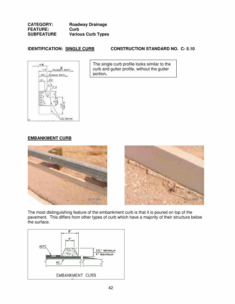
CATEGORY: Roadway Drainage FEATURE: Curb SUBFEATURE Various Curb Types IDENTIFICATION: SINGLE CURB CONSTRUCTION STANDARD NO. C- 5.10
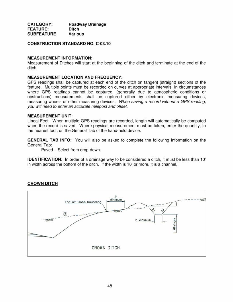
EMBANKMENT CURB
The most distinguishing feature of the embankment curb is that it is poured on top of the pavement. This differs from other types of curb which have a majority of their structure below the surface.
The single curb profile looks similar to the curb and gutter profile, without the gutter portion.

43
CATEGORY: Roadway Drainage FEATURE: Curb SUBFEATURE Freeway Rolled Curb CONSTRUCTION STANDARD NO. C- 5.10
Freeway rolled curb is often seen with the freeway catch basin and slotted drains as pictured in the bottom two photos.

44
CATEGORY: Roadway Drainage FEATURE: Down Drain SUBFEATURE Down Drain CONSTRUCTION STANDARD NO. C- 04.20 MEASUREMENT LOCATION AND FREQUENCY: GPS readings shall be captured center of the Down drain at the curb line. In cases where there are multiple down drain grills at the same location, capture the GPS reading at the center of the multiple grills. In circumstances where GPS readings cannot be captured, (generally due to atmospheric conditions or obstructions) the record shall be completed and saved without the GPS readings. When saving a record without a GPS reading, you will need to enter an accurate milepost and offset. MEASUREMENT UNIT: Down Drains are point features. The measurement unit is each. GENERAL TAB INFO: No entry required when GPS data is collected. IDENTIFICATION: Identification of Down Drains is much easier than identification of catch basins. The down drain consists of a curb inlet with a pipe carrying water from the inlet to the toe of the fill slope. The inlet of the pipe includes a “domed” welded steel rebar cap to prevent trash and debris from entering the drainage. Per the C-Standard, the pipe is set vertically with a lateral pipe which angles down the slope (refer to C-Std).

45
CATEGORY: Roadway Drainage FEATURE: Down Drain SUBFEATURE Down Drain (continued)
Please note that the photo on the above right shows the outlet for the down drain. This is considered part of the down drain feature and is not captured as a separate feature.
In the photos below you will note a variation from the standard. Instead of a vertical pipe inlet, the inlet is horizontal. For recording purposes these will be collected as catch basins.
End Down Drain Section

46
CATEGORY: Roadway Drainage FEATURE: Dikes SUBFEATURE Dikes CONSTRUCTION STANDARD NO. C-13.10 MEASUREMENT INFORMATION: Dike measurement will start at the beginning point of the Dike and terminate at the end of the Dike. In cases of Transverse Median Dikes, collect them in the Cardinal Direction. MEASUREMENT LOCATION AND FREQUENCY: GPS readings shall be captured at each end of the Dike on tangent (straight) sections of the feature. Multiple points must be recorded on curves at appropriate intervals. In circumstances where GPS readings cannot be captured, (generally due to atmospheric conditions or obstructions) measurements shall be captured either by electronic measuring devices, measuring wheels or other measuring devices. When saving a record without a GPS reading, you will need to enter an accurate milepost and offset. MEASUREMENT UNIT: Lineal Feet. When multiple GPS readings are recorded, length will automatically be computed when the record is saved. Where physical measurement must be taken, enter the quantity, to the nearest foot, on the General Tab of the hand-held device. GENERAL TAB INFO: No entry required when GPS data is collected IDENTIFICATION: All of the various types of Dikes are recorded under this feature.
Note that Dikes can run parallel or perpendicular to the roadway. Note that Median Dike Precast Catch Basins will often be found where the Transverse Median Dike is located.

47
CATEGORY: Roadway Drainage FEATURE: Channel SUBFEATURE Channel CONSTRUCTION STANDARD NO. C-03.10 MEASUREMENT INFORMATION: Channel measurement will start at the beginning of the Channel at the end of the Channel. MEASUREMENT LOCATION AND FREQUENCY: GPS readings shall be captured at each end of the Channel on tangent (straight) sections of the feature. Multiple points must be recorded on curves at appropriate intervals. In circumstances where GPS readings cannot be captured, (generally due to atmospheric conditions or obstructions) measurements shall be captured either by electronic measuring devices, measuring wheels or other measuring devices. When saving a record without a GPS reading, you will need to enter an accurate milepost and offset. MEASUREMENT UNIT: Lineal Feet. When multiple GPS readings are recorded, length will automatically be computed when the record is saved. Where physical measurement must be taken, enter the quantity, to the nearest foot, on the General Tab of the hand-held device. GENERAL TAB INFO: You will also be asked to complete the following information on the General Tab: Depth – Manual measurement. Top Width – Manual measurement. Bottom Width - Manual measurement. IDENTIFICATION: In order of a drainage way to be considered a channel, it must be a minimum of 10’ in width across the bottom of the channel. If the width is less than10’, it is a ditch. Channels may be either lined with concrete, other materials or unlined.
Concrete Lined Unlined Unlined
48
CATEGORY: Roadway Drainage FEATURE: Ditch SUBFEATURE Various CONSTRUCTION STANDARD NO. C-03.10 MEASUREMENT INFORMATION: Measurement of Ditches will start at the beginning of the ditch and terminate at the end of the ditch. MEASUREMENT LOCATION AND FREQUENCY: GPS readings shall be captured at each end of the ditch on tangent (straight) sections of the feature. Multiple points must be recorded on curves at appropriate intervals. In circumstances where GPS readings cannot be captured, (generally due to atmospheric conditions or obstructions) measurements shall be captured either by electronic measuring devices, measuring wheels or other measuring devices. When saving a record without a GPS reading, you will need to enter an accurate milepost and offset. MEASUREMENT UNIT: Lineal Feet. When multiple GPS readings are recorded, length will automatically be computed when the record is saved. Where physical measurement must be taken, enter the quantity, to the nearest foot, on the General Tab of the hand-held device. GENERAL TAB INFO: You will also be asked to complete the following information on the General Tab: Paved – Select from drop-down. IDENTIFICATION: In order of a drainage way to be considered a ditch, it must be less than 10’ in width across the bottom of the ditch. If the width is 10’ or more, it is a channel. CROWN DITCH

49
CATEGORY: Roadway Drainage FEATURE: Ditch SUBFEATURE Various CONSTRUCTION STANDARD NO. C-03.10 IDENTIFICATION: GRADER DITCH The Grader Ditch is the most common ditch type. They are commonly found across the top of roadway cuts to direct water away from the face of the cut.
DITCH

50
CATEGORY: Roadway Drainage FEATURE: Roadway Cut Ditch SUBFEATURE Roadway Cut Ditch – Paved and Unpaved CONSTRUCTION STANDARD NO. None MEASUREMENT INFORMATION: Measurement of Roadway Cut Ditches will start at the beginning of the cut ditch and terminate at the end of the cut ditch. Often cut ditches will extend beyond the cut section to direct water to a drainage facility. MEASUREMENT LOCATION AND FREQUENCY: GPS readings shall be captured at each end of the ditch on tangent (straight) sections of the feature. Multiple points must be recorded on curves at appropriate intervals. The GPS Readings may be collected at the edge of pavement. In circumstances where GPS readings cannot be captured, (generally due to atmospheric conditions or obstructions) measurements shall be captured either by electronic measuring devices, measuring wheels or other measuring devices. When saving a record without a GPS reading, you will need to enter an accurate milepost and offset. MEASUREMENT UNIT: Lineal Feet. When multiple GPS readings are recorded, length will automatically be computed when the record is saved. Where physical measurement must be taken, enter the quantity, to the nearest foot, on the General Tab of the hand-held device. GENERAL TAB INFO: No entry required when GPS data is collected. IDENTIFICATION: Roadway cut ditches are drainage provisions located at the toe of the cut slope. Cut ditches allow for drainage of water coming from the roadway surface as well as the face of the cut. Cut ditches are most frequently unpaved, though they may be paved with concrete or AC (asphaltic concrete). Cut ditches are defined as: any place where the elevation of the natural ground, adjacent to the roadway, is equal to or greater than the elevation of the roadway, or where cut ditches exist to expedite water flows from a cut area.
Paved Cut Ditches

51
CATEGORY: Roadway Drainage (continued) FEATURE: Roadway Cut Ditch SUBFEATURE Roadway Cut Ditch – Paved and Unpaved
Paved Cut Ditch
Unpaved Cut Ditch

52
CATEGORY: Roadway Drainage FEATURE: Retention/Detention Basins SUBFEATURE Retention/Detention Basins CONSTRUCTION STANDARD NO. None MEASUREMENT INFORMATION: Measurement Retention/Detention Basins will start at a point determined by the data collector and will follow the footprint of the top of the Retention/Detention Basin. MEASUREMENT LOCATION AND FREQUENCY: GPS readings shall be captured at the beginning point and at each point where the direction of the foot print changes, back to the beginning point until the entire perimeter of the basin has been collected. In circumstances where GPS readings cannot be captured, (generally due to atmospheric conditions or obstructions) measurements shall be captured either by electronic measuring devices, measuring wheels or other measuring devices. When saving a record without a GPS reading, you will need to enter an accurate milepost and offset. MEASUREMENT UNIT: Acreage. When multiple GPS readings are recorded, the area will automatically be computed when the record is saved. Where physical measurement must be taken, enter the quantity, to the nearest .01 of an acre, on the General Tab of the hand-held device. GENERAL TAB INFO: No entry required when GPS data is collected. IDENTIFICATION: Retention/Detention Basins are constructed to contain storm water runoff, and held to either evaporate or percolate back into the ground. Often times storm water dry wells will be located in these features, primarily in Maricopa County. A distinction between the two types is not made.

53
CATEGORY: Roadway Drainage FEATURE: Bank Protection SUBFEATURE Various Types CONSTRUCTION STANDARD NO. Various MEASUREMENT INFORMATION: Measurement of Bank Protection features will start at the beginning of the feature and terminate at the end of the feature. MEASUREMENT LOCATION AND FREQUENCY: GPS readings shall be captured at each end of the Bank Protection feature on tangent (straight) sections of the feature. Multiple points must be recorded on curves at appropriate intervals. The GPS Readings may be collected at the top or bottom of the feature. In circumstances where GPS readings cannot be captured, (generally due to atmospheric conditions or obstructions) measurements shall be captured either by electronic measuring devices, measuring wheels or other measuring devices. When saving a record without a GPS reading, you will need to enter an accurate milepost and offset. MEASUREMENT UNIT: Lineal Feet. When multiple GPS readings are recorded, length will automatically be computed when the record is saved. Where physical measurement must be taken, enter the quantity, to the nearest foot, on the General Tab of the hand-held device. GENERAL TAB INFO: You will also be asked to complete the following information on the General Tab: IDENTIFICATION: These features will generally be found around pipe openings, concrete box culverts and around bridges. GABION BASKETS
Though the Gabion Baskets above are not shown as bank protection features, these photos provide a general idea of what they look like. Gabion baskets will vary in size, and in the size of the rocks within them.

54
CATEGORY: Roadway Drainage FEATURE: Bank Protection SUBFEATURE Various Types CONSTRUCTION STANDARD NO. Various IDENTIFICATION: RIP RAP Rocks or large stones tightly packed together to prevent erosion
WIRED RIP RAP

55
CATEGORY: Roadway Drainage FEATURE: Bank Protection SUBFEATURE Various Types IDENTIFICATION: RAIL BANK PROTECTION
SOIL CEMENT
END BANK PROTECTION SECTION

56
CATEGORY: Roadway Drainage FEATURE: Pump Stations SUBFEATURE Pump Stations CONSTRUCTION STANDARD NO. None MEASUREMENT INFORMATION: Measurement of Pump Stations will be a single point collected near the doorway into the pump station. MEASUREMENT LOCATION AND FREQUENCY: GPS readings shall be captured at the entry doorway of the pump station, or as close to the door as possible. In circumstances where GPS readings cannot be captured, (generally due to atmospheric conditions or obstructions) the record must be created and completed on the data collection unit. This feature will often be located on a TI (traffic interchange), therefore use care in creating the record on the data collection device – be sure to specify TI when it is applicable. A ramp designation will also likely be required. When saving a record without a GPS reading, you will need to enter an accurate milepost and offset. MEASUREMENT UNIT: This feature is a point feature. GENERAL TAB INFO: You will also be asked to complete the following information on the General Tab: Number of pumps driven by Diesel powered Generators – Select from drop-down. Number of pumps driven by Electric Utility power – Select from drop-down. Number of pumps driven by Propane powered Generators – Select from drop-down. Number of pumps driven by Natural Gas powered Generators – Select from drop-down. IDENTIFICATION: Identification of the various sub features of this feature in the Phoenix area will be determined by information supplied at the time of inventory. Identification of these sub features in other Districts will require coordination with District personnel.
END ROADWAY DRAINAGE CATEGORY

57
CATEGORY: Roadway Roadside FEATURE: Barbed Wire Fence SUBFEATURE Various Barbed Wire Fence Types MEASUREMENT INFORMATION: Measurement of Barbed Wire Fence will start at the beginning of the fence for the section or roadway to be covered and will terminate at the end of the section. MEASUREMENT LOCATION AND FREQUENCY: GPS readings shall be captured at each end of the fence on tangent (straight) sections of the feature. Multiple points must be recorded on curves at appropriate intervals. The GPS readings may be collected at the edge of pavement with the offset distance recorded on the General Tab. No adjustment in offset distance is made for angle points (where fence line changes direction) in the fence line. Wing fences are not measured due to the excessive amount of time required to measure them. In circumstances where GPS readings cannot be captured, (generally due to atmospheric conditions or obstructions) measurements shall be captured either by electronic measuring devices, measuring wheels or other measuring devices. When saving a record without a GPS reading, you will need to enter an accurate milepost and offset. MEASUREMENT UNIT: Lineal Feet. When multiple GPS readings are recorded, length will automatically be computed when the record is saved. Where physical measurement must be taken, enter the quantity, to the nearest foot, on the hand-held device GENERAL TAB INFO: You will also be asked to complete the following information on the General Tab: Offset from edge Enter number of feet from edge of pavement to fence when the offset of pavement distance remains constant within the measured section – otherwise enter 0. Various Offset Select from Drop-down – N/A or Various – “Various” is used when Distance Note offset distance from fence to the edge of pavement varies. Select N/A
when entering actual offset from edge of pavement. Number of Locked, Hinged Gates: Enter total number for measured fence section. Number of Unlocked, Hinged Gates: Enter total number for measured fence section. Length: Enter lineal feet ONLY if unable to collect GPS locations. IDENTIFICATION: Identification of the Barbed Wire Fence types is based on the number of strands and the type of wire used. 4 STRAND BARBED WIRE (TYPE 1) CONSTRUCTION STANDARD NO. C-12.10 Sh 2
58
CATEGORY: Roadway Roadside FEATURE: Barbed Wire Fence SUBFEATURE Various Barbed Wire Fence Types IDENTIFICATION: 5 STRAND (TYPE 2) BARBED WIRE FENCE CONSTRUCTION STANDARD NO. C-12.10 5 Strand (Type 2) Barbed Wire Fence consists of 5 barbed wire strands.
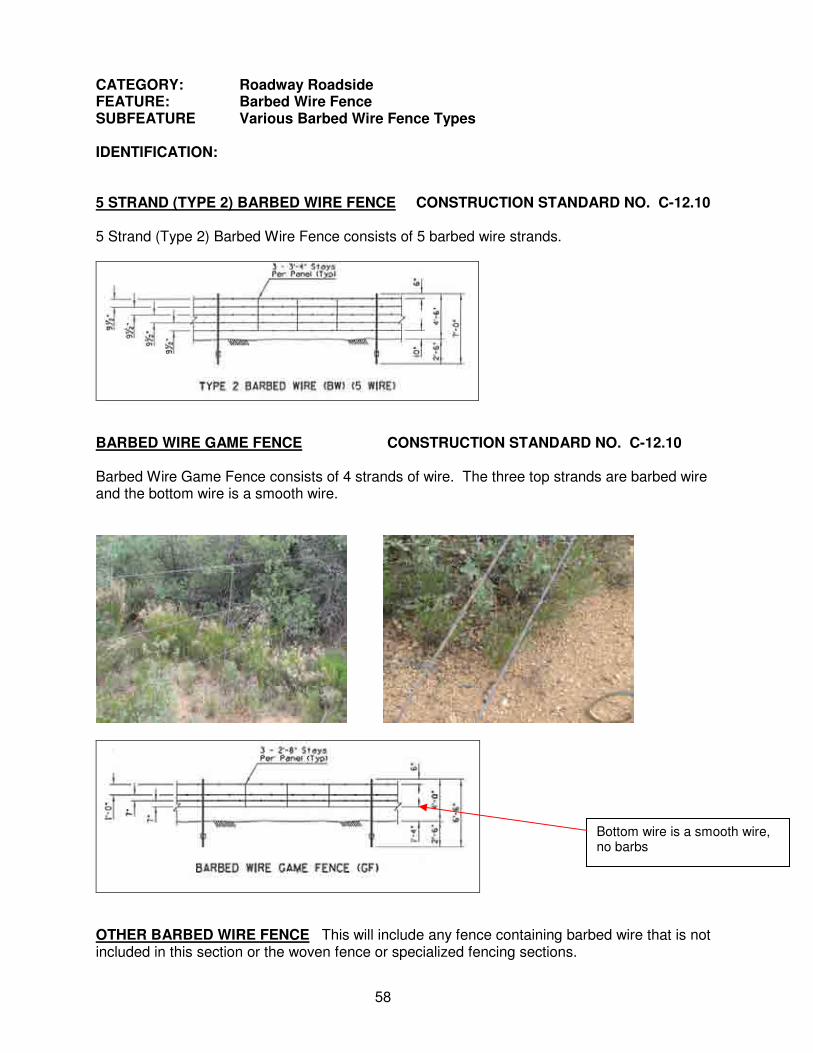
BARBED WIRE GAME FENCE CONSTRUCTION STANDARD NO. C-12.10 Barbed Wire Game Fence consists of 4 strands of wire. The three top strands are barbed wire and the bottom wire is a smooth wire.
OTHER BARBED WIRE FENCE This will include any fence containing barbed wire that is not included in this section or the woven fence or specialized fencing sections.
Bottom wire is a smooth wire, no barbs

59
CATEGORY: Roadway Roadside FEATURE: Chain Link Fence SUBFEATURE Chain Link Fence CONSTRUCTION STANDARD NO. C-12.20 MEASUREMENT INFORMATION: Measurement of Chain Link Fence will start at the beginning of the fence for the section or roadway to be covered and will terminate at the end of the section. MEASUREMENT LOCATION AND FREQUENCY: GPS readings shall be captured at each end of the fence on tangent (straight) sections of the feature. Multiple points must be recorded on curves at appropriate intervals. The GPS readings may be collected at the edge of pavement with the offset distance recorded on the General Tab. No adjustment in offset distance is made for angle points (where fence line changes direction) in the fence line. Wing fences, if present, are not measured due to the excessive amount of time required to measure them. In circumstances where GPS readings cannot be captured, (generally due to atmospheric conditions or obstructions) measurements shall be captured either by electronic measuring devices, measuring wheels or other measuring devices. When saving a record without a GPS reading, you will need to enter an accurate milepost and offset. MEASUREMENT UNIT: Lineal Feet. When multiple GPS readings are recorded, length will automatically be computed when the record is saved. Where physical measurement must be taken, enter the quantity, to the nearest foot, on the hand-held device. Other information to record includes the number of lock and unlocked, hinged gates within a section. GENERAL TAB INFO: You will also be asked to complete the following information on the General Tab: Offset from edge Enter number of feet from edge of pavement to fence when the offset of pavement distance remains constant within the measured section – otherwise enter 0. Various Offset Select from Drop-down – N/A or Various – “Various” is used when Distance Note offset distance from fence to the edge of pavement varies. Select N/A
when entering actual offset from edge of pavement. Number of Locked, Hinged Gates: Enter total number for measured fence section. Number of Unlocked, Hinged Gates: Enter total number for measured fence section. Length: Enter lineal feet ONLY if unable to collect GPS locations. IDENTIFICATION: Identification of the Chain Link Fence is based on the height of the fence
Care should be exercised to not overlook fence that “seems” to be part of another feature.

60
CATEGORY: Roadway Roadside FEATURE: Woven Wire Fence SUBFEATURE Woven Wire Fence CONSTRUCTION STANDARD NO. C-12.20 MEASUREMENT INFORMATION: Measurement of Woven Wire Fence will start at the beginning of the fence for the section or roadway to be covered and will terminate at the end of the section. MEASUREMENT LOCATION AND FREQUENCY: GPS readings shall be captured at each end of the fence on tangent (straight) sections of the feature. Multiple points must be recorded on curves at appropriate intervals. The GPS readings may be collected at the edge of pavement with the offset distance recorded on the General Tab. No adjustment in offset distance is made for angle points (where fence line changes direction) in the fence line. Wing fences, if present, are not measured due to the excessive amount of time required to measure them. In circumstances where GPS readings cannot be captured, (generally due to atmospheric conditions or obstructions) measurements shall be captured either by electronic measuring devices, measuring wheels or other measuring devices. When saving a record without a GPS reading, you will need to enter an accurate milepost and offset. MEASUREMENT UNIT: Lineal Feet. When multiple GPS readings are recorded, length will automatically be computed when the record is saved. Where physical measurement must be taken, enter the quantity, to the nearest foot, on the hand-held device. Other information to record includes the number of lock and unlocked, hinged gates within a section. GENERAL TAB INFO: You will also be asked to complete the following information on the General Tab: Offset from edge Enter number of feet from edge of pavement to fence when the offset of pavement distance remains constant within the measured section – otherwise enter 0. Various Offset Select from Drop-down – N/A or Various – “Various” is used when Distance Note offset distance from fence to the edge of pavement varies. Select N/A
when entering actual offset from edge of pavement. Number of Locked, Hinged Gates: Enter total number for measured fence section. Number of Unlocked, Hinged Gates: Enter total number for measured fence section. Length: Enter lineal feet ONLY if unable to collect GPS locations. IDENTIFICATION: Identification of the various types of Woven Wire Fence is based, in some cases, on the number of barbed wire strands and the distance between the strands. See drawing on following page

61
CATEGORY: Roadway Roadside FEATURE: Woven Wire Fence SUBFEATURE Woven Wire Fence (continued) CONSTRUCTION STANDARD NO. C-12.20 IDENTIFICATION:
Note only difference between Type 1 and Type 2 is distance between top two wires. OTHER WOVEN FENCE Any type of woven fence not covered by Types 1 – 4.

62
CATEGORY: Roadway Roadside FEATURE: Other Specialized Fence SUBFEATURE Other Specialized Fence CONSTRUCTION STANDARD NO. - VARIOUS MEASUREMENT INFORMATION: Measurement of Other Specialized Fence will start at the beginning of the fence for the section or roadway to be covered and will terminate at the end of the section. MEASUREMENT LOCATION AND FREQUENCY: GPS readings shall be captured at each end of the fence on tangent (straight) sections of the feature. Multiple points must be recorded on curves at appropriate intervals. The GPS readings may be collected at the edge of pavement with the offset distance recorded on the General Tab. No adjustment in offset distance is made for angle points (where fence line changes direction) in the fence line. Wing fences, if present, are not measured due to the excessive amount of time required to measure them. In circumstances where GPS readings cannot be captured, (generally due to atmospheric conditions or obstructions) measurements shall be captured either by electronic measuring devices, measuring wheels or other measuring devices. When saving a record without a GPS reading, you will need to enter an accurate milepost and offset. MEASUREMENT UNIT: Lineal Feet. When multiple GPS readings are recorded, length will automatically be computed when the record is saved. Where physical measurement must be taken, enter the quantity, to the nearest foot, on the hand-held device. Other information to record includes the number of lock and unlocked, hinged gates within a section. GENERAL TAB INFO: You will also be asked to complete the following information on the General Tab: Offset from edge Enter number of feet from edge of pavement to fence when the offset of pavement distance remains constant within the measured section – otherwise enter 0. Various Offset Select from Drop-down – N/A or Various – “Various” is used when Distance Note offset distance from fence to the edge of pavement varies. Select N/A
when entering actual offset from edge of pavement. Number of Locked, Hinged Gates: Enter total number for measured fence section. Number of Unlocked, Hinged Gates: Enter total number for measured fence section. Length: Enter lineal feet ONLY if unable to collect GPS locations. IDENTIFICATION: Identification of the various types of Other Specialized Fence is based on its’ design purpose. Much of this fence was designed to manage particular types of animals (elk, sheep and tortoise) or conditions (snow). In the absence of photos or design data, the data collectors will have to rely on local maintenance employees to identify the specific type of fence.

63
CATEGORY: Roadway Roadside FEATURE: Other Specialized Fence SUBFEATURE Other Specialized Fence ELK FENCE
SHEEP FENCE

64
CATEGORY: Roadway Roadside FEATURE: Other Specialized Fence SUBFEATURE Other Specialized Fence TORTOISE FENCE
Tortoise fence may exist by itself, or may be found along with other fence types. Don’t overlook the possibility of multiple fence types.

65
CATEGORY: Roadway Roadside FEATURE: Other Specialized Fence SUBFEATURE Other Specialized Fence SNOW FENCE
There may be additional types of snow fence. Additional photos will be provided as they become available. MISCELLANEOUS FENCE Any type of specialized fence not covered by the above listed types.

66
CATEGORY: Roadway Roadside FEATURE: Cattle Guard SUBFEATURE Cattle Guard CONSTRUCTION STANDARD NO. - VARIOUS MEASUREMENT INFORMATION: Measurement of Cattle guards will be a single point MEASUREMENT LOCATION AND FREQUENCY: A single GPS reading shall be captured in the center of the cattle guard. In circumstances where GPS readings cannot be captured, (generally due to atmospheric conditions or obstructions) the record shall be completed and saved without the GPS reading. When saving a record without a GPS reading, you will need to enter an accurate milepost and offset. MEASUREMENT UNIT: Point feature. A single GPS reading is to be recorded. Other information to record includes the number of grills and the type of cattle guard – pre-cast, poured in place or other. GENERAL TAB INFO: You will also be asked to complete the following information on the General Tab: Number of Grills: Select the number of grills from the drop-down box. IDENTIFICATION: CATTLE GUARD – POURED IN PLACE
These photos are of a poured-in-place cattle guard, meaning that the cattle guard was excavated, formed and poured as a single unit. This type can be easily determined by the lack of joints in the steel and concrete of the structure.
67
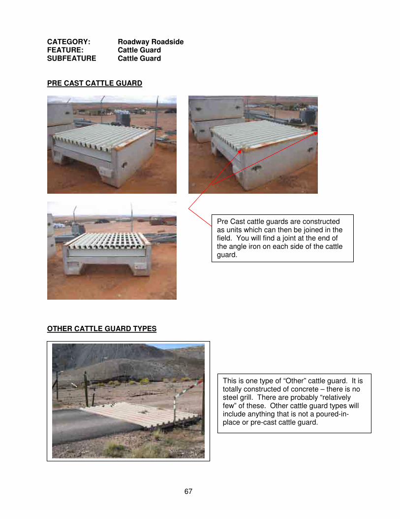
CATEGORY: Roadway Roadside FEATURE: Cattle Guard SUBFEATURE Cattle Guard PRE CAST CATTLE GUARD
OTHER CATTLE GUARD TYPES
Pre Cast cattle guards are constructed as units which can then be joined in the field. You will find a joint at the end of the angle iron on each side of the cattle guard.
This is one type of “Other” cattle guard. It is totally constructed of concrete – there is no steel grill. There are probably “relatively few” of these. Other cattle guard types will include anything that is not a poured-in-place or pre-cast cattle guard.

68
CATEGORY: Roadway Roadside FEATURE: Rest Area SUBFEATURE VARIOUS CONSTRUCTION STANDARD NO. - VARIOUS MEASUREMENT INFORMATION: Measurement of Rest Areas will be a single point. MEASUREMENT LOCATION AND FREQUENCY: A single GPS reading shall be captured at the beginning of the off ramp going into the rest area. In circumstances where GPS readings cannot be captured, (generally due to atmospheric conditions or obstructions) the record shall be completed and saved without the GPS readings. When saving a record without a GPS reading, you will need to enter an accurate milepost and offset. MEASUREMENT UNIT: Point feature. A single GPS reading is to be recorded. GENERAL TAB INFO: There is no General Tab entry required for this feature. IDENTIFICATION: Rest Areas are in two categories – Interstate and Non-Interstate. Interstate Rest Areas are located on the Interstate Highway System, which includes I-8, I-10, I-17 and I-40. These typically include full-service rest areas – rest rooms, phones and vending machines. Non-Interstate Rest Areas will be recorded only when it is a rest area that includes rest rooms, either permanent or portable. Some examples include the Mazatzal rest area on SR 87 south of Payson and the Salt River Canyon rest area on US 60 north of Globe.

69
CATEGORY: Roadway Roadside FEATURE: Walls SUBFEATURE Various CONSTRUCTION STANDARD NO. - VARIOUS MEASUREMENT INFORMATION: Sound Walls will be associated with the mainline roadway. Measurement of walls will start at the beginning of the wall and will terminate at the end of the wall. MEASUREMENT LOCATION AND FREQUENCY: GPS readings shall be captured at each end of the wall on tangent (straight) sections of the feature. Multiple points must be recorded on curves at appropriate intervals. Walls are the only features to be captured in square feet. It is therefore necessary to also capture an average height measurement. In circumstances where GPS readings cannot be captured, (generally due to atmospheric conditions or obstructions) measurements shall be captured either by electronic measuring devices, measuring wheels or other measuring devices. When saving a record without a GPS reading, you will need to enter an accurate milepost and offset. MEASUREMENT UNIT: Square Feet. Requires at least three GPS points. When multiple GPS readings are recorded, length will automatically be computed when the record is saved. For this particular feature it is also necessary to capture the average height of the wall. In many cases this can be accomplished with a tape measure or range pole. Where physical measurement must be taken, enter the quantity, to the nearest .5 foot, on the hand-held device. GENERAL TAB INFO: You will also be asked to complete the following information on the General Tab: Length: Enter length ONLY if no GPS data is gathered. IDENTIFICATION: Walls will fall into two categories – Sound Walls shielding nearby homes or business from roadway noise, or Retaining Walls which hold fill behind them. Care should be taken when making a determination of a retain wall. The rule is that the identification of a feature is made based on its design purpose. In many cases, concrete barriers are modified in height and include weep holes which also allow the barrier to serve as a retaining wall, however the identification of the wall will be a concrete barrier. SOUND WALLS
Note that often sound walls may be found with other features. In the above, right photo, the tan sound wall is immediately adjacent to a concrete barrier on the left side of the sound wall.

70
CATEGORY: Roadway Roadside FEATURE: Walls SUBFEATURE Various SOUND WALLS (continued)
Note barrier adjacent to sound wall and retaining wall adjacent to sound wall. RETAINING WALLS
END ROADWAY ROADSIDE CATEGORY

71
CATEGORY: Roadway Shoulder FEATURE: Roadway Shoulders SUBFEATURE Various Shoulder Types MEASUREMENT INFORMATION: Measurement of Roadway Shoulder will start at the beginning of the shoulder section, either paved or unpaved, for the section or roadway to be covered and will terminate at the end of the section. Roadway Shoulder data IS NOT collected in guardrail sections, in roadway cuts or in areas where cut ditches extend beyond the end of the cut. Generally
• Collect shoulder data in curb and gutter areas where there is 5’ or more of unpaved surface behind the curb. • Do not Collect shoulder data in curb and gutter areas where there is sidewalk immediately adjacent to the curb. MEASUREMENT LOCATION AND FREQUENCY: GPS readings shall be captured at each end of the shoulder on tangent (straight) sections of the feature. Multiple points must be recorded on curves at appropriate intervals. The GPS Readings may be collected at the edge of the pavement, from the vehicle, utilizing external antenna(s). In circumstances where GPS readings cannot be captured, (generally due to atmospheric conditions or obstructions) measurements shall be captured either by electronic measuring devices, measuring wheels or other measuring devices. When saving a record without a GPS reading, you will need to enter accurate milepost information. MEASUREMENT UNIT: Lineal Feet. When multiple GPS readings are recorded, length will automatically be computed when the record is saved. Where physical measurement must be taken, enter the quantity, to the nearest foot, on the hand-held device. GENERAL TAB INFO: No additional information is required. IDENTIFICATION: Identification of the Shoulder is based on either a paved shoulder or an unpaved shoulder.
The roadway surface includes the travel lanes and the paved area behind the shoulder stripe. The shoulder starts at the edge of pavement (Unpaved Shoulder) or where the level roadway surface begins to break at a downward angle (Paved or Unpaved Shoulder).
Roadway Cross Section
Paved Surface
Shoulder
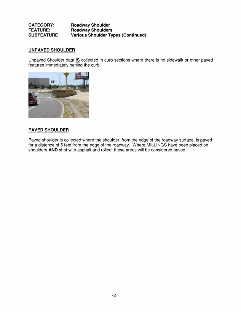
72
CATEGORY: Roadway Shoulder FEATURE: Roadway Shoulders SUBFEATURE Various Shoulder Types (Continued) UNPAVED SHOULDER Unpaved Shoulder data IS collected in curb sections where there is no sidewalk or other paved features immediately behind the curb.
PAVED SHOULDER Paved shoulder is collected where the shoulder, from the edge of the roadway surface, is paved for a distance of 5 feet from the edge of the roadway. Where MILLINGS have been placed on shoulders AND shot with asphalt and rolled, these areas will be considered paved.

73
CATEGORY: Roadway Surface FEATURE: Turnout SUBFEATURE Turnout CONSTRUCTION STANDARD NO. - VARIOUS MEASUREMENT LOCATION AND FREQUENCY: A single GPS reading shall be captured at the center (when possible) of the Turnout, at the roadway shoulder, in line with the edge of pavement on either side of the turnout. In circumstances where GPS readings cannot be captured, (generally due to atmospheric conditions or obstructions) the record shall be created and saved without the GPS reading. When saving a record without a GPS reading, you will need to enter an accurate milepost and offset. Local intersecting streets will be considered as turnouts. Intersecting interstate or state highways, frontage roads or ramps on interchanges will NOT be considered Turnouts. Curb depressions for driveways are NOT considered turnouts MEASUREMENT UNIT: Point feature. A single GPS reading is to be recorded. SUPER ASSETS: Turnouts are one of the few assets that have been designed as a Super Asset. This means that the collection and quantification of multiple assets, in one record, is possible. This represents a considerable time savings in data collection. Turnouts often times have additional features located with them, such as cattleguards and hinged gates (locked or unlocked), which can be associated with the Turnout GPS point. The Super Asset makes it possible to collect all three feature types in one record. A GPS point is generally collected at the center of the Turnout, at the roadway shoulder, in line with the edge of pavement on either side of the turnout. Though a point is not collected at the cattle guard or gate; they can be easily located on the turnout. The tradeoff, in this case, of accuracy for the sake of time, has little impact on the data collected. If either hinged gates or cattleguards are located at locations other than turnouts, these features can still be collected, but must be collected as individual assets under Roadway Roadside Category. On the GPS data collection device, when searching for either a cattle guard or hinged gate that has been created under the Super Asset Turnout record, you must look under either the cattle guard or hinged gate features under the Roadway Roadside Category. SUPER ASSET TAB: Allows the collection of either hinged gates or cattleguards, or both, within the same record as the Turnout. Select the appropriate features form the dropdown boxes. In the case of cattle guards, select the number of grills from the dropdown box. Enter the appropriate number of locked or unlocked gates. DO NOT RECORD GATES IN PRIVATELY OWNED FENCE. GENERAL TAB INFO: No entries are required on the General Tab IDENTIFICATION: Select the type of turnout to be collected, either paved or unpaved. Only enter turnouts which are constructed and maintained. Do not collect areas where roads (turnouts) are established simply by repeated use. A turnout can be defined as a constructed or improved access to an improved intersecting street or road, either paved or unpaved.

74
CATEGORY: Roadway Surface FEATURE: Turnout SUBFEATURE Turnout (continued) When possible, enter the identification of the turnout on the Common Tab of the FISDC program on the GPS data collection device. Identification examples can be FR (Forest Road) 131, Joe’s Market, etc.
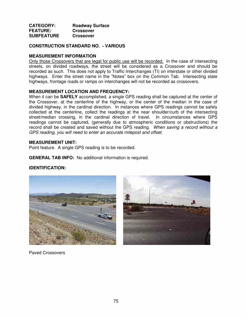
75
CATEGORY: Roadway Surface FEATURE: Crossover SUBFEATURE Crossover CONSTRUCTION STANDARD NO. - VARIOUS MEASUREMENT INFORMATION Only those Crossovers that are legal for public use will be recorded. In the case of intersecting streets, on divided roadways, the street will be considered as a Crossover and should be recorded as such. This does not apply to Traffic Interchanges (TI) on interstate or other divided highways. Enter the street name in the ”Notes” box on the Common Tab. Intersecting state highways, frontage roads or ramps on interchanges will not be recorded as crossovers. MEASUREMENT LOCATION AND FREQUENCY: When it can be SAFELY accomplished, a single GPS reading shall be captured at the center of the Crossover, at the centerline of the highway, or the center of the median in the case of divided highway, in the cardinal direction. In instances where GPS readings cannot be safely collected at the centerline, collect the readings at the near shoulder/curb of the intersecting street/median crossing, in the cardinal direction of travel. In circumstances where GPS readings cannot be captured, (generally due to atmospheric conditions or obstructions) the record shall be created and saved without the GPS reading. When saving a record without a GPS reading, you will need to enter an accurate milepost and offset. MEASUREMENT UNIT: Point feature. A single GPS reading is to be recorded. GENERAL TAB INFO: No additional information is required. IDENTIFICATION:
Paved Crossovers
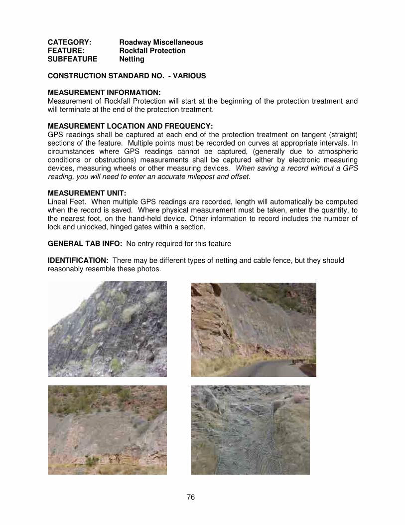
76
CATEGORY: Roadway Miscellaneous FEATURE: Rockfall Protection SUBFEATURE Netting CONSTRUCTION STANDARD NO. - VARIOUS MEASUREMENT INFORMATION: Measurement of Rockfall Protection will start at the beginning of the protection treatment and will terminate at the end of the protection treatment. MEASUREMENT LOCATION AND FREQUENCY: GPS readings shall be captured at each end of the protection treatment on tangent (straight) sections of the feature. Multiple points must be recorded on curves at appropriate intervals. In circumstances where GPS readings cannot be captured, (generally due to atmospheric conditions or obstructions) measurements shall be captured either by electronic measuring devices, measuring wheels or other measuring devices. When saving a record without a GPS reading, you will need to enter an accurate milepost and offset. MEASUREMENT UNIT: Lineal Feet. When multiple GPS readings are recorded, length will automatically be computed when the record is saved. Where physical measurement must be taken, enter the quantity, to the nearest foot, on the hand-held device. Other information to record includes the number of lock and unlocked, hinged gates within a section. GENERAL TAB INFO: No entry required for this feature IDENTIFICATION: There may be different types of netting and cable fence, but they should reasonably resemble these photos.

77
CATEGORY: Roadway Miscellaneous FEATURE: Rockfall Protection SUBFEATURE Cable Fence IDENTIFICATION:

78
CATEGORY: Roadway Miscellaneous FEATURE: Safety Pullout SUBFEATURE Safety Pullout CONSTRUCTION STANDARD NO. - VARIOUS MEASUREMENT INFORMATION: Measurement of safety pullouts will be a single point. MEASUREMENT LOCATION AND FREQUENCY: A single GPS reading shall be captured at the beginning of the center of the pullout, at the edge of the roadway. In circumstances where GPS readings cannot be captured, (generally due to atmospheric conditions or obstructions) measurements shall be captured either by electronic measuring devices, measuring wheels or other measuring devices. When saving a record without a GPS reading, you will need to enter an accurate milepost and offset. MEASUREMENT UNIT: Point feature. A single GPS reading is to be recorded. GENERAL TAB INFO: No additional information is required. IDENTIFICATION: Safety pullouts are limited to those areas that are appropriately signed as safety pullouts. They will generally be located at the top of downgrades. These pullouts allow drivers to stop and check their vehicles prior to entering a steep downgrade.

79
CATEGORY: Roadway Miscellaneous FEATURE: Truck Escape Ramp SUBFEATURE Truck Escape Ramp CONSTRUCTION STANDARD NO. - VARIOUS MEASUREMENT INFORMATION: Measurement of Truck Escape Ramps will be a single point. MEASUREMENT LOCATION AND FREQUENCY: A single GPS reading shall be captured at the beginning of the taper entering the truck escape ramp. In circumstances where GPS readings cannot be captured, (generally due to atmospheric conditions or obstructions) measurements shall be captured either by electronic measuring devices, measuring wheels or other measuring devices. When saving a record without a GPS reading, you will need to enter an accurate milepost and offset. MEASUREMENT UNIT: Point feature. A single GPS reading is to be recorded. GENERAL TAB INFO: No additional information is required. IDENTIFICATION: Truck Escape Ramps are limited to those areas constructed and signed as Runaway Truck Ramps.

80
CATEGORY: Roadway Miscellaneous FEATURE: Sidewalk SUBFEATURE Sidewalk CONSTRUCTION STANDARD NO. - VARIOUS MEASUREMENT INFORMATION: Measurement of Sidewalk will start at the beginning of the sidewalk and will terminate at the end of the sidewalk. MEASUREMENT LOCATION AND FREQUENCY: GPS readings shall be captured at the side nearest the roadway at each end of the sidewalk on tangent (straight) sections of the feature. Multiple points must be recorded on curves at appropriate intervals. In circumstances where GPS readings cannot be captured, (generally due to atmospheric conditions or obstructions) measurements shall be captured either by electronic measuring devices, measuring wheels or other measuring devices. When saving a record without a GPS reading, you will need to enter an accurate milepost and offset. MEASUREMENT UNIT: Lineal Feet. When multiple GPS readings are recorded, length will automatically be computed when the record is saved. Where physical measurement must be taken, enter the quantity, to the nearest foot, on the hand-held device. Other information to record includes the number of lock and unlocked, hinged gates within a section. GENERAL TAB INFO: Enter L. Ft. manual measurement only if GPS is unavailable IDENTIFICATION: Sidewalk may be found immediately next to the roadway, or there may be some separation between the sidewalk and roadway. Take care not to ignore the curb and gutter measurements or unpaved shoulder in areas where sidewalk is located.

81
CATEGORY: Roadway Miscellaneous FEATURE: ADA Ramps SUBFEATURE ADA Ramps CONSTRUCTION STANDARD NO. - VARIOUS MEASUREMENT INFORMATION: Measurement of ADA Ramps will be a single point MEASUREMENT LOCATION AND FREQUENCY: A single GPS reading shall be captured in the center of the ADA Ramp, at the curb line, in instances where there is only 1 ADA Ramp at a location. At intersections there are typically 2 ADA Ramps on a street corner – one for each street to be crossed. In these situations, where two ramps exist on a corner, collect the GPS data midway between the two ramps, at the curb line, and record a quantity of 2 in the drop-down box on the General Tab. In circumstances where GPS readings cannot be captured, (generally due to atmospheric conditions or obstructions) measurements shall be captured either by electronic measuring devices, measuring wheels or other measuring devices. When saving a record without a GPS reading, you will need to enter an accurate milepost and offset. MEASUREMENT UNIT: Point feature. A single GPS reading is to be recorded. GENERAL TAB INFO: Enter the number of ADA Ramps per street corner from the drop-down box – select 1 or 2. IDENTIFICATION: The finish treatments on ADA Ramps may differ. Many of the existing ADA Ramps have lines in them to help visually impaired persons identify the ramp with the use of their cane. Recent changes to ADA law now require a different treatment. Many of the new ramps have raised dots on them.

82
CATEGORY: Roadway Miscellaneous FEATURE: Call Box SUBFEATURE Call Box CONSTRUCTION STANDARD NO. - VARIOUS MEASUREMENT INFORMATION: Measurement of Call Boxes will be a single point MEASUREMENT LOCATION AND FREQUENCY: A single GPS reading shall be captured at the call box location. In circumstances where GPS readings cannot be captured, (generally due to atmospheric conditions or obstructions) simply save the record. When saving a record without a GPS reading, you will need to enter an accurate milepost and offset. MEASUREMENT UNIT: Point feature. A single GPS reading is to be recorded. GENERAL TAB INFO: No additional info required. IDENTIFICATION: Emergency call boxes are usually well signed. There are few call boxes in Arizona, with I-19 south of Tucson having the most. US 93 from Wickenburg to I-40 has a few. There may be other locations in the state.

83
CATEGORY: Roadway Miscellaneous FEATURE: Tunnel SUBFEATURE Tunnel CONSTRUCTION STANDARD NO. - VARIOUS MEASUREMENT INFORMATION: Measurement of Tunnels will be a single point MEASUREMENT LOCATION AND FREQUENCY: A single GPS reading shall be captured at the entrance to the tunnel, IN THE CARDINAL DIRECTION, when both directions of travel are within a single tunnel. When travel is limited to one-way, a single GPS reading should be collected at the entrance to the tunnel, regardless of cardinal direction. The GPS reading should be taken at the centerline when possible, considering GPS reception, traffic flow and safety. Otherwise the reading may be collected at the right shoulder. In circumstances where GPS readings cannot be captured, (generally due to atmospheric conditions or obstructions) the record shall be created and saved without the GPS reading. When saving a record without a GPS reading, you will need to enter an accurate milepost and offset. MEASUREMENT UNIT: Point feature. A single GPS reading is to be recorded. GENERAL TAB INFO: Select Type 1 or Type 2. A Type 1 Tunnel is a tunnel that is staffed. The only tunnel that meets this criterion in Arizona is the Deck Park Tunnel located in Phoenix on I-10, between 7th Avenue and 7th Street. A Type 2 Tunnel is a non-staffed tunnel. This would include any tunnel except for the Deck Park Tunnel. IDENTIFICATION: Type 1 Tunnel

84
Type 2 Tunnel
END ROADWAY MISCELLANEOUS CATEGORY

85
CATEGORY: Roadway Structure FEATURE: Structure SUBFEATURE Structure CONSTRUCTION STANDARD NO. - VARIOUS MEASUREMENT INFORMATION: Measurement of Structures will be a single point. Currently we are exploring the possibility of importing information on the structures from the Bridge Records. This is not resolved at this time. MEASUREMENT LOCATION AND FREQUENCY: A single GPS reading shall be captured at the near end of bridges, IN THE CARDINAL DIRECTION, when the structure supports both directions of traffic. When travel is limited to one-way, a single GPS reading should be collected at the near end of the bridge, regardless of cardinal direction. The GPS reading should be taken at the centerline when possible, considering GPS reception, traffic flow and safety. Otherwise the reading may be collected at the right shoulder. In circumstances where GPS readings cannot be captured, (generally due to atmospheric conditions or obstructions) the record shall be created and saved without the GPS reading. When saving a record without a GPS reading, you will need to enter an accurate milepost and offset. MEASUREMENT UNIT: Point feature. A single GPS reading is to be recorded. GENERAL TAB INFO: Includes the structure name, number, and surface type. The bridge structure information will be provided in an appendix in this book. Bridge information may also be obtained via the adotnet at the following URL. http://aidw/dw/reportmanager.aspx. Authorization must be requested from the ADOT Data Warehouse in order to access the records. It will be necessary to view the bridge photos to determine surface type.
END ROADWAY STRUCTURE CATEGORY