b c d cables - khaidemenko.khai.edu/uploads/editor/41/4710/sitepage...fig. 8 a cable and strut...
TRANSCRIPT

V. DEMENKO MECHANICS OF MATERIALS 2017
9/27/2017 4:13:35 PMW:\+МЕХАНИКА МАТЕРИАЛОВ W\082 LECTURES 2017\11 Strength and Rigidity of a Bar in Tension and Compression.doc
1
LECTURE 11 Strength and Rigidity of a Bar in Tension and Compression
Tension and compression are the types of simple deformation in which only one
internal force factor, a normal force xN , appears in the cross section of a bar: 0xN ,
0z y x y zQ Q M M M . The examples of tension-compression deformation of
structural elements are represented in Figs 1–16.
P
Cables
Reinforcedconcrete slab
Fig. 1 The vertical load P acting on the wheel
compresses its vertical axis
Fig. 2 A reinforced concrete slab is lifted by
4 tensile cables
A
B C D
E
FP
H
G
b b b b
h
H
Pump rod
d
Piston
L
Fig. 3 The truss ABCDEFGH is part of a wood
bridge. The truss members are hinged
Fig. 4 A pump moves a piston up and down
in a deep water well. Pump rod is periodically
tensile or compressed

V. DEMENKO MECHANICS OF MATERIALS 2017
9/27/2017 4:13:35 PMW:\+МЕХАНИКА МАТЕРИАЛОВ W\082 LECTURES 2017\11 Strength and Rigidity of a Bar in Tension and Compression.doc
2
Fig. 5 The piston in an engine is attached to a
connecting rod AB, which intern is connected to
a crank arm BC. Both elements are compressed
or tensile
Fig. 6 A car is pulled slowly up a steep
inclined track by a steel cable which is tensile
Fig. 7 Cylinder with piston and clamping tensile
bolts
Fig. 8 A cable and strut assembly ABC
supports a vertical load P. The cable and
strut are in tension-compression.
Fig. 9 A vertical load P is supported by the
truss ABCD which are pinned connected and
Fig. 10 A bungee cord is attached to pegs

V. DEMENKO MECHANICS OF MATERIALS 2017
9/27/2017 4:13:35 PMW:\+МЕХАНИКА МАТЕРИАЛОВ W\082 LECTURES 2017\11 Strength and Rigidity of a Bar in Tension and Compression.doc
3
therefore are tensile or compressed and pulled at its midpoint by a force P
Fig. 11 A tubular post is guyed by two cables
fitted with turnbuckles. The cables are tightened
by rotating the turnbuckles
Fig. 12 Lifeboat hanges from two ship’s
davits. Cables attached to the lifeboat pass
over the pulleys and are really tensile
Fig. 13 An aluminum bar AB is attached to a
support by a pin and is tensile by a P force
Fig. 14 A ship’s spar is attached at the base
of a must by a pin connection. It is
compressed by a P force

V. DEMENKO MECHANICS OF MATERIALS 2017
9/27/2017 4:13:35 PMW:\+МЕХАНИКА МАТЕРИАЛОВ W\082 LECTURES 2017\11 Strength and Rigidity of a Bar in Tension and Compression.doc
4
A C
B
1.5 m
Fig. 15 A rigid bar AB is supported by two
cables CE and BD which are tensile under P
loading
Fig. 16 A steel wire ABC supporting a lamp
is tensile
1 Hypothesis of Plane Sections
If before loading the ends of the segments (left points a, c, e and also right ones
b, d, f) (see Fig. 15) are situated at the planes A and B, then after loading they also will
be situated at the planes, accordingly, 'A and 'B (left points 'a , 'c , 'e and also right
ones b , d , f ). This fact is named as hypothesis of plane sections, i.e. 'A A and
'B B. It is accepted as fundamental and confirmed by experimental tests.
Note the experimentally proven fact that absolute elongations for all elementary
segments (ab, cd, ef,...) taken in the portion dx are the same
ab cd ef dx , and strains xdx
constdx
, (1)
Fig.17

V. DEMENKO MECHANICS OF MATERIALS 2017
9/27/2017 4:13:35 PMW:\+МЕХАНИКА МАТЕРИАЛОВ W\082 LECTURES 2017\11 Strength and Rigidity of a Bar in Tension and Compression.doc
5
i.e. the state of strain is homogeneous over the cross-section of loaded bar.
2 Calculation of Stresses in Tension-Compression
It was mentioned above, that relation between normal force xN and normal
stress x is
x x
A
N dA . (2)
According to Hooke's law
x xE , (3)
( E const ) and taking into account the expression (1), we have
x x x x
A
N E dA E A A .
Then
xx
N
A . (4)
As it is seen from expression (4) the normal stresses in tension (or compression)
are distributed uniformly over the cross-section of a rod. The formula (4) means, that
to find acting stresses in the cross-section it is necessary to know from normal force
diagram the value of corresponding normal force in the cross-section and also cross-
sectional area of the rod.
3 Condition of Strength in Tension-Compression
To estimate the strength of the bar in tension and compression, it is necessary to
create the condition of strength which states that the maximum stress max in the
bar must not exceed the allowable stress of the bar material :
maxt t , and maxc c
, where (5)
t – allowable stress in tension; c – allowable stress in compression.

V. DEMENKO MECHANICS OF MATERIALS 2017
9/27/2017 4:13:35 PMW:\+МЕХАНИКА МАТЕРИАЛОВ W\082 LECTURES 2017\11 Strength and Rigidity of a Bar in Tension and Compression.doc
6
The section of the bar in which the stress max acts is called the critical section.
Noting that
maxmax
xN
A
(6)
and following the condition of strength
maxmax
xN
A
, (7)
it is possible to solve three practical problems as follows:
(1) check the strength of a bar for the specified load and cross-sectional area
using condition
max or maxmax
xN
A
; (8)
(2) determine the cross-sectional area A for the specified load and allowable
stress :
xA N ; (9)
(3) determine the allowable load on a bar for specified cross-sectional area and
allowable stress taking into account that
xN A , (10)
where xN – allowable normal force.
4 Determination of Strains
According to expression (3) x xE .
Replace x by xN A and x by dx
dx
(see Fig. 17). We obtain then
xN dxdx
EA . (11)
V. DEMENKO MECHANICS OF MATERIALS 2017
9/27/2017 4:13:35 PMW:\+МЕХАНИКА МАТЕРИАЛОВ W\082 LECTURES 2017\11 Strength and Rigidity of a Bar in Tension and Compression.doc
7
The total elongation of the bar along the length l is
x
l l
N dxdx
EA or
0
lxN dx
lEA
. (12)
When the bar is loaded at the ends of portions only, then normal force xN F is
independent of x. If in addition, the bar has constant cross-sectional area A, we obtain
from expression (12):
xN ll
EA . (13)
For stepped bar total elongation will be as follows:
1 1
in n
x ii
i ii i
N ll l
E A
, (14)
where i is number of portion.
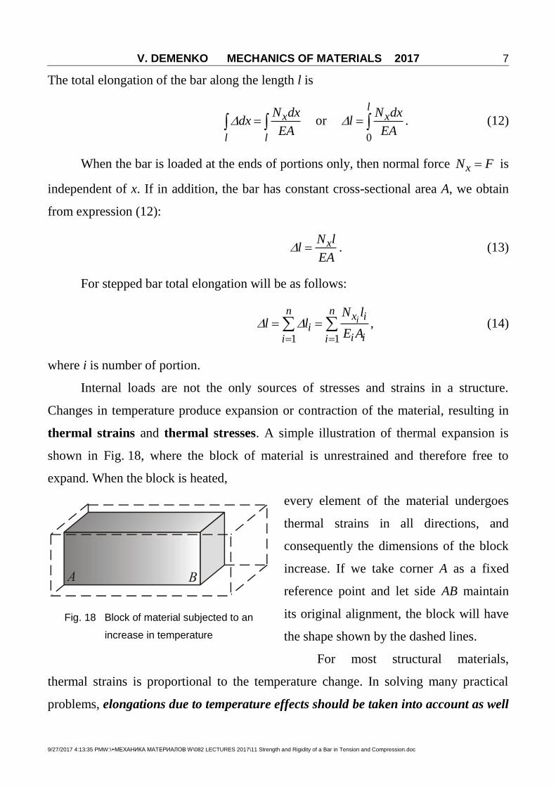
Internal loads are not the only sources of stresses and strains in a structure.
Changes in temperature produce expansion or contraction of the material, resulting in
thermal strains and thermal stresses. A simple illustration of thermal expansion is
shown in Fig. 18, where the block of material is unrestrained and therefore free to
expand. When the block is heated,
every element of the material undergoes
thermal strains in all directions, and
consequently the dimensions of the block
increase. If we take corner A as a fixed
reference point and let side AB maintain
its original alignment, the block will have
the shape shown by the dashed lines.
For most structural materials,
thermal strains is proportional to the temperature change. In solving many practical
problems, elongations due to temperature effects should be taken into account as well
Fig. 18 Block of material subjected to an
increase in temperature

V. DEMENKO MECHANICS OF MATERIALS 2017
9/27/2017 4:13:35 PMW:\+МЕХАНИКА МАТЕРИАЛОВ W\082 LECTURES 2017\11 Strength and Rigidity of a Bar in Tension and Compression.doc
8
as elongations resulting from stress . In this case the method of superposition is
used and total elongation may be written as the sum:
, xt
N ll N t t l
EA , (15)
where t is the linear coefficient of thermal expansion of the material; t is a
change of temperature.
5 Condition of Rigidity in Tension-Compression
(a) in tension
maxmax
xN ll l
EA
; (16)
(b) in compression
maxmax
| |xN ll l
EA
, (17)
where l is the allowable elongation.
Example 1 Stresses and elongations in statically determinate rod in tension-
compression.
Given: 1 10F kN, 2 40F kN, 3 60F kN, 3a m, 4b m, 5c m, 112 10 E Pa,
42 10 A m2.
R.D.: 1) calculate normal forces in the rod cross-sections and design the graph of their
distribution along the rod length;
2) calculate acting stresses in the rod cross-sections and design the graph of their
distribution along the rod length;
3) draw the graph of the rod cross-section displacements.
Solution
1) Calculating the normal forces in cross-sections of the rod using the method of
section:

V. DEMENKO MECHANICS OF MATERIALS 2017
9/27/2017 4:13:35 PMW:\+МЕХАНИКА МАТЕРИАЛОВ W\082 LECTURES 2017\11 Strength and Rigidity of a Bar in Tension and Compression.doc
9
I–I 0 x c
0IxN x ;
II–II 0 /3x b
1 10 IIxN x F kN;
III–III 0 2 /3x b
1 3 10 60 50 IIIxN x F F kN;
IV–IV 0 x a
1 3 2 10 60 40 10 IVxN x F F F kN.
2) Calculating the stresses in cross-sections of the rod:
I–I 0 x c
0Ix x ;
II–II 0 /3x b
3
4
10 1025
2 2 2 10
IIII xx
N xx
A MPa;
III–III 0 2 /3x b
3
4
50 10125
2 2 2 10
IIIIII xx
N xx
A MPa;
IV–IV 0 x a
3
4
10 1050
2 10
IVIV xx
N xx
A MPa.
3) Determination of the rod elongations.
To solve this problem, we will use the following formula: xN xl x kx
EA . Let us
begin determining the displacements of the portions boundaries (points E, D, C, A)

V. DEMENKO MECHANICS OF MATERIALS 2017
9/27/2017 4:13:35 PMW:\+МЕХАНИКА МАТЕРИАЛОВ W\082 LECTURES 2017\11 Strength and Rigidity of a Bar in Tension and Compression.doc
10
calculating corresponding segments elongations. In this, we will use point B as the
origin. Corresponding displacements are
Fig. 19
33
. 11 4
10 10 30.75 10
2 10 2 10
IVx
p E BEN a
lEA
m.
3 3.
20.75 10 0.75 10
3 2
IIIx
p D BD BE EDN b
l l lEA
33 3 3
11 4
50 10 2 40.75 10 1.667 10 2.417 10
3 2 2 10 2 10
m.
3 3. 2.417 10 2.417 10
3 2
IIx
p C BC BD DCN b
l l lEA
33 3 3
11 4
10 10 42.417 10 0.167 10 2.25 10
3 2 2 10 2 10
m.

V. DEMENKO MECHANICS OF MATERIALS 2017
9/27/2017 4:13:35 PMW:\+МЕХАНИКА МАТЕРИАЛОВ W\082 LECTURES 2017\11 Strength and Rigidity of a Bar in Tension and Compression.doc
11
3 3 3. 2.25 10 2.25 10 0 2.25 10
3
Ix
p A BA BC CAN c
l l lEA
m.
Note: “+” sign of the point displacement means the positive elongation of the
corresponding segment, i.e. down directed displacement of the point. In our example,
all cross-sections move downward.
Example 2 Calculation of allowable load for rod system
The contraption shown in Fig. 20a consists of a horizontal beam ABC supported by two
vertical bars BD and CE. Bar CE is pinned at both ends but bar BD is fixed to the
foundation at its lower end. The distance from A to B is 450 mm and from B to C is
225 mm. Bars BD and CE have lengths of 480 mm and 600 mm, respectively, and their
cross-sectional areas are 1020 mm2 and 520 mm
2, respectively. The bars are made of
steel having a modulus of elasticity 205E GPa. Assuming that beam ABC is rigid,
find the maximum allowable load maxP if the displacement of point A is limited to
1.0 mm.
Solution To find the displacement of point A, we need to know the displacements of
points B and C. Therefore, we must find the changes in lengths of bars BD and CE,
using the general equation / NL EA . We begin by finding the forces in the bars from
a free-body diagram of the beam (Fig. 20b). Because bar CE is pinned at both ends, it is
a "two-force" member and transmits only a vertical force CEF to the beam. However,
bar BD can transmit both a vertical and a horizontal force. From equilibrium of beam
ABC in the horizontal direction, we see that the horizontal force vanishes.
Two additional equations of equilibrium enable us to express the forces BDF and CEF
in terms of the load P. Thus, by taking moments about point B and then summing
forces in the vertical direction, we find
2CEF P and 3BDF P . (1)
Note that the force CEF acts downward on bar ABC and the force BDF acts upward.
Therefore, member CE is in tension and member BD is in compression.
The shortening of member BD is

V. DEMENKO MECHANICS OF MATERIALS 2017
9/27/2017 4:13:35 PMW:\+МЕХАНИКА МАТЕРИАЛОВ W\082 LECTURES 2017\11 Strength and Rigidity of a Bar in Tension and Compression.doc
12
62
(3 )(480 mm)6.887 10 mm
(205 GPa)(1020 mm )
BD BDBD
BD
F L PP
EA (P = newtons) (2)
Note that the shortening BD is expressed in millimeters provided the load P is
expressed in newtons. Similarly, the elongation of member CE is
62
(2 )(600 mm)11.26 10 mm
(205 GPa)(520 mm )
CE CECE
CE
F L PP
EA (P = newtons) (3)
Again, the displacement is expressed in millimeters provided the load P is expressed in
newtons. Knowing the changes in lengths of the two bars, we can now find the
displacement of point A.
A diagram of displacements compatibility showing the relative positions of points A,
B, and C is sketched in Fig. 20c. Line ABC represents the original alignment of the
three points. After the load P is applied, member BD shortens by the amount BD and
point B moves to B'. Also, member CE elongates by the amount CE and point C
moves to C'. Because the beam ABC is assumed to be rigid, points A', B', and C' lie on a
straight line.
For clarity, the displacements are highly exaggerated in the diagram. In reality, line
ABC rotates through a very small angle to its new position A'B'C'.
Using similar triangles, we can now find the relationships between the
displacements at points A, B, and C. From triangles A'A''C' and B'B"C' we get
A A B B
A C B C
or
450 225 225
A CE BD CE
(4)
in which all terms are expressed in millimeters. Substituting for BD and CE from
Eqs. (2) and (3) gives
6 6 611.26 10 6.887 10 11.26 10
450 225 225
A P P P
.

V. DEMENKO MECHANICS OF MATERIALS 2017
9/27/2017 4:13:35 PMW:\+МЕХАНИКА МАТЕРИАЛОВ W\082 LECTURES 2017\11 Strength and Rigidity of a Bar in Tension and Compression.doc
13
Finally, we substitute for A its limiting
value of 1.0 mm and solve the equation for
the load P. The result is
max 23,200 N (or 23.2 kN)P P .
When the load reaches this value, the
downward displacement at point A is
1.0 mm.
Note 1: Since the structure behaves in a
linearly elastic manner, the displacements
are proportional to the magnitude of the
load. For instance, if the load is one-half of
maxP , that is, if 11.6P kN, the downward
displacement of point A is 0.5 mm.
Note 2: To verify our assumption that line
ABC rotates through a very small angle, we
can calculate the angle of rotation from
the displacement diagram (Fig. 17c), as
follows:
tan675 mm
A CEA A
A C
. (5)
The displacement A , of point A is 1.0 mm, and the elongation CE of bar CE is found
from Eq. (3) by substituting 23,200P N; the result is 0.261CE mm. Therefore,
from Eq. (5) we get
1.0 mm 0.261mm 1.261mmtan 0.001868
675 mm 675 mm
from which 0.11 . This angle is so small that if we tried to draw the displacement
diagram to scale, we would not be able to distinguish between the original line ABC
Fig. 20 Horizontal absolutely rigid beam ABC
supported by 2 vertical bars
V. DEMENKO MECHANICS OF MATERIALS 2017
9/27/2017 4:13:35 PMW:\+МЕХАНИКА МАТЕРИАЛОВ W\082 LECTURES 2017\11 Strength and Rigidity of a Bar in Tension and Compression.doc
14
and the rotated line A'B'C'. Thus, when working with displacement diagrams, we
usually can consider the displacements to be very small quantities, thereby simplifying
the geometry. In this example we were able to assume that points A, B, and C moved
only vertically, whereas if the displacements were large, we would have to consider
that they moved along curved paths.
6 Statically Indeterminate Rods and Rod Systems in Tension or Compression
By a statically determinate system is meant a system for which all the
reactions of the supports and internal force factors can be determined by means of
equations of equilibrium.
By a statically indeterminate system is meant a system for which the external
reactions and all the internal force factors cannot be determined by means of the
method of sections and equations of equilibrium. In this case, it is necessary to create
additional equations connecting displacements of points or cross-sections, taking into
account that displacements are connected with internal forces by Hooke’s law. These
equations are named as compatibility equations. The method of opening of static
indeterminacy is illustrated below.
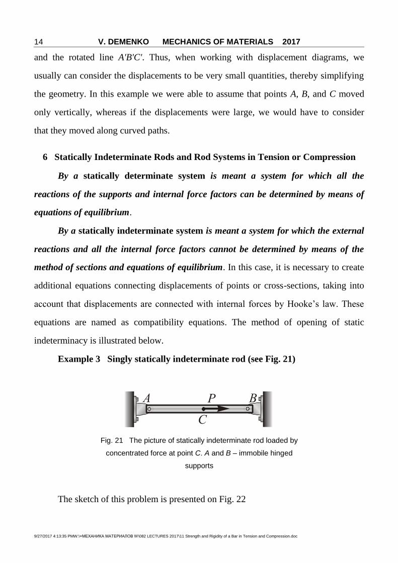
Example 3 Singly statically indeterminate rod (see Fig. 21)
Fig. 21 The picture of statically indeterminate rod loaded by
concentrated force at point C. A and B – immobile hinged
supports
The sketch of this problem is presented on Fig. 22

V. DEMENKO MECHANICS OF MATERIALS 2017
9/27/2017 4:13:35 PMW:\+МЕХАНИКА МАТЕРИАЛОВ W\082 LECTURES 2017\11 Strength and Rigidity of a Bar in Tension and Compression.doc
15
Given: F, a, b. A straight homogeneous bar
is rigidly fixed at the ends and subjected to
a longitudinal force F.
It is necessary to determine the
normal force distribution and to draw the
diagram xN x .
Note. Two reactions of supports AR and
BR cannot be determined from one
equation of equilibrium
0 x A BF R R F ,
therefore the system is singly statically
indeterminate.
It is necessary to have one more
equation. It is the displacement equation (syn. equation of compatibility) which
expresses the fact that the overall length of the bar remains unchanged:
0 I IIAB AC CBl l l l l ,
where
II xN a
lEA
, II
II xN bl
EA .
In Fig. 22 it is seen that
Ix AN R , II
x AN R F .
Then
0AA
AR F bR a b
R FEA EA a b
, B
aR F
a b
,
Ix
bN x F
a b,
IIx
aN F
a b,
Fig. 22

V. DEMENKO MECHANICS OF MATERIALS 2017
9/27/2017 4:13:35 PMW:\+МЕХАНИКА МАТЕРИАЛОВ W\082 LECTURES 2017\11 Strength and Rigidity of a Bar in Tension and Compression.doc
16
i.e. the static indeterminacy is opened. Corresponding graph of normal force
distribution is shown in Fig. 22.
Example 4 Problem of thermal stresses
Given: l, A, t , E, t , where t is linear
coefficient of material thermal expansion, t is
change in the rod temperature.
It is necessary to determine internal force xN in
the rod when it is heated by t .
(1) The equation of equilibrium
0 0x A BF R R , A BR R ;
(2) The displacement equation must express the fact that the length of the bar
remains unchanged:
( , ) ( ) ( ) 0 x xl l N t l N l t .
Note, that in deriving of this equation we used the superposition principle.
In this equation, x Ax
N l R ll N
EA EA , because x AN R .
tl t t l .
Then
0At A t
R lt l R EA t
EA .
After that the diagram xN x may be constructed easy. It is evident that all cross-
sections of the rod will be compressed.
Example 5 Design problem for statically indeterminate rod
Given: 1 10F kN, 2 40F kN, 3 60F kN, 3a m, 4b m, 5c m, 112 10 E Pa,
160t
MPa, 200c
MPa.
R.D.: 1) open static indeterminacy and design the graph of normal forces;
2) calculate cross-sectional area A;
Fig. 23
V. DEMENKO MECHANICS OF MATERIALS 2017
9/27/2017 4:13:35 PMW:\+МЕХАНИКА МАТЕРИАЛОВ W\082 LECTURES 2017\11 Strength and Rigidity of a Bar in Tension and Compression.doc
17
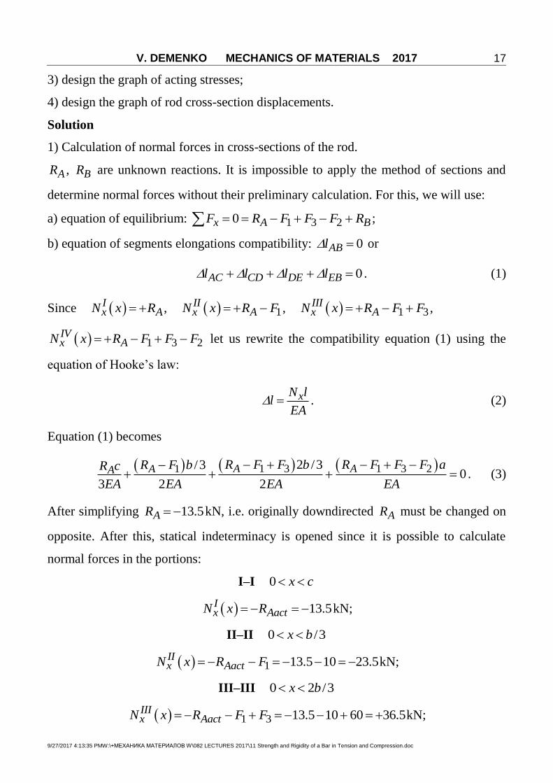
3) design the graph of acting stresses;
4) design the graph of rod cross-section displacements.
Solution
1) Calculation of normal forces in cross-sections of the rod.
AR , BR are unknown reactions. It is impossible to apply the method of sections and
determine normal forces without their preliminary calculation. For this, we will use:
a) equation of equilibrium: 1 3 20x A BF R F F F R ;
b) equation of segments elongations compatibility: 0ABl or
0AC CD DE EBl l l l . (1)
Since Ix AN x R , 1
IIx AN x R F , 1 3
IIIx AN x R F F ,
1 3 2IVx AN x R F F F let us rewrite the compatibility equation (1) using the
equation of Hooke’s law:
xN ll
EA . (2)
Equation (1) becomes
1 3 1 3 21 2 /3/30
3 2 2
A AAA R F F b R F F F aR F bR c
EA EA EA EA. (3)
After simplifying 13.5 AR kN, i.e. originally downdirected AR must be changed on
opposite. After this, statical indeterminacy is opened since it is possible to calculate
normal forces in the portions:
I–I 0 x c
13.5 Ix AactN x R kN;
II–II 0 /3x b
1 13.5 10 23.5 IIx AactN x R F kN;
III–III 0 2 /3x b
1 3 13.5 10 60 36.5 IIIx AactN x R F F kN;

V. DEMENKO MECHANICS OF MATERIALS 2017
9/27/2017 4:13:35 PMW:\+МЕХАНИКА МАТЕРИАЛОВ W\082 LECTURES 2017\11 Strength and Rigidity of a Bar in Tension and Compression.doc
18
IV–IV 0 x a
1 3 2 13.5 10 60 40 3.5 IVx AactN x R F F F kN.
2) Calculation of cross-sectional area A from conditions of strength.
Note, that since ultimate strength of the rod material is different in tension and
compression, we will write the conditions of strength for both most tensile and most
compressed portions.
a) for one tensile portion
34
max max 6
36.5 101.14 10
2 2 2 160 10
III IIItens III x x
ttt t
N NA
A
m
2;
b) since there are three compressed portions in this rod it is necessary to determine
preliminary the most compressed one comparing two relations
3 323.5 10 11.75 10
2 2
IIII xN
A A A
and
33.5 10IVIV xN
A A
we found that second portion is critical in compression since
3 311.75 10 3.5 10
A A
.
In result, for the most compressed part of the rod
34
max max 4
23.5 100.588 10
2 2 2 200 10
II IIcomp II x x
ccc c
N NA
A
m
2.
Comparing two values 40.588 10 cA m2 and 41.14 10 tA m
2 we select the larger
one: 41.14 10 A m2.
3) Calculation in actual stresses in the portions of the rod:
3
4
13.5 1039.47MPa
3 3 1.14 10
II xx c
N
A ,
3
4
23.5 10103.07MPa
2 2 1.14 10
IIII xx c
N
A ,

V. DEMENKO MECHANICS OF MATERIALS 2017
9/27/2017 4:13:35 PMW:\+МЕХАНИКА МАТЕРИАЛОВ W\082 LECTURES 2017\11 Strength and Rigidity of a Bar in Tension and Compression.doc
19
3
4
36.5 10160MPa
2 2 1.14 10
IIIIII xx t
N
A ,
V 3
4
3.5 1030.7MPa
1.14 10
IIV xx c
N
A .
The results show that the rod is strong since all its parts are strong.
4) Determination of the rod elongations.
To solve this problem, we will use the following formula:
xN xl x kx
EA i.e. the elongation is the binear function of the segment length
Let us begin determining the displacements of the portions boundaries (points C, D, E)
calculating corresponding segments elongations. In this, we will use point A as the
origin. Corresponding displacements are
Fig. 23

V. DEMENKO MECHANICS OF MATERIALS 2017
9/27/2017 4:13:35 PMW:\+МЕХАНИКА МАТЕРИАЛОВ W\082 LECTURES 2017\11 Strength and Rigidity of a Bar in Tension and Compression.doc
20
33
. 11 4
13.5 10 50.987 10
3 3 2 10 1.14 10
Ix
p C ACN c
lEA
m,
3 3. 0.987 10 0.987 10
3 2
IIx
p D AD AC CDN b
l l lEA
33 3 3
11 4
23.5 10 40.987 10 0.687 10 1.674 10
3 2 2 10 1.14 10
m,
3 3.
21.674 10 1.674 10
3 2
IIIx
p E AE AD DEN b
l l lEA
33 3 3
11 4
36.5 10 2 41.674 10 2.135 10 0.461 10
3 2 2 10 1.14 10
m,
3 3. 0.461 10 0.461 10
IVx
p B AB AE EBN a
l l lEA
33 3
11 4
3.5 10 30.461 10 0.461 10 0
2 10 1.14 10
.
Note, that the elongation of AB-segment is 0 since it is fixed between two absolutely
rigid supports.
Example 6 Problem of assembly stresses
Fig. 24
When assembling a bar system (Fig. 24) it was found that there were
inaccuracies in the length of the bars ( is inaccuracy in the length of the first bar).

V. DEMENKO MECHANICS OF MATERIALS 2017
9/27/2017 4:13:35 PMW:\+МЕХАНИКА МАТЕРИАЛОВ W\082 LECTURES 2017\11 Strength and Rigidity of a Bar in Tension and Compression.doc
21
During assembly, the bar (1) was put into place by connecting the hinges C and C' to
one point.
It is necessary to determine the forces in the bars after assembly, i.e. when the
bar axis becomes equal to AC''.
We have four unknown forces IR , IIR , vR , hR and three equations of
equilibrium, which are not enough for determining internal forces in two elastic
supporting rods ( IR , IIR ). Consequently, the system is singly statically indeterminate.
Suppose that after assembly the hinge C has moved downward through a distance
Il (real elongation of the first rod) and took position C'', and the hinge B has moved
upward to B'' (B'''B is really shortening of this rod IIl ).
From the condition of equilibrium
0 AM : 2 0 I IIR a R a , 2II IR R .
Compatibility equation is
| | 22
| |
I
II
l a
al
, (*)
where
I II N l
lEA
; II II
II N ll
EA , I IN R , II IIN R .
Then
2
I
II
R l
EA
R l
EA
, 2
I
II
EA R l
R l
, 2 4I II IEA R l R l R l ;
1
5
I EAR
l
,
2
5
II EAR
l
;
I IxN x R , II II
xN x R .
It should be noted that relation (*) connects moduli of the displacements.

V. DEMENKO MECHANICS OF MATERIALS 2017
9/27/2017 4:13:35 PMW:\+МЕХАНИКА МАТЕРИАЛОВ W\082 LECTURES 2017\11 Strength and Rigidity of a Bar in Tension and Compression.doc
22
7 Examples of engineering problems solution
Example 7 Stress analysis of tubular post with round core
A solid circular steel cylinder S is encased in a hollow circular copper tube C (Figs. 25a
and 25b). The cylinder and tube are compressed between the rigid plates of a testing
machine by compressive forces P. The steel cylinder has cross-sectional area sA and
modulus of elasticity sE , the copper tube has area cA and modulus cE , and both parts
have length L.
Determine the following quantities: (a) the compressive normal forces sN in the steel
cylinder and cN in the copper tube; (b) the corresponding compressive stresses s and
c and (c) the shortening of the assembly.
Solution (a) Compressive forces in the steel cylinder and copper tube. We begin by
removing the upper plate of the assembly in order to expose the compressive forces sP
and cP acting on the steel cylinder and copper tube, respectively (Fig. 25c). The normal
force x sN P is the resultant of the uniformly distributed stresses acting over the cross
section of the steel cylinder, and the normal force c cN P is the resultant of the
stresses acting over the cross section of the copper tube.
Equation of equilibrium. A free-body diagram of the upper plate is shown in Fig. 22d.
This plate is subjected to the force P and to the unknown compressive forces sP and
cP ; thus, the equation of equilibrium is
0vertF , 0s cP P P . (1)
Fig. 25 Analysis of a statically indeterminate structure

V. DEMENKO MECHANICS OF MATERIALS 2017
9/27/2017 4:13:35 PMW:\+МЕХАНИКА МАТЕРИАЛОВ W\082 LECTURES 2017\11 Strength and Rigidity of a Bar in Tension and Compression.doc
23
This equation, which is the only nontrivial equilibrium equation available, contains two
unknowns. Therefore, we conclude that the structure is statically indeterminate.
Equation of compatibility. Because the end plates are rigid, the steel cylinder and
copper tube must shorten by the same amount. Denoting the shortenings of the steel
and copper parts by s and c , respectively, we obtain the following equation of
compatibility:
s c (2)
Force-displacement relations. The changes in lengths of the cylinder and tube can be
obtained from the general equation / xN L EA . Therefore, in this example the force-
displacement relations are
ss
s s
P L
E A , c
cc c
P L
E A since s sP N and c cP N . (3, 4)
Substituting these relations into the equation of compatibility (Eq. 2) gives
s c
s s c c
P P
E A E A (5)
This equation gives the compatibility condition in terms of the unknown forces.
Solution of equations. We now solve simultaneously the equations of equilibrium and
compatibility (Eqs. 1 and 5) and obtain the axial forces in the steel cylinder and copper
tube:
s ss
s s c c
E AP P
E A E A
, c c
cs s c c
E AP P
E A E A
. (6, 7)
These equations show that the compressive forces in the steel and copper parts are
directly proportional to their respective axial rigidities and inversely proportional to the
sum of their rigidities.
(b) Compressive stresses in the steel cylinder and copper tube. Knowing the axial
internal forces, we can now obtain the compressive stresses in the two materials:

V. DEMENKO MECHANICS OF MATERIALS 2017
9/27/2017 4:13:35 PMW:\+МЕХАНИКА МАТЕРИАЛОВ W\082 LECTURES 2017\11 Strength and Rigidity of a Bar in Tension and Compression.doc
24
s ss
s s s c c
N PE
A E A E A
, c c
cc s s c c
N PE
A E A E A
. (8, 9)
Note that the stresses are proportional to the moduli of elasticity of the respective
materials. Therefore, the "stiffer" material has the larger stress.
(c) Shortening of the assembly. The shortening of the entire assembly can be
obtained from either Eq. (3) or Eq. (4). Thus, upon substituting the forces (from Eqs. 6
and 7), we get
s c
s s c c s s c c
P L P L PL
E A E A E A E A
(10)
This result shows that the shortening of the assembly is equal to the total load divided
by the sum of the stiffness of the two parts.
Example 8 Analysis of a statically indeterminate structure with absolutely
rigid element
A horizontal rigid bar AB is pinned at end A and supported by two wires (CD and EF)
at points D and F (Fig. 26a). A vertical load P acts at end B of the bar. The bar has
length 3b and wires CD and EF have lengths 1L and 2L , respectively. Also, wire CD
has diameter 1d and modulus of elasticity 1E , wire EF has diameter 2d and modulus
2E .
(a) Obtain formulas for the allowable load P if the allowable stresses in wires CD and
EF, respectively, are 1 and 2 . (Disregard the weight of the bar itself).
(b) Calculate the allowable load P for the following conditions: wire CD is made of
aluminum with modulus 1 72E GPa, diameter 1 4.0d mm, and length 1 0.40L m.
Wire EF is made of magnesium with modulus 2 45E GPa, diameter 2 3.0d mm, and
length 2 0.30L m. The allowable stresses in the aluminum and magnesium wires are
1 200 MPa and 2 175 MPa, respectively.

V. DEMENKO MECHANICS OF MATERIALS 2017
9/27/2017 4:13:35 PMW:\+МЕХАНИКА МАТЕРИАЛОВ W\082 LECTURES 2017\11 Strength and Rigidity of a Bar in Tension and Compression.doc
25
Solution Equations of equilibrium. We
begin the analysis by drawing a free-
body diagram of bar AB (Fig. 26b). In
this diagram 1T and 2T are the unknown
tensile forces in the wires and HR and
VR are the horizontal and vertical
components of the reaction at the
support. The structure is statically
indeterminate because there are four
unknown forces ( 1T , 2T , HR , and VR )
but only three independent equations of
equilibrium. Taking moments about point
A (with counterclockwise moments being
positive) yields
0AM ,
1 2 2 3 0T b T b P b or 1 22 3T T P . (1)
The other two equations, obtained by summing forces in the horizontal direction and
summing forces in the vertical direction, are of no benefit in finding 1T and 2T .
Equation of compatibility. To obtain an equation pertaining to the displacements, we
observe that the load P causes bar AB to rotate about the pin support at A, thereby
stretching the wires. The resulting displacements are shown in the displacement
diagram of Fig. 26c, where line AB represents the original position of the rigid bar and
line AB' represents the rotated position. The displacements 1 and 2 are the
elongations of the wires. Because these displacements are very small, the bar rotates
Fig. 26 Analysis of a statically indeterminate
structure

V. DEMENKO MECHANICS OF MATERIALS 2017
9/27/2017 4:13:35 PMW:\+МЕХАНИКА МАТЕРИАЛОВ W\082 LECTURES 2017\11 Strength and Rigidity of a Bar in Tension and Compression.doc
26
through a very small angle (shown highly exaggerated in the figure) and we can make
calculations on the assumption that points D, F, and B move vertically downward
(instead of moving along the arcs of circles).
Because the horizontal distances AD and DF are equal, we obtain the following
geometric relationship between the elongations:
2 12 . (2)
Equation (2) is the equation of compatibility.
Force-displacement relations. Since the wires behave in a linearly elastic manner, their
elongations can be expressed in terms of the unknown forces 1T and 2T by means of
the following expressions:
1 11
1 1
T L
E A , 2 2
22 2
T L
E A ,
in which 1A and 2A are the cross-sectional areas of wires CD and EF, respectively; that
is,
21
14
dA
,
22
24
dA
.
For convenience in writing equations, let us introduce the following notation for
the flexibilities of the wires:
11
1 1
Lf
E A , 2
22 2
Lf
E A . (3, 4)
Then the force-displacement relations become
1 1 1f T , 2 2 2f T . (5)
Substituting these expressions into the equation of compatibility (Eq. 1) gives

V. DEMENKO MECHANICS OF MATERIALS 2017
9/27/2017 4:13:35 PMW:\+МЕХАНИКА МАТЕРИАЛОВ W\082 LECTURES 2017\11 Strength and Rigidity of a Bar in Tension and Compression.doc
27
2 2 1 12f T f T . (6)
We now have expressed the equation of compatibility in terms of the unknown forces.
Solution of equations. The equation of equilibrium (Eq. 1) and the equation of
compatibility (Eq. 6) each contain the forces 1T and 2T as unknown quantities. Solving
the two equations simultaneously yields
21
1 2
3
4
f PT
f f
, 1
21 2
6
4
f PT
f f
. (7, 8)
Knowing the forces 1T and 2T , we can easily find the elongations of the wires from the
force-displacement relations.
(a) Allowable load P. Now that the statically indeterminate analysis is completed and
the forces in the wires are known, we can determine the permissible value of the load P.
The stress 1 in wire CD and the stress 2 in wire EF are readily obtained from the
forces (Eqs. 7 and 8):
1 21
1 1 1 2
3
4
T P f
A A f f
, 2 1
22 2 1 2
6
4
T P f
A A f f
. (9, 10)
From the first of these equations we solve for the permissible force 1P , based upon the
allowable stress 1 in the aluminum wire:
1 1 1 21
2
4
3
A f fP
f
. (11)
Similarly, from the second equation we get the permissible force 2P based upon the
allowable stress 2 in the magnesium wire:
2 2 1 22
1
4
6
A f fP
f
. (12)

V. DEMENKO MECHANICS OF MATERIALS 2017
9/27/2017 4:13:35 PMW:\+МЕХАНИКА МАТЕРИАЛОВ W\082 LECTURES 2017\11 Strength and Rigidity of a Bar in Tension and Compression.doc
28
The smaller of these two values of the load is the maximum allowable load [P].
(b) Numerical calculations for the allowable load. Using the given data and the
preceding equations, we obtain following numerical values:
22
211
4.0mm12.57mm
4 4
dA
,
22
222
3.0mm7.069mm
4 4
dA
,
611 2
1 1
0.40m0.4420 10 m/N
(72GPa)(12.57mm )
Lf
E A
,
622 2
2 2
0.30m0.9431 10 m/N
(45GPa)(7.069mm )
Lf
E A
.
Also, the allowable stresses are
1 200 MPa, 2 175 MPa.
Therefore, substituting into Eqs. (11) and (12) gives
1 2.41P kN, 2 1.26P kN.
The first result is based upon the allowable stress 1 in the aluminum wire and the
second is based upon the allowable stress 2 the magnesium wire. The allowable load
is the smaller of the two values:
[ ] 1.26P kN.
At this load the stress in the magnesium is 175 MPa (the allowable stress) and the stress
in the aluminum is (1.26/ 2.41)(200MPa) 105 MPa. As expected, this stress is less
than the allowable stress of 200 MPa.

V. DEMENKO MECHANICS OF MATERIALS 2017
9/27/2017 4:13:35 PMW:\+МЕХАНИКА МАТЕРИАЛОВ W\082 LECTURES 2017\11 Strength and Rigidity of a Bar in Tension and Compression.doc
29
Example 9 Calculation of internal forces in statically indeterminate rod
system with absolutely rigid element
A horizontal rigid bar ADB of length
2b is pinned to a support at A and held
by two inclined wires CD and CB
(Fig. 27a). The wires are attached to a
support at point C, which is located at
a vertical distance b above point A.
Both wires are made of the same
material and have the same diameter.
Determine the tensile forces 1T and 2T
in wires CD and CB, respectively, due
to the vertical load P acting at the end
of the bar.
Solution Equation of equilibrium. A
free-body diagram of bar AB (Fig. 24b)
shows that there are four unknown
forces, namely, the tensile forces 1T
and 2T in the wires and the two
reaction components ( HR and VR ) at
the pin support. Since there are only
three independent equations of
equilibrium, the structure is singly
statically indeterminate. We can obtain
an equation of equilibrium containing
only 1T and 2T as unknowns by
summing moments about point A:
0AM ,
Fig. 27 Analysis of a statically indeterminate
structure

V. DEMENKO MECHANICS OF MATERIALS 2017
9/27/2017 4:13:35 PMW:\+МЕХАНИКА МАТЕРИАЛОВ W\082 LECTURES 2017\11 Strength and Rigidity of a Bar in Tension and Compression.doc
30
1 1 2 2sin 2 sin 2 0 bT bT bP (1)
in which 1 and 2 are the angles between the wires and the bar.
From the geometry of the structure (Fig. 27a) we see that
11
sin2 2
CA b
CD b ,
21
sin5 5
CA b
CB b . (2)
Substituting these values into Eq. (1) and rearranging, we get
1 222
2 5
T TP (3)
which is the final form of the equation of equilibrium.
Equation of compatibility. An equation of compatibility can be obtained by considering
the displacements of points D and B. For this purpose, we draw the displacement
diagram shown in Fig. 27c. Line AB represents the original position of bar AB and line
AB' represents the rotated position. Since the angle of rotation of bar AB is very small,
the displacements 1 and 2 of points D and B, respectively, can be treated as small
vertical displacements. Because the distance from A to B is twice the distance from A to
D, we see that
2 12 (4)
which is the equation of compatibility.
Force-displacement relations. Now we need to relate the forces 1T and 2T in the wires
to the vertical displacements 1 and 2 at points D and B, respectively. Let us begin by
considering wire CD, which rotates from its original position CD to its final position
CD' (Fig. 27c). We draw a perpendicular DD'' from point D to line CD'. Because the
displacements and angle changes are very small, we can assume that the distance CD''
is equal in length to the distance CD. (That is, a circular arc DD'' with point C as its
center is indistinguishable from the perpendicular line DD''.)

V. DEMENKO MECHANICS OF MATERIALS 2017
9/27/2017 4:13:35 PMW:\+МЕХАНИКА МАТЕРИАЛОВ W\082 LECTURES 2017\11 Strength and Rigidity of a Bar in Tension and Compression.doc
31
The displacement triangle DD'D'' in Fig. 27c is redrawn for clarity in Fig. 27d.
The distance DD' is the vertical displacement 1 of point D and the distance D'D'' is the
elongation СD of wire CD. The angle 1 appears in the triangle as angle DD'D''. To
prove this, we note that line DD' is perpendicular to line AB, and line DD'' is
perpendicular to line CD (for small angles of rotation). Therefore, from the
displacement triangle DD'D'' we get
11 1sin
2CD
. (5)
This equation provides the geometric relation between the elongation of wire CD and
the downward displacement of point D.
The elongation СD of wire CD is related to the force in the wire by the following
force-displacement relation:
1 1 2CDCD
T L T b
EA EA (6)
in which 2CDL b , is the length of wire CD. Combining the last two equations for
CD , we get
11
2bT
EA . (7)
In a similar manner, we can relate the displacement 2 to the elongation CB of wire
CB (see Fig. 27e) and obtain
22
5bT
EA . (8)
Equations (7) and (8) are the force-displacement relations that give the displacements
of points D and B in terms of the unknown forces in the wires.
Substituting 1 and 2 from the force-displacement relations into the equation of
compatibility (Eq. 4) yields
2 15 4T T (9)

V. DEMENKO MECHANICS OF MATERIALS 2017
9/27/2017 4:13:35 PMW:\+МЕХАНИКА МАТЕРИАЛОВ W\082 LECTURES 2017\11 Strength and Rigidity of a Bar in Tension and Compression.doc
32
which is the equation of compatibility in terms of the unknown forces.
Solution of equations. As the final step in this example we solve simultaneously the
equation of equilibrium (Eq. 3) and the equation of compatibility (Eq. 9). The results
are
110 10
1.4068 2 5 5
PT P
, 1
24
1,1255
TT P . (10, 11)
Thus, we have found the tensile forces in the wires by solving the statically
indeterminate structure.
Knowing the tensile forces in the wires, we can easily determine all other force
and displacement quantities. For instance, the reactions at support A can be found from
equilibrium equations and the displacements 1 and 2 can be found from Eqs. (7) and
(8).
Note: In this example, the final solution for the forces does not involve the axial
rigidity EA of the wires. (This fact is readily apparent in a symbolic solution but might
escape notice in a numerical solution.) The reason is that both wires have the same
axial rigidity, and therefore EA cancels out of the solution. If each wire had a different
rigidity, the rigidities would appear in the final expressions.
Example 10 Thermal effects in statically indeterminate rod systems
A sleeve in the form of a circular tube of length L is placed around a bolt and fitted
between washers at each end (Fig. 28a). The nut is then turned until it is just snug. The
sleeve and bolt are made of different materials and have different cross-sectional areas.
(a) If the temperature of the entire assembly is raised by an amount T , what stresses
s and b are developed in the sleeve and bolt, respectively? (b) What is the increase
in the length L of the sleeve and bolt? (Assume that the coefficient of thermal
expansion s of the sleeve is greater than the coefficient b of the bolt).
Solution Because the sleeve and bolt are of different materials, they will elongate by
different amounts when heated and allowed to expand freely. However, when they are
held together by the assembly, free expansion cannot occur and thermal stresses are

V. DEMENKO MECHANICS OF MATERIALS 2017
9/27/2017 4:13:35 PMW:\+МЕХАНИКА МАТЕРИАЛОВ W\082 LECTURES 2017\11 Strength and Rigidity of a Bar in Tension and Compression.doc
33
developed in both materials. To find these stresses, we use the same concepts as in any
statically indeterminate analysis – equilibrium equations, compatibility equations, and
displacement relations. However, we cannot formulate these equations until we
disassemble the structure.
A simple way to cut the structure is to remove the head of the bolt, thereby allowing the
sleeve and bolt to expand freely under the temperature change T (Fig. 28b). The
resulting elongations of the sleeve and bolt are denoted 1 and 2 , respectively, and the
corresponding temperature-displacement relations are
1 ( )s T L , 2 ( )b T L . (1)
Since s is greater than b , the elongation 1 is greater than 2 , as shown in Fig. 28b.
The axial forces in the sleeve and bolt must be such that they shorten the sleeve
and stretch the bolt until the final lengths of the sleeve and bolt are the same. These
forces are shown in Fig. 28c, where sP denotes the compressive force in the sleeve and
bP denotes the tensile force in the bolt. The corresponding shortening 3 of the sleeve
and elongation 4 of the bolt are
3s
s s
P L
E A , 4
b
b b
P L
E A (2)
in which s sE A and b bE A are the respective axial rigidities. Equations (2) are the load-
displacement relations.
Now we can write an equation of compatibility expressing the fact that the final
elongation is the same for both the sleeve and the bolt. The elongation of the sleeve
is 1 3 and of the bolt is 2 4 ; therefore,
1 3 2 4 . (3)
Substituting the temperature-displacement and load-displacement relations (Eqs. 1 and
2) into this equation gives
( ) ( )s bs b
s s b b
P L P LT L T L
E A E A (4)

V. DEMENKO MECHANICS OF MATERIALS 2017
9/27/2017 4:13:35 PMW:\+МЕХАНИКА МАТЕРИАЛОВ W\082 LECTURES 2017\11 Strength and Rigidity of a Bar in Tension and Compression.doc
34
from which we get
( ) ( )s bs b
s s b b
P L P LT L T L
E A E A , (5)
which is the final form of the compatibility equation. Note that it contains the forces sP
and bP as unknowns.
An equation of equilibrium is obtained from Fig. 28c, which is a free-body
diagram of the part of the assembly remaining after the head of the bolt is removed.
Summing forces in the horizontal direction gives
s bP P (6)
which expresses the obvious fact that the compressive force in the sleeve is equal to the
tensile force in the bolt.
Fig. 28 Sleeve and bolt assembly with uniform temperature increase T

V. DEMENKO MECHANICS OF MATERIALS 2017
9/27/2017 4:13:35 PMW:\+МЕХАНИКА МАТЕРИАЛОВ W\082 LECTURES 2017\11 Strength and Rigidity of a Bar in Tension and Compression.doc
35
We now solve simultaneously the equations of compatibility and equilibrium
(Eqs. 5 and 6) and obtain the axial forces in the sleeve and bolt:
( )( )s b s s b bs b
s s b b
T E A E AP P
E A E A
. (7)
When deriving this equation, we assumed that the temperature increased and that the
coefficient s was greater than the coefficient b . Under these conditions, sP is the
compressive force in the sleeve and bP is the tensile force in the bolt.
The results will be quite different if the temperature increases but the coefficient
s is less than the coefficient b . Under these conditions, a gap will open between the
bolt head and the sleeve and there will be no stresses in either part of the assembly.
(a) Stresses in the sleeve and bolt. Expressions for the stresses s and b in the sleeve
and bolt, respectively, are obtained by dividing the corresponding forces by the
appropriate areas:
( )( )s s b s b bs
s s s b b
P T E E A
A E A E A
, (8)
s b s b sbb
b s s b b
T E E AP
A E A E A
. (9)
Under the assumed conditions, the stress s in the sleeve is compressive and the stress
b in the bolt is tensile. It is interesting to note that these stresses are independent of
the length of the assembly and their magnitudes are inversely proportional to their
respective areas (that is, / /s b b sA A ).
(b) Increase in length of the sleeve and bolt. The elongation of the assembly can be
found by substituting either sP or bP from Eq. (7) into Eq. (4), yielding
( )( )s s s b b b
s s b b
E A E A T L
E A E A
. (10)
With the preceding formulas available, we can readily calculate the forces, stresses, and
displacements of the assembly for any given set of numerical data. Note: As a partial

V. DEMENKO MECHANICS OF MATERIALS 2017
9/27/2017 4:13:35 PMW:\+МЕХАНИКА МАТЕРИАЛОВ W\082 LECTURES 2017\11 Strength and Rigidity of a Bar in Tension and Compression.doc
36
check on the results, we can see if Eqs. (7), (8), and (10) reduce to known values in
simplified cases. For instance, suppose that the bolt is rigid and therefore unaffected by
temperature changes. We can represent this situation by setting 0b and letting bE
become infinitely large, thereby creating an assembly in which the sleeve is held
between rigid supports. Substituting the stated values of b and bE into Eqs. (7), (8),
and (10), we find
( )s s s sP E A T , ( )s s sE T , 0 .
As a second special case, suppose that the sleeve and bolt are made of the same
material. Then both parts will expand freely and will lengthen the same amount when
the temperature changes. No forces or stresses will be developed. To see if the derived
equations predict this behavior, we will assume that both parts have properties , E,
and A. Substituting these values into Eqs. (7 – 10) we get
0s bP P , 0s b , ( )T L ,
which are the expected results.
As a third special case, suppose we remove the sleeve so that only the bolt
remains. The bolt is then free to expand and no forces or stresses will develop. We can
represent this case by setting 0sA in Eqs. (7), (9), and (10), which then gives
0bP , 0b , ( )b T L .
8 Examples of statically indeterminate rod systems
Fig. 29 Fig. 30

V. DEMENKO MECHANICS OF MATERIALS 2017
9/27/2017 4:13:35 PMW:\+МЕХАНИКА МАТЕРИАЛОВ W\082 LECTURES 2017\11 Strength and Rigidity of a Bar in Tension and Compression.doc
37
Fig. 31 Fig. 32
Fig. 33 Fig. 34
Fig. 35 Fig. 36

V. DEMENKO MECHANICS OF MATERIALS 2017
9/27/2017 4:13:35 PMW:\+МЕХАНИКА МАТЕРИАЛОВ W\082 LECTURES 2017\11 Strength and Rigidity of a Bar in Tension and Compression.doc
38
Fig. 37 Fig. 38
Fig. 39 Fig. 40
Fig. 41 Fig. 42

V. DEMENKO MECHANICS OF MATERIALS 2017
9/27/2017 4:13:35 PMW:\+МЕХАНИКА МАТЕРИАЛОВ W\082 LECTURES 2017\11 Strength and Rigidity of a Bar in Tension and Compression.doc
39
Fig. 43 Fig. 44
Fig. 45 Fig. 46

MINISTRY OF EDUCATION AND SCIENCE OF UKRAINE
National aerospace university “Kharkiv Aviation Institute”
Department of aircraft strength
Course Mechanics of materials and structures
HOME PROBLEM 7
Design problem for statically indeterminate rod in tension-compression
Name of student:
Group:
Advisor:
Data of submission:
Mark:
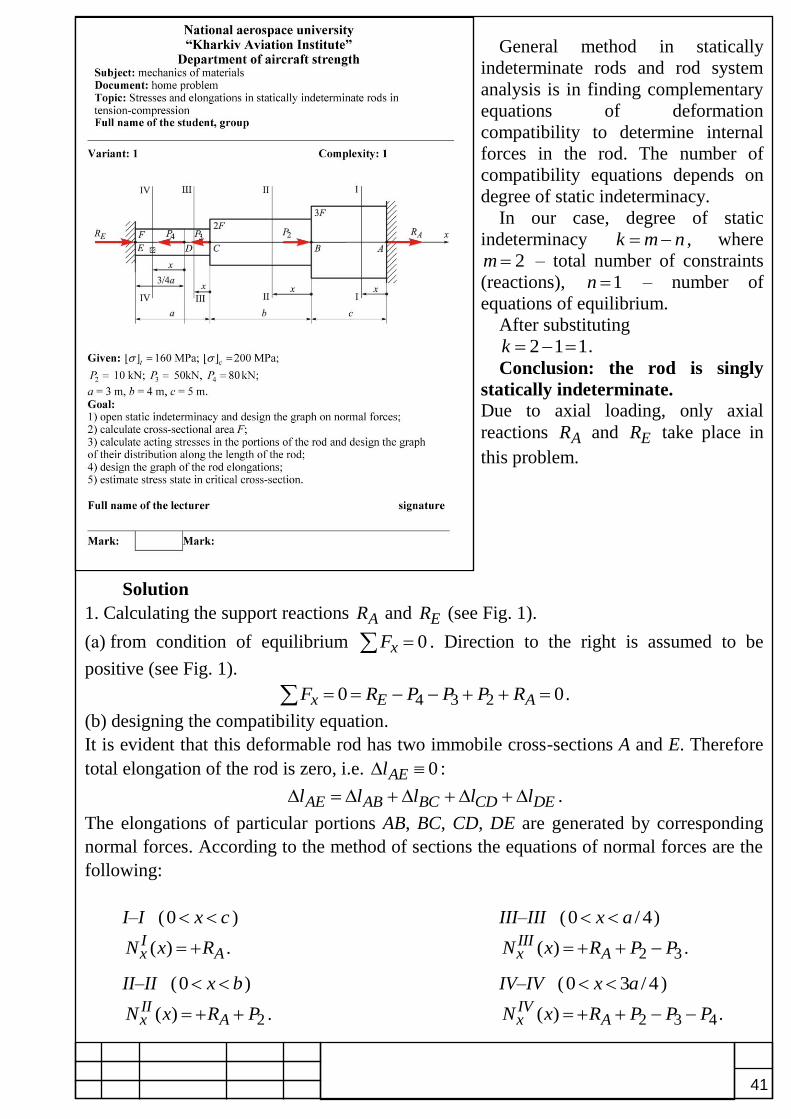
41
General method in statically
indeterminate rods and rod system
analysis is in finding complementary
equations of deformation
compatibility to determine internal
forces in the rod. The number of
compatibility equations depends on
degree of static indeterminacy.
In our case, degree of static
indeterminacy k m n , where
2m – total number of constraints
(reactions), 1n – number of
equations of equilibrium.
After substituting
2 1 1k .
Conclusion: the rod is singly
statically indeterminate.
Due to axial loading, only axial
reactions AR and ER take place in
this problem.
Solution
1. Calculating the support reactions AR and ER (see Fig. 1).
(а) from condition of equilibrium 0xF . Direction to the right is assumed to be
positive (see Fig. 1).
4 3 20 0x E AF R P P P R .
(b) designing the compatibility equation.
It is evident that this deformable rod has two immobile cross-sections A and E. Therefore
total elongation of the rod is zero, i.e. 0AEl :
AE AB BC CD DEl l l l l .
The elongations of particular portions AB, BC, CD, DE are generated by corresponding
normal forces. According to the method of sections the equations of normal forces are the
following:
I–I (0 x c ) III–III (0 / 4x a )
( )Ix AN x R . 2 3( )III
x AN x R P P .
II–II (0 x b ) IV–IV (0 3 / 4x a )
2( )IIx AN x R P . 2 3 4( )IV
x AN x R P P P .

42
Fig. 1

43
Corresponding elongations of the portions are:
( )( )
3
Ix
ABN x c
lAE
; ( )( )
2
IIx
BCN x b
lAE
;
1( )
4
IIIx
CD
N x a
lAE
;
3( )
4
IVx
DE
N x a
lAE
;
2 2 3 2 3 45 3 9
2( ) ( ) ( ) 03 4 4
A A A AR R P R P P R P P P
2 3 43360
80 60 36 27 600 1800 2160 3360 4280
A AR P P P R kN.
"+" sign of AR reaction supports the conclusion that AR reaction is actually determined to
the right. After AR finding, static indeterminacy is opened and normal forces may be
determined. 2. Calculating the normal forces in an arbitrary cross-section of each portion.
( ) 42Ix AN x R kN,
2( ) 42 10 52IIx AN x R P kN,
2 3( ) 42 10 50 2IIIx AN x R P P kN,
2 3 4( ) 42 10 50 80 78IVx AN x R P P P kN.
The graph of normal force distribution is shown on Fig. 1.
3. Calculating the cross-sectional area A from condition of strength in critical portion. Due to [ ] [ ]t c , it will be necessary to design two conditions of strength – for critically
tensile and critically compressed portions. In our case, (а) for three tensile portions II-II portion is evidently critical after comparing the relations
42
3A,
52
2A and
2
A. That is why
34 2
max 6
( ) ( ) 52 101.625 10 m
2 2 2 160 10
II IIII x x
t x t tt t
N x N xA
A
;
(b) for compressed portion:
34 2
max 6
( ) ( ) 78 103.9 10 m
200 10
IVIVxIV x
c x ссc с
N x N xA
A
.
For future calculating, we should select larger of two cross-sectional areas which will
satisfy both conditions of strength: 4 2
max 3.9 10 mсA A .
4. Calculating the acting stresses. 3
4max
( ) 42 1035.9
3 3 3.9 10
II xx
N x
A
MPa,
3
4max
( ) 52 1066.7
2 2 3.9 10
IIII xx
N x
A
MPa,

44
3
4max
( ) 2 105.1
3.9 10
IIIIII xx
N x
A
MPa,
3
4max
( ) 78 10200.0 MPa
3.9 10
IVIV xx
N x
A
.
Graph of stress distribution is shown on Fig. 1.
5. Analysis of stress state type in an arbitrary point K of critical section.
IV3 200 MPa,x
1 2 0.
Fig. 2
Conclusion: stress state is uniaxial, deformation is tension.
6. Drawing the graph of displacements. E point is selected as the origin. The displacements of particular points are designated by . Therefore, 0E . Due to Hook's law, the displacement function is linear, that is why
the displacements of each portion tip are numerically equal to the portion elongation or
shortening. Elasticity modulus value 112 10 PaE is used in this calculation.
3
411 4
max
( )3 78 10 3 322.5 10 m 2.25 mm
4 4 2 10 3.9 10
IVx
D EDN x a
lEA
.
4 4
max
( )22.5 10 22.5 10
4
IIIx
C EC ED DCN x a
l l lEA
34 4 4
11 4
2 10 322.5 10 0.19 10 22.31 10 m 2.23 mm
4 2 10 3.9 10
.
4 4
max
( )22.31 10 22.31 10
2
IIx
B EB EC CBN x b
l l lEA
3
4 4 411 4
52 10 422.31 10 13.33 10 8.98 10 m 0.898 mm
2 2 10 3.9 10
.
4 4
max
( )8.98 10 8.98 10
3
Ix
A EA EB BAN x c
l l lEA
3
4 4 411 4
42 10 58.98 10 8.97 10 0.01 10 m
3 2 10 3.9 10
.
Let us estimate the error of calculating, since really the displacement of A point must be zero according to compatibility equation:
4
4
0.01 10100% 0.11%
8.97 10
.
Due to negligibly little error, the calculation is true. The graph of displacements is also shown on Fig. 1.
point K
Remaining principal stresses are: