b-fields at nif workshop
TRANSCRIPT
LLNL-PRES-6788211
B-fields at NIF Workshop
• The workshop's charter is to capture the near term requirements for implementing researchers’ plans for magnetic fields around targets, and to explore longer term, strategic needs.
• The workshop’s charge is to document those near term and long-term requirements in the materials that come out of the presentations and discussions.

LLNL-PRES-xxxxxx 2
B-fields at NIF Workshop format
• Day 1 – talks focused on ICF applications • Day 2 – talks focused around discovery science proposals
• All talks are to be kept short and informal, with an emphasis on
the implementation of a B-field capability around a target rather than a deep dive into the interesting physics
• Significant amounts of time have been left unstructured for discussion following small sets of the talks
The viewgraphs submitted (hopefully on the requested template) will comprise the proceedings - notes and action items will be captured and relayed to the NIF director

LLNL-PRES-xxxxxx 3
B-fields at NIF Workshop day 1
Monday, 10/12
1300 - Introduction - Mark Herrmann/Doug Larson 1310 - Welcome - Ground rules - Kevin Fournier/John Moody
1315 - 01-ICF needs - Perkins et al. - Ignition Applications
1345 - discussion - ICF requirements re. impact on ICF
1415 - 02-ICF continued - hohlraum performance, LPI supression - D. Strozzi (LLNL), D. Montgomery (LANL) 1445 - ICF requirements/discussion re. NIF implementation
1515 - break
1530 - 03-X-Ray Sources - Kemp (Colvin to present) (LLNL)
1550 - 04-MagLIF - Adam Sefkow (SNL)
1620 - requirements re. laser-heated plasmas/discussion of NIF implementation 1650 - 05-Direct Drive: PDD and Shock Ignition - Hohenberger (LLE)
1710 - 06-MIFEDS at OMEGA - G. Fiksel (LLE)
1740 - discussion re. implementation issues
1810 - 07-FACILITY AND MACHINE SAFETY ISSUES - VanWonterghem/Kalantar
1840 - Day 1 report out - VanWonterghem/Fournier
1900 - adjourn
LLNL-PRES-xxxxxx 4
B-fields at NIF Workshop day 2
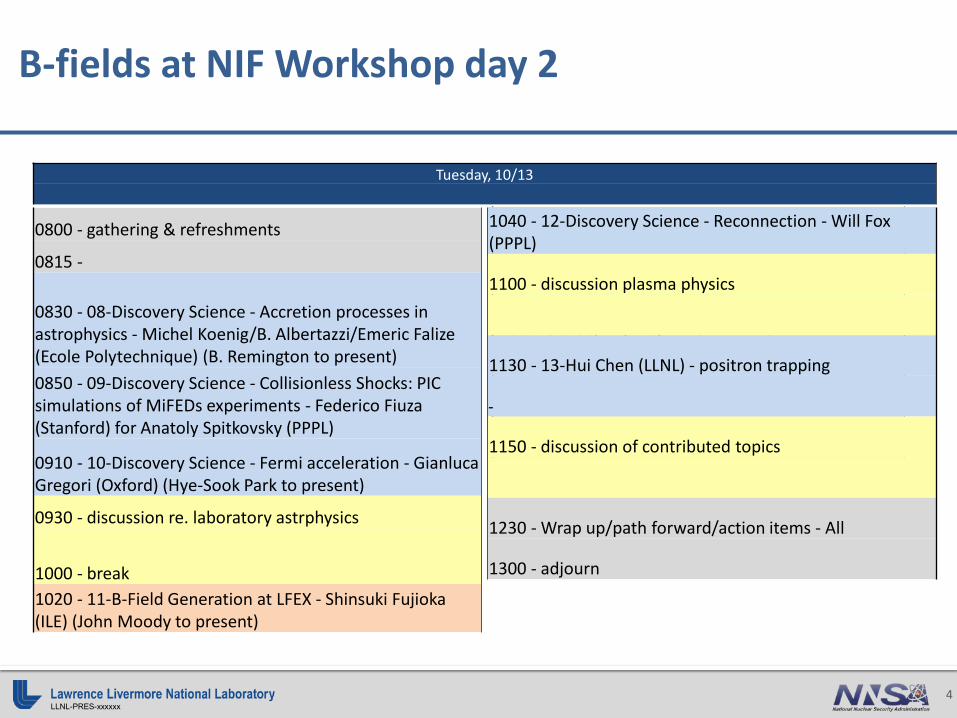
Tuesday, 10/13
0800 - gathering & refreshments
0815 -
0830 - 08-Discovery Science - Accretion processes in astrophysics - Michel Koenig/B. Albertazzi/Emeric Falize (Ecole Polytechnique) (B. Remington to present) 0850 - 09-Discovery Science - Collisionless Shocks: PIC simulations of MiFEDs experiments - Federico Fiuza (Stanford) for Anatoly Spitkovsky (PPPL)
0910 - 10-Discovery Science - Fermi acceleration - Gianluca Gregori (Oxford) (Hye-Sook Park to present)
0930 - discussion re. laboratory astrphysics
1000 - break 1020 - 11-B-Field Generation at LFEX - Shinsuki Fujioka (ILE) (John Moody to present)
1040 - 12-Discovery Science - Reconnection - Will Fox (PPPL)
1100 - discussion plasma physics
1130 - 13-Hui Chen (LLNL) - positron trapping
1150 - discussion of contributed topics
1040 - 12-Discovery Science - Reconnection - Will Fox (PPPL)
1100 - discussion plasma physics
1130 - 13-Hui Chen (LLNL) - positron trapping
1150 - discussion of contributed topics
1230 - Wrap up/path forward/action items - All
1300 - adjourn

Basic B-field physics considerations
10/23/2015 2015 NIF B-field Workshop 1
B-field physics considerations
Soak-in time (1D in r)
2015 NIF B-field Workshop
a
a+δa
× B
B=0
For Au, a = 5 mm, δa = 30 µm: τ = 3.9 µs
B-field pressure (1D in r)
a
a+δa
× B
B=0
B-field energy in 1 cm3
Comet
Janus
Gekko Omega
NIF
Hall parameter
ωτ = 1
Experiment(s):
10/11/15% 1%
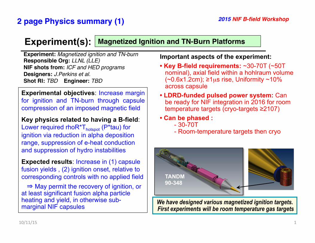
Magnetized Ignition and TN-Burn Platforms!
2015 NIF B-field Workshop!
Experiment: Magnetized ignition and TN-burn!Responsible Org: LLNL (LLE)!NIF shots from: ICF and HED programs!Designers: J.Perkins et al. !Shot RI: TBD Engineer: TBD!
Important aspects of the experiment: • Key B-field requirements: ~30-70T (~50T
nominal), axial field within a hohlraum volume (~0.6x1.2cm); ≥1µs rise, Uniformity ~10% across capsule
• LDRD-funded pulsed power system: Can be ready for NIF integration in 2016 for room temperature targets (cryo-targets ≥2107)
• Can be phased : - 30-70T - Room-temperature targets then cryo
Experimental objectives: Increase margin for ignition and TN-burn through capsule compression of an imposed magnetic field
Key physics related to having a B-field: Lower required rhoR*Thotspot (P*tau) for ignition via reduction in alpha deposition range, suppression of e-heat conduction and suppression of hydro instabilities
Expected results: Increase in (1) capsule fusion yields , (2) ignition onset, relative to corresponding controls with no applied field May permit the recovery of ignition, or at least significant fusion alpha particle heating and yield, in otherwise sub-marginal NIF capsules
2 page Physics summary (1)!
TANDM 90-348
We have designed various magnetized ignition targets. First experiments will be room temperature gas targets
10/11/15% 2%
2 page Physics summary (2)! 2015 NIF B-field Workshop!
Experiment(s): Magnetized Ignition and TN-Burn Platforms!
SECTION A-ASCALE .125
A A
3LLNLHOHLRAUM MODULELEA13-50053512LLNL PULSE POWER SYSTEMLEA13-50053411LLNLZ2, DLP )DIAGOSTIC LOAD PACKAGE) HOUSINGLEA13-5005251
PARTS LISTITEMVENDORDESCRIPTIONPART NUMBERQTY
1
1
2
2
3
3
6
6
7
7
8
8
A A
B B
C C
D D
5 4
5 4
LAWRENCE LIVERMORENATIONAL LABORATORY
LAWRENCE LIVERMORE NATIONAL SECURITY-LLC, P.O. BOX 808 LIVERMORE CA 94551TITLE
SIZE CAGE CODE
14067SCALE
DRAWING NUMBER REV
SHEET OFUSED ON
APPLICATION
DIV/GROUP
ORIGINATOR
DRAWN
CHECKED
APPROVED
APPROVALS DATE
CLASSIFIED BY
CONTRACT NO
UNLESS OTHERWISE SPECIFIEDDIMENSIONS IN INCHES
TOLERANCES ARE:DECIMALS: ± .005 ANGLES: ± 1°
DO NOT SCALE FROM DRAWING
THIS WORK WAS PERFORMED UNDER THE AUSPICES OF THE U.S. DEPARTMENT OF ENERGY UNDERCONTRACT DE-AC52-07NA27344. NEITHER THE UNITED STATES GOVERNMENT NOR LAWRENCELIVERMORE NATIONAL SECURITY, LLC, NOR ANY OF THEIR EMPLOYEES MAKES ANY WARRANTY,
EXPRESSED OR IMPLIED OR ASSUMES ANY LEGAL LIABILITY OR RESPONSIBILITY FOR THEACCURACY, COMPLETENESS OR USEFULNESS OF ANY INFORMATION, APPARATUS, PRODUCT, ORPROCESS DISCLOSED, OR REPRESENTS THAT ITS USE WOULD NOT INFRINGE PRIVATELY OWNED
RIGHTS. REFERENCE HEREIN TO ANY SPECIFIC COMMERCIAL PRODUCT, PROCESS, OR SERVICE BYTRADE NAME, TRADEMARK, MANUFACTURER, OR OTHERWISE DOES NOT NECESSARILY CONSTITUTE ORIMPLY ITS ENDORSEMENT, RECOMMENDATION, OR FAVORING BY THE UNITED STATES GOVERNMENT OR
LAWRENCE LIVERMORE NATIONAL SECURITY, LLC. 2.000
THIRD ANGLE PROJECTION
DLP Z2, WITH HOHLRAUM
LEA13-5005371 1
AA-V1D
HAWKINS4 5/21/2014
RHODES4 5/21/2014
PERKINS3 5/21/2014
NIF MAGNETIZED TARGETPERKINS3
NSED
5/21/2014
A
LDRD
Drawing Template Format:I2013_DRAWING_IVTitle Block Version:011714
PERKINS3
NEXT ASSY
WBS
DRAWING CLASS
C
Beam Research Program
SH
DR
AW
ING
NU
MB
ER
RE
VLE
A13
-500
537-
AA
-V1
1
DR
AW
ING
:LE
A13
-500
537.
idw
MO
DE
L: L
EA
13-5
0053
7.ia
mIN
VE
NT
OR
201
3
LEA13-500537-AA-V1
INCHES [MM]
UNCLASSIFIED
UNCLASSIFIED
CHECK PRINT
CLASSIFICATION: UNCLASSIFIED-LIMITED DISTRIBUTION
6
APPROVEDDRAWN DATEDESCRIPTIONLTRZONE
REVISIONS
/ AA INITIAL RELEASE 5/21/2014HAWKINS4 PERKINS3
CHECKED
RHODES4
Timestamp-5/22/2014 06:43:AM
114.535[2909.200 mm]
1
3
2
10.750[273.050 mm]16.535
[420.000 mm]
32
3 DLP Z2, CART, HOHLRAUMLEA13-50054412LLNLDIM BOOMAAA12-104230 SIMPLIFIED11LLNLDIM 90-315 ENVELOPEAAA09-114331 SIMPLIFIED1
PARTS LISTITEMVENDORDESCRIPTIONPART NUMBERQTY
1
1
2
2
3
3
6
6
7
7
8
8
A A
B B
C C
D D
5 4
5 4
LAWRENCE LIVERMORENATIONAL LABORATORY
LAWRENCE LIVERMORE NATIONAL SECURITY-LLC, P.O. BOX 808 LIVERMORE CA 94551TITLE
SIZE CAGE CODE
14067SCALE
DRAWING NUMBER REV
SHEET OFUSED ON
APPLICATION
DIV/GROUP
ORIGINATOR
DRAWN
CHECKED
APPROVED
APPROVALS DATE
CLASSIFIED BY
CONTRACT NO
UNLESS OTHERWISE SPECIFIEDDIMENSIONS IN INCHES
TOLERANCES ARE:DECIMALS: ± .005 ANGLES: ± 1°
DO NOT SCALE FROM DRAWING
THIS WORK WAS PERFORMED UNDER THE AUSPICES OF THE U.S. DEPARTMENT OF ENERGY UNDERCONTRACT DE-AC52-07NA27344. NEITHER THE UNITED STATES GOVERNMENT NOR LAWRENCELIVERMORE NATIONAL SECURITY, LLC, NOR ANY OF THEIR EMPLOYEES MAKES ANY WARRANTY,
EXPRESSED OR IMPLIED OR ASSUMES ANY LEGAL LIABILITY OR RESPONSIBILITY FOR THEACCURACY, COMPLETENESS OR USEFULNESS OF ANY INFORMATION, APPARATUS, PRODUCT, ORPROCESS DISCLOSED, OR REPRESENTS THAT ITS USE WOULD NOT INFRINGE PRIVATELY OWNED
RIGHTS. REFERENCE HEREIN TO ANY SPECIFIC COMMERCIAL PRODUCT, PROCESS, OR SERVICE BYTRADE NAME, TRADEMARK, MANUFACTURER, OR OTHERWISE DOES NOT NECESSARILY CONSTITUTE ORIMPLY ITS ENDORSEMENT, RECOMMENDATION, OR FAVORING BY THE UNITED STATES GOVERNMENT OR
LAWRENCE LIVERMORE NATIONAL SECURITY, LLC. 2.000
THIRD ANGLE PROJECTION
DIM, CART, DLP MOUNTED HOHLRAUM
LEA13-5005501 2
AA-V1D
HAWKINS4 5/19/2014
RHODES4 5/19/2014
PERKINS3 5/19/2014
NIF MAGNETIZED TARGETPERKINS3
NSED
5/19/2014
A
LDRD
Drawing Template Format:I2013_DRAWING_IVTitle Block Version:011714
PERKINS3
NEXT ASSY
WBS
DRAWING CLASS
C
Beam Research Program
SH
DR
AW
ING
NU
MB
ER
RE
V
LEA
13-5
0055
0-A
A-V
11
DR
AW
ING
:LE
A13
-500
550.
idw
MO
DE
L: L
EA
13-5
0055
0.ia
mIN
VE
NT
OR
201
3
INCHES [MM]
UNCLASSIFIED
UNCLASSIFIED
CHECK PRINT
CLASSIFICATION: UNCLASSIFIED-UNLIMITED DISTRIBUTION
APPROVEDDRAWN DATEDESCRIPTIONLTRZONE
REVISIONS
/ AA INITIAL RELEASE 5/19/2014HAWKINS4 PERKINS3
CHECKED
RHODES4
Timestamp-5/21/2014 05:05:PM
3
2
DETAIL ASCALE 10 2 DLP Z2, WITH HOHLRAUM LEA13-5005371
1LLNLDIM CART FRAME ASSYAAA12-115228 SIMPLIFIED1
PARTS LISTITEMVENDORDESCRIPTIONPART NUMBERQTY
A
1
1
2
2
3
3
6
6
7
7
8
8
A A
B B
C C
D D
5 4
5 4
LAWRENCE LIVERMORENATIONAL LABORATORY
LAWRENCE LIVERMORE NATIONAL SECURITY-LLC, P.O. BOX 808 LIVERMORE CA 94551TITLE
SIZE CAGE CODE
14067SCALE
DRAWING NUMBER REV
SHEET OFUSED ON
APPLICATION
DIV/GROUP
ORIGINATOR
DRAWN
CHECKED
APPROVED
APPROVALS DATE
CLASSIFIED BY
CONTRACT NO
UNLESS OTHERWISE SPECIFIEDDIMENSIONS IN INCHES
TOLERANCES ARE:DECIMALS: ± .005 ANGLES: ± 1°
DO NOT SCALE FROM DRAWING
THIS WORK WAS PERFORMED UNDER THE AUSPICES OF THE U.S. DEPARTMENT OF ENERGY UNDERCONTRACT DE-AC52-07NA27344. NEITHER THE UNITED STATES GOVERNMENT NOR LAWRENCELIVERMORE NATIONAL SECURITY, LLC, NOR ANY OF THEIR EMPLOYEES MAKES ANY WARRANTY,
EXPRESSED OR IMPLIED OR ASSUMES ANY LEGAL LIABILITY OR RESPONSIBILITY FOR THEACCURACY, COMPLETENESS OR USEFULNESS OF ANY INFORMATION, APPARATUS, PRODUCT, ORPROCESS DISCLOSED, OR REPRESENTS THAT ITS USE WOULD NOT INFRINGE PRIVATELY OWNED
RIGHTS. REFERENCE HEREIN TO ANY SPECIFIC COMMERCIAL PRODUCT, PROCESS, OR SERVICE BYTRADE NAME, TRADEMARK, MANUFACTURER, OR OTHERWISE DOES NOT NECESSARILY CONSTITUTE ORIMPLY ITS ENDORSEMENT, RECOMMENDATION, OR FAVORING BY THE UNITED STATES GOVERNMENT OR
LAWRENCE LIVERMORE NATIONAL SECURITY, LLC. 2.000
THIRD ANGLE PROJECTION
DLP Z2, CART, HOHLRAUM
LEA13-5005441 2
AAD
HAWKINS4 5/12/2014
RHODES4 5/19/2014
PERKINS3 5/19/2014
NIF MAGNETIZED TARGETPERKINS3
NSED
5/19/2014
A
LDRD
Drawing Template Format:I2013_DRAWING_IVTitle Block Version:011714
PERKINS3
NEXT ASSY
WBS
DRAWING CLASS
C
Beam Research Program
SH
DR
AW
ING
NU
MB
ER
RE
V
LEA
13-5
0054
4-A
A1
DR
AW
ING
:LE
A13
-500
544.
idw
MO
DE
L: L
EA
13-5
0054
4.ia
mIN
VE
NTO
R 2
013
INCH [MM]
UNCLASSIFIED
UNCLASSIFIED
CHECK PRINT
CLASSIFICATION: UNCLASSIFIED-LIMITED DISTRIBUTION
APPROVEDDRAWN DATEDESCRIPTIONLTRZONE
REVISIONS
/ AA INITIAL RELEASE 5/19/2014HAWKINS4 PERKINS3
CHECKED
RHODES4
Timestamp-5/19/2014 02:38:PM
2
1
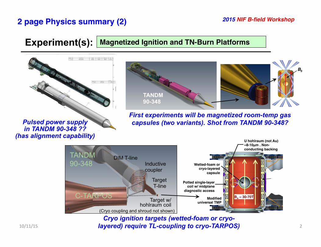
Pulsed power supply in TANDM 90-348 ??
(has alignment capability)
First experiments will be magnetized room-temp gas capsules (two variants). Shot from TANDM 90-348?
TANDM 90-348
C-TARPOS Target w/
hohlraum coil
Inductive coupler
DIM T-line
Target T-line
(Cryo coupling and shroud not shown)
U hohlraum (not Au) ~8-10µm . Non-conducting backing!
Potted single-layer coil w/ midplane
diagnostic access!
Wetted-foam or cryo-layered
capsule!
The pulsed coil is contained within the universal TMP. An important R&D issue is integration of the power supply on NIF
Modified universal TMP!
Bo ~ 30-70T!
Present NIC DT target: Effect of fusion burn product deposition in 2-D with increasing outer surface low-mode perturbation
Ablator CH (2% Si) 195µm !
DT fuel 68µm !
HI-FOOT!
N140304 Hydro Parms: !442TW, 1.86MJ, 3-shock hi-foot!V =3.7e7cm/s, α =2.42!2D clean fusion yield=5.6MJ!
2D Roughnesses:!lmax=30!-Outer ablator!-Dopant surf 1-4!-Ice/ablator!-Inner ice!
1130µm !Ablator CH (2% Si)
195µm !DT fuel 69µm !
φ(θ ) = φ0[1± a.Cos(P(θ +180 / P)]P = 2, 4, 6...The higher-power foot of the laser pulse increases the
early time drive
6 D. E. Hinkel -- Sherwood 2014
"foot"
Park et al., Phys. Rev. Lett. 112, 005001 (2014) Dittrich et al., Phys. Rev. Lett. 112, 055002 (2014) Hurricane et al., Nature 506, 343-348
Radiation Temperature Drive
Courtesy of Tom Dittrich / Omar Hurricane
High Foot X-Ray Drive (3-shock implosion)
Low Foot X-Ray Drive (4-shock implosion)
PPT!
1108µm !
uses
adj
uste
d ra
diat
ion
driv
e to
m
atch
mea
sure
d sh
ock
timin
g an
d im
plos
ion
traj
ecto
ry
Cap
sule
-onl
y si
mul
atio
n
uses
adj
uste
d la
ser
pow
ers
to m
atch
m
easu
red
shoc
k tim
ing
and
traj
ecto
ry
Inte
grat
ed h
ohlra
um
sim
ulat
ion
Hig
h re
solu
tion
caps
ule-
only
sim
ulat
ions
are
our
mos
t de
taile
d m
odel
of i
mpl
osio
n pe
rfor
man
ce
10/2
9/20
12
3 C
lark
—20
12 A
PS-D
PP
abla
tor
DT
ice
Cur
rent
sim
ulat
ions
can
mat
ch m
any
— t
houg
h no
t all
— o
f the
exp
erim
enta
l obs
erva
bles
• C
apsu
le-o
nly
sim
ulat
ions
can
incl
ude
suffi
cien
t res
olut
ion
to
mod
el th
e gr
owth
of
hydr
o. in
stab
ilitie
s
• Th
ey a
lso
incl
ude
as-
shot
dim
ensi
ons,
su
rfac
e fin
ishe
s, a
nd
low
-mod
e dr
ive
asym
met
ries
• O
ur o
bjec
tive
is to
in
clud
e al
l kno
wn
effe
cts
to p
rovi
de a
ba
selin
e fo
r com
paris
on
with
the
data
r! z! B0!
9430µm !
! !57
50!
µm !
uses adjusted radiation drive to match measured shock timing and implosion trajectory
Capsule-only simulation
uses adjusted laser powers to match measured shock timing and trajectory
Integrated hohlraum simulation
High resolution capsule-only simulations are our most detailed model of implosion performance
10/29/2012 3 Clark—2012 APS-DPP
ablator
DT ice
Current simulations can match many — though not all — of the experimental observables
• Capsule-only simulations can include sufficient resolution to model the growth of hydro. instabilities
• They also include as-shot dimensions, surface finishes, and low-mode drive asymmetries
• Our objective is to include all known effects to provide a baseline for comparison with the data
B0!
Cryo ignition targets (wetted-foam or cryo-layered) require TL-coupling to cryo-TARPOS)
TANDM 90-348

Three classes of NIF magnetized ignition/burn platforms are under study in indirect drive
Follow-on !cryo-capsules!
Magnetized room-temp. gas capsules for first experiments!
Room-Temp Gas Metal-Gas Cryo Ignition Rationale B-dep. α heating feedback on
yield (room-temp analog of cryo) Volumetric ign/burn at Tign~6keV with low velocity; other apps
Ignition and propagating burn at reduced hotspot conditions
Max yields (MJ) ~0.1 1 ~1-20
Initial temperature
300K 300K Cryo-layered ~19K Wetted foam: ~19-30K
DT Fuel Gas (~10-15Atm, ~2-3mg/cc) Gas (~29Atm, ~6mg/cc) Solid-DT or wetted foam
Ignition type Volumetric heating Volumetric ignition Hotspot ignition + prop burn
Ti_ign / Ti_max(keV) Likely only α heat. to <10keV ~6 / 20 (Rad. trapped) ~12 / 100
P2-shim capsule option (sausage)!
PPT and PDF Graded lo-Z to hi-Z
pusher/ablator!
Medium pressure!DT gas (~ 6mg/cc)!
0.5µm anti-mix / !anti-hydriding layer!
HDC, B4C (not Be)!Ta, W, Pt,…!
Ablator: CH, HDC, B4C (not Be) !!Cryo-layered DT !or DT wetted foam !
DT gas! (0.3 - 14mg/cc)!
CH, HDC, B4C (not Be) !ablator/pusher!
Medium pressure!DT gas (~2-3mg/cc)!
Al perm. barrier!
Equiv payload to cryo DT!
Magnetized Ignition and TN-Burn Platforms!
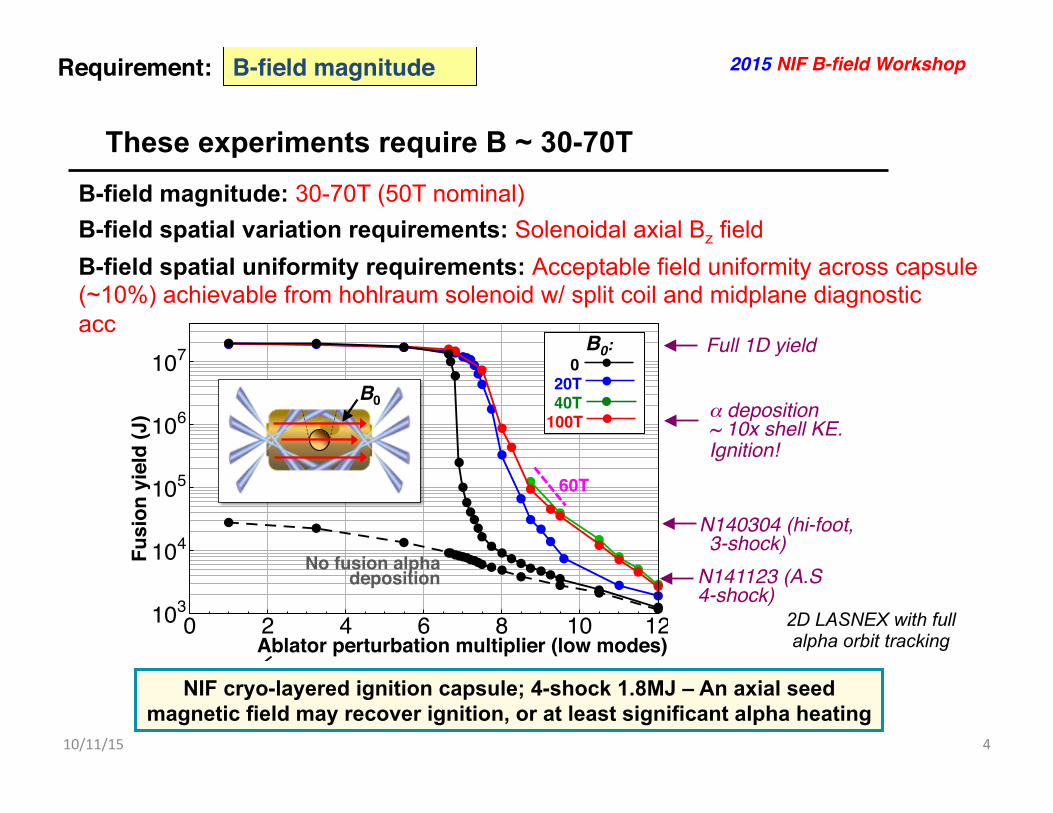
These experiments require B ~ 30-70T
10/11/15% 4%
B-field magnitude!Requirement:!
B-field magnitude: 30-70T (50T nominal) B-field spatial variation requirements: Solenoidal axial Bz field B-field spatial uniformity requirements: Acceptable field uniformity across capsule (~10%) achievable from hohlraum solenoid w/ split coil and midplane diagnostic access
2015 NIF B-field Workshop!
0 2 4 6 8 10 12103
104
105
106
107
An axial seed magnetic field may recover ignition, or at least significant alpha heating
Burn product deposition - On!
Burn product deposition - Escape!
Fusi
on y
ield
(J)!
2D LASNEX simulations with full orbit following of fusion alpha particles
Present NIC DT target: Effect of fusion burn product deposition in 2-D with increasing outer surface low-mode perturbation
1108µm "Ablator CH (2% Si)
195µm "DT fuel 68µm "
Pulse shape: standard 4-shock,
2ns rise, coast"
2D Roughnesses:"-Outer ablator"-Dopant surf 1-4"-Ice/ablator"-Inner ice"
0 2 4 6 8 10 12103
104
105
106
107
Ablator outer perturbation multiplier!
Fusi
on y
ield
(J)!
No fusion alpha deposition!
B0:! 0! 20T! 40T!100T!
uses
adj
uste
d ra
diat
ion
driv
e to
m
atch
mea
sure
d sh
ock
timin
g an
d im
plos
ion
traj
ecto
ry
Cap
sule
-onl
y si
mul
atio
n
uses
adj
uste
d la
ser
pow
ers
to m
atch
m
easu
red
shoc
k tim
ing
and
traj
ecto
ry
Inte
grat
ed h
ohlra
um
sim
ulat
ion
Hig
h re
solu
tion
caps
ule-
only
sim
ulat
ions
are
our
mos
t de
taile
d m
odel
of i
mpl
osio
n pe
rfor
man
ce
10/2
9/20
12
3 C
lark
—20
12 A
PS-D
PP
abla
tor
DT
ice
Cur
rent
sim
ulat
ions
can
mat
ch m
any
— t
houg
h no
t all
— o
f the
exp
erim
enta
l obs
erva
bles
• C
apsu
le-o
nly
sim
ulat
ions
can
incl
ude
suffi
cien
t res
olut
ion
to
mod
el th
e gr
owth
of
hydr
o. in
stab
ilitie
s
• Th
ey a
lso
incl
ude
as-
shot
dim
ensi
ons,
su
rfac
e fin
ishe
s, a
nd
low
-mod
e dr
ive
asym
met
ries
• O
ur o
bjec
tive
is to
in
clud
e al
l kno
wn
effe
cts
to p
rovi
de a
ba
selin
e fo
r com
paris
on
with
the
data
B0!
PPT! PDF! uses
adj
uste
d ra
diat
ion
driv
e to
m
atch
mea
sure
d sh
ock
timin
g an
d im
plos
ion
traj
ecto
ry
Cap
sule
-onl
y si
mul
atio
n
uses
adj
uste
d la
ser
pow
ers
to m
atch
m
easu
red
shoc
k tim
ing
and
traj
ecto
ry
Inte
grat
ed h
ohlra
um
sim
ulat
ion
Hig
h re
solu
tion
caps
ule-
only
sim
ulat
ions
are
our
mos
t de
taile
d m
odel
of i
mpl
osio
n pe
rfor
man
ce
10/2
9/20
12
3 C
lark
—20
12 A
PS-D
PP
abla
tor
DT
ice
Cur
rent
sim
ulat
ions
can
mat
ch m
any
— t
houg
h no
t all
— o
f the
exp
erim
enta
l obs
erva
bles
• C
apsu
le-o
nly
sim
ulat
ions
can
incl
ude
suffi
cien
t res
olut
ion
to
mod
el th
e gr
owth
of
hydr
o. in
stab
ilitie
s
• Th
ey a
lso
incl
ude
as-
shot
dim
ensi
ons,
su
rfac
e fin
ishe
s, a
nd
low
-mod
e dr
ive
asym
met
ries
• O
ur o
bjec
tive
is to
in
clud
e al
l kno
wn
effe
cts
to p
rovi
de a
ba
selin
e fo
r com
paris
on
with
the
data
B0!
PPT! PDF!
PPT and PDF
α deposition ~ 10x shell KE. Ignition!!
N140304 (hi-foot, 3-shock)!
Full 1D yield!
Ablator perturbation multiplier (low modes)!
N141123 (A.S 4-shock)!
Standard NIC CH-abl. 2%Si(X1) 68µm fuel, low foot 4-shock!
60T!
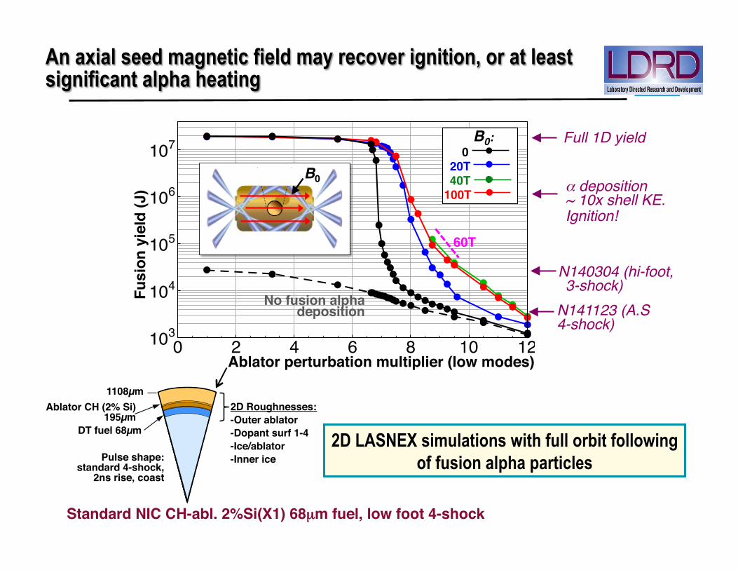
NIF cryo-layered ignition capsule; 4-shock 1.8MJ – An axial seed magnetic field may recover ignition, or at least significant alpha heating
2D LASNEX with full alpha orbit tracking

U hohlraum (not Au) ~8-10µm . Non-conducting backing!
Potted single-layer coil w/ midplane
diagnostic access!
Wetted-foam or cryo-layered
capsule!
The pulsed coil is contained within the universal TMP. An important R&D issue is integration of the power supply on NIF
Modified universal TMP!
Bo ~ 30-70T!
Experiments require an axial hohlraum field with regular hohlraum diagnostic access
10/11/15% 5%
B-field spatial extent + diagnostic access!Requirement:! 2015 NIF B-field Workshop!
Present NIC DT target: Effect of fusion burn product deposition in 2-D with increasing outer surface low-mode perturbation
Ablator CH (2% Si) 195µm !
DT fuel 68µm !
HI-FOOT!
N140304 Hydro Parms: !442TW, 1.86MJ, 3-shock hi-foot!V =3.7e7cm/s, α =2.42!2D clean fusion yield=5.6MJ!
2D Roughnesses:!lmax=30!-Outer ablator!-Dopant surf 1-4!-Ice/ablator!-Inner ice!
1130µm !Ablator CH (2% Si)
195µm !DT fuel 69µm !
φ(θ ) = φ0[1± a.Cos(P(θ +180 / P)]P = 2, 4, 6...The higher-power foot of the laser pulse increases the
early time drive
6 D. E. Hinkel -- Sherwood 2014
"foot"
Park et al., Phys. Rev. Lett. 112, 005001 (2014) Dittrich et al., Phys. Rev. Lett. 112, 055002 (2014) Hurricane et al., Nature 506, 343-348
Radiation Temperature Drive
Courtesy of Tom Dittrich / Omar Hurricane
High Foot X-Ray Drive (3-shock implosion)
Low Foot X-Ray Drive (4-shock implosion)
PPT!
1108µm !
uses
adj
uste
d ra
diat
ion
driv
e to
m
atch
mea
sure
d sh
ock
timin
g an
d im
plos
ion
traj
ecto
ry
Cap
sule
-onl
y si
mul
atio
n
uses
adj
uste
d la
ser
pow
ers
to m
atch
m
easu
red
shoc
k tim
ing
and
traj
ecto
ry
Inte
grat
ed h
ohlra
um
sim
ulat
ion
Hig
h re
solu
tion
caps
ule-
only
sim
ulat
ions
are
our
mos
t de
taile
d m
odel
of i
mpl
osio
n pe
rfor
man
ce
10/2
9/20
12
3 C
lark
—20
12 A
PS-D
PP
abla
tor
DT
ice
Cur
rent
sim
ulat
ions
can
mat
ch m
any
— t
houg
h no
t all
— o
f the
exp
erim
enta
l obs
erva
bles
• C
apsu
le-o
nly
sim
ulat
ions
can
incl
ude
suffi
cien
t res
olut
ion
to
mod
el th
e gr
owth
of
hydr
o. in
stab
ilitie
s
• Th
ey a
lso
incl
ude
as-
shot
dim
ensi
ons,
su
rfac
e fin
ishe
s, a
nd
low
-mod
e dr
ive
asym
met
ries
• O
ur o
bjec
tive
is to
in
clud
e al
l kno
wn
effe
cts
to p
rovi
de a
ba
selin
e fo
r com
paris
on
with
the
data
r! z! B0!
9430µm !
! !57
50!
µm !
uses adjusted radiation drive to match measured shock timing and implosion trajectory
Capsule-only simulation
uses adjusted laser powers to match measured shock timing and trajectory
Integrated hohlraum simulation
High resolution capsule-only simulations are our most detailed model of implosion performance
10/29/2012 3 Clark—2012 APS-DPP
ablator
DT ice
Current simulations can match many — though not all — of the experimental observables
• Capsule-only simulations can include sufficient resolution to model the growth of hydro. instabilities
• They also include as-shot dimensions, surface finishes, and low-mode drive asymmetries
• Our objective is to include all known effects to provide a baseline for comparison with the data
B0!
Cryo targets will require a modified TMP (no conductors outside the
hohlram wall) and new cryo-shroud
• Split, center-fed coil. • 2dConA backlighter access 800x800µm. • 1d self-emission access160x970µm • Zylon composite overwrap • No keyhole shots req’d
Hohlraum test coil
Room temperature targets
• 1d self-emission160x970µm • No starburst if wetted foam
DIM Cap
Spark gap Coupler Hohlraum
coil
Pulsed power supply: ICAR has supplied us five spark-gap-switched capacitors ~4µF$@40kV$(3.2kJ),$60kA

We are performing power supply and hohlraum coil tests in our B490 lab. Coils are wound and potted in B321
Main tank!
SE
CTIO
N A
-AS
CA
LE 5
SE
CTIO
N C
-CS
CA
LE 5
AA
CC
11
22
33
66
77
88
AA
BB
CC
DD
54
54
LAW
RE
NC
E LIV
ER
MO
RE
NA
TION
AL LA
BO
RA
TOR
YLAW
RENCE LIVERMORE NATIONAL SECURITY-LLC, P.O. BOX 808 LIVERM
ORE CA 94551TITLE
SIZE
CA
GE
CO
DE
14067S
CA
LE
DR
AW
ING
NU
MB
ER
RE
V
SH
EE
TO
FU
SE
D O
NA
PP
LICA
TION
DIV
/GR
OU
P
OR
IGIN
ATO
R
DR
AW
N
CH
EC
KE
D
AP
PR
OV
ED
AP
PR
OV
ALS
DA
TE
CLA
SS
IFIED
BY
CO
NTR
AC
T NO
UN
LES
S O
THE
RW
ISE
SP
EC
IFIED
DIM
EN
SIO
NS
IN IN
CH
ES
TOLE
RA
NC
ES
AR
E:
DE
CIM
ALS
: ± .005 AN
GLE
S: ± 1°
DO
NO
T SC
ALE
FRO
M D
RA
WIN
G
THIS W
OR
K WAS PER
FOR
MED
UN
DER
THE AU
SPICES O
F THE U
.S. DEPAR
TMEN
T OF EN
ERG
Y UN
DER
CO
NTR
ACT D
E-AC52-07N
A27344. NEITH
ER TH
E UN
ITED STATES G
OVER
NM
ENT N
OR
LAWR
ENC
ELIVER
MO
RE N
ATION
AL SECU
RITY, LLC
, NO
R AN
Y OF TH
EIR EM
PLOYEES M
AKES ANY W
ARR
ANTY,
EXPRESSED
OR
IMPLIED
OR
ASSUM
ES ANY LEG
AL LIABILITY OR
RESPO
NSIBILITY FO
R TH
EAC
CU
RAC
Y, CO
MPLETEN
ESS OR
USEFU
LNESS O
F ANY IN
FOR
MATIO
N, APPAR
ATUS, PR
OD
UC
T, OR
PRO
CESS D
ISCLO
SED, O
R R
EPRESEN
TS THAT ITS U
SE WO
ULD
NO
T INFR
ING
E PRIVATELY O
WN
EDR
IGH
TS. REFER
ENC
E HER
EIN TO
ANY SPEC
IFIC C
OM
MER
CIAL PR
OD
UC
T, PRO
CESS, O
R SER
VICE BY
TRAD
E NAM
E, TRAD
EMAR
K, MAN
UFAC
TUR
ER, O
R O
THER
WISE D
OES N
OT N
ECESSAR
ILY CO
NSTITU
TE OR
IMPLY ITS EN
DO
RSEM
ENT, R
ECO
MM
END
ATION
, OR
FAVOR
ING
BY THE U
NITED
STATES GO
VERN
MEN
T OR
LAWR
ENC
E LIVERM
OR
E NATIO
NAL SE C
UR
ITY, LLC.
2.000
THIR
D A
NG
LE P
RO
JEC
TION
COIL POTTING FIXTURE CONFIG.1
LEA
13-5005601
3 A
AD
HA
WK
INS
410/16/2014
RH
OD
ES
410/16/2014
PE
RK
INS
310/16/2014
NIF MAGNETIZED TARGETP
ER
KIN
S3
NS
ED
10/16/2014
A
EXPERIMENTAL WINDINGS
Draw
ing Template Form
at:I2013_DR
AW
ING
_IVT
itle Block V
ersion:011714
PE
RK
INS
3
NE
XT A
SS
Y
WB
S
DRAWING
CLASS
C
Beam
Rese
arch
Pro
gra
m
SHDRAWING NUMBER REVLEA13-500560-AA 1
DRAWING:LEA13-500560.idw MODEL: LEA13-500560.ipt INVENTOR 2013
LEA13-500560-AA
INC
HE
S [M
M]
UN
CLA
SS
IFIED
UN
CLA
SS
IFIEDP
roject -Task Num
ber: 39565-898628.1Fabrication Q
uantity:10D
ue: D
one: S
tatus: -SH
AW
N P
ETE
RS
ON
CH
ECK
PRIN
T
CLA
SS
IFIC
AT
ION
: UN
CLA
SS
IFIE
D-L
IMIT
ED
DIS
TR
IBU
TIO
N
6
AP
PR
OV
ED
DR
AW
ND
ATE
DE
SC
RIP
TION
LTRZO
NE
RE
VIS
ION
S
/A
AINITIAL RELEASE
10/16/2014HAW
KINS4PERKINS3
CH
EC
KE
D
RHODES4
Timestam
p-11/12/2014 08:46:AM
0.023
[0.577 mm
] 18 TU
RN
S#24 A
WG
WITH
PO
LYE
STE
R
INS
ULA
TION
0.757[19.224 m
m]
0.700[17.780 mm]
0.600[15.240 mm]
0.500[12.700 m
m]
EP
OX
Y ZY
LON
WR
AP
PIN
G
0.071[1.793 m
m]
0.500
[12.700 mm
]
0.459[11.654 mm]
0.188
[4.775 mm
]
0.460[11.684 mm]
R0.089
[2.252 mm
]
0.875[22.225 m
m]
0.375[9.525 m
m]
0.500[12.700 m
m]
0.324[8.230 mm]
0.201[5.116 m
m]
0.017[0.423 m
m]
MA
ND
RE
L
Zylon composite spool! Coil winding
and potting!B321 Winding
Facility
Center-fed dual coil!6mm dia hohlraum
dimension!50T/70T!
Capacitor!
Spark gap switches!(dry-N2)!
Coil debris tank!
Hohlraum coil!
B490 Lab.
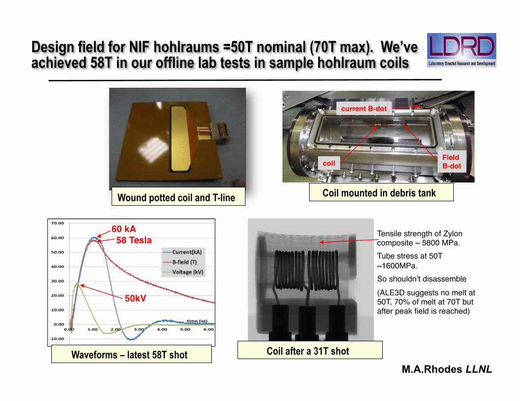
Design field for NIF hohlraums =50T nominal (70T max). We’ve achieved 58T in our offline lab tests in sample hohlraum coils
Wound potted coil and T-line
coil!Field!B-dot!
current B-dot!
58 Tesla!60 kA!
Coil mounted in debris tank
Coil after a 31T shot Waveforms – latest 58T shot
50kV!
Tensile strength of Zylon composite ~ 5800 MPa.!Tube stress at 50T ~1600MPa.!So shouldn’t disassemble!(ALE3D suggests no melt at 50T, 70% of melt at 70T but after peak field is reached)!!
M.A.Rhodes LLNL

A new test tank with NIF-integrable components is under construction for vacuum coil tests this fall in our B490 lab.
We are liaising with NIF to assess 2016-17 integration. The NIF FY16 new experimental capabilities program contains a line item for this
(NNSA MTE 10.3 - NIF Diagnostics, Cryogenics, and Experimental Support)
HV power supply!
Trigger power supply!
Coil test chamber!
“Air” box -!RC318 (C4F8) dielectric fill gas!
Vacuum, diagnostic and
view ports!
Vacuum, feedthrough!
ICA 4µf 40kV capacitor!
Series resistors!
Sparkgap switch (Ar /SF6)!
M.A.Rhodes LLNL
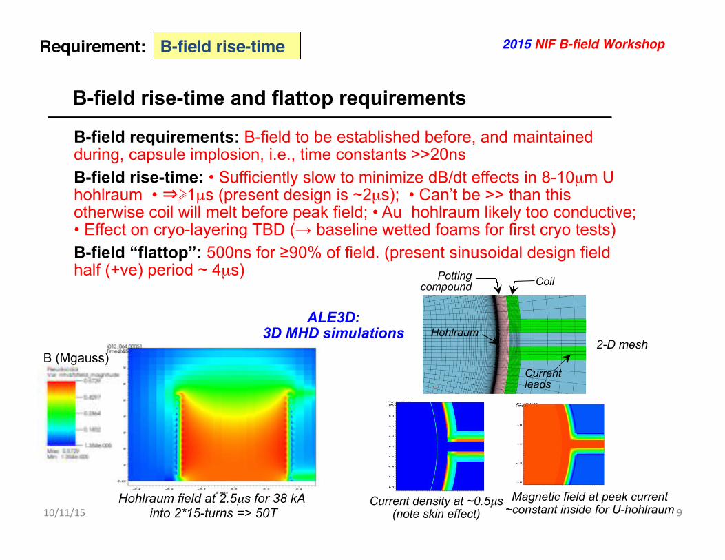
B-field rise-time and flattop requirements
10/11/15% 9%
B-field rise-time!Requirement:! 2015 NIF B-field Workshop!
B-field requirements: B-field to be established before, and maintained during, capsule implosion, i.e., time constants >>20ns B-field rise-time: • Sufficiently slow to minimize dB/dt effects in 8-10µm U hohlraum • 1µs (present design is ~2µs); • Can’t be >> than this otherwise coil will melt before peak field; • Au hohlraum likely too conductive; • Effect on cryo-layering TBD (→ baseline wetted foams for first cryo tests) B-field “flattop”: 500ns for ≥90% of field. (present sinusoidal design field half (+ve) period ~ 4µs)
B (Mgauss)
Hohlraum field at 2.5µs for 38 kA into 2*15-turns => 50T
2-D mesh Hohlraum
Potting compound Coil
Current leads
Current density at ~0.5µs (note skin effect)
Magnetic field at peak current ~constant inside for U-hohlraum
ALE3D: 3D MHD simulations

Other issues:
10/11/15% 2015%NIF%B*field%Workshop%% 10%
Other issues!Requirement:! 2015 NIF B-field Workshop!
Capacitor stored energy in TANDM: 3.2kJ at full charge. Shrapnel case and debris containment? Can it survive gas box depressurization? (Alternative external cable current-supply system?? – we scoped this and discarded in favor of the present in-situ design) Laser pulse shape and protection: All magnetized ignition target designs thus far have conventional 2-4-shock adiabat-shaped pulse shapes so laser considerations are ~same as for regular targets (However, stay tuned for a left-field concept….! ) EMP: Lots of gammas (→Compton electrons) in a compressed magnetic field – especially for the metal-gas targets; Diagnostics protection? dB/dt: Effect of dB/dt on cryo-layering TBD ( baseline wetted foams for first cryo tests). Effects on U hohlraum modeled as ~OK but will be verified in lab tests in the near future Vibrations: Effect of spark gap, cap and coil JXB pulses on alignment? Coupling to cryo targets: We are assessing an inductive coupling concept from room-temperature TANDM T-line to cryo hohlraum+coil (other ideas ?)

10/11/15% 2015%NIF%B*field%Workshop%% 11%
Summary!
B-field magnitude! 30-70 T!
B-field spatial shape / extent!
Axial solenoidal field within a NIF hohlraum volume!
B-field uniformity! ~10% over capsule volume!
B-field rise time! ≥1 µs!
Diagnostic access! Regular NIF requirements for 2dConA, Symcaps and cryo (no keyhole req’d)!
Other! Future coupling to cryo capsules!
Summary%requirements%
2015 NIF B-field Workshop!
Experiment(s): Magnetized Ignition and TN-Burn Platforms!
Room temperature magnetized gas target
TANDM 90-348
PPT and PDF Graded lo-Z to hi-Z
pusher/ablator!
Medium pressure!DT gas (~ 6mg/cc)!
0.5µm anti-mix / !anti-hydriding layer!
HDC, B4C (not Be)!Ta, W, Pt,…!
Ablator: CH, HDC, B4C (not Be) !!Cryo-layered DT !or DT wetted foam !
DT gas! (0.3 - 14mg/cc)!
CH, HDC, B4C (not Be) !ablator/pusher!
Medium pressure!DT gas (~2-3mg/cc)!
Al perm. barrier!
Equiv payload to cryo DT!
TANDM 90-348
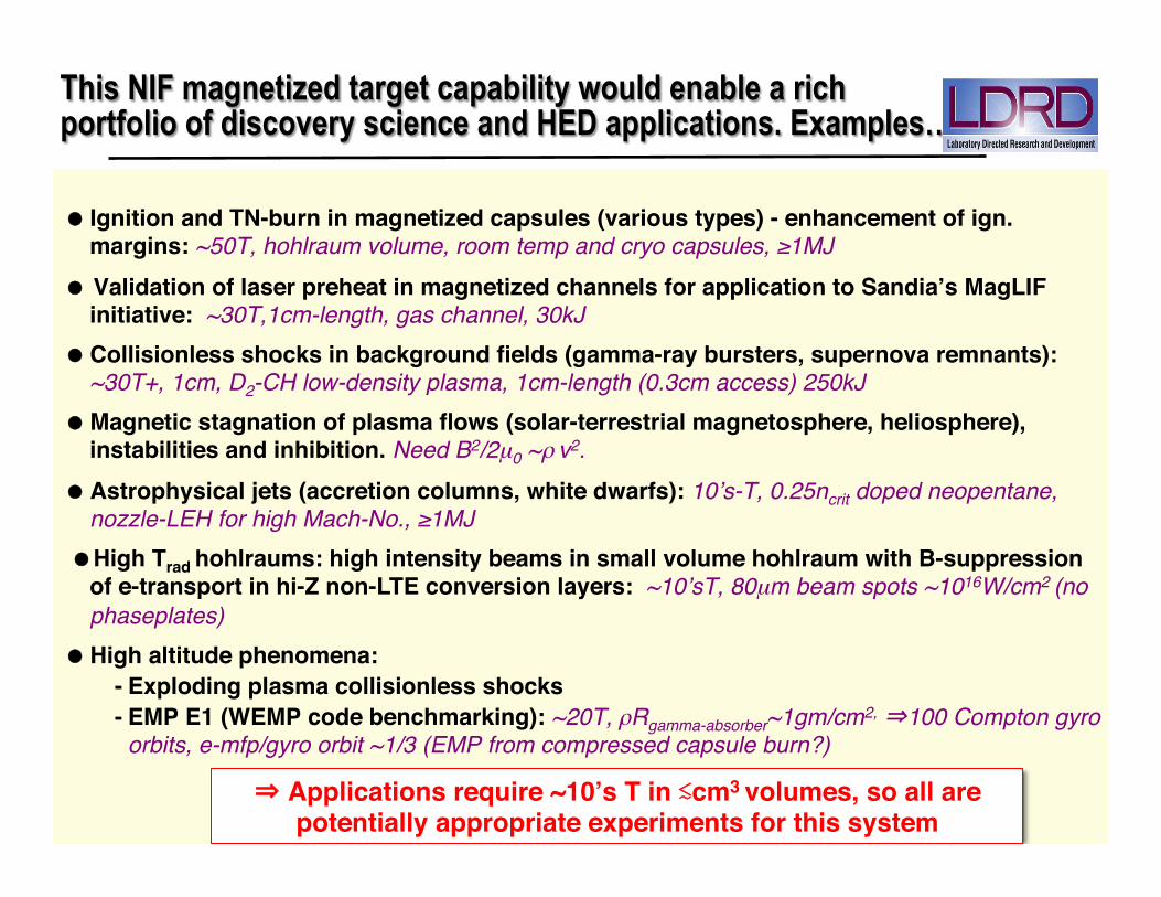
This NIF magnetized target capability would enable a rich portfolio of discovery science and HED applications. Examples… !
!Ignition and TN-burn in magnetized capsules (various types) - enhancement of ign. margins: ~50T, hohlraum volume, room temp and cryo capsules, ≥1MJ !
Validation of laser preheat in magnetized channels for application to Sandia’s MagLIF initiative: ~30T,1cm-length, gas channel, 30kJ !
!Collisionless shocks in background fields (gamma-ray bursters, supernova remnants): ~30T+, 1cm, D2-CH low-density plasma, 1cm-length (0.3cm access) 250kJ!
!Magnetic stagnation of plasma flows (solar-terrestrial magnetosphere, heliosphere), instabilities and inhibition. Need B2/2µ0 ~ρ v2.!
!Astrophysical jets (accretion columns, white dwarfs): 10’s-T, 0.25ncrit doped neopentane, nozzle-LEH for high Mach-No., ≥1MJ !
High Trad hohlraums: high intensity beams in small volume hohlraum with B-suppression
of e-transport in hi-Z non-LTE conversion layers: ~10’sT, 80µm beam spots ~1016W/cm2 (no phaseplates) !
!High altitude phenomena:!-!Exploding plasma collisionless shocks!-!EMP E1 (WEMP code benchmarking): ~20T, ρRgamma-absorber~1gm/cm2, 100 Compton gyro
orbits, e-mfp/gyro orbit ~1/3 (EMP from compressed capsule burn?)!!!!
Applications require ~10’s T in cm3 volumes, so all are potentially appropriate experiments for this system!
Backup Slides
10/11/15% 2015%NIF%B9field%Workshop%% 13%
0 2 4 6 8 10 12103
104
105
106
107
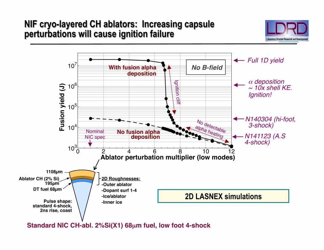
NIF cryo-layered CH ablators: Increasing capsule perturbations will cause ignition failure
Ablator perturbation multiplier (low modes)!
Fusi
on y
ield
(J)! α deposition
~ 10x shell KE. Ignition!!
No fusion alpha deposition!
No B-field!
2D LASNEX simulations
Present NIC DT target: Effect of fusion burn product deposition in 2-D with increasing outer surface low-mode perturbation
1108µm "Ablator CH (2% Si)
195µm "DT fuel 68µm "
Pulse shape: standard 4-shock,
2ns rise, coast"
2D Roughnesses:"-Outer ablator"-Dopant surf 1-4"-Ice/ablator"-Inner ice"
Standard NIC CH-abl. 2%Si(X1) 68µm fuel, low foot 4-shock!
N141123 (A.S 4-shock)!
N140304 (hi-foot, 3-shock)!
Nominal !NIC spec!
Full 1D yield!With fusion alpha
deposition!
Ignition cliff!
0 2 4 6 8 10 12103
104
105
106
107
An axial seed magnetic field may recover ignition, or at least significant alpha heating
Burn product deposition - On!
Burn product deposition - Escape!
Fusi
on y
ield
(J)!
2D LASNEX simulations with full orbit following of fusion alpha particles
Present NIC DT target: Effect of fusion burn product deposition in 2-D with increasing outer surface low-mode perturbation
1108µm "Ablator CH (2% Si)
195µm "DT fuel 68µm "
Pulse shape: standard 4-shock,
2ns rise, coast"
2D Roughnesses:"-Outer ablator"-Dopant surf 1-4"-Ice/ablator"-Inner ice"
0 2 4 6 8 10 12103
104
105
106
107
Ablator outer perturbation multiplier!
Fusi
on y
ield
(J)!
No fusion alpha deposition!
B0:! 0! 20T! 40T!100T!
uses
adj
uste
d ra
diat
ion
driv
e to
m
atch
mea
sure
d sh
ock
timin
g an
d im
plos
ion
traj
ecto
ry
Cap
sule
-onl
y si
mul
atio
n
uses
adj
uste
d la
ser
pow
ers
to m
atch
m
easu
red
shoc
k tim
ing
and
traj
ecto
ry
Inte
grat
ed h
ohlra
um
sim
ulat
ion
Hig
h re
solu
tion
caps
ule-
only
sim
ulat
ions
are
our
mos
t de
taile
d m
odel
of i
mpl
osio
n pe
rfor
man
ce
10/2
9/20
12
3 C
lark
—20
12 A
PS-D
PP
abla
tor
DT
ice
Cur
rent
sim
ulat
ions
can
mat
ch m
any
— t
houg
h no
t all
— o
f the
exp
erim
enta
l obs
erva
bles
• C
apsu
le-o
nly
sim
ulat
ions
can
incl
ude
suffi
cien
t res
olut
ion
to
mod
el th
e gr
owth
of
hydr
o. in
stab
ilitie
s
• Th
ey a
lso
incl
ude
as-
shot
dim
ensi
ons,
su
rfac
e fin
ishe
s, a
nd
low
-mod
e dr
ive
asym
met
ries
• O
ur o
bjec
tive
is to
in
clud
e al
l kno
wn
effe
cts
to p
rovi
de a
ba
selin
e fo
r com
paris
on
with
the
data
B0!
PPT! PDF! uses
adj
uste
d ra
diat
ion
driv
e to
m
atch
mea
sure
d sh
ock
timin
g an
d im
plos
ion
traj
ecto
ry
Cap
sule
-onl
y si
mul
atio
n
uses
adj
uste
d la
ser
pow
ers
to m
atch
m
easu
red
shoc
k tim
ing
and
traj
ecto
ry
Inte
grat
ed h
ohlra
um
sim
ulat
ion
Hig
h re
solu
tion
caps
ule-
only
sim
ulat
ions
are
our
mos
t de
taile
d m
odel
of i
mpl
osio
n pe
rfor
man
ce
10/2
9/20
12
3 C
lark
—20
12 A
PS-D
PP
abla
tor
DT
ice
Cur
rent
sim
ulat
ions
can
mat
ch m
any
— t
houg
h no
t all
— o
f the
exp
erim
enta
l obs
erva
bles
• C
apsu
le-o
nly
sim
ulat
ions
can
incl
ude
suffi
cien
t res
olut
ion
to
mod
el th
e gr
owth
of
hydr
o. in
stab
ilitie
s
• Th
ey a
lso
incl
ude
as-
shot
dim
ensi
ons,
su
rfac
e fin
ishe
s, a
nd
low
-mod
e dr
ive
asym
met
ries
• O
ur o
bjec
tive
is to
in
clud
e al
l kno
wn
effe
cts
to p
rovi
de a
ba
selin
e fo
r com
paris
on
with
the
data
B0!
PPT! PDF!
PPT and PDF
α deposition ~ 10x shell KE. Ignition!!
N140304 (hi-foot, 3-shock)!
Full 1D yield!
Ablator perturbation multiplier (low modes)!
N141123 (A.S 4-shock)!
Standard NIC CH-abl. 2%Si(X1) 68µm fuel, low foot 4-shock!
60T!
0 2 4 6 8 10 12103
104
105
106
107
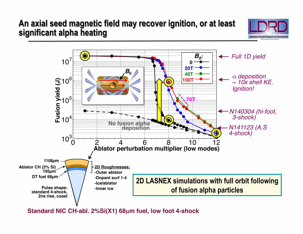
An axial seed magnetic field may recover ignition, or at least significant alpha heating
Burn product deposition - On!
Burn product deposition - Escape!
Fusi
on y
ield
(J)!
2D LASNEX simulations with full orbit following of fusion alpha particles
Present NIC DT target: Effect of fusion burn product deposition in 2-D with increasing outer surface low-mode perturbation
1108µm "Ablator CH (2% Si)
195µm "DT fuel 68µm "
Pulse shape: standard 4-shock,
2ns rise, coast"
2D Roughnesses:"-Outer ablator"-Dopant surf 1-4"-Ice/ablator"-Inner ice"
0 2 4 6 8 10 12103
104
105
106
107
Ablator outer perturbation multiplier!
Fusi
on y
ield
(J)!
No fusion alpha deposition!
B0:! 0! 20T! 40T!100T!
uses
adj
uste
d ra
diat
ion
driv
e to
m
atch
mea
sure
d sh
ock
timin
g an
d im
plos
ion
traj
ecto
ry
Cap
sule
-onl
y si
mul
atio
n
uses
adj
uste
d la
ser
pow
ers
to m
atch
m
easu
red
shoc
k tim
ing
and
traj
ecto
ry
Inte
grat
ed h
ohlra
um
sim
ulat
ion
Hig
h re
solu
tion
caps
ule-
only
sim
ulat
ions
are
our
mos
t de
taile
d m
odel
of i
mpl
osio
n pe
rfor
man
ce
10/2
9/20
12
3 C
lark
—20
12 A
PS-D
PP
abla
tor
DT
ice
Cur
rent
sim
ulat
ions
can
mat
ch m
any
— t
houg
h no
t all
— o
f the
exp
erim
enta
l obs
erva
bles
• C
apsu
le-o
nly
sim
ulat
ions
can
incl
ude
suffi
cien
t res
olut
ion
to
mod
el th
e gr
owth
of
hydr
o. in
stab
ilitie
s
• Th
ey a
lso
incl
ude
as-
shot
dim
ensi
ons,
su
rfac
e fin
ishe
s, a
nd
low
-mod
e dr
ive
asym
met
ries
• O
ur o
bjec
tive
is to
in
clud
e al
l kno
wn
effe
cts
to p
rovi
de a
ba
selin
e fo
r com
paris
on
with
the
data
B0!
PPT! PDF! uses
adj
uste
d ra
diat
ion
driv
e to
m
atch
mea
sure
d sh
ock
timin
g an
d im
plos
ion
traj
ecto
ry
Cap
sule
-onl
y si
mul
atio
n
uses
adj
uste
d la
ser
pow
ers
to m
atch
m
easu
red
shoc
k tim
ing
and
traj
ecto
ry
Inte
grat
ed h
ohlra
um
sim
ulat
ion
Hig
h re
solu
tion
caps
ule-
only
sim
ulat
ions
are
our
mos
t de
taile
d m
odel
of i
mpl
osio
n pe
rfor
man
ce
10/2
9/20
12
3 C
lark
—20
12 A
PS-D
PP
abla
tor
DT
ice
Cur
rent
sim
ulat
ions
can
mat
ch m
any
— t
houg
h no
t all
— o
f the
exp
erim
enta
l obs
erva
bles
• C
apsu
le-o
nly
sim
ulat
ions
can
incl
ude
suffi
cien
t res
olut
ion
to
mod
el th
e gr
owth
of
hydr
o. in
stab
ilitie
s
• Th
ey a
lso
incl
ude
as-
shot
dim
ensi
ons,
su
rfac
e fin
ishe
s, a
nd
low
-mod
e dr
ive
asym
met
ries
• O
ur o
bjec
tive
is to
in
clud
e al
l kno
wn
effe
cts
to p
rovi
de a
ba
selin
e fo
r com
paris
on
with
the
data
B0!
PPT! PDF!
PPT and PDF
α deposition ~ 10x shell KE. Ignition!!
N140304 (hi-foot, 3-shock)!
Full 1D yield!
Ablator perturbation multiplier (low modes)!
N141123 (A.S 4-shock)!
Standard NIC CH-abl. 2%Si(X1) 68µm fuel, low foot 4-shock!
70T!
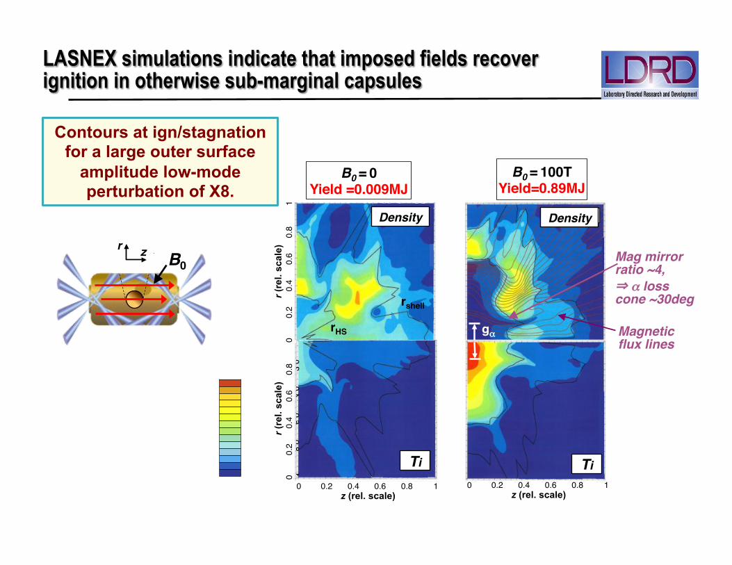
LASNEX simulations indicate that imposed fields recover ignition in otherwise sub-marginal capsules
0 !0.2 !0.4 !0.6 !0.8 !1!z (rel. scale)
0 !0.2 !0.4 !0.6 !0.8 !1!z (rel. scale)
r (re
l. sc
ale)
0
!0.2
!0.4
!0.6
!0.8
!1!
r (re
l. sc
ale)
0
!0.2
!0.4
!0.6
!0.8
!1!
B0 = 0!Yield =0.009MJ!
B0 = 100T!Yield=0.89MJ!
CH cryo capsule, 4-shock. Contours at stagnation for a large outer surface amplitude perturbation of X8.
Flux lines!0 !0.2 !0.4 !0.6 !0.8 !1!z (rel. scale)
0 !0.2 !0.4 !0.6 !0.8 !1!z (rel. scale)
r (rel. scale)
0
!0.2
!0.4
!0.6
!0.8
!1!
r (rel. scale)
0
!0.2
!0.4
!0.6
!0.8
!1!
0 !0.2 !0.4 !0.6 !0.8 !1!z (rel. scale)
0 !0.2 !0.4 !0.6 !0.8 !1!z (rel. scale)
r (rel. scale)
0
!0.2
!0.4
!0.6
!0.8
!1!
r (rel. scale)
0
!0.2
!0.4
!0.6
!0.8
!1!
Density! Density!
Ti! Ti!
0 !0.2 !0.4 !0.6 !0.8 !1!z (rel. scale)
0 !0.2 !0.4 !0.6 !0.8 !1!z (rel. scale)
r (re
l. sc
ale)
0
!0.2
!0.4
!0.6
!0.8
!1!
r (re
l. sc
ale)
0
!0.2
!0.4
!0.6
!0.8
!1!
0 !0.2 !0.4 !0.6 !0.8 !1!z (rel. scale)
0 !0.2 !0.4 !0.6 !0.8 !1!z (rel. scale)
r (re
l. sc
ale)
0
!0.2
!0.4
!0.6
!0.8
!1!
r (re
l. sc
ale)
0
!0.2
!0.4
!0.6
!0.8
!1! gα"rHS"
rshell"
0 !0.2 !0.4 !0.6 !0.8 !1!z (rel. scale)
0 !0.2 !0.4 !0.6 !0.8 !1!z (rel. scale)
r (re
l. sc
ale)
0
!0.2
!0.4
!0.6
!0.8
!1!
r (re
l. sc
ale)
0
!0.2
!0.4
!0.6
!0.8
!1!
B0 = 0!Yield =0.009MJ!
B0 = 100T!Yield=0.89MJ!
CH cryo capsule, 4-shock. Contours at stagnation for a large outer surface amplitude perturbation of X8.
Flux lines!0 !0.2 !0.4 !0.6 !0.8 !1!z (rel. scale)
0 !0.2 !0.4 !0.6 !0.8 !1!z (rel. scale)
r (rel. scale)
0
!0.2
!0.4
!0.6
!0.8
!1!
r (rel. scale)
0
!0.2
!0.4
!0.6
!0.8
!1!
0 !0.2 !0.4 !0.6 !0.8 !1!z (rel. scale)
0 !0.2 !0.4 !0.6 !0.8 !1!z (rel. scale)
r (rel. scale)
0
!0.2
!0.4
!0.6
!0.8
!1!
r (rel. scale)
0
!0.2
!0.4
!0.6
!0.8
!1!
Density! Density!
Ti! Ti!
0 !0.2 !0.4 !0.6 !0.8 !1!z (rel. scale)
0 !0.2 !0.4 !0.6 !0.8 !1!z (rel. scale)
r (re
l. sc
ale)
0
!0.2
!0.4
!0.6
!0.8
!1!
r (re
l. sc
ale)
0
!0.2
!0.4
!0.6
!0.8
!1!
0 !0.2 !0.4 !0.6 !0.8 !1!z (rel. scale)
0 !0.2 !0.4 !0.6 !0.8 !1!z (rel. scale)
r (re
l. sc
ale)
0
!0.2
!0.4
!0.6
!0.8
!1!
r (re
l. sc
ale)
0
!0.2
!0.4
!0.6
!0.8
!1! gα"rHS"
rshell"
Contours at ign/stagnation for a large outer surface
amplitude low-mode perturbation of X8.
Magnetic flux lines!
uses
adj
uste
d ra
diat
ion
driv
e to
m
atch
mea
sure
d sh
ock
timin
g an
d im
plos
ion
traj
ecto
ry
Cap
sule
-onl
y si
mul
atio
n
uses
adj
uste
d la
ser
pow
ers
to m
atch
m
easu
red
shoc
k tim
ing
and
traj
ecto
ry
Inte
grat
ed h
ohlra
um
sim
ulat
ion
Hig
h re
solu
tion
caps
ule-
only
sim
ulat
ions
are
our
mos
t de
taile
d m
odel
of i
mpl
osio
n pe
rfor
man
ce
10/2
9/20
12
3 C
lark
—20
12 A
PS-D
PP
abla
tor
DT
ice
Cur
rent
sim
ulat
ions
can
mat
ch m
any
— t
houg
h no
t all
— o
f the
exp
erim
enta
l obs
erva
bles
• C
apsu
le-o
nly
sim
ulat
ions
can
incl
ude
suffi
cien
t res
olut
ion
to
mod
el th
e gr
owth
of
hydr
o. in
stab
ilitie
s
• Th
ey a
lso
incl
ude
as-
shot
dim
ensi
ons,
su
rfac
e fin
ishe
s, a
nd
low
-mod
e dr
ive
asym
met
ries
• O
ur o
bjec
tive
is to
in
clud
e al
l kno
wn
effe
cts
to p
rovi
de a
ba
selin
e fo
r com
paris
on
with
the
data
B0!
PPT!
PDF! uses
adj
uste
d ra
diat
ion
driv
e to
m
atch
mea
sure
d sh
ock
timin
g an
d im
plos
ion
traj
ecto
ry
Cap
sule
-onl
y si
mul
atio
n
uses
adj
uste
d la
ser
pow
ers
to m
atch
m
easu
red
shoc
k tim
ing
and
traj
ecto
ry
Inte
grat
ed h
ohlra
um
sim
ulat
ion
Hig
h re
solu
tion
caps
ule-
only
sim
ulat
ions
are
our
mos
t de
taile
d m
odel
of i
mpl
osio
n pe
rfor
man
ce
10/2
9/20
12
3 C
lark
—20
12 A
PS-D
PP
abla
tor
DT
ice
Cur
rent
sim
ulat
ions
can
mat
ch m
any
— t
houg
h no
t all
— o
f the
exp
erim
enta
l obs
erva
bles
• C
apsu
le-o
nly
sim
ulat
ions
can
incl
ude
suffi
cien
t res
olut
ion
to
mod
el th
e gr
owth
of
hydr
o. in
stab
ilitie
s
• Th
ey a
lso
incl
ude
as-
shot
dim
ensi
ons,
su
rfac
e fin
ishe
s, a
nd
low
-mod
e dr
ive
asym
met
ries
• O
ur o
bjec
tive
is to
in
clud
e al
l kno
wn
effe
cts
to p
rovi
de a
ba
selin
e fo
r com
paris
on
with
the
data
B0!
PPT! PDF! uses
adj
uste
d ra
diat
ion
driv
e to
m
atch
mea
sure
d sh
ock
timin
g an
d im
plos
ion
traj
ecto
ry
Cap
sule
-onl
y si
mul
atio
n
uses
adj
uste
d la
ser
pow
ers
to m
atch
m
easu
red
shoc
k tim
ing
and
traj
ecto
ry
Inte
grat
ed h
ohlra
um
sim
ulat
ion
Hig
h re
solu
tion
caps
ule-
only
sim
ulat
ions
are
our
mos
t de
taile
d m
odel
of i
mpl
osio
n pe
rfor
man
ce
10/2
9/20
12
3 C
lark
—20
12 A
PS-D
PP
abla
tor
DT
ice
Cur
rent
sim
ulat
ions
can
mat
ch m
any
— t
houg
h no
t all
— o
f the
exp
erim
enta
l obs
erva
bles
• C
apsu
le-o
nly
sim
ulat
ions
can
incl
ude
suffi
cien
t res
olut
ion
to
mod
el th
e gr
owth
of
hydr
o. in
stab
ilitie
s
• Th
ey a
lso
incl
ude
as-
shot
dim
ensi
ons,
su
rfac
e fin
ishe
s, a
nd
low
-mod
e dr
ive
asym
met
ries
• O
ur o
bjec
tive
is to
in
clud
e al
l kno
wn
effe
cts
to p
rovi
de a
ba
selin
e fo
r com
paris
on
with
the
data
B0!
PPT! PDF!
r! z!
Density! Density!
Ti! Ti!
Mag mirror ratio ~4, ! α loss cone ~30deg!

N140304 Data Fusion yield Nn=9.43e15, 26.6kJ Nn=8.88e15, 25.1kJ Nn=8.49e16, 240kJ Ti_Brysk (keV) 5.55 (Incl Doppler?) 3.62 9.50
Ti(0) max (keV) – 6.64 15.0
ρRhs/ρRshell 0.140/0.775 0.338/0.740 0.266/1.13
Phs (Gbar) 173 221 349
Conv. ratio 33.5 33.0 37.1
Yield–no α dep. 12.3kJ 11.6kJ 14.9kJ
Apply angle-dep. P4 rad flux perturbation to approx. match
N140304 3-shock hi-foot inflight + stagnation params!
Present NIC DT target: Effect of fusion burn product deposition in 2-D with increasing outer surface low-mode perturbation
Present NIC DT target: Effect of fusion burn product deposition in 2-D with increasing outer surface low-mode perturbation
2D Perturbed. No B 2D Perturbed. B0=50T
Density!
T i!
Density!
T i!At max Ydot.! At ign.!
Flux lines!
gα#
Run
5976
_0.2
1!
Run
5975
_0.2
1!
Present NIC DT target: Effect of fusion burn product deposition in 2-D with increasing outer surface low-mode perturbation
1108µm !Ablator CH (2% Si)
195µm !
uses
adj
uste
d ra
diat
ion
driv
e to
m
atch
mea
sure
d sh
ock
timin
g an
d im
plos
ion
traj
ecto
ry
Cap
sule
-onl
y si
mul
atio
n
uses
adj
uste
d la
ser
pow
ers
to m
atch
m
easu
red
shoc
k tim
ing
and
traj
ecto
ry
Inte
grat
ed h
ohlra
um
sim
ulat
ion
Hig
h re
solu
tion
caps
ule-
only
sim
ulat
ions
are
our
mos
t de
taile
d m
odel
of i
mpl
osio
n pe
rfor
man
ce
10/2
9/20
12
3 C
lark
—20
12 A
PS-D
PP
abla
tor
DT
ice
Cur
rent
sim
ulat
ions
can
mat
ch m
any
— t
houg
h no
t all
— o
f the
exp
erim
enta
l obs
erva
bles
• C
apsu
le-o
nly
sim
ulat
ions
can
incl
ude
suffi
cien
t res
olut
ion
to
mod
el th
e gr
owth
of
hydr
o. in
stab
ilitie
s
• Th
ey a
lso
incl
ude
as-
shot
dim
ensi
ons,
su
rfac
e fin
ishe
s, a
nd
low
-mod
e dr
ive
asym
met
ries
• O
ur o
bjec
tive
is to
in
clud
e al
l kno
wn
effe
cts
to p
rovi
de a
ba
selin
e fo
r com
paris
on
with
the
data
DT fuel 68µm !
r! z! B0!
9430µm !
! !57
50!
µm !
HI-FOOT!
N140304 Hydro Parms: !442TW, 1.86MJ, 3-shock hi-foot!V =3.7e7cm/s, α =2.42!2D clean fusion yield=9.2MJ!
2D Roughnesses:!lmax=30!-Outer ablator!-Dopant surf 1-4!-Ice/ablator!-Inner ice!
1130µm !Ablator CH (2% Si)
195µm !DT fuel 69µm !
φ(θ ) = φ0[1± a.Cos(P(θ +180 / P)]P = 2, 4, 6...
The higher-power foot of the laser pulse increases the early time drive
6 D. E. Hinkel -- Sherwood 2014
"foot"
Park et al., Phys. Rev. Lett. 112, 005001 (2014) Dittrich et al., Phys. Rev. Lett. 112, 055002 (2014) Hurricane et al., Nature 506, 343-348
Radiation Temperature Drive
Courtesy of Tom Dittrich / Omar Hurricane
High Foot X-Ray Drive (3-shock implosion)
Low Foot X-Ray Drive (4-shock implosion)
PPT!
2D clean fusion yield=5.7MJ!
NIF cryo CH capsules: What does a compressed B-field do for a 3-shock Hi-Foot implosion?
2D x1 rough. fusion yield=5.7MJ!

NIF 3-shock cryo-HDC capsules: Implosion departs further from sphericity as seed field increases beyond ~40 T
-1 0 -1 -1 0 -1 -1 0 -1
-1
0
-
1
HDC 3-shock: Density contours @ignition
z (rel. scale)
r (re
l. sc
ale)
- HDC 3-Shock. Nominal roughness - Optimum seed field for an HDC 3-shock
capsule is around 40T
D.D.Ho LLNL
uses
adj
uste
d ra
diat
ion
driv
e to
m
atch
mea
sure
d sh
ock
timin
g an
d im
plos
ion
traj
ecto
ry
Cap
sule
-onl
y si
mul
atio
n
uses
adj
uste
d la
ser
pow
ers
to m
atch
m
easu
red
shoc
k tim
ing
and
traj
ecto
ry
Inte
grat
ed h
ohlra
um
sim
ulat
ion
Hig
h re
solu
tion
caps
ule-
only
sim
ulat
ions
are
our
mos
t de
taile
d m
odel
of i
mpl
osio
n pe
rfor
man
ce
10/2
9/20
12
3 C
lark
—20
12 A
PS-D
PP
abla
tor
DT
ice
Cur
rent
sim
ulat
ions
can
mat
ch m
any
— t
houg
h no
t all
— o
f the
exp
erim
enta
l obs
erva
bles
• C
apsu
le-o
nly
sim
ulat
ions
can
incl
ude
suffi
cien
t res
olut
ion
to
mod
el th
e gr
owth
of
hydr
o. in
stab
ilitie
s
• Th
ey a
lso
incl
ude
as-
shot
dim
ensi
ons,
su
rfac
e fin
ishe
s, a
nd
low
-mod
e dr
ive
asym
met
ries
• O
ur o
bjec
tive
is to
in
clud
e al
l kno
wn
effe
cts
to p
rovi
de a
ba
selin
e fo
r com
paris
on
with
the
data
B0!
PPT!
PDF! uses
adj
uste
d ra
diat
ion
driv
e to
m
atch
mea
sure
d sh
ock
timin
g an
d im
plos
ion
traj
ecto
ry
Cap
sule
-onl
y si
mul
atio
n
uses
adj
uste
d la
ser
pow
ers
to m
atch
m
easu
red
shoc
k tim
ing
and
traj
ecto
ry
Inte
grat
ed h
ohlra
um
sim
ulat
ion
Hig
h re
solu
tion
caps
ule-
only
sim
ulat
ions
are
our
mos
t de
taile
d m
odel
of i
mpl
osio
n pe
rfor
man
ce
10/2
9/20
12
3 C
lark
—20
12 A
PS-D
PP
abla
tor
DT
ice
Cur
rent
sim
ulat
ions
can
mat
ch m
any
— t
houg
h no
t all
— o
f the
exp
erim
enta
l obs
erva
bles
• C
apsu
le-o
nly
sim
ulat
ions
can
incl
ude
suffi
cien
t res
olut
ion
to
mod
el th
e gr
owth
of
hydr
o. in
stab
ilitie
s
• Th
ey a
lso
incl
ude
as-
shot
dim
ensi
ons,
su
rfac
e fin
ishe
s, a
nd
low
-mod
e dr
ive
asym
met
ries
• O
ur o
bjec
tive
is to
in
clud
e al
l kno
wn
effe
cts
to p
rovi
de a
ba
selin
e fo
r com
paris
on
with
the
data
B0!
PPT! PDF! uses
adj
uste
d ra
diat
ion
driv
e to
m
atch
mea
sure
d sh
ock
timin
g an
d im
plos
ion
traj
ecto
ry
Cap
sule
-onl
y si
mul
atio
n
uses
adj
uste
d la
ser
pow
ers
to m
atch
m
easu
red
shoc
k tim
ing
and
traj
ecto
ry
Inte
grat
ed h
ohlra
um
sim
ulat
ion
Hig
h re
solu
tion
caps
ule-
only
sim
ulat
ions
are
our
mos
t de
taile
d m
odel
of i
mpl
osio
n pe
rfor
man
ce
10/2
9/20
12
3 C
lark
—20
12 A
PS-D
PP
abla
tor
DT
ice
Cur
rent
sim
ulat
ions
can
mat
ch m
any
— t
houg
h no
t all
— o
f the
exp
erim
enta
l obs
erva
bles
• C
apsu
le-o
nly
sim
ulat
ions
can
incl
ude
suffi
cien
t res
olut
ion
to
mod
el th
e gr
owth
of
hydr
o. in
stab
ilitie
s
• Th
ey a
lso
incl
ude
as-
shot
dim
ensi
ons,
su
rfac
e fin
ishe
s, a
nd
low
-mod
e dr
ive
asym
met
ries
• O
ur o
bjec
tive
is to
in
clud
e al
l kno
wn
effe
cts
to p
rovi
de a
ba
selin
e fo
r com
paris
on
with
the
data
B0!
PPT! PDF!
r! z!
40 T seed field 50 T seed field 70 T seed field

Slide 20
NIF Polar Direct Drive with magnetized HDC gas capsules (B. G. Logan)
Shell ρR (g/cm2)
Initial applied magnetic field Bzo (T)
Ignition cliff
Magnetic field pressure competes with hydro pressure
Recommended field for NIF
MPDD experiments
Fusion yield (kJ)
Gas convergence ratio
Ignition cliff
HDC room temperature gas capsule in polar direct drive have the potential for over 1MJ yield with an imposed magnetic field
190km/s, 7.9mg/cc fill
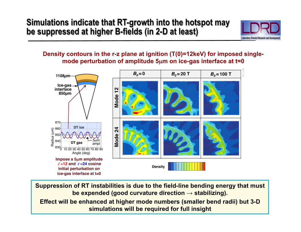
B-field suppression of RT instability at hotspot boundary (in 2-D): Density contours in the r-z plane at ignition (T(0)=12keV) for imposed single-
mode cosine perturbation of amplitude 5µm on ice-gas interface at t=0
1108µm !!!
Ice-gas interface!
850µm !
Impose a 5µm amplitude! l =12 and l =24 cosine initial perturbation on ice-gas interface at t=0!
Angle (deg)!
Rad
ius
(µm
)!
0 10 20 30 40 50 60 70 80 90830
840
850
860
870DT ice!
DT gas!5µm ampl!
B-field suppression of RT instability at hotspot boundary: Density contours in the r-z plane at ignition (T(0)=12keV) for imposed single-
mode cosine perturbation of amplitude 5µm on ice-gas interface at t=0
B0 = 0! B0 = 100 T!B0 = 20 T!
Mod
e 12!
Mod
e 24!
1108µm !!!
Ice-gas interface!
850µm !
5µm amplitude! l =12 and l =24 cosine initial perturbation on ice-gas interface at t=0!
Angle (deg)!
Rad
ius
(µm
)!
0 10 20 30 40 50 60 70 80 90830
840
850
860
870DT ice!
DT gas!
Density!
5µm ampl!
L. J. Perkins, LLNL, June 2013!
Suppression of RT instabilities is due to the field-line bending energy that must be expended (good curvature direction → stabilizing).
Effect will be enhanced at higher mode numbers (smaller bend radii) but 3-D simulations will be required for full insight
Density contours in the r-z plane at ignition (T(0)=12keV) for imposed single-mode perturbation of amplitude 5µm on ice-gas interface at t=0
Simulations indicate that RT-growth into the hotspot may be suppressed at higher B-fields (in 2-D at least)
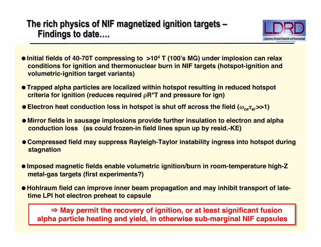
The rich physics of NIF magnetized ignition targets – Findings to date….
May permit the recovery of ignition, or at least significant fusion alpha particle heating and yield, in otherwise sub-marginal NIF capsules
Electron heat conduction loss in hotspot is shut off across the field (ωceτei >>1)!
Mirror fields in sausage implosions provide further insulation to electron and alpha conduction loss (as could frozen-in field lines spun up by resid.-KE)!
Compressed field may suppress Rayleigh-Taylor instability ingress into hotspot during stagnation!
Initial fields of 40-70T compressing to >104 T (100’s MG) under implosion can relax conditions for ignition and thermonuclear burn in NIF targets (hotspot-ignition and volumetric-ignition target variants)!
Trapped alpha particles are localized within hotspot resulting in reduced hotspot criteria for ignition (reduces required ρR*T and pressure for ign)!
!
!
!
!
Imposed magnetic fields enable volumetric ignition/burn in room-temperature high-Z metal-gas targets (first experiments?)!
Hohlraum field can improve inner beam propagation and may inhibit transport of late-time LPI hot electron preheat to capsule!
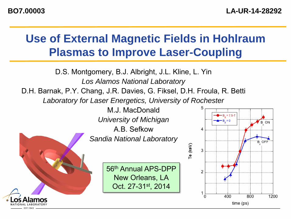
1
Use of External Magnetic Fields in Hohlraum Plasmas to Improve Laser-Coupling
D.S. Montgomery, B.J. Albright, J.L. Kline, L. Yin Los Alamos National Laboratory
D.H. Barnak, P.Y. Chang, J.R. Davies, G. Fiksel, D.H. Froula, R. Betti Laboratory for Laser Energetics, University of Rochester
M.J. MacDonald University of Michigan
A.B. Sefkow Sandia National Laboratory
BO7.00003 LA-UR-14-28292
56th Annual APS-DPP New Orleans, LA Oct. 27-31st, 2014

2
Use of External Magnetic Fields in Hohlraum Plasmas to Improve Laser-Coupling Increased underdense plasma temperatures are desirable for
NIF ignition hohlraums - improve laser propagation through long-scale-length low-Z plasma
(less inverse bremsstrahlung absorption) - possibly mitigate LPI with higher Te (higher kλD, more Landau
damping)
Magnetic insulation can increase the plasma temperature with Bz ≥ 10-T in gas-filled hohlraums
Omega experiments using gas-filled hohlraums demonstrate an increased plasma temperature with Bz = 7.5-T - plasma conditions measured with 4ω Thomson scattering
- 2-D HYDRA simulations are in good agreement with experimental results
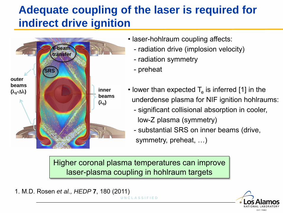
U N C L A S S I F I E D
Adequate coupling of the laser is required for indirect drive ignition
inner beams (λ0)
outer beams (λ0-∆λ)
x-beam transfer
SRS
• laser-hohlraum coupling affects: - radiation drive (implosion velocity) - radiation symmetry - preheat • lower than expected Te is inferred [1] in the underdense plasma for NIF ignition hohlraums: - significant collisional absorption in cooler, low-Z plasma (symmetry) - substantial SRS on inner beams (drive, symmetry, preheat, …)
1. M.D. Rosen et al., HEDP 7, 180 (2011)
Higher coronal plasma temperatures can improve laser-plasma coupling in hohlraum targets
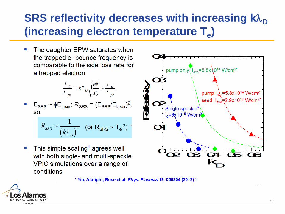
4
SRS reflectivity decreases with increasing kλD (increasing electron temperature Te)

5
Magnetic insulation can lead to increased hohlraum plasma temperatures
adapted from “Physics of Laser Fusion, Vol. 1”, C.E. Max, UCRL-53107 (1982)
Bz
electron Larmor radius ρL = mev/eB
electron-ion collision m.f.p.
λei ≈ vth/νei
when ρL < λei transport across magnetic field is reduced since
ρL sets the transport step size
Braginskii heat flux†
“insulation” occurs when:
† ignoring cross-terms

6
Scaling from previous experiments suggests Bz ~ 10-T may increase Te in gas-filled hohlraums
T e a
t 1-n
s (k
eV)
Magnetized Gasjet Experiments*
* Froula et al., PRL (2007)
gasjet parameters
250 eV
1.5e19 e/cm3
~ 5 (N2)
10 T
NIF parameters
2 – 2.5 keV
1e21 e/cm3
2 – 3.5 (He or CH)
10-12 T
Te
Bz
Z
ne
We expect a temperature increase for magnetized NIF hohlraums

7
Experiments are performed at Omega using gas-filled hohlraums and an external B-field
10/23/2015
• 19-kJ of 3ω in 1-ns pulse (39 beams, 3 cones), gas-fill 0.95-atm 25% C5H12 + 75% CH4
• plasma conditions measured using 4ω Thomson scattering, delayed 0.3-ns
• external Bz applied using MIFEDS coil in a 400-ns pulse†
2.4 mm
1.6 mm
0.4 mm φ
P9
P4
Side view No MIFEDS coil
MIFEDS coil
Cones 1,2,3 drive beams
8-mm I.D.
16.65-mm O.D.
4ω probe
† Gotchev et al., Rev. Sci. Instrum. 80, 043504 (2009).
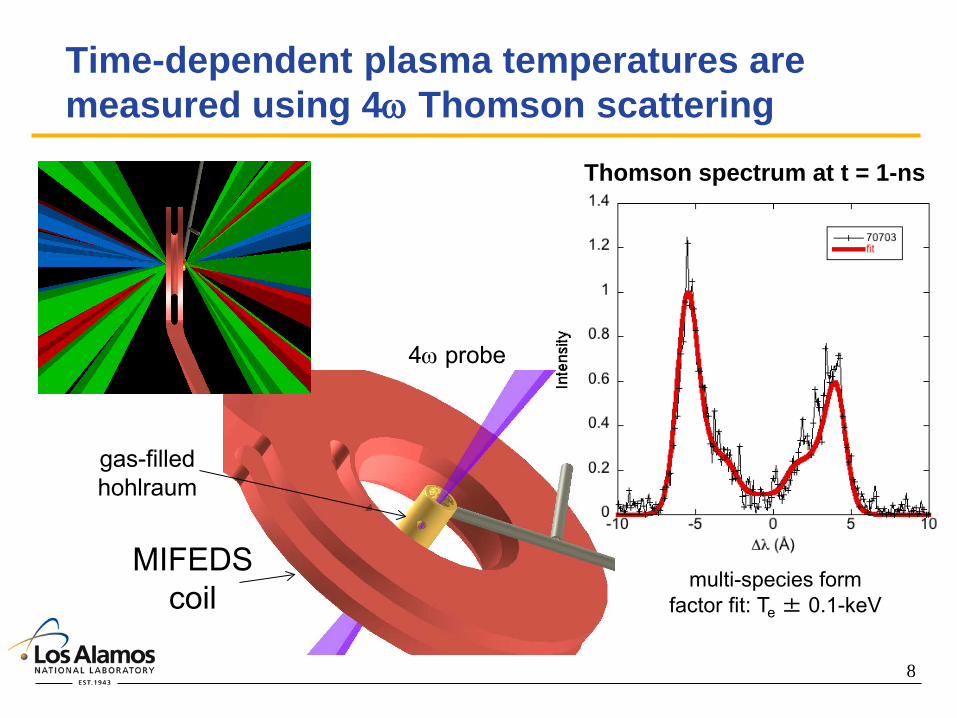
8
Time-dependent plasma temperatures are measured using 4ω Thomson scattering
MIFEDS coil
4ω probe
gas-filled hohlraum
Thomson spectrum at t = 1-ns
multi-species form factor fit: Te ± 0.1-keV
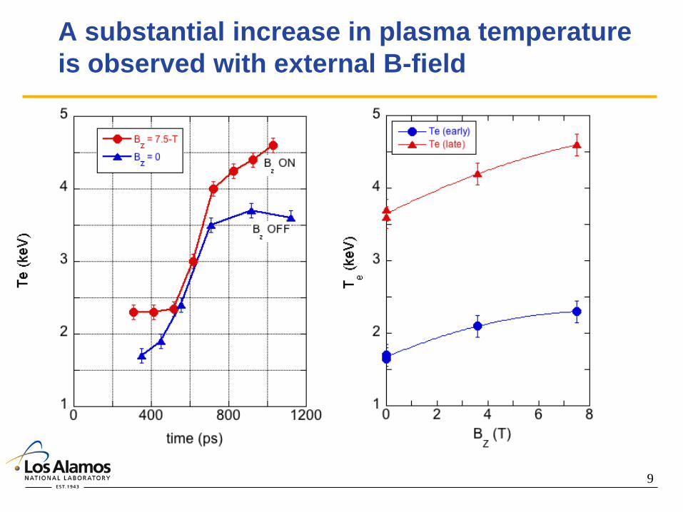
9
A substantial increase in plasma temperature is observed with external B-field
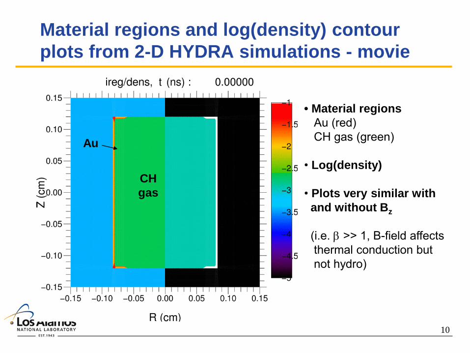
10
Material regions and log(density) contour plots from 2-D HYDRA simulations - movie
Au
CH gas
• Material regions Au (red) CH gas (green) • Log(density) • Plots very similar with and without Bz (i.e. β >> 1, B-field affects thermal conduction but not hydro)
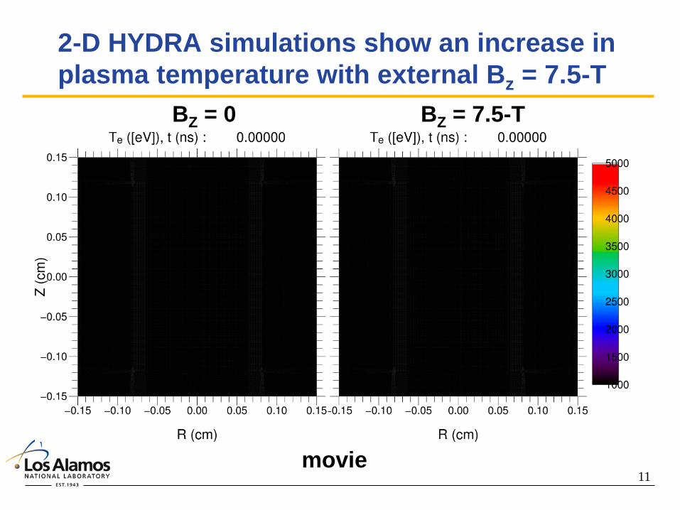
11
2-D HYDRA simulations show an increase in plasma temperature with external Bz = 7.5-T
BZ = 0 BZ = 7.5-T
movie

12
2-D HYDRA modeling is in good agreement with measured plasma temperatures†
• HYDRA model: - used measured laser parameters - flux limiter f = 0.05 - no self-fields - overall trends compare well - rapid temperature rise not captured at intermediate times (sampling region different between expt & model). † D.S. Montgomery et al., Phys. Plasmas (2015)
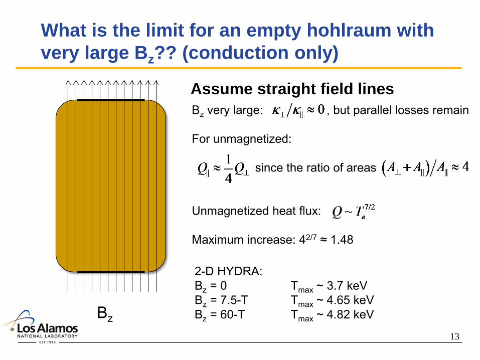
13
What is the limit for an empty hohlraum with very large Bz?? (conduction only)
Bz
Bz very large: , but parallel losses remain For unmagnetized: since the ratio of areas Unmagnetized heat flux: Maximum increase: 42/7 ≈ 1.48 2-D HYDRA: Bz = 0 Tmax ~ 3.7 keV Bz = 7.5-T Tmax ~ 4.65 keV Bz = 60-T Tmax ~ 4.82 keV
Assume straight field lines
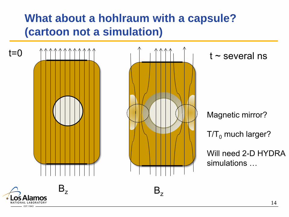
14
What about a hohlraum with a capsule? (cartoon not a simulation)
Bz Bz
t=0 t ~ several ns
Magnetic mirror? T/T0 much larger? Will need 2-D HYDRA simulations …

15
Summary and Conclusions
Increased underdense plasma temperatures are desirable for NIF ignition hohlraums - improve laser propagation through long-scale-length low-Z plasma
(less inverse bremsstrahlung absorption) - possibly mitigate LPI with higher Te (higher kλD, more Landau
damping)
Magnetic insulation can increase the plasma temperature with Bz ≥ 10-T in gas-filled hohlraums
Omega experiments using gas-filled hohlraums demonstrate an increased plasma temperature with Bz = 7.5-T - plasma conditions measured with 4ω Thomson scattering
- 2-D HYDRA simulations are in good agreement with experimental results

16
BACKUPS
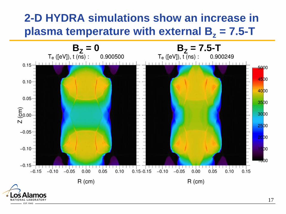
17
2-D HYDRA simulations show an increase in plasma temperature with external Bz = 7.5-T
BZ = 0 BZ = 7.5-T
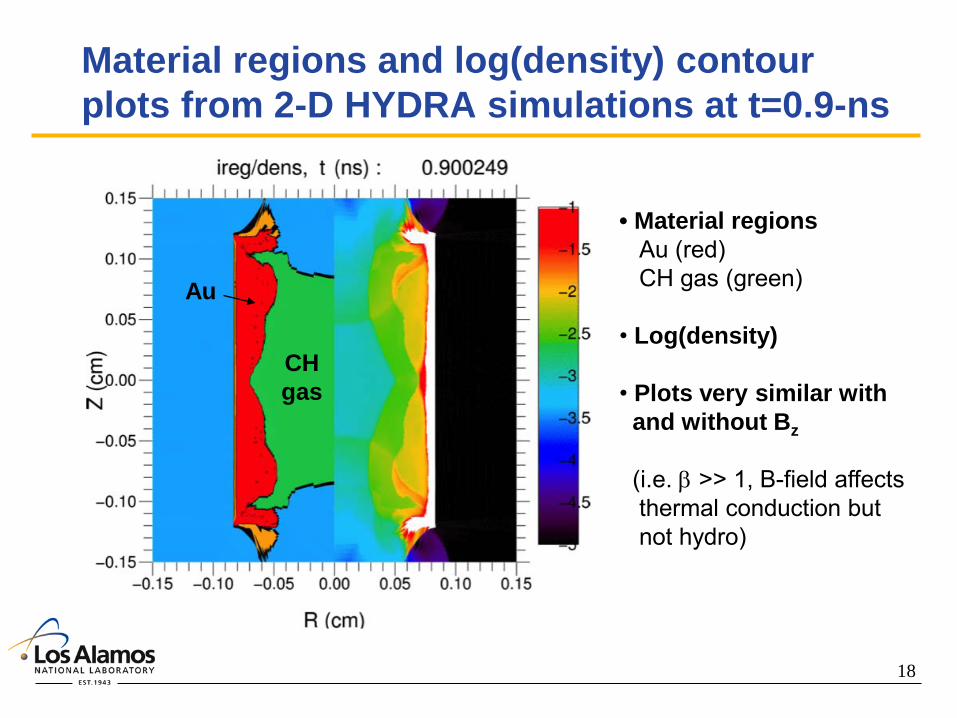
18
Material regions and log(density) contour plots from 2-D HYDRA simulations at t=0.9-ns
Au
CH gas
• Material regions Au (red) CH gas (green) • Log(density) • Plots very similar with and without Bz (i.e. β >> 1, B-field affects thermal conduction but not hydro)
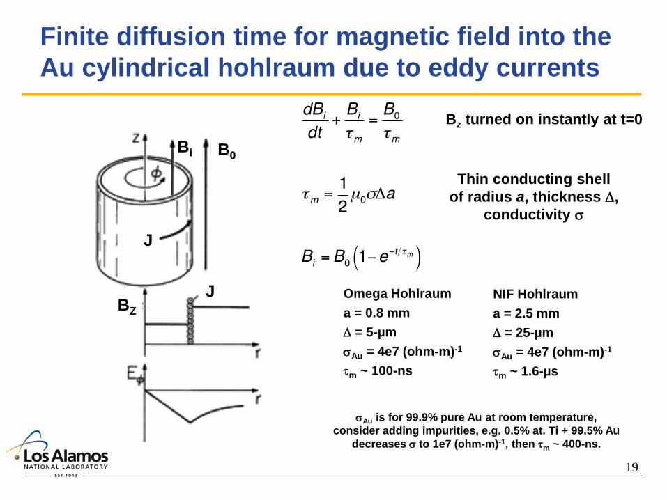
19
Finite diffusion time for magnetic field into the Au cylindrical hohlraum due to eddy currents
B0 Bi
J
J BZ
Thin conducting shell of radius a, thickness ∆,
conductivity σ
Omega Hohlraum a = 0.8 mm ∆ = 5-µm σAu = 4e7 (ohm-m)-1 τm ~ 100-ns
NIF Hohlraum a = 2.5 mm ∆ = 25-µm σAu = 4e7 (ohm-m)-1 τm ~ 1.6-µs
Bz turned on instantly at t=0
σAu is for 99.9% pure Au at room temperature, consider adding impurities, e.g. 0.5% at. Ti + 99.5% Au
decreases σ to 1e7 (ohm-m)-1, then τm ~ 400-ns.

LLNL-PRES-??? This work was performed under the auspices of the U.S. Department of Energy by Lawrence Livermore National Laboratory under contract DE-AC52-07NA27344. Lawrence Livermore National Security, LLC
Ignition Hohlraum Simulations with Imposed Magnetic Field, and Effect on Hot Electrons NIF Magnetic Field Workshop
12 October 2015 David J. Strozzi, J. M. Koning, L. J. Perkins,
M. M. Marinak, D. J. Larson, B. G. Logan

LLNL-PRES-??? 2
Summary: axial B field impacts hohlraum rad-hydro and hot electrons
• Axial field of 70 Tesla: goal for NIF
D. J. Strozzi et al., Journ. Plasma Physics (submitted), arxiv.org/abs/1508.00803
No B
Bz0 = 70 T
Raises temperature, esp. near wall e- temperature: with B - without B [keV]
Improves inner beam propagation: Increased equator x-ray drive
Hot electrons magnetized in fill gas: guided to or away from capsule
Z source = -0.2 cm
Z source = -0.25 cm
Hot e- energy deposition

LLNL-PRES-??? 3
Hydra MHD model: simple Ohm’s law, reduced heat conduction across B the main effect
( )( )
0
Faraday:
Ampère:
Mass continuity: 0
CM velocity:
t
t m m
m t
B E
J B
V
V V E pJ B
µ
ρ ρ
ρ ρ
∂ = −∇×
= ∇×
∂ +∇⋅ =
∂ + ⋅ ×∇ = + −∇
0: quasi-neutral
Single-fluid, quasi-neutral, “Ohmic”: no e- inertia or displacement current
1ee
e e
pJE v B B J e Tn e n e
v B J
η
η
β−∇= − × + × − + ⋅ − ⋅
× ⋅
∇
− +=
Ohm’s law: inertia-less e- momentum equation:
Full Braginskii 1965
Used in this work
Electron energy equation:
( )( ) 2||( ) ..ˆ ˆ .t e e ei i e
eeT Jd T p v T T
dTερ κξ κ κ η⊥ ⊥
∇⋅∂ + ∇⋅ = − ∇− − + + +bb I
Blue: how MHD / B field affect matter
Reduced conduction perp. to B
Ohmic heating
JxB force / magnetic pressure

LLNL-PRES-??? 4
e- heat conduction perpendicular to B strongly suppressed in underdense low-Z fill for B > 1 T
12 3
|| 2 3 4
11
Hall parameterdepend on Z
ce ei
i i
p Hp H p H p H
Hp
κκ
ω τ
⊥ +≈
+ + +
≡
Z=2 helium
O
ne = 0.1ncr Te = 3 keV B = 1.4 T
||/k k^
(1, 0.2)
Reduced perpendicular heat conduction: • Increases electron temperature • Improves inner beam propagation
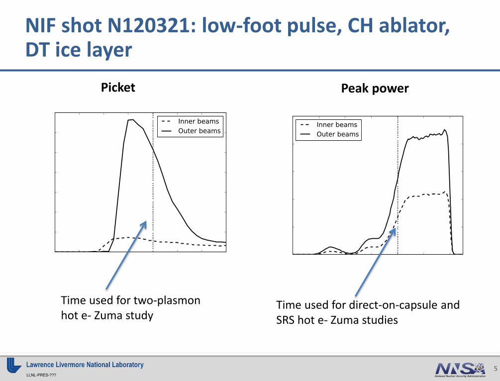
LLNL-PRES-??? 5
NIF shot N120321: low-foot pulse, CH ablator, DT ice layer
Picket Peak power
Time used for two-plasmon hot e- Zuma study
Time used for direct-on-capsule and SRS hot e- Zuma studies
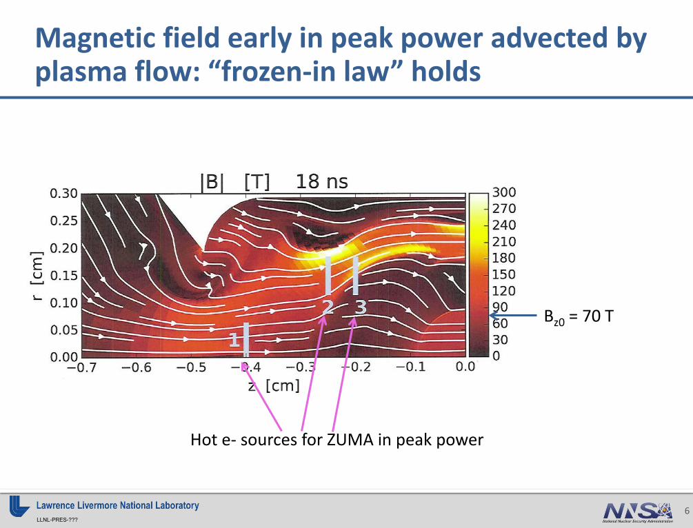
LLNL-PRES-??? 6
Magnetic field early in peak power advected by plasma flow: “frozen-in law” holds
Bz0 = 70 T
Hot e- sources for ZUMA in peak power
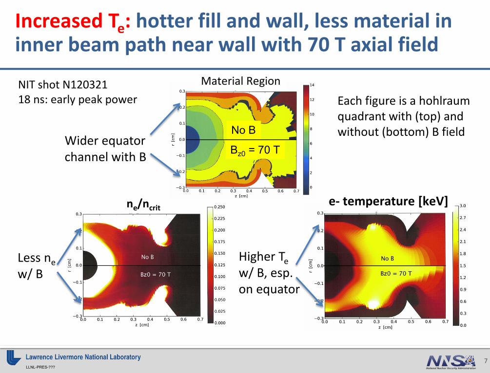
LLNL-PRES-??? 7
Increased Te: hotter fill and wall, less material in inner beam path near wall with 70 T axial field
e- temperature [keV] ne/ncrit
NIT shot N120321 18 ns: early peak power
No B
Bz0 = 70 T Wider equator channel with B
Less ne w/ B
Higher Te w/ B, esp. on equator
Material Region
Each figure is a hohlraum quadrant with (top) and without (bottom) B field

LLNL-PRES-??? 8
Increased Te: with B field, Te is 0.5 – 1.5 keV hotter near wall, < 0.5 keV in rest of fill
E- temperature difference at 18 ns: With B – without B [keV]
∆Te = 0.2 keV
0.5 keV
0.5 keV 1 keV
Hohlraum wall
18 ns: start of peak power

LLNL-PRES-??? 9
Te at various times: largest increase with field in gold
Region boundary
+0.5 keV
-0.5 keV

LLNL-PRES-??? 10
Inner beam propagation: B field reduces inner beam absorption in fill, less pancaked implosion
NIF Shot N120321: 21.5 ns: end of pulse • Shell radius ~ 150 um • No B: shell oblate (pancaked) • With B: close to round, better inner-beam propagation
No B
Bz0 = 70 T
Hohlraum axis
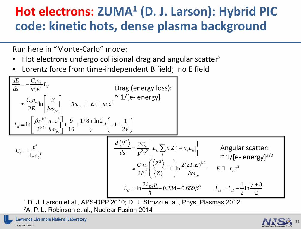
LLNL-PRES-??? 11
Hot electrons: ZUMA1 (D. J. Larson): Hybrid PIC code: kinetic hots, dense plasma background
Run here in “Monte-Carlo” mode: • Hot electrons undergo collisional drag and angular scatter2
• Lorentz force from time-independent B field; no E field
1 D. J. Larson et al., APS-DPP 2010; D. J. Strozzi et al., Phys. Plasmas 2012 2A. P. L. Robinson et al., Nuclear Fusion 2014
Drag (energy loss): ~ 1/[e- energy]
2
2
21/2
1/2
ln2
9 1/ 8 ln 2 1ln * 12 16 2
e ed
e
e epe e
pe
ed
pe
C ndE Lds m v
C n E E m cE
m cL
ωω
βεω γ γ
= −
≈
+
= + + − +
4
204e
eCπε
≡ Angular scatter: ~ 1/[e- energy]3/2
22
2 2
2 1/22
2
2
2
2(2 )1 ln2
2 1 3ln 0.234 0.659 ln2 2
esI i i e se
i
e e ee
pe
DesI se sI
d C L n Z n Lds p v
ZC n T E E m cE Z
pL L L
θ
ω
λ γβ
= +
≈ +
+= − − = −
∑
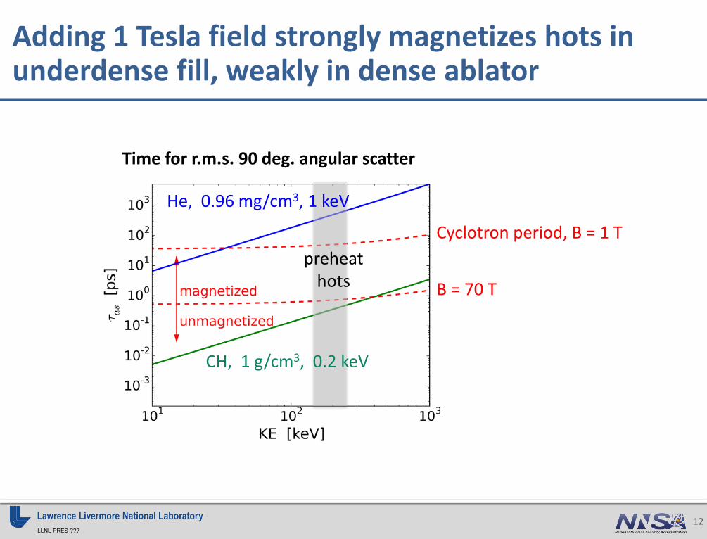
LLNL-PRES-??? 12
Adding 1 Tesla field strongly magnetizes hots in underdense fill, weakly in dense ablator
Cyclotron period, B = 1 T
Time for r.m.s. 90 deg. angular scatter
B = 70 T
CH, 1 g/cm3, 0.2 keV
He, 0.96 mg/cm3, 1 keV
preheat hots
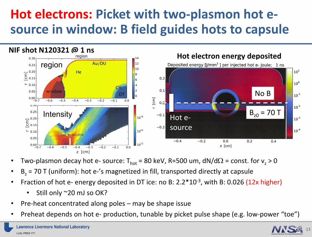
LLNL-PRES-??? 13
Hot electrons: Picket with two-plasmon hot e- source in window: B field guides hots to capsule NIF shot N120321 @ 1 ns
• Two-plasmon decay hot e- source: Thot = 80 keV, R=500 um, dN/dΩ = const. for vz > 0 • Bz = 70 T (uniform): hot e-’s magnetized in fill, transported directly at capsule • Fraction of hot e- energy deposited in DT ice: no B: 2.2*10-3, with B: 0.026 (12x higher)
• Still only ~20 mJ so OK? • Pre-heat concentrated along poles – may be shape issue • Preheat depends on hot e- production, tunable by picket pulse shape (e.g. low-power “toe”)
Hot electron energy deposited
No B
Bz0 = 70 T Hot e- source
region
Intensity

LLNL-PRES-??? 14
Bz0 = 70 T
B field lines roughly follow MHD frozen-in law: advected with conducting plasma N120321, 18 ns: early peak power
• Field increases where compressed between ablator and wall • Some field lines connect to capsule, some don’t SRS source: • Thot = 30 keV • Angle spectrum: dN/dΩ = exp[-((θ-27o)/10o)4]
Critical field line: • Inside lines connect to
capsule • Outside lines don’t
ZUMA Hot e- sources

LLNL-PRES-??? 15
Hot electrons: coupling to DT early in peak power is very sensitive to source location Coupled energy [J/mm3] per injected hot e- Joule
Source No B Bz0 = 70 T
Bz0 / no B
1 3.58E-4 2.89E-3 8.07 2 1.37E-4 3.44E-6 0.025 3 1.19E-4 1.26E-3 10.6
Fraction of hot e- energy coupled to DT ice
Z source = -0.25 cm
Z source = -0.4 cm
Z source = -0.2 cm
3
2 1

LLNL-PRES-??? 16
Conclusion: imposed B field may improve inner beam propagation, could help or hurt hot electron preheat Hydra MHD simulation of low-foot shot N120321, with 70 T initial axial field: • Cross-field electron heat conduction greatly reduced • Leads to hotter and less dense equator, better inner-beam propagation • May reduce inner-beam SRS Zuma studies of hot electron propagation: • Picket: two-plasmon source in window guided to capsule, energy coupled to DT
12x higher • Peak power: SRS source confined to He fill, energy coupled to DT strongly
depends on source location • Story may change if hot electrons made no field lines still connected to capsule
Future work: • “Biermann” self-generated fields: numerics being investigated • Nernst effect may significantly affect imposed-field dynamics (A. Joglekar, PRL
2014 and Anomalous Absorption 2015)
LLNL-PRES-??? 17
BACKUP BELOW HERE

LLNL-PRES-??? 18
Hot electron test case: source directly incident on capsule
N120321 18 ns: early peak power
ne
Energy deposited per volume E = 175 keV
No angular scatter
Yes angular scatter
Unphysical test source: Mono-energetic, collimated
hots beam through
hots scatter In ablator
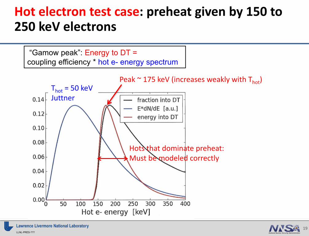
LLNL-PRES-??? 19
Hot electron test case: preheat given by 150 to 250 keV electrons
Thot = 50 keV Juttner
Peak ~ 175 keV (increases weakly with Thot)
“Gamow peak”: Energy to DT = coupling efficiency * hot e- energy spectrum
Hots that dominate preheat: Must be modeled correctly

LLNL-PRES-??? 20
Hot electron test case: E > 130 keV to reach DT, 185 keV couple best
130 keV to reach DT
185 keV couple best to DT

Experiment:
10/23/2015 2015 NIF B-field Workshop 1
2015 NIF B-field Workshop
Experiment: XRSD_Kshell_Bfield? Responsible Org: LLNL NIF shots from: XRSD/NSA? Shot RI: May/Moore? Engineer: Rhodes? Designer: Kemp/Colvin
Important aspects of the experiment: • Key B-field requirements: 10-50 T, 25%
uniformity, >10 µs rise time • Potentially more than double K-shell
emission in Kr/Ag/Xe targets • Enhancement can be tested with phased
increases in B
Experimental objectives: Increase plasma temperatures in low density, high-Z gas and foam targets to enhance multi-keV K-shell radiation used for x-ray sources Key physics related to having a B-field: Inhibited electron thermal transport with imposed magnetic fields Expected results: Enhanced K-shell emission, hotter x-ray spectra from Dante, NXS, SS-II and GXD
2 page Physics summary (1)
Enhancing multi-keV x-ray sources with B-fields
Bz
Dante-2
Dante-1
GXD/NXS/SS-II
GXD NXS
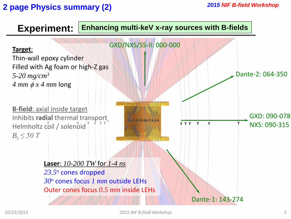
Dante-2: 064-350
Dante-1: 143-274
GXD: 090-078 NXS: 090-315
B-field: axial inside target Inhibits radial thermal transport Helmholtz coil / solenoid Bz ≤ 50 T
2 page Physics summary (2) 2015 NIF B-field Workshop
Experiment: Enhancing multi-keV x-ray sources with B-fields
Laser: 10-200 TW for 1-4 ns 23.5o cones dropped 30o cones focus 1 mm outside LEHs Outer cones focus 0.5 mm inside LEHs
Target: Thin-wall epoxy cylinder Filled with Ag foam or high-Z gas 5-20 mg/cm3
4 mm φ x 4 mm long
10/23/2015 2 2015 NIF B-field Workshop
GXD/NXS/SS-II: 000-000

This experiment requires a Bz ≤ 50 T and uniformity to 25%
10/23/2015 2015 NIF B-field Workshop 3
B-field magnitude Requirement: 2015 NIF B-field Workshop
50 T external Bz could double laser-driven 10-30 keV K-shell emission for otherwise underpowered interactions
Beneficial for either >20 keV sources which use all of NIF (SGEMP or materials effects
testing) or ~10 keV backlighters which only use a fraction of NIF
Uniformity requirements most stringent for lower field strengths: ±10% in X-ray yield (Dante uncertainty) corresponds to better than 25% uniformity @ 10 T, 50% @ 50 T
***HYDRA simulation results with resistive MHD package and constant external Bz***
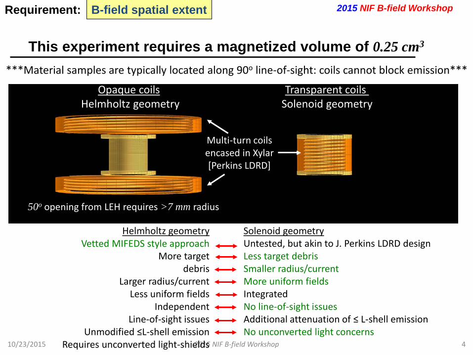
This experiment requires a magnetized volume of 0.25 cm3
10/23/2015 2015 NIF B-field Workshop 4
B-field spatial extent Requirement: 2015 NIF B-field Workshop
Opaque coils Helmholtz geometry
Transparent coils Solenoid geometry
50o opening from LEH requires >7 mm radius
Multi-turn coils encased in Xylar [Perkins LDRD]
Solenoid geometry Untested, but akin to J. Perkins LDRD design Less target debris Smaller radius/current More uniform fields Integrated No line-of-sight issues Additional attenuation of ≤ L-shell emission No unconverted light concerns
Helmholtz geometry Vetted MIFEDS style approach
More target debris
Larger radius/current Less uniform fields
Independent Line-of-sight issues
Unmodified ≤L-shell emission Requires unconverted light-shields
***Material samples are typically located along 90o line-of-sight: coils cannot block emission***
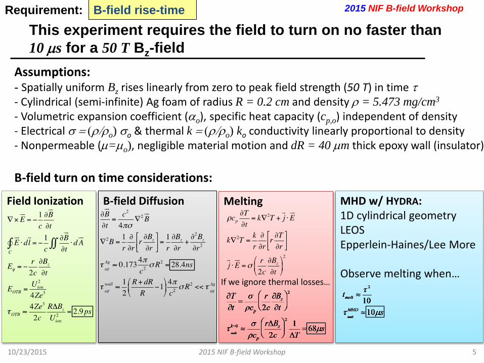
This experiment requires the field to turn on no faster than 10 µs for a 50 T Bz-field
10/23/2015 2015 NIF B-field Workshop 5
B-field rise-time Requirement: 2015 NIF B-field Workshop
Assumptions: - Spatially uniform Bz rises linearly from zero to peak field strength (50 T) in time τ - Cylindrical (semi-infinite) Ag foam of radius R = 0.2 cm and density ρ = 5.473 mg/cm3 - Volumetric expansion coefficient (αo), specific heat capacity (cp,o) independent of density - Electrical σ = (ρ/ρo) σo & thermal k = (ρ/ρo) ko conductivity linearly proportional to density - Nonpermeable (µ=µo), negligible material motion and dR = 40 µm thick epoxy wall (insulator)
B-field turn on time considerations:
B-field Diffusion
Field Ionization
Melting
If we ignore thermal losses…
MHD w/ HYDRA: 1D cylindrical geometry LEOS Epperlein-Haines/Lee More Observe melting when…
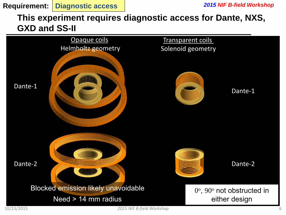
This experiment requires diagnostic access for Dante, NXS, GXD and SS-II
10/23/2015 2015 NIF B-field Workshop 6
Diagnostic access Requirement: 2015 NIF B-field Workshop
0o, 90o not obstructed in either design
Dante-1
Dante-2
Dante-1
Dante-2
Blocked emission likely unavoidable Need > 14 mm radius
Opaque coils Helmholtz geometry
Transparent coils Solenoid geometry

Alternatively, Bφ can provide both radial and axial insulation
10/23/2015 2015 NIF B-field Workshop 7
Alternative designs Requirement: 2015 NIF B-field Workshop
No line-of-sight issues
Laser-driven fields likely less uniform than current-driven
Harder to get ~10 T fields with
single wire
Axial current
Short-pulse: ~MG fields
Bφ Iz
May be possible to achieve nearly total thermal insulation with Bφ ~ 30-50 T
Thermal (0-1.5 keV) L-shell (1.5-4 keV) K-shell (12-20 keV)
Bφ Bz
Thermal conductivity off
Bz can increase peak Te by ~50%, Bφ by ~100%

Other issues
10/23/2015 2015 NIF B-field Workshop 8
Other issues Requirement:
Machine safety considerations (debris, laser damage, backscatter, diagnostic damage risk, etc) • Likely reduced backscatter risk from enhanced Landau
damping at increased temperatures • Increased debris risk with Helmholtz coils There aren’t currently any vetted diagnostics/calibrations for Ag K-shell measurements
2015 NIF B-field Workshop
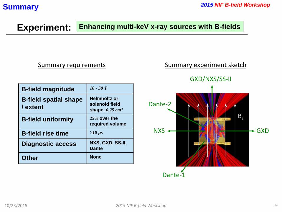
Experiment:
10/23/2015 2015 NIF B-field Workshop 9
Enhancing multi-keV x-ray sources with B-fields
Summary
Summary experiment sketch
B-field magnitude 10 - 50 T
B-field spatial shape / extent
Helmholtz or solenoid field shape, 0.25 cm3
B-field uniformity 25% over the required volume
B-field rise time >10 µs
Diagnostic access NXS, GXD, SS-II, Dante
Other None
Summary requirements
2015 NIF B-field Workshop
Bz
Dante-2
Dante-1
GXD NXS
GXD/NXS/SS-II

Experiment:
10/23/2015 2015 NIF B-field Workshop 1
Magnetized preheat for MagLIF using 20-30 kJ
2015 NIF B-field Workshop
Experiment: MagLIF on NIF Responsible Org: LLNL/SNL NIF shots from: Program Shot RI: Name of person Engineer: Person / organization
Important aspects of the experiment: • 30 T peak field, ≤ 30% uniformity
(future goal ≤ 10%) • Available for shots in 18-24 months • Can be done in phased approach
starting at 10 T, but data return and results improve with higher field
Experimental objectives: Measure effect of B field on plasma temperature and lifetime Key physics related to having a B-field: Suppress thermal conduction losses of preheated plasma Expected results: Increased electron temperature during preheat phase when ωτ>1, and increased plasma lifetime
2 page Physics summary (1)
Summary experiment sketch
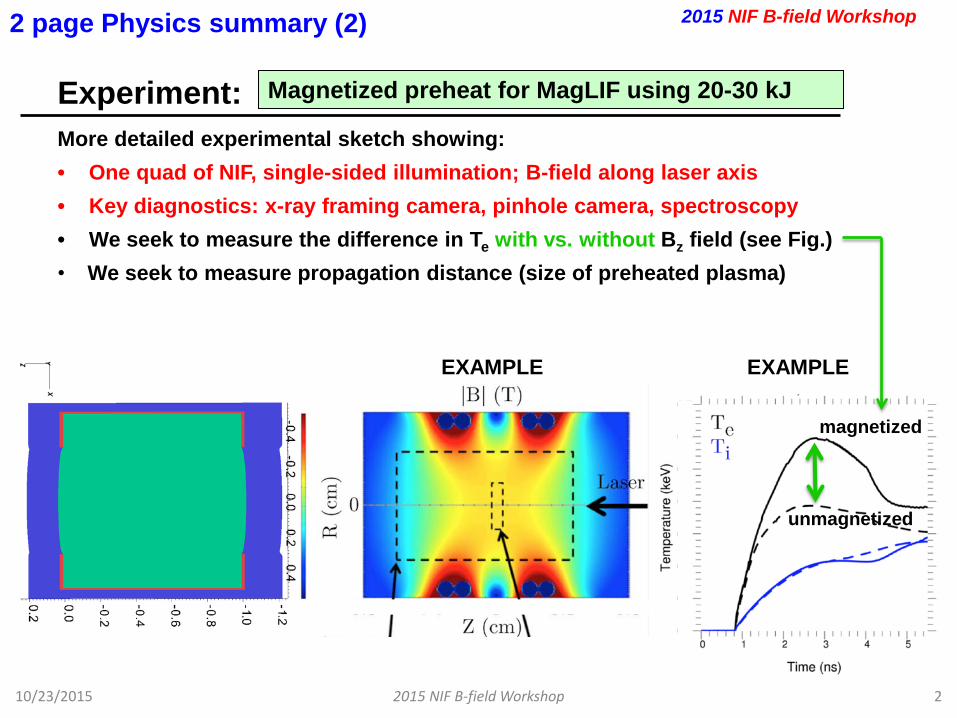
Experiment:
10/23/2015 2015 NIF B-field Workshop 2
2 page Physics summary (2)
More detailed experimental sketch showing: • One quad of NIF, single-sided illumination; B-field along laser axis • Key diagnostics: x-ray framing camera, pinhole camera, spectroscopy • We seek to measure the difference in Te with vs. without Bz field (see Fig.) • We seek to measure propagation distance (size of preheated plasma)
2015 NIF B-field Workshop
Magnetized preheat for MagLIF using 20-30 kJ
EXAMPLE EXAMPLE
magnetized
unmagnetized
This experiment requires a Bz ≥ 10 T and uniformity to ≤ 30%
10/23/2015 2015 NIF B-field Workshop 3
B-field magnitude Requirement:
B-field magnitude : 10 T initial, 30 T desired B-field spatial variation requirements : Solenoidal or Helmholtz field B-field spatial uniformity requirements : ≤ 30 % initial, ≤ 10 % desired • Required Bz spatial uniformity required for integrated (neutron-
producing) MagLIF is a work-in-progress. About 1% was achieved at Z, but this value is not known to be required.
2015 NIF B-field Workshop

This experiment requires a magnetized volume of ~0.8 cm3
10/23/2015 2015 NIF B-field Workshop 4
B-field spatial extent Requirement:
Approximate magnetized volume : Cylinder with V ~ 0.8 cm3 (ICF target limit: D = 1 cm, L = 1 cm, V = 0.785 cm3) Spatial shape of magnetized region : Cylinder Proposed source current path for achieving this : Helmoltz configuration to provide better diagnostic access to the main gas-pipe plasma
2015 NIF B-field Workshop
This experiment requires the field to turn on no faster than 24 µs (10 T) or 73 µs (30 T)
10/23/2015 2015 NIF B-field Workshop 5
B-field rise-time Requirement:
Rise-time determined by need to fully diffuse into target without deforming or otherwise compromising target integrity. Target tube thickness attenuates x-ray signal, so it (and its Z*) should be minimized. For 30 T peak field and 100 µm thick Be gas pipe tube: ≥ 73 µs For 10 T peak field and 100 µm thick Be gas pipe tube: ≥ 24 µs For ≤ 30 T peak field and CH gas-pipe: ≥ 2 µm (or driven by the heating rate in the pulsed-power delivery • Possibility for ~30% reduction with ~70 µm thick Be? • Possibility for reduction if tubes use thin CH, SiO2, etc., instead • Future target designs may involve small amounts of higher-Z
metal layers/contaminants for mix studies, but unlikely to raise requirement much
2015 NIF B-field Workshop

This experiment requires diagnostic access for these measurements…
10/23/2015 2015 NIF B-field Workshop 6
Diagnostic access Requirement: 2015 NIF B-field Workshop
Q31B laser
Transmission (witness plate or thin walled imaging)
10 mm
24 kJ 8 ns
Backscatter
Gated camera image (expected)
Spectroscopy data for Te (notional)
• Measure transmission, backscatter and Te
• Single quad, CPP, SSD, PS, 24 kJ in 8 ns: ~ 2x10¹⁴ W/cm2
• 2 shots: ne = 9 x 1020 cm-3 (10% ncr) and 4.5 x 1020 cm-3
A Helmholtz field configuration provides the best diagnostic access for this experiment
Single-quad experiment will require it’s own debris consideration
10/23/2015 2015 NIF B-field Workshop 7
Other issues Requirement:
Machine safety - debris: The experiment is a single quad (≤ 30 kJ). This low energy may create particle debris. Need to evaluate or consider “destroyer-pulse”
2015 NIF B-field Workshop
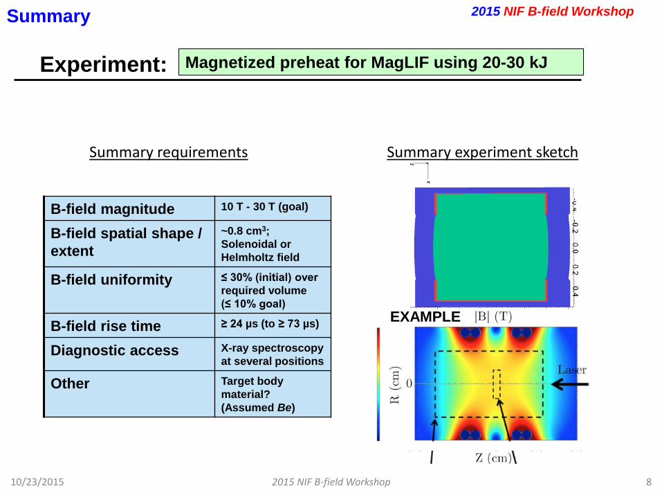
Experiment:
10/23/2015 2015 NIF B-field Workshop 8
Summary
B-field magnitude 10 T - 30 T (goal)
B-field spatial shape / extent
~0.8 cm3; Solenoidal or Helmholtz field
B-field uniformity ≤ 30% (initial) over required volume (≤ 10% goal)
B-field rise time ≥ 24 µs (to ≥ 73 µs)
Diagnostic access X-ray spectroscopy at several positions
Other Target body material? (Assumed Be)
Summary requirements
2015 NIF B-field Workshop
Magnetized preheat for MagLIF using 20-30 kJ
EXAMPLE
Summary experiment sketch
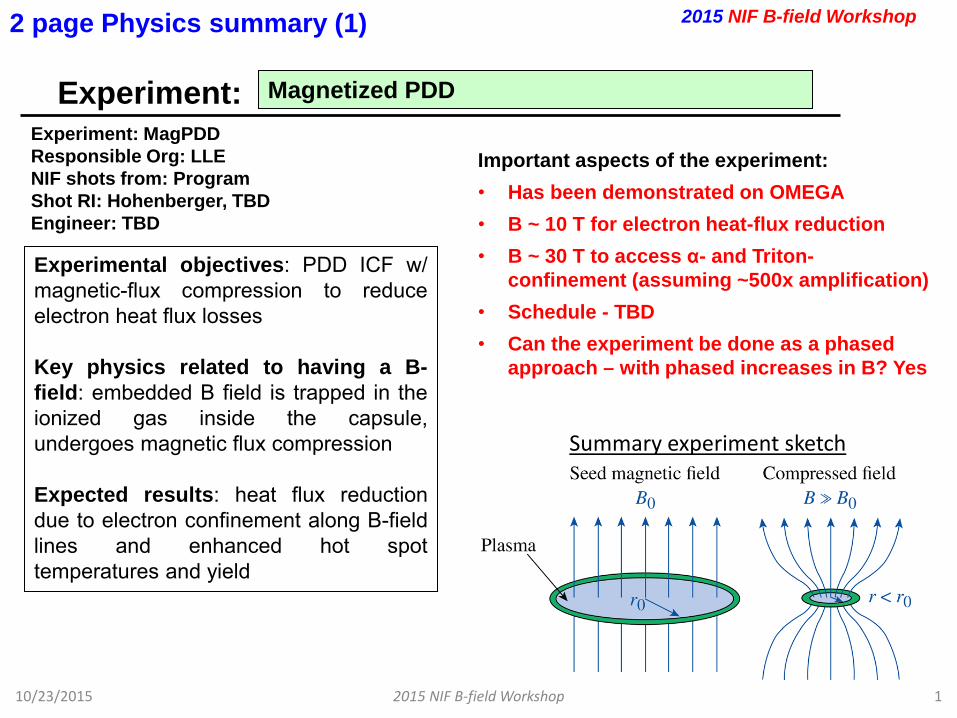
Experiment:
10/23/2015 2015 NIF B-field Workshop 1
Magnetized PDD
2015 NIF B-field Workshop
Experiment: MagPDD Responsible Org: LLE NIF shots from: Program Shot RI: Hohenberger, TBD Engineer: TBD
Important aspects of the experiment: • Has been demonstrated on OMEGA • B ~ 10 T for electron heat-flux reduction • B ~ 30 T to access α- and Triton-
confinement (assuming ~500x amplification) • Schedule - TBD • Can the experiment be done as a phased
approach – with phased increases in B? Yes
Experimental objectives: PDD ICF w/ magnetic-flux compression to reduce electron heat flux losses Key physics related to having a B-field: embedded B field is trapped in the ionized gas inside the capsule, undergoes magnetic flux compression Expected results: heat flux reduction due to electron confinement along B-field lines and enhanced hot spot temperatures and yield
2 page Physics summary (1)
Summary experiment sketch
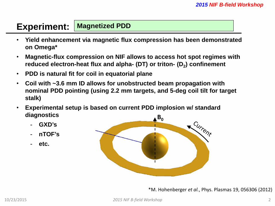
Experiment:
10/23/2015 2015 NIF B-field Workshop 2
Magnetized PDD
• Yield enhancement via magnetic flux compression has been demonstrated on Omega*
• Magnetic-flux compression on NIF allows to access hot spot regimes with reduced electron-heat flux and alpha- (DT) or triton- (D2) confinement
• PDD is natural fit for coil in equatorial plane • Coil with ~3.6 mm ID allows for unobstructed beam propagation with
nominal PDD pointing (using 2.2 mm targets, and 5-deg coil tilt for target stalk)
• Experimental setup is based on current PDD implosion w/ standard diagnostics
- GXD’s - nTOF’s - etc.
2015 NIF B-field Workshop
*M. Hohenberger et al., Phys. Plasmas 19, 056306 (2012)
B0
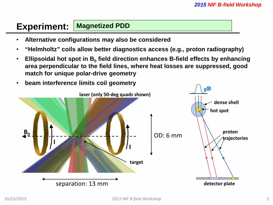
Experiment:
10/23/2015 2015 NIF B-field Workshop 3
Magnetized PDD
• Alternative configurations may also be considered • “Helmholtz” coils allow better diagnostics access (e.g., proton radiography) • Ellipsoidal hot spot in B0 field direction enhances B-field effects by enhancing
area perpendicular to the field lines, where heat losses are suppressed, good match for unique polar-drive geometry
• beam interference limits coil geometry
2015 NIF B-field Workshop
I I
B0
laser (only 50-deg quads shown)
target
OD: 6 mm
separation: 13 mm
dense shell
proton trajectories
detector plate
B
hot spot
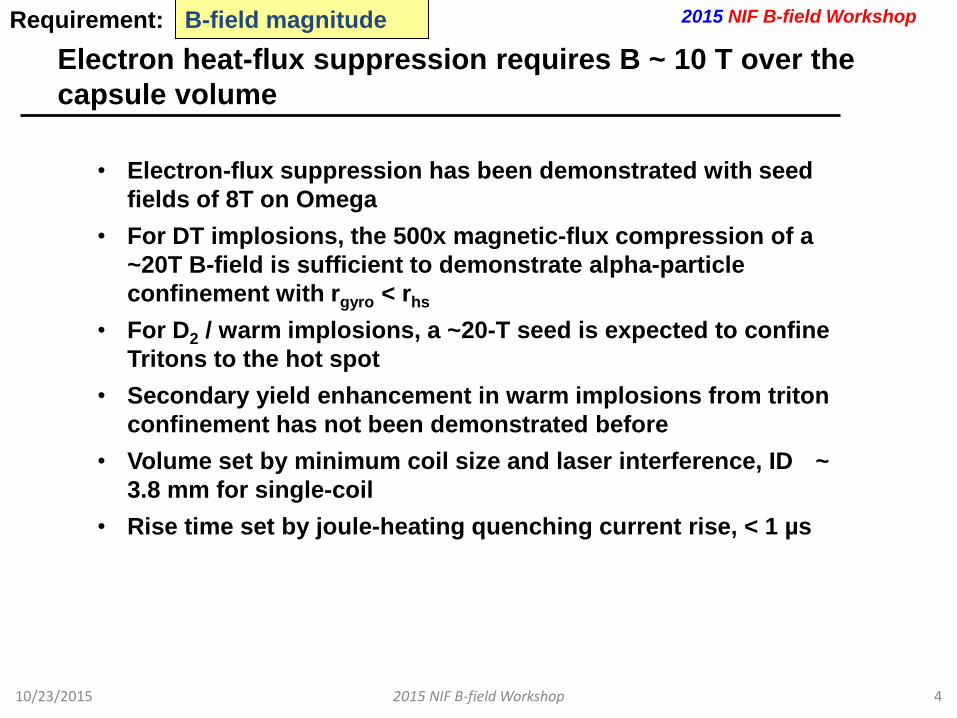
Electron heat-flux suppression requires B ~ 10 T over the capsule volume
10/23/2015 2015 NIF B-field Workshop 4
B-field magnitude Requirement:
• Electron-flux suppression has been demonstrated with seed fields of 8T on Omega
• For DT implosions, the 500x magnetic-flux compression of a ~20T B-field is sufficient to demonstrate alpha-particle confinement with rgyro < rhs
• For D2 / warm implosions, a ~20-T seed is expected to confine Tritons to the hot spot
• Secondary yield enhancement in warm implosions from triton confinement has not been demonstrated before
• Volume set by minimum coil size and laser interference, ID ~ 3.8 mm for single-coil
• Rise time set by joule-heating quenching current rise, < 1 µs
2015 NIF B-field Workshop

Experiment:
10/23/2015 2015 NIF B-field Workshop 5
Few word descriptive name of the experiment
Summary
Summary experiment sketch
B-field magnitude 10 - 30 T
B-field spatial shape / extent
single coil, dimensions set by beam interference, ~3.6 mm ID
B-field uniformity TBD
B-field rise time <1 µs
Diagnostic access nTOF line of sight
Other None
Summary requirements
2015 NIF B-field Workshop
B0 I
B0
I I
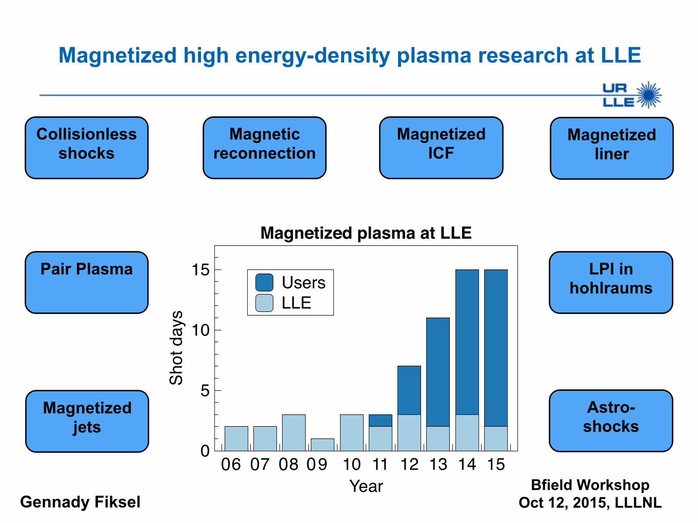
Magnetized high energy-density plasma research at LLE
Gennady FikselBfield Workshop
Oct 12, 2015, LLLNL
Magnetized ICF
LPI in hohlraums
Astro- shocks
Magnetized liner
Pair Plasma
Collisionless shocks
Magnetized jets
Magnetic reconnection
UsersLLE
Shot
day
s
0
5
10
15
Year6 7 8 9 10 11 12 13 14 15
Magnetized plasma at LLE
0 0 0 0

MIFEDS has opened a new frontier on magnetized HED plasma research on OMEGA
• Magnetized HED plasma research has greatly expanded during the last few years
• Magnetic field generator MIFEDS has become a facility diagnostic, widely used by LLE and Users
• MIFEDS flexible platform allows for wide variety of experimental configurations both on OMEGA and EP
• New and exciting results have been obtained in the areas of ICF, astrophysics-relevant applications, e-e+ pair production, and others
• Work ongoing on high-B platform development - from 10T to 30T to 50T
2
Summary
Collaborators
3
LLE Scientists: O. Gotchev, J. Knauer, R. Betti, P.-Y. Chang,
M. Hohenberger, J. Davies, D. Barnak S.X. Hu, P. Nilson
Engineers: A. Agliata, W. Bittle, G. Brent, D. Hasset, L. Folnsbee,
D. Lonobile, M. Shoup, C. Taylor
Users: W. Fox, A. Bhattacharjee, H. Chen, H.-S. Park, D. Montgomery,
and many others
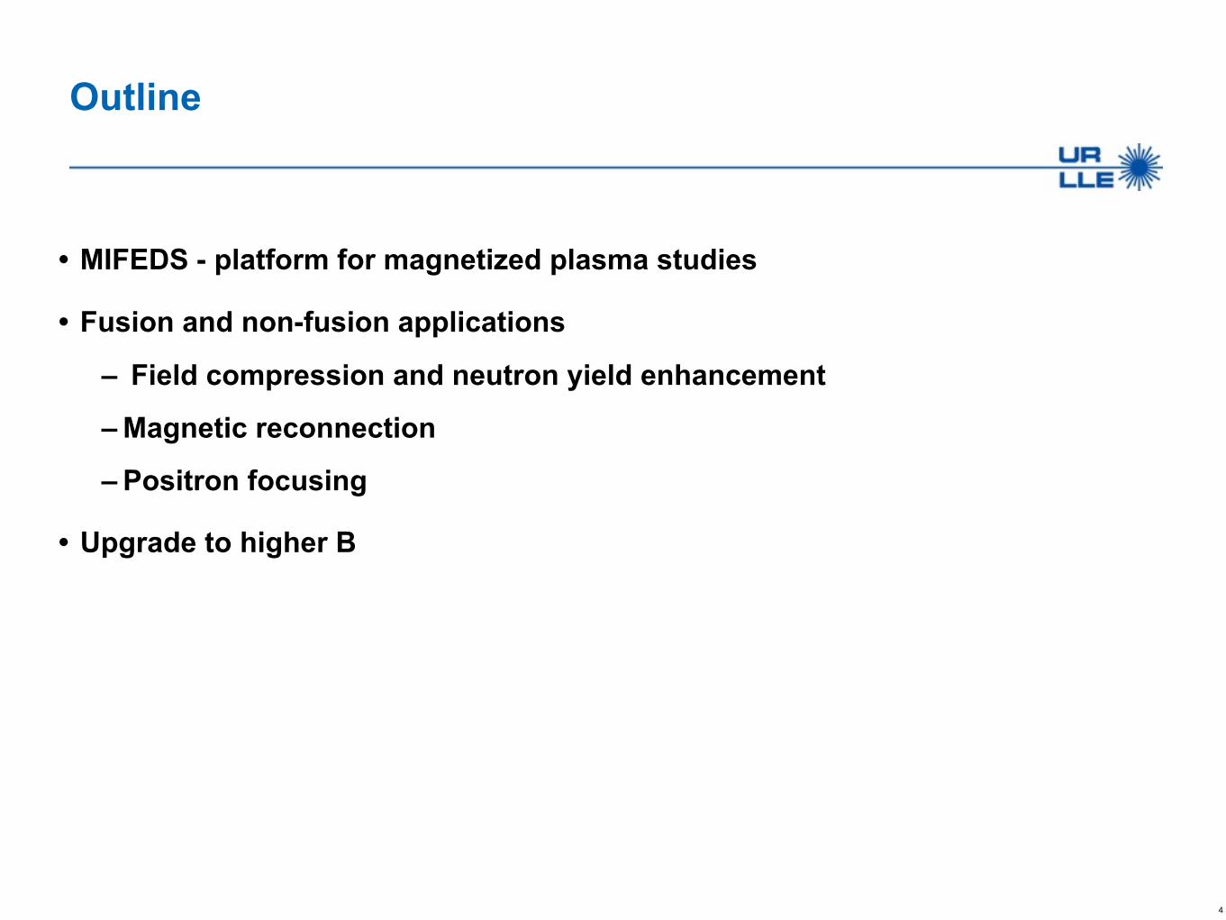
Outline
• MIFEDS - platform for magnetized plasma studies
• Fusion and non-fusion applications
– Field compression and neutron yield enhancement
– Magnetic reconnection
– Positron focusing
• Upgrade to higher B
4

- Listen, I’m having problems with MIFEDS...
- Sorry to hear that. Maybe you should see a doctor..
5
From an actual hallway conversation:
MIFEDS Magneto-Inertial Fusion Electrical Discharge System
TIM-based generator of pulsed magnetic field
The centerpiece for magnetized HED plasma research is MIFEDS
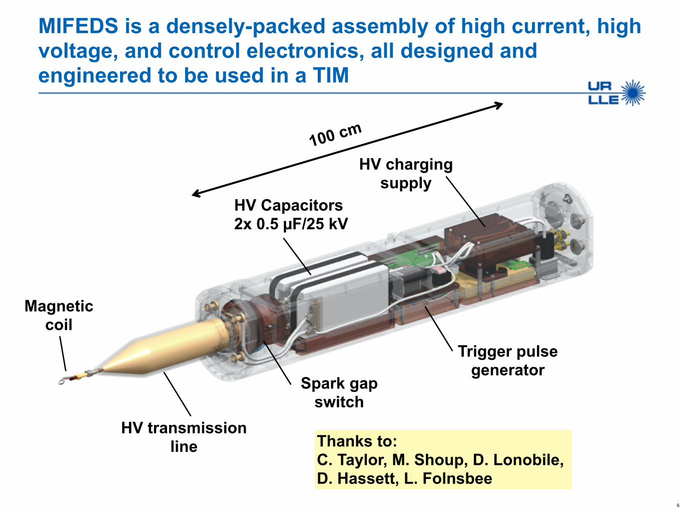
MIFEDS is a densely-packed assembly of high current, high voltage, and control electronics, all designed and engineered to be used in a TIM
6
HV charging supply
HV Capacitors 2x 0.5 µF/25 kV
Spark gap switch
HV transmission line
Magnetic coil
Thanks to: C. Taylor, M. Shoup, D. Lonobile, D. Hassett, L. Folnsbee
Trigger pulse generator
100 cm
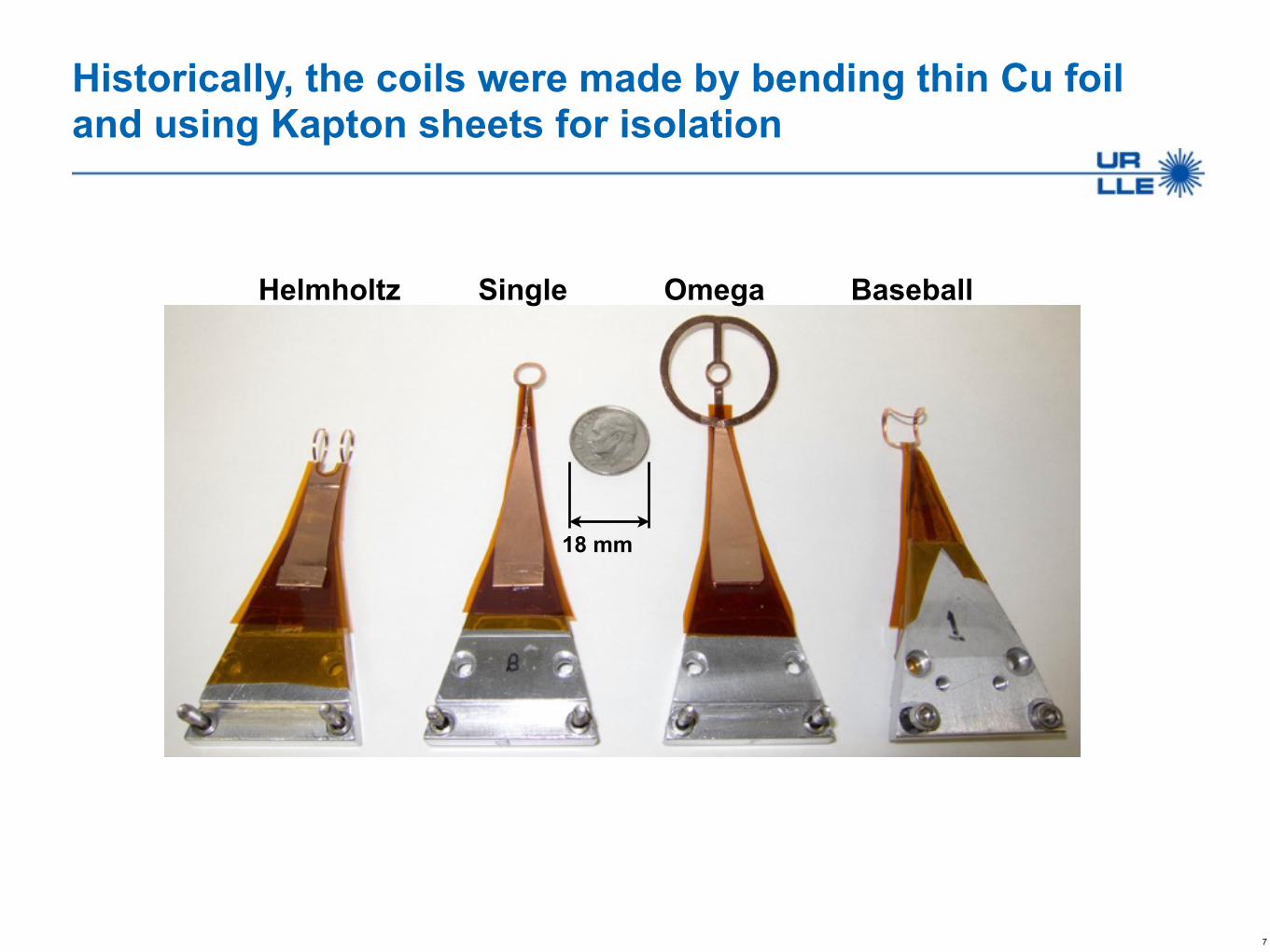
Historically, the coils were made by bending thin Cu foil and using Kapton sheets for isolation
7
Helmholtz Single Omega Baseball
18 mm
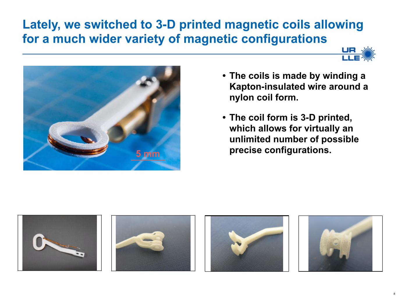
Lately, we switched to 3-D printed magnetic coils allowing for a much wider variety of magnetic configurations
8
• The coils is made by winding a Kapton-insulated wire around a nylon coil form.
• The coil form is 3-D printed, which allows for virtually an unlimited number of possible precise configurations.5 mm
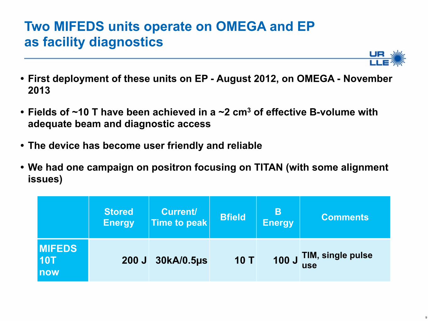
Two MIFEDS units operate on OMEGA and EP as facility diagnostics
• First deployment of these units on EP - August 2012, on OMEGA - November 2013
• Fields of ~10 T have been achieved in a ~2 cm3 of effective B-volume with adequate beam and diagnostic access
• The device has become user friendly and reliable
• We had one campaign on positron focusing on TITAN (with some alignment issues)
9
Stored Energy
Current/ Time to peak Bfield B
Energy Comments
MIFEDS 10T now
200 J 30kA/0.5µs 10 T 100 J TIM, single pulse use
Outline
• MIFEDS - platform for magnetized plasma studies
• Fusion and non-fusion applications
– Field compression and neutron yield enhancement
– Magnetic reconnection
– Positron focusing
• Upgrade to higher B
10
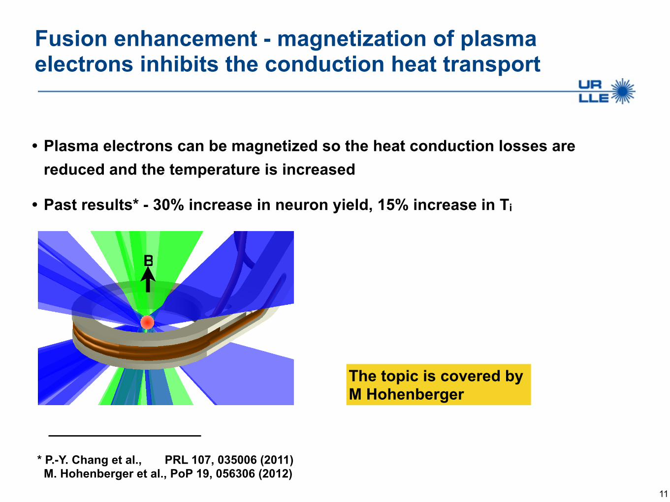
Fusion enhancement - magnetization of plasma electrons inhibits the conduction heat transport
• Plasma electrons can be magnetized so the heat conduction losses are reduced and the temperature is increased
• Past results* - 30% increase in neuron yield, 15% increase in Ti
11
* P.-Y. Chang et al., PRL 107, 035006 (2011) M. Hohenberger et al., PoP 19, 056306 (2012)
The topic is covered by M Hohenberger
B

Reconnection of an external B-field was studied by colliding two HED plasma bubbles
12
CH ablator
UV long pulse
IR short pulse
RCF pack
Multi-MeV proton beam
B-field of 8 T was created by magnetic coils powered by MIFEDS
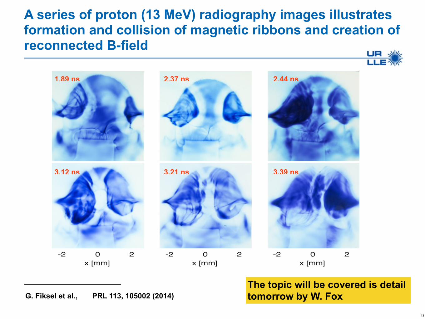
A series of proton (13 MeV) radiography images illustrates formation and collision of magnetic ribbons and creation of reconnected B-field
13
1.89 ns 2.37 ns 2.44 ns
3.12 ns 3.21 ns 3.39 ns
The topic will be covered is detail tomorrow by W. FoxG. Fiksel et al., PRL 113, 105002 (2014)
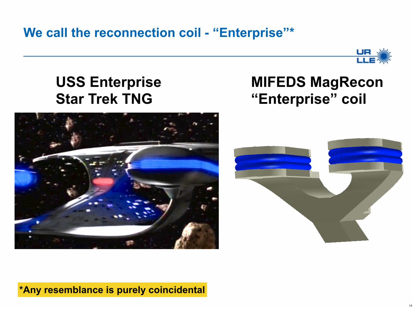
We call the reconnection coil - “Enterprise”*
14
USS Enterprise Star Trek TNG
MIFEDS MagRecon “Enterprise” coil
*Any resemblance is purely coincidental
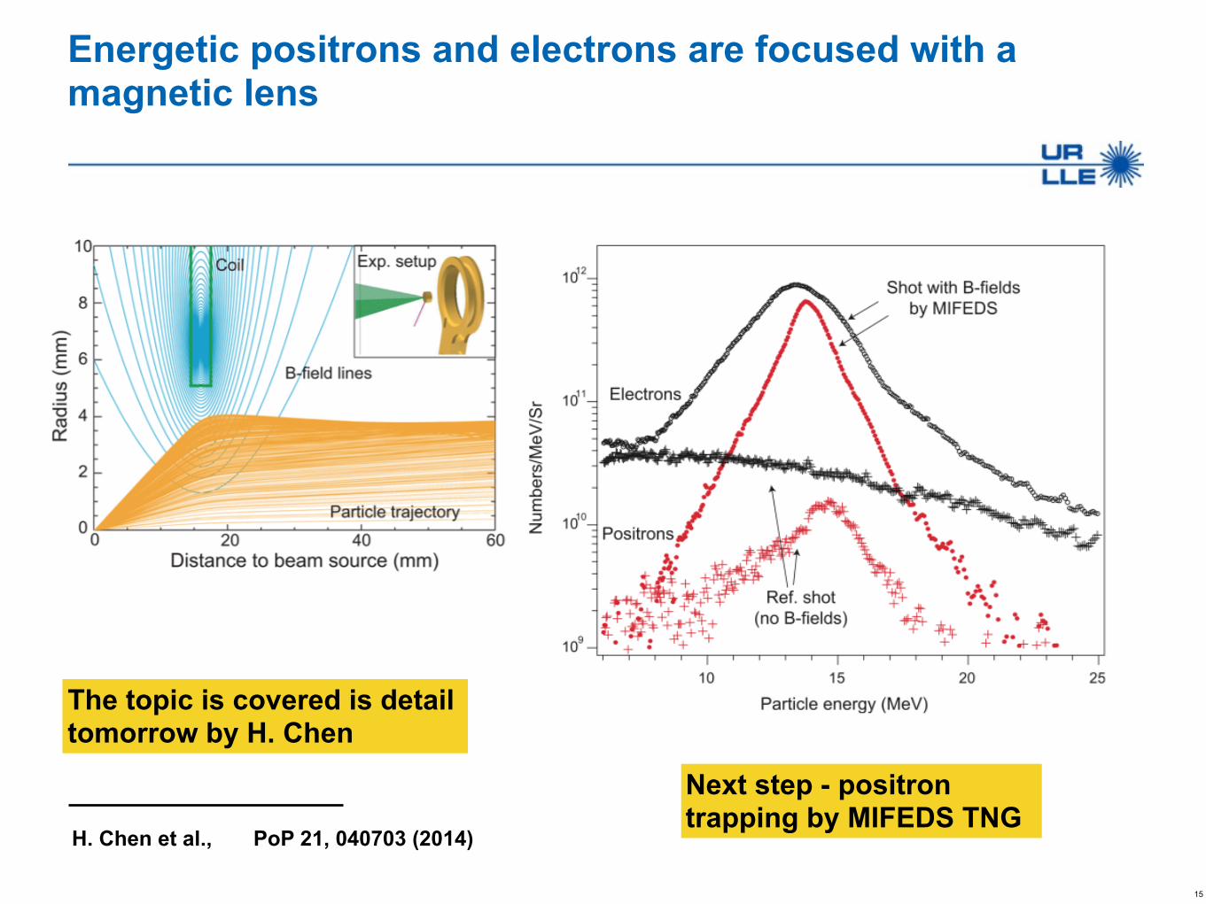
Energetic positrons and electrons are focused with a magnetic lens
15
The topic is covered is detail tomorrow by H. Chen
H. Chen et al., PoP 21, 040703 (2014)
Next step - positron trapping by MIFEDS TNG

Outline
• MIFEDS - platform for magnetized plasma studies
• Fusion and non-fusion applications
– Field compression and neutron yield enhancement
– Magnetic reconnection
– Positron focusing
• Upgrade to higher B
16
A high magnetic field is beneficial for many experiments - LLE and Users
• Fusion enhancement - spherical implosions, MAGLIF
• Magnetic reconnection - B (Lundquist)scaling
• Astrophysical shocks and jets - achieving Pplasma/PB ~1
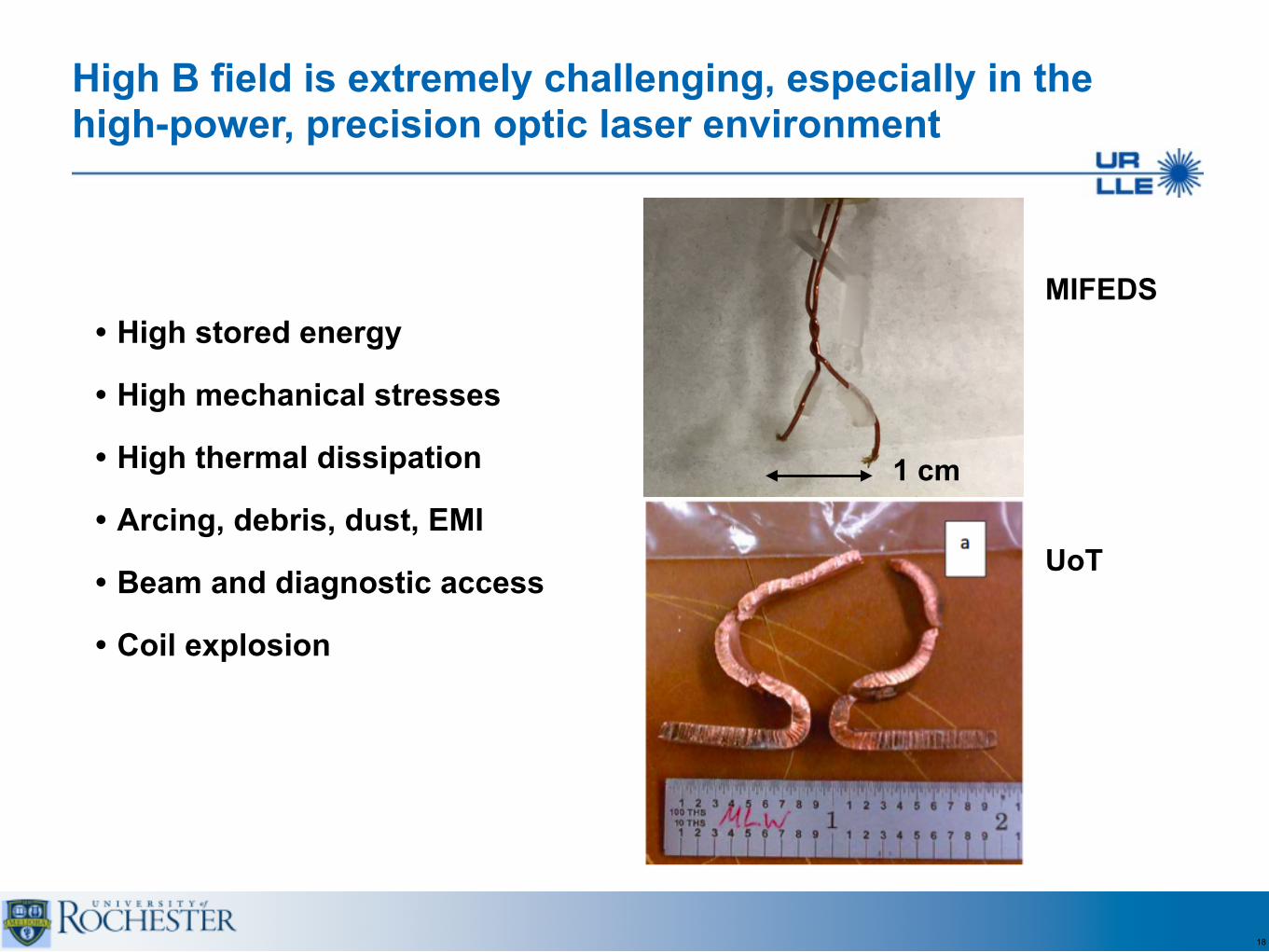
High B field is extremely challenging, especially in the high-power, precision optic laser environment
• High stored energy
• High mechanical stresses
• High thermal dissipation
• Arcing, debris, dust, EMI
• Beam and diagnostic access
• Coil explosion
18
MIFEDS
UoT
1 cm

High B field requires high stored energy and results in high mechanical stresses which are ~B2
19
Cu limit
Ener
gy (
kJ/c
m3 )
0
0.2
0.4
0.6
0.8
1.0
Pressure (MPa)
0
200
400
600
800
1000
B (T)0 20 40
• At 50T, B-pressure is 1000 MPa (10,000 atm)
• Copper ultimate tensile stress is 220 MPa => 25T-30T limit
• For short pulses ≤ 1µs, a coil can be free-standing - inertially supported
• For longer pulses, encasing is required
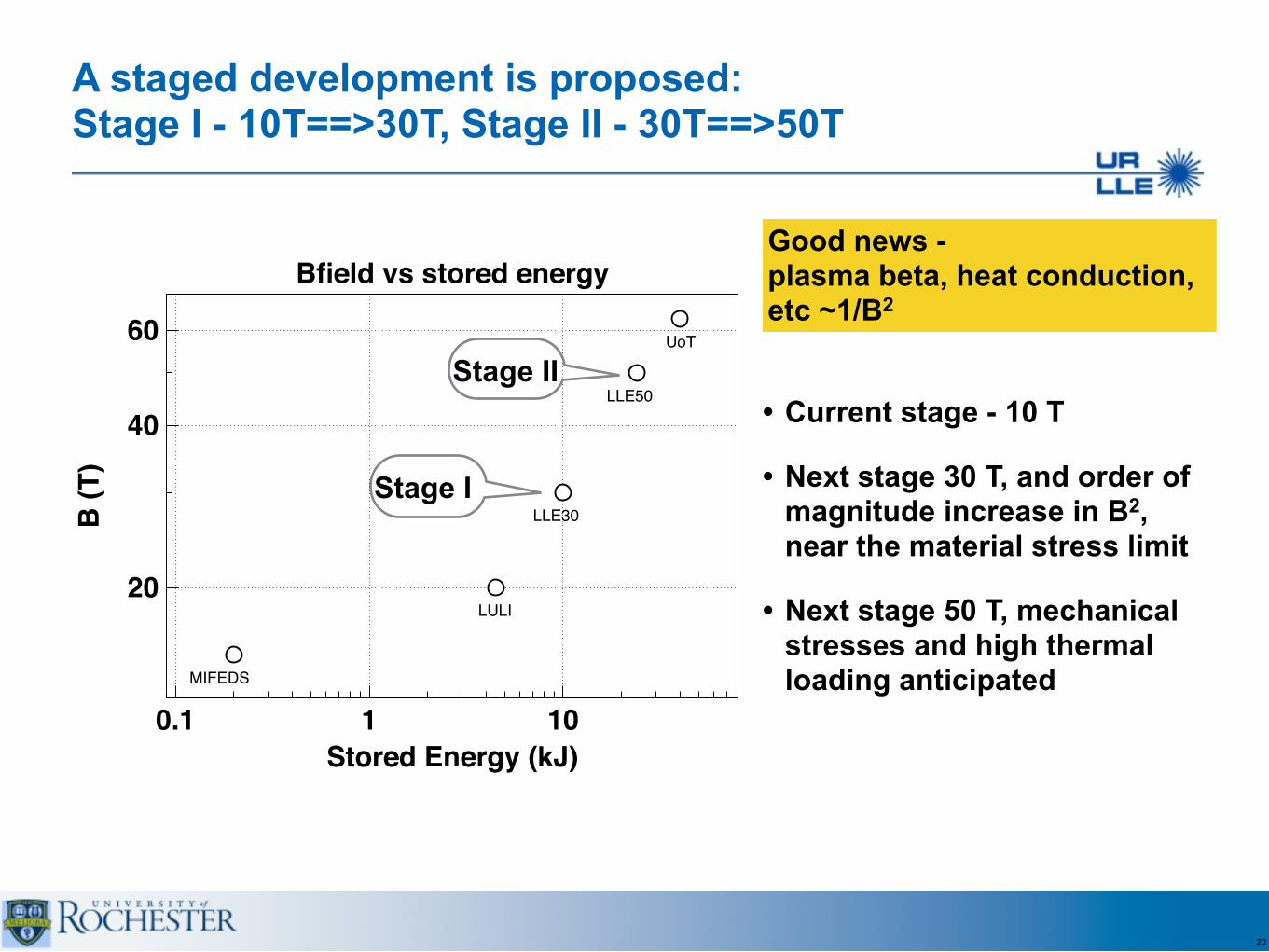
A staged development is proposed: Stage I - 10T==>30T, Stage II - 30T==>50T
20
Stage I
LULI
MIFEDS
UoT
LLE50
LLE30B (T
)
20
40
60
Stored Energy (kJ)0.1 1 10
Bfield vs stored energy
Stage II• Current stage - 10 T
• Next stage 30 T, and order of magnitude increase in B2, near the material stress limit
• Next stage 50 T, mechanical stresses and high thermal loading anticipated
Good news - plasma beta, heat conduction, etc ~1/B2

• Kapton insulated Cu wire 1mm dia, 9 turns
• The wire is encased into an enclosure
• Enclosure must be either non-conductive (epoxy? plastic? ceramic?) or have slits to eliminate the eddy currents
21
Possible coil design approach - multi-turn, encased. Requires 50 kA to produce 30 T in a ~5 mm dia volume
I = 50 kA
B (T
)
0
10
20
30
z (mm)−4 −2 0 2 4
B
Enclosure
Wire
5 mm
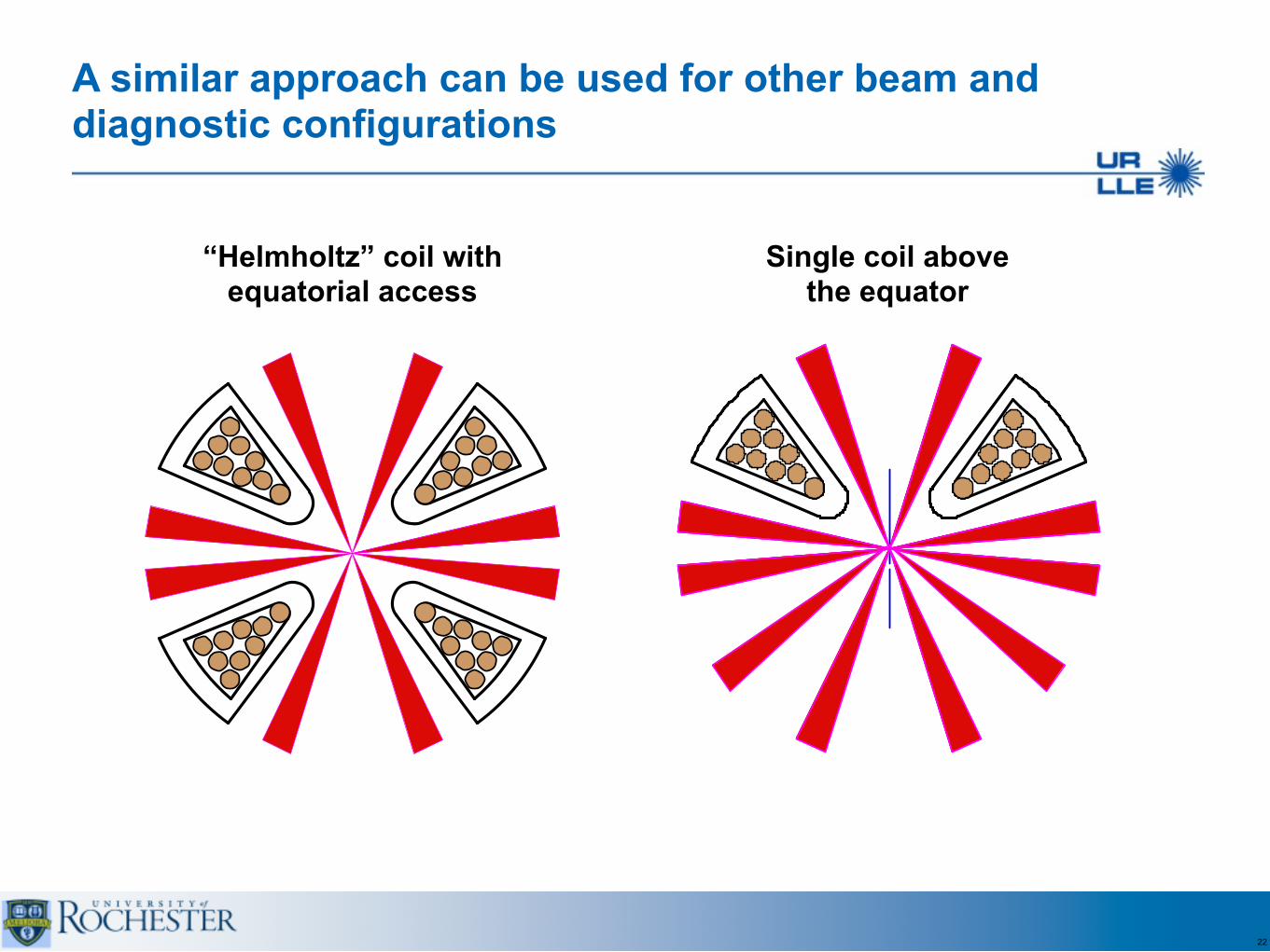
A similar approach can be used for other beam and diagnostic configurations
22
“Helmholtz” coil with equatorial access
Single coil above the equator
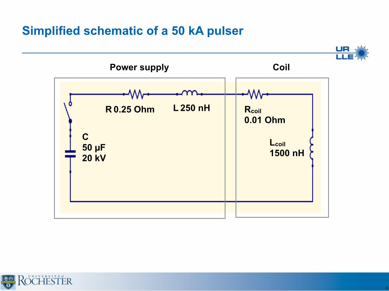
Simplified schematic of a 50 kA pulser
23
C 50 µF 20 kV
Power supply Coil
R 0.25 Ohm
Lcoil 1500 nH
L 250 nH Rcoil 0.01 Ohm

The coil thermal dissipation is manageable
• At the current peak, the coil is heated up to 150 °C
• The wire stays below 50% of melting temperature for the entire pulse duration
24
Stored energy 10 kJ Bfield energy 2 kJ Coil dissipation 0.75 kJ
Current
Temperature
Cur
rent
(kA
)
0
10
20
30
40
50
Temperature (C
)
0
100
200
300
400
500
600
Time (µs)0 10 20 30 40 50

Off the shelf capacitors and switches can be used
25
GA 33593 - 50µF/20kV/50kA GA 33694 - 2x 50µF/20kV/50kA
Perking-Elmer triggered spark gaps
• Used in MIFEDS
• Very reliable
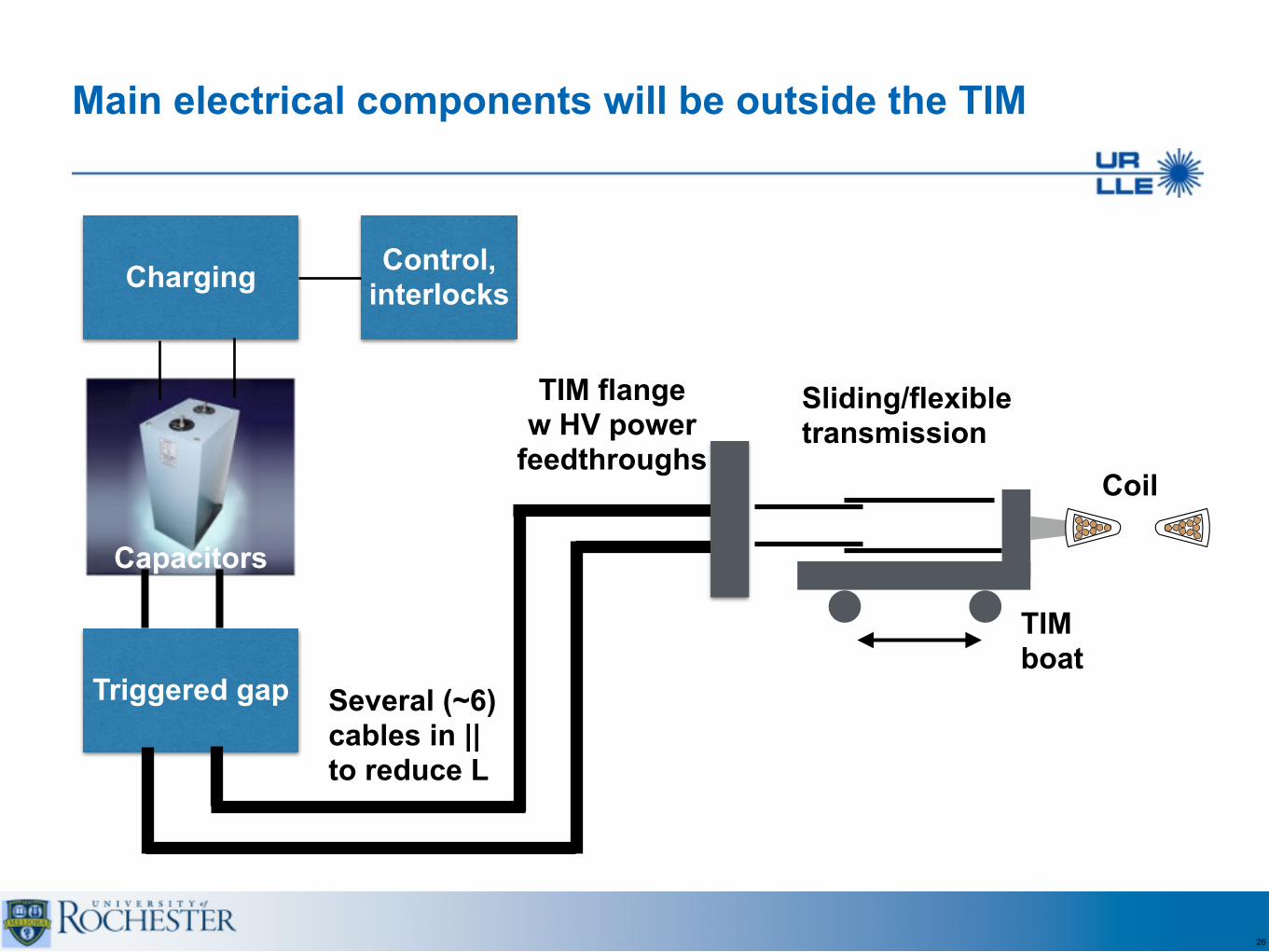
Main electrical components will be outside the TIM
26
Charging Control, interlocks
Triggered gap Several (~6) cables in || to reduce L
TIM flange w HV power
feedthroughs
TIM boat
Sliding/flexible transmission
Coil
Capacitors

MIFEDS upgrade will be staged
27
Stored Energy
Current/ Time to peak Bfield B
Energy Comments
MIFEDS 10T now
200 J 30kA/0.5µs 10 T 100 J TIM, single pulse use
MIFEDS 30 T 1 year
10 kJ 50kA/10µs 30 T 2 kJPower supply outside the TIM, multi-pulse
MIFEDS 50T 2 years
25 kJ 70ka/20µs 50 T 5 kJPower supply outside the TIM, single-pulse
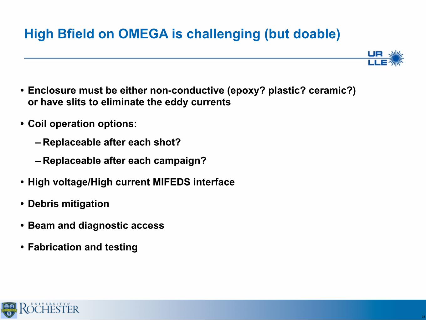
• Enclosure must be either non-conductive (epoxy? plastic? ceramic?) or have slits to eliminate the eddy currents
• Coil operation options:
– Replaceable after each shot?
– Replaceable after each campaign?
• High voltage/High current MIFEDS interface
• Debris mitigation
• Beam and diagnostic access
• Fabrication and testing
28
High Bfield on OMEGA is challenging (but doable)
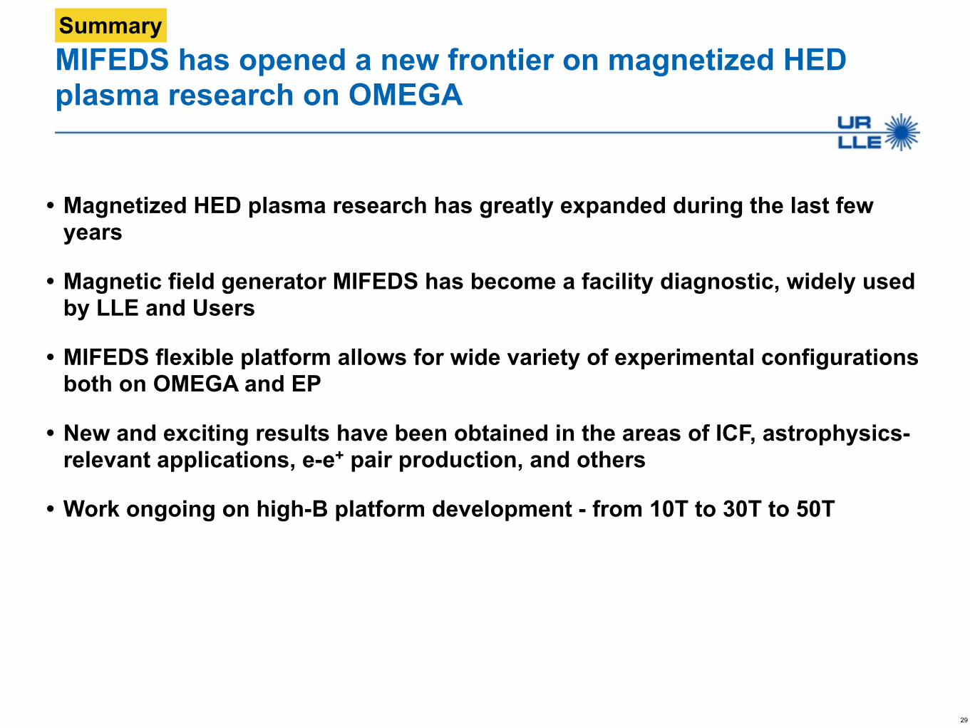
MIFEDS has opened a new frontier on magnetized HED plasma research on OMEGA
• Magnetized HED plasma research has greatly expanded during the last few years
• Magnetic field generator MIFEDS has become a facility diagnostic, widely used by LLE and Users
• MIFEDS flexible platform allows for wide variety of experimental configurations both on OMEGA and EP
• New and exciting results have been obtained in the areas of ICF, astrophysics-relevant applications, e-e+ pair production, and others
• Work ongoing on high-B platform development - from 10T to 30T to 50T
29
Summary
LLNL-PRES-XXXXXX This work was performed under the auspices of the U.S. Department of Energy by Lawrence Livermore National Laboratory under Contract DE-AC52-07NA27344. Lawrence Livermore National Security, LLC
B-field target deployment on NIF Facility Considerations B-Field Working Group
LLNL, Oct 12-13 2015
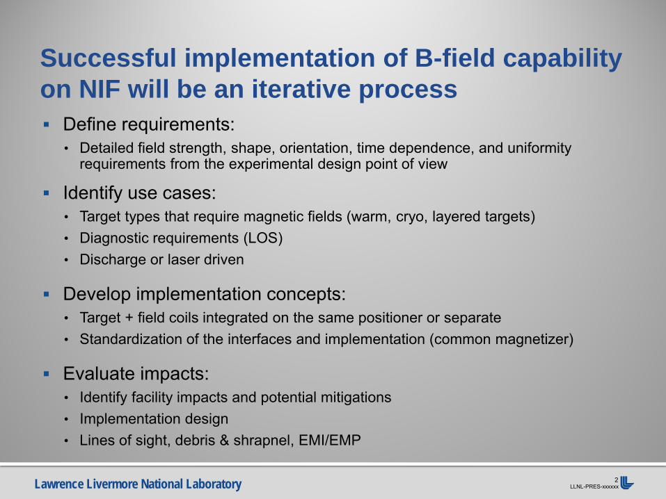
Lawrence Livermore National Laboratory LLNL-PRES-xxxxxx 2
Define requirements: • Detailed field strength, shape, orientation, time dependence, and uniformity
requirements from the experimental design point of view
Identify use cases: • Target types that require magnetic fields (warm, cryo, layered targets) • Diagnostic requirements (LOS) • Discharge or laser driven
Develop implementation concepts: • Target + field coils integrated on the same positioner or separate • Standardization of the interfaces and implementation (common magnetizer)
Evaluate impacts: • Identify facility impacts and potential mitigations • Implementation design • Lines of sight, debris & shrapnel, EMI/EMP
Successful implementation of B-field capability on NIF will be an iterative process
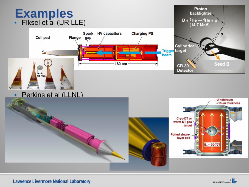
Lawrence Livermore National Laboratory LLNL-PRES-xxxxxx 3
Fiksel et al (UR LLE)
Perkins et al (LLNL)
Examples
Lawrence Livermore National Laboratory LLNL-PRES-xxxxxx 4
Facility considerations Clearances • Clear 3w beams
• Maintain driver beam stayout zones
• Clear or manage unconverted light beams • Maintain unconverted light stayout zone or implement
laser shielding in impacted area
• Clear required diagnostic lines of sight • Keep lines of sight open for the required diagnostic(s)
• Fit within the TAS jaws (max width and height)
• Alignable
Lawrence Livermore National Laboratory LLNL-PRES-xxxxxx 5
Facility considerations Impacts • Reduce additional debris and shrapnel to protect optics
and diagnostics • Minimize coil mass (~0.5 mg), material selection
• Testing and characterization recommended to determine debris distribution
• Prefer designs that vaporize the coil and reduce debris • Conduct standard debris and shrapnel analysis,
(directionality, vaporized mass, materials, energy …)
• Minimize EMI/EMP effects on TD and other equipment • Ensure the EMI/EMP created by the magnetic field
generator and coil do not perturb the diagnostics/equipment used for the experiment in a way it affects the experimental outcome or system operation
Lawrence Livermore National Laboratory LLNL-PRES-xxxxxx 6
Facility considerations Target capabilities • Thermal control for CRYO targets
• Warm or cold, temperature and accuracy (Layered?) • For cryo targets, are shrouds required? This will need
a dedicated design effort
• Max gas release in the TC (shot time, failure) • The amount of gas vented into the TC during a shot
shall be less than 200 standard CC
• Provide target gas fill management capability • What gas(ses) are needed, what pressure(s), what fill
pressure tolerance • Tritium use drives the positioner used

Lawrence Livermore National Laboratory LLNL-PRES-xxxxxx 7
Concept of CRYO Target magnetized through inductive coupling powered by DIM (Rhodes, Perkins et al, LLNL)
DIM 90-315
C-TARPOS Target w/hohlraum coil
Inductive coupler
DIM T-line
Target T-line
Inductive coupler separated
Target may be aligned as usual with TARPOS. Then, DIM is inserted for a no-contact power coupling. Target is not disturbed.
Lawrence Livermore National Laboratory LLNL-PRES-xxxxxx 8
Facility considerations Magnetizer implementation
• Magnetizer design compatible with positioner design and cables
• Evaluate magnetizer pulsed power cables (what are limits)
• Switch/trigger requirements (optical vs electrical) • TANDM provides dual flexible cable tray usage • Implementation on (CRYO)TARPOS is challenging
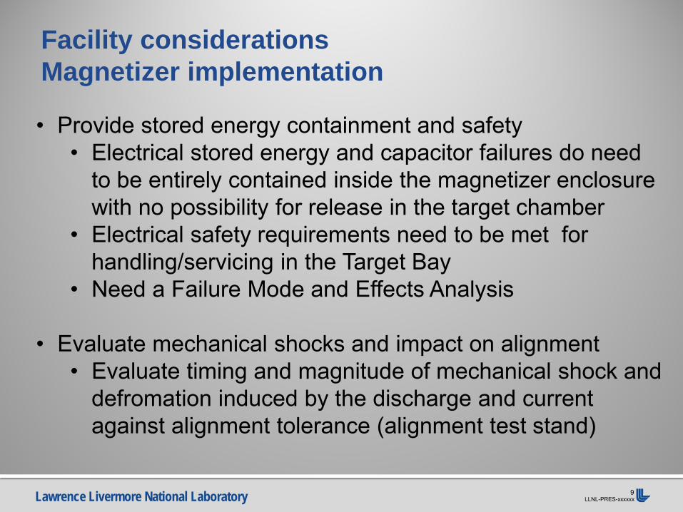
Lawrence Livermore National Laboratory LLNL-PRES-xxxxxx 9
Facility considerations Magnetizer implementation
• Provide stored energy containment and safety • Electrical stored energy and capacitor failures do need
to be entirely contained inside the magnetizer enclosure with no possibility for release in the target chamber
• Electrical safety requirements need to be met for handling/servicing in the Target Bay
• Need a Failure Mode and Effects Analysis
• Evaluate mechanical shocks and impact on alignment • Evaluate timing and magnitude of mechanical shock and
defromation induced by the discharge and current against alignment tolerance (alignment test stand)
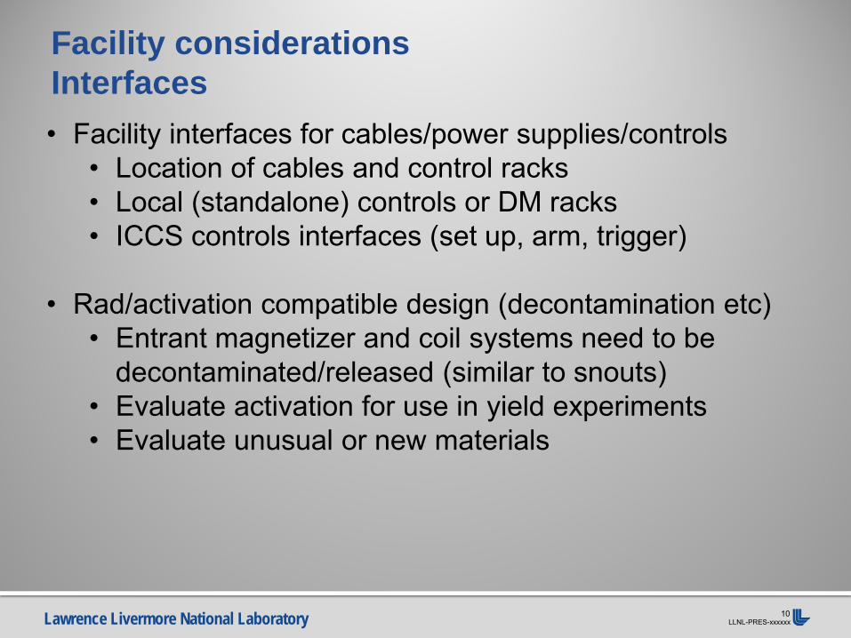
Lawrence Livermore National Laboratory LLNL-PRES-xxxxxx 10
Facility considerations Interfaces • Facility interfaces for cables/power supplies/controls
• Location of cables and control racks • Local (standalone) controls or DM racks • ICCS controls interfaces (set up, arm, trigger)
• Rad/activation compatible design (decontamination etc)
• Entrant magnetizer and coil systems need to be decontaminated/released (similar to snouts)
• Evaluate activation for use in yield experiments • Evaluate unusual or new materials

Lawrence Livermore National Laboratory LLNL-PRES-xxxxxx 11
Facility considerations Trade-offs • Flexibility/commonality of magnetic field generator for
different targets would be highly advantageous • Cost effective • Efficient implementation and operation • Use coil LRU to achieve specific field parameters
• Establish requirements for offline and online
characterization and calibration • Field strength, uniformity and gradients • Spatial extent and shape • Temporal profile • Field evaluation during shot and disintegration
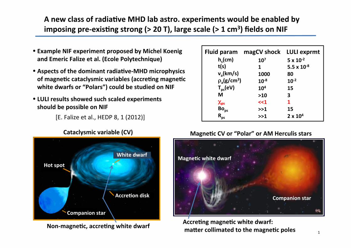
1
B_reqmts_tkoenig_falize_V2_bar2.pptx;1
A new class of radia/ve MHD lab astro. experiments would be enabled by imposing pre-‐exis/ng strong (> 20 T), large scale (> 1 cm3) fields on NIF
Cataclysmic variable (CV) Magne/c CV or “Polar” or AM Herculis stars
Accre/ng magne/c white dwarf: maRer collimated to the magne/c poles Non-‐magne/c, accre/ng white dwarf
[E. Falize et al., HEDP 8, 1 (2012)]
Fluid param magCV shock LULI exprmt hs(cm) t(s) va(km/s) ρa(g/cm3) Tps(eV) M χps Bops Rps
107 1 1000 10-‐8 104 >10 <<1 >>1 >>1
5 x 10-‐2 5.5 x 10-‐8 80 10-‐2 15 3 1 15 2 x 10⁴
Example NIF experiment proposed by Michel Koenig and Emeric Falize et al. (Ecole Polytechnique)
Aspects of the dominant radia/ve-‐MHD microphysics of magne/c cataclysmic variables (accre/ng magne/c white dwarfs or “Polars”) could be studied on NIF
LULI results showed such scaled experiments should be possible on NIF
Hot spot
White dwarf
Accre/on disk
Companion star
Magne/c white dwarf
Companion star
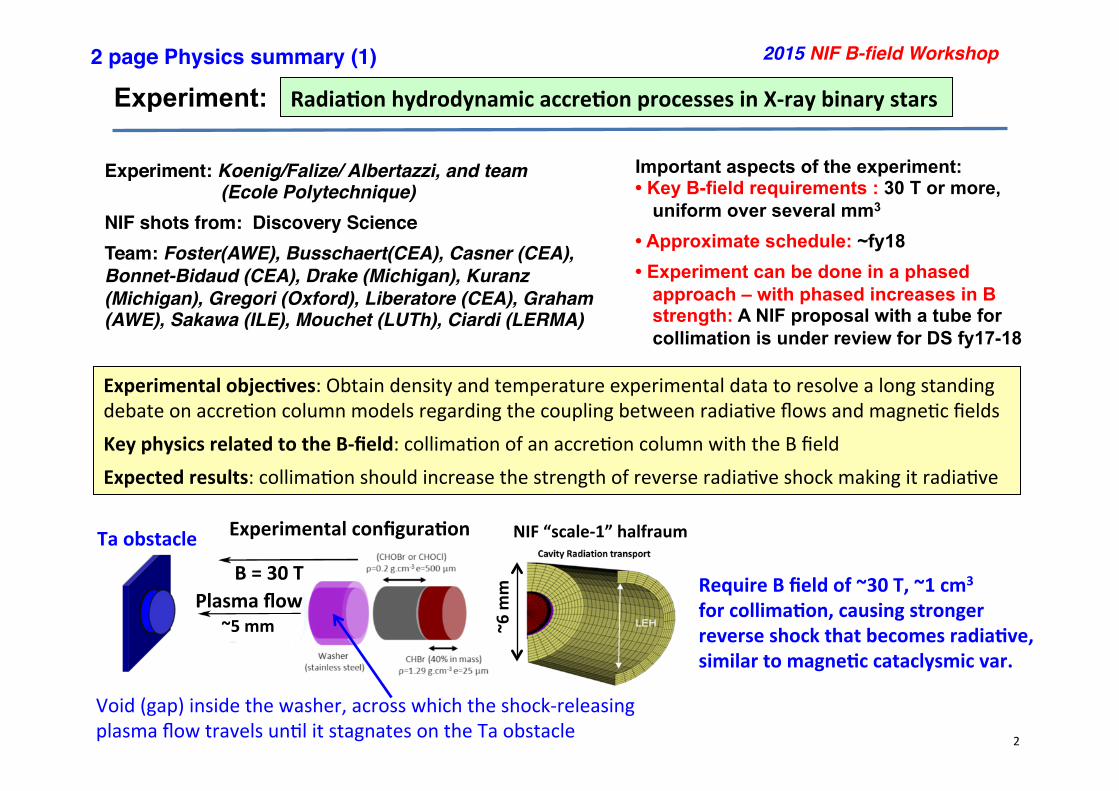
2
B_reqmts_tkoenig_falize_V2_bar2.pptx;2
Experiment:
10/11/15 2015 NIF B-‐field Workshop
Radia/on hydrodynamic accre/on processes in X-‐ray binary stars
2015 NIF B-field Workshop!
Experiment: Koenig/Falize/ Albertazzi, and team!! ! (Ecole Polytechnique)!
!
NIF shots from: Discovery Science!!
Team: Foster(AWE), Busschaert(CEA), Casner (CEA), Bonnet-Bidaud (CEA), Drake (Michigan), Kuranz (Michigan), Gregori (Oxford), Liberatore (CEA), Graham (AWE), Sakawa (ILE), Mouchet (LUTh), Ciardi (LERMA)!
Important aspects of the experiment: • Key B-field requirements : 30 T or more,
uniform over several mm3
• Approximate schedule: ~fy18
• Experiment can be done in a phased approach – with phased increases in B strength: A NIF proposal with a tube for collimation is under review for DS fy17-18
Experimental objec/ves: Obtain density and temperature experimental data to resolve a long standing debate on accrePon column models regarding the coupling between radiaPve flows and magnePc fields
Key physics related to the B-‐field: collimaPon of an accrePon column with the B field
Expected results: collimaPon should increase the strength of reverse radiaPve shock making it radiaPve
2 page Physics summary (1)!
Experimental configura/on
Require B field of ~30 T, ~1 cm3 for collima/on, causing stronger reverse shock that becomes radia/ve, similar to magne/c cataclysmic var.
Ta obstacle
Void (gap) inside the washer, across which the shock-‐releasing plasma flow travels unPl it stagnates on the Ta obstacle
B = 30 T Plasma flow
NIF “scale-‐1” halfraum ~6 m
m
~5 mm
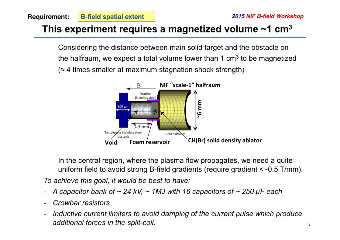
3
B_reqmts_tkoenig_falize_V2_bar2.pptx;3
This experiment requires a magnetized volume ~1 cm3 B-field spatial extent!Requirement:!
Considering the distance between main solid target and the obstacle on the halfraum, we expect a total volume lower than 1 cm3 to be magnetized (≈ 4 times smaller at maximum stagnation shock strength)
In the central region, where the plasma flow propagates, we need a quite uniform field to avoid strong B-field gradients (require gradient <~0.5 T/mm).
To achieve this goal, it would be best to have: - A capacitor bank of ~ 24 kV, ~ 1MJ with 16 capacitors of ~ 250 µF each - Crowbar resistors - Inductive current limiters to avoid damping of the current pulse which produce
additional forces in the split-coil.
2015 NIF B-field Workshop!
Void Foam reservoir CH(Br) solid density ablator
NIF “scale-‐1” halfraum
~6 m
m

4
B_reqmts_tkoenig_falize_V2_bar2.pptx;4
This experiment requires a B≥ 20 T and uniformity to 10%
10/11/15 2015 NIF B-‐field Workshop
B-field magnitude!Requirement:!
B-field magnitude : - the B field must be over 20 up to 40 T (more if possible) B-field spatial variation requirements - The B field must be uniform on about 1 cm3 with a gradient ≈ 0.5 T/mm at maximum. B-field spatial uniformity requirements We should have a small B-field gradient in the center of the coil of the order of 0.5 T/mm in longitudinal and radial direction.
2015 NIF B-field Workshop!
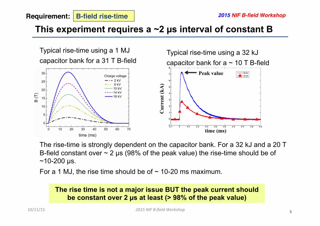
5
B_reqmts_tkoenig_falize_V2_bar2.pptx;5
This experiment requires a ~2 µs interval of constant B
10/11/15 2015 NIF B-‐field Workshop
B-field rise-time!Requirement:! 2015 NIF B-field Workshop!
Typical rise-time using a 1 MJ capacitor bank for a 31 T B-field The rise-time is strongly dependent on the capacitor bank. For a 32 kJ and a 20 T B-field constant over ~ 2 µs (98% of the peak value) the rise-time should be of ~10-200 µs. For a 1 MJ, the rise time should be of ~ 10-20 ms maximum.
Cur
rent
(kA
)
time (ms)
Peak value
The rise time is not a major issue BUT the peak current should be constant over 2 µs at least (> 98% of the peak value)
Typical rise-time using a 32 kJ capacitor bank for a ~ 10 T B-field
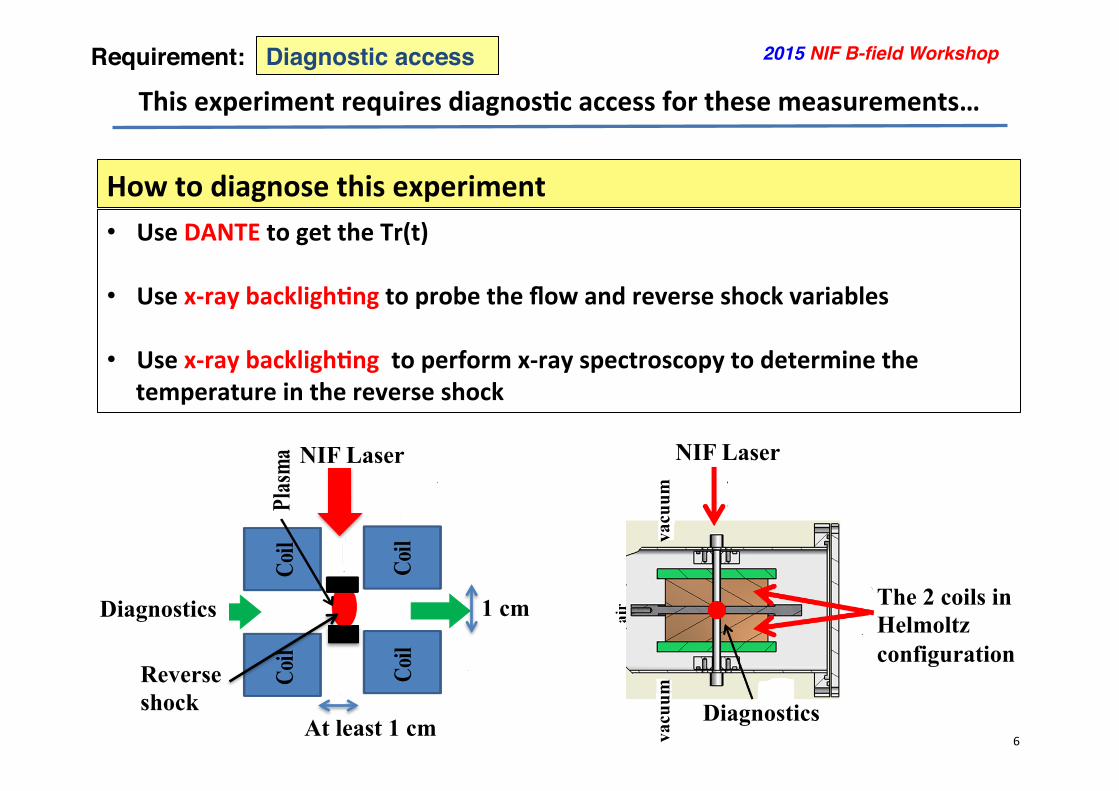
6
B_reqmts_tkoenig_falize_V2_bar2.pptx;6
This experiment requires diagnos/c access for these measurements…
Diagnostic access!Requirement:! 2015 NIF B-field Workshop!
How to diagnose this experiment • Use DANTE to get the Tr(t)
• Use x-‐ray backligh/ng to probe the flow and reverse shock variables
• Use x-‐ray backligh/ng to perform x-‐ray spectroscopy to determine the temperature in the reverse shock
NIF Laser
Diagnostics
Reverse shock
At least 1 cm
1 cm
NIF Laser
Diagnostics
The 2 coils in Helmoltz configuration
vacu
um
vacu
um

7
B_reqmts_tkoenig_falize_V2_bar2.pptx;7
Experiment: Radia/on hydrodynamic accre/on processes in X-‐ray binary stars
2 page Physics summary (2)!
This experiment is following the proposal P-‐000050 POLAR experiment (PI: Falize) • The radiation transport platform (RTp) will be used to drive a strong shock through a
low density foam to generate a high velocity supersonic plasma flow on release that will impact and stagnate on a solid obstacle mimicking a white dwarf atmosphere
• The RTp will produce a sufficiently long x-ray pulse to drive the large material mass contained in a reservoir, producing high flow velocities: conditions similar to astrophysical conditions can be achieved!
• The B-field must be parallel to the flow propagation in order to collimate it and prevent lateral decompression, strengthening the radiative stagnation shock.
2015 NIF B-field Workshop!
• The key diagnostics in this experiment will be the x-ray framing radiograph diagnostic with the 6x hGXD (2 strips) inserted in DIM (90,78). Two Dante are required to infer the raditiave temperature from the halfraums !
• As we remove in this experiment the original tube to collimate the plasma flow, access to emission from the flow or reverse shock will allow the use of x-ray spectrometry "
Reverse shock
obstacle Laser 2 mm
B = 10 T
LULI2000 Data
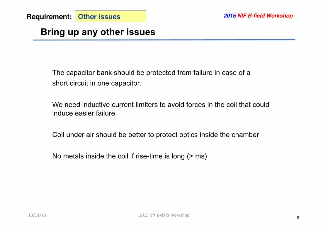
8
B_reqmts_tkoenig_falize_V2_bar2.pptx;8
Bring up any other issues
10/11/15 2015 NIF B-‐field Workshop
Other issues!Requirement:! 2015 NIF B-field Workshop!
The capacitor bank should be protected from failure in case of a short circuit in one capacitor. We need inductive current limiters to avoid forces in the coil that could induce easier failure. Coil under air should be better to protect optics inside the chamber No metals inside the coil if rise-time is long (> ms)
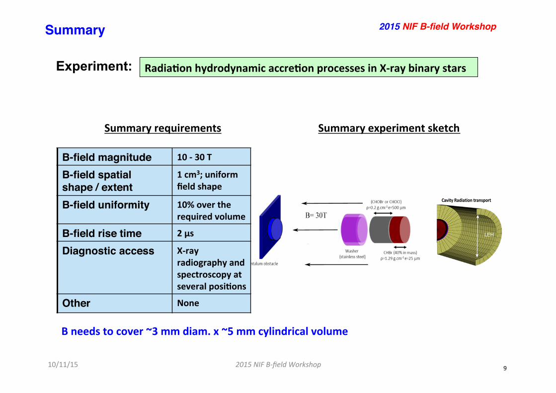
9
B_reqmts_tkoenig_falize_V2_bar2.pptx;9
Experiment:
10/11/15 2015 NIF B-‐field Workshop
Radia/on hydrodynamic accre/on processes in X-‐ray binary stars
Summary!
Summary experiment sketch Summary requirements
2015 NIF B-field Workshop!
B-field magnitude! 10 -‐ 30 T
B-field spatial shape / extent!
1 cm3; uniform field shape
B-field uniformity! 10% over the required volume
B-field rise time! 2 µs
Diagnostic access! X-‐ray radiography and spectroscopy at several posi/ons
Other! None
B needs to cover ~3 mm diam. x ~5 mm cylindrical volume
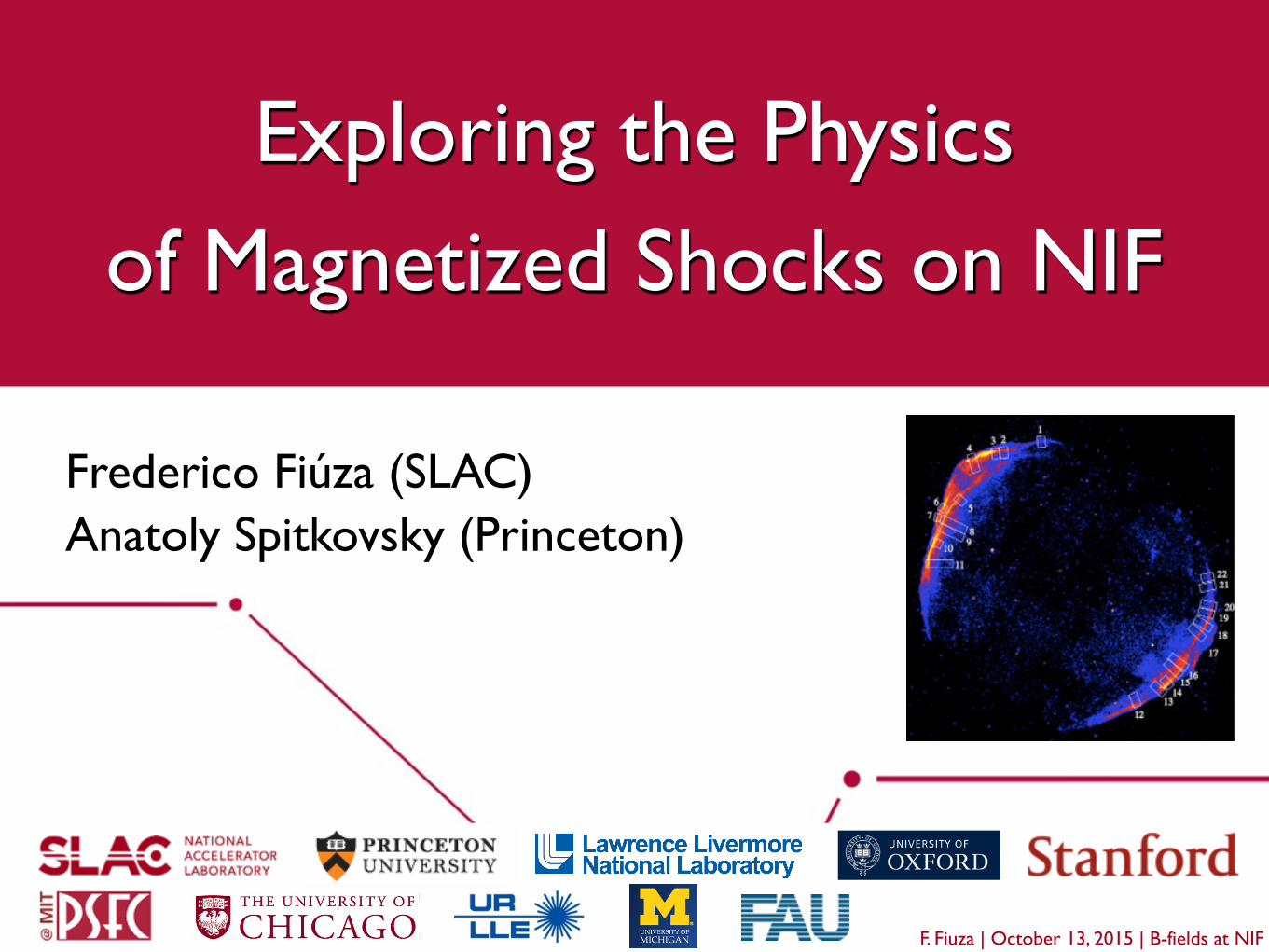
Exploring the Physics!of Magnetized Shocks on NIF
F. Fiuza | October 13, 2015 | B-fields at NIF
Frederico Fiúza (SLAC)!Anatoly Spitkovsky (Princeton)!!
!
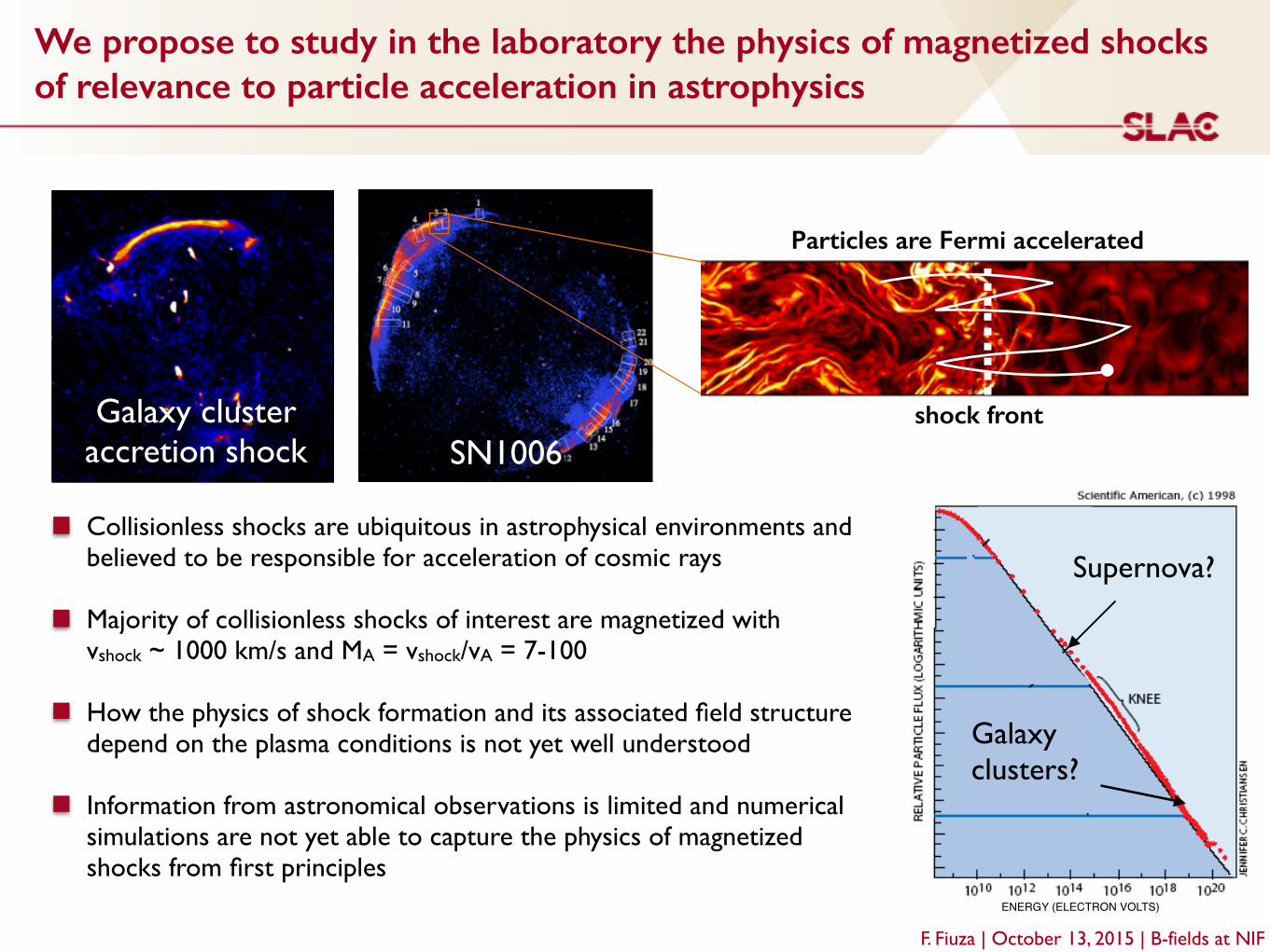
We propose to study in the laboratory the physics of magnetized shocks of relevance to particle acceleration in astrophysics
SN1006Galaxy cluster
accretion shock
ENERGY (ELECTRON VOLTS)
Galaxy! clusters?
Supernova?!Collisionless shocks are ubiquitous in astrophysical environments and believed to be responsible for acceleration of cosmic rays!!Majority of collisionless shocks of interest are magnetized with vshock ~ 1000 km/s and MA = vshock/vA = 7-100!!How the physics of shock formation and its associated field structure depend on the plasma conditions is not yet well understood!!Information from astronomical observations is limited and numerical simulations are not yet able to capture the physics of magnetized shocks from first principles
shock front
Particles are Fermi accelerated
F. Fiuza | October 13, 2015 | B-fields at NIF
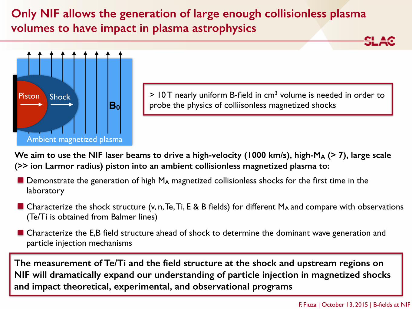
Only NIF allows the generation of large enough collisionless plasma volumes to have impact in plasma astrophysics
F. Fiuza | October 13, 2015 | B-fields at NIF
We aim to use the NIF laser beams to drive a high-velocity (1000 km/s), high-MA (> 7), large scale (>> ion Larmor radius) piston into an ambient collisionless magnetized plasma to:
Demonstrate the generation of high MA magnetized collisionless shocks for the first time in the laboratory!
Characterize the shock structure (v, n, Te, Ti, E & B fields) for different MA and compare with observations (Te/Ti is obtained from Balmer lines)!
Characterize the E,B field structure ahead of shock to determine the dominant wave generation and particle injection mechanisms!
The measurement of Te/Ti and the field structure at the shock and upstream regions on NIF will dramatically expand our understanding of particle injection in magnetized shocks and impact theoretical, experimental, and observational programs
Shock
Ambient magnetized plasma
PistonB0
> 10 T nearly uniform B-field in cm3 volume is needed in order to probe the physics of colliisonless magnetized shocks
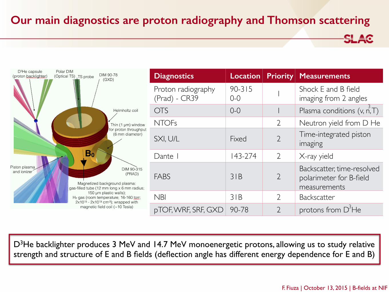
Our main diagnostics are proton radiography and Thomson scattering
F. Fiuza | October 13, 2015 | B-fields at NIF
D3He backlighter produces 3 MeV and 14.7 MeV monoenergetic protons, allowing us to study relative strength and structure of E and B fields (deflection angle has different energy dependence for E and B)
Diagnostics Location Priority Measurements
Proton radiography (Prad) - CR39
90-315!0-0 1 Shock E and B field
imaging from 2 anglesOTS 0-0 1 Plasma conditions (v, n, T)NTOFs 2 Neutron yield from D He
SXI, U/L Fixed 2 Time-integrated piston imaging
Dante 1 143-274 2 X-ray yield
FABS 31B 2Backscatter, time-resolved polarimeter for B-field measurements
NBI 31B 2 BackscatterpTOF, WRF, SRF, GXD 90-78 2 protons from D He
3
3
B0

We need > 10 T Helmholtz B-field in cm3 volume
3"turns"each"side,"40"kA"
3"mm"6"mm"
16"m
m" 12"m
m"
z"(mm)"
Bz"(T
)"
B-field capability is currently being designed for a maximum current of 80 kA, but 40 kA would be enough for our experiments, producing 12 Tesla (or ~ 10 T cm3)!
F. Fiuza | October 13, 2015 | B-fields at NIFcourtesy of J. Perkins and M. Rhodes
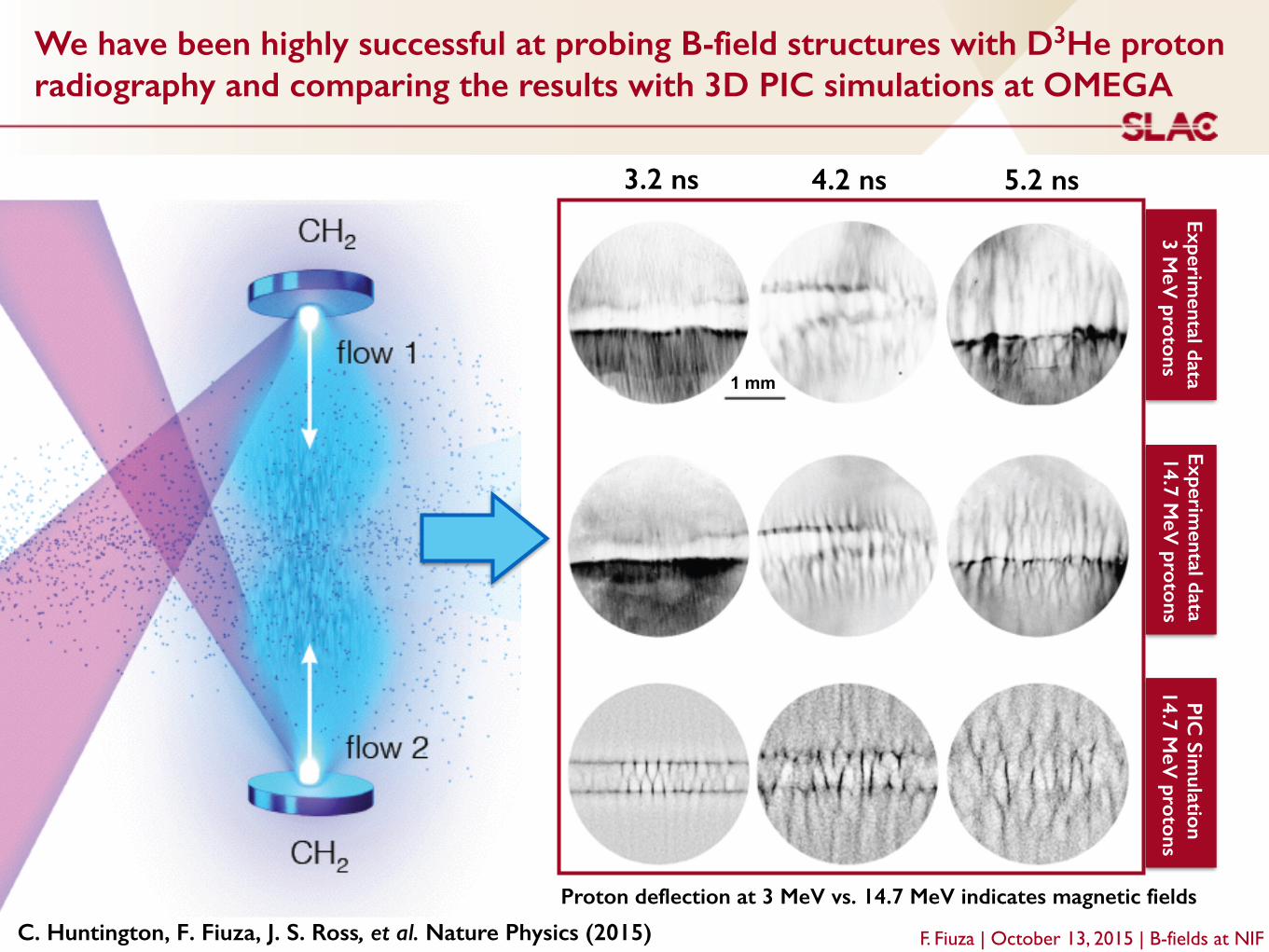
We have been highly successful at probing B-field structures with D3He proton radiography and comparing the results with 3D PIC simulations at OMEGA
1 mm
3.2 ns 4.2 ns 5.2 ns
Experimental data
3 MeV
protonsExperim
ental data 14.7 M
eV protons
PIC Sim
ulation 14.7 M
eV protons
Proton deflection at 3 MeV vs. 14.7 MeV indicates magnetic fields
C. Huntington, F. Fiuza, J. S. Ross, et al. Nature Physics (2015) F. Fiuza | October 13, 2015 | B-fields at NIF
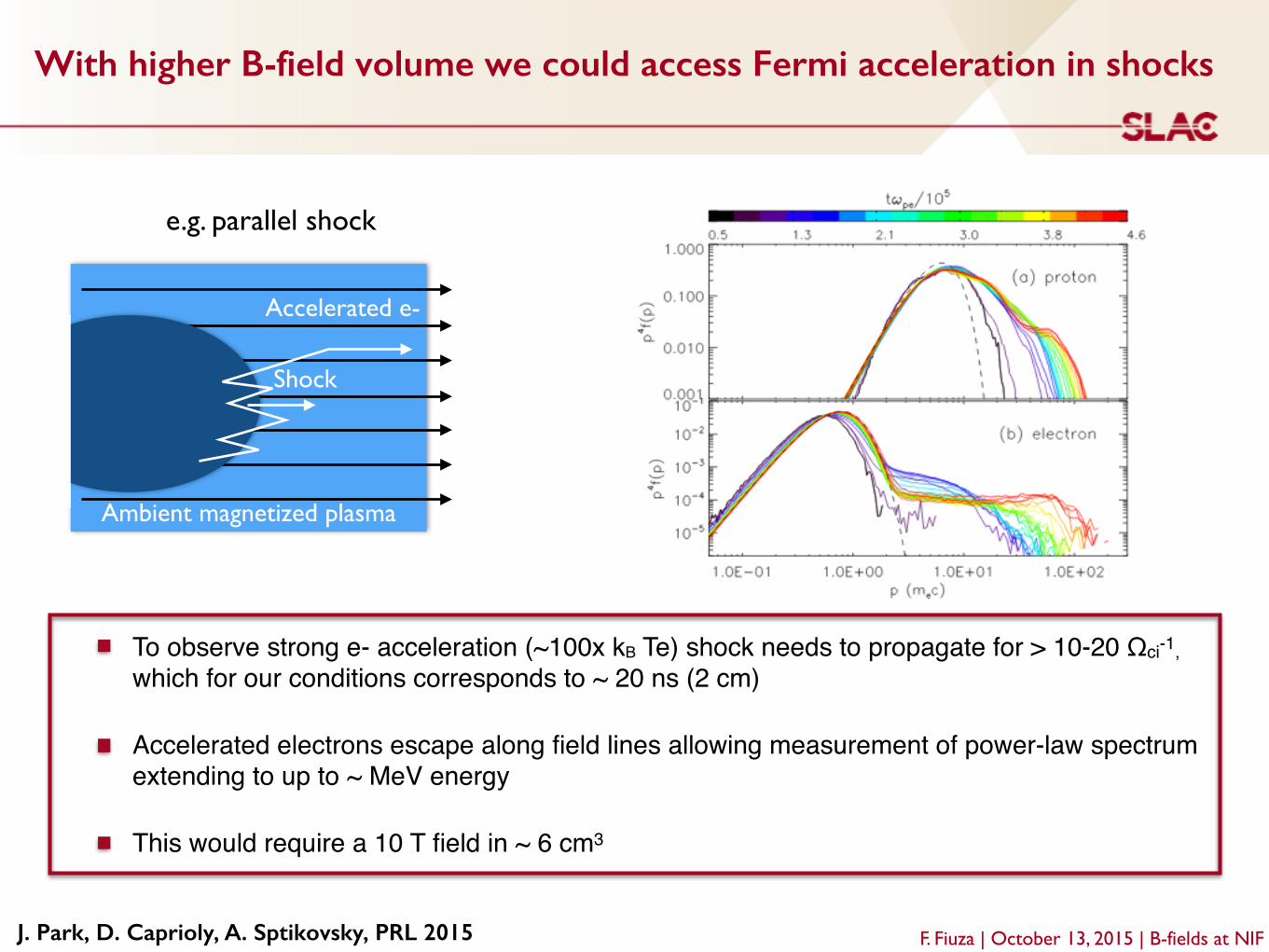
With higher B-field volume we could access Fermi acceleration in shocks
F. Fiuza | October 13, 2015 | B-fields at NIFJ. Park, D. Caprioly, A. Sptikovsky, PRL 2015
Shock
Ambient magnetized plasma
e.g. parallel shock
Accelerated e-
To observe strong e- acceleration (~100x kB Te) shock needs to propagate for > 10-20 Ωci-1, which for our conditions corresponds to ~ 20 ns (2 cm)!
Accelerated electrons escape along field lines allowing measurement of power-law spectrum extending to up to ~ MeV energy!
This would require a 10 T field in ~ 6 cm3
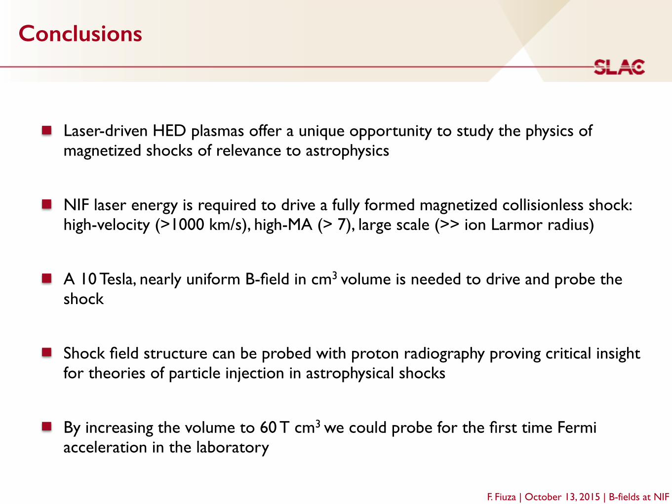
Conclusions
F. Fiuza | October 13, 2015 | B-fields at NIF
Laser-driven HED plasmas offer a unique opportunity to study the physics of magnetized shocks of relevance to astrophysics!
NIF laser energy is required to drive a fully formed magnetized collisionless shock: high-velocity (>1000 km/s), high-MA (> 7), large scale (>> ion Larmor radius) !
A 10 Tesla, nearly uniform B-field in cm3 volume is needed to drive and probe the shock!
Shock field structure can be probed with proton radiography proving critical insight for theories of particle injection in astrophysical shocks!
By increasing the volume to 60 T cm3 we could probe for the first time Fermi acceleration in the laboratory!
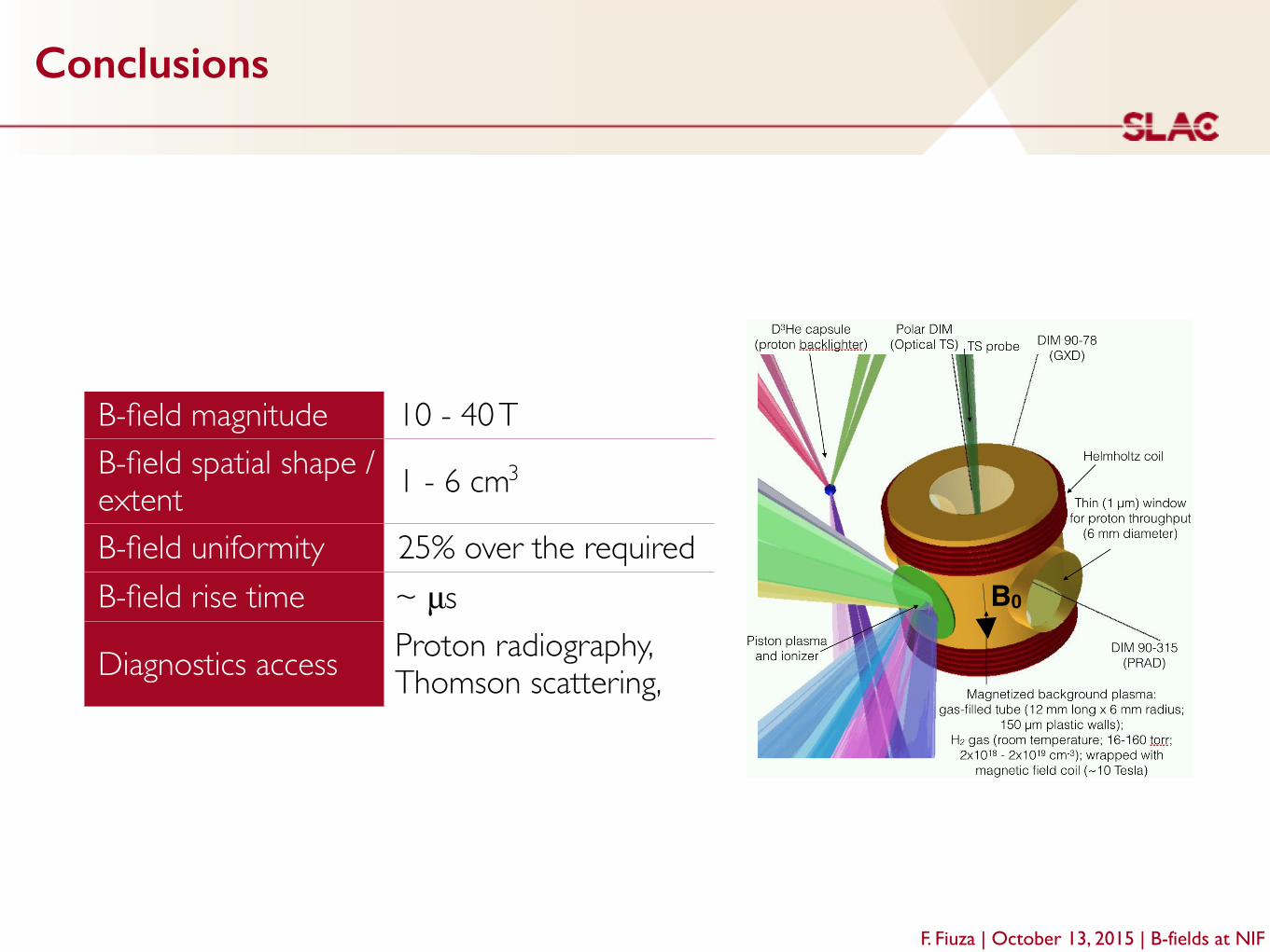
Conclusions
F. Fiuza | October 13, 2015 | B-fields at NIF
B-field magnitude 10 - 40 TB-field spatial shape / extent 1 - 6 cm
B-field uniformity 25% over the required volumeB-field rise time ~ μs
Diagnostics access Proton radiography, Thomson scattering, spectroscopy
B0
3
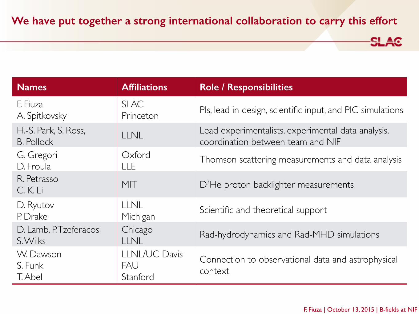
We have put together a strong international collaboration to carry this effort
Names Affiliations Role / Responsibilities
F. Fiuza!A. Spitkovsky
SLAC!Princeton PIs, lead in design, scientific input, and PIC simulations
H.-S. Park, S. Ross, B. Pollock LLNL Lead experimentalists, experimental data analysis,
coordination between team and NIFG. Gregori!D. Froula
Oxford!LLE
Thomson scattering measurements and data analysis
R. Petrasso!C. K. Li MIT D He proton backlighter measurements
D. Ryutov!P. Drake
LLNL!Michigan Scientific and theoretical support
D. Lamb, P. Tzeferacos!S. Wilks
Chicago!LLNL Rad-hydrodynamics and Rad-MHD simulations
W. Dawson!S. Funk!T. Abel
LLNL/UC Davis!FAU!Stanford
Connection to observational data and astrophysical context
3
F. Fiuza | October 13, 2015 | B-fields at NIF

Experiment:
10/23/2015 2015 NIF B-field Workshop 1
Fermi acceleration at shocks
2015 NIF B-field Workshop
Experiment: Fermi acceleration Responsible Org: TBD NIF shots from: DS Shot RI: H. –S. Park / G. Gregori Engineer: TBD
Important aspects of the experiment: • Need 0.5 T over >1,200 cm3 volume (12
cm dia x 12 cm long tube)
Experimental objectives: Demonstrate that 1st order Fermi acceleration can occur in converging flows. First experimental verification of a process believed to occur at supernova remnant shocks. Key physics related to having a B-field: Plasma needs to be pre-magnetized. Shocks expanding in magnetized plasma. Expected results: Measure electron spectrum and proton spectrum
2 page Physics summary (1)
Summary experiment sketch
Helmholtz coil
Helmholtz coil
B=0.5 T
Expanding shock
Gas cell or foam
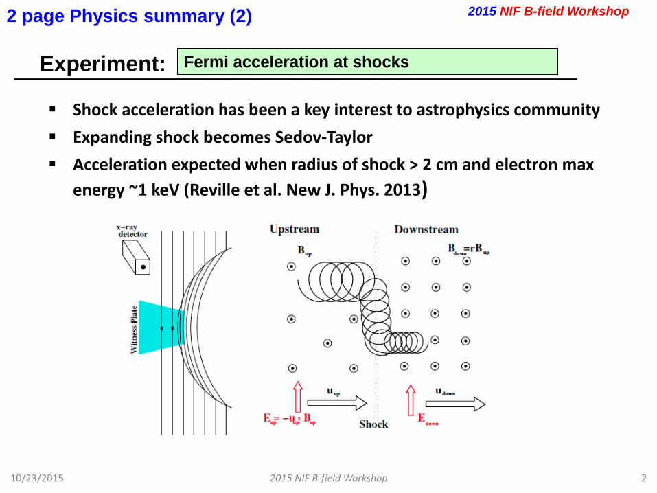
Experiment:
10/23/2015 2015 NIF B-field Workshop 2
Fermi acceleration at shocks
2 page Physics summary (2) 2015 NIF B-field Workshop
Shock acceleration has been a key interest to astrophysics community Expanding shock becomes Sedov-Taylor Acceleration expected when radius of shock > 2 cm and electron max
energy ~1 keV (Reville et al. New J. Phys. 2013)

Experiment:
10/23/2015 2015 NIF B-field Workshop 3
Fermi acceleration at shocks
2 page Physics summary (2)
More detailed experimental sketch showing: • Large gas cell: 12 cm diameter, 12 cm long • Hydrogen gas fill (ne~1016 cm-3), alternatively, foam filled plastic
hohlraum would work • CD capsule placed in the center of the gas cell
2015 NIF B-field Workshop
Helmholtz coil
Helmholtz coil
B=0.5 T
• NIF beams (400 kJ) used to illuminate capsule and drive shock in the ambient gas/foam
• Expanding shock becomes Sedov-Taylor
• Acceleration expected when radius of shock > 2 cm and electron max energy ~1 keV (Reville et al. New J. Phys. 2013)
Expanding shock
Gas cell or foam
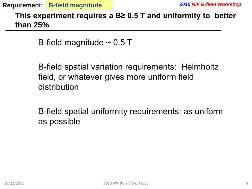
This experiment requires a B≥ 0.5 T and uniformity to better than 25%
10/23/2015 2015 NIF B-field Workshop 4
B-field magnitude Requirement:
B-field magnitude ~ 0.5 T B-field spatial variation requirements: Helmholtz field, or whatever gives more uniform field distribution B-field spatial uniformity requirements: as uniform as possible
2015 NIF B-field Workshop
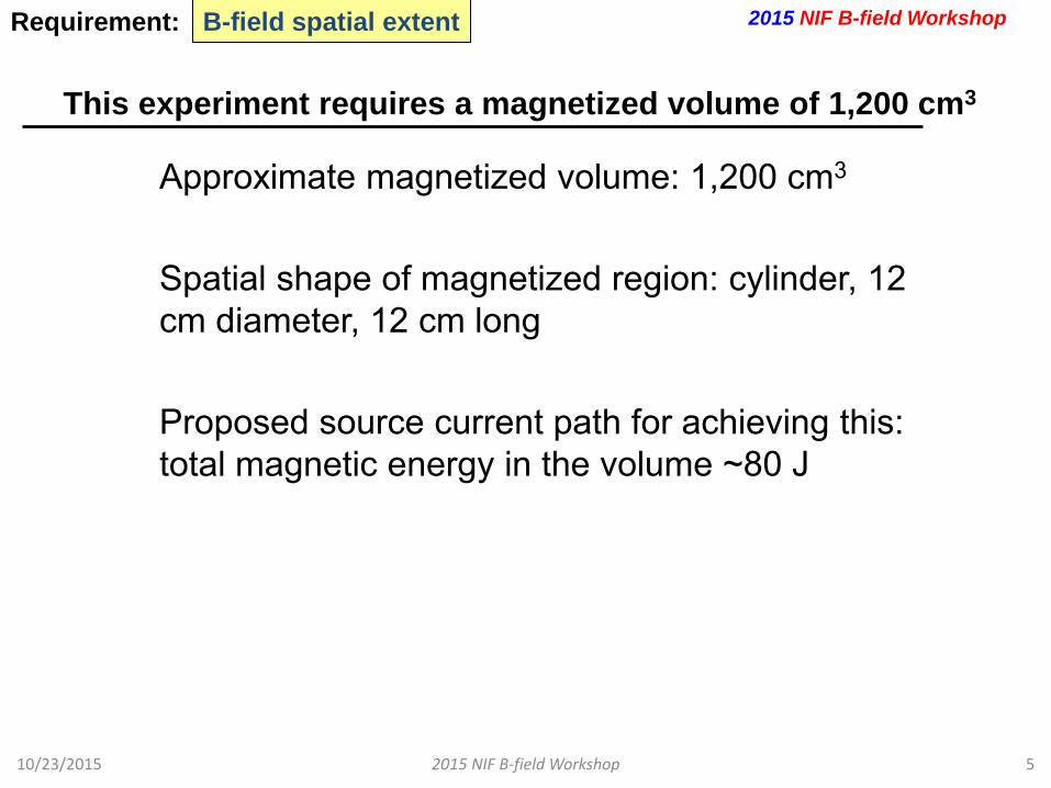
This experiment requires a magnetized volume of 1,200 cm3
10/23/2015 2015 NIF B-field Workshop 5
B-field spatial extent Requirement:
Approximate magnetized volume: 1,200 cm3
Spatial shape of magnetized region: cylinder, 12 cm diameter, 12 cm long Proposed source current path for achieving this: total magnetic energy in the volume ~80 J
2015 NIF B-field Workshop

This experiment requires the field to turn on no faster than 2 µs
10/23/2015 2015 NIF B-field Workshop 6
B-field rise-time Requirement:
No special rise time requirements
2015 NIF B-field Workshop
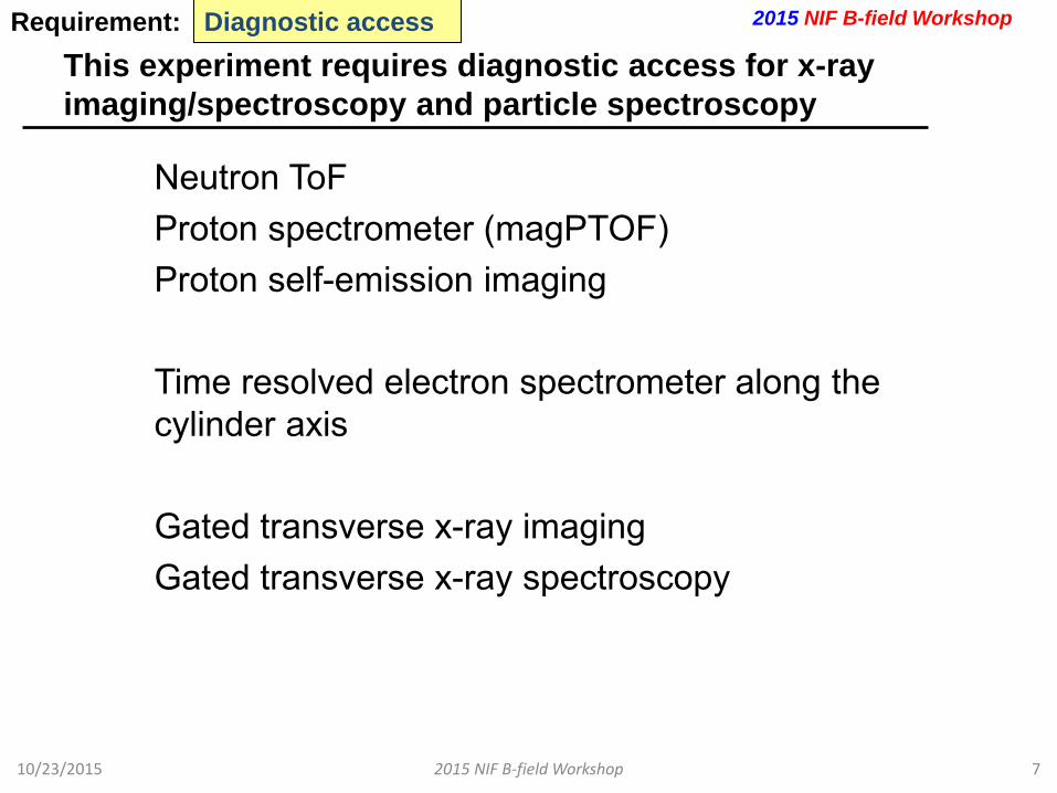
This experiment requires diagnostic access for x-ray imaging/spectroscopy and particle spectroscopy
10/23/2015 2015 NIF B-field Workshop 7
Diagnostic access Requirement:
Neutron ToF Proton spectrometer (magPTOF) Proton self-emission imaging Time resolved electron spectrometer along the cylinder axis Gated transverse x-ray imaging Gated transverse x-ray spectroscopy
2015 NIF B-field Workshop

Bring up any other issues
10/23/2015 2015 NIF B-field Workshop 8
Other issues Requirement:
One slide: Machine safety considerations (debris, laser damage, backscatter, diagnostic damage risk, etc) Feel free to share insights on working out solutions to any of these issues - Debris mitigation of large volume detector (albeit low mass) - Construction and debris mitigation of a large volume B-field coil - Proper backscatter calculation or PQ experiment for gas or
foam field hohlraums
2015 NIF B-field Workshop
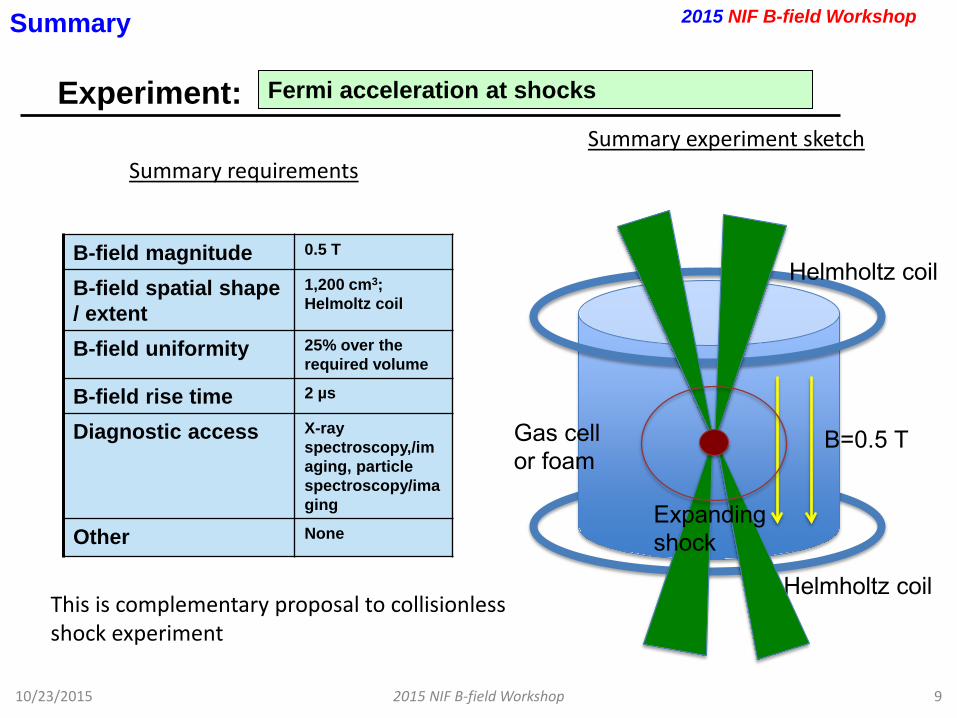
Experiment:
10/23/2015 2015 NIF B-field Workshop 9
Fermi acceleration at shocks
Summary
Summary experiment sketch
B-field magnitude 0.5 T
B-field spatial shape / extent
1,200 cm3; Helmoltz coil
B-field uniformity 25% over the required volume
B-field rise time 2 µs
Diagnostic access X-ray spectroscopy,/imaging, particle spectroscopy/imaging
Other None
Summary requirements
2015 NIF B-field Workshop
Gas cell or foam
Helmholtz coil
Helmholtz coil
B=0.5 T
Expanding shock
This is complementary proposal to collisionless shock experiment
Shinsuke Fujioka* *Institute of Laser Engineering, Osaka University, Japan Japan-US Symposium on Giant Laser Physics 1

Generation of kilo-tesla B-field Kilo-Tesla B-field is generated with the laser-driven capacitor-coil scheme. Strength (600 – 700 T) of B-field is characterized by using a B-dot probe and
proton defractmetory.
Strong-B field science Hydrodynamics and thermal transport with 0.1 kT. B-assisted central ignition and fast ignition with 1 kT. Atomic physics with >10 kT. High energy astrophysics with >100 kT.
Plasma hydrodynamics under strong magnetic field
A thin plastic foil is accelerated by laser beams under strong magnetic field. Flying velocity of the laser-driven plastic foil is 50% faster in the magnetic field
compared to that in normal conditions. Growth of hydrodynamic instability may be accelerated in the strong magnetic
field.
Thermal transport under strong magnetic field Anisotropic thermal conduction plays important roles in the magnetized
plasma. Anisotropic thermal conduction can be studied more directly by using a low-
density foam target.
SUMMARY
2
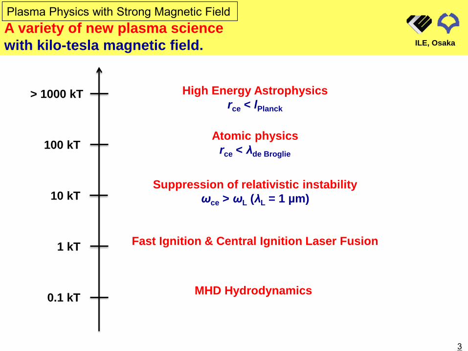
A variety of new plasma science with kilo-tesla magnetic field.
Plasma Physics with Strong Magnetic Field
ILE, Osaka
High Energy Astrophysics rce < lPlanck
Fast Ignition & Central Ignition Laser Fusion
0.1 kT
1 kT
10 kT
100 kT
> 1000 kT
MHD Hydrodynamics
Suppression of relativistic instability ωce > ωL (λL = 1 µm)
Atomic physics rce < λde Broglie
3
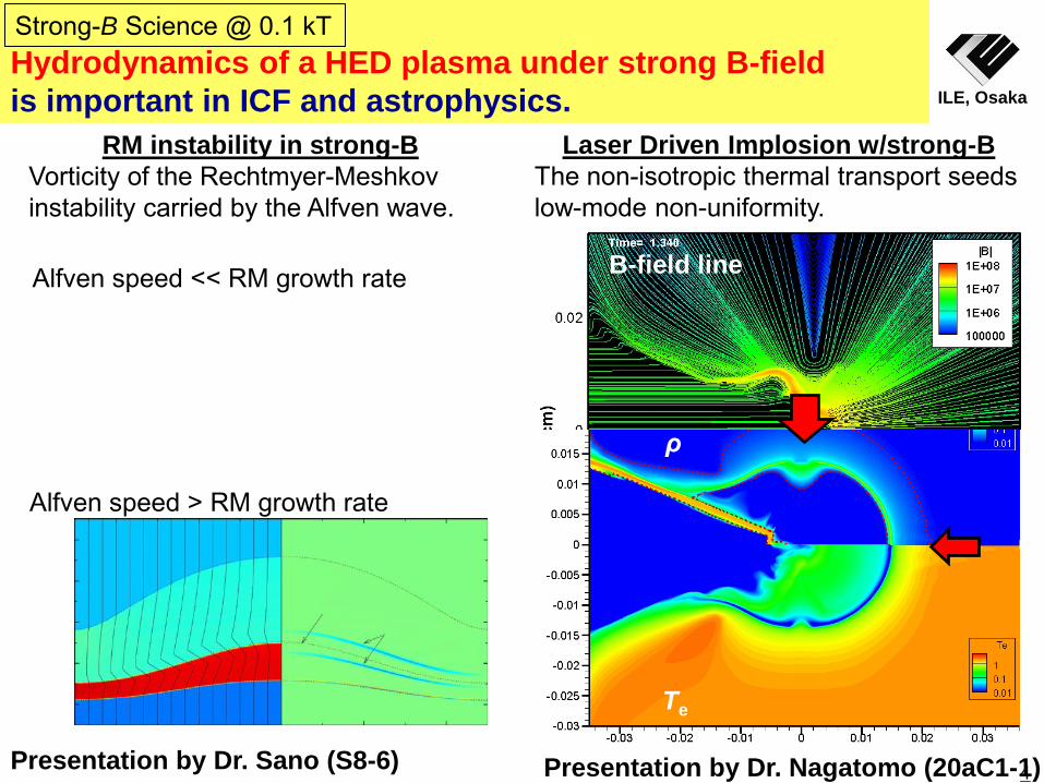
Hydrodynamics of a HED plasma under strong B-field is important in ICF and astrophysics. ILE, Osaka
Alfven speed << RM growth rate
Alfven speed > RM growth rate
RM instability in strong-B Vorticity of the Rechtmyer-Meshkov instability carried by the Alfven wave.
Strong-B Science @ 0.1 kT
Laser Driven Implosion w/strong-B The non-isotropic thermal transport seeds low-mode non-uniformity.
B-field line
ρ
Te
Presentation by Dr. Sano (S8-6) Presentation by Dr. Nagatomo (20aC1-1) 4
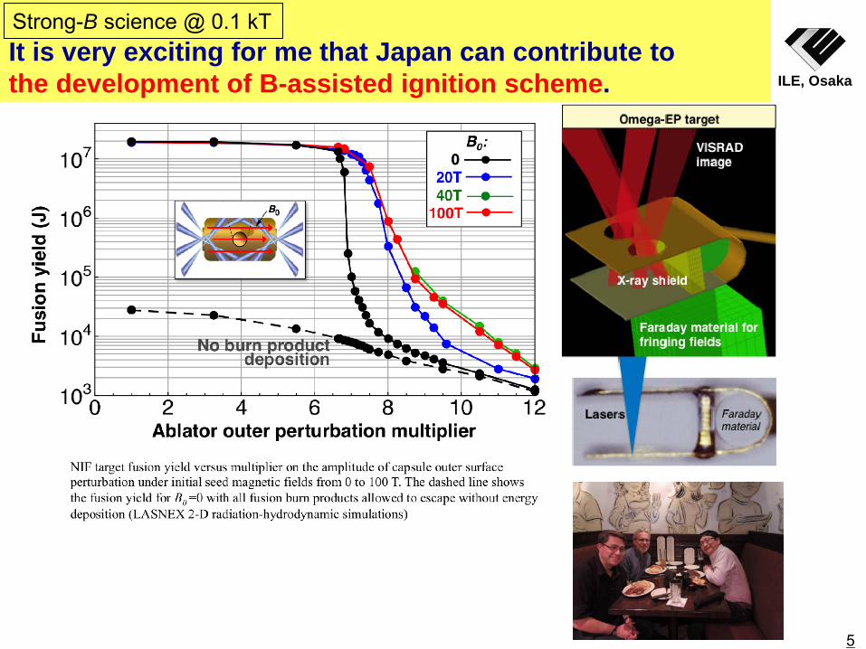
It is very exciting for me that Japan can contribute to the development of B-assisted ignition scheme. ILE, Osaka
Strong-B science @ 0.1 kT
5

LLNL-PRES-xxxxxx 6
Solenoid loop current
Laser-driven magnetic field generation schemes can provide ~100 T on ns-timescales
This is similar to a ConA target platform with backlighter configuration
10 mm Blow-off plasma
Magnetic field drive lasers
Current
Laser driven plasma sheath creates voltage source for current
eφ ∼ kbTe
• Alternative to pulsed power • Fast rise time (≤ τlaser) • Integrated into the target
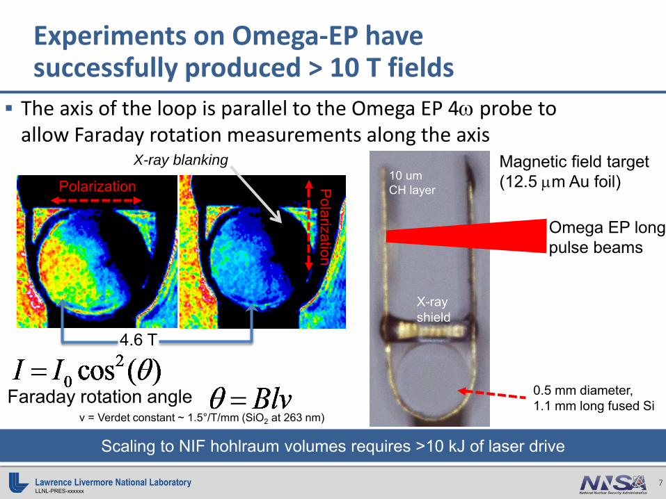
LLNL-PRES-xxxxxx 7
Faraday rotation angle
Experiments on Omega-EP have successfully produced > 10 T fields
The axis of the loop is parallel to the Omega EP 4ω probe to allow Faraday rotation measurements along the axis
Magnetic field target (12.5 µm Au foil)
Omega EP long pulse beams
10 um CH layer
X-ray shield
0.5 mm diameter, 1.1 mm long fused Si
Polarization Polarization
4.6 T
Scaling to NIF hohlraum volumes requires >10 kJ of laser drive
v = Verdet constant ~ 1.5°/T/mm (SiO2 at 263 nm)
X-ray blanking
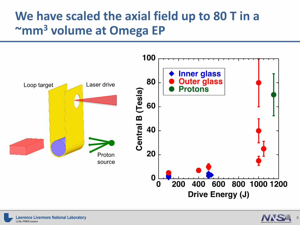
LLNL-PRES-xxxxxx 8
We have scaled the axial field up to 80 T in a ~mm3 volume at Omega EP
Proton source
Loop target Laser drive
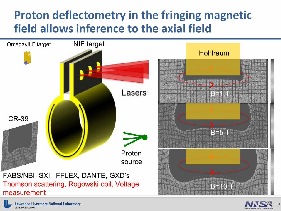
LLNL-PRES-xxxxxx 9
Proton deflectometry in the fringing magnetic field allows inference to the axial field
Proton source
CR-39
B=5 T
B=1 T
B=10 T
Hohlraum
FABS/NBI, SXI, FFLEX, DANTE, GXD’s Thomson scattering, Rogowski coil, Voltage measurement
Omega/JLF target NIF target

040
80120
160
0 0 0 0 0 0
w/o B-field
Laser-generated REB was pinched by externally imposed kT magnetic field. ILE, Osaka
w/o B-field
040
80120
160
with B-field
0 40 80 120 1600
0
0
0
0
0
0
with B-field
22 µm
15 µm
0 40 80 120 160 Horizontal position (µm)
0 40
80
12
0 16
0
0 40
80
12
0 16
0
0 40 80 120 160 Horizontal position (µm)
Verti
cal p
ositi
on (µ
m)
Verti
cal p
ositi
on (µ
m) 10 µm
Spatial Profile of Coherent Transition Radiation Significant (x8) intensity enhancement and small hot spot were observed.
Santos et al., Fr.O.3.2
10
Strong-B science @ 1 kT
w/o Bext w/ Bext
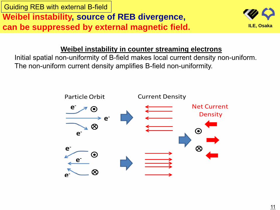
Weibel instability, source of REB divergence, can be suppressed by external magnetic field.
Guiding REB with external B-field
ILE, Osaka
Weibel instability in counter streaming electrons Initial spatial non-uniformity of B-field makes local current density non-uniform. The non-uniform current density amplifies B-field non-uniformity.
11
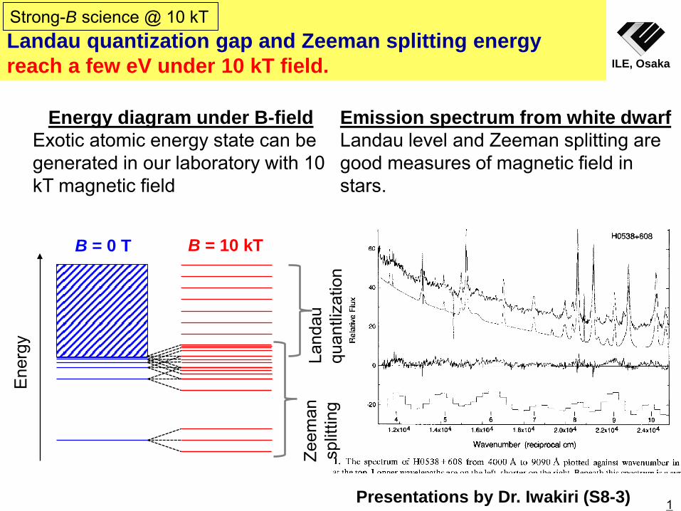
Landau quantization gap and Zeeman splitting energy reach a few eV under 10 kT field. ILE, Osaka
Energy diagram under B-field Exotic atomic energy state can be generated in our laboratory with 10 kT magnetic field
Emission spectrum from white dwarf Landau level and Zeeman splitting are good measures of magnetic field in stars.
Ene
rgy
B = 0 T B = 10 kT
Land
au
quan
tliza
tion
Zeem
an
split
ting
Strong-B science @ 10 kT
Presentations by Dr. Iwakiri (S8-3) 1

Hydrogen atom
1st Zeeman effect =1/2 m B
2nd Zeeman effect ≠1/2 m B
B. N. Murdin et al., Nature Communications, Vol. 4, p. 1469 (2013).
ILE, Osaka
2nd order Zeeman effect becomes significant with 10s kT of magnetic field.
1
Strong-B science @ 10 kT
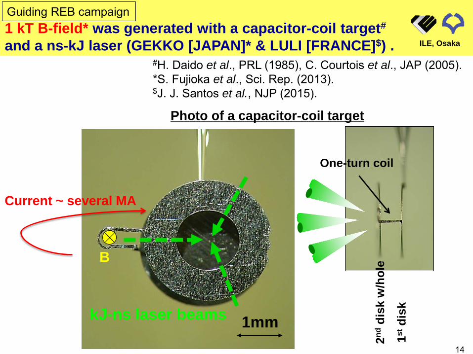
1 kT B-field* was generated with a capacitor-coil target# and a ns-kJ laser (GEKKO [JAPAN]* & LULI [FRANCE]$) .
#H. Daido et al., PRL (1985), C. Courtois et al., JAP (2005). *S. Fujioka et al., Sci. Rep. (2013). $J. J. Santos et al., NJP (2015).
1mm
B
Current ~ several MA
kJ-ns laser beams
2nd d
isk
w/h
ole
1st d
isk
One-turn coil
ILE, Osaka
14
Guiding REB campaign
Photo of a capacitor-coil target
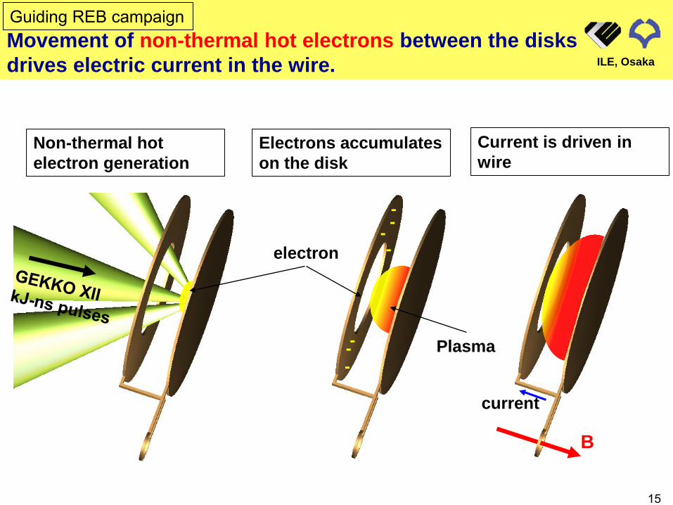
Movement of non-thermal hot electrons between the disks drives electric current in the wire.
electron
Plasma
- - -
- - -
-
B
current
Non-thermal hot electron generation
Electrons accumulates on the disk
Current is driven in wire
ILE, Osaka
15
Guiding REB campaign
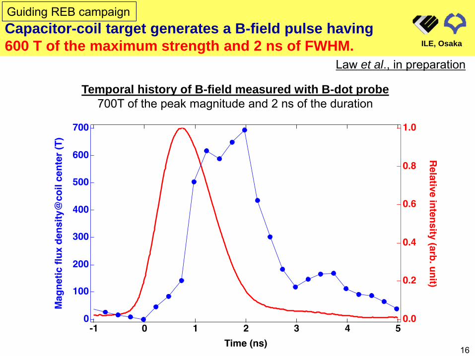
Capacitor-coil target generates a B-field pulse having 600 T of the maximum strength and 2 ns of FWHM. ILE, Osaka
Temporal history of B-field measured with B-dot probe 700T of the peak magnitude and 2 ns of the duration
16
Guiding REB campaign
Law et al., in preparation
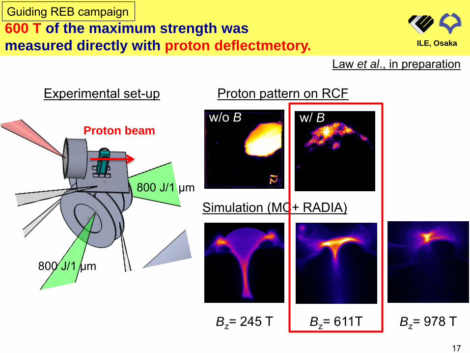
Proton beam
Bz= 245 T Bz= 611T Bz= 978 T
Simulation (MC+ RADIA)
Proton pattern on RCF
w/o B w/ B
600 T of the maximum strength was measured directly with proton deflectmetory. ILE, Osaka
17
Guiding REB campaign
800 J/1 µm
800 J/1 µm
Experimental set-up
Law et al., in preparation

The central hole of a coil remains during B-pulse duration (0 – 3 ns). ILE, Osaka
1.0 ns 1.5 ns 2.0 ns 3.0 ns
4.0 ns 4.5 ns 5.0 ns 7.0 ns
2D shadowgraph of exploding coil Gate width of 2D shadow is 250 ps.
500 µm
End
of B
-pul
se
18
Guiding REB campaign@LULI

B
Thermal conductivity becomes anisotropic under strong B-field.
kperp
kpara
kpara = kw/o B kperp = k w/o B/(1+(ωceτe)2) kw/o B : conductivity (w/o B) ωce : elec. gyrofrequency τe : elec. collisional time Te = 100 eV, ne = 9 x 1021 cm-3 ωceτe ~ 1
Thermal conductivity in parallel B-field
Braginskii coefficient
ILE, Osaka
19
Hydrodynamics in strong B-field
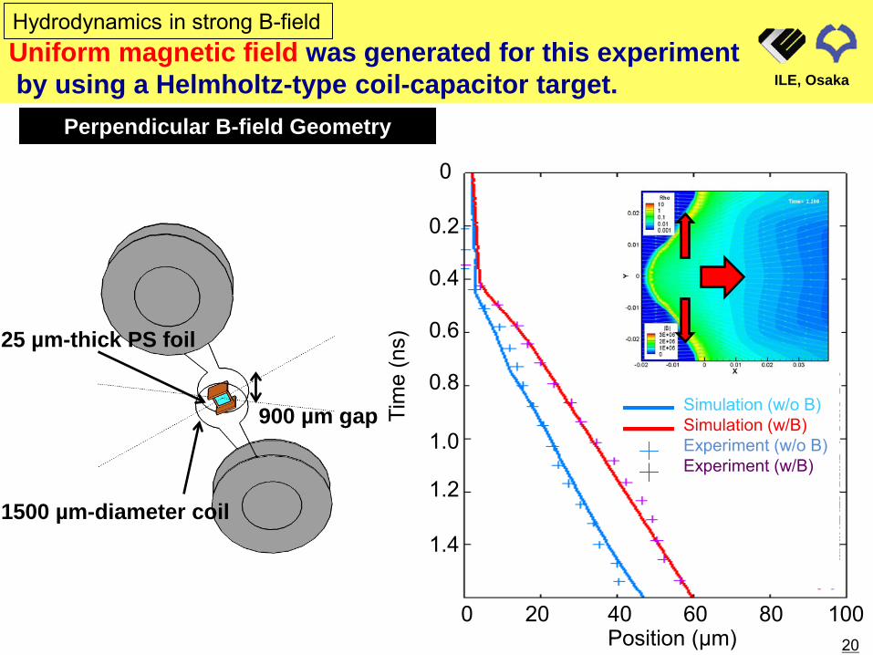
Uniform magnetic field was generated for this experiment by using a Helmholtz-type coil-capacitor target.
1500 µm-diameter coil
900 µm gap
25 µm-thick PS foil
Perpendicular B-field Geometry
ILE, Osaka
20
Hydrodynamics in strong B-field
Position (µm)
Simulation (w/o B) Simulation (w/B) Experiment (w/o B) Experiment (w/B)
Tim
e (n
s)
0
0.2
0.4
0.6
0.8
1.0
1.2
1.4
0 20 40 60 80 100
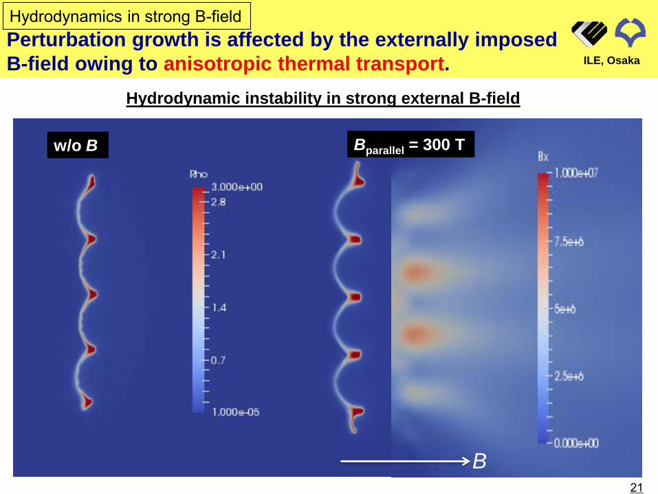
Perturbation growth is affected by the externally imposed B-field owing to anisotropic thermal transport. ILE, Osaka
21
Hydrodynamic instability in strong external B-field
w/o B Bparallel = 300 T
B
Hydrodynamics in strong B-field
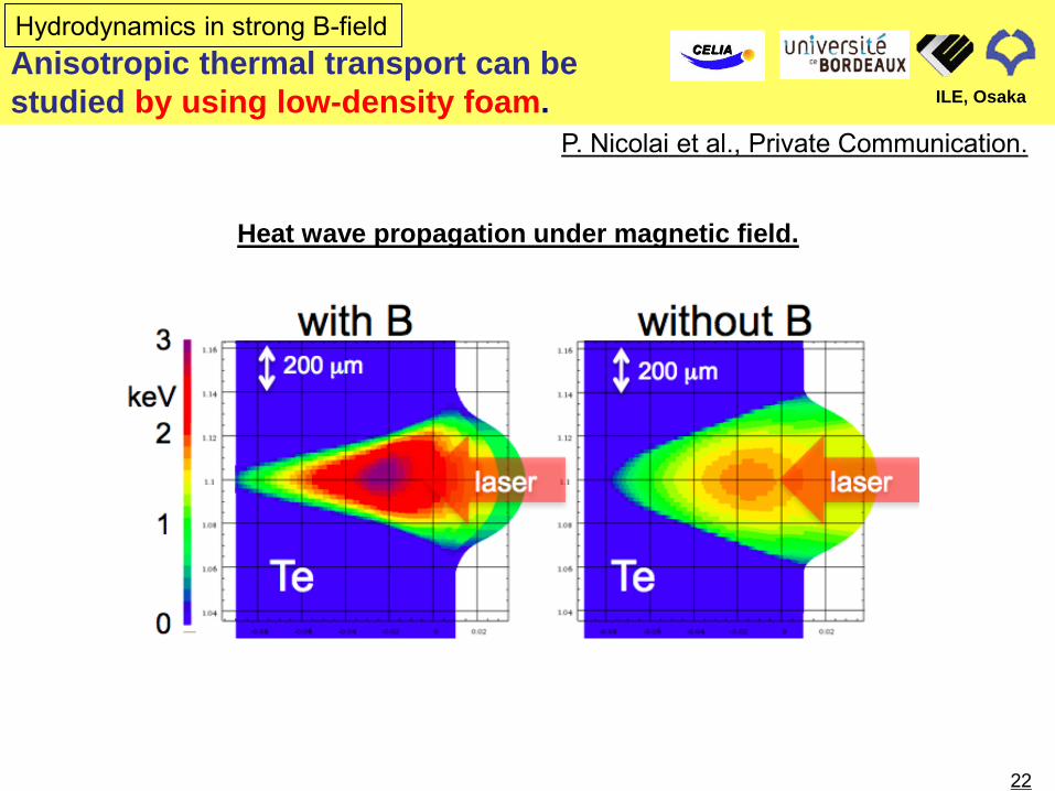
Anisotropic thermal transport can be studied by using low-density foam. ILE, Osaka
22
Heat wave propagation under magnetic field.
P. Nicolai et al., Private Communication.
Hydrodynamics in strong B-field
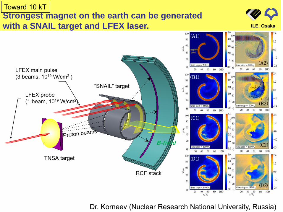
Strongest magnet on the earth can be generated with a SNAIL target and LFEX laser.
20 kT@Max
TNSA target
0
LFEX main pulse (3 beams, 1019 W/cm2 )
LFEX probe (1 beam, 1019 W/cm2)
“SNAIL” target
RCF stack
B-field
Dr. Korneev (Nuclear Research National University, Russia)
ILE, Osaka
Toward 10 kT

Generation of kilo-tesla B-field Kilo-Tesla B-field is generated with the laser-driven capacitor-coil scheme. Strength (600 – 700 T) of B-field is characterized by using a B-dot probe and
proton defractmetory.
Strong-B field science Hydrodynamics and thermal transport with 0.1 kT. B-assisted central ignition and fast ignition with 1 kT. Atomic physics with >10 kT. High energy astrophysics with >100 kT.
Plasma hydrodynamics under strong magnetic field
A thin plastic foil is accelerated by laser beams under strong magnetic field. Flying velocity of the laser-driven plastic foil is 50% faster in the magnetic field
compared to that in normal conditions. Growth of hydrodynamic instability may be accelerated in the strong magnetic
field.
Thermal transport under strong magnetic field Anisotropic thermal conduction plays important roles in the magnetized
plasma. Anisotropic thermal conduction can be studied more directly by using a low-
density foam target.
SUMMARY
24

Electrons traveling with a plasma expansion front# are accumulated on the capacitor disk.
Strong-B Generation
ni (x) ne (x)
Rarefaction wave front
Ion expansion front
Total charge density (/cm2) at the front is -σ
LASER
#P. Mora, PRL (2003).
Position (normalized) Cha
rge
dens
ity (/
cm2 )
0
-2σ
σ σ
Drawing of C-C target Plasma profile between disks
ILE, Osaka
25
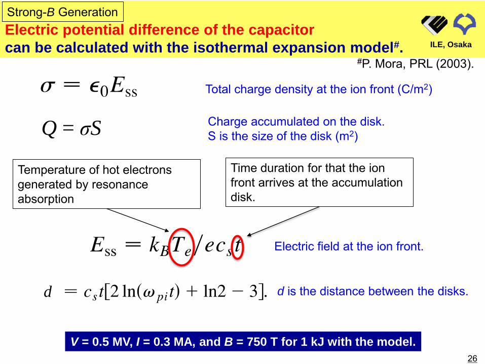
Electric potential difference of the capacitor can be calculated with the isothermal expansion model#.
Strong-B Generation
Total charge density at the ion front (C/m2)
Q = σS Charge accumulated on the disk. S is the size of the disk (m2)
Electric field at the ion front.
Temperature of hot electrons generated by resonance absorption
Time duration for that the ion front arrives at the accumulation disk.
d d is the distance between the disks.
V = 0.5 MV, I = 0.3 MA, and B = 750 T for 1 kJ with the model.
#P. Mora, PRL (2003).
ILE, Osaka
26
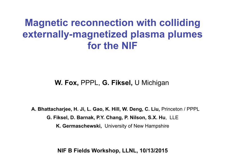
WFox IAU 2015
Magnetic reconnection with colliding externally-magnetized plasma plumes
for the NIF
W. Fox, PPPL, G. Fiksel, U Michigan !!
A. Bhattacharjee, H. Ji, L. Gao, K. Hill, W. Deng, C. Liu, Princeton / PPPL G. Fiksel, D. Barnak, P.Y. Chang, P. Nilson, S.X. Hu, LLE
K. Germaschewski, University of New Hampshire !!
NIF B Fields Workshop, LLNL, 10/13/2015

WFox IAU 2015
Laser-driven reconnection experiments with externally applied fields developed for OMEGA EP
• Previous magnetic reconnection experiments have been developed, based on self-generated (Biermann battery) magnetic fields [Nilson PRL 2006, Li PRL 2007, Rosenberg Nat Comm 2014, Zhong Nat Phys 2010]
• A new method with externally-controlled B field experiments developed for OMEGA EP using MIFEDS. First experiments demonstrated current sheet formation [Fiksel PRL 2014].
• Some advantages of externally controlled B fields:
• controlled application of B field, and initial condition. Possibly can store more magnetic flux into system than when self-generated
• compare to“null” experiments, with parallel B fields (non-reconnecting topology), or zero B fields (observation of Weibel instability by Fox PRL 2013)
• Amenable to 2-d end-to-end PIC simulations
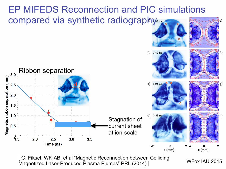
WFox IAU 2015[ G. Fiksel, WF, AB, et al “Magnetic Reconnection between Colliding Magnetized Laser-Produced Plasma Plumes” PRL (2014) ]
Ribbon separation
Stagnation of current sheet at ion-scale
EP MIFEDS Reconnection and PIC simulations compared via synthetic radiography
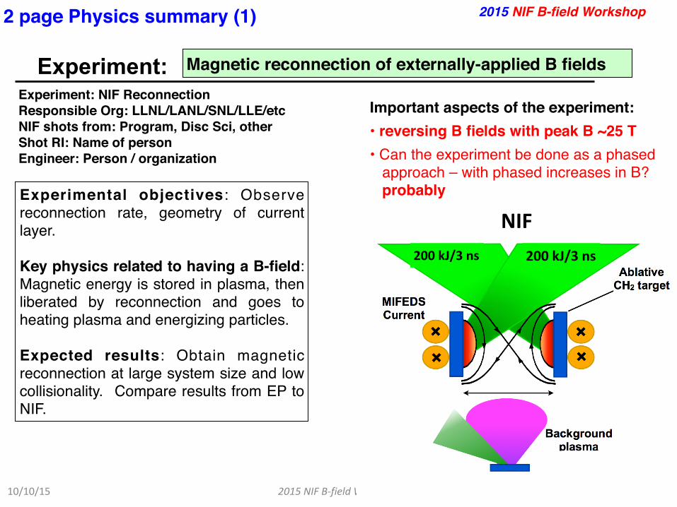
2015NIFB-fieldWorkshop
Experiment:
10/10/154
Magnetic reconnection of externally-applied B fields
2015 NIF B-field Workshop
Experiment: NIF Reconnection!Responsible Org: LLNL/LANL/SNL/LLE/etc!NIF shots from: Program, Disc Sci, other!Shot RI: Name of person!Engineer: Person / organization
Important aspects of the experiment:!• reversing B fields with peak B ~25 T!• Can the experiment be done as a phased
approach – with phased increases in B? probablyExperimental objectives: Observe
reconnection rate, geometry of current layer.!!Key physics related to having a B-field: Magnetic energy is stored in plasma, then liberated by reconnection and goes to heating plasma and energizing particles.!!Expected results: Obtain magnetic reconnection at large system size and low collisionality. Compare results from EP to NIF.
2 page Physics summary (1)
Figureshowingbasicsoftheexperiment
NIF
200kJ/3ns 200kJ/3ns
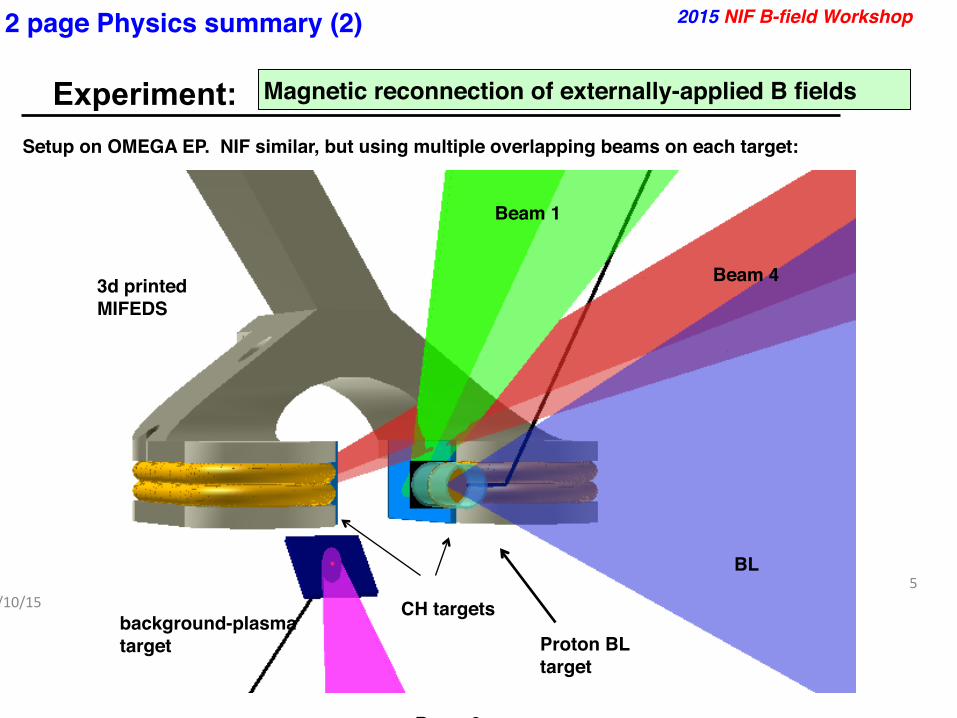
2015NIFB-fieldWorkshop
Experiment:
10/10/155
Magnetic reconnection of externally-applied B fields
2 page Physics summary (2)
Additionalfigures
2015 NIF B-field Workshop
background-plasma!target
Beam 3
Proton BL!target
BL
Beam 1
Beam 4
CH targets
3d printed!MIFEDS
Setup on OMEGA EP. NIF similar, but using multiple overlapping beams on each target:
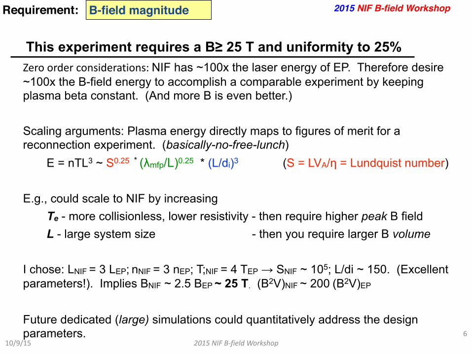
2015NIFB-fieldWorkshop
This experiment requires a B≥ 25 T and uniformity to 25%
10/9/156
B-field magnitudeRequirement:
Zeroorderconsiderations:NIF has ~100x the laser energy of EP. Therefore desire ~100x the B-field energy to accomplish a comparable experiment by keeping plasma beta constant. (And more B is even better.) !Scaling arguments: Plasma energy directly maps to figures of merit for a reconnection experiment. (basically-no-free-lunch) E = nTL3 ~ S0.25 * (λmfp/L)0.25 * (L/di)3 (S = LVA/η = Lundquist number) !E.g., could scale to NIF by increasing Te - more collisionless, lower resistivity - then require higher peak B field L - large system size - then you require larger B volume !I chose: LNIF = 3 LEP; nNIF = 3 nEP; T;NIF = 4 TEP → SNIF ~ 105; L/di ~ 150. (Excellent parameters!). Implies BNIF ~ 2.5 BEP ~ 25 T. (B2V)NIF ~ 200(B2V)EP !Future dedicated (large) simulations could quantitatively address the design parameters.
!
2015 NIF B-field Workshop
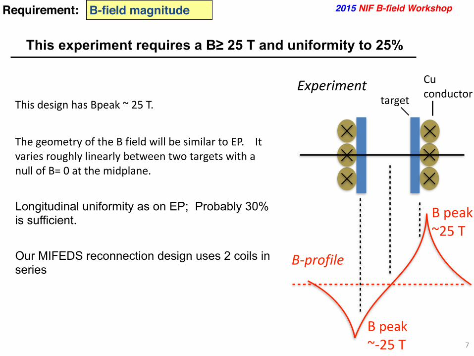
7
ThisdesignhasBpeak~25T.!ThegeometryoftheBfieldwillbesimilartoEP.ItvariesroughlylinearlybetweentwotargetswithanullofB=0atthemidplane. !Longitudinal uniformity as on EP; Probably 30% is sufficient. !Our MIFEDS reconnection design uses 2 coils in series
This experiment requires a B≥ 25 T and uniformity to 25%
B-field magnitudeRequirement: 2015 NIF B-field Workshop
B-profile
Bpeak~25T
Bpeak~-25T
Experimenttarget
Cuconductor

2015NIFB-fieldWorkshop
This experiment requires a magnetized volume of ~50 cm3
10/10/158
B-field spatial extentRequirement:
!!Critical experimental volume to magnetize for on NIF is ~3 cm3. However significant “extra” volume is magnetized to close currents. !Total Magnetized volume on EP is a few cm3. Scaling up by factor 3 in linear dimension for NIF, so perhaps ~50 cm3
total!!!!!
2015 NIF B-field Workshop
2.leftcoil 4.rtcoil
3.overbridge
MIFEDS reconnection on EP
1.downtransmissionline
5.returntransmission
line
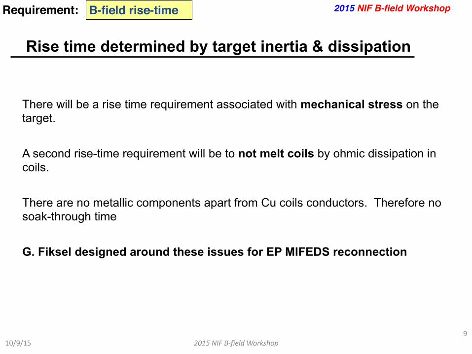
2015NIFB-fieldWorkshop
Rise time determined by target inertia & dissipation
10/9/159
B-field rise-timeRequirement:
There will be a rise time requirement associated with mechanical stress on the target. !A second rise-time requirement will be to not melt coils by ohmic dissipation in coils. !There are no metallic components apart from Cu coils conductors. Therefore no soak-through time !G. Fiksel designed around these issues for EP MIFEDS reconnection !
2015 NIF B-field Workshop

2015NIFB-fieldWorkshop
This experiment requires diagnostic access for these measurements…
10/9/1510
Diagnostic accessRequirement:
The OMEGA EP experiments have an open geometry so diagnostic access has been typically easy. !Proton radiography. Want to send proton beam along current sheet. Detectors would go on an equatorial DIM, with Dh3 proton source on opposite side of experiment !Optical interferometry. On OMEGA EP, this required rotating MIFEDS coils off from the horizontal plane to align with probe beam. !Thomson scattering. !X-ray plasma temperature measurements
2015 NIF B-field Workshop

2015NIFB-fieldWorkshop
Bring up any other issues
10/9/1511
Other issuesRequirement:
!!OMEGA EP requires the MIFEDS reconnection experiments to run with a disposable debris shield over the short-pulse backlighter parabola due to large target mass !!!
2015 NIF B-field Workshop

2015NIFB-fieldWorkshop
Experiment:
10/9/1512
Magnetic reconnection of externally-applied B fields
Summary
SummaryexperimentsketchB-field magnitude 25 T peak values
B-field spatial shape / extent
reversing profile. Experimental volume ~ 3-4 cm
B-field uniformity 25% over the required volume
B-field rise time tbd
Diagnostic access Proton backlighter, x-ray, particle detector, optical interferometry and TS
Other Significant target mass
Summaryrequirements
2015 NIF B-field Workshop
12mm
~200kJ/3ns
tbd
~200kJ/3ns

(Easy, first) design based on geometric similarity scaling
13
NIF
12mm
200kJ/3ns
tbd
200kJ/3ns
EP

Experiment:
10/23/2015 2015 NIF B-field Workshop 1
Pair confinement using a mirror magnetic field
2015 NIF B-field Workshop
Experiment: Pair confinement on NIF Responsible Org: LLNL/Uni. Michigan NIF shots from: TBD Shot RI: Hui Chen and Gennady Fiksel Engineer: TBD
Important aspects of the experiment: • Need mirror geometry >30 T B-fields • Experiment date TBD • The experiment can be done as a
phased approach: the start point is pair collimation that needs <10 T field with single coil; then procced to double coils with ramping B-fields.
Experimental objectives: Establish a novel platform for basic science experiment on NIF. Key physics related to having a B-field: First demonstration of pair confinement in the laboratory
2 page Physics summary (1)
Summary experiment sketch
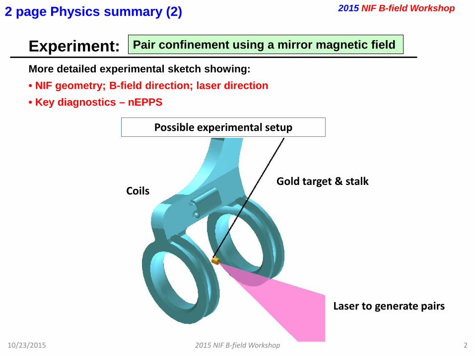
Experiment:
10/23/2015 2015 NIF B-field Workshop 2
Pair confinement using a mirror magnetic field
2 page Physics summary (2)
More detailed experimental sketch showing: • NIF geometry; B-field direction; laser direction • Key diagnostics – nEPPS
2015 NIF B-field Workshop
Coils
Laser to generate pairs
Gold target & stalk
Possible experimental setup
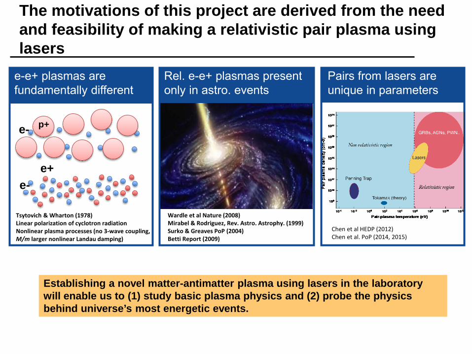
The motivations of this project are derived from the need and feasibility of making a relativistic pair plasma using lasers
e-e+ plasmas are fundamentally different
p+ e-
e- e+
Tsytovich & Wharton (1978) Linear polarization of cyclotron radiation Nonlinear plasma processes (no 3-wave coupling, M/m larger nonlinear Landau damping)
Rel. e-e+ plasmas present only in astro. events
Wardle et al Nature (2008) Mirabel & Rodriguez, Rev. Astro. Astrophy. (1999) Surko & Greaves PoP (2004) Betti Report (2009)
Establishing a novel matter-antimatter plasma using lasers in the laboratory will enable us to (1) study basic plasma physics and (2) probe the physics behind universe’s most energetic events.
Pairs from lasers are unique in parameters
Chen et al HEDP (2012) Chen et al. PoP (2014, 2015)
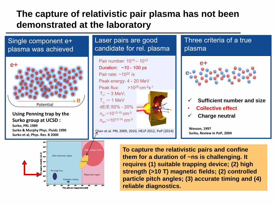
The capture of relativistic pair plasma has not been demonstrated at the laboratory
To capture the relativistic pairs and confine them for a duration of ~ns is challenging. It requires (1) suitable trapping device; (2) high strength (>10 T) magnetic fields; (2) controlled particle pitch angles; (3) accurate timing and (4) reliable diagnostics.
Three criteria of a true plasma
Wesson, 1997 Surko, Review in PoP, 2004
e- e+
Sufficient number and size • Collective effect Charge neutral
Single component e+ plasma was achieved
e+
Using Penning trap by the Surko group at UCSD : Surko, PRL 1989 Surko & Murphy Phys. Fluids 1990 Surko et al, Phys. Res. B 2000
Potential B
Laser pairs are good candidate for rel. plasma
Chen et al. PRL 2009, 2010, HELP 2012, PoP (2014)
T//: ~ 3 MeV; T
:~ 1 MeV
dE/E:50% - 20% ne-:~1013-15 cm-3 ne+:~1012-14 cm-3
Pair number: 1010 – 1012 Duration: ~10 - 100 ps Pair rate: ~1022 /s Peak energy: 4 - 20 MeV Peak flux: >1025 cm-2s-1
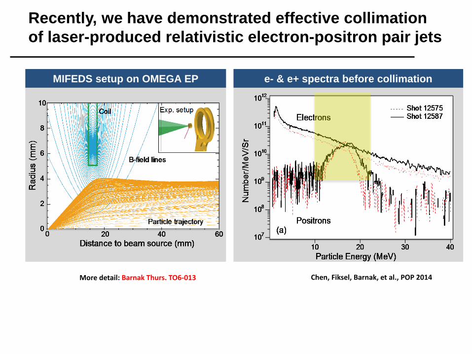
Recently, we have demonstrated effective collimation of laser-produced relativistic electron-positron pair jets
MIFEDS setup on OMEGA EP e- & e+ spectra before collimation
Chen, Fiksel, Barnak, et al., POP 2014 More detail: Barnak Thurs. TO6-013
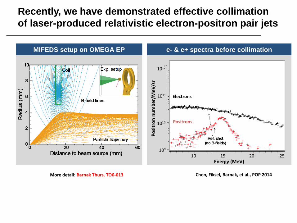
Recently, we have demonstrated effective collimation of laser-produced relativistic electron-positron pair jets
MIFEDS setup on OMEGA EP e- & e+ spectra before collimation
Chen, Fiksel, Barnak, et al., POP 2014 More detail: Barnak Thurs. TO6-013
Posi
tron
num
ber/
MeV
/sr
109
1010
1011
1012
Energy (MeV) 10 15 20 25
Electrons
Positrons

Recently, we have demonstrated effective collimation of laser-produced relativistic electron-positron pair jets
MIFEDS setup on OMEGA EP e- & e+ spectra after collimation
Chen, Fiksel, Barnak, et al., POP 2014 More detail: Barnak Thurs. TO6-013
Posi
tron
num
ber/
MeV
/sr
109
1010
1011
1012
Energy (MeV) 10 15 20 25
Electrons
Positrons
Electrons
Positrons
• The effective divergence of the beam reduced from 30 deg FWHM to 5 deg; • The charge (e-/e+) ratio in the beam reduced from ~100 to 5.
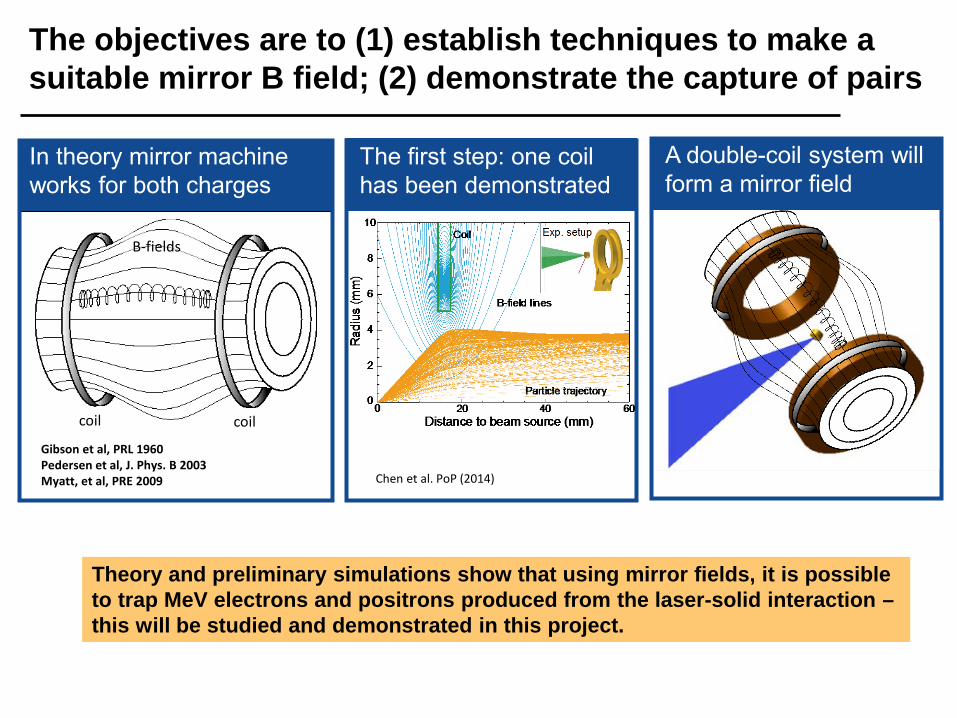
The objectives are to (1) establish techniques to make a suitable mirror B field; (2) demonstrate the capture of pairs
In theory mirror machine works for both charges
Gibson et al, PRL 1960 Pedersen et al, J. Phys. B 2003 Myatt, et al, PRE 2009
The first step: one coil has been demonstrated
Chen et al. PoP (2014)
Theory and preliminary simulations show that using mirror fields, it is possible to trap MeV electrons and positrons produced from the laser-solid interaction – this will be studied and demonstrated in this project.
A double-coil system will form a mirror field
coil coil
B-fields
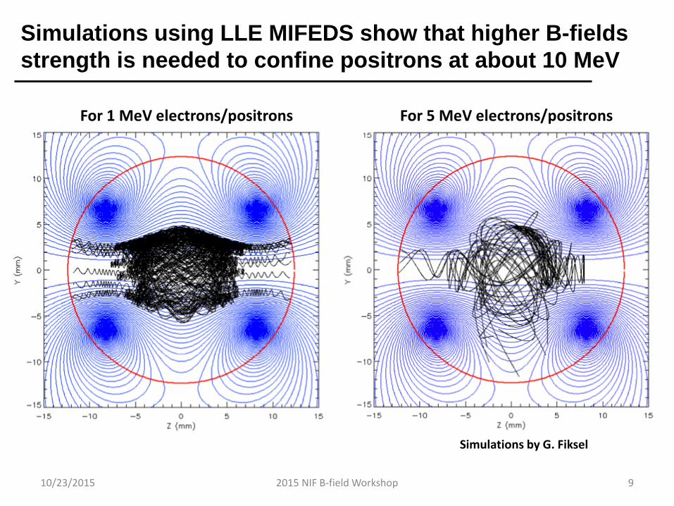
Simulations using LLE MIFEDS show that higher B-fields strength is needed to confine positrons at about 10 MeV
10/23/2015 2015 NIF B-field Workshop 9
Simulations by G. Fiksel
For 1 MeV electrons/positrons For 5 MeV electrons/positrons
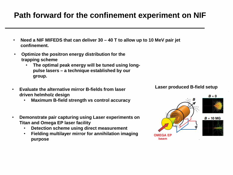
Path forward for the confinement experiment on NIF
• Optimize the positron energy distribution for the trapping scheme
• The optimal peak energy will be tuned using long-pulse lasers – a technique established by our group.
• Need a NIF MIFEDS that can deliver 30 – 40 T to allow up to 10 MeV pair jet confinement.
Laser produced B-field setup • Evaluate the alternative mirror B-fields from laser driven helmholz design
• Maximum B-field strength vs control accuracy
• Demonstrate pair capturing using Laser experiments on
Titan and Omega EP laser facility • Detection scheme using direct measurement • Fielding multilayer mirror for annihilation imaging
purpose

This experiment requires a B≥ 10 T and uniformity to 25%
10/23/2015 2015 NIF B-field Workshop 11
B-field magnitude Requirement:
One slide: B-field magnitude (range is fine) B-field spatial variation requirements (Solenoidal field, Helmholtz field, Cusp field, etc) B-field spatial uniformity requirements
2015 NIF B-field Workshop
This experiment requires a magnetized volume of 1 cm3
10/23/2015 2015 NIF B-field Workshop 12
B-field spatial extent Requirement:
One slide: Approximate magnetized volume Spatial shape of magnetized region Proposed source current path for achieving this
2015 NIF B-field Workshop
This experiment requires the field to turn on no faster than 2 µs
10/23/2015 2015 NIF B-field Workshop 13
B-field rise-time Requirement:
One slide: Rise-time considerations (soak-in time, target distortions, etc) Rise time requirements
2015 NIF B-field Workshop
This experiment requires diagnostic access for these measurements…
10/23/2015 2015 NIF B-field Workshop 14
Diagnostic access Requirement:
One slide: Key measurements requiring diagnostic access Recommendations for achieving this
2015 NIF B-field Workshop

Bring up any other issues
10/23/2015 2015 NIF B-field Workshop 15
Other issues Requirement:
One slide: Machine safety considerations (debris, laser damage, backscatter, diagnostic damage risk, etc) Feel free to share insights on working out solutions to any of these issues
2015 NIF B-field Workshop

Experiment:
10/23/2015 2015 NIF B-field Workshop 16
Few word descriptive name of the experiment
Summary
Summary experiment sketch
Figure showing basics of the experiment
B-field magnitude 10 - 30 T
B-field spatial shape / extent
1 cm3; cusp field shape
B-field uniformity 25% over the required volume
B-field rise time 2 µs
Diagnostic access X-ray spectroscopy at several positions
Other None
Summary requirements
2015 NIF B-field Workshop