document>b
TRANSCRIPT

>B< PressPress Fit System
Technical Guide

For more than 100 years, Conex Bänninger has been the recognised leader in plumbing fittings, accessories and valves globally – offering a range of innovative and highly versatile jointing solutions.
Since opening its doors in Giessen, Germany in 1909, Conex Bänninger has produced over 20 billion copper fittings, establishing an unrivalled reputation for outstanding quality, first class customer service and market leading expertise.
Passionate about excellence, Conex Bänninger is the name professionals trust for domestic, commercial, industrial, air conditioning and refrigeration applications worldwide. Conex Bänninger is an ISO 9000 assured company, which assures you the very best in quality.
100 Years of Innovation
Fast Facts20 billion fittings sold worldwide since 1909
Conex Bänninger >B< mark introduced in 1920
850 staff working across the globe
Produce 500 million pieces a year

ContentsKey Features 4-5
Applications 6-7
Approvals and Certification 8-9
Technical Data 10-13
Fittings 15-50mm 15
XL Fittings 65-100mm 41
Installation Requirements 59
Tools 65
FAQs 74-77

Conex Bänninger >B< Press is a versatile press fitting system for use with hard, half hard or annealed copper tube providing a secure, life long, leak-proof joint.
>B< Press fittings are quick to fit, providing a low cost installation solution. The slimline design gives an aesthetically pleasing finish with a secure, permanent joint that can’t be tampered with. >B< Press Water and Gas fittings are Watermark approved and certified to AS3688.
Key Features
AS 3688Lic No.WM-022197
4 Conex Bänninger >B< Press Technical Guide
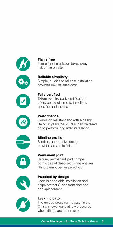
Flame free Flame free installation takes away risk of fire on site.
Reliable simplicity Simple, quick and reliable installation provides low installed cost.
Fully certified Extensive third party certification offers peace of mind to the client, specifier and installer.
Performance Corrosion resistant and with a design life of 50 years, >B< Press can be relied on to perform long after installation.
Slimline profile Slimline, unobtrusive design provides aesthetic finish.
Permanent joint Secure, permanent joint crimped both sides of deep set O-ring ensures fitting cannot be tampered with.
Practical by design Lead-in edge aids installation and helps protect O-ring from damage or displacement.
Leak Indicator The unique pressing indicator in the O-ring shows leaks at low pressures when fittings are not pressed.
Conex Bänninger >B< Press Technical Guide 5

Applications & Warranty
6 Conex Bänninger >B< Press Technical Guide

WarrantyA 25 year warranty covers against faults caused by defective manufacture of the fittings. It does not cover faults arising from incorrect installation.
The warranty covers installation with type A and B copper tube conforming to AS1432 but does not cover any faults arising from competitor fittings used on the same installation nor faults caused by damaged >B< Press fittings (through excessive pressure, for example) where competitor fittings created non-compliant conditions.
All >B< Press fittings must be installed by a licensed plumber.
Applications>B< Press Water Fittings are suitable for:
• Drinking water
• Heating water (non solar)
• Chilled water
>B< Press Gas Fittings are suitable for:
• Natural and LPG
• Compressed air (with or without oil content)
• Fuel lines
>B< Press High Temperature Fittings are suitable for:
• Solar hot water
Conex Bänninger >B< Press Technical Guide 7

Approvals & Certification
8 Conex Bänninger >B< Press Technical Guide

CertificationConex Bänninger is an ISO 9000 Quality assured company. In addition to Watermark approvals in Australia, Conex Bänninger has approvals from numerous national and international bodies including DVGW, KIWA, GASTEC, WRAS and AENOR, plus many well-known others.
Conex Bänninger >B< Press Technical Guide 9

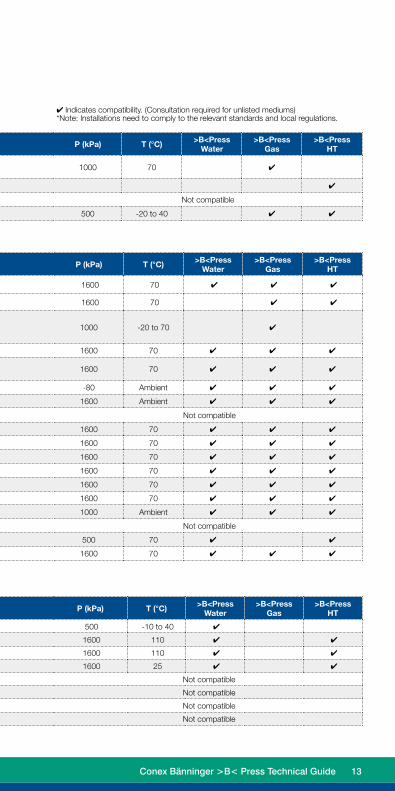
✔ Indicates compatibility. (Consultation required for unlisted mediums)
*Note: Installations need to comply to the relevant standards and local regulations. The maximum constant or standard operating pressure and temperature are shown. For testing or short spikes higher pressure and temperature may be applicable.
Technical Data
>B< Press is suitable for use with hard, half hard or annealed type A and B copper tube complying with AS1432
Anti-Freeze / Corrosion Protection / Inhibitors
Water Supply Systems
Application / MediumComments
P (kPa) T (°C) >B<Press Water
>B<Press Gas
>B<Press HT
Product Manufacturer
Anti-freeze cooling concentration 50%
Antifrogen N Clariant
1600 -25 to 110
✔
Antifrogen L Clariant ✔
Antifrogen Sol (solar systems) Clariant ✔
Ethylene Glycol (Ethan-1,2-diol) Various ✔
Propylene Glycol (1,2-Propandiol) Various ✔
Tyfoxit Tyforop-Chemie ✔
Tyfocop Tyforop-Chemie ✔
Antifrogen N Clariant
1600 -15 to 160
✔
Antifrogen L Clariant ✔
Antifrogen Sol (solar systems) Clariant ✔
Ethylene Glycol (Ethan-1,2-diol) Various ✔
Propylene Glycol (1,2-Propandiol) Various ✔
Tyfoxit Tyforop-Chemie ✔
Tyfocop Tyforop-Chemie ✔
Application / Medium Comments P (kPa) T (°C) >B<Press Water
>B<Press Gas
>B<Press HT
Hot and cold potable waterAustralian Watermark approved. Watermark
certification for all plumbing products is restricted to 1400kPa at 95°C.
1600 110 ✔ ✔
Fire ServicesCapable of the required test pressure of 1700kPa
or 1.5 times the design pressure as specified by AS2419.1
1600 110 ✔ ✔
Rainwater 1600 Ambient ✔ ✔
Pump circulated hot water systems Compliant with EN 12828 1600 110 ✔ ✔
Chilled Water 1000 5 ✔
Steam Low pressure steam equipment ≤ 100 120 ✔ ✔
Solar Collectors 1600 160 ✔
Conditioned water (partially and fully desalinised water, softened, deionised demineralised distilled)
Not compatible
10 Conex Bänninger >B< Press Technical Guide

Application / MediumComments
P (kPa) T (°C) >B<Press Water
>B<Press Gas
>B<Press HT
Product Manufacturer
Anti-freeze cooling concentration 50%
Antifrogen N Clariant
1600 -25 to 110
✔
Antifrogen L Clariant ✔
Antifrogen Sol (solar systems) Clariant ✔
Ethylene Glycol (Ethan-1,2-diol) Various ✔
Propylene Glycol (1,2-Propandiol) Various ✔
Tyfoxit Tyforop-Chemie ✔
Tyfocop Tyforop-Chemie ✔
Antifrogen N Clariant
1600 -15 to 160
✔
Antifrogen L Clariant ✔
Antifrogen Sol (solar systems) Clariant ✔
Ethylene Glycol (Ethan-1,2-diol) Various ✔
Propylene Glycol (1,2-Propandiol) Various ✔
Tyfoxit Tyforop-Chemie ✔
Tyfocop Tyforop-Chemie ✔
Application / Medium Comments P (kPa) T (°C) >B<Press Water
>B<Press Gas
>B<Press HT
Hot and cold potable waterAustralian Watermark approved. Watermark
certification for all plumbing products is restricted to 1400kPa at 95°C.
1600 110 ✔ ✔
Fire ServicesCapable of the required test pressure of 1700kPa
or 1.5 times the design pressure as specified by AS2419.1
1600 110 ✔ ✔
Rainwater 1600 Ambient ✔ ✔
Pump circulated hot water systems Compliant with EN 12828 1600 110 ✔ ✔
Chilled Water 1000 5 ✔
Steam Low pressure steam equipment ≤ 100 120 ✔ ✔
Solar Collectors 1600 160 ✔
Conditioned water (partially and fully desalinised water, softened, deionised demineralised distilled)
Not compatible
Conex Bänninger >B< Press Technical Guide 11

Application / Medium Comments P (kPa) T (°C) >B<Press Water
>B<Press Gas
>B<Press HT
Compressed AirOil Concentration < 25mg/m³ 1600 70 ✔ ✔ ✔
Oil Concentration > 25mg/m³ 1600 70 ✔ ✔
Natural Gas Liquid gas Propane Butane Methane
The scope of AS5601 for all gas systems is restricted to 200kPa. 1000 -20 to 70 ✔
Argon For welding 1600 70 ✔ ✔ ✔
Forming Gas, Dry / Welding Inert Gas Ar+CO2 (Eg Cargon) 1600 70 ✔ ✔ ✔
Vacuum -80 Ambient ✔ ✔ ✔
Carbon Dioxide (Dry Gas) Dry CO² 1600 Ambient ✔ ✔ ✔
Carbon Dioxide (Wet Gas) Not compatible
Nitrogen Nitrogen Gas 1600 70 ✔ ✔ ✔
Helium May leak at <0.001cm³ /min 1600 70 ✔ ✔ ✔
Neon 1600 70 ✔ ✔ ✔
Xenon 1600 70 ✔ ✔ ✔
Synthetic Air 1600 70 ✔ ✔ ✔
Krypton 1600 70 ✔ ✔ ✔
Oxygen 1000 Ambient ✔ ✔ ✔
Acetylene Not compatible
Hydrogen 500 70 ✔ ✔
Carbon Monoxide XL not compatible 1600 70 ✔ ✔ ✔
Gas
Oils, cooling materials and lubricants
Technical Data
>B< Press is suitable for use with hard, half hard or annealed type A and B copper tube complying with AS1432
Special Media
Application / Medium Comments P (kPa) T (°C) >B<Press Water
>B<Press Gas
>B<Press HT
Acetone Liquid 500 -10 to 40 ✔
Condensate From gas condenser boiler 1600 110 ✔ ✔
Condensate From steam 1600 110 ✔ ✔
Ethanol 1600 25 ✔ ✔
Urea Not compatible
Methanol Not compatible
Sodium Hydroxide Not compatible
Ammonia Not compatible
Application / Medium Comments P (kPa) T (°C) >B<Press Water
>B<Press Gas
>B<Press HT
Engine oils and Lubricants (Petroleum-based) Consultation required 1000 70 ✔
Engine Oils (Synthetic based) ✔
Bio Diesel Not compatible
Heating oil, Diesel in acc. with EN590 500 -20 to 40 ✔ ✔
12 Conex Bänninger >B< Press Technical Guide
✔ Indicates compatibility. (Consultation required for unlisted mediums)*Note: Installations need to comply to the relevant standards and local regulations.
Application / Medium Comments P (kPa) T (°C) >B<Press Water
>B<Press Gas
>B<Press HT
Acetone Liquid 500 -10 to 40 ✔
Condensate From gas condenser boiler 1600 110 ✔ ✔
Condensate From steam 1600 110 ✔ ✔
Ethanol 1600 25 ✔ ✔
Urea Not compatible
Methanol Not compatible
Sodium Hydroxide Not compatible
Ammonia Not compatible
Application / Medium Comments P (kPa) T (°C) >B<Press Water
>B<Press Gas
>B<Press HT
Engine oils and Lubricants (Petroleum-based) Consultation required 1000 70 ✔
Engine Oils (Synthetic based) ✔
Bio Diesel Not compatible
Heating oil, Diesel in acc. with EN590 500 -20 to 40 ✔ ✔
Application / Medium Comments P (kPa) T (°C) >B<Press Water
>B<Press Gas
>B<Press HT
Compressed AirOil Concentration < 25mg/m³ 1600 70 ✔ ✔ ✔
Oil Concentration > 25mg/m³ 1600 70 ✔ ✔
Natural Gas Liquid gas Propane Butane Methane
The scope of AS5601 for all gas systems is restricted to 200kPa. 1000 -20 to 70 ✔
Argon For welding 1600 70 ✔ ✔ ✔
Forming Gas, Dry / Welding Inert Gas Ar+CO2 (Eg Cargon) 1600 70 ✔ ✔ ✔
Vacuum -80 Ambient ✔ ✔ ✔
Carbon Dioxide (Dry Gas) Dry CO² 1600 Ambient ✔ ✔ ✔
Carbon Dioxide (Wet Gas) Not compatible
Nitrogen Nitrogen Gas 1600 70 ✔ ✔ ✔
Helium May leak at <0.001cm³ /min 1600 70 ✔ ✔ ✔
Neon 1600 70 ✔ ✔ ✔
Xenon 1600 70 ✔ ✔ ✔
Synthetic Air 1600 70 ✔ ✔ ✔
Krypton 1600 70 ✔ ✔ ✔
Oxygen 1000 Ambient ✔ ✔ ✔
Acetylene Not compatible
Hydrogen 500 70 ✔ ✔
Carbon Monoxide XL not compatible 1600 70 ✔ ✔ ✔
Conex Bänninger >B< Press Technical Guide 13


Fittings15-50mm

Product Features
O-Ring>B< Press fittings for water applications are identified with a black O-ring. For natural gas and LPG applications, fittings are identified by a yellow coloured O-ring and a yellow mark on the fitting body. *Important Note: The O-ring colour and identification must meet the application. O-ring in the fittings are not to be removed or changed.
Section through >B< Press fitting
1. Bead
2. O-ring
3. Cylindrical sleeve (socket)
4. Pressing both sides of O-ring
A. Specialist O-ring (Gas – HNBR)
B. Specialist O-ring (Water – EPDM)
A B
1 2
3 4
Water – EPDM Gas – HNBR High Temperature – FKM
16 Conex Bänninger >B< Press Technical Guide

Pressing Indicator (PI) FeatureThe unique pressing indicator is a specially designed O-ring. It has a reduced section in two positions that allows water or air past the sealing element of any unpressed connection, thereby providing a visible leakage point during the commissioning of the system.
Unpressed fittings are identified by pressurizing the system with a pressure range of 100 kPa to 500 kPa for water (prior to the final pressure testing) and 2.2 kPa to 300 kPa for gas.
When the fitting is pressed, the O-ring material compresses, filling the gaps, creating a leak free joint.
Final testing of the system should be conducted in accordance with AS/NZS 3500 and/or AS/NZS 5601.
Conex Bänninger >B< Press Technical Guide 17

Installation InstructionsTo install >B< Press, a Rothenberger Romax mechanical tool with compatible sized jaw to fit each size fitting is required. When pressure is exerted through the press tool a permanent joint is made and the fitting cannot be disassembled or re-used. The >B< Press profile has the
1. Cut the pipeWe recommend you use a Rothenberger pipe cutter. It is important to ensure that the pipe is cut completely square. Tube ends should be clean and free from scratches not less than the socket length.
2. Remove burrsMake sure that the internal and external tube end is free from burrs or sharp edges by using a deburring tool to prevent damage to the O-ring. Then wipe the tube end clean to avoid damaging the O-ring on tube insertion.
3. Ensure the O-ring is seated and lubricated
Before inserting the copper tube ensure that the O-ring is seated correctly, free from damage and lubricated. If not lubricated a small amount of water can be used to provide lubrication.
4. Mark insertion depthThe tube must be fully inserted into the fitting until it reaches the tube stop in order to make a perfect joint. Marking insertion depth will ensure that any tube movement is detected, which is especially important if the joints are to be pressed at a later time.
NOTE: As repair couplings do not have a tube stop, both ends of the tube must meet in the middle of the fitting.
18 Conex Bänninger >B< Press Technical Guide

ImportantIt is important to keep the fitting free of any dust or dirt and to ensure the O-ring stays lubricated and protected from damage. Select the correct size of tube and fitting for the job. Ensure that both are clean and free from damage and imperfections.
5. Ensure pipe is inserted up to the tube stop
To assemble the joint, the tube must be inserted into the fitting up to the tube stop. (Use the mark on the tube which was made earlier as reference.) The pressing operation should only be undertaken when the tube reaches the tube stop. When inserting turn the tube slightly to ease the tube over the O-ring.
6. Complete the joint with the compression tool
Ensure that the correct size jaw for the fitting is inserted into the tool. The jaws must be placed square on the fitting. Depress the trigger/button to begin the compression cycle of the tool. This is complete when the mouth of the fitting is fully enclosed by the jaws. Now release the jaws from around the fitting. (For further information refer to complete Romax instructions.)
NOTE: >B< Press joint is complete after one complete compression cycle of the tool Do not crimp any >B< Press fitting more than once.
advantage of a 3 Point Press making it more secure, through two presses either side of the bead and one press crimping the O-ring.
Tube Size Insertion Depth15 1718 2220 2225 2332 2540 3150 39
Conex Bänninger >B< Press Technical Guide 19

>B< Press Water
STRAIGHT CONNECTOR
Product Code Size (D1) L Z
404600 15mm 39 3
404860 18mm 49 3
404601 20mm 47 3
404602 25mm 49 3
404603 32mm 53 3
404604 40mm 64 2
404605 50mm 80 2
REPAIR COUPLING
Product Code Size (D1) L
404661 15mm 39
405098 18mm 49
404662 20mm 47
404663 25mm 49
404664 32mm 53
404665 40mm 64
404666 50mm 80
COUPLING - REDUCING
Product Code Size (D1 x D2) L1 Z
404864 18 x 15mm 43 2
404631 20 x 15mm 47 7
404863 20 x 18mm 48 4
404632 25 x 15mm 54 13
404633 25 x 20mm 52 7
404634 32 x 25mm 55 7
404635 40 x 25mm 67 13
404636 40 x 32mm 62 6
404637 50 x 25mm 86 24
404638 50 x 32mm 83 19
404639 50 x 40mm 84 14
Range
L
D1
D1
Z
L
D1
D1
D2
L
Z
20 Conex Bänninger >B< Press Technical Guide
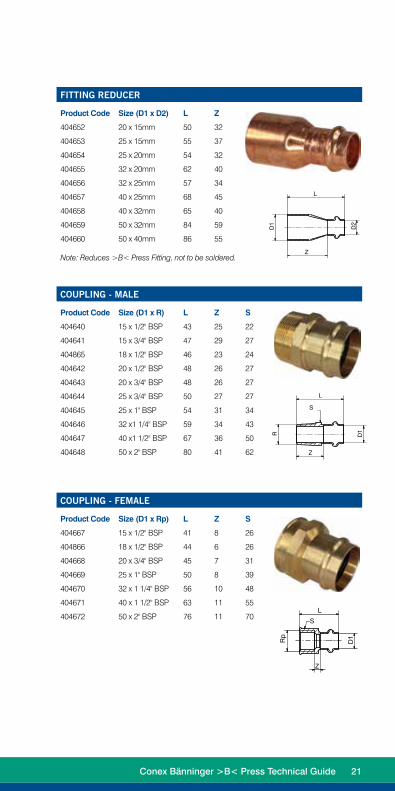
FITTING REDUCER
Product Code Size (D1 x D2) L Z
404652 20 x 15mm 50 32
404653 25 x 15mm 55 37
404654 25 x 20mm 54 32
404655 32 x 20mm 62 40
404656 32 x 25mm 57 34
404657 40 x 25mm 68 45
404658 40 x 32mm 65 40
404659 50 x 32mm 84 59
404660 50 x 40mm 86 55
Note: Reduces >B< Press Fitting, not to be soldered.
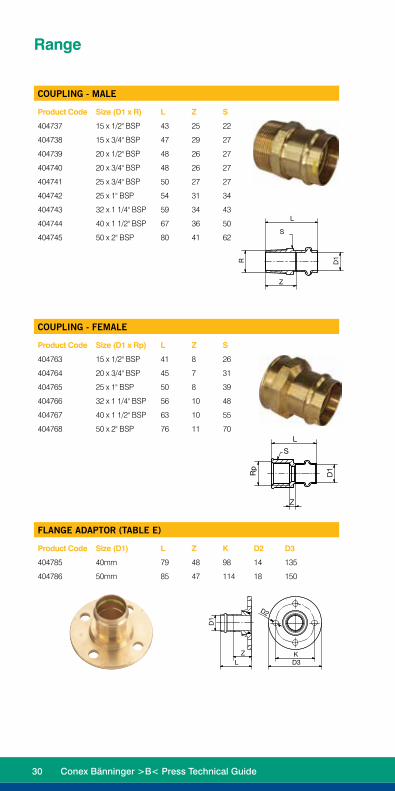
COUPLING - MALE
Product Code Size (D1 x R) L Z S
404640 15 x 1/2" BSP 43 25 22
404641 15 x 3/4" BSP 47 29 27
404865 18 x 1/2" BSP 46 23 24
404642 20 x 1/2" BSP 48 26 27
404643 20 x 3/4" BSP 48 26 27
404644 25 x 3/4" BSP 50 27 27
404645 25 x 1" BSP 54 31 34
404646 32 x1 1/4" BSP 59 34 43
404647 40 x1 1/2" BSP 67 36 50
404648 50 x 2" BSP 80 41 62
COUPLING - FEMALE
Product Code Size (D1 x Rp) L Z S
404667 15 x 1/2" BSP 41 8 26
404866 18 x 1/2" BSP 44 6 26
404668 20 x 3/4" BSP 45 7 31
404669 25 x 1" BSP 50 8 39
404670 32 x 1 1/4" BSP 56 10 48
404671 40 x 1 1/2" BSP 63 11 55
404672 50 x 2" BSP 76 11 70
D1
D2
L
Z
D1R
L
Z
S
Rp
D1
L
Z
S
Conex Bänninger >B< Press Technical Guide 21

Range
FLANGE ADAPTOR (TABLE E)
Product Code Size (D1) L Z K D2 D3
404689 40mm 79 48 98 14 135
404690 50mm 85 47 114 18 150
D1
ZL
D2
D3K
ELBOW - 90 DEG
Product Code Size (D1 x D2) L Z
404606 15mm 32 14
404861 18mm 38 15
404607 20mm 43 21
404608 25mm 53 30
404609 32mm 60 35
404610 40mm 76 45
404611 50mm 100 61
ELBOW M&F - 90 DEG
Product Code Size (D1) L Z L2
404851 15mm 32 14 34
404852 20mm 43 21 46
404853 25mm 53 30 55
404854 32mm 60 35 62
404855 40mm 76 45 78
404856 50mm 100 61 102
L
L
Z
Z
D1
D1
L1
Z
D1
D1
L2
22 Conex Bänninger >B< Press Technical Guide

ELBOW M&F - 45 DEG
Product Code Size (D1) L1 Z L2
404844 25mm 35 12 37
404845 32mm 39 14 41
404846 40mm 50 19 52
404847 50mm 64 25 66
ELBOW - 45 DEG
Product Code Size (D1) L Z
404673 25mm 35 12
404674 32mm 39 14
404675 40mm 50 19
404676 50mm 64 25
ELBOW - MALE 90 DEG
Product Code D1 x Rp L1 Z L2 S
405138 15 X 1/2" BSP 32 14 42 22
405139 20 X 3/4" BSP 43 21 51 27
ELBOW - FEMALE 90 DEG
Product Code D1 x Rp L1 Z L2 L3 S
405140 15 X 1/2" BSP 32 14 25 15 22
405141 20 X 3/4" BSP 43 21 33 16 27
D1
D1
L
L ZZ
L1
L2
Z
D1
D1
L1Z
D1
S (Oct)
R
L2
L1Z
D1
S (Oct)
Rp
L2L3
Conex Bänninger >B< Press Technical Guide 23

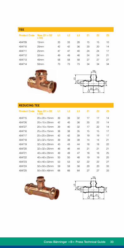
TEE
Product Code Size (D1 x D2 x D3)
L1 L2 L3 Z1 Z2 Z3
404612 15mm 33 33 28 15 15 10
404862 18mm 40 40 34 17 17 11
404613 20mm 42 42 36 20 20 14
404614 25mm 47 47 40 24 24 17
404615 32mm 49 49 46 24 24 21
404616 40mm 58 58 58 27 27 27
404617 50mm 73 73 73 34 34 34
D2
D3
D1
L2 L1Z2 Z1
L3Z
3
REDUCING TEE
Product Code Size (D1 x D2 x D3)
L1 L2 L3 Z1 Z2 Z3
404618 20 x 20 x 15mm 39 39 32 17 17 14
404629 20 x 15 x 20mm 42 40 36 20 22 14
404630 20 x 15 x 15mm 39 40 32 17 22 14
404619 25 x 25 x 15mm 38 38 35 15 15 17
404620 25 x 25 x 20mm 42 42 39 19 19 17
404621 32 x 32 x 15mm 39 39 39 14 14 21
404622 32 x 32 x 20mm 43 43 44 18 18 22
404623 32 x 32 x 25mm 46 46 44 21 21 21
404624 40 x 40 x 20mm 49 49 47 18 18 25
404625 40 x 40 x 25mm 50 50 48 19 19 25
404626 40 x 40 x 32mm 53 53 52 22 22 27
404627 50 x 50 x 25mm 59 59 56 20 20 33
404628 50 x 50 x 40mm 66 66 64 27 27 33
D2
D3
D1
L2 L1Z2 Z1
L3Z
3
Range
24 Conex Bänninger >B< Press Technical Guide

END CAP
Product Code Size (D1) L Z
404691 15mm 20 18
404949 18mm 22 20
404692 20mm 24 22
404693 25mm 25 23
404694 32mm 27 25
404695 40mm 33 31
404696 50mm 41 39
D1
ZL
WALL PLATE ELBOW - FEMALE
Product Code Size (D1 x Rp) L1 Z L2 L3 L4
404650 15 x 1/2" BSP 42 24 24 15 18
404651 20 x 3/4" BSP 47 25 27 16 24
Rp
L1 L2
L3L4
Z
D1
WALL PLATE ELBOW - MALE
Product Code Size (D1 x GB) L1 Z L2 L3 L4
404649 15 x 1/2" BSP 22 24 30 52 42
L3L2
L1
D1
GB
Z
L4
Conex Bänninger >B< Press Technical Guide 25
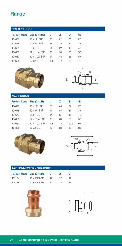
FEMALE UNION
Product Code Size (D1 x Rp) L Z S1 S2
404683 15 x 1/2" BSP 55 22 30 28
404684 20 x 3/4" BSP 68 30 37 34
404685 25 x 1" BSP 64 22 46 42
404686 32 x 1 1/4" BSP 83 38 53 50
404687 40 x 1 1/2" BSP 94 42 65 57
404688 50 x 2" BSP 106 42 83 72
Rp
D1
L
Z
S1 S2
MALE UNION
Product Code Size (D1 x R) L Z S1 S2
404677 15 x 1/2" BSP 63 46 29 27
404678 20 x 3/4" BSP 77 55 37 34
404679 25 x 1" BSP 84 61 46 43
404680 32 x 1 1/4" BSP 93 68 53 50
404681 40 x 1 1/2" BSP 106 75 65.5 64
404682 50 x 2" BSP 124 86 83 80
D1
R
L
Z
S1 S2
Range
TAP CONNECTOR - STRAIGHT
Product Code Size (D1 x R) L Z S
405134 15 X 1/2" BSP 42 27 27
405135 20 X 3/4" BSP 52 33 36
L
Z
S
26 Conex Bänninger >B< Press Technical Guide

TAP CONNECTOR - BENT
Product Code Size (D1 x R) L Z S
405136 15 X 1/2" BSP 45 35 24
405137 20 X 3/4" BSP 55 46 31
L
Z
S
AUSPEX ADAPTOR
Product Code Size
1544580 15mm
1544581 20mm
1544582 25mm
REHAU ADAPTOR
Product Code Size
405111 15mm
405112 20mm
405117 25mm
Conex Bänninger >B< Press Technical Guide 27

>B< Press Gas
STRAIGHT CONNECTOR
Product Code Size (D1) L Z
404697 15mm 39 3
404698 20mm 47 3
404699 25mm 49 3
404700 32mm 53 3
404701 40mm 64 2
404702 50mm 80 2
REPAIR COUPLING
Product Code Size (D1) L
404757 15mm 39
404758 20mm 47
404759 25mm 49
404760 32mm 53
404761 40mm 64
404762 50mm 80
L
D1
LD
1
D1
Z
Range
28 Conex Bänninger >B< Press Technical Guide

COUPLING - REDUCING
Product Code Size (D1 x D2) L1 Z
404728 20 x 15mm 47 7
404729 25 x 15mm 54 13
404730 25 x 20mm 52 7
404731 32 x 25mm 55 7
404732 40 x 25mm 67 13
404733 40 x 32mm 62 6
404734 50 x 25mm 86 24
404735 50 x 32mm 83 19
404736 50 x 40mm 84 14
FITTING REDUCER
Product Code Size (D1 x D2) L Z
404748 20 x 15mm 50 32
404749 25 x 15mm 55 37
404750 25 x 20mm 54 32
404751 32 x 20mm 62 40
404752 32 x 25mm 57 34
404753 40 x 25mm 68 45
404754 40 x 32mm 65 40
404755 50 x 32mm 84 59
404756 50 x 40mm 86 55
Note: Reduces >B< Press Fitting, not to be soldered.
D1
D2
L
Z
D1
D2
L
Z
Conex Bänninger >B< Press Technical Guide 29
COUPLING - MALE
Product Code Size (D1 x R) L Z S
404737 15 x 1/2" BSP 43 25 22
404738 15 x 3/4" BSP 47 29 27
404739 20 x 1/2" BSP 48 26 27
404740 20 x 3/4" BSP 48 26 27
404741 25 x 3/4" BSP 50 27 27
404742 25 x 1" BSP 54 31 34
404743 32 x 1 1/4" BSP 59 34 43
404744 40 x 1 1/2" BSP 67 36 50
404745 50 x 2" BSP 80 41 62
COUPLING - FEMALE
Product Code Size (D1 x Rp) L Z S
404763 15 x 1/2" BSP 41 8 26
404764 20 x 3/4" BSP 45 7 31
404765 25 x 1" BSP 50 8 39
404766 32 x 1 1/4" BSP 56 10 48
404767 40 x 1 1/2" BSP 63 10 55
404768 50 x 2" BSP 76 11 70
FLANGE ADAPTOR (TABLE E)
Product Code Size (D1) L Z K D2 D3
404785 40mm 79 48 98 14 135
404786 50mm 85 47 114 18 150
D1
ZL
D2
D3K
D1R
L
Z
S
Rp
D1
L
Z
S
Range
30 Conex Bänninger >B< Press Technical Guide

ELBOW - 90 DEG
Product Code Size (D1) L Z
404703 15mm 32 14
404704 20mm 43 21
404705 25mm 53 30
404706 32mm 60 35
404707 40mm 76 45
404708 50mm 100 61
L
L
Z
Z
D1
D1
ELBOW - 45 DEG
Product Code Size (D1) L Z
404769 25mm 35 12
404770 32mm 39 14
404771 40mm 50 19
404772 50mm 64 25
ELBOW M&F - 90 DEG
Product Code Size (D1) L1 Z L2
404917 15mm 32 14 34
404918 20mm 43 21 46
404919 25mm 53 30 55
404920 32mm 60 35 62
404921 40mm 76 45 78
404922 50mm 100 61 102
L1
Z
D1
D1
L2
D1
D1
L
L ZZ
Conex Bänninger >B< Press Technical Guide 31

ELBOW M&F - 45 DEG
Product Code Size (D1) L1 Z L2
404910 25mm 35 12 37
404911 32mm 39 14 41
404912 40mm 50 19 52
404913 50mm 64 25 66
ELBOW - MALE 90 DEG
Product Code D1 x Rp L1 Z L2 S
405146 DN15 x 1/2 32 14 42 22
405147 DN20 x 3/4 43 21 51 27
ELBOW - FEMALE 90 DEG
Product Code D1 x Rp L1 Z L2 L3 S
405148 15 X 1/2" BSP 32 14 25 15 22
405149 20 X 3/4" BSP 43 21 33 16 27
Range
L1
L2
Z
D1
D1
L1Z
D1
S (Oct)
R
L2
L1Z
D1
S (Oct)
Rp
L2L3
32 Conex Bänninger >B< Press Technical Guide
TEE
Product Code Size (D1 x D2 x D3)
L1 L2 L3 Z1 Z2 Z3
404709 15mm 33 33 28 15 15 10
404710 20mm 42 42 36 20 20 14
404711 25mm 47 47 40 24 24 17
404712 32mm 49 49 46 24 24 21
404713 40mm 58 58 58 27 27 27
404714 50mm 73 73 73 34 34 34
D2
D3
D1
L2 L1Z2 Z1
L3Z
3
REDUCING TEE
Product Code Size (D1 x D2 x D3)
L1 L2 L3 Z1 Z2 Z3
404715 20 x 20 x 15mm 39 39 32 17 17 14
404726 20 x 15 x 20mm 42 40 36 20 22 14
404727 20 x 15 x 15mm 39 40 32 17 22 14
404716 25 x 25 x 15mm 38 38 35 15 15 17
404717 25 x 25 x 20mm 42 42 39 19 19 17
404718 32 x 32 x 15mm 39 39 39 14 14 21
404719 32 x 32 x 20mm 43 43 44 18 18 22
404720 32 x 32 x 25mm 46 46 44 21 21 21
404721 40 x 40 x 20mm 49 49 47 18 18 25
404722 40 x 40 x 25mm 50 50 48 19 19 25
404723 40 x 40 x 32mm 53 53 52 22 22 27
404724 50 x 50 x 25mm 59 59 56 20 20 33
404725 50 x 50 x 40mm 66 66 64 27 27 33
D2
D3
D1
L2 L1Z2 Z1
L3Z
3
Conex Bänninger >B< Press Technical Guide 33

REDUCING TEE
Product Code Size (D1 x D2 x D3)
L1 L2 L3 Z1 Z2 Z3
404715 20 x 20 x 15mm 39 39 32 17 17 14
404726 20 x 15 x 20mm 42 40 36 20 22 14
404727 20 x 15 x 15mm 39 40 32 17 22 14
404716 25 x 25 x 15mm 38 38 35 15 15 17
404717 25 x 25 x 20mm 42 42 39 19 19 17
404718 32 x 32 x 15mm 39 39 39 14 14 21
404719 32 x 32 x 20mm 43 43 44 18 18 22
404720 32 x 32 x 25mm 46 46 44 21 21 21
404721 40 x 40 x 20mm 49 49 47 18 18 25
404722 40 x 40 x 25mm 50 50 48 19 19 25
404723 40 x 40 x 32mm 53 53 52 22 22 27
404724 50 x 50 x 25mm 59 59 56 20 20 33
404725 50 x 50 x 40mm 66 66 64 27 27 33
D2
D3
D1
L2 L1Z2 Z1
L3Z
3
END CAP
Product Code Size (D1) L Z
404787 15mm 20 18
404788 20mm 24 22
404789 25mm 25 23
404790 32mm 27 25
404791 40mm 33 31
404792 50mm 41 39
D1
ZL
Range
34 Conex Bänninger >B< Press Technical Guide

WALL PLATE ELBOW - FEMALE
Product Code Size (D1 x Rp) L1 Z L2 L3 L4
404746 15 x 1/2" BSP 42 24 24 15 18
404747 20 x 3/4" BSP 47 25 27 16 24
Rp
L1 L2
L3L4
Z
D1
WALL PLATE ELBOW - MALE
Product Code D1 x Rp L1 Z L2 L3 L4
405102 DN15 x 1/2 22 24 30 52 42
L3L2
L1D1
GB
Z
L4
FEMALE UNION
Product Code Size (D1 x Rp) L Z S1 S2
404779 15 x 1/2" BSP 55 22 30 28
404780 20 x 3/4" BSP 68 30 37 34
404781 25 x 1" BSP 65 23 46 42
404782 32 x 1 1/4" BSP 83 38 53 50
404783 40 x 1 1/2" BSP 94 42 65 57
404784 50 x 2" BSP 106 42 83 72
Rp
D1
L
Z
S1 S2
Note: As per AS/NZS 5601.1 Gas Installations A brass external parallel thread to a brass internal parallel thread may be used, provided that the joint is welded or a suitable permanent quick-setting thread compound is used and a means of disconnection is provided immediately downstream. Wherever possible the fitting should be secured against disturbance.
Conex Bänninger >B< Press Technical Guide 35

TAP CONNECTOR - STRAIGHT
Product Code Size (D1 x R) L Z S
405142 15 X 1/2" BSP 42 27 27
405143 20 X 3/4" BSP 52 33 36
L
Z
S
MALE UNION
Product Code Size (D1 x R) L Z S1 S2
404773 15 x 1/2" BSP 63 46 29 27
404774 20 x 3/4" BSP 77 55 37 34
404775 25 x 1" BSP 84 61 46 43
404776 32 x 1 1/4" BSP 93 68 53 50
404777 40 x 1 1/2" BSP 106 75 65.5 64
404778 50 x 2" BSP 124 85 83 80D
1
R
L
Z
S1 S2
TAP CONNECTOR - BENT
Product Code Size (D1 x R) L Z S
405144 15 X 1/2" BSP 45 35 24
405145 20 X 3/4" BSP 55 46 31
L
Z
S
36 Conex Bänninger >B< Press Technical Guide

>B< Press copper press fit system has been used on this copper installation.WARNING: O-ring seals are used in this system and must be protected against heat transfer from brazing.Further information: www.reece.com.au
INSTALLATION TAG
Product Code Size
2130197 90 x 55mm
DUOPEX ADAPTOR
Product Code Size
1435237 15mm
1435238 20mm
1435239 25mm
REHAU ADAPTOR
Product Code Size
405113 15mm
405114 20mm
405116 25mm
Conex Bänninger >B< Press Technical Guide 37

>B< Press High TemperatureSTRAIGHT CONNECTOR
Product Code Size (D1) L Z
404926 15mm 39 3
404927 20mm 47 3
404928 25mm 49 3
COUPLING - REDUCING
Product Code Size (D1 x D2) L1 Z
405133 20 x 15mm 47 7
404935 25 x 15mm 54 13
404936 25 x 20mm 52 7
COUPLING - MALE
Product Code Size (D1 x Rp) L Z S
404937 15 x 1/2" BSP 43 25 22
404938 20 x 3/4" BSP 48 26 27
404939 25 x 1" BSP 54 31 34
Range
L
D1
D1
Z
D1
D2
L
Z
Rp
D1
L
Z
S
38 Conex Bänninger >B< Press Technical Guide
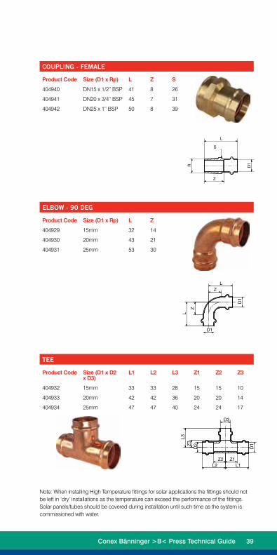
COUPLING - FEMALE
Product Code Size (D1 x Rp) L Z S
404940 DN15 x 1/2” BSP 41 8 26
404941 DN20 x 3/4” BSP 45 7 31
404942 DN25 x 1” BSP 50 8 39
ELBOW - 90 DEG
Product Code Size (D1 x Rp) L Z
404929 15mm 32 14
404930 20mm 43 21
404931 25mm 53 30
TEE
Product Code Size (D1 x D2 x D3)
L1 L2 L3 Z1 Z2 Z3
404932 15mm 33 33 28 15 15 10
404933 20mm 42 42 36 20 20 14
404934 25mm 47 47 40 24 24 17
L
L
Z
Z
D1
D1
D2
D3
D1
L2 L1Z2 Z1
L3Z
3
D1R
L
Z
S
Note: When installing High Temperature fittings for solar applications the fittings should not be left in ‘dry’ installations as the temperature can exceed the performance of the fittings. Solar panels/tubes should be covered during installation until such time as the system is commissioned with water.
Conex Bänninger >B< Press Technical Guide 39

XL Fittings65-100mm

Product Features>B< Press XL has only two internal parts, the grip ring and the seal. Both parts have an internal diameter larger than the tube, which allows for easy tube insertion and pre press leak indication.
Stainless Steel Grip Ring
Complete diameter grip with equally spaced collapse zones ensures all round equal grip on the tube diameter and even seal compression between tube and fitting after pressing.
Conex XL 65, 80 and 100mm copper fittings
EPDM seal
Conex XL fitting
Fitting bead
Copper tubing
Stainless steel grip ring
42 Conex Bänninger >B< Press Technical Guide

Unique Seal Design
The seal is not easily displaced by tube insertion. Triple point seal on the post pressed fitting body counters any pressing distortion. Greater seal contact area on tube. Self setting seal area for correct function of seal. Seal security and longevity increased as a result.
The stainless steel grip rings pressed on top, forcing the grip ring teeth against the tube, making a high strength connection.
Conex Bänninger >B< Press Technical Guide 43

Installation InstructionsTo install >B< Press, a Rothenberger Romax 3000 mechanical tool with actuator and compatible sized jaw to fit each size fitting is required. When pressure is exerted through the press tool a permanent joint is made and the fitting cannot be disassembled or re-used.
1. Cut the pipe
We recommend you use a Rothenberger pipe cutter. It is important to ensure that the pipe is cut completely square. Tube ends should be clean and free from scratches not less than the socket length.
2. Remove burrsMake sure that the internal and external tube end is free from burrs or sharp edges by using a file or deburring tool. Then wipe the tube end clean to avoid damaging the seal on tube insertion.
3. Inspect the fittingKeep fittings in original wrapping until required. Make sure the fitting is protected against dirt and contamination before use. Make sure the fitting and the bag are marked up for the correct application (Water or Gas). Select the correct size fittings for the tube. Before inserting the tube check seal and grip ring for correct placement.
ImportantIt is important to keep the fitting free of any dust or dirt and to ensure the seal stays lubricated and protected from damage. Select the correct size of tube and fitting for the job. Ensure that both are clean and free from damage and imperfections.
44 Conex Bänninger >B< Press Technical Guide

5. Fit the pressing ringUsing the appropriate size pressing ring, open the pressing ring, locate on the fitting bead and close the pressing ring.
6. Engage the actuator and check insertion depth
With the actuator fitted in the press tool open the actuator and locate the actuator into the aperture of the pressing ring. Check for any tube movement prior to pressing.
7. Press the jointDepress and hold the trigger of the tool until the press cycle of the tool is automatically completed. Keep hands clear of the press actuator and press ring until the cycle is completed.
8. Joint completionRemove the actuator from the press ring, remove the press ring from the tube and remove the label to indicate the joint is pressed and complete.
4. Insert the tubeThe tube must be fully inserted into the fitting until it reaches the tube stop in order to make a perfect joint. Marking insertion depth will ensure that any tube movement is detected, which is especially important if the joints are to be pressed at a later time. The depth marking must be visible on the pressed fitting.
Tube Size Insertion DepthDN65 43 mmDN80 50 mmDN100 60 mm
Conex Bänninger >B< Press Technical Guide 45

>B< Press Water
STRAIGHT CONNECTOR
Product Code Size (D1) L Z
404793 DN65 92 4
404794 DN80 106 4
404795 DN100 126 4
REPAIR COUPLING
Product Code Size (D1) L
405121 DN65 110
405122 DN80 125
405123 DN100 144
Range
Z
L
D1
D1
L
D1
D1
46 Conex Bänninger >B< Press Technical Guide

L
D1
D2
Z
COUPLING - REDUCER
Product Code Size (D1 x D2) L1 Z
404822 DN65 x DN32 101 30
404823 DN65 x DN40 100 25
404824 DN65 x DN50 100 24
404825 DN80 x DN40 117 40
404826 DN80 x DN50 119 36
404827 DN80 x DN65 119 25
404828 DN100 x DN50 142 43
404829 DN100 x DN65 134 31
404830 DN100 x DN80 135 25
FITTING REDUCER
Product Code Size (D1 x D2) L Z
404831 DN65 x DN40 106 75
404832 DN65 x DN50 103 64
404833 DN80 x DN50 122 83
404834 DN80 x DN65 131 87
404835 DN100 x DN50 145 106
404836 DN100 x DN65 139 96
404837 DN100 x DN80 136 86
L
D2D1
Z
Conex Bänninger >B< Press Technical Guide 47

COUPLING - MALE
Product Code Size (D1 x R) L Z S
404943 DN65 x 2-1/2 121 78 85
404944 DN80 x 3 126 78 95
404945 DN100 x 4 150 91 125
COUPLING - FEMALE
Product Code Size (D1 x Rp) L Z S
404946 DN65 x 2-1/2 112 31 85
404947 DN80 x 3 114 33 95
404948 DN100 x 4 138 37 125
L
R D1
S (oct)
Z
D1
Rp
L
S (oct)
Z
Range
48 Conex Bänninger >B< Press Technical Guide

ELBOW - 90 DEG
Product Code Size (D1 x D2) L Z
404796 DN65 x DN65 126 82
404797 DN80 x DN80 150 98
404798 DN100 x DN100 192 132
ELBOW - 90 DEG (MALE / FEMALE)
Product Code Size (D1) L Z L2
404857 DN65 x DN65 132 88 146
404858 DN80 x DN80 150 98 148
404859 DN100 x DN100 192 132 212
Z
L
D1
D1
L
Z
L 1
D1
Z
L2
D1
Conex Bänninger >B< Press Technical Guide 49
Range
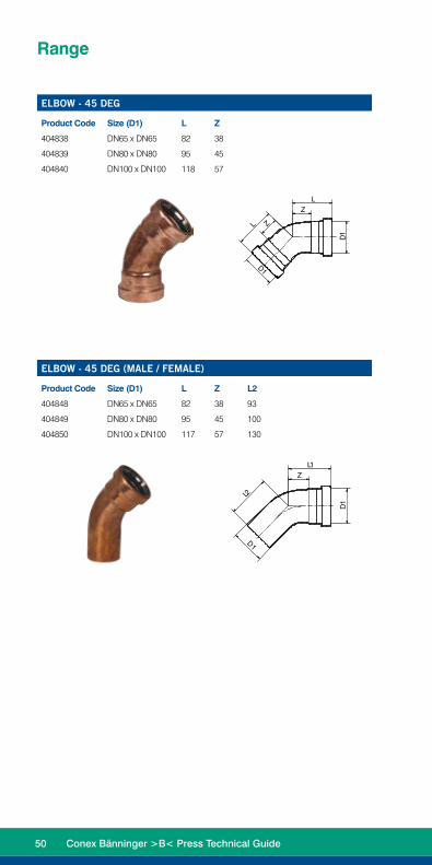
ELBOW - 45 DEG
Product Code Size (D1) L Z
404838 DN65 x DN65 82 38
404839 DN80 x DN80 95 45
404840 DN100 x DN100 118 57
ELBOW - 45 DEG (MALE / FEMALE)
Product Code Size (D1) L Z L2
404848 DN65 x DN65 82 38 93
404849 DN80 x DN80 95 45 100
404850 DN100 x DN100 117 57 130
L1Z
L2
D1
D1
D1
D1
L
L
Z
Z
50 Conex Bänninger >B< Press Technical Guide

L 1
D1
L 2Z 2 Z 1
D2
D3
L3
Z3
TEE
Product Code Size (D1 x D2 x D3) L1 L2 L3 Z1 Z2 Z3
404799 DN65 89 89 104 45 45 46
404800 DN80 101 101 111 50 50 52
404801 DN100 128 128 135 67 67 67
REDUCING TEE
Product Code Size (D1 x D2 x D3) L1 L2 L3 Z1 Z2 Z3
404802 DN65 x DN65 x DN50
84 84 90 40 40 44
404803 DN80 x DN80 x DN50
90 90 96 39 39 50
404804 DN80 x DN80 x DN65
93 93 108 42 42 52
404805 DN100 x DN100 x DN50
105 105 108 44 44 63
404806 DN100 x DN100 x DN65
105 105 123 44 44 66
404807 DN100 x DN100 x DN80
112 112 124 51 51 66
L3
Z3
L 1Z 1
L 2Z 2
D1
D2
D3
Conex Bänninger >B< Press Technical Guide 51

Range
END CAP
Product Code Size (D1) L Z Rp
404841 DN65 86 21 3/4
404842 DN80 98 28 3/4
404843 DN100 115 39 3/4
L
D1
RpZ
52 Conex Bänninger >B< Press Technical Guide

Range
>B< Press Gas
STRAIGHT CONNECTOR
Product Code Size (D1) L Z
404867 DN65 92 4
404868 DN80 106 4
404869 DN100 126 4
REPAIR COUPLING
Product Code Size (D1) L
405130 DN65 110
405131 DN80 125
405132 DN100 144D
1
L
D1
L
ZS
Conex Bänninger >B< Press Technical Guide 53

L
Z
D2
D1
COUPLING - REDUCER
Product Code Size (D1 x D2) L1 Z
404888 DN65 x DN32 101 30
404889 DN65 x DN40 100 25
404890 DN65 x DN50 100 24
404891 DN80 x DN40 117 40
404892 DN80 x DN50 119 36
404893 DN80 x DN65 119 25
404894 DN100 x DN50 142 49
404895 DN100 x DN65 134 31
404896 DN100 x DN80 135 25
FITTING REDUCER
Product Code Size (D1 x D2) L Z
404897 DN65 x DN40 106 75
404898 DN65 x DN50 103 66
404899 DN80 x DN50 122 89
404900 DN80 x DN65 131 87
404901 DN100 x DN50 145 112
404902 DN100 x DN65 139 96
404903 DN100 x DN80 136 86
D2
D1
Z
L
Range
54 Conex Bänninger >B< Press Technical Guide

COUPLING - MALE
Product Code Size (D1 x R) L Z S
405124 DN65 x 2-1/2 121 78 85
405125 DN80 x 3 126 78 95
405126 DN100 x 4 150 91 125
COUPLING - FEMALE
Product Code Size (D1 x Rp) L Z S
405127 DN65 x 2-1/2 112 31 85
405128 DN80 x 3 114 33 95
405129 DN100 x 4 138 37 125
L
Z
D1
R
S (oct)
L
Z
S (oct)
D1
Rp
Conex Bänninger >B< Press Technical Guide 55

ELBOW - 90 DEG
Product Code Size (D1 x D2) L Z
404870 DN65 x DN65 126 82
404871 DN80 x DN80 150 98
404872 DN100 x DN100 192 132
ELBOW - 90 DEG (MALE / FEMALE)
Product Code Size (D1) L Z L2
404923 DN65 x DN65 132 88 146
404924 DN80 x DN80 150 98 148
404925 DN100 x DN100 192 132 212
L
Z
S
D1
D1
L1
L2
Z
Range
56 Conex Bänninger >B< Press Technical Guide

ELBOW - 45 DEG
Product Code Size (D1) L Z
404914 DN65 x DN65 82 38
404915 DN80 x DN80 95 45
404916 DN100 x DN100 118 57
ELBOW - 45 DEG (MALE / FEMALE)
Product Code Size (D1) L Z L2
404904 DN65 x DN65 82 38 93
404905 DN80 x DN80 95 45 100
404906 DN100 x DN100 117 57 130
D1
D1
L1
L2Z
D1
D1
L
L
Z
Z
Conex Bänninger >B< Press Technical Guide 57

L3
Z3
D2
D1
D3
Z2L2 L1
Z1
TEE
Product Code Size (D1 x D2 x D3) L1 L2 L3 Z1 Z2 Z3
404873 DN65 89 89 104 45 45 46
404874 DN80 101 101 111 50 50 52
404875 DN100 128 128 135 67 67 67
REDUCING TEE
Product Code Size (D1 x D2 x D3) L1 L2 L3 Z1 Z2 Z3
404876 DN65 x DN65 x DN50
84 84 90 40 40 44
404877 DN80 x DN80 x DN50
90 90 96 39 39 50
404878 DN80 x DN80 x DN65
90 90 96 39 39 50
404879 DN100 x DN100 x DN50
105 105 108 44 44 63
404880 DN100 x DN100 x DN65
105 105 123 44 44 66
404881 DN100 x DN100 x DN80
112 112 124 51 51 66
D1
D3L3
Z3
D2
Z2 L1Z1Z2
Range
END CAP
Product Code Size (D1) L Z Rp
404907 DN65 86 21 1/2
404908 DN80 98 28 1/2
404909 DN100 115 39 1/2
D1
L
Z
Rp
58 Conex Bänninger >B< Press Technical Guide

Installation Requirements
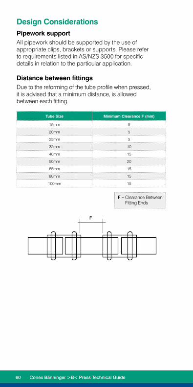
Design ConsiderationsPipework supportAll pipework should be supported by the use of appropriate clips, brackets or supports. Please refer to requirements listed in AS/NZS 3500 for specific details in relation to the particular application.
Distance between fittingsDue to the reforming of the tube profile when pressed, it is advised that a minimum distance, is allowed between each fitting.
Tube Size Minimum Clearance F (mm)
15mm 5
20mm 5
25mm 5
32mm 10
40mm 15
50mm 20
65mm 15
80mm 15
100mm 15
F
F – Clearance Between Fitting Ends
60 Conex Bänninger >B< Press Technical Guide
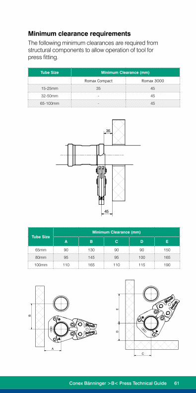
Minimum clearance requirements The following minimum clearances are required from structural components to allow operation of tool for press fitting.
Tube Size Minimum Clearance (mm)
Romax Compact Romax 3000
15-25mm 35 45
32-50mm - 45
65-100mm - 45
1
1
2
2
3
3
4
4
5
5
6
6
A A
B B
C C
D D
Index Änderungsauftrag Datum Name
Datum Name
Bearbeitet
Geprüft
Genehmigt
Tolerierung ISO8015
Änderungen nur über CADWeitergabe sowie Vervielfältigung dieses Dokuments, Verwertung und Mitteilung seines Inhalts sind verboten, soweit nicht ausdrücklich gestattet. Zuwiderhandlungen verpflichten zu Schadenersatz. Alle Rechte für den Fall der Patent- , Gebrauchsmuster- oder Geschmacksmustereintragung vorbehalten.
Allg.-Toleranzen
ISO 2768 mK
OberflächenDIN EN
ISO 1302
Maßstab : Gewicht [ kg ] :
Werkstoff :
Benennung :
Sach-Nr.: Blatt :
von :
Ersatz für : Ersetzt durch :Ursprung :CAD-Nr.:
45938Y02
Einbauräume PSL V8017.10.2013 Rafalski
1 1 \\Npfile10\kdaten\45000\45938\45938Y02
Einbauraum V80.idw
DIN
Halbzeug :
A3
B
A
D
C
E
35
45 1
1
2
2
3
3
4
4
5
5
6
6
A A
B B
C C
D D
Index Änderungsauftrag Datum Name
Datum Name
Bearbeitet
Geprüft
Genehmigt
Tolerierung ISO8015
Änderungen nur über CADWeitergabe sowie Vervielfältigung dieses Dokuments, Verwertung und Mitteilung seines Inhalts sind verboten, soweit nicht ausdrücklich gestattet. Zuwiderhandlungen verpflichten zu Schadenersatz. Alle Rechte für den Fall der Patent- , Gebrauchsmuster- oder Geschmacksmustereintragung vorbehalten.
Allg.-Toleranzen
ISO 2768 mK
OberflächenDIN EN
ISO 1302
Maßstab : Gewicht [ kg ] :
Werkstoff :
Benennung :
Sach-Nr.: Blatt :
von :
Ersatz für : Ersetzt durch :Ursprung :CAD-Nr.:
45938Y02
Einbauräume PSL V8017.10.2013 Rafalski
1 1 \\Npfile10\kdaten\45000\45938\45938Y02
Einbauraum V80.idw
DIN
Halbzeug :
A3
B
A
D
C
E
35
45
1
1
2
2
3
3
4
4
5
5
6
6
A A
B B
C C
D D
Index Änderungsauftrag Datum Name
Datum Name
Bearbeitet
Geprüft
Genehmigt
Tolerierung ISO8015
Änderungen nur über CADWeitergabe sowie Vervielfältigung dieses Dokuments, Verwertung und Mitteilung seines Inhalts sind verboten, soweit nicht ausdrücklich gestattet. Zuwiderhandlungen verpflichten zu Schadenersatz. Alle Rechte für den Fall der Patent- , Gebrauchsmuster- oder Geschmacksmustereintragung vorbehalten.
Allg.-Toleranzen
ISO 2768 mK
OberflächenDIN EN
ISO 1302
Maßstab : Gewicht [ kg ] :
Werkstoff :
Benennung :
Sach-Nr.: Blatt :
von :
Ersatz für : Ersetzt durch :Ursprung :CAD-Nr.:
45938Y02
Einbauräume PSL V8017.10.2013 Rafalski
1 1 \\Npfile10\kdaten\45000\45938\45938Y02
Einbauraum V80.idw
DIN
Halbzeug :
A3
B
A
D
C
E
35
45
Tube Size Minimum Clearance (mm)
A B C D E
65mm 90 130 90 90 150
80mm 95 145 95 100 165
100mm 110 165 110 115 190
Conex Bänninger >B< Press Technical Guide 61
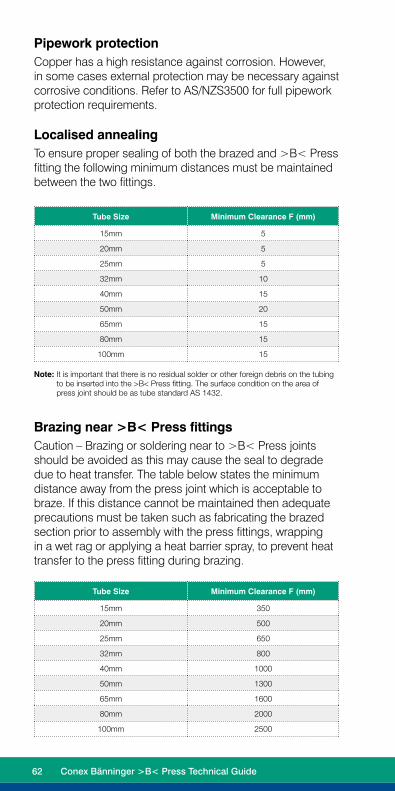
Pipework protectionCopper has a high resistance against corrosion. However, in some cases external protection may be necessary against corrosive conditions. Refer to AS/NZS3500 for full pipework protection requirements.
Localised annealingTo ensure proper sealing of both the brazed and >B< Press fitting the following minimum distances must be maintained between the two fittings.
Tube Size Minimum Clearance F (mm)
15mm 5
20mm 5
25mm 5
32mm 10
40mm 15
50mm 20
65mm 15
80mm 15
100mm 15
Note: It is important that there is no residual solder or other foreign debris on the tubing to be inserted into the >B< Press fitting. The surface condition on the area of press joint should be as tube standard AS 1432.
Brazing near >B< Press fittingsCaution – Brazing or soldering near to >B< Press joints should be avoided as this may cause the seal to degrade due to heat transfer. The table below states the minimum distance away from the press joint which is acceptable to braze. If this distance cannot be maintained then adequate precautions must be taken such as fabricating the brazed section prior to assembly with the press fittings, wrapping in a wet rag or applying a heat barrier spray, to prevent heat transfer to the press fitting during brazing.
Tube Size Minimum Clearance F (mm)
15mm 350
20mm 500
25mm 650
32mm 800
40mm 1000
50mm 1300
65mm 1600
80mm 2000
100mm 2500
62 Conex Bänninger >B< Press Technical Guide

Flushing of water installationsWhen the installation is complete, it is essential to flush with water to remove dust and debris in accordance with AS/NZS 3500.
Testing and commissioning installationsThe unique pressing indicator is a specially designed O-ring. It has a reduced section in two positions that allows water or air past the sealing element of any unpressed connection, thereby providing a visible leakage point during the commissioning of the system. Unpressed fittings are identified by pressurizing the system with a pressure range of 100 kPa to 500 kPa for water and 2.2 kPa to 300 kPa for gas. When the fitting is pressed, the O-ring material compresses, filling the gaps, creating a leak free joint. Final testing of the system should be conducted in accordance with AS/NZS 3500 and/or AS/NZS 5601.
Earth continuity >B< Press fittings maintain earth continuity without the need for additional continuity straps.
Connection to other materialsWhen connecting to other materials with the use of a >B< Press threaded adaptor it is recommend that threaded connections be installed first, prior the fitting being pressed. When tightening the adaptor ensure that the wrenching flats are used, not the tube section of the fitting.
Fittings in freezing temperatures Copper tube and press fittings should be protected against freezing. Expansion of the water when it freezes can cause damage to the pipe or fitting.
Conex Bänninger >B< Press Technical Guide 63


The ToolsThe following tools are the only tools approved for use on Conex Bänninger >B< Press fittings:
• Romax compact (Rothenberger)
• Romax 3000 (Rothenberger)
• Picco (Viega)
• PT3-AH & 4B (Viega)

Tools 15-50mm
Conex Bänninger recommends the use of Rothenberger press tools.
RomaxCompact model
Applications sizes: 15-25mm >B< Press Fittings
• Compact light weight design – one hand operation.
• CFT® - Technology for constant axial 19kN shearing force.
• Safety latch to ensure jaw cannot come out during operation.
• Easy to use LED status indication – flashing red when battery charge is low and will lock the machine, remains ON when tool has reached 10,000 cycles of use and requires servicing.
• Simple & safe operation design – hold start button – tool automatically stops once press cycle is complete.
• Safety yellow button – press to release pressure and stop press cycle.
• Convenient 10,000 cycle interval between service requirements.
• Head positioning up to 270° rotation – easy fitting in difficult locations.
• Li-Ion battery technology – long lasting operation between charges.
Battery voltage – 14.4 v
Battery Capacity – 2.6Ah
Rated power consumption – 280Watts
Max piston force – 19kN
Pressing time – 5 secs (nominal)
Dimensions (L x W x H) – 380 x 70 x 90mm
Weight (less jaws) – 2.45 kg
Working range: Copper system 12 – 28mm Plastic system 12 – 40mm
Typical A-rate noise level – 71dB(A)
Battery re-charge time periods – 87 minutes
Approximate pressings per full charge – 140
Specifications
66 Conex Bänninger >B< Press Technical Guide

Conex Bänninger recommends the use of Rothenberger press tools.
Romax3000 model
Applications sizes: 15-50mm >B< Press Fittings
• Weight balanced ergonomic design – reduces fatigue during extended use.
• Wide application range.
• Fast pressing – automatic cycle complete in 5 seconds.
• Easy to use LED status indication – flashing red when battery charge is low and will lock the machine, remains ON when tool has reached 20,000 cycles of use and requires servicing.
• Bright white - light LED’s to illuminate work space during pressing cycle.
• Simple & safe operation design – hold start button – tool automatically stops once press cycle is complete.
• Safety yellow button – press to release pressure and stop press cycle.
• Long 20,000 cycle interval between service requirements.
• Head positioning up to 270° rotation – easy fitting in difficult locations.
• Li-Ion battery technology – long lasting operation between charges.
SpecificationsBattery voltage – 18 v
Battery Capacity – 3Ah
Rated power consumption – 540 Watts
Max piston force – 32kN
Pressing time – 5 secs (nominal)
Dimensions (LxWxH) – 445x125x79mm
Weight (less jaws) – 3.54 kg
Working range: Copper system 12 – 108mm
Typical A-rate noise level – 71dB(A)
Battery re-charge time periods – 85 minutes (90% charge) – 2.5hrs (100% charge)
Approximate pressings per full charge – 160
Conex Bänninger >B< Press Technical Guide 67

Tools XL 65-100mmThe approved tools for the installation of >B< Press XL fittings are:• Rothenberger Romax® 3000• Viega Picco 4B
Conex Bänninger recommends the use of Rothenberger press tools.
Rothenberger Romax®
3000 model
Applications sizes: 15-100mm >B< Press Fittings
• Weight balanced ergonomic design – reduces fatigue during extended use
• Wide application range
• Fast pressing – automatic cycle complete in 5 seconds
• Easy to use LED status indication – flashing red when battery charge is low and will lock the machine, remains ON when tool has reached 20,000 cycles of use and requires servicing
• Bright white - light LED’s to illuminate work space during pressing cycle
• Simple and safe operation design – hold start button – tool automatically stops once press cycle is complete
• Safety yellow button – press to release pressure and stop press cycle
• Long 20,000 cycle interval between service requirements
• Head positioning up to 270° rotation – easy fitting in difficult locations
• Li-Ion battery technology – long lasting operation between charges
SpecificationsBattery voltage – 18 v
Battery capacity – 3Ah
Rated power consumption – 540 Watts
Max piston force – 32kN
Pressing time – 5 secs (nominal)
Dimensions (LxWxH) – 445x125x79mm
Weight (less jaws) – 3.54 kg
Working range: Copper system 15 – 100mm
Typical A-rate noise level – 71dB(A)
Battery re-charge time periods – 85 minutes (90% charge) – 2.5hrs (100% charge)
Approximate pressings per full charge – 160
68 Conex Bänninger >B< Press Technical Guide

Rothenberger XL Press Jaws & ActuatorFor Romax® Press Tools
To press >B< Press XL fittings an actuator and appropriately sized jaw are required.
To complete a press the jaw is opened and located on the fitting bead. The actuator is connected to the tool, ensuring the locking pin is fully engaged. With the actuator fitted in the press tool open the actuator and locate the actuator into the aperture of the pressing ring. To perform the press hold the trigger of the tool until the press cycle of the tool is automatically completed.
XL Press Jaws For Romax® Press Tools
• Made of forged, highly resilient special steel
• Compact design
• Long-term corrosion protection
• Optimised for minimal space requirements
ActuatorFor Romax® Press Tools
• Precision-manufactured contours for optimum and reliable pressings
• Made of forged, highly resilient special steel
• Long-term corrosion protection
Conex Bänninger >B< Press Technical Guide 69

Critical Operating Instructions - Tool & Jaw
Only operate the Rothenberger Press Tool and Jaws as per instructions in your ‘User Operating Manual, Instructions for Use’. Proper usage includes compliance with the operating manual, inspection and servicing conditions and adherence to all relevant safety regulations. The equipment must only be used by qualified tradespersons that have a trained understanding on how to use the Press Tool & Jaw System properly. Failure to do so will lead to safety risk, poor workmanship, and incorrect use of the Press & Jaw that is not covered under warranty. Only use Rothenberger Press Tools & Jaws with compatible Press Fittings that have been tested and approved by Rothenberger and associated Fitting & Pipe manufacturers (>B< Press, Auspex, Duopex).
• Always start with a safety check, reminding yourself of the yellow emergency stop button to deactivate a press cycle
• Charge battery fully before first use for optimal number of ‘presses per charge’
• LED flashes red to indicate when you have a flat battery
• Insert battery correctly until it clicks into place and LED light flashes briefly to indicate contact made
• Insert Press Jaw & close bolt down correctly. Only use the correct Jaw to Tool to Fitting combination
• Open the Jaw by squeezing from the base of the Jaw NOT the front tip (it can crush your fingers!)
• Half engage the start button for the handy LED lights (only on the larger Romax 3000 tool)
• Fully engage the start button for a full press cycle. Activate the Press Tool & Jaw only on a fitting
• Take the time to ensure the correct pipe preparation – cut pipe square, debur & calibrate pipe edge & mark insertion depth. These pipe prep steps are critical for a correct press and quality workmanship
• Follow all installation instructions supplied by the fitting & pipe manufacturers. Imperfect pipe joints must only be pressed again using a new fitting, DO NOT re-press the same fitting
• During the press cycle, visually check that the Press Jaw fully closes at the end of the press cycle
• After pressing, check the installation with appropriate testing equipment and ensure it is leak proof
70 Conex Bänninger >B< Press Technical Guide

Regular Maintenance Instructions - Tool & Jaw
Tool – Always clean & grease and store in case
Your Rothenberger Tool is one of the lightest and most ergonomic designed tools that delivers the most consistent press force (CFT® - Constant Force Technology) with regular maintenance and service it generates up to 3.2 tonnes of force in your hand, so it requires regular care & maintenance
• Clean & grease the piston ram & drive rolls ALWAYS after every use to maintain performance especially the internal guide rail OR all the ‘moving metallic parts’
• Watch heavy water areas. Do not expose power tools to rain or wet conditions. Always store in case
• Ensure the Jaw locking bolt is closed correctly by fully inserting the bolt through the Jaw and rotating the bolt arm down 180 degrees
• Please note, the bolt is only secured when fully inserted and rotated into the downward position
Conex Bänninger >B< Press Technical Guide 71
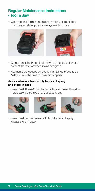
Regular Maintenance Instructions - Tool & Jaw
• Clean contact points on battery and only store battery in a charged state, plus it’s always ready for use
•
• Do not force the Press Tool – it will do the job better and safer at the rate for which it was designed
• Accidents are caused by poorly maintained Press Tools & Jaws. Take the time to maintain properly
Jaws – Always clean, apply lubricant spray and store in case
• Jaws must ALWAYS be cleaned after every use. Keep the inside Jaw profile free of any grease & grit
• Jaws must be maintained with liquid lubricant spray. Always store in case
72 Conex Bänninger >B< Press Technical Guide

Servicing & Warranty - Tool & Jaw
Rothenberger prides itself on leading edge design, the highest quality, and leading after-sale service support. With ownership of your Rothenberger Tool comes our commitment to support you. We want to help you ‘look after your tool’, so you don’t compromise your reputation. Only have your Press & Jaws inspected and serviced by a qualified Rothenberger Service Centre for high performance & safety.
• Quick Fix™ is the Rothenberger ‘After Sales & Service’ repair process across Australia & New Zealand
• Comprehensive spare parts are readily available locally to support your Rothenberger Tool & Jaws
• Jaws will also be checked at the annual service interval for any damage, defects and general wear & tear that could affect the press performance or safety
Warranty Coverage• After 1 year or 10,000 (Compact) 20,000 (Romax 3000)
presses the LED lights up red after each press
• A press cycle count will be made as part of your annual Tool & Jaw servicing & report
• If a serial number sticker is damaged the warranty will be null & void
• The warranty does not cover damage caused by incorrect use of the equipment
• Tool 3 years, only with regular 1 year or cycle count servicing (like servicing your car!)
• Battery 12 months, Jaws 12 months
Service & Warranty Process – Quick Fix™• Return your Rothenberger Press Tool & Jaw Set to your
local Branch or call Rothenberger Customer Service (Toll Free) on 1800 186 657
• Your details and serial number of your tool will be logged for a service and pick up quickly arranged
• Expect 3-5 days (parts dependant) for your service and tools returned to you, or your local branch
• Live status updates will be emailed & sent via text message to you and your local branch
• Any additional repair work beyond the normal annual service will be quoted prior to commencement
Conex Bänninger >B< Press Technical Guide 73

Frequently Asked Questions
74 Conex Bänninger >B< Press Technical Guide

Fittings Frequently Asked Questions
Q. How long has Conex Bänninger been around? A. Since 1909.
Q. Where are the products manufactured? A. Europe.
Q. What grades of copper tube do the fittings suit? A. Annealed, half hard and hard drawn type A and B
plumbing tube to AS1432.
Q. Can you rotate a >B< Press fitting once installed? A. No, once pressed, they cannot be rotated.
Q. Can >B< Press be dismantled and reused? A. No, this is a permanent installation.
Q. Can the O-rings from water and gas fittings be swapped? A. No. The O-ring is integral to the seal of the fitting,
swapping the O-ring increases the risk of damage and therefore O-rings are not to be interchanged.
Q. What pipe preparation is required? A. Please see ‘Installation guidelines’ on pages18-19
and for XL fittings pages 44-45.
Q. When using with older pipes, how do you prepare the surface?
A. The surface should be prepared in the same way as with new pipe. And provided there is no corrosion, the tube dimensions comply with AS 1432 (type A & B) and the fittings are installed correctly, there are no warranty issues. Note: Warranty is limited to faults due to the manufacturing defects of the fittings – not incorrect installation or installation on faulty or corroded pipe.
Q. What are the application limitations, where can’t it be used?
A. It cannot be used where pressures are greater than those recommended or where corrosive fluids/gases need to be transmitted.
Conex Bänninger >B< Press Technical Guide 75

Fittings Frequently Asked Questions
Q. What pressure do you need to test to and for how long to show any leaks?
A. Unpressed fittings are identified by pressurising the system with a pressure range of 100 kPa to 500 kPa for water and 2.2 kPa to 300 kPa for gas. Final testing of the system should be conducted in accordance with AS/NZS 3500 and/or AS/NZS 5601.
Q. Can it be used with medical gas? A. No, the fittings are not recommended for use with
medical gas.
Q. Can it be exposed to direct sunlight and heat? A. Yes – please see table on pages 10-13 for limitations
due to pressure and temperature.
Q. Am I able to use a Viega tool to crimp the >B< Press fitting?
A. Yes, the approved tools for installation of >B< Press fittings are: Romax compact (Rothenberger), Romax 3000 (Rothenberger), Picco (Viega), PT3-AH & 4B (Viega).
Q. Does the clipping of fittings/jobs differ from a welded copper application?
A. No, the same type of clips can be used. See ‘pipework support’ on page 60.
Q. Can it be placed in ground with all types of soils?A. Yes but please refer to ‘pipework protection’
on page 62.
Q. Can the fittings be used for solar installations?
A. >B< Press water fittings are not recommended for solar installations. >B< Press HT fittings are recommended for these installations.
Q. What is the recommended space between fittings?
A. Please see ‘distance between fittings’ section on pages 60.
76 Conex Bänninger >B< Press Technical Guide

Fittings Frequently Asked Questions
Q. Can the fittings be used on compressed air or oil lines?A. >B< Press water fittings are recommended for
compressed air (oil free) and >B< Press Gas fittings are suitable for all compressed air applications.
Q. What are benefits >B< Press fittings? A. Fast, simple and reliable installation.
Q. Are there any restrictions in regards to where flanges can be used?
A. Providing the selection of the sealing gasket considers the same system parameters and application, flanges may be used in all situations that other >B< Press fittings cater for.
Q. Can you braze (silver soldering) near a >B< Press connection?
A. See section on brazing near >B< Press fittings on page 62.
Q. Can >B< Press handle suction or negative pressure? A. Yes, >B< Press fittings are tested at a vacuum test
pressure of - 80 kPa at ambient temperature.
Q. Can >B< Press be installed on pipes where the mains line won’t shut off.
A. Yes, the fitting can be used in wet conditions and after pressing will provide a watertight joint.
Q. Do I need to lubricate the O-ring?A. No, the O-ring is prelubricated. Additional lubricants
could impact on the life of the O-ring and void the warranty. If the O-ring appears dry a small amount of water can be used to lubricate it.
Q. Can >B< Press fittings be used on chrome tube?A. Yes, provided that the tube complies with AS 1432.
However it is recommended to test a piece first as some splitting of the chrome may occur.
Conex Bänninger >B< Press Technical Guide 77

For more information visitwww.reece.com.au/bpress
Call 1800 032 566 or visit www.reece.com.au for your nearest Reece store.
The manufacturer/distributor reserves the right to vary specifications or delete models from their range without prior notification. The manufacturer/distributor takes no responsibility for printing errors. All measurement and content details in this brochure are subject to a tolerance of ± 3 %. V1 [BROCHURE CODE 2130196]
Reece. Works for you.™