b hvac&r research - college of engineering - purdue · pdf file ·...
TRANSCRIPT
This article was downloaded by: [University of Illinois at Urbana-Champaign]On: 02 April 2013, At: 13:17Publisher: Taylor & FrancisInforma Ltd Registered in England and Wales Registered Number: 1072954 Registeredoffice: Mortimer House, 37-41 Mortimer Street, London W1T 3JH, UK
HVAC&R ResearchPublication details, including instructions for authors andsubscription information:http://www.tandfonline.com/loi/uhvc20
Dynamic modeling of refrigeratedtransport systems with cooling-mode/heating-mode switch operationsBin Li a , Neera Jain a , William F. Mohs b , Scott Munns c , VikasPatnaik c , Jeff Berge b & Andrew G. Alleyne aa Department of Mechanical Science and Engineering, Universityof Illinois at Urbana-Champaign, MC-244, 1206 West Green Street,Urbana, IL, 61801, USAb Department of R&D Engineering, Climate Control Technologies,Ingersoll Rand, Minneapolis, MN, USAc Global Modeling & Analysis, Climate Solutions, Ingersoll Rand, LaCrosse, WI, USAVersion of record first published: 27 Sep 2012.
To cite this article: Bin Li , Neera Jain , William F. Mohs , Scott Munns , Vikas Patnaik , Jeff Berge &Andrew G. Alleyne (2012): Dynamic modeling of refrigerated transport systems with cooling-mode/heating-mode switch operations, HVAC&R Research, 18:5, 974-996
To link to this article: http://dx.doi.org/10.1080/10789669.2012.670685
PLEASE SCROLL DOWN FOR ARTICLE
Full terms and conditions of use: http://www.tandfonline.com/page/terms-and-conditions
This article may be used for research, teaching, and private study purposes. Anysubstantial or systematic reproduction, redistribution, reselling, loan, sub-licensing,systematic supply, or distribution in any form to anyone is expressly forbidden.
The publisher does not give any warranty express or implied or make any representationthat the contents will be complete or accurate or up to date. The accuracy of anyinstructions, formulae, and drug doses should be independently verified with primarysources. The publisher shall not be liable for any loss, actions, claims, proceedings,demand, or costs or damages whatsoever or howsoever caused arising directly orindirectly in connection with or arising out of the use of this material.
Dynamic modeling of refrigerated transport systems withcooling-mode/heating-mode switch operations
Bin Li,1 Neera Jain,1 William F. Mohs,2 Scott Munns,3 Vikas Patnaik,3
Jeff Berge,2 and Andrew G. Alleyne1,∗1Department of Mechanical Science and Engineering, University of Illinois at Urbana-Champaign, MC-244, 1206
West Green Street, Urbana, IL 61801, USA2Department of R&D Engineering, Climate Control Technologies, Ingersoll Rand, Minneapolis, MN, USA
3Global Modeling & Analysis, Climate Solutions, Ingersoll Rand, La Crosse, WI, USA∗Corresponding author e-mail: [email protected]
This article presents dynamic modeling approaches to predict system performance characteristicsof cooling-/heating-mode switch cycling operation, a commonly used temperature regulation approach inrefrigerated transport systems. A dynamic model of a commercially available transport refrigeration systemis presented, which describes the system dynamics during the mode switch transients. The developmentof the heat exchanger and accumulator models is highlighted using the switched modeling framework.Model validation against experimental data demonstrates the capabilities of the modeling approach inrepresenting the transient behavior of the mode switch process. Simulation case studies to predict refrigerantmass distribution during transients and system performance with the influence of door-opening events arealso provided to demonstrate modeling capabilities. The presented dynamic modeling framework can serveas a valuable tool to evaluate performance with different system configurations and operating strategies intransport refrigeration applications.
Introduction
Refrigerated transport systems, such as refriger-ated road vehicles and refrigerated shipping con-tainers, are widely used to distribute chilled andfrozen products throughout the world. As an essen-tial sector in the food supply cold chain, more andmore attention is paid to food transport refrigerationbecause of increasing concerns on food safety andquality, as well as its impact on energy consumptionand the environment (Tassou et al. 2009; Akkerman
Received November 22, 2011; accepted February 9, 2012Bin Li is PhD candidate. Neera Jain, Student Member ASHRAE, is PhD candidate. William F. Mohs, Member ASHRAE, isSenior Engineer. Scott Munns is Senior Engineer. Vikas Patnaik, PhD, Member ASHRAE, is Engineering Manager. Jeff Berge,Member ASHRAE, is R&D Manager. Andrew G. Alleyne, PhD, is Ralph M. and Catherine V. Fisher Professor.
et al. 2010). An important characteristic of these re-frigeration systems is temperature regulation so thatthe quality of perishable foods is preserved and theshelf life is extended during transport (James et al.2006).
To satisfy customer needs for shipping a widerange of cargo under tight temperature control,the transport refrigeration industry has respondedby improving temperature control techniques, pro-viding greater cooling capacity, and offering loadflexibility, for example, from single cargo space to
974
HVAC&R Research, 18(5):974–996, 2012. Copyright C© 2012 ASHRAE.ISSN: 1078-9669 print / 1938-5587 onlineDOI: 10.1080/10789669.2012.670685
Dow
nloa
ded
by [
Uni
vers
ity o
f Il
linoi
s at
Urb
ana-
Cha
mpa
ign]
at 1
3:17
02
Apr
il 20
13

HVAC&R RESEARCH 975
multi-space systems, as noted in Vaclavek et al.(2003). Compared with stationary systems, trans-port refrigeration systems are required to performreliably over a variety of operating conditions,such as broad temperature ranges of transportedfood products and wide variations in climaticconditions. Additionally, the refrigeration systemsneed to be designed to be energy efficient withoutcompromising the temperature control of the prod-ucts. To investigate and improve the refrigerationsystem performance, good knowledge of the systembehavior is required and can be obtained eitherfrom modeling and simulation tools or throughexperimental studies. As mentioned in Koury et al.(2001), the use of well-verified numerical modelscan facilitate the understanding of system dynamicbehavior, serve as a tool to evaluate alternativesystem designs and operating strategies, and mini-mize the time and expense of test-cell experiments.However, considering refrigerated transport isa complex interacting system, complete under-standing of dynamic models to predict the systemthermodynamic behavior is still lacking, and manyefforts have been dedicated to improve predictivecapabilities (James et al. 2006; Jolly et al. 2000).
This present study develops a specific modelingapproach to simulate common operations in re-frigerated transport applications: cooling-/heating-mode switch cycling operations (Tso et al. 2001;Repice and Stumpf 2007). Different from cyclingthe refrigeration systems on and off for temperatureregulation (Li et al. 2010), in cooling-/heating-modeswitch operation, the product temperature is main-tained at a set-point below the ambient conditionsby continuously running the system and cyclingbetween cooling and heating modes. One reasonto drive the refrigeration equipment to switch fromcooling to heating mode is the need for defrostingthe heat exchangers (Hoffenbecker et al. 2005;Dopazo et al. 2010). Another reason is to maintain acontinuous supply of air moving over the transportedfood product, which is a requirement for freshproduce (e.g., strawberries). The cooling-/heating-mode switch allows for temperature regulationwhile maintaining continuous air circulation.
It is challenging to simulate the mode switchcycling operation since it is a complex and highlytransient process involving component functionvariations as well as many indeterminate variables(Krakow et al. 1993). From the open literature inheat pump applications, there have been extensiveexperimental investigations of system performance
during the switch between normal operating modeand defrosting mode. These include reverse-cycledefrosting processes (Miller 1987; O’Neal et al.1989; Qu et al. 2012) and hot-gas bypass defrostingmethods (Cho et al. 2005; Byun et al. 2008). Never-theless, there are few studies on the development ofsimulation models to predict the system dynamicsunder normal-/defrosting-mode switch cyclingoperation. Krakow et al. (1993) developed ananalytical reverse-cycle defrosting model where themelting process on the coil surface was idealizedby subdividing it into different stages. Based on theabove modeling theory, Liu et al. (2003) presenteda validated reverse-cycle defrosting model for anair-source heat pump system. While the defrostprocess is important, this article focuses on thedevelopment of capabilities to simulate the modeswitch cycle operation for temperature regulationin transport refrigeration, rather than detailingthe frost melting mass and heat transfer processinvolved in the defrosting mechanism.
To investigate the dynamic behavior of refriger-ation systems, heat exchangers are usually treatedwith transient models. Two common heat exchangermodeling approaches, finite-volume and moving-boundary methods, have been reported in theliterature (He et al. 1997; Jensen and Tummescheit2002; Bendapudi and Braun 2002; Rasmussenand Alleyne 2004; Bendapudi et al. 2005; Ebornet al. 2005; Limperich et al. 2005). Liu et al.(2003) used distributed-parameter finite-volumemodels for the condenser and evaporator during thedefrosting cycle. Bendapudi et al. (2008) comparedthe two approaches in predicting system start-upand load change transients in a centrifugal chillerapplication, while Kapadia et al. (2009) appliedthe finite-volume approach to analyze the start-upperformance of a split air-conditioning system. Aswitched moving-boundary framework was demon-strated in Li and Alleyne (2010) to simulate systemshut-down and start-up performance. In this frame-work, the heat exchangers were developed withdifferent model representations to accommodate thetransitions of dynamic states during transients. Jain(2009) developed cooling-mode and heating-modeoperation dynamic models for a commercial trans-port refrigeration unit, where the moving-boundarymodeling approach was applied. On the basis ofthe switched modeling framework (Li and Alleyne2010) and the transport refrigeration models (Jain2009), this article models the single cargo spacetransport refrigeration system, validates the system
Dow
nloa
ded
by [
Uni
vers
ity o
f Il
linoi
s at
Urb
ana-
Cha
mpa
ign]
at 1
3:17
02
Apr
il 20
13
976 VOLUME 18, NUMBER 5, OCTOBER 2012
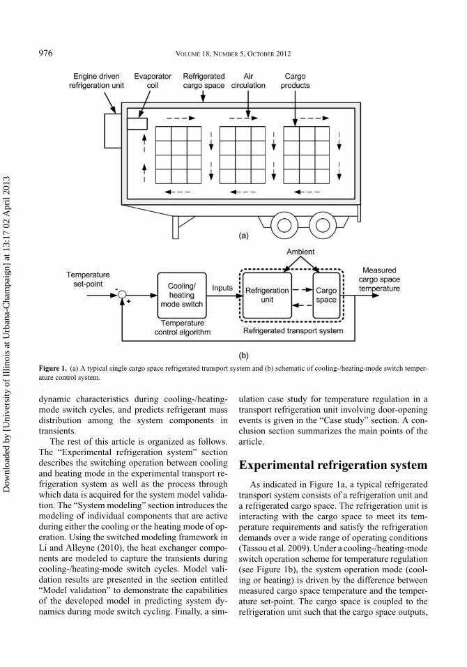
Figure 1. (a) A typical single cargo space refrigerated transport system and (b) schematic of cooling-/heating-mode switch temper-ature control system.
dynamic characteristics during cooling-/heating-mode switch cycles, and predicts refrigerant massdistribution among the system components intransients.
The rest of this article is organized as follows.The “Experimental refrigeration system” sectiondescribes the switching operation between coolingand heating mode in the experimental transport re-frigeration system as well as the process throughwhich data is acquired for the system model valida-tion. The “System modeling” section introduces themodeling of individual components that are activeduring either the cooling or the heating mode of op-eration. Using the switched modeling framework inLi and Alleyne (2010), the heat exchanger compo-nents are modeled to capture the transients duringcooling-/heating-mode switch cycles. Model vali-dation results are presented in the section entitled“Model validation” to demonstrate the capabilitiesof the developed model in predicting system dy-namics during mode switch cycling. Finally, a sim-
ulation case study for temperature regulation in atransport refrigeration unit involving door-openingevents is given in the “Case study” section. A con-clusion section summarizes the main points of thearticle.
Experimental refrigeration system
As indicated in Figure 1a, a typical refrigeratedtransport system consists of a refrigeration unit anda refrigerated cargo space. The refrigeration unit isinteracting with the cargo space to meet its tem-perature requirements and satisfy the refrigerationdemands over a wide range of operating conditions(Tassou et al. 2009). Under a cooling-/heating-modeswitch operation scheme for temperature regulation(see Figure 1b), the system operation mode (cool-ing or heating) is driven by the difference betweenmeasured cargo space temperature and the temper-ature set-point. The cargo space is coupled to therefrigeration unit such that the cargo space outputs,
Dow
nloa
ded
by [
Uni
vers
ity o
f Il
linoi
s at
Urb
ana-
Cha
mpa
ign]
at 1
3:17
02
Apr
il 20
13

HVAC&R RESEARCH 977
e.g., return air temperature (normally considered asthe cargo space temperature), are the inputs to therefrigeration unit, e.g., evaporator air inlet tempera-ture. Simultaneously, the refrigeration unit outputs,e.g., evaporator air outlet temperature, are acting asthe cargo space inputs, e.g., supply air temperature.As mentioned earlier, the heat exchanger fans arecontinuously running during mode switch cycling.
The dual-mode refrigeration system studied inthis article is a commercially available TS-500transport refrigeration unit manufactured byThermo King Corporation. The refrigeration sys-tem is charged with refrigerant R404A. The primarymode of operation is the cooling cycle in which theunit extracts heat from the refrigerated cargo spaceand transfers it to the external ambient environment.In the second mode of operation, the heating cycle,the refrigeration unit delivers heat to the cargospace. Figure 2 shows a schematic of the systemconfiguration where components are interconnectedto form a vapor compression cycle (VCC) refrig-eration system. The switch from cooling mode toheating mode is completed using a three-way valvethat directs the path of the refrigerant exiting the
compressor toward the evaporator through the dis-charge pressure regulator (DPR) valve rather thanto the condenser coil, as can be seen in Figure 2.In heating-mode operation, the refrigerant betweenthe condenser inlet and the thermostatic expansionvalve (TXV) outlet is trapped if the valve bleedport effect is not considered. The refrigerant flowsthrough the hot gas line to the evaporator coil. Theevaporator now functions as a condenser, taking su-perheated vapor in and condensing it into two-phasefluid while heating the cargo space. After separationin the accumulator, the saturated refrigerant vaporpasses through the throttle valve and finally returnsto the compressor. Once the measured cargo spacetemperature exceeds the upper limit of the cargospace temperature set-point, the unit switches fromheating- to cooling-mode operation, where the su-perheated refrigerant vapor exiting the compressoris redirected by the three-way valve to the condensercoil. A representative pressure-enthalpy (P-h) di-agram for cooling- and heating-mode operationis plotted in Figure 3, where refrigerant pressuresalong the heat exchanger coils are assumed to beuniform.
Figure 2. Schematic of the refrigeration unit in operation.
Dow
nloa
ded
by [
Uni
vers
ity o
f Il
linoi
s at
Urb
ana-
Cha
mpa
ign]
at 1
3:17
02
Apr
il 20
13

978 VOLUME 18, NUMBER 5, OCTOBER 2012
Figure 3. P-h diagram for cooling and heating mode.
All experimental data presented in this articlewere collected at the Thermo King Corporation testfacility located in Minneapolis, Minnesota, USA.The experimental refrigeration system as shownin Figure 4 was instrumented with type-T thermo-couples and pressure transducers. Air temperaturesentering and leaving the heat exchangers weremeasured with thermocouple grids placed near thecoils. Immersion thermocouples were used to moni-tor the refrigerant temperature at different locationsin the refrigeration unit. Four thermocouple stands(see Figure 4b) were used for measuring the airtemperature profile inside the cargo space. Table 1presents the accuracy of sensors in measurements.Along with the status of each solenoid valve in therefrigeration system, each temperature sensor and
pressure transducer was connected to an Agilent34970A data acquisition system to observe the sys-tem behavior during testing. The temperature andpressure measurements were collected every 10 sec.
The experimental scenario involved a temper-ature pull-down and control test for the enclosedcargo space. The test procedure can be describedas a “high speed pull-down of the cargo spacetemperature from ambient temperature to a givenset-point (fresh or frozen) using the refrigerationunit; then continuously run cooling-/heating-modeswitch cycle operation with low speed to maintainthe space temperature.” The experimental resultsare used to validate the dynamic model discussed inthe following sections. The reader is encouraged torefer to Jain (2009) for more information regarding
Figure 4. (a) Photograph of the experimental system and (b) instrumentation inside the cargo space.
Dow
nloa
ded
by [
Uni
vers
ity o
f Il
linoi
s at
Urb
ana-
Cha
mpa
ign]
at 1
3:17
02
Apr
il 20
13

HVAC&R RESEARCH 979
Table 1. Locations and accuracy of sensors.
Sensor Accuracy
Type-T thermocouples for air and refrigerant temperature ±0.5◦C (0.9◦F)Pressure transducer at compressor discharge side ±10 kPa (1.45 psi)Pressure transducer at compressor suction side ±10 kPa (1.45 psi)Pressure transducer at receiver tank outlet ±10 kPa (1.45 psi)Pressure transducer at evaporator outlet ±10 kPa (1.45 psi)
cooling- and heating-mode operation as well asinstrumentation of the refrigeration unit.
System modeling
This section is divided into three parts. The re-frigeration unit model (see Figure 2) is presentedfirst, where the main component models are intro-duced. The evaporator and accumulator models arethe key components operating in both cooling andheating modes. They are presented here to cap-ture the mode switch transient performance usingthe switched modeling framework (Li and Alleyne2010). Second, a dynamic refrigerated cargo spacemodel is given based on the heat balance process-ing method (Li et al. 2010). Combining the unit andcargo space models, the overall transport refriger-ation system can be represented for the simulationand validation studies discussed in the “Model vali-dation” and “Case study” sections. The third part ofthis section illustrates the simulation environment.
Refrigeration unit model development
As discussed in Jain (2009), the refrigerationunit system depicted in Figure 2 includes staticcomponents and dynamic components. The staticcomponents (i.e., compressor, regulation valves,and suction line heat exchanger [SLHX]) aremodeled using steady-state equations under theassumption that the dynamics of these componentsare generally an order of magnitude faster thanthose of the dynamic components (i.e., heatexchangers, receiver tank, and accumulator) and,therefore, less dominant in the overall system. Ascan be seen in Figure 2, the VCC refrigerationsystem is subdivided into three component portionsto represent the variations in mode operations,and each portion is discussed in what follows.More descriptions about the individual componentmodels of the refrigeration unit operating in coolingand heating mode can be found in Jain (2009).
Common components in both modesEvaporator: When the system switches from
cooling- to heating-mode operation, the evaporatoracts like a condenser. Specifically, superheated va-por enters the evaporator coil and exits as two-phasefluid. When the system switches back to cooling-mode operation, the evaporator starts to extract heatagain from the cargo space. There have been manystudies investigating switched evaporator model de-velopment (Li and Alleyne 2010; Pettit et al. 1998;Zhang and Zhang 2006; Shao and Zhang 2007;Liang et al. 2010; Cecchinato and Mancini 2011).They focused on performance prediction with theappearance and disappearance of the superheatedzone at the evaporator outlet upon varying condi-tions, and the refrigerant entering the evaporatorwas always assumed to be a two-phase or subcooledfluid.
Using the switched moving-boundary modelingframework presented by Li and Alleyne (2010), theevaporator can be extended to accommodate threedifferent model representations (see Figure 5) tocapture system transient behavior during cooling-/heating-mode switching. The two-zone (two-phaseand superheated) or the one-zone (two-phase) evap-orator model in Figure 5 can be used to describe theevaporator performance in cooling mode, while an-other two-zone (superheated and two-phase) modelrepresents the evaporator coil when the system isrunning in heating mode.
The dynamic state vector in Equation 1 definesthe evaporator conditions (i.e., pressure, enthalpy,temperature, and zone locations) at each instant intime. The pseudo-state technique (Li and Alleyne2010; McKinley and Alleyne 2008b) is applied tomaintain a uniform state vector, independent ofmodel representations. Each model representationis formulated in a nonlinear descriptor form inEquation 2, as in Rasmussen (2005), with the uni-form state vector xe. The coefficient matrix z(xe, ue)contains thermodynamic variables, and f (xe, ue)is a forcing function containing mass and energy
Dow
nloa
ded
by [
Uni
vers
ity o
f Il
linoi
s at
Urb
ana-
Cha
mpa
ign]
at 1
3:17
02
Apr
il 20
13

980 VOLUME 18, NUMBER 5, OCTOBER 2012
Figure 5. Switched evaporator model structure.
balance terms. The interested reader is referred toRasmussen (2005) for a more complete modelingdefinition of the matrix z(xe, ue) and the functionf (xe, ue). An advantage of this switched approachis the tracking of the vapor and liquid refrigerantdynamic states in numerical simulation whileensuring refrigerant mass conservation duringswitches among different model representations (Liet al. 2011):
xe = [he0 Pe he2 ζe0 ζe1 Te0,wTe1,w Te2,w γe]T , (1)
z(xe, ue) · xe = f (xe, ue), (2)
To,air, j = Tw, j +(Ti,air−Tw, j exp(−NTU)), (3)
NTU =αair Aair
(1−
AfinAair (1−ηfin,air)
)
maircair. (4)
Besides the modeling assumptions given in Liand Alleyne (2010), additional assumptions aremade as follows.
A. The evaporator is assumed to be a long hori-zontal single-pass tube with a mass flow rate re-duced by a factor of 1/n, where n is the numberof evaporator circuits (in this study, n is equal to11). Furthermore, relevant physical parameters,such as heat exchanger mass and airflow cross-sectional area, are reduced by the same factor(Jain 2009).
B. The two-phase slip flow can be modeled ade-quately through a void fraction correlation (Zivi1964).
C. The air passing over the evaporator is assumedto be in dry conditions, and the effects of watervapor condensation on the system performanceare not taken into account.
The NTU method is applied to represent the rela-tionship between air inlet and outlet temperature inthe evaporator, as shown in Equations 3 and 4 anddemonstrated in McKinley and Alleyne (2008b).The evaporator structure governing equations in-volving the calculations of the structure-to-airand structure-to-refrigerant heat transfer rates werediscussed in Li and Alleyne (2010). The refrigerant-side governing equations are derived by consideringmass and energy conservation in each zone (i.e.,superheated zone, two-phase zone). Only the finalforms of the governing equations for the three modelrepresentations (see Figure 5) as well as switchingcriteria are shown here.
1. Two-phase and superheated two-zone model.In this representation, the inlet refrigerant to theevaporator is a two-phase fluid. Equations 5 and6 describe the two-phase refrigerant dynamics,and the mass and energy conservation equationsfor the superheated zone are given in Equations7 and 8. The mean void fraction equation(Equation 9) is also included in this model for
Dow
nloa
ded
by [
Uni
vers
ity o
f Il
linoi
s at
Urb
ana-
Cha
mpa
ign]
at 1
3:17
02
Apr
il 20
13

HVAC&R RESEARCH 981
switching purposes (Li and Alleyne 2010):
dζe1
dt+ ζe1
ρe1
δρe1
δPe
dPe
dt+ ζe1
ρe1
δρe1
δγe
dγe
dt+ me12
ρe1Ve
= mi,e
ρe1Ve, (5)
[δhe1
δPe− 1
ρe1
]dPe
dt+ δhe1
δγe
dγe
dt+ he,g −he1
ρe1Veζe1me12
= Qe1 + mi,e(hi,e − he1)
ρe1Veζe1, (6)
dζe1
dt− ζe2
ρe2
δρe2
δPe
dPe
dt− ζe2
ρe2
δρe2
δhe2
dhe2
dt+ me12
ρe2Ve
= mo,e
ρe2Ve, (7)
− 1
ρe2
dPe
dt+ dhe2
dt− he,g − he2
ρe2Veζe2me12
= Qe2 − mo,e(he2 − he,g)
ρe2Veζe2, (8)
δγetot
δPe
dPe
dt− dγe
dt= K (γe − γetot). (9)
Since the superheated zone at the evaporator in-let is made inactive in this model representation,Equation 10 is applied, and the state equation forthe refrigerant enthalpy in this zone is describedin Equation 11. The pseudo-state equation(Equation 12) is used to govern the evaporatorstructure behavior for the inactive superheatedzone, which tracks the wall temperature of theactive two-phase zone:
dζe0
dt= 0, (10)
dhe0
dt= 1
2
dhi,e
dt+ 1
2
δhe,g
δPe
d Pe
dt, (11)
dTe0,w
dt= K (Te1,w − Te0,w). (12)
2. Two-phase one-zone model. Due to the disap-pearance of the superheated zone at the evapo-rator outlet, the pseudo-state equation (Equation13) causes the superheated zone refrigerant en-thalpy to track the saturated vapor enthalpy, andEquation 14 is used to govern the wall temper-ature in this inactive superheated zone by track-ing the active two-phase zone state. The constantlength of the only active two-phase zone is de-
scribed in Equation 15, and Equations 10–12 stillapply to represent the inactive superheated zonestates at the evaporator inlet:
dhe2
dt= K (he,g − he2), (13)
dTe2,w
dt= K (Te1,w − Te2,w), (14)
dζe1
dt= 0. (15)
The refrigerant-side mass and energy conserva-tion equations for this two-phase zone become
ζe1
ρe1
δρe1
δPe
d Pe
dt+ ζe1
ρe1
δρe1
δγe
dγe
dt= mi,e − mo,e
ρe1Ve,
(16)[δhe1
δPe− 1
ρe1
]d Pe
dt+ δhe1
δγe
dγe
dt
= Qe1+mi,e(hi,e−he1)−mo,e(ho,e−he1)
ρe1Veζe1.
(17)
3. Superheated and two-phase two-zone model.When the system switches to the heating modeof operation, the evaporator behaves as a con-denser, condensing the inlet superheated vaporinto two-phase refrigerant. The mass and en-ergy equations (Equations 18 and 19), along withthe refrigerant enthalpy state equation (Equation11), are used to describe the refrigerant dynamicsfor the inlet superheated zone. The conservationequations for the two-phase zone are shown inEquations 20 and 21:
dζe0
dt+ ζe0
ρe0
∂ρe0
∂ Pe
d Pe
dt+ ζe0
ρe0
∂ρe0
∂he0
dhe0
dt+ me01
ρe0Ve
= mi,e
ρe0Ve, (18)
dhe0
dt− 1
ρe0
d Pe
dt+ (he,g − he0)
ρe0Veζe0me01
= Qe0 + mi,e(hi,e − he0)
ρe0Veζe0, (19)
−dζe0
dt+ ζe1
ρe1
∂ρe1
∂ Pe
d Pe
dt− me01
ρe1Ve+ ζe1
ρe1
∂ρe1
∂γe
dγe
dt
= − mo,e
ρe1Ve, (20)
Dow
nloa
ded
by [
Uni
vers
ity o
f Il
linoi
s at
Urb
ana-
Cha
mpa
ign]
at 1
3:17
02
Apr
il 20
13

982 VOLUME 18, NUMBER 5, OCTOBER 2012
[∂he1
∂ Pe− 1
ρe1
]d Pe
dt− (he,g −he1)
ρe1Veζe1me01+ ∂he1
∂γe
dγe
dt
= Qe1 − mo,e(ho,e − he1)
ρe1Veζe1. (21)
Since the refrigerant superheated zone at theevaporator outlet is inactive, Equation 22 is ap-plied. With the pseudo-state equations (Equa-tions 13 and 14), the dynamic states of thissuperheated zone are forced to track the corre-sponding states of the active zone:
dζe0
dt+ dζe1
dt= 0. (22)
4. Switching criteria. Refrigerant mass conser-vation is the major concern when choosingthe switching criteria among different modelrepresentations (Li and Alleyne 2010; Cecchi-nato and Mancini 2011; McKinley and Al-leyne 2008b). Switching conditions betweenthe two-zone (two-phase and superheated) andthe one-zone (two-phase) evaporator model werepresented in Li and Alleyne (2010), with the as-sumption that the inlet refrigerant to the evap-orator is a two-phase fluid. Specifically, theconditions to trigger the switch from the one-zone to the two-zone (two-phase and super-heated) evaporator model are given in Equations23 and 24:
ζe1(γe − γetot ) > ζe min, (23)
dγe
dt> 0. (24)
If the mean void fraction γe is above the equi-librium value for evaporation to saturated vapor,the term inside parentheses in Equation 23 willbe positive. This means that there is excess vaporvolume in the two-phase zone. The term on theleft side of Equation 23 represents the normal-ized length of excess vapor volume, and ζe min onthe right side is regarded as a tunable switchingthreshold indicating the minimum dimensionlesslength of the superheated zone within the totalevaporator tube length. The value of this thresh-old is chosen to be 0.001 as a starting point (Liand Alleyne 2010). Therefore, these conditionscan be stated as “the existence and further in-crease of excess vapor volume in the two-phasezone indicate the occurrence of a superheatedvapor zone at the evaporator outlet.”
Switching from the one-zone (two-phase) toanother two-zone (superheated and two-phase)model representation could occur when the sys-tem operation transitions from cooling to heatingmode, and the conditions are defined as follows:
hi,e > he,g, (25)
dhi,e
dt> 0. (26)
If the inlet refrigerant enthalpy is above the sat-urated vapor enthalpy value, Equation 25 will besatisfied. This means the superheated refrigerantvapor enters the evaporator. So, these conditionscan be explained as “the inlet refrigerant in theevaporator becomes superheated vapor and theinlet enthalpy is continuing to increase.”
Similarly, switching back to cooling-modeoperation could drive the evaporator to switchfrom the two-zone (superheated and two-phase)to the one-zone model when the switching condi-tions given in Equations 27 and 28 are satisfied:
hi,e < he,g, (27)
dhi,e
dt< 0. (28)
SLHX: The SLHX is a refrigerant liquid torefrigerant vapor heat exchanger. The thermalcapacitance of the SLHX is assumed to be small incomparison to that of the evaporator and condenser;therefore, the associated dynamics can be treatedas static. In cooling-mode operation, hot refrigerantliquid exiting the receiver tank flows through theinner coil of the SLHX, where it loses heat tothe cold refrigerant vapor flowing through theouter shell of the SLHX. During heating mode,the two-phase refrigerant exiting the evaporatorpasses through the outer shell of the SLHX withoutundergoing significant heat transfer due to thetrapped refrigerant in the inner coil. The reader isreferred to Jain (2009) for details on this componentmodel.
Accumulator: The accumulator is a devicenormally used to separate vapor from liquid intwo-phase flow, thus preventing damage to thecompressor. When the system is in cooling modeof operation, due to the presence of the SLHXin the refrigerant circuit, the refrigerant enteringthe accumulator is superheated vapor, and theaccumulator acts as a superheated vapor tank withheat transfer characteristics. However, since the
Dow
nloa
ded
by [
Uni
vers
ity o
f Il
linoi
s at
Urb
ana-
Cha
mpa
ign]
at 1
3:17
02
Apr
il 20
13

HVAC&R RESEARCH 983
Figure 6. Switched accumulator model structure.
evaporator behaves like a condenser in heatingmode, refrigerant liquid accumulates at the bottomof the accumulator, and saturated refrigerant vaporflows out of the accumulator tank. Therefore, inthis study, the accumulator is developed with twomodel representations, as shown in Figure 6.
Two dynamic states, refrigerant pressure Pac andaverage refrigerant enthalpy hac, are defined to de-scribe the refrigerant dynamics inside the accu-mulator for both representations. The structure ofrefrigerant-side mass and energy governing equa-tions in each model representation is the same andis given below:
δρac
δPac
d Pac
dt+ δρac
δhac
dhac
dt= mi,ac − mo,ac
Vac, (29)
− 1
ρac
d Pac
dt+ dhac
dt= (U A)ac(Tamb − Tac) + mi,ac(hi,ac − hac) − mo,ac(ho,ac − hac)
ρacVac, (30)
where the term (U A)ac(Tamb − Tac) represents theheat transfer rate from the ambient air to the re-frigerant inside the accumulator; the calculationsof the heat transfer coefficients (U A)ac in cool-ing and heating mode are available in Jain (2009).The difference in the governing equations betweenthe two representations is the exiting refrigerant en-thalpy ho,ac in Equation 30. In the two-phase mix-ture model, the exiting refrigerant is saturated vapor,while the exiting enthalpy is assumed to be the av-erage enthalpy hac in the superheated vapor modelrepresentation (Zhang et al. 2009).
The accumulator model switching criteria are de-termined based on the mean void fraction γac, whichis defined as the ratio of refrigerant vapor volume tototal volume, and can be represented as a function
of the refrigerant pressure Pac and the refrigerantenthalpy hac. For example, the switch occurs fromthe two-phase mixture model to the superheated va-por model when the switching conditions, as givenin Equations 31 and 32, are satisfied:
γac > 1, (31)
dhac
dt> 0. (32)
If the mean void fraction value is above one as shownin Equation 31, this means the accumulator is filledwith vapor and the average refrigerant enthalpy isabove the saturated vapor enthalpy. So, these switch-ing conditions can be stated as “the refrigerant en-thalpy inside the accumulator becomes larger thanthe saturated vapor enthalpy and continues to in-crease.”
When the system operation switches from cool-ing to heating mode, the conditions to trigger theswitch from the superheated vapor accumulator tothe two-phase mixture model are explained in Equa-tions 33 and 34:
γac,calc < 1, (33)
dhac
dt< 0. (34)
The mean void fraction γac,calc in the superheatedvapor model is calculated in Equation 35. If this
value is below one, the average refrigerant qualityxac inside the accumulator will be below one, andEquation 33 will be satisfied. This means the refrig-erant enthalpy is below the saturated vapor enthalpy,and there is excess liquid volume accumulating atthe bottom. Therefore, these conditions can be de-scribed as “the mean void fraction indicates there isnoticeable excess liquid volume inside the accumu-lator superheated vapor model and it continues toaccumulate”:
γac,calc = xacρac, f
xacρac, f + (1 − xac)ρac,g. (35)
Throttle valve: The throttle valve, also known asa suction pressure regulator valve, is a mechanical
Dow
nloa
ded
by [
Uni
vers
ity o
f Il
linoi
s at
Urb
ana-
Cha
mpa
ign]
at 1
3:17
02
Apr
il 20
13

984 VOLUME 18, NUMBER 5, OCTOBER 2012
control valve to regulate the pressure of the refriger-ant vapor at the compressor inlet. This valve modelis developed using an empirical map that was pre-sented in Jain (2009).
Scroll compressor: The TS-500 refrigerationunit contains an open-drive scroll compressor. Thecompressor is operated using a diesel engine andcan run at three speeds, denoted as high speed,low speed, and null (approximately 4000, 2500, and0 rpm, respectively). The compressor mass flow rateis computed using
mk = Vkωkρkηvol, (36)
where Vk is the cylinder volume, ωk is the com-pressor speed, and ρk is the refrigerant inlet density.The volumetric efficiency ηvol is calculated usinga performance mapping approach provided in Jain(2009).
Components in cooling modeCondenser: As mentioned previously, when
the system shifts from cooling- to heating-modeoperation, the refrigerant flow is redirected by thethree-way valve (see Figure 2) to the hot gas linerather than to the condenser coil. In this scenario,the condenser acts as if the system were “shuttingdown,” where the remaining refrigerant inside thecoil continues to flow out of the condenser andenters the receiver tank due to the inertia and pres-sure differential. Therefore, the switched condensermodeling framework to handle system shut-downtransients (Li and Alleyne 2010; McKinley andAlleyne 2008b) is applied here for the condenseroperating in cooling mode. Detailed descriptionsof the model governing equations were presentedin McKinley and Alleyne (2008b).
Receiver tank: The primary function of the re-ceiver tank in the refrigeration system is to store ex-cess refrigerant mass to ensure system capacity overa large range of operating conditions. The structureof the refrigerant-side mass and energy governingequations for the receiver component is similar toEquations 29 and 30, and the exiting refrigerant isassumed to be saturated liquid.
TXV: As another mass flow device in the sys-tem, in cooling-mode operation, the TXV controlsthe refrigerant mass flow entering the evaporator bymaintaining a certain level of refrigerant superheatat the evaporator outlet. Equation 37 is used to cal-culate the mass flow rate, where the flow coefficientCf is determined via a semi-empirical mapping ap-
proach (Li 2009):
mv = C f
√ρv(Po,slhx − Pe). (37)
In heating-mode operation, the disappearance ofsuperheat at the evaporator outlet results in theclosed position of the expansion valve; however,the bleed port effect of the TXV is modeled by as-suming the valve as a fixed orifice device with aconstant flow coefficient value (chosen as 0.0018from the manufacturer).
Components in heating modeDPR valve: Since the compressor in the TS-500
refrigeration unit is not operated using a variable-speed drive, the pressure ratio across the compressorcannot be varied arbitrarily using the compressorspeed. Instead, the compressor is fixed at high orlow speed to meet the desired capacity during heat-ing mode, and the DPR valve is used to regulatethe pressure ratio. By adjusting the valve opening, abackpressure is created, which drives the compres-sor to produce more work and provide more gen-erated heat to the cargo space. Once the dischargepressure is settled, an iterative process is applied tocompute the flow rate across the DPR valve, wherethe flow coefficient is a mapping function of thecalculated mass flow rate. In this way, the pressureregulating performance is achieved as a result ofvalve opening changes. The development of the flowcoefficient map can be found in Jain (2009).
Hot gas line: The hot gas line is a series of pipesthat are engaged only in heating mode to connectthe DPR valve outlet to the evaporator inlet. Thiscomponent is modeled as a pressure drop elementwith heat transfer characteristics, and more model-ing details are given in Jain (2009).
Modeling of refrigerant inlet conditions toevaporator during mode switch
Specific attention is paid here to the modelingof the evaporator inlet refrigerant flow rate and en-thalpy due to their key effects on the system per-formance during the mode switching (Dopazo et al.2010). The evaporator inlet flow is provided by theTXV in cooling mode, and then it is determinedby the refrigerant flowing through the DPR valveand the hot gas line after the system switches toheating-mode operation. Equations 38 and 39 areused to describe the transients of the refrigerant in-let conditions during the mode switch by assumingthe uniform mixing of two refrigerant flows, where
Dow
nloa
ded
by [
Uni
vers
ity o
f Il
linoi
s at
Urb
ana-
Cha
mpa
ign]
at 1
3:17
02
Apr
il 20
13

HVAC&R RESEARCH 985
n is the number of parallel-passes in the evaporator:
mi,e = mv + mdpr
n, (38)
hi,e = mvho,v + mdpr ho,hgl
mv + mdpr. (39)
During heating-mode operation, the mass flow rateacross the TXV bleed port is considered, as seenin Equation 38. In cooling-mode steady-state oper-ation, the mass flow rate across the DPR valve isassumed to be zero.
Refrigerated cargo space modeldevelopment
The refrigerated cargo space model introducedhere accommodates the following importanteffects in food transportation: (i) varying ambientconditions, including ambient temperature, solarradiation intensity, and wind speed, and (ii) airinfiltration. Three dynamic states, cargo spacetemperature Tspace, interior surface temperature Tis,and exterior surface temperature Tes, are definedto describe the model dynamics, as shown inEquation 40. The cargo space air, interior, andexterior surface heat balance governing equationsare presented in Equations 41–43 by applyingenergy conservation principles:
x = [Tspace Tis Tes]T , (40)
dTspace
dt= Qinconv + Qinf − Qvcc
(MC)air, (41)
dTis
dt= Qcond − Qinconv
(MC)space, w
, (42)
dTes
dt= Qsolar − Qoutconv − Qcond
(MC)space,w. (43)
The solar load Qsolar and air infiltration load Qinf
are computed from Equations 44 and 45. Qinconv andQoutconv represent the convective heat transfer fromthe surface to the air, and the heat conduction fromthe exterior to interior surface is given by Qcond .The VCC refrigeration system capacity providedto the cargo space is denoted as Qvcc. More infor-mation on the surface heat transfer coefficients andheat balance calculations can be found in Li et al.
(2010):
Qsolar = β Isolar radiation, (44)
Qin f = Vspaceρspacecspace(Tamb − Tspace)(AC H ).
(45)
Simulation environment
To simulate and validate the transport refriger-ation system performance with cooling-/heating-mode switch operations, the component models de-scribed above, along with pipe models and hydraulicresistance elements (McKinley and Alleyne 2008a)connecting each component in the VCC system, areimplemented in Thermosys (Rasmussen 2005), aMatlab/Simulink toolbox for simulation of dynamicthermal system models. The pipe models calculatepressure drops between any two components, andthe hot gas line component is a variation of thepipe model. The inputs to each model are gener-ally the outputs of other component models. For in-stance, the refrigerant inlet and outlet pressures arethe TXV model inputs, yet they themselves are theoutputs of the SLHX and the evaporator model, re-spectively. The refrigeration unit model is coupled tothe cargo space with the airflow interactions as pre-sented before. The cooling-/heating-mode switchtemperature control algorithm is implemented us-ing the Matlab/State-flow toolbox.
The refrigerant-side and air-side heat transfer co-efficients are computed separately in the switchedheat exchangers for the refrigeration system. Thestructure-to-air heat transfer coefficients are cal-culated by j-factor correlations (Kays and London1984). The two-phase refrigerant-side heat trans-fer coefficients are defined by empirical equations.Specifically, the two-phase refrigerant heat trans-fer correlation developed by Dobson and Chato(1998) is chosen for the condenser, and the evapo-rator model uses the correlation from Wattelet et al.(1994). A Colburn modulus–Reynolds number cor-relation (Manglik and Bergles 1995) is applied forthe single-phase refrigerant-side heat transfer coef-ficient calculation. When the system switches fromcooling mode to heating mode, the two-phase heattransfer correlation shifts from the Wattelet corre-lation for evaporating flows to the Dobson–Chatocorrelation for condensing flows. More informa-tion about the numerical solution procedures ofthe switched heat exhangers is available in Li andAlleyne (2010).
Dow
nloa
ded
by [
Uni
vers
ity o
f Il
linoi
s at
Urb
ana-
Cha
mpa
ign]
at 1
3:17
02
Apr
il 20
13

986 VOLUME 18, NUMBER 5, OCTOBER 2012
Figure 7. Model input: cooling/heating sequence for refrigeration unit validation.
Model validation
This section is divided into two parts. The devel-oped refrigeration unit model as depicted in Figure 2is compared against the test data collected on theexperimental platform during mode switch cycling,where the refrigerant mass distribution among thecomponents during transients is illustrated. Second,the temperature pull-down and regulation valida-tion results are presented for the transport refriger-ation temperature control system (see Figure 1b).The reader is encouraged to refer to Jain (2009) forthe validation of the individual components in theTS-500 refrigeration unit.
Refrigeration unit model validation duringmode switch cycles
To validate the model performance of cooling-/heating-mode switch operation, comparisonsagainst a reference dataset are described in this sec-tion. The experimental data for validation is chosenfrom the low compressor speed temperature reg-ulation test, and the cooling-/heating-mode switchcycle as shown in Figure 7 is regarded as the unitmodel input. Other model inputs include the evapo-rator and condenser air inlet temperatures as givenin Figures 8 and 9. The initial operating conditionsof the refrigeration unit are listed in Table 2.
The plots in Figures 10–12 compare the experi-mental results with various model outputs. When thesystem operation switches from cooling to heatingmode, the superheated vapor exiting the compressoris redirected to enter the evaporator instead of thecondenser coil, which results in heat exchanger pres-sure changes, as seen in Figures 10 and 11. Due tothe cycling input of the evaporator air inlet temper-ature (also the cargo space temperature) in Figure 8,the evaporator air outlet temperature increases to ex-ceed the inlet temperature during heating mode anddrops back to the initial condition after the systemcools down, as shown in Figure 12.
The condenser and evaporator pressures are twoimportant variables to determine the refrigerationsystem performance during cooling-/heating-modeswitch cycles, and the model tracks the dynamicsof the pressures quite well considering the large cy-cling transients and the complexity of the system.The predicted evaporator pressure responds slightlyfaster than the experimental curve in Figure 11, es-pecially when the system operation switches fromheating to cooling mode. This is due to the suddendecrease of the evaporator inlet refrigerant flow rateand the less accurate predictions of the refrigerant-side heat transfer rates during such large transients.As presented in Figure 12, there are some differ-ences between the model output and the experimen-tal measurement due to the thermal time constants of
Figure 8. Model input: evaporator air inlet temperature for refrigeration unit validation.
Dow
nloa
ded
by [
Uni
vers
ity o
f Il
linoi
s at
Urb
ana-
Cha
mpa
ign]
at 1
3:17
02
Apr
il 20
13

HVAC&R RESEARCH 987
Table 2. Refrigeration unit initial conditions for model validation.
Units Value
EvaporatorPressure kPa (psi) 395 (57.29)Refrigerant inlet enthalpy kJ/kg (Btu/lb) 89.04 (38.28)Air inlet temperature ◦C (◦F) 0.16 (32.29)Air mass flow rate kg/s (lb/min) 0.7 (92.59)Refrigerant outlet superheat ◦C (◦F) 12 (21.6)
AccumulatorPressure kPa (psi) 382.36 (55.46)Refrigerant mass kg (lb) 0.05 (0.11)
CompressorInlet pressure kPa (psi) 287.47 (41.69)Outlet pressure kPa (psi) 1726.5 (250.41)Inlet temperature ◦C (◦F) 11.23 (52.21)Outlet temperature ◦C (◦F) 82.7 (180.86)Refrigerant mass flow rate kg/s (lb/min) 0.051 (6.75)Compressor speed rpm 2520
CondenserPressure kPa (psi) 1726.5 (250.41)Refrigerant inlet temperature ◦C (◦F) 82.7 (180.86)Air inlet temperature ◦C (◦F) 26.05 (78.89)Air mass flow rate kg/s (lb/min) 0.75 (99.21)
Receiver tankPressure kPa (psi) 1655.39 (240.09)Refrigerant mass kg (lb) 0.53 (1.17)
TXVInlet pressure kPa (psi) 1650.53 (239.39)Outlet pressure kPa (psi) 395 (57.29)Inlet temperature ◦C (◦F) 24.67 (76.41)Valve opening (stroke) mm (in.) 0.035 (0.0014)Sensing bulb temperature ◦C (◦F) –0.104 (31.81)Refrigerant mass flow rate kg/s (lb/min) 0.051 (6.75)
DPR valveOutlet pressure kPa (psi) 395 (57.29)Refrigerant mass flow rate kg/s (lb/min) 0 (0)
Hot gas linePressure kPa (psi) 395 (57.29)Refrigerant mass kg (lb) 0.074 (0.16)
Figure 9. Model input: condenser air inlet temperature for refrigeration unit validation.
Dow
nloa
ded
by [
Uni
vers
ity o
f Il
linoi
s at
Urb
ana-
Cha
mpa
ign]
at 1
3:17
02
Apr
il 20
13

988 VOLUME 18, NUMBER 5, OCTOBER 2012
Figure 10. Model validation: condenser pressure.
the temperature sensors and steady-state model de-viations. However, their shapes and trends are sim-ilar.
Figure 13 describes the switching transitionsbetween different model representations in the evap-orator model structure (see Figure 5) for this valida-tion scenario, where relevant switching criteria arediscussed in the section entitled “System modeling.”In cooling mode, the evaporator is the two-zone(two-phase and superheated) model. When thesystem mode switch occurs, the normalized lengthof the superheated vapor zone is tracked until itbecomes less than the switching threshold (0.5% ofthe total evaporator tube length), and the evaporatorswitches to the one-zone two-phase model and thenmoves to the superheated and two-phase two-zonemodel for heating-mode operation. When the sys-tem operation shifts back to cooling mode, a switchis triggered from the two-zone (superheated andtwo-phase) to the one-zone (two-phase) evaporatormodel, since the switching conditions described inEquations 27 and 28 are satisfied, and the pseudo-states are then applied to represent the dynamics ofthe inactive superheated inlet zone. Due to super-heat regulation by the TXV in cooling mode, thesuperheated zone at the evaporator outlet becomesactive, and the evaporator model switches back tothe two-zone (two-phase and superheated) repre-sentation. Three repeated cooling-/heating-modeswitch cycles are presented in Figure 14 to high-light the dynamic switching in terms of the length
traces of three different zones (superheated, twophase, and superheated) in the evaporator duringtransients. The zone lengths (ζe0, ζe1, and ζe2) aredimensionless and normalized based on the totalevaporator tube length to add up to one.
During cooling-mode operation, the condenseris a two-zone (superheated and two-phase) modelconfiguration due to the existence of the receivertank, maintaining its model representation duringthe mode switch transients, as shown in Figure 15.There is no refrigerant flow entering the condensercoil in heating mode, which leads to the decreasein length of the superheated vapor zone at the con-denser inlet. Given longer durations for heating-mode operation, possible switches to different con-denser model representations as presented in Li andAlleyne (2010) could occur. Figure 16 presents thedynamic switching in terms of the mean void frac-tion transients in the switched accumulator model(see Figure 6). The accumulator switches from thetwo-phase mixture in heating mode to the super-heated vapor model in cooling mode, as the switch-ing conditions given in Equations 31 and 32 aresatisfied.
As mentioned previously, an advantage of theswitched modeling techniques is the tracking of va-por and liquid refrigerant transients in the heat ex-changers and the accumulator, which enables thecalculation of refrigerant mass variations (Li et al.2011). The refrigerant mass distribution amongthe system components during the mode switch
Figure 11. Model validation: evaporator pressure.
Dow
nloa
ded
by [
Uni
vers
ity o
f Il
linoi
s at
Urb
ana-
Cha
mpa
ign]
at 1
3:17
02
Apr
il 20
13

HVAC&R RESEARCH 989
Figure 12. Model validation: evaporator air outlet temperature.
Figure 13. Switching transitions in the evaporator.
Figure 14. Evaporator superheated/two-phase/superheated zone length trace in transients.
Dow
nloa
ded
by [
Uni
vers
ity o
f Il
linoi
s at
Urb
ana-
Cha
mpa
ign]
at 1
3:17
02
Apr
il 20
13

990 VOLUME 18, NUMBER 5, OCTOBER 2012
Figure 15. Condenser superheated/two-phase zone length trace in transients.
is explored based on the developed unit model,and three consecutive cycles are chosen again (seeFigure 17) to illustrate the refrigerant mass mi-gration in the high-side (condenser and receivertank) and the low-side (evaporator and accumula-tor) components. When the system switches fromcooling- to heating-mode operation, two-phase re-frigerant flows through the SLHX and enters theaccumulator, which results in the sudden increaseof refrigerant mass inside the accumulator, asshown in Figure 17. During heating-mode oper-ation, around 15% of the refrigerant mass in thehigh-side components migrates to the low side dueto the bleed port effect of the TXV. When the systemswitches back to cooling-mode operation, the refrig-erant mass is redistributed among different systemcomponents.
Refrigerated transport system validationwith mode switch temperature regulation
The model validation scenario presented here,which is identical to the experimental study dis-cussed in the “Experimental refrigeration system”section, includes a temperature pull-down and reg-ulation test through cycling the system operation
between cooling and heating mode. The temper-ature control objective is to maintain the cargospace temperature at the fresh set-point of –1.11◦C(30◦F) with an allowable variation of +2.5/–1.0◦C(+4.5/–1.8◦F). The schematic of the refrigerationunit temperature control system is presented in Fig-ure 1b, and the ambient temperature as the sys-tem input is shown in Figure 18. The main cargospace model parameters for this study are given inTable 3.
With the cooling/heating temperature control al-gorithm, the resulting actuator performance in termsof compressor speed and cooling-/heating-modeswitch cycles is given in Figures 19 and 20, respec-tively. The plot in Figure 21a compares the cargospace temperature with the measured experimen-tal data, and a closer comparison between 10,000and 12,000 sec is given in Figure 21b. As can beseen, the measured space temperature is driftingslightly below the set-point due to the varying cargospace thermal capacitance, which is not captured bythe developed system model. However, overall themodel predictions match the experimental resultsquite well in the time domain. The validation resultsfurther demonstrate the capability of the proposeddynamic modeling approach.
Figure 16. Mean void fraction variations in the accumulator in transients.
Dow
nloa
ded
by [
Uni
vers
ity o
f Il
linoi
s at
Urb
ana-
Cha
mpa
ign]
at 1
3:17
02
Apr
il 20
13

HVAC&R RESEARCH 991
Table 3. Cargo space model parameters.
Variable Definition Value Unit
(MC)space,w Cargo space wall thermal capacitance 100 (52.66) kJ/K (Btu/◦F)(MC)air Air thermal capacitance inside the space 20 (10.53) kJ/K (Btu/◦F)(UA)space,w Lumped heat transfer coefficient 0.095 (180.1) kW/K (Btu/(h·◦F))Aspace Cargo space surface area 82.43 (887.27) m2 (ft2)Vspace Cargo space volume 38.62 (1363.9) m3 (ft3)β Absorptivity to solar radiation intensity 0.12ACH Air changes per hour 0.02
Figure 17. Refrigerant mass migration among system components in transients.
Figure 18. Ambient temperature for system input.
Figure 19. Compressor speed for temperature pull-down and regulation.
Dow
nloa
ded
by [
Uni
vers
ity o
f Il
linoi
s at
Urb
ana-
Cha
mpa
ign]
at 1
3:17
02
Apr
il 20
13

992 VOLUME 18, NUMBER 5, OCTOBER 2012
Figure 20. Cooling-/heating-mode switch cycles for temperature pull-down and regulation.
Case study
The validation results described above indicatethat the developed transport refrigeration model issuitable for simulating the system operating char-
acteristics during cooling-/heating-mode switch cy-cles. This section presents a case study on urbantransport delivery to demonstrate the simulation ca-pability in evaluating various models and scenar-ios. In the urban delivery application, customers
Figure 21. (a) Cargo space temperature performance during model validation and (b) zoomed-in plot for comparison.
Dow
nloa
ded
by [
Uni
vers
ity o
f Il
linoi
s at
Urb
ana-
Cha
mpa
ign]
at 1
3:17
02
Apr
il 20
13

HVAC&R RESEARCH 993
Figure 22. Door opening events for simulation input.
Figure 23. Compressor speed input to refrigeration unit.
Figure 24. Cooling-/heating-mode switch cycles to refrigeration unit.
Figure 25. Cargo space temperature performance with effects of door-opening events.
Dow
nloa
ded
by [
Uni
vers
ity o
f Il
linoi
s at
Urb
ana-
Cha
mpa
ign]
at 1
3:17
02
Apr
il 20
13

994 VOLUME 18, NUMBER 5, OCTOBER 2012
typically have multiple stops with frequent dooropenings over the course of the day, and cooling-/heating-mode switching is preferably chosen fortemperature regulation (Repice and Stumpf 2007).This case study introduces two door-opening eventsduring operation, and the duration times are 5 and10 min, respectively, as shown in Figure 22. The re-frigeration system is assumed to be in the OFF con-dition during the door-opening event, and the cargospace temperature set-point is 0◦C (32◦F). Addition-ally, a constant ambient temperature (28◦C [82.4◦F])is applied here. The interested reader is referred toOtten et al. (2010) for the validated refrigerationload calculations caused by the door openings.
After each door-opening event, the refrigerationsystem restarts with high compressor speed to cooldown the cargo space temperature to the set-point,and then the system regulates the temperature withlow-speed cycling between the cooling and heatingmodes of operation. The refrigeration unit inputs de-termined by the temperature control algorithm areshown in Figures 23 and 24, and the cargo spacetemperature performance is plotted in Figure 25.As illustrated, the presented modeling capabilityprovides a tool for evaluating different scenarios,systems, and operation strategies prior to extensiveexperimental testing.
Conclusions and future work
This article presents dynamic modeling toolsto capture system transient behavior duringcooling-/heating-mode switch cycling operations inrefrigerated transport systems. The Thermo KingTS-500 transport refrigeration unit model incooling- and heating-mode operation is introducedusing the switched moving-boundary modelingapproach proposed in Li and Alleyne (2010). Thekey components, evaporator and accumulator, aredeveloped with switched model representationsto accommodate the refrigerant phase changesthat occur during the mode switch transients. Thevalidation against experimental data shows that thesystem model is capable of predicting the systemperformance with cooling-/heating-mode switchtemperature regulation. The results demonstratethe validity of the presented dynamic modelingapproach in the simulation of the mode switchtransients. Additionally, the refrigerated transportapplication case study shows the model benefits inperformance predictions.
Finally, the results developed here provide aframework for examining dynamic modeling andmanagement of defrost cycles in refrigeration sys-tems. The capabilities of modeling the systembehavior during cooling-/heating-mode switch op-eration provide the foundation to explore the sys-tem performance under cooling-/defrosting-modeswitch cycles in refrigerated transport systems.Future steps would involve the coordination andco-simulation of frost formation and removal mod-els with the refrigeration unit model. Different de-frost control methods to determine the defrostinginitiation condition and the defrosting operatingtime (Hewitt and Huang 2008) can then be imple-mented for system performance comparisons andoptimization.
Acknowledgments
The support of this effort by Thermo KingCorporation and the Air-Conditioning and Re-frigeration Center (ACRC) at the Universityof Illinois at Urbana-Champaign is gratefullyacknowledged.
Nomenclature
A = area, m2 (ft2)c = specific heat, kJ/(kg·K) (Btu/(lb·◦F))C = flow coefficient, dimensionlessf = forcing functionh = refrigerant enthalpy, kJ/kg (Btu/lb)I = solar radiation intensity, kW (Btu/h)K = gain in pseudo-state equations; set to
5.0, 1/sm = mass flow rate, kg/s (lb/min)MC = thermal capacitance, kJ/K (Btu/◦F)NTU = number of transfer units, dimension-
lessP = refrigerant pressure, kPa (psi)Q = heat transfer rate, kW (Btu/h)T = temperature, ◦C (◦F)u = inputV = volume, m3 (ft3)x = state vectorx = refrigerant vapor quality, dimension-
lessZ = coefficient matrixα = average heat transfer coefficient,
kW/(m2·K) (Btu/(h·ft2·◦F))γ = mean void fraction, dimensionless
Dow
nloa
ded
by [
Uni
vers
ity o
f Il
linoi
s at
Urb
ana-
Cha
mpa
ign]
at 1
3:17
02
Apr
il 20
13

HVAC&R RESEARCH 995
ζ = fraction of heat exchanger length cov-ered by zone, called normalized zonelength, dimensionless
η = efficiency, dimensionlessρ = density, kg/m3 (lb/ft3)
Subscripts
ac = accumulatoramb = ambientc1,c2, c3 = superheated, two-phase, sub-cooled
zone in condenserdpr = discharge pressure regulator valvee = evaporatore0, e1, e2 = superheated, two-phase, superheated
zone in evaporatore01 = boundary between superheated and
two-phase zone in evaporatore12 = boundary between two-phase and su-
perheated zone in evaporatoretot = evaporation from given inlet two-phase
refrigerant to saturated vaporf = saturated liquidg = saturated vaporhgl = hot gas linei = inletj = zone number; for evaporator, j ∈
{0, 1, 2} (0 = superheated, 1 = two-phase, 2 = superheated)
k = compressoro = outletslhx = suction line heat exchangerv = expansion valvew = heat exchanger structure (wall)
ReferencesAkkerman, R., P. Farahani, and M. Grunow. 2010. Quality, safety
and sustainability in food distribution: A review of quantita-tive operations management approaches and challenges. ORSpectrum 32(4):863–904.
Bendapudi, S., and J.E. Braun. 2002. A review of literature ondynamic models of vapor compression equipment. ASHRAEReport #4036–5. American Society of Heating, Refrigerat-ing, and Air-Conditioning Engineers, Inc., Atlanta, GA.
Bendapudi, S., J.E. Braun, and E.A. Groll. 2005. Dynamic modelof a centrifugal chiller system-model development, numericalstudy, and validation. ASHRAE Transactions 111(1):132–48.
Bendapudi, S., J.E. Braun, and E.A. Groll. 2008. A compari-son of moving-boundary and finite-volume formulations fortransients in centrifugal chillers. International Journal of Re-frigeration 31(8):1437–52.
Byun, J.S., J. Lee, and C.D. Jeon. 2008. Frost retardation of an air-source heat pump by the hot gas bypass method. InternationalJournal of Refrigeration 31(2):328–34.
Cecchinato, L., and F. Mancini. 2011. An intrinsically mass con-servative switched evaporator model adopting the moving-boundary method. International Journal of Refrigeration35(2):349–64. DOI: 10.1016/j.ijrefrig.2011.10.007.
Cho, H., Y. Kim, and I. Jang. 2005. Performance of a showcaserefrigeration system with multi-evaporator during on-off cy-cling and hot-gas bypass defrost. Energy 30(10):1915–30.
Dobson, M.K., and J.C. Chato. 1998. Condensation in smoothhorizontal tubes. Journal of Heat Transfer 120(1):193–214.
Dopazo, J.A., J. Fernandez-Seara, F.J. Uhıa, and R. Diz. 2010.Modelling and experimental validation of the hot-gas defrostprocess of an air-cooled evaporator. International Journal ofRefrigeration 33(4):829–39.
Eborn, J., H. Tummescheit, and K. Prolβ. 2005. Airconditioning—a Modelica library for dynamic simulation ofAC systems. Proceedings of the 4th International ModelicaConference, Hamburg-Harburg, Germany, March 7–8.
He, X.D., S. Liu, and H.H. Asada. 1997. Modeling of vapor com-pression cycles for multivariable feedback control of HVACsystems. Journal of Dynamic Systems, Measurement, andControl 119(2):183–92.
Hewitt, N., and M.J. Huang. 2008. Defrost cycle performancefor a circular shape evaporator air source heat pump. Inter-national Journal of Refrigeration 31(3):444–52.
Hoffenbecker, N., S.A. Klein, and D.T. Reindl. 2005. Hot gas de-frost model development and validation. International Jour-nal of Refrigeration 28(4):605–15.
Jain, N. 2009. Dynamic modeling and validation of a commer-cial transport refrigeration system. M.S. thesis, Universityof Illinois at Urbana-Champaign, Champaign-Urbana, IL.http://arg.mechse.illinois.edu/index.php?id=1144|ms.
James, S.J., C. James, and J.A. Evans. 2006. Modelling of foodtransportation systems—a review. International Journal ofRefrigeration 29(6):947–57.
Jensen, J.M., and H. Tummescheit. 2002. Moving boundary mod-els for dynamic simulations of two-phase flows. Proceedingsof the 2nd International Modelica Conference, Oberpfaffen-hofen, Germany, March 18–19.
Jolly, P.G., C.P. Tso, Y.W. Wong, and S.M. Ng. 2000. Simulationand measurement on the full-load performance of a refriger-ation system in a shipping container. International Journalof Refrigeration 23(2):112–26.
Kapadia, R.G., J. Sanjeev, and R.S. Agarwal. 2009. Tran-sient characteristics of split air-conditioning systems us-ing R-22 and R-410A as refrigerants. HVAC&R Research15(3):617–49.
Kays, W.M., and A.L. London. 1984. Chapter 2. Compact HeatExchangers. New York: McGraw-Hill.
Koury, R.N.N., L. Machado, and K.A.R. Ismail. 2001. Numericalsimulation of a variable speed refrigeration system. Interna-tional Journal of Refrigeration 24(2):192–200.
Krakow, K.I., S. Lin, and L. Yan. 1993. An idealized model ofreversed-cycle hot gas defrosting—Part 1: Theory. ASHRAETransactions 99:317–38.
Li, B. 2009. Dynamic modeling and control of vapor compres-sion cycle systems with shut-down and start-up operations.
Dow
nloa
ded
by [
Uni
vers
ity o
f Il
linoi
s at
Urb
ana-
Cha
mpa
ign]
at 1
3:17
02
Apr
il 20
13

996 VOLUME 18, NUMBER 5, OCTOBER 2012
M.S. thesis. University of Illinois at Urbana-Champaign,Champaign-Urbana, IL. http://arg.mechse.illinois.edu/index.php?id=1144|ms.
Li, B., and A.G. Alleyne. 2010. A dynamic model of a vaporcompression cycle with shut-down and start-up operations.International Journal of Refrigeration 33(3):538–52.
Li, B., R. Otten, V. Chandan, W.F. Mohs, J. Berge, and A.G. Al-leyne. 2010. Optimal on–off control of refrigerated transportsystems. Control Engineering Practice 18(12):1406–17.
Li, B., S. Peuker, P.S. Hrnjak, and A.G. Alleyne. 2011.Refrigerant mass migration modeling and simulation forair conditioning systems. Applied Thermal Engineering31(10):1770–9.
Liang, N., S. Shao, C. Tian, and Y. Yan. 2010. Dynamicsimulation of variable capacity refrigeration systems un-der abnormal conditions. Applied Thermal Engineering30(10):1205–14.
Limperich, D., M. Braun, G. Schmitz, and K. Prolβ. 2005. Sys-tem simulation of automotive refrigeration cycles. Proceed-ings of the 4th International Modelica Conference, Hamburg-Harburg, Germany, March 7–8.
Liu, Z., G. Tang, and F. Zhao. 2003. Dynamic simulation of air-source heat pump during hot-gas defrost. Applied ThermalEngineering 23(6):675–85.
Manglik, R.M., and A.E. Bergles. 1995. Heat transfer and pres-sure drop correlations for the rectangular offset strip fincompact heat exchanger. Experimental Thermal and FluidScience 10(2):171–80.
McKinley, T.L., and A. Alleyne. 2008a. Real-time modelingof liquid cooling networks in vehicle thermal managementsystems. Society of Automotive Engineers Technical Paper01–0386, 2008 World Congress, Detroit, MI, USA, April14–17.
McKinley, T.L., and A.G. Alleyne. 2008b. An advanced nonlin-ear switched heat exchanger model for vapor compression cy-cles using the moving-boundary method. International Jour-nal of Refrigeration 31(7):1253–64.
Miller, W.A. 1987. Laboratory examination and seasonal anal-ysis of frosting and defrosting for an air-to-air heat pump.ASHRAE Transactions 93:1474–89.
O’Neal, D.L., K. Peterson, N.K. Anand, and J.S. Schliesing. 1989.Refrigeration system dynamics during the reverse cycle de-frost. ASHRAE Transactions 95(2):689–98.
Otten, R., B. Li, and A. Alleyne. 2010. Hardware-in-the-loopload emulation for air-conditioning and refrigeration sys-tems. 13th International Refrigeration and Air ConditioningConference, Purdue University, IN, July 12–15.
Pettit, N., M. Willatzen, and L. Ploug-Sorensen. 1998. A generaldynamic simulation model for evaporators and condensers inrefrigeration. Part II: Simulation and control of an evaporator.International Journal of Refrigeration 21(5):404–14.
Qu, M., L. Xia, S. Deng, and Y. Jiang. 2012. A study of the reversecycle defrosting performance on a multi-circuit outdoor coilunit in an air source heat pump—Part I: Experiments. AppliedEnergy 91(1):122–9.
Rasmussen, B.P. 2005. Dynamic modeling and advanced controlof air conditioning and refrigeration systems. Ph.D. thesis.University of Illinois at Urbana-Champaign, Champaign-Urbana, IL. http://arg.mechse.illinois.edu/index.php?id =1145|PhD.
Rasmussen, B.P., and A.G. Alleyne. 2004. Control-oriented mod-eling of transcritical vapor compression systems. Journal ofDynamic Systems, Measurement, and Control 126:54.
Repice, A., and A. Stumpf. 2007. Energy efficiency in transportrefrigeration. Proceedings of International Congress of Re-frigeration, Beijing, China August 21–26, paper no. ICR07-D2–362.
Shao, L.L., and C.L. Zhang. 2007. Logic unconstrained multi-zone evaporator and condenser models. International Journalof Refrigeration 30(5):926–31.
Tassou, S.A., G. De-Lille, and Y.T. Ge. 2009. Food transportrefrigeration-approaches to reduce energy consumption andenvironmental impacts of road transport. Applied ThermalEngineering 29(8–9):1467–77.
Tso, C.P., Y.W. Wong, P.G. Jolly, and S.M. Ng. 2001. A com-parison of hot-gas by-pass and suction modulation methodfor partial load control in refrigerated shipping containers.International Journal of Refrigeration 24(6):544–53.
Vaclavek, L., J. Lohan, and A. Ryan. 2003. Development andoptimization of temperature control during reverse cycle andheating in a multi-zone refrigeration system. Eurotherm Sem-inar 72, Thermodynamics, Heat and Mass Transfer of Refrig-eration Machines and Heat Pumps, Valencia, Spain, March31–April 2.
Wattelet, J.P., J.C. Chato, B.R. Christoffersen, J.A. Gaibel,M. Ponchner, P.J. Kenney, R.L. Shimon, T.C. Villaneuva,N.L. Rhines, K.A. Sweeney, D.G. Allen, and T.T. Her-shberger. 1994. Heat transfer flow regimes of refrigerantsin a horizontal-tube evaporator. Air-Conditioning and Re-frigeration Center TR-55, University of Illinois at Urbana-Champaign, Champaign-Urbana, IL.
Zhang, W.J., and C.L. Zhang. 2006. A generalized moving-boundary model for transient simulation of dry-expansionevaporators under larger disturbances. International Journalof Refrigeration 29(7):1119–27.
Zhang, W.J., C.L. Zhang, and G.L. Ding. 2009. Transient mod-eling of an air-cooled chiller with economized compressor.Part I: Model development and validation. Applied ThermalEngineering 29(11):2396–402.
Zivi, S.M. 1964. Estimation of steady-state steam void fractionby means of the principle of minimum entropy production.Journal of Heat Transfer 86:247–52.
Dow
nloa
ded
by [
Uni
vers
ity o
f Il
linoi
s at
Urb
ana-
Cha
mpa
ign]
at 1
3:17
02
Apr
il 20
13