b m p for construction of sand-based, natural grass athletic...
TRANSCRIPT

1
Construction of Sand-based,Natural Grass Athletic Fields
Best ManageMent Practices for
for footBall and soccer
Due to intense rainfall in the Pacific Northwest (PNW), sand-based, natural turfgrass and synthetic surfaces are the best options for
athletic fields. Sand-based, natural turfgrass fields, when compared to synthetic surfaces, are initially less expensive, more enjoyable to play on, cooler in warm weather, less hazardous when wet, more resil-ient, and are 30 to 50 times less expensive to replace. However, high-quality, sand-based sports fields able to withstand intensive traffic under the range of climatic conditions present in the PNW depend on many construction components, including sand selection, base grade, surface and subsurface drain-age, turfgrass genus, and species selection. If any factor is neglected, the quality and use of the field can be seriously impaired. While proper construc-tion can greatly improve the playability of an athletic
Alec Kowalewski, Extension turfgrass specialist, Oregon State University; Gwen Stahnke, turfgrass instructor, Walla Walla Community College; Tom Cook, retired Extension turfgrass specialist, Oregon State University; and Roy Goss, retired Extension agronomist, Washington State University
A. Kowalewski, G. Stahnke, T. Cook, and R. Goss
PNW 675 • September 2015 A Pacific Northwest Extension Publication
OREGON STATE UNIVERSITY n WASHINGTON STATE UNIVERSITY n UNIVERSITY OF IDAHO
field, there is a limit to the amount of traffic that a field will endure, and this should be recognized by supervisors and users. Fields constructed using the recommendations contained within this publication should support a minimum of 40 to 50 football con-tests or 100 or more soccer contests per year without being excessively worn. This publication will provide a basis for proper field construction within the PNW, as well as guidelines for writing specifications to ensure more accurate bidding.
Socc
er F
ield
Spr
inkl
er: B
eth
Coll
And
erso
n/CC
BY-
NC-
SA 2
.0

2
Construction methods for a traditional sand-based, natural turfgrass athletic field are presented in the following order:
1. Base Grading2. Material Selection3. Subsurface Drainage4. Irrigation Installation5. Sand Selection6. Turfgrass Selection 7. Turfgrass Establishment Finally, this publication will summarize some
alternative construction and renovation options.
Construction Methods for a Traditional, Sand-based Athletic Field
Base GradingNative soil fields high in silt and clay are not
suitable for intensive use because they provide poor drainage and easily compact during use. Therefore, native soil will likely have to be excavated from the site. If topography permits, sand can be placed directly on the surface without excavation after level grading at a considerably reduced cost. If excavation is necessary, it should be performed so that the finished grade at time of planting conforms to the sidelines or track area. Optimum grading depth for high-quality fields should be 16 inches. This depth will be replaced with 4 inches of base material
(pit-run gravel) and then 12 inches of sand (Figure 1). Drain tiles are typically trenched into the subsoil at the bottom of this grading depth. Bases should be graded flat, or have a crown of 6 inches from the center to the sidelines.
Although a 16-inch depth is optimum, it is possible to build a functional field with a 12-inch layer of sand and no fine gravel base; however, as in the design described above, drain tiles should be set another 4 inches down into the subsoil. The drain lines are trenched and the drains should be covered with fine gravel or coarse sand material before the sand is installed.
Material Selection“Base material” here is defined as sand or pit-run
gravel (naturally occurring deposits of sand and gravel) placed over the drain lines and the graded sub-base. This material should drain rapidly to facilitate faster movement of water to all drain lines. If ample quantities of low-cost sand are available, the entire profile could be made up of sand to the grass surface. Base materials can include pit-run gravel with a maximum of 2 to 3 percent total silt and clay. Typical specifications for pit-run gravel are listed in Table 1 (page 3). Other materials may include pea gravel or coarse sand, with particles ranging from No. 8 to No. 3/8 screen. Never put fine sand or soil over coarse gravel or allow any similar abrupt profile changes. Saturated zones will occur at these interfaces. Try to maintain textural uniformity in the profile.
Figure 1. Optimum grading depth for high-quality fields should be 16 inches. This depth will be replaced with 12 inches of sand and 4 inches of fine gravel.
Conventional Sand-based Athletic Field
Ale
c Ko
wal
ewsk
i

3
The depth of base material can vary from 4 to 12 inches. Carefully deposit base material over the field to avoid disruption of the base grades and to prevent damage to the drainage lines. During installation, never run wheeled equipment across drainage lines. The base material can be brought to grade with light, tack-type equipment or light grading equipment. Normal grading operations can be used to bring the field to grade, but never heavily compact the base material.
Subsurface DrainageInstallation of drainage lines is necessary when
water tables are too close to the surface and must be lowered. Drainage should also be installed when subsoils are impermeable or so slowly permeable that turfgrass root zones remain saturated for
extended periods. Subsoils that are moderately permeable (1/2 inch per hour or greater) do not require extensive drainage installation. A standard percolation test conducted at about 30 inches deep will help determine the need for drainage lines.
When drainage is necessary, install drain lines on 15-foot centers arranged longitudinally on the football field (Figure 2). This spacing will allow free movement of vehicles during the construction process and will facilitate rapid water movement into the drain lines.
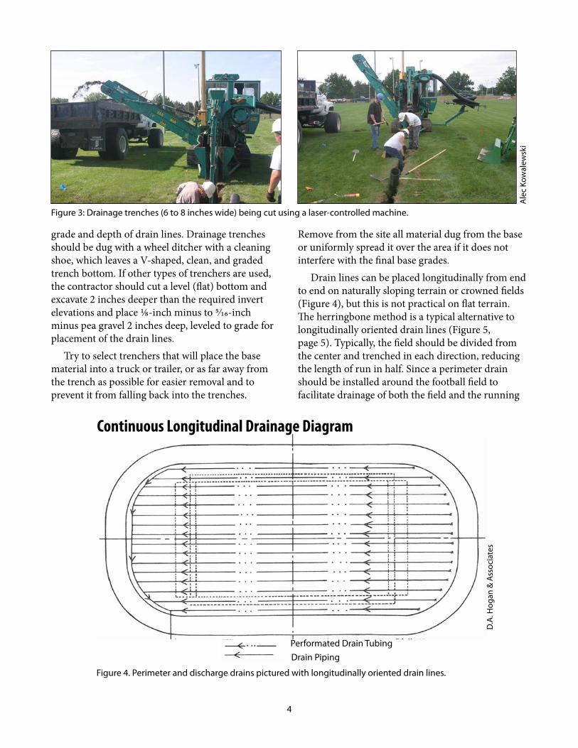
Install drain lines 16 to 24 inches below the grassed surface at a 1- to 2-percent minimum grade. Drainage trenches should be 6 to 8 inches wide and should be dug with laser-controlled machines (Figure 3, page 4). This will ensure the proper
Pit-run sand/gravel – base specificationsSieveSize
Tyler Standard ScreenU.S. Series Equiv. No.
ParticlesPassing
Millimeters Inches Percentage
87 3½ 100
40 1½ 80–100
20 3/8 70–100
Meshes/inch
1.0 16 0–100
0.25 60 0–30
0.15 100 0–15
0.10 140 0–10
0.07 200 0–5
Table 1. Particle-size Specifications for Base Material
Aerial View of a Crowned Field Ground-level, Cross-sectional View of a Crowned Field
Figure 2. Drain lines can be placed longitudinally from end to end on naturally sloping terrain or crowned fields, but this is not practical on flat terrain.
D. A
. Hog
an &
Ass
ocia
tes
4
grade and depth of drain lines. Drainage trenches should be dug with a wheel ditcher with a cleaning shoe, which leaves a V-shaped, clean, and graded trench bottom. If other types of trenchers are used, the contractor should cut a level (flat) bottom and excavate 2 inches deeper than the required invert elevations and place 1/8-inch minus to 5/16-inch minus pea gravel 2 inches deep, leveled to grade for placement of the drain lines.
Try to select trenchers that will place the base material into a truck or trailer, or as far away from the trench as possible for easier removal and to prevent it from falling back into the trenches.
Remove from the site all material dug from the base or uniformly spread it over the area if it does not interfere with the final base grades.
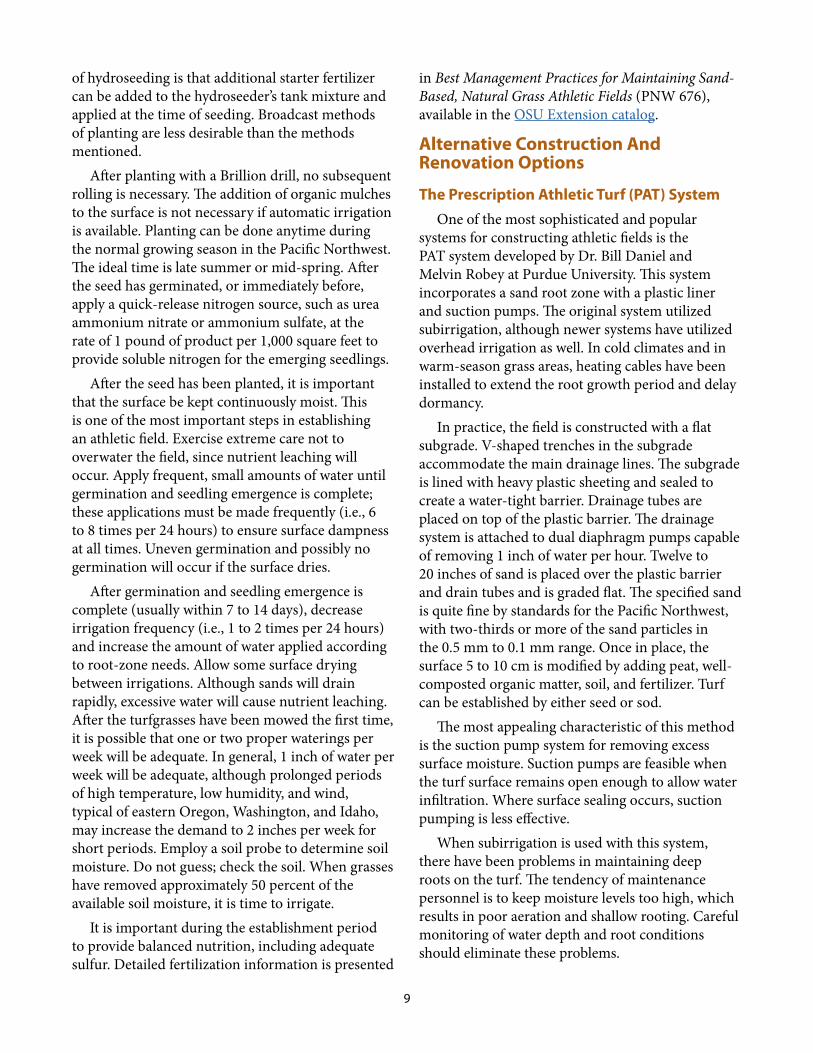
Drain lines can be placed longitudinally from end to end on naturally sloping terrain or crowned fields (Figure 4), but this is not practical on flat terrain. The herringbone method is a typical alternative to longitudinally oriented drain lines (Figure 5, page 5). Typically, the field should be divided from the center and trenched in each direction, reducing the length of run in half. Since a perimeter drain should be installed around the football field to facilitate drainage of both the field and the running
Figure 3: Drainage trenches (6 to 8 inches wide) being cut using a laser-controlled machine.
Performated Drain TubingDrain Piping
Figure 4. Perimeter and discharge drains pictured with longitudinally oriented drain lines.
Continuous Longitudinal Drainage Diagram
D.A
. Hog
an &
Ass
ocia
tes
Ale
c Ko
wal
ewsk
i

5
track, these longitudinal drain lines can be coupled with the perimeter drain and discharged into storm sewers or other suitable sites (Figure 5). Some drainage lines are manufactured with slits 360 degrees around the tubing and some are drilled with holes only on one side at 45-degree angles. In the latter case, always place the holes downward. During installation, attempt to keep soil off the drain lines and trenches. Carefully cap blind ends and properly connect and tape all joints to prevent entrance of soil material or animals.
Drainage lines spaced on 15-foot centers should be installed with 3- or 4-inch, semi-rigid drainage tubes with slits or drilled holes to facilitate inflow of water. After the drain lines are in place, backfill trenches with pea gravel (1/8 to 5/16 inch) or coarse sand to a depth of 2 to 4 inches over the top of the drain tubing to avoid migration of fine sand particles into the drain line, causing clogging of the drains (Figure 6). Manufactured filter devices wrapped around the tile or placed over the tile to prevent migration of the fine particles are not recommended; they can become clogged with fine particles and seal the drain lines.
Sand-based Athletic Field with a 4-inch Base Material Layer
Sand-based Athletic Fieldwithout a Base Material Layer
Figure 6. Cross-sectional view of drainage profile with (top) and without (bottom) a 4-inch base material layer.
Figure 5. Herringbone drain-tile system pictured with perimeter and discharge drain lines.
Performated Drain TubingDrain Piping
Herringbone Drainage Diagram
D.A
. Hog
an &
Ass
ocia
tes
D.A. Hogan & Associates

6
Extend drainage lines through the end zones to tie in with the perimeter drains near the running track. The drainage line surrounding the running track will intercept all field drains and should be 6 inches in diameter. Install catch basins around the perimeter of the field over the 6-inch drain at strategic locations for rapid evacuation of water from running tracks. About 8,000 feet of drain lines will be needed for fields like this. It may be possible to also install irrigation lines in the drain line trenches. This should be discussed with an irrigation engineer.
Irrigation Installation Irrigation is essential on sand-based fields.
Determine availability of adequate irrigation water throughout the year at an early stage while planning the installation of an athletic field. Irrigation systems should be designed and installed by competent irrigation specialists. Sand fields cannot achieve their maximum usefulness without systems to irrigate the field during dry periods. Automatic irrigation systems with safety pop-up heads are best for sand-based athletic fields. Irrigation water can be more carefully controlled from this type of system. Install irrigation heads at a grade somewhat higher than the finished surface; after the soil has settled and the grass has become well established, these heads can be lowered to their proper final height (Figures 7 and 8).
Sand SelectionThe sand rooting medium specifications are
listed in Table 2 (page 7). Ideally, the majority of the sand particles should fall between the ranges of No. 16 and No. 60 screen; however, sands with most of the particles between a No. 60 and No. 140 screen may be used for the rooting medium. With the latter, many precautions have to be followed in management to avoid slow infiltration of water caused by the accumulation of organic material and surface compaction. Always specify sand by sieve size. Most sand suppliers use Tyler Standard
Typical Automatic Irrigation System for Football/Soccer Field with a 400-meter Track
Figure 8. Typical automatic, in-ground irrigation system with pop-up heads. This system is an example; each field should be designed according to pipe sizes, pumps, and the number and gallons-per-minute flow of sprinkler heads.
C.H
. Kuh
n
Figure 7. Automatic control irrigation systems typically will have wiring to each irrigation head, or a block of irrigation heads, to provide more precise irrigation.
Ale
c Ko
wal
ewsk
i

7
Screens that classify sand particles by the number of meshes per inch. Table 1 (page 3) and Table 2 show recommended pit-run gravel and sand specifications in millimeters and sieve sizes.
Surface sand depth will vary from 4 to 12 inches depending upon the quality of the base material. Pit-run materials with high proportions of properly sized sand will allow the use of perhaps as little as 4 inches of finest quality sand for the surface.
The addition of organic material, mixed off-site into the surface sand medium, is optimal. Materials such as well-composted organic matter or fibrous sphagnum peat moss are acceptable for the organic matter amendment. Organic matter particle sizes should range from 1/8 to 3/16 inch. Avoid all materials that are coarser or finer than those indicated. Under no circumstances should decomposed peat material be used as an organic amendment on high traffic sports fields. Organic materials increase water and nutrient holding capacity and give resiliency to the surface for the first 2 to 3 years. After approximately 2 years, however, the grass plants will produce adequate organic matter. With adequate attention to fertilization programs, organic amendments can then be omitted.
If organic materials are included with the sand top mix, do the premixing off-site with bucket loaders or other mixing equipment to get a homogeneous mixture of sand and organic matter, then place the mix over the playing surface. Incorporate no more than 20 percent organic material by a loose volume with the surface mixture. It is best to have samples of both the sand and organic material sent to a qualified soil testing lab to ensure the best sand and organic material combination that will give the optimum water holding capacity and drainage for the field. Each batch of root-zone mix should be tested before it is placed on the athletic field.
Bring the surfacing or rooting medium to a flat grade over the playing surface and moisten to permit easier grading and movement without severe rutting. Fields built to these specifications do not need to be crowned because of the porous root-zone medium and installed drain lines. Practice care and caution to avoid damage to installed sprinklers and drains. Do
not use compaction devices on the surface material except for normal grading and tillage equipment.
Turfgrass Selection If the site is not sodded, seeding rates for football
and other sports fields should be 4 to 6 pounds per 1,000 square feet of certified seed. Although Poa pratensis (Kentucky bluegrass) is not well adapted to areas west of the Cascades, it is useful in seed mixtures with Lolium perenne (perennial ryegrass). The vigorous rhizome system of bluegrass helps improve sod strength and quickly fills in worn areas better than the bunch-type ryegrass. Mixtures should be 50 percent turf-type perennial ryegrass and 50 percent improved Kentucky bluegrass by weight. This will actually be 80 percent Kentucky bluegrass by seed number and 20 percent perennial ryegrass.
Bluegrass planted alone, or as blends of cultivars, will perform well east of the Cascade Mountains in Washington, Oregon, and Idaho. When certified bluegrass seed is planted alone, a seeding rate of 3 to 4 pounds per 1,000 square feet is adequate. Do subsequent overseedings, following the initial establishment, with turf-type perennial ryegrass west of the Cascade Mountains and with ryegrass alone or in mixture with bluegrass east of the Cascade Mountains. Turf-type ryegrass is known to be extremely wear tolerant and will persist under heavy traffic.
Rooting medium sand specifications
SieveSize
Tyler Standard ScreenU.S. Series Equiv. No.
ParticlesPassing
Millimeters Meshes/inch Percentage
4.5 4 100
2.0 10 95–100
1.0 16 85–100
0.5 30 50–70
0.25 60 0–30
0.10 140 0–10
0.07 200 0.5
0.01 270 0
Table 2. Particle-size Specifications for Sand Rooting

8
Turfgrass EstablishmentPacific Northwest sands are usually nutrient
deficient and require a complete range of plant nutrients. Nutrient applications should be based on soil tests; however, as a quick guide, incorporate the following fertilizer elements into the sand profile prior to establishment at the indicated rates:
• Dolomitic limestone (supplying calcium and magnesium): 100 pounds per 1,000 square feet
• Phosphorus (P): 4 pounds P2O5 phosphate per 1,000 square feet
• Potassium (K): 5 pounds K2O per 1,000 square feet
• Micronutrients: Apply a blend containing iron (Fe), manganese (Mg), molybdenum (Mo), copper (Cu), zinc (Zn), and boron (B) according to manufacturer’s recommenda-tions; or seek competent advice. Application rates will depend on the concentration of the formulation.
• Nitrogen (N): Apply 2 pounds of available nitrogen per 1,000 square feet from slowly soluble or slow-release sources of nitrogen. Sulfur-coated urea, Isobutylidenediurea (IBDU), urea formaldehyde, Polyon, or an equivalent polymer-coated, sulfur-coated urea (PCSCU) are all examples of slow-release nitrogen sources.
Do not apply fertilizer materials until the field is brought to its final grade. Lightly rototill all fertilizing materials and soil amendments into the top 4 inches of the final mix. After the fertilizer
materials have been incorporated, no surface sand movement should be allowed. Movement will displace the fertilizers, causing streaks and windrows of materials with areas of total deficiency. Following the incorporation of fertilizers, slightly moisten the field and roll with a light roller or with a Brillion drill or suitable lightweight packing device to slightly firm the surface prior to seeding.
PlantingUse a Brillion drill or comparable landscape
seeder for planting (Figure 9). This type of drill uniformly spreads the seed and presses it into close contact with the soil surface. Divide the seed in half and sow in opposite directions. This will ensure fewer skips in the planting. In areas of considerable wind movement, hydroseeding with grass seed and approximately 1,200 pounds of fiber mulch per acre has been most successful in preventing the blowout of seed and sand (Figure 10). Another advantage
Figure 9. Use a Brillion drill or comparable landscape seeder for planting.
Figure 10. Hydroseeding with grass seed and approximately 1,200 pounds of fiber mulch per acre has been most successful in preventing the blowout of seed and sand.
Ale
c Ko
wal
ewsk
iA
lec
Kow
alew
ski
9
of hydroseeding is that additional starter fertilizer can be added to the hydroseeder’s tank mixture and applied at the time of seeding. Broadcast methods of planting are less desirable than the methods mentioned.
After planting with a Brillion drill, no subsequent rolling is necessary. The addition of organic mulches to the surface is not necessary if automatic irrigation is available. Planting can be done anytime during the normal growing season in the Pacific Northwest. The ideal time is late summer or mid-spring. After the seed has germinated, or immediately before, apply a quick-release nitrogen source, such as urea ammonium nitrate or ammonium sulfate, at the rate of 1 pound of product per 1,000 square feet to provide soluble nitrogen for the emerging seedlings.
After the seed has been planted, it is important that the surface be kept continuously moist. This is one of the most important steps in establishing an athletic field. Exercise extreme care not to overwater the field, since nutrient leaching will occur. Apply frequent, small amounts of water until germination and seedling emergence is complete; these applications must be made frequently (i.e., 6 to 8 times per 24 hours) to ensure surface dampness at all times. Uneven germination and possibly no germination will occur if the surface dries.
After germination and seedling emergence is complete (usually within 7 to 14 days), decrease irrigation frequency (i.e., 1 to 2 times per 24 hours) and increase the amount of water applied according to root-zone needs. Allow some surface drying between irrigations. Although sands will drain rapidly, excessive water will cause nutrient leaching. After the turfgrasses have been mowed the first time, it is possible that one or two proper waterings per week will be adequate. In general, 1 inch of water per week will be adequate, although prolonged periods of high temperature, low humidity, and wind, typical of eastern Oregon, Washington, and Idaho, may increase the demand to 2 inches per week for short periods. Employ a soil probe to determine soil moisture. Do not guess; check the soil. When grasses have removed approximately 50 percent of the available soil moisture, it is time to irrigate.
It is important during the establishment period to provide balanced nutrition, including adequate sulfur. Detailed fertilization information is presented
in Best Management Practices for Maintaining Sand-Based, Natural Grass Athletic Fields (PNW 676), available in the OSU Extension catalog.
Alternative Construction And Renovation Options
The Prescription Athletic Turf (PAT) SystemOne of the most sophisticated and popular
systems for constructing athletic fields is the PAT system developed by Dr. Bill Daniel and Melvin Robey at Purdue University. This system incorporates a sand root zone with a plastic liner and suction pumps. The original system utilized subirrigation, although newer systems have utilized overhead irrigation as well. In cold climates and in warm-season grass areas, heating cables have been installed to extend the root growth period and delay dormancy.
In practice, the field is constructed with a flat subgrade. V-shaped trenches in the subgrade accommodate the main drainage lines. The subgrade is lined with heavy plastic sheeting and sealed to create a water-tight barrier. Drainage tubes are placed on top of the plastic barrier. The drainage system is attached to dual diaphragm pumps capable of removing 1 inch of water per hour. Twelve to 20 inches of sand is placed over the plastic barrier and drain tubes and is graded flat. The specified sand is quite fine by standards for the Pacific Northwest, with two-thirds or more of the sand particles in the 0.5 mm to 0.1 mm range. Once in place, the surface 5 to 10 cm is modified by adding peat, well-composted organic matter, soil, and fertilizer. Turf can be established by either seed or sod.
The most appealing characteristic of this method is the suction pump system for removing excess surface moisture. Suction pumps are feasible when the turf surface remains open enough to allow water infiltration. Where surface sealing occurs, suction pumping is less effective.
When subirrigation is used with this system, there have been problems in maintaining deep roots on the turf. The tendency of maintenance personnel is to keep moisture levels too high, which results in poor aeration and shallow rooting. Careful monitoring of water depth and root conditions should eliminate these problems.

10
Sportsturf™ All Weather FieldA nearly identical system called Sportsturf™
All Weather Field has been developed by Melvin Robey. This field also uses a plastic underlining with a straight sand profile modified in the surface with bark. Both the PAT and Sportsturf systems emphasize flat playing surfaces free of the crowns used in other fields.
Hy-play SystemA third alternative is the Hy-play system. Using
this approach, the area is typically excavated to a depth of 12 inches. Drainage tubes 4 inches in diameter are placed on or trenched into the subgrade on 10-foot centers. In some cases the drain tubes have been covered with a fine mesh filter cloth, which theoretically will prevent the tubes from becoming clogged by fine sand or soil particles. After drainage installation, a 12-inch, sand-based, root-zone medium is placed over the subgrade. Root-zone sand specifications are similar to those outlined in the guidelines of this publication. The field is equipped with an automatic irrigation system. Turf is generally established using washed sod, but seed may also be used. An additional feature is a fertilizer injection system that distributes fertilizer through the irrigation system.
Performance of Hy-play fields has been variable. One problem has involved the use of washed sod. In theory, all soil is removed during the washing procedures, which eliminates the possibility that fine soil particles will seal the surface of the field. In practice, complete soil removal has been difficult and surface sealing has been known to occur due to the soil layer. Establishing this type of field from seed would avoid this problem.
United States Golf Association (USGA) Green Section Recommendations
A fourth alternative would be athletic field construction according to the USGA Green Section Recommendations for a Method of Putting Green Construction. The field is first excavated to the subgrade, which is contoured to allow drainage. Drainage trenches are cut 6 inches into the subgrade in either grid or herringbone patterns. Drain tubes are installed and the trenches are backfilled with 1/2- to 3/8-inch-diameter pea gravel. An additional 4 inches of pea gravel is placed over the subgrade.
Next, an optional 11/2- to 2-inch layer of uniform, very coarse sand – size 1 mm – may be placed over the pea gravel. This optional layer is included to prevent migration of the top-mix soil into the pea gravel base.
The top mix is created by blending locally available sand, soil, and organic matter to meet minimum standards for infiltration, percolation, porosity, bulk density, and water retention. The final mix ideally will contain no more than 10 percent particles larger than 1 mm, and no more than 25 percent of the particles should be between 0.25 and 0.1 mm, which is similar to specifications in Table 2 (page 7). In addition, the soil mix should contain less than 5 percent silt and 3 percent clay.
This system requires detailed testing to prescribe top-mix proportions (for a current list of accredited USGA putting green top-mix testing laboratories see Appendix A, page 13).
The Cambridge SystemThe Cambridge System of athletic field renovation
is a method for improving drainage on existing fields, but it is extensive enough to be included with this discussion of construction techniques. The system, as developed in Europe, uses a combination of subsoil drains and sand-filled slits cut into the surface of the existing field. As recommended by Cambridge Soil Services of America, subsoil sideline drains should be installed from the 50-yard line of football fields to the goal. To accommodate high volumes of water, more than one 4-inch corrugated pipe can be installed in the trench in a layered arrangement. Cross field drains run from the center of the field to the sideline drains and are spaced 15 feet apart. On crowned fields, 2-inch pipe is recommended and on flat fields, 4-inch pipe.
After subsoil drains are installed, surface drains are added. The first step is sand injection, which involves cutting slots 0.6 inches wide on 19-inch centers at right angles to cross field drains. The patented machinery required for this operation loosens soil to a 15-inch depth, and injects sand to 9 inches. Since sand is backfilled to the surface, it allows rapid entry of surface water and therefore speeds drainage. The second phase of surface drainage involves sand grooving. This is essentially a shallow form of sand injection and is done at right angles to the sand injection slits. The grooving
11
machinery used for installation can also top dress the field surface with sand to reduce the chance that grooves or slits will become covered by native soil. The addition of grooves further reduces the distance water must travel to reach a drainage zone.
In theory, this system should work well, and it has apparently been used successfully in Europe. The technique has only recently been introduced into the United States, and time will tell whether it works under PNW conditions. Potential problems include a scarcity of special equipment for the sand injection and grooving procedures, and the possibility of surface sealing, which would prevent water from entering either slits or grooves. Under these conditions, the drainage rate would slow dramatically.
With the exception of the last method discussed, it should be obvious that all systems of athletic field construction use a porous and stable root-zone mixture as the major component. Base decisions on which to use on cost, need for specific features, and the performance record in the area where the field is to be used.
Renovation OptionsNot every facility can afford one of these quality
systems. Small schools and parks departments often do not have enough money or the type of intensive use that would require these construction methods. The following four methods may improve existing field conditions, but will not provide the ultimate quality of more intensive systems:
1. Improvement of field centers: Football is played for the most part in the center 60 to 70 feet of a 160-foot-wide playing surface. This is where fields typically wear out or become muddy or unplayable. This field zone can be significantly improved through excavation, installation of drainage lines, base material, and a sand root-zone mixture. Field center improvement can be made at approximately one-third the cost of rebuilding the entire field.It is wise to install drain lines for the entire field even when only the center is being reconstructed. If drainage lines are installed throughout the field, carefully follow the instructions already described. Also, an additional 4 inches or more of sand can be
uniformly spread over the remainder of this field to help protect the soil beneath from compaction and puddling.
2. Uniform shallow sand profile to protect surfaces. Many fields have been established by utilizing a shallow sand profile of approxi-mately 4 inches over moderately permeable subsoils. It is useless to install drainage lines in soils that have high water permeability rates. When soils are naturally well drained it becomes only essential to protect the surface to prevent compaction and puddling from inten-sive traffic. A sand layer of approximately 4 inches will provide protection. Athletic fields, even with very difficult subsoils, have been greatly improved with this method. Soils with high silt and clay contents and slow permeabil-ity rates can be used a much greater portion of the year by sand blanketing than if left in their normal state. It’s best to loosen subsoils with tillage equipment prior to blanketing with sand. This will promote and maintain better infiltration rates. Never mix sand into existing soil with this method.
3. Utilizing existing native materials. Most sports fields, especially in small communi-ties, are built from existing native materials. Loamy sand and sandy loam soils are probably best for this type of construction, but they can develop serious problems from puddling and compaction if good management programs are not carried out. Soils with textures as heavy as silt loams or silty clay loams have been used in construction of sports fields with reason-able results, provided that play distribution and intensity are regulated and dense stands of grass are maintained. It is most desirable with this method to provide alternate fields to allow renovation and improvement of damaged areas.Football fields built from residual materials should be built with essentially no crown. Due to the dense nature of grass growth, water movement from the center of the field to side-lines is extremely slow even with the most severe crowns. Crowning in this case simply increases the cost of grading operations. If sub-soils under this method of construction have

12
little or no permeability, install drainage lines to intercept and carry away excessive water. These lines should be installed by methods already described. In later years the option is open to reconstruct the field utilizing the shal-low sand profile.In order to accommodate regulation play, it is important to practice the highest quality maintenance program. This would include aerification, overseeding to maintain dense populations of grass, and careful watering programs to avoid soil saturation, especially at or near time of play. Good nutritional programs will ensure adequate growth and recovery from wear. This alternative is the cheapest option of the three described, and to be successful it requires careful maintenance combined with carefully regulated use.
4. Sand cap build-up system: The fourth renova-tion option is the sand cap build-up system, which can be done in two simple steps:
1. Install intercept drain tiles into existing fields, and then
2. Build up a sand layer over the native soil using sequential sand top-dressing applica-tions (Figure 11). The general idea is to cut drains into the existing field running length-wise on 6- to 20-foot centers, depending on the surface grade and slope; put drain tile in the lines; and backfill with coarse sand or fine gravel. After the drain lines have
been backfilled to field level, begin a 2-year, top-dressing program with the goal of devel-oping a 2-inch, sand-based profile over time.
References Cockerham, S.T. 1984. “The biggest race of all: L.A. Coliseum turf team races against clock to solve turf problems at 1984 Olympics site.” Landscape Manage. 23(2):p. 32–33.Daniel, W. H. 1973. “New natural turf system aids players: The PAT system.” Proceedings of the 43rd Annual Michigan Turfgrass Conference. 2: 67–69. Retrieved Dec. 9, 2014. http://archive.lib.msu.edu/tic/mitgc/article/197367.pdf Kowalewski, A., J. R. Crum, and J. N. III Rogers. 2009. “Using drain tile installation and sand top-dressing to develop a built-up sand-capped system over time.” Sports Turf Manager. 22(2): 13–15, 17.Moreland, J.W. 1986. “Sports Turf Drainage: A Battle of Two Forces.” SportsTurf. 18, 20, and 21.Robey, M. J. 1979. “SportsTurf all-weather fields: Natural grass at its best!” 34th Annual Texas Turfgrass Conference Proceedings. Texas A & M University, College Station, TX. 31–35.USGA Green Section Staff. 2014. “USGA Recommendations for a Method of Putting Green Construction.” United States Golf Association, Far Hills, NJ. Retrieved Dec. 9, 2014. http://www.usga.org/course_care/articles/construction/greens/Green-Section-Recommendations-For-A-Method-Of-Putting-Green-Construction/
Figure 11. The sand cap build-up method utilizes drain tile installation and then sequential top-dressing applications to develop a sand-based system over time.
Ale
c Ko
wal
ewsk
i

13
DedicationThis publication is dedicated to Mr. Don A.
Hogan, P.E., founder of D.A. Hogan & Associates and founding member of the Northwest Turfgrass Association (NTA) for his dedication to the betterment of athletic fields in the Pacific Northwest and around the world. Don passed away in November 2013, but established a fund within the NTA to support athletic field research for the PNW.
That fund will continue into the future for the betterment of athletic fields. Thank you to D. A. Hogan & Associates for use of the architectural drawings for field construction in this publication.
AcknowledgementsThanks to Dr. W. J. Johnston, Washington State
University, and T. McCammon, University of Idaho, for their suggestions as manuscript reviewers.
Organization Contact City, State Country Phone Fax Comm. code
Brookside Laboratories, Inc.
Jackie Brackman
New Bremen, OH
United States 419-977-2766
419-977-2767
C3
Dakota Analytical, Inc.
Randy Dufault East Grand Forks, MN
United States 701-746-4300
218-773-3151
C1
European Turfgrass Laboratories Limited
Sharon Singleton-Bruce
Stirling FK7 7RP
United Kingdom
0044-1786-449195
0044-1786-449688
C1
Hutcheson Technical & Soil Services
Richard De Gans
Huntsville ON P1H-2P2
Canada 1-705-789-4457
705-789-1049
C2
ISTRC New Mix Lab, LLC
Robert Oppold Lenexa, KS United States 800-362-8873
913-829-4013
C1
Sports Turf Research Institute
Christian Spring
West Yorkshire BD16 1AU
United Kingdom
44-01274 565131
44-01274 561891
C1
Thomas Turf Services, Inc.
James Thomas College Station, TX
United States 979-774-1600
979-774-1604
C1
Tifton Physical Soil Testing Laboratory, Inc.
T. Powell Gaines
Tifton, GA United States 229-382-7292
229-382-7992
C1
Turf & Soil Diagnostics, Inc.
Duane Otto Trumansburg, NY
United States 855-769-4231
607-387-9499
C1
Turf & Soil Diagnostics, Inc.
Duane Otto Linwood, KS United States 855-769-4231
913-723-3701
C1
Appendix A: Accredited USGA Putting Green Top-mix Testing Laboratories
Commercial Codes: C1–Available for commercial services; C2–Conditionally available for commercial services; C3–Not normally available for commercial services.
© 2015 Oregon State University.
Pacific Northwest Extension publications are produced cooperatively by the three Pacific Northwest land-grant universities: Oregon State University, Washington State University, and the University of Idaho. Similar crops, climate, and topography create a natural geographic unit that crosses state lines. Since 1949, the PNW program has published more than 600 titles, preventing duplication of effort, broadening the availability of faculty specialists, and substantially reducing costs for the participating states.
Published and distributed in furtherance of the Acts of Congress of May 8 and June 30, 1914, by the Oregon State University Extension Service, Washington State University Extension, University of Idaho Extension, and the U.S. Department of Agriculture cooperating.
The three participating Extension services offer educational programs, activities, and materials without discrimination based on age, color, disability, familial or parental status, gender identity or expression, genetic information, marital status, national origin, political beliefs, race, religion, reprisal, sex, sexual orientation, veteran’s status, or because all or a part of an individual’s income is derived from any public assistance program. The Oregon State University Extension Service, Washington State University Extension, and University of Idaho Extension are an AA/EOE/Veterans/Disabled.
Published September 2015.