b series open flued warm air · pdf fileinstallation, commissioning and servicing...
TRANSCRIPT

INSTALLATION, COMMISSIONING AND SERVICING INSTRUCTIONS
"B" SERIES OPEN FLUED WARM AIR HEATERS
STORE NEAR HEATER
Installer : ...................................................................................................................................................... Address : ...................................................................................................................................................... Place : ...................................................................................................................................................... Telephone : ................................................................. Date : .........................................................................
Distributed by: J O H N S O N and S T A R L E Y. Ltd Rhosili Road, Brackmills, Northampton NN4 7LZ. Telephone: 01604 762881 Telefax: 01604 767408 E-mail: [email protected]

"B" SERIES WARM AIR HEATERS
Installation, Commissioning and Servicing Instructions Publication No. ZZ594/10 August 2000 G.C.No.s: B12 - 42 416 95 B17 - 42 416 96 B23 - 42 416 97 B28 - 42 416 98 B34 - 42 451 01
WARNING: THESE APPLIANCES MUST BE EARTHED 1. GENERAL DESCRIPTION The Johnson & Starley 'B' Series heaters are open-flued, fan assisted, ducted warm air heaters, which can be supplied for either upward discharge (upflow) or downward discharge (downflow) applications. Air heater outputs range from 12.0 kW(43.2 MJ/h, 40,940 Btu/h) to 36.0 kW(129.6 MJ/h, 122,830 Btu/h). 2. COMPONENTS CHECK 1 Flue outlet 2 Draught diverter 3 Combined fan and limit switch 4 Multifunctional control 5 Pilot burner assembly 6 Mains electrical connection 7 Summer air circulation switch 8 Air circulating fan 9 Air filter 10 Control Panel 11 Auto transformer 12 Main burner assembly 13 Data badge 14 Gas connection 1/2in BSP 15 240V/24V transformer 16 Piezo unit 17 Spillage switch Fig.1
3809.tif Item supplied loose (not shown): Gas service cock ½"BSP NOTE: Fig.1 shows the component layout for an Upflow model. For 'D' type (Downflow) models, the
component layout is similar (burner and fan chambers are reversed), with the exception of the air filter (see Section 8, para. 8.7.2).
THESE APPLIANCES CONFORM TO BS 800
2 3. GENERAL REQUIREMENTS 3.1 Related Documents (refer to latest issues) This appliance MUST BE installed in accordance with the relevant requirements of the Gas Safety
(Installation and Use) Regulations, the Building Regulations and the I.E.E. Wiring Regulations for electrical installations.
It should be in accordance also with any relevant requirements of the local Region of British Gas and Local Authority and the relevant recommendations of the following Codes of Practice:-
- Building Standards (Scotland)(Consolidation) Regulations. - Building Regulations. - Gas Safety (Installation and Use) Regulations (as amended). - Institute of Electrical Engineers (I.E.E.) Regulations. - BS6891 Specification for Installation of Low Pressure Gas - Pipework of up to 28mm (R1) in Domestic Premises (2nd family gases). - BS5440 Pt.1 (Flues for Gas Appliances). - BS5440 Pt.2 (Air Supply for Gas Appliances). - BS5864 Installation of Gas Fired Ducted Air Heaters. - British System Design Manual 'Gas Fired Warm Air Heating'. - Local Authority Bylaws. IMPORTANT: It is the law that all gas appliances are installed by competent persons e.g. Corgidealers, in accordance with the Gas Safety (Installation and Use) Regulations (current edition). Failure to install appliances correctly could lead to prosecution.
3 4. INSTALLATION 4.1 Heater Compartment and Clearances (see BS5864) When the heater is fitted into a compartment, the following minimum clearances are needed (all
heaters):- Front: 150 mm (6in) Sides: 50 mm (2in) Rear : 50 mm (2in) For service access, a minimum front clearance of 600mm(24in) is needed. Consideration should also be given to the space required for the removal and replacement of the
filter, entry of gas and electrical supplies, and in compartment installations, to the removal of the heater.
The compartment must be of a fixed rigid structure and the internal construction must be
half-hour-fire-resistant from internal fire; the inside lining or finishing of the enclosure must be non-combustible or a class 1 finish - see also BS476.
In airing cupboard installations, the part used as the air heater compartment must comply with the
relevant sections of BS5864 and must be completely separated by either a non-combustible partition or a perforated metal partition with the perforations not exceeding 13mm(½in).
The secondary flue must be a tight fit where it passes through the partition and must be suitably protected (see BS5440: Part 1).
In under-stairs installations, the compartment must comply with the relevant section of BS5864,
provided that, in addition, all internal surfaces including the base, are non-combustible or lined with non-combustible material.
4.2 Ventilation and Combustion Air The room or internal space in which the heater is installed requires a permanent air vent. The air vent
should be either direct to outside air or to an adjacent room or internal space (other than a toilet or bathroom) that itself has an equivalent air vent to outside.
Minimum effective areas of permanent air vent:- B-12(D) - 45 cm² (7 in²) B-17(D) - 81 cm² (13 in²) B-23(D) - 117 cm² (18 in²) B-28(D) - 153 cm² (24 in²) B-34(D) - 185 cm² (29 in²) Combustion air may be introduced, if required, via a dampered pipe, connected to a ventilated area.
4 The damper should be adjusted to control combustion air flow to the following flow rates:-
Heater Type Pipe Dia. mm (in) Flow rate m3/s (cfm) Velocity m/s (ft/min)
B-12 (D) B-17 (D) B-23 (D) B-28 (D) B-34 (D)
100 125 125 125 150
0.009 (17.9) 0.015 (29.9) 0.018 (36.2) 0.023 (45.1) 0.027 (54.2)
1.15 (205) 1.22 (219) 1.48 (265) 1.85 (331) 1.53 (276)
If this arrangement is used, a non-closable warm air register MUST be provided in the same area as
the front of the air heater or heater compartment if a return air grille is not located in that area. When installed in a compartment, two permanent ventilation openings are required, one at high level
and one at low level, both communicating on the same wall or face either directly with outside air or with a ventilated room or space.
The minimum areas are specified in TABLE 1. If any room or area from which air is drawn for ventilation or combustion contains an extract fan, the
permanent vents must be sized to ensure that the operation of the appliance(s) at full rate is/are not adversely affected.
A spillage test as specified in Section 5.16 should be carried out and any remedial work undertaken. TABLE 1
B-12 (D) B-17 (D) B-23 (D) B-28 (D) B-34 (D)
Ventilated from inside
building
Low level grille High level grille
306 cm² (47 in²) 153 cm² (24 in²)
450 cm² (70 in²) 225 cm² (35 in²)
594 cm² (92 in²) 297 cm² (46 in²)
738 cm² (114 in²) 369 cm² (57 in²)
864 cm² (134 in²) 432 cm² (67 in²)
Ventilated
from outside building
Low level grille High level grille
153 cm² (24 in²) 77 cm² (12 in²)
225 cm² (35 in²) 113 cm² (18 in²)
297 cm² (46 in²) 149 cm² (23 in²)
369 cm² (57 in²) 185 cm² (29 in²)
432 cm² (67 in²) 216 cm² (33 in²)
4.3 Duct System Refer to British Design Manual - Gas Fired Warm Air Heating. 4.4 Return Air All return air must be POSITIVELY ducted from outside the compartment to the unit. It is recommended that the return air duct is not ducted directly from the main living area, but from a
convenient central area serving the remainder of the dwelling.
5 4.4.1 Downflow models: Connect ONLY to the top of the heater. 4.4.2 Upflow models: Connect to the base or to either side of the heater. It will be necessary to cut a hole in either the base or one of the side panels. Refer to Fig.6 for details. The return air system should be constructed of fire-resistant material. The flue must not run through
an area serving as a return air path. It is extremely important that the correct size of return air grilles and ducting is used. For heaters on maximum output, the return air duct size should be sufficient to ensure that the air
velocity in the duct does not exceed 4 m/s (800 ft/min). Free area of the return air grille(s) should be such that the velocity of air through the grille(s) does
not exceed 2 m/s (400 ft/min). An adequate and unobstructed return air path is essential from areas not served by a directly ducted return, and to which warm air is delivered. All such rooms should be fitted with relief grilles which have a free area of 0.0088 m2/kW (1 in2/250 Btu/h) of heat supplied to the room.
The only exceptions are kitchens, bathrooms and w.c's. All ductwork in the room or internal space in which the heater is installed must be secured
mechanically, and sealed with ducting tape. 4.5 Warm Delivered Air All ductwork, including riser ducts, should be fully insulated with 50 mm (2 in) glass fibre or
similar. If short extended duct runs are taken below floor level these should be similarly insulated, and in addition wrapped with a sound vapour-proof barrier, and protected from crushing.
The duct system should be carefully designed (as given in the guidelines in the British System Design Manual) to suit the needs of its specific heating requirements and building layout.
The type of duct system, ie. radial/extended plenum/stepped should be installed using the least number of fittings to minimise air flow resistance.
The warm air plenum, which equalises the air pressure to the supply ducts, must be constructed to support the weight of the heater, which must be secured to the plenum with screws on at least two sides, and sealed using self-adhesive foam strip, ducting tape or sealing compound.
4.6 Gas (see BS5864, Clause 12 and BS6891) An independent gas supply line from the meter is to be preferred wherever possible. However, when
this is not possible, the line must be capable of taking the complete input of the heater and all other gas appliances being served by this same line.
This supply should be suitably sized to conform to British Standards requirements of no more than 1.0 mbar (0.4 in wg) pressure drop (see table of discharge in BS6891).
The union gas cock (supplied) must be fitted in the gas inlet of the heater for easy isolation during servicing.
The gas pipe should be so fitted and installed as to be durable, substantial and gas tight. Gas entry to the air heater is through either side to a Rc½ (½in BSP) external (taper) thread.
NOTE: When entry is from the right-hand side, ensure that the route of the gas feed pipe does not obstruct removal of the burner assembly for servicing.
4.7 Electrical Supply All wiring external to the appliance must be installed in accordance with Institution of Electrical
Engineers (I.E.E.) Regulations for electrical installations, and any other local regulations which apply.
Connect mains electrical supply to the terminal block provided (item 6, Fig.1).

6 4.8 Flues (see British Standard BS5440 Pt.1 Flues) 4.8.1 All joints shall be soundly sealed.
4.8.2 The flue should be kept as short and warm as possible.
4.8.3 Sufficient support brackets shall be installed to bear the weight of the total flue system.
4.8.4 The spigot connection of the heater draught diverter will accept internally the spigot end of a non-asbestos flue to BS567 or twin wall metal flue to BS715 of nominal 100mm (4in) diameter for B12 appliances, 125mm (5 in) nominal diameter for B17 and B23 appliances and 150 mm (6in) for B28 and B34 appliances. (Note: The B17 upflow flue pipe may be 100mm if the initial vertical length is 1 meter or more)
4.8.5 A split collar should be fitted to provide for flue maintenance or inspection.
4.8.6 The flue shall be in accordance with the Building Regulations with regard to clearance and shielding from combustible materials.
4.8.7 All materials shall be in accordance with Building Regulations requirements. 4.8.8 The flue should run as vertically as possible. Horizontal runs should be avoided if at all possible and
any directional change should be as gentle as possible. If there is any doubt about the flue configuration, the equivalent flue height should be determined (see 4.8.10)
4.8.9 If the appliance to be fitted is a replacement, the old appliance should be checked for signs of
spillage prior to commencement of the installation and appropriate action taken. i.e. check flue system and renew as necessary.
4.8.10 It is recommended that at least 600mm of vertical flue should be provided from the top of the
draught diverter (for new installations this shall be incorporated into the flue design). However, when carrying out replacement installations, an existing flue system may be encountered, where the vertical flue above the draught diverter to the first bend is less than 600mm. In the first instance, the installer must judge whether this distance can be achieved practicably by some means. Where this is not practicable, the existing flue system may be used, providing there is no evidence of spillage from the old appliance (see 4.8.9 above). Every effort must be made, however, to ensure that the existing flue complies in every other way to BS 5440 Part 1, including the visual inspection, flue flow and spillage test described in 4.3.2 of the above standard. Flue configurations may be assessed in terms of equivalent vertical height - details are given in 4.8.11. For air heaters, the minimum equivalent vertical height is 1 metre. The installer must make a judgement based on his knowledge and experience and the examination and testing described above as to whether an existing flue system can be used.
Note: Ventilation of the compartment, room or internal space in which the appliance is to be installed must be checked for compliance with the requirements of BS 5440 Part 2 ( Ref Section 3 of these instructions) and upgraded as necessary
4.8.11 Calculation method for flue sizing: ( from BS 5440: Part 1, Appendix A)
a. This appendix provides a procedure for estimating whether a given flue design is likely to ensure full clearance of combustion products.
b. The procedure is based on calculating the ‘equivalent height’ of the flue under consideration, i.e. that height of the straight vertical circular flue pipe of specific size which will produce the same flow rate as the flue under consideration. The equivalent height is calculated from the formula overleaf :
7 (Ki + Ko ) e
He = Ha x (Ki + Ko)a - KeHa + Sum K
where: He is the height of the equivalent flue;
Ha is the vertical height of the actual or proposed flue;
Ki is the inlet resistance of the flue;
Ko is the outlet resistance from the flue;
subscript e refers to the equivalent flue diameter;
subscript a refers to the actual or proposed flue diameter;
Ke is the resistance per unit length of the equivalent flue;
Sum K is the resistance (other than the inlet and outlet resistance) of the actual or proposed flue.
Note: K and Sum K are obtained from Table 2. Ko and Ki are obtained from Table 3.
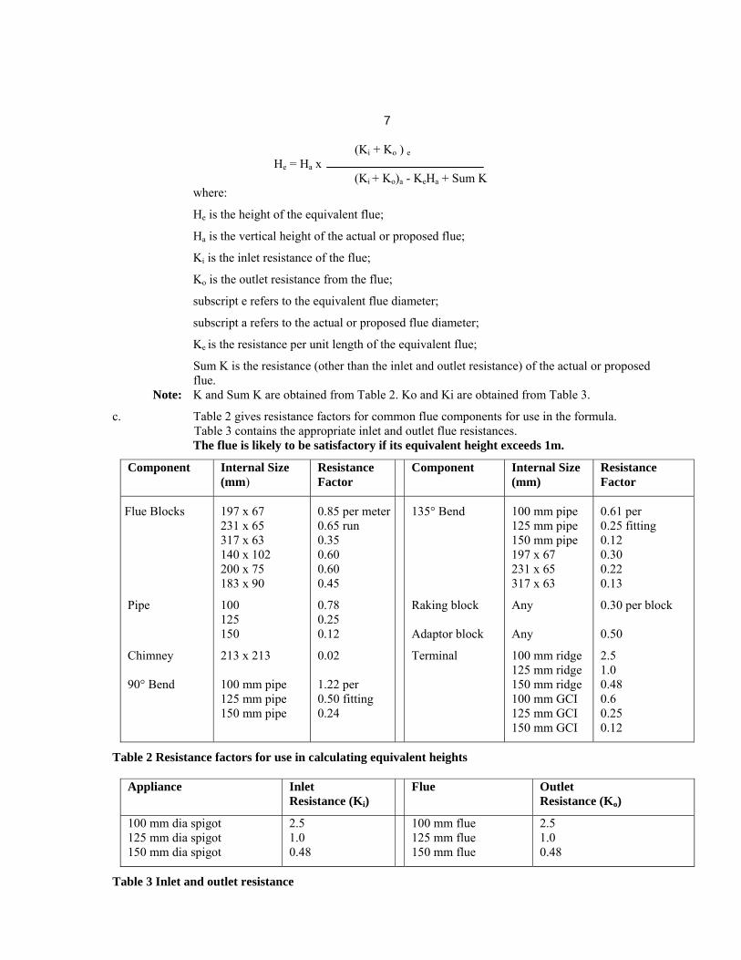
c. Table 2 gives resistance factors for common flue components for use in the formula. Table 3 contains the appropriate inlet and outlet flue resistances.
The flue is likely to be satisfactory if its equivalent height exceeds 1m.
Component
Internal Size (mm)
Resistance Factor
Component
Internal Size (mm)
Resistance Factor
Flue Blocks Pipe Chimney 90° Bend
197 x 67 231 x 65 317 x 63 140 x 102 200 x 75 183 x 90 100 125 150 213 x 213 100 mm pipe 125 mm pipe 150 mm pipe
0.85 per meter 0.65 run 0.35 0.60 0.60 0.45 0.78 0.25 0.12 0.02 1.22 per 0.50 fitting 0.24
135° Bend Raking block Adaptor block Terminal
100 mm pipe 125 mm pipe 150 mm pipe 197 x 67 231 x 65 317 x 63 Any Any 100 mm ridge 125 mm ridge 150 mm ridge 100 mm GCI 125 mm GCI 150 mm GCI
0.61 per 0.25 fitting 0.12 0.30 0.22 0.13 0.30 per block 0.50 2.5 1.0 0.48 0.6 0.25 0.12
Table 2 Resistance factors for use in calculating equivalent heights
Appliance
Inlet Resistance (Ki)
Flue
Outlet Resistance (Ko)
100 mm dia spigot 125 mm dia spigot 150 mm dia spigot
2.5 1.0 0.48
100 mm flue 125 mm flue 150 mm flue
2.5 1.0 0.48
Table 3 Inlet and outlet resistance

8 d. Worked Calculation Example:
A warm air unit with a 100 mm diameter flue spigot, fitted with a pre-fabricated flue system leading to a ridge tile in the loft (refer Fig. 2):
From table 2: Kia Inlet resistance of actual flue = 2.5
Koa Outlet resistance of actual flue = 2.5 Kie Inlet resistance of equivalent flue = 2.5 Koe Outlet resistance of the actual flue = 2.5
From table 3: Other resistances of actual flue: Terminal = 2.5
Pipe bend ( 2 x 0.61) = 1.22 Pipe (4 x 1m @ 0.78) = 3.12 (5 x 0.3m @ 0.234) = 1.17
Sum K = 8.01 Equivalent height: From the formula (2.5 + 2.5)
He = 6.2 x (2.5 + 2.5) - (0.78 x 6.2) + 8.01
He = 3.793 This flue exceeds 1.0m equivalent height and is therefore satisfactory 4.8.12 Where flue blocks are used, builders should ensure that no obstruction is created during erection. The
installer should ensure that the connection flue does not project beyond the internal wall of the flue blocks and that there is provision for examination and servicing.
4.8.13 Important: Before installing the appliance, carry out a visual check of the flue system as directed in the relevant section of BS5440 Pt.1, then check the flue performance as follows:-
a. Close all doors and windows in the room in which the appliance is to be installed. b. Introduce some heat into the flue, using a blow torch or other means.
c. Carry out a flow visualisation check with a smoke pellet at the intended position for the appliance. Ensure that there is discharge of smoke from the correct terminal only, and no spillage into the room.
Smoke coming out of other than the correct terminal only, or a down draught or ‘no flow’ condition, indicates that the flue has failed the test, and the appliance shall not be connected until the defect has been found and rectified, and the test satisfactorily completed.
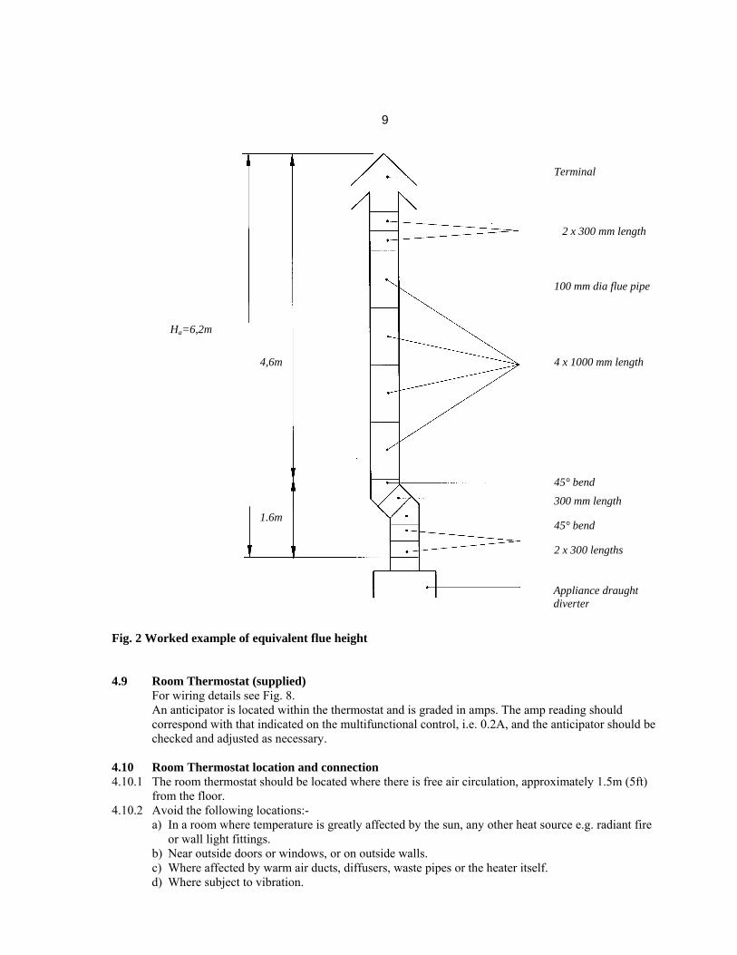
9
2 x 300 mm length
Fig. 2 Worked example of equivalent flue height 4.9 Room Thermostat (supplied) For wiring details see Fig. 8. An anticipator is located within the thermostat and is graded in amps. The amp reading should
correspond with that indicated on the multifunctional control, i.e. 0.2A, and the anticipator should be checked and adjusted as necessary.
4.10 Room Thermostat location and connection 4.10.1 The room thermostat should be located where there is free air circulation, approximately 1.5m (5ft)
from the floor. 4.10.2 Avoid the following locations:- a) In a room where temperature is greatly affected by the sun, any other heat source e.g. radiant fire
or wall light fittings. b) Near outside doors or windows, or on outside walls. c) Where affected by warm air ducts, diffusers, waste pipes or the heater itself.
d) Where subject to vibration.
Terminal
4 x 1000 mm length
100 mm dia flue pipe
45° bend
Appliance draught diverter
2 x 300 lengths
45° bend
300 mm length
Ha=6,2m
4,6m
1.6m
10 5. COMMISSIONING 5.1 Ensure that gas and electrical supplies to the appliance are off. 5.2 Remove the large front panel from the air heater and check that the filter, fan and fan compartment
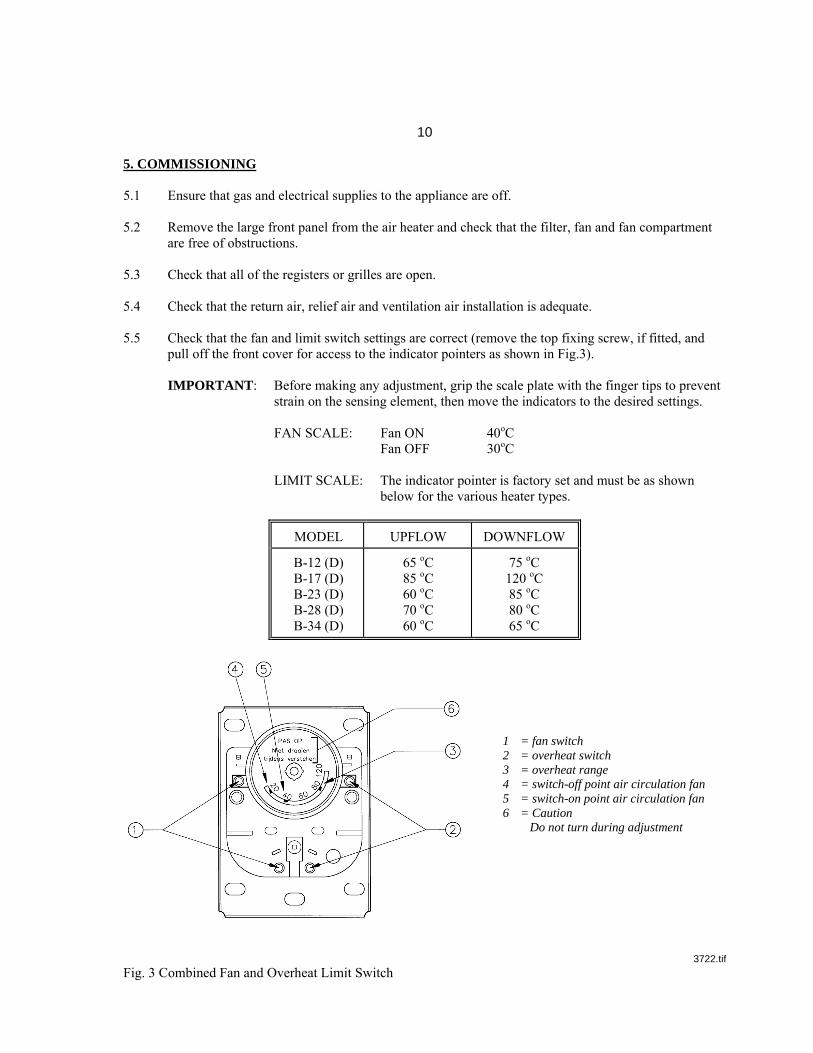
are free of obstructions. 5.3 Check that all of the registers or grilles are open. 5.4 Check that the return air, relief air and ventilation air installation is adequate. 5.5 Check that the fan and limit switch settings are correct (remove the top fixing screw, if fitted, and
pull off the front cover for access to the indicator pointers as shown in Fig.3). IMPORTANT: Before making any adjustment, grip the scale plate with the finger tips to prevent
strain on the sensing element, then move the indicators to the desired settings. FAN SCALE: Fan ON 40oC Fan OFF 30oC LIMIT SCALE: The indicator pointer is factory set and must be as shown
below for the various heater types.
MODEL UPFLOW DOWNFLOW
B-12 (D) B-17 (D) B-23 (D) B-28 (D) B-34 (D)
65 oC 85 oC 60 oC 70 oC 60 oC
75 oC 120 oC 85 oC 80 oC 65 oC
1 = fan switch 2 = overheat switch 3 = overheat range 4 = switch-off point air circulation fan 5 = switch-on point air circulation fan 6 = Caution Do not turn during adjustment
3722.tif
Fig. 3 Combined Fan and Overheat Limit Switch
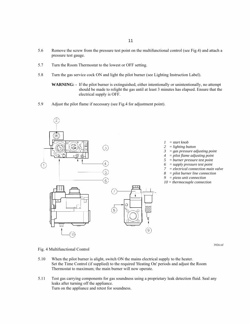
11 5.6 Remove the screw from the pressure test point on the multifunctional control (see Fig.4) and attach a
pressure test gauge. 5.7 Turn the Room Thermostat to the lowest or OFF setting. 5.8 Turn the gas service cock ON and light the pilot burner (see Lighting Instruction Label). WARNING: - If the pilot burner is extinguished, either intentionally or unintentionally, no attempt
should be made to relight the gas until at least 3 minutes has elapsed. Ensure that the electrical supply is OFF.
5.9 Adjust the pilot flame if necessary (see Fig.4 for adjustment point).
1 = start knob 2 = lighting button 3 = gas pressure adjusting point 4 = pilot flame adjusting point 5 = burner pressure test point 6 = supply pressure test point 7 = electrical connection main valve 8 = pilot burner line connection 9 = piezo unit connection 10 = thermocouple connection
3926.tif
Fig. 4 Multifunctional Control 5.10 When the pilot burner is alight, switch ON the mains electrical supply to the heater. Set the Time Control (if supplied) to the required 'Heating On' periods and adjust the Room
Thermostat to maximum; the main burner will now operate. 5.11 Test gas carrying components for gas soundness using a proprietary leak detection fluid. Seal any
leaks after turning off the appliance. Turn on the appliance and retest for soundness.
12 5.12 Allow the heater to operate for 15 minutes, then check and, if necessary, adjust the burner pressure to
the output required (see Fig.4 for adjustment point and Table 4 for pressure settings). 5.13 To adjust the burner pressure: Remove the cover from the gas pressure adjusting point on the
multifunctional control (see Fig.4), and turn the flow rate screw clockwise to increase, anti-clockwise to decrease.
5.14 Remove the pressure test gauge and replace the covers on the pilot flame and gas pressure
adjustment points. 5.15 Automatic controls check - lighting the heater and allowing it to run for a short time checks these
controls. 5.15.1 With Time Control (if supplied) ON, increase the Room Thermostat setting slowly until the main
burner ignites. Shortly afterwards, the fan will start to run. When room temperature is under control, the main burner will switch off, followed shortly by the
fan. When the room temperature falls slightly, the burner will re-ignite followed by fan operation. 5.16 Safety checks 5.16.1 Check 'fail safe' operation of the multifunctional control by turning off the gas at the inlet gas cock
and checking that the control fails safe (loud click heard from control) within 60 seconds. 5.16.2 Check the over-heat control by operating the heater with the main burner alight and the fan
disconnected at the terminal strip on the auto transformer (ref. Fig.8) - the main burner must extinguish within 2-3 minutes.
5.16.3 Check the flue for efficient operation:- With the heating system ON, all doors closed and any extractor fans running, use the following
procedure:- Run the appliance for twenty minutes to pre-heat the flue. Hold a lighted taper or a smoke match in the area of the draught deflector plate in the water heater
compartment. Spillage of combustion products is indicated by displacement of the flame or smoke away from the
draught diverter. 5.17 Balance the Warm Air System (refer to British System Design Manual - Gas Fired Warm Air
Heating) with the Control Panel in place and the air heater having been operating for 15 minutes. N.B. The temperature rise across the heater should be between 45oC - 55oC. Adjust the fan speed if necessary; increase speed to reduce temperature rise, decrease speed to
increase temperature. The fan speed can be adjusted by altering the position of the tapping (black lead) to the auto
transformer (ref. Fig.8). NOTE: If the system includes ceiling diffusers, it is important that the velocities of air through
these (except in very small rooms like bathrooms etc.) are at least 1.5m/s (300ft/min). To achieve this, it may be necessary to blank off part of the outlet face.

13 6. INSTRUCTIONS FOR USER 6.1 If the building is unoccupied, ensure that the User's Instructions are left with the appliance. Also leave these Installation Instructions with the appliance for use on future service calls. 6.2 If the building is occupied, hand over the User Instructions and make sure the user knows:
a) How to light the pilot burner
b) How to operate the Room Thermostat, set the Time Control (if supplied) and how to use the AIR HEATING, and SUMMER AIR CIRCULATION switch.
Also ensure that the User knows that after a power failure, the Time Control must be reset. c) How to turn off the pilot burner and main burner at the gas control and switch off the electrical supply to the heater.
d) How to remove, clean and re-fit the air filter, and at what intervals i.e. fortnightly, except for new houses when it will require cleaning weekly for a short time to remove builder's dust etc..
e) How to control the heating system by opening and closing warm air outlets. f) That the air grilles on the heater or heater compartment, or any grilles or ventilators in the walls, windows and doors of the building must not be obstructed.
g) That the heater must be serviced at least once a year by a competent person to ensure efficient and safe operation.
h) How to reset the overheat limit switch, if it is a manual reset type. j) That the RED instructions for safe use have been pointed out and understood. k) What to do in an emergency shutdown.
l) What to do if there is a gas escape i.e. turn off the gas, extinguish any naked flames, ventilate the area, NOT operate any electrical switches, and call the emergency service of the local Gas Authority.
14 7. SERVICING (all models - refer to Fig.1 for parts layout) IMPORTANT: Before commencing any servicing or exchange of components, ALWAYS turn
OFF the gas supply and ISOLATE the electrical supply.After completing any service work ALWAYS TEST FOR GAS SOUNDNESS.
7.1 Operate the appliance and check for correct function of the burner and controls. 7.2 Check the return air filter for cleanliness. 7.3.1 Remove the fan assembly (see Section 8, para.8.7), carefully clean the motor and impeller and check that the air passages within the air heater are clean. 7.4 Remove the burner assembly (see Section 8, para.8.1), inspect and clear the main burners and
injectors as necessary. Examine the burners for hairline cracks and exchange if necessary. 7.5 Inspect and clean the pilot burner and injector as necessary (see Section 8, para.8.4). 7.6 Check the condition of the thermocouple and spark electrode/leads. Clean or replace as necessary. 7.7 Clean the heat exchanger flueways (see Section 8, para.8.12). 7.8 Reassemble and carry out the recommissioning procedure as detailed in Section 5. 7.9 Test for gas soundness and check that the appliance and controls are functioning correctly. Finally ensure that the flue products are clearing satisfactorily with any fans in the vicinity of the appliance ON and OFF (see BS5440 Part 1). 8. REMOVAL/DISMANTLING OF COMPONENTS FOR SERVICING/REPLACEMENT (refer to Fig.1 for parts layout) NOTE: Following any replacement of components, the appliance should be
RECOMMISSIONED. 8.1 To remove Burner Assembly (12) With gas and electrical supplies to the appliance turned OFF, 8.1.1 Remove both front panels from the air heater. 8.1.2 Disconnect the pilot burner gas feed pipe and thermocouple connections at the multifunctional
control (4). 8.1.3 Break the union fitting between the multifunctional control and the burner assembly. 8.1.4 Disconnect the igniter lead to the piezo unit (16). 8.1.5 Remove the four screws and carefully withdraw the burner assembly. 8.1.6 REFITTING is the reverse of this procedure. 8.2 Main Burner cleaning With the burner assembly removed (see para.8.1), clean the main burners and cross-lighting bar by
brushing thoroughly with a soft brush. Under no circumstances must slots or holes be enlarged, distorted or brushed strongly.
8.3 To remove Main Injector With burner assembly removed (see para.8.1),
15 8.3.1 Unscrew the injectors from their housings, noting that the cross-lighting injector is a different
diameter to the main injectors. 8.3.2 Clean as necessary. Under no circumstances must the hole be enlarged or distorted. If replacing an injector, ensure that it is correctly marked (see Data Badge for details). 8.4 To remove and dismantle Pilot Burner Assembly (5) (thermocouple, pilot burner injector, burner
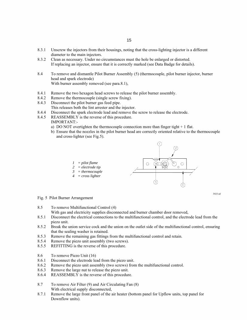
head and spark electrode) With burner assembly removed (see para.8.1), 8.4.1 Remove the two hexagon head screws to release the pilot burner assembly. 8.4.2 Remove the thermocouple (single screw fixing). 8.4.3 Disconnect the pilot burner gas feed pipe. This releases both the lint arrester and the injector. 8.4.4 Disconnect the spark electrode lead and remove the screw to release the electrode. 8.4.5 REASSEMBLY is the reverse of this procedure. IMPORTANT:- a) DO NOT overtighten the thermocouple connection more than finger tight + 1 flat. b) Ensure that the nozzles in the pilot burner head are correctly oriented relative to the thermocouple
and cross-lighter (see Fig.5). 1 = pilot flame 2 = electrode tip 3 = thermocouple 4 = cross lighter 3925.tif Fig. 5 Pilot Burner Arrangement 8.5 To remove Multifunctional Control (4) With gas and electricity supplies disconnected and burner chamber door removed, 8.5.1 Disconnect the electrical connections to the multifunctional control, and the electrode lead from the
piezo unit. 8.5.2 Break the union service cock and the union on the outlet side of the multifunctional control, ensuring
that the sealing washer is retained. 8.5.3 Remove the remaining gas fittings from the multifunctional control and retain. 8.5.4 Remove the piezo unit assembly (two screws). 8.5.5 REFITTING is the reverse of this procedure. 8.6 To remove Piezo Unit (16) 8.6.1 Disconnect the electrode lead from the piezo unit. 8.6.2 Remove the piezo unit assembly (two screws) from the multifunctional control. 8.6.3 Remove the large nut to release the piezo unit. 8.6.4 REASSEMBLY is the reverse of this procedure. 8.7 To remove Air Filter (9) and Air Circulating Fan (8) With electrical supply disconnected, 8.7.1 Remove the large front panel of the air heater (bottom panel for Upflow units, top panel for
Downflow units).
16 8.7.2 Withdraw the filter. IMPORTANT: On downflow models it is necessary to remove a section of internal flue pipe for
access to the Air Circulating Fan. Remove the split pin from the latch on the split collar, disconnect the top section of the flue spigot by pushing the top section
downwards. Remove the screw(s) securing the internal flue spigot to the flue to the flue outlet, and withdraw the internal flue spigot.
8.7.3 Undo two screws on the control box and remove the cover to gain access to the auto transformer (11). 8.7.4 Disconnect the fan connections to the auto transformer, noting their position and withdraw the fan cable. 8.7.5 Undo one screw and release the control box temporarily. 8.7.6 Downflow heaters only: Undo six screws and remove the fan compartment sealing panel. 8.7.7 Undo two screws to release the fan, then ensure that the fan cable is free, and carefully withdraw the fan. 8.7.8 Clear all dust from both impeller and motor, taking care not to disturb the balance of the fan, or
replace as necessary. 8.7.9 REFITTING is in reverse of this procedure. IMPORTANT - DOWNFLOW heaters only - special care must be taken to make a sound
connection when remaking the flue after refitting the Air Circulating Fan, ensuring that the split pin is refitted into the latch on the split collar. Note: On downflow models, ensure that the filter sections are fully engaged, such that the foam strip sits beneath the heater top cross member and forms an effective seal
8.8 To remove 240V-24V Transformer (15) With electrical supply disconnected and burner chamber door removed, 8.8.1 Remove two screws to release the cover panel of the transformer. 8.8.2 Remove the electrical connections to the transformer and note their position. 8.8.3 Undo four screws and remove the transformer. 8.8.4 REFITTING is the reverse of this procedure. Ensure that the washers are in place before replacing the screws. 8.9 To remove auto-transformer (11) With electrical supply disconnected and large front panel of air heater removed, 8.9.1 Undo two screws to release the cover panel. 8.9.2 Undo the single fixing screw to release the transformer assembly. 8.9.3 Disconnect the electrical connections to the transformer, noting their position. 8.9.4 Undo four screws to release the transformer. 8.9.5 REFITTING is the reverse of this procedure. 8.10 To remove Combined Fan and Limit Switch (3) 8.10.1 Remove the screw at the top of the switch (if fitted) and remove the cover. 8.10.2 Disconnect the electrical connection to the switch, noting the colours of the wires. 8.10.3 Remove three fixing screws and withdraw the switch assembly. 8.10.4 REFITTING is the reverse of this procedure. 8.10.5 Check fan and limit switch settings (see para.5.5). 8.11 To remove Spillage switch (17) 8.11.1 Remove two screws to release the spillage switch assembly. 8.11.2 Disconnect the electrical connections to the spillage switch. 8.11.3 REFITTING is the reverse of this procedure. 8.12 Heat Exchanger cleaning With burner assembly removed (see para.8.1), 8.12.1 Remove the heat shield from above the combustion chamber (three screws). 8.12.2 Brush the heat exchanger thoroughly from below. 8.12.3 Replace the heat shield.

17 9. FAULT FINDING IMPORTANT: If an electrical fault occurs after installation of the appliance, preliminary earth
continuity, polarity, and resistance to earth checks should be carried out with a multimeter. On completion of any servicing/ fault-finding task which has required the breaking and remaking of electrical connections, then checks for continuity, polarity and resistance to earth must be repeated.
NOTE: When purging or checking gas supplies, ensure that there is adequate ventilation to the room or cupboard, and that all naked lights are extinguished. SYMPTOM POSSIBLE CAUSE REMEDY (a) Pilot will not light (I) No gas supply to heater. Check for gas at inlet pressure test point on multifunctional control
(II) Gas supply pipe not purged. Purge gas supply pipe in accordance with BS6891.
(III) Pilot orifice restricted. Clear pilot orifice carefully or replace injector (IV) Piezo unit defective Check electrode /lead /igniter. (b) Pilot lights but goes out (I) Connection between Check connection is secure on releasing 'START' thermocouple and multi- button during initial functional control light-up or after normal not secure operation (II) Faulty power unit on Replace multifunctional control multifunctional control (III) Faulty thermocouple Replace thermocouple. (IV) Pilot burner flame of Adjust. insufficient length. (V) Pilot orifice restricted. Replace pilot injector. (c) Main burner lights but (I) Loose electrical connections Check connections for soundness. fan fails to run after to fan side of combined approx. 3 minutes fan/limit switch or to the fan itself. (II) Fan control settings incorrect. Check settings. (III) Faulty fan assembly. Replace, taking care not to damage impellor (IV) Faulty combined fan/limit Replace. switch. (V) Burner pressure not correct. Adjust pressure as necessary. (d) Main burner operating (I) Gas rate or burner pressure Check gas rate and burner intermittently with too high. pressure. fan running. (II) Temperature rise excessive. Adjust fan speed or gas rate accordingly. (III) Air filter or return air Check filter is clean and air path path restricted. is clear. (IV) Excessive number of outlets Open additional outlets. closed.

18 (e) Main burner operating with (I) Gas rate or burner pressure Check gas rate and burner intermittent fan operation. too low. pressure. (II) Fan control settings incorrect. Check settings. (f) Fan runs for excessive (I) Fan control settings incorrect. Check settings. period or operates intermittently after main burner shuts down. (g) Noisy operation (I) Gas pressure too high. Check burner bar pressure. (II) Noisy fan motor. Replace fan motor. (III) Fan speed setting too high. Adjust fan speed. (h) Pilot alight but main (I) Mains electrical supply Check mains supply. burner not igniting not connected to heater. (II) Controls not calling Check that time control (if fitted) for heat and room thermostat are operating correctly. (III) 500mA fuse failed Replace. If failure occurs again, check external room thermostat leads for short to earth. (IV) Loose connection on room Check connections for soundness. thermostat, limit control, multifunctional control lead, time control or transformer. (V) Transformer open circuit. Check with test meter and replace transformer if necessary. (VI) Faulty multifunctional control. Replace multifunctional control. (VII) Faulty control governor Replace multifunctional control. Replace control if necessary. (IX) Faulty room thermostat or Fit temporary loop in heater external wiring room thermostat socket. If heater fires, external circuit or room thermostat is faulty. (X) Spillage switch has Replace spillage switch. operated or is faulty
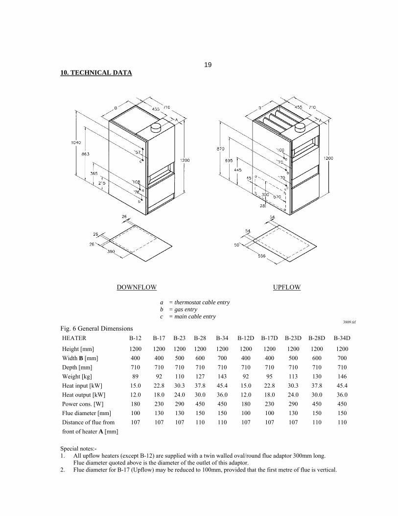
1910. TECHNICAL DATA
DOWNFLOW UPFLOW a = thermostat cable entry b = gas entry c = main cable entry 3809.tif Fig. 6 General Dimensions
HEATER B-12 B-17 B-23 B-28 B-34 B-12D B-17D B-23D B-28D B-34D
Height [mm]
Width B [mm]
Depth [mm]
Weight [kg]
Heat input [kW]
Heat output [kW]
Power cons. [W]
Flue diameter [mm]
Distance of flue from
front of heater A [mm]
1200
400
710
89
15.0
12.0
180
100
107
1200
400
710
92
22.8
18.0
230
130
107
1200
500
710
110
30.3
24.0
290
130
107
1200
600
710
127
37.8
30.0
450
150
110
1200
700
710
143
45.4
36.0
450
150
110
1200
400
710
92
15.0
12.0
180
100
107
1200
400
710
95
22.8
18.0
230
100
107
1200
500
710
113
30.3
24.0
290
130
107
1200
600
710
130
37.8
30.0
450
150
110
1200
700
710
146
45.4
36.0
450
150
110
Special notes:- 1. All upflow heaters (except B-12) are supplied with a twin walled oval/round flue adaptor 300mm long. Flue diameter quoted above is the diameter of the outlet of this adaptor. 2. Flue diameter for B-17 (Upflow) may be reduced to 100mm, provided that the first metre of flue is vertical.
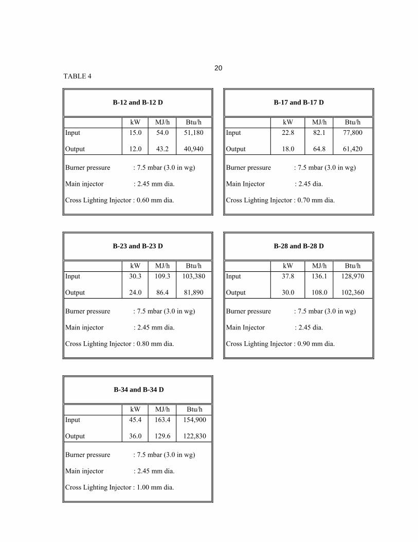
20TABLE 4
B-12 and B-12 D
B-17 and B-17 D
kW MJ/h Btu/h kW MJ/h Btu/h
Input Output
15.0 12.0
54.0 43.2
51,180 40,940
Input Output
22.8 18.0
82.1 64.8
77,800 61,420
Burner pressure : 7.5 mbar (3.0 in wg) Main injector : 2.45 mm dia. Cross Lighting Injector : 0.60 mm dia.
Burner pressure : 7.5 mbar (3.0 in wg) Main Injector : 2.45 dia. Cross Lighting Injector : 0.70 mm dia.
B-23 and B-23 D
B-28 and B-28 D
kW MJ/h Btu/h kW MJ/h Btu/h
Input Output
30.3 24.0
109.3 86.4
103,380 81,890
Input Output
37.8 30.0
136.1 108.0
128,970 102,360
Burner pressure : 7.5 mbar (3.0 in wg) Main injector : 2.45 mm dia. Cross Lighting Injector : 0.80 mm dia.
Burner pressure : 7.5 mbar (3.0 in wg) Main Injector : 2.45 dia. Cross Lighting Injector : 0.90 mm dia.
B-34 and B-34 D
kW MJ/h Btu/h
Input Output
45.4 36.0
163.4 129.6
154,900 122,830
Burner pressure : 7.5 mbar (3.0 in wg) Main injector : 2.45 mm dia. Cross Lighting Injector : 1.00 mm dia.
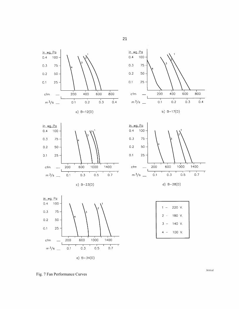
21
3810.tif Fig. 7 Fan Performance Curves
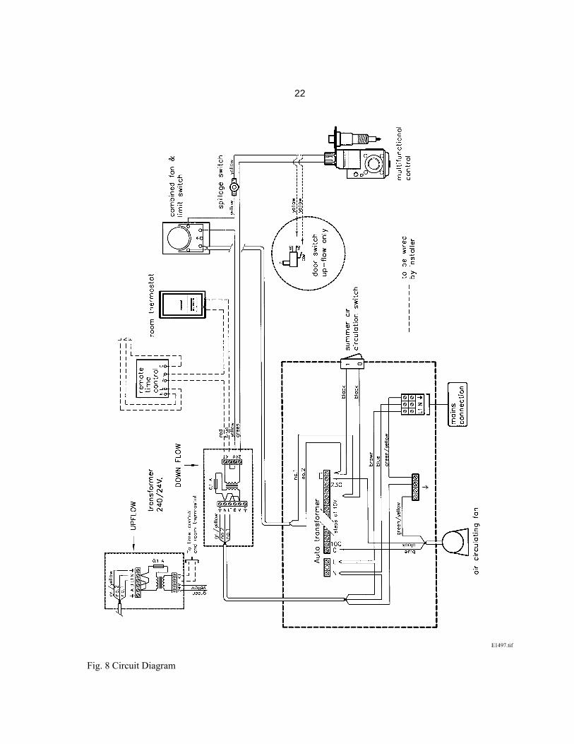
22
E1497.tif Fig. 8 Circuit Diagram
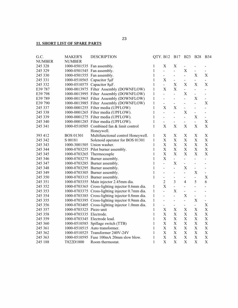
2311. SHORT LIST OF SPARE PARTS G.C. MAKER'S DESCRIPTION QTY. B12 B17 B23 B28 B34 NUMBER NUMBER 245 328 1000-0501535 Fan assembly. 1 X X - - - 245 329 1000-0501545 Fan assembly. 1 - - X - - 245 330 1000-0501555 Fan assembly. 1 - - - X X 245 331 1000-0510565 Capacitor 5μF 1 X - - - - 245 332 1000-0510575 Capacitor 8μF. 1 - X X X X E39 787 1000-0013975 Filter Assembly (DOWNFLOW) 1 X X - - - E39 798 1000-0013995 Filter Assembly (DOWNFLOW) 1 - - X - - E39 789 1000-0013965 Filter Assembly (DOWNFLOW) 1 - - - X - E39 790 1000-0013985 Filter Assembly (DOWNFLOW) 1 - - - - X 245 337 1000-0001255 Filter media (UPFLOW) 1 X X - - - 245 338 1000-0001265 Filter media (UPFLOW). 1 - - X - - 245 339 1000-0001275 Filter media (UPFLOW). 1 - - - X - 245 340 1000-0001285 Filter media (UPFLOW). 1 - - - - X 245 341 1000-0510505 Combined fan & limit control 1 X X X X X Honeywell. 393 412 BOS 01301 Multifunctional control Honeywell. 1 X X X X X 245 342 S 00181 Solenoid operator for BOS 01301 1 X X X X X 245 343 1000-3001505 Union washer. 1 X X X X X 245 344 1000-0703255 Pilot burner assembly. 1 X X X X X 245 345 1000-0703265 Thermocouple 1 X X X X X 245 346 1000-0703275 Burner assembly. 1 X - - - - 245 347 1000-0703285 Burner assembly. 1 - X - - - 245 348 1000-0703295 Burner assembly. 1 - - X - - 245 349 1000-0703305 Burner assembly. 1 - - - X - 245 350 1000-0703315 Burner assembly. 1 - - - - X 245 351 1000-0703355 Main injector 2.45mm dia. 2 3 4 5 6 245 352 1000-0703365 Cross-lighting injector 0.6mm dia. 1 X - - - - 245 353 1000-0703375 Cross-lighting injector 0.7mm dia. 1 - X - - - 245 354 1000-0703385 Cross-lighting injector 0.8mm dia. 1 - - X - - 245 355 1000-0703395 Cross-lighting injector 0.9mm dia. 1 - - - X - 245 356 1000-0703405 Cross-lighting injector 1.0mm dia. 1 - - - - X 245 357 1000-0703325 Piezo unit 1 X X X X X 245 358 1000-0703335 Electrode. 1 X X X X X 245 359 1000-0703345 Electrode lead. 1 X X X X X 245 360 1000-0510585 Spillage switch (TTB) 1 X X X X X 245 361 1000-0510515 Auto transformer. 1 X X X X X 245 362 1000-0510525 Transformer 240V-24V 1 X X X X X 245 363 1000-0510595 Fuse 100mA 20mm slow blow. 1 X X X X X 245 188 T822D1800 Room thermostat. 1 X X X X X
Johnson and Starley prides itself on its ability to supply spare parts quickly and efficiently. If your service engineer indicates a problem in obtaining a spare part, advise him to contact Johnson and Starley Spares Department at the address below. 610394 JOHNSON AND STARLEY LTD., Rhosili Road, Brackmills, Telephone: (01604) 762881 Northampton NN4 7LZ. Telefax: (01604) 767408