b165 r2013 as of 061213 final - abma · american national standards institute 11 west 42nd street...
TRANSCRIPT
[cover] ANSI B165.1 – 20130 Approved American National Standard [Insert ANSI Logo] for Power Tools – Power-Driven Brushing Tools – Safety Requirements for Design, Care and Use American National Standards Institute 11 West 42nd Street New York, New York 10036 [inside front cover] ANSI® B165.1 – 20130 Revision and redesignation ANSI/ABMA B165.1 – 1991 (R201005) American National Standard For Power Tools – Power-Driven Brushing Tools – Safety Requirements for Design, Care and Use Sponsor American Brush Manufacturers Association Approved [Insert Approval Date] American National Standards Institute, Inc. [page] AMERICAN NATIONAL STANDARD Approval of an American National Standard required verification by ANSI that the requirements for due process, consensus, and other criteria for approval have been met by the standards developer. Consensus is established when, in the judgement of the ANSI Board of Standards Review, substantial agreement has been reached by directly and materially affected interests. Substantial
Formatted

agreement means much more than a simple majority, but not necessarily unanimity. Consensus requires that all views and objections be considered, and that a concerted effort be made toward their resolution. The use of American National Standards is completely voluntary; their existence does not in any respect preclude anyone, whether he has approved the standards or not, from manufacturing, marketing, purchasing, or using products, processes, or procedures not conforming to the standards. The American National Standards Institute does not develop standards and will in no circumstances give an interpretation of any American National Standard. Moreover, no person shall have the right or authority to issue an interpretation of an American National Standard in the name of the American National Standards Institute. Requests for interpretations should be addressed to the secretariat or sponsor whose name appears on the title page of this standard. CAUTION NOTICE: This American National Standard may be revised or withdrawn at any time. The procedures of the American National Standards Institute require that action be taken periodically to reaffirm, revise, or withdraw this standard. Purchasers of American National Standards may receive current information on all standards by calling or writing the American National Standards Institute. Published by American Brush Manufacturers Association 736 Main Ave, Suite 7, Durango, CO 81301-54792111 Plum Street, Aurora, IL 60506-3268 Copyright © 20130 by American Brush Manufacturers Association All rights reserved. No part of this publication may be reproduced in any form, in an electronic retrieval system or otherwise, without prior written permission of the publisher. Printed in the United States of America [Insert control number if needed] [page i] CONTENTS Foreword 1 Scope 2 Normative references 3 Definitions 4 Design

5 General machine conditions 6 Mounting of brushes 7 Use of brushes 8 Speeds 9 Handling, storage, and inspection TABLES 1 Minimum spindle (shaft) diameter for brushes of various sizes (in) 1a Minimum spindle (shaft) diameter for brushes of various sizes (mm) 2 Recommended tolerances for arbor hole size (in) 2a Recommended tolerances for arbor hole size (mm) 3 Minimum threaded arbor hole (major diameter) for brushes of various sizes (in) 3a Minimum threaded arbor hole (major diameter) for brushes of various sizes (mm) 24 Test factors for speed test of brushes 35 Conversion table for brush speeds (Surface speed in feet per minute) 53a Conversion table for brush speeds (Surface speed in M per minute) FIGURES 1 Type I, Straight cup brush 2 Type II, Flared cup brush 3 Type I, Straight cup brush with shank 4 Type II, Flared cup brush with shank 5 Type III, Wheel or radial brush 6 Type III, Wheel or radial brush with shank 7 Type IV, End brush 8 Type V, Flared end brush 9 Type VI, Tabular end brush 10 Type VII, Twisted-in wire brush ( or tube cleaning brush) 11 Type VIII, Strip brush 12 Type IX, Class I, cylinder or wide-face brushes
mounted by manufacturer 13 Type IX, Class 2, expendable or unitized cylinder or
wide-face brushes [page ii] Foreword (This foreword is not part of American National Standard B165.1 – 20130 In an endeavor to react with sensitivity to the safety of those associated with power-driven brushes, this standard has as its primary objective the prevention of injuries to those who use them. It would do so by establishing the requirements for the design, care, and use of power-driven brushing tools, excluding those brushing tools constructed with wood, plastic, or composition hubs or cores.
Formatted: Numbered + Level: 1 +Numbering Style: 1, 2, 3, … + Start at: 1 +Alignment: Left + Aligned at: 0" + Tab after: 0.5" + Indent at: 0.5"
Formatted: Numbered + Level: 1 +Numbering Style: 1, 2, 3, … + Start at: 1 +Alignment: Left + Aligned at: 0" + Tab after: 0.5" + Indent at: 0.5"

Information contained in this standard is designed to assist machine operators and their supervisors in maintaining and operating all types of brushing equipment, including portable power tools. The Safety and Standards Committee of the American Brush Manufacturers Association (ABMA) recognizes that it has an obligation to reflect, within this standard, the balanced best interests of the manufacturers and users. To assist in the interpretation of the requirements of this standard, responsibilities have been assigned to brush manufacturers, brushing machine manufacturers, and brush users. This assignment or responsibilities shows that safety must be a cooperative effort shared equally by each of these segments. This standard is a revision of American National Standard Safety Requirements of the Design, Care, and Use of Power-Driven Brushing Tools, ANSI B165.1-1991 (R20105). The original 1991 standard was developed after it was recognized that there was a need for a safety standard for power-driven brushes. To develop the standard, the Industrial Division of ABMA established a Safety and Standards Committee, which worked cooperatively with the Society of Manufacturing Engineers (SME). Prior to publication of the 1991 standard, SME canvassed a large number of interested, concerned, and representative industry associations, government agencies, societies, institutions, foundations, and commissions to ensure the development of a consensus. After approval, the Standard was published by SME in 1991 with the co-sponsorship of the ABMA and the cooperative help of the American National Standards Institute (ANSI). During the past threefive years, the 20105 standard served the best interests of those most affected or influenced by its use. In accordance with the revisions of the American National Standards Institute’s five-year periodic review procedure, this Standard has been reviewed, revised, and updated through the Canvass Method. The standard was reaffirmed in 2000, and revised in 2005 and 2010. Suggestions for improvement of the standard are welcomed. They should be sent to the American Brush Manufacturers Association, 736 Main Ave, Suite 7, Durango, CO 81301-54792111 Plum Street, Aurora, IL 60506-3268. The following organizations recognized as having an interest in the standardization of power-driven brushing tools were contacted prior to the approval of this standard. Inclusion in this list does not necessarily imply that the organization concurred with the submittal of the proposed standard to ANSI. Alliance of American Insurers American Association of Industrial Management American College of Occupational and Environmental Medicine American Dental Association American Federation of Labor and Congress of Industrial Organizations (AFL-CIO) American Foundry Society American Insurance Association

American Iron and Steel Institute American Petroleum Institute American Society for Testing and Materials American Society of Safety Engineers American Supply and Machinery Manufacturers Association American Textile Machinery Association American Welding Society Association for Manufacturing Technology Canadian Vehicle Manufacturers Association CNA Insurance Consumer Product Safety Commission Consumer Testing Laboratories, Inc. European Brush Manufacturers Association (FEIBP) FM Global Gallagher Bassett Services, Inc Gases and Welding Distributors Association GE ERC Industrial Supply Association International Association of Ironworkers International Association of Machinists International Safety Equipment Association National Association for Surface Refinishing National Association of Dental Laboratories National Hardwood Lumber Association National Restaurant Association National Safety Council National Welding Supply Association Power Tool Institute Society of Automotive Engineers Society of Manufacturing Engineers Society of the Plastics Industry Triodyne Incorporated Underwriters Laboratories Unified Abrasives Manufacturers Association Union of Needletrades, Industrial and Textile Employees United Abrasives Manufacturers Association United Autoworkers Union United Brotherhood of Carpenters and Joiners of America United Steelworkers of America U.S. Department of Labor – OSHA U.S. General Services Administration

Explanation of Standard Format This standard uses a two-column format to provide both specific requirements and supporting information. The left column, designated “Standard Requirements” is confined solely to these requirements and is printed in bold type. Where supporting photographs or sketches are required, they are designated as “figures”. The right column, designated “Explanatory Information” contains only information to clarify the standard. This is not part of the standard. Where supplementary photographs or sketches are required, they are designated as “illustrations”. The information contained in E4.3 Illustration 2 is not part of this American National Standard (ANS) and has not been processed in accordance with ANSI’s requirements for an ANS. As such, Illustration 2 may contain material that has not been subjected to public review or a consensus process. In addition, it does not contain requirements necessary for conformance to the standard. Operating rules (safe practices) are not included in either column unless they are of such nature as to be vital safety requirements, equal in weight to other requirements or guides to assist in compliance with the standard.

American National Standard for Power Tools – Power-Driven Brushing Tools – Safety Requirements for Design, Care, and Use Standard Requirements 1 Scope The purpose of this standard is to establish the rules and specifications for safety that apply in the design, use, and care of power-driven brushing tools. It includes specifications for shanks, adapters, flanges, collets, chucks, and safety guards and rules for the proper storage, handling, mounting, and use of brushes. It embraces configurations of brushing tools whose functional performance is accomplished by power-driven operation. Covered are brushing tools whose brushing elements are made up of ferrous wire, nonferrous wire, plastic, abrasive filaments, vegetable fibers, animal hair, or other materials, and brushes fabricated with any combination of such elements. Brushing tools whose primary function is vehicle or train washing, carpet sweeping, dental hygiene, floor maintenance, sewer cleaning, street sweeping, and brushing tools manufactured in accordance with other applicable American National Standards are not covered. 2 Normative references The following standards contain provisions which, through reference in this text, constitute provisions of this American National Standard. At the time of publication, the editions indicated were valid. All standards are subject to revision, and parties to agreements based on this American National Standard are encouraged to investigate the possibility of applying the most recent editions of the standards indicated below. ANSI B7.1-2011, Safety requirements for the use, care, and protection of abrasive wheels ANSI Z88.2, Practices for respiratory protection

ANSI/ISEA Z87.1-2010, Practice for occupational and educational eye and face protection ANSI/UL 60745, Safety standard for stationary and fixed electric tools ANSI/UL 987, Safety standard for stationary and fixed electric tools Z88.2, Practices for respiratory protection
3 Definitions 3.1 General definitions 3.1.1 brush: For brevity in this standard, used interchangeable with “brushing tool,” “power driven brushing tool,” or “power-driven brush.” 3.1.2 shall and should: The word “shall” where used is to be understood as mandatory, and “should” as advisory. 3.1.3 revolutions per minute (rpm): The number of complete turns that a brush makes in one minute. 3.1.4 surface feet per minute (sfpm): The distance in feet traveled by any spot on the peripheral surface of a brush in one minute.
3.1416 x diameter in inches x rpm sfpm = 12 or: 0.262 x diameter in inches x rpm for a very close approximation 3.1.4a surface meters per minute (smpm): The distance in meters traveled by any spot on the peripheral surface of a brush in one minute. 3.1416 x diameter in millimeters x rpm smpm = 1000 or: 0.003 x diameter in millimeters x rpm for a very close approximation 3.1.5 the brush manufacturer: Any individual, partnership, corporation, or other form of enterprise that manufacturers or assembles any kind of power-driven brushing tools. 3.1.6 the brush machine or power tool builder:
- Any individual, partnership, corporation, or other form of enterprise that is engaged in the development, or manufacture, or both, or any type of machine or power tool that uses power-driven brushing tools.
- One who converts, changes, or otherwise alters the original design of such machines or power tools.
3.1.7 the user: Any individual, partnership, corporation, or other form of enterprise that uses any kind of power-driven brushing tools or brush machines. 3.1.8 maximum safe free speed (MSFS or max. SFS): Synonymous with maximum safe rpm (free rotation or no-load speed). The maximum speed at which the brush shall be rotated with no work applied (spinning free) to ensure safe operation. All brush manufacturers have the responsibility of determining the MSFS for their products. A recognized criterion for establishing this value for each brush is described in 8.3. 3.1.9 brush face: The surface of the brush that does the brushing as viewed from the ends of the filaments. 3.1.9.1 face width: The axial dimension at the outside diameter of a brush when it is measured in its static condition. 3.1.9.2 operating face width: The width of the face of the brush, measured at operating speed. 3.1.10 fill or fill material: The filaments that do the brushing in a brush. Fill material can be ferrous or nonferrous wire, abrasive loaded plastic, plastic, composites, vegetable fiber, animal hair, or other materials. Sometimes the fill is a combination of two or more different fill materials, such as wire, tampico, horsehair, plastic, vegetable fiber, and pig bristle. 3.1.10.1 crimped plastic fill material: Synthetic fill material whose linear configuration is not straight or level, but is corrugated in appearance from having been passed through gears or other devices. 3.1.10.2 abrasive loaded plastic fill materials: Synthetic fill material made of plastic monofilaments that have abrasive grit homogeneously dispersed throughout. 3.1.10.3 straight or level plastic fill material: Synthetic fill material that is straight before being used in a brush or before being formed into a tuft or other configuration as part of a brush. 3.1.10.4 vegetable fiber fill material: An end product resulting from the processing of the fibrous part of the leaf or root of various types of plants and trees. Typical fibers are tampico, palmyra, bassine, and palmetto. 3.1.10.5 hair fill material: The hair of any animal except a pig, hog, or boar. Whalebone and feathers are not construed to be hair. 3.1.10.6 bristle fill material: the hair of a pig, hog, or boar. 3.1.11 brush flexibility: The brush’s capability to conform to irregular or contoured surfaces are

measured by filament deflection. 3.1.12 bonded brushes (also, elastomerically encapsulated brushes): Have elastomer material molded into them unitizing the fill material. 3.1.13 crimped wire: Wire that has been passed through gears or other devices to impart a corrugated appearance to the wire. 3.1.14 straight wire: Wire that was straight before being used in a brush or before being formed into a tuft or other configuration as part of a brush. 3.1.15 twisted tuft or knot: A group of straight wires of equal length that are passed through or around a retaining member, bent into a U-shape, then twisted together to form a single tuft. The helix angle, or angle of twist of a tuft is the angle through which a radial section of a group of wires deflects from its normal position when the wires are subjected to a predetermined twisting torque. The helix angle is a variable, contingent upon the type of wire, the diameter, and the size of the tuft. 3.1.16 shank: Male extension and driving means (usually of an end, wheel, or cup brush) capable of being gripped in a chucking device or collet of proper size. 3.1.17 arbor adapter: Device used to reduce the size of an arbor hole in a brush. Frequently, an adapter is a concentric ring with or without a shoulder. 3.1.18 density: The number of filament ends per given area of brush face. 3.1.19 trim length: Dimension of fill material extending from beyond the retaining member, face plate, or bridle (visible length of filament). 3.1.20 safety guard: Enclosure designed to contain any filaments, or any particles removed by brushing, that might be thrown from the brush or by the brush while it is rotating. Guards shall be placed where necessary, except in the open area of operation to allow access to the work. 3.1.21 safety shield: Fixed or adjustable transparent visor or eye shield that is connected to the brushing machine, which provides additional safety for the operators while permitting them to visually observe the brushing being accomplished. In addition to fixed or adjustable transparent visors or eye shields that are attached to a machine, brush operators and others in the area of the brushing operation shall wear safety goggles, full face shields over safety glasses with side shields, or other forms of personal eye protection as described in ANSI Z87.1. 3.1.22 barrier: any partition, wall, or separate brushing booth that provides protection to the operator and/or other personnel in the area. 3.1.23 arbor hole bushing: Centering device placed in an arbor hole to reduce its size. Tubular bushings are frequently used for this purpose and are used in the same way as adapters without a shoulder.

3.1.24 bridle: Brush component used to control or restrain flare on cup or end brushes. 3.2 Definitions of brush configurations. Elastomerically encapsulated brushes of the
following types and classes shall be subject to the same regulations as the base brush. 3.2.1 Type I, straight cup brushes: As shown in Figure 1, type I brushes are brushes with a cup configuration and straight sides that are parallel to the axis of the brush. Dimensions shall include the outside diameter, inside diameter, trim length, overall height, face width, and arbor hole diameter.
- Class 1: crimped wire, abrasive loaded plastic, plastic, fiber, or hair fill material: As shown in Figure 1(a), class 1 brushes with crimped wire, abrasive loaded plastic, or plastic fill material have additional dimensions such as wire or plastic diameter, crimp amplitude, and crimp wave length. Specifications include the appropriate chemical and physical attributes of the fill material. When brushes are furnished with fiber or hair fill material, the type of quality of the material shall be specified.
- Class 2: Twisted tuft or knot fill material: As shown in Figure 1(b), class 2 brushes with a twisted tuft or knot have additional dimensions such as wire diameter and number of rows or tufts. Specifications include the appropriate chemical and physical attributes of the fill material. Helix angle or twist configuration of tufts and length of twist may be described.
3.2.2 Type II, flared cup brushes: As shown in Figure 2, type II brushes are brushes with a cup configuration that have flared cups with the included angle of the cup being a variable depending upon the application. Dimensions shall include outside diameter, inside diameter, trim length, overall heights, face width, and arbor hole diameter.
- Class 1: crimped wire, abrasive loaded plastic, plastic fiber, or hair fill material: As shown in Figure 2(a), class 1 brushes with crimped wire, abrasive loaded plastic or plastic fill material have additional dimensions such as wire or plastic diameter, crimp amplitude, and crimp wave length. Specifications include the appropriate chemical and physical attributes of the fill material. When brushes are furnished with fiber or hair fill material, the type and quality of the material shall be specified.
- Class 2: twisted tuft or knot fill material: As shown in Figure 2(b), class 2 brushes with a twisted tuft or knot have additional dimensions such as wire diameter and number of rows or tufts. Specifications include the appropriate chemical and physical attributes of the fill material. Helix angle or twist configuration of tufts and lengths of twist may be described.
3.2.3 cup brush with shank: Type I straight cup brushes, both class 1 and class 2, can be furnished with a shank as shown in Figures 3(a) and 3(b). Dimensions and specifications shall be the same as in 3.2.1, except arbor hole dimensions are not applicable. Additional dimensions shall include diameter and length of shank.

Type II flared cup brushes, both class 1 and class 2, can be furnished with a shank as shown in Figures 4(a) and 4(b). Dimensions and specifications shall be the same as in 3.2.2, except arbor hole dimensions are not applicable. Additional dimensions shall include diameter and length of shank. 3.2.4 Type III, wheel or radial brush: As shown in Figure 5, type III brushes are circular brushes with a wheel configuration. Dimensions shall include diameter, trim length, face width, and arbor hole dimensions. Radial brushes whose length exceeds their diameter are called cylinder or wide-face brushes (see 3.2.11).
- Class 1: crimped wire, abrasive loaded plastic, plastic, fiber, or hair fill material: As shown in Figure 5(a) class 1 brushes with crimped wire, abrasive loaded plastic, or plastic fill material have additional dimensions such as wire or plastic diameters, crimp amplitude, and crimp wave length. Specifications include appropriate chemical and physical attributes of the fill material. When brushes are furnished with fiber or hair fill material, the type and quality of the material shall be specified.
- Class 2: twisted tuft or knot: As shown in Figure 5(b), class 2 brushes with a twisted tuft or knot have additional dimensions such as wire diameter and number of rows or tufts. Specifications include the appropriate chemical and physical attributes of the fill material. Helix angle or twist configuration of tufts and length of twist may be described.
3.2.5 wheel or radial brush with shank: Type III wheel brushes, both class 1 and class 2, can be furnished with a shank as shown in Figures 6(a) and 6(b). Dimensions and specifications shall be the same as 3.2.4, except that arbor hole dimensions are not applicable. Additional dimensions shall include diameter and length of shank. 3.2.6 Type IV, end brush: As shown in Figure 7, type IV brushes have an end brush configuration with the fill material protruding from one end of the driving component. They generally have a permanently attached shank. The fill material is oriented so that its length is parallel to the axis of the brush. Dimensions shall include face outside diameter, trim length, shank diameter, shank length, overall length, and cup diameter.
- Class 1: end brush with crimped wire, abrasive loaded plastic, plastic, fiber, or hair fill material. There are three styles of class 2 end brushes (see Figure 7(a)). They all have additional dimensions that include wire, abrasive loaded plastic, or plastic diameter, crimp amplitude, and crimp wave length. Specifications include appropriate chemical and physical attributes of the fill material. When brushes are furnished with fiber or hair fill material, the type and quality of the material shall be specified.
Elastomerically encapsulated brushes of this class shall be subject to the same regulations as the base brush.

- Style A, solid filled end brush: Style A brushes have the cup end filled so that the brush presents a continuous face. - Style B, hollow center end brush: Style B brushes are identical to style A brushes in every respect, except that the face has a circular void centrally located on the face of the brush. These brushes have the additional dimensions of face inside diameter. - Style C, pilot end brush: Style C brushes are identical to style A brushes in every respect, except that a pilot protrudes from the central part of the face. It has the additional dimensions of the diameter, center length, and radius of the pilot. The chemical and physical properties of pilot material shall be identified.
- Class 2: end brush with twisted tuft or knot, hollow center: Class 2 end brushes (see
Figure 7(b)) with a twisted tuft or knot have additional dimensions that include wire diameter, number of tufts, inside diameter, and face outside diameter. Specifications should include appropriate chemical and physical attributes. Helix angle or twist configuration of tufts and length of twist may be described.
3.2.7 Type V, flared end brush: As shown in Figure 8, type V flared end brushes have a self- contained shank. The fill material that protrudes from the retaining cup is flared into a circular pattern, with the filaments being oriented into a radial configuration. Dimensions shall include flared diameter, face width, cup diameter, shank diameter, shank length, overall length, filament diameter, crimp amplitude, and crimp wave length. Specifications include appropriate chemical and physical attributes of wire or other fill materials. 3.2.8 Type VI, tubular end brush: As shown in Figure 9, type VI tubular end brushes are constructed both with and without shank extension. The fill wire, abrasive-loaded plastic, plastic, or other fill material is oriented so that its length is parallel to the axis of the brush. Dimensions shall include outside diameter, trim length, and overall length. The brushes can be filled with either straight or crimped fill material. The diameter of the wire, abrasive-loaded plastic, or plastic fill material shall be specified. If crimped wire, abrasive loaded plastic, or plastic is used, the dimensions of crimp wave length and crimp amplitude shall be specified. Specifications include appropriate chemical and physical attributes of the fill material. When brushes are furnished with fiber or hair fill material, the type and quality of the material shall be specified. Elastomerically encapsulated brushes of this class shall be subject to the same regulations as the base brush. If the tubular end brush contains a shank, the diameter and the length of the shank shall be specified. 3.2.9 Type VII, twisted-in wire brush (or tube cleaning brush): As shown in Figure 10, type VII twisted-in wire brushes are made by twisting the fill material between two or more retaining stem wires. This construction places each filament in a radial position in which the total mass of

fill material is helical or spiral in configuration. Specifications include type of fill, outside diameter and length of brush part, number of stem wires, stem length, and stem diameter. Either straight or crimped fill material can be used. The size of the fill material shall be specified. If crimped material is used, the dimensions of crimp wave length and the crimp amplitude shall be specified. Specifications include appropriate chemical and physical attributes of both the fill materials and the stem wire. If the twisted-in wire brush has a shank or extension affixed to the stem, the diameter of the shank or extensions shall be specified. If the shank is threaded, the size and length of the thread is specified. Elastomerically encapsulated brushes of this class shall be subject to the same regulations as the base brush. 3.2.10 Type VIII, strip brush: As shown in Figure 11, type VIII strip brushes are manufactured in a continuous strip form and subsequently cut to the required finish length. In addition to their straight configuration (shown in Figure 11), strip brushes may also be helically wound around the outside of an arbor for use as wide-face rotary brushes (see the coil-wound strip in Figures 12 and 13). Strip brushes are commonly manufactured by roll forming a metal channel and pressing the fill material into the channel in a hairpin configuration. A retaining member runs the entire length of the strip to ensure retention of the fill material. 3.2.11 Type IX, cylinder or wide-face brushes: As shown in Figure 12, type IX cylinder brushes are either directly mounted on reusable arbors by the brush manufacturer or assembled as replacement elements by the user. The mandrel on which the brushes are mounted can be manufactured by either the brush manufacturer, the brush machine builder, or the user. The specifications of the arbor shall be determined by the brush machine builder. The specifications may be modified by the brush manufacturer if the modifications do not preclude the arbor being used in the machine for which it was designed. The dimensions for the brushes shall include outside diameter, inside diameter, face width, and trim length.
- Class 1: Cylinder or wide-face brushes that are mounted by brush manufacturer: Class 1 brushes are either sectional built-up face brushes or strip brushes. Many modifications of each of them are produced and many are customized for particular applications of users. Figure 12 shows several types of sectional built-up face and strip cylinder brushes.
The specifications frequently include provisions for brushes in which coolant or other liquids are pumped through the face of the brush. - Style A, Sectional built-up face:

- Crimped fill material: Specifications include fill diameter, crimp
amplitude, and crimp wave length and appropriate chemical and physical attributes of the fill material.
- Twisted tuft or knot fill material: Specifications include wire diameter and the number of rows of tufts, helix angle (twist configuration, length of twist, and tuft concentration). Specifications include appropriate chemical and physical attributes of the fill material.
- Nonmetallic fill material: Specifications shall include type of fill and size of filaments.
- Style B, strip: Strip brushes can be inserted in mounting clips or otherwise
anchored on the permanent (reusable) arbors so that the density of the fill can range from very light to very heavy.
Dimensions shall include height and width of metal retaining device, overall height of strip, number of strips, description of the fill material, and helix (spiral) angle of the strip.
- Straight strip brushes with wire or nonmetallic fill material: Straight strip brushes are fastened parallel to the axis of the hub. Specifications include wire diameter, crimp amplitude, crimp wave length, and appropriate chemical and physical properties of the wire fill material, type of material if nonmetallic, and diameter of filaments, where appropriate.
- Helix strip brushes: Helix strip brushes can be assembled in a
helically disposed arrangement with the individual strip brushes positioned in a longitudinal direction.
- Coil-wound strip brushes: Strip brushes can be wound
circumferentially around the arbor with either a long lead (pitch) or a closely wound lead (pitch) to provide open or dense construction.
- Class 2: Expendable brushes, unitized brushes, or both: Like class 1 brushes, class 2
brushes are either sectional built-up face brushes or strip brushes. These brushes can be manufactured either by factory assembly directly onto the user’s shaft or as a cartridge-type unit that is made for later assembly on the user’s arbor at the time of need. Examples of these brushes are provided in Figure 13.
- Style A, Sectional built-up face:
- Crimped fill material: Specifications include type of fill material, fill
diameter, crimp amplitude, crimp wave length, and appropriate chemical and physical attributes of fill material.

- Twisted tuft or knot fill material: Specifications include wire diameter and number of rows of tufts, helix angle (twist configuration), length of twist, tuft concentration, and appropriate chemical and physical attributes of wire fill material.
- Nonmetallic fill material: Specifications shall include type of fill and
size of filaments.
- Style B, strip: Strip brushes can be inserted in mounting clips on the permanent (reusable) arbors or anchored to cartridges that can be mounted on the user’s arbors. The mounting method allows a variation in the density of the brush from very light to very heavy. Dimensions shall include height and width of metal retaining device, overall height of strip, number of strips, description of the fill material, and helix angle of the strip, where applicable.
- Straight strip brushes with wire fill material: Straight strip brushes are
fastened parallel to the axis off the hub. Specifications include wire diameter, crimp amplitude, crimp wave length, and appropriate chemical and physical properties of the wire fill material.
- Straight strip brushes with nonmetallic fill material: In addition to the
specifications for straight strip brushes with wire fill material, specifications for strip brushes with nonmetallic fill material also include the type of material and the diameter of filaments, where appropriate.
- Helix strip brushes: Helix strip brushes can be assembled in a
helically disposed arrangement with the individual strip brushes positioned in a longitudinal direction.
- Coil-wound strip brushes: Strip brushes can be wound
circumferentially around the arbor with either a long lead (pitch) or a closely wound lead (pitch) to provide open or dense construction.
4 Design 4.1 Manufacture of brushes The brush manufacturer shall be responsible for the design of brushes produced and shall apply the principles of strength of materials to ensure that satisfactory materials are utilized and adequate proportions obtained to resist functional forces produced by centrifugal forces or impact. 4.2 Material

All components of the brush shall be of such design as to transmit the driving torque from the spindle to the brush periphery. They shall be constructed in such a manner as to ensure an even distribution of fill material throughout the brush so that good balance can be attained. Adequate provision for filament retention shall be made. The fill material shall not be burned, broken, or otherwise affected by any assembly operations so as to make it unsafe. 4.3 Marking When sufficient surface space is available, each brush shall be marked in a permanent manner to show the maximum safe free speed in revolutions per minute; the brush shall also carry the words, “Wear eye protection,” when sufficient space is available. The manufacturer’s name or trademark shall also be included. If only the trademark is used, it shall be of such known character that the source of manufacture can be readily determined. Brush manufacturers may omit their names or trademarks on a brush sold to a distributor or another brush manufacturer whose own name or trademark will appear on the brush. In such cases (known as “private branding”), the brush manufacturer and the private brander shall mutually determine which of them is to do the marking. It shall, however, be the responsibility of the private brander to see that the brush is not transferred to the user without being permanently marked with identifying markings. 4.4 Balance Brushes that are out of balance set up vibrations that can result in marred work surfaces or machine damage, and that can also cause stress that could result in brush failure. A brush that vibrates in service shall not be used (see 4.1). 4.5 Adapters If arbor adapters are used in a brush to reduce it to the correct arbor hole size, they shall seat properly in the brush to maintain alignment and balance. 5 General machine conditions 5.1 Machine design and maintenance It shall be the brush machine builder’s responsibility to indicate the maximum rpm of the machine and the size of the brush to be used on the machine based on the requirements for guarding the machine as described in ANSI B7.1, ANSI/UL 60745, or ANSI/UL 987, as applicable. It shall be the user’s responsibility to maintain the machines in safe operating condition. 5.2 Safety Guards
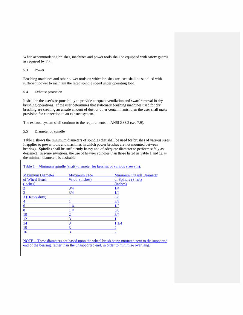
When accommodating brushes, machines and power tools shall be equipped with safety guards as required by 7.7. 5.3 Power Brushing machines and other power tools on which brushes are used shall be supplied with sufficient power to maintain the rated spindle speed under operating load. 5.4 Exhaust provision It shall be the user’s responsibility to provide adequate ventilation and swarf removal in dry brushing operations. If the user determines that stationary brushing machines used for dry brushing are creating an unsafe amount of dust or other contaminants, then the user shall make provision for connection to an exhaust system. The exhaust system shall conform to the requirements in ANSI Z88.2 (see 7.9). 5.5 Diameter of spindle Table 1 shows the minimum diameters of spindles that shall be used for brushes of various sizes. It applies to power tools and machines in which power brushes are not mounted between bearings. Spindles shall be sufficiently heavy and of adequate diameter to perform safely as designed. In some situations, the use of heavier spindles than those listed in Table 1 and 1a as the minimal diameters is desirable. Table 1 – Minimum spindle (shaft) diameter for brushes of various sizes (in). Maximum Diameter Maximum Face Minimum Outside Diameter of Wheel Brush Width (inches) of Spindle (Shaft) (inches) (inches) 2 3/4 1/4 3 3/4 1/4 3 (Heavy duty) 1 3/8 4 1 3/8 6 1 ¼ 1/2 8 1 ¼ 5/8 10 2 3/4 12 3 1 14 3 1 1/4 15 3 2 16 3 2 NOTE – These diameters are based upon the wheel brush being mounted next to the supported end of the bearing, rather than the unsupported end, in order to minimize overhang.

Table 1a – Minimum spindle (shaft) diameter for brushes of various sizes (mm). Maximum Outside Maximum Face Maximum Outside Diameter Diameter of Width (mm) of Spindle (Shaft) Wheel Brush (mm) (mm) 50 20 6mm 75 20 6mm 75HD 25 10mm 100 25 10mm 150 32 13mm 200 32 16mm 250 50 19mm 300 75 25mm 350 75 32mm 380 75 32mm 400 75 50mm NOTE – These diameters are based upon the wheel brush being mounted next to the supported end of the bearing, rather than the unsupported end, in order to minimize overhang. 5.6 Work rests On single- or double-end pedestal machines used for brushing, work rests shall be used, where applicable, to support the work. They shall be of rigid construction and designed to be adjustable to compensate for brush wear. Work rests shall be kept adjusted close to the brush with a maximum opening of 1/8 inch (3.175 millimeter) to prevent the work from being jammed between the brush and the work rest, as such jamming may cause failure of the brush or injury to the operator. The work rest shall be securely clamped after each adjustment. The adjustment shall be made with the power source off, with the machine in zero mechanical state, and with no possibility of the brush rotating. 5.7 Limiting brush diameter Non-portable brushing machines shall be provided with a means of limiting the diameter of the brush to be mounted. On variable-speed machines, the speed-shifting device shall be connected with an adjustable guard or other diameter-limiting device to prevent the mounting of a brush that might run at higher than the recommended surface speed or rated rpm. 5.8 Direction of machine spindle thread If brushes are secured by means of a spindle nut, the direction of the thread in relation to the direction of the rotation shall cause the nut to tighten as the spindle revolves.

5.9 Length of machine spindle thread If brushes are mounted by means of a spindle nut and flanges, two conditions shall be maintained: -Spindles shall be of sufficient length to allow a full nut mounting;
-The threaded portion shall be sufficient so that the threading will extend well inside the flange but not more than halfway within the arbor hole of the brush.
5.10 Spindle, drive arbor, and arbor hole size The size of the arbor hole of the brush shall be such that the brush will slip-fit on the drive spindle or drive arbor and shall remain within this fit class under all operating temperatures. The brush spindle or drive arbor shall not be made larger than the nominal dimension size. The arbor hole of the brush shall be made oversize from the nominal dimension by the brush manufacturer by an amount necessary to ensure a free fit but not a loose fit. When the arbor hole is changed by the manufacturer or user, the recommended tolerances for the arbor hole shall be as follows in Tables 2 and 2a below: Table 2 – Recommended tolerances for arbor hole size (in) Arbor hole Minimum Maximum Arbor hole Minimum Maximum Size (mm) Tolerance Tolerance Size (in) Tolerance Tolerance (mm) (mm) (mm) (in) (in) (in) Under 15.9 +.025 +.127 Under 5/8 +0.001 +0.005 15.9-50.8 +.025 +.152 5/8 – 2 +0.001 +0.006 50.8-152.4 +.051 +.178 2 – 6 +0.002 +0.007 152.4-304.8 +.076 +.305 6 – 12 +0.003 +0.012 Table 2a – Recommended tolerances for arbor hole size (mm) Arbor hole Minimum Maximum Size (mm) Tolerance Tolerance (mm) (mm) (mm) Under 15.9 +.025 +.127 15.9-50.8 +.025 +.152 50.8-152.4 +.051 +.178 152.4-304.8 +.076 +.305 The minimum arbor hole to be used for each class of brush shall be the smallest size offered for sale by the individual brush manufacturer. The minimum size offered shall be compatible with the service conditions for which the brush is intended. Where the user reduces the arbor hole by use of a bushing, or otherwise, the minimum arbor size, the maximum brush face length, and the

maximum overhang length shall be in accordance with the recommendations of the brush manufacturer. The user shall ensure that the size and shape of the arbor hole of the brush will not cause the hole to catch the threads during mounting, which would cause the brush to be eccentric or would prevent proper axial compression and tightening. 5.11 Threaded arbor hole brushes Machines on which threaded hole brushes are mounted shall be designed with spindles that are threaded so as to allow the brush to be screwed firmly and flat against the back flange, with a minimum engaged thread length of 1X diameter for steel and 2X diameter for aluminum components. See Table 3 and Table 3a below for minimum threaded arbor hole diameters that shall be used for brushes of various sizes. Tables 3 and 3A list the recommended minimum threaded arbor diameter sizes with a minimum shaft yield strength of 50,000 PSI for various brushes diameters. Multiple factors including RPM, dynamic loads along with brush and equipment configuration must always be considered when mating a brush to a power tool or any custom designed equipment to drive power brushes. For any non-recommended arbor size it is critical to consult your brush and equipment designer or manufacture prior to brush application. The back of the flange shall be flat, securely fastened, and square to the spindle axis. The fixed back flange shall be of sufficient diameter to ensure proper support to the brush. The direction of the thread shall be such that, in order to be removed, the brush must be turned in the direction of rotation. If threaded hole brushes have blind holes, the length of the spindle shall be in relationship to the depth of the hole such that the end of the spindle will not touch the bottom of the brush hole. Table 3 – Minimum threaded arbor hole (major diameter) for brushes of various sizes (in) Maximum outside diameter of wheel brush (in) Minimum threaded arbor hole
(major diameter) (in)
Up to and including 4 Greater than 4 and up to and including 5 Greater than 5 and up to and including 8 Greater than 8
3/8 1/2 5/8 Do not use a threaded hole
Table 3a – Minimum threaded arbor hole (major diameter) for brushes of various sizes (mm) Maximum outside diameter of wheel brush
(mm) Minimum threaded arbor hole
(major diameter) (mm)
Up to and including 100 Greater than 100 and up to and including 125 Greater than 125 and up to and including 175 Greater than 175
M10M12 M14 Do not use a threaded hole
Formatted: Not Highlight
Formatted Table

5.12 Solid shanks for brushes to be used with collets and chucks These requirements do not apply to shanks on twisted-in wire brushes. Shank diameters shall be of nominal size, expressed in decimal form with a tolerance not exceeding +0.000 inch -–0.005 inch or +0.000 millimeters –0.127 millimeters. The geometric configuration of shank-type brushes or shank-type arbors shall include generous fillets where the diameters of the parts increase and where stress concentration is likely to occur. Where extension of a brush shank or arbor shank is needed to obtain additional reach, a special tool extension shall be used. This tool or brush holder shall be of such dimension and geometrical shape as to withstand the brushing pressure used, and avoid deflection that causes vibrations that can become dangerous. The brushes shall be test-run under guarded or shielded conditions for 30 seconds after each mounting or remounting to ensure that they are properly gripped in the chuck or collet. Shank brushes used with an extension shall only be rotated when contained within the cavity or interior to be abraded. The power shall be turned off and the rotation of the brush stopped before the brush is extracted from the part. Construction details of user-made or user-selected extension holders shall meet the foregoing requirements. Brushes used with shanks (types I through VI) are hazardous when chucked with the axis of the brush not parallel to, and concentric with, the axis of the chuck; or not tightened in the chuck tightly enough to drive it under load; or when used at speeds higher than those recommended by the brush manufacturer; or when the shank has not been inserted to the maximum depth with the minimum overhang. 6 Mounting of brushes 6.1 Inspection Immediately before mounting, all brushes shall be closely inspected according to 7.2 and 7.4 to make sure they are suitable for use.
6.2 Arbor size Brushes shall fit freely on the spindle and remain free under all brushing conditions. If, however, the spindle is worn or undersize, the brush shall not be mounted, since off-center mounting will cause the brush to be out of balance. If the spindle is oversized, the brush shall not be forced on, since damage to the brush and the machine is almost unavoidable. A sufficient clearance between the arbor hole of the brush and the machine spindle (or adapters) shall be maintained to avoid problems in mounting or removal caused by spindle expansion from temperature change.

To accomplish this, the machine spindle and the brush arbor hole shall be made in accordance with the requirements of 5.10. 6.3 Surface condition All contact surfaces of brushes, flanges, and adapters shall be flat and free of foreign matter that could result in uneven pressure. Flanges, adapters, and brushes shall be checked periodically to see that they are not distorted or burred so as to cause improper functioning. 6.4 Bushing When a bushing is used in the arbor hole of the brush, it shall center the brush and ensure that the brush, rather than the bushing, will be gripped by the machine spindle shoulder or machine flange. The driving of the brush shall be accomplished positively through the back or center of the brush rather than through the bushing to ensure proper anchoring and driving of the brush. A bushing should never be used that will violate 5.5, Table 1 or 5.5, Table 1a. 6.5 Multiple-section brushes mounted on a common arbor When more than one brush is mounted on a common arbor, they shall have equal arbor hole diameters. They shall be of a type manufactured for multiple mounting and so designated by the brush manufacturer. 6.6 End nut The spindle end nut shall be tightened only enough to drive the brush and prevent slippage, and shall be used only if the direction of the threads (right hand or left hand) is such that the nut tends to tighten when rotated and under load. Spindle end nuts with locking devices such as set screws shall be used under heavy duty conditions or where brush rotation reversal or stopping by brake action is practiced. 6.7 Mounting of shank-type brushes All shank-type brushes of types I through V, and type VI brushes with and without shank, shall be firmly tightened in a chuck or collet so that no slippage can occur. The shank shall be inserted into the chuck or collet as far as possible on the uniform diameter of the shank with minimum possible overhang of the brush. 6.8 Twisted-in wire brush Twisted-in wire brushes, type VII, used under power, shall be securely held in a collet, chuck, or similar holding device. The operator shall secure the unit to be brushed and position all guards before starting the brush. The equipment in and the arrangement of the workplace shall ensure

rotation of the brush on the true centerline to avoid deflection that may instantly multiply to destructive bending. 6.9 Strip and cylinder brushes Types VIII and IX brushes shall be affixed firmly to the arbor so that no axial or rotational movement is possible between the brush and the arbor. Keys and keyways that fit shall be used so that no radial movement is possible. 6.10 Flanges Flanges shall be used when integral face plates are not provided or to ensure safe mounting on the driving shaft or arbor. Flanges shall be used with brushes where bushings are installed to prevent the axial separation of the brush and the bushing while the brush is in service. The outside diameter of the flanges shall be larger than the bushing and shall actually grip the brush retaining member. Each pair of flanges shall be of the same size and geometry so that tightening or compressing of the brushes on the arbor will not cause distortion of the retaining members. Flanges shall be of such size and shape so as not to destructively contact the fill material and cause stress concentration that swiftly leads to long filament breakage. In multiple-section wide-face brushes, flanges shall contact only the solid brush retaining member that is capable of withstanding the required anchoring compression without distortion. The flanges shall not be of a size or geometry that will contact central web areas or equivalent areas that will bend or distort. Flanges with either two keys or two keyways, 180° apart, shall be used under heavy duty conditions or with type IX wide-face brushes. Threaded flanges shall have the correct thread so as to tighten when rotated and under load. 7 Use of brushes 7.1 General The general rules of this clause shall be equally applicable to all types of classes of brush. 7.2 Inspection Before mounting, all brushes shall be closely inspected to make sure that they have not been damaged from handling, shipping, storage, or other causes.

If the brushes are wire filled, the wire in the brushes shall be inspected to ensure that no rust or degradation has occurred. Any rust, discoloration, or other evidence of chemical or physical change in the surface finish of the wire can cause premature failure of the brush by fatigue (see 9.2 and 9.3). All contact surfaces of brushes, shall be flat and free of foreign matter that could result in uneven pressure. All surfaces of the brush that mount onto the tool should be free of foreign matter and not have burrs. Brushes shall be checked periodically to see that they are not distorted or burred so as to cause improper functioning. 7.3 User’s responsibilities Persons qualified by experience shall be assigned to the mounting, care and inspection of brushes and brush machinery. The user shall be responsible for the proper handling, storage, and inspection of brushes after receipt and shall maintain them and the equipment on which they are mounted in a safe operating condition at all times. It shall be the responsibility of the user to fully inform all operating personnel about all of the hazards relating to use of the brush and to instruct them in all aspects of safety in operation of the brush, including but not limited to, correct speeds, proper guarding, protective clothing, and especially, eye protection. All operation and safety instructions shall be followed, as well as common safety practices that will reduce the likelihood or severity of physical injury. 7.4 Brush speed Before mounting a brush, it shall be determined that the machine speed does not exceed the maximum safe free speed (MSFS) for the brush, as established by the brush manufacturer. Under no circumstances shall a brush be mounted on a machine whose rpm exceeds the maximum safe free speed (MSFS) recommended for the brush. 7.5 Protective clothing and equipment Appropriate protective clothing and equipment required for any brushing operation will vary with the size, nature, and location of the work. The user shall specify the special protective clothing and equipment required for all personnel in the area of each brushing operation. Use of protective eye equipment shall be required for all brush operators and others in the area of the brushing operation, and face equipment shall also be required where there is a reasonable possibility of injury that can be prevented by such equipment. In such cases, users shall make conveniently available a type of protector recommended for the work to be performed, and personnel shall use such protection. No unprotected personnel shall be purposely subjected to a

hazardous environmental condition, and the user shall supply adequate eye protection equipment to all personnel working or coming into the hazardous area. Brush operators and others in the area of the brushing operation shall wear safety goggles, full face shields over safety glasses with side shields, or other forms of personal eye protection designed, constructed and tested in accordance with ANSI/ISEA Z87.1. 7.6 Additional enclosure (or barrier) Because the nature of many brushing operations requires personnel, other than the operator, to be in proximity to the brushing area, these personnel shall be protected by an enclosure that isolates the operation from the remaining work area, or equivalent (see 3.1.30). (See also 7.5 for the required protective clothing and equipment for such personnel.) All personnel who have occasion to come into the enclosed brushing area (even if not in close proximity to the brushing operation) shall wear suitable eye protection as well as protective clothing and equipment described in 7.5. 7.7 Guarding of brushes Because rotating brushes can be hazardous, the operator, as well as other workers in proximity to the brushing station, shall be protected by safety guards meeting the requirements of the applicable brush machine (power tool) standard (see 5.1). Rotating brushes shall be used only on machines provided with safety guards, however, safety guards are not required for brushes used for recessed work, brushes used for internal work and brushes used on hand-held power tools, i.e. drills and grinders, unless recommended by the power tool manufacturer in the instruction manual provided with the tool. 7.7.1 Safety guards on pedestal grinders, bench and floor stands Machines known as bench or pedestal grinders shall comply with ANSI B7.1, ANSI/UL 987, or both. 7.7.2 Safety guards on automated equipment The safety guards on automated brushing equipment shall be designed to admit the work to be brushed, but not the hands or other parts of the operator’s body. It may be constructed so as to be adjustable for brushes of different sizes, but, once adjusted, it shall be affixed in that position. 7.7.3 Interlocking safety guards When the brushing machine is not covered by an end use product safety standard (see 5.1), interlocking safety guards shall be considered if fixed safety guards are not practical. 7.7.4 Safety guards for exposed brush protrusions

Brushes with exposed collars, couplings, cams, clutches, flywheels, shaft ends, or other protrusions shall have such protrusions guarded with a brush safety guard or the equivalent. 7.7.5 User’s responsibility It shall be the user’s responsibility to maintain the safety guards, safety shields, and barriers in good condition. The user shall also make provision for the safety and protection of the personnel in the operating area (see 7.3, 7.5, and 7.6). 7.8 Starting the brush Before starting the machine on which a brush is mounted, all required personal eye protection and personal protective equipment, safety guards, barriers, or enclosures shall be in place. The machine shall be jogged to ensure that it is in readiness for use and that the brush is fastened securely and is concentric with the axis of rotation. After the machine has been turned on, the brush shall be run at operating speed for at least one minute before applying work to dislodge loose particles. During this time, no one shall stand in front of or in line with the brush. 7.9 Exhaust provision On dry brushing operations, where brushes are mounted on floor stands, pedestals, benches, or special purpose machines, the user shall determine the need for connection to an exhaust system. If it is determined that there is such a need, then provision shall be made for connection to an exhaust system that conforms to the minimum exhaust provisions recommended by OSHA Safety Code 1910.94 (see E7.9). The exhaust system shall be in operation before the brushing is started (see 5.4). 8 Speeds 8.1 Safe free speeds Safe free speed is any speed below the maximum safe free speed. The maximum safe free speed for each brush shall be established by the brush manufacturer (see 3.1.8). 8.2 Maximum speeds It shall be the user’s responsibility not to exceed the maximum safe free speed established by the manufacturer. It shall be recognized that the maximum safe free speed is not necessarily the most efficient brushing speed. Better results are frequently obtained at speeds lower than maximum safe free speeds.
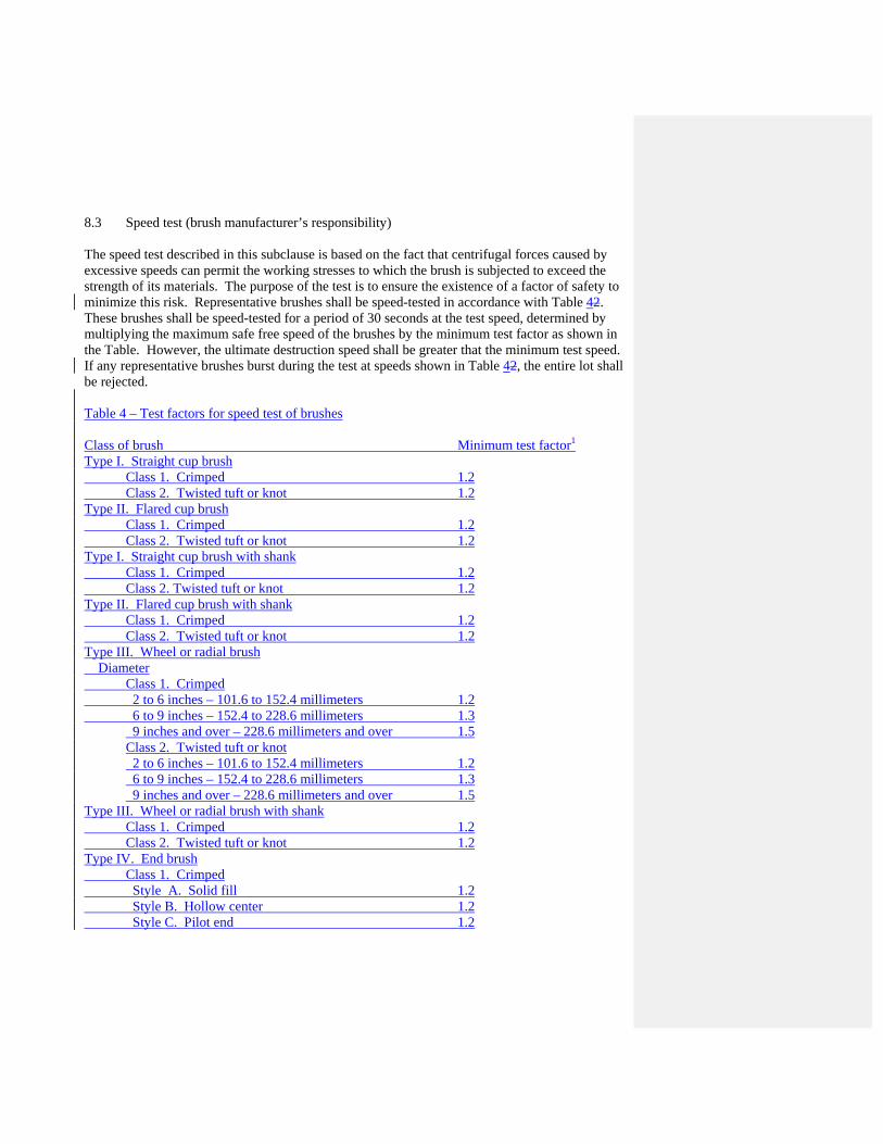
8.3 Speed test (brush manufacturer’s responsibility) The speed test described in this subclause is based on the fact that centrifugal forces caused by excessive speeds can permit the working stresses to which the brush is subjected to exceed the strength of its materials. The purpose of the test is to ensure the existence of a factor of safety to minimize this risk. Representative brushes shall be speed-tested in accordance with Table 42. These brushes shall be speed-tested for a period of 30 seconds at the test speed, determined by multiplying the maximum safe free speed of the brushes by the minimum test factor as shown in the Table. However, the ultimate destruction speed shall be greater that the minimum test speed. If any representative brushes burst during the test at speeds shown in Table 42, the entire lot shall be rejected. Table 4 – Test factors for speed test of brushes Class of brush Minimum test factor1 Type I. Straight cup brush Class 1. Crimped 1.2 Class 2. Twisted tuft or knot 1.2 Type II. Flared cup brush Class 1. Crimped 1.2 Class 2. Twisted tuft or knot 1.2 Type I. Straight cup brush with shank Class 1. Crimped 1.2 Class 2. Twisted tuft or knot 1.2 Type II. Flared cup brush with shank Class 1. Crimped 1.2 Class 2. Twisted tuft or knot 1.2 Type III. Wheel or radial brush Diameter Class 1. Crimped 2 to 6 inches – 101.6 to 152.4 millimeters 1.2 6 to 9 inches – 152.4 to 228.6 millimeters 1.3
9 inches and over – 228.6 millimeters and over 1.5 Class 2. Twisted tuft or knot 2 to 6 inches – 101.6 to 152.4 millimeters 1.2 6 to 9 inches – 152.4 to 228.6 millimeters 1.3 9 inches and over – 228.6 millimeters and over 1.5
Type III. Wheel or radial brush with shank Class 1. Crimped 1.2 Class 2. Twisted tuft or knot 1.2 Type IV. End brush Class 1. Crimped Style A. Solid fill 1.2 Style B. Hollow center 1.2 Style C. Pilot end 1.2

Class 2. Twisted tuft or knot, Hollow center 1.2 Type V. Flared end brush 1.2 Type VI. Tubular end brush With shank 1.2 Without shank 1.2 Type VII. Twisted-in wire brush No Speed Test Type VIII. Strip brush No Speed Test Type XI. Cylinder brush Class 1. Mounted by manufacturer Style A. Crimped, or twisted tuft or knot No Speed Test Style B. Straight, helix, or coil-wound strip No Speed Test Class 2. Expendable or unitized Style A. Crimped, or twisted tuft or knot No Speed Test Style B. Straight, helix, or coil-wound strip No Speed Test 1 Maximum safe free speed shall be multiplied by this test factor to establish the minimum speed at which brushes are to be tested by the brush manufacturer. This speed test is not designed to determine the mechanical properties of the brush, which should already have been determined by the brush manufacturer (see 4.1 and E4.1). In some cases, the shape, size, construction, or conditions of use of the brush make the speed test inapplicable or misleading. Examples of brushes that need not be speed-tested include twisted-in wire brushes and strip brushes. The brush manufacturer shall, upon demand, furnish certification showing that representative brushes have been speed-tested and have passed the test satisfactorily. 8.4 Brush machine and power tool builder’s responsibility All brushes classified for use under Table 2 of this standard shall be used on machines and power tools designed and equipped in accordance with all of the requirements for guards and other general machine conditions described in clauses 5 and 9. 8.5 User’s responsibility All brushes shall be used in conformance with instruction given in clauses 4 to 9. 8.5.1 Speed check of machines and power tools The speed of the spindle on brush machines or power tools shall be checked frequently with suitable instruments, by competent personnel employed by the user, to make sure that the speed is correct for the type and size of brushes used. 8.5.2 Speed adjustment control

If the speed of the machine spindle is adjustable, the speed adjustment shall be under the supervision and control of competent and authorized personnel only. Such personnel shall use care in determining that the speed at any present moment conforms to and does not exceed the peripheral speeds (in surface feet/meters per minute), the rated MSFS as established for a new brush, or both (see Table 53 and 53a). Table 5 – Conversion table for brush speeds (Surface speed in feet per minute) Brush diameter (inches) r/min* 2 3 4 6 8 10 12 15 16 200 105 157 209 314 419 524 629 785 838 400 209 314 419 628 838 1047 1257 1571 1676 600 314 471 628 942 1257 1571 1885 2356 2513 800 419 628 838 1257 1676 2094 2513 3142 3351 1000 524 785 1047 1571 2094 2618 3142 3927 4189 1200 628 942 1257 1885 2513 3142 3770 4712 5027 1400 633 1100 1466 2199 2932 3665 4398 5498 5864 1600 838 1257 1676 2513 3351 4189 5027 6283 6702 1800 942 1414 1885 2827 3770 4712 5655 7069 7540 2000 1047 1571 2094 3142 4189 5236 6283 7858 8378 2200 1152 1728 2304 3456 4608 5760 6912 8639 9215 2400 1257 1885 2513 3770 5027 6283 7540 9425 10053 2600 1361 2042 2723 4084 5445 6807 8168 10210 10891 2800 1466 2199 2932 4398 5864 7330 8796 10996 11729 3000 1571 2356 3142 4712 6283 7854 9425 11781 12566 3200 1676 2513 3351 5027 6702 8378 10053 12566 13404 3400 1780 2670 3560 5341 7121 8901 10681 13352 14242 3600 1885 2827 3770 5657 7540 9425 11310 14137 15080 3800 1990 2985 3979 5969 7959 9948 11938 14923 15917 4000 2094 3142 4189 6283 8378 10472 12566 15708 16755 4400 2304 3456 4608 6912 9215 11519 13823 17279 18431 4800 2513 3770 5027 7540 10053 12566 15080 18850 20106 5200 2723 4084 5445 8168 10891 13674 16336 20420 21782 5600 2932 4398 5864 8796 11729 14661 17593 21991 23457 6000 3142 4712 6283 9425 12566 15708 18850 23562 25133 6500 3403 5105 6807 10210 13614 17017 20420 25525 27227 7000 3665 5498 7330 10996 14661 18326 21991 27499 29322 7500 3927 5890 7854 11781 15708 19635 23562 29452 31416 8000 4189 6283 8378 12566 16755 20944 25133 31416 - 8500 4451 6676 8901 13352 17802 22253 26704 - -

9000 4712 7069 9425 14137 18850 23562 28274 - - 9500 4974 7461 9948 14923 19897 24871 29845 - - 10000 5236 7854 10472 15708 20944 26180 31416 - - 11000 5756 8639 11519 17279 23038 28798 - - - 12000 6283 9425 12566 18850 25133 31413 - - - 13000 6807 10210 13614 20420 27727 - - - - 14000 7330 10996 14661 21991 29322 - - - - 15000 7854 11781 15708 23562 31416 - - - - 16000 8377 12566 16755 25133 - - - - - 17000 8901 13352 17802 26704 - - - - - 18000 9425 14137 18850 28274 - - - - - 19000 9948 14923 19897 29845 - - - - - 20000 10472 15708 20945 31416 - - - - - 22000 11519 17279 23038 - - - - - - 24000 12566 18850 25133 - - - - - - 26000 13614 20420 27227 - - - - - - 28000 14661 21991 29322 - - - - - - 30000 15708 23562 31416 - - - - - - * Revolutions per minute for various diameters of brushes to give surface speed in feet per minute as indicated. NOTE – “Centrifugal force,” the force that tends to rupture a given brush when overspeeding, increases as the square of the velocity of that wheel brush. For example, the centrifugal force in a brush running at 5500 surface feet per minute is 49% greater than in the same brush running at 4500 surface feet per minute, although the speed is actually only 22% greater. Table 5a – Conversion table for brush speeds (Surface speed in M per minute) Brush diameter (millimeters) r/min* 51 76 102 152 203 254 305 381 406 200 32 78 64 96 128 160 192 239 255 400 64 96 128 192 255 319 383 479 511 600 96 144 192 287 383 479 585 718 766 800 128 192 255 383 511 638 766 958 1021 1000 160 239 319 479 638 798 958 1197 1277 1200 192 287 383 575 766 958 1149 1436 1532 1400 223 335 447 670 894 1117 1341 1676 1787 1600 255 383 511 766 1021 1277 1532 1915 2043 1800 287 431 575 862 1149 1436 1724 2155 2298 2000 319 479 638 958 1277 1596 1915 2394 2553

2200 351 527 702 1053 1404 1756 2107 2633 2809 2400 383 575 766 1149 1532 1915 2298 2873 3064 2600 415 622 830 1245 1660 2075 2490 3112 3320 2800 447 670 894 1341 1787 2234 2681 3351 3585 3000 479 718 958 1436 1915 2394 2873 3591 3830 3200 511 766 1021 1532 2043 2553 3064 3830 4086 3400 543 814 1085 1628 2170 2713 3256 4070 4341 3600 575 862 1149 1724 2298 2873 3447 4309 4596 3800 606 910 1213 1819 2426 3032 3639 4548 4852 4000 638 958 1277 1915 2553 3192 3830 4788 5107 4400 702 1053 1404 2107 2809 3511 4213 5267 5618 4800 766 1149 1532 2298 3064 3830 4596 5745 6128 5200 830 1245 1660 2490 3320 4149 4979 6224 6639 5600 894 1341 1787 2681 3575 4469 5362 6703 7150 6000 958 1436 1915 8273 3830 4788 5745 7182 7660 6500 1037 1556 2075 3112 4149 5187 6224 7780 8299 7000 1117 1676 2234 3351 4469 5586 6703 8379 8937 7500 1197 1795 2394 3591 4788 5985 7182 8977 9576 8000 1277 1915 2553 3830 5107 6384 7660 9576 - 8500 1357 2035 2713 4070 5426 6783 8139 - - 9000 1436 2155 2873 4309 5745 7182 8618 - - 9500 1516 2274 3032 4548 6065 7581 9097 - - 10000 1596 2394 3192 7488 6384 7980 9576 - - 11000 1756 2633 3511 5267 7022 8778 - - - 12000 1915 2873 3830 5745 7660 9576 - - - 13000 2075 3112 4149 6224 8299 - - - - 14000 2234 3351 4469 6703 8937 - - - - 15000 2394 3591 4788 7182 9576 - - - - 16000 2553 3830 5107 7660 - - - - - 17000 2713 4070 5426 8439 - - - - - 18000 2873 4309 5745 8618 - - - - - 19000 3032 4548 6065 9097 - - - - - 20000 3192 4788 6384 9576 - - - - - 22000 3511 5267 7022 - - - - - - 24000 3830 5745 7660 - - - - - - 26000 4149 6224 8299 - - - - - - 28000 4469 6703 8937 - - - - - - 30000 4788 7182 9576 - - - - - -

* Revolutions per minute for various diameters of brushes to give surface speed in meters per minute as indicated. NOTE – “Centrifugal force,” the force that tends to rupture a given brush when overspeeding, increases as the square of the velocity of that wheel brush. For example, the centrifugal force in a brush running at 5500 surface meters per minute is 49% greater than in the same brush running at 4500 surface meters per minute, although the speed is actually only 22% greater. 8.6 Requirements for special speeds On effectively guarded, fully protected machines, brushes used on special applications at speeds higher than those recommended by the brush manufacturer shall be used only in accordance with 8.6.1 through 8.6.3, as applicable. If the brush manufacturer allows a special speed, the special speed shall replace the safe free speed for that brush. In this case, the brush manufacturer shall determine the special maximum safe free speed. 8.6.1 The brush manufacturer’s responsibility It shall be the manufacturer’s responsibility to speed-test brushes required for special speeds and to identify them as being able to operate safely at special speeds. If it is impractical to mark the brush, then the box or package in which it is wrapped shall contain the required markings, either on the outside of the package or printed on an insert placed inside of the package. The brush manufacturer shall make certain that the brushes are of adequate strength, have been speed-tested in accordance with Table 42, and bear the brush manufacturer’s approval of the higher speed. 8.6.2 The brush machine builder’s responsibility The brush machine builder shall make certain at the time of manufacture that the machine has been designed and guarded in such a manner as to protect the operator from injury. It shall be the brush machine builder’s responsibility to design and construct those machine components that are concerned with the safe operation of the brushing machine at the speed and for the type of operation for which the machine is intended. Particular attention shall be given to the design of the safety guards and the mounting spindle of the brush.

If an existing machine is to be adapted for use at a special speed, the brush machine builder shall check all component parts of the brushing machine and, if necessary, modify or adjust all component parts prior to operation at the special speed. When the operation is beyond the conditions for which the guards were designed, the brush machine builder shall ensure by test or calculation that the guards are capable of withstanding the special speeds, and, if necessary, replace, modify, or adjust the guards prior to operating at the special speed. When the operating conditions are determined as exceeding the capacity of the machine and guards, the brush machine builder shall ensure by test or calculation the specifications for adequate replacement of the mechanical mechanisms and apparatus. 8.6.3 The user’s responsibility Before operating the machine at a special speed, the machine user shall make certain that the machine is operated with approved safety guards as defined in 7.7, and that the machine is maintained in a satisfactory condition, as defined in clause 5. After receipt of the brushes, it shall be the user’s responsibility to provide safe handling, storage, and inspection for the brushes designed for special needs in accordance with clause 4 and to maintain his brushing equipment in a safe operating condition at all times. Rules of safe operation of this equipment submitted by the brush machine builder shall be observed as well as those rules specified in other clauses of this standard. A user shall not operate a brush designed for special needs faster than the special maximum safe free speed established by the brush manufacturer. When an existing machine is altered by the user to operate at special speeds, the user shall assume all of the responsibility of a machine builder as outlined in this Standard. The user shall fully inform all operating personnel that only brushes identified for operation at special speeds shall be used, and that, at no time, shall the special maximum safe free speed be exceeded. 9 Handling, storage, and inspection 9.1 Handling All power-driven brushing tools can be damaged by improper handling. The following rules shall always be observed:
1) Handle brushes carefully so that the fill material is not disoriented or bent, potentially causing an imbalanced condition to exist.
2) Do not rest any brush on its face, or place any object on the face of the brush that might tend to distort the face or become imbedded in the face.
3) Do not roll cylinder brushes (barrel fashion) or wheel brushes (hoop fashion).

4) When handling cylinder brushes with a sling, do not use a sling that is narrow enough to become impressed into the face of the brush.
5) Do not open packaged brushes until they are to be used or unless they need to be inspected. After inspection, repackage them in a manner that will ensure the same amount of protection as the original package.
6) During handling, keep all brushes boxed or covered so that foreign matter cannot accumulate and become lodged in the face of the brush.
7) Place brushes carefully on shelves or in boxes, bins, or other compartments so that brushes do not rest in any way that could cause a distorted condition.
9.2 Storage Suitable racks, bins, drawers, or boxes shall be provided by the user to store the various types of brushes used. Storage recommendations of the brush manufacturer shall be followed. Brushes shall not be stored where they will be subjected to:
- Exposure to high humidity, heat, water, UV or other liquids that might induce deterioration or dimensional changes to the filaments or other brush components. (This deterioration includes rusting of ferrous metals and rotting, checking, or warping of wood and degrading of plastics.)
- Exposure to acids or fumes from acids that might induce deterioration to the filaments or other brush components.
- Any temperature low enough to cause condensation on the brushes when they are moved from storage to an area of higher temperature or humidity or both, or low enough to cause embrittlement or other deterioration to the filaments or other brush components.
- Storage that causes bent or distorted brush components. - Damaged brush filaments from sliding the brushes across abrasive or rough surface. - Exposure to the accumulation of foreign matter that may become attached to or
lodged in any of the brush components. 9.3 Inspection Immediately after being unpacked or uncrated, all brushes shall be closely inspected to make sure that they have not been damaged from handling, shipping, or other causes. If examination discloses damage, the brushes shall not be used. A typical defect that might be encountered on wire brushes is rust (oxidation), discoloration in the surface finish caused by exposure to environmental conditions.

EXPLANATORY INFORMATION (Not part of American National Standard ANSI B165.1-20130) E1 Scope It is the intent of this standard to cover all power-driven brushes, of any size, any materials, any construction or any configuration except those specifically excluded under the scope. Brushes with wood or synthetic hubs and cores, which have overall appearances very similar to power brushes of this standard, have been excluded because the parameter of construction and use differ fundamentally from brushes covered in this standard. Other brushes excluded in this standard have been omitted because of significant differences in construction, dimension, service conditions or application. E2 Bibliography (informative) ANSI/NFPA 91-2004, Blower and exhaust systems ANSI/UL 154 CAN/ULC-5503-2005, Safety standard for carbon-dioxide fire extinguishers OSHA SAFETY CODE 1910.94 OSHA Title 29, Chap. 17, Part 1910.94(b) E3.1.3 Revolutions per minute Although machine spindle speeds are usually indicated in revolutions per minute (rpm), and motor name plate speeds invariably are described in terms of the number of revolutions the motor will produce in one minute, brush speeds often classified in surface feet per minute (sfpm) or surface meters per minute (smpm). It is, therefore, essential to know the difference between how they are measured and what those measurements mean. E3.1.4 Surface feet per minute

When the diameter of a brush is indicated in inches, it is necessary to divide by 12 the result of multiplying the diameter by rpm by pi (3.1416). An example of this equation follows for a brush 12 inches in diameter turning at 1000 rpm: 3.1416 x 12 x 1000 = 3141.6 sfpm 12 This measurement is also referred to as “circumferential speed.” E3.1.4a Surface meters per minute When the diameter of a brush is indicated in millimeters, it is necessary to divide by 1000 the result of multiplying the diameter by rpm by pi (3.1416). An example of this equation follows for a brush 305 millimeters in diameter turning at 1000 rpm: 3.1416 x 305 x 1000 = 957.6 smpm 1000 This measurement is also referred to as “circumferential speed.” E3.1.9 Operating face width The width of a wheel brush rotating at operational speeds frequently is different from the width or face of the same brush in a stationary condition. The face width of brush filaments in a static brush is usually wider than the same assembly of filaments at point of attachment. When rotating at operational speeds, centrifugal force orientates all filaments into a radial, more compact configuration that substantially reduces any lateral displacement. As a result, the mass of filaments are nearly the same width at the periphery as they are at the point of attachment. E3.1.10.1 Crimped plastic fill material The configuration of crimped plastic fill materials is similar to that of crimped wire (see 3.1.13). E3.1.10.6 Bristle fill material The term “bristle,” when used in relationship to brushes, is restricted and limited to the hair of the swine exclusively and should not be used to describe any other filaments. E3.1.11 Brush flexibility The quality of a brush that determines resiliency or stiffness is measured in terms of resistance to the bending of filaments. This physical characteristic of flexibility, sometimes referred to as “modulus of elasticity (stiffness),” can be varied in a number of ways. Primary ways are as follows:
- Change modulus of elasticity of the fill materials, which varies for different materials. For example: steel, brass, hair, nylon.

- Increase or decrease the diameter of fill material. For example: 0.020 inch (.508 millimeters) steel wire is stiffer than 0.005 inch (.127 millimeters) steel wire of same analysis.
- Increase or decrease the trim length of the fill material. For example: A steel wire filament that is 0.010 inch (.254 millimeters) in diameter and 1 inch (25.4 millimeters) long is stiffer than a similar steel wire filament that is 0.010 inch (.254 millimeters) in diameter and 4 inches (101.6 millimeters) long.
- Increase or decrease the speed of rotation. For example: The faster a brush is rotated, the stiffer it becomes because of the influence of centrifugal force.
- Change the construction of the brush. For example: Filaments of wire twisted together as in a knotted or twisted tuft brush are stiffer that those in a crimped wire brush. In the knot or twisted tuft construction, the filaments being twisted together act as a family of filaments, while in a crimped wire brush, they act more independently of other filaments.
- Increase or decrease the number of brushing points per square unit of brush face. This changes the brush flexibility through wire packing, load division, or both; accordingly, flexibility increases as density decreases and, conversely, less capability to conform to the surface being brushed will result as density increases.
- Encapsulating, coating, or treating the brushes makes them less flexible than the brushes without encapsulation, coating, or treatment.
E3.1.13 Crimped wire [insert revised Illustration 1]
E3.1.17 Arbor adapter Adapter should be designed so that, when tightened, the adapter shoulder is bearing against the brush. Brushes using adapters without a shoulder are tightened to bear against the brush. When used in pairs, adapters should be of the same or proper shape to avoid cross-bending pressures and distortion of the brush; and should be of sufficient rigidity to resist distortion from mounting pressure.

Adapters can be distorted by excessive tightening, or burred by dropping; therefore, they should be checked periodically. In some brush operations in which wheel slippage may be a problem, it may be necessary to key or otherwise securely fasten the adapters to the spindle. E3.1.24 Barrier Such protection takes the form of an enclosure that isolates the operation from the remaining work area. Barriers can be either fixed or adjustable enclosures and are usually not connected with the brushing machine. E3.2.11 (1) Class 1: Cylinder or wide-face brushes that are mounted by brush manufacturer Aside from the two primary styles mentioned in this clause, there are many other types of class 1 cylinder or wide-face brushes. Since they are too numerous to describe in this standard, only the two most common styles have been included. E3.2.11 (2) Class 2: Expendable brushes, unitized brushes, or both Aside from the two primary styles mentioned in this clause, there are many other types of class 2 cylinder or wide-face brushes. Since they are too numerous to describe in this standard, only the two most common styles have been included. [insert Figure 1, 2, 3, 4, 5, 6, 7, 8, 9, 10, 11, 12, 13] E4.1 Manufacture of brushes Brush manufacturers know the basic construction of their own brushes best, are knowledgeable about the nature and characteristics of their products, and are aware of the use and functions for which they were designed. The design parameters for a brush used to defuzz a peach is obviously different from those for brushes used to descale steel. Brush manufacturers recognize the need for different strength requirements for various applications and consequently design their brushes so that the working stresses encountered in a given application will not exceed the strength of the material of the brushes. E4.2 Material The design of the brush and the material from which it is made should be established with operator safety in mind. E4.3 Marking

The required type of marking will leave permanent as well as legible admonishments and identification on the brush. The markings can be etched, molded in, or die stamped. Marking or labeling the packages of smaller items (under 1 inch or 2.54 cm) is desirable and would meet the requirements of this standard. The American Brush Manufacturers Association (ABMA) shall maintain a list of manufacturers and their marks. Each manufacturer will submit a current sample of their mark or their marks to ABMA and advise them of any future changes. All packages containing brushes should have a summary of the safety precautions given in this standard printed either on each package or on a card or slip placed inside the package. When placed inside the package, the package (or label on the package) shall be marked Warning: Read, study and understand all warnings and operating instructions on the enclosed safety slip and those provided with your power tool before using this brush. All brushes delivered to end users shall be accompanied with a copy of the summary safety precautions as available from the ABMA or packaged with the product. See Illustration 2 for the recommended text for this summary. If a copy of the summary safety precautions is unavailable, please contact ABMA [email protected] or visit the website http://www.abma.org to receive a copy. The information contained in Illustration 2 below is not part of this American National Standard (ANS) and has not been processed in accordance with ANSI’s requirements for an ANS. As such, Illustration 2 may contain material that has not been subjected to public review or a consensus process. In addition, it does not contain requirements necessary for conformance to the standard. [Insert Illustration 2] The information contained in Illustration 2 above is not part of this American National Standard (ANS) and has not been processed in accordance with ANSI’s requirements for an ANS. As such, Illustration 2 may contain material that has not been subjected to public review or a consensus process. In addition, it does not contain requirements necessary for conformance to the standard. E4.4 Balance Unlike many other rotating tools, it would be difficult for the user to bring back into true balance. E5.1 Machine design and maintenance

It is important that the maintenance of the machine be such that the equipment remains in the same condition as originally furnished. If the brush machine builder has provided special operating instructions or placed warning signs on the machine, these, as well as the general operating rules, should be followed to ensure a safe brushing operation. E5.3 Power Deterioration of operating conditions caused by insufficient power causes many problems. For example, reduction in brush speed, even while holding normal brush pressures, will cause a substantial decrease in cutting rate and efficiency. If pressure is increased to compensate for low brush speed, excessive heat and wear will be encountered, resulting in decreased cutting rate and efficiency. Reduced speed means reduced centrifugal force and a consequent reduction in the stiffness of the brush fill material. This loss of stiffness permits normal brush pressures to overflex the filament and induce premature fatigue. Over-stressed filaments that undergo fatigue will break off, creating a hazard. Adequate power will avoid this hazard. E5.4 Exhaust provision The adequacy of the ventilation should be determined by following the minimum exhaust provisions shown in E7.9 and E7.9a. If connection of an exhaust system is not possible, then personal respirators for operators and others in the area should be provided. E5.5 Diameter of spindle Spindles are also referred to as “shafts” or “arbors” depending upon the nomenclature used by the various brush machine builders. Their usual machine design generally conforms to the minimum shaft diameters shown in Table 1 and 1a. It is not uncommon for the user to unwittingly circumvent Tables 1 and 1a by requests for brushes larger in diameter than were originally intended for the machine. Since such a change in the outside diameter would also likely require a larger shaft hole and arbor, this is a dangerous practice that is to be avoided. E5.6 Work rests Measurement of the 1/8-inch (3.175 millimeter) clearance can be accomplished from the nominal face condition while the brush is stationary. Jogging of the brush will establish whether further adjustment is necessary to help compensate for a normal expansion. E5.7 Limiting brush diameter The safety guard can be used to limit the diameter of the brush on single-spindle or multiple-spindle machines. On variable-speed machines, a positive mechanical or manual regulation check should be maintained to avoid overspeeding another or full-sized brush after a worn brush has been removed.

In general, brush driving equipment that is stationary (fixed position) should use brushes with an outside diameter of 6 inches (152.4 millimeters) or larger. Portable tools (6000 rpm maximum) should use brushes 6 inches (152.4 millimeters) or smaller, whereas hand-held power tools and tools that rotate the brushes at speeds higher than 6000 rpm should use brushes 3 inches (76.2 millimeters) or smaller. In general, brush driving equipment that is stationary (fixed position) should use brushes with an outside diameter of 6 inches (152.4 millimeters) or larger. Portable tools and hand held power tools are designated size specific (i.e. 4 ½” angle grinder). The user should always match the appropriate size brush with the specified size called out on the tool. The user should also use a brush with a higher Maximum Safe Free Speed (MSFS) rating than the MAX rpm specified on the tool. E5.8 Direction of machine spindle thread In many types of equipment, such as double-end pedestal or bench grinders on which brushes are used, a right-hand thread is found on one end and a left-hand thread on the opposite end. If such machines are disassembled for maintenance or repair, it is essential that they be reassembled correctly in relation to the direction of threads. The following rule will assist in determining the proper relationship: “To remove the nut, it must be turned in the direction in which the spindle revolves when the brush is in operation.” E5.9 Length of machine spindle thread These two conditions are necessary to avoid the geometry of the threads from inadvertently preventing proper axial compressions and anchoring of brush rolls, especially when made up of sections. E5.10 Spindle, drive arbor, and arbor hole size It is important that the diameter of the spindle no be larger than the nominal size (usually +0.000 inch, -0.002 inch or +0.000 millimeter, -0.051 millimeter) and that the hole in the brush be kept suitable oversized to ensure a free fit under all operating conditions. This clearance is needed for expansion of the spindle caused by the heat of the operation. E5.11 Threaded hole brushes If the flange that is in contact with the threaded portion of the brush is not flat or is recessed, it would be possible, by tightening the brush on the arbor, to distort the brush or even pull the threaded bushing out of the brush. If the spindle stops quickly when power is shut off, the energy stored in the spinning brush may cause it to unscrew from the arbor and “spin off” the machine. To help prevent “spinning off,” the thread on the machine arbor should be maintained in good condition and the brush should be held in contact with the work piece until the brush has stopped rotating.

When applicable, a spindle end nut should be used to preclude “spinning off.” E5.12 Solid shanks for brushes to be used with collets and chucks The method of manufacture of twisted-in wire brushes precludes holding shank diameters to the same tolerances as those for shanks made by turning, forming, cold-heading, or machining techniques. E6.2 Arbor size Arbors that become undersize from wear, and brush adapters that become oversize from wear, can cause the machine to become imbalanced. The user should maintain both the arbor and the brush adapter diameters to preclude this problem. E6.3 Surface condition Excessive tightening can cause serious distortion of the flanges. They should be inspected prior to each mounting to ascertain that they are still flat and suitable for proper seating in the brush. E6.4 Bushing If the bushing is wider than the brush in which it is used, it will interfere with proper tightening of the flanges against the brush. The power required to drive a brush is transferred through the flanges. If this power is partially or completely transferred through the bushing, failure of the brush could occur. E6.5 Multiple-section brushes mounted on a common arbor In some applications of wide-face brushes that consist of sections in a stacked array mounted on a common arbor, slippage of the whole unit of brushes or of sections within the group of brushes may be a problem. In these cases, it may be necessary to key or otherwise securely fasten each of the individual brushes to the arbor. E6.6 End nut If multiple screw flanges are used, they shall be tightened uniformly to prevent springing of the flanges and to ensure even distribution of mounting pressure over the entire surface of the flanges. E6.7 Mounting of shank-type brushes Since the overhang of a shank-type brush is a factor in determining the maximum allowable operating speed, care should be taken to ensure that the overhang conforms to the limitations that have been established for the brush.

E6.8 Twisted-in wire brushes The shank of a twisted-in wire brush, because of its basic construction, is not inherently as strong as the shank on most other brushes. Therefore, it is even more important that the overhang not be excessive, and that other conditions of use avoid the load application and speed of rotation that will cause the shank to deflect, and therefore bend, instantly resulting in total destruction of the brush and creating an unsafe condition for the operator. E6.9 Strip and cylinder brushes Arbors that accommodate cylinder brushes usually are fitted with two keyways at 180° from each other. If one key is omitted, an imbalanced condition is created because of loss of weight. If only one key is used, the cylinder brush should be rebalanced before use to compensate for the asymmetrical weight distribution. E6.10 Flanges The major stresses produced in an operating brush tend to combine and become greatest at the true retaining member of the brush structure. It is therefore important that stresses due to mounting and driving do not unnecessarily concentrate on the same part of the brush. Flanges should be identical in diameter and radial bearing surface to avoid cross-bending pressures and stresses in the brush. Flanges should be large enough in diameter to approximately equal the size of the face plate of a brush, or the size that a face plate would be, if used, so that the brush retaining members (the wire anchoring means) is safely enclosed between the face plates. Such ample flanges ensure positive driving of the brush. E7.2 Inspection The first inspection should be made on the original shipping container. If there is visible evidence of damage to the container, special attention should be given to an immediate inspection of the brushes. It is important that all brushes be inspected carefully before mounting. E7.3 User’s responsibility On new and future products developed by the brush manufacturer and the brush machine builder, the standard recommended practices may apply. However, the user should review and understand provided information, operating manuals, safety data sheets, and recommended practices to ensure safe operation. E7.4 Brush speed

Based on the structural strength of the brush, a maximum safe free speed is established. This speed should not be exceeded. Faster speeds may be expected to exceed the ability of the brush to withstand the stresses that are developed by the rotational forces and tangential forces combined. E7.5 Protective clothing and equipment In normal power brushing operations, the material being removed (such as burrs, scale, dirt, weld slag, or other residue will fly off the brush with considerable force along with the brush filaments, which break off due to fatigue. The potential of serious injury exists for both the brush operator and others in the work area (possibly 50 feet (15.2 meters) or more from the brush). Before rotating the brush, the operator and others in the area are required to wear protective eye equipment and face equipment, such as safety goggles or full face shields, worn over safety glasses with side shields, along with protective clothing capable of resisting a force of 23 Newtons with a penetration of 0.5 inch (1.3 centimeters). E7.6 Additional enclosure (or barrier) Any wall, partitions, or booths serving as an enclosure or barrier for a brushing operation should be identified as such. It is the user’s responsibility to identify the additional enclosure or barrier. E7.7 Guarding of brushes Exceptions to the use of safety guards are based on the impossibility of using smaller brushes with conventional guards in place. In these cases, the work often forms a guard. Eye and face protection is particularly important when using smaller brushes. E7.7.1 Safety guards on pedestal grinders, bench and floor stands Maximum guard openings are based on the fact that the line of flight of particles from the part being brushed, swarf, and the residue from the brush will be tangential in the direction of rotation of the brush. The maximum exposure angle should not be exceeded. E7.7.2 Safety guards on automated equipment Frequently, in automated brushing equipment fitted with large cylinder brushes, the machine is made in such a manner as to totally enclose the brush. This type of guarding restrains bursting brushes, swarf produced by brushing, and brush filaments that have broken off, and also prevents access to the brush while it is rotating. E7.7.3 Interlocking safety guards

When end product safety standards for brushing machines are available, such as those mentioned in 5.1, compliance with, their guarding requirements provides sufficient protection to the users of brushes. An interlocking safety guard is not fixed, and may be operated or removed as the operation requires. However, due to an electrical or mechanical interlocking connection with the operating mechanism, the operation of the machine is prevented until the guard is returned to an operating position and the operator can no longer reach the point of danger. After mounting a brush, care should be taken to see that the electrical or mechanical mechanisms actuated by an open safety guard are operational. This should be ascertained before starting the brush. E7.8 Starting the brush This provides for the safety of the operator and others, should there have been damage to the brush, foreign matter accumulated in the brush, or malfunction of the machine from any cause. E7.9 Exhaust provision According to OSHA Safety Code 1910.94 under section 2, Table G5, the recommended minimum exhaust volume that should be used is as follows: Wheel Minimum Exhaust diameter width volume (in) (in) (ft3/min) to 9 2 300 9 to 16 3 500 16 to 19 4 610 To determine the need for an exhaust system, see OSHA Title 29, Chap. 17, Part 1910.94 (b) Table G, or ANSI/NFPA 91. E7.9a Exhaust provision According to OSHA Safety Code 1910.94 under section 2, Table G5, the recommended minimum exhaust volume that should be used is as follow: Wheel Minimum Exhaust diameter width volume (mm) (mm) (mm3/min) to 229 50.8 8.5 229 to 406 76.2 14.2 406 to 483 101.6 17.3

To determine the need for an exhaust system, see OSHA Title 29, Chap. 17, Part 1910.94 (b) Table G, or ANSI/NFPA 91. E8.2 Maximum speeds The maximum safe free speed as determined by the manufacturer is dependent upon the brush shape and strength. The strength of a brush may be defined as the ability of the brush to withstand rotational stress under no-load conditions. E8.3 Speed test (brush manufacturer’s responsibility) The test speed subjects a brush to significantly greater forces than does the maximum safe free speed. This test establishes an adequate factor of safety, provided the brushes are used in accordance with safe practices outlined in this standard, and have not been altered, damaged, or abused. The speed test does not justify operation of the brush at higher than the maximum safe free speed established by the brush manufacturer. The maximum safe free speed should never be exceeded, because the additional test strength covers other normal brushing stresses encountered in use. No simple formula can possibly accommodate all of the various types and proportions of brushes, and, at the same time, provide a uniform factor of safety for each. Because of the considerations of safety, such a formula would penalize the better constructions to accommodate the weaker designs. E8.4 Brush machine and power tool builder’s responsibility The reference to other applicable sections and regulations are important. All designers of brush machinery should be familiar with them. Their proper application has a direct relationship to the safe use of brushes. E8.5 User’s responsibility The references to other applicable sections and regulations are important. All users of brushes should be familiar with them. Their proper application has a direct relationship to the safe use of brushes. E8.5.1 Speed check of machines and power tools It is of special importance that the portable air grinders be checked to be sure that proper air pressure is maintained and that the machine governor mechanism is clean, in good operating condition, and functioning properly. This reference to air tools is not intended to downplay the necessity for a regular check of the speed on all types of brushing machines. Various types of speed-testing equipment are available, including tachometers, revolution counters, speed

indicators, and stroboscopic mechanisms. A record of such speed checks should be maintained by the user. E8.5.2 Speed adjustment control Certain machines are designed with adjustable speeds to permit maintenance of efficient surface speeds by increasing the speed of the brush spindle to compensate for the reduction of the brush diameter. E8.6 Requirements for special speeds When brushes are used at speeds in excess of standard speeds, extra precautions should be observed to ensure safe operation of the brush. E8.6.1 The brush manufacturer’s responsibility The brush manufacturer should do the testing necessary to establish an adequate factor of speed. The brush should be marked to indicate that it has been approved for high speed under specific conditions of use. E8.6.2 The brush machine builder’s responsibility The machine builder should be sure that the components of the machine, such as the spindle, bearings, guards, flanges, and horsepower, are adequate for the brushing operation. The brush machine builder and brush manufacturer should cooperate to make sure that a brush of adequate strength can be manufactured for the operation; design and composition limitations might preclude making a brush for operation at special speeds. The brush machine builder should decide upon the fitness of the machine for the proposed operation. If it becomes necessary or desirable to convert, change, or alter the machine from the design or purpose for which it was originally made by the builder, the components involved with the use of the brush should be designed in accordance with the appropriate classes of this standard. E8.6.3 The user’s responsibility The user should establish that all guards on the machine are adequate for the higher speed and should also maintain the machine in good condition for continuing safety. The special speed as determined by the manufacturer is dependent on the size, geometry, and material of the brush. In this instance, strength is defined as the ability of the brush to withstand rotational stress. E9.1 Handling

Poor handling of brushes can contribute to unsafe conditions in a number of ways. Brushes damaged as in 9.1(1), (2), (4), and (7) that have filaments permanently deformed prior to use must be expected to adversely affect brush life, fill stiffness, surface finish, and safety itself, since stress concentrations at bends will occur and higher stresses will result when non-radially disposed wires lengthen upon contact with the work surface. This condition can also create imbalance in a brush that could result in extensive damage to the machine and the operator. Brushes that are out of balance and that cannot be balanced by adding or removing weight should be removed from the machine (see 4.2). Poor handling creates safety hazards in another way, as shown in 9.1(2), (3), (5), and (6). In each instance, there is a possibility of foreign objects being lodged in the face of the brush. These imbedded objects can be thrown from the brush at great velocities when the brush attains operating speed. E9.2 Storage Any type of storage that permits the formation of rust on the filament wires or any corrosion to the filament surfaces, or that permits such mechanisms as hydrogen embrittlement to occur, can cause premature failure of the material. The failure is caused by corrosion fatigue. When corrosion occurs, there is a general roughening and etching effect that influences the fatigue strength of the material. Pitting caused by corrosion can result in a reduced cross section, thus increasing the magnitude of the stress unit. Even when only a few spots on the material are involved, the results are harmful, since the first crack will almost always occur prematurely in the corroded area, and, once started, will propagate through the unaffected area. When corrosion is occurring during in-service use due to the repeated stressing that occurs naturally in a brush during use, the deleterious effect of corrosion fatigue is even greater. Special care should be exercised to avoid this condition because filaments that have been fatigued by corrosion present a hazard since they break off in use in long lengths and fly from the brush at dangerous velocities. If rust is visible, corrosion has already become extensive enough to reduce the fatigue life of the brush. If it is unavoidable that wire brushes will be stored in an environment that may contribute to corrosion, some protective steeps can be taken. The brushes can be wrapped in protective paper before being placed in the storage area. This practice, or some equivalent, can preclude much difficulty assignable to corrosion resulting from storage conditions that are less than desirable. Some users who have less than adequate storage facilities compensate for the lack by better planning of deliveries. They schedule deliveries so that brushes do not remain long in poor storage conditions. Brushes can also be damaged by sliding them over an abrasive surface. This abrades the fill material and consequently creates a new fatigue hazard. Such fatigue failures frequently start from even superficial-appearing surface scratches, markings, and discontinuities that develop

into fatigue cracks. As the material flexes in use, these cracks, even though initially microscopic in size, propagate and material breaks off. This flying material poses a safety hazard for the brush operator and those in the area. E9.3 Inspection The first inspection should be made on the box, crate, or container in which the brushes were shipped. If there is any evidence of damage to the container, special care should be used in the inspection of brushes. Other examples of damage caused by poor handling or packaging are bent or dented shafts or arbors and disarranged working faces that preclude safe balance and concentric operation. Other typical defects may include any or all defects as a result of incorrect handling (see 9.1) and storage (see 9.2). Table 1 – Minimum spindle (shaft) diameter for brushes of various sizes (in). Maximum Diameter Maximum Face Minimum Outside Diameter of Wheel Brush Width (inches) of Spindle (Shaft) (inches) (inches) 2 3/4 1/4 3 3/4 1/4 3 (Heavy duty) 1 3/8 4 1 3/8 6 1 ¼ 1/2 8 1 ¼ 5/8 10 2 3/4 12 3 1 14 3 1 1/4 15 3 2 16 3 2 NOTE – These diameters are based upon the wheel brush being mounted next to the supported end of the bearing, rather than the unsupported end, in order to minimize overhang. Table 1a – Minimum spindle (shaft) diameter for brushes of various sizes (mm). Maximum Outside Maximum Face Maximum Outside Diameter Diameter of Width (mm) of Spindle (Shaft) Wheel Brush (mm) (mm) 50 20 6mm
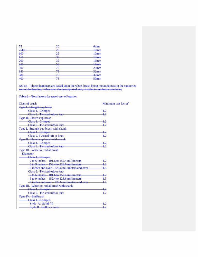
75 20 6mm 75HD 25 10mm 100 25 10mm 150 32 13mm 200 32 16mm 250 50 19mm 300 75 25mm 350 75 32mm 380 75 32mm 400 75 50mm NOTE – These diameters are based upon the wheel brush being mounted next to the supported end of the bearing, rather than the unsupported end, in order to minimize overhang. Table 2 – Test factors for speed test of brushes Class of brush Minimum test factor1 Type I. Straight cup brush Class 1. Crimped 1.2 Class 2. Twisted tuft or knot 1.2 Type II. Flared cup brush Class 1. Crimped 1.2 Class 2. Twisted tuft or knot 1.2 Type I. Straight cup brush with shank Class 1. Crimped 1.2 Class 2. Twisted tuft or knot 1.2 Type II. Flared cup brush with shank Class 1. Crimped 1.2 Class 2. Twisted tuft or knot 1.2 Type III. Wheel or radial brush Diameter Class 1. Crimped 2 to 6 inches – 101.6 to 152.4 millimeters 1.2 6 to 9 inches – 152.4 to 228.6 millimeters 1.3
9 inches and over – 228.6 millimeters and over 1.5 Class 2. Twisted tuft or knot 2 to 6 inches – 101.6 to 152.4 millimeters 1.2 6 to 9 inches – 152.4 to 228.6 millimeters 1.3 9 inches and over – 228.6 millimeters and over 1.5
Type III. Wheel or radial brush with shank Class 1. Crimped 1.2 Class 2. Twisted tuft or knot 1.2 Type IV. End brush Class 1. Crimped Style A. Solid fill 1.2 Style B. Hollow center 1.2

Style C. Pilot end 1.2 Class 2. Twisted tuft or knot, Hollow center 1.2 Type V. Flared end brush 1.2 Type VI. Tubular end brush With shank 1.2 Without shank 1.2 Type VII. Twisted-in wire brush No Speed Test Type VIII. Strip brush No Speed Test Type XI. Cylinder brush Class 1. Mounted by manufacturer Style A. Crimped, or twisted tuft or knot No Speed Test Style B. Straight, helix, or coil-wound strip No Speed Test Class 2. Expendable or unitized Style A. Crimped, or twisted tuft or knot No Speed Test Style B. Straight, helix, or coil-wound strip No Speed Test 1 Maximum safe free speed shall be multiplied by this test factor to establish the minimum speed at which brushes are to be tested by the brush manufacturer. Table 3 – Conversion table for brush speeds (Surface speed in feet per minute) Brush diameter (inches) r/min* 2 3 4 6 8 10 12 15 16 200 105 157 209 314 419 524 629 785 838 400 209 314 419 628 838 1047 1257 1571 1676 600 314 471 628 942 1257 1571 1885 2356 2513 800 419 628 838 1257 1676 2094 2513 3142 3351 1000 524 785 1047 1571 2094 2618 3142 3927 4189 1200 628 942 1257 1885 2513 3142 3770 4712 5027 1400 633 1100 1466 2199 2932 3665 4398 5498 5864 1600 838 1257 1676 2513 3351 4189 5027 6283 6702 1800 942 1414 1885 2827 3770 4712 5655 7069 7540 2000 1047 1571 2094 3142 4189 5236 6283 7858 8378 2200 1152 1728 2304 3456 4608 5760 6912 8639 9215 2400 1257 1885 2513 3770 5027 6283 7540 9425 10053 2600 1361 2042 2723 4084 5445 6807 8168 10210 10891 2800 1466 2199 2932 4398 5864 7330 8796 10996 11729 3000 1571 2356 3142 4712 6283 7854 9425 11781 12566 3200 1676 2513 3351 5027 6702 8378 10053 12566 13404 3400 1780 2670 3560 5341 7121 8901 10681 13352 14242 3600 1885 2827 3770 5657 7540 9425 11310 14137 15080 3800 1990 2985 3979 5969 7959 9948 11938 14923 15917

4000 2094 3142 4189 6283 8378 10472 12566 15708 16755 4400 2304 3456 4608 6912 9215 11519 13823 17279 18431 4800 2513 3770 5027 7540 10053 12566 15080 18850 20106 5200 2723 4084 5445 8168 10891 13674 16336 20420 21782 5600 2932 4398 5864 8796 11729 14661 17593 21991 23457 6000 3142 4712 6283 9425 12566 15708 18850 23562 25133 6500 3403 5105 6807 10210 13614 17017 20420 25525 27227 7000 3665 5498 7330 10996 14661 18326 21991 27499 29322 7500 3927 5890 7854 11781 15708 19635 23562 29452 31416 8000 4189 6283 8378 12566 16755 20944 25133 31416 - 8500 4451 6676 8901 13352 17802 22253 26704 - - 9000 4712 7069 9425 14137 18850 23562 28274 - - 9500 4974 7461 9948 14923 19897 24871 29845 - - 10000 5236 7854 10472 15708 20944 26180 31416 - - 11000 5756 8639 11519 17279 23038 28798 - - - 12000 6283 9425 12566 18850 25133 31413 - - - 13000 6807 10210 13614 20420 27727 - - - - 14000 7330 10996 14661 21991 29322 - - - - 15000 7854 11781 15708 23562 31416 - - - - 16000 8377 12566 16755 25133 - - - - - 17000 8901 13352 17802 26704 - - - - - 18000 9425 14137 18850 28274 - - - - - 19000 9948 14923 19897 29845 - - - - - 20000 10472 15708 20945 31416 - - - - - 22000 11519 17279 23038 - - - - - - 24000 12566 18850 25133 - - - - - - 26000 13614 20420 27227 - - - - - - 28000 14661 21991 29322 - - - - - - 30000 15708 23562 31416 - - - - - - * Revolutions per minute for various diameters of brushes to give surface speed in feet per minute as indicated. NOTE – “Centrifugal force,” the force that tends to rupture a given brush when overspeeding, increases as the square of the velocity of that wheel brush. For example, the centrifugal force in a brush running at 5500 surface feet per minute is 49% greater than in the same brush running at 4500 surface feet per minute, although the speed is actually only 22% greater. Table 3a – Conversion table for brush speeds (Surface speed in M per minute)

Brush diameter (millimeters) r/min* 51 76 102 152 203 254 305 381 406 200 32 78 64 96 128 160 192 239 255 400 64 96 128 192 255 319 383 479 511 600 96 144 192 287 383 479 585 718 766 800 128 192 255 383 511 638 766 958 1021 1000 160 239 319 479 638 798 958 1197 1277 1200 192 287 383 575 766 958 1149 1436 1532 1400 223 335 447 670 894 1117 1341 1676 1787 1600 255 383 511 766 1021 1277 1532 1915 2043 1800 287 431 575 862 1149 1436 1724 2155 2298 2000 319 479 638 958 1277 1596 1915 2394 2553 2200 351 527 702 1053 1404 1756 2107 2633 2809 2400 383 575 766 1149 1532 1915 2298 2873 3064 2600 415 622 830 1245 1660 2075 2490 3112 3320 2800 447 670 894 1341 1787 2234 2681 3351 3585 3000 479 718 958 1436 1915 2394 2873 3591 3830 3200 511 766 1021 1532 2043 2553 3064 3830 4086 3400 543 814 1085 1628 2170 2713 3256 4070 4341 3600 575 862 1149 1724 2298 2873 3447 4309 4596 3800 606 910 1213 1819 2426 3032 3639 4548 4852 4000 638 958 1277 1915 2553 3192 3830 4788 5107 4400 702 1053 1404 2107 2809 3511 4213 5267 5618 4800 766 1149 1532 2298 3064 3830 4596 5745 6128 5200 830 1245 1660 2490 3320 4149 4979 6224 6639 5600 894 1341 1787 2681 3575 4469 5362 6703 7150 6000 958 1436 1915 8273 3830 4788 5745 7182 7660 6500 1037 1556 2075 3112 4149 5187 6224 7780 8299 7000 1117 1676 2234 3351 4469 5586 6703 8379 8937 7500 1197 1795 2394 3591 4788 5985 7182 8977 9576 8000 1277 1915 2553 3830 5107 6384 7660 9576 - 8500 1357 2035 2713 4070 5426 6783 8139 - - 9000 1436 2155 2873 4309 5745 7182 8618 - - 9500 1516 2274 3032 4548 6065 7581 9097 - - 10000 1596 2394 3192 7488 6384 7980 9576 - - 11000 1756 2633 3511 5267 7022 8778 - - - 12000 1915 2873 3830 5745 7660 9576 - - - 13000 2075 3112 4149 6224 8299 - - - -

14000 2234 3351 4469 6703 8937 - - - - 15000 2394 3591 4788 7182 9576 - - - - 16000 2553 3830 5107 7660 - - - - - 17000 2713 4070 5426 8439 - - - - - 18000 2873 4309 5745 8618 - - - - - 19000 3032 4548 6065 9097 - - - - - 20000 3192 4788 6384 9576 - - - - - 22000 3511 5267 7022 - - - - - - 24000 3830 5745 7660 - - - - - - 26000 4149 6224 8299 - - - - - - 28000 4469 6703 8937 - - - - - - 30000 4788 7182 9576 - - - - - - * Revolutions per minute for various diameters of brushes to give surface speed in meters per minute as indicated. NOTE – “Centrifugal force,” the force that tends to rupture a given brush when overspeeding, increases as the square of the velocity of that wheel brush. For example, the centrifugal force in a brush running at 5500 surface meters per minute is 49% greater than in the same brush running at 4500 surface meters per minute, although the speed is actually only 22% greater.

NOTES 1 The illustration shows a single-plane crimped filament; however, dual-plane crimped
filaments are more commonly used. 2 F=Full wave length; F/2 = Half wave length; D = Filament diameter; A=Crimp amplitude Illustration 1 – Single-plane crimped filament Illustration 2 – Summary – Power brush Safety Requirements WARNING: Failure to observe safety precautions may result in injury. Summary - Power Brush Safety Requirements Eye Protection: Safety goggles or full face shields worn over safety glasses with side shields must be worn by all operators and others in the area of power brush operations. Comply with the requirements of ANSI/ISEA Z87.1, “Occupational and Education Eye and Face Protection.” Guards: Keep all machine guards in place. Speeds: Observe all speed restrictions indicated on the brushes, containers, labels, or printed in pertinent literature. “MSFS” means Maximum Safe Free Speed (rpm) – spinning free with no work applied. For reasons of safety, the “MSFS” should not be exceeded under any circumstances.

Safety standards: Comply with the Safety Standards of the Industrial Division of the American Brush Manufacturers Association and American National Standards ANSI B165.1, “Safety Requirements – Power Brushes”. Protective equipment: Use appropriate protective clothing and equipment (such as gloves, respirators, etc.) where possibility of injury exists that can be prevented by such clothing or equipment. Figure 1 – Type I, Straight cup brush a) Class 1, Crimped wire, abrasive-loaded plastic, plastic, fiber, or hair fill material b) Class 2, Twisted tuft or knot fill material Figure 2 – Type II, Flared cup brush a) Class 1, Crimped wire, abrasive-loaded plastic, plastic, fiber, or hair fill material b) Class 2, Twisted tuft or knot fill material Figure 3 – Type I, Straight cup brush with shank a) Class 1, Crimped wire, abrasive-loaded plastic, plastic, fiber, or hair fill material b) Class 2, Twisted tuft or knot fill material Figure 4 – Type II, Flared cup brush with shank a) Class 1, Crimped wire, abrasive-loaded plastic, plastic, fiber, or hair fill material b) Class 2, Twisted tuft or knot fill material Figure 5 – Type III, Wheel or radial brush a) Class 1, Crimped wire, abrasive-loaded plastic, plastic, fiber, or hair fill material b) Class 2, Twisted tuft or knot fill material Figure 6 – Type III, Wheel or radial brush with shank Style A, Solid filled end brush Style B, Hollow center end brush Style C, Pilot end brush a) Class 1, Crimped wire, abrasive-loaded plastic, plastic, fiber, hollow center, or hair fill
material

b) Class 2, Twisted tuft or knot fill material, hollow center Figure 7 – Type IV, End brush a) Bottom view b) Side view Figure 8 – Type V, Flared end brush a) Without shank b) With shank Figure 9 – Type VI, Tubular end brush a) Double stem construction b) Single stem construction c) Double stem, single spiral d) Single stem, single spiral e) Double stem, double spiral Figure 10 – Type VII, Twisted-in wire brush (or tube cleaning brush) Figure 11 – Type VIII, Strip brush Crimped wire, abrasive-loaded plastic, plastic, fiber or hair fill material Twisted tuft or knot fill material a) Style A, Sectional built-up face Straight strip Helix strip Coil-wound strip b) Style B, Strip face Figure 12 – Type IX, Class 1, Cylinder or wide-face brushes mounted by manufacturer Crimped wire, abrasive-loaded plastic, plastic, fiber or hair fill material Twisted tuft or knot fill material a) Style A, Sectional built-up face Straight strip Helix strip Coil-wound strip b) Style B, Strip face

Figure 13 – Type IX, Class 2, Expendable or unitized cylinder or wide-face brushes