b32101 - air brake systems testing - fronz · tranz rail ltd m9103 - standard test code, locomotive...
TRANSCRIPT

Effective Date: 27 June 2006 All printed copies are uncontrolled
FRONZ / ONTRACK
APPROVED CODE OF PRACTICEFOR
HERITAGE NETWORK OPERATORS
Mechanical Code of PracticeB3.2.1.01
AIR BRAKE SYSTEMSTESTING
IssuePrepared (P),Reviewed (R),Amended (A)
Approved by Effective Date
1 P McCallum (P) Heritage Technical Committee 27 June 20061.1 P McCallum (A) 7 May 2007
Reference Material
Source Description DateTranz Rail Ltd Loco-hauled Passenger Car and Van Brake Manual 5 June 1996Tranz Rail Ltd M9103 - Standard Test Code, Locomotive Brake All
Classes (Except Ef)Sep 1996
New ZealandRailways
Standard Test Code For A.6-E.T. And A.7-E.L. AirBrake Equipments
24 April 1959
New ZealandRailways
Testing Standard Automatic And Non-Automatic AirBrake Equipment On Locomotives And Rail TypeShunting Tractors
21/14/1959
SteamIncorporated
COP 6 - Air Brake Code For Steam Locomotives 2 September2002
Mainline Steam MSHT002 - Test Results for A6ET BrakeNew ZealandRailways
Steam Driven Air Compressors (Extract only) 28 April 1958
New ZealandRailways
Drawing Y21170 – Air End Test. Orifice Nut. AirCompressors.
18 March1966
New ZealandRailways
Standard Test Code for Railcars prepared by JimNichols, Vehicle Inspector
The holder of printed or duplicated copies of this document isresponsible for ensuring they are using the latest version.

Effective Date: 27 June 2006 All printed copies are uncontrolled
Amendment History
Version Section AmendmentDraft Released 22/12/20051.0 Index Amended
7 Added 6Sl brake test codeA1 Added 6Sl brake test record
1.1 5 Corrected Steam End Test table.

FRONZ / ONTRACK Code B3.2.1.01Issue 1.1
Air Brake Systems - TestingPage i
Effective Date: 27 June 2006 All printed copies are uncontrolled
Index
Section Page
Introduction i
Notes i
Section 1 - Efficiency (Functional) Tests 1.1
Section 2 - Passenger Cars and Service Vehicles on PassengerTrains
2.1
Source Material 2.1
Contents 2.1
Section 3 - 26L and No 4 Locomotive Brakes 3.1
Source Material 3.1
Contents 3.1
Section 4 - A.6-E.T. And A.7-E.L. Locomotive Brake Equipment 4.1
Source Material 4.1
Contents 4.1
Section 5 – Testing Steam Driven Air Compressors 5.1
Source Material 5.1
Contents 5.1
Section 6 – Railcar Brake Equipment 6.1
Source Material 6.1
Contents 6.1
Section 7 – 6SL Brake equipment 7.1
Source Material 7.1
Contents 7.1
Appendix A - Sample Record Sheets A.1
Contents A.1
IntroductionThe purpose of these tests is to ensure that vehicle brake system are working correctly andcomply with the standards for operation on the National Rail System.
Notes1 Deletions from the original codes are showing by strikethrough eg 95 lbs2 Additions to the original codes are shown in brackets eg [550 kPa]
FRONZ / ONTRACK Code B3.2.1.01Issue 1
Air Brake Systems - TestingPage 1.1
Effective Date: 27 June 2006 All printed copies are uncontrolled
Section 1Brake System Testing
Efficiency (Functional) Tests
SourceToll Rail Operating CodeSteam Inc COP 6 - Air Brake Code For Steam Locomotives; 2 September 2002
Contents
Section Page
1.1 Introduction 1.1
1.1 Locomotives 1.1
1.2 Cars and Wagons 1.2
1.1 IntroductionBrake efficiency (or functional) tests are to be done as called for in the various codes andregulations.
In general they are performed when rail vehicles are being prepared for operation.
1.2 LocomotivesCheck that brakes apply by observing that the piston travels are within the range specified forthe brake cylinder type and that the blocks press firmly on the wheels. Check that they releasecorrectly. Both the automatic and independent brakes are to be tested in turn.
With the automatic brake, a reduction of approximately 100 kPa (15 psi) is to be made, and withthe independent brake a full application is to be made.
Perform a brake pipe leakage test by:-Close the headstock coupling cocks.Using the automatic brake valve make a 75 kPa (10 psi) reduction.Cut out the automatic brake.The brake pipe pressure must not drop more than 20 kPa (3 psi) in one minute.Cut in the automatic brake and release it.
.Perform a main reservoir leakage test by:
Make sure the handbrake is applied.Place the independent valve in the release position.Cut out the automatic brake.Allow the compressor to charge the main reservoir to its upper limit and then stop it.The main reservoir pressure must not drop more than 20 kPa (3 psi) in one minute.Cut in the automatic brake and re-apply the independent brake. Restart the compressor.
Remedy any readily detectable air leaks.
Test the operation of the hand-brake by applying it firmly and check that the blocks press firmlyagainst the wheels. Check that the hand-brake releases correctly.
Test the operation of the vigilance device (if fitted).
Check that the event recorder is functioning correctly.

FRONZ / ONTRACK Code B3.2.1.01Issue 1
Air Brake Systems - TestingPage 1.2
Effective Date: 27 June 2006 All printed copies are uncontrolled
1.3 Cars and Wagons
This test may be applied to an individual vehicle or to a group of coupled vehicles.
With a locomotive attached (or a single car tester if only one vehicle), make a reduction intrain pipe pressure of 100 kPa. Make a visual inspection of each vehicle and ascertain thatthe brakes are applied, brake piston travel is within limits, and there are no audible air leaks.
While at the furthest vehicle from the locomotive, have the brake pipe recharged to normalworking pressure. Check that the brakes start releasing promptly at the rear vehicle. Make avisual inspection of each vehicle and ascertain that the brakes have released, and there areno audible air leaks.
For a complete train perform a brake pipe leakage test (this is usually done by the loco engineeras part of the train examination brake test.).From the locomotive make a brake pipe pressure reduction of 100 kPa.After the vehicle brakes are stabilised, cut out the loco brakes and observe the brake pipe
pressure gauge. Leakage should not exceed 35 kPa per minute and the train cannot departif the leakage is excess of 50 kPa per minute.
Cut in the loco brakes and release the brakes.

FRONZ / ONTRACK Code B3.2.1.01Issue 1
Air Brake Systems - TestingPage 2.1
Effective Date: 27 June 2006 All printed copies are uncontrolled
Section 2Brake System Testing
Cars and Service Vehicles on Passenger Trains
Source Material – Tranz Rail Loco-hauled Passenger Car and Van Brake Manual, 5 June1996
Contents
Section Page
2.1 Assumptions 2.2
2.2 Equipment Requirements 2.2
Test Procedures 2.2
2.3 Visual 2.2
2.4 Charge vehicle 2.2
2.5 Brake Pipe Leakage 2.2
2.6 Piston Travel 2.2
2.7 Rigging & Handbrake Test 2.3
2.8 Automatic Slack Adjuster (when fitted) 2.3
2.9 Minimum Reduction Test 2.3
2.10 Slow Release Test 2.4
2.11 Passenger Emergency Valve Test 2.4
2.12 Release Valve Test 2.4
2.13 Final Leakage Test 2.4
2.14 Brake Pipe Maintenance and Auxiliary Leakage 2.5
2.15 Recording 2.5

FRONZ / ONTRACK Code B3.2.1.01Issue 1
Air Brake Systems - TestingPage 2.2
Effective Date: 27 June 2006 All printed copies are uncontrolled
2.1 AssumptionsThese tests do not cover freight only equipment such as Empty/Load systems,accelerated release or retarded recharge features.
2.2 Equipment RequirementsSingle car brake tester or equivalent capable of
o Measuring the air pressure in the vehicle brake system. (The gaugeshould be graduated to 20 kPa divisions or better).
o Supplying air to the vehicle brake pipe at 550 kPa. [Charge]o Isolating the vehicle brake system for leakage tests.o Exhausting air from the vehicle to atmosphere through a 1.5 mm diameter
choke. [Apply]o Supplying air to the vehicle through a No 74 drill (nearest metric equivalent
= 0.58 mm) diameter choke. [Sensitive Release]o Supplying air to the vehicle brake pipe at 475 kPa. [Brake Pipe
Maintenance]o Have prescribed daily and annual test procedures.
StopwatchDummy hose coupling(s).
Test Procedures
2.3 VisualA complete visual and audible inspection should be first made for worn brake
blocks, missing or damaged rigging, etc. All faults should be repaired beforecontinuing with testing.
The triple valve should be checked to ensure the valve size, and its exhaustchoke, match the cylinder. (Triple valves get changed between inspections andmistakes get made.)
2.4 Charge vehicleTest single car tester to daily test code.Couple tester to vehicle via a brake hose.Open all brake cocks and fit dummy coupling(s) to the unused hose(s). (This
allows the brake cocks and hoses to be included in the tests.) Check that cocksmove freely.
Charge brake pipe to 550 kPa. (Allow 10 minutes to charge an unchargedvehicle).
Check for air leaks in the piping etc.
2.5 Brake Pipe LeakageCharge brake system to 550 kPa and close off air supply.Measure the drop in brake pipe pressure over 1 minute. The total drop should
ideally be zero but must be less than 15 kPa over 1 minute. If the leakage is too high close the feed valve to the water lifting gear, air doors,
etc (if fitted). If the leakage decreases the leak is in the auxiliary apparatus.The leakage must be reduced to less than 15 kPa before continuing with the
remaining tests.
2.6 Piston TravelReduce the train pipe pressure to 400 kPa (150 kPa reduction) by exhausting air
via a 1.5 mm diameter choke and observe if the brakes apply.The piston travel should be between limits for the cylinder type.

FRONZ / ONTRACK Code B3.2.1.01Issue 1
Air Brake Systems - TestingPage 2.3
Effective Date: 27 June 2006 All printed copies are uncontrolled
Long-stroke cylinders (about 300 mm long):No slack adjuster (new blocks): 125–200 mmManual slack adjuster (new blocks): 125–200 mmSAB slack adjuster and single stage braking: 125–130 mmSAB slack adjuster and two-stage braking: 140 mm in load conditionPneumatic slack adjuster: 150 - 165 mmShort-stroke cylinders (about 200 mm long):Manual slack adjuster (new blocks): 65–125 mmSAB slack adjuster and two-stage braking: 100 mm in load conditionAUSCOPAC systems: 28–32 mm with new
blocks
Possible faults are:-
Fault Possible ReasonsBrakes do not apply Faulty triple valve
Faulty automatic release valve diaphragmPiston travel too short Hockey stick adjusting nuts at faultPiston travel too long Hockey stick adjusting nuts loose
Automatic slack adjuster not workingAutomatic slack adjuster at end of travelFaulty brake rigging (eg pin missing)
Brakes do not release Faulty triple valveFaulty release valveSeized brake rigging
Check at brake cylinder for audible air leakage.
2.7 Rigging & Handbrake TestWith the brakes applied (150 kPa reduction) check all rigging and levers to ensure
they are at the correct angles and will not foul on any obstructions as the blockswear. (Pay particular attention to bogie brake levers as their movement can berestricted; the yokes around the bogie centre to ensure they won’t hit the centrecasting as the blocks wear; and the shoe hangers. On 25140 bogies with smalltyres these hangers can foul the frame as the blocks wear.)
Check the handbrake operation.On carriages with automatic slack adjusters handbrakes should apply after 6
- 8 turns.On carriages and vans with manual slack adjusters handbrakes should apply
after 5 - 10 turns, depending on type and brake block wear.Van (FM type) handbrakes should apply after 1 - 6 turns.Wagon handbrakes (lever type) should not bottom with weight applied to the
lever.
2.8 Automatic Slack Adjuster (when fitted)When the piston travel is correct (see Piston Travel Test) release the brakes and
screw the slack adjuster out (both SAB and pneumatic types), so that the travelwill increase.
Make a 150 kPa reduction. On pneumatic adjusters check the piping for leaks.Release the brakes and check that the adjuster works. (If you can’t watch the
adjuster move use a chalk witness mark.)

FRONZ / ONTRACK Code B3.2.1.01Issue 1
Air Brake Systems - TestingPage 2.4
Effective Date: 27 June 2006 All printed copies are uncontrolled
2.9 Minimum Reduction TestTest that the brakes will operate on the minimum reduction in brake pipe pressurethat occurs during brake application.. The minimum reduction applied by a locomotivebrake system (or the driver) should be 50 kPa so the test is done at 40 kPa reductionto allow a safety margin.Charge vehicle brake system fully to 550 kPa.Make a reduction of 40 kPa. The brakes should apply and remain applied for 1
minute.Possible faults are:-
Fault Possible ReasonsBrakes do not apply Faulty triple valve
Faulty release valveBrakes release in lessthan 1 minute
Air leak from auxiliary reservoir (this should havebeen detected during the Brake Pipe LeakageTest)
Check for air blow at the triple valve exhaust. Only a slight blow is allowed.
2.10 Slow Release TestTest that the brakes will correctly release when the train pipe pressure rises slowly(this simulates the case of a vehicle at the rear of a long train).Reduce brake pipe pressure to 465-480 kPa.When the pressure gauge is steady open the Slow Release Valve to supply air at
550 kPa to the brake pipe via a No 74 drill choke (0.58 mm diameter) and notethe time until the air starts exhausting from the triple valve. The time must beless:-
Bogie vehicles with 1¼ “ dia brake pipe 25 seconds*
Bogie vehicles with 1“ dia brake pipe 15 seconds
4 wheel vehicles 15 seconds
[* Modern code is 25 seconds. The figures for other vehicles are derived fromolder codes and advice from railway staff.]
Possible faults are:-
Fault Possible ReasonsBrakes do not start releasing inprescribed time
Excessive brake pipe leakageFaulty triple valveLeaking automatic release valve
diaphragm
When brakes are fully released, check for air blow at the triple valve exhaust.Only a slight blow is allowed.
2.11 Passenger Emergency Valve TestFully charge system to 550 kPaOperate each Emergency Valve in turn and check that the brakes apply and the
valves move freely. Restore each valve after testing.
2.12 Release Valve TestManual TypeApply the brakesOperate the cock and check that air exhausts from the reservoir and the brakes
release.

FRONZ / ONTRACK Code B3.2.1.01Issue 1
Air Brake Systems - TestingPage 2.5
Effective Date: 27 June 2006 All printed copies are uncontrolled
Release the cock and check that it closes.
Automatic typeApply the brakes (150 kPa reduction).Operate the cock and check that air exhausts from the reservoir and the brakes
release.Release the cock and check that it closes.Exhaust the brake pipe (reduce the pressure to zero)Operate the cock and release it. It should remain open until the reservoir empties.
2.13 Final Leakage TestA repeat of the leakage test on page 2 is advisable, as it will reveal if the emergencyvalve cocks, relay valve or release valve have increased leakage after operation.(The only time these normally get used is during these brake tests.)
2.14 Brake Pipe Maintenance and Auxiliary Leakage (10 Minute Application Test)Charge vehicle brake system fully to 550 kPaReduce brake pipe pressure to 475 kPa and maintain this for 10 minutes. The
brakes must apply and remain applied for the10 minutes.Possible faults are:-
Fault Possible ReasonsBrakes release with no sound of escapingair from triple valve
Severe brake cylinder leakageLeakage from gasket between
reservoir and brake cylinder(combined sets)
Brakes release due to triple valve releasing(sound of air escaping from triple valve)
Air leak from auxiliary reservoirfrom:-triple valve mounting gasketrelease valve and its piping
2.15 RecordingThe results of each test should be recorded on an appropriate record sheet.
For sample test records see Appendix A

FRONZ / ONTRACK Code B3.2.1.01Issue 1
Air Brake Systems - TestingPage 3.1
Effective Date: 27 June 2006 All printed copies are uncontrolled
Section 3Brake System Testing
26L and No 4 Locomotive Brakes
Source MaterialTranz Rail Ltd M9103 - Standard Test Code, Locomotive Brake All Classes (Except Ef) - Sep
1996(First Issued as Code Ml 1-7 September 1990. Reissued June 1995)
New Zealand Railways Mechanical Branch - Testing Standard Automatic And Non-AutomaticAir Brake Equipment On Locomotives And Rail Type Shunting Tractors; 21/14/1959
Contents
Section Page
3.1 General 3.2
3.2 Test 1 Charging 3.2
3.3 Test 2 Pressure gauges 3.2
3.4 Test 3 Compressor governor or Unloader setting 3.2
3.5 Test 4 Main Reservoir Leakage 3.3
3.6 Test 5 Reservoir Check Valve 3.3
3.7 Test 6 Brake Pipe Leakage 3.3
3.8 Test 7 Air Compressor Check 3.3
3.9 Test 8 Auto brake valve 3.4
3.10 Test 9 Brake Pipe Maintaining Feature 3.6
3.11 Test 10 Independent Brake 3.6
3.12 Test 11 Cut off Valve 3.6
3.13 Test 12 Lead or Trail Selector 3.6
3.14 Test 13 Dynamic Interlock 3.7
3.15 Test 14 Brake Cylinder Leakage 3.7
3.16 Test 15 Brake-in-two 3.8
3.17 Test 16 Main Reservoir Safety Valve 3.8
3.18 Test 17 Vigilance Control 3.8
3.19 Test 18 General 3.9
3.20 Test 19 Main Reservoir Protection (Eo, Dj only) 3.9

FRONZ / ONTRACK Code B3.2.1.01Issue 1
Air Brake Systems - TestingPage 3.2
Effective Date: 27 June 2006 All printed copies are uncontrolled
3.1 General
A locomotive is to be given this code test prior to ‘Passing Out” after major servicingand when called for in the servicing schedule or when doubt exists as to the correctingfunctioning of the brake equipment
When a locomotive has two sets of controls then the test must be repeated for eachset.
The brake valves must be returned to the release position at the completion of eachtest.
Not all locomotives are fitted with all the equipment covered by this test code.
Test gauges must be tested annually for accuracy by a certified testing agency.
All test equipment must be kept in suitable containers to prevent damage betweenuse.
A manifold, which couples the master gauge to the various pressure sources, may beused for the code test.
3.2 Test 1: Charging
Ensure that main reservoirs are drained, that oil level is correct in the compressor, thatbrake valve cut off valve is at ‘in’ or ‘open’ position and MU valve, is fitted, is at “Leadposition”. All brake valves in the cab being tested should be in release position.
Start the compressor and note the pressure rises steadily with no undue noise orvibration.
With steam driven compressors see that the cylinder drain cocks are open and run thecompressor slowly until about 30 lb main reservoir pressure is obtained, then close thedrain cocks and increase the speed. Check compressor(s) for pounding and unevenstroking.
3.3 Test 2 : Pressure Gauge
(1) Main Reservoir: Place standard test gauge on MR hose at headstock or drainfrom reservoir or at test location point if provided. Full pressure on locomotivegauges must be correct to within ± 20 kPa of indicated pressure on test gauge.
(2) Brake pipe and equalising reservoir: Place standard test gauge onto BP hoseat headstock. Pressure on locomotive gauges must be correct to within ± 15kPa of test gauge at 550 kPa. Leave test gauge on until all tests arecompleted.
(3) Brake cylinder: Place test gauge on brake cylinder equalising hose or controlpipe at headstock or onto brake cylinder delivery line. Make a full serviceapplication with independent brake valve and compare locomotive gauge withtest gauge at 350 kPa. Pressure must be within ±10 kPa.
3.4 Test 3 : Compressor Governor Or Unloader Setting
Except where stated all locomotive Governors must load the compressor when themain reservoir pressure has dropped to 875 kPa and unload when the pressure has

FRONZ / ONTRACK Code B3.2.1.01Issue 1
Air Brake Systems - TestingPage 3.3
Effective Date: 27 June 2006 All printed copies are uncontrolled
risen at least 75 kPa but not more than 100 kPa. Locomotives fitted with a governorhaving the differential readily adjusted should be set at 100 kPa differential.
Dsc class locomotive governors will be set to load at 650 kPa and to cut out at notgreater than 750 kPa.
EO, DJ class locomotives set governor to load at 725 kPa, cut out at 800-825 kPa. DE,DSA, DSC class locomotives governors will be set to load at 650 kPa and to cut out atnot greater than 750 kPa.
TR class locomotives compressors cut in at 575 kPa and cut out at 700 kPa.
For steam locomotives the governor should cut out at 700 kPa (100 psi) and cut inwhen the pressure has dropped by between 15 and 35 kPa (2.5 and 5 psi).
3.5 Test 4 : Main Reservoir Leakage
(1) Stop compressor and adjust main reservoir pressure to 550 kPa, place brakevalve cut off valve into cutout position. Main reservoir pressure must not dropmore than 20 kPa in one minute and any leakage must be reduced to thisamount before continuing with test. On remote control locomotives set the cutover cocks to manual.
(2) On locomotives fitted with check valve between No.1 and No.2 reservoirs theleakage must be observed on both sides of valve. Couple the standard testgauge to No. 1 main reservoir unless the locomotive is fitted with a gauge onthe line from the compressor to No.1 reservoir.
3.6 Test 5 : Reservoir Check Valve
Blow down the pressure in No.1 reservoir as shown by the test gauge to about 200kPa below the pressure in No.2 reservoir as shown in cab gauge. Time over 1 minute,pressure in No.2 reservoir should not drop greater than 50 kPa in 1 min. No.1 reservoirshould not rise greater than 50 kPa. This would indicate a defective check valvebetween reservoirs.
3.7 Test 6 : Brake Pipe Leakage
Make a 75 kPa brake pipe reduction. Place cut off valve in cut out position. Brake pipepressure must not drop more than 15 kPa in one minute. Leakage must be reduced tothat amount before continuing the tests. Note the brake pipe pressure must not riseduring the one minute.
3.8 Test 7 : Air Compressor Check
These may be tested either by orifice test or by the time taken to charge the mainreservoir from 0 kPa to 550 kPa.
For steam driven compressors see Appendix A for test procedures.
After a compressor change the replacement must be tested. TR class must be orificetested on all occasions.
Electric locomotives must be tested at normal line voltage.

FRONZ / ONTRACK Code B3.2.1.01Issue 1
Air Brake Systems - TestingPage 3.4
Effective Date: 27 June 2006 All printed copies are uncontrolled
Where required check oil pressure is not less than 100 kPa and that there is no oil, airor water leak at the compressor or its piping.
3.8.1 Charging Test
On locomotives fitted with more than one compressor each compressor is timedseparately. All pressures are recorded from the test gauge.
CompressorType
Locomotive Test Range Maximumallowable time
C2000A DSJ 0 - 500 kPa 4 min 15 secEC 72C DSG 0 - 500 kPa 7 min 45 secC2000A DSG 0 - 550 kPa 6 minAC4I* DSC 0 - 500 kPa 7 mins 50 sec
* No.4 brake valves must be cut out (cut in after test).Engine idle set to 550 rpm, on Dsc locomotives.
3.8.2 Orifice Testing – Diesel Locomotives
(1) Screw the appropriate orifice into the main drain or cock.
(2) With main reservoir adjusted to the test pressure and the engine speed orcompressor speed adjusted to the rpm indicated, open orifice cock fully. Thecompressor must maintain the test pressure for a period of two minutes.Failure to do so indicates a defective compressor.
(3) The orifice size, test pressure, engine or compressor speed for variouslocomotives are as follows:
Compressor Locomotive Orifice TestPressure
Speed
4E26 TR 2.8 mm 525 kPa 1000 rpmcompressor
WorthingtonSimpson
DSC 2.0 mm 400 kPa 500
WBO DFT, DF, DC 5.6 mm 500 kPa IdleWBO DX 7.0 mm 525 kPa Idle
C2000M EO 5.6 mm 500 kPa N.A.WBO DH 6.4 mm 585 kPa Idle2CDM DJ 6.4 mm 500 kPa Idle
- DE 3.6 mm 525 kPa Idle4C200 DG 6.4 mm 500 kPa Idle
WBO 8021 DI 7.0 mm 525 kPa Idle- DSA 2.0 mm 525 kPa 1200 rpm
WXE DQF, DQC 5.6 mm 500 kPa Idle
3.8.3 Orifice Testing Steam – Locomotives
Perform air end test and steam end test as per Section 5.

FRONZ / ONTRACK Code B3.2.1.01Issue 1
Air Brake Systems - TestingPage 3.5
Effective Date: 27 June 2006 All printed copies are uncontrolled
3.9 Test 8 : Automatic Brake Valve Test
Check that cut out valve is at “In” or “Open” position. The brake handle must operatefreely and must not be slack on spindle.
3.9.1 No. 4 Drivers Brake Valve
Test for leakage at the direct exhaust port in release, running and lap positions. Inrelease position test for leakage at cap nuts, chamber caps and equalising reservoirconnections and piping. In running position test for leakage at secondary exhaust port.Rotary valve spindle lift must not exceed 3 mm.
Check as follows:
(1) Move handle from running to service position.
Equalising piston must lift before a 15 kPa reduction has taken place andpressure must reduce from 475 -350 kPa in not more than 9 seconds.
(2) With brake pipe pressure reduced to 350 kPa leave handle in lap. Observe thatbrake pipe pressure does not increase more than 15 kPa in one minute. Anincrease above this figure indicates a defective rotary valve.
(3) With brake pipe pressure at 350 kPa close the brake pipe isolating cock andmove handle to running position. Brake pipe pressure must not increase duringone minute. Any increase in caused by a defective isolating cock.
(4) With handle in running position open isolating cock. Brakes must release andbrake pipe pressure rise and settle at the correct figure.
(5) Place handle in release position, the brake pipe pressure must rise to mainreservoir pressure.
(6) Place handle in emergency position, the brake pipe pressure as shown on testgauge attached to the brake pipe must be rapidly exhausted to zero. Duringthese tests note that the brake valve handle latch engages firmly in the notch atall positions.
3.9.2 Other Types
(1) Move brake valve to minimum reduction position and note that brake pipepressure drops at least 40 kPa but not more than 50 kPa and that brakesapply. Brake cylinder pressure should be no more than 100 kPa but may beappreciably less.
(2) Move brake valve in steps towards full service and note that brake pipepressure decreases and brake cylinder pressure increases at each step.
In full service brake pipe pressure should be about 390 kPa and brake cylinder pressure 425-450 kPa. Leave brake applied for one minute.
(3) Move brake valve to ‘Suppression”. No further reduction in brake pipe pressureshould occur.

FRONZ / ONTRACK Code B3.2.1.01Issue 1
Air Brake Systems - TestingPage 3.6
Effective Date: 27 June 2006 All printed copies are uncontrolled
DSJ locomotives. Move brake valve (A9) to ‘Over Reduction’ position. Brakepipe should drop to about 270 kPa.
(4) Move brake valve to ‘Handle Off” and note that brake pipe and equalisingreservoir decrease at service rate and that brake pipe settles at about 75 kPa.
(5) Move brake valve slowly to release position and note that brake pipe pressuredoes not increase nor brakes release until handle is in the release position.
Equalising reservoir should charge from 375-525 kPa within three seconds andbrake cylinder pressure drop from 350-25 kPa within nine seconds, on 26Lbrake systems.
Dsj the brake cylinder pressure should drop to 25 kPa within 11 seconds.
(6) With system fully charged move brake valve to ‘Emergency’ position and notethat brake pipe and equalising reservoir pressures fall quickly. Brake cylinderpressure should build up from zero - 350 kPa in 6-9 seconds (2 seconds - A9)and reach a maximum of approximately 440 kPa.
3.10 TEST 9 : Brake Pipe Maintaining Feature Test (Not On No. 4 Brake)
Place 4.8 mm orifice fitting on the brake pipe hose and check that cut-off valve is at ‘in’or “Freight”, MU-2A valve at ‘Lead’ and engine speed at “Idle”.
(1) Make a 75 kPa brake pipe reduction with automatic brake valve.
(2) Open brake pipe cock and note that brake pipe pressure does not drop morethan 25 kPa nor brake cylinder pressure increase more than 60 kPa. Hold inthis position for one minute and note that gauges remain steady and that flowindicator settles and remains steady after an initial drop.
3.11 Test 10: Independent Brake Test
(1) Move the brake valve in steps towards full application position and note that 50kPa increments of brake cylinder pressure can be obtained.
Full pressure should be 350 kPa.
(2) Move brake valve towards release in steps and note that pressure can bedecreased in 50 kPa steps.
(3) Double check valve check.
Charge automatic brake, when pressures settles, make a 150 kPa reduction,note brakes apply, move independent brake handle to mid position, releaseautomatic brake and note brake cylinder pressure reduces to between 150 kPaand 200 kPa. Release brakes using the independent quick release.
(4) Quick release test (not on W type)
Make a 150 kPa automatic reduction, allow pressure to settle, moveindependent brake handle to quick release, note brake cylinder pressure dropsquickly to zero pressure.

FRONZ / ONTRACK Code B3.2.1.01Issue 1
Air Brake Systems - TestingPage 3.7
Effective Date: 27 June 2006 All printed copies are uncontrolled
(5) On “W type’ move handle to emergency position (beyond full service) whenbrake cylinder pressure must rise to a reducing valve setting (400 kPa). Failureto rise indicates stop screw incorrectly adjusted and must be corrected beforelocomotive enters service.
3.12 TEST 11: Cut Off Valve Test
Place cut-off valve to cut-off position and move automatic brake valve to full service.Brakes must not apply. Move brake valve to emergency position. Brakes must apply.
3.13 TEST 12: Lead Or Trail Selector Test
MU 2A valve
(1) Place valve in ‘Trail 6 or 26”. (1st trail position)
(2) Check the independent brake valve does not apply brakes in any position ofthe brake valve
(3) On locomotive fitted with the Fl selector valve move automatic brake valvethrough all positions. Brake should only apply when brake valve is inEmergency.
(4) On Locomotives fitted with an F1 selector valve, couple a reducing valve set to350 kPa and a 3 way cocks or 2, 1 way cocks, between the MR and EP hoses.The reducing valve outlet and cock should be on the EP hose side. With theMU2A valve in trail 6 or 26 open the cock to feed air into the EP hose andobserve the brakes to ensure they apply within 6 seconds. Switch the cockover to cut off the regulated air supply and exhaust the EP hose. Observe thebrakes to ensure they release within 6 seconds.
Alternatively this test can be carried out using the independent brake valve of asecond locomotive as the 3 way valve with both EP pipes coupled.
Other types:
Place valve into trail position check that independent brake valve does not applybrakes in any position.
3.14 Test 13 : Dynamic Interlock
Da, Dbr, Dc, Df, Dft, Dx, Dxr, DQF, DQC Locomotives.
(1) Set locomotive up for normal operation and direction. Make a full servicereduction with the automatic brake.
(2) Move controller to “B” position and after a short delay move into braking range.Brakes must release.
(3) Move automatic brake valve to emergency. Check that brakes apply anddynamic brake is suspended.
(4) Move controller back to ‘B’ position; dynamic braking must be suspended andautomatic brake re-applied. Check at dynamic interlock for air leakage. Noleakage allowed in either position.

FRONZ / ONTRACK Code B3.2.1.01Issue 1
Air Brake Systems - TestingPage 3.8
Effective Date: 27 June 2006 All printed copies are uncontrolled
Eo, Dj Locomotives
(1) Select dynamic/rheostatic brake.
(2) Using the independent brake slowly build up brake cylinder pressure and notethat at 175 kPa the dynamic brake interlock opens.
(3) Reduce brake cylinder pressure and note that at 150 kPa the dynamic interlockcloses.
3.15 Test 14: Brake Cylinder Leakage Test
(1) Screw test gauge into brake cylinder isolating cock exhaust or test pointprovided.
(2) Make a full application with independent brake valve.
(3) Move isolating cock to isolated position and check reading on gauge.
(4) Pressure drop must not exceed 35 kPa per minute.
Repeat test on other bogie.
On locomotives not fitted with tapped exhaust, apply brake then close J.1 relayisolating cock. Record the leakage figure.
3.16 Test 15: Break-In-Two Test: Locomotives Fitted With Fl Selector
3.16.1 As Leading Locomotive
(1) Open EP. cock at headstock.
(2) Open BP. cock until a blow occurs at EP hose
(3) Open MR cock fully and check that flow at EP hose ceases.
(4) Close MR cock and check that blow at EP hose recommences.
Should blow from EP hose not cease when MR cock is opened a fault will befound in the selector valve or in the check valve and choke.
3.16.2 As Trailing Locomotive
Place cut-off valve in cut out position, MU-2A valve in ‘Trail 6 - 26”.
Open MR, BP and EP cock in turn. Brakes should apply and remain applied for oneminute. Close MR cock. Air should now flow from EP hose and brakes release.
3.16.3 Locomotive not fitted with Fl Selector
With brake valves in release position open and close each brake pipe cock at theheadstock in turn. Brakes must apply and then release when cocks are closed.
3.17 Test 16: Main Reservoir Safety Valve Test
Close governor isolating cock and check safety valve setting. On Da, Dh, Df, Dbr, Dxr,DxCHEC, Dc, DQF, DQC and Dft set lower valve to 1050 kPa and upper valve (if

FRONZ / ONTRACK Code B3.2.1.01Issue 1
Air Brake Systems - TestingPage 3.9
Effective Date: 27 June 2006 All printed copies are uncontrolled
fitted) to 1110 kPa. On DxE set safety valve on compressor side of No.1 mainreservoir to 1175 kPa. Dsc, Dsa, De and Tr set MR safety valve to 775 kPa, Dsg, Dsjset MR safety valve to 1050 kPa. All other classes set to 900 kPa. On Eo and Dj setMR safety valve to 900 kPa.
3.18 Test 17: (Vigilance Control):
All control switches and circuit breakers must be set up as normal power operation.Switch radio circuit breaker OFF (if fitted with alarm call facility).
(1) Brake cylinder pressure reduced to below 160 kPa.
(2) Reverser handle placed in forward or reverse position.
Cycle times are not adjustable.
Drivers Side
Reset to Light 50 seconds ± 3 secondsLight to Whistle 10 seconds ± 2 secondsWhistle to Penalty Brake 10 seconds ± 2 seconds
Assistant’s Side (where fitted)
Buzzer and Light 180 second ± 15 seconds
(1) Time is to be taken from operation of cancelling device to light. From light towhistle or buzzer, from whistle to penalty brake. Wait 47 secs after penaltybrake application. The vigilance system must not reset itself.
(2) Check operation of all cancelling switches.
(3) Hold a switch closed and note that warning whistle or buzzer sounds. (Not allelectronic types)
(4) Note the brake cylinder pressure required to suppress vigilance system (225 -250) on rising pressure.
(5) Check that isolating glass is intact and sealed.
(6) On Dc, Df, Dft, Dx, Dxr, DQF, DQC locomotives test the driver’s push button insingle man and two man modes.
[Section on remote control locomotives omitted.]
3.19 Test 18 : General
(1) Examine brake rigging and piping and hoses. Check piston travel is between40 mm -125 mm. Check handbrake.
(2) Check sand in both directions, horns, window wipers.
(3) Check operation of main reservoir automatic drain valve.
(4) Check operation of following switches where fitted:

FRONZ / ONTRACK Code B3.2.1.01Issue 1
Air Brake Systems - TestingPage 3.10
Effective Date: 27 June 2006 All printed copies are uncontrolled
Da, Dc, Dbr, Dx, Dxr Pcs or Open 250 kPaDQF, DQC, Dsg, Dsj, De, Dj Locos Ccg Close 375 kPa
Df Loco PCS Open 140 kPa(emergency) Close 245 kPa
LPB Open 250 kPa(Handle Off) Close 350 kPa
3.20 Test 19 : Main Reservoir Protection
On locomotive fitted with duplex check valve in the line to main reservoir equalisingpipe: Shut down compressor. Place reverser in ‘Forward’. Open and close each mainreservoir equalising pipe cock in turn. Note that a good flow of air is present. Leavelast cock open and note that when main reservoir pressure falls to 600 kPa the low airalarm sounds and the flow of air from the cock ceases.

FRONZ / ONTRACK Code B3.2.1.01Issue 1
Air Brake Systems - TestingPage 4.1
Effective Date: 27 June 2006 All printed copies are uncontrolled
Section 4Brake System Testing
A.6-E.T. And A.7-E.L. Locomotive Brake Equipment
Source MaterialNew Zealand Railways - Standard Test Code For A.6-E.T. And A.7-E.L. Air BrakeEquipments - 24 April 1959Steam Incorporated - COP 6 - Air Brake Code For Steam Locomotives - 2 September 2002Mainline Steam – MSHT002 - Test Results for A6ET Brake
Contents
Section PageIntroduction 4.2
4.1 Pressure Gauge Testing. 4.24.2 Main Reservoir Leakage Test. 4.24.3 Air Compressor Tests. 4.24.4 Air Compressors (Steam Driven). 4.34.5 Feed and Reducing Valve Test. 4.34.6 Compressor Governors. 4.34.7 Brake Pipe Leakage Test. 4.44.8 Automatic Brake Valve Test. 4.44.9 Independent Brake Valve Test. 4.54.10 Equalizing Reservoir Control Valve Test. 4.54.11 Distributing Valve Test. 4.54.12 Brake Valve Isolating Cock Test. 4.64.13 Brake Cylinder Leakage Test 4.64.14 Test Main Reservoir Safety Valve. 4.64.15 Brake Pipe Application Test. 4.64.16 Dead Man’s Application Test. 4.64.17 General Inspection. 4.64.18 Dynamic Brake Test (Diesel Electric Locomotives only). 4.64.19 “Dead Engine” Testing 4.7

FRONZ / ONTRACK Code B3.2.1.01Issue 1
Air Brake Systems - TestingPage 4.2
Effective Date: 27 June 2006 All printed copies are uncontrolled
IntroductionOn the completion of the installation or overhaul of A.6-E.T. Brake Equipment on locomotives,or after reassembly of brake parts at the specified milage examination, the whole of the brakeequipment must be submitted to the following standard test code before the locomotive isreleased for service.
Should any of the air brake equipment prove defective on test, it is to be replaced with sparetested equipment.
NOTE: Class “Df”, “Ed” and “Ew” locomotives are to be tested at each drivingcompartment.
Standard Test Code.
4.1 Pressure Gauge Testing.
Prior to making any test the main reservoir and brake pipe pressure gauges are to be testedin place by means of a Standard Pressure Gauge. If the gauges register within ± 3 lbs. [20kPa] they may be regarded as correct. Check that the equalising reservoir gauge indicationscorrespond within ± 3 lb. [20 kPa] of the brake pipe gauge.
4.2 Main Reservoir Leakage Test.
The main reservoir and relative piping must be tested for leakage by stopping the engine andadjusting the main reservoir pressure to 80 lbs. [550 kPa]. Close B.V. isolating cock and placeautomatic brake valve handle in “Lap” position. Observe the main reservoir pressure gauge.Leakage must not exceed 2 lbs. [20 kPa] in one minute.
4.3 Air Compressor Tests.
(a) Diesel-electric locomotives:
With compressor running, check the oil pressure which must not be less than 35 lbs.[240 kPa]. Check the moving parts for unusual noise or vibration. Check for air and oilleakage.
Intercooler safety valve setting 50 lbs. [345 kPa]
Check the cut-in and cut-out pressure of the compressor governor which should be 85lbs. [590 kPa] and 100 lbs. ± 1½ lbs. [690 kPa ± 10 kPa]
(b) Electric locomotives:
With compressor running check moving parts for unusual noise or vibration. Check forair and oil leakage.
Check the cut-in and cut-out pressure of the compressor governor which should be 85lbs. [590 kPa] and 100 lbs. ± 1½ lbs. [690 kPa ± 10 kPa]
(c) Capacity Test by Orifice:
The tests are to be carried out with the air strainers in position, the governor correctlyset and the main reservoir tested.
In the case of locomotives with two compressors, each must be tested separately.
FRONZ / ONTRACK Code B3.2.1.01Issue 1
Air Brake Systems - TestingPage 4.3
Effective Date: 27 June 2006 All printed copies are uncontrolled
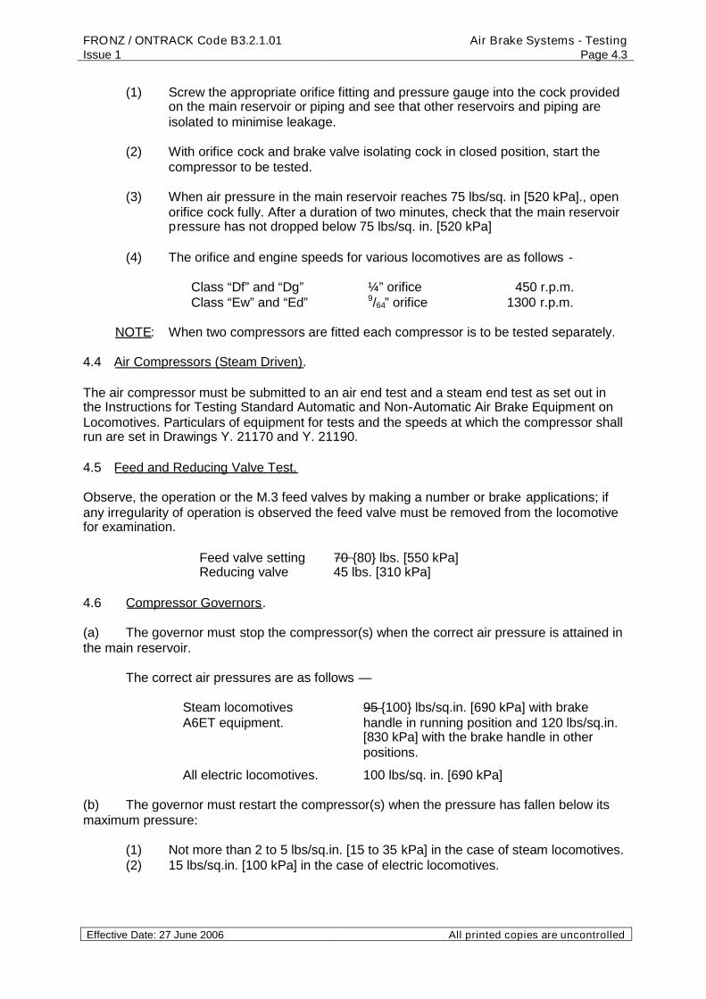
(1) Screw the appropriate orifice fitting and pressure gauge into the cock providedon the main reservoir or piping and see that other reservoirs and piping areisolated to minimise leakage.
(2) With orifice cock and brake valve isolating cock in closed position, start thecompressor to be tested.
(3) When air pressure in the main reservoir reaches 75 lbs/sq. in [520 kPa]., openorifice cock fully. After a duration of two minutes, check that the main reservoirpressure has not dropped below 75 lbs/sq. in. [520 kPa]
(4) The orifice and engine speeds for various locomotives are as follows -
Class “Df” and “Dg” ¼” orifice 450 r.p.m.Class “Ew” and “Ed” 9/64” orifice 1300 r.p.m.
NOTE: When two compressors are fitted each compressor is to be tested separately.
4.4 Air Compressors (Steam Driven).
The air compressor must be submitted to an air end test and a steam end test as set out inthe Instructions for Testing Standard Automatic and Non-Automatic Air Brake Equipment onLocomotives. Particulars of equipment for tests and the speeds at which the compressor shallrun are set in Drawings Y. 21170 and Y. 21190.
4.5 Feed and Reducing Valve Test.
Observe, the operation or the M.3 feed valves by making a number or brake applications; ifany irregularity of operation is observed the feed valve must be removed from the locomotivefor examination.
Feed valve setting 70 {80} lbs. [550 kPa]Reducing valve 45 lbs. [310 kPa]
4.6 Compressor Governors.
(a) The governor must stop the compressor(s) when the correct air pressure is attained inthe main reservoir.
The correct air pressures are as follows —
Steam locomotivesA6ET equipment.
95 {100} lbs/sq.in. [690 kPa] with brakehandle in running position and 120 lbs/sq.in.[830 kPa] with the brake handle in otherpositions.
All electric locomotives. 100 lbs/sq. in. [690 kPa]
(b) The governor must restart the compressor(s) when the pressure has fallen below itsmaximum pressure:
(1) Not more than 2 to 5 lbs/sq.in. [15 to 35 kPa] in the case of steam locomotives.(2) 15 lbs/sq.in. [100 kPa] in the case of electric locomotives.

FRONZ / ONTRACK Code B3.2.1.01Issue 1
Air Brake Systems - TestingPage 4.4
Effective Date: 27 June 2006 All printed copies are uncontrolled
(c) In the case of Single Head Governors the brake valve isolating cock is to be closedand the governor adjusted to stop the compressor when the main reservoir pressure reaches95 lbs/sq.in. 100 psi [700 kPa]
(d) (1) With Double Headed Governors the brake valve isolating cock is closed, theautomatic brake handle placed in lap position, and the high pressure headadjusted to stop the compressor when the main reservoir pressure reaches 120lbs/sq.in. [830 kPa]
NOTE: It is important that the high pressure head of the governor be set first and willensure that the low pressure head can be set correctly, which will be impossible in theevent of the high pressure head setting being below 95 lbs/sq.in. 100 psi [700 kPa].
(2) When the high pressure head is set, the automatic brake valve handle is placedin running position and the main reservoir pressure reduced to about 90 lb/sq.in. [620 kPa] The low pressure head is then set to stop the compressor whenthe main reservoir pressure reaches 95 lbs/sq.in. 100 psi [700 kPa]]
(e). The independent brake handle shall at all times be in its running position.
4.7 Brake Pipe Leakage Test.
To test for brake pipe leakage, make a 10 lb. [70 kPa] “Service” reduction and “Lap” the brakevalve handle. Observe the fall in brake pipe pressure as indicated by brake pipe pressuregauge. The leakage must not exceed 2 lbs. per minute.
4.8 Automatic Brake Valve Test.
(a) The handle of the automatic brake valve must operate easily, and the lift of rotaryvalve spindle must not exceed 1/8”.
(b) Test rotary valve leakage by making a 20 lb. [140 kPa] reduction and “Lap” brakevalve handle. Observe during a period of one minute, that the brake pipe pressure does notincrease more than 2½ lbs., [15 kPa]or the brakes release.
(c) Place the automatic brake valve handle in “Lap” position and observe the equalizingreservoir gauge. See that the ‘Minimum Reduction” and “Equalizing” feature are functioningcorrectly and that and equalizing reservoir reduction of 6 to 8 lbs. [40 to 55 kPa] is indicatedon the gauge. The brake cylinder gauge should indicate a pressure of 10 to 15 lbs. [70 to 100kPa].
(d) Make a number of small reductions and note that the equalizing piston lifts promptlyafter movement of brake valve handle to “Service” position and seats promptly upon return to“Lap” position. Observe by the pressure gauge that the equalizing piston again opens thedischarge valve with an indicated service reduction of not more than 5 lbs. [35 kPa]. Also seethat there is no leak from the brake pipe exhaust port after the equalizing discharge valveseats.
(e) Place the automatic brake valve in “Emergency” position, and observe that the brakepipe pressure falls at a rapid rate, also that a continuous discharge of air occurs at theexhaust port. See that the usual increase in brake cylinder pressure over that obtained with aService application is obtained, and that the safety valve on the distributing valve is blowing.
Check that sanding equipment operates (not “Ed” class and steam locomotives).
FRONZ / ONTRACK Code B3.2.1.01Issue 1
Air Brake Systems - TestingPage 4.5
Effective Date: 27 June 2006 All printed copies are uncontrolled
Emergency application 0 - 55 lb. [380 kPa] = 10 seconds.
4.9 Independent Brake Valve Test.
(a) The handle of independent brake valve must operate easily, and the lift of rotary valvespindle must not exceed 1/8”. The brake valve handle must return from “Quick” Applicationand “Quick” Release to “Slow” Application and “Running” Position respectively when thehandle is released.
(b) Test rotary valve leakage by making a 20 lb. independent application; “Lap” brakevalve handle, and the brake cylinder pressure must not increase more than 5 lbs. [35 kPa] perminute.
(c) Place independent brake valve handle in (1) “Quick” Application, (2) “Slow” Applicationand see that a maximum brake cylinder pressure of 45 lbs. [310 kPa] is indicated. “Lap” brakevalve handle end observe over a period of 1 minute that the brakes do not leak off.
“Quick” Application 0 - 45 lbs. [310 kPa] = 5 seconds max.“Slow” Application 0 - 45 lbs. [310 kPa] = 10 seconds max.
(d) Place independent brake valve handle in (1) Release (2) Running position and thebrakes must release. Release Rate 45 - 10 lbs. in 5 seconds max. for both positions.
(e) Make a service application with the automatic brake valve and place the handle in“Lap” position. Move independent brake valve handle to “Release” position. See that thebrakes release and that the independent “Warning” air discharge occurs at the exhaust port.Return the independent brake valve handle to ‘Running” position for 1 minute and the brakesmust not re-apply.
4.10 Equalizing Reservoir Control Valve Test.
Place the automatic brake valve handle in “Service” position until both brake pipe andequalizing reservoir pressures are reduced to zero, then place brake valve handle in“Running” position. With a constant brake pipe pressure of 80 lbs., note the time required tocharge the equalizing reservoir to 60 lbs. [415 kPa] This must not be less than 54 seconds ormore than 64 seconds.
4.11 Distributing Valve Test.
(a) Check for leakage at exhaust port of distributing valve in the application and releaseposition. No leakage allowed.
During the brake valve test No. 8 and 9, any defects in the operation of the distributingand independent release valve can be the cause of the tests not being satisfactory.
With reference to the distributing valve, leakage or blow at distributing valve exhaust inrelease position only, indicates application valve or application valve cage sealleakage. Leakage in application position, indicates exhaust valve leakage.
(b) Place the automatic brake handle in “Emergency” position and observe on the brakecylinder gauge, the pressure at which the safety valve on distributing valve opens. This shouldbe 55 lbs. [380 kPa]. Return brake valve handle to “Lap” position and note the closingpressure of the safety valve, which should be within 3 lbs. of the opening pressure.

FRONZ / ONTRACK Code B3.2.1.01Issue 1
Air Brake Systems - TestingPage 4.6
Effective Date: 27 June 2006 All printed copies are uncontrolled
4.12 Brake Valve Isolating Cock Test.
To test for brake valve isolating cock leakage make a 10 lbs. [70 kPa] service reduction, closethe isolating cock, and the brake pipe pressure must not increase when the brake valvehandle is placed in “Running” position. (1 minute test).
4.13 Brake Cylinder Leakage Test
Make an independent brake valve application and when 45 lbs. [310 kPa] brake cylinderpressure is obtained close the main reservoir supply cock to the distributing valve. The brakecylinder leakage must not exceed 5 lbs. [35 kPa] per minute.
Open main reservoir supply cock when test is completed, and check brake operation.
4.14 Test Main ReservoirSafety Valve. (If fitted)
Close the 3/8” isolating cock main reservoir supply to the compressor governor, and allow themain reservoir air pressure to build up until the safety valve blows. Safety valves must beadjusted to the specified setting.
NOTE: When two safety valves are fitted each one is to be tested separately.
4.15 Brake Pipe Application Test.
With both brake valve handles in Running position, open each brake pipe cock in turn at endof locomotive and see that the brakes apply, and release when the cock is closed.
Check signal trip, if fitted.
4.16 Dead Man’s Application Test.
Move master switch to “ON” position and press dead man’s pedal down, release pedal andthe brake must start to apply between 5 - 7 seconds. When the brakes are applied, they mustrelease when the pedal is pressed down.
4.17 General Inspection.
(a) Examine brake rigging, check piston travel and hand brake.(b) Examine slack adjusters (when fitted).(c) Check operation of sanding equipment (Manual and Electric).(d) Operate horn end window wipers.(e) Check low main reservoir pressure buzzer.(f) Check dead engine device.(g) Check control air pressure. 70 lbs. [480 kPa](h) Check operation of control circuit governor.
4.18 Dynamic Brake Test (Diesel Electric Locomotives only).
With engine running move master switch to “ON’ and reverser handle to forward or reverse.Move the control handle to “L” then to “B” end observe the Driving Ammeter for movement.Apply the independent brake and note that the dynamic brake is suspended as soon as thebrake cylinder pressure rises to 23 lbs [160 kPa]. Return controls to “OFF” position.
NOTE: This test is to be made for only a short duration.

FRONZ / ONTRACK Code B3.2.1.01Issue 1
Air Brake Systems - TestingPage 4.7
Effective Date: 27 June 2006 All printed copies are uncontrolled
4.19 The distributing valve, brake pipe, piston travel and brake cylinder leakage tests canbe carried out on a “dead” engine by means of the single vehicle testing device — seestandard test code for Automatic and Non-automatic brake equipment on Locomotives.

FRONZ / ONTRACK Code B3.2.1.01Issue 1
Air Brake Systems - TestingPage 5.1
Effective Date: 27 June 2006 All printed copies are uncontrolled
Section 5Brake System Testing
Testing Steam Driven Air Compressors
Source MaterialNew Zealand Railways - Steam Driven Air Compressors (Extract only) - 28 April 1958
ContentsSection Page
5.1 Steam End Test 5.15.2 Air End Test 5.1
Table A - Steam End Test For Running Sheds 5.2Table B - Air End Test 5.2
5.1 Steam End Test.
This is a test of the performance of the top head and steam cylinder of the compressor andmust be made with the steam valve to the compressor in the fully opened position.
Main reservoir pressure during this test is to be maintained at 75 lbs/sq.in. [520 kPa]. This iscarried out by opening and adjusting the cock provided on the reservoir and the air allowed toescape until the main reservoir pressure is steady at 75 lbs/sq.in. [520 kPa].
The number of single strokes must then be counted and must not be LESS than that shownfor the particular compressor on Table A, page 5.2 (or the appropriate Running Shed tableson Drawing Y.21190). The test is made for a period of one minute.
If the compressor under the conditions laid down is unable to at least equal the number ofstrokes shown in the table it is to be regarded as having failed in the test.
Defects that should be looked for are, leaking steam piston rings or gaskets, defective mainslide valve or reversing valve, insufficient lubrication, etc.
5.2 Air End Test.
This test checks the performance of the air end of the compressor.
The appropriate orifice (see Drawing Y21170) must be firmly screwed into the cock providedon the reservoir and it should be ascertained that no leakage occurs at the joint. The orificecock should then be opened fully and the steam supply to the compressor so regulated that asteady air pressure of 60 lb./sq.in. is maintained in the reservoir with the air escaping throughthe orifice.
Before making any reading the air pressure should be watched for one minute to ensure itremains steady after adjustment of the steam valve.
With the compressor maintaining the air pressure steady at 60 lbs./sq.in. [415 kPa] againstthe orifice opening, the number of single strokes made during the period of one minute is tobe recorded.
The number of single strokes made by the compressor under the above conditions must thenbe compared with the particular compressor on Table B, page 5.2 (or the appropriate RunningShed tables on Drawing Y.21190). If this maximum number of strokes has not beenexceeded, the compressor may be considered to have passed the Air End Test.

FRONZ / ONTRACK Code B3.2.1.01Issue 1
Air Brake Systems - TestingPage 5.2
Effective Date: 27 June 2006 All printed copies are uncontrolled
Should the number of strokes be exceeded, the air end of the compressor is defective andmay be due to faulty air piston packing rings, piston rod packing, air valves or gaskets leaking.
Table A
Steam End Test For Running Sheds
Minimum No. Of Single Strokes Per Minute Against 75 Lbs Per Square Inch [520 kPa] AirPressure
Steam Pressure In Lbs Per Square InchSize Of
Compressor150 155 160 165 170 175 180
10” x 105/8” 77 80 82 84 86 88 9010” x 10” 87 90 92 94 96 98 1008” x 8½ “ 95 97 99 101 103 105 1078” x 7½ “ 130 133 136 139 142 145 148
7” Cross Cpd. 96 99 102 105 107 109 111
Table B
Air End Test
“A” Test (Running Shed)Maximum number of single strokes per minute against 60 Lbs Per
Square Inch [420 kPa] Air PressureSize Of Compressor Size Of
OrificeMaximum Single Strokes
Per Minute
10” x 105/8”7/32” 158
10” x 10” 13/64” 1588” x 8½ “ 11/64” 1588” x 7½ “ 9/64” 158
7” Cross Cpd. ¼” 158
Tables extracted from Drawing Y 21190 - W.H.B. Steam Driven Air Pumps Speed Tables ForTests
FRONZ / ONTRACK Code B3.2.1.01Issue 1
Air Brake Systems - TestingPage 6.1
Effective Date: 27 June 2006 All printed copies are uncontrolled
Section 6Standard Test Code for Brakes and Air Operated Equipment
On Railcars (Except Silver Fern)
Source MaterialStandard Test Code prepared by Jim Nichols, NZ Railways Vehicle Inspector, from old railcarbrake codes.
Contents
Section Page
6.1 Introduction 6.2
6.2 Test 1 Charging 6.2
6.3 Test 2 Pressure gauges 6.2
6.4 Test 3 Main Reservoir Leakage 6.2
6.5 Test 4 Compressor Governor Settings 6.2
6.6 Test 5 Air Compressor Orifice 6.2
6.7 Test 6 Main Reservoir Safety Valve 6.3
6.8 Test 7 Brake Valve 6.3
6.9 Test 8 Emergency System, Service Brake Piping andBrake Cylinders
6.3
6.10 Test 9 Throttle and Deadmans Pedal 6.4
6.11 Test 10 Water Raising Equipment 6.4
6.12 Test 11 Air Pressure Switches and Alarms 6.4
6.13 Test 12 General 6.5

FRONZ / ONTRACK Code B3.2.1.01Issue 1
Air Brake Systems - TestingPage 6.2
Effective Date: 27 June 2006 All printed copies are uncontrolled
6.1 Introduction
A locomotive is to be given this code test prior to ‘Passing Out” after major servicingand when called for in the servicing schedule or when doubt exists as to the correctingfunctioning of the brake equipment.
When a vehicle has two sets of controls then the test must be repeated for each set.
Test gauges must be tested annually for accuracy by a certified testing agency.
All test equipment must be kept in suitable containers to prevent damage betweenuse.
6.2 Test 1: Charging
Ensure thatMain reservoirs are drainedOil level is correct in the compressor(s)Compressor belt tensions are correct
Start the compressor and note the pressure rises steadily with no undue noise orvibration.
With the throttle closed and the engine speed set to correct value (580 … 620 rpm)measure the time taken to charge the main reservoir from 0 to 400 kPa (0 to 60 psi)
Maximum times areVulcan railcars 9 minutesStandard railcars 13 minutes
6.3 Test 2 : Pressure Gauges
Connect test gauges to the coupling hoses (MR, EP, BC/SA) and suitable pointon the control reservoir or piping.
Cab gauges (both ends) must correct to within ± 20 kPa of indicated pressureson test gauges at maximum working pressure.
6.4 Test 3 : Main Reservoir Leakage
(1) Stop compressor and adjust main reservoir pressure to 550 kPa (80psi), place brake valve handle in “handle off” position. Main reservoir pressuremust not drop more than 20 kPa (3 psi) in one minute and any leakage must bereduced to this amount before continuing with test.
6.5 Test 4 : Compressor Governor Settings
The compressor should load when the main reservoir pressure has dropped to600 kPa (85psi) and unload when the pressure has risen to 700 kPa (100 psi).
6.6 Test 5 : Air Compressor Orifice Test
On railcars fitted with more than one compressor each compressor is tested separately.
(1) Screw the appropriate orifice into the main drain or cock.

FRONZ / ONTRACK Code B3.2.1.01Issue 1
Air Brake Systems - TestingPage 6.3
Effective Date: 27 June 2006 All printed copies are uncontrolled
(2) With main reservoir adjusted to the test pressure and the engine speed or compressorspeed adjusted to the rpm indicated, open orifice cock fully. The compressor must maintainthe test pressure for a period of two minutes. Failure to do so indicates a defectivecompressor.
(3) The orifice size, test pressure, engine or compressor speed for various locomotivesare as follows:
Compressor Orifice Test Pressure Engine Speed4E26 1.6 mm (1/16 in) 400 kPa (60 psi) IdleE13C 1.2 mm (3/64 in) 400 kPa (60 psi) Idle
Faults may include - insufficient lift in valves or leaking air valves, brokensprings, piston rings or gaskets leaking.
6.7 Test 6: Main Reservoir Safety Valve Test
Isolate the governor check main reservoir safety valve(s) setting. It should open at 750kPa (110 psi).
6.8 Test 7: Brake Valve
(1) With system charged, move brake handle to full service position. Brakecylinder pressure must rise from 0 to 300 kPa (45 psi) in not more than 2.5seconds.
(2) Move brake handle to relapse position. Brake cylinder pressure mustfall from 300 to 75 kPa (45 to 10 psi) in not more than 3.5 seconds.
(3) Move the brake valve in steps towards full service position and notethat 50 kPa (5 – 10 psi) increments of brake cylinder pressure can be obtained.
Full pressure should be 350 kPa (50 psi).
(4) Move brake valve towards release in steps and note that brake cylinderpressure can be decreased in 50 kPa (5 – 10 psi) steps.
(5) Check that the brake handle operates smoothly without stiffness orexcessive chattering.
(5) Move handle to emergency position and note that the emergency pipepressure falls rapidly to zero.
(6) Move brake handle slowly away from emergency and note that at least12 mm (½ “) movement is made before the emergency pipe starts to charge.The time taken to charge the pipe from 0 to 400 kPa (60 psi) should not exceed25 seconds.
6.9 Test 8:Emergency System, Service Brake Piping and Brake Cylinders
(1) Place brake valve in full service position and check relay valve exhaustfor leakage. Only a small bubble is allowed.

FRONZ / ONTRACK Code B3.2.1.01Issue 1
Air Brake Systems - TestingPage 6.4
Effective Date: 27 June 2006 All printed copies are uncontrolled
(2) Block down deadmans pedal, release brakes, close straight air andemergency cocks to all bogies. Check relay valve exhaust for leakage. Only asmall bubble is allowed.
Each bogie is to be tested separately.
(3) On the bogie being tested, drain emergency reservoir, fit pressuregauge to the reservoir, open emergency cock and note time to charge reservoirfrom 0 to 400 kPa (60 psi). This must not exceed
Vulcan railcars 110 secondsOther railcars 80 seconds
(4) With reservoir charged to 500 kPa (70 psi) make an emergencyapplication and check blocks press firmly on all wheels.
(5) Check that the pressure holds steady with leakage not exceeding 35kPa (5 psi) over one minute.
(6) Open straight air isolating cock to bogie being tested and place brakevalve in release position. When the emergency pipe pressure is raised above35 kPa (5 psi), the emergency valve must exhaust air at relay valve.
(7) With reservoir charged, move brake handle to service position until 350kPa (50 psi) is built in brake cylinders. Move brake handle to emergencyposition and the brake cylinder will rise, causing the safety valve to lift. Thisshould open at 425 kPa (60 psi).
(8) Charge system. With deadman pedal depressed move the brakehandle to handle off position, pausing to allow 150 kPa (20 psi) brake cylinderpressure to build up. Check that the emergency pressure does not drop morethan 15 kPa (2 psi) over one minute.
6.10 Test 9: Throttle and Deadmans Pedal
(1) Place test gauge on throttle pipe headstock hose, apply straight airbrake fully, all deadmans pedals released. Open throttle and note that enginespeed increases. Close throttle and note that engine speed decreases.
(2) Open throttle to ¾ engine speed on Standard and Vulcan railcars.Release the brake and deadmans pedals to vent the emergency pipe. Notethat the engine speed returns to idle.
(3) With brake applied, open throttle valve fully and check the pressure inthe throttle pipe. This should be 375 kPa (55 psi). Check auxiliary valve forleakage at both ports.
6.11 Test 10: Water Raising Equipment
Connect test pressure gauge to air line. Pressure should be between 50 and 70 kPa (7 to 10psi).

FRONZ / ONTRACK Code B3.2.1.01Issue 1
Air Brake Systems - TestingPage 6.5
Effective Date: 27 June 2006 All printed copies are uncontrolled
6.12 Test 11: Air Pressure Switches and Alarms
(1) Check that the air pressure alarms and switches operate.
(2) Low main reservoir switch should cut out at 525 kPa (75 psi).
(3) Emergency pipe pressure switch should operate at 300 kPa (55 psi)
(4) Control air pressure switch should operate at 375 kPa (55 psi)
(5) Straight air brake pressure switch should operate at 75 kPa (10 psi)
6.13 Test 12: General
(1) Check that the passengers and guards emergency stop valves operate.
(2) Check that the sanding equipment operates correctly with pipes alignedwith the rails.
(3) Check that the horns and window wipers operate correctly.
(4) Test the handbrake operation. With handbrake on the railcar should notmove when in 1st gear. Note the number of turns to operate the handbrake.
(5) Check the condition of the brake rigging.
(6) Check that the brake piston travel is within limits for the type.

FRONZ / ONTRACK Code B3.2.1.01Issue 1
Air Brake Systems - TestingPage 7.1
Effective Date: 27 June 2006 All printed copies are uncontrolled
Section 7Brake System Testing
6SL Locomotive Brakes
Source MaterialTranz Rail Ltd M9103 - Standard Test Code, Locomotive Brake All Classes (Except Ef) - Sep
1996(First Issued as Code Ml 1-7 September 1990. Reissued June 1995)
Steam Incorporated – COP 08; Air Brake Code For Diesel Locomotives; 24/08/1998NZ Railways – Air Brake HandbookVarious test forms and notes
Contents
Section Page
7.1 General 7.2
7.2 Test 1 Charging 7.2
7.3 Test 2 Pressure Gauges 7.2
7.4 Test 3 Compressor Governor Setting 7.2
7.5 Test 4 Main Reservoir Leakage 7.3
7.6 Test 5 Main Reservoir Check Valve 7.3
7.7 Test 6 Brake Pipe Leakage 7.3
7.8 Test 7 Air Compressor Check 7.3
7.9 Test 8 Feed Valve 7.3
7.10 Test 9 Auto brake valve 7.3
7.11 Test 10 Independent Brake 7.4
7.12 Test 11 Distributing Valve 7.5
7.13 Test 12 Dynamic Brake Interlock 7.5
7.14 Test 13 Brake Cylinder Leakage 7.5
7.15 Test 14 Brake-in-two 7.5
7.16 Test 15 Main Reservoir Safety Valve 7.6
7.17 Test 16 Vigilance Control 7.6
7.18 Test 17 General 7.7

FRONZ / ONTRACK Code B3.2.1.01Issue 1
Air Brake Systems - TestingPage 7.2
Effective Date: 27 June 2006 All printed copies are uncontrolled
7.1 General
A locomotive fitted with a 6SL brake system is to be given this code test prior to‘Passing Out” after major servicing and when called for in the servicing schedule orwhen doubt exists as to the correcting functioning of the brake equipment
When a locomotive has two sets of controls then the test must be repeated for eachset.
The brake valves must be returned to the release position at the completion of eachtest.
Not all locomotives are fitted with all the equipment covered by this test code.
Test gauges must be tested annually for accuracy by a certified testing agency.
All test equipment must be kept in suitable containers to prevent damage betweenuse.
A manifold, which couples the master gauge to the various pressure sources, may beused for the code test.
7.2 Test 1: Charging
Ensure that main reservoirs are drained, that oil level is correct in the compressor, thatbrake valve cut-off cock (3 way cock) is at the “Lead” position. All brake valves in thecab being tested should be in release position.
Start the compressor and note the pressure rises steadily with no undue noise orvibration.
7.3 Test 2 : Pressure Gauge
(4) Main Reservoir: Place standard test gauge on MR hose at headstock or drainfrom reservoir or at test location point if provided. Full pressure on locomotivegauges must be correct to within ± 20 kPa of indicated pressure on test gauge.
(5) Brake pipe and equalising reservoir: Place standard test gauge onto BP hoseat headstock. Pressure on locomotive gauges must be correct to within ± 15kPa of test gauge at 550 kPa. Leave test gauge on until all tests arecompleted.
(6) Brake cylinder: Place test gauge on brake cylinder equalising hose or controlpipe at headstock or onto brake cylinder delivery line. Make a full serviceapplication with independent brake valve and compare locomotive gauge withtest gauge at 350 kPa. Pressure must be within ±10 kPa.
7.4 Test 3 : Compressor Governor Setting
6SL locomotive governors must load the compressor when the main reservoirpressure has dropped to 875 kPa and unload when the pressure has risen by 75 kPato 100 kPa. Locomotives fitted with a governor having the differential readily adjustedshould be set at 100 kPa differential.

FRONZ / ONTRACK Code B3.2.1.01Issue 1
Air Brake Systems - TestingPage 7.3
Effective Date: 27 June 2006 All printed copies are uncontrolled
7.5 Test 4 : Main Reservoir Leakage
(3) Stop compressor and adjust main reservoir pressure to 550 kPa, place brakevalve cut-off cock into “Dead” position. Main reservoir pressure must not dropmore than 20 kPa in one minute and any leakage must be reduced to thisamount before continuing with test. On remote control locomotives set the cutover cocks to manual.
(4) On locomotives fitted with a check valve between No.1 and No.2 reservoirs theleakage must be observed on both sides of valve. Couple the standard testgauge to No. 1 main reservoir unless the locomotive is fitted with a gauge onthe line from the compressor to No.1 reservoir.
7.6 Test 5 : Main Reservoir Check Valve
Blow down the pressure in No.1 reservoir as shown by the test gauge to about 200kPa below the pressure in No.2 reservoir as shown in cab gauge. Time over 1 minute,pressure in No.2 reservoir should not drop greater than 50 kPa in 1 min. No.1 reservoirshould not rise greater than 50 kPa. This would indicate a defective check valvebetween reservoirs.
7.7 Test 6 : Brake Pipe Leakage
Make a 75 kPa brake pipe reduction and leave the brake handle in “Lap”.. Place cut-out cock in “Dead” position. Brake pipe pressure must not drop more than 15 kPa inone minute. Leakage must be reduced to that amount before continuing the tests.Note the brake pipe pressure must not rise during the one minute.
7.8 Test 7 : Air Compressor Check
(4) Screw the appropriate orifice into the main reservoir drain or MR headstockcock hose.
(5) With main reservoir adjusted to the test pressure and the engine speed orcompressor speed adjusted to the rpm indicated, open orifice cock fully. Thecompressor must maintain the test pressure for a period of two minutes.Failure to do so indicates a defective compressor.
Compressor Locomotive Orifice TestPressure
Speed
WBO DFT, DF, DC 5.6 mm 500 kPa Idle
7.9 Test 8 : Feed Valve
Check operation of the feed valve by making several automatic applications andreleases. Brake pipe pressure should settle at 550 kPa each time. If any sluggishnessor irregular operation is evident, the feed valve must be removed for attention.
7.10 Test 9 : Automatic Brake Valve Test
(1) The handle of the brake valve must operate freely and must not be slack on therotary valve spindle. Rotary valve spindle lift must not exceed 3mm.

FRONZ / ONTRACK Code B3.2.1.01Issue 1
Air Brake Systems - TestingPage 7.4
Effective Date: 27 June 2006 All printed copies are uncontrolled
(2) Make a 40 kPa brake pipe reduction. Brake must apply with at least 60 kPa ofbrake cylinder pressure and equalising piston must have lifted prior to 35 kPareduction being reached.
(3) Make a further small reduction of 20 - 25 kPa and note that equalising pistonlifts and re-seats and that brake cylinder pressure rises.
(4) Brake pipe pressure will now be just below 500 kPa. Place brake valve handlein Service and note time to blow down equalising reservoir pressure from 475kPa to 350 kPa. This must not be more than 10 seconds. Note that after eachbrake pipe reduction the equalising piston seats and brake cylinder pressurerises.
(5) With brake pipe pressure at 350 kPa, leave the brake valve in “Lap” and notethat over one minute the brake pipe pressure does not rise more than 15 kPanor the brakes release.
(6) Whilst brake is applied, test for leakage at port D (elbow) on brake valve fillingpiece. Leakage indicates:
Leaking upper valve of FA4 magnet valve.
Leaking equalising slide valve of distributing valve.
Leaking application check valve on independent brake valve.
Leaking valve on dynamic valve.
(7) With brake pipe pressure still at 350 kPa, place cut-out cock in “Trail’ position,return brake valve to running position and check brake pipe over one minute.Pressure should not increase or brake release. Repeat test with cut-out cock in“Dead” position. At completion of tests, place brake valve in “Lap” and cut-outcock in “Lead”.
(8) Recharge system and then move brake valve into “Emergency” position. Notethat brake pipe pressure falls quickly to zero and that brake cylinder pressurerises from 0 - 450 kPa in 3 – 5 seconds. Safety valve must open at 475 kPaand seat when pressure drops to 450 kPa. Check that emergency sand hasoperated.
7.11 Test 10: Independent Brake Test
(6) Move the independent brake valve in steps towards full application position andnote that 50 kPa increments of brake cylinder pressure can be obtained.
Full pressure should be 350 kPa.
(7) Move brake valve towards release in steps and note that pressure can bedecreased in 50 kPa steps.
(8) Quick release test
a. Make a 150 kPa automatic reduction, leaving the handle in “Lap”. Depress theindependent brake handle to quick release position and note that the brakecylinder pressure drops quickly to zero pressure.

FRONZ / ONTRACK Code B3.2.1.01Issue 1
Air Brake Systems - TestingPage 7.5
Effective Date: 27 June 2006 All printed copies are uncontrolled
b. Place automatic brake valve in running position and recharge system. Whencharged, make a 150 kPa automatic reduction then move independent handleto “Full Service”. Depress handle and move to “Release” position. Brakes mustnot release until the handle has reached the depression at the release position.
7.12 TEST 11: Distributing Valve
Check at exhaust port in application and release positions. A slow bubble only isallowed.
Leakage with brake released indicates a leaking application valve.
Leakage with brake applied indicates a leaking exhaust valve.
Note: - During brake valve test, should brakes fail to apply at 40 kPa reduction orshould brake cylinder pressure be abnormally low following a 150 kPareduction, the distributing valve could be defective. If any doubt arises as to thecondition of the distributing valve, it is to be replaced with a tested unit.
7.13 Test 12 : Dynamic Brake Interlock
(1) Make a 100 kPa brake pipe reduction and return the brake valve to LAP.
(2) Place engine ‘on-line’ and Reverser Handle in either direction.
(3) Move selector to B position and wait for cam switch to throw (11 seconds).
(4) Bring throttle handle into braking range and brakes must release and enginespeed increase.
(5) Release dynamic brake and the automatic brake must reapply. (Brake cylinderpressure will be about 25 kPa lower on each re-application.)
7.14 Test 13: Brake Cylinder Leakage Test
(5) Screw test gauge into brake cylinder isolating cock exhaust or test pointprovided.
(6) Make a full application with independent brake valve.
(7) Move isolating cock to isolated position and check reading on gauge.
(8) Pressure drop must not exceed 35 kPa per minute.
(9) Repeat test on other bogie.
7.16 Test 14: Break-In-Two Test:
As Leading Locomotive
(1) Open EP cock at headstock.
(2) Open BP cock until a blow occurs at EP hose.
(3) Open MR cock fully and check that flow at EP hose ceases.

FRONZ / ONTRACK Code B3.2.1.01Issue 1
Air Brake Systems - TestingPage 7.6
Effective Date: 27 June 2006 All printed copies are uncontrolled
(4) Close MR cock and check that blow at EP hose recommences.
Should blow from EP hose not cease when MR cock is opened a fault will befound in the cut out valve or in the check valve and choke.
As Trailing Locomotive
(1) Place the 3 way cock in the “Trail” position.
(2) Open MR, EP and BP cock in turn. Brakes should apply and remain applied forone minute with no blow from the EP hose.
(3) Close MR cock. Air should now flow from EP hose and brakes release.
7.16 Test 15: Main Reservoir Safety Valve Test
Close the compressor governor isolating cock and check the safety valve settings.
Locomotive Lower Valve Upper Valve (if fitted)Da 1025 kPa 1150 kPa
Notes
(1) Test upper valve first. Test by either blanking lower valve (preferred) or setlower valve higher than upper. Remove blanking plate after test.
(2) If adjustment to safety valves is necessary, always replace the cap beforechecking pressure as the valve setting may alter when cap is tightened.
7.17 Test 16: Vigilance Control
All control switches and circuit breakers must be set up as normal power operation.Switch radio circuit breaker OFF (if fitted with alarm call facility).
Pneumatic Vigilance
(1) Check that time cycle from operation of a cancelling switch to sounding ofwarning whistle is 60 - 75 seconds and that emergency warning or brakeapplication occurs after a further delay of no more than 25 seconds.
(2) Check operation of all cancelling switches.
(3) Hold a switch closed and note that the warning whistle sounds on overchargingof the system.
(4) Note that applying locomotive brake fully or placing 3 way valve in “trail” willsuppress the vigilance.
(5) Check that the isolating cock glass is intact and sealed.
Note: - Should the time cycle need adjustment by more than 15 seconds, a pressuregauge must be fitted to the timing reservoir to check operation of the variouspressure switches.

FRONZ / ONTRACK Code B3.2.1.01Issue 1
Air Brake Systems - TestingPage 7.7
Effective Date: 27 June 2006 All printed copies are uncontrolled
Electronic Vigilance
(3) Brake cylinder pressure reduced to below 160 kPa.
(4) Reverser handle placed in forward or reverse position.
Cycle times are not adjustable.
Drivers SideReset to Light 50 seconds ± 3 secondsLight to Whistle 10 seconds ± 2 secondsWhistle to Penalty Brake 10 seconds ± 2 seconds
Assistant’s Side (where fitted)
Buzzer and Light 180 second ± 15 seconds
(5) Time is to be taken from operation of cancelling device to light. From light towhistle or buzzer, from whistle to penalty brake. Wait 47 secs after penaltybrake application. The vigilance system must not reset itself.
(6) Check operation of all cancelling switches.
(7) Hold a switch closed and note that warning whistle or buzzer sounds. (Not onall electronic types)
(8) Note the brake cylinder pressure required to suppress vigilance system isbetween 225 – 250 kPa on rising pressure.
(9) Check that isolating glass is intact and sealed.
7.18 Test 17 : General
(5) Examine brake rigging and piping and hoses. Check piston travel is between40 mm -125 mm.
(6) Check handbrake operation.
(7) Check sanders (in both directions), horns, window wipers.
(8) Check wheel-slip sand delay switch or wheel-slip brake.
(9) Check position of Dead Engine Device handle.
(10) Check control air pressure = 625 +/- 20 kPa.
(11) Check operation of PCS (Pressure Control Switch).
Open 250 kPaClose 375 kPa

FRONZ / ONTRACK Code B3.2.1.01Issue 1
Air Brake Systems - TestingPage A.1
Effective Date: 27 June 2006 All printed copies are uncontrolled
Appendix ABrake System TestingSample Record Sheets
Contents
Section PageIntroduction A.1Principles A.1Sample formsFRONZ/ONTRACK - Air System Test Record - Passenger Cars and ServiceVehicles
A.2
Taieri Gorge Railway - Dj Locomotive Brakes - Test RecordMainline Steam Trust - MSHT 002 - Test Results for A6ET BrakeDiesel Traction Group - De Locos - Brake Test ReportFRONZ/ONTRACK - Railcar Air Brake Test Record
IntroductionThe Appendix includes several sample record sheets as used by existing Heritage NetworkOperators. They have not been verified as complying with the approved codes.
PrinciplesIn preparing a record sheet the following principles should be followed.
The record sheet should include reference to the code being used.The layout should follow the code being used to reduce the chance of confusion.The tests should show minimum and /or maximum limits for the test or what needs to
be verified.The date of the test, vehicle ID and vehicle type must be recorded.The name and signature of the person doing the test must be recorded.
Sample Forms

FRONZ / ONTRACK Code B3.2.1.01Issue 1
Air Brake Systems - TestingPage A.2
Effective Date: 27 June 2006 All printed copies are uncontrolled
Air System Test RecordPassenger Cars and Service Vehicles
(Extract from FRONZ / ONTRACK Inspection Record B3.1.6.21)
Vehicle ID Vehicle OperatorAir Tests
Initial chargingCharge brake system to 550 kPa. No audible leaks in piping and equipment
Brake pipe leakage (at 550 kPa)Max = 15 kPa in 1 min (Must be below this before continuing tests) kPaPiston travel and rigging (150 kPa reduction in brake pipe pressure)Travel. Limits = 150 – 165 mm for auto slack adjusters, 125 to 200 mm for manual. mmNo audible leaks at cylinderAll rigging and levers at correct angles. Will not foul as the blocks wear.
HandbrakeApplies. (Lever type should not bottom.)No of turns (6 – 8 for auto slack adjuster, 5 – 10 for manual adjuster, 1 – 6 for van) turnsAutomatic Slack Adjuster (when fitted) (Pneumatic or SAB type)(Screw adjuster out to test)No audible leaks at 150 kPa reduction (pneumatic type only)Adjuster rotates when brakes release
Minimum Reduction (40 kPa reduction)Brakes remain applied for 1 min.Nil or only slight air blow at triple exhaust
Slow Release Test (brakes released from 75 kPa reduction)Time to release through 0.58 mm choke. Max = 25 secs for 1¼” train pipe, 15 secsfor 1” train pipe
secs
Nil or only slight air blow at triple exhaust after brakes fully released.
Passenger Emergency Valve Test (brakes charged to 550 kPa)Brakes apply – No 1 valveBrakes apply – No 2 valve
Release Valve (at 150 kPa reduction)With cock open, air exhausts and brakes release. Cock closes when released.
With train pipe pressure exhausted, cock remains open (auto type only)
Brake pipe leakage (at 550 kPa)Max = 15 kPa in 1 min (Must be below this before continuing tests) kPaBrake Pipe Maintenance and Auxiliary LeakageBrakes remain applied for 10 minutes at 75 kPa reduction.
Air Test Completed and system is FIT / NOT FIT for service (delete one):-
Name Date / /
Signature Depot

TAIERI GORGERAILWAY LTD
DJ LOCOMOTIVE BRAKESTEST RECORD
6 May 2002Page 1 of 2
Effective Date: 27 June 2006 All printed copies are uncontrolled
Locomotive DJ Date of Test
Use with Code 633 - Standard Code - Dj Locomotive - Air Brake & Equipment Test
Test Limits Measured Pass Fail
1 Compressor charges correctly.
Pressure gauges– Main reservoir
± 20 kPa @ full press kPa
- Brake pipe ± 15 kPa @ 550 kPa kPa
- Equalising reservoir ± 15 kPa @ 550 kPa kPa2
- Brake cylinder ± 10 kPa @ 350 kPa kPa
Governor settings - Cut in @ 725 kPa kPa3
- Cut out @ 800 – 825 kPa kPa
Main reservoir leakage - No 1 20 kPa in 1 min kPa4
- No 2 20 kPa in 1 min kPa
Reservoir check valve - No 1 + 50 kPa in I min kPa5
- No 2 - 50 kPa in I min kPa
6 Brake pipe pressure +0 / - 15 kPa in 1 min kPa
7Air compressor
(6.4 mm @ idle) 500 kPa for 2 mins kPa
BP 40 – 50 kPa kPaAutomatic brake valve- Minimum reduction
BC applies (<100 kPa) kPa
- Incremental application
BP ≈390 kPa kPa- Full service
BC 425 – 450 kPa kPa
- Suppression No reduction in BP
- Handle offBP & ER drop @ servicerate. BP ≈75 kPa kPa
- Release – intermediatepositions
No release
ER 375 → 525 kPa < 3 sec sec- Full release
BC 350 → 25 kPa < 9 sec sec
BP & ER fall rapidly
BC 0 → 350 kPa in 6–9 sec sec
8
- Emergency
BC ≈440 kPa max kPa
B.P. – 25 kPa kPa
B.C. + 60 kPa kPa9 Brake pipe maintaining feature( 4.8 mm orifice)
Steady over 1 minute

TAIERI GORGERAILWAY LTD
STANDARD CODEDJ LOCOMOTIVE BRAKES
6 May 2002Page 2 of 2
Effective Date: 27 June 2006 All printed copies are uncontrolled
Test Limits Measured Pass FailBP apply in 50 kPa stepsIndependent brake valve
- ApplicationBC = 350 kPa kPa
- Release BP decrease in 50 kPa step
- Double check valve Ind. holds 150 – 200 kPaafter auto release.
10
- Quick release BC drops rapidly to 0 kPa
Auto brakes do not apply inservice position11 Cut off valve (cut-out)Brakes apply in emergency
12 MU2A valve (Trail 6 or 26) Ind brakes do not apply
Opens @ 175 kPa rising kPa13 Dynamic interlock
Closes @ 150 kPa falling kPa
Brake cylinder leakage - Bogie 1 kPa
- Bogie 2 kPa14
- Bogie 3
35 kPa in I min.
kPa
15 Break in two (open all BP cocks in turn)
16 Main reservoir safety valve 900 kPa kPa
Vigilance System- Drivers - Reset to light
50 secs ± 3 ses secs
- Light to whistle 10 secs ± 2 secs secs
- Whistle to penalty brake 10 secs ± 2 secs secs
- Penalty brake reset Must not self reset (wait 47 s)
- Suppression pressure 225 – 250 kPa kPa
- Assistants - reset to light secs
- Light to buzzer
180 secs ± 15 secs(total cycle) secs
17
- General - all switches cancel / glass intactGeneral – Brake rigging / hoses / piston travel (40 – 125 mm) /
handbrake / sand / horns / wipers
- Main reservoir auto drain
Open 250 kPa kPa18
- CCGClose 375 kPa kPa
19 Main reservoir protection 600 kPa kPa
NameThis vehicle’s brake system has been inspected inaccordance with Code 633 and is:-
FIT / NOT FIT for service. (delete one) Signature

Mainline Steam TrustMSHT 002 Test Results for A6ET Brake
Effective Date: 27 June 2006 All printed copies are uncontrolled
__Locomotive _____________ Date ________________
1.Charging -See that all reservoirs have been drained.Start compressor and note that pressure rises steadily and the compressor operates
evenly without undue noise or vibration.Fit a standard pressure gauge to the brake pipe and leave on for tests.
2. Pressure Gauges-Check all brake gauges against the standard test gauge, gauges must be correct
within + or - 15kpa.( 3psi )PASS / FAIL
3. Main Reservoir Leakage-Stop the compressor and adjust main reservoir pressure to 550 kpa ( 80psi ). Close
brake valve isolating cock.Main reservoir pressure must not drop more than 20kpa ( 3psi ) per minute and
leakage must be reduced to this amount before continuing the tests.PASS / FAIL LEAKAGE____________per/min
4. Brake Pipe Leakage-With the Brake valve isolating cock still closed make a 75kpa (10 psi ) brake pipe
reduction leaving the brake valve handle lapped.Brake pipe pressure must not drop more than 15kpa ( 2psi ) per minute and leakage
must be reduced to this amount before continuing with the tests.PASS / FAIL LEAKAGE_____________per/min
5. Compressor Governor-On all locomotives the governor must load the compressor when the main reservoir
pressurehas fallen to 655kpa ( 95psi ) and unload at 690kpa ( 100psi )
PASS / FAIL RESET REQUIRED Y/N
Place the Automatic Brake valve handle in the minimum reduction position, the mainreservoir pressure must rise to 828kpa ( 120psi )
PASS / FAIL RESET REQUIRED Y/N
6. Feed and Reducing Valves-Check operation of M3 valves by making several automatic reductions and releases.
Brake pipe pressure must return to 550kpa ( 80psi ) each time.PASS / FAIL RESET REQUIRED Y/N
Make several full independent applications and releases. Brake cylinder pressuremust rise to 350kpa ( 50psi ) each time.
PASS / FAIL RESET REQUIRED Y/N
7. Automatic Brake Valve Test-The handle of the brake valve must operate freely and must not be slack on the rotary
valve spindle. Rotary valve lift must not exceed 3mm.PASS / FAIL
Place Automatic brake valve in LAP position and note equalising reservoir gauge.See that MINIMUM REDUCTION feature functions correctly and that an equalisingreservoir reduction of 40-55kpa ( 6-7psi ) occurs and that brake cylinder pressureindicates 75-100 kpa ( 10-14psi ).
PASS / FAIL REDUCTION _________CYLINDER PRESSURE _________
PAGE 2

Mainline Steam TrustMSHT 002 Test Results for A6ET Brake
Effective Date: 27 June 2006 All printed copies are uncontrolled
7.continPlace handle in SERVICE note that the equalising piston lifts promptly and that
equalising reservoir pressure reduces from 475 to 350kpa ( 70 to 50psi ) in not morethan 10 seconds.
Lap the brake valve when pressure is reduced to 350kpa ( 50psi ).PASS / FAIL TIME ________ SEC
Note that there is no blow at the brake pipe exhaust after the equalising valve seatsand that brake cylinder pressure increases with the brake pipe reduction.
PASS / FAIL
Having made a reduction to 350kpa ( 50psi ) leave the brake valve in LAP position.Note that over one minute brake pipe pressure does not rise more than 15kpa ( 2psi )or the brakes release. This will test for rotary valve leakage.
PASS / FAIL LEAKAGE ________PSI
Recharge the brake pipe then move the brake valve to EMERGENCY position. Notethat the brake pipe pressure falls at a rapid rate. Check that brake cylinder pressurerises above normal service application pressure and that the Distributing valves safetyvalve is blowing at 375kpa ( 55psi ) brake cylinder pressure and that it seats whenpressure is lowered 25kpa ( 4psi ) on release of brakes.
PASS / FAIL RESET Y/N
Emergency application rate 0 to 375kpa ( 55psi ) in the brake cylinder in ten seconds.PASS / FAIL TIME ____________ Sec
8. Equalising Reservoir Control Valve Test-With the brake pipe and equalising reservoir reduced to zero place brake valve inRUNNING. Note time taken to charge the equalising reservoir from 0 to 400kpa (
60psi ) this must be between 45 and 60 seconds.PASS / FAIL TIME ____________Sec
9. Independent Brake Valve Test-The brake valve handle must operate freely and must not be slack on the rotary valve
spindle. Rotary valve valve spindle lift must not exceed 3mm. The brake valve handlemust return promptly from QUICK APPLICATION to SLOW APPLICATION and fromRELEASE to RUNNING when the handle is released.
PASS / FAIL
Check rotary valve leakage by making a 150kpa ( 21psi ) application, lap the brakevalve and check that the brake cylinder pressure does not increase more than 35kpa (5psi ) per min.
PASS / FAIL LEAKAGE _________per min
With brake valve in LAP note that pressure does not decrease more than 35kpa (5psi ) per min from 150kpa ( 21psi ). A drop in pressure indicates control pipe leakage.
PASS / FAIL LEAKAGE _________per min
Check SLOW and QUICK applications and RUNNING and RELEASE positions.0 to 300kpa ( 42psi ) in 10 seconds maximum TIME ____________ sec0 to 300kpa ( 42psi ) in 5 seconds maximum TIME ____________ sec300 to 75kpa (42-10psi ) in 5 seconds maximum in running and release
positionsTIME ____________ sec
Maximum pressure 350kpa ( 50psi )
PAGE 3

Mainline Steam TrustMSHT 002 Test Results for A6ET Brake
Effective Date: 27 June 2006 All printed copies are uncontrolled
9.continMake a full Service application with the automatic brake valve leaving the handle in
LAP. Hold the independent handle in RELEASE when brake must release and a warningblow must discharge at exhaust port.
PASS / FAIL
Return the independent brake valve to RUNNING and over a period of 30 secondsbrakes must not re- apply.
PASS / FAIL
10. Distributing Valve Test-Check for leakage at exhaust port in application and release position, Slow bubble
allowed. Leakage in release position indicates defective valve seat seal. Leakage inapplication position indicates defective release slide valve or application piston cagebush seal.
PASS / FAILDuring test 9 and 10 failure to meet any of the requirements as to times or pressure may becaused by defective Distributing valve, if any doubt exists as to the correct functioning of theDistributing valve it must be fully serviced.
11. Independent Release Valve Test-Close the brake valve isolating cock and with both brake valves in RUNNING position
make a 75kpa ( 10psi ) brake pipe reduction at a brake pipe headstock cock. Brakes mustapply and stay applied over one minute. If brakes release during this test a defectivecheck valve is indicated. First make sure by means of test 12 that the brake valve isolatingcock is not defective.
PASS / FAIL
12. Brake Valve Isolating Cock-Following test 11 with the Isolating cock still closed make a further 50kpa ( 7psi )
reduction with the Automatic brake valve. Return handle to RUNNING position.Observe brake pipe pressure which must nit rise during one minute.
PASS / FAIL
13. Brake Cylinder Leakage Test-With the Independent brake apply 350kpa ( 50 psi ) to the brake cylinders. Close
main reservoir supply cock to the Distributing valve, observe any drop in pressure on thebrake cylinder gauge. Leakage must not exceed 35kpa ( 5psi ) per minute
PASS / FAIL LEAKAGE ___________per min
At the completion of this test open the supply cock and test operation of brakes.
14.Brake pipe Application Test-With brake valves in RUNNING position open each brake pipe headstock cock in
turn. Brakes must apply and release again when cock is closed.PASS / FAIL
15. General Inspection And TestsExamine brake rigging, piping, and hoses for signs of damage, rubbing and chaffing.
PASS / FAIL
Check brake cylinder piston travel.ENGINE __________ mm TENDER ___________mm
PAGE 4

Mainline Steam TrustMSHT 002 Test Results for A6ET Brake
Effective Date: 27 June 2006 All printed copies are uncontrolled
15 continCheck number of turns to apply handbrake.
TURNS_________
Check for worn, missing or damaged split pins.CHECK _________
Check date of last service if known.DATE ___________
LH RHCompressor test results - Air end -------------------- Strokes/min------------
---- Steam End -------------------- Strokes/min----------------
Absolute compliance with the above tests is required for a pass, there is to be nobenefit of doubt or leaving it to come right, if there is any doubt it is to be noted as afail..
Comments-
Brakes fit for service PASS / FAIL
Signed ____________________________
Date ______________________________
PAGE 5

Effective Date: 27 June 2006 All printed copies are uncontrolled
DIESEL TRACTION GROUP
DE LOCOS - BRAKE TEST REPORT(RELAYED No.4 BRAKE EQUIPMENT)
LOCO _______________ DATE ______________
1. CHARGING Correct ________
2. PRESSURE GAUGES
(a) M.R error _________ kPa _________(b) B.P. error _________ kPa _________(d) B.C. error _________ kPa _________
3. COMPRESSOR GOVERNOR
Cut in _________ kPa Cut out _________ kPa _________
4. M.R. LEAKAGE _________ kPa _________
5. B.P. LEAKAGE _________ kPa _________
6. AIR COMPRESSOR Gain _________ kPa _________
7. AUTOMATIC BRAKE VALVE
(a) Handle operation correct _________Leakage within code _________
(b) Service position correct _________Brake pipe reduction time _________ sec _________
(c) Brake pipe pressure increase _________ sec _________(d) Isolating cock correct _________(e) Release correct _________(f) Emergency position correct _________
8. INDEPENDENT BRAKE VALVE
(a) Application correct _________ Maximum pressure _________ kPa(b) Release correct _________(c) Emergency correct _________ Maximum pressure _________ kPa

Effective Date: 27 June 2006 All printed copies are uncontrolled
9. BRAKE CYLINDER LEAKAGE No. 1 bogie _________ kPa _________No. 2 bogie _________ kPa _________
10. MAIN RESERVOIR SAFETY VALVE Set at _________ kPa _________
11. BRAKE CYLINDER SAFETY VALVES Set at _________ kPa _________
12. GENERAL
(a) Brake piston travels correct _________(b) Sanders correct _________(c) Horns and wipers correct _________(d) Handbrake correct _________(e) Auto drain valves correct _________(f) Brake release correct _________

FRONZ/ONTRACKIssue 1
RAILCARAIR BRAKE TEST RECORD
20 Nov 2005Page 1 of 2
Effective Date: 27 June 2006 All printed copies are uncontrolled
Railcar ID Railcar Type
Railcar Operator
Test Limits Measured Pass FailMR drained, oil level OK, beltsOK
Compressor charges correctly.1
Charging time (minutes) Vulcan – 9, Standard – 13 min
Pressure gauges – No 1 end– Main reservoir
± 20 kPa @ full press kPa
- E.P. ± 20 kPa @ working pressure kPa
- B.C / SA ± 20 kPa @ 350 kPa kPa
- Control pipe pressure ± 20 kPa @ working pressure kPa
Pressure gauges – No 2 end– Main reservoir ± 20 kPa @ full press kPa
- E.P. ± 20 kPa @ working pressure kPa
- B.C / SA ± 20 kPa @ 350 kPa kPa
2
- Control pipe pressure ± 20 kPa @ working pressure kPa
3 Main reservoir leakage ≤20 kPa in 1 min kPa
Cut in @ 600 kPa (85 psi) kPa4 Governor settings
Cut out @ 700 kPa (100 psi). kPa
No 1 400 kPa for 2 mins kPa5
Air compressor(4E26 – 1.6 mm @ idle)(E13C – 1.2 mm @idle) No 2 400 kPa for 2 mins kPa
6 Main reservoir safety valve(s) 750 kPa kPa
Brake valve- Application time 0 → 300 kPa ≤ 2.5 secs secs
- Release time 350 → 75 kPa ≤ 3.5 secs secs
BP apply in 50 kPa steps- Incremental Application
BC = 350 kPa max kPa
- Incremental Release BP decrease in 50 kPa steps
- Operation Handle operates smoothly.
- Emergency – Application EP falls rapidly to zero.
7
- Recharge 0 → 400 kPa ≤ 25 secs secs
Emergency and BogiesRelay valve exhaust - full service
Small bubble only
- brakes released Small bubble only
8
Bogie 1 – emergency charging 0 → 400 kPa ≤ 110 secs (Vulcan), 80 secs (all others)
secs
FRONZ/ONTRACKIssue 1
RAILCARAIR BRAKE TEST RECORD
20 Nov 2005Page 2 of 2
Effective Date: 27 June 2006 All printed copies are uncontrolled
- emergency application All blocks apply firmly
- leakage 35 kPa in I min. kPa
- emergency exhaust Exhaust above 35 kPa EP
- safety valve setting 425 kPa kPa
- emergency leakage 15 kPa in I min. kPa
Bogie 2 – emergency charging 0 → 400 kPa ≤110 secs(Vulcan), 80 secs (all others)
secs
- emergency application All blocks apply firmly
- leakage 35 kPa in I min. kPa
- emergency exhaust Exhaust above 35 kPa EP
- safety valve setting 425 kPa kPa
- emergency leakage 15 kPa in I min. kPa
Throttle & Deadmans Pedal–throttle response
Speed rises and falls withthrottle
- emergency response Engine goes to idle (EP = 0)
- throttle pipe pressure 375 kPa at full throttle kPa9
- auxiliary valve exhaust No leakage at both ports.
10 Water Raising Pressure 50 to 70 kPa kPa
Air Pressure Switches & Alarms Correct operation
- Low MR switch Cuts out at 525 kPa kPa
- EP switch Operates at 300 kPa kPa
- Control press switch Operates at 375 kPa kPa
11
- Straight air switch Operates at 75 kPa kPa
General – emergency stop valves Correct operation
- sanding equipment Correct operation
- horns and wipers Correct operation
- handbrake Holds against 1st gear
No of turns
- brake rigging Good condition
12
- brake travel Within limits for vehicle mm
Air Test Completed and Passed FIT / NOT FIT for Service:- (delete one)
Name Date / /
Signature Depot
FRONZ/ONTRACKIssue 1
6SLAIR BRAKE TEST RECORD
8 Feb 2006Page 1 of 3
Effective Date: 27 June 2006 All printed copies are uncontrolled
Locomotive Date of Test(For use with B3.2.1.01- Air Brake Systems Testing; Section 7)
Test Limits Measured Pass Fail
1 Compressor charges correctly. Charges smoothly, no undue noise or vibration
Pressure gauges- Main reservoir ± 20 kPa @ full press kPa
- Brake pipe ± 15 kPa @ 550 kPa kPa
- Equalising reservoir ± 15 kPa @ 550 kPa kPa2
- Brake cylinder ± 10 kPa @ 350 kPa kPa
Governor settings - Cut in @ 875 kPa kPa3
- Cut out @ 75 - 100 kPa above cut-in kPa
Main reservoir leakage - No 1 20 kPa in 1 min kPa4
- No 2 20 kPa in 1 min kPa
Reservoir check valve - No 1 + 50 kPa in I min kPa5
- No 2 - 50 kPa in I min kPa
6 Brake pipe pressure leakage +0 / - 15 kPa in 1 min kPa
7 Air compressor(5.6 mm @ idle) 500 kPa for 2 mins kPa
8 Feed Valve Settles at 550 kPa. Not sluggish or irregular.
Automatic brake valve- Brake valve handle
Moves freely. No slack on spindle. Lift ≤3 mm
Brakes apply
BC ≥60 kPa kPa- Minimum reduction (40 kPa
reduction)Equalising piston lifts < 35 kPa
Equalising piston lifts- Incremental application (20 –25 kPa additional reduction) BC pressure rises
ER 450 to 375 KPa ≤10 sec sec- Service
Equalising piston lifts, BC rises
BP rise (≤15 kPa in 1 min) kPa- Lap (BP = 350 kPa)
Brakes remain applied
- Leakage at port D (brakes applied)
No increase in BP pressure- Trail position leakage (BP =350 kPa, handle to running) Brakes remain applied
No increase in BP pressure
9
- Dead position leakage (BP =350 kPa, handle to running) Brakes remain applied

FRONZ/ONTRACKIssue 1
6SLAIR BRAKE TEST RECORD
8 Feb 2006Page 2 of 3
Effective Date: 27 June 2006 All printed copies are uncontrolled
Test Limits Measured Pass Fail
BP falls quickly to zeroBC (0 - 450 kPa in 3 – 5secs) secs
Safety valve opens 475 kPA kPa
- closes @ 450 kPA kPa
- Emergency
Sand operates
Independent brake valve Handle moves freely
BC applies in 50 kPa steps- Application
BC = 350 kPa kPa
- Release BC decreases in 50 kPa step
BC drops rapidly to 0 kPa
10
- Quick release (150 kPareduction) No release – “Running” to “Release” positions
11 Distributing ValveMinimal leakage at exhaust port, application &release positionsDynamic applied – brakes release, enginespeed increases12 Dynamic brake interlock (100
kPa BP reduction)Dynamic released – auto brakes re-apply
Brake cylinder leakage - Bogie 1 35 kPa in I min. kPa13
- Bogie 2 35 kPa in I min. kPa
Open EP, then BP – blow at EP
MR fully open – blow at EP stops
Break in two
- Lead
MR closed - blow at EP stops restarts
Open MR, EP, BP – brakes apply for 1 min, noblow at EP
14
- TrailClose MR - blow at EP, brakes release
No 1 – 1025 kPa kPa15 Main reservoir safety valve
No 2 – 1150 kPa kPa
Vigilance System – Pneumatic- Cancellation to whistle
60 – 75 secs sec
- Whistle to brake application ≤25 secs sec
- Overcharge Switch closed – whistle sounds
Brakes fully applied- Suppression
Cut-out cock in “Trail”
- General - all switches cancel / glass intact

FRONZ/ONTRACKIssue 1
6SLAIR BRAKE TEST RECORD
8 Feb 2006Page 3 of 3
Effective Date: 27 June 2006 All printed copies are uncontrolled
Vigilance System - Electronic- Drivers - Reset to light 50 secs ± 3 ses secs
- Light to whistle 10 secs ± 2 secs secs
- Whistle to penalty brake 10 secs ± 2 secs secs
- Penalty brake reset Must not self reset (wait 47 s)
- Suppression pressure 225 – 250 kPa kPa
- Assistants - reset to light secs
- Light to buzzer
180 secs ± 15 secs(total cycle) secs
17
- General - all switches cancel / glass intact
General– Brake rigging / hoses / piston travel (40 – 125 mm) / handbrake
- Sanders / horns / wipers
- Wheel-slip sand delay switch or wheel-slip brake.
- Position of Dead Engine Device handle.
- Control air pressure 625 +/- 20 kPa. kPa
Open 250 kPa kPa
18
- PCSClose 375 kPa kPa
NameThis vehicle’s brake system has been inspected inaccordance with the relevant Air Brake Test Codeand is:-
FIT / NOT FIT for service. (delete one)Signature