b753-03-880 instruction manual · vocuum equipment ond exhoust monogement product ... accompanying...
TRANSCRIPT

B753-03-880Issue D
Instruction Manual
EXT Compound Molecular Pumps:EXT255H, EXT255Hi and EXT255HVi
Description Item Number
EXT255Hi/ISO100 B753-03-000
EXT255H/100CF B753-02-000
EXT255H/ISO100 B753-01-000
EXT255HVi/ISO100 B753-07-000
Manor Royal, Crawley, West Sussex, RH10 9LW, UK
Telephone: +44 (0) 1293 528844 Fax: +44 (0) 1293 533453
http://www.bocedwards.com

Declaration of Conformity
We, BOC Edwards,Manor Royal,Crawley,West SusseX RH10 2LW. UK
declare under our sole responsibil i ty that the product(s)
EXT Compound Molecular Pumps:
EXT255H/|SO100 B7s3-01-000EXT255H/10oCF 8753-02-000EXT2ssHi/rSO100 B7s3-03-000/B753-04-000EXT255H/|SO100 Portvariant 8753-06-000/8753-08-000EXT255vi 8753-07-000
to which this declaration relates is in conformity with the following standard(s)or other normative document(s):
EN 1SO12100-2: 2003 Safety of machinery. Basic concepts, general principals for design.Technical principals.
EN61010-1: 2001 safety requirements for electrical equipment for measurement,Control and laboratory use. General requirements.*
EN1012-2:1997 Compressors and vacuum pumps. Safery requirements. Vacuum pumps.EN61 326: 1997 t Electrical equipment for measurement, control and laboratory use.+A1 r 1998 + A2:2001 EMC requirements.(lndustrial Location,Class B Emissions)
x The pumps complywith EN61010-1 (2001) when installed in accordance with the instructionmanual supplied with the pumps.
t EN61 326 lmmunity classification is dependent on the controller (see the controller manualfor details).
following the provisions of:
73l023lEEC Low Voltage Directive.89l336lEEC Electromagnetic Compatibility Directive.98l37lEC Machinery Safety Directive.
t Deqaa\4se^ ?otl+ $ilorletth^-
Dote ond Ploce
This product hos been monufactured under o quolity system registered to lSO9001
Jou.t*-Dr J. D. Wotson, Technical DirectorVocuum Equipment ond Exhoust Monogement Product Divisions
o
IO@oo
O
No_
^W BOC EDWARDS

CONTENTS
Section Title Page
1 INTRODUCTION 1
1.1 Scope and definitions 1
1.2 General description 2
1.3 Vent options and vent control 3
2 TECHNICAL DATA 6
2.1 General 6
2.2 Pumping media 6
2.2.1 Pumps without gas purge 7
2.2.2 Pumps with gas purge 7
2.3 Vent gas specification and vent control data 7
2.4 Purge gas specification 7
2.5 Cooling-water 8
2.6 Materials exposed to gases pumped 10
3 INSTALLATION 13
3.1 Unpack and inspect 13
3.2 Typical installation 13
3.3 Connect to the vacuum system 16
3.3.1 Inlet-screen 16
3.3.2 Mechanical fixing 16
3.3.3 Base mounting 17
3.3.4 Inlet connection and orientation 17
3.3.5 Backing connection 18
3.3.6 Interstage connection (EXT255Hi/EXT255HVi only) 18
3.4 Vent-valve connection and control 18
3.5 Purge gas connection 19
3.5.1 Connect the purge gas 19
3.5.2 Recommended purge gas flow 19
3.6 Electrical Installation 19
3.7 Cooling 20
3.7.1 Introduction 20
3.7.2 Forced-air cooling 20
3.7.3 Water-cooling 21
4 OPERATION 22
4.1 Start-up 22
4.2 Stand-by 22
4.3 Shut-down 23
4.4 Safety interlocks and control system 23
4.5 Bakeout 24
5 MAINTENANCE 25
5.1 Introduction 25
5.2 Bearing life 25
5.3 Rotor life 25
5.4 Clean the pump 26
EXT Compound Molecular Pumps i
Ipsitech
8204
(E)
-2005
Section Title Page
5.5 Fault finding 26
6 STORAGE AND DISPOSAL 31
6.1 Storage 31
6.2 Disposal 31
7 SERVICE, SPARES AND ACCESSORIES 32
7.1 Introduction 32
7.2 Service 32
7.3 Spares 32
7.3.1 ISX inlet-screen 32
7.3.2 Inlet-strainer (EXT255Hi pump only) 32
7.3.3 Interstage-port seal (EXT255HVi pump only) 33
7.3.4 WCX water-cooler 33
7.3.5 Inlet-flange seals 33
7.4 Accessories 33
7.4.1 Installation 33
7.4.2 EXC Controller 33
7.4.3 Pump-to-controller cable 34
7.4.4 EXDC Drive modules 34
7.4.5 BX bakeout band 34
7.4.6 FL20K foreline trap 34
7.4.7 TAV vent-valve and vent-port adaptor 36
7.4.8 ACX air-cooler 36
7.4.9 Vibration isolators 36
7.4.10 PRX purge restrictor 36
7.4.11 VRX vent-restrictor 37
RETURN OF BOC EDWARDS EQUIPMENT
Illustrations
Figure Title Page
1 Cross-section view of EXT255H pump 4
2 Cross-section view of EXT255HVi pump 5
3 Maximum allowed rate of pressure rise during venting 8
4 EXT255/EXT255Hi dimensions (mm) 11
5 EXT255HVi dimensions (mm) 12
6 Typical pumping system with an EXT255H pump 14
7 Typical pumping system with an EXT255Hi/EXT255HVi pump 15
8 Correct installation of the inlet-screen 16
9 Installation of optional accessories (and spares) 35
ii EXT Compound Molecular Pumps
Tables
Table Title Page
1 Technical data 9
2 Checklist of items 13
3 Vent-restrictor orifice diameter 19
4 Fault finding 27
Associated publications
Publication title Publication Number
EXC Turbomolecular Pump Controllers: EXC100E and EXC100L D396-20-880
E2M0.7 Rotary Pump A371-31-880
RV Rotary Vane Pumps A652-01-880
EXT Compound Molecular Pumps iii

This page intentionally blank.
iv EXT Compound Molecular Pumps
1 INTRODUCTION
1.1 Scope and definitions
This manual provides installation, operation and maintenance instructions for the BOC
Edwards EXT255H, EXT255Hi and EXT255HVi Compound Molecular Pumps. You must use
the Pumps as specified in this manual.
The EXT Compound Molecular Pumps are designed for use with a BOC Edwards EXC
Controller. Read this manual and the instruction manual supplied with your EXC Controller
before you attempt to install or operate the equipment. The EXC Controller contains details of
how to set up a pumping system and how to control accessories such as an air-cooler, vent-valve
and bakeout band.
Important safety information in this manual is highlighted as WARNING and CAUTION
instructions; you must obey these instructions. The use of WARNINGS and CAUTIONS is
defined below.
WARNING
Warnings are given where failure to observe the instruction could result in injury or death
to people.
CAUTION
Cautions are given where failure to observe the instruction could result in damage to the
equipment, associated equipment and process.
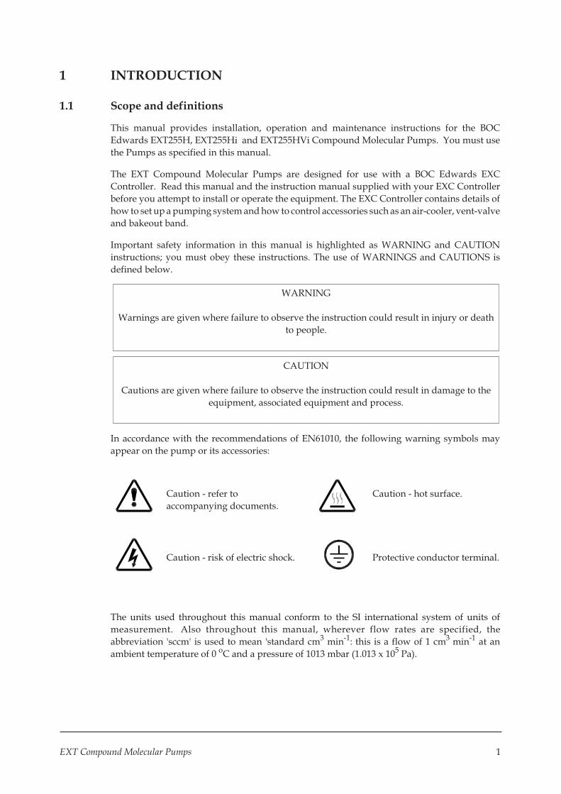
In accordance with the recommendations of EN61010, the following warning symbols may
appear on the pump or its accessories:
Caution - refer to
accompanying documents.
Caution - hot surface.
Caution - risk of electric shock. Protective conductor terminal.
The units used throughout this manual conform to the SI international system of units of
measurement. Also throughout this manual, wherever flow rates are specified, the
abbreviation 'sccm' is used to mean 'standard cm3 min-1: this is a flow of 1 cm3 min-1 at an
ambient temperature of 0 oC and a pressure of 1013 mbar (1.013 x 10⁵ Pa).
EXT Compound Molecular Pumps 1
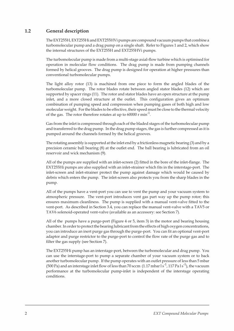
1.2 General description
The EXT255H, EXT255Hi and EXT255HVi pumps are compound vacuum pumps that combine a
turbomolecular pump and a drag pump on a single shaft. Refer to Figures 1 and 2, which show
the internal structures of the EXT255H and EXT255HVi pumps.
The turbomolecular pump is made from a multi-stage axial-flow turbine which is optimised for
operation in molecular flow conditions. The drag pump is made from pumping channels
formed by helical grooves. The drag pump is designed for operation at higher pressures than
conventional turbomolecular pumps.
The light alloy rotor (13) is machined from one piece to form the angled blades of the
turbomolecular pump. The rotor blades rotate between angled stator blades (12) which are
supported by spacer rings (11). The rotor and stator blades have an open structure at the pump
inlet, and a more closed structure at the outlet. This configuration gives an optimum
combination of pumping speed and compression when pumping gases of both high and low
molecular weight. For the blades to be effective, their speed must be close to the thermal velocity
of the gas. The rotor therefore rotates at up to 60000 r min-1.
Gas from the inlet is compressed through each of the bladed stages of the turbomolecular pump
and transferred to the drag pump. In the drag pump stages, the gas is further compressed as it is
pumped around the channels formed by the helical grooves.
The rotating assembly is supported at the inlet end by a frictionless magnetic bearing (3) and by a
precision ceramic ball bearing (8) at the outlet end. The ball bearing is lubricated from an oil
reservoir and wick mechanism (9).
All of the pumps are supplied with an inlet-screen (2) fitted in the bore of the inlet-flange. The
EXT255Hi pumps are also supplied with an inlet-strainer which fits in the interstage-port. The
inlet-screen and inlet-strainer protect the pump against damage which would be caused by
debris which enters the pump. The inlet-screen also protects you from the sharp blades in the
pump.
All of the pumps have a vent-port you can use to vent the pump and your vacuum system to
atmospheric pressure. The vent-port introduces vent gas part way up the pump rotor; this
ensures maximum cleanliness. The pump is supplied with a manual vent-valve fitted to the
vent-port. As described in Section 3.4, you can replace the manual vent-valve with a TAV5 or
TAV6 solenoid-operated vent-valve (available as an accessory: see Section 7).
All of the pumps have a purge-port (Figure 4 or 5, item 3) in the motor and bearing housing
chamber. In order to protect the bearing lubricant from the effects of high oxygen concentrations,
you can introduce an inert purge gas through the purge-port. You can fit an optional vent-port
adaptor and purge restrictor to the purge-port to control the flow rate of the purge gas and to
filter the gas supply (see Section 7).
The EXT255Hi pump has an interstage-port, between the turbomolecular and drag pump. You
can use the interstage-port to pump a separate chamber of your vacuum system or to back
another turbomolecular pump. If the pump operates with an outlet pressure of less than 5 mbar
(500 Pa) and an interstage inlet flow of less than 70 sccm (1.17 mbar l s-1, 117 Pa l s-1), the vacuum
performance at the turbomolecular pump-inlet is independent of the interstage operating
conditions.
2 EXT Compound Molecular Pumps

The EXT255HVi pump also has an interstage-port (14). The interstage-port is located in the
turbomolecular pumping region of the pump and, together with the higher conductance
provided by the larger size interstage-port, enables higher interstage pumping speeds than the
EXT255Hi.
Electrical connection between the EXT and the EXC Controller is by a 19-way connector and a
pump-to-controller cable. The cable is a separate item and is available in a choice of lengths (see
Section 7 for details). If you use an EXC100L controller it is not necessary to buy a separate cable.
The pump may be air-cooled using an optional air-cooler accessory, or water-cooled by passing
water through the water-cooler provided. Two riffled hose connectors are provided for
connection of your cooling-water supply and return pipelines. A thermal sensor monitors the
temperature of the motor and the pump-body.
1.3 Vent options and vent control
To maintain the cleanliness of your vacuum system, we recommend that, whenever you switch
the pump off, you vent the pump (or vacuum system) when the speed of the EXT pump is
between full rotational speed and 50% of full rotational speed. At and above 50% of full
rotational speed, the rotor spins fast enough to suppress any backstreaming of hydrocarbon oil
from your backing pump.
However, if you vent the pump when it is at full rotational speed and the rate of pressure rise is
too high, the pump life may be reduced. We therefore recommend that you either limit the vent
rate (see Section 2.3), or only open the vent-valve after the EXT pump speed has fallen to 50% of
full rotational speed.
The rate of pressure rise cannot be controlled by the manual vent-valve, so if you use the manual
vent-valve, you must only open the vent-valve after the EXT pump speed has fallen to 50% of full
rotational speed.
If you use a TAV5 vent-valve, but you cannot limit the rate of pressure rise, you must only open
the vent-valve after the speed of the EXT pump has fallen to 50% of full rotational speed. If you
use the EXC Controller to control your TAV5 vent-valve, configure the EXC Controller to select
this option: refer to Section 3.4 for more information. The EXC Controller is factory set to vent
when the EXT pump is at 50% of full rotational speed after you select Stop.
EXT Compound Molecular Pumps 3

4 EXT Compound Molecular Pumps
Figure 1 - Cross-section view of EXT255H pump
1. Inlet-flange
2. Inlet-screen
3. Magnetic bearing
4. Safety bearing
5. Envelope
6. Shaft
7. DC motor
8. Ball bearing
9. Oil reservoir
10. Drag stage
11. Spacer ring
12. Stator
13. Rotor

EXT Compound Molecular Pumps 5
Figure 2 - Cross-section view of EXT255HVi pump
1. Inlet-flange
2. Inlet-screen
3. Magnetic bearing
4. Safety bearing
5. Envelope
6. Shaft
7. DC motor
8. Ball bearing
9. Oil reservoir
10. Drag stage
11. Spacer ring
12. Stator
13. Rotor
14. Interstage-port

2 TECHNICAL DATA
2.1 General
Performance See Table 1
Dimensions See Figures 4 and 5
Maximum inlet-flange temperature 100 oC
Maximum magnetic field 3.5 mT Horizontal field
>7mT Vertical field
Installation category EN61010 part 1, Category 1
Pollution degree EN61010 part 1, Category 2
Equipment type Fixed equipment, for indoor use only
2.2 Pumping media
WARNING
Vent dangerous gases and gas mixtures safely. Do not expose people to these gases.
WARNING
Do not use EXT pumps to pump explosive gas mixtures as the pumps are not suitable for
this purpose.
WARNING
On EXT255Hi and EXT255HVi pumps, gas pumped through the interstage-port will mix
with gas pumped through the pump-inlet. Ensure that the gases will not react or combine
to form dangerous gases and substances.
CAUTION
Do not use an EXT to pump gases containing more than 20% oxygen unless the pump is
gas purged. If you do, the lubricant will polymerise and the pump will fail prematurely.
Note that concentrations of gases may be modified by the compression of the pump.
6 EXT Compound Molecular Pumps

2.2.1 Pumps without gas purge
The pumps are designed to pump the following residual gases normally used in high-vacuum
systems :
� Air � Carbon monoxide � Neon � Ethane � Methane
� Nitrogen � Krypton � Argon � Propane
� Carbon dioxide � Helium � Hydrogen � Butane
You can use the pumps to pump oxygen and water vapour, subject to the following conditions :
� Oxygen The oxygen concentration must be less than 20% by volume.
� Water vapour You must ensure that vapour does not condense inside the pump;
refer to Section 3.7.3.
If you wish to pump a gas not in the list above, contact your supplier for advice. If you do not
contact your supplier, you may invalidate the warranty on the pump. The pumps are not
suitable for pumping aggressive or corrosive gases.
2.2.2 Pumps with gas purge
When purged with an inert gas, the pumps can be used to pump oxygen in concentrations above
20% by volume.
2.3 Vent gas specification and vent control data
Although the pump may be vented to atmospheric air, high relative humidity of the air may
greatly increase the subsequent pump-down time. To reduce pump-down times you should
vent the pump with dry, clean gases.
Vent gas Dry air, nitrogen, argon or other
inert gases
Maximum dew point at atmospheric pressure - 22 oC
Maximum size of particulates 1 �m
Maximum concentration of oil 0.1 parts per million
Time for rotational speed to reach 50% >15 sec
Rate of pressure rise see Figure 3
2.4 Purge gas specification
Purge gas Dry nitrogen, argon or other
inert gases
Maximum dew point at atmospheric pressure -22 oC
Maximum size of particulates 1 �m
Maximum concentration of oil 0.1 parts per million
Allowable purge gas flow (when required) 20 to 100 sccm (0.33 to 1.67 mbar l s-1,
33 to 167 Pa l s-1)
Recommended purge gas flow 25 sccm (0.42 mbar l s-1, 42 Pa l s-1)
Maximum allowable purge gas supply pressure 2 bar (gauge) ; 29 psig, 3 x 10⁵ Pa
EXT Compound Molecular Pumps 7
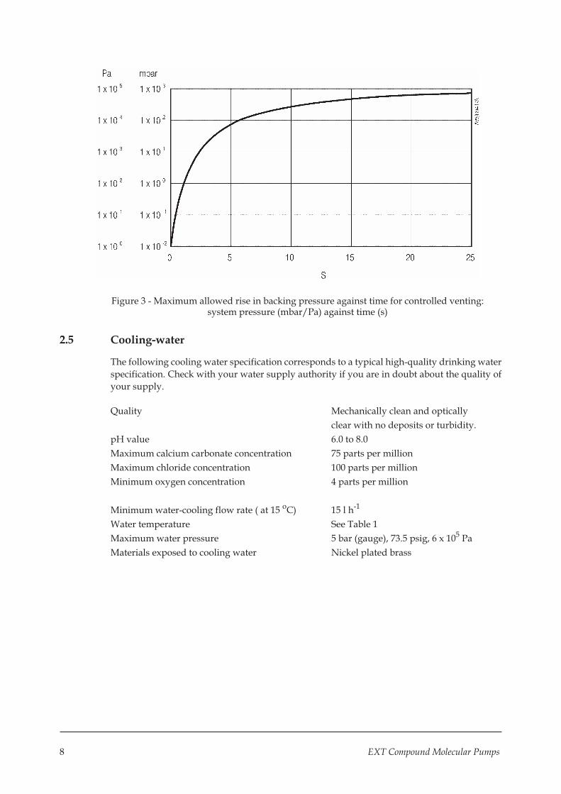
Figure 3 - Maximum allowed rise in backing pressure against time for controlled venting:system pressure (mbar/Pa) against time (s)
2.5 Cooling-water
The following cooling water specification corresponds to a typical high-quality drinking water
specification. Check with your water supply authority if you are in doubt about the quality of
your supply.
Quality Mechanically clean and optically
clear with no deposits or turbidity.
pH value 6.0 to 8.0
Maximum calcium carbonate concentration 75 parts per million
Maximum chloride concentration 100 parts per million
Minimum oxygen concentration 4 parts per million
Minimum water-cooling flow rate ( at 15 oC) 15 l h-1
Water temperature See Table 1
Maximum water pressure 5 bar (gauge), 73.5 psig, 6 x 10⁵ Pa
Materials exposed to cooling water Nickel plated brass
8 EXT Compound Molecular Pumps

Parameter EXT255H EXT255Hi EXT255HVi Notes
Mass
DN100ISO-K inlet flange
DN100CF inlet flange
5.6 kg
8.2 kg
5.6 kg
N/A
6.5 kg
N/A
Inlet-flange DN100ISO-K/DN100CF
DN100ISO-K DN100ISO-K
Outlet-flange DN25NW DN25NW DN25NW
Vent-port
Interstage-port
Purge-flange
1/8 inch BSP
-
DN10NW ▲
1/8 inch BSP
DN25NW
DN10NW ▲
1/8 inch BSP
DN40NW
DN10NW ▲
Inlet pumping speed
N2 # � 220 l s-1 220 l s-1 195 l s-1 Pb < 5 mbar (500 Pa)Qi < 70 sccm(1.17 mbar l s-1)(117 Pa l s-1)
He # � 230 l s-1 230 l s-1 155 l s-1 Pb < 1 mbar (100 Pa)Qi = 0 sccm
H2 # � 180 l s-1 180 l s-1 100 l s-1 Pb < 0.5 mbar (50 Pa)Qi = 0 sccm
Inlet compression ratio
N2 # � > 1 x 10⁸ >1 x 10⁸ 3 x 10⁸ Pb < 5 mbar (500 Pa)
He # � 4 x 10⁵ 2.5 x 10⁵ 2 x 10⁵ Pb < 2 mbar (200 Pa)
H2 # � 1.6 x 10⁴ 1.1 x 10⁴ 5 x 10³ Pb < 1 x 10⁻² mbar (1 Pa)
Interstage pumping speed �
N2 # - 10 l s-1 21 l s-1 Pb = 5 mbar (500 Pa)Qi = 240 sccm (4 mbar l s-1)
(400 Pa l s-1)
Qp = 0 sccm
He #
Ultimate pressure with rotaryvane backing pump *
DN100ISOK inlet flange
DN100CF inlet flange
Ultimate pressure withdiaphragm backing pump �
DN100ISOK inlet flange
DN100CF inlet flange
-
< 5 x 10⁻⁹
< 5 x 10⁻¹⁰
< 5 x 10⁻⁸
< 5 x 10⁻⁸
10 l s-1
< 5 x 10 -9
-
< 5 x 10⁻⁸
-
23 l s-1
< 5 x 10 -9
-
< 5 x 10⁻⁸
-
Pb = 5 mbar (500 Pa)
Qi = 100 sccm
(1.67 mbar l s-1)(167 Pa l s-1)
Qp=<20 sccm
(0.33 mbar l s-1)(33 Pa l s-1)
‡ Pumping speeds are without inlet-screen or inlet-strainer (EXT255Hi/EXT255HVi only). Inlet-screens andinlet-strainers reduce speed by approximately 10%.
# Pb = backing pressure, Qi = flow through the interstage-port (EXT255Hi/EXT255HVi only),Qp = flow through pump-inlet
* Ultimate pressure 48 hours after bakeout with Pb < 1 x 10⁻² mbar (1Pa)† Ultimate pressure 48 hours after bakeout with Pb < 5 mbar (500 Pa)+ Inlet pressure has risen to 1 x 10⁻³ mbar (1 x 10⁻¹ Pa).▲ Not supplied - pump supplied with port blanked
Table 1 - Technical data
EXT Compound Molecular Pumps 9

Parameter EXT255H EXT255Hi EXT255HVi Notes
Maximum backing pressure +
N2
He
H2
12 mbar(1200 Pa)
10 mbar(1000 Pa)
3 mbar(300 Pa)
12 mbar(1200 Pa)
10 mbar(1000 Pa)
3 mbar(300 Pa)
12 mbar(1200 Pa)
10 mbar(1000 Pa)
3 mbar(300 Pa)
Minimum backing pumpdisplacement 0.6 m3 h-1 0.6 m3 h-1 0.6 m3 h-1
Maximum continuous inletpressure §
water-cooling at 15 oC § 2 x 10⁻¹ mbar,20 Pa
2 x 10⁻¹ mbar,20 Pa
2 x 10⁻¹ mbar,20 Pa
air-cooling at 35 oC § 2 x 10⁻² mbar,2 Pa
2 x 10⁻² mbar,2 Pa
2 x 10⁻² mbar,2 Pa
Operating attitude Vertical and upright through to horizontal +2o
Nominal rotational speed 60000 r min-1 60000 r min-1 60000 r min-1
Standby rotational speed 42000 r min-1 42000 r min-1 42000 r min-1
Starting time to 90% speed
EXC100E
EXC120
EXC300
190 sec
130 sec
100 sec
190 sec
130 sec
100 sec
190 sec
130 sec
100 sec
Cooling method Forced-air/water
Forced-air/water
Forced-air/water
Ambient air temperature(forced-air cooling)
Water temperature(water-cooling)
0 - 35 oC
10 - 20 oC
0 - 35 oC
10 - 20 oC
0 - 35 oC
10 - 20 oC
Noise level (at 1 metre) < 50 dB(A) < 50 dB(A) < 50 dB(A)
Recommended controller EXC120 EXC120 EXC120
EXC120 maximum VA input 250 VA 250VA 250VA with bakeout band
Quiescent power 25W 25W 25W
Recommended backing pump † RV3 RV3 RV3§ Above this pressure, rotational speed drops below nominal.+ Inlet pressure has risen to 1 x 10⁻³ mbar (1 x 10⁻¹ Pa).
† A larger backing pump may be required for maximum throughput
Table 1 - Technical data (continued)
2.6 Materials exposed to gases pumped
The following materials and component types are exposed to the gases pumped: aluminium
alloys, stainless steels, fluoroelastomer and nitrile 'O' rings, hydrocarbon lubricant, felt, rare
earth magnets, silicon nitride, phenolic resin and carbon-fibre reinforced epoxy resin.
10 EXT Compound Molecular Pumps

1. Interstage-port (EXT255Hi only) 5. Backing-port
2. Vent-valve 6. Cooling-water connectors
3. Purge-port 7. Allowance for right-angle cable connector
4. Electrical supply connector 8. Earth (ground) bonding point
Figure 4 - EXT255H/EXT255Hi dimensions (mm)
EXT Compound Molecular Pumps 11
EXT255H EXT255Hi

1. Interstage-port 5. Backing-port
2. Vent-valve 6. Cooling-water connectors
3. Purge-port 7. Allowance for right-angle cable connector
4. Electrical supply connector 8. Earth (ground) bonding point
Figure 5 - EXT255HVi dimensions (mm)
12 EXT Compound Molecular Pumps
3 INSTALLATION
WARNING
Safely route all vacuum, vent/purge gas and cooling-water pipelines, and all electrical
cables and wires, so that people cannot trip over them.
3.1 Unpack and inspect
The pump is packed to prevent damage in transit. Take care when you unpack the pump to
avoid excessive shocks which could damage the bearings and reduce the life of the pump. The
pump is supplied with the inlet and outlet sealed to prevent entry of dust and vapour. Do not
remove these seals until you are ready to install the pump on your vacuum system.
Remove all packing materials and check the pump. If the pump is damaged, notify your
supplier and the carrier in writing within three days; state the Item Number of the pump
together with your order number and your supplier's invoice number. Retain all packing
materials for inspection. Do not use the pump if it is damaged.
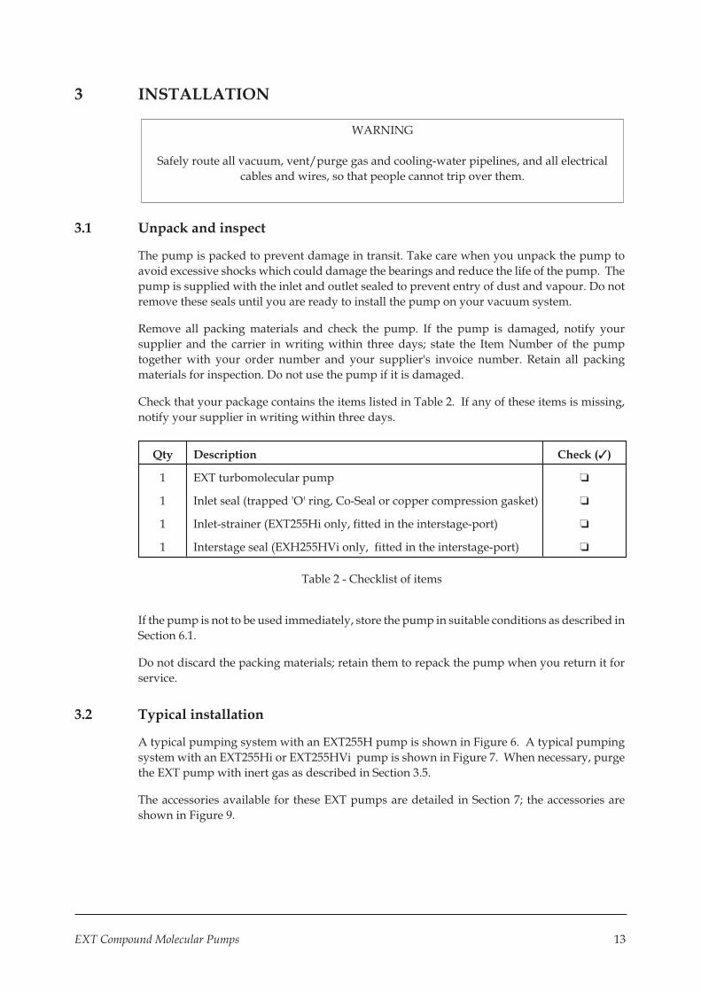
Check that your package contains the items listed in Table 2. If any of these items is missing,
notify your supplier in writing within three days.
Qty Description Check (✓)
1 EXT turbomolecular pump ❏
1 Inlet seal (trapped 'O' ring, Co-Seal or copper compression gasket) ❏
1 Inlet-strainer (EXT255Hi only, fitted in the interstage-port) ❏
1 Interstage seal (EXH255HVi only, fitted in the interstage-port) ❏
Table 2 - Checklist of items
If the pump is not to be used immediately, store the pump in suitable conditions as described in
Section 6.1.
Do not discard the packing materials; retain them to repack the pump when you return it for
service.
3.2 Typical installation
A typical pumping system with an EXT255H pump is shown in Figure 6. A typical pumping
system with an EXT255Hi or EXT255HVi pump is shown in Figure 7. When necessary, purge
the EXT pump with inert gas as described in Section 3.5.
The accessories available for these EXT pumps are detailed in Section 7; the accessories are
shown in Figure 9.
EXT Compound Molecular Pumps 13

1. Vacuum system 7. Vacuum 13. EXC controller
2. High-vacuum gauge 8. Flexible bellows 14. Air-cooler
3. Vibration isolator 9. Foreline trap 15. Vent port adaptor
4. Inlet-screen 10. Rotary backing-pump 16. PRX10 purge restrictor
5. EXT pump 11. Mist filter 17. Regulated purge gas supply
6. Backing valve 12. Cooling-water connectors 18. Vent-valve
19. Alternative position for vent-valve
Figure 6 - Typical pumping system with an EXT255H pump
14 EXT Compound Molecular Pumps

1. Vacuum chamber 1 8. Flexible bellows 16. PRX10 purge restrictor
2. High-vacuum gauge 9. Foreline trap 17. Regulated purge gas supply
3. Vibration isolator 10. Rotary backing-pump 18. Vent-valve
4. Inlet-screen 11. Mist filter 19. Alternative position for vent-valve
5. EXT pump 12. Cooling-water connectors 20. Vacuum chamber 2
6. Not used 13. EXC controller 21. Inlet-strainer
7. Vacuum gauge 14. Air-cooler 22. Interstage-port
15. Vent port adaptor 23. Backing valve
Figure 7 - Typical pumping system with an EXT255Hi/EXT255HVi pump
EXT Compound Molecular Pumps 15
3.3 Connect to the vacuum system
WARNING
Install the pump in the vacuum system before you connect the EXC Controller. This will
ensure that the pump cannot operate and injure people during installation.
3.3.1 Inlet screen
Do not remove the inlet-screen unless you can be sure that there is no danger that debris can fall
into the pump. In order to avoid the danger of injury from the rotor blades, do not remove the
inlet-screen until you are ready to mount the pump onto your system. If the screen is removed,
the pumping speed will increase by approximately 10%.
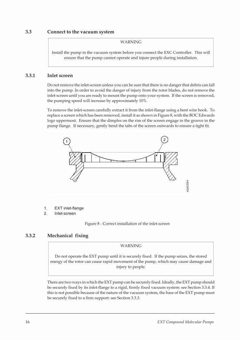
To remove the inlet-screen carefully extract it from the inlet-flange using a bent wire hook. To
replace a screen which has been removed, install it as shown in Figure 8, with the BOC Edwards
logo uppermost. Ensure that the dimples on the rim of the screen engage in the groove in the
pump flange. If necessary, gently bend the tabs of the screen outwards to ensure a tight fit.
1. EXT inlet-flange
2. Inlet-screen
Figure 8 - Correct installation of the inlet-screen
3.3.2 Mechanical fixing
WARNING
Do not operate the EXT pump until it is securely fixed. If the pump seizes, the stored
energy of the rotor can cause rapid movement of the pump, which may cause damage and
injury to people.
There are two ways in which the EXT pump can be securely fixed. Ideally, the EXT pump should
be securely fixed by its inlet-flange to a rigid, firmly fixed vacuum system: see Section 3.3.4. If
this is not possible because of the nature of the vacuum system, the base of the EXT pump must
be securely fixed to a firm support: see Section 3.3.3.
16 EXT Compound Molecular Pumps

3.3.3 Base mounting
Ensure that the base of the pump is securely fixed to a firm support (refer to Figures 4 and 5 for
the fixing hole details). If the pump supports the weight of the vacuum system, the mass of the
vacuum system must be no more than 20 kg.
You must also ensure that your mounting method meets the following requirements, so that the
EXT pump will remain secure in the event of a pump seizure:
� The support mounting must be able to withstand a destructive torque of 620 Nm.
� Fit cap-head fixing screws through the tapped fixing-holes in the base of the pump (seeFigures 4 and 5): use M5 screws.
� The fixing screws must comply with ISO 898-1, with a strength class of 12.9 (nominal tensilestrength 1200 MPa).
� The fixing screw engagement length must be 6 mm or more.
� Tighten the fixing screws to a torque of 12 Nm (1.22 kgf m).
3.3.4 Inlet connection and orientation
The EXT pump can be fixed to the vacuum system by the inlet-flange. The pump can be mounted
in any attitude from vertical and upright through to horizontal ( �2o). If the pump is mounted
horizontally and you use a rotary vane pump to back the EXT pump, the backing port must
point vertically downwards (�20o) to reduce the risk of contamination from the backing pump
oil.
Make sure that the pump-inlet and all components fitted to the pump-inlet are clean and
dust-free. If the pump-inlet is not kept clean, the pump-down time may be increased.
The inlet-connection of the EXT pump is a CF flange or an ISO flange:
� If the pump has a CF flange, use the copper compression gasket supplied with the pump anduse a full complement of bolts to connect the inlet-flange of the pump to the vacuum system.
� If the pump has an ISO flange, use the BOC Edwards trapped ‘O’ ring supplied with thepump and use a minimum of four claw clamps to connect the inlet-flange of the pump to thevacuum system. Ensure that each claw clamp is tightened to a torque of 10 Nm or more.
Alternatively, use a rotatable collar and the trapped ‘O’ ring supplied with the pump toconnect the inlet-flange of the pump to the vacuum system; use a full complement of boltswith the rotatable collar.
Ensure that no torque or other forces are transmitted to the pump from the vacuum system or
the associated pipelines.
If necessary, fit an inlet vibration isolator between the pump-inlet and the vacuum system: refer
to Section 7.4.9 for the Item Numbers, and refer to the instruction manual supplied with the
vibration isolator for installation details. If you fit a vibration isolator, you must securely fix the
base of the EXT pump as described in Section 3.3.3.
Note: The first time you pump down the system to vacuum, you must re-tighten the bolts which secure
the inlet-flange.
EXT Compound Molecular Pumps 17

3.3.5 Backing connection
Use suitable vacuum tubing and connectors to connect the NW flange of the backing-port to
your backing-pump. If necessary, use flexible pipe or bellows to reduce the transmission of
vibration from the backing-pump to the EXT pump.
We recommend that you use a BOC Edwards RV backing-pump. The backing-pump can also be
controlled by the EXC Controller (EXC120 EXC300). The minimum size of the backing-pump
required is given in Table 1. You may have to use a larger backing-pump if you run the pump at a
high inlet pressure or high throughput, or if you purge the pump with more than 25 sccm
(0.42 mbar l s-1, 42 Pa l s-1) of purge gas. The EXT255H is also suitable for use with diaphragm
backing-pumps although the effect of high backing pressure on the pump’s performance and
cooling requirements should be noted (see Table 1 and Section 3.7).
Do not use the EXT pump with a backing pressure below 5 x 10⁻⁴ mbar (5 x 10⁻² Pa). Lower
backing pressures will increase the evaporation rate of the lubricating oil and so will reduce the
life of the bearings.
3.3.6 Interstage connection (EXT255Hi/EXT255HVi only)
The EXT255HVi pump is supplied with an interstage-port seal, and the EXT255Hi pump is
supplied with a combined inlet-strainer/interstage-port seal; leave the inlet-strainer in the
interstage-port, unless you are sure that debris cannot be drawn into the interstage-port.
Use the seal supplied and suitable vacuum tube and connectors to connect the interstage-port to
your vacuum system or to the outlet flange of another turbomolecular pump (if you use the
EXT255Hi or EXT255HVi pump to back another turbomolecular pump).
3.4 Vent-valve connection and control
When you design your system and when you install a vent-valve, take note of the information in
Sections 1.3 and 2.3. You can vent the EXT pump and your vacuum system by any of the
following methods:
� Use the manual vent-valve supplied. Take care not to open the manual vent-valve too
quickly.
� Use a TAV5 or TAV6 solenoid vent-valve accessory (see Section 7) in place of the manual
vent-valve.
� Use a TAV5 or TAV6 solenoid vent-valve connected to a convenient flange on your vacuum
system.
� Use an alternative valve connected to your vacuum system.
If you use the manual vent-valve, you must open the vent-valve only after the EXT pump speed
has fallen to 50% of full rotational speed.
Do not vent from the backing line. If you vent into your vacuum system, select a point upstream
of the pump, to prevent oil backstreaming from the backing line.
If you use the TAV5 or TAV6 vent-valve we recommend that you control it from the EXC
controller.
18 EXT Compound Molecular Pumps

Table 3 gives an indication of the appropriate orifice size to be fitted to the vent valve for given
vacuum system volumes in order that the vent rate is kept within the limits given in Section 2.3.
Vacuum system volume (l) Orifice diameter (mm)
< 20
< 10
< 5
< 2
< 1.0
< 0.7
< 0.5
< 0.35
Table 3 - Vent-restrictor orifice diameter (with atmosphericpressure at the inlet of the vent-valve)
3.5 Purge gas connection
3.5.1 Connect the purge gas
If you want to supply a purge gas to the pump, fit a vent port adaptor (see Section 7.4.7) in place
of the blank plug (Figure 4 or 5, item 3). Connect your gas supply to the purge port.
You must limit the flow rate of the purge gas to the allowed range, also specified in Section 2.4.
To limit the flow rate, use a flow controller or a pressure regulator and calibrated flow restrictor.
The PRX10 purge restrictor accessory (see Section 7.3) is suitable for this purpose. Adjust the
PRX10 as described in the instruction manual supplied with the accessory.
3.5.2 Recommended purge gas flow
The recommended purge gas flow for typical applications is 25 sccm (0.42 mbar l s-1, 42 Pa l s-1).
This flow will protect the pump when you pump oxygen in concentrations above 20% by
volume.
3.6 Electrical installation
Always make the electrical connections to the EXT pump after the pump has been installed on
your vacuum system.
The EXT pump should be electrically bonded to earth (ground) using the connection provided
(Figure 4 or 5, item 8).
The EXC Controller provides the electrical supply to the EXT pump through the multiway
pump-to-controller cable. Connect and lock the bayonet-connectors at the ends of the cable to
the mating connectors on the pump and the EXC Controller.
The EXC Controller is designed to allow a pumping system to be configured in a variety of ways,
from a basic manually-operated system to a fully automatic system with remote control. Refer
to the instruction manual supplied with the EXC Controller to complete the electrical
installation.
EXT Compound Molecular Pumps 19

3.7 Cooling
3.7.1 Introduction
CAUTION
You must cool the pump by forced-air or water-cooling to prevent damage to the bearing
lubricant.
We recommend that wherever possible, you cool the pump by forced-air or water-cooling.
You must use water-cooling in any of the following operating conditions:
� Backing pressure >10 mbar (1000 Pa).
� Backing pressure > 8 mbar (800 Pa) and interstage flow > 30 sccm (0.5 mbar l s-1, 50 Pa l s-1).
� Backing pressure > 5 mbar (500 Pa) and interstage flow > 80 sccm (1.3 mbar l s-1, 130 Pa l s-1).
� Ambient temperature > 35 oC.
� When you use a bakeout band.
In all other operating conditions, you can use forced-air cooling. If you use forced-air to cool the
pump, you must ensure that there is an adequate supply of cooling-air to the pump.
During operation, if the temperature of any surface of the pump is higher than 50 oC, the pump is
too hot and you must increase the cooling.
3.7.2 Forced-air cooling
An air-cooler accessory is available for the EXT pumps (refer to Section 7). Fit the air-cooler as
described in the instruction manual supplied with it. If you wish to use an alternative fan for
air-cooling, ensure that the flow rate is above 70 m3 h-1 (40 cfm)
20 EXT Compound Molecular Pumps
3.7.3 Water-cooling
The cooling-water supply must comply with the specification given in Section 2.5. Pipes in the
water-cooling circuit may become blocked if the cooling-water contains too much calcium
carbonate or if it contains particulates which are too large. Corrosion of the water-cooling circuit
may occur if there is too little calcium carbonate and oxygen in the water. Good quality drinking
water is usually suitable for water-cooling. If in doubt, you must check the quality of your
cooling-water supply and, if necessary, provide treatment and filtration.
Connect the cooling-water supply to the water-cooler on the pump as described below. Either of
the two riffled connectors on the water-cooler can be used for the water supply or return
connections.
1. Push reinforced hose (approximately 6 mm internal diameter) over the ends of the riffled
hose connectors on the water-cooler on the pump.
2. Attach the hose with strong hose clips and make sure that they are tightened securely.
Alternatively, unscrew the riffled hose connectors and remove them from the water-cooler and
make direct connections to the 1/8 BSP female threaded fittings on the water-cooler.
You must turn off the cooling-water supply when you switch off the pump to prevent
condensation of vapours inside the pump. The EXC Controller (EXC120 and EXC300) can
operate a solenoid-valve for this purpose.
If you want to remove the pump for maintenance, and you do not want to break the
cooling-water circuit, unscrew the two M4 cap-head fixing-screws and remove the water-cooler
from the pump. Make sure that there is a layer of thermal contact grease on the water-cooler
before you refit it to the pump.
EXT Compound Molecular Pumps 21

4 OPERATION
WARNING
Do not disconnect the pump-to-controller cable when the EXT pump is operating. If you
do, there may be a risk of injury or death by electric shock.
WARNING
Do not operate the pump unless it is connected to your vacuum system. If you do, the
pump rotor can cause injury. The pump rotor rotates at very high speeds and you may not
be able to see that the pump is rotating.
WARNING
Do not expose any part of your body to vacuum. If you do, you may be injured.
4.1 Start-up
Use the procedure below to start up a basic, manually-controlled pumping system with a
manual vent-valve and an end user version EXC Controller (for example, EXC120 or EXC300).
Refer to the EXC instruction manual where the backing pump and accessories are automatically
controlled by the EXC Controller.
1. Turn the manual vent-valve clockwise to close it.
2. Turn on the cooling-water supply (if water-cooling is used).
3. Start the backing-pump.
4. When the vacuum system pressure is approximately 10 mbar (1 x 10³ Pa) or less, press the
Start/Stop button on the EXC Controller to start the EXT pump.
5. The pump will then accelerate to full operating speed. The pump rotational speed is shown
by the LED speed indicator on the front panel of the EXC Controller.
Note: The first time you pump down the system to vacuum, you must re-tighten the bolts which secure
the inlet-flange: refer to Section 3.3.4.
4.2 Stand-by
You can press the Standby button on the EXC Controller to operate the EXT pump at reduced
rotational speed. Select Standby before or after Start-up, for any of the following reasons:
� To extend pump-bearing life and still maintain adequate vacuum pumping performance
(for example, when you leave a system under vacuum over holiday periods).
� To increase system pressure or to extend the maximum inlet pressure range of the pump
where this suits a particular process.
22 EXT Compound Molecular Pumps
4.3 Shut-down
Note: In an emergency only, open the vent-valve quickly to decelerate the pump rotor in the shortest
possible time.
Use the procedure below to shut down a basic, manually-controlled pumping system with a
manual vent-valve and an end user version EXC Controller (for example, EXC120 or EXC300).
Refer to the EXC Controller instruction manual where the backing-pump and accessories are
automatically controlled by the EXC Controller.
1. Close the valve in the backing-line connecting the EXT pump to the backing-pump.
2. Switch off the backing-pump.
3. Press the Start/Stop button on the EXC Controller to switch off the EXT pump.
4. When the EXT pump rotational speed has fallen to below 50% of full rotational speed, turn
the manual vent-valve anticlockwise to open it. Ensure that the rate of pressure rise does not
exceed the allowed rate of pressure rise, otherwise you can damage the pump: refer to
Sections 1.3 and 2.3.
5. If water-cooling is in use, turn off the cooling-water supply.
4.4 Safety interlocks and control system
The pump protection and safety interlock features are listed below. Refer to the instruction
manual supplied with the EXC Controller for a full description of these features (note that
references to LED’s and buttons do not apply to OEM versions of the EXC controller):
� The EXC Controller monitors the temperature of the EXT pump and the electrical power
consumption of the pump. If the EXC Controller detects excessive power consumption or
temperature, the rotational speed of the pump motor is reduced until the power and
temperature return to normal
� If the rotational speed is reduced to 50% of nominal speed, then the pump is stopped
immediately (or after a user defined time delay) and the Fail LED on the EXC Controller
lights
� If pump rotational overspeed is detected by the EXC Controller, the pump is stopped
immediately and the FAIL LED on the EXC Controller lights.
If the Fail LED lights, switch off the backing-pump immediately and vent the EXT pump. Once
the EXT pump has stopped, rectify the cause of the failure (refer to Section 5.5), press the EXC
Controller Start/Stop button to reset the Fail condition, and restart the EXT pump. If the pump
is hot, allow sufficient time for it to cool before you restart it.
EXT Compound Molecular Pumps 23

4.5 Bakeout
CAUTION
When you bake the EXT pump to above 70 oC at the inlet-flange, you must cool the pump
by water-cooling, to prevent damage to the bearing lubricant.
If you heat your EXT pump (and your vacuum system), you will speed up the degassing process
so that the pump will reach ultimate vacuum in the shortest possible time. If you heat the pump,
this will also prevent condensation of vapours inside the pump.
You can use the BOC Edwards BX bakeout band to heat the pump (refer to Section 7). Fit the
band around the pump, just below the inlet-flange. When you bake the pump or the system,
make sure that the temperature of the inlet-flange does not exceed 100 oC.
If you bake your vacuum system and the temperature of the system exceeds 200 oC, you must
put a radiation shield between the system and the EXT pump. This radiation shield will reduce
the heat radiated onto the pump rotor.
Typically, a bakeout of four hours is long enough to remove water condensation from the pump.
However, the bakeout time will depend on the amount of condensation in the pump and the
vacuum system, and the ultimate pressure you want to achieve.
24 EXT Compound Molecular Pumps
5 MAINTENANCE
WARNING
Allow the pump-rotor to stop, then disconnect the EXC Controller before you remove the
pump from your vacuum system for maintenance or fault-finding procedures.
5.1 Introduction
The maintenance operations for the EXT Turbomolecular pumps are described in the following
sections. The ISX inlet-screen, the WCX water-cooler, the inlet-strainer, interstage-port seal and
inlet-flange seals are available as spares (refer to Section 7). Fit the ISX inlet-screen as described
in Section 3.3.1. Fit the WCX water-cooler as described in Section 3.7.2.
5.2 Bearing life
When supplied, the pump contains sufficient lubricant to supply the bearings for life. No
routine maintenance is therefore required between bearing replacements. The bearings are not
user-serviceable. The bearings will need to be replaced when they reach the end of their service
life. This is typically more than 20,000 hours, but may be less; this depends on the type of
pumping duty on which the pump is used.
When the bearings need replacement, we recommend that you exchange your pump for a
factory reconditioned replacement. Alternatively, you can send your pump to a BOC Edwards
Service Centre to have the bearings replaced.
When you return EXT pumps to BOC Edwards Service Centres please use the procedure
included at the end of this manual. However, the instruction to drain all fluids does not apply to
the lubricant in the EXT pump oil-reservoirs.
5.3 Rotor life
The life of the EXT pump rotor is typically 40,000 to 50,000 cycles (of acceleration to full speed,
and then deceleration to a stop). The pump rotor is not user-serviceable.
We therefore recommend that you exchange your pump for a factory reconditioned
replacement every 20,000 cycles, or 10 years of use, whichever occurs first. Alternatively, you
can send your pump to a BOC Edwards Service Centre for a major service (which will include
rotor replacement).
When you return EXT pumps to BOC Edwards Service Centres please obey the procedure
included at the end of this manual. However, the instruction to drain all fluids does not apply to
the lubricant in the EXT pump oil-reservoirs.
EXT Compound Molecular Pumps 25

5.4 Clean the pump
WARNING
Clean the external surfaces of the EXT pump in a well-ventilated location. When you use
cleaning solutions and solvents to clean the pump, observe all precautions specified by the
manufacturer. Avoid inhalation of any particulates which may be present in the pump.
CAUTION
Do not attempt to clean any parts of the EXT pump other than the external surfaces.
Organic solvents may damage internal pump components. Do not use abrasive materials
to clean any part of the pump.
If the inside of the EXT pump is contaminated, it may not be possible to achieve the specified
ultimate vacuum, or pump-down time may increase. In these circumstances, you should return
the pump to a BOC Edwards Service Centre, where the pump will be dismantled and cleaned.
Use the procedure given in the forms at the end of this manual to return the pump.
You can use any organic solvent to clean the external surfaces of the EXT pump. We recommend
that you use non-CFC solvents, such as isopropanol or ethanol. Use a cleaning solution which is
suitable for the contaminants on the pump surfaces.
For environmental reasons, keep wastage of cleaning solutions and solvents to a minimum.
5.5 Fault finding
Refer to Table 4 for the possible causes of faults and for the recommended actions to rectify
faults. Table 4 is applicable to a basic, manually controlled pumping system with an EXC
Controller configured for local (manual) operation.
Note that if you use an EXDC Pump Drive Module to control the EXT pump, or if you use an EXC
Controller configured for remote operation to control the EXT pump, some of the checks and
actions in Table 4 may not apply to your system.
Refer to the fault finding section of the instruction manual supplied with your EXDC Pump
Drive Module or EXC Controller for further fault finding information.
26 EXT Compound Molecular Pumps

Symptom Check Action
The pump does not
rotate. After pressing
start - Fail LED not lit.
Is the EXC Controller power
LED lit?
If not, check that the electrical
supply is on, check that the switch
at the rear of the EXC Controller is
on, check the fuse in the rear of
the EXC Controller.
If all of the above are OK then the
EXC Controller is faulty. Consult
BOC Edwards or your supplier
Is the EXC Controller
Start/Stop LED flashing?
If so, check that the correct links
are made on the EXC Controller
logic interface (refer to the
instruction manual supplied with
the EXC Controller).
Check that any system interlocks
are correctly made (refer to the
instruction manual supplied with
the EXC Controller).
Check that the pump-to-controller
cable is connected.
If you have made all of the above
checks and cannot identify the
cause of the fault, consult BOC
Edwards or your supplier.
Is the EXC Controller first
speed indication LED lit?
If not, the EXC Controller is
faulty. If lit, then the EXT pump
is faulty. Consult BOC Edwards
or your supplier.
The EXC Controller
trips into Fail - at any
speed.
Are the system interlocks
correctly connected?
Ensure that the system interlocks
do not open after the EXT pump
has started.
Table 4 - Fault finding
EXT Compound Molecular Pumps 27

Symptom Check Action
The EXC Controller
trips into Fail during
the ramp-up and before
50% speed is reached.
Is the inlet pressure too high?
Is the backing pressure too
high?
Is the EXT pump running too
hot?
If so, reduce the pumping load, or
check for a gross leak into the
system.
Increase the cooling-water flow or
decrease the water temperature or
do both. You may need to change
from air-cooling to water-cooling.
(Refer to Section 2 for maximum
inlet pressure and cooling
requirements). Check that
external heat sources (such as
system bakeout heaters) are not
excessive.
Does the rotor rotate freely? If not, the EXT pump-bearings are
damaged. Consult BOC Edwards
or your supplier.
Is the timer set incorrectly? Increase the timer setting (refer to
the instruction manual supplied
with the EXC Controller). If the
EXC Controller still trips into Fail
consult BOC Edwards or your
supplier.
The EXC Controller
trips into Fail after 50%
speed has been reached
- the first two speed
LEDs are lit.
Is the pressure too high? If so, reduce the pumping load or
check for a gross leak into the
system.
If the high gas load is temporary,
configure the EXC Controller to
delay the Fail trip on 50% speed
and set an appropriate delay time
(refer to the instruction manual
supplied with the EXC
Controller).
Is the EXT pump running too
hot?
Increase the cooling-water flow or
decrease the water temperature or
do both. You may need to change
from air-cooling to water-cooling.
Does the EXT pump rotor
rotate freely?
If not, the EXT pump-bearings are
damaged. Consult BOC Edwards
or your supplier.
Table 4 - Fault finding (continued)
28 EXT Compound Molecular Pumps

Symptom Check Action
The EXC Controller
trips into Fail - all the
speed LEDs are lit.
- Consult BOC Edwards or your
supplier.
Ultimate pressure
cannot be reached.
Is the pressure limited by
water vapour ?
Bake the system and pump.
Are any of the vacuum gauges
contaminated ?
If so, clean or replace them.
Is the pumping speed
insufficient (due to poor
conductance between the
pump and the gauge or too
large a chamber) ?
Increase the conductance or
reduce the volume.
Is the interstage inlet pressure
> 0.2 mbar (20 Pa) ?
If the interstage inlet pressure is
too high, inlet pressure at the
turbomolecular inlet is reduced;
ensure that the interstage inlet
pressure is < 0.2 mbar (20 Pa).
Is the backing pressure <
12 mbar (1200 Pa)?
Check for backing line leaks. If the
backing pressure is too high, you
may need a larger backing-pump.
Is the high-vacuum area of the
system contaminated ?
If so, clean the high-vacuum
system.
Check the rest of your system
for leaks and contamination.
If found, clean the contaminated
areas and repair the leaks.
Remove the pump from the
system and test the ultimate
pressure of the pump alone
(see Section 2 for
specification).
If poor, check the pump for
contamination and if necessary
return the pump as described in
Section 5.4. Leak-check the pump.
If the leak rate > 1 x 10⁻⁷ mbar l s-1
(1 x 10⁻⁵ Pa l s-1), consult BOC
Edwards or your supplier.
Table 4 - Fault finding (continued)
EXT Compound Molecular Pumps 29
Symptom Check Action
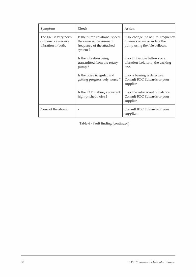
The EXT is very noisy
or there is excessive
vibration or both.
Is the pump rotational speed
the same as the resonant
frequency of the attached
system ?
If so, change the natural frequency
of your system or isolate the
pump using flexible bellows.
Is the vibration being
transmitted from the rotary
pump ?
If so, fit flexible bellows or a
vibration isolator in the backing
line.
Is the noise irregular and
getting progressively worse ?
If so, a bearing is defective.
Consult BOC Edwards or your
supplier.
Is the EXT making a constant
high-pitched noise ?
If so, the rotor is out of balance.
Consult BOC Edwards or your
supplier.
None of the above. - Consult BOC Edwards or your
supplier.
Table 4 - Fault finding (continued)
30 EXT Compound Molecular Pumps

6 STORAGE AND DISPOSAL
6.1 Storage
Use the following procedure to store the pump.
1. Place protective covers over the inlet, outlet, interstage (EXT255Hi/EXT255HVi only),
purge and vent ports.
2. Place the pump in its packing materials. For fastest pump-down when the pump is put back
into service, seal the pump inside a plastic bag together with a suitable desiccant.
3. Store the pump in cool, dry conditions until required for use. When required, prepare and
install the pump as described in Section 3.
4. Keep the pump upright at all times to prevent the drainage of oil from the bearing reservoir.
5. Avoid long-term storage if possible. When long-term storage is necessary, the pump should
be set up and run for at least eight hours every six months.
6.2 Disposal
WARNING
In the unlikely event that the rotor fails, dust may be generated from the carbon fibre
reinforced components in the pump. If the rotor has failed:
� Wear the appropriate personal protective equipment (gloves, a dust-proof mask
which covers the nose and mouth, an apron or overalls, and safety glasses or
goggles) when you handle the pump.
� Ensure that the pump inlet, outlet, and vent-, interstage- and purge-ports are all
blanked off/sealed before you dispose of the EXT pump.
Dispose of the EXT Turbomolecular Pump and any components and accessories safely in
accordance with all local and national safety and environmental requirements.
Take particular care with any components which have been contaminated with dangerous
process substances.
Take appropriate action to avoid inhalation of any particulates which may be present in the
pump.
Do not incinerate the pump. The pump contains phenolic and fluorosilicone materials which
can decompose to very dangerous substances when heated to high temperatures.
EXT Compound Molecular Pumps 31

7 SERVICE, SPARES AND ACCESSORIES
7.1 Introduction
BOC Edwards products, spares and accessories are available from BOC Edwards companies in
Belgium, Brazil, China, France, Germany, Israel, Italy, Japan, Korea, Singapore, United
Kingdom, USA and a world-wide network of distributors. The majority of these employ service
engineers who have undergone comprehensive BOC Edwards training courses.
Order spare parts and accessories from your nearest BOC Edwards company or distributor.
When you order, please state for each part required:
� Model and Item Number of your equipment
� Serial number (if any)
� Item Number and description of the part
7.2 Service
BOC Edwards products are supported by a world-wide network of BOC Edwards Service
Centres. Each Service Centre offers a wide range of options including: equipment
decontamination; service exchange; repair; rebuild and testing to factory specifications.
Equipment which has been serviced, repaired or rebuilt is returned with a full warranty.
Your local Service Centre can also provide BOC Edwards engineers to support on-site
maintenance, service or repair of your equipment.
For more information about service options, contact your nearest Service Centre or other BOC
Edwards company.
7.3 Spares
7.3.1 ISX inlet-screen
An inlet-screen is fitted to your pump as supplied to prevent damage from the entry of debris
into the pump. The Item Numbers of replacement inlet-screens are given below. Select the
inlet-screen according to the pump inlet-flange size.
Flange size Inlet-screen Item Number
DN100ISO-K/DN100CF ISX100 B580-51-001
7.3.2 Inlet-strainer (EXT255Hi pump only)
The EXT255Hi pump is supplied with an inlet-strainer for the interstage-port. The Item Number
of a replacement inlet-strainer is given below.
Interstage-port size Item Number
DN25NW A223-06-067
32 EXT Compound Molecular Pumps

7.3.3 Interstage-port seal (EXT255HVi pump only)
The EXT255HVi pump is supplied with a fluoroelastomer 'O' ring seal for the interstage-port.
The Item Number of a replacement interstage-port seal is given below.
Interstage-port size Item Number
DN40NW C105-16-395
7.3.4 WCX water-cooler
A water-cooler is fitted to your pump as supplied. The Item Number of a replacement
water-cooler is given below.
Water-cooler Item Number
WCX500 B580-61-001
7.3.5 Inlet-flange seals
EXT pumps are supplied with an inlet seal. The Item Numbers of replacement seals are given
below.
Inlet-flange Inlet seal Item Number
DN100ISO-K ISO100 trapped 'O' ring, fluoroelastomer B271-58-171
DN100CF Copper compression gasket (pack of 5) C082-00-008
7.4 Accessories
7.4.1 Installation
The accessories available for use with the EXT turbomolecular pumps are described in the
following Sections. Figure 9 shows how the accessories are fitted to an EXT pump.
7.4.2 EXC Controller
The BOC Edwards EXC Controllers provide the facilities necessary for operating a pumping
system based on an EXT255H, EXT255Hi or EXT255HVi pump. The Item Numbers of the EXC
Controllers are given below.
Controller Voltage Item Number
EXC100E 90 - 264 V a.c. D396-20-000
EXC100L 90 - 264 V a.c. D396-22-000
EXC120 90 - 264 V a.c. D396-16-000
EXC300 90 - 132/180 - 264 V a.c. D396-14-000
EXT Compound Molecular Pumps 33

7.4.3 Pump-to-controller cable
You must fit a pump-to-controller cable between an EXC Controller and the EXT pump. A cable
is not supplied with the EXT Pump or the EXC Controller (except EXC100L). The following
cables are available:
Cable Length Item Number
Pump-to-controller 1 m D396-18-010
Pump-to-controller 3 m D396-18-030
Pump-to-controller 5 m D396-18-050
7.4.4 EXDC Drive Modules
Fit an EXDC Drive Module as an alternative to an EXC Controller and pump-to-controller cable.
Drive Module Item Number
EXDC80 D396-40-000
EXDC160 D396-41-000
7.4.5 BX bakeout band
A BX bakeout band accelerates the degassing of the pump to enable it to achieve lower pressures.
It may also be used to protect the pump from condensation of contaminants. The bakeout bands
are available in 110-120 V or 220-240 V versions and may be powered from a rear panel socket on
the EXC Controller.
Pump Bakeout band Item Number
EXT255H/Hi BX250 (110 V) B580-52-041
BX250 (240 V) B580-52-061
7.4.6 FL20K foreline trap
The foreline trap minimises oil vapour backstreaming from the backing pump and is
recommended where the highest system cleanliness is required.
Foreline trap Item Number
FL20K A133-05-000
34 EXT Compound Molecular Pumps

1. Vibration isolator 6. VRX vent-restrictor 11. Vent port adaptor
2. Bakeout band 7. Solenoid vent-valve 12. Purge restrictor
3. Inlet-flange seal 8. DN10NW adaptor 13. Air-cooler
(supplied) 9. Manual vent-valve (supplied) 14. Inlet strainer (supplied)*
4. EXT255Hi pump 10. Water-cooler (on opposite 15. Interstage-port ✝
5. Vent-port side of the pump) 16. Bakeout band position
17. Inlet-screen (supplied)
* EXT255Hi only
✝ EXT255Hi/EXT255HVi only
Figure 9 - Installation of optional accessories (and spares): EXT255Hi shown
EXT Compound Molecular Pumps 35

7.4.7 TAV vent-valve and vent-port adaptor
Two solenoid-operated vent-valves are available for system venting. The valves are 24 V d.c.,
normally-open, and can be driven automatically from the EXC Controller. The solenoid-valve is
fitted in place of the manual-valve, or alternatively can be fitted with an adaptor (supplied with
the valve) and be used with any suitable NW10 flanged port on your vacuum system.
The vent-port adaptor allows the vent-port or the purge-port to be used with any suitable NW10
fitting: see Figure 9, item 8 and item 11.
Product Item Number
TAV5 vent-valve B580-66-010
TAV6 vent-valve B580-66-020
NW10-1/8 inch BSP male adaptor B580-66-011
7.4.8 ACX air-cooler
An ACX air-cooler can be fitted to the EXT pump. However, please refer to Section 3 to check the
suitability of air-cooling in a particular application.
Pump Air-cooler Item Number
EXT255H/Hi ACX250H B580-53-160
7.4.9 Vibration isolators
In applications where the small amount of vibration generated by the turbomolecular pump is a
problem, a vibration isolator can be fitted. The isolator consists of two special flanges separated
by a flexible bellows and a rubber, anti-vibration, outer collar. The isolator required depends on
the pump inlet-flange size.
Inlet-flange size Item Number
DN100ISO-K B580-20-000
7.4.10 PRX purge-restrictor
A modified DN10NW centring-ring is available to filter the purge gas and restrict its flow rate to
the recommended flow of 25 sccm. The restrictor is suitable for all EXT pumps fitted with a
purge-port.
Purge-restrictor Flange size Item Number
PRX10 NW10 B580-65-001
36 EXT Compound Molecular Pumps

7.4.11 VRX vent-restrictor
Use a VRX fixed orifice vent-restrictor to restrict the flow of vent gas into the EXT pump. Refer to
Section 3.4 for information on the selection of the correct VRX vent-restrictor.
Vent-restrictor Orifice diameter (mm) Item Number
VRX10 0.1 B580-66-021
VRX20 0.2 B580-66-022
VRX30 0.3 B580-66-023
VRX50 0.5 B580-66-024
VRX70 0.7 B580-66-025
EXT Compound Molecular Pumps 37

This page intentionally blank.
38 EXT Compound Molecular Pumps

Return of BOC Edwards Equipment - Procedure
Form HS1
INTRODUCTIONBefore returning your equipment, you must warn BOC Edwards if substances you used (and produced)in the equipment can be hazardous. This information is fundamental to the safety of our Service Centreemployees and will determine the procedures employed to service your equipment.Complete the Declaration (HS2) and send it to BOC Edwards before you dispatch theequipment. It is important to note that this declaration is for BOC Edwards internal use only, andhas no relationship to local, national or international transportation safety or environmentalrequirements. As the person offering the equipment for shipment, it is your responsibility to ensurecompliance with applicable laws.
GUIDELINES• Equipment is 'uncontaminated' if it has not been used, or if it has only been used with substances
that are not hazardous. Your equipment is 'contaminated' if it has been used with any substancesclassified as hazardous under EU Directive 67/548/EEC (as amended) or OSHA Occupational Safety(29 CFR 1910).
• If your equipment has been used with radioactive substances, biological or infectious agents,mercury, polychlorinated biphenyls (PCB’s), dioxins or sodium azide, you must decontaminate itbefore you return it to BOC Edwards. You must send independent proof of decontamination (forexample a certificate of analysis) to BOC Edwards with the Declaration (HS2). Phone BOCEdwards for advice.
• If your equipment is contaminated, you must either:• Remove all traces of contamination (to the satisfaction of laws governing the transportation of
dangerous/hazardous substances).• Or, properly classify the hazard, mark, manifest and ship the equipment in accordance with
applicable laws governing the shipment of hazardous materials.Note: Some contaminated equipment may not be suitable for airfreight.
PROCEDURE1. Contact BOC Edwards and obtain a Return Authorisation Number for your equipment.2. Complete the Return of BOC Edwards Equipment - Declaration (HS2).3. If the equipment is contaminated, you must contact your transporter to ensure that you properly
classify the hazard, mark, manifest and ship the equipment, in accordance with applicable lawsgoverning the shipment of contaminated/hazardous materials. As the person offering the equipmentfor shipment, it is your responsibility to ensure compliance with applicable law. Note: Equipmentcontaminated with some hazardous materials, such as semiconductor by-products,may not be suitable for airfreight - contact your transporter for advice.
4. Remove all traces of hazardous gases: pass an inert gas through the equipment and any accessoriesthat will be returned to BOC Edwards. Where possible, drain all fluids and lubricants from theequipment and its accessories.
5. Seal up all of the equipment's inlets and outlets (including those where accessories were attached)with blanking flanges or, for uncontaminated product, with heavy gauge tape.
6. Seal equipment in a thick polythene/polyethylene bag or sheet.7. If the equipment is large, strap the equipment and its accessories to a wooden pallet. If the
equipment is too small to be strapped to a pallet, pack it in a suitable strong box.8. Fax or post a copy of the Declaration (HS2) to BOC Edwards. The Declaration must arrive before
the equipment.9. Give a copy of the Declaration (HS2) to the transporter. You must tell your transporter if the
equipment is contaminated.10. Seal the original Declaration in a suitable envelope: attach the envelope securely to the outside of
the equipment package, in a clear weatherproof bag.WRITE YOUR RETURN AUTHORISATION NUMBER CLEARLY ON THEOUTSIDE OF THE ENVELOPE OR ON THE OUTSIDE OF THE EQUIPMENTPACKAGE.P
900-
70-0
00 Is
sue
K

Return of BOC Edwards Equipment - Declaration
Form HS2
You must:
• Know about all of the substances which have been used and produced in the equipment before you complete this Declaration
• Read the Return of BOC Edwards Equipment - Procedure (HS1) before you complete this Declaration
• Contact BOC Edwards to obtain a Return Authorisation Number and to obtain advice if you have any questions
• Send this form to BOC Edwards before you return your equipment
Return Authorisation Number:
Equipment/System Name_________________________
Part Number _________________________________
Serial Number_________________________________
Has the equipment been used, tested or operated ?
YES R Go to Section 2 NO R Go to Section 4
IF APPLICABLE:
Tool Reference Number_________________
Process ______________________________
Failure Date___________________________
Serial Number ofReplacement Equipment_________________
Are any substances used or produced in the equipment:
• Radioactive, biological or infectious agents, mercury, poly chlorinated biphenyls (PCBs), dioxins or sodium azide? (if YES, see Note 1) YES R NO R
• Hazardous to humanhealth and safety? YES R NO R
Note 1 : BOC Edwards will not accept delivery of any equipment that is contaminated with radioactive substances, biological/infectious agents, mercury, PCB’s, dioxins or sodium azide, unless you:
• Decontaminate the equipment• Provide proof of decontamination
YOU MUST CONTACT BOC EDWARDS FOR ADVICE BEFORE YOU RETURN SUCH EQUIPMENT
Print your name:_________________________________Print your job title:_________________________
Print your organisation:____________________________________________________________________
Print your address:_______________________________________________________________________
_______________________________________________________________________Telephone number: ___________________________Date of equipment delivery: ______________
I have made reasonable enquiry and I have supplied accurate information in thisDeclaration. I have not withheld any information, and I have followed the Return ofBOC Edwards Equipment - Procedure (HS1).
Signed: _____________________________________Date______________
• who did you buy the equipment from ? _____________________________
• give the supplier’s invoice number_________________________________If you have a warranty claim:
Substance name ChemicalSymbol
Precautions required (for example,use protective gloves, etc.)
Action required after a spill,leak or exposure
Note: Please print out this form, sign it and return the signed form as hard copy.
SECTION 1: EQUIPMENT
SECTION 2: SUBSTANCES IN CONTACT WITH THE EQUIPMENT
SECTION 3: LIST OF SUBSTANCES IN CONTACT WITH THE EQUIPMENT
SECTION 4: RETURN INFORMATION
SECTION 5: DECLARATION
P90
0-71
-000
Issu
e K
Reason for return and symptoms of malfunction _________________________________________________
_________________________________________________________________________________

This page intentionally blank.

UNITED KINGDOM
CORPORATE HEADQUARTERSBOC EDWARDS Manor RoyalCrawleyWest Sussex RH10 9LWTel +(44) 1293 528844Fax +(44) 1293 533453
BOC EDWARDSWingates Industrial EstateGreat Bank RoadWesthoughton, BoltonLancashireBL5 3SLTel +(44) 1942 652652Fax +(44) 1942 652651
AMERICA (USA)
USA HEADQUARTERSBOC EDWARDSOne Edwards Park301 Ballardvale StreetWilmington, MA 01887Tel +(1) 978 658 5410Toll free (USA only) 1 800 848 9800Fax +(1) 978 658 7969
3901 Burton DriveSanta Clara, CA 95054Tel +(1) 408 496 1177Fax +(1) 408 496 1188
1810 West Drake DriveSuite 101Tempe, AZ 85283Tel +(1) 602 777 7007Fax +(1) 602 777 2244
11701 Stonehollow DriveSuite 100Austin, TX 78758Tel +(1) 512 491 6622Fax +(1) 512 491 0629
3501 Island AvenuePhiladelphia, PA 19153Tel +(1) 215 365 8653Fax +(1) 978 753 6846
BELGIUM
BOC EDWARDSBergensesteenweg 709B1600 Sint-Pieters-LeeuwBrusselsTel +(32) 2 363 0030Fax +(32) 2 363 0064
BRAZIL
BOC DO BRASIL LTDADIVISÃO EDWARDS ALTO VACORua Bernado Wrona 22202710 São Paulo-SPTel +(55) 11 3952 5000Fax +(55) 11 3965 2766
CANADA
BOC EDWARDS5975 Falbourne StreetMississauga, Ontario L5R3W6CanadaTel +(1) 905 501 2558Fax +(1) 905 501 1632
12055 Cote de LiesseDorval, Quebec H9P1B4CanadaTel +(1) 514 631 3501Fax +(1) 514 631 3502
CHINA
BOC TRADING (SHANGHAI) CO. LTD.23 Fu Te Road (N)Wai Gao Qiao Free Trade ZonePudongShanghai, 200131PRC ChinaTel +(86 21) 5866 9618Fax +(86 21) 5866 9993
FRANCE
BOC EDWARDS125 Avenue Louis Roche92238 Gennevilliers, CedexParisTel +(33) 1 47 98 24 01Fax +(33) 1 47 98 44 54
GERMANY
BOC EDWARDSAmmerthalstraße 3685551 KirchheimMunichTel +(49) 89 99 19 18 0Fax +(49) 89 99 19 18 99
HONG KONG S.A.R.
BOC EDWARDS (ASIA)12 Chun Yat StreetTseung Kwan O Industrial EstateTseung Kwan O, KowloonHong Kong S.A.R.Tel +(852) 2372 2640Fax +(852) 2796 9095
INDIA
BOC EDWARDSDIVIN. OF BOC INDIA LIMITED203 Surya Kiran Building19 Kasturba Gandhi MargNew Delhi - 110 001IndiaTel +(91) 11 851 0065Fax +(91) 11 851 0245
ISRAEL
EDWARDS ISRAEL VACUUM LTD.5 Habarzel BlvdGat 2000 Industrial ZoneQiryat Gat 82000Tel +(972) 8 681 0633Fax +(972) 8 681 0640
ITALY
BOC EDWARDSVia Carpaccio 3520090 Trezzano sul NaviglioMilanTel +(39) 02 48 4471Fax +(39) 02 48 401638
JAPAN
HEADQUARTERSBOC EDWARDSShuwa Shiba Park Building A-3F2-4-1 Shibakoen Minato-kuTokyo, 105-0011Tel +(81) (0) 3 5470 6530Fax +(81) (0) 3 5470 6521
KOREA
HEADQUARTERSSONGWON EDWARDS LTD.5th FL. Daewoo Engineering Bldg.Soonae-dongBundang-gu, Sungnam CityKyungki-do, KoreaTel +(82) 31 716 7070Fax +(82) 31 738 1001-3
FACTORY & GVSONGWON EDWARDS LTD.625-7 Upsong-dongChunan CityChungchong Nam-doKoreaTel +(82) 41 621 7070Fax +(82) 41 621 7700
SINGAPORE
BOC EDWARDS (ASIA)42 Loyang DriveLoyang Industrial EstateSingapore 508962Tel +(65) 6546 8408Fax +(65) 6546 8407
TAIWAN, R.O.C.
EDWARDS TECHNOLOGIES LIMITEDNo. 434 Chung hua RoadToufen Town, Miaoli CountyTaiwan ROCTel +(886) 37 611422Fax +(886) 37 611401
http://[email protected]
PLEASE CONTACT ANY OF THESE COMPANIES FOR DETAILS OF OTHER SALES AND SERVICE CENTRES IN YOUR AREA.BOC Edwards is part of BOC Limited. BOC Edwards and the stripe symbol are trade marks of The BOC Group.© BOC Edwards 2003
Produced by Technical Publicity [email protected]
P80
0-80
-000
Issu
e J
01A
09-0
10