ba 198/00/en/11.99 field communication profibus · pdf fileguidelines for planning and...
TRANSCRIPT

Field CommunicationPROFIBUS-DP/PA:Guidelines forplanning andcommissioning
PROFIBUS-PA
PROFIBUS-DP
BA 198/00/en/11.99Version 1.052003876
Hauser+EndressThe Power of Know How

Endress+Hauser
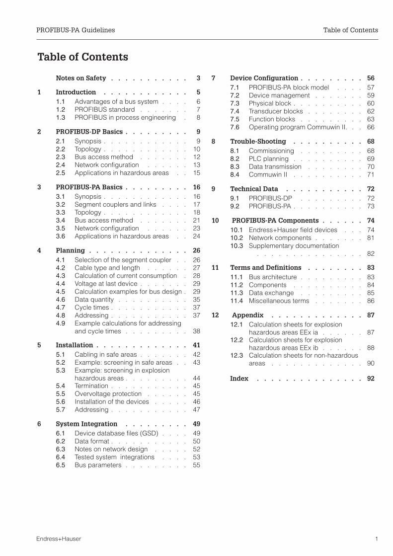
Table of Contents
Notes on Safety . . . . . . . . . . . 3
1 Introduction . . . . . . . . . . . . 51.1 Advantages of a bus system . . . . 61.2 PROFIBUS standard . . . . . . . 71.3 PROFIBUS in process engineering . 8
2 PROFIBUS-DP Basics . . . . . . . . . 92.1 Synopsis . . . . . . . . . . . . 92.2 Topology . . . . . . . . . . . . 102.3 Bus access method . . . . . . . 122.4 Network configuration . . . . . . 132.5 Applications in hazardous areas . . 15
3 PROFIBUS-PA Basics . . . . . . . . . 163.1 Synopsis . . . . . . . . . . . . 163.2 Segment couplers and links . . . . 173.3 Topology . . . . . . . . . . . . 183.4 Bus access method . . . . . . . 213.5 Network configuration . . . . . . 233.6 Applications in hazardous areas . . 24
4 Planning . . . . . . . . . . . . . . 264.1 Selection of the segment coupler . . 264.2 Cable type and length . . . . . . 274.3 Calculation of current consumption . 284.4 Voltage at last device . . . . . . . 294.5 Calculation examples for bus design . 294.6 Data quantity . . . . . . . . . . 354.7 Cycle times . . . . . . . . . . . 374.8 Addressing . . . . . . . . . . . 374.9 Example calculations for addressing
and cycle times . . . . . . . . . 38
5 Installation . . . . . . . . . . . . . 415.1 Cabling in safe areas . . . . . . . 425.2 Example: screening in safe areas . . 435.3 Example: screening in explosion
hazardous areas . . . . . . . . . 445.4 Termination . . . . . . . . . . . 455.5 Overvoltage protection . . . . . . 455.6 Installation of the devices . . . . . 465.7 Addressing . . . . . . . . . . . 47
6 System Integration . . . . . . . . . 496.1 Device database files (GSD) . . . . 496.2 Data format . . . . . . . . . . . 506.3 Notes on network design . . . . . 526.4 Tested system integrations . . . . 536.5 Bus parameters . . . . . . . . . 55
7 Device Configuration . . . . . . . . . 567.1 PROFIBUS-PA block model . . . . 577.2 Device management . . . . . . . 597.3 Physical block . . . . . . . . . . 607.4 Transducer blocks . . . . . . . . 627.5 Function blocks . . . . . . . . . 637.6 Operating program Commuwin II. . . 66
8 Trouble-Shooting . . . . . . . . . . 688.1 Commissioning . . . . . . . . . 688.2 PLC planning . . . . . . . . . . 698.3 Data transmission . . . . . . . . 708.4 Commuwin II . . . . . . . . . . 71
9 Technical Data . . . . . . . . . . . 729.1 PROFIBUS-DP . . . . . . . . . 729.2 PROFIBUS-PA . . . . . . . . . . 73
10 PROFIBUS-PA Components . . . . . . 7410.1 Endress+Hauser field devices . . . 7410.2 Network components . . . . . . . 8110.3 Supplementary documentation
. . . . . . . . . . . . . . . 82
11 Terms and Definitions . . . . . . . . 8311.1 Bus architecture . . . . . . . . . 8311.2 Components . . . . . . . . . . 8411.3 Data exchange . . . . . . . . . 8511.4 Miscellaneous terms . . . . . . . 86
12 Appendix . . . . . . . . . . . . . 8712.1 Calculation sheets for explosion
hazardous areas EEx ia . . . . . . 8712.2 Calculation sheets for explosion
hazardous areas EEx ib . . . . . . 8812.3 Calculation sheets for non-hazardous
areas . . . . . . . . . . . . . 90
Index . . . . . . . . . . . . . . . 92
PROFIBUS-PA Guidelines Table of Contents
Endress+Hauser 1

Table of Contents PROFIBUS-PA Guidelines
2 Endress+Hauser

Notes on Safety
Approved usageThese operating instructions are intended as a planning aid for the use ofEndress+Hauser devices in PROFIBUS-PA systems. The approved usage of theindividual devices can be taken from the corresponding device operating instructions.
Installation,commissioning,operation
The field devices, segment coupler, cables and other components must be designed tooperate safely in accordance with current technical safety and EU standards. If installedincorrectly or used for applications for which they are not intended, it is possible thatdangers may arise. For this reason, the system must be installed, connected, operatedand maintained according to the instructions in this manual: personnel must beauthorised and suitably qualified.
Explosion hazardousarea
If the system is to be installed in an explosion hazardous area, then the specifications inthe certificate as well as all national and local regulations must be observed.
• Ensure that all personnel are suitably qualified• Observe the specifications in the certificate as well as national and local
regulations.
For PROFIBUS-PA all components should be designed in accordance with the FISCOmodel. This greatly simplifies the acceptance testing of the PROFIBUS-PA segment.
PROFIBUS-PA Guidelines Notes on Safety
Endress+Hauser 3

Safety conventions and symbols
In order to highlight safety-relevant or alternative operating procedures in the manual,the following conventions have been used, each indicated by a corresponding icon inthe margin.
Safety conventions
Explosion protection
Electrical symbols
Symbol Meaning
Note!A note highlights actions or procedures which, if not performed correctly, may indirectly affectoperation or may lead to an instrument response which is not planned
Caution!Caution highlights actions or procedures which, if not performed correctly, may lead topersonal injury or incorrect functioning of the instrument
Warning!A warning highlights actions or procedures which, if not performed correctly, will lead topersonal injury, a safety hazard or destruction of the instrument
Device certified for use in explosion hazardous areaIf the device has this symbol embossed on its name plate it can be installed in an explosionhazardous area
Explosion hazardous areaSymbol used in drawings to indicate explosion hazardous areas.Devices located in and wiring entering areas with the designation “explosion hazardousareas” must conform with the stated type of protection
Safe area (non-explosion hazardous area)Symbol used in drawings to indicate, if necessary, non-explosion hazardous areas.Devices located in safe areas stiill require a certificate if their outputs run into explosionhazardous areas.
Direct voltageA terminal to which or from which a direct current or voltage may be applied or supplied
Alternating voltageA terminal to which or from which an alternating (sine-wave) current or voltage may beapplied or supplied
Grounded terminalA grounded terminal, which as far as the operator is concerned, is already grounded bymeans of an earth grounding system
Protective grounding (earth) terminalA terminal which must be connected to earth ground prior to making any other connection tothe equipment
Equipotential connection (earth bonding)A connection made to the plant grounding system which may be of type e.g. neutral star orequipotential line according to national or company practice
Note!
Warning!
Caution!
Notes on Safety PROFIBUS-PA Guidelines
4 Endress+Hauser

1 Introduction
ApplicationThese guidelines have been written with the view of giving the potential PROFIBUS useran introduction to the planning and commissioning of a PROFIBUS-PA network. They arebased on the experience of Endress+Hauser employees who have been activelyinvolved in PROFIBUS projects and who, in the meantime, have successfullycommissioned a number of plants. The guidelines are structured as follows:
Should you have any questions regarding PROFIBUS which go beyond the subjectsdiscussed in this manual, do not hesitate to get in touch with us.
Chapter Titel Inhalt
Chapter 1 Introduction Advantages of a bus as well as general informationabout the PROFIBUS standard
Chapter 2 PROFIBUS-DP basics Information about PROFIBUS-DP
Chapter 3 Grundlagen PROFIBUS-PA Information about PROFIBUS-PA, couplers, linksand use in explosion hazardous areas(FISCO-Model)
Chapter 4 Planning What must be observed when planningPROFIBUS-DP/PA systems, with examples
Chapter 5 Installation Notes on the installation of devices in aPROFIBUS-DP/PA system
Chapter 6 System integration Notes on mapping PROFIBUS-PA devices in a PLC
Chapter 7 Device configuration General information on setting the parameters inEndress+Hauser devices PROFIBUS applications
Chapter 8 Trouble-shooting Causes and remedies for general faults that mayoccur during the commissioning of a system
Chapter 9 Technical data Principle technical data of PROFIBUS-PA andPROFIBUS-DP
Chapter 10 PROFIBUS-PA components Profiles of the Endress+Hauser PROFIBUS-DP andPROFIBUS-PA devices
Chapter 11 Terms and definitions Explanation of the terminology used to describe bussystems
Chapter 12 Appendix Calculation sheets for your applications
PROFIBUS-PA Guidelines Chapter 1 Introduction
Endress+Hauser 5

1.1 Advantages of a bus system
Wiring Figure 1.1 illustrates the difference between the wiring of a conventional 4..20 mA controlsystem and a fieldbus system.
• For a compact plant, the wiring from the field to the junction box is roughly thesame: if the measuring points are widely distributed, however, the fieldbusrequires decidedly less cable.
• For conventional wiring, every signal line must be continued from the junction boxto the process-near component, e.g. a programmable logic controller, where itterminates in a I/O module. For every device a separate power supply isrequired, where necessary, suitable for use with devices in hazardous areas.
• In contrast, the fieldbus requires a single cable only to carry all information.The bus terminates in a bus coupler that communicates directly with the processnear components. Not only cable, but also I/O modules are saved. Since the busis powered from a single intrinsically safe power unit, there is no need forindividual isolators and barriers.
Commissioning Digital communication allows comfortable commissioning of field devices from the controlroom. Individual devices can not only be configured from a personal computer but thesettings can also be archived centrally. If there are several identical measuring points inan application, the stored parameters can be downloaded to the devices. An individualconfiguration of each device is no longer necessary.
Operation In addition to the process variables that are processed in the programmable logiccontroller (PLC) or process control system (PCS), the operator has access to a numberof other parameters at every measuring point. These can be displayed in theCommuwin II operating and display program or a SCADA application. The programsoffer a clear overview of the application.
Maintenance Devices with diagnosis functions or self-monitoring signal faults to the bus master. Thestatus of each device can be checked from the control room, so that the maintenanceteam can quickly localise and eliminate the fault.
process-near component PNC
I/O assemblies
marshalling rack
Ex [i] power
marshalling rack
junction box
bus coupler Ex [i]
process-near component PNC
Conventional PROFIBUS-PA
Co
ntr
olr
oo
mF
ield
connectors
Fig. 1.1Signal transfer: conventional andwith PROFIBUS-PA
Chapter 1 Introduction PROFIBUS-PA Guidelines
6 Endress+Hauser

1.2 PROFIBUS standard
PROFIBUS is an open fieldbus standard to EN 50 170. It was developed by a Germanconsortium that quickly and pragmatically produced the German Standard DIN 19 245after attempts to produce an international fieldbus failed in 1992. The European Standardfollowed roughly a year later. PROFIBUS is supported by an international network ofPROFIBUS User Organisations.
PROFIBUS-DPPROFIBUS-DP (decentralised periphery) is an extension of the original PROFIBUSstandard, see Fig. 1.2. An extension contains a subset of the functionality of the originalstandard and is targeted at a specific area of application. PROFIBUS-DP was primarilydeveloped for the fast processes involved in factory automation. In the original version,PROFIBUS-DP allowed only one master that communicated via the master-slave method.The extended version DPV1 allows up to 127 participants including up to 32 masters. Aslave, however, may be allocated to only one "Class 1" master, see Chapter 2. Slavesare configured by a Class 2 master using acyclic services.
PROFIBUS-PAPROFIBUS-PA (process automation) is an extension of PROFIBUS-DP for processautomation. It has two specialities: firstly, participants can draw intrinsically safe powerfrom the bus, secondly, the data transfer is handled according to the internationalstandard IEC 61158-2. A maximum of 32 participants can be connected to aPROFIBUS-PA segment. Bus access is governed by the master/slave method, seeChapter 3.
FMS DP PA
OSI layer
physical (1)
FMSdevice profile
DP profile
(3) – (6)
User
Application (7)
Data (2)
PA profile
DP extensions (DPV1)
DP basic functions
Fieldbus messagespecification FMS
not present
Fieldbus data link (FDL)
RS-485/fibre optics
IEC interface
IEC 61158-2
BA198Y55
Fig. 1.2PROFIBUS versions andfunctions
PROFIBUS-PA Guidelines Chapter 1 Introduction
Endress+Hauser 7

1.3 PROFIBUS in process engineering
Every manufacturing facility has tasks which are associated with process and factoryautomation:
• Process automation: measurement, actuation, control...• Factory automation: filling, storage, conveyance, drives...
For this reason it is possible that the Endress+Hauser devices installed in a factory areintegrated in PROFIBUS-DP, PROFIBUS-DP or mixed systems. Fig. 1.3 shows a typicalexample:
• The process is controlled by a process control system or a programmable logiccontroller (PLC). The control system or PLC serves as a Class 1 master. It usesthe cyclic services to acquire measurements and output control commands. Theoperating program, in this case Commuwin II, serves as a Class 2 master. It usesthe acyclic services and serves to configure the bus participants duringinstallation and normal operation.
• The PROFIBUS-DP system is used to handle the communication at the controllevel. Drives, remote I/Os etc. may all be found upon the bus. It is also possibleto connect externally powered field devices to this level, e.g. the flowmetersPromass and Promag. PROFIBUS-DP ensures that data are quickly exchanged,whereby in mixed PROFIBUS-DP/PA systems the baudrate supported by thesegment coupler is often the limiting factor.
• PROFIBUS-PA is used at field level. The segment coupler serves both asinterface to the PROFIBUS-DP system and as power supply for thePROFIBUS-PA field devices. Depending upon the type of segment coupler, thePROFIBUS-PA segment can be installed in safe or hazardous areas.
Segment coupler
RS-485up to 12 Mbit/s
IEC 61158-231.25 kbit/s
IEC 61158-231.25 kbit/s
Non-hazardous area
Explosion-hazardous area PROFIBUS-PA
PROFIBUS-DP
Process control system
PLCCommuwin II
0 - 10 bar
0 - 10 bar
BA198E27
Fig. 1.3Process automation withPROFIBUS-DP andPROFIBUS-PA
Chapter 1 Introduction PROFIBUS-PA Guidelines
8 Endress+Hauser

2 PROFIBUS-DP Basics
As far as PROFIBUS systems in process engineering are concerned, the versionsPROFIBUS-DP (variant DPV1) and PROFIBUS-PA are of interest. This chapter describesthe basics of PROFIBUS-DP. The chapter is structured as follows:
• Synopsis• Topology• Bus access method• Network configuration• Applications in hazardous areas
2.1 Synopsis
ApplicationPROFIBUS-DP is used primarily for factory automation. In PROFIBUS-PA systems forprocess automation, a PROFIBUS-DP system is used at the control level for quicktransmission of the data. Here, a variant of PROFIBUS-DP, DPV1 is used. In addition tothe cyclic exchange of data with a PLC, this allows the field devices to be configured viaacyclic services. The principle technical data for DPV1 are listed in Table 2.1.
ParticipantsDepending upon the application at hand, the participants in a PROFIBUS-DP systemmight be frequency converters, remote I/Os, actuators, sensors, links, gateways etc. aswell as the PLC or process control system. The following Endress+Hauser devices canbe connected directly to a DP system:
• Flowmeters Promass 63 and Promag 33/35• Display unit Memograph RSC 10 (listener function only)• PROFIBUS-DP gateway.
Others are in preparation.
Standard EN 50170, Parts 1 - 3, Version DPV1
Support PROFIBUS User Organisation (PNO)
Physical layer RS-485 and/or fibre optics
Max. length 1200 m (copper) or several kilometres (optics)
Participants Max. 126, including max. 32 as master
Transmission rate up to 12 MBit/s
Bus access method Token passing with master-slaveTable 2.1Technical data PROFIBUS-DP
BA198Y46
Class 1master
PROFIBUS-DP
Class 2master
PROFIBUS-DP slaves
Fig. 2.1PROFIBUS-DP system,Version DPV1
PROFIBUS-PA Guidelines Chapter 2 PROFIBUS-DP Basics
Endress+Hauser 9

2.2 Topology
PROFIBUS-DP is based on a linear topology. For lower data transmission rates, a treestructure is also possible.
Cable EN 50 170 specifies two types of bus cable. For transmission rates up to 12 Mbit/s, cabletype A is recommended. The specification is given in Table 2.2.
Structure The following points should be noted when the bus structure is being planned:
• The max. permissible cable length depends upon the transmission rate. ForPROFIBUS RS-485 cable of type A (see table 2.2) the dependency is as follows:
:• A maximum of 32 participants per segment is allowed.• A terminating resistance must be installed at both ends of every segment
(ohmic load 220 Ω)• The cable length and/or the number of participants can be increased by using
repeaters.• There must never be more than three repeaters between any two participants.• The total number of participants in the system is limited to 126 – (2x number of
repeaters).
Spurs A spur is the cable connecting the field device to the T-box. As a rule of thumb:
• For transmission rates up to 1500 kbits/s, the total length (sum) of the spurs maynot exceed 6.6 m.
• Spurs should not be used for transmission rates greater than 1500 kbits/s.
Examples Figs 2.2 and 2.3 show examples for a linear and tree bus structure.
Fig 2.2. shows that three repeaters are necessary if the PROFIBUS-DP system is to bedeveloped to the full. The maximum cable length corresponds to 4x the value quoted inthe table above. Since three repeaters are used, the maximum number of participants isreduced to 120.
Fig 2.3 shows how several repeaters can be used to create a tree structure. The numberof participants allowable per segment is reduced by one per repeater: the total numberof participants is limited to 126 – (2x number of repeaters).
Transmission rate (kBit/s) 9.6 - 93.75 187.5 500 1500 300 – 12000
Cable length (m) 1200 1000 400 200 100
Terminator 135 Ω to 165 Ω at a measuring frequency of 3 MHz to 20 MHz
Cable capacitance < 30pF per Meter
Core cross-section >0.34 mm², corresponds to 22 AWG
Cable type twisted pairs, 1x 2, 2x 2 or 1x 4 core
Loop resistance 110 Ω per km
Signal attenuation max. 9 dB over the entire Length of the segment
Screening woven copper sheath or woven sheath and foil sheath
Table 2.2Specifications of Cable Type A ofthe PROFIBUS-DP standard
Chapter 2 PROFIBUS-DP Basics PROFIBUS-PA Guidelines
10 Endress+Hauser

Optical networkIf the PROFIBUS-DP system has to be routed over large distances or in plant with heavyelectromagnetic interference, then an optical or mixed optical/copper network can beused. Provided that all participants support them, very high transmission rates arepossible. Fig. 2.4 shows a possible structure for an optical network, whereby the technicaldetails can be taken from the PROFIBUS standard.
1
1
1
1
2
2
2
2
3
3
3
3
T
T
T
T
T
T
T
T
31
31
30
30
R1
R3
R2
BA198Y29
trunk cable
segment 1
segment 2
segment 3
Fig. 2.2PROFIBUS-DP system withlinear structure
T = terminatorR = repeater
1...n = max. number offield devices on asegment
1
1
1
1
2
2
2
2
3
3
3
3
T
T
T
T
T
T
T
T
31
31
29
29
R3
R2
R1
BA198Y30
trunk cable
segment 1
segment 2
segment 3
Fig. 2.3PROFIBUS-DP system with treestructure
T = terminatorR = repeater
1...n = max. number offield devices on asegment
1 32 4
TTT
T
MasterPLC
fibre optics
RS-485copper
optical interfacemodule
BA198Y31
optical interfacemodule
RS-485copper
Fig. 2.4Example for a mixedoptical/RS-485 network
T = terminator1...n = field devices (slaves)
PROFIBUS-PA Guidelines Chapter 2 PROFIBUS-DP Basics
Endress+Hauser 11

2.3 Bus access method
PROFIBUS-DP uses a hybrid access method of centralised master/slave anddecentralised token passing, see Fig.2.5.
• The masters build a logical token ring.• When a master possesses the token, it has the right to transmit.• It can now talk with its slaves in a master-slave relationship for a defined period of
time.• At the end of this time, the token must be passed on to the next active device in
the token ring.
Master class Version DPV1 of PROFIBUS-DP differentiates between two classes of master:
• A Class 1 master communicates cyclically with its slaves. The mastercommunicates only with those slaves that are assigned to it. A slave may beassigned to only one Class 1 master. A typical class 1 master is a programmablelogic controller (PLC) or a process control system.
• A Class 2 master communicates acyclically with its slaves, i.e. on demand. Itsslaves may also be assigned to a Class 1 master. A typical example is a PC withcorresponding operating software, e.g. Commuwin II. It is used forcommissioning as well as for device configuration, diagnosis and alarm handlingduring normal operation.
If a PROFIBUS-DP network has more than one master e.g. because both cyclic andacyclic services are required, then it is a multi-master system. If, for example, a PLC onlyis used for control tasks, then the system is a mono-master system.
S1
S1
S2
S2
S3
S3
S4
S4
S5
S5
M1
M1
M2
M2
BA198Y32
Master 1, Class 1has the right to transmitData are exchangedcyclically.
Master 2, Class 2receives the right totransmit.It can talk to all slaves.Data exchange, e.g.with slave 3 is acyclic.
logical tokenring
Class 1
Class 2
Fig. 2.5Data exchange in aPROFIBUS-DP multi-mastersystemM = masterS = slave
Chapter 2 PROFIBUS-DP Basics PROFIBUS-PA Guidelines
12 Endress+Hauser

2.4 Network configuration
Data TransmissionData are exchanged over PROFIBUS-DP by means of standard telegrams which aretransmitted via the RS-485 interface. The permissible telegram length depends upon themaster used: at the moment, masters are available that transmit 122 or 244 bytes, seeChapter 6, Table 6.3.
The majority of Endress+Hauser devices transmit measured value and status in 5 bytes,see table 6.1 on page 51. An instrument with several measured values transmitscorrespondingly more bytes. In the case of the flowmeter Promass 63, for example, acyclic telegram of 51 bytes (50 bytes input and 1 byte output data) is transmitted atmaximum configuration, see below.
By using the data exchange service, a PLC can transmit its output data to the Promass63 and read the input data from the response telegram. The cyclic data telegram for themaximum configuration of the Promass has the following structure: If the factory settingis used, mass flow, totalisor 1 and density are transmitted. Further measured values canbe activated via the on-site elements or by using a PROFIBUS configuration program.
Byte Data Access Data format Unit
0 – 3 Mass flow Read 32-bit floating point number (IEEE 754) kg/s
4 Status mass flow Read 80h = OK –
5 – 8 Totalisor 1 Read 32-bit floating point number (IEEE 754) kg
9 Status totalisor 1 Read 80h = OK –
10 – 13 Density Read 32-bit floating point number (IEEE 754) kg/m3
14 Status density Read 80h = OK –
15 – 18 Temperature Read 32-Bit floating point number (IEEE 754) K
19 Status temperature Read 80h = OK –
20 – 23 Totalisor 2 Read 32-bit floating point number (IEEE 754) off
24 Status totalisor 2 Read 80h = OK –
25 – 28 Volumetric flow Read 32-bit floating point number (IEEE 754) l/s
29 Status volumetric flow Read 80h = OK –
30 – 33 Standard volumetric flow Read 32-bit floating point number (IEEE 754) Nl/s
34 Status standard volumetric flow Read 80h = OK –
35 – 38 Target medium flow Read 32-bit floating point number (IEEE 754) kg/s; l/s
39 Status target medium flow Read 80h = OK –
40 – 43 Carrier medium flow Read 32-bit floating point number (IEEE 754) kg/s; l/s
44 Status carrier medium flow Read 80h = OK –
45 – 48 Calculated density Read 32-bit floating point number (IEEE 754) %
49 Status calculated density Read 80h = OK – Table 2.3Input data Promass ⇒ SPS
Byte Data Access Data format Unit
0 Control0 ⇒ 1: Reset totalisor 10 ⇒ 2: Reset totalisor 20 ⇒ 3: Reset totalisor 1 + 20 ⇒ 4: Zero point calibration0 ⇒ 5: Positive zero return on0 ⇒ 6: Positive zero return off0 ⇒ 7...255: reserved
Write Integer8The control command istriggered by a change in theinput data of the cyclicservices from 00h to anothervalue.A change from any bit patternto 00h has no effect.
–
Table 2.4Output data PLC ⇒ Promass
PROFIBUS-PA Guidelines Chapter 2 PROFIBUS-DP Basics
Endress+Hauser 13

Device database file In order to integrate the field devices into the bus system, the PROFIBUS-DP systemrequires a description of the device parameters such as output data, input data, dataformat, data length and the transmission rates supported. These data are contained inthe device database file (the so-called GSD file), which is required by the PROFIBUS-DPmaster during the commissioning of the communication system. In addition, device bitmaps are required, which appear as icons in the network tree. Further information ondevice database files is to be found in Chapter 6.1.
Bus address A prerequisite for communication on the bus is the correct addressing of the participants.Every participant in the PROFIBUS-DP system is assigned a unique address between 0and 125. Normally the low addresses are assigned to the masters. The addresses maybe assigned by DIP switch, on-site operating elements or by an operating program. Theaddressing procedure is described in detail in Chapter 5.
Transmission rate All participants in a PROFIBUS-DP system must support the governing transmission rate.This means that the speed of data exchange is determined by the slowest participant.In the case of Endress+Hauser devices that are designed for PROFIBUS-DP, alltransmission rates from 9.6 kbits/s to 12 Mbit/s are supported.
Bus parameters In addition to the transmission rate, all active participants on the bus must operate withthe same bus parameters. For the operating and display program Commuwin II, the busparameters can be set by using the DPV1 server, see Chapter 6.5. The program can bestarted from the icon in the program group Commuwin II.
Chapter 2 PROFIBUS-DP Basics PROFIBUS-PA Guidelines
14 Endress+Hauser

2.5 Applications in hazardous areas
All devices and terminators that are installed in hazardous areas as well as all associatedelectrical apparatus (e.g. PA links or segment couplers) must be approved for thecorresponding atmospheres.
If a PROFIBUS-DP segment is routed through an explosion hazardous area, then it mustbe realised with type of protection "enhanced safety e".
• For copper cable, the number of devices per segment is limited to four.• The intrinsic safety must always be calculated because every intrinsically safe
component has different values.• The trunk cable and spurs must be included in the calculation.• The exchange of a device by the product of another manufacture means that
proof of intrinsic safety must be presented again.
Mixed networkPROFIBUS-DP/PA
Since PROFIBUS-PA systems are designed for use in hazardous areas, it is much easierinstall a segment there. For this reason, a PROFIBUS-PA segment is often used to extendthe PROFIBUS-DP segment into a hazardous area. In order to obtain the highest possibletransmission rate, a link is preferred as interface. Links support a wide range ofPROFIBUS-DP transmission rates.
0 - 10 bar0 - 10 bar
0 - 10 bar0 - 10 bar
BA198Y46
PLCClass 1 master
DP/PA link
e.g. Commuwin IIClass 2 master
PROFIBUS-DP slaves
PROFIBUS-DP
PR
OF
IBU
S-P
A
PROFIBUS-PA slavesFig. 2.6The PROFIBUS-PA system canbe extended into a hazardousarea by using a DP/PA link.
PROFIBUS-PA Guidelines Chapter 2 PROFIBUS-DP Basics
Endress+Hauser 15

3 PROFIBUS-PA Basics
This chapter presents the basic principles behind PROFIBUS-PA. The chapter isstructured as follows:
• Synopsis• Segment couplers and links• Topology• Bus access method• Network configuration• Applications in hazardous areas
3.1 Synopsis
Application PROFIBUS-PA has been designed to satisfy the requirements of process engineering.There are three major differences to a PROFIBUS-DP system:
• PROFIBUS-PA supports the use of devices in explosion hazardous areas.• The devices can be powered over the bus cable.• The data are transferred via the IEC 61158-2 physical layer, which allows great
freedom in the selection of the bus topology.
The most important technical data are listed in Table 3.1.
Participants Depending upon the application, the participants on a PROFIBUS-PA segment might beactuators, sensors and a segment coupler or link. Endress+hauser offers PROFIBUS-PAinstrumentation for the most important process variables, i.e. analysis, flow, level,pressure and temperature. A complete list is to be found in Chapter 10.
0 - 10 bar0 - 10 bar
BA198Y48
Class 1master
PROFIBUS-DP
Class 2master
PROFIBUS-PA slaves
DP/PA link orsegment coupler
PROFIBUS-PA
Fig. 3.1PROFIBUS-PA system
Standard EN 50 170, Part 4
Support PROFIBUS User Organisation (PNO) (PNO)
Physical layer IEC 61158-2
Max. length 1900 m: standard und intrinsically safe applications of category ib1000 m: intrinsically safe applications of category ia
Participants Max. 10 in hazardous areas (EEx ia)max. 24 in hazardous areas (EEx ib)max. 32 in safe areas
Transmission rate 31.25 kbit/s
Bus access method Master-slaveTable 3.1Technical data PROFIBUS-PA
Chapter 3 PROFIBUS-PA Basics PROFIBUS-PA Guidelines
16 Endress+Hauser

3.2 Segment couplers and links
PROFIBUS-PA is always used in conjunction with a supervisory PROFIBUS-DP controlsystem. Since the protocols , physical layer and transmission rates of PROFIBUS-DP andPROFIBUS-PA are different, see Tables 2.1 and 3.1, the PROFIBUS-PA segment isconnected to the PROFIBUS-DP system via a segment coupler or link.
Segment couplerA segment coupler comprises a signal coupler and bus power unit. Normally, it supportsonly one transmission rate on the PROFIBUS-DP side. The transmission rate forPROFIBUS-PA is fixed at 31.25 kbit/s.
Three types of segment couplers have been specified according to the type of protectionrequired.
At the moment two manufacturers have segment couplers on the market.
LinksA link comprises an intelligent interface and one or more segment couplers, whereby thecouplers may exhibit different types of protection. Normally, a range of transmission ratesare supported on the PROFIBUS-DP side. The transmission rate for PROFIBUS-PA isfixed at 31.25 kbit/s.
Segment coupler Type A Type B Type C
Type of protection EEx [ia/ib] IIC EEx [ib] IIB None
Supply voltage 13.5 V 13.5 V 24 V
Max. power 1.8 W 3.9 W 9.1 W
Max. supply current ≤ 110 mA ≤ 280 mA ≤ 400 mA
No. of devices approx. 10 approx. 20 max. 32Table 3.2Segment couplers defined instandard
1
2
6 9
5 8
4 7
3
10
11 13
12
JBT
T TT
Class 1 master Class 2 master
segment couplersegment coupler link
PROFIBUS-DP
PROFIBUS-PA
junction box
BA198Y09
Fig. 3.2Integration of a PROFIBUS-PAsegment into a PROFIBUS-DPsystem using a segment coupleror link.
Manufacturer Type ofprotection
Supply current Voltage DP baudrate
Siemens: 6ES7-157-0 AD00 0XA0 EEx [ia] IIC 100 mA 12.5 V DC 45.45 kbit/s
Siemens: 6ES7-157-0 AC00 0XA0 Standard 400 mA 19.0 V DC 45.45 kbit/s
P+F (E+H): KFD2-BR-EX1.2PA.93 EEx [ia] IIC 110 mA 13.0 V DC 93.75 kbit/s
P+F (E+H): KFD2-BR-1PA.93 Standard 380 mA 25.0 V DC 93.75 kbit/sTable 3.3Segment couplers on the market
PROFIBUS-PA Guidelines Chapter 3 PROFIBUS-PA Basics
Endress+Hauser 17

3.3 Topology
The field devices on the PROFIBUS-PA segment communicate with a master on thePROFIBUS-DP system. The bus is designed according to the rules for PROFIBUS-DP upto the segment coupler or link, see Chapter 2.2. Within the PROFIBUS-PA segment,practically all topologies are permissible, see Fig. 3.3.
Cable PROFIBUS PA stipulates a two-core cable as transmission medium. An informative annexto IEC 61158-2 lists the characteristics of four cable types that can be used astransmission medium.
• Cable types A and B are to be preferred for new installations. They offer thegreatest security for data transmission. In the case of cable type B, severalfieldbuses (with the same type of protection) can be operated with one cable.Other current-bearing circuits in the same cable are not permitted.
• Cables C and D are intended only for retrofit applications, i.e. when existingcabling is to be used. They are not suitable for use in explosion hazardous areas.Problems with the communication are also to be expected if the cables arerouted through plant with heavy electromagnetic interference, e.g. nearfrequency converters.
Table 3.4 lists the technical data of each cable type:
Cable for intrinsically safe applications as per the FISCO model must also satisfy thefollowing additional requirements:
Suitable cable is offered by a number of manufacturers, see Chapter 4.
Type A Type B Type C Typ D
Cable contruction twisted pairs,shielded
one or moretwisted pairs,common shield
Several twistedpairs, unshielded
Several untwistedpairs, unshielded
Core cross-section 0.8 mm2
AWG 180.32 mm2
AWG 220.13 mm2
AWG 261.23 mm2
AWG 16
Loop resistance (DC) 44 Ω/km 112 Ω/km 254 Ω/km 40 Ω/km
Characteristic impedanceat 31.25 kHz
100 Ω ±20 % 100 Ω ±30 % — —
Attenuation constant at39 kHz
3 dB/km 5 dB/km 8 dB/km 8 dB/km
Capacitive unsymmetry 2 nF/km 2 nF/km — —
Envelope delay distortion(7.9...39 kHz)
1.7 µs/km — — —
Degree of coverage ofshielding
90 % — — —
Max. bus length (includingspurs)
1900 m 1200 m 400 m 200 mTable 3.4Cable types according toIEC 61158-2, Annex C
EEx ia/ib IIC EEx ib IIB
Loop resistance (DC) 15...150 Ω/km 15...150 Ω/km
Specific inductance 0.4...1 mH/km 0.4...1 mH/km
Specific capacitance 80...200 nF/km 80...200 nF/km
Max. spur length ≤ 30 m ≤ 30 m
Max. bus length ≤ 1000 m ≤ 1900 mTable 3.5Safety limits for the bus cable
Chapter 3 PROFIBUS-PA Basics PROFIBUS-PA Guidelines
18 Endress+Hauser

PNK
Sk
Sk
Sk
Sk
PNK
PNK
PNK
SiK(Ex i)
SiK(Ex i)
SiK(Ex i)
SiK(Ex i)
SG(Ex i)
SG(Ex i)
SG(Ex i)
SG(Ex i)
JB
T
T
T
T
T
T
T
T
1
1
1
1
2
2
2
2
3
3
3
3
5
5
4
4
6
n
n
n
n
7
A
B
C
D
JB
R+T+JB
4
4
R+T
T
6
Termination at JBpossible if spurs donot exceeed 30 m
BA198Y13
Fig. 3.3Bus topologiesA TreeB BusC Bus + treeD Bus + tree + extension
PNC: process near componentSiK: Signal couplerSG: Power supplyT: TerminatorJB: Junction boxR: Repeater1...n: Field devicesSk: Segment coupler
PROFIBUS-PA Guidelines Chapter 3 PROFIBUS-PA Basics
Endress+Hauser 19

Structure The following points should be noted when designing the bus:
• The maximum permissible length is dependent upon the type of cable used.For cable type definitions, see Table 3.4:
• For systems that are to be realised according to the FISCO model in type ofprotection EEx ia, the maximum bus length is 1000 m.
• A maximum of 32 participants are allowed in safe applications and max. 10participants in explosion hazardous areas (EEx ia IIC).The actual number of participants must be determined during the planning of thebus, see Chapter 4.
• A terminator is required at each end of the segment.• For PROFIBUS-PA the terminator comprises an RC combination
(ohmic load 100 Ω + 1 µF).• The bus length can be increased by using a repeater.• Max. three repeaters are allowable between a participant and the master.
Spurs The cable between the T-box and field device is called a spur.
• Spurs longer than 1 m are counted in the total cable length.• The length of the individual spurs in safe areas is dependent upon the number of
participants:
• According to the FISCO model, the spurs in intrinsically safe applications may notexceed 30 m in length.
• A maximum of 4 field devices may be connected to a spur.
Type A Type B Type C Type D
1900 m 1200 m 400 m 200 m
Participants 1 - 12 13 - 14 15 - 18 19 - 24 25 - 32
Max. lengthper spur
120 m 90 m 60 m 30 m 1 m
Chapter 3 PROFIBUS-PA Basics PROFIBUS-PA Guidelines
20 Endress+Hauser

3.4 Bus access method
PROFIBUS-PA uses the central master/slave method to regulate bus access. Theprocess near component, e.g. a PLC, is a Class 1 master that is installed in thePROFIBUS-DP system. The field devices are configured from a PROFIBUS-PA Class 2master, e.g. Commuwin II. The field devices on the PROFIBUS-PA segment are theslaves. The access to the field devices depends upon the DP/PA interface that has beeninstalled.
Segment couplerSegment couplers are transparent as far as the PROFIBUS-DP master is concerned, sothat they are not mapped in the PLC. They simply convert the signals and power thePROFIBUS-PA segment. The do not need to be configured nor are they assigned anaddress.
The field devices in the PROFIBUS-PA segment are each assigned a PROFIBUS-DPaddress and behave as PROFIBUS-DP slaves. A slave may be assigned to only oneClass 1 master. A master communicates directly with its slaves.
• A Class 1 master, e.g. the PLC, uses the cyclic polling services to fetch the dataprovided by the field devices.
• A Class 2 master, e.g. Commuwin II transmits and receives field device data byusing the acyclic services.
SiK
1 2 3
T
Class 1 master Class 2 master e.g.Commuwin II
acyclic data exchange
cyclic dataexchange
Segmentcoupler
field devices as DP-slaves
PROFIBUS-DP
PROFIBUS-PA
BA198Y20
Fig. 3.4Data exchange via segmentcoupler
PROFIBUS-PA Guidelines Chapter 3 PROFIBUS-PA Basics
Endress+Hauser 21

Links A link is recognised by the DP-master and is a participant in the PROFIBUS-DP system.It is assigned a PROFIBUS-DP address and thus becomes opaque to the master. Thefield devices on the PROFIBUS-PA side can no longer be directly polled using the cyclicservices. Instead, the link collects the device data in a buffer, which can be read cyclicallyby a Class 1 master. Hence a link must be mapped in the PLC.
On the PROFIBUS-PA side, the link acts as the bus master. It polls the field device datacyclically and stores them in a buffer. Every field device is assigned a PROFIBUS-PAaddress that is unique for the link, but not for other PROFIBUS-PA segments.
When the link is accessed by a Class 2 master with the acyclic services it isquasi-transparent. The desired field device can be accessed by specifying the linkaddress (DP address) and the device address (PA address).
3 62 51 4T T
DP-Slave
PA-Master
Segment coupler
Class 2 mastere.g. Commuwin II
Class 1 master
PROFIBUS-PA
PROFIBUS-DP
Cyclic data exchange withClass 1 master using themaster-slave method
Acyclic dataexchange withClass 2 masterusing themaster-slavemethod
Cyclic data exchange withPA master using themaster-slave method
BA198Y21Fig. 3.5Data exchange via a link
Chapter 3 PROFIBUS-PA Basics PROFIBUS-PA Guidelines
22 Endress+Hauser

3.5 Network configuration
Data TransmissionData exchange on the PROFIBUS-PA segment is handled by the IEC 61158-2 interface.The cyclic and acyclic polling services are used to transmit data. Since the PROFIBUS-PAstandard offers the possibility of interconnecting devices from different vendors, a profileset has been defined that contains standardised device parameters and functions.
• Mandatory parameters: Every device must provide these parameters. These areparameters, with which the basic parameters of the device can be read orconfigured.
• Application parameters: these are optional parameters.These parameters allow a calibration and, e.g., additional functions such as alinearisation to be performed. In view of the fact that these functions aredependent upon the measured variable, there are several profile sets, e.g. forlevel, pressure, flow etc.. The parameters can be accessed acyclically andrequire a Class 2 master, e.g. Commuwin II, if they are to be read or modified.
Cyclic data exchanged is handled by standard telegrams. The permissible telegramlength depends upon the master used: at the moment, masters are available that transmit122 or 244 bytes, see Chapter 6, Table 6.3.
The majority of PROFIBUS-PA devices transmit measured value and status in 5 bytes,see table 6.1 on page 51. An instrument with several measured values transmitscorrespondingly more bytes. In the case of the flowmeter Promass 63, for example, acyclic telegram of 51 bytes is transmitted at maximum configuration, see Chapter 2.4.
In the case of the NAMUR/PROFIBUS-PA interface FXA 164, which allows the connectionof up to four limit switches, the limit signals are transmitted in 2 bytes per channel. Byte 1contains the signal condition, byte 2 the status. Depending upon the configuration, upto 8 bytes may be transmitted.
Device databaseIn order to integrate the field devices into the bus system, the PROFIBUS-DP systemrequires a description of the device parameters such as output data, input data, dataformat, data length and the transmission rates supported. These data are contained inthe device database file (the so-called GSD file), which is required by the PROFIBUS-DPmaster during the commissioning of the communication system. In addition, device bitmaps are required, which appear as icons in the network tree. Further information ondevice database files is to be found in Chapter 6.1.
Bus addressA prerequisite for communication on the bus is the correct addressing of the participants.Every device on the PROFIBUS-PA segment is assigned a unique address between0 and 125. The addressing is dependent upon the type of interface used (segmentcoupler or link) and is set by DIP switches, via on-site operating elements or by software.The addressing procedure is described in detail in Chapter 5.
Transmission rateThe transmission rate on a PROFIBUS-PA segment is fixed at 31.25 kbit/s.
Bus parametersIn addition to the transmission rate, all active participants on the bus must operate withthe same bus parameters. For the operating and display program Commuwin II, the busparameters can be set by using the DPV1 server, see Chapter 6.5) The program can bestarted from the icon in the program group Commuwin II.
PROFIBUS-PA Guidelines Chapter 3 PROFIBUS-PA Basics
Endress+Hauser 23

3.6 Applications in hazardous areas
The explosion protection concept for the PROFIBUS-PA fieldbus is based on the type ofprotection "intrinsic safety i". In contrast to other types of explosion protection, intrinsicsafety is not confined to the individual unit, but extends over the entire electrical circuit.All circuits connected to the PROFIBUS-PA fieldbus must be realised with type ofprotection "intrinsic safety", i.e. all devices and terminators that are installed in hazardousareas as well as all associated electrical apparatus (e.g. PA links or segment couplers)must be approved for the corresponding atmospheres
FISCO model In order to reduce the proof of intrinsic safety of the fieldbus system, comprising differentdevices from different vendors, to a justifiable level, the German PTB and variousequipment manufacturers developed the FISCO model (Fieldbus Intrinsically SafeCOncept).
The basic idea is that only one device supplies power to a particular segment. The modeldetermines the boundary conditions. The field devices are divided into those that drawtheir power from the bus itself, and those that must be powered locally. In addition to thetype of protection "intrinsic safety", the latter devices, which require more energy, mustalso exhibit a further type of protection. The auxiliary energy required by the segmentcoupler and the locally powered devices is galvanically isolated from the intrinsically safecircuits.
As is the case for all intrinsic circuits, special precautions must be observed wheninstalling the bus. The aim is to maintain the separation between the intrinsically safe andall other circuits.
Grounding The intrinsically safe fieldbus circuit is operated earth-free, which does not preclude thatindividual sensor circuits can be connected to ground. If a overvoltage protector isinstalled before the device, it must be bonded to the plant grounding system inaccordance with the instructions in the certificate or device manual. Particular attentionmust be paid to the grounding of the conducting cable screening because if it is to beearthed at several positions, a high integrity plant grounding system must be present.
Category The category of the intrinsically safe field bus is determined by the circuit with the worstrating, i.e. if the fieldbus circuit of one device has the type of protection EEx ib, then thewhole fieldbus falls in the category ib. Devices that must be connected to a circuit withtype of protection EEx ia (requirements as per certificate) may not be operated on fieldbus circuits with type of protection ib. Only circuits that are connected directly to thefieldbus must be considered here.
Explosion group Devices that are approved for different explosion groups (IIC, IIB or IIA) can be operatedon the same segment. The permissible explosive atmosphere allowed at a particulardevice is determined by the type of protection of that device as well as the explosiongroup for which the segment coupler is approved. All devices and terminators that areinstalled in hazardous areas as well as all associated electrical apparatus (e.g. PA linksor segment couplers) must be approved for the corresponding atmospheres, e.g. PTB,BVS, FMRC, CSA etc..
Chapter 3 PROFIBUS-PA Basics PROFIBUS-PA Guidelines
24 Endress+Hauser

Operating principleThe bus system is powered by a segment coupler. The field devices function as currentsinks and draw a direct current of about 10 mA from the bus cable (some participantsrequire more). This current supplies the energy necessary for operation. If a field devicetransmits data, it does so by modulating the current by ±9 mA.
When it is transmitting data, the fieldbusacts as an ohmic resistance. Since thedevice does not output power, the intrinsicsafety of a bus segment is largelydetermined by the current and voltagelimitations placed on the bus power supply.
In order that a field device does not blockthe bus should it fail, its maximum currentconsumption is limited by the so-calledfault disconnection electronics (FDE). Thiscurrent must be considered when thesegment is planned.
Fault disconnectionelectronics
An important requirement for participants on a PROFIBUS-PA segment, is that a defectivedevice may not detrimentally effect the functioning of the system. The fault disconnectionelectronics ensure that high current consumption is not possible. An electronic circuitdetects the rise in the basis current above the specified manufacturer's value and eitherlimits the current consumption or isolates the participant from the bus. The increase inbasic current above the normal value in the event of a fault is designated the fault current.
PROFIBUS-PA segmentsDue to the FISCO model, the following points only must be observed when aPROFIBUS-PA segment is planned for use in a hazardous area.
• The maximum permissible bus length is dependent upon the type of segmentcoupler used, the topology of the bus, the bus power and the specific resistanceof the cable. For EEx ia IIC, the maximum length is 1000 m.
• If intrinsically safe circuits of category ia and ib are connected to the samesegment, the type of protection of the entire segment is ib. It may be necessaryto distribute the field devices on two separate segments, should a circuit ofcategory ia be mandatory for a device or component.
Furthermore, the following applies generally
• The number of participants that may be connected to a segment is determinedby the highest FDE current, the sum of the basic currents and the power that canbe supplied by the segment coupler.
Proof of intrinsic safetyThe following information is required for proof of intrinsic safety:
• The total cable length including all spurs greater than 1 m must ber less than1000 m (EEx ia IIC)
• No spur longer than 30 m• All participants conform to the FISCO model.• For every participant ISegment coupler > IDevice
USegment coupler > UDevicePSegment coupler > PDevice
More information on the planning of a PROFIBUS-PA segment is to be found in Chapter 4.
t
1
1 mA
10 mA
19 mA
25 mA
1 1 10 0
max.current
basiccurrent
field device current
fault current
BA198Y06
Fig. 3.6Function of a PROFIBUS-PAdevice
PROFIBUS-PA Guidelines Chapter 3 PROFIBUS-PA Basics
Endress+Hauser 25

4 Planning
Various aspects must be taken into consideration when a PROFIBUS-PA segment isplanned. Since the importance of each aspect varies from system to system, it isrecommended that the following sections are worked through one after the other. If atsome point it becomes obvious that a concept cannot be realised, then start the wholeprocedure again from the beginning with a modified concept.
The chapter is structured as follows:
• Selection of the segment coupler• Cable type and length• Calculation of current consumption• Voltage at last device• Calculation examples for bus design• Data quantity• Cycle times• Addressing• Example calculations for addressing and cycle times
4.1 Selection of the segment coupler
The first step in planning a PROFIBUS-PA system is the selection of the segment coupleraccording to the criteria laid down in Chapter 3.6. Table 4.1 summerises these:
Segment coupler The following segment couplers are available at present:
Zone/Explosiongroup
Segment coupler Remarks
Zone 0 [EEx ia] IIx Devices that are in installed in Zone 0 must be operated in asegment with type of protection "EEx ia".All circuits connected to this segment must be certified fortype of protection "EEx ia".
Zone 1 [EEx ia] IIx[EEx ib] IIx
Devices that are in installed in Zone 1 must be operated in asegment with type of protection "EEx ia" or "EEx ib".All circuits connected to this segment must be certified fortype of protection "EEx ia" or "EEx ib".
Explosion group IIC [EEx ia] IIC If measurements are made in a medium of explosion group IIC,the devices concerned as well as the segment coupler mustbe certified for explosion group IIC.
Explosion group IIB [EEx ia] IIC[EEx ib] IIB
For media of explosion group IIB, both the devices and thesegment coupler can be certified for both group IIC or IIB.
Non-Ex Non-Ex Devices that are operated on a non-Ex segment may not beinstalled in an explosion hazardous area.
Table 4.1Selection of the segment coupleraccording to the type of protectionand the explosion group of themeasured media.
Manufacturer Designation Type ofprotection
Current output Voltage
Siemens 6ES7-157-0 AD00 0XA0 [EEx ia] IIC 100 mA 12.5 VDC
Siemens 6ES7-157-0 AC00 0XA0 Standard 400 mA 19.0 VDC
P+F KFD2-BR-EX1.2PA.93 [EEx ia] IIC 100 mA 13.0 VDC
P+F KFD2-BR-1PA.93 Standard 400 mA 25.0 VDC
Table 4.2Examples of segment couplerstogether with specifications
Chapter 4 Planning PROFIBUS-PA Guidelines
26 Endress+Hauser

4.2 Cable type and length
The bus length is dependent upon the type of protection of the segment and thespecification of the cable. In order that the basic requirements for transmission on theIEC 61158-2 physical layer are fulfilled and that the inductance and capacitance of thecable can be neglected, the bus length and loop resistance are limited. Table 4.2 liststhe PROFIBUS-PA specifications.
Bus lengthThe bus length is the sum of the length of the trunk cable plus all spurs. If a repeater isused, then the max. permissible length is doubled.
SpursThe spurs are subject to the following limitations:
• Spurs longer than 30 m are not permissible in explosion hazardous areas.• For non-hazardous applications, the maximum length of a spur is dependent
upon the number of field devices, see Table 4.4.• Spurs which are shorter than 1 m are treated as connection boxes and are not
included in the calculation of the total bus length, provided that they do nottogether exceed 8 m for a 400 m bus or 2 % of the total length for a longer bus.
Max. cable lengthThe maximum cable length for a particular cable resistance is calculated as follows,whereby the limits in Table 4.4. must be observed.
Max. cable length (km) = max. loop resistance of the segment coupler (Table 4.3)specific resistivity of the cable (Ω/km)
If not given, the loop resistance is (Ω/km) = 2 x (1000 ρ/A)whereby ρ = specific resistivity Ω mm2/m und A = core cross-section mm2.
Table 4.5 list examples for the PROFIBUS-PA cable available from variousmanufacturers.
Power supply Type A Type B Type C
Application EEx [ia/ib] IIC EEx [ib] IIB Standard
Supply voltage* 13.5 V 13.5 V 24 V
Max. power* 1.8 W 4.2 W 9.1 W
Max. current consumption* ≤ 110 mA ≤ 280 mA ≤ 400 mA
Max. loop resistance ≤ 40 Ω ≤ 16 Ω ≤ 39 Ω
Max. bus segment length 1000 m (EEx ia) 1900 m 1900 m
Max. spur length 30 m 30 m see Table 4.4
*see also the technical data supplied by the manufacturer
Table 4.3Standardised power supplieswith max. loop resistance andbus length for various applications
No. of field devices 25-32 19-24 15-18 13-14 1-12
Spur length ≤ 1 m 30 m 60 m 90 m 120 m
Table 4.4Max. spur lengths for non-hazardousapplications
Manufacturer Order No. Application Specific resistance
Siemens 6XV1830-5BH10 Standard ≤ 44 Ω/km
Siemens 6XV1830-5AH10 EEx ia/ib IIC ≤ 44 Ω/km
Kerpen CEL-PE/OSCR/PVC/FRLA FB-02YS(St)Y# Standard
Kerpen CEL-PE/OSCR/PVC/FRLAFB-02YS(St+C)Y#
EEx ia/ib IIC
Belden 3076F (used in Turck products) Standard 45.4 Ω/kmTable 4.5Loop resistance of variousPROFIBUS-PA cables
PROFIBUS-PA Guidelines Chapter 4 Planning
Endress+Hauser 27

4.3 Calculation of current consumption
The primary factors in determining the number of devices on a segment are the currentsupplied by the segment coupler and the current consumption of the field devices. Forthis reason, the current consumption must be calculated for every segment. As a rule ofthumb for general planning:
• Max. 32 devices per segment are permissible in non-hazardous areas(A repeater allows more devices on the segment).
• Max. 10 devices are permissible in hazardous areas of category ia.
For the calculation, the current supplied by the segment coupler Is, the basic current ofevery device IB and the fault current of every device IFDE must be known. From theelectrical point of view, a segment is permissible when:
Is ≥ ISEG whereby ISEG = ΣIB + max. IFDE
Table 4.5 lists the basic current, the fault current and other specifications ofEndress+Hauser devices. The following examples illustrate how the calculation shouldbe made. Empty forms can be found in Appendix A.
Type Application ID code Type ofprotection
Basiccurrent IB
Faultcurrent IFDE
Auxiliaryenergy
Cerabar S Pressure 1501 EEx ia IIC 11 mA 0 mA from bus
Deltabar S Differentialpressure
1504 EEx ia IIC 11 mA 0 mA from bus
Deltapilot S Level 1503 EEx ia IIC 11 mA 0 mA from bus
Micropilot Level 150A EEx ia IIC 12 mA 0 mA from bus
Mycom II pH/Redox 1508 EEx em [ia/ib] IIC* 11 mA 0 mA local
Conductivity(cond).
1509 EEx em [ia/ib] IIC* 11 mA 0 mA local
Conductivity(ind)
150B EEx em [ia/ib] IIC* 11 mA 0 mA local
Promag 33 Flow 1505 EEx de [ib/ia] IIC* 12 mA 0 mA local
Promag 35 12 mA 0 mA local
Promass 63 Flow 1506 EEx de [ib/ia] IIC*EEx d [ib/ia] IIC*
12 mA 0 mA local
Prowirl 77 Flow 1510 EEx ia IIC 11 mA 0 mA from bus
Prosonic T Level 1502 EEx ia IIC 13 mA 0 mA from bus
FMU 232 EEx d# 17 mA 0 mA
TMD 834 Temperature 1507 EEx ia IIC 13 mA 0 mA from bus
Mypro Conductivity 150C EEx ia IIC 11 mA 0 mA from bus
pH/Redox 150D EEx ia IIC 11 mA 0 mA from bus
Liquisys Conductivity 1515 None 11 mA 0 mA local
pH 1516 11 mA 0 mA
Turbidity 1517 11 mA 0 mA
Oxygen 1518 11 mA 0 mA
Chlorine 1519 11 mA 0 mA
FXA 164 Level limit 1514 EEx ia IIC 30 mA 0 mA from bus
RID 261 Display EEx ia IIC 11 mA 0 mA from bus
Table 4.6PROFIBUS-PA data of E+Hdevices
Chapter 4 Planning PROFIBUS-PA Guidelines
28 Endress+Hauser

4.4 Voltage at last device
The resistance of the cable causes a voltage drop on the segment that is greatest at thedevice which is farthest from the segment coupler. It must be checked whether anoperating voltage of 9 V (for FEB 20 in Zone 0 9.6 V) is present at this device.
Ohm's law is used:
UB = US – (ISEG x RSEG)
whereby: UB = Voltage at last deviceUS = Output voltage of the segment coupler (manufacturer's data)ISEG = Current consumed on the segment (as calculated in Section 4.2)RSEG = Cable resistance = bus length x specific resistivity
4.5 Calculation examples for bus design
Example 1,non-hazardousapplication
Specimen calculation for a bus operating in a safe area with the architecture shown inFig. 4.1.Standard segment coupler: Siemens, Is = 400 mA, Us = 19 V. Cable: Siemens, 44 Ω/km
Cable length
T
T
1 2
3 4
5 6
7 8
9 10
11 12
15m
20m
7m
5m
Standard segment coupler:Us = 19 VIs = 400 mA
Trunk cable 60 m
7m
20m
15m
5m
7m
20m
20m
spur
UB = 17.64 V
Fig. 4.1Example 1: Bus installed innon-hazardous area
Max. loop resistance, standard segment coupler (see Table 4.2) 39 Ω
Specific resistance of cable (e.g. Siemens) 44 Ω/km
Max. length (m)= 1000 x loop resistance/specific resistance1000 x (39 Ω/44 Ω) = 886 m
Length of trunk cable 60 m
Total length of spurs 141 m
Total length of cable (= trunk cable + spurs) LSEG 201 m
Total length of cable 201 m < Max. length 886 m OK!
PROFIBUS-PA Guidelines Chapter 4 Planning
Endress+Hauser 29

Current consumption
Voltage at last device
Conclusion Result of the calculations:
• Cable length: OK• Current consumption: OK• Voltage at last device: OK
From the point of view of the architecture, the segment in Example 1 can be operatedwith a standard segment coupler with an output current of 400 mA. In this case, twoadditional tanks with identical instrumentation could be operated on the same segment.
No. Device Manufacturer Tag Basic current Fault current
1 Promass 63 Endress+Hauser FIC122 12 mA 0 mA
2 Positioner –––– VIC121 13 mA 4 mA
3 Deltapilot S Endress+Hauser LIC124 11 mA 0 mA
4 TMD 834 Endress+Hauser TIC123 13 mA 0 mA
5 Promass 63 Endress+Hauser FIC126 12 mA 0 mA
6 Positioner –––– VIC125 13 mA 6 mA
7 Promass 63 Endress+Hauser FIC222 12 mA 0 mA
8 Positioner –––– VIC221 13 mA 4 mA
9 Deltapilot S Endress+Hauser LIC224 11 mA 0 mA
10 TMD 834 Endress+Hauser TIC223 13 mA 0 mA
11 Promass 63 Endress+Hauser FIC226 12 mA 0 mA
12 Positioner –––– VIC225 13 mA 4 mA
Max. fault current (max. IFDE) 6 mA
Current consumption ISEG = ΣIB + max. IFDE 154 mA
Output current of segment coupler Is 400 mA
Is ≥ ΣIB + max. IFDE ? yes OK!
Output voltage of segment coupler US (manufacturer's data) 19.00 V
Specific resistance of cable RK (e.g. Siemens) 44 Ω/km
Total length of cable LSEG 201 m
Resistance of cable RSEG = LSEG x RK 8.844 Ω
Current consumption of segment ISEG 154 mA
Voltage drop UA = ISEG x RSEG 1.36 V
Voltage at last device UB = US - UA 17.64 V
UB ≥ 9 V?** OK!
*The operating voltage for the FEB 24 P in Zone 0 is 9.6 V.
Chapter 4 Planning PROFIBUS-PA Guidelines
30 Endress+Hauser

Example 2, EEx iaIn Examples 2 and 3, the PROFIBUS-PA segment is to operate in an explosion hazardousarea. In accordance with the FISCO model, the devices are operated on two separatesegments with type of protection EEx ia for Zone 0 and EEx ib for Zone 1. Calculationsare made for both segments.
Specimen calculation for a bus operating in a hazardous area Zone 0 with the architectureshown in Fig. 4.2. Segment coupler [EEx ia] IIC: Siemens, Is = 100 mA, Us = 13 V.Cable: Siemens 44 Ω/km, max. bus length = 1000 m
Cable length:
Current consumption
Zone 1 Zone 1
Zone 0 Zone 0
T
T T
T
1 2
3 4
5 6
7 8
9 10
11 12
Segment coupler [EEx ia] IICIs = 100 mAUs = 13 V
EEx ib
EEx ia.
5m
15m
5m
15m
trunk cable
50 m
spur
UB = 12.77 V
Fig. 4.2Example 2: Calculation of thesegment EEx ia.Bus installed with routing toZone 0 (EEx ia) andZone 1 (EEx ib)
Max. loop resistance, EEx ia (see Table 4.2) 40 Ω
Specific resistance of cable (e.g. Siemens) 44 Ω/km
Max. length (m)= 1000 x loop resistance/specific resistance1000 x (40 Ω/44 Ω) = 909 m
Length of trunk cable 50 m
Total length of spurs 40 m
Total length of cable (= trunk cable + spurs) LSEG 90 m
Total length of cable 90 m < Max. length 909 m OK!
No. Device Manufacturer Tag Basic current Fault current
3 Deltapilot S Endress+Hauser LIC124 11 mA 0 mA
4 TMD 834 Endress+Hauser TIC123 13 mA 0 mA
9 Deltapilot S Endress+Hauser LIC224 11 mA 0 mA
10 TMD 834 Endress+Hauser TIC223 13 mA 0 mA
Max. fault current (max. IFDE) 0 mA
Current consumption ISEG = SIB + max. IFDE 48 mA
Output current of segment coupler Is 100 mA
Is ≥ ΣIB + max. IFDE ? ja OK!
PROFIBUS-PA Guidelines Chapter 4 Planning
Endress+Hauser 31

Voltage at last device
Conclusion Result of the calculations:
• Cable length: OK• Current consumption OK• Voltage at last device OK
From the point of view of the architecture, the segment in example 2 can be operatedwith an EEx ia segment coupler with an output current of 100 mA.
Example 3, EEx ib Specimen calculation for a bus operating in a hazardous area Zone 1 with the architectureshown in Fig. 4.3. Segment coupler [EEx ia/ib] IIC: P+F, Is = 100 mA, Us = 13 V.Cable: Siemens, 44 Ω/km
Cable length:
Output voltage of segment coupler US (manufacturer's data) 13.00 V
Specific resistance of cable RK (e.g. Siemens) 44 Ω/km
Total length of cable LSEG 90 m
Resistance of cable RSEG = LSEG x RK 3.96 Ω
Current consumption of segment ISEG 48 mA
Voltage drop UA = ISEG x RSEG 0.19 V
Voltage at last device UB = US - UA 12.81 V
UB ≥ 9 V?* OK!
*The operating voltage for the FEB 24 P in Zone 0 is 9.6 V.
Max. loop resistance, EEx ib (see Table 4.2) 16 Ω
Specific resistance of cable (e.g. Siemens) 44 Ω/km
Max. length (m)= 1000 x loop resistance/specific resistance1000 x (16 Ω/44 W) =
363 m
Length of trunk cable 60 m
Total length of spurs 108 m
Total length of cable (= trunk cable + spurs) LSEG 168 m
Total length of cable 168 m < Max. length 363 m OK!
Zone 1 Zone 1
Zone 0 Zone 0
T
T T
T
1 2
3 4
5 6
7 8
9 10
11 12
EEx ib
EEx ia.
7m
20m
7m
Trunk cable 60 m
7m
20m
7m
20m
20m
Segment coupler [Ex ia/ib] IICIs = 100 mAUs = 13 V
spur
UB = 12,22 V
Fig. 4.3Example 3: Calculation of thesegment EEx ib,Bus installed with routing to Zone 0(EEx ia) and Zone 1 (EEx ib)
Chapter 4 Planning PROFIBUS-PA Guidelines
32 Endress+Hauser

Current consumption
Voltage at last device
ConclusionResult of the calculations:
• Cable length: OK• Current consumption EEx ia not permissible, EEx ib OK• Voltage at last device OK
The result for a segment with type of protection EEx ib and a segment coupler EEx ia IICis negative. A segment coupler with type of protection EEx ib IIB would be permissiblebut at the moment there is none on the market. Two possible alternatives are shown inFig. 4.4:
• Version A:two segments with type of protections EEx ib are routed to one tank each. In thiscase, the current consumption is reduced to 56 mA. A segment coupler with typeof protection EEx ia IIC is adequate for this requirement.
• Version B:only circuits with type of protection EEx ia are connected to the bus. The plantcan then be equipped with two segments with type of protection EEx ia.The current consumption per segment is 80 mA.
Output voltage of segment coupler US (manufacturer's data) 13 V
Specific resistance of cable RK (e.g. Siemens) 44 Ω/km
Total length of cable LSEG 168 m
Resistance of cable RSEG = LSEG x RK 7.39 Ω
Current consumption of segment ISEG 106 mA
Voltage drop UA = ISEG x RSEG 0.78 V
Voltage at last device UB = US - UA 12.22 V
UB ≥ 9 V?* OK!
*The operating voltage for the FEB 24 P in Zone 0 is 9.6 V.
No. Device Manufacturer Measuringpoint
Basic current Fault current
1 Promass 63 Endress+Hauser FIC226 12 mA 0 mA
2 Positioner –––– VIC121 13 mA 4 mA
5 Promass 63 Endress+Hauser FIC122 12 mA 0 mA
6 Positioner –––– VIC125 13 mA 6 mA
7 Promass 63 Endress+Hauser FIC126 12 mA 0 mA
8 Positioner –––– VIC221 13 mA 4 mA
11 Promass 63 Endress+Hauser FIC222 12 mA 0 mA
12 Positioner –––– VIC225 13 mA 4 mA
Max. fault current (max. IFDE) 6 mA
Current consumption ISEG = SIB + max. IFDE 106 mA
Output current of segment coupler Is (EEx ia IIB) 100 mA
Is ≥ ΣIB + max. IFDE ? no Impossible!
Speisestrom eines Segmentkopplers Is (EEx ib IIB) ≤280 mA
Is ≥ ΣIB + max. IFDE ? yes OK!
PROFIBUS-PA Guidelines Chapter 4 Planning
Endress+Hauser 33

Zone 1
Version A
Version B
Zone 1
Zone 1
Zone 1
Zone 0
Zone 0
Zone 0
Zone 0
T
T
T
T
T
T
T
T
T
T
1 2
3 4
5 6
7 8
9 10
11 12
1 2
3 4
5 6
7 8
9 10
11 12
Segment coupler. 3x [EEx ia] IIC
EEx ib
EEx ia.
EEx ib
EEx ia.
EEx ia.
Segment coupler. 2x [EEx ia] IIC
Fig. 4.4Example 2:Alternative architectures:
Version A – two segments withdegree of protection EEx ib IIC
Version B – two segments withdegree of protection EEx ia IIC
T: Terminator
Chapter 4 Planning PROFIBUS-PA Guidelines
34 Endress+Hauser

4.6 Data quantity
If the participants communicate directly with the PROFIBUS-DP master through asegment coupler, then the amount of data exchanged sets no limits to the design of thePROFIBUS-DP segment. If a link is used as interface to the PROFIBUS-DP system,however, the amount of data that can be stored in the I/O buffer is limited. The maximumtelegram length that can be handled by the PLC must also be taken into consideration.Table 4.7 summarises the measured values, amount of data and cycle times associatedwith Endress+Hauser devices. Table 6.3 in Chapter 6.4 lists the telegram lengths ofvarious PLCs.
Example: Data quantityTake Example 1 in Fig 4.5: can a link be used?
• 4x devices deliver 4x 5 bytes = 20 bytes• 4x Promass deliver 4x 6 to 51 byte = 24...204 bytes• 4x positioners deliver 4x 0 to 15 byte = 0...60 bytes
Depending upon the device configuration, from 44 bytes to 284 bytes are periodicallyexchanged with the PLC. In the case of a link, the data are transmitted to the PLC in atelegram. The telegram length is limited:
a) by the buffer size of the link, e.g. 244 bytes,b) by the max. telegram length of the PLC, e.g. 122 bytesc) by the PROFIBUS-PA specification 244 bytes.
It can seen that the use of a link is determined by the configuration of the field devicesand the system components used. Should the maximum configuration be required, a linkcould not be used.
T
T
1 2
3 4
5 6
7 8
9 10
11 12
5 0...1
5
0---
15
5
Link,non-hazardousarea
Specifications in bytes
6...5
1
6...5
1
6...5
1
0...1
5by
tes
per
devi
ce
50..1
5
6...5
1
5
Amount of data 44...284 bytes to PLC
Fig. 4.5Example 1: Bus installed innon-hazardous area
PROFIBUS-PA Guidelines Chapter 4 Planning
Endress+Hauser 35

Type Cyclic data Data amount Response time Function blocks
Cerabar S Pressure 5 byte 10 ms AI, PB, TB pressure
Deltabar S Differential pressure 5 byte 10 ms AI, PB, TB pressure
Deltapilot S Level 5 byte 10 ms AI, PB, TB level
Micropilot Level 5 byte 10 ms AI, PB, TB level
Mycom II pH WertTemperature
5...10 byte 10 ms ...11,3 ms AI, PB
Conductivity (ind.)Temperature
5...10 byte 10 ms ...11,3 ms AI, PB
Conductivity (cond.)Temperature
5....10 byte 10 ms ...11,3 ms AI, PB
Promag 33/35 FlowTotalisatorControl
5...10 byte+ 1 byte output data
10 ms ...11,3 ms AI, PB, TB flowTB totalisor
Promass 63 Mass flowTotalisator 1TemperatureDensityTotalisator 2Volumetric flowSatndardvolumetric flowTarget medium flowCarrier medium flowCalculated densityControl
5 byte ... 50 byte+ 1 byte output data
10 ms ... 23 ms 8x AI, PB, TB flow2x TB totalisor
Prowirl 77 FlowTotalisatorControl
5 byte ...10 byte+ 1 byte output data
10 ms ...11.3 ms AI, PB, TB flowTB totalisor
Prosonic T Level 5 byte 10 ms AI, PB, TB level
TMD 834 Temperature 5 byte 10 ms AI, PB, TB temp.
Mypro Conductivity,Temperature
5...10 byte 10 ms ...11.3 ms AI, PB
pH valueTemperature
5...10 byte 10 ms ...11.3 ms AI, PB
Liquisys pH valueTemperature
5...10 byte 10 ms ...11.3 ms AI, PB
O2, Temperature 5...10 byte 10 ms ...11.3 ms AI, PB
Cl2, Temperature 5...10 byte 10 ms ...11.3 ms AI, PB
Turbidity,Temperature
5...10 byte 10 ms ...11.3 ms AI, PB
ConductivityTemperature
5...10 byte 10 ms ...11.3 ms AI, PB
FXA 164 Level limit 2...8.byte 10 ms...13.9 ms DI, PB
RIB 261 Display 0 byte 0 ms Listener function
Table 4.7PROFIBUS-PA data of E+Hdevices
Chapter 4 Planning PROFIBUS-PA Guidelines
36 Endress+Hauser

4.7 Cycle times
In addition to the amount of data, the cycle times must also be considered when thePROFIBUS-PA segment is planned. Data exchange between a PLC (a Class 1 master)and the field devices occurs automatically in a fixed, repetitive order. The cycle timesdetermine how much time is required until the data of all the devices in the network areupdated.
The more complex a device is, the greater the amount of data to be exchanged and thelonger the response time for the exchange between PLC and device. Table 4.7summarises the amount of data and the response times for Endress+Hauser devices.The total cycle time for the updating of network data is calculated as follows:
Total cycle time = Sum of the cycle times of the field devices+ internal PLC cycle time+ PROFIBUS-DP transmission time
Examples can be found in Section 4.9.
LinksThe total cycle time of a system can be reduced considerably by the use of links. Thelimitation placed on the transmission rate of the PROFIBUS-DP side by a segment coupleris eliminated.
4.8 Addressing
Every device in the bus system is assigned a unique address. Valid addresses lie in therange 0...126. If the address is not set correctly, the device cannot communicate.
PROFIBUS-DP networkThe PLC is able to assign up to 126 addresses to individual devices. A device addressmay appear only once within a particular PROFIBUS-DP system. If a segment coupler isused, then the addresses assigned to the PROFIBUS-PA devices count asPROFIBUS-DP addresses. For a typical bus configuration with PLC and PC, theaddresses are assigned as follows:
• the PLC is assigned an address (Class 1 master)• the PC or operating tool is assigned an address
(Class 2 master)• the other addresses are assigned to the field devices.
Addressing with a linkIf one or more links are in use, these are considered to be on the PROFIBUS-DP network.The field devices connected to link, however, form a separate PROFIBUS-PA system. Inthis case, the PROFIBUS-DP addresses are assigned as follows:
• the PLC is assigned an address (Class 1 master)• the PC or operating tool is assigned an address
(Class 2 master)• every link is assigned an address:
The field devices connected to the link are assigned a unique address for thePROFIBUS-PA segment of which they are part. They are not counted as part ofthe PROFIBUS-DP system.
• the rest of the addresses are assigned to the other field devices that areconnected to transporent segment couples or directly to the PROFIBUS-DPsystem.
On the PROFIBUS-PA side, every device is assigned an address between 3 and 126,(the addresses 0 and 1 are reserved). Address 2 is reserved for the link.
Three examples for addressing are to be found in Section 4.9.
PROFIBUS-PA Guidelines Chapter 4 Planning
Endress+Hauser 37

4.9 Example calculations for addressing and cycle times
Example 1:Siemens segmentcoupler
Siemens segment couplers can be used by any PROFIBUS-DP master (PLC or processcontrol system) that supports a baudrate of 45.45 kbit/s. In the example, two couplersfor hazardous areas and one for non-hazardous areas are used.
• A maximum of 126 (0 - 125) addresses can be given to the participants, sincethe segment coupler is transparent.
• 124 addresses are available for assignment to the field devices.• The addresses 3 - 19 are used.• The transmission rate is 45.45 kbit/s.
The cycle time for the following example is:
• Σ (cycle time of the devices) + PLC cycle time (ca. 100 ms)= 17 x 10 ms + 100 ms= 270 ms
Note!• For PROFIBUS-DP alone, the DP transmission time must also be considered.
Segment coupler [EEx ia] IIC/IIB Non-hazardous area
Device designation 6ES7-157-0 AD00-0XA0 6ES7-157-0 AC00-0XA0
max. output current 100 mA 400 mA
power supply CPU
100 ms
DP masteraddress A 1
45.45 kbit/sPROFIBUS-DP
Standard segment coupler Ex segment coupler Ex segment coupler
A 14
A 15
A 16
A 17
A 18
A 19
Explosion hazardous areaSafe area
A 13
A 12
A 11
A 10
A 9
A 8
A 3
A 4
A 5
A 6
A 7
PR
OF
IBU
S-P
A
PR
OF
IBU
S-P
A
PR
OF
IBU
S-P
AOperating tooladdress A 2
Fig. 4.6Example of network for Siemenssegment coupler
Note!
Chapter 4 Planning PROFIBUS-PA Guidelines
38 Endress+Hauser
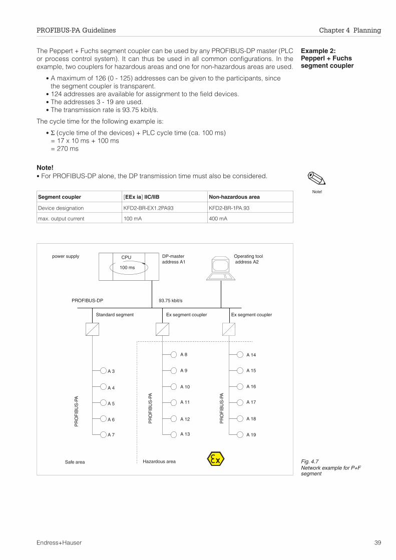
Example 2:Pepperl + Fuchssegment coupler
The Peppert + Fuchs segment coupler can be used by any PROFIBUS-DP master (PLCor process control system). It can thus be used in all common configurations. In theexample, two couplers for hazardous areas and one for non-hazardous areas are used.
• A maximum of 126 (0 - 125) addresses can be given to the participants, sincethe segment coupler is transparent.
• 124 addresses are available for assignment to the field devices.• The addresses 3 - 19 are used.• The transmission rate is 93.75 kbit/s.
The cycle time for the following example is:
• Σ (cycle time of the devices) + PLC cycle time (ca. 100 ms)= 17 x 10 ms + 100 ms= 270 ms
Note!• For PROFIBUS-DP alone, the DP transmission time must also be considered.
Segment coupler [EEx ia] IIC/IIB Non-hazardous area
Device designation KFD2-BR-EX1.2PA93 KFD2-BR-1PA.93
max. output current 100 mA 400 mA
power supply CPU
100 ms
DP-masteraddress A1
93.75 kbit/sPROFIBUS-DP
Standard segment Ex segment coupler Ex segment coupler
A 14
A 15
A 16
A 17
A 18
A 19
Hazardous areaSafe area
A 13
A 12
A 11
A 10
A 9
A 8
A 3
A 4
A 5
A 6
A 7
PR
OF
IBU
S-P
A
PR
OF
IBU
S-P
A
PR
OF
IBU
S-P
A
Operating tooladdress A2
Fig. 4.7Network example for P+Fsegment
Note!
PROFIBUS-PA Guidelines Chapter 4 Planning
Endress+Hauser 39

Example 3:Siemens PA-link
The Siemens PA-link can be used by any PROFIBUS-DP master (PLC or process controlsystem). Three links are used in the example: two links for hazardous areas and one fornon-hazardous areas. Two segment couplers for non-hazardous areas are connected tothe link for non-hazardous areas. Similarly two segment couplers for hazardous areasare connected to the hazardous area link.
• A maximum of 126 addresses can be assigned to the participants on thePROFIBUS-DP system.
• A maximum of 30 addresses (address range 3 - 126) can be assigned in thePROFIBUS-PA segments connected to the link.
• The PROFIBUS-DP addresses 3 -5 are used to address the links.• In the PROFIBUS-PA segments, the addresses 2 -11, 2 - 10 and 2 - 9 are used,
whereby address 2 is reserved for the link in each case.• The transmission rate may be up to 12 Mbit/s.
The cycle time for the following example is:
• Σ (cycle time of the devices) + cycle time per link + PLC-cycle timePROFIBUS-PA segment 1: 9 x 10 ms + 3 x 1 ms + 100 ms = 193 msPROFIBUS-PA segment 2: 8 x 10 ms + 3 x 1 ms + 100 ms = 183 msPROFIBUS-PA segment 3: 7 x 10 ms + 3 x 1 ms + 100 ms = 173 ms
•Note!• For PROFIBUS-DP alone, the DP transmission time must also be considered.
Segment coupler [EEx ia] IIC/IIB Non-hazardous area PA Link (IM157)
Device designation 6ES7-157-0 AD00-0XA0 6ES7-157-0 AC00-0XA0 6ES7-157-0 AC00-0XA0
max. output current 100 mA 400 mA ——
power supply CPU
100 ms
DP masteraddess A1
…12 Mbit/sPROFIBUS-DP
Standard segment Ex segment coupler Ex segment couplerA 4 A 5
Explosion-hazardous areaNon-hazardous area
PA 4
PA 3
PA 11
PA 10
PA 9
A 3
PA 5
PA 6
PA 7
PA 8
PR
OF
IBU
S-P
A
PR
OF
IBU
S-P
A
PR
OF
IBU
S-P
A
Link Link Link
PA 3
PA 4
PA 5
PA 6
SubnetworkSubnetwork Subnetwork
PA 5PA 9
PA 8
PA 7
PA 6
PA 3
PA 4
PA 9
PA 10
PA 8
PA 7
Operating tooladdress A2
PA 2 PA 2 PA 2
Fig. 4.8Network example for Siemens link
Note!
Chapter 4 Planning PROFIBUS-PA Guidelines
40 Endress+Hauser

5 Installation
When installing a PROFIBUS-PA segment, particular attention must be paid to the wiring.The customer has two choices:
• T-box with screw terminals• Cord sets with M12 connector.
In both cases, care must be taken regarding the continuity of the screening and thecorrect termination of the segment.
PROFIBUS-DP systems are usually connected together by means of Sub-D connectors,since there are currently no special components.
The correct installation of the field devices is also important. Since this is beyond thescope of these guidelines, the information should be taken from the correspondingdevice instructions. Finally, the address must be set. The way in which this is done hasan influence on how the segment is subsequently commissioned.
The chapter contains the following sections:
• Cabling in safe areas• Example: screening in safe areas• Example: screening in explosion hazardous areas• Termination• Overvoltage protection• Installation of the devices• Addressing
Note!• Endress+Hauser devices that are suitable for use in explosion hazardous areas are
designed such that the circuit that is connected to the bus exhibits the type ofprotection "intrinsic safety" category ia.
• In contrast to loop-powered devices, four-wire devices have further types ofprotection. This must be taken into account when the device is installed. Since theconnection compartment for the intrinsically safe circuits are designed with type ofprotection EEx d or EEx e, the M12 connector cannot be used for EEx d devices andonly under certain conditions for EEx e devices.
Note!
PROFIBUS-PA Guidelines Chapter 5 Installation
Endress+Hauser 41

5.1 Cabling in safe areas
Screened cable must always be used, see Chapter 3.2. In order to obtain the optimaleffectiveness, the screening should be connected as often as possible to ground.
• The external ground terminal on the transmitter must be connected to ground.• The screening must be grounded at each end of the cable.• In the event of large differences in potential between the individual grounding
points, only on point on the screening should be connected to the ground. Allother screening ends are connected to ground via a capacitor that is suitable forHF applications. (Recommended: ceramic capacitor 10 nF/250 V∼)
Screening the spur/T-box
Use cable glands with good electromagnetic compatibility, if possible with all-roundcontacting of the cable screening (iris spring). A prerequisite is small potentialdifferences, if necessary with equipotential bonding.
• The continuity of the PA cable screening between tapping points must beensured.
• The connection to the screening must be kept as short as possible.
Ideally, cable glands with iris spring should be used to connect the cable screening toT-boxes. The iris spring within the gland connects the screening to the T-box housing.The woven screening lies under the iris spring. When the gland is tighten, the spring issqueezed tight onto the screening, producing good electrical contact between thescreening and the metal housing.
A T-box is to be seen as part of the screening (Faraday cage). This applies in particulardrop-line boxes, when they are connected to a PA device via plug and cable. In suchcases, a metal plug must be used, in which the cable screening is in direct contact withthe plug housing, e.g. a cord set.
BSA
A S B
1µF
100
Ω
T-box (E+H Order Nos.)Aluminium housing IP 67 with 4-pin connector• 017481-0130 with special Pg9 (Iris spring)switchable bus terminator
• 017481-0110 with standard Pg,switchable bus terminator,internal grounding capacitor 10 nF(for capacitive grounding)
Depending upon the T-box, the cable screening is grounded via a 10 nFcapacitor or a special Pg cable gland. If necessary, the capacitor can bereplaced by a wire jumper.
plant ground
next T-box
jumpercable gland with iris spring and/orconnected screening
bus terminatorOFF
Bus cable
bus terminatorON
connector
PROFIBUS-PAdevice via M12connector
Bus cable
Fig. 5.1Optimal EMC connection whenvoltage differences between thegrounding points are small
Chapter 5 Installation PROFIBUS-PA Guidelines
42 Endress+Hauser

5.2 Example: screening in safe areas
Note!• These suggestions may deviate from existing standards (IEC 61158-2) and
guidelines, but produce optimal installation from an EMC point of view.
Example 1Optimal installation when an equipotential bonding system exists
• When the device is not connected directly to the T-box or junction box, use acord set ➀ with M12 connector.
Example 2Isolated installation when no additional grounding is allowed or when the potentialdifferences between the grounding points are too great (the customer's groundingconcept must be observed).
• The segment coupler is the preferred point to fully connect the screening (i.e. notvia a capacitor)
• When the device is not connected directly to the T-box or junction box, use acord set ➀ with M12 connector.
cable gland withiris spring
plug with groundconnection
powersupply/segmentcoupler
field device field device
T-box T-box
ground connectionas short as possible
➀
Plant grounding system (German practice shown here)Fig. 5.2Optimal installation when anequipotential bonding systemexists
standard Pg 9
capacitors:max. 10 nF/250 V~
powersupply/segmentcoupler
field device field device
T-box T-box
➀
Fig. 5.3Alternative installation forisolated version
Note!
PROFIBUS-PA Guidelines Chapter 5 Installation
Endress+Hauser 43

5.3 Example: screening in explosion hazardous areas
The examples which follow reflect German practice - when adapting them for internationaluse, please observe your national regulations.T-boxes and junction boxes must be certified for use in hazardous areas (light bluecolour), type of protection EEx ia. E+H order number: e.g. 017481-0100
Example 1 Common grounding of all devices
• When the device is not connected directly to the T-box or junction box, use acord set ➀ with M12 connector.
• The connection between the screening/housing is not routed into the T-box ➁ andmust be pulled in afterwards.
Example 2 Separate grounding of the devices between safe and hazardous areas.
• When the device is not connected directly to the T-box or junction box, use acord set ➀ with M12 connector.
• The connection between the screening/housing is not routed into the T-box ➁ andmust be pulled in afterwards.
• Use a small capacitor (e.g. 1 nF/1500 V dielectric strength, ceramic) ➂. The totalcapacitance connected to the screening must not exceed 10 nF.
standard Pg 9
➁
powersupply/segmentcoupler
field device field device
T-box T-box
➀
terminatorE+H Order No.017481-0001
Non-hardardousarea
Explosion hazardous area
plant grounding system (German practice shown here)
Fig. 5.4Common grounding of all devices
standard Pg 9
➁
powersupply/segmentcoupler
field device field device
T-box T-box
➂
Non-harzardousarea
Explosion hazardous area terminatorE+H OrderNo.017481-0001
screeningisolatedfromhousing
plant grounding system (German practice shown here)
➀
Fig. 5.5Separate grounding of thedevices between safe andhazardous areas.
Chapter 5 Installation PROFIBUS-PA Guidelines
44 Endress+Hauser

5.4 Termination
The start and end of every PROFIBUS-PA segment must be fitted with a bus terminator.For non-hazardous areas, some T-boxes have an integrated terminating element that canbe switched in when required. If this is not the case, a separate terminator must be used.
• The segment coupler at the beginning of the segment has a built in terminator.• The terminator in the T-box at the end of the segment must be switched in, or a
separate terminator must be used.• T-boxes with switchable terminators may not be used in explosion hazardous
areas. The terminator requires the corresponding FISCO approval and is aseparate unit.
• For a segment with a tree architecture, the bus ends at the device that is thefurthest from the segment coupler.
• For a junction box, the termination can be made at the box, provided that none ofthe connected spurs exceeds 30 m in length.
• If the bus is extended by the use of a repeater, then the extension must also beterminated at both ends.
The beginning and end of the PROFIBUS-DP segment must also be terminated, seeChapter 2. The terminating resistors are already built into most of the connectors on themarket and must only be switched in.
5.5 Overvoltage protection
Depending upon the application, the PROFIBUS-PA segment can also be protectedagainst overvoltages.
• An overvoltage protector is installed immediately after the segment coupler.• An overvoltage protector is installed immediately before every device
(between the device and the T-box).• In the case of hazardous applications, each overvoltage protector must have the
corresponding approval.• The manufacturer's instructions are to be observed when installing.
The overvoltage protectors HAW 560 (standard) and HAW 562 Z (hazardousapplications) are available from Endress+Hauser or direct from the manufacturer (Dehnund Söhne, Neumarkt, Germany)
Overvoltageprotection
Segment coupler
field device
Fig. 5.6PROFIBUS-PA overvoltageprotection system
PROFIBUS-PA Guidelines Chapter 5 Installation
Endress+Hauser 45

5.6 Installation of the devices
The devices must be installed in accordance with the following operating manuals.
Explosion-hazardousareas
All components used in explosion-hazardous applications must have a FISCO approval.If this is not the case, the PROFIBUS-PA segment must be specially approved by theresponsible authorities. All the Endress+Hauser devices listed above have been certifiedin accordance with the FISCO model.
Note!In addition to the general installation guidelines, any special guidelines for installation inexplosion-hazardous areas as well as the guidelines in Chapter 4.1 regarding theinterconnection of devices in explosion hazardous areas must be observed.
Electrical connection Connect up according to the instructions in the device operating manual.
For devices with integrated polarity protection of the bus line, the correct polarity isautomatically selected. If a device without polarity protection is incorrectly wired, then itwill not be recognised by the PLC or operating program. Such an incorrect connection,however, has no damaging effect on the device or the segment.
All Endress+Hauser devices have integrated polarity protection and can becommissioned independent of the actual polarity.
ID Code Device Operating instructions
1501 Cerabar S BA 168P/00/de
1502 Prosonic T BA 166F/00/de
1503 Deltapilot S BA 164F/00/de
1504 Deltabar S BA 167P/00/de
1505 Promag 33/35 BA 029D/06/de
1506 Promass 63 BA 033D/06/de
1507 TMD 834 BA 090R/09/de
1508 Mycom II pH BA 143C/07/de
1509 Mycom II conductivity (ind.) BA 168C/07/de
150A Micropilot FMR 230 V BA 202F/00/de
Micropilot FMR 231 BA 176F/00/de
150B Mycom II conductivity (cond.) BA 144C/07/ de
150C Mypro conductivity BA 198C/07/de
150D Mypro pH BA 198C/07/de
1510 Prowirl 77 BA 037D/06/de
1515 – 1519 Liquisys in Vorbereitung
1514 FXN 164 TI 343F/00/de
RID 261 BA 098R/09/a3
Note!
Chapter 5 Installation PROFIBUS-PA Guidelines
46 Endress+Hauser

5.7 Addressing
Address switchThe device address can be set either locally via DIP switch, via local operating elementsor by the appropriate software, e.g. Commuwin II.
• If future extensions to the network are planned, it makes sense to assignaddresses for the devices that are not yet connected. These can then beconnected per plug and play at a later date.
All Endress+Hauser devices except the temperature sensor TMD 834 are fitted with anaddress switch.
• Switches 1 - 7: Hardware address• Switch 8: Hardware addressing (OFF) or
Software addressing (ON) is used.
The default setting is the software address 126.
Hardware addressingHardware addressing has the advantage that the device can be installed in the segmentimmediately.
1) Set switch 8 to OFF.2) Set an address with switches 1 - 7: the associated values are shown in the table.
Software addressingA software address can be set by calling the DPV1_DDE server in Commuwin II or byusing a PROFIBUS-DP operating tool.
• The device leaves the factory set for software addressing: Default address 126.• This address can be used to check the function of the device and to connect it
into an operating network.• Afterwards, the address must be changed to allow other devices to be
connected to the network.
SWHW
onoff
1 2 3 4 5 6 7 8
2 + 8 = 10
Switch No. 1 2 3 4 5 6 7
Value in position "off" 0 0 0 0 0 0 0
Value in position "on" 1 2 4 8 16 32 64
PROFIBUS-PA Guidelines Chapter 5 Installation
Endress+Hauser 47

Commuwin II To set an address with Commuwin II proceed as follows:
1) Select software addressing at the device: set switch 8 of the address switch to ON2) Start the DVP1 server with a double click on the DPV1 icon in the Commuwin II
program group.3) Select the item Set Address in the menu Configure.4) If a type IM 157 Siemens DP/PA link is being used, enter its DP-address under
PA Link Addr.5) Enter the current address under Old Addr. (= 126 when commissioning).Check the
address entered by clicking on Check Old Address. If a device with the enteredaddress is found, a message to this effect appears under Device ID. Otherwise theerror message "unknown" appears.
6) Enter the new address in New Addr.Check that there is no address conflict byclicking on Check New Address. When the button Set Address becomes active,click on it to assign the new address to the device.
7) When the procedure is completed correctly, the following message appears:"Address successfully changed!"
xx
Pa-Link Addr.:
Device Id:
New Addr.:
Device Id.:
Old ddr.:A
Set Device Address
Help
34
TMD 834
UNKNOWN
Check ld Addr.O
Cancel
Check Ne Addr.wCheck Ne Addr.w
Set AddressSet Address
xx
Pa-Link Addr.:
Device Id:
New Addr.:
Device Id.:
Old ddr.:A
Set Device Address
Help
34
10
TMD 834
UNKNOWN
Check ld Addr.O
Cancel
Check Ne Addr.w
Set Address
Chapter 5 Installation PROFIBUS-PA Guidelines
48 Endress+Hauser

6 System Integration
This chapter is concerned with the information that is required for the system integrationof PROFIBUS-DP and PROFIBUS-PA devices. The chapter is structured as follows:
• Device database files• Data format• Notes on network design• Bus parameters• Tested integrations
6.1 Device database files (GSD)
A device database file contains a description of the properties of the PROFIBUS-PAdevice, e.g. the supported transmission rates and the type and format of the digitalinformation output to the PLC. The bitmap files also belong to the .gsd files. These allowthe measuring point to be represented by an icon. The device database file andcorresponding bitmaps are required by the network design tool of the PROFIBUS-DPnetwork.
Every device is allocated an identity code by the PROFIBUS User Organisation (PNO).This appears in the device data base file name (.gsd). For Endress+Hauser devices, theidentity code is always 15xx, where xx is device dependent. The identity codes of thevarious devices are listed in Table 4.5 in Chapter 4.3.
The full set of device data base files for Endress+Hauser devices can be obtained asfollows:
• INTERNET:Endress+Hauser → http://www.endress.com
Product Avenue → Downloadstreet → Field Communication StreetPNO →http://www.PROFIBUS.com (GSD library)
• As diskette direct from Endress+Hauser: Order No. 943157-0000
Working with GSD filesThe .GSD files must be loaded into a specific subdirectory in the PROFIBUS-DP networkdesign software of your PLC.
• GSD files and bitmaps that are located in the directory "Typdat5x", for example,are required for the planning software STEP7 used by the Siemens S7-300/400PLC family.
• x.200 files and bitmaps that are located in the directory "Extended" are requiredfor the planning software COM ET200 for the Siemens S5.
• The GSD files located in the directory "standard" are for PLCs that support the"identifier byte" (0x94) but not the "identifier format". These are for use e.g. withthe Allen-Bradley PLC5.
More details about the directories used for storing the GSD files can be found in Chapter6.4, which describes the network design.
Device name IDcode.:
GSD Type file Bitmaps
MicropilotFMR 23x
150A(hex)
EH__150A.gsd EH_150Ax.200 EH150A_d.bmpEH150A_n.bmpEH150A_s.bmp
PROFIBUS-PA Guidelines Chapter 6 System Integration
Endress+Hauser 49

6.2 Data format
By using the data exchange service, a PLC can transmit its output data to a field deviceand read the input data from the response telegram. The output data is not evaluated byall devices, see the device operating instructions.
Analogue values If the input data contains analogue measured values, these are usually transmitted in 5bytes to the PLC.
If a device delivers more than one measured value, the measured value telegram isincreased accordingly, see Chapter 2.4. The number of measured values that a devicetransmits is set with the network design tool. Table 4.7 in Chapter 4.6 as well as the deviceoperating manuals summarise the measured values that can be transmitted byEndress+hauser devices.
The measured value is transmitted as a IEEE 754 floating point number, whereby
Measured value = (–1)Sign x 2(E – 127) x (1 + F)
Example: 40 F0 00 00 hex = 0100 0000 1111 0000 0000 0000 0000 0000 binary
Value = (–1)0 x 2(129 – 127) x (1 + 2–1 + 2–2 +2–3)
= 1 x 22 x (1 + 0.5 + 0.25 + 0.125)
= 1 x 4 x 1.875
= 7.5
Not all PLCs support the IEEE 754 format. For this reason a conversion module must oftenbe used or written.
Level limit signals If the field device outputs a level limit signal, e.g. FXA 164 with Liquiphant, the informationis transmitted in 2 bytes as follows.
An exact description of the transmission format is to be found in the operating instructions.
bytes 1 bytes 2 bytes 3 bytes 4 bytes 5
Measured value as IEEE 754 floating point number Status
D15 D14 D13 D12 D11 D10 D9 D8 D7 D6 D5 D4 D3 D2 D1 D0
Sign Exponent (E) Fraction (F)
27
26
25
24
23
22
21
20
2-1
2-2
2-3
2-4
2-5
2-6
2-7
Fraction (F)
2-8 2-9 2-10 2-11 2-12 2-13 2-14 2-15 2-16 2-17 2-18 2-19 2-20 2-21 2-22 2-23Fig. 6.1IEEE-754 floating point number
bytes 1 bytes 2
Digital value (USGN8) Status
Chapter 6 System Integration PROFIBUS-PA Guidelines
50 Endress+Hauser

StatusTable 6.2 lists the status messages that can be transmitted by Endress+hauser devices.The status codes correspond to the PROFIBUS profiles "PROFIBUS-PA Profile forProcess Control Devices - General Requirements" V 2.0.
The full table is supported by the flowmeters Promag, Promass and Prowirl. All otherdevices support only Codes 00Hex, 40Hex and 80Hex.
Status-Code
Significance Devicestatus
Implimented
Flow Other
00 Hex Non-specific BAD x x
04 Hex Configuration error BAD x
08 Hex Not connected BAD x
0C Hex Device failure BAD x
10 Hex Sensor failure BAD x
14 Hex No communication (last usable value) BAD x
18 Hex No communication (no usable value) BAD x
1C Hex Out-of-order BAD x
20 Hex Configuration error "variable not" BAD x
40 Hex Non-specific (Simulation) UNCERTAIN x x
44 Hex Last usable value UNCERTAIN x
48 Hex Substitute set UNCERTAIN x
4C Hex Initial value UNCERTAIN x
50 Hex Sensor conversion not accurate UNCERTAIN x
54 Hex Engineering unit range violation UNCERTAIN x
58 Hex Subnormal UNCERTAIN x
5C Hex Configuration error, value adapted UNCERTAIN x
80 Hex OK GOOD x x
81 Hex LOW_LIM (alarm active) GOOD x
82 Hex HI_LIM (alarm active) GOOD x
84 Hex Active block alarm GOOD x
88 Hex Active advisory alarm GOOD x
8C Hex Active critical alarm GOOD x
90 Hex Unacknowledged block alarm GOOD x
94 Hex Unacknowledged advisory alarm GOOD x
98 Hex Unacknowledged critical alarm GOOD x
9C Hex good local operation possible GOOD x
AC Hex Initiate fail-safe GOOD xTable 6.1Status messages
PROFIBUS-PA Guidelines Chapter 6 System Integration
Endress+Hauser 51

6.3 Notes on network design
In general, the design of a PROFIBUS-DP network proceeds as follows:
1. The network participants are stipulated in a PROFIBUS-DP network design program.The network is configured off-line with the planning software To this end, the GSDfiles are first loaded into the specified directory of the program.
2. The PLC application program must now be written. This is done using themanufacturer's software. The application program controls the input and output ofdata and determines where the data are to be stored. If necessary, an additionalconversion module must be used for PLCs that do not support the IEEE 754floating point format. Depending upon the way the data is stored in the PLC(LSB or MSB), a byte swapping module may be required.
3. After the network has been designed and configured, the result is loaded into thePLC as a binary file.
4. When the PLC configuration is complete, the system can be started up. The masteropens a connection to each individual device. By using a Class 2 master, e.g.Commuwin II, the devices parameters can now be set.
System Master PROFIBUSconfigurationsoftware
System-Programming-software
IEEEconv.-block
bytesswap
Siemens S5 … seriesS7 … series
COM PROFIBUSHW ConfigHW Config
Step 5Step 7PCS 7
FB 201______
no
Allen Bradley PLC-5
SLC-500
SST PROFIBUSConfiguration Tool
RS Logix-5
RS Logix-500
___
___
no
Schneider TSX Premium Sycon Hilscher PL7 Pro ___ yes
Schneider Quantum Modicon Quantum Sycon Concept ___ yes
Klckner-Moller PS 416 CFG-DP S 40 ___ yes
ABB Freelance Field controller Digitool Digitool ___ yes
Bosch ZS 401 Win DP Win SPS ___ yes
––– not necessary, since integrated in software
Table 6.2Examples of network designsoftware
Chapter 6 System Integration PROFIBUS-PA Guidelines
52 Endress+Hauser

6.4 Tested system integrations
Table 6.3 lists those PROFIBUS-DP systems that have been successfully tested byEndress+Hauser. A detailed description of the network design as well as information onother systems is available on request.
PLC Interface DP/PA-Coupler
Siemens S7-300 315-2DP P+F
Siemens S7-300 315-2DP Siemens
Siemens S7-300 315-2DP Siemens DP/PA link
Siemens S7-400 414-2DP P+F
Siemens S7-400 414-2DP Siemens
Siemens S7-400 414-2DP Siemens DP/PA link
Siemens S5-135U IM 308C P+F
Siemens S5-135U IM 308C Siemens
Siemens S5-155U IM 308C P+F
Siemens S5-155U IM 308C Siemens
Siemens S5-155U IM 308C Siemens DP/PA link
Allen Bradley PLC-5 SST-PFB-PLC5 P+F
Allen Bradley PLC-5 SST-PFB-PLC5 Siemens DP/PA link
Allen Bradley SLC 500 SST-PFB-SLC P+F
Mitsubshi Melsec AnS A1S-J71PB92D P+F
Schneider TSX Quantum 140 CRP 81100 P+F
Schneider Premium TSX PBY 100 P+F
HIMA H41 (MODBUS) PKV 20-DPM P+F
Klckner-Mller PS 416 PS416-NET-440 P+F
ABB Freelance 2000 Fieldcontroller P+F
Softing OPC Server Profiboard/Proficard P+F
Bosch CL 350 P BM DP12 P+F
Bosch CL 350 P BM DP12 Siemens DP/PA linkTable 6.3Summary of tested systems
PROFIBUS-PA Guidelines Chapter 6 System Integration
Endress+Hauser 53

Table 6.5 summarises the most important DP-parameters of various systems.
PLC/interface DP/PA coupler No of slaves per DPinterface
DP telegram length
Siemens S7-300315-2 DP
P+F 64 244 bytes
Siemens 64 244 bytes
Siemens DP/PA link max. 64 links withmax. 24 slaves each
1)122 bytes read122 bytes write
Siemens S7-400414-2 DP
P+F 96 244 bytes
Siemens 96 244 bytes
Siemens DP/PA link max. 96 links withmax. 24 Slaves
1)122 bytes read122 bytes write
Siemens S5-135UIM 308C
P+F 122 244 bytes read244 bytes write
Siemens 122
Siemens S5-155UIM 308C
P+F 122 244 bytes read244 bytes write
Siemens 122
Siemens DP/PA link max. 20 links withmax. 24 slaves each
1)122 bytes read122 bytes write
Allen Bradley PLC-5SST-PFB-PLC5
P+F 125 244 bytes read244 bytes write
Siemens DP/PA link max. 125 links withmax. 48 slaves each1)
Allen Bradley SLC 500SST-PFB-SLC
P+F 96 244 bytes read244 bytes write
Mitsubishi Melsec AnSA1S-J71PB92D
P+F 60 244 bytes read244 bytes write
Schneider TSX Quantum+ 140 CRP 81100
P+F 125 244 bytes read244 bytes write
Schneider Premium +TSX PBY 100
P+F 125 max. 244 bytes
HIMA H41 (MODBUS) +PKV 20-DPM
P+F 125 max. 244 bytes
Klckner-Mller PS 416+PS416-NET-440
P+F 30, 126 with repeaters 244 bytes read244 bytes write
ABB Freelance 2000 +Fieldcontroller
P+F 125 244 bytes read244 bytes write
Bosch CL 350 P +BM DP12
P+F 125 244 bytes read244 bytes write
Siemens DP/PA link max. 125 links withmax. 48 slaves each
1)
1)dependent on the telegram length of the slaves
Table 6.4Summary of tested systems
Chapter 6 System Integration PROFIBUS-PA Guidelines
54 Endress+Hauser

6.5 Bus parameters
Baudrate,PROFIBUS-DP devices
Endress+Hauser's PROFIBUS-DP devices support baudrates up to 12 Mbit/s. Thebaudrate is automatically adjusted to that used by the master.
Operating programCommuwin II.
If Commuwin II is used as a Class 2 master to transmit acyclic values, then the busparameters of the DPV1 DDE server must be matched to those of the segment coupler(or those of the network for PROFIBUS-DP applications).
Depending upon the segment coupler, the corresponding PROFIBUS-DP baudrate mustbe set in the network design software.
Pepperl + Fuchs 93.75 kbit/sSiemens 45.45 kbit/sPA Link (Siemens) 9.6 kbit/s – 12 Mbit/s
The baudrate of Commuwin II must be set in the DPV1 DDE server.
1. Start the server DPV1 from the File Manager or Explorer by a double click on theDPV1 icon in the Commuwin II program group.
2. Open the item Parameter Settings in the Configure menu. The baudrate can nowbe adjusted.
3. After the baudrate has been entered, update the bus parameters by clicking onDefault.
4. If necessary optimise the parameters as per Table 6.3 or the manufacturer'sspecifications.
xx
Local Station ddr.:A
Baudrate [kBd]:
Slot Time [TSL]:
Bit Times
Mi St Delay [minTSDR]:n
Ma St Delay [max TSDR]:x
Set p Time [TSET]:u
Target otation Time [TTR]:R
Higest S ation Addr. [HSA]:t
Gap Update Factor:
Max. Retry imit::L
Communication Parameter Settings
Default
Help
1
45,45
640 [6882 µs]
[119 µs]
[4302 µs]
[1022 µs]
[107527 µs]
11
400
95
10000
126
1
3
Cancel
OK
Segment coupler Siemens P+F "old" P+F "new"1)
Slot time 640 10000 4095
Max. station delay time 400 1000 100
Min. station delay time 11 255 22
Setup time 95 255 150
GAP update factor 1 1 1
Max. retry limit 3 5 5
Target rotation time2) (TTR) TTR calculated by master + 20 000 bit times
1)The segment coupler has the label 12-3-98
2)Value must be set in all masters.
Table 6.5Bus parameters for Commuwin II
PROFIBUS-PA Guidelines Chapter 6 System Integration
Endress+Hauser 55

7 Device Configuration
There are two reasons for configuring a PROFIBUS-PA device:
• the adjustment of the operating parameters of the device to calibrate it for theapplication at hand. In this case the corresponding operating instructions shouldbe used.
• the adjustment of the profile parameters of the device in order to e.g. scale orsimulate the cyclic measured value output to the PLC.
The operating parameters can be set using the local operating elements of the device,if it is so equipped. This is not described in this manual. These parameters can also beadjusted by the acyclic services of the PROFIBUS-DP system, e.g. with the Commuwin IIoperating and display program. Profile parameters are accessible only through the cyclicservices of the PROFIBUS-DP system.
This chapter describes the operating concept of the PROFIBUS-PA devices. It issubdivided as follows:
• PROFIBUS-PA block model• Device management• Physical block• Transducer block• Function block• Operating program Commuwin II.
Note!The figures and tables in this chapter mostly refer to PROFIBUS-PA Profile 3.0 which willbe released shortly.
Note!
Chapter 7 Device Configuration PROFIBUS-PA Guidelines
56 Endress+Hauser
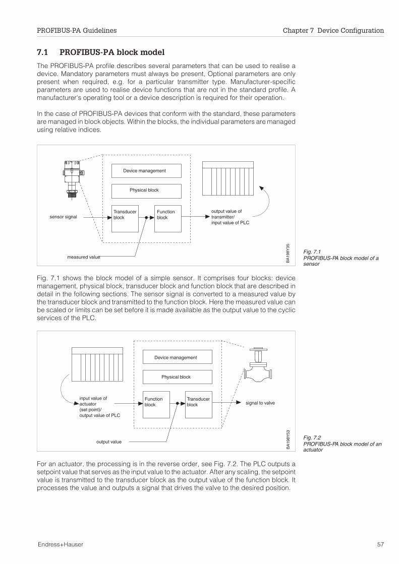
7.1 PROFIBUS-PA block model
The PROFIBUS-PA profile describes several parameters that can be used to realise adevice. Mandatory parameters must always be present, Optional parameters are onlypresent when required, e.g. for a particular transmitter type. Manufacturer-specificparameters are used to realise device functions that are not in the standard profile. Amanufacturer's operating tool or a device description is required for their operation.
In the case of PROFIBUS-PA devices that conform with the standard, these parametersare managed in block objects. Within the blocks, the individual parameters are managedusing relative indices.
Fig. 7.1 shows the block model of a simple sensor. It comprises four blocks: devicemanagement, physical block, transducer block and function block that are described indetail in the following sections. The sensor signal is converted to a measured value bythe transducer block and transmitted to the function block. Here the measured value canbe scaled or limits can be set before it is made available as the output value to the cyclicservices of the PLC.
For an actuator, the processing is in the reverse order, see Fig. 7.2. The PLC outputs asetpoint value that serves as the input value to the actuator. After any scaling, the setpointvalue is transmitted to the transducer block as the output value of the function block. Itprocesses the value and outputs a signal that drives the valve to the desired position.
BA
198Y
35
Device management
Physical block
Transducerblock
Functionblock
output value oftransmitter/input value of PLC
sensor signal
measured valueFig. 7.1PROFIBUS-PA block model of asensor
BA
198Y
53
signal to valve
output value
Transducerblock
Physical block
Device management
Functionblock
input value ofactuator(set point)/output value of PLC
Fig. 7.2PROFIBUS-PA block model of anactuator
PROFIBUS-PA Guidelines Chapter 7 Device Configuration
Endress+Hauser 57

Block structure The parameters assigned to the individual blocks use the data structures and dataformats that are specified in the PROFIBUS standard. The structures are designed suchthat the data are stored and transmitted in an ordered and interpretable manner.
All parameters in the PROFIBUS-PA profile, whether mandatory or optional, are assignedan address (slot/index). The address structure must be maintained, even if optionalparameters are not implemented in a device, This ensures that the relative indices in theprofile are also to be found in the devices.
Standard parameters With the exception of the device management, the standard parameters are to be foundat the beginning of every block. They are used to identify and manage the block. Theuser can access these parameters using the acyclic services, e.g. by means of theCommuwin II operating program. Table 7.1 lists and briefly explains the standardparameters.
Rel.Index
Parameter Description R/W M/O
1 BLOCKOBJECT Contains the type of block, e.g. function block, as wellas further classification information in the form of threestorey a tree structure.
R M
2 ST_REV Event counter: Counts every access to a static blockparameter. Static parameters are those deviceparameters that are not influenced by the process.
R M
3 TAG_DESC Text for unambiguous identification of the block: In thephysical block, TAG_DESC is used as the measuringpoint tag.
R, W M
4 STRATEGY A code number that allows blocks to be groupedtogether.
R, W M
5 ALERT_KEY Identifies the part of the plant where the transmitter islocated. Helps in the localisation of events.
R, W M
6 MODE_BLK Describes the operating mode of the block.Three parameters are possible:
actual modepermitted mode andnormal mode
MODE_BLK allows a functional check of the block. Ifthe block is faulty, a default value can be output.
R, W M
7 ALARM_SUM Contains the current status of the block alarms. At themoment only the following are signalled: the change ofa static parameter (10 s) and the violation of theadvisory and critical limits in the analog input block.
R, W M
8 BATCH Provided for batch processes as per IEC 61512 Part 1.Is only to be found in function blocks.
R, W M
R = Read, W = Write, M/O = Mandatory/Optional parameter
Table 7.1Standard block parameters
Chapter 7 Device Configuration PROFIBUS-PA Guidelines
58 Endress+Hauser

7.2 Device management
The device management comprises the directory for the block and object structure ofthe device. It gives information about:
• which blocks are present in the device• where the start addresses are located (slot/index)• how many objects each block holds.
By using this information, the application program of the master can find and transmitthe mandatory and optional parameters of a profile block, see Fig. 7.3.
The device management is always located in slot 1 starting at index 0. It contains thefollowing parameters:
DIRECTORY_OBJECT_HEADER
Device Management (Slot 1) Slot x Slot y
DIR_ID
Index j Index m
Index k Index n
Index l
INDEX_PB
REV_NUMBER
FUNCTION BLOCK 1 FUNCTION BLOCK 2
PHYSICAL BLOCK 1 TRANSDUCER BLOCK 2
TRANSDUCER BLOCK 1
NUM_PB
NUM_DIR_OBJ
INDEX TB
NUM_DIR_ENT
NUM_TB
FIRST_COMP_LIST_DIR_ENTRY
INDEX_FB
....
NUM_COMP_LIST_DIR_ENTRY
NUM_FB
BLOCK_PTR_#
COMPOSITE_LIST_DIRECTORY_ENTRIES
BLOCK_PTR_1BLOCK_PTR_2BLOCK_PTR_3BLOCK_PTR_4
COMPOSITE_DIRECTORY_ENTRIES
COMPOSITE_DIRECTORY_ENTRIES_CONTINUOUS
BA
198Y
36 Fig. 7.3Structure and function of thedevice managementDevice management block
Abs.Index
Parameter Description R/W M/O
8 SOFTWARE_REVISION Software version implemented in device R M
0 DIRECTORY_OBJECT_HEADER Header comprising(see Fig. 7.3 for parameter names)
Directory code (=0)Directory version numberNumber of directory objectsNumber of directory entriesIndex of the first directory entryNumber of block types
R M
1 COMPOSITE_LIST_DIRECTORY_ENTRIES/
COMPOSITE_DIRECTORY_ENTRIES
Pointer:Abs. index + offset, 1st physical blockNumber of physical blocksAbs. index + offset, 1st transducer blk.Number of transducer blocksAbs. index + offset, 1st function blockNumber of function blocksPointer 1 to 1st blockPointer 2 to 2nd block.....Pointer # to #th block
W M
2 COMPOSITE_DIRECTORY_ENTRIES_CONTINUOUS
Continuation of COMPOSITE_DIRECTORY_ENTRIES or start of thepointer entries
W M
R = Read, W = Write, M/O = Mandatory/Optional parameter
Table 7.2Device management parameters
PROFIBUS-PA Guidelines Chapter 7 Device Configuration
Endress+Hauser 59

7.3 Physical block
The physical block contains the properties of the field device. These are deviceparameters and functions that are not dependent upon the measurement method. Thisensures that the function and transducer blocks are independent of the hardware.
The physical block contains the following parameters:
Rel.Index
Parameter Description R/W M/O
8 SOFTWARE_REVISION Software version implemented in the device R M
9 HARDWARE_REVISION Hardware version implemented in the device R M
10 DEVICE_MAN_ID Manufacurer's identity code W M
11 DEVICE_ID Manuafacturer's name for the device R M
12 DEVICE_SER_NUM Serial number of the device R M
13 DIAGNOSIS Bit-coded uniform diagnostic messages R M
14 DIAGNOSIS_EXTENSION Manufacturer's diagnostic messages R O
15 DIAGNOSE_MASK Bit mask that indicates the DIAGNOSIS bitssupported.
R M
16 DIAGNOSIS_EXTENSION_MASK Bit mask that indicates theDIAGNOSIS_EXTENSION bits supported
R O
17 DEVICE_CERTIFICATION Text describing the device certification R, W O
18 WRITE_LOCKING On/off switch for write protection R, W O
19 FACTORY_RESET Command that resets the device e.g. to itsfactory settings
W O
20 DESCRIPTOR User text that describes the function of a devicewithin an application
R, W M
21 DEVICE_MESSAGE User text that describes the function of thedevice within its application or device unit
R, W M
22 DEVICE_INSTAL_DATE Installation date of the device R, W M
23 LOCAL_OP_ENA Enable/Disable of local operation R, W M
24 IDENT_NUMBER Specifies the configuration behaviour of thedevice on acknowledgement of the deviceidentity code.dar
R, W M
25 HW_WRITE_PROTECTION Shows the setting of a hardware jumper thatactivates a general write protection.
R, W M
R = Read, W = Write, M/O = Mandatory/Optional parameter
Table 7.3Physical block parameters
Chapter 7 Device Configuration PROFIBUS-PA Guidelines
60 Endress+Hauser

Diagnostic messagesThe diagnostic messages are divided into standard (DIAGNOSE) andmanufacturer-specific blocks (DIAGNOSE_EXTENSION). A diagnostic message issupported when a "1" is to be found in the corresponding bit mask (_MASKE). Thefollowing statuses are to be found in the standard diagnostics.
In the case of Endress+Hauser devices, a device error message is available when Bit 7of Octet 4 is set (=1). They are stored as 6 bytes in slot 1. For further information, see thecorresponding field device.
Octet Bit Parameter Description
1 0 DIA_HW_ELECTR Fault in device electronics hardware
1 DIA_HW_MECH Mechanical device fault
2 DIA_TEMP_MOTOR Motor temperature too high
3 DIA_TEMP_ELECTR Electronics temperature too high
4 DIA_MEM_CHKSUM Memory error
5 DIA_MEASUREMENT Measured value error
6 DIA_NOR_INIT Device not initialised
7 DIA_INIT_ERR Intialisation error
2 0 DIA_ZERO_ERR Zero point error
1 DIA_SUPPLY Load supply error
2 DIA_CONF_INVAL Invalid configuration
3 DIA_WARMSTART Warm start in progress
4 DIA_COLDSTART Cold start in progress
5 DIA_MAINTENANCE Maintenance necessary
6 DIA_CHARACT Invalid characteristic
7 IDENT_NUMBER_VIOLATION Violation of identity number
3 0 - 7 reserved
4 0 - 6 reserved
7 EXTENSION_AVAILABLE Manufacturer's diagnostic messages available Table 7.4Standard diagnostic messages
PROFIBUS-PA Guidelines Chapter 7 Device Configuration
Endress+Hauser 61

7.4 Transducer blocks
Transducer blocks stand as separating elements between the sensor (or actuator) andthe function block. They process the signal from the sensor (or actuator) and output avalue that is transmitted via a device-independent interface to the function block.
The transducer blocks reflect the measurement (or actuator) principles. Moreover, blocksalso exist for devices with a binary input or output signal- Fig. 7.4. shows the transducerblocks that are currently available. A description of the parameters can be taken fromBA 124F (Commuwin II) or the appropriate device operating instructions.
Fig. 7.5 shows an example for a hydrostatic level transmitter. The functions indicated canbe operated via the acyclic services. When Commuwin II is used Endress+Hauserdevices can also be operated with the E+H matrix or graphic operation interface.
Measurementequipment
A (Analysis) L (Level)P (Pressure,
p)∆ T (Temperature)F (Flow)
Differentialpressure
Electromagnetic
Vortex
Ultrasonic
Positivedisplacement
Coriolis
Thermal
Resistancethermometer
Thermocouple
Pyrometer
Hydrostatic
Displacement
Ultrasonics
Microwave
Capacitance
Vibration
Fig. 7.4Summary of measuring methodsimplemented in transducerblocks (1999)
p
l
EM
PT
Y_C
AL
FU
LL_C
AL
DE
NS
ITY
_FA
CTO
R
PR
ES
SU
RE
(MA
X_P
RE
SS
UR
E)
(MIN
_PR
ES
SU
RE
)(U
NIT
)
LEV
EL
VO
LUM
ES
TAT
US
ZE
RO
_OF
FS
ET
LIN
_TY
PE
LIN
EA
RIS
ATIO
NM
AX
_NU
M_S
UP
PO
RT
ED
MA
X_N
UM
_NE
ED
IND
EX
INP
UT
_VA
LUE
OU
T_V
ALU
E
LIN
EA
RIS
ATIO
NC
YL_
DIA
ME
TE
RC
YL_
VO
LUM
E
l
v
l
v
Parameters can be read and written using the acyclic services
Sensorsignal
Measuredvalue
Fig. 7.5Example for the transducer blockof a hydrostatic level transmitter
Chapter 7 Device Configuration PROFIBUS-PA Guidelines
62 Endress+Hauser

7.5 Function blocks
The function blocks contain the basic automation functions. Since the applicationprogram demands that a cyclic value always behaves in the same manner, the blocksare designed to be as independent as possible from the actuator/sensor and the fieldbus.For transmitters there are currently three function blocks, which are described in moredetail in the following pages.
Analog input blockThe analog input block is fed by the transducer block of a particular transmitter. The firstfunction in the processing chain allows the measured value to be replaced by a simulatedvalue when required. Then the input value is normalised to a value between 0 and 1.Normally, the lower and upper range values of the transducer block are used for scaling.No limits are set on the scaling values, and values beyond the end-values are correctlyscaled.
The resulting value can now be linearised if required. Depending upon the setting, forexample, a root function, a linearisation table or a preset linearisation might be activated.For Endress+Hauser devices with Profile 2.0, these functions are currently mapped onthe transducer block. For devices with Profile 3.0 (available early in 2000) the linearisationwill be mapped on the analog input block as described here.
The normalised value is now scaled. If the "OUT" value offered to the PLC is to be identicalwith the input value of the transducer block, then the lower and upper range values fromthe transducer block must again be used for scaling. Alternatively, other values can beused, e.g. 1 – 32768 (20 – 215) in 15-bit resolution.
An integration time and limits can now be assigned to the output value. Violations of thelimits are signalled in the status byte. Finally the status of the output value is checked.The safety functions are activated when the status "BAD" or the mode "out of service" isdetected. On fault condition a default value can be used as output value. The cyclicmeasured value made available to the DP master comprises the output value OUT andthe status.
1
1
1
0
PV OUT
0
PV
_SC
ALE
PV
_SC
ALE
_UN
ITP
V_S
CA
LE_M
INP
V_S
CA
LE_M
AX
OU
T_S
CA
LEO
UT
_SC
ALE
_UN
ITO
UT
_SC
ALE
_MIN
OU
T_S
CA
LE_M
AX
HI_
HI_
LIM
HI_
LIM
LO_L
IMLO
_LO
_LIM
ALA
RM
_HY
S
HI_
HI_
ALM
HI_
ALM
LO_A
LMLO
_LO
_ALM
SIM
ULA
TIO
NV
ALU
ES
TAT
US
ON
_OF
F
LIN
_TY
PE
CH
AN
NE
L
NO
RM
AL_
MO
DE
PE
RM
ITT
ED
_MO
DE
AC
TU
AL_
MO
DE
FS
AF
E_T
YP
EF
SA
FE
_VA
LUE
MO
DE
_BLK
MA
N
MAN
PV
_TIM
E
1
τ FAILSAFE
OUT
MODE/STATUS
AUTO
O/S
BA
198Y
39
Input scaling Linearisation Outputscaling
Damping Limit Safety logic
Parameters can be read and written using the acyclic services
Alarms are indicated in the status byte
Simulation
Fig. 7.6Schematic diagram of the analog input block
PROFIBUS-PA Guidelines Chapter 7 Device Configuration
Endress+Hauser 63

Totalisor block The totalisor block is used when a process variable must be summed over a period oftime. This is the case for flowmeters, whereby for Endress+Hauser devices totalisors canbe activated for both volume and mass measurements. The block is fed by the transducerblock of a particular transmitter, which provides a measured value and status.
The first function in the processing chain is a safety logic that checks the status of theinput value. If the status is "BAD", the safety function is activated. Three options are nowavailable: the bad value can be used for totalising, the last valid value can be used orthe totaliser can be switched off. The safety function remains active until the statuschanges to "OK".
The next function is the selection of counting mode. Four options are available: all values,positive values only, negative values only, no values at all. The value is now totalised bythe counter. The counter can be set to work with equidistant timing or over timedifferences. It can also be reset to a preset value or zero.
Limits may also be assigned to the totalisor. Violations of the limits are signalled in thestatus byte. Finally the status of the output value is checked. If the mode "out of service"is detected, the safe functions are activated. On fault condition a default value can beused as output value. The cyclic measured value made available to the DP mastercomprises the output value TOTAL and the status.
SE
T_T
OT
PR
ES
ET
_TO
TU
NIT
_TO
T
HI_
HI_
LIM
HI_
LIM
LO_L
IMLO
_LO
_LIM
ALA
RM
_HY
S
HI_
HI_
ALM
HI_
ALM
LO_A
LMLO
_LO
_ALM
MO
DE
_TO
T
CH
AN
NE
L
NO
RM
AL_
MO
DE
PE
RM
ITT
ED
_MO
DE
AC
TU
AL_
MO
DE
FAIL
_TO
T
MO
DE
_BLK
MAN
MA
N_V
ALU
E
ΣFAILSAFE
MEMORY
HOLD
RUNTOTAL
MODE/STATUS
AUTO
BALANCEDPOS_ONLYNEG_ONLYHOLD
O/SB
A19
8Y40
Counting mode Counter LimitSafety logic
Parameters can be read and written using the acyclic services
Alarms are indicated in the status byte
Safety logic
Fig. 7.7Schematic diagram of the totaliser block
Chapter 7 Device Configuration PROFIBUS-PA Guidelines
64 Endress+Hauser

Discrete input blockThe discrete input block is used for limit switched, e.g. the Liquiphant (in connection withthe FXA 164 NAMUR/PROFIBUS-PA interface). The analog input block is fed by atransducer block of a particular transmitter.
The first function in the processing chain allows the measured value to be replaced bya simulated value when required. Afterwards the resulting signal can be inverted.
Finally the status of the output value is checked. The safety functions are activated whenthe status "BAD" or the mode "out of service" is detected. On fault condition a defaultvalue can be used as output value. The cyclic measured value made available to thePROFIBUS-DP master comprises the output value OUT_D and the status.
SIM
ULA
TIO
NV
ALU
ES
TAT
US
ON
_OF
F
CH
AN
NE
L
NO
RM
AL_
MO
DE
PE
RM
ITT
ED
_MO
DE
AC
TU
AL_
MO
DE
FS
AF
E_T
YP
EF
SA
FE
_VA
L_D
MO
DE
_BLK
INV
ER
T
MA
N
MAN
FAILSAFE
OUT_D
MODE/STATUS
AUTO
O/SINVERT
BA
198Y
36
Parameters can be read and written using the acyclic services
Fig. 7.8Schematic diagram of thediscrete input block
PROFIBUS-PA Guidelines Chapter 7 Device Configuration
Endress+Hauser 65

7.6 Operating program Commuwin II.
PROFIBUS-PA devices can be operated by the operating program Commuwin II (fromsoftware version 2.0 upwards) A full description of Commuwin II is to be found in operatinginstructions BA 124F. All the standard functions of Commuwin II are supported exceptingenvelope curves for ultrasonic and microwave devices. The device settings can be madeusing the operating matrix or graphic operating interface.
Requirements Commuwin II runs on an IBM-compatible PC or Laptop. The computer must be equippedwith a PROFIBUS interface, i.e. PROFIBOARD for PCs and PROFICARD for laptops.During the system integration, the computer is registered as a Class 2 master.
Operation The PA-DPV1 server must be installed. The connection to Commuwin II is opened fromthe PA-DPV1 server.
• Generate a live list with "Tags"
• E+H operation is selected by clicking on the device name, e.g. CERABAR S.• Profile operation is selected by clicking on the appropriate tag,
e.g. AI: PIC 205 = Analog input block Cerabar S.• The settings are entered in the device menu.
Device menu The device menu allows matrix or graphical operation to be selected.
• In the case of matrix operation, the device or profile parameters are displayed ina matrix. A parameter can be changed when the corresponding matrix field isselected.
• In the case of graphical operation, the operating sequence is shown in a series ofpictures with parameters. For profile operation, the pictures Diagnosis, Scaling,Simulation and Block are of interest.
The device parameters are set in accordance with the corresponding operatinginstructions. Tables of profile functions are also to be found here. The parameter blocksare adapted to the transmitters: not all the functions shown in Fig 7.5 to Fig. 7.8 need beimplemented.
Devices from other vendors can also be operated via the profile parameters. In this case,standardised transducer, function or physical blocks appear.
Off-line operation(E+H, Samson)
Commuwin also allows the devices to be configured off-line. After all parameters havebeen entered, the file generated can be loaded into the connected device.
Up-/download(E+H, Samson)
This function allows the parameters of an already configured device to be loaded andstored in Commuwin II. If several devices (with the same software version) have to beconfigured in the same way, the parameters can now be downloaded into the devices.
007 - FEB 24
008 - CERABAR S
PHY_20: LIC 123LEVEL: LIC 123AI: LIC 123
PHY_30: PIC 205Pressure PIC 205AI: PIC 205
....
....
Selection of thedevice operation
Selection of profileoperation
Chapter 7 Device Configuration PROFIBUS-PA Guidelines
66 Endress+Hauser

Fig. 7.9 shows the graphic operation picture for the basic calibration of the Deltapilot S.
Fig. 7.10 shows the graphical operation for the scaling of the Deltapilot S. By selectingthe device profile "AI transmitter block" (acknowledge with ↵) the parameters PV_SCALEand OUT_SCALE can be set. Please note that for DPV1 Version 2.0, the unit is nottransmitted with the measured value. The setting of the PV unit also has no effect on theoutput value OUT.
The operating picture "Diagnosis" shows the current status of the device. "Simulation"allows a measured value to be simulated, "Block" displays the current setting of the modeblock.
BA
198D
43
Fig. 7.9Basic calibration of the Deltapilotusing Commuwin II
BA
198D
43
Fig. 7.10Scaling of the PA output of alldevices using Commuwin II
PROFIBUS-PA Guidelines Chapter 7 Device Configuration
Endress+Hauser 67

8 Trouble-Shooting
This chapter contains a summary of the most frequent faults and questions concerningPROFIBUS that have been dealt with by our service department. It is subdivided asfollows:
• Commissioning• PLC network design• Data transmission• Commuwin II
8.1 Commissioning
Question/Fault Cause/Remedy
How can I assign an address to adevice?
With the exception of the temperature sensor TMD 834, allEndress+Hauser devices have an address switch that allowshardware or software addressing.
For software addressing (or for the TMD 834) a PROFIBUS-DPoperating tool is required, e.g. the DPV1 server in Commuwin II. Itsuse is described in Chapter 5.7
Where is the device terminationswitch?
There is no termination switch on the device itself.
The bus is terminated by using a separate terminator or a T-box with aswitchable terminating element.
In the case of explosion hazardous applications, a separate,certified terminator must be used!
When a device is added to thebus, the segment fails.
The segment coupler supplies a defined maximum output current tothe segment. Every device requires a particular basic current (seeChapter 4.2). If the sum of the basic currents exceeds the outputcurrent of the coupler, the bus become unstable.
Diagnosis: Measure the current consumption of the devices with anammeter.
Remedy: Reduce the electrical load on the segment concerned, i.e.one or more devices must be disconnected.
PROFIBUS-PA slave with address2 cannot be found.
If a Siemens DP/PA-link Type IM 157 is used, the internal addressmust be taken into consideration. On the PROFIBUS-PA side, the linkhas the fixed internal address 2. For this reason, the address 2 maynot be assigned to any of the PROFIBUS-PA slaves connected to thelink.
Chapter 8 Trouble-Shooting PROFIBUS-PA Guidelines
68 Endress+Hauser

8.2 PLC planning
Question/Fault Cause/Remedy
The measured value in theSiemens S5 is incorrect
The Siemens S5 PLC cannot interpret the IEEE floating point format.
A conversion module is required that transforms the IEEE floatingpoint value into Siemens KG format. This can be obtained fromSiemens.
The module is for Types 135 U and 155 U but not for 115 U and 95 U.
The measured value in SiemensS7 PLCs is always zero
The function module SFC 14 must be used.
The SFC 14 ensures that e.g. 5 bytes can be consistently loaded intothe SPS. If the SFC 14 is not used, only 4 bytes can be consistentlyloaded into the Siemens S7.
The measured value at the devicedisplay is not the same as that inthe PLC.
The parameters PV_SCALE and OUT_SCALE are not set correctly.
Instructions on how to adjust the parameters PV_SCALE andOUT_SCALE in the function block can be taken from Chapter 7.6 orthe device operating instructions.
No connection between the PLCand the PROFIBUS-PA network.
1. The bus parameters and baudrate were not set when the PLCwas configured.The baudrate to be set depends upon the segment coupler used.
Pepperl + Fuchs 93.75 kBit/sSiemens 45.45 kBit/sPA Link (Siemens) freely selectable
2. The bus parameters require adjustment?
3. The polarity of the PROFIBUS-DP line is reversed (A and B)?
4. PROFIBUS-DP bus not terminated?Both the beginning and the end of the bus must be terminated.
PROFIBUS-PA Guidelines Chapter 8 Trouble-Shooting
Endress+Hauser 69

8.3 Data transmission
Question/Fault Remedy
How are data transferred to thePLC?
The measured values are transmitted in 5 byte long data blocks. 4bytes are used to transmit the measured value. The fifth byte containsstandardised status information. Error codes for Endress+Hauserdevice faults, e.g. E 641, are not transmitted with the status.
For limit switches, the information is transmitted in two bytes: Signalcondition and status information.
See Chapter 2.4 and 3.4.
What does status informationmean?
See Table 6.1 in Chapter 6.2.
How is data transmitted from thePromag 33/35 to the PLC?
Information regarding the function of the cyclical services can befound in the operating instructions of the Promag 33/35. Dependingupon the device settings, up to two measured values can betransmitted.
If the totalisor is not required, its position must be reserved(FREE PLACE).
How can the totalisor of thePromag 33/35 be reset?
The output word of the cyclical services is used. The procedure isdescribed in Chapter 2.4, Table 2.3 using the Promass 63 as anexample.
How can the PLC switch on thepositive zero return of the Promag33?
The output word of the cyclical services is used. The procedure isdescribed in Chapter 2.4, Table 2.3 using the Promass 63 as anexample.
How is data transmitted from thePromass 63 to the PLC?
Information regarding the function of the cyclical services can befound in the operating instructions of the Promass 63. The first 4blocks (measured values) in the device are always activated. If any ofthese measured values are not required, the PROFIBUS master (SPS)must transmit the code FREE_PLACE for the appropriate block(s). TheFREE_PLACEs are set during the configuration of the PLC. If othermeasured values are required, e.g. standard volume flow, these mustbe activated in the device. See also chapter 2.4.
How can the totalisor of thePromass 63 be reset?
See Table 2.3 in Chapter 2.4 or the device operating manual.
How can the PLC switch on thepositive zero return of thePromass 63?
See Table 2.3 in Chapter 2.4 or the device operating manual.
How can the PLC adjust the zeropoint of the Promass 63?
See Table 2.3 in Chapter 2.4 or the device operating manual.
Chapter 8 Trouble-Shooting PROFIBUS-PA Guidelines
70 Endress+Hauser

8.4 Commuwin II
Question/Fault Cause/Remedy
Commuwin II cannot open theconnection to the PROFIBUS-PAdevices.
Commuwin II is a Class 2 master that allows the transmission ofacyclic values. The PROFIBUS-DP baudrate to be set depends uponthe segment coupler used.
See also Chapter 6.4.
The connection to the devicescannot be opened.
1. If the PLC and Commuwin II are used in parallel, the busparameters must be mutually compatible. The bus parametersmust be identical for all connected masters.
If Commuwin II is used, the Token Rotation Time (TTR) calculatedby the PLC configuration tool must be increased by 20 000 bit timesand the corresponding value entered in the Commuwin IIDDE server, see Chapter 6.4.
In the case of a Siemens S5 system with ComProfibus, theDelta TTR must be increased by 20 000 bit times.
2. The HSA parameter (Highest Station Address) must permit theCommuwin II address. The HSA specifies the highest addresspermitted for active participants (masters) on the bus. Slavescan have a higher address.
3. Is the Commuwin II address free or is it being used by anotherdevice?
4. Is the correct baudrate set?
5. Have the drivers and cards been correctly installed? Is the greenLED on the TAP of the Proficard or Profiboard lit?
6. Is the GAP update to high (the result is longer waiting times)?
A device does not appear in thelive list.
1. Device is not connected to segment.
2. Address used twice.
Device cannot be fully operated. 1. The device version is not supported by Commuwin II.A full device description is necessary (see Chapter 6.1).The default parameters of the PROFIBUS-PA profile are offered.
2. Full operation is possible for Endress+Hauser devices andSamson positioners only.
A change of unit at the device hasno effect on the value on the bus.
If the measured value at the device display is to be the same as thattransmitted to the PLC, the parameters PV_SCALE and OUT_SCALEmust be matched.
OUT_SCALE_MIN = PV_SCALE_MINOUT_SCALE_MAX = PV_SCALE_MAX
See Chapter 7.6 and the device operating instructions.
PROFIBUS-PA Guidelines Chapter 8 Trouble-Shooting
Endress+Hauser 71

9 Technical Data
9.1 PROFIBUS-DP
Identification Designation PROFIBUS-DP
Application Fieldbus for factory automation and process control
Function and system design Bus access method Multimaster with logical token ring
Topology See Chapter 3
No of participants max. 127 per Bus, but max. 32 per segmentSegments can be connected together withrepeaters
Baudrate up to 12 MBit, dependent upon transmissionmedium and cable length
Signal coding RS-485
Response time Dependent upon the data transmission rate
Electrical connection Bus cable copper: screened, twisted pairs, screeninggrounded at both ends. Cable specifications,,see Chapter 3.1Fibre optics: see PROFIBUS-DP specifications
Cable length copper: up to 1200 m, depending upon baudrate,see Chapter 3.1
Spur length Total length of all spurs max. 6.6 m,for baudrates > 1.5 MBit/s none
Bus connection Connecting elements: 9-pole Sub-D connectors
Bus termination At both ends of every segment
Repeater Max. 3 between 2 participants
Human interface Local operation If appropriate, via keys or touch keys
PC operation Via operating program, z. B. Commuwin II, andPROFIBUS interface card
Bus address Set with DIP switch, local operating elements orsoftwareSoftware/hardware addressing selectable
Documentation PROFIBUS-DP EN 50 170, Part 1 - 3, DIN 19 245, Part 1-3PNO Guidelines for PROFIBUS-DP
Intrinsic safety None
Physical layer RS-485
Chapter 9 Technical Data PROFIBUS-PA Guidelines
72 Endress+Hauser

9.2 PROFIBUS-PA
Identification Designation PROFIBUS-PA
Application Intrinsically safe fieldbs for process engineering
Function and system design Bus access method Master-slave
Topology See Chapter 3
No. of participants max. 32 for non-hazardous applicationsmax. 24 for EEx ib IIBmax. 10 for EEx ia/ib IICThe actual number is dependent upon the thesegment coupler and the current consumption ofthe participants
Baudrate 31.25 kBits/s
Signal coding Manchester II
Update time Dependent upon the number of devices on the bus:t = n x 10 ms + PLC program run time
+ DP transmission time
Electrical connection Bus power supply EEx ia/ib IIC: 13.5 V, 128 mAEEx ib IIB:13.5 V, 280 mAStandard: 24 V, 380 mA
Bus cable Preferred: screened, twisted pairs, screeningground at both sidesCable specifications (and other types),see Chapter 3.2
Cable length Dependent upon application and bus coupler,Kapitel 3.2
Spur length Max. 30 m each for hazardous applications,otherwise as in Chapter 3.2
Bus connection Connecting elements: T-pieces
Bus termination At both endsSpecications: R = 100 Ω ± 2 %, C = 1 µF ± 20 %
Repeater Max. 4 per bus segment
Human interface Local operation If appropriate, via keys or touch-keys
PLC operation Via common parameters and profile commands
PC operation Via operating program, z. B. Commuwin II, andPROFIBUS interface card
Bus address Set at DIP switch or via softwareSoftware/hardware addressing selectable
Documentation PROFIBUS-PA EN 50 170, Part 4, DIN 19 245, Part 4PNO Guidelines for PROFIBUS-PA
Intrinsic safety EN 50 020, FISCO model, IEC 79-14
Physical layer EN 61158-2 or IEC 61158-2
PROFIBUS-PA Guidelines Chapter 9 Technical Data
Endress+Hauser 73

10 PROFIBUS-PA Components
10.1 Endress+Hauser field devices
Cerabar S
Prosonic T
Product Cerabar S
Process variable Pressure
PROFIBUS ID code 1501
Auxiliary energy 9…32 VDC
Max. basic current 11 mA
Fault current 0 mA
Start-up current < basic current
Local operation yes
Device address DIP switch, software
Cyclic data to PLC (5 bytes) Pressure
Acyclic profile data Analog Input, Physical, Pressure
Additional signals None
Degree of protection EEx ia IIC T6
Certificate PTB 98 ATEX 2178
PNO certificate Z00408
PROFIBUS-DP version available No
0 - 10 bar0 - 10 bar
Product Prosonic T
Process variable Level
PROFIBUS ID code 1502
Auxiliary energy 9…32 VDC
Max. basic current 13 mA; for FMU 232 max. 17 mA
Fault current 0 mA
Start-up current < basic current
Local operation yes
Device address DIP switch, software
Cyclic data to PLC (5 bytes) Level
Acyclic profile data Analog Input, Physical, Level
Additional signals None
Degree of protection EEx ia IIC T6 (not FMU 232)
Certificate PTB 98 ATEX 2179
PNO certificate Z00402
PROFIBUS-DP version available No
Chapter 10 PROFIBUS-PA Components PROFIBUS-PA Guidelines
74 Endress+Hauser

Deltapilot S
Deltabar SProduct Deltabar S
Process variable Differential pressure
PROFIBUS ID code 1504
Auxiliary energy 9…32 VDC
Max. basic current 11 mA
Fault current 0 mA
Start-up current < basic current
Local operation yes
Device address DIP switch, software
Cyclic data to PLC (5 bytes) Differential pressure
Acyclic profile data Analog Input, Physical, Pressure
Additional signals None
Degree of protection EEx ia IIC T6
Certificate PTB 98 ATEX 2180
PNO certificate Z00405
PROFIBUS-DP version available No
Order
Code
XX
XX
XX
XX
XX
XX
XX
XX
XX
Ser.-N
o.X
XX
XX
XX
Mat.
1.4571/ A
lO
/ FP
M3
2IP
65
P-1
... 2bar
U10,5
... 45V
DC
P20
bar
4...20m
AIntensor
PS
pan100
mbar
min
max
Patented
Product Deltapilot S
Process variable Level
PROFIBUS ID code 1503
Auxiliary energy 9…32 VDC, fr FEB 24P 9,6...32 VDC
Max. basic current 11 mA
Fault current 0 mA
Start-up current < basic current
Local operation yes
Device address DIP switch, software
Cyclic data to PLC (5 bytes) Level
Acyclic profile data Analog Input, Physical, Level
Additional signals None
Degree of protection EEx ia IIC T6
Certificate PTB 98 ATEX 2134
PNO certificate Z00409
PROFIBUS-DP version available No
PROFIBUS-PA Guidelines Chapter 10 PROFIBUS-PA Components
Endress+Hauser 75

Promag 33/35
Promass 63
Product Promag 33/35
Process variable Flow
PROFIBUS ID code 1505,
Auxiliary energy (local) 16...62VDC; 85...260VAC; 20...55VAC
Min. bus voltage 9 V
Max. basic current 12 mA
Fault current 0 mA
Start-up current < basic current
Local operation yes
Device address DIP switch, Local operation, software
Cyclic data to PLC (5...10 bytes) Flow, Totaliser
Cyclic data from PLC (1 byte) Control for resetting totaliser, zero pointadjustment
Acyclic profile data Analog Input, Physical, Flow, Totaliser
Additional signals 1x 4...20 mA Flow
Degree of protection EEx e [ib] IIC T4-T6EEx de [ib] IIB/IIC T4-T6
Certificate BVS 95.D.2077XBVS 95.D-2078X
PNO certificate Z00410
PROFIBUS-DP version available yes, ID code 1511
DP-baudrate up to 12 Mbit/s, automatically adjusted
Product Promass 63
Process variable Flow
PROFIBUS ID code 1506
Auxiliary energy (local) 16...62 VDC; 85...260VAC; 20...55 VAC
Min. bus voltage 9 V
Max. basic current 12 mA
Fault current 0 mA
Start-up current < basic current
Local operation yes
Device address DIP switch, Local operation, software
Cyclic data to PLC (5...50 byte) Mass flow, Totalisator 1, Temperature,Density, Totalisator 2, Volumetric flow,Standard volumetric flow, Target mediumflow, Carrier medium flow, Calculateddensity
Cyclic data from PLC (1 byte) Control for resetting of totalisor, zeropoint adjustment, Zero point return
Acyclic profile data 8x Analog Input, Physical, Flow, 2xTotaliser
Additional signals 1x 4...20 mA (Mass, Density,Temperature)
Degree of protection EEx [ia/ib] IIC/IIB
Certificate SEV No.96.1 10394
PNO certificate Z00407
PROFIBUS-DP version available yes, ID code 1512
Baudrate up to 12 Mbit/s, automatically adjusted
Chapter 10 PROFIBUS-PA Components PROFIBUS-PA Guidelines
76 Endress+Hauser

TMD 834
Mycom II
Product TMD 834
Process variable Temperature
PROFIBUS ID code 1507
Auxiliary energy 9…32 VDC
Max. basic current 13 mA
Fault current 0 mA
Start-up current < basic current
Local operation No
Device address software
Cyclic data to PLC (5 byte) Temperature
Acyclic profile data Analog Input, Physical, Temperaturee
Additional signals None
Degree of protection EEx ia IIC T4 - T6
Certificate CESI Ex-97.D.074
PNO certificate Z004xx
PROFIBUS-DP version available No
Product Mycom II
Process variable pH-value, Conductivity
PROFIBUS ID code 1508: pH-value1509: Conductivity (ind.)150B: Conductivity (cond.)
Auxiliary energy (local) 20...30 VDC; 24/100/115/200/230VAC
Min. bus voltage 9 V
Max. basic current 11 mA
Fault current 0 mA
Start-up current < basic current
Local operation yes
Device address DIP switch, Local operation, software
Cyclic data to PLC (10 bytes) pH-value, TemperatureConductivity, Temperature
Acyclic profile data None
Additional signals 2x 4...20 mA, pH-value, Temperature or2x 4...20 mA, Conductivity, Temperature
Degree of protection EEx e m [ia/ib] IIC T4
Certificate BVS 95.D.2098
PROFIBUS-DP version available No
1 2
HOLD CAL.1CAL.2
V H
E+
MYCOM-P
°C pH
%V0 H0
PROFIBUS-PA Guidelines Chapter 10 PROFIBUS-PA Components
Endress+Hauser 77

Micropilot FMR 23x
Mypro
Product Micropilot FMR 230V/FMR 231
Process variable Level
PROFIBUS ID code 150A
Auxiliary energy 9…32 VDC
Max. basic current 11 mA
Fault current 0 mA
Start-up current < basic current
Local operation yes
Device address DIP switch, software
Cyclic data to PLC (5 bytes) Level
Acyclic profile data Analog Input, Physical, Level
Additional signals None
Degree of protection EEx ia IIC T6
Certificate FMR 231 PTB 98 ATEX 2119PTB 98 ATEX 2110X
FMR 230V PTB 98 ATEX 2119
PNO certificate Z00517
PROFIBUS-DP version available No
Product Mypro
Process variable pH-value, Conductivity
PROFIBUS ID code 150C: Conductivity150D: pH-value
Auxiliary energy 9...32 VDC
Min. bus voltage 9 V
Max. basic current 11 mA
Fault current 0 mA
Start-up current < basic current
Local operation yes
Device address DIP switch, software
Cyclic data to PLC (10 bytes) pH-value, Temperature orConductivity, Temperature
Acyclic profile data None
Additional signals None
Degree of protection EEx ia/ib IIC T4
Certificate BVS 97.D.2063
PROFIBUS-DP version available No
Chapter 10 PROFIBUS-PA Components PROFIBUS-PA Guidelines
78 Endress+Hauser

Prowirl 77
Liquisys S
Product Prowirl 77
Process variable Flow
PROFIBUS ID code 1510
Auxiliary energy (extern) 9...32 V
Max. basic current 12 mA
Fault current 0 mA
Start-up current < basic current
Local operation yes
Device address DIP switch, software
Cyclic data to PLC (5...10 bytes Flow, Totaliser
Cyclic data from PLC (1 byte) Control for resetting of totalisor, zeropoint adjustment
Acyclic profile data Analog Input, Physical, Flow, Totaliser
Additional signals None
Degree of protection EEx ia/ib IIC T2-T6
Certificate BVS 97.D.2045
PNO certificate Z00411
PROFIBUS-DP version available No
Product Liquisys
Process variable pH-value, Conductivity, Turbidity,Oxygen, Chlorine
PROFIBUS ID code 1515 Conductivity1516 pH1517 Turbidity1518 Oxygen1519 Chlorine
Auxiliary energy (local) 20...30 VDC; 24/100/115/200/230VAC
Max. basic current 11 mA
Fault current 0 mA
Start-up current < basic current
Local operation yes
Device address DIP switch, Local operation, software
Cyclic data to PLC (10 bytes) Measured value + Temperature
Acyclic profile data None
Additional signals Relay
Degree of protection None
Certificate None
PNO certificate in preparation
PROFIBUS-DP version available in preparation
PROFIBUS-PA Guidelines Chapter 10 PROFIBUS-PA Components
Endress+Hauser 79

RID 261
FXN 164
Product Display RID 261
Process variable Display function
PROFIBUS ID code None
Auxiliary energy 9...32 VDC
Max. basic current 11 mA
Fault current 0 mA
Start-up current < basic current
Local operation Setting of the address of the monitpredslaves and offet via DIP-switch
Cyclic data to PLC None, Listener function
Input and output data (5 bytes) Process value + limit value display4 bytes IEEE-754 + 1 byte status toPROFIBUS-PA V 3.0
Acyclic profile data None
Additional signals None
Degree of protection EEx ia IIC
Certificate in preparation
PROFIBUS-DP version available No
Product PA/NAMUR-interface FXA 164
Process variable 4 x level limit
Input NAMUR, e.g. Liquiphant with FEL 56
PROFIBUS ID code 1514
Auxiliary energy 9...32 VDC
Max. basic current 11 mA
Fault current 0 mA
Start-up current < basic current
Local operation yes
Device address DIP switch, local operation, software
Cyclic data to PLC(2 byte pro Kanal)
Grenzstand
Acyclic profile data 4x Discrete Input, Physical,4x Level limit
Additional signals None
Degree of protection EEx ia IIC
Certificate in preparation
PROFIBUS-DP version available No
Chapter 10 PROFIBUS-PA Components PROFIBUS-PA Guidelines
80 Endress+Hauser

10.2 Network components
A complete list of the components that are available from Endress+Hauser is to be foundin the price list or the accessory program SD 096F.
Component Description E+H Order No..
Segment coupler StandardEEx ia/ib IIBSiemens PLC: use Siemens coupler
017039-1000017039-0000
Cable Kerpen IEC 1152-2Siemens 6 XV 1830 - 5 AH 10Beldon 3976FCord sets with M12 connector, length 1 m, 2.5 m or 10 m,yellow or blue.
————————————see accessory programSD 096F
Terminator Weidmller (for Ex and Nicht-Ex)Turck (for Ex and Nicht-Ex, M12 connector)
017481-0001520001028
T-boxes Weidmller (various)Turck (various)
see accessory programSD 096F
Junction boxes Weidmller (various)Turck (various)
see accessory programSD 096F
Display unit Memograph:– indicates measured value, status and tag number
of connected device,– with PROFIBUS-DP protocol– Listener function
RSC10-xxxxxxxxxx
Operating program Commuwin II FXS113-xxx
Computer interfaces(for Commuwin)
Softing PROFICARD (PCMCIA card) 016570-5200
Softing PROFIBOARD (ISA board) 016570-5300
Device database files (GSDs) Required for PLC integration 943157-0000or download via Internethttp:\\www.endress.com
12:00 14:00 16:00 18:00 20:00 22:00
PROFIBUS-PA Guidelines Chapter 10 PROFIBUS-PA Components
Endress+Hauser 81

10.3 Supplementary documentation
Profibus StandardEN 50 170 Part 1, 2DIN 19 245, Teil 1 - 4Beuth Verlag GmbH, Berlin
PROFIBUS Product CataloguePROFIBUS User OrganisationHaid- und Neu-Straße 7D76131 KarlsruheInternet:www.profibus.com
Cerabar STechnical Information TI 216P/00/enTechnical Information TI 217P/00/en
Deltabar STechnical Information TI 256P/00/en
Deltapilot STechnical Information TI 257F/00/en
FXN 164Technical Information TI 343F/00/en
Memograph RSG 10Technical Information TI 054R/09/en
Micropilot FMR 231Technical Information TI 281F/00/en
Mycom II (pH, conductivity measurement)Technical Information TI 143C/07/enTechnical Information TI 144C/07/en
Mypro (pH, conductivity measurement)Technical Information TI 172C/07/enTechnical Information TI 173C/07/en
Promag 33Technical Information TI 027D/06/en
Promass 63Technical Information TI 030D/06/en
Prowirl 77Technical Information TI 031D/06/en
Prosonic TTechnical Information TI 246F/00/en
TMD 834Technical Information TI 201T/02/en
LiquisysTechnical Information TI xxxC/07/enin preparation
RID 261Technical Information TI xxxR/09/enin preparation
Commuwin II Operating ProgramSystem Information SI 018F/00/en
Chapter 10 PROFIBUS-PA Components PROFIBUS-PA Guidelines
82 Endress+Hauser

11 Terms and Definitions
This chapter contains a selection of terms and definitions to be met in fieldbus technology.It is subdivided as follows:
• Bus architecture• Components• Data exchange• Miscellaneous terms
11.1 Bus architecture
• TopologyThe structure of the communication system, e.g. linear (bus), tree, ring, star. ForPROFIBUS, linear and tree structures are permissible
• ParticipantA device that is connected to and recognised by the communication system. Everyparticipant has a unique address.
– active communication participant = masterA device that has the right to initiate communcation.
– passive communication participant = slaveA device that may communicate only when it receives the right to do so from amaster.
• Physical layerThe cable and associated hardware that connects the participants together. Amongother things, the physical layer defines how a signal is to be transmitted over thebus, how it is to be interpreted and how many participants are allowed on asegment. The following transmission methods are relevant to PROFIBUSapplications:
– RS-485Standard for transmission on shielded two-core cable that is used for PROFIBUS-DP.
– IEC 61158-2International fieldbus standard with data transmission and power supply on shieldedtwo-core cable that is used for PROFIBUS-PA.
– Fibre opticsAlternative to two-core cable for PROFIBUS-DP applications when operating inenvironments with heavy electrical interference or when long buses and hightransmission rates are required. Can also be used as a basis for redundantstructures.
• SegmentIn the case of a tree structure, a network section that is separated from the trunk lineby a repeater, segment coupler or link.
– Trunk cableThe longest bus cable, which is terminated at both ends with a terminator.
– SpurLine connecting the field device to trunk cable.For PROFIBUS-PA, the number and length of the spurs is limited by the physics andapplication (standard or explosiion-hazardous area)(spur cable ≤ 30 m, splice ≤ 1 m).
PROFIBUS-PA Guidelines Chapter 11 Terms and Definitions
Endress+Hauser 83

11.2 Components
• Process-near component (PNC)A PNC is in direct contact with the fieldbus and manages the communication withthe field devices (= bus master). It can be either a PLC or an operating programmrunning on a personal computer.
• Signal couplerThe interface between a PROFIBUS-DP system and a PROFIBUS-P A segment. Thesignal coupler converts the signal from RS-485 to IEC 61158-2 format and adaptsthe transmission rate.
• Bus power unitSupplies the devices on the PROFIBUS-PA segment with power (except those whichare externally powered). Normally the signal coupler and bus power unit arecontained in a signal unit, e.g. as the segment coupler. The can also be designed asa PLC interface card.
• Segment couplerA device that serves as both signal coupler and bus power unit. In these guidelines,a segment coupler is considered to be "transparent", i.e. its existence is notrecognised by the communication system. The master communicates directly withthe connected devices. The coupler includes a terminator and in the case ofEx-versions, a barrier.
• LinkPROFIBUS-DP/PROFIBUS-PA interface for the connection of one or more PROFIBUSsegments. A link is not "transparent", i.e. there is no direct communication betweenthe master and the PROFIBUS-PA slaves. Their data are collected by the links andmade available as a whole to the PROFIBUS-DP master. A link is a slave in aPROFIBUS-DP system but a master to the connected PROFIBUS-PA segments.
• RepeaterA repeater amplifies the communication signal, thus allowing the bus length to beextended. Up to 4 repeaters are allowed per bus segment (PROFIBUS-PA). Arepeater is a bus participant.
• Field devicesActuators and sensors that are connected to a PROFIBUS-PA/PROFIBUS-DPsegment. Field devices are normally slave.
• T-boxMeans of connecting individual field devices to the trunk cable. The field devicescan be connected directly to the T-box or via a spur. T-boxes are used for distributiononly had have no intelligence.
• Junction boxMeans of connecting several field devices to the trunk cable. Normally, the fielddevices are connected to the junction box by a spur. Junction boxes are used fordistribution only had have no intelligence.
• TerminatorComponent that terminates the beginning and end of the bus segment, in order toavoid interfering reflections. For PROFIBUS-PA, one terminator is built inot thesegment coupler. Various T-boxes have a built-in terminator that can be switched onwhen the box is at the end of the segment. For explosion-hazardous applications aseparate bus terminator must be used.
Chapter 11 Terms and Definitions PROFIBUS-PA Guidelines
84 Endress+Hauser

11.3 Data exchange
• Bus access methodThe mechanism that is used to ensure proper communication between theparticipants on the network.
• Logical token ringA bus access method for communication systems with several masters (multimastersystem). During the network design stage, a central list containing every master withits assigned access time is compiled . The master with the token has the right totransmit for this period of time. Afterwards, the token is passed on to the next masterin the list. After the list has be worked through, the procedure is started over again.
– Token rotation timeThe time required until all the masters in a token ring have been worked through.Normally, the token rotation time also corresponds the update time for the plant database.
• Master-slave methodA bus access method in which the right to transmit is assigned to one participantonly (the master), whereas all the other participants (slaves) can only transmit whenrequested to do so.
• Hybrid methodA mixture between two bus access methods, e.g. for PROFIBUS-DP the masters arelinked together in a logical token right, but communicate directly with their slavesusing the master-slave method.
• Cyclic data transfer (polling)The regular exchange of data between a master and its slaves. For measuringinstruments, this concerns the measured value and status signals.
• Acyclic data transferThe irregular exchange of data between a master and a slave. For measuringinstruments, this usually concerns the adjustment of process-relevant deviceparameters during commissioning or operation. Alternatively a detailed errormessage may be transmitted when a bad status is detected.
• Update timeThe time required in cyclic data exchange to collect the complete set of dataavailable on a bus segment.
• Bus addressA unique device code used to identify a bus participant, which enables the masterto transmit data to a particular slave on the network. The bus address is normally setvia DIP switch or software.
PROFIBUS-PA Guidelines Chapter 11 Terms and Definitions
Endress+Hauser 85

11.4 Miscellaneous terms
• FISCO modelBasis for the use of PROFIBUS-PA devices in explosion-hazardous areas.
• Fault disconnection electronics (FDE)Measures aimed at preventing an impermissible current consumption in the event ofa fault, so that a defective bus participant cannot detrimentally affect the function ofthe rest of the system.
• Fault currentThe increase in the current consumption with respect to the basic current in theevent of a fault.
• Device database file (GSD)Device descriptions and bitmaps required be the master, in order that a device isrecognised as a bus participant. The device database files are required during thecommissioning of the communication system.
Chapter 11 Terms and Definitions PROFIBUS-PA Guidelines
86 Endress+Hauser

12 Appendix
RequirementsThe following data are required to design a PROFIBUS-PA segment:
• Max. output current of the segment coupler Is mA• Output voltage of the segment coupler Us V• Specific resistance of the cable RK Ω/km• Total length of the spurs m• Length of the trunk cable m• Basic and fault currents of the field devices used
(for Endress+Hauser devices see Section 4.3, page 28).
12.1 Calculation sheets for explosion hazardous areas EEx ia
Current consumption
Cable length
No. Device Manufacturer Tag Basic current IB Fault current IFDE
1
2
3
4
5
6
7
8
9
10
Highest fault current(max. IFDE)
Current consumption ISEG = ΣIB + max. IFDE
Output current of segment coupler IS
IS ≥ ΣIB + max. IFDE? yes = OK
Max. loop-resistance, standard 40 Ω
Specific resistance of cable RK Ω/km
Max. length (m) = 1000 x (40 Ω/ Specific resistance of cable) m
Length of trunk cable m
Total length of spurs m
Total length of cable LSEG m
Total length of cable < Max. length OK!
PROFIBUS-PA Guidelines Chapter 12 Appendix
Endress+Hauser 87

Voltage at last device
12.2 Calculation sheets for explosion hazardous areas EEx ib
Current consumption No. Device Manufacturer Tag Basic current Fault current
1
2
3
4
5
6
7
8
9
10
11
12
13
14
15
16
17
18
19
20
Highest fault current(max. IFDE)
Current consumption ISEG = ΣIB + max. IFDE
Output current of segment coupler IS
IS ≥ ΣIB + max. IFDE? yes = OK
Output voltage of segment coupler US (Manufacturer's data) V
Specific resistance of cable RK Ω/km
Total length of cable LSEG
Resistance of cable RSEG = LSEG x RK Ω
Current consumption of segment ISEG
Voltage drop UA = ISEG x RSEG V
Voltage at last device UB = US – UA V
≥ 9* V? OK!
*for FEB 24P ≥ 9.6 V
Kapitel 12 Appendix PROFIBUS-PA-Handbuch
88 Endress+Hauser

Cable length
Voltage at last device
Max. loop-resistance, standard 16 Ω
Specific resistance of cableRK Ω/km
Max. length (m) = 1000 x (16 Ω/ loop-resistance of cable) m
Length of trunk cable m
Total length of spurs m
Total length of cable LSEG m
Total length of cable < Max. length OK!
Output voltage of segment coupler US (Manufacturer's data) V
Specific resistance of cable RK Ω/km
Total length of cable LSEG
Resistance of cable RSEG = LSEG x RK Ω
Current consumption of segment ISEG
Voltage drop UA = ISEG x RSEG V
Voltage at last device UB = US – UA V
≥ 9* V? OK!
*for FEB 24P ≥ 9.6 V
PROFIBUS-PA Guidelines Chapter 12 Appendix
Endress+Hauser 89

12.3 Calculation sheets for non-hazardous areas
Current consumption No. Device Manufacturer Tag Basic current Fault current
1
2
3
4
5
6
7
8
9
10
11
12
13
14
15
16
17
18
19
20
21
22
23
24
25
26
27
28
29
30
31
32
Highest fault current(max. IFDE)
Current consumption ISEG = ΣIB + max. IFDE
Output current of segment coupler IS
IS ≥ ΣIB + max. IFDE? yes = OK
Kapitel 12 Appendix PROFIBUS-PA-Handbuch
90 Endress+Hauser

Cable length
Voltage at last device
Max. loop-resistance, standard 39 Ω
Specific resistance of cable RK Ω/km
Max. length (m) = 1000 x (39 Ω/ Widerstandbelag of cable) m
Length of trunk cable m
Total length of spurs m
Total length of cable LSEG m
Total length of cable < Max. length OK!
Output voltage of segment coupler US (Manufacturer's data) V
Specific resistance of cable RK Ω/km
Total length of cable LSEG
Resistance of cable RSEG = LSEG x RK Ω
Current consumption of segment ISEG
Voltage drop UA = ISEG x RSEG V
Voltage at last device UB = US – UA V
≥ 9* V? OK!
*for FEB 24P ≥ 9.6 V
PROFIBUS-PA Guidelines Chapter 12 Appendix
Endress+Hauser 91

Index
AAcyclic data transfer . . . . . . . . . . . . . . . . . . 85Addressing . . . . . . . . . . . . . . . . . . . 37, 47Addressing and cycle times (examples) . . . . . . . . . . 38Analog input block . . . . . . . . . . . . . . . . . . 63Analogue values . . . . . . . . . . . . . . . . . . . 50Application . . . . . . . . . . . . . . . . . . . . 5, 16Application parameters . . . . . . . . . . . . . . . . . 23Approved usage . . . . . . . . . . . . . . . . . . . 3
BBaudrate . . . . . . . . . . . . . . . . . . . . . . 55Block model . . . . . . . . . . . . . . . . . . . . . 57Block structure . . . . . . . . . . . . . . . . . . . . 58Bus access method . . . . . . . . . . . . . . . 12, 21, 85Bus address . . . . . . . . . . . . . . . . . . 14, 23, 85Bus archtecture . . . . . . . . . . . . . . . . . . . . 83Bus length . . . . . . . . . . . . . . . . . . . . . . 27Bus parameters . . . . . . . . . . . . . . . . . . 14, 23Bus power unit . . . . . . . . . . . . . . . . . . . . 84
CCable . . . . . . . . . . . . . . . . . . . . . . 10, 18Cable length . . . . . . . . . . . . . . . . 27, 29, 31, 32Cable type . . . . . . . . . . . . . . . . . . . . . . 27Cabling in safe areas . . . . . . . . . . . . . . . . . 42Calculation examples for bus design . . . . . . . . . . . 29Calculation sheets . . . . . . . . . . . . . . . . . 87 - 90Cerabar S . . . . . . . . . . . . . . . . . . . . . . 74Certificates . . . . . . . . . . . . . . . . . . . . . 3Commissioning . . . . . . . . . . . . . . . . . . . . 68Commuwin II . . . . . . . . . . . . . . . . 48, 55, 66, 71Components . . . . . . . . . . . . . . . . . . . . . 84Current consumption . . . . . . . . . . . . . 28, 30 - 31, 33Cycle times . . . . . . . . . . . . . . . . . . . . . 37Cyclic data transfer . . . . . . . . . . . . . . . . . . 85
DData exchange . . . . . . . . . . . . . . . . . . . . 85Data format . . . . . . . . . . . . . . . . . . . . . 50Data quantity . . . . . . . . . . . . . . . . . . . . . 35Data transmission . . . . . . . . . . . . . . . . 13, 23, 70Deltabar S . . . . . . . . . . . . . . . . . . . . . . 75Deltapilot S . . . . . . . . . . . . . . . . . . . . . 75Device database file (GSD) . . . . . . . . . . 14, 23, 49, 86Device management . . . . . . . . . . . . . . . . . . 59Discrete input block . . . . . . . . . . . . . . . . . . 65
EEEx ia . . . . . . . . . . . . . . . . . . . . . 31, 87EEx ib . . . . . . . . . . . . . . . . . . . . . 32, 88Electrical connection . . . . . . . . . . . . . . . . . . 46Endress+Hauser field devices . . . . . . . . . . . . . . 74
FFault current . . . . . . . . . . . . . . . . . . . . . 86Fault disconnection electronics . . . . . . . . . . . 25, 86Fibre optics . . . . . . . . . . . . . . . . . . . . . 83Field devices . . . . . . . . . . . . . . . . . . . . . 84FISCO model . . . . . . . . . . . . . . . . . . . 24, 86Function block . . . . . . . . . . . . . . . . . . . . 63FXN 164 . . . . . . . . . . . . . . . . . . . . . . . 80
HHardware addressing . . . . . . . . . . . . . . . . . 47Hazardous applications . . . . . . . . . . . . . . . . 15Hazardous areas . . . . . . . . . . . . . . . . . . 24Hybrid method . . . . . . . . . . . . . . . . . . . 85
IIEC 61158-2 . . . . . . . . . . . . . . . . . . . . 83Installation . . . . . . . . . . . . . . . . . . . 41 - 48Installation of devices . . . . . . . . . . . . . . . . . 46Integration . . . . . . . . . . . . . . . . . . . . . 53INTERNET . . . . . . . . . . . . . . . . . . . . . 49
JJunction box . . . . . . . . . . . . . . . . . . . . 84
LLevel limit signals . . . . . . . . . . . . . . . . . . 50Limit switch . . . . . . . . . . . . . . . . . . . . . 23Links . . . . . . . . . . . . . . 15, 17, 22, 37, 40, 55, 84Liquisys . . . . . . . . . . . . . . . . . . . . . . 79Logical token ring . . . . . . . . . . . . . . . . . . 85
MMandatory parameters . . . . . . . . . . . . . . . . 23Master . . . . . . . . . . . . . . . . . . . . . . . 83Master class . . . . . . . . . . . . . . . . . . . . 12Master-slave method . . . . . . . . . . . . . . . . . 85Max. cable length . . . . . . . . . . . . . . . . . . 27Micropilot FMR 23x . . . . . . . . . . . . . . . . . . 78Mycom II . . . . . . . . . . . . . . . . . . . . . . 77Mypro . . . . . . . . . . . . . . . . . . . . . . . 78
NNetwork components . . . . . . . . . . . . . . . . . 81Network configuration . . . . . . . . . . . . . . . . 13, 23Network design . . . . . . . . . . . . . . . . . . . 52Non-hazardous application . . . . . . . . . . . . . . 29Non-hazardous areas . . . . . . . . . . . . . . . . . 90
OOperation . . . . . . . . . . . . . . . . . . . . . 66Optical network . . . . . . . . . . . . . . . . . . . 11Overvoltage protection . . . . . . . . . . . . . . . . 45
PParticipant . . . . . . . . . . . . . . . . . . . . . 83Physical block . . . . . . . . . . . . . . . . . . . . 60Physical layer . . . . . . . . . . . . . . . . . . . . 83Planning . . . . . . . . . . . . . . . . . . . . 26 - 40PLC network design . . . . . . . . . . . . . . . . . 69Process-near component . . . . . . . . . . . . . . . 84PROFIBUS-DP . . . . . . . . . . . 7, 9 - 15, 17, 37, 55, 72PROFIBUS-PA . . . . . . . . . . . . . . . 7, 15, 37, 41, 73PROFIBUS-PA cable . . . . . . . . . . . . . . . . . 27PROFIBUS-PA components . . . . . . . . . . . . 74 - 82Promag 33/35 . . . . . . . . . . . . . . . . . . . . 76Promass 63 . . . . . . . . . . . . . . . . . . . . . 76Prosonic T . . . . . . . . . . . . . . . . . . . . . 74Prowirl 77 . . . . . . . . . . . . . . . . . . . . . 79
Index PROFIBUS-PA Guidelines
92 Endress+Hauser

RRepeater . . . . . . . . . . . . . . . . . . . . . . 84RID 261 . . . . . . . . . . . . . . . . . . . . . . . 80RS-485 . . . . . . . . . . . . . . . . . . . . . . . 83
SSafety conventions . . . . . . . . . . . . . . . . . . . 4Screening in explosion hazardous areas . . . . . . . . . . 44Segment . . . . . . . . . . . . . . . . . . . . . . . 83Segment coupler . . . . . . . . 17, 21, 26, 38 - 39, 45, 55, 84Signal coupler . . . . . . . . . . . . . . . . . . . . 84Slave . . . . . . . . . . . . . . . . . . . . . . . . 83Software addressing . . . . . . . . . . . . . . . . . . 47Spurs . . . . . . . . . . . . . . . . . . . . . . 27, 83Structure . . . . . . . . . . . . . . . . . . . . . . 20Supplementary documentation . . . . . . . . . . . . . . 82
TT-box . . . . . . . . . . . . . . . . . . . . . . . . 84Technical data . . . . . . . . . . . . . . . . . . 72 - 73Termination . . . . . . . . . . . . . . . . . . . . . . 45Terminator . . . . . . . . . . . . . . . . . . . . . . 84TMD 834 . . . . . . . . . . . . . . . . . . . . . . 77Token ring . . . . . . . . . . . . . . . . . . . . . . 12Token rotation time . . . . . . . . . . . . . . . . . . . 85Topology . . . . . . . . . . . . . . . . . . . 10, 18, 83Totalisor block . . . . . . . . . . . . . . . . . . . . 64Transducer block . . . . . . . . . . . . . . . . . . . 62Transmission rate . . . . . . . . . . . . . . . . . 14, 23Trouble-shooting . . . . . . . . . . . . . . . . . 68 - 71Trunk cable . . . . . . . . . . . . . . . . . . . . . 83Type of protection . . . . . . . . . . . . . . . . . . . 27
UUpdate time . . . . . . . . . . . . . . . . . . . . . 85
VVoltage at last device . . . . . . . . . . . . 29 - 30, 32 - 33
WWiring . . . . . . . . . . . . . . . . . . . . . . . . 6
PROFIBUS-PA Guidelines Index
Endress+Hauser 93

Europe
Austria Endress+Hauser Ges.m.b.H.WienTel. (01) 880 56-0, Fax (01) 88056-35
BelarusBelorgsintezMinskTel. (01 72) 26 31 66, Fax (0172) 263111
Belgium / Luxembourg Endress+Hauser S.A./N.V.BrusselsTel. (02) 248 0600, Fax (02) 24805 53
BulgariaINTERTECH-AUTOMATIONSofiaTel. (02) 6528 09, Fax (02) 6528 09
Croatia Endress+Hauser GmbH+Co.ZagrebTel. (01) 660 1418, Fax (01) 66014 18
CyprusI+G Electrical Services Co. Ltd.NicosiaTel. (02) 4847 88, Fax (02) 4846 90
Czech Republic Endress+Hauser GmbH+Co.PrahaTel. (0 26) 6 7842 00, Fax (0 26) 67841 79
Denmark Endress+Hauser A/SSøborgTel. (31) 6731 22, Fax (31) 6730 45
EstoniaElvi-AquaTartuTel. (7) 4227 26, Fax (7) 42 2727
Finland Endress+Hauser OyEspooTel. (90) 859 6155, Fax (90) 85960 55
France Endress+HauserHuningueTel. 896967 68, Fax 8969 4802
Germany Endress+Hauser Meßtechnik GmbH+Co.Weil am RheinTel. (0 7621) 975-01, Fax (0 7621) 975-5 55
Great Britain Endress+Hauser Ltd.ManchesterTel. (01 61) 2 865000, Fax (01 61) 9 981841
GreeceI & G Building Services Automation S.A.AthensTel. (01) 924 1500, Fax (01) 92217 14
HungaryMile Ipari-ElektroBudapestTel. (01) 261 5535, Fax (01) 26155 35
IcelandVatnshreinsun HFReykjavikTel. (05) 8896 16, Fax (05) 8896 13
IrelandFlomeaco Company Ltd.KildareTel. (0 45) 86 8615, Fax (045) 8681 82
Italy Endress+Hauser Italia S.p.A.Cernusco s/N MilanoTel. (02) 9210 64 21, Fax (02) 92 107153
JugoslaviaMeris d.o.o.BeogradTel. (11) 444 2966, Fax (11) 43 0043
LatviaRaita Ltd.RigaTel. (02) 2547 95, Fax (02) 7 25 8933
LithuaniaAgava Ltd.KaunasTel. (07) 2024 10, Fax (07) 2074 14
Netherland Endress+Hauser B.V.NaardenTel. (0 35) 6 958611, Fax (0 35) 6 9588 25
Norway Endress+Hauser A/STranbyTel. (0 32) 85 10 85, Fax (032) 8511 12
Poland Endress+Hauser Polska Sp. z o.o.WarszawyTel. (0 22) 7 201090, Fax (0 22) 7 2010 85
PortugalTecnisis - Tecnica de Sistemas IndustriaisLinda-a-VelhaTel. (01) 417 26 37, Fax (01) 4 1852 78
RomaniaRomconseng SRLBucharestTel. (01) 410 16 34, Fax (01) 4 1016 34
Russia Endress+Hauser Moscow OfficeMoscowTel., Fax: see Endress+Hauser GmbH+Co.Instruments International
Slovak RepublicTranscom Technik s.r.o.BratislavaTel. (7) 521 3161, Fax (7) 521 31 81
Slovenia Endress+Hauser D.O.O.LjubljanaTel. (0 61) 1 592217, Fax (0 61) 1 5922 98
Spain Endress+Hauser S.A.BarcelonaTel. (93) 480 33 66, Fax (93) 4 7338 39
Sweden Endress+Hauser ABSollentunaTel. (08) 626 16 00, Fax (08) 6 2694 77
Switzerland Endress+Hauser AGReinach/BL 1Tel. (0 61) 7 156222, Fax (0 61) 7 1116 50
TurkeyIntek Endüstriyel Ölcü ve Kontrol SistemleriIstanbulTel. (0212) 2 75 1355, Fax (0212) 2 66 2775
UkraineIndustria UkraïnaKievTel. (44) 268 52 13, Fax (44) 2 6852 13
Africa
EgyptAnasiaHeliopolis/CairoTel. (02) 417 90 07, Fax (02) 4 1790 08
MoroccoOussama S.A.CasablancaTel. (02) 241338, Fax (02) 4026 57
NigeriaJ F Technical Invest. Nig. Ltd.LagosTel. (1) 6223 45 46, Fax (1) 62 2345 48
South Africa Endress+Hauser Pty. Ltd.SandtonTel. (0 11) 4 441386, Fax (0 11) 4 4419 77
TunisiaControle, Maintenance et RegulationTunisTel. (01) 793077, Fax (01) 7885 95
America
Argentina Endress+Hauser Argentina S.A.Buenos AiresTel. (01) 523 80 08, Fax (01) 5 2205 46
BoliviaTritec S.R.L.CochabambaTel. (0 42) 5 6993, Fax (042) 5 09 81
Brazil Samson Endress+Hauser Ltda.Sao PauloTel. (011) 5 36 3455, Fax (0 11) 5 363067
Canada Endress+Hauser Ltd.Burlington, OntarioTel. (905) 6 81 9292, Fax (9 05) 6 819444
ChileDIN Instrumentos Ltda.SantiagoTel. (02) 20501 00, Fax (02) 2 258139
ColombiaColsein Ltd.Bogota D.C.Tel. (01) 23676 59, Fax (01) 6 107868
Costa RicaEURO-TEC S.A.San JoseTel. 2 9615 42, Fax 296 1542
EcuadorInsetec Cia. Ltda.QuitoTel. (02) 25 1242, Fax (02) 461833
GuatemalaACISA Automatizacion Y Control Industrial S.A.Ciudad de Guatemala, C.A.Tel. (02) 34 5985, Fax (02) 327431
Mexico Endress+Hauser I.I.Mexico CityTel. (5) 568 96 58, Fax (5) 56841 83
ParaguayIncoel S.R.L.AsuncionTel. (021) 2139 89, Fax (021) 265 83
UruguayCircular S.A.MontevideoTel. (02) 92 5785, Fax (02) 929151
USA Endress+Hauser Inc.Greenwood, IndianaTel. (317) 5 35-7138, Fax (317) 5 35-1489
VenezuelaH. Z. Instrumentos C.A.CaracasTel. (02) 97988 13, Fax (02) 9 799608
Asia
China Endress+Hauser Shanghai
Instrumentation Co. Ltd.ShanghaiTel. (021) 6464 6700, Fax (021) 6474 7860
Endress+Hauser Beijing OfficeBeijingTel. (010) 6834 4058, Fax: (0 10) 68 344068
Hong Kong Endress+Hauser (H.K.) Ltd.Hong KongTel. 25 283120, Fax 286541 71
India Endress+Hauser India Branch OfficeMumbaiTel. (022) 6 04 5578, Fax (0 22) 6 040211
IndonesiaPT Grama BazitaJakartaTel. (21) 79750 83, Fax (21) 7 975089
Japan Sakura Endress Co., Ltd.TokyoTel. (0422) 5406 11, Fax (04 22) 55 0275
Malaysia Endress+Hauser (M) Sdn. Bhd.Petaling Jaya, Selangor Darul EhsanTel. (03) 73348 48, Fax (03) 7 338800
PakistanSpeedy AutomationKarachiTel. (021) 7 72 2953, Fax (0 21) 7 736884
Papua-NeuguineaSBS Electrical Pty LimitedPort MoresbyTel. 53 251188, Fax 532595 56
PhilippinesBrenton Industries Inc.Makati Metro ManilaTel. (2) 84306 61-5, Fax (2) 817 57 39
Singapore Endress+Hauser (S.E.A.) Pte., Ltd.SingaporeTel. 4 688222, Fax 466 68 48
South Korea Endress+Hauser (Korea) Co., Ltd.SeoulTel. (02) 6 5872 00, Fax (02) 6 59 2838
TaiwanKingjarl CorporationTaipei R.O.C.Tel. (02) 7 1839 38, Fax (02) 7 13 4190
Thailand Endress+Hauser Ltd.BangkokTel. (2) 99678 11-20, Fax (2) 99678 10
VietnamTan Viet Bao Co. Ltd.Ho Chi Minh CityTel. (08) 8 3352 25, Fax (08) 8 33 5227
IranTelephone Technical Services Co. Ltd.TehranTel. (021) 874 6750, Fax(0 21) 87372 95
IsraelInstrumetrics Industrial Control Ltd.Tel-AvivTel. (03) 6 4802 05, Fax (03) 6 47 1992
JordanA.P. Parpas Engineering S.A.AmmanTel. (06) 5 5392 83, Fax (06) 5 53 9205
Kingdom of Saudi ArabiaAnasiaJeddahTel. (02) 6 7100 14, Fax (02) 6 72 5929
KuwaitKuwait Maritime & Mercantile Co. K.S.C.SafatTel. 2 434752, Fax 244 14 86
LebanonNabil IbrahimJbeilTel. (3) 25 4051, Fax (9) 9440 80
Sultanate of OmanMustafa & Jawad Sience & Industry Co.L.L.C.RuwiTel. 60 20 09, Fax 60 70 66
United Arab EmiratesDescon Trading EST.DubaiTel. (04) 35 9522, Fax (04) 35 9617
YemenYemen Company for Ghee and Soap IndustryTaizTel. (04) 23 0664, Fax (04) 21 2338
Australia + New Zealand
AustraliaGEC Alsthom LTD.SydneyTel. (02) 96 450777, Fax (02) 9743 70 35
New ZealandEMC Industrial InstrumentationAucklandTel. (09) 4 4492 29, Fax (09) 4 44 1145
All other countries
Endress+Hauser GmbH+Co.Instruments International
D-Weil am RheinGermanyTel. (076 21) 9 75-02, Fax (076 21) 97 53 45
10.97/MTM
BA 198F/00/en/11.9952003876CCS/CV5
Members of the Endress+Hauser group
Hauser+EndressThe Power of Know How
http://www.endress.com
52003876