bab 07 restraints
TRANSCRIPT
Training on Caesar II1
Chapter VII Restraints
RESTRAINTSBAB VII

Training on Caesar II2
Chapter VII Restraints
7.1 Anchors
Connecting node
(rigidly fix)
Stiff : 6 DOF
Training on Caesar II3
Chapter VII Restraints
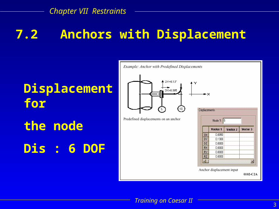
7.2 Anchors with Displacement
Displacement for
the node
Dis : 6 DOF

Training on Caesar II4
Chapter VII Restraints
7.3 Flexible Anchors
Use six flexible restraints
Put :
4 restraints on first element
2 restraints on next element

Training on Caesar II5
Chapter VII Restraints
7.4 Flexible Anchors with Predefined Displacement
Use six flexible restraints
Put :
* 4 restraints on first element
* 2 restraints on next element
* Define connecting node
(Cnode)
* Spec : displacement

Training on Caesar II6
Chapter VII Restraints
Flexible Anchors with Predefined Displacement
Continued...

Training on Caesar II7
Chapter VII Restraints
7.5 Flexible Nozzle (WRC Bulletin 297)
Adhere to these requirements when modeling flexible nozzles:• Frame only one pipe element into the nozzle node.• Do not place restraints at the nozzle node.• Do not place anchors at the nozzle node.• Do not specify displacements for the nozzle node.
CAESAR II automatically performs the following functions:• calculates nozzle flexibilities for the nozzle/vessel data entered by the user• calculates and inserts restraints to simulate the nozzle flexibilities• calculates flexibilities for the axial translations, circumferential, and longitudinalbending

Training on Caesar II8
Chapter VII Restraints
Example :

Training on Caesar II9
Chapter VII Restraints
7.5.1 Flexible Nozzle with Predefined Displacements
Define a unique vessel node on the Nozzle Spreadsheet
Applly the predefined displacement to the vessel node
Training on Caesar II10
Chapter VII Restraints
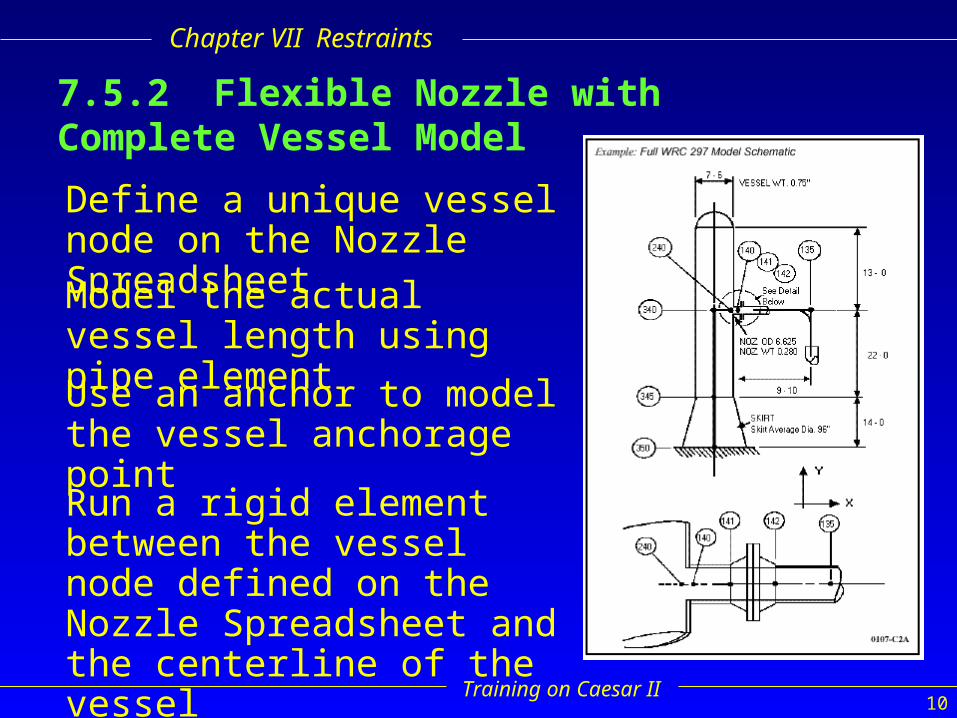
7.5.2 Flexible Nozzle with Complete Vessel Model
Define a unique vessel node on the Nozzle Spreadsheet
Model the actual vessel length using pipe element
Use an anchor to model the vessel anchorage point
Run a rigid element between the vessel node defined on the Nozzle Spreadsheet and the centerline of the vessel
Training on Caesar II11
Chapter VII Restraints
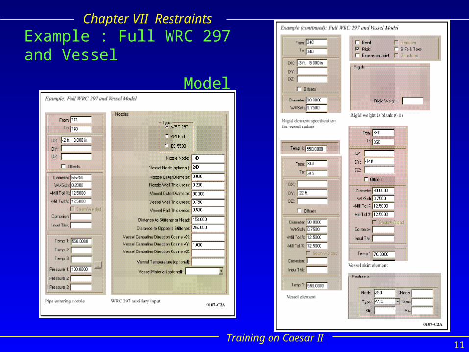
Example : Full WRC 297 and Vessel
Model
Training on Caesar II12
Chapter VII Restraints
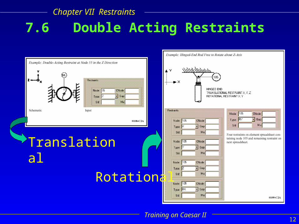
7.6 Double Acting Restraints
Rotational
Translational
Training on Caesar II13
Chapter VII Restraints
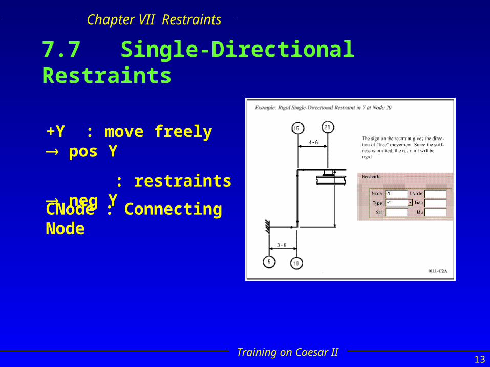
7.7 Single-Directional Restraints
+Y : move freely pos Y
: restraints neg Y
CNode : Connecting Node

Training on Caesar II14
Chapter VII Restraints
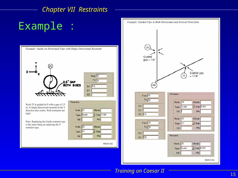
7.8 Guide
• Double-acting restraints with or without a specified gap.
• Connecting Nodes (CNode) can be used with guides.
• May be using the global coordinate or restraints type GUI
• A “guide” pipe in horizontal : acting in the horizontal plane, orthogonal to the axis of pipe
• A “guide” vertical pipe : X and Z direction supports
• Direction cosines : compute by CAESAR II
Training on Caesar II15
Chapter VII Restraints
Example :
Training on Caesar II16
Chapter VII Restraints
7.9 Limit Stops
• Single or double-acting restraint whose line of action is along the axis the pipe
• The sign on the single-directional restraints : unlimited free movement
• The gab is the distance of permitted free movement along the restraints line of action
• Always positive, restraints type : LIM
• Connecting Nodes (Cnode) may be used with any Limit Stop Model

Training on Caesar II17
Chapter VII Restraints
Example :

Training on Caesar II18
Chapter VII Restraints
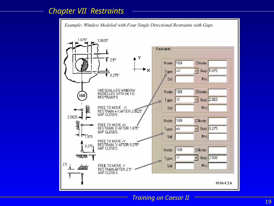
7.10 Windows• Equal leg windows are modeled using two double-acting
restraints with gaps orthogonal to the pipe axis.• Unequal leg windows are modeled using four single-acting
restraints with gaps orthogonal to the pipe axis.• The gap is always positive. If there is no sign, then the
restraint is double-acting and the gap exists on both sides of the line of action of the restraint. If there is a sign on the restraint then the gap exists on the “restrained” line of action of the restraint, i.e. a +Y restraint is restrained against movement in the -Y direction, and any gap associated with a +Y restraint is the free movement in the -Y direction before the restraint begins acting.
Training on Caesar II19
Chapter VII Restraints
Training on Caesar II20
Chapter VII Restraints
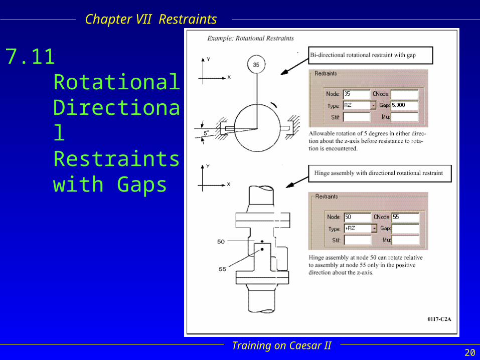
7.11 Rotational Directional Restraints with Gaps

Training on Caesar II21
Chapter VII Restraints
7.12 Single Directional Restraints with Predefined Displacement

Training on Caesar II22
Chapter VII Restraints
7.13 Single-DirectionalRestraint and Guide
Training on Caesar II23
Chapter VII Restraints
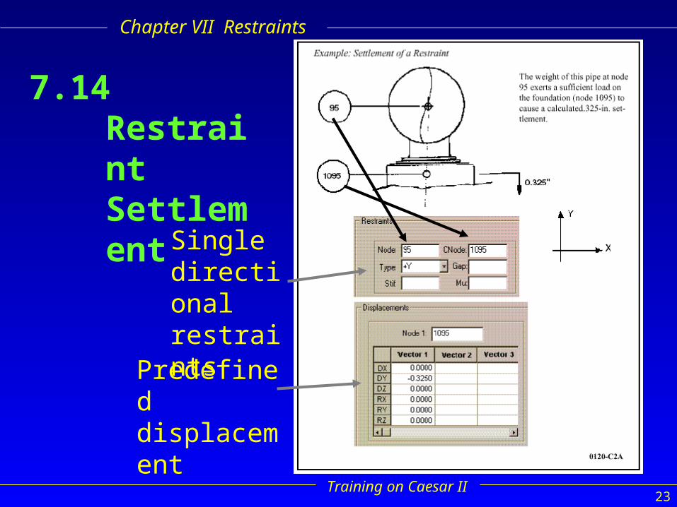
7.14 Restraint Settlement
Single directional restraints
Predefined displacement

Training on Caesar II24
Chapter VII Restraints
7.15 Skewed Double-Acting Restraint

Training on Caesar II25
Chapter VII Restraints
7.16 Skewed Single-Directional Restraint
May be non linear
vector
Direction cosines
A long positive line of action
Connecting Nodes (Cnode) can be used

Training on Caesar II26
Chapter VII Restraints
7.17 Restraint Between Two Pipes
(Use of CNodes)

Training on Caesar II27
Chapter VII Restraints
7.18 Restraint Between Vessel and Pipe Models
CNode connecting pipe to rigid element (vessel shell)
Linear or nonlinear
Training on Caesar II28
Chapter VII Restraints
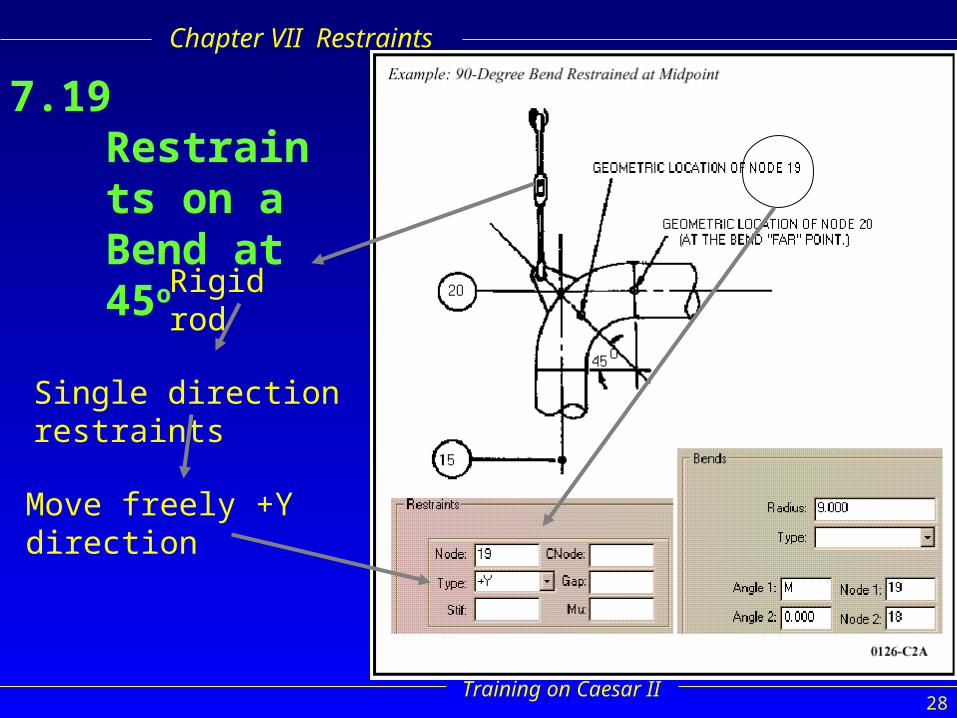
7.19 Restraints on a Bend at 45o
Rigid rod
Single direction restraints
Move freely +Y direction

Training on Caesar II29
Chapter VII Restraints
7.19.1 Restraints on a Bend at 30o
and 60o
3 nodes angle
0o “near” point
To node
“far” point
Training on Caesar II30
Chapter VII Restraints
7.20 Vertical Dummy Leg on Bends
7.20.1 Near/Far Point Method• Easy input• Dummy leg acts along centerline of vertical run• Dummy leg does not act at the proper place on the bend
curvature
7.20.2 On Curvature Method• Easy input• Dummy leg acts at the proper place on the bend curvature• Dummy leg does not act along the centerline of the vertical run
7.20.3 Offset Element Method• Difficult input• Dummy leg acts at the proper place on the bend curvature• Dummy leg acts along centerline of vertical run

Training on Caesar II31
Chapter VII Restraints

Training on Caesar II32
Chapter VII Restraints
7.21 Vertical Leg AttachmentAngle

Training on Caesar II33
Chapter VII Restraints
7.22 Horizontal Dummy Leg on Bends
Dummy leg is defined as a zero-eightrigid supported on oneend by a spring can.

Training on Caesar II34
Chapter VII Restraints
7.23 Large Rotation Rods (Basic Model)
XROD
YROD
ZROD
Gap Len
Mu Fi
Tolerance : 1o
swing : 5o
+Y or Y
concave

Training on Caesar II35
Chapter VII Restraints
7.24 Large Rotation Rods (Chain Supports)
Large rotation swing : chain support (Y-Z plane)
two pipes : move freely relative to each other in the axial direction (Y-X) plane

Training on Caesar II36
Chapter VII Restraints
7.25 Large Rotation Rods
• Stif, Len, Fi : must be filled
• with or without CNode
Spring Hangers
Constant Effort Hangers
Very small
Training on Caesar II37
Chapter VII Restraints
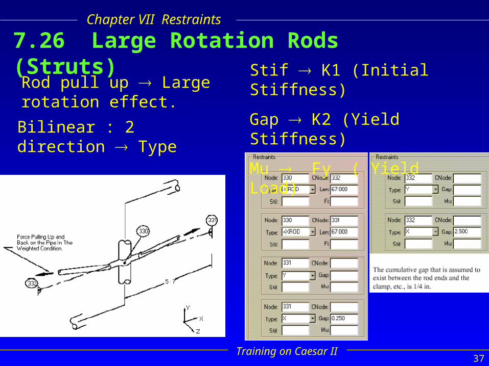
7.26 Large Rotation Rods (Struts)
Rod pull up Large rotation effect.
Bilinear : 2 direction Type
Stif K1 (Initial Stiffness)
Gap K2 (Yield Stiffness)
Mu Fy ( Yield Load)

Training on Caesar II38
Chapter VII Restraints
Continued…

Training on Caesar II39
Chapter VII Restraints
Plastic Hinges
bending
Plastic deformation
Plastic hinge
overheated
Translational
torsional
Bi-linear restraints
Training on Caesar II40
Chapter VII Restraints
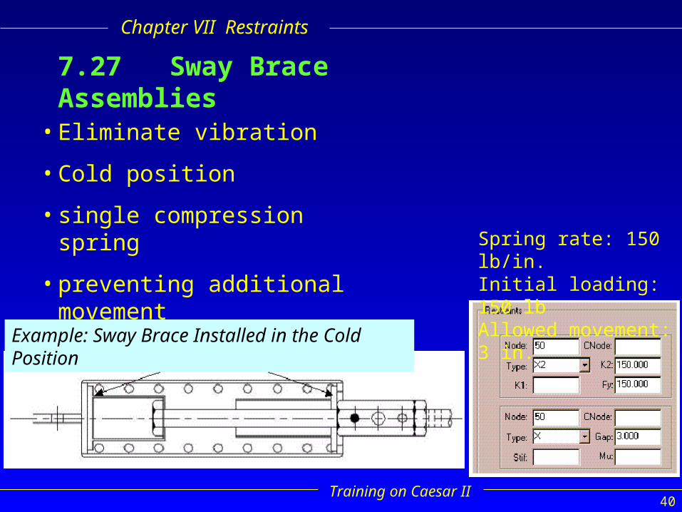
7.27 Sway Brace Assemblies
Example: Sway Brace Installed in the Cold Position
Spring rate: 150 lb/in.Initial loading: 150 lbAllowed movement: 3 in.
• Eliminate vibration
• Cold position
• single compression spring
• preventing additional movement
Training on Caesar II41
Chapter VII Restraints
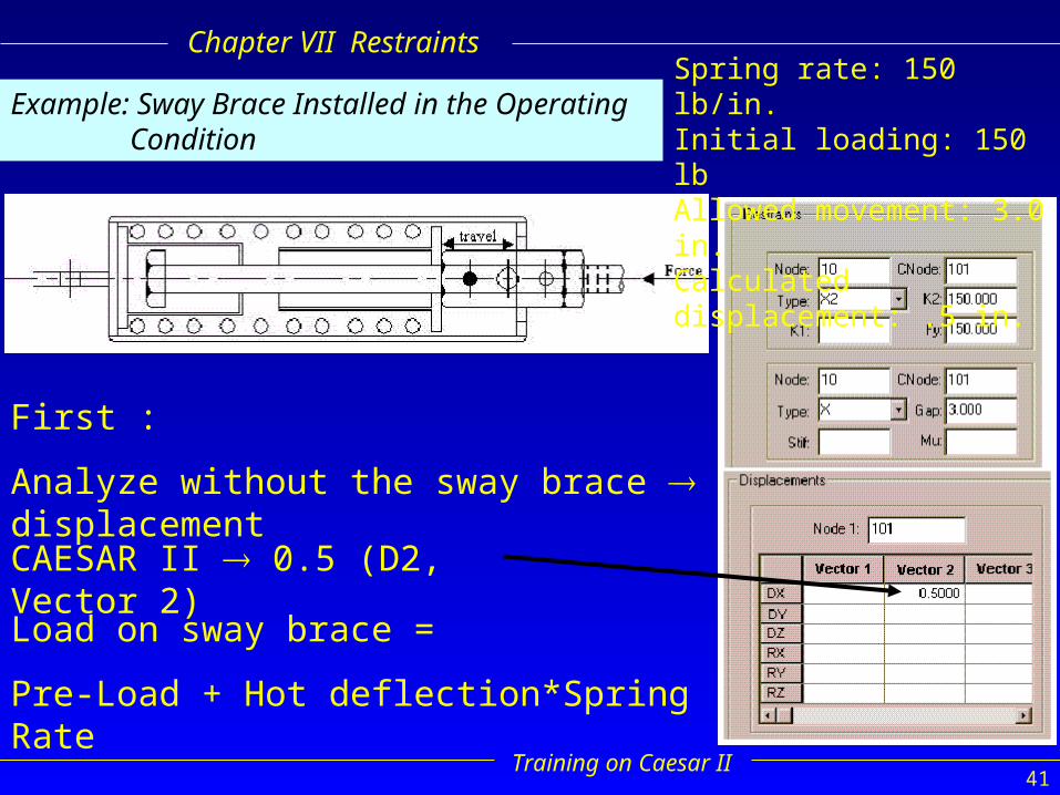
Example: Sway Brace Installed in the Operating Condition
Spring rate: 150 lb/in.Initial loading: 150 lbAllowed movement: 3.0 in.Calculated displacement: .5 in.
First :
Analyze without the sway brace displacement
CAESAR II 0.5 (D2, Vector 2)
Load on sway brace =
Pre-Load + Hot deflection*Spring Rate
Training on Caesar II42
Chapter VII Restraints
END OF RESTRAINTS