bachelor degree project attack modeling and risk ...1346557/fulltext01.pdf · most sdn...
TRANSCRIPT

Author: Tanyi FrankelineSupervisor: Narges KhakpourSemester: VT 2019Subject: Computer Science
Bachelor Degree Project
Attack Modeling and RiskAssessments in Software Definednetworking (SDN)

Abstract
Software Defined Networking (SDN) is a technology which provides a network ar-chitecture with three distinct layers that is, the application layer which is made upof SDN applications, the control layer which is made up of the controller and thedata plane layer which is made up of switches. However, the exits different typesof SDN architectures some of which are interconnected with the physical network.At the core of SDN, the control plane is physically and logically separated from thedata plane. The controller is connected to the application layer through an inter-face known as the northbound interface and to the data plane through another inter-face known as the southbound interface. The centralized control plane uses APIs tocommunicate through the northbound and southbound interface with the applicationlayer and the data plane layer respectively. By default, these APIs such as Restfuland OpenFlow APIs do not implement security mechanisms like data encryption andauthentication thus, this introduces new network security threats to the SDN architec-ture. This report presents a technique known as threat modeling in SDN. To achievethis technique, attack scenarios are created based on the OpenFlow SDN vulnerabil-ities. After which these vulnerabilities are defined as predicates or facts and rules,a framework known as multihost multistage vulnerability analysis (MulVAL) thentakes these predicates and rules to produce a threat model known as attack graph.The attack graph is further used to performed quantitative risk analysis using a met-ric to depict the risks associated to the OpenFlow SDN model
Keywords: SDN, Application layer, Northbound Interface, Controller, South-bound Interface, data plane OpenFlow, Threat Model, MulVAL, Attack Graph,Attack Trees, Risk Analysis

Preface
I want to use this opportunity to say a very big thank you to both my supervisor NargesKhakpour and co-supervisor Charilaos Skandylas for the wonderful guidelines andsupport they gave me throughout this project
Contents
1 Introduction 11.1 Background . . . . . . . . . . . . . . . . . . . . . . . . . . . . . . . . . 11.2 Problem formulation . . . . . . . . . . . . . . . . . . . . . . . . . . . . 21.3 Motivation . . . . . . . . . . . . . . . . . . . . . . . . . . . . . . . . . . 21.4 Objectives . . . . . . . . . . . . . . . . . . . . . . . . . . . . . . . . . . 31.5 Scope/Limitation . . . . . . . . . . . . . . . . . . . . . . . . . . . . . . 31.6 Target group . . . . . . . . . . . . . . . . . . . . . . . . . . . . . . . . . 31.7 Outline . . . . . . . . . . . . . . . . . . . . . . . . . . . . . . . . . . . 3
2 Background 52.1 Architecture of Software Defined Networking (SDN) . . . . . . . . . . . 5
2.1.1 Application Layer . . . . . . . . . . . . . . . . . . . . . . . . . 52.1.2 Northbound Interface (NBI) . . . . . . . . . . . . . . . . . . . . 62.1.3 Control Layer . . . . . . . . . . . . . . . . . . . . . . . . . . . . 62.1.4 Southbound Interface (SBI) . . . . . . . . . . . . . . . . . . . . 62.1.5 Data plane or Forwarding plane . . . . . . . . . . . . . . . . . . 62.1.6 Management Plane . . . . . . . . . . . . . . . . . . . . . . . . . 7
2.2 SDN Models . . . . . . . . . . . . . . . . . . . . . . . . . . . . . . . . 72.2.1 Hybrid SDN Model . . . . . . . . . . . . . . . . . . . . . . . . . 72.2.2 Overlay SDN Model . . . . . . . . . . . . . . . . . . . . . . . . 82.2.3 OpenFlow SDN Model . . . . . . . . . . . . . . . . . . . . . . . 8
2.3 SDN Vulnerability . . . . . . . . . . . . . . . . . . . . . . . . . . . . . 122.3.1 Application Layer . . . . . . . . . . . . . . . . . . . . . . . . . 122.3.2 Control Layer . . . . . . . . . . . . . . . . . . . . . . . . . . . . 132.3.3 Data Plane Layer . . . . . . . . . . . . . . . . . . . . . . . . . . 142.3.4 SDN Protocol . . . . . . . . . . . . . . . . . . . . . . . . . . . . 14
2.4 Threat Models . . . . . . . . . . . . . . . . . . . . . . . . . . . . . . . . 152.4.1 Attack Trees . . . . . . . . . . . . . . . . . . . . . . . . . . . . 162.4.2 Attack Graphs . . . . . . . . . . . . . . . . . . . . . . . . . . . 17
2.5 Risk Analysis/Assessment . . . . . . . . . . . . . . . . . . . . . . . . . 182.6 Multihost, multistage Vulnerability Analysis (MulVAL) . . . . . . . . . . 192.7 Related work . . . . . . . . . . . . . . . . . . . . . . . . . . . . . . . . 20
3 Method 223.1 Scientific approach . . . . . . . . . . . . . . . . . . . . . . . . . . . . . 223.2 Method description . . . . . . . . . . . . . . . . . . . . . . . . . . . . . 223.3 Attack Scenarios . . . . . . . . . . . . . . . . . . . . . . . . . . . . . . 23
3.3.1 Before attack on the SDN Controller with a malicious application 233.3.2 Attack on the SDN controller with a malicious application . . . . 243.3.3 Before attack on Link Layer Discovery Protocol (LLDP) . . . . . 253.3.4 Attack on Link Layer Discovery Protocol . . . . . . . . . . . . . 263.3.5 Before Man-in-the-middle attack on OpenFlow Switches . . . . . 273.3.6 Man-in-the-middle attack on OpenFlow Switches . . . . . . . . . 283.3.7 Attack on flooding the OpenFlow switch and the controller . . . . 29
3.4 Attack Modeling . . . . . . . . . . . . . . . . . . . . . . . . . . . . . . 293.4.1 Rules for attack on controller with a malicious application . . . . 303.4.2 Rules for attack on Link Layer Discovery Protocol . . . . . . . . 333.4.3 Rules for Man-in-the-middle attack on OpenFlow switch . . . . . 34

3.4.4 Rules for attack on flooding the switch and the controller . . . . . 363.4.5 Combining Attacks . . . . . . . . . . . . . . . . . . . . . . . . . 37
3.5 Reliability and Validity . . . . . . . . . . . . . . . . . . . . . . . . . . . 393.6 Ethical considerations . . . . . . . . . . . . . . . . . . . . . . . . . . . . 39
4 Implementation and Evaluation 404.1 Results . . . . . . . . . . . . . . . . . . . . . . . . . . . . . . . . . . . . 41
4.1.1 Results from Attack on the controller with a malicious application 414.1.2 Results from attack on Link Layer Discovery protocol . . . . . . 434.1.3 Results from man-in-the-middle-attack on the data plane . . . . . 454.1.4 Results from attack on flooding the switch and the controller . . . 474.1.5 Overall analysis with a Metric . . . . . . . . . . . . . . . . . . . 48
5 Discussion and Conclusion 515.1 Future work . . . . . . . . . . . . . . . . . . . . . . . . . . . . . . . . . 53
References 54
A Appendix 1 A

1 Introduction
Software Defined Networking (SDN) is an emerging network technology where the con-trol plane is logically and physically decoupled from the forwarding plane which is pro-grammable [1]. SDN provides network operators with a more efficient network man-agement and deployment of new services to run their infrastructures while enabling keyfeatures such as virtualization [2]. The network intelligence of software defined network-ing is logically centralized in a software-based SDN controller, which maintains a globalview of the network. Such that, the network appears to the applications and policy enginesas a single logical switch. SDN simplifies the network devices themselves, since they nolonger need to understand and process thousands of protocol standards but merely acceptinstructions from the SDN controller [3]. SDN also provides the possibility for innovatingnew network applications. These applications can be written to support traffic manage-ment, energy-efficiency or security in the network. In order to support these applications,current network state information is required. The SDN controller alters how the networkstate information is being maintained and made available to applications and switches [4].
An SDN model is a technique used to abstract lower level functions of networks intoa control plane allowing administrators to direct traffic flows from a centralized console[5]. There are three types of SDN models the switch-based model also known as theOpenFlow model which provides a central control point to instruct switches on how toprocess network traffic. The hybrid model which is a combination of two or more net-working technologies in a single environment that is, the control plane can be configuredto manage specific network traffic while the traditional networking protocols can manageother network traffic and the overlay model which act as a tunnel through the physicalnetwork to run multiple virtual network topologies [6].
MulVAL (Multihost, multistage Vulnerability Analysis) is a framework for modelingsoftware vulnerabilities with systems and configurations. The inputs to MulVAL’s anal-ysis are advisories which are used to produce threat models [7]. Datalog is a declarativelogic programming language that is syntactically a subset of Prolog. It is often used asa query language for deductive databases. In recent years, Datalog has found new appli-cation in data integration, information extraction, networking, program analysis, security,and cloud computing [8].
A threat refers to anything that has the potential to cause harm or danger to the securityof one or more asserts or components. Threats can be malicious from insider or outsider,accidental due to mismanagement of asserts and from natural events. That is, a threatmay or may not happen but has the potential to cause serious harm to a system leading toattacks [9]. Some examples of threat models are attack graphs and attack trees. Further-more, a threat model is also a technique used to specify and analyze system vulnerabilitiesand/or countermeasures that are provided with methods for security risk assessment andthreat/defense prioritization. A threat model helps an architecture to determine the attacksurface, assign risks to each threat and drive a vulnerability mitigation process [10].
1.1 Background
A typical SDN architecture consists of three layers. The Application layer which is madeup of network applications or functions and intrusion detection systems. The control layerwhich represents a centralized SDN controller software acting as the brain of SDN andlastly the Infrastructure or data plane layer which consists of forwarding devices suchas switches. The aim of SDN is to make networks agile and flexible by physically andlogically separating the network control plane from the forwarding or data plane [11].
1

The application layer communicates with the controller through the northbound interfacewhich consist of Restful APIs that uses HTTP protocol requests to GET, PUT, POST andDELETE data. The current implementations of these interfaces have several drawbackson the SDN architecture that is, such critical interfaces do not offer security featuresrequired to monitor and enforce access control of SDN applications thus, the absence ofthese security features by default allows all SDN applications to have full access to theunderlying network enabling the possibility for potential malicious applications [12].
OpenFlow switches uses the OpenFlow protocol to communicates with the controllerthrough the southbound interface [9]. OpenFlow does not enforce the use of secure com-munication channel between the switches and the controller. That is, the implementationof Transport Layer Security (TLS) is optional. Due to the evolving nature of OpenFlowprotocol, many vendors do not implement any security mechanisms.
The lack of adopting and problems with the implementation of security mechanismssuch as TLS, most infrastructures leave a clear path for attackers to infiltrate OpenFlownetworks using possible attacks and to make things worse, there is no authentication noraccess control mechanisms [13].
1.2 Problem formulation
The centralized SDN controller presents a single point of failure and if targeted by an at-tacker, can prove detrimental to the network. Decoupling or separating the control planefrom the data plane by SDN also exposes new threats that do not appear in the tradi-tional IP network such as MAC flooding, spoofing, denial of service attack (DoS/DDoS),rogue controllers and rogue switches [14], [15], [16]. One possible threat to the SDNarchitecture is man-in-the-middle attack [1].
The aim of this project is to investigate the security of OpenFlow SDN model andits vulnerabilities and further investigate different threat models such as attack graphs andattack trees. Design some attacks scenarios associated to these vulnerabilities and formal-ized them into Datalog facts and rules using a framework known as MulVAL to generatean attack graph. Then analyze the attack graph to depict possible intrusions and/or attacksby an attacker on the OpenFlow SDN network and the risks associated to the possible in-trusions and/or attacks. Thus, the end-product of this project is an attack graph derivedfrom the OpenFlow SDN model and the risk analysis associated to the attack graph. Basedon the outcome of the risk analysis, the risk of vulnerabilities associated to the OpenFlowSDN model is deduced. In addition, the attack graph also gives a better understanding ofattack pattern such as from an attacker entry point into the SDN network to its maliciousgoal. With this information, a better risk analysis and assessment can be done since thepaths taken by an attacker to reach its malicious goal is known.
1.3 Motivation
Most SDN architectures implements Intrusion detection systems (IDS) to detect possibleintrusions or attacks into systems rather than using threat models such as attack graphs[17]. The IDS operate in two modes, On-path detection which is placed on packets routeto analyze every packet before forwarding the packets and Off-path detection where theIDS is a separate node on the network connected to a switch and every packet that arrivesin the switch is mirrored to the port in which the IDS is connected [17]. An example is useof Future Internet Testbed with Security (FITS) to provide a virtual environment wherethe SDN controller is configured to install rules that sends packets both to their destinationand to the IDS. When an IDS identifies a malicious flow, it generates an alarm and sent it
2

to the controller. The controller then lists all the flows installed in the OpenFlow switchesand set a drop action to all the flows that matches the malicious flows [18].
However, threat models such as attack graphs and attack trees can be used to deducepossible ways an attacker or malicious flows can penetrate a system and assign probabili-ties to each path according to some metric such as time-to-compromise. Thus, the attackgraph derived from the OpenFlow SDN model is deemed appropriate enough to identifypossible threats associated to the SDN model.
1.4 Objectives
O1 Investigate the security of OpenFlow SDN model and its componentsO2 Investigate threat models known as attack graphs and attack treesO3 Derive a threat model from the OpenFlow SDN model which is an
attack graphO4 Perform risk analysis on the OpenFlow SDN model using the derived
threat model by quantitative analysis.
1.5 Scope/Limitation
For this project, we investigated the different SDN models and their vulnerabilities. How-ever, the scope of this project is limited to the OpenFlow SDN based model and its vul-nerabilities. Thus, the threat model generated by MulVAL for this project and the riskanalysis is based solely on the OpenFlow SDN model.
1.6 Target group
The target group for this project includes computer science students, network adminis-trators, network engineers, network security personnel, software engineers, people con-cerned about the state of modern security and data centers who are the major end usersof the SDN framework due to the increased adoption of SDN in the evolving software-defined data center. A modern data center networking leverages the SDN framework toaccommodate multiple data center tenants with demanding workloads and applications.The aim of this project is to offer a good insight about threats models such as attack graphsto deduce the possible attacks on the OpenFlow based software defined networking archi-tecture.
1.7 Outline
This report is organized into five chapters. Chapter 1 which is the current chapter intro-duces the background and the problem to be solve. Chapter 2 presents a broad backgroundof the project, chapter 3 describes the method used to solve the problem, chapter 4 de-scribes the implementation and the results realized from solving the problem and finallychapter 5 discuss the problem, results and draw a conclusion.
Chapter 1 – Here we introduce this project with a brief overview of the background. Theproblem formulation, motivation, objectives needed to achieve the aim of this project, thescope and the target group for this project.
Chapter 2 – Background. This chapter presents the literature review of the SDN archi-tecture and OpenFlow vulnerabilities. Threat models for systematic detection of attacks,
3
risk analysis and a framework used for attack modeling known as MulVAL.
Chapter 3 – Method. This chapter describes the scientific approach used to archive theobjectives. This includes how the literature review of SDN architecture and its vulnerabil-ities were done and formal threat/attack scenario modeling using the MulVAL framework.
Chapter 4 – Implementation and Results. This chapter describes the method used toachieve the objectives of this project with the aid of a flowchart, implementation envi-ronment, the results of the implementation and analysis of the results.
Chapter 5 – Discussion and Conclusion. In this chapter, I discuss my findings, com-pare it with other methods and draw a conclusion by proposing my project for any SDNsecurity related projects.
4

2 Background
This chapter presents information about the SDN architecture, SDN models, SDN vulner-abilities and threat models needed to achieve the goals of this project.
2.1 Architecture of Software Defined Networking (SDN)
As mentioned in the previous chapter, software defined networking is made up of threedistinct layers that is, the application layer, the control layer and the data plane layer.These layers are further separated by the northbound and southbound interface as shownon Figure 2.1. The aim of this project is to investigate the vulnerabilities of software de-
Figure 2.1: SDN architecture
fined networking. However, to look for these vulnerabilities, the SDN architecture mustbe understood to a certain extent to be able to identify these vulnerabilities. As shownon Figure 2.1 above, the application layer communicates with the controller through thenorthbound interface. The northbound interface is made up of controller-to-applicationAPIs that uses the HTTP protocol. SDN applications uses the HTTP POST request tomodify the state of switches, GET request to query information about the network stateand configurations from the controller and the Delete request to delete network config-urations. The data plane which consists of switches uses the southbound interface tocommunicates with the controller. The southbound interface is made up of different APIsdepending on the type of SDN model such as OpenFlow which will be discussed in thenext section.
2.1.1 Application Layer
This layer is made up of SDN applications such as network policy, routing, monitor-ing, ARP, firewalls. These applications are programs that are explicitly and directly pro-grammable. These applications communicate their requirements to the SDN controllerthrough the northbound interface. They contribute in decision making of the entire net-work. SDN applications consists of one SDN application Logic and one or more north-bound interface Drivers [3].
5
2.1.2 Northbound Interface (NBI)
The NBI is made up of Restful APIs and there is no standard controller-to-applicationnorthbound interface framework that is, each framework may establish different bound-aries between the core functionalities and extensible applications. Applications can bedeployed in two ways that is, as an internal module within the controller or separatelyas an external module separated from the controller. For example, Open Network Oper-ating System (ONOS) uses the Open Services Gateway Initiative (OSGi) framework inJava to manage the internal application module and states while Open-daylight (ODL)and Floodlight, uses the Restful API for external applications [19].
2.1.3 Control Layer
This layer is made up of the controller which serves as a central repository for controlinstructions such as data flow logic, security policies and business policies required to de-ploy, configure and manage network elements such that, they obtain an optimal and desirenetwork behavior. The controller provides a programmatic interface for the provisioningof network services [20]. The controller also uses open or proprietary protocol to controleach network element and traffic flow on the network by modifying the flow tables oneach switch in a proactive or re-active manner [21].
SDN relies heavily on control messages between the controller and the forwardingdevices for reliable network operation. The controller extracts information about the stateof network elements and forward or process the information to SDN applications with anabstract view of the network and statistics events about the state of network [20].
2.1.4 Southbound Interface (SBI)
This interface consists of southbound APIs that enables the SDN controller to dynam-ically communicates with the data plane components using messages. The southboundAPI messages can be of two types that is, these messages can either be control planeor management plane traffic. This interface also provides the mechanisms used by thecontroller to send forwarding rules through the control plane messages to the networkswitches in order to keep their flow tables updated.
Furthermore, it also allows the controller to send management plane traffic to provi-sion and configure network elements. This API also provide a means to keep the controllerupdated with information about the state of network elements. This information includesthe concept of flows to identify network traffic based on predefined match rules that can bestatically or dynamically programmed by the SDN controller. The controller also defineshow traffic should flow through network elements based on policy, usage, applications,and available bandwidth [20].
2.1.5 Data plane or Forwarding plane
The data plane consists of network forwarding elements known as switches. Their mainobjectives are to forward incoming network traffic flows to their destinations making useof routes defined in their flow tables by the controller [22]. The data plane also sep-arates information received by switches from information required to process the data.In software defined networking (SDN), the data plane is software rather than firmware.Decoupling the data plane from the control plane allow greater flexibility and dynamiccontrol of the network states [23].
6
2.1.6 Management Plane
The management plane is an abstract additional centralized plane to the SDN architecturewhich can be managed by the network administrator with the aim to ensure the networkconfiguration is done properly and the whole network is running optimally by commu-nicating with the network devices. A management plane is connected to the SDN archi-tecture through the Southbound Interface (MPSI). The management plane functionality isinitiated based on an overall view of the network and are of human-control such as fault,monitoring and configurations [24].
2.2 SDN Models
This section presents the different software defined networking models that was intro-duced in the previous chapter that is, the OpenFlow, Hybrid and the Overlay SDN model.
2.2.1 Hybrid SDN Model
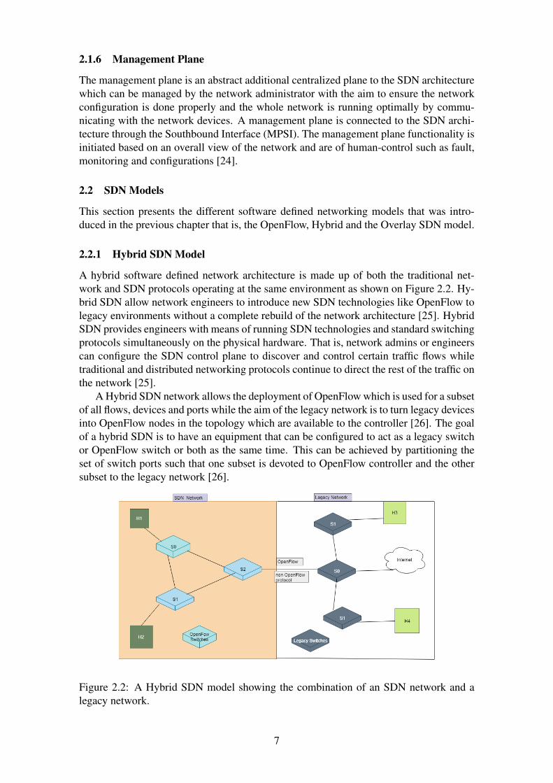
A hybrid software defined network architecture is made up of both the traditional net-work and SDN protocols operating at the same environment as shown on Figure 2.2. Hy-brid SDN allow network engineers to introduce new SDN technologies like OpenFlow tolegacy environments without a complete rebuild of the network architecture [25]. HybridSDN provides engineers with means of running SDN technologies and standard switchingprotocols simultaneously on the physical hardware. That is, network admins or engineerscan configure the SDN control plane to discover and control certain traffic flows whiletraditional and distributed networking protocols continue to direct the rest of the traffic onthe network [25].
A Hybrid SDN network allows the deployment of OpenFlow which is used for a subsetof all flows, devices and ports while the aim of the legacy network is to turn legacy devicesinto OpenFlow nodes in the topology which are available to the controller [26]. The goalof a hybrid SDN is to have an equipment that can be configured to act as a legacy switchor OpenFlow switch or both as the same time. This can be achieved by partitioning theset of switch ports such that one subset is devoted to OpenFlow controller and the othersubset to the legacy network [26].
Figure 2.2: A Hybrid SDN model showing the combination of an SDN network and alegacy network.
7

2.2.2 Overlay SDN Model
An overlay software defined network (SDN) is a technology that creates a layer of ab-straction used to run multiple separate and discrete virtualized network layers on top of aphysical network to provide new applications and additional security benefits. SDN over-lay can be created by using endpoints such as actual physical locations, network ports orlogical locations designated by a software address in the networking cloud [27].
SDN overlay are also used to achieve network visualization by establishing tunnelsbetween severs, switches and gateways where end stations are connected. These tunnelscan be implemented by encapsulating packets transmitted by a source end station into anoverlay header that transport the packet from the source to the target switches using UserDatagram Protocol (UDP) through an internet protocol (IP) [28].
Figure 2.3: Overlay SDN architecture [28].
2.2.3 OpenFlow SDN Model
OpenFlow is considered as the most common deployed software defined networking ar-chitecture. This model consists of mainly three network layers that is, the applicationlayer, control layer and the data plane layer. As mentioned in the previous sections, thecontroller is responsible for managing the forwarding information of the data plane com-ponents or switches [29]. In this model, the OpenFlow protocol provides the interfacedefine by an API for the controller program to interact with the underlying data planeswitches in order to enable seamless communication between the control layer and thedata plane layer [30]. The control layer consists of an operating system that is used tomanage applications and core network services such as routing, monitoring and networkdiscovery [31]. Any switch that uses the OpenFlow protocol can be managed by the SDN
8
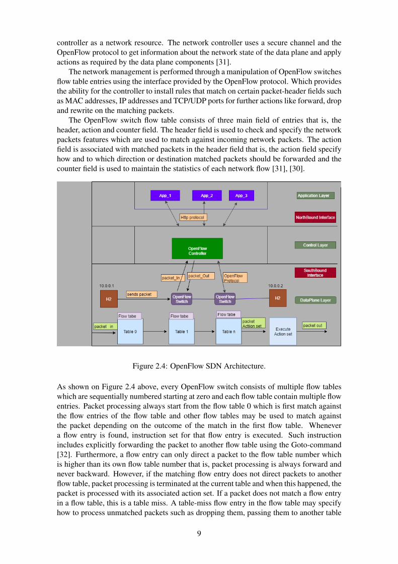
controller as a network resource. The network controller uses a secure channel and theOpenFlow protocol to get information about the network state of the data plane and applyactions as required by the data plane components [31].
The network management is performed through a manipulation of OpenFlow switchesflow table entries using the interface provided by the OpenFlow protocol. Which providesthe ability for the controller to install rules that match on certain packet-header fields suchas MAC addresses, IP addresses and TCP/UDP ports for further actions like forward, dropand rewrite on the matching packets.
The OpenFlow switch flow table consists of three main field of entries that is, theheader, action and counter field. The header field is used to check and specify the networkpackets features which are used to match against incoming network packets. The actionfield is associated with matched packets in the header field that is, the action field specifyhow and to which direction or destination matched packets should be forwarded and thecounter field is used to maintain the statistics of each network flow [31], [30].
Figure 2.4: OpenFlow SDN Architecture.
As shown on Figure 2.4 above, every OpenFlow switch consists of multiple flow tableswhich are sequentially numbered starting at zero and each flow table contain multiple flowentries. Packet processing always start from the flow table 0 which is first match againstthe flow entries of the flow table and other flow tables may be used to match againstthe packet depending on the outcome of the match in the first flow table. Whenevera flow entry is found, instruction set for that flow entry is executed. Such instructionincludes explicitly forwarding the packet to another flow table using the Goto-command[32]. Furthermore, a flow entry can only direct a packet to the flow table number whichis higher than its own flow table number that is, packet processing is always forward andnever backward. However, if the matching flow entry does not direct packets to anotherflow table, packet processing is terminated at the current table and when this happened, thepacket is processed with its associated action set. If a packet does not match a flow entryin a flow table, this is a table miss. A table-miss flow entry in the flow table may specifyhow to process unmatched packets such as dropping them, passing them to another table
9

or sending them to the controller over the control channel through packet-In messages[32].
OpenFlow ports provide a network interface used for processing packets betweenOpenFlow switches and the rest of the network. OpenFlow switches are logically con-nected using these ports. There are several types of OpenFlow ports however, the twomost commonly known and used ports by OpenFlow switches are, the ingress or inputport used to receive, processed and matched packets and the egress or output port used toforward the processed or matched packets to their destination [33].
OpenFlow channel is the southbound interface which connects the controller to theOpenFlow switches. The controller uses this channel or interface to configure, managethe switches, receive events from them and send packet-Out massages to them. This chan-nel is usually encrypted using TLS but may run directly over TCP [33].
i) Controller-To-Switch OpenFlow Messages
• Features: The controller uses this message to get basic switch capabilities by send-ing a Feature-request to the switch over a TCP connection. The switch replies thecontroller with its capabilities by sending back a Feature-respond. The feature re-quest consists of just an OpenFlow header message with the FeatureReq value setin the type field.
• Configuration: The controller can set and query configuration parameters in theswitch using the SetConfig and GetConfigReq messages respectively. These mes-sages can only be initiated by the controller and can be used to determined howmuch packets are needed to be share with the controller.
• Modify-State: This is one of the main messages that are sent by the controller tomanage state on the switches. Their primary purpose is to add, delete and modifyflow entries in the OpenFlow switch flow tables and to set switch port propertiesusing the Flow-Mod and Port-MoD messages respectively.
• Packet-Out: This message is sent by the controller to a specific port on the switchincluding instructions on how to forward the packet received through the packet-Inmessage from the switch. The packet-Out message contains a buffer ID referencinga packet store in the switch buffer and a list of actions.
• Asynchronous-Configuration: The Asynchronous-Configuration message are usedby the controller to set an additional filter on the asynchronous messages receivedon its OpenFlow channel. This is mostly useful when the switch connects to mul-tiple controllers and commonly performed upon establishment of the OpenFlowchannel.
ii) Asynchronous MessageAsynchronous messages are sent without the controller soliciting them from a switch.Switches send asynchronous messages to controllers to denote a packet arrival, switchstate change, or error. The four main types of asynchronous messages are describedbelow.
• Packet-In: This message is used to forward packets to the controller wheneverthere are no match rules in the flow table for incoming packets. Other processing,such as Time-To-Live checking, may also generate packet-In events to send packetsto the controller. Packet-In events can be configured to buffer packets in order tocreate more space in the switch memory.
10

• Flow-Removed: This message is used by the switch to inform the controller aboutthe removal of a flow entry from a flow table and they are only sent for flow entrieswith the OFPFF-SEND-FLOW-REM flag set. They are generated whenever thetimeout for a flow expires or as a result of a controller flow delete request.
• Port-Status: This message is used by the switch to inform the controller about thechange of states of ports. The switch sends the port-status messages to controllersas port configuration or port state changes. These events include changes in portconfiguration events, such as link down or link up.
iii) SymmetricSymmetric messages are messages that can be sent from either direction that is, from thecontroller-to-switch or from-switch-to-controller.
• Hello: The hello massage is used either by the controller or switch during connec-tion setup for version negation. When the connection is established, each side mustimmediately send a Hello message with the version field set to the highest versionsupported by the sender. If the version negotiation fails, an Error message is sentwith type Hello-Failed and code Incompatible.
• Echo: Echo request messages can also be sent from either the switch or the con-troller and must return an echo reply. They are mainly used to verify the livenessof a controller-switch connection and may as well be used to measure its latency orbandwidth [33] [34].
. iv) Basic OpenFlow SDN Functionality
Figure 2.5: A flow graph of basic OpenFlow functionality
Figure 2.4 shows the entire OpenFlow architecture where H1 and H2 are network hosts.H1 sends a packet to H2 through two OpenFlow switches. Based on the flow graph on
11
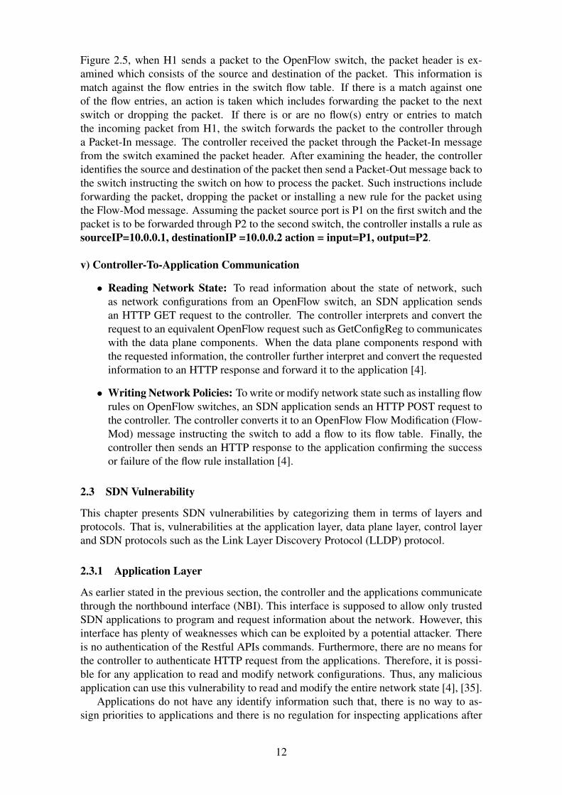
Figure 2.5, when H1 sends a packet to the OpenFlow switch, the packet header is ex-amined which consists of the source and destination of the packet. This information ismatch against the flow entries in the switch flow table. If there is a match against oneof the flow entries, an action is taken which includes forwarding the packet to the nextswitch or dropping the packet. If there is or are no flow(s) entry or entries to matchthe incoming packet from H1, the switch forwards the packet to the controller througha Packet-In message. The controller received the packet through the Packet-In messagefrom the switch examined the packet header. After examining the header, the controlleridentifies the source and destination of the packet then send a Packet-Out message back tothe switch instructing the switch on how to process the packet. Such instructions includeforwarding the packet, dropping the packet or installing a new rule for the packet usingthe Flow-Mod message. Assuming the packet source port is P1 on the first switch and thepacket is to be forwarded through P2 to the second switch, the controller installs a rule assourceIP=10.0.0.1, destinationIP =10.0.0.2 action = input=P1, output=P2.
v) Controller-To-Application Communication
• Reading Network State: To read information about the state of network, suchas network configurations from an OpenFlow switch, an SDN application sendsan HTTP GET request to the controller. The controller interprets and convert therequest to an equivalent OpenFlow request such as GetConfigReg to communicateswith the data plane components. When the data plane components respond withthe requested information, the controller further interpret and convert the requestedinformation to an HTTP response and forward it to the application [4].
• Writing Network Policies: To write or modify network state such as installing flowrules on OpenFlow switches, an SDN application sends an HTTP POST request tothe controller. The controller converts it to an OpenFlow Flow Modification (Flow-Mod) message instructing the switch to add a flow to its flow table. Finally, thecontroller then sends an HTTP response to the application confirming the successor failure of the flow rule installation [4].
2.3 SDN Vulnerability
This chapter presents SDN vulnerabilities by categorizing them in terms of layers andprotocols. That is, vulnerabilities at the application layer, data plane layer, control layerand SDN protocols such as the Link Layer Discovery Protocol (LLDP) protocol.
2.3.1 Application Layer
As earlier stated in the previous section, the controller and the applications communicatethrough the northbound interface (NBI). This interface is supposed to allow only trustedSDN applications to program and request information about the network. However, thisinterface has plenty of weaknesses which can be exploited by a potential attacker. Thereis no authentication of the Restful APIs commands. Furthermore, there are no means forthe controller to authenticate HTTP request from the applications. Therefore, it is possi-ble for any application to read and modify network configurations. Thus, any maliciousapplication can use this vulnerability to read and modify the entire network state [4], [35].
Applications do not have any identify information such that, there is no way to as-sign priorities to applications and there is no regulation for inspecting applications after
12
they are installed thus, it is possible for legitimate applications to become malicious afterinstallation [4], [36]. Furthermore, the ability for applications to access and modify thecontrol plane state information which consists of data store and control plane messagescreates a share state design among applications thereby creating an attack vector for in-tegrity attacks whereby a trusted application may unintentionally use data generated byuntrusted applications [19]. These vulnerabilities possess several attack vectors such as:
• Inferring information in the data plane: That is, a malicious application can con-trol the data plane by manipulating OpenFlow messages such as sniffing networkpackets and rerouting network traffic with forge flow entries on the switches.
• Intrusion into the Controller: Malicious applications can get network operationsthrough a direct access to the network resources in the SDN controller by the ex-ploiting the northbound API to reorder a network service chain, poison the topologyand fabricate the statistics of network traffic [35].
• Attack on SDN Applications: A malicious SDN application can uninstall usingthe Uninstall-Function or run other SDN applications such as firewalls and Intrusiondetection systems thereby allowing the attacker to bypass existing defense mecha-nisms [35].
• Information Leakage: A malicious application can leak vital information of thenetwork to an attacker by obtaining the controller configurations, network state andflow tables entries which can be used to perform future attacks.
2.3.2 Control Layer
OpenFlow switches do not have physical MAC addresses as physical switches but ratherthey have Data-Path-Id which is used to identify them [37]. On this note, it is possible toperform attacks using the lower level protocols to create denial of service attacks. That is,assuming two switches have the same data-path-id whereby one is malicious and the otheris legitimate. The legitimate switch connects to the controller first and maintain a TCPsession. When the malicious switch connects to the controller, the controller terminatesthe connection with the legitimate switch and then established a new connection with themalicious switch and if the legitimate switch tries to re-establish another connection tothe controller, the malicious switch also re-establishes another connection which effec-tively denies the connection between the legitimate switch and the controller. Therebygradually degrading network performance as cached entries in the legitimate switch flowtable expires [38].
The SDN controller and its network applications maintain a list of network configura-tions such as host profile, switch liveness and link status. By having a proper reference ofthe network state, the controller can enforce network policies such as network monitoring,routing and flow balancing. However, referencing network states is under the risk of in-troducing concurrent vulnerabilities because the external network events can concurrentlyupdate the internal network states [39]. These concurrent vulnerabilities can be used toperformed state manipulation attacks in the controller using a-synchronism to cause harm-ful race conditions on the share network states. This can be exploited by an attacker tocause denial of service on the controller. By exploiting harmful race conditions, the at-tacker can inject control plane messages such as HOST-LEAVE and SWITCH-LEAVEto modify the internal state of the SDN controller [39]. The integration of core con-troller functions creates an initial setup for the SDN network. For example, the topology
13

manager stores information regarding devices such as switches and hosts in the networkand uses the Link Layer Discovery Protocol (LLDP) to discover the interconnected linksbetween the OpenFlow switches. An attacker can exploit vulnerabilities using a mali-cious module inside the SDN controller to poison the topology, create fake links betweenswitches with the LLDP protocol which affect the functionality of the entire network [40].
2.3.3 Data Plane Layer
As stated in the previous section, the OpenFlow protocol defines the communication be-tween the controller and the data plane devices known as OpenFlow switches. The com-munication between the controller and the OpenFlow switches can be either encryptedwith TLS or in plain text. OpenFlow specification does not mandate TLS support andin some cases OpenFlow switches do not support TLS [41]. Therefore, decision-makingprocess and distribution of policy enforcement to the data plane introduces new problemwith regards to information disclosure. Thus, it is possible for an attacker to perform sidechannel attacks on OpenFlow switches where the attacker can gather relevant informa-tion about the behavior and network configuration of switches. A flow table side-channelis defined as a means by which an attacker can learn or infer the flow table contents ofswitches [41].
Detail description on how an attacker can access OpenFlow switches to perform a sidechannel attack is out of the scope of this project however, all OpenFlow switches allowanyone to connect to them from any network through their passive listening ports. MostOpenFlow switches are debug remotely using these passive listening ports which allowaccess to the flow table. Therefore, it is possible for an attacker to connect to the Open-Flow switches through these passive listener ports using some tools or common utilitieslike dpctl to modify the switch configurations. The use of TLS is optional for the controlchannel communication between the controller and OpenFlow switches. Moreover, manycommercial OpenFlow switches do no support TLS and those that support TLS do notimplement certificate authentication [41], [42].
An attacker can also perform passive attacks by learning the network behavior whenconnected to the OpenFlow switch. Then sends probing packets to the switch in order totrigger the installation of new flow rules from the controller and analyzes the correlationbetween the probing traffic generated during the probing phase and the correspondingflow rules installation. If the flow rule from the controller is drop, then the attacker usesthis information to infer the network defense mechanism for network scanning as trafficfiltering. OpenFlow connection between the controller and the switch can be in-band con-trol that is, control-plane communication only or out-of-band control where the networktraffic can be sent through other OpenFlow switches. This gives rise to the possibilityof having man-in-the-middle attack against the control traffic since some switches on thepath can be compromised [21].
2.3.4 SDN Protocol
As stated in the previous section, the OpenFlow protocol is used to communicate betweenthe logically centralized controller and the OpenFlow switches. The transmission protocolused between these components is the Transmission-Control-Protocol (TCP) which isinitiated by the switch [21].
For an SDN controller to manage the network properly and provide services such asrouting, it needs to have up-to-date information about the network state. Most importantlythe network topology. Thus, a reliable and efficient topology discovery mechanism is
14

critical for any SDN system. An SDN controller does not need to discover the networknodes (switches), since it is assumed that they will initiate a connection to the controllerand thereby announced their existence in the network. OpenFlow switches do not supportany dedicated functionality for topology discovery therefore, it is the responsibility ofthe controller to implement this service using the OpenFlow Discovery Protocol (OFDP)which leverages the Link Layer Discovery Protocol (LLDP) allowing the nodes in LocalArea Network to advertise to other nodes their capabilities and neighbors [43].
The OFDP have several vulnerabilities which can be used to spoof the network topol-ogy since OFDP does not check or enforce that LLDP packets are only received throughswitch ports that are connected to another switch. That is, LLDP packets from host portsare also accepted and are forwarded to the controller. Furthermore, there is no authenti-cation or integrity check of LLDP control messages. The controller has no mechanism ofverifying the origin of LLDP packets [44]
2.4 Threat Models
i) Threat: In the context of computer security, a threat refers to anything that has thepotential to cause serious harm to a system which may happen or may not happen but hasthe potential to cause harm to the system. Threats are potential for vulnerabilities thatcan lead to attacks on computer systems and networks. Threat vectors include viruses,worms, Trojans and back doors [45], [46].
A threat agent is an actor that imposes threat on specific asset of a system which canbe represented by a human or technology. Furthermore, a threat motivation represents thecause of the threat which can be deliberate or accidental and finally threat localizationrepresents the origin of the threat which can be internal or external [47].
ii) Threat modeling: Threat modeling is a process of assessing and documenting a sys-tem vulnerability. Security threat modeling enables security designers to understand asystem threat profile. A good threat model allows security designers to accurately esti-mate the attacker capabilities with techniques such as entry point identification, privilegeboundaries, threat trees and threat graphs [48], [49]. Security threat modeling consists ofthe following aspects:
• Identifying threat: The first thing to do during threat modeling process is to iden-tify important assets in a system that needs to be protected from an unauthorizedaccess then model the system with a data flow diagram or UML diagram. Fromthese diagrams, entry points into the system can be identify such as data sources andapplication programming interfaces, Web services and user interfaces. For properidentification of threats privilege, boundaries should be added to the diagrams toseparate processes, entities, nodes and other elements that have different trust lev-els such that whenever any entity or process in the system crosses the privilegeboundaries, a security problem arises [48].
• Understanding the threat: In order to understand the potential threats at entrypoints, critical security activities must be identified, understood and imagine anattacker using those entry points to attack the system. Then ask questions like howthe attacker can use an entry point or asset to modify control of the system, retrieverestricted information, manipulate information within the system, cause the systemto fail or be unusable or gain additional rights. By asking such questions, chancesof the attacker assessing assets without being audited, bypassing access control or
15
forge authentication can be determined. After understanding the threat poses by theentry points or asset, a security scenario can be performed [48], [50].
• Categorizing the threat: After identifying and understanding the threats, the nextstep is to categorize these threats into a model such as the Spoofing, Tampering,Repudiation, Information disclosure, Denial of service and Elevation of privilege(STRIDE) model in order to provide means of mitigation. To determine how tomitigate threats, a diagram could be created such as threat tree or graph wherethe root of the graph or tree is the threat itself and its children or leaves are theconditions that must be true for the adversary to realize that threat. Conditionsmay also be split into sub-conditions [48], [50]. An example of threat modelingtechnique is an attack graph. In this report two of these techniques are discussedwhich are attack graphs and attack trees.
2.4.1 Attack Trees
An attack tree is a threat model that provides ways of thinking and describing the securityof systems and subsystems. An attack tree structure is used to represent attacks againsta system based on varying attacks. It provides a way to build an automated databasestructure describing the security of a system and ways of making decisions on how toimprove security or the effects of a new attack on the security [51].
The root node is the goal of the attack. In a complex system, they can be several rootnodes whereby each of the node represent a different attack goal and the leave representdifferent ways of achieving the goal as a leave node. Each node becomes a sub-goal andthe children of the sub-goal are ways to achieve that sub-goal. The OR node representalternative steps and the AND nodes represent different steps to achieve the same goal[52], [53].
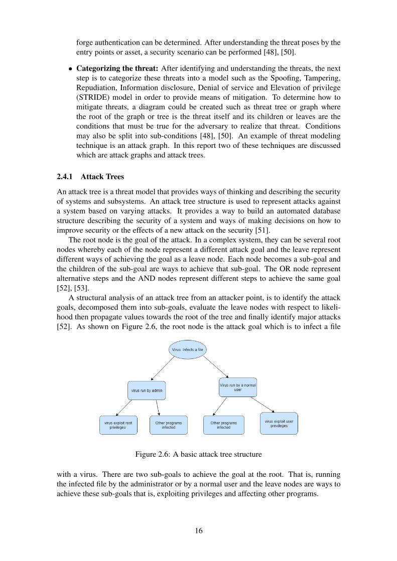
A structural analysis of an attack tree from an attacker point, is to identify the attackgoals, decomposed them into sub-goals, evaluate the leave nodes with respect to likeli-hood then propagate values towards the root of the tree and finally identify major attacks[52]. As shown on Figure 2.6, the root node is the attack goal which is to infect a file
Figure 2.6: A basic attack tree structure
with a virus. There are two sub-goals to achieve the goal at the root. That is, runningthe infected file by the administrator or by a normal user and the leave nodes are ways toachieve these sub-goals that is, exploiting privileges and affecting other programs.
16

2.4.2 Attack Graphs
Like an attack tree, an attack graph is a structural representation of all possible pathsthrough a system that end in a state where an intruder has successfully achieved his goal[54]. Attack graphs are used to model how multiple vulnerabilities may combined toperform an attack by representing systems state with a collection of security-related con-ditions such as the existence of vulnerabilities on a host or the connectivity between dif-ferent hosts [55].
There are two version of attack graphs that are widely used. The first one is a directgraph where nodes represent network states and edges represent the application of anexploit that transforms one network state into another or a more compromised networkstate. The ending states of the attack graph represent the network states in which theattacker has achieved his goal. The second one is an attack graph in the form of an exploitdependency graph. Where each node represents a pre-condition or post-condition of anexploit and edges represent the consequence of having a true precondition that enables anexploit post-condition [56], [57].
After building a graph values can be assigned to various edges to calculate the secu-rity of the goal. An example is the Common Vulnerability Scoring System CVSS whichprovides an open framework to assess the severity level of vulnerabilities. It associates aseverity score (CVSS score) to each vulnerability ranging from 0.0 to 10.0 [58].
Figure 2.7: A basic attack graph structure
As shown on Figure 2.6 and 2.7 both attack graphs and attack trees are used to representpossible paths through which an attacker can use to invade a system. However, attacktrees have a goal-decomposition approach while attack graphs have an action-sequencingapproach. As shown on Figure 2.7 there are two possible paths that can be taken to infectother files by a virus that is, running the virus by the admin or by a normal user.
Logical Attack Graphs
With respect to the attack graph on Figure 2.7, a logical attack graph (LAGs) representsthe possible actions and outcomes of actions applied by an attacker trying to gain a goalasset in a system. A logical attack graph consists of three types of nodes:
17

• Primitive fact nodes: represent facts about a system such as network connectivityand user accounts. For example, the primitive fact nodes are represented by rect-angular nodes on Figure 2.7. In this case it can be assumed that the admin or userhave an account.
• Derivation nodes or action nodes: represent an action the attacker can take inorder to gain a new capability in a system. Action nodes are represented by theovals on Figure 2.7 that is, the action here is executing an infected file with a virus.
• Derived fact nodes or privilege nodes: represent a capability an attacker gainsafter performing an action (derivation phase). For example, a node stating that theattacker can execute arbitrary code on a machine with administrative privileges.Derived fact nodes are represented by diamonds on Figure 2.7. That is, if the virusis executed by a user or admin then, the virus will gain both the admin and userprivileges to infect other files.
2.5 Risk Analysis/Assessment
Risk analysis quantifies or qualitatively describes the information security risk and en-ables organizations to prioritize risks according to their seriousness. It determines thevalue of an information assets, identifies the applicable threats and vulnerabilities thatexist or could exist, identify the existing control and their effect on the risks identified,determines the potential consequences and finally prioritizes them [59].
Furthermore, risk analysis is used to review the risks associated with an event or ac-tion. It includes processes such as identification of activity, threat analysis, vulnerabilityanalysis and any action where risks may be analyzed on a quantitative and qualitativebasis [60], [61].
The risk management process involves the following steps. Identify potential threatsan example includes the risks associated with an individual using a computer either incor-rectly or inappropriately which creates security risks.
Next, a quantitative and/or qualitative risk analysis is applied to study identified risks.Quantitative risk analysis measures expected risk probability to forecast estimated busi-ness loss from potential risks. Qualitative risk analysis does not use numbers but reviewsthreats, determines and establishes risk mitigation methods and solutions [60].
i) Security Metric
A metric is a tool designed to facilitate decision making and improve performance andaccountability through a collection and analysis of performance-related data. The purposeof measuring performance is to monitor the status of measured activities and facilitate im-provement in those activities by applying corrective actions based on observed measure-ments. A Security metric can be interpreted as a standard or system used for quantitativemeasurement of an organization security posture and they are essential to comprehensivenetwork security [62]. A good metric should have the following characteristics:
It should measure and communicate things that are relevant in a specific context forwhich they are intended and meaningful. The value of a metric should not exceed thecost, possible to track changes over time and finally it should ideally be objective andquantifiable. That is, it should be derived from a precise and reliable numeric values andnot qualitative assessment [63].
18
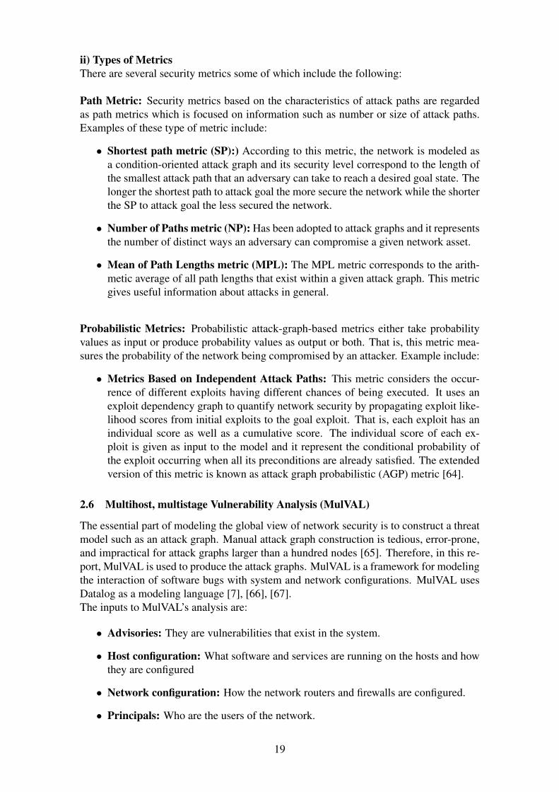
ii) Types of MetricsThere are several security metrics some of which include the following:
Path Metric: Security metrics based on the characteristics of attack paths are regardedas path metrics which is focused on information such as number or size of attack paths.Examples of these type of metric include:
• Shortest path metric (SP):) According to this metric, the network is modeled asa condition-oriented attack graph and its security level correspond to the length ofthe smallest attack path that an adversary can take to reach a desired goal state. Thelonger the shortest path to attack goal the more secure the network while the shorterthe SP to attack goal the less secured the network.
• Number of Paths metric (NP): Has been adopted to attack graphs and it representsthe number of distinct ways an adversary can compromise a given network asset.
• Mean of Path Lengths metric (MPL): The MPL metric corresponds to the arith-metic average of all path lengths that exist within a given attack graph. This metricgives useful information about attacks in general.
Probabilistic Metrics: Probabilistic attack-graph-based metrics either take probabilityvalues as input or produce probability values as output or both. That is, this metric mea-sures the probability of the network being compromised by an attacker. Example include:
• Metrics Based on Independent Attack Paths: This metric considers the occur-rence of different exploits having different chances of being executed. It uses anexploit dependency graph to quantify network security by propagating exploit like-lihood scores from initial exploits to the goal exploit. That is, each exploit has anindividual score as well as a cumulative score. The individual score of each ex-ploit is given as input to the model and it represent the conditional probability ofthe exploit occurring when all its preconditions are already satisfied. The extendedversion of this metric is known as attack graph probabilistic (AGP) metric [64].
2.6 Multihost, multistage Vulnerability Analysis (MulVAL)
The essential part of modeling the global view of network security is to construct a threatmodel such as an attack graph. Manual attack graph construction is tedious, error-prone,and impractical for attack graphs larger than a hundred nodes [65]. Therefore, in this re-port, MulVAL is used to produce the attack graphs. MulVAL is a framework for modelingthe interaction of software bugs with system and network configurations. MulVAL usesDatalog as a modeling language [7], [66], [67].The inputs to MulVAL’s analysis are:
• Advisories: They are vulnerabilities that exist in the system.
• Host configuration: What software and services are running on the hosts and howthey are configured
• Network configuration: How the network routers and firewalls are configured.
• Principals: Who are the users of the network.
19

• Interaction: What is the model of how all these components interact.
• Policy: Access control to network resources that is, what access to the networkresources should be permitted [7], [67].
Basic syntax: The Datalog syntax in prolog uses the following terms:
• Atoms: They are strings made up of lower and uppercase letters such as abc, aBC.
• Variables: They are strings of letters, digits and underscores starting with an upper-case letter. A Prolog program is made up of facts and rules also known as clauseswhich are used to defined predicates.
• Facts: They are predicates follow by a full stop. Example person (Name, tanyi).Fact define a certain instance of relation of being true. Here the example says aperson has name as tanyi and name is a variable since a person can have any name.
• Rule: A rule consists of a head or predicate and a body or sequence of predicatesseparated by commas. The head and body are separated by the symbol (:-) and, likeevery Prolog expression, a rule must be terminated by a full stop. Example:aunt (Aunt, Child): -sister (Aunt, Parent),parent (Parent, Child), [68].This rule states that for a person to be an aunt to a child she must be a sister to theparent of the child. MulVAL takes in two files to produce an attack graph. Theinput file and the rule file. The input file takes in facts or predicates and the rule filetakes the rules to ascertain the fact in the input file of being true.
2.7 Related work
There are several research papers about the security of software defined networking (SDN).Most of these papers used different approach to determine the vulnerabilities of SDN ar-chitecture. However, some of these papers also used the approach of threat modeling suchas flow graphs to determined possible attacks on the SDN architecture. Figure 2.8 shows
Figure 2.8: Flow graph.
a simple flow graph with possible paths from H1 to H2. SPHINX is a framework usedto detect attacks on a network topology [69]. The flow graph on Figure 2.8 is used bySPHINX to detect both known and potentially unknown attacks on the network topology
20
and data plane forwarding originality. The flow paths are constructed using FLOW-MODmessages which are issued by the trusted controller. SPHINX use the abstraction of flowgraphs which are closely approximate to the actual network operations, to enable incre-mental validation of all network updates and constraints. SPHINX dynamically learnsnew network behavior and raises alerts when it detects suspicious changes in the existingnetwork control plane behavior [69].
Vulnerability or risk analysis have also been performed in SDN using a CommonVulnerability Scoring System (CVSS) to estimate the impacts of security vulnerabilities.CVSS is based on qualitative and quantitative metrics that define the impacts of the se-curity vulnerabilities. Its computation procedures integrate three dimensions related tothe different characteristics of classical networks. That is, the intrinsic generic featuresof computer systems, their temporal features and their environment related factors. How-ever, there are significant factors specific to SDN which are not covered by CVSS. Thesefactors affect the security of SDN and enlarges it vulnerability surface. For example, thecentralization of the Controller transforms its components to precarious shared resourcesamong other SDN assets.
In this case, all the SDN assets are exposed by the vulnerabilities of the Controller.Thus, a proper vulnerability analysis also needs to integrate specific SDN features into theevaluation of vulnerability impacts. Therefore, the Analytical Hierarchy Process (AHP)is one of these approaches. It is a multi-criteria decision-making procedure which enablesthe measurements of the overall intensities of SDN characteristics on the severity of itsvulnerabilities [70].
21
3 Method
3.1 Scientific approach
As mentioned in chapter 2.4 and 2.5, risk analysis process involves the following steps.Identify potential threats, understand the threats, categorize the threats and determinetheir potential consequences and finally prioritizes them. These threats can be identified,understand and categorize using flow graphs as mentioned in the related work chapter orusing some modeling language like Unified Modeling Language (UML). The final goal ofthis project is to perform risk analysis on the OpenFlow SDN model using a threat model.In this project, an attack graph is used which can scale very large networks compared toUML and flow graphs.
To limit the scope of this project, after investigating different SDN models and theirvulnerabilities we selected the OpenFlow based model since it is limited only to the SDNnetwork itself unlike the overlay and the hybrid model which are interconnected to thephysical network. Then we selected a few concrete attack scenarios extracted from theexisting literature based on OpenFlow vulnerabilities with the aid of figures. Therefore,these attacks are solely associated to the OpenFlow SDN model only. In addition tothe figures, we modeled these vulnerabilities into datalog facts/predicates and rules. Thenused a framework known as MulVAL which takes these facts and rules as input to producea threat model known as attack graph. Furthermore, we analyzed the attacks by perform-ing risk analysis on the generated attack graphs which enable us to better understand thethreat of these attacks on the SDN network.
3.2 Method description
We used different methods to achieve the objectives of this project. Firstly, we conducteda series of literature research from different source by consulting a wide variety of pa-pers related to the security of software defined networking. While consulting these paperswe tried to prioritize the recent materials over older materials. Furthermore, we alsoconsulted papers from a more reputable sources over papers of inferior quality and char-acteristics. We looked for papers in the following websites: LNU University Library OneSearch, Google Scholar, Research-Gate and ACM Digital Library. Apart from researchpapers, our literature research was also complemented with books and web articles relatedto the security of software defined networking.
Secondly, we looked for concrete vulnerabilities in the OpenFlow SDN model. Thirdlywe created attack scenarios based on some of the vulnerabilities associated to the Open-Flow SDN model. After creating these attack scenarios, we defined entities and propertiescorresponding to each attack scenario. These entities and properties are considered as dat-alog facts in MulVAL and they are placed in the input file. The rule file takes the rules toascertain the facts in the input file of being true. Therefore, we created rules to ascertainthe entities and properties created in the input file to produce a threat model known asattack graph.
Finally, we analyzed the graph to perform risk analysis and assessment with the aid ofa metric which had already been implemented with a Java Program by Charilaos Skandy-las who is a co-supervisor of this project. This Java program calculate some metrics suchas the number of paths and shortest path to attack goal on the graph. Therefore, we gaveour input and rule files as parameters to the java program to calculate the metric.
22
3.3 Attack Scenarios
After looking into the SDN architecture, different SDN models and SDN vulnerabilities,attack scenarios are created using these vulnerabilities which are further used for threatmodeling. However, before the attack scenarios are demonstrated, this report explainshow SDN works with respect to the attack before the actual attack. H denote a networkhost, H1, H2, Hn where n is 1,2, 3...n denotes the different hosts
3.3.1 Before attack on the SDN Controller with a malicious application
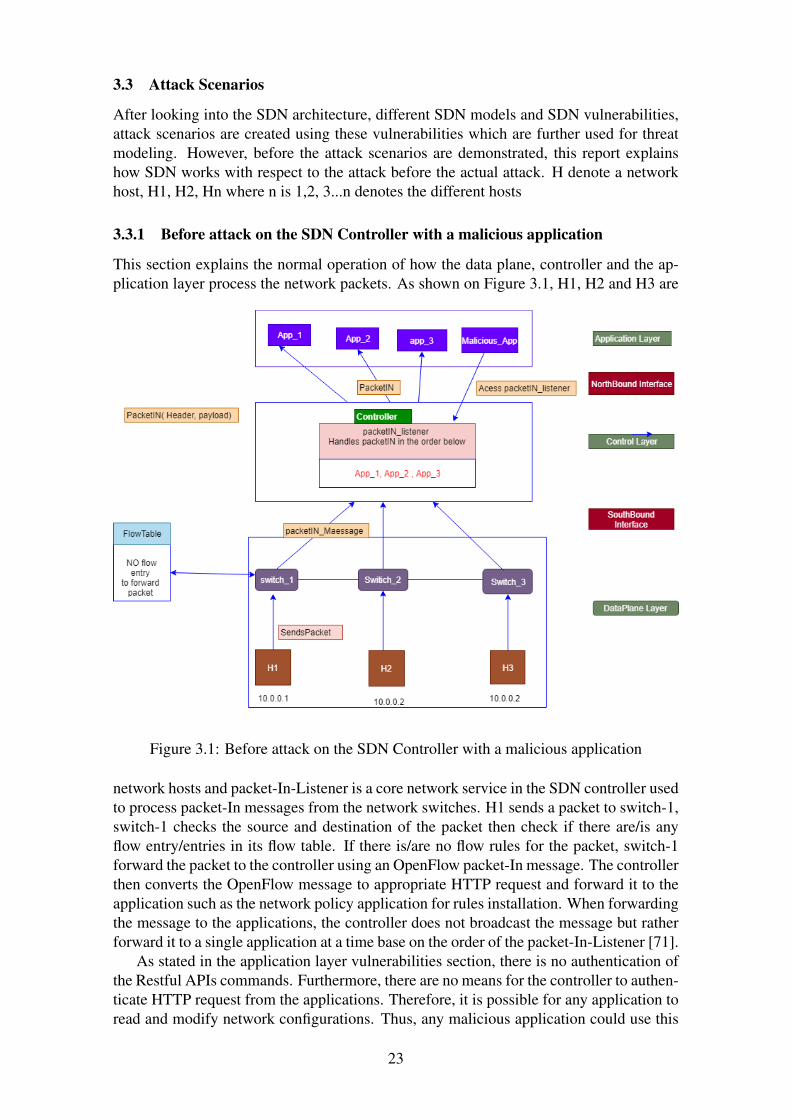
This section explains the normal operation of how the data plane, controller and the ap-plication layer process the network packets. As shown on Figure 3.1, H1, H2 and H3 are
Figure 3.1: Before attack on the SDN Controller with a malicious application
network hosts and packet-In-Listener is a core network service in the SDN controller usedto process packet-In messages from the network switches. H1 sends a packet to switch-1,switch-1 checks the source and destination of the packet then check if there are/is anyflow entry/entries in its flow table. If there is/are no flow rules for the packet, switch-1forward the packet to the controller using an OpenFlow packet-In message. The controllerthen converts the OpenFlow message to appropriate HTTP request and forward it to theapplication such as the network policy application for rules installation. When forwardingthe message to the applications, the controller does not broadcast the message but ratherforward it to a single application at a time base on the order of the packet-In-Listener [71].
As stated in the application layer vulnerabilities section, there is no authentication ofthe Restful APIs commands. Furthermore, there are no means for the controller to authen-ticate HTTP request from the applications. Therefore, it is possible for any application toread and modify network configurations. Thus, any malicious application could use this
23

vulnerability to read and modify the entire network state. In this case, it is assumed thatthere is a malicious application that can access the packet-In-Listener as shown on Figure3.1 above.
3.3.2 Attack on the SDN controller with a malicious application
Here is the description of what happened when the malicious application accesses thepacket-In-Listener.
Figure 3.2: Attack on the SDN controller with a malicious application
The malicious application accesses the packet-In-Listener and reorder the packet-In-Listenersuch that, whenever the controller forwards any request to the applications, the maliciousapplication should be the first to get the packet-In message. Therefore, whenever H1 sendsa packet again to switch-1 and there is/are no flow rules to forward the packet, switch-1forward it to the controller using the packet-In message then the controller forwards thepacket-In message to the applications. Based on the order of the packet-In-Listener, themalicious application gets the packet-In message first before any other application [71].
The malicious application then removes the payload from the packet-In message andforward it to app-1. Then, app-1 tries to process the packet-In message but throws anexception to the controller instead since the payload of the packet-In message has beenremoved by the malicious application. Since the controller cannot handle exceptions, thecontroller disconnects both from the applications and the switches [71].
24

3.3.3 Before attack on Link Layer Discovery Protocol (LLDP)
This section explains the normal operation of the link layer discovery protocol in the SDNnetwork.
Figure 3.3: Before attack on Link Layer Discovery Protocol
The link layer discovery protocol (LLDP) format is used by the OpenFlow DiscoveryProtocol (OFDP) to discover the links between nodes on the network. To do this, theSDN controller create an individual LLDP packet for each port on the switch and eachof these packets have several properties but the most important properties for the linkdiscovery are the Chassis ID (unique device identifier) and the source Port ID. Thesepackets are sent by the controller through separates OpenFlow packet-Out messages withinstruction on how to send the packet out on the corresponding port. All the switches havepre-installed rules in their flow tables which says that any LLDP packet received from anyport except the controller port, is to be forwarded to the controller through an OpenFlowpacket-In message [72].
The packet-In message also contains meta data, such as the ID of the switch and thesource/input port though which the packet was received. From this information containedin the header and payload of the LLDP packet, that is the Chassis ID and Port ID, thecontroller can infer the existence of links between network components. From Figure3.3 above, it is assumed that the LLDP packets have already been sent to switch-1 andswitch-3 through a packet-Out message. From the left-hand corner of the figure, there aretwo LDDP packets one each sent from H1 and H3. Since the first LLDP packet headercontain the Chassis ID of H1 and the Port ID P1, the payload has the Chassis ID switch-1and the same Port ID P1. The second LLDP packet header has the Chassis ID of H3 andthe Port ID P1, the payload contain the Chassis ID switch-3 and the Port ID P1. When thecontroller receives both LLDP packets from switch-1 and switch-3 through the packet-Inmessage, the information in the header and payload is used to deduce the existence of a
25

link between H1 and switch-1 through Port 1 and another link between H3 and switch-3through Port 1 [72].
3.3.4 Attack on Link Layer Discovery Protocol
As stated in the previous section, OFDP does not check or enforce that LLDP packetsare only received through switch ports that are connected to another switch. That is,LLDP packets from host ports are also accepted and are forwarded to the controller. Fur-thermore, there is no authentication or integrity check of LLDP control messages. Thecontroller has no way of verifying the origin of the packets. Therefore, it is possible tospoof links between nodes by modifying the LDDP packet [72].
Figure 3.4: Attack on Link Layer Discovery Protocol
As shown above on Figure 3.4, H1 and H3 modifies the LLDP packet header to createspoof links between them. H1 set it Chassis ID to H3 and Port ID to p1 while H3 set itChassis ID to H1 an Port ID to P1. when switch-1 and switch-3 forward the LLDP packetsfrom H1 and H3 respectively to the controller. The packet header from H1 has a ChassisID set to H3 and port ID P1, the payload also has the Chassis ID of switch-1 and the PortID P1 thus the controller concludes that the exist a direct link between switch-1 and H3.Furthermore, the packet header from H3 has the Chassis ID H1 and the Port ID P1, thepayload has the Chassis ID of switch-3 and the Port ID P1. With this information, thecontroller draws another conclusion that the exist another direct link from H3 to switch-1through Port 1. If H1 and H3 tries to communicate with each other though the fake links,the routing protocol is disrupted which breaks down the network connectivity betweenthe network components [72].
26

3.3.5 Before Man-in-the-middle attack on OpenFlow Switches
Here is another description of how the flow entries in an OpenFlow switch enables twoend hosts to communicate with each other.
Figure 3.5: Before Man-in-the-middle attack on OpenFlow Switches
As stated in the previous section the OpenFlow switch flow table have three main fields ofentry. The counter, the header field which checks the source and destination of a packetand the action filed which consist of instructions on how the packet should be processbased on the source and destination port.
Figure 3.5 above shows a straight forward demonstration of how the flow entries areentered in an OpenFlow switch flow table for H1 and H2 to communicate.
27

3.3.6 Man-in-the-middle attack on OpenFlow Switches
Here is the proper description of an attack based on the OpenFlow switch flow tablemodification. All OpenFlow switches allow anyone to connect to them from any network
Figure 3.6: Man-in-the-middle attack on OpenFlow Switches
through their passive listening ports. Most OpenFlow switches are debug remotely usingthese passive listening ports which allow access to the flow table. Therefore, it is possiblefor an attacker to connect to OpenFlow switches through these passive listener ports usingsome tools or common utilities like dpctl which is a management utility that enablescontrol over OpenFlow switches to modify their configurations [73], [21].
As shown on Figure 3.6 above, HA represent an attacker host who is connected to anOpenFlow switch through the OpenFlow passive listener port from an external networkwith the aim of modifying the switch flow table in order to listen and deviate communica-tion between H1 and H2 to HA. The attacker deviate traffic from H1 to HA and becomethe source. Then forward the traffic to H2. When H2 tries to communicate with H1 theattacker deviates the traffic from H2 to HA and become the source again then forward itto H1 thus HA is considered as man-in-the-middle. OpenFlow switches usually send aFlow-Removed message to the controller when a flow entry is removed but, in this case,the attacker does not remove the flow entry but rather modifies the flow entry [21].
28

3.3.7 Attack on flooding the OpenFlow switch and the controller
An OpenFlow switch has a buffer to temporary store packets before processing them andthe controller also has a buffer to handle network requests from the data plane such aspacket-In messages.
Figure 3.7: Attack on flooding the OpenFlow switch and the controller
As shown on Figure 3.7, the switch can be flooded as well as the controller. This attackassumed that, an attacker connects to the OpenFlow switch through a passive listeningport from an external host HA, then send packets to flood the switch [41].
When HA sends packets to switch-1, switch-1 forward it to the controller to installrules for the packets through an OpenFlow packet-In message. In this case, it is assumedthat the max buffer size for the switch is 10 but however the attacker sends 20 packetswhich is twice the buffer size. Therefore, switch-1 is flooded with packets as well as thecontroller with packet-In messages [41].
3.4 Attack Modeling
As stated in the previous section, entities and properties or facts are defined for eachattack scenario. These entities and properties are given to MulVAL as inputs and rulesare created to ascertain these facts in order to create an attack graph. Table 3.1 shows theentities and properties for all the attack scenarios.
29

Entities PropertiesisAttackerHost(chassisID, hostA, ip, ’192.168.10.5’, portID, p3). maliciousApp (app1, app2app3).isAppLayer(app1, app2, app3, maliciousApp). switchPorts(port, sourcePort, p1, destinationPort, p2)isApp(app1). attackerLoacted(hostA, tcp, internet).isApp(app2). attackerLocated(host1).isApp(app3). attackerLoacted(host3).isApp(maliciousApp). headerModified(header, chassisID, host1, portID, p1).isController(controller). headerModified(header, chassisID, host3, portID, p1).isSwitch(switch1). switchPorts(sourcePort, p1, destinationPort, p2, listenerPort ,p3).isSwitch(switch2). maxBufferCapacity(maxcapacity, 10).isSwitch(switch3). currentBufferCapacity(currentCapacity 20).isFlowTable(table, entry, switch1). packetInPayloadRemoved(packetIn, header).isFlowEntry(entry, sourceIP, ip , destinationIP, ip, action). fakeNetworkLinks(host1, switch3, portID, p1).isAction(action, forwardTo, destinationPort, none). fakeNetworkLinks(host3, switch1, portID, p1).isHost(chassisID, host1, ip, ’10.0.0.1’, portID, p1). orderOfpacketInListener(packetIn, app1,app2,app3 maliciousApp).isHost(chassisID, host1, ip, ’10.0.0.2’, portID, p1). orderOfpacketInListenerModify(packetIn,maliousApp, app1,app2).isHost(chassisID, host1, ip, ’10.0.0.3’, portID, p1).isBuffer(maxCapacity, currentCapacity).isPacket(packet).isPacketIn(packetIn, header, payload).isLlDPPacket(lldpPacket, header, payload).isPayload(payload, chassisID, switch1, p1)isException(exception, app1, controller).isFlowEntry(entry, srcIP, ’10.0.0.1’ destIP, ’10.0.0.2. action).isAction(action, ’input=p1’, ’output=p2’, ’addEntry, set-dest-IP =192.168.10.5 output=p3’).isFlowEntry(entry, srcIP, ’192.168.10.5’, destIP, ’10.0.0.2’ action).isAction(action, ’input=p3’,’output =p2’, addEntry, ’set-src-IP =10.0.0.1, output=p2’).isFlowEntry(entry, srcIP,’10.0.0.2’, destIP, ’10.0.0.1’ action).isAction(action, ’input=p2’, ’output=p1’, addEntry, set-dest-IP =192.168.10.5 output=p3’).isFlowEntry(entry, srcIP, ’192.168.10.5’ destIP, ’10.0.0.1’, action).isAction(action, ’input=p3’, ’output=p1’, addEntry, ’set-src-IP =10.0.0.2 output=p1’)
Table 3.1: Entities and properties for all attack scenarios
3.4.1 Rules for attack on controller with a malicious application
As stated in section 2.6, a rule consists of a head and a body separated by the symbol (: -)which is a conditional statement "IF" in most programming languages
To initiate this attack, the first rule below sends a packet from a host1 to switch1 baseon the name of the rule, (packetSendFromHostToSwitch) if (:-) there is a host connectedto switch1 on port 1, a packet and switch-1 to receive the packet through port 1 fromhost1.
interaction_rule((packetSendFromHostToSwitch(Packet, Host1, Switch1):-isSwitch(switch1),isPacket(Packet),isHost(ChassisID,host1,IP, Add, PortID, P1)),
rule_desc(’host1 sends a packet to switch1’,1)).
The second rue below is switchSentPackInToController if (:-) switch1 received a packetfrom host1 base on the first rule above (packetSendFromHostToSwitch) and the packetdo not match any flow entry in the flow table of switch-1 (noFlowEntryForPacket), thenswitch-1 should send a packet-In message (isPacketIn) to the controller (isController) forrule installation.
interaction_rule((switchSentPackInToController (PacketIn, Controller): -
packetSendFromHostToSwitch (Packet, Host, Switch),isSwitch (Switch1),switchports (Port, SourcePort, P1, DestinationPort, None).noFlowEntryForPacket(Table, Entry, Switch1),isPacketIn(PacketIn,Header,Payload),isController(Controller)),
30
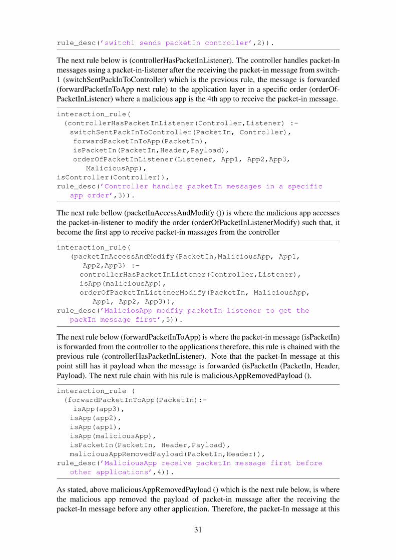
rule_desc(’switch1 sends packetIn controller’,2)).
The next rule below is (controllerHasPacketInListener). The controller handles packet-Inmessages using a packet-in-listener after the receiving the packet-in message from switch-1 (switchSentPackInToController) which is the previous rule, the message is forwarded(forwardPacketInToApp next rule) to the application layer in a specific order (orderOf-PacketInListener) where a malicious app is the 4th app to receive the packet-in message.
interaction_rule((controllerHasPacketInListener(Controller,Listener) :-switchSentPackInToController(PacketIn, Controller),forwardPacketInToApp(PacketIn),isPacketIn(PacketIn,Header,Payload),orderOfPacketInListener(Listener, App1, App2,App3,
MaliciousApp),isController(Controller)),rule_desc(’Controller handles packetIn messages in a specific
app order’,3)).
The next rule bellow (packetInAccessAndModify ()) is where the malicious app accessesthe packet-in-listener to modify the order (orderOfPacketInListenerModify) such that, itbecome the first app to receive packet-in massages from the controller
interaction_rule((packetInAccessAndModify(PacketIn,MaliciousApp, App1,
App2,App3) :-controllerHasPacketInListener(Controller,Listener),isApp(maliciousApp),orderOfPacketInListenerModify(PacketIn, MaliciousApp,
App1, App2, App3)),rule_desc(’MaliciosApp modfiy packetIn listener to get the
packIn message first’,5)).
The next rule below (forwardPacketInToApp) is where the packet-in message (isPacketIn)is forwarded from the controller to the applications therefore, this rule is chained with theprevious rule (controllerHasPacketInListener). Note that the packet-In message at thispoint still has it payload when the message is forwarded (isPacketIn (PacketIn, Header,Payload). The next rule chain with his rule is maliciousAppRemovedPayload ().
interaction_rule ((forwardPacketInToApp(PacketIn):-
isApp(app3),isApp(app2),isApp(app1),isApp(maliciousApp),isPacketIn(PacketIn, Header,Payload),maliciousAppRemovedPayload(PacketIn,Header)),
rule_desc(’MaliciousApp receive packetIn message first beforeother applications’,4)).
As stated, above maliciousAppRemovedPayload () which is the next rule below, is wherethe malicious app removed the payload of packet-in message after the receiving thepacket-In message before any other application. Therefore, the packet-In message at this
31

point has no payload (isPacketIn (PacketIn, Header)) but just a header.
interaction_rule((maliciousAppRemovedPayload(PacketIn,Header) :-isApp(app1),isPacketIn(PacketIn, Header),isApp(maliciousApp)),
rule_desc(’MaliciosApp remove payload and send the packet toapp1’,6)).
The next rule below (appThrowsExceptionsToController) is chained with the previousrule (maliciousAppRemovedPayload) above. This rule shows what happen when the ma-licious app removed the payload from the packet-in message and forward the packet-inmessage to appl (isApp(app1)). App1 throws an exception to the controller (isException(Exception, App1, Controller).
interaction_rule((appThrowsExceptionsToController(Exception, App1,Controller)
:-maliciousAppRemovedPayload(PacketIn,Header),isException(Exception, App1, Controller),isController(Controller),isApp(app1)),
rule_desc(’App1 throws exceptions to the controller since thepayload of the packet-In has been removed’,7)).
When app1 throws an exception to the controller according the previous rule above, thenext rule below (controllerDisconnectedFromApp) is the effect of the exception. That is,the controller is disconnected from the application layer since the controller cannot handleexceptions.
interaction_rule((controllerDisconnectedFromApp(Controller, App1):-appThrowsExceptionsToController(Exception, App1,Controller),isController(Controller),isApp(app1)),
rule_desc(’controller disconneted from app since it cannothandle exceptions’,8)).
The next rule below (switchDisconnectedFromController) is the second effect where thecontroller disconnects from switch1
interaction_rule((switchDisconnectedFromController(Controller, Switch1):-isSwitch(Switch1),isController(Controller)),
rule_desc(’Switch disconneted from the controller’,9)).
Therefore, the last rule below dataplanConnectionDown is the goal of this attack. wherethe controller is disconnected both from the application layer and the data plane. It canalso be assumed that the entire network is down in the case where the SDN applicationsare implemented as internal modules.
32

interaction_rule((dataplanConnectionDown(Switch,Controller):-switchDisconnectedFromController(Controller, Switch),switchFlooded(Switch1),controllerDisconnectedFromApp(Controller, App1)),
rule_desc(’controller disconneted from app and switch thusdataplanConnectionDown’,10)).
3.4.2 Rules for attack on Link Layer Discovery Protocol
For this attack it is assume that host1 and host3 are compromised by an attacker (attacker-Located(host1/3). Therefore, the first rule below(modfiyLLDPpacketFromHost1ToSwitch1)is where the attacker sends a LLDP packet with a modify header (headerModified (header,chassisID, host3, PortID, p1) from host1 to switch1. Note that the modify header has achassis ID of host3 meanwhile the packet if sent from host1.
interaction_rule((modfiyLLDPpacketFromHost1ToSwitch1(host1, lLDPpacket,
switch1) :-attackerLocated(host1),headerModified(header, chassisID, host3, PortID, p1),isLLDPPacket( LLDPpacket, Header, Payload),isPayload(Payload, ChassisID, switch1, P1),isHost(ChassisID, host1, IP, Addrs, PortID, P1)),
rule_desc(’Modify lLDPpacket from host1 to switch1’,5)).
Like the rule above, the next rule (modfiyLLDPpacketFromHost3ToSwitch3) is wherethe attacker sends another LLDP packet with a modify header (headerModified (header,chassisID, host1, PortID, p1) from host3 to switch3 with the chassis ID set to host1.
interaction_rule((modfiyLLDPpacketFromHost3ToSwitch3(host3, lLDPpacket,
switch3) :-attackerLocated(host3),isSwitch(switch3),headerModified(header, chassisID, host1, PortID,p1),isHeader(header, chassisID, host3, portID, p1),
isLLDPPacket( LLDPpacket, Header, Payload),isPayload(Payload, ChassisID, switch3, P1),
isHost(ChassisID, host3, IP, Addrs, PortID, P1)),rule_desc(’Modify lLDPpacket from host3 to switch3’,6)).
The next is rule (dataPlaneCompromised) is the sub-goal of this attack. Where the dataplane is compromised with fake links if host1 and host3 both sent a modify LLDP packetto switch1 and switch3 respectively.
interaction_rule ((dataPlaneCompromised (hosts, switches): -modfiyLLDPpacketFromHost3ToSwitch3(host3, lLDPpacket,
switch3),fakeTopologyViewByController(Controller, Host, Switches),isHost(ChassisID, host3, IP, Addrs,PortID,P1),
33

isSwitch(switch3),isPacketIn(packetIn, header, payload),isHost(ChassisID, host2, IP, Addr,PortID,P1),isSwitch(switch2),isSwitch(switch1),isHost(ChassisID, host1, IP, Add,PortID,P1),
modfiyLLDPpacketFromHost1ToSwitch1(host1, lLDPpacket,switch1)),
rule_desc(’data plane components compromised with fakes linksand by man-in-the-middle’,1)).
The last rule below (fakeTopologyViewByController) is the attack goal which is chainedwith the previous rule. This is where the controller gets a fake topology view aboutthe network when it received the LLDP packets with modify headers from switch1 andswitch3 through a packet-in messages. That is the controller thinks the exist a directlink between host1 and switch3 connected on port1 (fakeNetworkLinks (host1, switch3,portID, p1)) and another direct link between host3 and switch connected via port1 (fak-eNetworkLinks (host3, switch1, portID, p1))
interaction_rule((fakeTopologyViewByController(Controller, Host, Switches) :-isController(Controller),isPacketIn(packetIn, header, payload),fakeNetworkLinks(host1, switch3,portID, p1),
fakeNetworkLinks(host3, switch1,portID, p1),headerModified(header, chassisID, host3, PortID,p1)),headerModified(header, chassisID, host1, PortID,p1)),
rule_desc(’Controller get new modified topology view about thelinks’,7)).
3.4.3 Rules for Man-in-the-middle attack on OpenFlow switch
For this attack the goal is deviate network traffic between two end hosts by modifyingan OpenFlow switch flow table. To initiate this attack, the first rule below (attackerCon-netedToSwitch) show the step used by an attacker to connect to OpenFlow switch. Theattacker is located on the internet (attackerLocated (HostA, Tcp, Internet)) and make aTCP connection to switch1 through a listener port3.
interaction_rule((attackerConnetedToSwitch(HostA, ListenerPort,Tcp, Switch1)
:-switchPorts(SourcePort, P1,DestinationPort, P2,
ListenerPort, P3),isAttackerHost(ChassisID, hostA, Ip, Add, PortID, p3),isSwitch(switch1),attackerLocated(HostA, Tcp, Internet)),
rule_desc(’Attacker connected to switch via a listener portusing a tcp connection’,1)).
The rule below is what the attacker does after connecting to switch1. That is (attack-erModifyFlowtableEntryOfHost1ToHost2) the attacker modifies the flow entries in the
34

flow table to deviate traffic from host1 to hostA which is his own host (isAction (action,input=p1, output=p2, addEntry, set-dest-IP=192.168.10.5 output=p3)) and becomes thedestination to host1. Then add another flow entry to forward the traffic from his own hostto host2 which is the right destination and becomes the source to host2 (isAction (action,input=p3’, output=p2, addEntry, set-src-IP=10.0.0.1= output=p2)).
interaction_rule((attackerModifyFlowtableEntryOfHost1ToHost2(Flowtable,
Entry):-attackerConnetedToSwitch(HostA, ListenerPort,Tcp, Switch1),isFlowEntry(Entry, sourceIP, ’10.0.0.1’, destinationIP,
’10.0.0.2’, action),isAction(action, ’input=p1’, ’output=p2’, addEntry,
’set_dest_IP=192.168.10.5 output=p3’),isFlowEntry(entry, sourceIP, ’192.168.10.5’, destinationIP,
’10.0.0.2’, action),isAction(action, ’input=p3’, ’output=p2’, addEntry,
’set_src_IP=10.0.0.1= output=p2’),isFlowTable(table, entry, switch1)),
rule_desc(’Attacker add new flow rules to deviate trafffic fromhost1 to hostA’,2)).
The next rule below is (attackerModifyFlowtableEntryOfHost2ToHost1) is where the at-tacker adds two more flow entries. First the attacker adds an entry to deviate traffichost2 to his own hostA (isAction (action, input=p2, output=p1, addEntry, set-dest-IP=192.168.10.5 output=p3’) to become the destination to host2. Then add another flow en-try to forward the traffic from his own hostA to host1 thereby becoming the source to host1(isAction (action, ’input=p3’, ’output=p1’, addEntry, set-src-IP= 10.0.0.2 output=p1).
interaction_rule((attackerModifyFlowtableEntryOfHost2ToHost1(Flowtable,
Entry):-isFlowEntry(entry, sourceIP, ’10.0.0.2’, destinationIP,
’10.0.0.1’, action),isAction(action, ’input=p2’, ’output=p1’, addEntry,
’set_dest_IP= 192.168.10.5 output=p3’),isFlowEntry(entry, sourceIP, ’192.168.10.5’, destinationIP,
’10.0.0.1’, action),isAction(action, ’input=p3’, ’output=p1’, addEntry,
’set_src_IP= 10.0.0.2 output=p1’),attackerConnetedToSwitch(HostA, ListenerPort,Tcp, Switch1),isFlowTable(table, entry, switch1)),
rule_desc (’Attacker add another new flow rule to deviatetraffic from host2 to hostA’,2)).
The last attack below (trafficDeviatebetweenHostByAttacker (host1, host2) is the attackgoal of this attack which is chained with the two previous rules above (attackerModi-fyFlowtableEntryOfHost1ToHost2) and (attackerModifyFlowtableEntryOfHost2ToHost1)that is, the network traffic is deviated between host1 and host2 if there is man-in-the-middle between them modifying the network traffic.
interaction_rule((trafficDeviatebetweenHostByAttacker(host1, host2):-
35

attackerModifyFlowtableEntryOfHost2ToHost1(Flowtable, Entry),isHost(ChassisID, host2, IP, Addrs, PortID, P1),isAttackerHost(ChassisID, hostA, IP, Add, PortID, P3),isHost(ChassisID, host1, IP, Addr ,PortID, P1),
attackerModifyFlowtableEntryOfHost1ToHost2(Flowtable, Entry)),rule_desc(’Traffic deviated by attacker between host1 and
host2’,3)).
3.4.4 Rules for attack on flooding the switch and the controller
The goal of this attack is to bring down the network connection at the data plane by flood-ing the switch with packets and the controller with packet-in messages. Like the previousattack above the attacker (hostASendPacketsToFloodSwitch) connect to the OpenFlowswitch through a listener port P3 (isAttackerHost (chassisID, hostA, ip, 192.168.10.5,portID, p3) and sends packet from hostA to flood switch1.
interaction_rule((hostASendPacketsToFloodSwitch(Packet, Switch1) :-attackerLocated(hostA, tcp, internet),isPacket(Packet),switchPorts(sourcePort, p1, destinationPort, p2,
listenerPort, p3),isAttackerHost(chassisID, hostA, ip, ’192.168.10.5’,portID,
p3)),rule_desc(’Attacker connect to switch via a listener port and
sends packet to flood it’,9)).
The next rule below is chained with the first rule (hostASendPacketsToFloodSwitch)where switch1 is flooded (switchFlooded(switch1) if its max buffer size M is less thanits current buffer size C.
interaction_rule((switchFlooded(switch1):-controllerFlooded(PacketIn),isFlowTable(Table, Entry, Switch1),isBuffer(maxCapaticy, currentCapacity),maxBufferCapacity(MaxCapaticy, M),currentBufferCapacity(CurrentCapacity, C),isPacketIn(PacketIn, _, _),switchPorts(sourcePort, p1, destinationPort, p2,
listenerPort, p3),isSwitch(switch1),hostASendPacketsToFloodSwitch(Packet)),
rule_desc(’Switch1 flooded if the current buffer size isgreater than the max buffer size’,10)).
The next rule (controllerFlooded(PacketIn) is where the controller is flooded with packet-in messages from switch1 ( isPacketIn(PacketIn)
interaction_rule((controllerFlooded(PacketIn):-isPacketIn(PacketIn, _, _),
36

isController(Controller)),rule_desc(’Controller flooded with packIn messages’,21)).
The last rule below (dataplanConnectionDown) is the attack goal which implies that if(:-) data plane connection is down, then it means switch1 is flooded thus causing denialof service in the data plane connection.
interaction_rule((dataplanConnectionDown(Switch,Controller):-switchDisconnectedFromController(Controller, Switch),switchFlooded(Switch1),controllerDisconnectedFromApp(Controller, App1)),
rule_desc(’controller disconneted thusdataplanConnectionDown’,10)).
3.4.5 Combining Attacks
After modeling the individual attack above, the goals and sub-goals of these attacks aremerged to create one complex attack.
The first rule (trafficDeviatebetweenHostByAttacker) below is the attack goal for the sec-ond attack where the network traffic is deviated between two end hosts when the attackermodified the flow table entries.
interaction_rule((trafficDeviatebetweenHostByAttacker(host1, host2):-attackerModifyFlowtableEntryOfHost2ToHost1(Flowtable, Entry),isHost(ChassisID, host2, IP, Addrs, PortID, P1),isAttackerHost(ChassisID, hostA, IP, Add, PortID, P3),isHost(ChassisID, host1, IP, Addr ,PortID, P1),
attackerModifyFlowtableEntryOfHost1ToHost2(Flowtable, Entry)),rule_desc(’Traffic deviated by attacker between host1 and
host2’,3)).
The next rule (fakeTopologyViewByController) is the attack goal for third attack scenariowhere the controller gets a fake topology view when it received modified LLDP packetsfrom host1 and host3.
interaction_rule((fakeTopologyViewByController(Controller, Host, Switches) :-isController(Controller),
isPacketIn(packetIn, header, payload),fakeNetworkLinks(host1, switch3,portID, p1),
fakeNetworkLinks(host3, switch1,portID, p1),headerModified(header, chassisID, host1, PortID,p1)),
rule_desc(’Controller get new modified topology view about thelinks’,7)).
Th next rule (dataPlaneCompromised) below is considered as a sub-attack goal whichcombined the second and the third attack scenario. That is the data plane is compromisedwith fake links and by man-in-the-middle if modified LLDP packets are received fromhosts and if there is an unauthorized access to the OpenFlow switch respectively.
37

interaction_rule((dataPlaneCompromised(hosts, switches):-modfiyLLDPpacketFromHost3ToSwitch3(host3, lLDPpacket,
switch3),fakeTopologyViewByController(Controller, Host, Switches),isHost(ChassisID, host3, IP, Addrs,PortID,P1),
isSwitch(switch3),isPacketIn(packetIn, header, payload),isHost(ChassisID, host2, IP, Addr,PortID,P1),isSwitch(switch2),isSwitch(switch1),isHost(ChassisID, host1, IP, Add,PortID,P1),
modfiyLLDPpacketFromHost1ToSwitch1(host1, lLDPpacket,switch1)),
rule_desc (’data plane components compromised with fakes linksand by man-in-the-middle’,1)).
The last rule below is the attack goal for the first and the fourth attack scenario. That is,the data plane connection is down if the controller is disconnected from the data pane andfrom the app layer. The data plane connection is also down if the switches are flooded.
interaction_rule((dataplanConnectionDown(Switch,Controller):-switchDisconnectedFromController(Controller, Switch),switchFlooded(Switch1),controllerDisconnectedFromApp(Controller, App1)),
rule_desc(’controller disconneted thusdataplanConnectionDown’,10)).
These pair of attacks are further link or merged with sub-attack goals to form one complexattack. Example the rule below is used by an attack to connect to the switch through alistener port. Where he sends packets to flood the switch according the fourth attackwhich has the same attack goal as the first attack. The attacker also makes a connection tothe switch to through a listener port to modify the switch flow table according to the thirdattack which also has the same sub-attack goal (data plane compromised) as the secondattack. Therefore, such rules bellow is used to merge the four attack scenarios.
interaction_rule((attackerConnetedToSwitch(HostA, ListenerPort,Tcp, Switch1)
:-switchPorts(SourcePort, P1,DestinationPort, P2,
ListenerPort, P3),isAttackerHost(ChassisID, hostA, Ip, Add, PortID, p3),isSwitch(switch1),attackerLocated(HostA, Tcp, Internet)),rule_desc(’Attacker connected to switch via a listener port
using a TCP connection’,1)).
38

3.5 Reliability and Validity
In order to ensure the reliability of the contents in this report, I described in details attacksscenarios derived from the OpenFlow SDN vulnerabilities, the application of threat modelused to model the attacks using the suggested implementation and the risk analysis asso-ciated to the threat model. In terms of reliability, all the concepts and technologies appliedare well known and a reliable framework is used. Furthermore, the literature overview isfrom trusted resources, such as papers and are well cited.
3.6 Ethical considerations
The ethical considerations that I need to consider are primary the distribution of infor-mation that in the wrong hands could be misused for deleterious purposes. I firmly be-lieve that information is power, and concealing sensitive information is more harmful thanmaking it public. I hope my contribution sheds some light on the implementation of threatmodeling in SDN.
39

4 Implementation and Evaluation
This chapter presents information about the implementation environment, number of ex-periments, results and analysis of the results
• Implementation Environment: The environment used for implementation is Linux.Firstly, we set up MulVAL then defined our predicates/facts in an input.P file thencreated rules in another file known as rule.P file to ascertain our facts in the inputfile of being true. Then we executed the input and rule file on the Linux terminalsimultaneously to produce an attack graph. Secondly, we set up Eclipse to run theJava program and lastly, we gave our input and rule file as arguments to the javaprogram to calculate the metrics and in addition produced an attack graph.
• Number of Experiments: In this project we defined four attack scenarios in SDN,and our main objective was to model these attacks into a threat model known asattack graph to perform risk analysis. Since the attack graph was quite large anddifficult to identify all the attacks, we decided to extract each attack scenario fromthe entire threat model and analyze each attack scenario separately with a metric.Furthermore, we also analyzed the whole attack graph which consists of all theattack scenarios with the aid of a metric.
Figure 4.1: Implementation method
As shown on Figure 4.1 above, the defined predicates and entities are placed in the in-put file and the rules are placed in the rule file. Example the predicate or facts that isisHost(host), isSwitch(switch), isController(ctr) and isApp(app) are all facts about SDNcomponents. Therefore, there are placed in the input file and the rule sdnComponents(Host, Switch, Ctr, App): - is place in the rule file which is used to ascertain the fact inthe input file.
That is, any entity in the body of the rule (sdnComponents(Host, Switch, Ctr, App):-) is an SDN component if (:-) it is a host, switch, controller or an application. MulVALthen takes the input and the rule file to produce an attack graph. To calculate the metric,the input and rule file are further passed as arguments to the java program which calculate
40

the metrics such as the shortest path to attack goal. In addition to the metrics an attackgraph is also produced.
4.1 Results
After defining predicates and rules, we give them to MulVAL to produce an attack graphwhich is very large and not possible to show all the attacks in this report. Therefore, just apart of the graph is taken for each attack scenario so that the reader can have the feeling ofhow an attack graph looks like and how it can be used to perform risk analysis. We will tryas much as possible to make any person reading this report to understand each part of thegraph meanwhile the entire graph is placed in the appendix of this report. Furthermore,each attack scenario is analyzed with the aid of a metric where:
• NP stands for number of paths to the attack goal.
• PL stands for paths length that is, the length of paths to the attack goal.
• SP is the shortest paths that can be taking to reach the attack goal.
• MPL (mean path length) is the expected number of exploits an attacker shouldexecute in order to reach the goal condition in a given attack graph.
• AGP is called the attack graph probabilistic which focus on individual path to attackgoal by using an exploit dependency graph to quantify network security and bypropagating exploit likelihood scores from initial exploit to the goal exploit. Forexample, if exploit B is only preceded by a single exploit A, then it is said that, theyhave a conjunctive relationship, that is B can only occur if A also occurs.
4.1.1 Results from Attack on the controller with a malicious application
The first part of the graph on Figure 4.2 shows three rules: that is, the order in whichthe controller handles packet-In messages with respect to the applications, packet-In lis-tener access and modify which changes the order of the packet-In listener such that whenthe rule forward packet-In to the applications is executed, the malicious application willreceive the packet-In message before any other application. The goal of this attack atthis point seems to be malicious application remove payload of packet-In message afterreceiving the packet-In message before any other application.
However, the continuation of this attack on Figure 4.3 has three more rules in addi-tion to malicious application remove payload of the packet-In message. The applicationthrows exception rule indicates what happened when the payload of the packet-In mes-sage is removed by the malicious application before passing the packet to the next appli-cation which eventually throws the exception to the controller. The next rule controllerdisconnected is what happened when the application throws an exception of no payloadin packet-In message. Finally, the last rule is the goal of this attack which is achieved bydisconnecting the controller both from the application and the data plane.
The threat model on Figure 4.3 shows two possible ways of bringing down the SDNdata plane connection with a single attack. In addition to the threat model, the numberof path (NP) metric for this attack is also two as shown on Table 4.1. That is discon-necting the controller with an exception from an application. It can also be assumed that,the application layer is also down especially in the case where the SDN applications areimplemented as internal module within the controller. When this happened the data plane
41

Figure 4.2: Threat model for attack on controller with a malicious application Part I
Figure 4.3: Threat model for attack on controller with a malicious application Part II
will also be disconnected from the controller since the data plane switches expect rulesfrom the applications to forward network packets from their source to destination.
NP PL SP MPL AGP2.0 48.0 12.0 24.0 0.48
Table 4.1: Metric for attack on controller with a malicious application
Having two possible ways to bring down the entire SDN network from a single attack us-ing a malicious application is a threat to the SDN network since the malicious applicationinitial intention is to disconnect the controller from the application layer with an excep-tion however when this happen, the data plane is also affected. The PL metric is 48.0which is the length of paths to the attack goal and the shortest path (SP) is 12.0 which isthe minimum amount of effect needed to reach the attack goal. In this case, more minimal
42

effort is needed to perform this attack compared to the other attacks which are discussedin the next sections. Since the malicious application needs to access the application layerfirst then further access the controller to modify the packet-In listener in order to receivepacket-In messages before any other application to remove the payload before forwardingthe message to other applications to cause an exception. In this case, this attack can beharder to perform compared to the other three attacks.
MPL (mean path length) is the expected number of exploits an attacker should executein order to reach the goal. Therefore, 24 exploits are needed for this attack to be success-ful. Prior to the SP which is 12.0, we can conclude that this attack is harder to performcompared to the other three attacks with a smaller number of exploits and less minimaleffort needed to reach the attack goal.
The likelihood score (AGP) for this attack is 0.48. Therefore, the chances of exploit-ing an SDN application to access the controller in order to perform this attack is less ascompared to the other three attacks with higher probability. Therefore, according to theSP, MPL and AGP we can further conclude that this attack is harder to perform comparedto the other three attacks.
Therefore, the absence of access control mechanism in SDN such as application au-thentication, application prioritization of which application should and should not accessthe core services of the controller in SDN, is a threat to the SDN architecture. Further-more, the fact that the SDN controller cannot handle exceptions from SDN applications isalso another threat to the SDN architecture since having exceptions from applications canbe very common due to miss configurations which is still going to have a similar effecton the SDN network.
The effect of this attack would have been minimal if the controller can be disconnectedfrom the application layer and remain connected to the data plane components instead ofbringing down the whole network connection.
The aim of this project is to perform risk analysis on the SDN network with the aid ofa threat model known as attack graph. From this result, we can be able to understand thefirst attack scenario better. That is, by identifying the number of ways in which this attackcan affect the SDN network. In this case, the threat model on Figure 4.3 and the metric onTable 4.1 shows two possible ways in which this attack can affect the SDN network. Withthis knowledge, the network administrator can be able to understand the attack scenariobetter and in addition perform a proper risk analysis for this attack scenario.
4.1.2 Results from attack on Link Layer Discovery protocol
The first part of the attack graph below on Figure 4.4 has just one rule where host1 sendsa LLDP packet to switch-1 with a modify header. The second part on Figure 4.5 has threerules with sub-goal and an attack goal. Rule 13 is where host3 sends another LLDP packetwith a modify header to switch-3 and rule 11 is data plane compromised with fake linkssince switch-1 and switch-3 both receive modify LLDP packets from host1 and host3respectively. When the controller received the modify LLDP packet from switch-1 andswitch-3, through a packet-In message the controller gets a wrong topology view aboutthe network links between nodes thus, the controller does not understand the networktopology for proper routing.
To perform proper routing in SDN, the controller needs to have an up to date andaccurate topology view. The goal of this attack is to create spoof links between twoends hosts. When this happened, the controller cannot perform proper routing since thesespoofed links becomes part of the shortest path routing which most routing algorithms
43

Figure 4.4: Threat model for attack on Link Layer Discovery protocol Part I
Figure 4.5: Threat model for attack on Link Layer Discovery protocol Part II
depends on such as the Dijkstra’s algorithm. Furthermore, when both ends hosts try tocommunicate with each other, they never actually get to reach each other and as they keepon trying to reach each other by sending packets, it leads to traffic interference and poornetwork performance.
NP PL SP MPL AGP2.0 16.0 8.0 8.0 0.65
Table 4.2: Metric for attack on Link Layer Discovery Protocol
From Table 4.2, the NP for this attack is 2.0 as the first attack. The NP here correspondto the modify LLDP packets sent from host1 and host3. That is, for this attack to besuccessful, at least these two conditions must hold. If another modify LLDP packet issent from a third or from more than two hosts then this attack will be more severe on thenetwork interference and routing protocol since fake links will be created between morethan two end hosts. Therefore, the NP metric for this attack will be greater than equal totwo (NP>=2) thus providing more options for the attacker to make the attack more severe.
The PL is 16.0 which is less than that of the first attack since the attacker needs tocompromise a host then modify the LLDP packets before sending them to the controllerwhereas the first attack requires more steps to reach the goal. Prior to the PL, the SP is8.0 which is also less than that of the first attack thus, the attacker requires less minimaleffort to reach its goal as compare to the first attack.
To support the PL and SP, the MPL which is the number of exploits is 8.0 which is alsoless than that of the first attack. The MPL for this attack further shows that the attacker
44

needs less minimal effort since few exploits are needed to reach the goal. However, theAGP for this attack is 0.65 which is higher compared to the first attack with 0.46. TheAGP further proves that the probability for an attacker to compromise hosts and use themto send modify LDDP packets is higher than compromising the application layer witha malicious application to cause an exception by removing the payload of a packet-Inmessage.
Therefore, the fact that OFDP does not check or enforce that LLDP packets are onlyreceived through switch ports that are connected to another switch. Instead, LLDP pack-ets from host ports are also accepted and forwarded to the controller and there is noauthentication or integrity check of LLDP control messages is also a threat to the SDNarchitecture.
This result can also help a network administrator to understand this attack scenariobetter. That is, the threat model shows the possible effects of compromising one or moreSDN components. In this attack, two hosts are compromised to create spoof links betweenthem which gives the controller a wrong topology view about the network such that, thecontroller cannot perform proper routing.
4.1.3 Results from man-in-the-middle-attack on the data plane
There are three rules for the first part of the graph as shown on Figure 4.6 below. However,only two of them are explained here and the last one is going to be explain later. Attackerconnected to switch is the first rule where the attacker connects to a switch through anOpenFlow listener port. The next rule is what the attacker does when he connects to theswitch which is adding or modifying a flow entry in the flow table to deviate traffic fromhost2 to hostA which is the attacker host.
Figure 4.6: Threat model for man-in-the-middle attack on the data plane Part I
The second part of the graph on Figure 4.7 below shows another rule where the attackeradds another new flow entry to the flow table to deviate network traffic from host1 tohostA. The last rule data-plane compromised by man-in-the-middle is the goal whichshows what happened when the attacker adds or modifies the flow entries. Going backto the first part of the graph above, is a rule which says network traffic deviated betweennetwork hosts which can be consider as a sub-goal of this attack. Since when the switches
45

flow tables are compromised, the network traffic is also compromised.
Figure 4.7: Threat model for man-in-the-middle attack on the data plane Part II
NP PL SP MPL AGP2.0 12.0 6.0 6.0 0.65
Table 4.3: Metric for attack on man in the middle attack
The NP for this attack is 2.0 as shown on table 4.3 which has the same value as the twoprevious attacks. This correspond to the two modify flow entries. That is, for the attackerto act as man-in-the-middle he needs to add at least two modify flow entries to the switchflow table. If a single modify flow entry is added to the flow table, the attacker can onlylisten to traffic from one host therefore cannot act as man-in-the-middle. Like the secondattack, the attacker can add more than two modify flow entries to make the attack moresevere thereby also providing more options (NP>=2) to perform the attack.
The PL is 12.0 which is less than that of the two previous attacks since the attackeronly needs to compromise an OpenFlow switch to modify its flow entries. The SP andMPL is 6.0 which is also less than those of the two previous attacks thus, the attackerneeds less minimal effort and few exploits to perform this attack. The probability (AGP)of exploiting an OpenFlow switch to perform this attack is 0.65 which has the same valuewith the second attack but higher than the first attack with 0.46. Therefore, the probabilityof this attack on the SDN network is also higher as compare to the first attack.
To support the PL, SP and MPL, as mentioned earlier in this report, all OpenFlowswitches allow anyone to connect to them through their listener ports with no accesscontrol mechanism thus, this further explains why the attacker needs less effort and fewexploits to reach its goal.
Allowing anyone to connect to OpenFlow switches through their listener ports is abig threat to the SDN architecture. For instance, this attack allows an attacker to taketotal control over OpenFlow switches and modify flow entries without the knowledge ofthe controller acting as man-in-the-middle between network components. The attacker
46

can also listen to or eavesdrop network conversation between network hosts or performedreplay attack.
Flow-Remove message is usually sent by OpenFlow switches to the controller when-ever a flow entry is removed which might be due to idle or hard time-out however, inthis case, the flow entries are modified and not removed. The flow modification message(Flow-Mod) message is only sent by the controller to OpenFlow switches to modify theflow table.
As stated earlier, OpenFlow switch listener ports do not have any access control mech-anism and there is no form of authentication or flow modification message from the Open-Flow switches to the controller therefore, this is another SDN threat that should be inves-tigated in order to improve the security of the architecture.
The threat model for this attack scenario also help to show the possible effects onthe SDN network when an unauthorized access is allowed to the OpenFlow switches.Whereby an attacker can choose to listen to network traffic between two end hosts ordeviate the network traffic between them to an unknown source and destination.
4.1.4 Results from attack on flooding the switch and the controller
The first part of the graph on Figure 4.8 below consist of a rule showing how the attackerconnect to the switch through a listener port then sends packets to flood the switch.
Figure 4.8: Threat model for attack on flooding the switch and the controller Part I
The second part on Figure 4.9 below has two rules which are switch flooded when themax buffer size is less than the current buffer size and controller flooded with packet-Inmessages. The attack goal here is switch flooded and the sub-goal is controller floodedwith packet-In messages.The effect of this attack is similar to the first attack where the entire SDN network isbrought down by an exception from a single application. That is, flooding the switch atthe data plane will also lead to flooding the controller with packet-In messages. If thecontroller is flooded, there is no way the controller can handle requests both from theapplications and the data plane components. If the application layer is implemented asan internal module, it will also break down when the controller is flooded. The risk hereis the one-to-many relationship of the controller which can lead to the breakdown of theentire SDN network when one of this relationship fails leading to denial of service.
However, it is possible to have more than one controller but, in this case, the floodedswitch will still not be able to receive instructions from the other controller since it bufferis already flooded. Therefore, the main threat here is allowing unauthorized access toOpenFlow switches where this attack is initiated.
47

Figure 4.9: Threat model for attack on flooding the switch and the controller Part II
NP PL SP MPL AGP1.0 4.0 4.0 4.0 0.7
Table 4.4: Metric from attack on flooding switch and the controller
The NP for this attack on Table 4.4 is 1.0 which correspond to the packet send from theattacker host connected to the OpenFlow switch through its listener port. Like the otherattacks, an attacker can also connect to the OpenFlow switch through their listener portsusing one or more hosts to flood the network much faster thus, the NP will be greater thanequal to one (NP>=1) compared to other attacks.
The PL, SP and MPL is 4.0 which is less than those of the other three attacks thus,less effort and few exploits are also needed to perform this attack as compare to the otherattacks. Since the attacker only needs to send as many packets as possible to the Open-Flow switch in order to flood the switch and the controller. The probability (AGP) forthis attack is 0.7 which is higher than the probability of the other three attacks. The AGPfurther shows that this attack is easy to perform as compare to the other three attacks.
Flooding in the physical network also interferes with the network traffic and in mostcases will not likely bring down the entire network unless the attacker has access to twoor more network components commonly known as zombies which can be used to sendlarger network traffic to flood the entire network. However, the threat model for thisattack shows the probability of using one component in the SDN network to attack othercomponents in order to bring down the entire network. That is, attacking an OpenFlowswitch through its listener port then send packets to flood it and in addition flood thecontroller. This probability is shown on Table 4.4 with a metric thus, this is also a threatto the SDN network.
4.1.5 Overall analysis with a Metric
A threat model such as an attack graph can be very large with thousands and millions ofnodes depending on the system in which the threat model is derived. For this project, thethreat model is derived from the OpenFlow SDN architecture base on some its vulnera-bilities. Four attacks are modeled by defining predicates and rules. The goal of the entiregraph of all the attack scenarios is, "data plane connection down" with three arrows orthree paths pointing toward the goal as shown below on Figure 4.10. However, there aresub-attack goals that lead to this main goal which cannot be included since the graph isquite large to show all the goals.
48

Figure 4.10: Goal of the all the attack scenarios
NP PL SP MPL AGP3.0 54.0 6.0 18.0 0.52
Table 4.5: Metric for the whole threat model
As shown on Table 4.5, the NP for the entire threat model is 3.0 and going back to Fig-ure 4.10, as earlier stated there are three arrows or paths pointing toward the goal whichis "data plane connection down". In an attack graph the higher the number of paths, thelesser the security strength of the network. That is, the attacker has more options by whichhe can attain the goal. In this case, there are three possible ways to bring down the SDNnetwork.
That is, flooding the switch and the controller, disconnecting the controller from theapplication layer and disconnecting the controller from the data plane layer. Consideringthe number of attacks we modeled, having three possible ways to bring down the entireSDN network out of the four attacks, we can conclude that the SDN network is less securesince we can assume that modeling N attacks on the SDN network has N-1 possible waysto bring down the entire OpenFlow SDN network.
The PL is 54.0 and the SP is 6.0 therefore, the minimum amount of effort an attackerneeds to bring down the data plane connection is 6.0 which is quite small for the four-attack scenarios. Since an attacker needs more minimal effort to reach its goal in a securenetwork. The MPL is 18.0 which is the number of exploits needed to bring down the dataplane connection which is average in this case considering the four attack scenarios.
The likelihood score in this case is 0.5 which is quite high. Therefore, the chancesof exploiting a component to get access to another component in SDN is quite high.This probability corresponds to the first and the last attack where a malicious applicationexploits the controller and later cause an exception to bring down the entire network con-nection. Same as exploiting the switch listener ports to flood the controller with packetsand eventually bring down the entire network connection.
The scope of this project is limited to the OpenFlow SDN model however, as ear-lier introduced, the Overlay and the Hybrid model are interconnected with the OpenFlowmodel. For example, in the Overlay model, an OpenFlow switch is expected to act as anOpenFlow or physical switch or both. Therefore, it also possible to flood the switch asin the OpenFlow model and man-in-the-middle attack is also possible by taken over theswitch through their listener ports. Therefore, the effect of these attacks in the Overlayand Hybrid model will be like that of the OpenFlow model.
49
Assuming some security mechanism is applied on the SDN network such as TLS fordata encryption and authentication between the applications and the controller as well asbetween the controller and the OpenFlow switches this might be able to filter maliciousapplications from legitimate applications such that, only legitimate applications can havedirect access to the controller. However, this would not still be able to indicate the presentof a malicious application on the application layer unless the malicious application triesto communicate with the controller. Thus, just the present of a malicious application onthe SDN network is a threat to the SDN network since other malicious activities can beperform by the malicious application on the application layer like using the Uninstall-Function to remove other SDN applications.
The second attack will still be successful since there is still no integrity check. Thatis, there is no mechanism to verify if the network hosts are compromised or not sincethe modify LLDP packets comes from legitimate hosts that have been compromised thus,TLS authentication of LDDP packets would not help in this case. If the LDDP packetsare encrypted for data integrity, they packet will still need to be decrypted at the hostsbefore processing them. However, if the LLDP packets are authenticated to come fromOpenFlow switches only, then this attack might be harder to perform from OpenFlowswitches.
The third and fourth attack will be harder to perform if TLS authentication is appliedto all OpenFlow switch ports. That is, to regulate access control to OpenFlow switchlistener ports. The fourth attack will still be possible if a legitimate host is compromisedby an attacker meanwhile the third attack seems impossible since the attacker needs totake total control over the OpenFlow switch in order to be successful.
50

5 Discussion and Conclusion
Software defined network is a technology with room for improvement both on the area offunctionality and security. They are several ways in which threats in the OpenFlow SDNarchitecture have been detected. As mentioned in the motivation and related work chapter,most SDN architectures implements Intrusion detection systems (IDS) and SPHINX todetect possible intrusions or attacks into the SDN network respectively.
Risk analysis have also been performed in SDN using a Common Vulnerability Scor-ing System (CVSS) to estimate the impacts of security vulnerabilities using qualitativeand quantitative metrics to define the impacts of security vulnerabilities.
The main goal of this project was also to perform risk analysis on the OpenFlow SDNmodel using a threat model known as attack graph. To achieve this goal, we defined fourobjectives. The first objective was to investigate the security of OpenFlow SDN modeland its components. In order to achieve this objective, a series of literature research wasdone from different source by consulting a wide variety of papers related to the securityof software defined networking. We also complemented the research papers with onlineresources where we got all the vulnerabilities mentioned in this report. Furthermore, weextracted some concrete attack scenarios from the literature review based on the vulnera-bilities we found.
The second objective to our problem was to investigate threat models like attackgraphs and attack trees. To achieve this objective, we investigated both attack graphsand attack tress and decided to used attack graphs which we thought best suit the SDNarchitecture and its components to perform risk analysis.
Our third objective was to derive a threat model from the OpenFlow SDN model.This objective was achieved by combining the first and the second objective. That is,after extracting concrete attack scenarios as stated in the first objective, we modeled theattack scenarios into datalog facts/predicates and rules then we used a framework knownas MulVAL to produce a threat model known as attack graph which was the aim of oursecond objective.
The final objective which was the main goal of this project was to perform risk analysison the OpenFlow SDN model using the derived threat model by quantitative analysis. Toachieve our final objective, we used the attack graph derived from our third objective toperform risk analysis by using a metric. Furthermore, since the attack graph was quitelarge and impossible to show all the attacks on a single graph, we extracted part of thegraph corresponding to each attack scenario to further perform more analysis.
As earlier stated in this report, other means such as flow-graphs and IDS have beenused to detect threats in the SDN network and CVS has also been used to perform riskanalysis. In this report, we used another approach known as threat modeling which canbe used to analyze these vulnerabilities in the SDN architecture and the impacts of thesevulnerabilities using quantitative analysis.
In order to achieve this, these vulnerabilities have been investigated and a room forsecurity improvements have been proposed which is threat modeling. Which definedthese vulnerabilities as predicates and rules then used the framework known as MulVALto produce a threat model known as attack graph. The threat model has further beenanalyzed using a metric to predict the risk associated to the OpenFlow SDN model whichwas the final goal of this project. Thus, the objectives of this report have been achieved.
The threat model has not only been used to forecast threats in the SDN network buthas also been used to predict possible ways in which an attacker can compromised thecomponents and the entire SDN network. In addition to the possible ways to compromise
51

the entire SDN network, a metric has also been used to compute the shortest path, thenumber of paths and number of exploits needed to bring down the entire SDN network.For example, the shortest path to compromise the data plane using a malicious application.The risk analysis has also shown the risk associated to the vulnerabilities found in theOpenFlow SDN model. Furthermore, the vulnerabilities and the risks associated to eachattack scenario have also been compared with each other to determine which attacks aremore vulnerable in the SDN network.
Therefore, the proposed technique by this report to perform risk analysis in SDN usingit vulnerabilities is worth considering when building a software defined network since itcan help a network administrator to understand attacks better and to further perform riskanalysis and assessments in the SDN network.
52

5.1 Future work
Software defined networking is a technology that has not lasted for a long time thereforethere are still a lot of areas that need to be researched on. For this project the scope islimited to the OpenFlow model. The future work for this project will be to investigateother models and their vulnerabilities.
53

References
[1] F. Alam, I. Katib, and A. S. Alzahrani, “New networking era: software definednetworking,” Int J Adv Res Comput Sci Softw Eng. Computer Science Department,Faculty of Computing & IT Kind Abdulaziz University Jeddah, Saudi Arabia, 2013.
[2] C. J. Bernardos, A. De La Oliva, P. Serrano, A. Banchs, L. M. Contreras, H. Jin,and J. C. Zúñiga, “An architecture for software defined wireless networking,” IEEEWireless Communications Magazine, vol. 21, no. 3, pp. 52–61, 2014.
[3] O. Blial, M. Ben Mamoun, and R. Benaini, “An overview on sdn architectureswith multiple controllers,” Journal of Computer Networks and Communications,vol. 2016, 2016.
[4] S. Scott-Hayward, C. Kane, and S. Sezer, “Operationcheckpoint: Sdn applica-tion control,” in 2014 IEEE 22nd International Conference on Network Protocols.IEEE, 2014, pp. 618–623.
[5] N. Cranford. (2017) Three different sdn models - rcr wireless. [Online]. Available:https://www.rcrwireless.com/20170811/three-different-sdn-models-tag27-tag99
[6] C. N. (Accessed 15 April. 2019) Three different sdn models. [Online]. Available:https://www.rcrwireless.com/20170811/three-different-sdn-models-tag27-tag99
[7] X. Ou, S. Govindavajhala, and A. W. Appel, “Mulval: A logic-based network secu-rity analyzer.” in USENIX security symposium, vol. 8. Baltimore, MD, 2005, pp.113–128.
[8] S. S. Huang, T. J. Green, and B. T. Loo, “Datalog and emerging applications: aninteractive tutorial,” in Proceedings of the 2011 ACM SIGMOD International Con-ference on Management of data. ACM, 2011, pp. 1213–1216.
[9] M. Rouse. (2019) What is software-defined networking (sdn)? - definitionfrom whatis.com. [Online]. Available: https://searchnetworking.techtarget.com/definition/software-defined-networking-SDN
[10] (Accessed 16 April. 2019) Threat modeling. [Online]. Available: https://www.cs.montana.edu/courses/csci476/topics/threat_modeling.pdf
[11] S. A. Panimalar, Nishanth and Manikandan, “An analysis on software defined wire-less network using stride model,” vol. 4, 2017.
[12] C. Banse and S. Rangarajan, “A secure northbound interface for sdn applications,”in 2015 IEEE Trustcom/BigDataSE/ISPA, vol. 1. IEEE, 2015, pp. 834–839.
[13] D. Samociuk, “Secure communication between openflow switches and controllers,”AFIN 2015, vol. 39, 2015.
[14] A. P. Fajar and T. W. Purboyo, “A survey paper of distributed denial-of-service attackin software defined networking (sdn),” International Journal of Applied EngineeringResearch, vol. 13, no. 1, pp. 476–482, 2018.
[15] T.-H. Nguyen and M. Yoo, “Attacks on host tracker in sdn controller: Investigationand prevention,” in 2016 International Conference on Information and Communica-tion Technology Convergence (ICTC). IEEE, 2016, pp. 610–612.
54

[16] R. Skowyra, L. Xu, G. Gu, V. Dedhia, T. Hobson, H. Okhravi, and J. Landry, “Ef-fective topology tampering attacks and defenses in software-defined networks,” in2018 48th Annual IEEE/IFIP International Conference on Dependable Systems andNetworks (DSN). IEEE, 2018, pp. 374–385.
[17] A. G. P. Lobato, “A fast and adaptive threat detection and prevention architecture,”Ph.D. dissertation, Universidade Federal do Rio de Janeiro, 2017.
[18] P. H. V. Guimaraes, L. H. G. Ferraz, J. V. Torres, D. M. Mattos, I. D. Alvarenga,C. S. Rodrigues, O. C. M. Duarte et al., “Experimenting content-centric networks inthe future internet testbed environment,” in 2013 IEEE International Conference onCommunications Workshops (ICC). IEEE, 2013, pp. 1383–1387.
[19] B. E. Ujcich, S. Jero, A. Edmundson, Q. Wang, R. Skowyra, J. Landry, A. Bates,W. H. Sanders, C. Nita-Rotaru, and H. Okhravi, “Cross-app poisoning in software-defined networking,” in Proceedings of the 2018 ACM SIGSAC Conference on Com-puter and Communications Security. ACM, 2018, pp. 648–663.
[20] R. H. People. (11 April 2018) Sdn controller overview. [Online]. Available:http://people.redhat.com/swells/DISA/U_SDN_Controller_V1R0-1_Overview.pdf
[21] M. Antikainen, T. Aura, and M. Särelä, “Spook in your network: Attacking an sdnwith a compromised openflow switch,” in Nordic Conference on Secure IT Systems.Springer, 2014, pp. 229–244.
[22] K. Cabaj, J. Wytrebowicz, S. Kuklinski, P. Radziszewski, and K. T. Dinh, “Sdnarchitecture impact on network security.” in FedCSIS position papers, 2014, pp.143–148.
[23] (Accessed 19 April. 2019) What is the data plane? - definition from techopedia.[Online]. Available: https://www.techopedia.com/definition/32318/data-plane
[24] E. Haleplidis, K. Pentikousis, S. Denazis, J. H. Salim, D. Meyer, andO. Koufopavlou, “Software-defined networking (sdn): Layers and architecture ter-minology,” Tech. Rep., 2015.
[25] M. Rouse. (Accessed 29 April. 2019) What is hybrid sdn? - definition fromwhatis.com - searchnetworking. [Online]. Available: https://searchnetworking.techtarget.com/definition/hybrid-SDN
[26] C. E. Rothenberg, “Hybrid networking towards a software defined era,” 2013.
[27] (Accessed 29 April. 2019) What is overlay networking (sdn over-lay)? [Online]. Available: https://www.sdxcentral.com/networking/sdn/definitions/what-is-overlay-networking/
[28] D. G. Kamath, K. G. Kamble, and V. A. Pandey, “Flow based overlay network,”Jul. 28 2015, uS Patent 9,094,459.
[29] A. Lara, A. Kolasani, and B. Ramamurthy, “Network innovation using openflow:A survey,” IEEE communications surveys & tutorials, vol. 16, no. 1, pp. 493–512,2014.
55

[30] Q.-Y. ZUO, M. Chen, G.-S. ZHAO, C.-Y. XING, G.-M. ZHANG, and P. JIANG,“Research on openflow-based sdn technologies,” Journal of Software, vol. 24, no. 5,pp. 1078–1097, 2013.
[31] P. Fonseca, R. Bennesby, E. Mota, and A. Passito, “A replication component forresilient openflow-based networking,” in 2012 IEEE Network operations and man-agement symposium. IEEE, 2012, pp. 933–939.
[32] (June 25, 2012) Openflow switch specification. OpenFlow Networking Foundation.[Online]. Available: https://www.opennetworking.org/wp-content/uploads/2014/10/openflow-spec-v1.3.0.pdf
[33] (April 25, 2013) Openflow switch specification. OpenFlow Networking Foundation.[Online]. Available: https://www.opennetworking.org/wp-content/uploads/2014/10/openflow-spec-v1.3.2.pdf
[34] (Accessed 21 April. 2019) Message layer - sdn / openflow / message layer |flowgrammable. Flowgrammable. [Online]. Available: http://flowgrammable.org/sdn/openflow/message-layer/hello/
[35] C. Lee, C. Yoon, S. Shin, and S. K. Cha, “Indago: A new framework for detectingmalicious sdn applications,” in 2018 IEEE 26th International Conference on Net-work Protocols (ICNP). IEEE, 2018, pp. 220–230.
[36] Q. Niyaz, W. Sun, and M. Alam, “Impact on sdn powered network services underadversarial attacks,” Procedia Computer Science, vol. 62, pp. 228–235, 2015.
[37] D. Bombal. (Accessed 21 April. 2019) Openflow datapath id (dpid) - pakiti.com.[Online]. Available: http://pakiti.com/datapath-ids/
[38] J. M. Dover, “A denial of service attack against the open floodlight sdn controller,”Dover Networks, Tech. Rep., 2013.
[39] L. Xu, J. Huang, S. Hong, J. Zhang, and G. Gu, “Attacking the brain: Races in the{SDN} control plane,” in 26th {USENIX} Security Symposium ({USENIX} Security17), 2017, pp. 451–468.
[40] S. Khan, A. Gani, A. W. A. Wahab, M. Guizani, and M. K. Khan, “Topology dis-covery in software defined networks: Threats, taxonomy, and state-of-the-art,” IEEECommunications Surveys & Tutorials, vol. 19, no. 1, pp. 303–324, 2017.
[41] M. Conti, F. De Gaspari, and L. V. Mancini, “Know your enemy: Stealthconfiguration-information gathering in sdn,” in International Conference on Green,Pervasive, and Cloud Computing. Springer, 2017, pp. 386–401.
[42] G. Pickett, “Abusing software deined networks, blackhat,” 2014.
[43] D. Hasan and M. Othman, “Efficient topology discovery in software defined net-works: Revisited,” Procedia computer science, vol. 116, pp. 539–547, 2017.
[44] F. Pakzad, M. Portmann, W. L. Tan, and J. Indulska, “Efficient topology discoveryin openflow-based software defined networks,” Computer Communications, vol. 77,pp. 52–61, 2016.
56
[45] V. Tasril, M. Br Ginting, M. Mardiana, and A. P. U. Siahaan, “Threats of computersystem and its prevention,” International Journal of Scientific Research in Scienceand Technology, vol. 3, pp. 448–451, 08 2017.
[46] (Accessed 27 April. 2019) Definition - what does threat mean? [Online]. Available:https://www.techopedia.com/definition/25263/threat
[47] A. Shostack, Threat modeling: Designing for security. John Wiley & Sons, 2014.
[48] S. W. Ambler. (Accessed 02 May. 2019) Security threat models: Anagile introduction. [Online]. Available: http://www.agilemodeling.com/artifacts/securityThreatModel.htm
[49] S. Myagmar, A. J. Lee, and W. Yurcik, “Threat modeling as a basis for securityrequirements,” in Symposium on requirements engineering for information security(SREIS), vol. 2005. Citeseer, 2005, pp. 1–8.
[50] (Accessed 05 May. 2019) Threat modeling. [Online]. Available: https://www.cs.montana.edu/courses/csci476/topics/threat_modeling.pdf
[51] B. Schneier, “Attack trees,” Dr. Dobb’s journal, vol. 24, no. 12, pp. 21–29, 1999.
[52] V. Saini, Q. Duan, and V. Paruchuri, “Threat modeling using attack trees,” Journalof Computing Sciences in Colleges, vol. 23, 04 2008.
[53] S. Mauw and M. Oostdijk, “Foundations of attack trees,” in International Confer-ence on Information Security and Cryptology. Springer, 2005, pp. 186–198.
[54] S. Jha, O. Sheyner, and J. Wing, “Two formal analyses of attack graphs,” in Pro-ceedings 15th IEEE Computer Security Foundations Workshop. CSFW-15. IEEE,2002, pp. 49–63.
[55] S. Noel, S. Jajodia, L. Wang, and A. Singhal, “Measuring security risk of networksusing attack graphs,” International Journal of Next-Generation Computing, vol. 1,no. 1, pp. 135–147, 2010.
[56] (Accessed 10 May. 2019) What is attack graphs. [Online]. Available: https://www.igi-global.com/dictionary/methods-dependability-security-analysis-large/1745
[57] S. Haque, M. Keffeler, and T. Atkison, “An evolutionary approach of attack graphsand attack trees: A survey of attack modeling,” in Proceedings of the InternationalConference on Security and Management (SAM). The Steering Committee of TheWorld Congress in Computer Science, Computer . . . , 2017, pp. 224–229.
[58] U. Garg and P. Chejara, “Vulnerability analysis in attack graphs using conditionalprobability,” International Journal of Soft Computing and Engineering, 01 2013.
[59] (Accessed 17 May. 2019) Information security risk assessment. [Online]. Available:https://www.turnkeyconsulting.com/information-security-risk-assessment
[60] (Accessed 10 May. 2019) Definition - what does risk analysis mean? [Online].Available: https://www.techopedia.com/definition/16522/risk-analysis
57

[61] M.-C. Lee, “Information security risk analysis methods and research trends: Ahpand fuzzy comprehensive method,” International Journal of computer science andinformation technology, vol. 6, pp. 29–45, 03 2014.
[62] Y. Cheng, J. Deng, J. Li, S. A. DeLoach, A. Singhal, and X. Ou, “Metrics of secu-rity,” in Cyber Defense and Situational Awareness. Springer, 2014, pp. 263–295.
[63] R. K. Ahmed, “Overview of security metrics,” Software Engineering, vol. 4, pp.59–64, 07 2016.
[64] A. Ramos, M. Lazar, R. Holanda Filho, and J. J. Rodrigues, “Model-based quanti-tative network security metrics: a survey,” IEEE Communications Surveys & Tuto-rials, vol. 19, no. 4, pp. 2704–2734, 2017.
[65] O. Sheyner, J. Haines, S. Jha, R. Lippmann, and J. M. Wing, “Automated generationand analysis of attack graphs,” in Proceedings 2002 IEEE Symposium on Securityand Privacy. IEEE, 2002, pp. 273–284.
[66] E. Bacic, M. Froh, and G. Henderson, “Mulval extensions for dynamic asset protec-tion,” CINNABAR NETWORKS INC OTTAWA (ONTARIO), Tech. Rep., 2006.
[67] X. Ou and A. Singhal, “Attack graph techniques,” in Quantitative Security Risk As-sessment of Enterprise Networks. Springer, 2012, pp. 5–8.
[68] U. Endriss, “Lecture notes an introduction to prolog programming,” Lectured onSeptember, vol. 24, 2000.
[69] M. Dhawan, R. Poddar, K. Mahajan, and V. Mann, “Sphinx: Detecting securityattacks in software-defined networks.” in NDSS, vol. 15, 2015, pp. 8–11.
[70] S. Zerkane, D. Espes, P. Le Parc, and F. Cuppens, “Vulnerability analysis of softwaredefined networking,” in International Symposium on Foundations and Practice ofSecurity. Springer, 2016, pp. 97–116.
[71] S. Lee, C. Yoon, and S. Shin, “The smaller, the shrewder: A simple malicious appli-cation can kill an entire sdn environment,” in Proceedings of the 2016 ACM Inter-national Workshop on Security in Software Defined Networks & Network FunctionVirtualization. ACM, 2016, pp. 23–28.
[72] F. Pakzad, M. Portmann, W. L. Tan, and J. Indulska, “Efficient topology discoveryin software defined networks.”
[73] (Accessed 11 July. 2019) Dpctl documentation · cpqd/ofsoftswitch13 wiki· github. [Online]. Available: https://github.com/CPqD/ofsoftswitch13/wiki/Dpctl-Documentation
58

A Appendix 1
This section consists of rules for all the attack scenarios and the whole attack graph.
Threat Model for all Attack Scenarios
This section presents the entire threat model or attack graph for all attack scenarios
1:dataplanConnectionDown(switch1,controller):0
2:RULE 1 (dataplanConnectionDown if controller disconneted from app and switch1 or switch1 flooded with controller):0
3:controllerDisconnectedFromApp(controller,app1):0
4:RULE 3 (controller disconneted from app since it cannot handle exceptions):0
5:isApp(app1):1
8:RULE 4 (App1 throws exceptions to the controller since the paylaod of the packIn has is removed):0
11:RULE 5 (MaliciosApp remove paylaod and send the packet to app1):0
22:RULE 7 (MaliciousApp receive packetIn message first before other applications):0
6:isController(controller):1
18:RULE 8 (Controller handles packetIn messages in a specific app order):0
26:RULE 9 (switch1 sends packetIn controller):0
71:RULE 12 (Controller get new modified topology view about the links):0 87:RULE 2 (Switch disconneted from the controller):0
7:appThrowsExceptionsToController(exception,app1,controller):0
9:isException(exception,app1,controller):1 10:maliciousAppRemovedPayload(packetIn,header):0
12:isApp(maliciousApp):1
15:RULE 6 (MaliciosApp modfiy packetIn listener to get the packIn message first):0
13:isPacketIn(packetIn,header):1
14:packetInAccessAndModify(packetIn,maliciousApp,app1,app2,app3):0
16:orderOfPacketInListenerModify(packetIn,maliciousApp,app1,app2,app3):117:controllerHasPacketInListener(controller,packetIn):0
19:orderOfPacketInListener(packetIn,app1,app2,app3,maliciousApp):1
20:isPacketIn(packetIn,header,payload):1
39:RULE 11 (data plane components compromised with fakes links):0
80:RULE 15 (Switch1 flooded if the current buffer size is greater than the max buffer size):0
21:forwardPacketInToApp(packetIn):0
23:isApp(app2):1 24:isApp(app3):1
25:switchSentPackInToController(packetIn,controller):0
27:isSwitch(switch1):1
36:RULE 10 (host1 sends a packet to switch1):0
60:RULE 20 (Attacker connected to switch via a listener port using a tcp connection):0
28:noFlowEntryForPacket(table,entry,switch1):0
29:RULE 0 (Fow table has no flow entries to forward the packet to its destionation):0
30:switchPorts(port,sourcePort,p1,destinationPort,none):1 31:isPacket(packet):1
82:RULE 16 (Attacker connect to switch via a listener port and sends packet to flood it):0
32:isAction(action,forwardTo,destinationPort,none):133:isFlowEntry(entry,sourceIP,srcIP,destinationIP,destIP,action):134:isFlowTable(table,entry,switch1):1
54:RULE 18 (Attacker add new flow rules to deviate trafffic from host1 to hostA):065:RULE 19 (Attacker add another new flow rules to deviate trafffic from host2 to hostA):0
35:packetSendFromHostToSwitch(packet,_,_):0
37:isHost(chassisID,host1,ip,’10.0.0.1’,portID,p1):1
41:RULE 14 (Modify lLDPpacket from host1 to switch1):0 52:RULE 17 (Traffic deviated by attacker between host1 and host2):0
38:dataPlaneCompromised(hosts,switches):0
40:modfiyLLDPpacketFromHost1ToSwitch1(host1,lLDPpacket,switch1):0
42:isPayload(payload,chassisID,switch1,p1):1 43:isLLDPPacket(lldpPacket,header,payload):1
76:RULE 13 (Modify lLDPpacket from host3 to switch3):0
44:headerModified(header,chassisID,host3,portID,p1):1 45:attackerLocated(host1):1
46:isSwitch(switch2):1
47:isHost(chassisID,host2,ip,’10.0.0.2’,portID,p1):148:isSwitch(switch3):1 49:isHost(chassisID,host3,ip,’10.0.0.3’,portID,p1):1
50:attackerLocated(host3):1 51:trafficDeviatebetweenHostByAttacker(host1,host2):0
53:attackerModifyFlowtableEntryOfHost1ToHost2(_,entry):0
55:isAction(action,’input=p3’,’output=p2’,addEntry,’set_src_IP=10.0.0.1= output=p2’):1 56:isFlowEntry(entry,sourceIP,’192.168.10.5’,destinationIP,’10.0.0.2’,action):1 57:isAction(action,’input=p1’,’output=p2’,addEntry,’set_dest_IP=192.168.10.5 output=p3’):1 58:isFlowEntry(entry,sourceIP,’10.0.0.1’,destinationIP,’10.0.0.2’,action):159:attackerConnetedToSwitch(hostA,listenerPort,tcp,_):0
61:attackerLocated(hostA,tcp,internet):162:isAttackerHost(chassisID,hostA,ip,’192.168.10.5’,portID,p3):1 63:switchPorts(sourcePort,p1,destinationPort,p2,listenerPort,p3):1
64:attackerModifyFlowtableEntryOfHost2ToHost1(_,entry):0
66:isAction(action,’input=p3’,’output=p1’,addEntry,’set_src_IP= 10.0.0.2 output=p1’):1 67:isFlowEntry(entry,sourceIP,’192.168.10.5’,destinationIP,’10.0.0.1’,action):1 68:isAction(action,’input=p2’,’output=p1’,addEntry,’set_dest_IP= 192.168.10.5 output=p3’):1 69:isFlowEntry(entry,sourceIP,’10.0.0.2’,destinationIP,’10.0.0.1’,action):1
70:fakeTopologyViewByController(controller,_,_):0
72:headerModified(header,chassisID,host1,portID,p1):1 73:fakeNetworkLinks(host3,switch1,portID,p1):174:fakeNetworkLinks(host1,switch3,portID,p1):1
75:modfiyLLDPpacketFromHost3ToSwitch3(host3,lLDPpacket,switch3):0
77:isPayload(payload,chassisID,switch3,p1):178:isHeader(header,chassisID,host3,portID,p1):1
79:switchFlooded(switch2):0
81:hostASendPacketsToFloodSwitch(packet,switch1):083:currentBufferCapacity(currentCapacity,20):1 84:maxBufferCapacity(maxCapaticy,10):1 85:isBuffer(maxCapaticy,currentCapacity):1
86:switchDisconnectedFromController(controller,switch1):0
Figure 1.11: Threat model for all attack scenarios
Implementation of all Attack Scenarios
This section presents all the rules for all attack scenarios
primitive(isAppLayer(_app1, _app2, _app3, _maliciousApp)).primitive(isApp(_app1)).primitive(isApp(_app2)).primitive(isApp(_app3)).primitive(isApp(maliciousApp)).primitive(isPacketIn(packetIn,_header, _payload)).primitive(isController(_controller)).primitive(isSwitch(_switch)).primitive(isHost(_chassisID, _host1,_ip, _adress,_portID, _p1)).primitive(isPacket(_packet)).primitive(orderOfPacketInListener(_packetIn, _app1, _app2,
_app3, _maliciousApp)).primitive(orderOfPacketInListenerModify(_packetIn,
_maliciousApp, _app1, _app2,_app3)).primitive(packetInPayloadRemoved(_packetIn, _header)).primitive(isPacketIn(_packetIn, _header)).primitive(isException(_exception, _app1, _controller)).primitive(isFlowTable(_table, _entry, _switch1)).primitive(isFlowEntry(_entry, _sourceIP, _srcpid,
_destinationIP, _dstpid, _action)).primitive(switchPorts(_p, _sourcePort, _srcpid,
_destinationPort,_dstpid)).primitive(isAction(_action, _forwardTo , _destinationPort,
_none)).
primitive(attackerLocated(_hostA, _tcp, _internet)).primitive(isAttackerHost(_chassisID, _hostA, _ip,_add,_portID,
_p3)).
A

primitive(switchPorts(_sourcePort, _p1, _destinationPort, _p2,_listenerPort, _p3)).
primitive(isFlowEntry(_entry, _sourceIP, _ip, _destinationIP,_ip, _action)).
primitive(isAction(_action, _input, _output, _addEntry,_setip)).
primitive(attackerLocated(_hosts)).primitive(networkLinks(_host, _switch, _portID, _port)).primitive(isLLDPPacket(_lldpPacket, _header, _payload)).primitive(isPayload(_payload, _chassisID, _switch1, _p1)).primitive(isHeader(_header, _chassisID, _host, _portID, _p1)).primitive(headerModified(_header, _chassisID, _host3,
_portID,_p1)).primitive(fakeNetworkLinks(_host1, _switch,_portID, _p1)).primitive(isBuffer(_maxCapaticy, _currentCapacity)).primitive(maxBufferCapacity(_maxCapaticy, _max)).primitive(currentBufferCapacity(_currentCapacity, _current)).
meta(attackGoal(_)).
derived(forwardPacketInToApp(_packetIn)).derived(controllerHasPacketInListener(_cotroller, _packetIn)).derived(packetSendFromHostToSwitch(_packet, _host1, _switch1)).derived(switchSentPackInToController(_packetIn,_controller)).derived(packetInAccessAndModify(_packetIn,_maliciousApp, _app1,
_app2,_app3)).derived(maliciousAppRemovedPayload(_packetIn,_header)).derived(appThrowsExceptionsToController(_exceptions,_app1,_controller)).derived(controllerDisconnectedFromApp(_controller,_app1)).derived(switchDisconnectedFromController(_controller,_switch1)).derived(dataplanConnectionDown(_switch1,_controller)).derived(noFlowEntryForPacket(_table,_entry,_switch1)).
derived(attackerConnetedToSwitch(_hostA, _listenerPort, _tcp,_switch1)).
derived(attackerModifyFlowtableEntryOfHost1ToHost2(_flowtable,entry)).
derived(attackerModifyFlowtableEntryOfHost2ToHost1(_flowtable,entry)).
derived(trafficDeviatebetweenHostByAttacker(_host1,_host2)).
derived(lldpPacketFromHost1ToSwitch1(_host1, _lLDPpacket,_switch1)).
derived(dataPlaneCompromised(_hosts, _switches)).derived(lldpPacketFromHost3ToSwitch3(_host3, _lLDPpacket,
_switch3)).derived(controllerTopologyView(_controller, _host, _switches)).derived(modfiyLLDPpacketFromHost1ToSwitch1(_host1, _lLDPpacket,
_switch1)).derived(modfiyLLDPpacketFromHost3ToSwitch3(_host3, _lLDPpacket,
B

_switch3)).derived(fakeTopologyViewByController(controller, _host,
_switches)).derived(hostASendPacketsToFloodSwitch(_packet,_switch2)).derived(switchFlooded(_switch2)).
derived(controllerFlooded(_packIn)).
interaction_rule((noFlowEntryForPacket(Table, Entry, Switch1):-isFlowTable(Table, Entry, Switch1),isFlowEntry(entry, sourceIP, srcIP, destinationIP, destIP,
action),isAction(Action, ForwardTo ,DestinationPort, None),
isPacket(Packet),switchPorts(Port, SourcePort, P0, DestinationPort, None)),
rule_desc(’Fow table has no flow entries to forward the packetto its destionation’,11)).
interaction_rule((dataplanConnectionDown(Switch,Controller):-switchDisconnectedFromController(Controller, Switch),switchFlooded(Switch1),controllerDisconnectedFromApp(Controller, App1)),
rule_desc(’controller disconneted thusdataplanConnectionDown’,10)).
interaction_rule((switchDisconnectedFromController(Controller, Switch1):-
isSwitch(Switch1),isController(Controller)),
rule_desc(’Switch disconneted from the controller’,9)).
interaction_rule((controllerDisconnectedFromApp(Controller, App1):-appThrowsExceptionsToController(Exception, App1,Controller),isController(Controller),
isApp(app1)),rule_desc(’controller disconneted from app since it cannot
handle exceptions’,8)).
interaction_rule((appThrowsExceptionsToController(Exception, App1,Controller)
:-maliciousAppRemovedPayload(PacketIn,Header),isException(Exception, App1, Controller),isController(Controller),isApp(app1)),
rule_desc(’App1 throws exceptions to the controller since thepaylaod of the packIn has is removed’,7)).
C

interaction_rule((maliciousAppRemovedPayload(PacketIn,Header) :-packetInAccessAndModify(PacketIn,MaliciousApp, App1,
App2,App3),isApp(app1),isPacketIn(PacketIn, Header),isApp(maliciousApp)),
rule_desc(’MaliciosApp remove paylaod and send the packet toapp1’,6)).
interaction_rule((packetInAccessAndModify(PacketIn,MaliciousApp, App1,
App2,App3) :-controllerHasPacketInListener(Controller,Listener),isApp(maliciousApp),orderOfPacketInListenerModify(PacketIn, MaliciousApp,
App1, App2, App3)),rule_desc(’MaliciosApp modfiy packetIn listener to get the
packIn message first’,5)).
interaction_rule((forwardPacketInToApp(PacketIn):-isApp(app3),isApp(app2),
isApp(app1),isApp(maliciousApp),
isPacketIn(PacketIn, Header)),rule_desc(’MaliciousApp receive packetIn message first before
other applications’,4)).
interaction_rule((controllerHasPacketInListener(Controller,Listener) :-switchSentPackInToController(PacketIn, Controller),forwardPacketInToApp(PacketIn),isPacketIn(PacketIn,Header,Payload),orderOfPacketInListener(Listener, App1, App2,App3,
MaliciousApp),isController(Controller)),
rule_desc(’Controller handles packetIn messages in a specificapp order’,3)).
interaction_rule((switchSentPackInToController(PacketIn, Controller) :-packetSendFromHostToSwitch(Packet, Host, Switch),noFlowEntryForPacket(Table, Entry, Switch1),isSwitch(Switch1),isPacketIn(PacketIn,Header,Payload),isController(Controller)),
rule_desc(’switch1 sends packetIn controller’,2)).
interaction_rule(
D

(packetSendFromHostToSwitch(Packet, Host1, Switch1):-dataPlaneCompromised(hosts, switches),isSwitch(switch1),isPacket(Packet),isHost(ChassisID,host1,IP, Add, PortID, P1)),
rule_desc(’host1 sends a packet to switch1’,1)).
interaction_rule((dataPlaneCompromised(hosts, switches):-modfiyLLDPpacketFromHost3ToSwitch3(host3, lLDPpacket,
switch3),fakeTopologyViewByController(Controller, Host, Switches),
trafficDeviatebetweenHostByAttacker(Host1, Host2),attackerLocated(host3),
isHost(ChassisID, host3, IP, Addrs,PortID,P1),isSwitch(switch3),
isPacketIn(packetIn, header, payload),isHost(ChassisID, host2, IP, Addr,PortID,P1),
isSwitch(switch2),isSwitch(switch1),isHost(ChassisID, host1, IP, Add,PortID,P1),attackerLocated(host1),modfiyLLDPpacketFromHost1ToSwitch1(host1, lLDPpacket,
switch1)),rule_desc(’data plane components compromised with fakes
links’,1)).
interaction_rule((fakeTopologyViewByController(Controller, Host, Switches) :-isController(Controller),isPacketIn(packetIn, header, payload),fakeNetworkLinks(host1, switch3,portID, p1),fakeNetworkLinks(host3, switch1,portID, p1),
headerModified(header, chassisID, host1, PortID,p1)),rule_desc(’Controller get new modified topology view about the
links’,7)).
interaction_rule((modfiyLLDPpacketFromHost3ToSwitch3(host3, lLDPpacket,
switch3) :-isSwitch(switch3),headerModified(header, chassisID, host1, PortID,p1),isHeader(header, chassisID, host3, portID, p1),isLLDPPacket( LLDPpacket, Header, Payload),isPayload(Payload, ChassisID, switch3, P1),
isHost(ChassisID, host3, IP, Addrs, PortID, P1)),rule_desc(’Modify lLDPpacket from host3 to switch3’,6)).
interaction_rule((modfiyLLDPpacketFromHost1ToSwitch1(host1, lLDPpacket,
switch1) :-attackerLocated(host1),
E

headerModified(header, chassisID, host3, PortID, p1),isLLDPPacket( LLDPpacket, Header, Payload),isPayload(Payload, ChassisID, switch1, P1),isHost(ChassisID, host1, IP, Addrs, PortID, P1)),
rule_desc(’Modify lLDPpacket from host1 to switch1’,5)).
interaction_rule((switchFlooded(switch2) :-isFlowTable(Table, Entry, Switch1),isBuffer(maxCapaticy, currentCapacity),maxBufferCapacity(MaxCapaticy, M),currentBufferCapacity(CurrentCapacity, C),isPacketIn(PacketIn, _, _),switchPorts(sourcePort, p1, destinationPort, p2,
listenerPort, p3),isSwitch(switch1),hostASendPacketsToFloodSwitch(Packet, Switch1)),
rule_desc(’Switch1 flooded if the current buffer size isgreater than the max buffer size’,10)).
interaction_rule((hostASendPacketsToFloodSwitch(Packet, Switch1) :-attackerLocated(hostA, tcp, internet),isPacket(Packet),switchPorts(sourcePort, p1, destinationPort, p2,
listenerPort, p3),isAttackerHost(chassisID, hostA, ip, ’192.168.10.5’,portID,
p3)),rule_desc(’Attacker connect to switch via a listener port and
sends packet to flood it’,9)).
interaction_rule((trafficDeviatebetweenHostByAttacker(host1, host2):-attackerModifyFlowtableEntryOfHost2ToHost1(Flowtable, Entry),isHost(ChassisID, host2, IP, Addrs, PortID, P1),isAttackerHost(ChassisID, hostA, IP, Add, PortID, P3),isHost(ChassisID, host1, IP, Addr ,PortID, P1),attackerModifyFlowtableEntryOfHost1ToHost2(Flowtable, Entry)),
rule_desc(’Traffic deviated by attacker between host1 andhost2’,3)).
interaction_rule((attackerModifyFlowtableEntryOfHost1ToHost2(Flowtable,
Entry):-attackerConnetedToSwitch(HostA, ListenerPort,Tcp, Switch1),isFlowEntry(Entry, sourceIP, ’10.0.0.1’, destinationIP,
’10.0.0.2’, action),isAction(action, ’input=p1’, ’output=p2’, addEntry,
’set_dest_IP=192.168.10.5 output=p3’),isFlowEntry(entry, sourceIP, ’192.168.10.5’, destinationIP,
’10.0.0.2’, action),
F

isAction(action, ’input=p3’, ’output=p2’, addEntry,’set_src_IP=10.0.0.1= output=p2’),
isFlowTable(table, entry, switch1)),rule_desc(’Attacker add new flow rules to deviate trafffic from
host1 to hostA’,2)).
interaction_rule((attackerModifyFlowtableEntryOfHost2ToHost1(Flowtable,
Entry):-isFlowEntry(entry, sourceIP, ’10.0.0.2’, destinationIP,
’10.0.0.1’, action),isAction(action, ’input=p2’, ’output=p1’, addEntry,
’set_dest_IP= 192.168.10.5 output=p3’),isFlowEntry(entry, sourceIP, ’192.168.10.5’, destinationIP,
’10.0.0.1’, action),isAction(action, ’input=p3’, ’output=p1’, addEntry,
’set_src_IP= 10.0.0.2 output=p1’),attackerConnetedToSwitch(HostA, ListenerPort,Tcp, Switch1),
isFlowTable(table, entry, switch1)),rule_desc(’Attacker add another new flow rules to deviate
trafffic from host2 to hostA’,2)).
interaction_rule((attackerConnetedToSwitch(HostA, ListenerPort,Tcp, Switch1)
:-switchPorts(SourcePort, P1,DestinationPort, P2,
ListenerPort, P3),isAttackerHost(ChassisID, hostA, Ip, Add, PortID, p3),isSwitch(switch1),attackerLocated(HostA, Tcp, Internet)),
rule_desc(’Attacker connected to switch via a listener portusing a tcp connection’,1)).
G