bachelor thesis ab-initio studies of reactions to ...€¦ · bachelor thesis ab-initio studies of...
TRANSCRIPT
Bachelor Thesis
Ab-initio studies of reactions to
functionalize carbon nanotubes
Anja Förster
Chemnitz, 06.09.2012
First Examiner: Dr. Joachim Friedrich
Junior Professorship �Theoretische Chemie�
Faculty of Natural Science
Chemnitz University of Technology
Second Examiner: Prof. Dr. Stefan E. Schulz
Department head Back-end of Line, Fraunhofer ENAS
Honorary Professorship �Technologien der Nanoelektronik�
Faculty of Electrical Engineering and Information Technology
Chemnitz University of Technology

Förster, AnjaBachelor ThesisAb-initio studies of reactions to functionalize carbon nanotubesChemnitz University of Technology, Faculty of Natural Sciences and Faculty of ElectricalEngineering and Information TechnologyFraunhofer Institute for Electronic Nano Systems, Department Back-end of LineSeptember 2012

Contents
Table of Contents i
Abstract iii
List of Figures vi
List of Tables vii
List of Abbreviations, Acronyms and Symbols ixAbbreviations . . . . . . . . . . . . . . . . . . . . . . . . . . . . . . . . . . . . . . ixAcronyms . . . . . . . . . . . . . . . . . . . . . . . . . . . . . . . . . . . . . . . . ixSymbols . . . . . . . . . . . . . . . . . . . . . . . . . . . . . . . . . . . . . . . . . x
1. Introduction 1
2. Carbon Nanotubes and the Atomic Layer Deposition 32.1. Carbon Nanotubes . . . . . . . . . . . . . . . . . . . . . . . . . . . . . . . . 3
2.1.1. Graphene and Its Relation to Carbon Nanotubes . . . . . . . . . . . 32.1.2. Classi�cations . . . . . . . . . . . . . . . . . . . . . . . . . . . . . . . 32.1.3. Defects . . . . . . . . . . . . . . . . . . . . . . . . . . . . . . . . . . 5
2.2. Atomic Layer Deposition . . . . . . . . . . . . . . . . . . . . . . . . . . . . . 72.2.1. Introduction to Atomic Layer Deposition . . . . . . . . . . . . . . . . 72.2.2. Trimethylaluminum Atomic Layer Deposition . . . . . . . . . . . . . 8
3. Theoretical Background 113.1. The Schrödinger Equation and the Variational Principle . . . . . . . . . . . 113.2. Electron Density . . . . . . . . . . . . . . . . . . . . . . . . . . . . . . . . . 12
3.2.1. The Wave Function Ψ . . . . . . . . . . . . . . . . . . . . . . . . . . 123.2.2. The Electron Density ρ . . . . . . . . . . . . . . . . . . . . . . . . . 13
3.3. The Hohenberg-Kohn Theorems . . . . . . . . . . . . . . . . . . . . . . . . . 143.3.1. The First Hohenberg-Kohn Theorem . . . . . . . . . . . . . . . . . . 143.3.2. The Second Hohenberg-Kohn Theorem . . . . . . . . . . . . . . . . . 15
3.4. The Kohn-Sham Approach . . . . . . . . . . . . . . . . . . . . . . . . . . . . 15
4. Computational Details and the Model System 174.1. Model System . . . . . . . . . . . . . . . . . . . . . . . . . . . . . . . . . . . 17
4.1.1. The Basic (5, 5)-CNT . . . . . . . . . . . . . . . . . . . . . . . . . . 174.1.2. Further Adjustments to the Basic (5, 5)-CNT . . . . . . . . . . . . . 18
4.2. Computational Details . . . . . . . . . . . . . . . . . . . . . . . . . . . . . . 214.2.1. Materials Studio/Dmol³ . . . . . . . . . . . . . . . . . . . . . . . . . 214.2.2. Turbomole . . . . . . . . . . . . . . . . . . . . . . . . . . . . . . . . 21
i

Contents
5. Results and Discussion 255.1. Educt Formation Reactions . . . . . . . . . . . . . . . . . . . . . . . . . . . 25
5.1.1. Educts with Two Oxygen Atoms . . . . . . . . . . . . . . . . . . . . 275.1.2. Educts with Two Hydroxyl Groups and One Oxygen Atom . . . . . 305.1.3. Educts with Two Hydroxyl Groups and Two Hydrogen Atoms . . . . 335.1.4. Educts with Four Hydroxyl Groups . . . . . . . . . . . . . . . . . . . 375.1.5. Educts with Peroxy Groups . . . . . . . . . . . . . . . . . . . . . . . 415.1.6. Summary - Educts . . . . . . . . . . . . . . . . . . . . . . . . . . . . 43
5.2. Performance of the First Trimethylaluminum Atomic Layer Deposition Cycle 455.2.1. The First Trimethylaluminum Atomic Layer Deposition Half Cycle . 455.2.2. The Second Trimethylaluminum Atomic Layer Deposition Half Cycle 49
6. Summary and Outlook 53
A. Appendix 57A.1. Note on the Multiplicity . . . . . . . . . . . . . . . . . . . . . . . . . . . . . 57A.2. Note on the Computation Time . . . . . . . . . . . . . . . . . . . . . . . . . 58A.3. Comparison between Dmol³ and Turbomole . . . . . . . . . . . . . . . . . . 59A.4. Tables of Energies for the Studied Educts in 5.1 . . . . . . . . . . . . . . . . 60
A.4.1. Educts with Two Oxygen Atoms . . . . . . . . . . . . . . . . . . . . 60A.4.2. Educts with Two Hydroxyl Groups and One Oxygen Atom . . . . . 60A.4.3. Educts with Two Hydroxyl Groups and Two Hydrogen Atoms . . . . 61A.4.4. Educts with Four Hydroxyl Groups . . . . . . . . . . . . . . . . . . . 61A.4.5. Educts with Peroxy Groups . . . . . . . . . . . . . . . . . . . . . . . 61
A.5. Tables of Energies for the Study of the Trimethylaluminum Atomic LayerDeposition Cycle in 5.2 . . . . . . . . . . . . . . . . . . . . . . . . . . . . . . 62A.5.1. The First TMA ALD Half Cycle . . . . . . . . . . . . . . . . . . . . 62A.5.2. The Second TMA ALD Half Cycle . . . . . . . . . . . . . . . . . . . 62
Bibliography 65
Acknowledgment 67
Statement of Authorship 69
ii

Abstract
Since the rediscovery of carbon nanotubes (CNTs) due to the publication of Sumio Iijima'sarticle �Helical microtubules of graphitic carbon� in the magazine Nature in 1991 [15] theinterest in carbon nanotubes has rapidly increased.This bachelor thesis also deals with this popular material with the aim to functionalize
CNTs for further uses in the microelectronic industry. A promising approach is the func-tionalization of the CNTs with metal nanoparticles or metal �lms. To achieve this, one canperform an atomic layer deposition (ALD) on CNTs. In the present work the Trimethyla-luminum (TMA) ALD is the chosen process for the functionalization of the CNTs, whichwill be studied here.Since the available knowledge on the CNT-functionalization by gas phase reactions is
very limited, a theoretical study of possible reaction pathways is necessary. Those studiesare carried out with two modern quantumchemical programs, Turbomole and DMol³, whichare described together with an introduction into Density Functional Theory, as well as anintroduction of CNTs and the ALD process. A basic model of a CNT with a Single Vacancydefect, which had been selected according to the demands of the studies, is introduced.Because the TMA ALD process requires hydroxyl groups as its starting point, not only
the performance of a TMA ALD cycle on a CNT is studied, but also reactions which resultin the CNTs owning of hydroxyl groups. Consequently, this bachelor thesis will focus ontwo di�erent aspects: The performance of one TMA ALD cycle and the study of possibleeducts for the TMA ALD. This study of the educts includes possible structures which canbe formed when a CNT comes into contact with air.
iii


List of Figures
1.1. An interconnect with CNTs . . . . . . . . . . . . . . . . . . . . . . . . . . . 2
2.1. The unit vectors of the graphene plane [17] . . . . . . . . . . . . . . . . . . 42.2. Fragments of carbon nanotubes of di�erent chirality . . . . . . . . . . . . . 52.3. Example of a Stone Wales defect (modeled after [32]) . . . . . . . . . . . . . 62.4. Example of a Single Vacancy defect in a CNT (modeled after [32]) . . . . . 62.5. Schema of the ALD process (modeled after [16]) . . . . . . . . . . . . . . . . 82.6. Schema of the TMA ALD (modeled after [6]) . . . . . . . . . . . . . . . . . 9
4.1. Cluster model of the basic (5, 5)-CNT . . . . . . . . . . . . . . . . . . . . . 184.2. One of the educts for the study of the TMA ALD cycle . . . . . . . . . . . . 19
5.1. The labeled carbon atoms of the Single Vacancy defect. . . . . . . . . . . . 265.2. The reaction energy for the educts 1_O2_x based on 1_O2_1 . . . . . . 275.3. Overview of the educts with two oxygen atoms (1_O2_x) . . . . . . . . . 285.4. The reaction energy for the educts 1_H2O_x based on 1_O2_1 . . . . . 305.5. Overview of the educts with two hydroxyl groups and one oxygen atom
(1_H2O_x) . . . . . . . . . . . . . . . . . . . . . . . . . . . . . . . . . . . 315.6. Overview of the educts with two hydroxyl groups and two hydrogen atoms
(2_H2O_x) . . . . . . . . . . . . . . . . . . . . . . . . . . . . . . . . . . . 345.7. The reaction energy for the educts 2_H2O_x based on 1_O2_1 . . . . . 355.8. Overview of the reaction energies of the three educt groups with a corre-
spondence number x: 1_H2O_x, 2_H2O_x and 1_O2_x . . . . . . . 365.9. Overview of the educts with four hydroxyl groups . . . . . . . . . . . . . . . 385.10. The reaction energy for the educts with four hydroxyl groups based on
1_O2_1 . . . . . . . . . . . . . . . . . . . . . . . . . . . . . . . . . . . . . 395.11. The reaction energy for the educts 2_O2_y based on 1_O2_1 . . . . . . 425.12. Overview of the educts with peroxy groups (2_O2_y) . . . . . . . . . . . . 425.13. Reaction energies of all the studied educts . . . . . . . . . . . . . . . . . . . 435.14. Addition of a water molecule to 1_O2_1 . . . . . . . . . . . . . . . . . . . 445.15. Two possibilities for a TMA molecule to bind to oxygen . . . . . . . . . . . 455.16. The overall reaction energies for the �rst TMA ALD half cycle . . . . . . . 465.17. The �rst half of the TMA ALD cycle of Educt_1 ending with Inter_1_4
or Inter_1_3_B . . . . . . . . . . . . . . . . . . . . . . . . . . . . . . . . 475.18. The �rst half of the TMA ALD cycle of Educt_2 ending with Inter_2_4
or Inter_2_3_B . . . . . . . . . . . . . . . . . . . . . . . . . . . . . . . . 485.19. Overall reaction energies for the whole TMA ALD cycle . . . . . . . . . . . 505.20. Schema of the TMA ALD performed on Educt_1 and Educt_2 . . . . . 51
6.1. The educts 1_O2_1(l.) and 1_H2O_1 (r.) . . . . . . . . . . . . . . . . 536.2. Product_1_4, which possesses �ve coordinate bonds . . . . . . . . . . . 54
A.1. Reaction energies for the singlet and triplet state . . . . . . . . . . . . . . . 57
v

List of Figures
A.2. Comparison of the reaction energies of Turbomole and Dmol³ . . . . . . . . 59
vi

List of Tables
4.1. Overview of the Computational Details . . . . . . . . . . . . . . . . . . . . . 22
5.1. Overview of the correspondence number x . . . . . . . . . . . . . . . . . . . 26
A.1. Overview of the reaction energies of the educts with two oxygen atoms(1_O2_x) . . . . . . . . . . . . . . . . . . . . . . . . . . . . . . . . . . . . 60
A.2. Overview of the reaction energies of the educts with two hydroxyl groupsand one oxygen atom (1_H2O_x) . . . . . . . . . . . . . . . . . . . . . . . 60
A.3. Overview of the reaction energies of the educts with two hydroxyl groupsand two hydrogen atoms (2_H2O_x) . . . . . . . . . . . . . . . . . . . . . 61
A.4. Overview of the reaction energies of the educts with four hydroxyl groups . 61A.5. Overview of the reaction energies of the educts with at least one peroxy group 61A.6. Reaction energies for the �rst TMA ALD half cycle . . . . . . . . . . . . . . 62A.7. Reaction energies for the second TMA ALD half cycle . . . . . . . . . . . . 62
vii


List of Abbreviations, Acronyms and
Symbols
Abbreviations
Eq. Equation
Fig. Figure
Acronyms
1_H2O_x Educt with two hydroxyl groups and one oxygen atom
1_H2O_x_B Educt with four hydroxyl groups, based on 1_H2O_x
1_O2_1_y Educt with four hydroxyl groups, based on 1_O2_1
1_O2_x Educt with two oxygen atoms
2_H2O_x Educt with two hydroxyl groups and two hydrogen atoms
2_O2_y Educt with at least one peroxy group
ALD Atomic Layer Deposition
CNT Carbon Nanotube
CVD Chemical Vapor Deposition
DFT Density Functional Theory
DNP Double Numerical Plus Polarization
Educt_x Educt for the TMA ALD
GGA Generalized Gradient Approximation
Inter_x_y(_B) Intermediate state during the TMA ALD
LDA Local-density Approximation
MWCNT Multi-walled Carbon Nanotube
Product_x_y(_B) Product of the TMA ALD cycle
Ri Resolution of Identity
SV Single Vacancy
SW Stone Walls
TMA Trimethylaluminum
TZVP Triple Zeta Valence plus Polarization
ix
List of Abbreviations, Acronyms and Symbols
Symbols
~a1, ~a2 Unit vectors of the graphene plane
~C Chirality vector
χi Spin orbital
d Diameter of a CNT
dnm Greatest common divisor of n and m
E Energy
E0 Ground state energy
Encl Energy of the non-classical electron-electron interaction
ε Eigenenergy
FHK Hohenberg-Kohn functional
fKS Kohn-Sham operator
H Hamilton operator
J Classical Coulomb interaction
M Nucleus number of the system
Mi Mass of the nucleus i
N Electron number of the system
NC Number of carbon atoms in the CNT unit cell
(n,m) Chirality vector of the CNT in the ordered pair notation
ϕi One-electron functional
φi Spartial orbital
ΦSD Slater determinant
Ψ Wave function
Ψ0 Ground state wave function
Ψb Approximated wave function
ρ Electron density
ρ0 Ground state electron density
ρS Sham density
rxy Distance between electron-electron/electron-nucleus/nucleus-nucleus, according to x,y
σ Spin function; α or β
x

Symbols
~T Translation vector
TC Di�erence of the kinetic energy between the real and the reference system
Te Kinetic energy of the electrons
TS Exact kinetic energy of the reference system
Vee Potential energy between electrons
Veff E�ective Potential
Ven Potential energy between electrons and nuclei
Vext External Potential
VS Sham Potential
VXC Exchange-correlation Potential
x Correspondence number
Zi Charge of the nucleus i
xi


1. Introduction
Since the rediscovery1 of carbon nanotubes (CNTs) due to the publication of Sumio Iijima'sarticle �Helical microtubules of graphitic carbon� in the magazine Nature in 1991 [15] theinterest in carbon nanotubes has rapidly increased. Especially in the last decade thenumber of articles dealing with carbon nanotubes has exploded [34]. From 127 articlesin the year 2002 as many as 2,133 articles concerning the topic of carbon nanotubes wereregistered in the publication index of Webofknowledge in 2011. In the �rst seven monthsof this year over 1,100 papers were already published.One of the sectors which are interested in this popular material is the microelectronic
industry. Here, the CNTs are of special interest because of their unique electronic, me-chanical, optical and chemical properties. In addition, their small size may enable futureatomic scale devices.One of the ideas of the microelectronic industry is to replace copper by CNTs in inter-
connect applications. A further application concept for CNTs is their use in �eld-e�ecttransistors. There, the fact that CNTs can be switched from being conducting to be insu-lating by applying a voltage to them [7], is exploited.Many possible applications of CNTs require their functionalization. This means that
for example metals, like copper or aluminum, are added to the CNT to change theirelectronic or chemical properties in a desired way. For example, a CNT-based piezoresistivepressure sensor could bene�t from tuning the bandgap to the desired range by a metalfunctionalization [4].For interconnects (see �g. 1.1) on the other hand, it is necessary to increase the density
of the CNTs' growth to be competitive with copper [42] or to increase the conductivityof the individual CNTs through functionalization [22]. Even if they have the advantageof ballistic electron transport2about one third of the grown CNTs will be semiconducting.Consequently, the aim of a new CNT interconnect technology which is currently developedat the Fraunhofer ENAS is to join the advantages of both � metal and CNTs � throughthe deposition of a metal layer on CNT by atomic layer deposition (ALD) processes. Forsimplicity, in the present work a Trimethylaluminum (TMA) ALD process is studied as amodel system for ALD processes in general.Therefore, the following chapter will introduce into the topic of CNTs and also give an
introduction into the topic of the ALD process, concentrated on the TMA ALD process,while the following chapter 3 will introduce to the theory behind the Density FunctionalTheory, which is the investigation method of choice.There are two major reasons why the TMA ALD process was chosen for the present
theoretical study on the functionalization of CNTs. The �rst one is that the TMA ALD
1Contrary to the common believe, carbon nanotubes were �rst discovered by the two Russians Radushke-vich and Lukyanovich who published their �ndings in the Soviet Journal of Physical Chemistry in 1952[31]. Unfortunately, as a result of the Cold War during this time and due to the publication being writ-ten in Russian instead of English, the discovery of carbon nanotubes stayed unnoticed by the majorityof the researchers. Therefore nowadays some authors wrongly state Iijima as the discoverer of carbonnanotubes although his paper only triggered today's interest in this �eld of research.
2This means that the CNT's resistance is only determined by their quantum resistance of about 6 kOhmand the resistance between another conductive material and the CNT.
1

1. Introduction
Figure 1.1.: An interconnect with CNTs
process is well studied in literature [13]. The general scheme of process steps and theinvolved partial reactions are well known and only the initial steps occurring on the CNThave to be considered. Otherwise, it would have been necessary to analyze the completeprocess, which would have been beyond the scope of this bachelor thesis.The second reason why this process was chosen is the small size of the ALD-precursor
with respect to other precursors in use for metal ALD. This keeps the computational costscomparably low and allows an extensive study, which would not be possible within thisthesis for large and bulky precursors. For example, at the Fraunhofer ENAS, a copperALD on CNTs had been investigated [23], but since the precursors3 for this ALD processconsist of more than �fty atoms, the computational costs are too high for performing afundamental analysis of surface processes involving these precursors. Still, the copper ALDprocess and the aluminum ALD process have some similarities, for example both requirehydroxyl groups at the surface. Thus, further insights into the copper ALD process onCNTs can be gained even by studying an aluminum ALD process, which is the aim of thisthesis.The analysis of surface reactions requires a careful analysis of the surface under study.
In the case of CNTs it is clear that only defects will provide reactive sites. However,there is no prior knowledge, which surface groups are present at these defects for a givenenvironment. Thus, many possible con�gurations of reactive sites as possible educts ofthe actual TMA-process were studied. Since this is a quite demanding tasks and the timefor this bachelor thesis was limited to four months, the calculations for the comparisonof educt con�gurations and those for the two TMA ALD half cycles had to be performedin parallel. Thus, at the time when the model educt for the TMA-process was chosen noknowledge on the most likely educt con�guration was present.For the analysis of the TMA ALD a CNT model will be introduced in chapter 4 together
with the used quantum chemical programs. Because the TMA ALD requires hydroxylgroups as the starting point, the educts for the TMA ALD must be pre-functionalizedwith hydroxyl groups. This might be the case, if defective CNTs come into contact withair and therefore, this is another focus of this work. Consequently, chapter �ve presentsthe results of both topics: The theoretical study of the pre-functionalization, as well as thestudy of the TMA cycle. Finally a short summary will be given in chapter six.
3One of the precursors for the performed experimental copper ALD is bis(tri-n-butylphospane)copper(I)acetylacetonate [(nBu3P)2Cu(acac)]. This is not ideal to be analyzedwith DFT methods, especially since Copper(I) leads to an open-shell system. Also, this process is notas well understood as the TMA ALD.
2

2. Carbon Nanotubes and the Atomic
Layer Deposition
2.1. Carbon Nanotubes
2.1.1. Graphene and Its Relation to Carbon Nanotubes
The common understanding of carbon nanotubes is based on the theoretical descriptionof graphene. Graphene is a material which consists of a planar one-atom-thick sheet ofhexagonal carbon rings [41]. Consequently, the carbon atoms forming the graphene areconnected by sp²-bonds, resulting in one carbon atom having three neighbors. Even ifgraphene was experimentally discovered years after CNTs [25], it is still the basis for themost common and illustrative description for CNTs: Carbon nanotubes can be character-ized as rolled up sheets of graphene. This means that the carbon atoms which constitutethe carbon nanotube also form sp²-bonded hexagonal carbon rings.Of course, CNTs cannot be created by this procedure1� regardlessly this illustration
provides a good starting point for describing the di�erent types of CNTs and their varyingproperties, which are distinctive enough that carbon nanotubes have received their ownperiodic table [30]. Therefore, the next section will describe di�erent properties accordingto which CNTs can be classi�ed.
2.1.2. Classi�cations
Since the chirality of carbon nanotubes was chosen as the classifying property for theaforementioned periodic table, it will be described �rst. The term chirality goes backto the illustration of CNTs as rolled up sheets of graphene, where the chirality vector ~Cdetermines the winding direction of the graphene sheet to form the CNT. This chiralityvector ~C is de�ned as the linear combination of the two unit vectors ~a1 and ~a2 of thegraphene plane (see �g. 2.1 and eq. 2.1).
~C = (n,m) = n~a1 +m ~a2, n ≥ m (2.1)
The names of carbon nanotubes are based on this chirality vector ~C, which for thispurpose is written in the ordered pair notation (n,m) to make the name less complex.The chirality vector ~C and the translation vector ~T (see eq. 2.2 [29]) de�ne the CNT
(see �g. 2.1). Thus, the winding direction and the proportions of the CNT are determined.
~T = t1 ~a1 + t2 ~a2, with t1 =2m+ n
dRand t2 = −2n+m
dR(2.2)
dR =
{dnm , if n−m is not a multiple of 3
3dnm , if n−m is a multiple of 3,
where dnm is de�ned as the greatest common divisor of (n,m).
1CNTs are produced by methods which for example use the evaporation of graphite or the catalyticdecomposition of materials containing carbon [23].
3

2. Carbon Nanotubes and the Atomic Layer Deposition
Figure 2.1.: The unit vectors of the graphene plane [17]In this �gure both of the unit vectors ~a1 and ~a2, the chirality vector ~C, as wellas the translation vector ~T are shown. Here, the chirality vector ~Ch forms the
unit cell of a (4, 2)-CNT.
For example the diameter d of a (n,m)-CNT can be obtained by equation 2.3 [40]:
d =a
π
√(n2 + nm+m2), a = 0.246nm (2.3)
The minimal number of carbon atomsNC , of which a (n,m)-CNT consists of, is determinedby equation 2.4 [29]:
NC =4(n2 + nm+m2)
dR(2.4)
Those carbon atoms NC construct the unit cell of a CNT, which in turn determines theoverall length of a CNT because a CNT can only be a multiple of its unit cell.
There are three possible combinations of the two unit vectors ~a1 and ~a2 according towhich CNTs are classi�ed (see �g. 2.2). The �rst one is the combination where both unitvectors are taken equal times, creating CNTs with a (n, n) naming scheme. Those (n, n)-CNTs are called armchair CNTs, because the form of the seam of the unitcell (see �g. 2.2)has the form of an armchair. The second possible combination of the two unit vectors iscalled zig-zag, where the value of the unit vector ~a2 is zero creating (n, 0)-CNTs. Carbonnanotubes with any other combinations of the two unit vectors are simply called chiral.
Another way of classifying CNTs is to categorize them based on their electronic prop-erties. They can be either metallic, semimetallic or semiconducting depending on theirchirality vector ~C. A CNT where n = m is metallic and therefore, the armchair CNTs aremetallic. The classi�cation if a CNT is semiconducting or semimetallic is determined bythe di�erence between the chirality indices n and m. If (n−m) is a multiple of three, theCNT is semimetallic and possesses a very small but �nite band gap. Otherwise the CNTis semiconducting. This rule applies for both chiral and zig-zag CNTs. However, there isalso the possibility to interlace carbon nanotubes with di�erent diameters, forming a socalled multi-walled CNT (MWCNT). As a consequence CNTs could be categorized into
4

2.1. Carbon Nanotubes
Figure 2.2.: Fragments of carbon nanotubes of di�erent chiralityFrom left to right: armchair, chiral and zig-zag CNT.
single-walled CNTs, consisting of one rolled up sheet of graphene and MWCNTs, whichusually consist of 10-20 layers of rolled up graphene. Since about every third layer con-structing the MWCNT is metallic, the whole MWCNT is generally classi�ed as metallic.This is the case because it is technically problematic to create MWCNTs without a singlemetallic layer.However, those properties can be changed by functionalization where molecule groups
are (non-)covalently added to the CNT. As a consequence, it is necessary that the CNTspossess reactive parts where the functionalization can take place. Therefore, the nextchapter deals with defects which will be present in any real CNT.
2.1.3. Defects
One can divide carbon nanotubes into two groups: ideal/perfect CNTs and CNTs withdefects. Those defects can be divided further into two major types of defects: topologicaldefects and vacancy defects.The Stone Wales (SW) defects are the most common topological defects. They refer
to defects in CNTs where the overall number of carbon atoms constructing the CNT isundisturbed, however, instead of forming the hexagonal rings the carbon atoms constitutingthe SW defect have constructed pentagon and heptagon rings (see �g. 2.3). Neverthelessall of the carbon atoms constructing the CNT still have no free electrons. Therefore, thisdefect does not greatly a�ect the overall reactivity of the CNT.The most common vacancy defect is the Single Vacancy (SV) defect. It is classi�ed as
the defect where, as the name suggests, one carbon atom is missing. This absent carbonatom leads to the existence of three carbon atoms in the CNT which are in the need of abonding partner (see �g.2.4). As a result of the sp²-hybridization of the carbon atoms twoof these carbon atoms have one free electron, whereas the third carbon atom possesses twounbound electrons making the CNT very reactive.Especially the chemical vapor deposition (CVD), a method to create carbon nanotubes,
is rather prone to create CNTs which contain this defect [23]. Therefore, it can be assumedthat the existing CNTs used in experiments will contain such SV defects, which can be usedas starting points for the functionalization of carbon nanotubes. For example this defectcan serve as a mean to prepare the surface of the CNT for an atomic layer deposition,which is the functionalization method of this thesis and will be described in the followingsection.
5

2. Carbon Nanotubes and the Atomic Layer Deposition
Figure 2.3.: Example of a Stone Wales defect (modeled after [32])Instead of the four hexagon rings the carbon atoms have formed two pentagon
and two heptagon rings.
Figure 2.4.: Example of a Single Vacancy defect in a CNT (modeled after [32])Fragment of a CNT: The blue carbon atoms are constructing the Single Vacancy
defect. The gray carbon atoms are the una�ected carbon atoms.
6
2.2. Atomic Layer Deposition
2.2. Atomic Layer Deposition
The main source of information of the following sub-chapter on the atomic layer depositionis Steven M. George's article �Atomic Layer Deposition: An Overview� [13].
2.2.1. Introduction to Atomic Layer Deposition
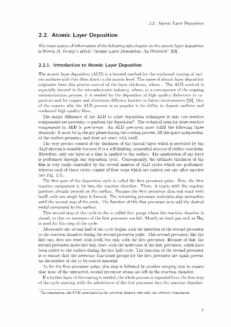
The atomic layer deposition (ALD) is a favored method for the conformal coating of vari-ous surfaces with thin �lms down to the atomic level. The name of atomic layer depositionoriginates from this precise control of the layer thickness, where . The ALD method isespecially favored in the microelectronic industry, where, as a consequence of the ongoingminiaturization process, it is needed for the deposition of high quality dielectrics to ca-pacitors and for copper and aluminum di�usion barriers in future interconnects [20]. Oneof the reasons why the ALD process is so popular is its ability to deposit uniform andconformal high quality �lms.The major di�erence of the ALD to other deposition techniques is that two reactive
components are necessary to perform the deposition2. The technical term for those reactivecomponents in ALD is precursors. An ALD precursor must ful�ll the following threedemands: It must be in the gas phase during the coating process, �ll the space independentof the surface geometry and does not react with itself.The very precise control of the thickness of the (metal) layer which is provided by the
ALD process is possible because it is a self-limiting, sequential process of surface reactions.Therefore, only one layer at a time is applied to the surface. The application of one layeris performed through one deposition cycle. Consequently, the ultimate thickness of the�lm is very easily controlled by the overall number of ALD cycles which are performed,whereas each of those cycles consist of four steps which are carried out one after another(see Fig. 2.5).The �rst part of the deposition cycle is called the �rst precursor pulse. Here, the �rst
reactive component is let into the reaction chamber. There, it reacts with the reactivepartners already present on the surface. Because the �rst precursor does not react withitself, only one single layer is formed. The remaining precursor molecules stay unreactiveuntil the second step of the cycle. The function of this �rst precursor is to add the desiredmetal compound to the surface.This second step of the cycle is the so called �rst purge where the reaction chamber is
rinsed, so that no remnants of the �rst precursor are left. Mostly an inert gas such as He2is used for this step of the cycle.Afterwards the second half of the cycle begins with the insertion of the second precursor
to the reaction chamber during the second precursor pulse. This second precursor, like the�rst one, does not react with itself, but only with the �rst precursor. Because of this, thesecond precursor molecules only react with the molecules of the �rst precursor, which havebeen added to the surface during the last half cycle. The function of the second precursoris to ensure that the necessary functional groups for the �rst precursor are again presenton the surface of the to be coated material.As for the �rst precursor pulse, this step is followed by another purging step to ensure
that none of the unreacted, second precursor atoms are left in the reaction chamber.If a further layer of the coating is needed, the whole process is repeated from the �rst step
of the cycle starting with the admittance of the �rst precursor into the reaction chamber.
2In comparison, the CVD mentioned in the previous chapter uses only one reactive component.
7

2. Carbon Nanotubes and the Atomic Layer Deposition
Figure 2.5.: Schema of the ALD process (modeled after [16])The ALD process starts from the upper left step with the �rst precursor pulse,
which is followed by the �rst purge and the subsequent second precursor pulse.
After another purging step the cycle starts again from the �rst precursor pulse.
One example for a speci�c ALD process is the Trimethylaluminum (TMA) atomic layerdeposition process, which will be explained in the following. In the scope of this thesis itwill be analyzed as a tool for the functionalization of CNTs.
2.2.2. Trimethylaluminum Atomic Layer Deposition
TMA is the �rst precursor in this process. Together with water as the second precursorthe ALD process can be described as shown in �gure 2.6 or in equations 2.5 and 2.6.
AlOH* + AL(CH3)3 → AlOAl(CH3)2* + CH4 (2.5)
AlCH3* + H2O→ AlOH* + CH4 (2.6)
where the asterisks denote the species on the surface for each part of the half cycle. Theoverall reaction enthalpy for the whole TMA cycle, as described in equation 2.7, is -376 kcal[13].
2Al(CH3)3 + 3H2O→ Al2O3 + 3CH4 (2.7)
The starting point of the TMA ALD process is the existence of hydroxyl groups on theto be coated surface. When TMA molecules are inserted into the reaction chamber, theyreact with the hydroxyl groups on the surface while methane is dissociated. There are twopossible types of aluminum-oxygen-bonding which can occur: either the aluminum atombonds with one oxygen atom resulting in dimethylaluminum oxide, or it reacts with twooxygen atoms forming methylaluminum oxide.After the �rst purging, which ensures that the unused TMA molecules, as well as the pro-
duced methane are cleaned out from the reaction chamber, water, as the second precursor,is admitted into the chamber. There, it reacts with the remaining methyl groups bound tothe aluminum atoms and results, under the dissociation of methane, in the bonding of new
8

2.2. Atomic Layer Deposition
Figure 2.6.: Schema of the TMA ALD (modeled after [6])Starting with the upper left picture, where hydroxyl atoms are already present at the initial
surface, the TMA ALD cycle starts with the inserting of the TMA molecules in the following
picture. After the �rst purge, water is inserted into the reaction chamber in the lower right
picture, before the chamber is purged again and the TMA ALD cycle starts again with the
upper middle picture.
hydroxyl groups to the aluminum atoms. After the second purge those hydroxyl groupsare the starting point for the deposition of another aluminum oxide layer, if desired.Of course, when this procedure is to be applied on CNTs, slight changes have to be
made, which will be discussed in 4.1.1. But before, it is necessary to deal with the theorybehind the research method of choice, namely Density Functional Theory.
9


3. Theoretical Background
The following chapter on the theoretical background of the Density Functional Theory(DFT) is based on Wolfram Koch and Max. C. Holthausen's book �A Chemist's Guide toDensity Functional Theory� [19].
3.1. The Schrödinger Equation and the Variational Principle
The foundation of the Density Functional Theory is the time-independent, non-relativisticSchrödinger equation:
HΨ = EΨ, (3.1)
whereas H is the Hamilton operator, which in atomic units is de�ned for a many bodyproblem with N electrons and M nuclei as:
H = −1
2
N∑i=1
∇2i−
1
2
M∑A=1
1
MA∇2
A −N∑i=1
M∑A=1
ZA
riA+
N∑i=1
N∑j>i
1
rij+
M∑A=1
M∑B>A
ZAZB
rAB(3.2)
The �rst two terms of the Hamilton operator (eq. 3.2) describe the kinetic energy ofthe electrons (presented by i, j running over the N electrons) and nuclei (presented byA, B running over the M nuclei) respectively. The remaining three terms contribute thepotential energy, while the third term takes the interaction between the electrons andthe nuclei into account. The last two terms represent the repulsion of the electrons andnuclei among themselves. Consequently, ZM is the charge of the nuclei, MA is the mass ofthe nuclei, and rxy represents the distance between electron-electron, electron-nucleus ornucleus-nucleus according to the indices.Solving the Schrödinger equation is for example possible with the use of con�guration
interaction methods. But for several atoms, this is far beyond any realization. For examplefor �a realspace representation of ψ on a mesh, in which each coordinate is discretized byusing 20 mesh points, for N electrons, ψ becomes a function of 3N coordinates (ignoringspin, and taking to be real), and 203N values are required to describe ψ on the mesh� [5].Therefore, several simpli�cations have to be taken into account.The Born-Oppenheimer approximation is used to simplify the Hamilton operator. In
this approximation the nuclei are regarded as static in comparison to the electrons. Thisis justi�ed because one proton has a mass of 1836 electrons and therefore, moves muchslower. This yields to the electronic Hamilton operator (eq. 3.3):
Helec = −1
2
N∑i=1
∇2i −
N∑i=1
M∑A=1
ZA
riA+
N∑i=1
N∑j>i
1
rij= Te + Ven + Vee, (3.3)
because the kinetic energy of the nuclei is zero under those conditions and the potential
11

3. Theoretical Background
energy from the nucleus-nucleus repulsion becomes a constant (3.4):
Enuc = Vnn =
M∑A=1
M∑B>A
ZAZB
rAB= const. (3.4)
Therefore, the total energy of the system can be described as:
Etot = Eelec + Enuc (3.5)
whereas Eelec can be gained by solving the electronic Schrödinger equation:
HelecΨelec = EelecΨelec (3.6)
But only for the one-electron system, an exact solution for eq. 3.6 exists. For morecomplex systems it is necessary to �rst adjust the (electronic) Hamilton operator to theinvestigated system. The second task is to �nd the eigenfunctions Ψi and the correspondingenergies Ei which are the eigenvalues of H. To receive the ground state energy E0 eq. 3.7must be solved, where E0 is the expectation value of the Hamilton operator:⟨
Ψ0|H|Ψ0
⟩= E0 (3.7)
Unfortunately, the correct wave function of the ground state, Ψ0, is unknown; insteadonly an approximated wave function Ψb is known, which will be described in detail in thefollowing chapter.
However, the Variational Principle states that the expectation value of the Hamiltonoperator with a test wave function is always higher than the absolute minimal energy, whichis the energy of the ground state. Therefore, independently from the regarded system onewill, because of the approximation and the use of approximated wave functions, alwaysreceive an energy which is higher than the real ground state energy (see eq. 3.8).⟨
Ψb|H|Ψb
⟩= Eb ≥ E0 (3.8)
Because of this, the accuracy of a method, which utilizes equation 3.7, can be classi�ed bythe energy one obtains. Namely, the method yielding the lowest energy is the best one,since it is closer to the exact solution.
3.2. Electron Density
3.2.1. The Wave Function Ψ
Before moving on to the electron density, it is necessary to take a closer look at thewave function Ψ. First of all, it is important to state that the wave function Ψ itselfis not observable; only its square has a physical meaning, since it can be interpreted asthe probability to �nd the electrons 1 to N contemporaneously in the volume elementsd ~x1d ~x2...d ~xN . Because of the indistinguishability of the electrons, the wave function Ψmust satisfy eq. 3.9:
|Ψ ( ~x1, ~x2, ..., ~xi, ..., ~xj , ..., ~xN ) |2 = |Ψ ( ~x1, ~x2, ..., ~xj , ..., ~xi, ..., ~xN ) |2 (3.9)
12

3.2. Electron Density
Furthermore, since electrons are fermions, their wave functions must be antisymmetric.Consequently the terms of eq. 3.9 can only be met if
Ψ ( ~x1, ~x2, ..., ~xi, ..., ~xj , ..., ~xN ) = −Ψ ( ~x1, ~x2, ..., ~xj , ..., ~xi, ..., ~xN ) (3.10)
applies for Ψ. Additionally if the integral of eq. 3.9 over the whole room equals 1, thenthe wave function is de�ned as normalized:ˆ
...
ˆ|Ψ ( ~x1, ~x2, ..., ~xi, ..., ~xj , ..., ~xN ) |2d ~x1d ~x2...d ~xN = 1 (3.11)
Because the Slater determinant ful�lls all those above mentioned conditions, it waschosen as the starting point for the construction of the approximated wave function Ψb sinceit allows to construct an approximated N -electron wave function based on one-electronwave functions, χi (~xi) (see eq. 3.12). This is necessary, since one-electron wave functionsare easier to handle. The requirements of eq. 3.9 and 3.10 are met by the natural propertyof the determinants where a permutation of two lines or columns leads to a change ofthe sign, but the square of the determinant stays untouched. The normalization of thewave functions occurs through the prefactor 1√
N !added to the determinate. In most cases,
instead of writing out the Slater determinant in full, one only comes across the diagonalentries (see eq. 3.12).
Ψb ≈ ΦSD = 1√N !
∣∣∣∣∣∣∣∣∣∣∣
χ1 ( ~x1) χ2 ( ~x1) . . . χN ( ~x1)χ1 ( ~x2) χ2 ( ~x2) . . . χN ( ~x2)
......
. . ....
χ1 ( ~xN ) χ2 ( ~xN ) · · · χN ( ~xN )
∣∣∣∣∣∣∣∣∣∣∣= 1√
N !det {χ1 ( ~x1) χ2 ( ~x2) . . . χN ( ~xN )}
(3.12)
The one-electron functions χi (~xi) in the Slater determinant are called spin orbitals, whichin turn are composed of one spin function (α(s) or β(s)) and one spatial orbital φi(~r):
χ (~x) = φ(~r)σ(s), σ = α, β (3.13)
3.2.2. The Electron Density ρ
The square of the wave function, as described in eq. 3.9, integrated over all electroncoordinates except of one spatial variable and multiplied by the number of electrons Nleads to the electron density:
ρ(~r) = N
ˆ. . .
ˆ|Ψ ( ~x1, ~x2, ..., ~xi, ..., ~xj , ..., ~xN ) |2ds1d ~x2 . . . d ~xN (3.14)
As can been seen in equation 3.14 above, this electron density describes the possibility to�nd N − 1 electrons with free choice of place and spin, while the one remaining electron isin the volume element d~r1 and only its spin is random.In contrast to the previously described wave function, the electron density is an physically
observable property of a system. For example it can be investigated by X-ray di�raction.Furthermore, the electron density ful�lls the following two properties: ρ (~r →∞) = 0 and
13

3. Theoretical Background
´ρ (~r) d~r1 = N . This means that the possibility to �nd an electron in�nitely afar from the
nucleus is zero and that the density integrated over the whole space results in the overallnumber of electrons.
3.3. The Hohenberg-Kohn Theorems
The Hohenberg-Kohn Theorems build the fundament of today's DFT. They were �rstproposed in the year 1964 [14]. Walter Kohn was rewarded with the Nobel prize in 1998for contributing in the development of DFT [24]. The characteristic of DFT is that itis a method which is a good mix between being fast, accurate and suitable for largermolecules. Those three factors are the reason why it was chosen for this thesis. Forexample the Coupled Cluster approach is more accurate, but it is not suitable for largerstructures, such as CNTs. The Hartree-Fock method on the other hand, is only a bit fasterthan DFT, while its energy is not as accurate as DFT.
3.3.1. The First Hohenberg-Kohn Theorem
The �rst Hohenberg-Kohn theorem proves that the electron density is su�cient to deter-mine H and consequently all properties of interest a system may have in its ground state.This assumption is proved by using the reductio ad absurdum scheme, where in this caseit is assumed that two di�erent external potentials, Vext(~r) and V ′ext(~r), di�er by morethan a constant1, still lead to the same density ρ(~r). This means that the accompanyingHamilton operators are identical except for their external potential terms:
H = T + Vee + Vext and H ′ = T + Vee + V ′ext (3.15)
As a consequence, those two Hamilton operators also have di�erent ground state wavefunctions Ψ and Ψ′, additionally to yielding to two ground state energies E0 and E′0,whereas E0 6= E′0. Nevertheless, it is assumed that they still lead to the same electrondensity, which is possible with respect to equation 3.14.Because Ψ and Ψ′ di�er, one can use Ψ′ as a trial wave function for H and vice versa.
Taking the variational principle into account this results (for using Ψ′ with H) in:
E0 <⟨
Ψ′|H|Ψ′⟩
=⟨
Ψ′|H ′|Ψ′⟩
+⟨
Ψ′|H − H ′|Ψ′⟩
(3.16)
Since, as stated in equation 3.15, H and H ′ only vary in their external potential, equation3.16 can be written as follows:
E0 < E′0 +⟨
Ψ′|T + Vee + Vext − T − Vee − V ′ext|Ψ′⟩
= E′0 +
ˆρ(~r)
{Vext − V ′ext
}d~r
(3.17)If now ψ is used as a trial wave function for H ′ this in analogy to the above yields to:
E′0 < E0 −ˆρ(~r)
{Vext − V ′ext
}d~r (3.18)
Adding equations 3.17 and 3.18 results to the contradiction:
E0 + E′0 < E0 + E′0, (3.19)
1Only if the potentials di�er by more than a constant do they lead to di�erent wave functions.
14

3.4. The Kohn-Sham Approach
which prove that, opposed to the previous assumption, two di�erent external potentialsVext(~r) and V ′ext(~r) do not lead to two di�erent electron densities, or conversely �that theground state electron density uniquely speci�es the external potential Vext� [19]. Thismeans that with ρ0 it is possible to de�ne H and therefore, obtain E0 and all otherproperties of interest of the system.Consequently, not only E0 but also its components can be de�ned by ρ0:
E0 [ρ0] = T [ρ0] + Eee [ρ0] + Ene [ρ0] (3.20)
With Ene =´ρ0(~r)Vne d~r and de�ning the universal2 terms as the Hohenberg-Kohn func-
tional FHK [ρ0] = T [ρ0] + Eee [ρ0] =⟨
Ψ|T + Vee|Ψ⟩one obtains:
E0 [ρ0] =
ˆρ0(~r)Vne d~r + FHK [ρ0] (3.21)
This means, that if FHK [ρ0] would be known, the Schrödinger equation could be solvedexactly. Unfortunately, the quest for �nding the de�nition of FHK [ρ0] is still going on.The only exactly known term for FHK [ρ0] is the classical Coulomb interaction part J [ρ0]of Eee [ρ0]:
Eee [ρ0] =1
2
ˆ ˆρ (~r1) ρ (~r2)
r12d~r1d~r2 + Encl [ρ] = J [ρ] + Encl [ρ] (3.22)
This means that besides the kinetic energy T [ρ] also the exact term for the non-classicalelectron-electron interaction Encl [ρ] is unknown. A method how these two componentscan be approximated as accurate as possible will be described later.
3.3.2. The Second Hohenberg-Kohn Theorem
The second Hohenberg-Kohn theorem ensures that the energy is only then the ground stateenergy if the ground state density was used to acquire the energy. This is accomplished bysimply utilizing the variational principle in analogy to its use in section 2.1, only that inthis case a trial density ρ is used as the starting point. This trial density ρ consequently
de�nes Ψ and its own ˜H and the gained Ψ is used with the real ground state Hamiltonoperator H, which leads to the following equation:⟨
Ψ0|H|Ψ0
⟩= E0 [ρ0] ≤ E [ρ] = T [ρ] + Vee [ρ] +
ˆρ (~r)Vext d~r =
⟨Ψ|H|Ψ
⟩(3.23)
This proves that only the ground state density ρ0 will yield to the ground state energy E0.
3.4. The Kohn-Sham Approach
The Kohn-Sham approach is based on an article [21] which was published one year afterthe Hohenberg-Kohn theorems. It concentrates on �nding a way how the unknown termsof the universal functional F [ρ] can be gained as exactly as possible.Based on orbital-based methods, like the Hartree-Fock method, Kohn and Sham sug-
gested the use of one-electron functionals ϕi to build a non-interacting reference system,in which the kinetic energy can be computed with good accuracy. The small part of the
2In the sense of being independent from N , rA and ZA.
15

3. Theoretical Background
kinetic energy which cannot be computed by this approach gets joined with the unknownnon-classical electron-electron contribution and becomes the new functional to be quested.This approach can be summarized in short with the three Kohn-Sham equations [5]:
ρS(~r)N
=∑i
fi|ϕi (~r, s) |2 = ρ0 (~r) (3.24)
fi =
1
0
0 ≤ fi ≤ 1
, for i < N
, for i > N
, for i = N
VS (~r) = Veff (~r) =
ˆρ (~r2)
r12d~r2 + VXC (~r1)−
M∑A
ZA
r1A(3.25)
fKSϕi = (−1
2∇2 + Veff (~r1))ϕi = εiϕi (3.26)
In short equation 3.24 states that the Sham density ρS , which is the sum of the Kohn-Sham orbitals ϕi of the reference system, leads to the ground state density of the real,investigated system. In equation 3.26 the Kohn-Sham operator fKS is de�ned, which leadsto the corresponding eigenenergy ε. Equation 3.25 de�nes the potential of the referencesystem VS , which is equal to the e�ective potential Veff .The �rst and last term of the e�ective Potential in eq. 3.25 are the Coulomb Potential
and the potential from the nuclei-electron interaction, respectively. The middle term isthe exchange-correlation potential VXC , which contains all the unknown terms from theHohenberg-Kohn functional FHK . Opposed to the Hohenberg-Kohn theorems, here, themajority of the kinetic energy T is known. This is made possible by dividing T in twoparts:
T [ρ] = Ts [ρ] + TC [ρ] = −1
2
N∑i
⟨ϕi|∇2|ϕi
⟩+ TC [ρ] (3.27)
The �rst term TS is the exact kinetic energy of the reference system and the unknown TCcontains the rather small di�erence of the kinetic energy of the reference system to the realsystem. This means that besides the potential corresponding to the non-classical energyEncl, VXC also contains the potential to the unknown part of the kinetic energy, TC .Consequently, nowadays the main subject of interest in DFT is to �nd the best approxi-
mation for the unknown exchange-correlation potential VXC , known as the DFT functional.Since an indeep discussion of the quest for the exchange-correlation functional would breakthe scope of this thesis, it is time to �nally have a look at the chosen model system for thesimulations, as well as at the chosen quantum chemical programs.
16

4. Computational Details and the Model
System
4.1. Model System
The model system of this thesis must ful�ll two demands: It should be computationallyconvenient in size, so that the computation time is low. Secondly, it should possess similarproperties as the CNTs which are used in experiments, so that a comparison with exper-imental works is possible. An example for such a comparison between the simulationshere and an experimental work would be the work of my colleague Marcel Melzer, whoperformed and investigated a copper ALD on CNTs within the framework of his Bachelorthesis [23].Those two demands in the end led to the chosen CNT model system, which will be
described in the following two sub-chapters.
4.1.1. The Basic (5, 5)-CNT
First of all, in experimental works mostly metallic multi-walled CNTs1 are investigated.Therefore, to ensure a comparability with experiments the basic CNT for this thesis shouldalso be metallic. In the case of single-walled CNTs this means that it must be an armchair(n, n)-CNT. In a previous study [12] it was shown, that the studied semiconducting CNThad been more reactive regarding the hydroxyl-functionalization than the analyzed metallicCNT. In detail this means that whereas for the semiconducting CNT all investigatedreactions were exothermic, the similar reactions were only occasionally exothermic whenperformed on a metallic CNT. The reason for this di�erence is believed to be caused bytheir di�erent electronic structures. Therefore, it is important that the CNTs have similarelectronic properties if a comparison between the experimental work and the simulation isto be made.Furthermore, the simulation demands that the studied CNT is small to keep down the
computation time, while at the same time it must be assured that the σ-π-hybridisationinside the tube is small, so that its in�uence is negligible. This means that the diameterof the CNT must be large enough. Thus, the metallic (5, 5)-CNT was chosen as the basis,since it ful�lls with a diameter of 6.78 Å [30] all of the so far stated demands.Next it had to be decided if a periodic or a cluster model of this CNT is to be used.
Previous calculations have shown that in regard to the calculated reaction energies, periodicsystems and the cluster models do not di�er greatly from each other [12]. However, theuse of a periodic system leads to a dramatic increase in computation time. Therefore, thecluster system was chosen for this work.For the cluster model it is important to saturate the ends of the CNT with hydrogen
atoms to avoid non-realistic interactions during the calculations. Those additional hydro-gen atoms do not in�uence the reaction energy, since as stated above, both the clustermodel and the periodic system yield the same reaction energies.
1The reason why in experiments multi-walled CNTs are used is that those are much easier to grow thansingle-walled CNTs.
17

4. Computational Details and the Model System
Additionally, the basic CNT needs to contain a SV defect because as mentioned in 2.1.3,this defect makes the CNT very reactive. This high reactivity is an essential requirement ofthe investigated system because the TMA ALD requires hydroxyl groups at the surface ofthe material. To achieve this, it must be possible to apply hydroxyl groups to the CNT bymeans of chemical reactions. Furthermore, it can be assured, as mentioned in 2.1.3, thatthe synthesized CNTs actually do contain those defects, as well as possibly topologicaldefects. Since previous investigations have shown that both the ideal CNTs and thosecontaining a SW defect are not reactive with water [12], they are not regarded as systemsof interest in this study.As a consequence of the basic CNT containing a SV defect, at least �ve unit cells of
the (5, 5)-CNT are required, so that the defect does not undesirably interact with theends of the CNT, as previous studies have shown [12]. This leads to an overall number ofninety-nine carbon atoms. It would have been possible to increase the number of carbonatoms forming the CNT2, however, because a larger system would also mean an increasein the computation time, it was decided against further enlarging the system. The reasonfor this is that the computation time is proportional to N3, where N is the number ofvalence electrons in the cluster model.In the end, all of the above mentioned factors result in the basic structure used through-
out the simulations, which is a metallic (5, 5)-CNT with the molecular formula C99H20,
which contains a Single Vacancy defect (Fig. 4.1) similar to the one described in [32].
Figure 4.1.: Cluster model of the basic (5, 5)-CNTThe basic (5,5)-CNT consists of ninety-nine carbon atoms and is saturated at
the ends by twenty hydrogen atoms. Additionally, it also contains a Single
Vacancy defect.
4.1.2. Further Adjustments to the Basic (5, 5)-CNT
As described in 2.2.2, the starting point of the TMA ALD are hydroxyl groups at thesurface of the material which one wishes to coat. To ful�ll this requirement the abovementioned basic (5, 5)-CNT needs to be further adjusted. This means that the studiedCNT must not only contain the SV defect, but also hydroxyl groups, which are bound tothe defect.
2The size of the CNT can only be increased by adding another unit cell of the chosen CNT. For the(5, 5)-CNT, which has a rather small unit cell, this means that another twenty carbon atoms wouldhave been added to the system, resulting in an overall number of 139 atoms in stead of the used 119.
18

4.1. Model System
This demand can be easily ful�lled because the SV defects is very reactive and theCNTs used in the experiments come in contact with both water and oxygen3 before theatomic layer deposition takes place. Therefore, it is justi�ed to assume that the CNTsused in the experiments indeed already have reacted with those two molecules. Based onthis assumption all dangling bonds of the carbon atoms of the SV defect are saturated.This ensures that the starting structures for the simulations are closed-shell systems witha de�ned modularity4.For the basic (5, 5)-CNT this means that all the studied educts must have reacted with
water and oxygen in a way that all four previously free electrons from the SV defect arenow saturated by either oxygen or hydrogen atoms or hydroxyl groups. Those possibleformations will be further discussed in 5.1.For a TMA ALD the CNT ideally should possess as many hydroxyl groups as possible.
Hence, the chosen educts for the study of the TMA ALD process are CNTs, where the basic(5, 5)-CNTs reacted with two water molecules and one oxygen molecule. Those reactionsresult in the creation of CNTs which contain four hydroxyl groups bound to four of thecarbon atoms of the SV defect. Additionally, it would be preferable if those four hydroxylgroups would be close and even form a band around the SV defect, so that a thin �lmcan be created in one area. Therefore, the two educts for the TMA ALD are CNTs whichpossess four hydroxyl groups bound to neighboring carbon atoms of the SV defect. Bothof the chosen educts, which will be presented in 5.1.4, ful�lled those demands (an exampleis shown in �g. 4.2).
Figure 4.2.: One of the educts for the study of the TMA ALD cycle
It is of course important to verify if the chosen educts for the study of the TMAALD cycleare energetically favorable, as the reaction energies of -81.82 kcal/mol and -71.61 kcal/molfrom the basic (5, 5)-CNT are only able to verify that the reaction is exothermic. Con-sequently, besides the TMA ALD process other possible saturated structures must bestudied, independently if the result in the possession of hydroxyl groups. Those possiblestructures will be presented and investigated in 5.1, because those other possible CNTfunctionalizations may have a higher possibility to be formed.The short time available for this work made it necessary that the study of the di�erent
possible educts and the simulation of the TMA ALD cycle had to be carried out con-temporaneously. Therefore, it had not been possible to �rst study the possible educts and
3In most experiments, the synthesized CNTs usually come in contact with air, which contains both oxygenand water, between the synthesis and the performance of the ALD.
4For a further explanation of the importance of the closed-shell system as the starting point see AppendixA.1.
19

4. Computational Details and the Model System
afterwards carry out the study of the TMA ALD cycle based on the insights gained throughthe study of possible educts. Still, independently whether the chosen educts turn out to beenergetically favorable or not, the results from those educts are descriptive for the TMAcycle in general, because the general reaction schemes of the TMA ALD are assumed tobe independent of the educt, as long as they contain hydroxyl groups.Though, before the di�erent functionalized CNTs can be discussed in detail, it is neces-
sary to take a closer look at the used quantum chemical programs �rst.
20

4.2. Computational Details
4.2. Computational Details
4.2.1. Materials Studio/Dmol³
For the present work Accelrys' Materials Studio (Version 6.0) [1] was the primarily usedquantum chemical software. It is a commercial software which includes the so calledMaterials visualizer, a graphical interface, as well as many di�erent quantum chemicalprograms such as CASTEP, ONETEP and Dmol³. One of the advantages of this softwareis that the Materials visualizer includes a module which automatically generates CNTsaccording to the chosen chirality. The images of the studied structures used throughoutthis work are created with the Materials visualizer.Dmol³ [8, 9] is a DFT program, which �uses fast convergent three-dimensional numerical
integrations to calculate the matrix elements occurring in the Ritz variation method�[8]and o�ers many di�erent LDA and GGA functionals as well as B3LYP.Because the number of calculations which can be performed simultaneously is limited by
the available licenses in Materials Studio (more details in section A.2), Dmol³ was solelyused for the simulation of the TMA ALD cycle in 5.2. For this study the CNTs generatedby Materials Studio were geometry optimized, while the following settings were used:The functional of choice was the GGA PBE functional proposed by Perdew, Burke and
Ernzerhof [28]. It was applied together with the DNP5 basis set [8]. This combinationwas used for all calculations because, according to [10], its accuracy is close to that of theB3LYP functional with the 6-31G** basis set, while the numerical e�ort is lower.The setting of the global orbital cuto� was changed to a value of 4.8 Å for the smaller
molecules, like methane. This is necessary to ensure that the same value is used for eachcalculation. This value is normally adapted automatically, depending on the system'ssize, and has a minor, but non-negligible, in�uence on the total energy of the system.Furthermore, the DIIS option, which is a way to average out �uctuations in the densitymatrix by mixing small parts of the densities from previous steps with the current density,was used with a value of 6.Sometimes it is necessary to use the thermal smearing option Dmol³ provides because
a geometry optimization would not converge elsewise. The smearing was limited to amaximum value of 0.01 Ha (about the energy of a particle at room temperature), which isa good compromise between gaining an optimal structure and slightly falsi�ed results. The�nal result is not changed, because after the geometry optimization an energy calculationtogether with a frequency analysis is carried out, while the smearing option is turned o�and the other settings stay identical.For all other parameters the default setting '�ne' was used, whose details are summa-
rized in table 4.1.
4.2.2. Turbomole
Turbomole [2] is, like Materials Studio, a quantum chemical program, which was �rstimplemented by Prof. Ahlrichs together with various students and postdoctoral researchersat the University of Karlsruhe and at the Forschungszentrum Karlsruhe [35]. Nowadaysit has developed into a company, where its features are still improved. Turbomole o�ersdi�erent quantum chemical methods such as Hartree-Fock, MP2 and DFT. Because the
5Double numerical plus polarization. This means that for each occupied atomic valence orbital, a secondset of atomic orbitals is assigned. Furthermore, for all hydrogen atoms a polarization p-function isincluded.
21

4. Computational Details and the Model System
Quantum-Chemical Program Materials Studio Turbomole
Basis set DNP 3.5 def2-TZVPFunctional PBE BP86
SCF-convergence 10−6 10−6
Charge 0 0Symmetry no symmetry no symmetry
DIIS 6 -Orbital cuto� value 4.8 Å -
Maximal smearing value 0.01 Ha -Ri option - on
Table 4.1.: Overview of the Computational DetailsFor a better comprehensibility all the used speci�c settings together with the most
important default settings are summarized in this table for both quantum-chemical
programs.
number of calculations which can be performed simultaneously is only limited by theavailable computational resources and not by license (more details in section A.2), it wasused for the study of the educts in 5.1.The starting point of the DFT-calculations carried out with Turbomole (Version 6.3.1)
are structures, which were generated by Materials Studio, exported and then geometryoptimized with the speci�c settings listed in table 4.1.Instead of using the GGA PBE functional, which leads to problems with Turbomole6,
the BP86-functional [3, 11, 27, 33, 37] was used instead, which yields the same accuracyas PBE (see Appendix A.3).Furthermore, the available basis sets of Dmol³ and Turbomole di�er because Dmol³ uses
numerical basis sets while Turbomole uses gaussian basis sets. Consequently, the numericalDNP basis set from Dmol³ is not available for Turbomole. For this work the 'def2-TZVP'7
basis set [39] was chosen for the calculations, which is large enough to ensure that theresults can be regarded as qualitatively and quantitatively correct8 within a reasonablecomputation time and has about the same accuracy as the DNP basis set (see AppendixA.3).After the geometry optimization a frequency analysis with the aoforce module was carried
out.To speed up the calculation, the ri approximation was used. Ri stands for 'resolution
of identity' which is a mathematical trick, which reduces �expensive four-center integralsinto a combination of two three-center integrals through the introduction of the auxiliarybasis set �[19]. This reduces the calculation time immensely since three-center integralsare faster to calculate than four-center integrals. Nevertheless, it still is an additionalapproximation to accept, but the speed up of the calculation time by a factor of about tenjusti�es this rather small error of under 1 kcal/mol. Especially, since the ri approximationcauses a systematic shift in the energy, which is mostly resolved during the calculationof the reaction energies. The auxiliary basis set used for the ri approximation was alsodef2-TZVP [38].
6The use of the PBE functional in Turbomole for CNTs lead to a very high increase in the computationtime or the calculation are not carried out at all due to numerical problems.
7Triple Zeta Valence plus Polarization. This means that three Slater-type valence orbitals are usedtogether with one polarization p-function for each occupied atomic orbital.
8This basis set is necessary for accurate SCF or DFT [36].
22

4.2. Computational Details
Besides increasing the number of scf-cycles to a higher value � if necessary � the standardparameters remain unchanged.
23


5. Results and Discussion
The focus of this thesis lies on two major aspects of a possible CNT-functionalization witha TMA ALD. The �rst studied aspect is the analysis of a TMA ALD performed on twoselected starting structures. This study requires that the used educts are compared withother possible educts to verify if they are energetically favorable. Therefore, the secondstudied aspect is the analysis of di�erent structures which could be found after the basic(5, 5)-CNT is exposed to air.To make the interpretation of the results more comfortable and more descriptive, they
are presented in the form of diagrams and schemata. A listing of the resulting energies ofthe structures, as well as the reaction energies can be found in the Appendix A.4 for thepossible educt formations and in Appendix A.5 for the analysis of the TMA ALD cycle.
5.1. Educt Formation Reactions1
For the present work, (5, 5)-CNTs which have reacted with the oxygen and/or water in theair were taken into consideration (see section 4.1). The studied educts are divided into �vegroups, based on their functional groups: The educts with two oxygen atoms, the eductswith two hydroxyl groups and one oxygen atom, the educts with two hydroxyl groups andtwo hydrogen atoms, the educts with four hydroxyl groups and the educts with peroxygroups.The reason why also educts which do not possess the necessary hydroxyl groups for the
TMA ALD are analyzed is that oxygen is believed to be more reactive than water. Thus, itis probable that those species may be dominant to the other educts which contain hydroxylgroups. The order of the �ve educt groups is based on this assumption that oxygen is farmore reactive than water. Therefore, the aim is to �nd educts which possess hydroxylgroups while on the same time they are energetically more favorable than the educts whichonly contain oxygen.One of the aims is to analyze how the di�erent functional groups a�ect the energy of
the CNT, while at the same time the in�uence of the position of the functional groups canbe studied. For this purpose the carbon atoms of the SV defect are labeled as shown in�gure 5.1.In order to analyze in detail how the functional groups and their positions in�uence
the energy of the structure, , one of the functional groups remains bound to carbon atom2, while the rest of the functional groups shift their positions within the labeled carbonatoms of the SV defect. The reason why carbon atom number 2 was chosen as the mostfrequented bonding partner for the functional groups is, as previous studies have shown[12], the high reactivity of this carbon atom due to its two dangling bonds.To simplify the dependency of the energy on the functional groups and their positions
the concept of the correspondence number x as part of the structures' names is established.This correspondence number x determines the carbon atoms of the SV defect to which thedi�erent functional groups can bind (see table 5.1). This means that the functional groups
1For additional information on the structures please refer to the accompanied CD, where the xyz-�lescan be found together with further pictures.
25

5. Results and Discussion
Figure 5.1.: The labeled carbon atoms of the Single Vacancy defect.This fragment of the studied (5, 5)-CNT only shows the carbon atoms used as
bonding partners for the functional groups, which are labeled and highlighted
in green. The carbon atom number 2 is the only atom of the SV defect, which
possesses two dangling bonds.
of structures with the same correspondence number x occupy the same positions. Forexample the correspondence number x=1 indicates that the functional groups are alwaysbound to the carbon atoms 2, 6 and 7.
correspondence number xcarbon atoms to which
the functional groups bond
1 2, 6 and 72 2, 6, 8 and 93 2, 8 and 94 2, 5, 6 and 75 1, 2 and 96 2, 7 and 87 2, 5 and 68 2, 3 and 49 2, 4 and 5
Table 5.1.: Overview of the correspondence number x
To ensure the comparability of the reaction energies from all the di�erent groups ofeducts, the reaction energies are all based on one of the studied educt. The reason whythe reaction energy has to be based on one of the educts is that the basic (5, 5)-CNT is anopen-shell system and therefore, is unsuitable for this purpose (see Appendix A.1). The�rst educt of the �rst studied group of educts (see 5.1.1) had been chosen as the referencepoint, because it is the predominant species out of this �rst studied group.To be able to classify the following reaction energies, the reaction energy from the basic
(5, 5)-CNT with oxygen resulting into the �rst educt was determined. The reaction energyamounts to -165.32 kcal/mol and therefore, the reaction is highly exothermic, indepen-dently of the multiplicity of the basic (5, 5)-CNT.This study of the educts is carried out with Turbomole only, after an initial structure
had been created in Materials Studio.
26

5.1. Educt Formation Reactions
5.1.1. Educts with Two Oxygen Atoms
The starting point for the study of the educts are saturated CNTs which are the productsof reactions of the basic (5, 5)-CNT with O2:
CNT +O2 → O = CNT = O (5.1)
Their structures are shown in �gure 5.3. Those structures were chosen as the startingpoint, because it is assumed that oxygen is more reactive than water.The educts have the following naming scheme: 1_O2_x, where x is the correspondence
number and 1_O2 indicates that it is an educt from the reaction of the basic CNT withone O2.The reaction energy of this group is attained by solving:
ER = E1_O2_x − E1_O2_1 (5.2)
and can be found in the diagram (�g. 5.2), as well as in �gure 5.3, where 1_O2_1 takesa central place as it is the educt on which all the reaction energies are based upon.
1_O2_1 1_O2_2 1_O2_3 1_O2_4 1_O2_5 1_O2_6 1_O2_7 1_O2_8 1_O2_90.00
10.00
20.00
30.00
40.00
50.00
60.00
70.00
80.00
90.00
100.00
Reaction energy ~ of 1_O2_x based on 1_O2_1 ~
Reaction energy for 1_O2_x
Educt
Rea
ctio
n en
ergy
in k
cal/m
ol
Figure 5.2.: The reaction energy for the educts 1_O2_x based on 1_O2_1The dots connecting the energy are only shown as a guide for the eyes.
As can be seen in �gure 5.2, all the reaction energies are endothermic for x6=1. Thismeans that all educts from the 1_O2_x group are energetically higher than 1_O2_1 byat least 40 kcal/mol, with 1_O2_4 possessing the highest reaction energy with a value of91.26 kcal/mol. Therefore, it can be assumed that 1_O2_1 is the dominant species outof the studied educts in this group.A reason for this could be that in the case of 1_O2_1 one of the two oxygen atoms
27

5. Results and Discussion
Overview
of the educts with tw
o oxygen atoms
48.28 kcal/mol
1_O2 _2
1_O2 _5
1_O2 _6
1_O2 _7
1_O2 _1
90.87 kcal/mol
88.61 kcal/mol
91.26 kcal/mol
54.42 kcal/mol
39.46
kcal/mol
59.50 kcal/mol
1_O2 _9
1_O2 _8
1_O2 _4
1_O2 _3
42.00 kcal/mol
Figure
5.3.:Overview
ofthe
eductswith
twooxygen
atoms(1_O2 _
x)
Inthis
schem
afra
gments
ofthestu
died
educts
from
thegro
upwith
twooxygen
atomsare
shown.Therea
ctionenergies
were
calcu
lated
acco
rdingto
equatio
n5.2
andare
noted
ontherespective
arro
ws.
28
5.1. Educt Formation Reactions
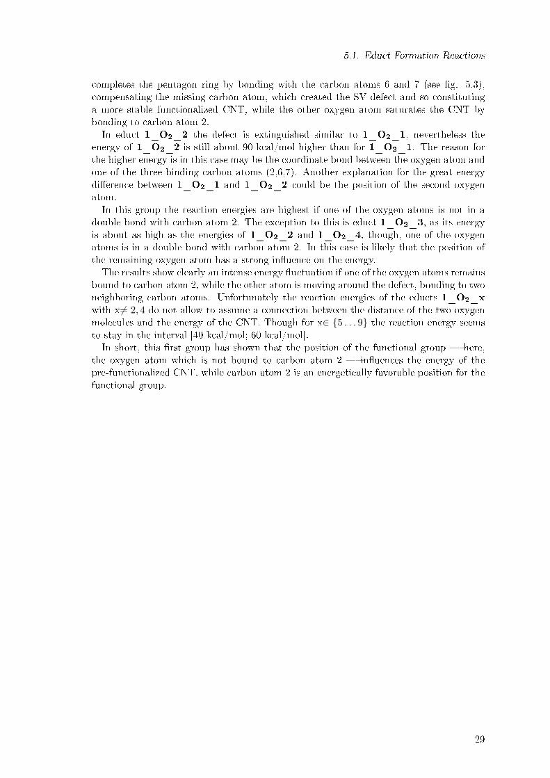
completes the pentagon ring by bonding with the carbon atoms 6 and 7 (see �g. 5.3),compensating the missing carbon atom, which created the SV defect and so constitutinga more stable functionalized CNT, while the other oxygen atom saturates the CNT bybonding to carbon atom 2.In educt 1_O2_2 the defect is extinguished similar to 1_O2_1, nevertheless the
energy of 1_O2_2 is still about 90 kcal/mol higher than for 1_O2_1. The reason forthe higher energy is in this case may be the coordinate bond between the oxygen atom andone of the three binding carbon atoms (2,6,7). Another explanation for the great energydi�erence between 1_O2_1 and 1_O2_2 could be the position of the second oxygenatom.In this group the reaction energies are highest if one of the oxygen atoms is not in a
double bond with carbon atom 2. The exception to this is educt 1_O2_3, as its energyis about as high as the energies of 1_O2_2 and 1_O2_4, though, one of the oxygenatoms is in a double bond with carbon atom 2. In this case is likely that the position ofthe remaining oxygen atom has a strong in�uence on the energy.The results show clearly an intense energy �uctuation if one of the oxygen atoms remains
bound to carbon atom 2, while the other atom is moving around the defect, bonding to twoneighboring carbon atoms. Unfortunately the reaction energies of the educts 1_O2_xwith x 6= 2, 4 do not allow to assume a connection between the distance of the two oxygenmolecules and the energy of the CNT. Though for x∈ {5 . . . 9} the reaction energy seemsto stay in the interval [40 kcal/mol; 60 kcal/mol].In short, this �rst group has shown that the position of the functional group � here,
the oxygen atom which is not bound to carbon atom 2 � in�uences the energy of thepre-functionalized CNT, while carbon atom 2 is an energetically favorable position for thefunctional group.
29

5. Results and Discussion
5.1.2. Educts with Two Hydroxyl Groups and One Oxygen Atom
The second step of functionalization is to analyze if it is possible to substitute one of theoxygen atoms with two hydroxyl groups. For this the reaction of the previously studiededucts with water resulting in the existence of two hydroxyl groups bound to the defectivesite of the CNT in addition to one oxygen atom:
O = CNT = O +H2O → (OH)2 − CNT = O (5.3)
The structures of those studied educts are shown in �gure 5.5.The naming scheme for those educt is the following: 1_H2O_x, where x is the corre-
spondence number and 1_H2O indicates that it is an educt from the reaction of the basicCNT with one oxygen molecule and one water molecule. To shorten the name only theone water molecule is used as a part of the naming scheme.The reaction energy is attained by solving:
ER = E1_H2O_x − E1_O2_1 − EH2O (5.4)
where EH2O is the energy of water2.The resulting reaction energies obtained from this equation are shown in the following
diagram (�g. 5.4) and in �gure 5.5.
1_H2O_1 1_H2O_2 1_H2O_3 1_H2O_4 1_H2O_5 1_H2O_6 1_H2O_7 1_H2O_8 1_H2O_9 1_O2_10.00
10.00
20.00
30.00
40.00
50.00
60.00
70.00
80.00
90.00
100.00
Reaction energy~ of 1_H2O_x based on 1_O2_1 ~
Reaction energy for 1_H2O_x
Educt
Rea
ctio
n en
ergy
in k
cal/m
ol
Figure 5.4.: The reaction energy for the educts 1_H2O_x based on 1_O2_1The value for 1_O2_1 is included in the far right of this diagram to indicate
that the reaction energies for this group were gained based on 1_O2_x. The
dots connecting the energy are only shown as a guide for the eyes.
2EH2O =-76.467 Ha
30

5.1. Educt Formation Reactions
Ove
rvie
w o
f the
edu
cts
with
two
hydr
oxyl
gro
ups
and
one
oxyg
en a
tom
32.04
kcal/
mol
1_H
2O_1
1_H
2O_4
1_H
2O_5
1_H
2O_6
1_O
2_1
21.10
kcal/
mol
78.1
9 kc
al/m
ol
73.3
3 kc
al/m
ol
86.88 kc
al/mol
5
0.64
kcal/mol
42.8
5 kc
al/m
ol
1_H
2O_8
1_H
2O_7
1_H
2O_3
1_H
2O_2
50.7
2 kc
al/m
ol
84.5
6 kc
al/m
ol
1_H
2O_9
Figure5.5.:Overviewof
theeducts
withtwohydroxyl
groups
andoneoxygen
atom
(1_H2O_x)
Inthisschem
afragm
entsofthestudiedeductsfrom
thegroupwithtwohydroxylgroupsandoneoxygenatom
are
shown.
Thereactionenergies
werecalculatedaccordingto
equation5.4
andare
notedontherespective
arrows.
Forabetter
comprehensibility
thewatermoleculecontributingto
thetotalenergy
of1_O2_1isnotshown.
31

5. Results and Discussion
As can be seen in �gure 5.4, when water is adsorbed to the previous structures, the reac-tion energies are again endothermic. The �uctuation interval is increased from 50 kcal/molto 70 kcal/mol. Those exothermic reaction energies mean that it would not be possiblefor water to react with a CNT, so that two hydroxyl groups are created when already twooxygen atoms were present on the CNT.If one considers that the positions of the functional groups in 1_H2O_1 are identical
to the ones in 1_O2_1 it is not surprising that it has the lowest reaction energy out ofthis group of educts. On the other hand, the same correlation between the position of thefunctional groups are not the case for x=9. While the corresponding structure 1_O2_9is one of the energetically lowest educts of the group containing two oxygen atoms, itscounterpart here has one of the highest reaction energies. Therefore, not the position ofthe functional group, but the functional group itself is the reason for the energy di�erence.This strong in�uence of the functional group seems to be an exception since there is
a general correlation between the �rst and the second group of educts according to thecorresponding number. For example as before 1_H2O_4 has the highest reaction energywith a value of 86.88 kcal/mol, followed by 1_H2O_9 and 1_H2O_2. Again the twostructures whose oxygen atoms are not in a double bond with carbon atom 2 are amongone of the energetically highest structures.In short, this group has shown that the exchange of one oxygen atom with two hydroxyl
groups leads in most cases to a slight change in the reaction energy only. One the sametime, the position of the functional groups still is the major in�uence to the energy of thedi�erent structures, with carbon atom 2 being the favorable bonding partner.
32

5.1. Educt Formation Reactions
5.1.3. Educts with Two Hydroxyl Groups and Two Hydrogen Atoms
The third group of educts are CNTs which are only functionalized with water (see eq.5.5). Those structures were taken into consideration to see if the CNT only reacts withwater, if the resulting structures are can compete with the CNTs who only have reactedwith oxygen. The structures of this group possess two hydroxyl groups and two hydrogenatoms.
CNT + 2H2O → (H)2 − CNT − (OH)2 (5.5)
Because the basic (5, 5)-CNT is an open-shell system, here, only the energy where waterreplaced the oxygen completely from 1_O2_1 can be studied (see eq. 5.6):
O = CNT = O + 2H2O → (H)2 − CNT − (OH)2 +O2 (5.6)
The structures of those educts are shown in �gure 5.6.The naming scheme for those educts is the following: 2_H2O_x, where x is the corre-
sponding number and 2_H2O indicates that it is an educt from the reaction of the basicCNT with two water molecules (eq. 5.5).The reaction energy can be attained according to the reaction scheme in eq. 5.6 by
solving:ER = E2_H2O_x + EO2 − E1_O2_1 − 2 ∗ EH2O (5.7)
where EO2 is the energy of an oxygen molecule3.The resulting reaction energies are shown in the following diagram (�g. 5.7) and in �gure
5.6.In comparison to the previously studied groups of educts, the interval of the reaction
energy lies within a span of 110-165 kcal/mol, which is much higher than in the previousgroups. This means that after the basic CNT has formed with an oxygen molecule one ofthe structures in 5.1.1, the probability of water eliminating the oxygen is zero.Furthermore, opposed to the two previous groups, it is not possible to draw any conclu-
sions regarding the correlation between the energy and the structure for those functionalgroups. For example both 2_H2O_1 and 2_H2O_2 show an expansion of the SV de-fect because the connection between carbon atom 6 and 7 is broken. Nevertheless, theenergy di�erence between those two structures amounts to 50 kcal/mol, so there seems tobe no relation between an expansion of the defective area and the energy.Opposed to the previous two groups, the in�uence of the functional groups is stronger
than in�uence the positions of the functional groups has. This not only shown by theincreased reaction energy this group exhibits, but also in the form of the previously favor-able position of the functional groups bound to carbon atom 2. Whereas 2_H2O_1 and2_H2O_8 have one of the lowest energies, 2_H2O_3 and 2_H2O_9 possess one ofthe highest energies in this group, though all four structures have two functional groupsbound to carbon atom 2. This new trend is supported by 2_H2O_2 and 2_H2O_4,where only either a hydrogen atom or a hydroxyl group is bound to carbon atom 2 andthe energy di�erence between those two structures amounts to 40 kcal/mol.In short, in this group the in�uence of the functional groups themselves are stronger
than the in�uence the position of the functional groups have. Nevertheless, the positionsof the functional groups still in�uence the energy of the structures.After the study of this group it is possible to draw some conclusions with respect to the
corresponding structures. For this, the reaction energies of all the so far studied educts are
3EO2= -150.409 Ha
33

5. Results and Discussion
2_H2 O
_1
2_H2 O
_42_H
2 O_5
2_H2 O
_6
1_O2 _1
111.62 kcal/mol
161.80 kcal/mol
151.59 kcal/mol118.65 kcal/mol
130.01
kcal/mol
117.18 kcal/mol
2_H2 O
_8
2_H2 O
_7
2_H2 O
_3
2_H2 O
_2
121.22 kcal/mol
165.69kcal/m
ol 2_H2 O
_9
110.09 kcal/mol
Overview
of the educts with tw
o hydroxyl groups and two hydrogen atom
s
Figure
5.6.:Overview
ofthe
eductswith
twohydroxyl
groupsand
twohydrogen
atoms(2_H2 O
_x)
Inthis
schem
afra
gments
ofthestu
died
educts
from
thegro
upwith
twohydroxyl
groupsandtwohydrogen
atomsare
shown.Therea
ctionenergies
were
calcu
lated
acco
rdingto
equatio
n5.7
andare
noted
ontherespective
arro
ws.
Fora
bettercompreh
ensibility
thewater
molecu
lesandtheoxygen
molecu
le,contribu
tingto
thetotalenergy
of1_O2_1and
2_H2 O
_xrespectively
are
notshown.
34

5.1. Educt Formation Reactions
2_H2O_1 2_H2O_2 2_H2O_3 2_H2O_4 2_H2O_5 2_H2O_6 2_H2O_7 2_H2O_8 2_H2O_9 1_O2_10.00
20.00
40.00
60.00
80.00
100.00
120.00
140.00
160.00
180.00
Reaction energy~ of 2_H2O_x based on 1_O2_1
Reaction energy for 2_H2O_x
Educt
Rea
ctio
n en
ergy
in k
cal/m
ol
Figure 5.7.: The reaction energy for the educts 2_H2O_x based on 1_O2_1The value for 1_O2_1 is included in the far right of this diagram to indicate
that the reaction energies for this group were gained based on 1_O2_x. The
dots connecting the energy are only shown as a guide for the eyes.
shown in �gure 5.8.The �rst conclusion is that for x= 1, 6, 8) the energy of the studied educts is one of the
lowest, independent of the functional group. This means that those three positions areenergetically favorable regardless of the functional groups which were added to the basicCNT.The second conclusion is that for x= 2, 3 the reaction energy of the studied educts is
one of the highest, regardless of the functional group. Therefore, those two positions areenergetically unfavorable in regard to positioning functional groups there.The �nal conclusion in regard to the corresponding structures is that the in�uence of
the functional groups is higher than the in�uence their position has. This e�ect of thefunctional groups on the energy can be seen for x= 4, 9. For example for x=9 the reactionenergy is one of the lowest when the oxygen atoms are bound to the carbon atoms 2 and4, whereas if at least one hydroxyl group is bound to one of them, this formation becomeson of the energetically highest educts of the group.In short, the in�uence a functional group has on a given position is not predictable a
priori. Reliable predictions can only be based on electronic structure calculations.
35

5. Results and Discussion
1 2 3 4 5 6 7 8 90.00
20.00
40.00
60.00
80.00
100.00
120.00
140.00
160.00
180.00
Overview of the reaction energies~ for the three educt groups with a corresponding number ~
Reaction energy for 1_O2_x
Reaction energy for 1_H2O_x
Reaction energy for 2_H2O_x
Corresponding number x
Rea
ctio
n en
ergy
Figure 5.8.: Overview of the reaction energies of the three educt groups with a correspon-dence number x: 1_H2O_x, 2_H2O_x and 1_O2_x
The structures on the right side show fragments of the structures with the cor-
respondence number x=1.
36

5.1. Educt Formation Reactions
5.1.4. Educts with Four Hydroxyl Groups
The fourth group of educts includes structures which can be gained by the reaction of twowater molecules and one oxygen molecule with the basic CNT resulting in four additionalhydroxyl groups at the SV defect:
CNT +O2 + 2H2O → CNT − (OH)4 (5.8)
This reaction is in competition with the one from 5.1.3 and was included for two reason.Firstly, because the educts for the study of the TMA ALD cycle are created through thisequation. Ans secondly, because it may be energetically more favorable if the water reactswith the oxygen atoms instead of displacing them from the CNT. The structures of thisgroup are shown in �gure 5.9.Contrary to the previous three groups, here, a correspondence number cannot be in-
cluded. As the structures were chosen by other criteria such as forming a band of hydroxylgroups on the defect, a uniform naming scheme does not exist for this group. Still, thisgroup can be divided into three sub-groups according to which the structures are named:
A) Selected structures from 5.1.2 reacted with a further water molecule without replacingthe oxygen as it had been the case in 5.1.3. The structures are named 1_H2O_x_B,where 1_H2O_x indicates the corresponding structure from 5.1.2 and the B indicatesthat another water atom was added to the CNT.B) Educts which are the starting point of the TMA cycle in 5.2 and possess a band of
hydroxyl groups. Therefore, their names are Educt_x, where x indicates the variation ofthe educt chosen for the study of the TMA cycle.C) Three reactions of the 1_O2_1 educt from 5.1.1 which resulted in educts with four
hydroxyl groups. Those educts where chosen, because 1_O2_1 so far has the lowestenergy. They are named 1_O2_1_y, where y stands for the variation of the reactionand 1_O2_1 refers to the basis of those variations. For y=A,B a Michael Addition hadtaken place, whereas for y=C, the four hydroxyl groups only are bound to the same carbonatoms as the functional groups of 1_O2_1
The reaction energy can be attained by solving:
ER = E4_OH − E1_O2_1 − 2 ∗ EH2O (5.9)
with E4_OH standing for the energy of the educts with four hydroxyl groups. The resultingreaction energies are shown in the following diagram (�g. 5.10), as well as in �gure 5.9.As can be seen in �gure 5.10, this group of educts possesses the highest reaction en-
ergy �uctuation so far with a value of over 115 kcal/mol. It is especially surprising that1_H2O_2_B has the lowest energy considering that in the previous three groups thestructure with the correspondence number x=2 always had been among the structureswith the highest reaction energies. The reason for the change of energy is that during thegeometry optimization, one of the hydroxyl groups is bound to carbon atom 7 instead of6. Though, in the �rst 2 groups, the structure with the correspondence number x=2 hadbeen bound to carbon atoms 6 and 7. Therefore, this structure can still be belongs to thegroup of structures with the correspondence number x=2.Within this group, Educt_1 and Educt_2, which are chosen as the educts for the
study of the TMA process on a CNT, occupy a reaction energy sector which is neitherthe highest nor the lowest. Though, if one takes into consideration that 1_O2_1_Cdoes not possess four hydroxyl groups any more after the geometry optimization (see �g.
37

5. Results and Discussion
Overview
of the educts with four hydroxyl groups
1_H2 O
_2_B
Educt_21_O
2 _1_A
1_O2 _1
45.64 kcal/mol
66.32 kcal/mol
80.42 kcal/mol
90.69 kcal/m
ol
54.49 kcal/mol
1_O2 _1_C
1_O2 _1_B
Educt_1
1_H2 O
_4_B
159.94 kcal/mol
55.50 kcal/mol
Figure
5.9.:Overview
ofthe
eductswith
fourhydroxyl
groupsIn
thissch
emafra
gmentsofthestu
died
educts
from
thegro
upwith
fourhydroxyl
groupsare
shown.Therea
ctionenergies
were
calcu
lated
acco
rdingto
equatio
n5.6
andare
noted
ontherespective
arro
ws.
Forabetter
compreh
ensibility
thewater
molecu
les,contribu
tingto
thetotalenergy
of1_O2_1are
notshown.
38

5.1. Educt Formation Reactions
1_H2O_2_B 1_H2O_4_B Educt_1 Educt_2 1_O2_1_A 1_O2_1_B 1_O2_1_C 1_O2_10.00
20.00
40.00
60.00
80.00
100.00
120.00
140.00
160.00
180.00
Reaction energy
~ of the educts with four hydroxyl groups based on 1_O2_1 ~
Reaction energy for educts with four hydroxyl groups
Educts
Rea
ctio
n en
ergy
in k
cal/m
ol
Figure 5.10.: The reaction energy for the educts with four hydroxyl groups based on1_O2_1
The value for 1_O2_1 is included in the far right of this diagram to indicate
that the reaction energies for this group were gained based on 1_O2_x. The
dots connecting the energy are only shown as a guide for the eyes.
5.9), the two chosen educts for the study of the TMA ALD are indeed the two mostunfavorable structures out of this group. This means that under the current circumstancesthe likelihood that one �nds the two educt structures for the study of the TMA ALD in5.2 � Educt_1 and Educt_2 � among the CNTs used for experiments is low. Still,1_H2O_2_B indicates that the criterion that the educts for the study of the TMA ALDshould possess a hydroxyl band, was not completely misplaced, as this structure possessesa hydroxyl band (consisting of three hydroxyl groups) and at the same time has the lowestenergy.With the results available now, it is clear that di�erent structures, like 1_O2_1_A or
1_H2O_2_B, would have been a better choice for the starting point of the TMA ALDstudy, especially since even the energetically lowest structure of this group still is energywise over 45 kcal/mol higher than 1_O2_1 and are therefore unlikely to be present in asample of CNTs within an experiment. Though, considering the great �uctuation in thereaction energies, it is possible that one may �nd CNTs which do posses four hydroxylgroups, if an energetically more favorable position for the hydroxyl groups is found. Thecurrent results do not allow to draw any conclusions, which positions would be morefavorable. Both forming a band of hydroxyl groups (1_H2O_2_B), as well as a onlyoccupying every second carbon atom of the defect (1_O2_1_A ) seem to be energeticallypreferable structures.In short, the study of this structure has shown that the educts for the study of the
39

5. Results and Discussion
TMA ALD, which were chosen at the beginning of this work, are energetically unfavorablestructures and that more favorable structures with four hydroxyl groups exist. Still, allthe so far studied structures which contain hydroxyl groups are energetically unfavorablecompared to 1_O2_1.
40

5.1. Educt Formation Reactions
5.1.5. Educts with Peroxy Groups
The last group of the studied educts are CNTs which at least possess one peroxy group asa functional group. These educts with peroxy groups were included, because so far oxygenhad been more reactive than water. Therefore, it would stand to reason that educts peroxygroups may be energetically even more favorable than oxygen groups. The naming schemeof this group goes as follows: 2_O2_y, where 2_O2 states that the educts of this grouppossess as least one peroxy group, y indicates the index of the variation. For y=1, thestructures has two peroxy groups, while for y=2,3 the structure has only one peroxy group.The reaction schemes are as follows:
O = CNT = O +O2 → CNT − (O −O)2 (5.10)
O = CNT = O +H2O →
H�
(O −O)− CNT�OH
+O2 (5.11)
The structures of the educts is shown in �gure 5.12.For this group of educts the reaction energy was attained by solving the following equa-
tions according to y:ER = E2_O2_1 − E1_O2_1 − EO2 (5.12)
ER = E1_O2_2/3 − E1_O2_1 − EH2O (5.13)
The resulting reaction energies are shown in the following diagram (�g. 5.11) and in �gure5.12.As one can see in �gure 5.11, there are only three di�erent structures which possess
a peroxy group. The time frame of this work did not allow to study more possibilities.Nevertheless, the available results still give some insight to this group.On the one hand they show that the number of peroxy group is not directly related to
the reaction energy. This can be stated based on three di�erent structures only, becausethe position of the functional groups stayed identical. For all three structures the carbonbonding partners of the functional groups are carbon atoms 1, 2, 6 and 8.On the other hand the results show that peroxy groups are unfavorable functional groups.
Consequently, they will not be competitors to the hydroxyl groups. If peroxy groups arerequired as the starting point for some types of ALD, a future study with ozone could becarried out.
41

5. Results and Discussion
2_O2_1 2_O2_2 2_O2_3 1_O2_10.00
20.00
40.00
60.00
80.00
100.00
120.00
140.00
160.00
180.00
Reaction energy~ of 2_O2_x based on 1_O2_1 ~
Reaction energy for 2_O2_x
Educt
Rea
ctio
n en
ergy
in k
cal/m
ol
Figure 5.11.: The reaction energy for the educts 2_O2_y based on 1_O2_1The value for 1_O2_1 is included in the far right of this diagram to indicate
that the reaction energies for this group were gained based on 1_O2_x. The
dots connecting the energy are only shown as a guide for the eyes.
Overview of the educts with peroxy groups
2_O2_2 2_O
2_3
1_O2_1
112.3
2 kca
l/mol
154.
80 k
cal/m
ol 84.66 kcal/mol
2_O2_1
Figure 5.12.: Overview of the educts with peroxy groups (2_O2_y)In this schema fragments of the studied educts from the group with peroxy
groups are shown. The reaction energies are calculated according to equations
5.12 and 5.13 and are noted on the respective arrows. For a better compre-
hensibility the water and oxygen molecules, contributing to the total energy of
1_O2_1 are not shown.
42

5.1. Educt Formation Reactions
5.1.6. Summary - Educts
Here, the results of the study of the educts is summarized and its consequences for theperformance of a TMA ALD cycle on CNTs will be discussed. For this purpose �gure 5.13shows the reaction energies of all studied educts.
1_O
2_1
1_O
2_2
1_O
2_3
1_O
2_4
1_O
2_5
1_O
2_6
1_O
2_7
1_O
2_8
1_O
2_9
1_H
2O_1
1_H
2O_2
1_H
2O_3
1_H
2O_4
1_H
2O_5
1_H
2O_6
1_H
2O_7
1_H
2O_8
1_H
2O_9
2_H
2O_1
2_H
2O_2
2_H
2O_3
2_H
2O_4
2_H
2O_5
2_H
2O_6
2_H
2O_7
2_H
2O_8
2_H
2O_9
1_H
2O_2
_B1_
H2O
_4_B
Edu
ct_1
Edu
ct_2
1_O
2_1_
A1_
O2_
1_B
1_O
2_1_
C2_
O2_
12_
O2_
22_
O2_
3
0.00
20.00
40.00
60.00
80.00
100.00
120.00
140.00
160.00
180.00
Reaction energy~ of all studied educts based on 1_O2_1 ~
Educt
Educt
Rea
ctio
n en
ergy
in k
cal/m
ol
Figure 5.13.: Reaction energies of all the studied eductsAll the reaction energies were gained based on 1_O2_x. The dots connecting
the energy are only shown as a guide for the eyes. The blue lines separate the
�ve di�erent educt groups.
The study of possible educts has shown that if a CNT comes into contact with air outof all the investigated structures most likely educt 1_O2_1 will be formed. For theperformance of TMA ALD on a CNT this means that in the presence of oxygen none ofthe required hydroxyl groups will be formed on the CNT. Consequently, if one wants toperform TMA ALD on CNTs contact with oxygen should be avoided.The study of the possible educts has not only shown that 1_O2_1 is the predominant
species, but that the di�erent functional groups in�uence the reaction energy of the eductformation. For example two hydroxyl groups in combination with two hydrogen atoms aswell as peroxy groups are unfavorable functional groups on a defective CNT with regardto the reaction energy. The in�uence of the functional groups is apparent in the �rstthree groups and the structures 1_H2O_2_B, 1_H2O_4_B and 1_O2_1_C, wherethe functional groups' positions are identical according to the correspondence number x.The in�uence of the functional groups is especially strong for the correspondence numberx=2. While the structure 1_H2O_2_B with four hydroxyl groups only has a reactionenergy of 45.64 kcal/mol, the structure 2_H2O_2 with two hydroxyl groups and twohydrogen atoms has a reaction energy of 161.80 kcal/mol. This is a di�erence of more than115 kcal/mol.Though, not only the functional groups in�uence the reaction energy as the �uctua-
tions within the groups have shown. There also is a relation between the position of the
43

5. Results and Discussion
functional groups and the reaction energy. The extent of the in�uence of the position isthe most apparent in the �rst studied group of educts with two oxygen atoms. Here, theenergy di�erence amounts to 90 kcal/mol.If one takes both in�uences � the position or the change of the functional group �
into account, it is likely that other energetically more favorable structures than 1_O2_1exist. Because of this there is a little chance left to perform TMA ALD on CNTs in anexperiment, although they have been exposed to oxygen.Another option which had been taken in to consideration is the addition of a water
molecule to the structure 1_O2_1. Through this there would be a hydroxyl group forthe �rst step TMA ALD present on the CNT. Afterwards the TMA ALD process itselfwould provide the hydroxyl groups for the next cycle. This possibility could only shortlybe investigated during the �nal stages of this work. Thus, only one example of such anaddition can be given in �gure 5.14. The reaction energy to form this structure from1_O2_1 amounts to -5.21 kcal/mol, and is therefore exothermic. Though, the remainingtime was not su�cient to carry out a frequency analysis in order to check the stability of thecompound. Because of this, it is possible that the shown structure is not a local minimum,therefore the exact value of the energy has to be handled with caution. Additionally, it issuspected that the added water on the oxygen atom is not as stable as the hydroxyl groupsdirectly bound to the CNT. For a reaction with TMA this could mean that the water atomis dispensed together with TMA. Nevertheless, if the water addition reaction can be provento be stable, this would open up an new possibility to pre-functionalize CNTs for a TMAALD.
Figure 5.14.: Addition of a water molecule to 1_O2_1
In the end, only an experimental work will be able to show if it is possible to perform aTMA ALD on CNTs.
44
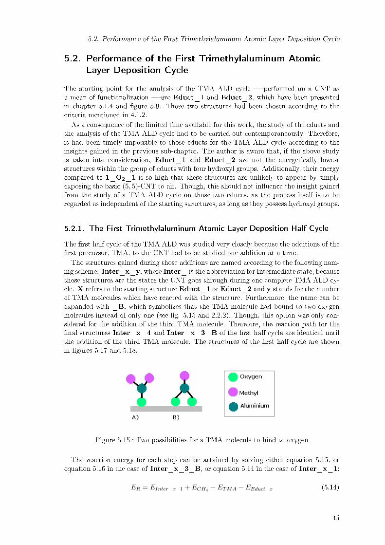
5.2. Performance of the First Trimethylaluminum Atomic Layer Deposition Cycle
5.2. Performance of the First Trimethylaluminum Atomic
Layer Deposition Cycle
The starting point for the analysis of the TMA ALD cycle � performed on a CNT asa mean of functionalization � are Educt_1 and Educt_2, which have been presentedin chapter 5.1.4 and �gure 5.9. Those two structures had been chosen according to thecriteria mentioned in 4.1.2.As a consequence of the limited time available for this work, the study of the educts and
the analysis of the TMA ALD cycle had to be carried out contemporaneously. Therefore,it had been timely impossible to chose educts for the TMA ALD cycle according to theinsights gained in the previous sub-chapter. The author is aware that, if the above studyis taken into consideration, Educt_1 and Educt_2 are not the energetically loweststructures within the group of educts with four hydroxyl groups. Additionally, their energycompared to 1_O2_1 is so high that these structures are unlikely to appear by simplyexposing the basic (5, 5)-CNT to air. Though, this should not in�uence the insight gainedfrom the study of a TMA ALD cycle on those two educts, as the process itself is to beregarded as independent of the starting structures, as long as they possess hydroxyl groups.
5.2.1. The First Trimethylaluminum Atomic Layer Deposition Half Cycle
The �rst half cycle of the TMA ALD was studied very closely because the additions of the�rst precursor, TMA, to the CNT had to be studied one addition at a time.The structures gained during those additions are named according to the following nam-
ing scheme: Inter_x_y, where Inter_ is the abbreviation for Intermediate state, becausethose structures are the states the CNT goes through during one complete TMA ALD cy-cle. X refers to the starting structure Educt_1 or Educt_2 and y stands for the numberof TMA molecules which have reacted with the structure. Furthermore, the name can beexpanded with _B, which symbolizes that the TMA molecule had bound to two oxygenmolecules instead of only one (see �g. 5.15 and 2.2.2). Though, this option was only con-sidered for the addition of the third TMA molecule. Therefore, the reaction path for the�nal structures Inter_x_4 and Inter_x_3_B of the �rst half cycle are identical untilthe addition of the third TMA molecule. The structures of the �rst half cycle are shownin �gures 5.17 and 5.18.
Figure 5.15.: Two possibilities for a TMA molecule to bind to oxygen
The reaction energy for each step can be attained by solving either equation 5.15, orequation 5.16 in the case of Inter_x_3_B, or equation 5.14 in the case of Inter_x_1:
ER = EInter_x_1 + ECH4 − ETMA − EEduct_x (5.14)
45

5. Results and Discussion
ER = EInter_x_y + ECH4 − ETMA − EInter_x_y−1 (5.15)
ER = EInter_x_3_B + 2ECH4 − ETMA − EInter_x_2 (5.16)
where ECH4 stands for the energy of methane,4 and ETMA stands for the energy of a TMAmolecule.5 The resulting reaction energies one obtains from those equations are shown inthe following diagram (�g. 5.16), as well as in �gures 5.17 and 5.18.
Educt_x 1st TMA addition 2nd TMA addition 3rd TMA addition 4th TMA addition-250.00
-200.00
-150.00
-100.00
-50.00
0.00
Overall reaction energy of the first TMA ALD half cycle
Inter_1_3_B Inter_2_3_B Inter_2_4 Inter_1_4
Step in the TMA ALD cycle
Ove
rall
reac
tion
ener
gy
Figure 5.16.: The overall reaction energies for the �rst TMA ALD half cycleThis diagram shows the overall reaction energy during the �rst half of the
TMA ALD cycle. Because the structures Inter_1_3_B and Inter_2_3_B
only react with three TMA molecules, their reaction energy is only shown until
the addition of the third TMA molecule. The reaction energies were gained
according to equations 5.14, 5.15 and 5.16.
As one can see in �gure 5.16, the whole �rst half of the TMA ALD cycle is a highlyexothermic process as it was anticipated, because the TMA ALD itself is a strongly exother-mic process. The energy the system gains through the addition of the �rst and the secondTMA molecule is nearly identical for both studied structures Educt_1 and Educt_2,with reaction energies of 60-70 kcal/mol and 30-35 kcal/mol, respectively. A reason forthis could be that those two TMA molecules are bound to the two outer oxygen molecules,which have about the same distance from each other in both structures.Starting with the addition of the third TMA molecule the reaction energies for a fur-
ther addition of TMA start to di�er greatly. The lowest reaction energy is shown byInter_2_3, with only -27.75 kcal/mol for the bonding of the third Dimethylaluminum to
4ECH4 =-40.466 Ha5ETMA =-361.928 Ha
46

5.2. Performance of the First Trimethylaluminum Atomic Layer Deposition Cycle
First half of the TMA ALD cycle of Educt_1 ending with Inter_1_4
First TMA ALD half cycle
-193,41 kcal/mol
-60.
29 k
cal/m
ol
-35.07 kcal/mol -48.08 kcal/mol
-49.
97 k
cal/m
ol
Educt_1 Inter_1_4
Inter_1_3
Inter_1_2
Inter_1_1
First half of the TMA ALD cycle of Educt_1 ending with Inter_1_3_B
First TMA ALD half cycle
-139,81 kcal/mol
-60.2
9 kca
l/mol
-35.07 kcal/mol
-44.45 kcal/mol
Inter_1_3_BEduct_1
Inter_1_1
Inter_1_2
Figure 5.17.: The �rst half of the TMA ALD cycle of Educt_1 ending with Inter_1_4or Inter_1_3_B
This schema shows fragments of the CNT during the �rst half of the TMA
ALD cycle, where the �rst precursor, TMA, reacts with the hydroxyl groups
present on the CNT under the dissociation of methane. Besides the reaction
energy of each single step of the half cycle, the overall reaction energy is also
included on the lowermost arrow.
For a better comprehensibility the methane and TMA molecules, which were
included in the reaction energy calculations (see eq. 5.14, 5.15 and 5.16) are
not included in this schema.
47

5. Results and Discussion
First half of the TMA ALD cycle of Educt_2 ending with Inter_2_4
First TMA ALD half cycle
-177,42 kcal/mol
-60.
29 k
cal/m
ol
-69.
49 k
cal/m
ol
-30.58 kcal/mol
-49.
60 k
cal/m
ol
-27.75 kcal/mol
Educt_2 Inter_2_4
Inter_2_2
Inter_2_1Inter_2_3
First half of the TMA ALD cycle of Educt_2 ending with Inter_2_3_B
First TMA ALD half cycle
-69.4
9 kca
l/mol
-30.58 kcal/mol
-73.67 kcal/mol
-173.74 kcal/mol
Inter_2_1 Inter_2_2
Educt_2 Inter_2_3_B
Figure 5.18.: The �rst half of the TMA ALD cycle of Educt_2 ending with Inter_2_4or Inter_2_3_B
This schema shows fragments of the CNT during the �rst half of the TMA
ALD cycle, where the �rst precursor, TMA, reacts with the hydroxyl groups
present on the CNT under the dissociation of methane. Besides the reaction
energy of each single step of the half cycle the overall reaction energy is also
included on the lowermost arrow.
For a better comprehensibility the methane and TMA molecules, which were
included in the reaction energy calculations (see eq. 5.14, 5.15 and 5.16) are
not included in this schema.
48

5.2. Performance of the First Trimethylaluminum Atomic Layer Deposition Cycle
the CNT. The reason why the other three structures gain twice or even thrice the amountcould be that in two of those structures a coordinate bond is formed between the newlyadded aluminum atom and one of the oxygen atoms, while in the third structure the SVdefect is opened further. The reason why the coordinate bonds are only formed now isthat during the second addition of TMA the aluminum and oxygen atoms had not beenclose enough to interact with each other.Furthermore, the energy di�erence of about 25 kcal/mol between Inter_2_3_B and
Inter_1_3, even though both possess an aluminum atom which is in a coordinate bondwith one oxygen atom, can be explained by the tetrahedral structure of the aluminumatom formed in Inter_2_3_B additionally to the coordinate bond, which is energeticallyfavorable.This is proved by the �nal reaction energies for the �rst half cycle of the TMA ALD
performed on the CNTs. While the structures Inter_x_4 have not only gained a furtherenergy loss of about 50 kcal/mol through the addition of a fourth TMA molecule, butalso another coordinate bond, Inter_2_4 in the end still has about the same energy asInter_2_3_B. This means that the CNT gains the same energy out of forming a tetrahe-dral structure as if another TMA is added. Though, in the end Inter_1_4 still possessesthe lowest energy because it has two coordinate bonds, instead of one like Inter_2_4and Inter_2_3_B.To sum up the current results, the energy for performing this �rst TMA ALD half cycle
�uctuates between -140 kcal/mol and -193 kcal/mol, depending on the number of aluminumatoms, which have been added to the CNT, and the number of formed coordinate bondsbetween the oxygen and aluminum atoms. According to the study carried out by CharlesB. Musgrave in [18], the energy for the reaction of TMA with a hydroxyl group whereone methane molecule desorbs is about -39 kcal/mol. Since during this half cycle for all�nal products, methane was desorbed four times, the minimal reaction energy should beabout -116 kcal/mol. This is only 24 kcal/mol higher than for Inter_1_3_B, where nocoordinate bonds are formed and so only the SV defect and the CNT itself in�uenced thereaction energy.The CNT and SV defect only seem to in�uence the energy during the addition of the
�rst aluminum atom by 20-30 kcal/mol, if the energy for this reaction is based on thevalue of -39 kcal/mol mentioned previously. Since the energies for the addition of TMAwhile only a coordinate bond was formed is a constant 48-50 kcal/mol, the energy of thecoordinate bond can be determined by a value of about 10 kcal/mol. This is about thevalue of 9.5 kcal/mol given for an aluminum coordinate bond in [26].
5.2.2. The Second Trimethylaluminum Atomic Layer Deposition Half Cycle
The second half of the TMA ALD cycle is not studied as closely as the �rst half in thesense that instead of calculating the reaction energy for each substitution of a methyl groupby a hydroxyl group, only the reaction energy for substituting all of the methyl groups onthe CNT with hydroxyl groups are calculated. This di�erent approach was taken becausehere, it had not been necessary to study one substitution at a time and also because thetime available only allowed for an analysis of the �nal product of the second TMA ALDhalf cycle.To show that these structures are the product of the second TMA ALD half cycle, and are
the �nal product of one TMA ALD cycle, their names where changed from Inter_x_yto Product_x_y. Consequently, the �nal functionalized CNTs are Product_1_4,Product_1_3_B, Product_2_4 and Product_2_3_B and are shown in �gure5.20.
49

5. Results and Discussion
The reaction energy for the second half cycle can be attained by solving either equation5.17 or equation 5.18:
ER = EProduct_x_4 + 8ECH4 − EInter_x_4 − 8EH2O (5.17)
ER = EProduct_x_3_B + 5ECH4 − EInter_x_3_B − 5EH2O (5.18)
where EH2O is the energy of water6. The resulting reaction energies obtained from thoseequations are shown in the following �gure 5.20, which is a summary of the whole TMAALD cycle performed on the chosen CNTs. Additionally the reaction energies were addedto the previous diagram in �gure 5.16, so that the new diagram in �gure 5.19 now showsthe overall reaction energies for one complete TMA ALD cycle.
Figure 5.19.: Overall reaction energies for the whole TMA ALD cycleThis diagram shows the overall reaction energy during the TMA ALD cycle.
Because the structures Inter_1_3_B and Inter_2_3_B only react with three
TMA molecules, their reaction energy stays unchanged between the addition
of the third and fourth TMA molecule. Therefore there line is dashed between
those two steps. The reaction energies were gained according to equations 5.14,
5.15 and 5.16, as well as equations 5.17 and 5.18.
As one can see in �gure 5.20, both CNTs who possess four aluminum atoms have areaction energy which is about 100 kcal/mol lower than the one for the CNTs with onlythree aluminum atoms for the exchange of the methyl groups with hydroxyl groups. This isnot surprising since the possession of four aluminum atoms entails that eight methyl groups
6EH2O=-76.383 Ha
50

5.2. Performance of the First Trimethylaluminum Atomic Layer Deposition Cycle
The TMA ALD cycle performed on Educt_1 and Educt_2
First TMA ALD half cycle
Second TMA ALD half cycle
Inter_1_4
Inter_1_3_B
Inter_2_3_B
Inter_2_4
Product_1_4
Product_1_3_BProduct_2_4
Product_2_3_B
ETMA
= -482.50 kcal/mol
ETMA
= -341.61 kcal/mol
ETMA
= -472.67 kcal/mol
ETMA
= -332.13 kcal/mol
-289.09 kcal/mol
-201.79 kcal/mol
-295.25 kcal/mol
-158.39 kcal/mol
Educt_1 Educt_2
-193.41 kcal/mol
-139.81 kcal/mol
-173.74 kcal/mol
-177.42 kcal/mol
Figure 5.20.: Schema of the TMA ALD performed on Educt_1 and Educt_2This schema summarizes the studied TMA ALD performed on Educt_1 and
Educt_2 in the form of chosen excerpts of the CNT during the functionalization
process. Besides the overall energy for each half cycle, it also gives the overall
energy for the whole TMA ALD at the bottom of the schema.
For clarity the methane, water and TMA molecules, which were included in
the reaction energy calculations (see eq. 5.14, 5.15, 5.16, 5.17 and 5.18), are
not shown in this schema.51

5. Results and Discussion
are replaced by hydroxyl groups during the second TMA ALD half cycle. The other twostructures on the other hand only exhibit �ve methyl groups, which can be exchangedduring the reaction with the second precursor. The resulting energy di�erence is aboutthe value of the energy caused by the di�erent numbers of hydroxyl groups, according to[18]. There, the overall energy for the exchange of one methyl group with one hydroxylgroup through the reaction with water, the second precursor, is about -34 kcal/mol. Ifthis amount is taken three times it accords to -102 kcal/mol, which explains the energydi�erence of about 100 kcal/mol.Also, the reaction energy for this half cycle is in good agreement with the expected
energy one gains from the value above. In the case of exchanging �ve methyl groups thereaction energy should be about 170 kcal/mol and about 272 kcal/mol for eight methylgroups. This means that opposed to the previous half cycle the CNT and the SV defectmost likely do not a�ect the reaction energies any longer.However, it is surprising that the structure Inter_2_3_B in comparison to
Inter_1_3_B has a reaction energy for the hydroxylation which is about 40 kcal/mollower, though, both of the structures possess the same amount of methyl groups. A reasonfor this energy di�erence could be that in Product_1_3_B the SV defect is expandedfurther. Additionally, in Product_1_3_B the aluminum atom, bound to the oxygenatoms of the carbon atoms 2 and 3, has moved closer to the aluminum atom connected tocarbon atom 4. Because of the reduced distance of the three aluminum atoms, hydrogenbonds can be formed between the hydroxyl groups.Therefore, the hydrogen bonds and theexpansion of the SV defect lead to an additional energy loss.For the TMA ALD performed on CNTs as a whole one can say that even though the reac-
tion energy for each step depends on the initial structures, after one TMA ALD cycle onlythe number of TMA molecules which have reacted with the CNT determine the reactionenergy. In the case of the �nal structures, this means that Product_x_4 and Prod-uct_x_3_B have, independently of x, an overall reaction energy of about -475 kcal/moland -335 kcal/mol, respectively. The energy one expects to gain, according to the valuesgiven in [18] for a TMA ALD carried out on an aluminum oxide surface, are 428 kcal/moland 326 kcal/mol respectively. Taking into account the formed coordinate bonds, the ener-gies are in good agreement, considering that di�erent surfaces were coated with the TMAALD process.However, the dependence of the reaction energy on the number of TMA molecules may
be a result of the two similar starting structures, who both possess a band of hydroxylgroups. To verify this, further investigations are necessary. For example 1_O2_1_Aor 1_H2O_2_B from 5.1.4 would be suitable for this study as 1_O2_1_A does notpossess such a hydroxyl group band and 1_H2O_2_B's band only consists of threehydroxyl groups and both of their energies are about 40 kcal/mol lower than Educt_x.
52

6. Summary and Outlook
In the present work, basic surface reaction steps of the TMA ALD process have beenanalyzed by quantum chemical methods. Reaction energies for the two main aspects ofthis thesis � the formation of possible educts and the performance of one TMA ALD cycle� have been calculated using density functional theory.The �rst major part of the study is the investigation of the di�erent educts based on the
(5, 5)-CNT and its reactions with air (containing water and oxygen). It was shown thatthe CNTs primarily react with the present oxygen to 1_O2_1 (see �g. 6.1, left). Withan energy di�erence of at least 40 kcal/mol this structure is the dominant species out of allthe studied educts which have reacted with an oxygen molecule. As the TMA ALD processrequires hydroxyl groups, the search for energetically lower structures containing hydroxylgroups has started. The energetically most favorable educt found is 1_H2O_1 (shownin �gure 6.1, right). Its reaction energy is 21 kcal/mol higher than the energy gained byforming 1_O2_1.
Figure 6.1.: The educts 1_O2_1(l.) and 1_H2O_1 (r.)
Consequently, all the studied educts which contain the necessary hydroxyl groups for theTMA ALD process are energetically far higher than 1_O2_1. Additionally, a possiblewater addition reaction on 1_O2_1 which could lead to the formation of hydroxyl groups(see �g. 5.14) has not yet been con�rmed. Because of those current �ndings it is suggestto avoid any exposure of the CNTs to oxygen if a TMA ALD is to be carried out. Insteadthey should be placed in an environment which contains water vapor, so that at least two ofthe necessary hydroxyl groups can bind to the CNT (see 5.1.3). This is necessary becausethe educts of this group are energetically at least 110 kcal/mol higher than 1_O2_1 andwould not be formed if oxygen existed in their environment.As the position of the functional groups has as much in�uence on the energy of the
functionalized CNT as the functional groups themselves, it is possible that other structureswith hydroxyl groups exist, which are energetically more favorable than 1_O2_1. If thisis the case, then it would not be necessary to ensure that the CNTs do not come intocontact with oxygen.There are also other types of ALD which require initially oxygen groups instead of
hydroxyl groups on the surface. One example for this is the copper ALD which wasalready carried out by my colleague Marcel Melzer at the Fraunhofer ENAS [23]. This
53

6. Summary and Outlook
ALD process works with both � oxygen atoms and hydroxyl groups. Therefore, this typeof reactions would work with any of the educts.The second major part of the investigation is the analysis of one TMA ALD cycle, which
is performed exemplary on two chosen CNTs with four hydroxyl groups. The study hasshown, that, as long as there are hydroxyl groups, it is possible to perform a TMA ALDon CNTs, or more precisely: on the SV defects of the CNTs. Furthermore, the CNT andits SV defect only in�uence the reaction energy during the �rst half of the �rst TMA ALDcycle. Thus, it can be assumed that during a second cycle the CNT does not in�uence thereaction energy any longer. Additionally, the CNT increases the formation of coordinatebonds between the aluminum and oxygen atoms (see �g. 6.2).
Figure 6.2.: Product_1_4, which possesses �ve coordinate bonds
Based on the current results one can conclude that the overall reaction energy for oneALD cycle is only dependent on the number of TMA molecules which have reacted withthe CNT and is independent of where the hydroxyl groups are located at the beginning.Though, since only four �nal structures were gained, this conclusion needs further veri�-cation, especially since the two used educts in this work have similar structures.To conclude the �ndings of this thesis one can say that a �rst step to the understanding
of performing di�erent kind of ALDs has been done. Especially the analysis of the di�erentpossible educts is an important step, because most ALD processes require hydroxyl groupsand/or oxygen atoms as their starting point. Furthermore, the study of one TMA ALDcycle has shown that the CNTs do positively in�uence the reaction energy of the TMAALD, making the process even more exothermic. It is likely that this in�uence of the CNTduring the �rst half cycle will be found by other kinds of ALDs as well. Nevertheless,the potential of functionalizing CNTs with ALD methods is not exhausted yet. Therefore,other interesting aspects could be studied in future works.One of those works could be the performance of a second TMA ALD cycle to see if
the assumption of the CNT only in�uencing the �rst cycle is correct. Also, it would beadvisable to study other CNTs, namely semimetallic/semiconducting CNTs. Additionally,metallic CNTs which possess a lower number of hydroxyl groups or where the four hydroxylgroups are positioned elsewhere, like in 1_O2_1_A or 1_H2O_2_B from 5.1.4, areof interest.A very important study would be the search of transition states for the already presented
�rst TMA ALD cycle. This is necessary to gain the barriers for the di�erent studied
54

reactions. They in turn are needed to determine the reaction rates, and thus, which of thefour possible reaction pathways is the dominant one, or if all four have about the sameprobabilities.In addition, it would be important to determine if it is possible to perform an experi-
mental TMA ALD on CNTs, to verify if hydroxyl groups can be bound to CNTs underthe presence of oxygen and thus, if an aluminum oxide layer can be formed on them. Thiscould also be achieved by expanding the study of the educts to include a variety of newpositions for the functional groups, but this approach is very time consuming and it is notsure, whether this e�ort will lead to energetically more favorable structures.Therefore, it would be advisable to expand the study of the educts into another direction,
namely the search for the transition states of the already studied structures to be able tocalculate the reaction rates and the accompanying barriers. This would be an importantinvestigation, because it is possible that even if currently 1_O2_1 is the energeticallyfavored structure, the barrier to form this structure may be too high to be formed freelyand therefore, more favorable structures for the TMA ALD might be found instead.
55


A. Appendix
A.1. Note on the Multiplicity
For reliable energy calculations the multiplicity of the educts and the products must beidentical. In the case of the basic (5, 5)-CNT, the SV defect with its four free electronsis the reason why it is a open-shell system with an unknown multiplicity. Both � thesinglet state, as well as the triplet state � would be possible for this structure. Theaim of a previous study was to determine the multiplicity of this structure. In this studythe energy for the basic (5, 5)-CNT, as well as nine di�erent with hydroxyl and hydrogenfunctionalized structures, was calculated twice � once for the singlet state and once fortriplet state � with an enforced multiplicity for all studied structures. This is necessary asboth educt and product must have an identical multiplicity. The resulting reaction energyof both states are shown in �gure A.1.
Structure_1Structure_2
Structure_3Structure_4
Structure_5Structure_6
Structure_7Structure_8
Structure_9
-60.0
-50.0
-40.0
-30.0
-20.0
-10.0
0.0
10.0
20.0
30.0
Comparison of reaction energies~ for Singlet and Triplet state ~
Reaction energy for the singlet state
Reaction energy for the triplet state
Structure
Rea
ctio
n en
ergy
in k
cal/m
ol
Figure A.1.: Reaction energies for the singlet and triplet state
As one can see the triplet state is only favorable for two thirds of the analyzed structures.Therefore, it is not possible to determine the correct multiplicity of the basic (5, 5)-CNT.Consequently, the reaction energies have to be based on a closed-shell-system instead. Inthe present work this is achieved by using one of the pre-functionalized CNTs, where allfour free electrons of the defect are saturated.
57

A. Appendix
A.2. Note on the Computation Time
Here, some information regarding the computational costs of the di�erent calculations willbe given.The reason why only the TMA ALD cycle had been studied with Materials Studio is that
only three computations can be carried out simultaneously with the available licenses atthe Fraunhofer ENAS. The time needed for one geometry optimization lies between one to�ve days. The following frequency analysis takes about seven to fourteen days. Therefore,theoretically about three to six structures can be studied with Materials Studio per month.Taking into account that sometimes the number of optimization cycles had been too lowfor the energy to reach the convergence value, or that the geometry optimizations yieldedtransition states, further computations had to be performed. This reduced the amount ofmonthly studied structures to about four.The number of available licenses is also an additional reason why a cluster molecule was
chosen instead of a periodic system. The use of a periodic system would have limited thenumber of simultaneous computations to two due to the license model of Materials Studio.For Turbomole on the other hand the number of parallel computations is not limited by
the amount of available licenses, but by the number of free nodes available on the CHIC,where the computations were carried out. Because of the almost unlimited amount ofparallel computations, it was used for the extensive study of the educts. The drawbackof Turbomole is that the computation time is much larger. For example the geometryoptimization takes about one to three weeks, while the frequency analysis can take up toa month.
58

A.3. Comparison between Dmol³ and Turbomole
A.3. Comparison between Dmol³ and Turbomole
In a previous study a comparison between Turbomole and Materials Studio's Dmol³ hasbeen carried out. The same settings as for the calculations in chapter �ve were used, namelyDMol³ with PBE/DNP and Turbomole with BP86/def2-TZVP. The studied structures inthis case were (5, 5)-CNTs with a SV defect, which were functionalized with one hydroxylgroup and one hydrogen atom. The resulting reaction energies shown in �gure A.2 are theenergies for the functionalization.
Structure_1Structure_2
Structure_3Structure_4
Structure_5Structure_6
Structure_7Structure_8
Structure_9-60.0
-50.0
-40.0
-30.0
-20.0
-10.0
0.0
10.0
20.0
30.0
Comparison between Turbomole and Dmol³~ Reaction energy for different functionalized CNTs ~
Dmol³ - DNP/PBE Turbomole – def2-TZVP/BP
Structure
Rea
ctio
n en
ergy
in k
cal/m
ol
Figure A.2.: Comparison of the reaction energies of Turbomole and Dmol³
As one can see the reaction energies of both programs are in good agreement, withTurbomole constantly having a slightly higher energy of about 2 kcal/mol. A comparisonof those results with other methods like MP2 or the Coupled Cluster method had not beenpossible, because of the structures' size.
59

A. Appendix
A.4. Tables of Energies for the Studied Educts in 5.1
A.4.1. Educts with Two Oxygen Atoms
Educt Energy in Ha Reaction energy based on 1_O2_1
1_O2_1 -3936.71 0.001_O2_2 -3936.56 90.871_O2_3 -3936.56 88.611_O2_4 -3936.56 91.261_O2_5 -3936.62 54.421_O2_6 -3936.64 39.461_O2_7 -3936.61 59.501_O2_8 -3936.64 42.001_O2_9 -3936.63 48.28
Table A.1.: Overview of the reaction energies of the educts with two oxygen atoms(1_O2_x)
A.4.2. Educts with Two Hydroxyl Groups and One Oxygen Atom
Name Energy in Ha Reaction energy based on 1_O2_1
1_H2O_1 -4013.14 21.101_H2O_2 -4013.05 78.191_H2O_3 -4013.06 73.331_H2O_4 -4013.03 86.881_H2O_5 -4013.09 50.641_H2O_6 -4013.10 42.851_H2O_7 -4013.09 50.721_H2O_8 -4013.12 32.041_H2O_9 -4013.04 84.56
Table A.2.: Overview of the reaction energies of the educts with two hydroxyl groups andone oxygen atom (1_H2O_x)
60

A.4. Tables of Energies for the Studied Educts in 5.1
A.4.3. Educts with Two Hydroxyl Groups and Two Hydrogen Atoms
Name Energy in Ha Reaction energy based on 1_O2_1
2_H2O_1 -3939.05 111.622_H2O_2 -3938.97 161.802_H2O_3 -3938.99 151.592_H2O_4 -3939.04 118.652_H2O_5 -3939.02 130.012_H2O_6 -3939.04 117.182_H2O_7 -3939.04 121.222_H2O_8 -3939.06 110.092_H2O_9 -3938.97 165.69
Table A.3.: Overview of the reaction energies of the educts with two hydroxyl groups andtwo hydrogen atoms (2_H2O_x)
A.4.4. Educts with Four Hydroxyl Groups
Name Energy in Ha Reaction energy based on 1_O2_1
1_H2O_2_B -4089.57 45.641_H2O_4_B -4089.53 66.32Educt_1 -4089.51 80.42Educt_2 -4089.50 90.691_O2_1_A -4089.55 54.491_O2_1_B -4089.55 55.501_O2_1_C -4089.39 159.94
Table A.4.: Overview of the reaction energies of the educts with four hydroxyl groups
A.4.5. Educts with Peroxy Groups
Name Energy in Ha Reaction energy based on 1_O2_1
2_O2_1 -4086.94 112.322_O2_2 -4012.93 154.802_O2_3 -4013.04 84.66
Table A.5.: Overview of the reaction energies of the educts with at least one peroxy group
61
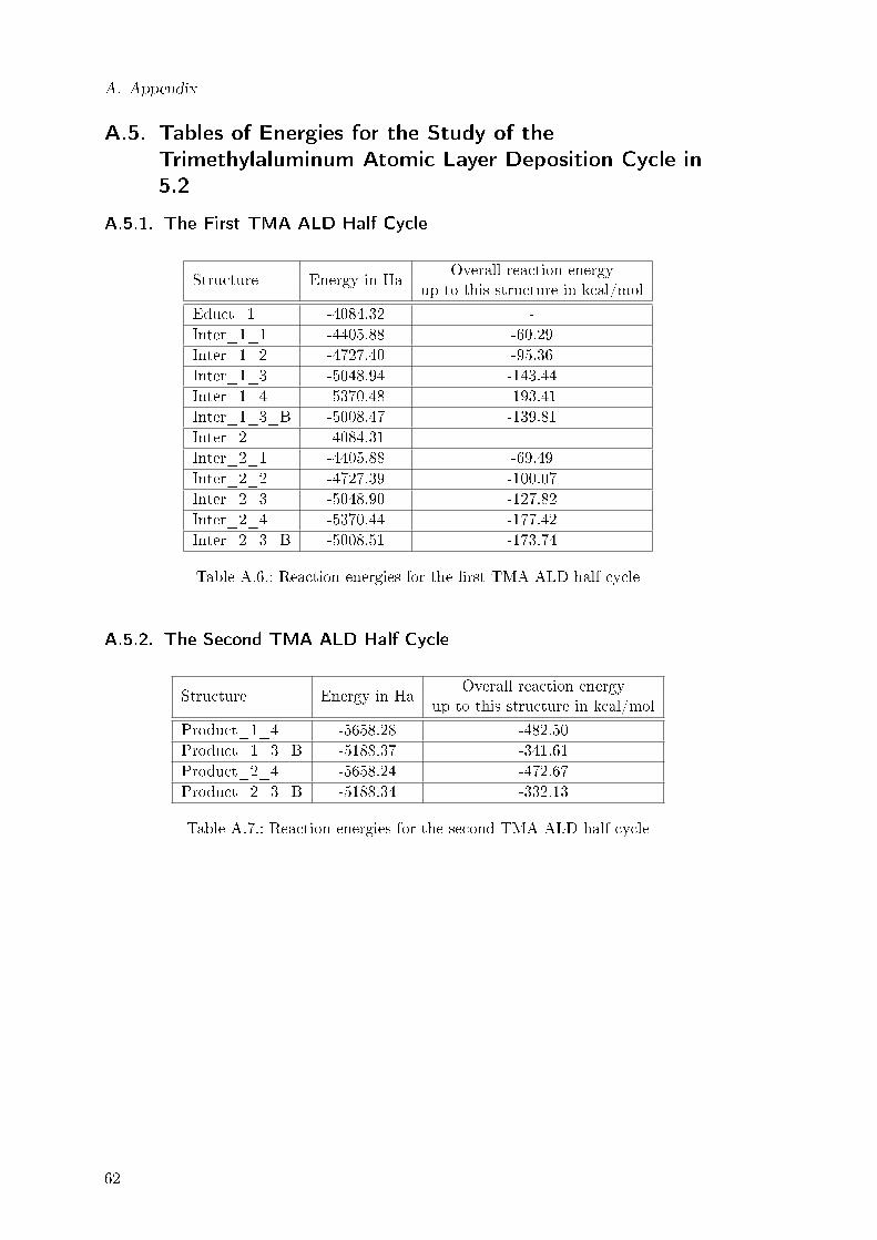
A. Appendix
A.5. Tables of Energies for the Study of the
Trimethylaluminum Atomic Layer Deposition Cycle in
5.2
A.5.1. The First TMA ALD Half Cycle
Structure Energy in HaOverall reaction energy
up to this structure in kcal/mol
Educt_1 -4084.32 -Inter_1_1 -4405.88 -60.29Inter_1_2 -4727.40 -95.36Inter_1_3 -5048.94 -143.44Inter_1_4 -5370.48 -193.41Inter_1_3_B -5008.47 -139.81Inter_2 -4084.31 -Inter_2_1 -4405.88 -69.49Inter_2_2 -4727.39 -100.07Inter_2_3 -5048.90 -127.82Inter_2_4 -5370.44 -177.42Inter_2_3_B -5008.51 -173.74
Table A.6.: Reaction energies for the �rst TMA ALD half cycle
A.5.2. The Second TMA ALD Half Cycle
Structure Energy in HaOverall reaction energy
up to this structure in kcal/mol
Product_1_4 -5658.28 -482.50Product_1_3_B -5188.37 -341.61Product_2_4 -5658.24 -472.67Product_2_3_B -5188.34 -332.13
Table A.7.: Reaction energies for the second TMA ALD half cycle
62

Bibliography
[1] `Accelrys Software Inc., Materials Studio Release Notes, Release 6.0, San Diego: Ac-celrys Software Inc., 2011'.
[2] `TURBOMOLE V6.3 2011, a development of University of Karlsruhe andForschungszentrum Karlsruhe GmbH, 1989-2007, TURBOMOLE GmbH, since 2007;available from http://www.turbomole.com.'.
[3] Becke, A. D.: 1988, `Density-functional exchange-energy approximation with correctasymptotic behavior'. Physical Review A 38(6), 3098�3100.
[4] Burg, B. R., T. Helbling, C. Hierold, and D. Poulikakos: 2011, `Piezoresistive pres-sure sensors with parallel integration of individual single-walled carbon nanotubes '.Journal of Applied Physics 109(6), 064310�064315.
[5] Capelle, K.: 2006, `A Bird's-Eye View of Density-Fuctional Theory'. Brazilian Journal
of Physics 36(4A), 1318�1343.
[6] Cleveland, E. D. R.: 2010, `Atomic layer deposition conformality and process opti-mization: Transitioning from 2-dimensional planar systems to 3-dimensional nanos-tructures'. Bachelor thesis, The University of Maryland.
[7] Daenen, M., R. de Fouw, B. Hamers, P. Janssen, K. Schouteden, and M. Veld:2003, `The Wondrous World of Carbon Nanotubes: a review of current carbonnanotube technologies'. http://students.chem.tue.nl/ifp03/Wondrous%20World%20of%20Carbon%20Nanotubes_Final.pdf [Online; accessed 24 August 2012].
[8] Delly, B.: 1990, `An all-elctron numerical methode for solving the local density func-tional for polyatomic molecules'. The Journal of Chemical Physics 92(1), 508�517.
[9] Delly, B.: 2000, `From molecules to solids with the DMol3 approach'. The Journal ofChemical Physics 113(18), 7756�7764.
[10] Delly, B.: 2006, `Ground-state enthalpies: evaluation of electronic structure ap-proaches with emphasis on the density functional method'. The Journal of Physical
Chemistry A 110(50), 13632�13639.
[11] Dirac, P. A. M.: 1929, `Quantum Mechanics of Many-Electron Systems'. Proceedingsof the Royal Society of London. Series A 123(792), 714�733.
[12] Förster, A.: 2012, `Praktikumsbericht'.
[13] George, S. M.: 2010, `Atomic Layer Deposition: An Overview'. Chemical Reviews
110(1), 111�131.
[14] Hohenberg, P. and W. Kohn: 1964, `Inhomogeneous Electron Gas'. Physical Review136(3B), B864�B871.
[15] Iijima, S.: 1991, `Helical microtubules of graphitic carbon'. Nature 354(6348), 56�58.
63

Bibliography
[16] Irvine, G.: 2011, `High-k semiconductor materials from a chem-ical manufacturer's perspective'. http://citrix.cleanrooms.
com/index/display/article-display/1015272792/articles/
solid-state-technology/semiconductors/materials/2011/2/
high-k-semiconductor-materials-from-a-chemical-manufacturer-pers.html
[Online; accessed 13 August 2012].
[17] Kebes: 2005, `CNTnames.png'. http://en.wikipedia.org/wiki/File:CNTnames.
png [Online; accessed on 11 August 2012 ].
[18] Knez, M. and N. Pinna (eds.): 2011, Atomic Layer Deposition of Nanostructured
Materials. Weinheim: WILEY-VCH Verlag, �rst edition.
[19] Koch, W. and M. C. Holthausen: 2001, A Chemist's Guide to Density Functional
Theory. Weinheim: WILEY-VCH Verlag, second edition.
[20] Kodas, T. and M. Hampden-Smith: 1994, The chemistry of metal CVD. Weinheim:VCH Verlagsgesellschaft mbH.
[21] Kohn, W. and L. J. Sham: 1965, `Self-Consistent Equations Including Exchange andCorrelation E�ects'. Physical Review 140(4A), A1133�A1138.
[22] Lee, Y.-S. and N. Marzari: 2006, `Cycloaddition Functionalizations to Preserve orControl the Conductance of Carbon Nanotubes'. Physical Review Letters 97(11),116801�116804.
[23] Melzer, M.: 2011, `Atomic Layer Deposition and Microanalysis of Ultrathin Layers'.Bachelor thesis, University of Technology Chemnitz.
[24] Nobelprize.org: 2012, `Nobel Prizes 1998'. http://www.nobelprize.org/nobel_
prizes/lists/year/?year=1998 [Online; accessed 11 August 2012 ].
[25] Novoselov, K. S., A. K. Geim, S. V. Morozov, D. Jiang, Y. Zhang, S. V. Dubonos,I. V. Grigorieva, and A. A. Firsov: 2004, `Electric Field E�ect in Atomically ThinCarbon Films'. Science 306(5696), 666�669.
[26] Olah, G. A., G. K. S. Prakash, R. E. Williams, K. Wade, and A. Molnar: 2011,Hypercarbon Chemistry. Hoboken, New Jersey: WILEY-VCH Verlag, second edition.
[27] Perdew, J. P.: 1986, `Density-functional approximation for the correlation energy ofthe inhomogeneous electron gas'. Physical Review B 33(12), 8822�8824.
[28] Perdew, J. P., K. Burke, and M. Ernzerhof: 1996, `Generalized Gradient Approxima-tion Made Simple'. Physical Review Letters 77(18), 3865�3868.
[29] Pourfath, M.: 2007, `Numerical Study of Quantum Transport in Carbon NanotubeBased Transistors'. Ph.D. thesis, University of Technology Wien. http://www.iue.
tuwien.ac.at/phd/pourfath/node13.html [Online; accessed on 11 August 2012].
[30] QuantumWise A/S: 2010, `Periodic Table of Carbon Nanotubes'. http://www.
quantumwise.com/documents/CNT_PeriodicTable.pdf [Online; accessed 12 August2012].
[31] Radushkevich, L. and V. Lukyanovich: 1952, `O strukture ugleroda, obrazujucegosjapri termiceskom razlozenii okisi ugleroda na zeleznom kontakte'. Zurn Fisic Chim 26,88�95.
64

Bibliography
[32] Shukla, P. and P. Mishra: 2010, `E�ects of diameter, length, chirality and defects onthe scavenging action of single-walled carbon nanotubes for OH radicals: A quantumcomputational study'. Chemical Physicy 369(2-3), 101�107.
[33] Slater, J. C.: 1951, `A Simpli�cation of the Hartree-Fock Method'. Physical Review
81(3), 385�390.
[34] Thomson Reuters: 2012, `Results for Topic=(CNT); Timespan=2002-2012; Searchlanguage=English; Lemmatization=On'. www.webofknowledge.com [Online; accessed11 August 2012].
[35] TURBOMOLE GmbH, `TURBOMOLE - Program Package for ab initio ElectronicStructure Calculations'. http://www.turbomole-gmbh.com/ [Online; accessed 12 Au-gust 2012 ].
[36] TURBOMOLE GmbH: 2011, `Turbomole Version 6.3 User's Manual'. page 57 http://www.turbomole-gmbh.com/manuals/version_6_3/DOC.pdf [Online; accessed 25 Au-gust 2012 ].
[37] Vosko, S. H., L. Wilk, and M. Nusair: 1980, `Accurate spin-dependent electron liquidcorrelation energies for local spin density calculations: a critical analysis'. CanadianJournal of Physics 58(8), 1200�1211.
[38] Weigend, F.: 2006, `Accurate Coulomb-�tting basis sets for H to Rn'. Physical Chem-
istry Chemical Physics 8(9), 1057�1065.
[39] Weigend, F., M. Häser, H. Patzelt, and R. Ahlrichs: 1998, `RI-MP2: Optimized Aux-iliary Basis Sets and Demonstration of E�ciency'. Chemical Physics Letters 294(1-3),143�152.
[40] Wikipedia: 2012a, `Carbon nanotube � Wikipedia, The Free Encyclopedia'. http://en.wikipedia.org/w/index.php?title=Carbon_nanotube&oldid=506108303 [On-line; accessed 11 August 2012].
[41] Wikipedia: 2012b, `Graphene � Wikipedia, The Free Encyclopedia'. http://en.
wikipedia.org/w/index.php?title=Graphene&oldid=506617037 [Online; accessed11 August 2012].
[42] Yan, F., C. Zhang, D. Cott, G. Zhong, and J. Robertson: 2010, `High-density growthof horizontally aligned carbon nanotubes for interconnects'. Physical Status Solidi B247(11-12), 2669�272.
65


Acknowledgment
I would like to thank Dr. Joachim Friedrich, who not only generously accepted to positionof the �rst examiner, but also was a great help during the creation of this work by o�eringcomputational advises as well as the feedback regarding the writing.
Secondly, I would like to thank Prof. Dr. Stefan E. Schulz for accepting the positionof second examiner.
I would also like to thank the whole group of the Back-end of Line department in theFraunhofer ENAS for their support. Especially Dr. Jörg Schuster for his feedback andhelpful advice to improve this work and Christian Wagner for having spent many hoursreading the di�erent versions of the current chapters and always giving helpful feedbackfor improvement. I also thank Dr. Thomas Wächtler and Marcel Melzer for answering allmy questions concerning the atomic layer deposition.
67