back-flushing valves · back-flushing valves updated 02/2012 introduction 5 hydraulic back-flushing...
TRANSCRIPT

Back-F
lushin
g V
alv
es
Cata
logue
Back-Flushing Valves
Pro
du
ct
Ca
talo
gu
e
Back-F
lush
ing
Valv
es

updated 02/2012
Back-Flushing Valves Dorot’s Areas of Activity
WATERWORKSDorot’s valves are specially designed to comply with all the demands of waterworks systems such as: pressure management, low flow regulation, leakage prevention, pump control, level control, surge prevention, sewage and water treatment.
IRRIGATIONDorot is a leader in Automatic Control valves for irrigation applications: drip irrigation, greenhouses, turf and landscaping. The innovative state of the art products are made of a variety of materials such as: cast Iron, ductile iron, steel, stainless steel, bronze, polyamide and uPVC.
CONSTRUCTION AND INDUSTRYDorot offers control applications for high rise buildings such as: flow and pressure regulation, water hammer prevention and reservoir level control.
FIRE PROTECTIONDorot offers a variety of valves for fire protection applications with UL Approvals.
FILTRATION AND WATER TREATMENTDorot offers a variety of Back Flushing valves for filtration systems. These valves are made of high durability materials for water treatment of aggressive waters.

updated 02/2012
Back-Flushing ValvesTable of Contents
Back-Flushing Valves
Introduction 4
Model 58P (“Plaslite”) 6
Models 57 / 58 (“FlushGAL”) 10
Double Chamber Valve Model 51 / 52 14
Double Chamber Valve Model 62 / 63 18
Control Valves
Double Chamber Valve Model 09 (“Galil”) 22
Normally Closed Valve Model 60 26
Models S-300, S-500, S-100 28
Special Applications For Filtration Systems 30

Back-Flushing Valves
updated 02/2012
Introduction
4
Dorot Control Valves have been delivering successful control valve solutions for back-flush systems for the last 35 years. Due to its strong relationship with leading filter manufacturers around the world, Dorot has succeeded developing the highest-end solutions available in the marketplace with an understanding of filtration system’s needs. The valves are designed and manufactured in-house to offer the highest performance and reliability.
This catalogue will provide designers, dealers and end users with essential, up-to-date data as for the operation principles, technical specifications, hydraulic performance and ordering guides for the whole range of Dorot back-flush valves, including special solutions and control applications.
Filtration is an essential part of every modern water system. Whether the system supplies water for residential, irrigation or industrial use, removing impurities efficiently and ensuring water quality is always a main concern of the system designer.Every filtration method chosen by the designer -screen filters, disc filters, media filters, sand separators or others- require a thorough cleaning procedure to remove the accumulated dirt particles from the filtration element.Cleaning the filtration element can be performed in several ways: manual rinsing, mechanical brushing/scraping, suction by scanner or back-flushing.
In this catalogue we will focus on Dorot products and solutions for automatic back-flush systems for filtration devices.
Back-flushing - The principle of back-flushing consist in applying relatively clean, reverse-flow through the filter element and discharging the water flow that is carrying dirt and particles out of the system through a drain line.
Example: single media filter back- flush principle (without back-flushing valves):
The back-flushing procedure requires numerous valves (at least 4 per filter) operated in a synchronized manner, making it complex to operate manually and costly to automate.Using hydraulic back-flushing valves simplifies the synchronization of the control system, minimizes the number of valves required, and allows valve operation with minimal or no electric power consumption.
Filtration mode Back-flushing mode
OPEN CLOSED
OPEN
CLOSEDOPEN
CLOSED
OPENCLOSED
Drain
Outlet
Inlet
Drain
Outlet
Inlet

Back-Flushing Valves
updated 02/2012
Introduction
5
Hydraulic Back-flushing valve - operation principle:Back-flushing control valves are 3/2, semi-automatic control valves actuated by a pressure command.The valve has 3 ports:• Inlet port connected to the water source• Outlet / Common port connected to the filter• Drain port connected to the drain collector
The valve is controlled manually, electrically or by remote pressure command to change position and connect the outlet and drain ports during the back-flushing cycle.As flushing cycle ends, the valve returns to its normal position- connecting the inlet and outlet ports.
Operating principle of a straight-flow, back-flush control valve:
Media filter back-flush system using back-flush control valves:
Benefits of hydraulic back-flushing valves:
Low-power automation (actuation by the line pressure or by compressed air). Electric actuation is possible using •low-power solenoid valves that can be either fed by continuous power or by battery powered controller.Minimal number of valves required per filter.•No need to synchronize the operation of two valves- one port closes while the other simultaneously opens - the entire •operation is integrated in the back-flush control valve.Simple maintenance, no motor gear or other electro-mechanical elements. •
Flushing modeFiltration mode
Inlet To filters
To Drain
Inlet
ToD
rain
From filters
NC
NO
NC
NO
Outlet
Inlet Drain
Outlet
Inlet Drain
Filtration mode Back-flushing mode

Back-Flushing Valves
updated 02/2012
Model 58P (“Plaslite”)
6
Dorot Model 58P “Plaslite” ® Back-Flushing Control Valve
Reinforced-Polyamide body, Direct Diaphragm-Sealing valve, designed for automatic back-flush of filtration batteries
Features: Corrosion-proof materials (additional versions for sea-water and •aggressive media available)
Sturdy body, made of Glass-Reinforced Polyamide (GRP)•
Light weight •
Valve changes position in a frictionless manner•
Simple and easy maintenance•
Easy installation, no special tools or expertise required.•
Special design models for disc and media filtration systems•

Back-Flushing Valves
updated 02/2012
Model 58P (“Plaslite”)
7
Operating principle:
Dimensions:
Inlet / Outlet Drain Dimensions mm / inch WeightKg / Lbsmm inch mm inch A B C
100 4 100 4 316 / 127/16 170 / 611/16 187 / 73/4 5.5 / 12.2100 4 80 3 316 / 127/16 170 / 611/16 187 / 73/4 5.5 / 12.280 3 80 3 286 / 111/4 164 / 67/16 174 / 6 7/8 4.2 / 9.280 3 50 2 286 / 111/4 164 / 67/16 174 / 6 7/8 4.2 / 9.2
End connections: Inlet / Outlet ports GroovedDrain ports Grooved / Female-threaded
Male-threaded is optional in the 3x2 model (thread standards: NPT / BSP)
Materials:
Part Standard Drinking water Sea water Mines1. Body & Cover PA PA PA PA2. Shaft SST 302 SST 302 SST 316 SST 3163. Spring SST 302 SST 302 SST 316 SST 3164. Screws SST 302 SST 302 SST 316 SST 3165. Seals NR EPDM NR ALD6. Diaphragm NR EPDM NR ALD
Filtration modeDe-pressurized command - control chamber is vented to atmosphere:The valve allows straight flow. Bottom drain port is closed.
Back-Flushing modePressure command - control chamber is pressurized:The valve inlet port is closed by the diaphragm and the bottom port opens to allow flow from the filter, out to the drain.
A
C
B
Vented controlchamber
Inlet To filters
Drain
Pressurized controlchamber
from filtersInlet
Drain
1
2
3
4
6
5

Back-Flushing Valves
updated 02/2012
Model 58P (“Plaslite”)
8
Hydraulic performance:
Size 3X2 3X3 4X3 4X4
Max. recommended flow at filtration mode
m3/h 90 90 160 160gpm 400 400 700 700
Max. recommended flow at back-flushing mode
m3/h 40 90 90 160gpm 180 400 400 700
Flow rate factor at filtration mode
Kv (metric) 130 130 160 160Cv (US) 150 150 185 185
Flow rate factor at back-flushing mode
Kv (metric) 57 65 70 83Cv (US) 66 75 81 96
Operating pressure range:Low pressure model: 1 - 6 bar / 15 - 90 psiStandard model: 2 - 10 bar / 30 - 145 psiMaximum operating temperature: 60°C (140°F)
Head loss chart:
psi mwc14
109876
5
4
3
2
109876
5
4
3
2
1
10 20 30 40 50 60 70 80 90 100 200 m3/hgpm8004003002001009080706050
3x2
3x3
4x3
4x4
3x2,
3X3
4x3,
4X4
Filteration modeFlushing mode
1
2
3
4
5
6
7
4
8
9
Main parts:
1. Bonnet2. Diaphragm kit3. Body4. Sealing ring5. Seat6. Plug7. Spring8. Adapter9. Locking nut

Back-Flushing Valves
updated 02/2012
Model 58P (“Plaslite”)
9
Ordering guide:
Ordering data Ordering code Ordering data58P □ □ X □ □ □ □□
Pressure ratingStandard (2-10 bar) → SLow Pressure (1-6 bar) → LMain Ports Size3" / 80mm → 34" / 100mm → 4 Special Features
DW Drinking WaterDrain Port Size SW Sea Water2" / 50mm * → 2 MI Mining3" / 80mm → 3 SK Spin-Klin systems®
4" / 100mm → 4 AK Galaxy systems®
Drain connection Drain port Thread typeGrooved (VIC) ** → V M ← MaleBSP Thread → B F ← Female (only in 3x2 model) NPT Thread → N O ← Grooved
* Available only for 3” main ports only** Available only for 4” and 2”
Sand Media Filters
Disc Filter System
Applications:

Back-Flushing Valves
updated 02/2012
Models 57 / 58 (“FlushGAL”)
10
Dorot Model 57 & 58 “FlushGAL” Back Flushing Valve
Cast iron body, Direct Diaphragm-Sealing valve, designed for automatic back-flush of filtration filters
Features:
Sturdy body made of cast iron (optional SST version)•
Frictionless position exchange•
Low head-losses•
Easy installation, no special tools or expertise required.•
Grooved (model 58) or flanged (model 57) connections •available
Special design model for disc filtration systems•
Optional model for high-pressure filtration systems available•

Back-Flushing Valves
updated 02/2012
Models 57 / 58 (“FlushGAL”)
11
Operating principle:
Filtration modeDe-pressurized command - control chamber vents to atmosphere:The valve allows straight flow. Bottom drain plug is closed.
Back-Flushing modePressure command - control chamber is pressurized:The valve inlet port is closed by the diaphragm and the bottom port opens to allow flow from the filter, out to the drain.
Inlet To filters
Drain
Ventedcontrol chamber
Pressurizedcontrol chamber
Inlet From filters
To Drain
Dimensions:
Inlet / Outlet Drain Dimensions mm / inch WeightKg / Lbsmm inch mm inch A B C
5780 3 50 2 289 / 113/8 158 / 61/4 176 / 615/16 22 / 48
100 4 80 3 309 / 123/16 163 / 67/16 186 / 75/16 25 / 55
5880 3 50 2 287 / 115/16 152 / 6 175 / 6 7/8 15 / 33
100 4 80 3 323 / 1211/16 167 / 69/16 194 / 7 5/8 22 / 48
End connections: Inlet / Outlet ports Model 57 - Flanged
Model 58 - GroovedDrain ports Grooved or Female-threadedIn 4x3 models Internal 3” (80mm) thread and external
Grooved 4” (100mm) connectionFlange standards ISO 2084 / ANSI B16 / BSTD (others on
request)Thread standards Female NPT / BSP
A
B
C
Model 57
A
B
C
Model 58

Back-Flushing Valves
updated 02/2012
Models 57 / 58 (“FlushGAL”)
12
Materials:
Part Material Optional materials1. Body & Cover Cast Iron SST2. Bolts & nuts Coated Steel SST3. Diaphragm NR NBR, EPDM, ALD or other4. Shaft SST 3035. Seat Brass SST6. Plug cone Brass SST7. Seal NR NBR, EPDM, ALD or other8. Spring (optional) SST 302
Hydraulic performance:
Model 57 / 58Size 3 X 2 4 X 3
Max. recommended flow at filtration mode
m3/h 90 160gpm 400 705
Max. recommended flow at back-flushing mode
m3/h 40 90gpm 180 400
Flow rate factor at filtration mode
Kv (metric) 130 160Cv (US) 150 185
Flow rate factor at back-flushing mode
Kv (metric) 58 70Cv (US) 67 81
Operating pressure range:Standard model: 0.7 - 10 bar / 10 - 150 psiHigh pressure model: 1 - 16 bar / 15 - 230 psiMaximum operating temperature: 60°C (140°F)
Head loss chart:
psi mwc14
109876
5
4
3
2
109876
5
4
3
2
1
10 20 30 40 50 60 70 80 90 100 200 m3/hgpm8004003002001009080706050
3x2
4x3
3x2 / 3
x34x
3
3x3
Filtration modeFlushing mode
12
3
4
5
6
7
8
Main parts:
1. Bonnet2. Diaphragm kit3. Body4. Sealing ring5. Seat6. Plug7. Adapter
1
2
3
4
4
5
6
7
3
Back-Flushing Valves
updated 02/2012
Models 57 / 58 (“FlushGAL”)
13
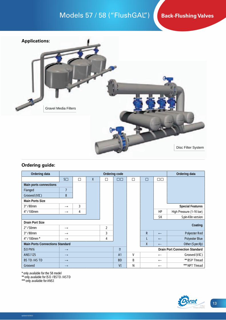
Ordering guide:
Ordering data Ordering code Ordering data5□ □ X □ □□ □ □ □□
Main ports connectionsFlanged 7Grooved (VIC) 8Main Ports Size3" / 80mm → 3 Special Features4" / 100mm → 4 HP High Pressure (1-16 bar)
SK Spin-Klin versionDrain Port Size
Coating2" / 50mm → 23" / 80mm → 3 R ← Polyester Red4" / 100mm * → 4 L ← Polyester BlueMain Ports Connections Standard X ← Other (Specify)ISO PN16 → I1 Drain Port Connection StandardANSI 125 → A1 V ← Grooved (VIC)BS TD / AS TD → BD B ← ** BSP ThreadGrooved → VI N ← *** NPT Thread
* only available for the 58 model** only available for ISO / BSTD / ASTD*** only available for ANSI
Applications:
Disc Filter System
Gravel Media Filters

Back-Flushing Valves
updated 02/2012
Double Chamber Valve Model 51 / 52
14
Dorot Back Flushing Valve- Model 51 & 52
2” Brass body, -3directional, double-chamber valve for back-flushing of filtration batteries
Features:
Simple, compact design•
Double chamber structure•
Non-metallic actuator construction•
Super-fast position change•
In-line maintenance•
Easy installation, no special tools or expertise required.•
Straight or angle flow with easy conversion from one model to •the other, offering maximum flexibility to system design

Back-Flushing Valves
updated 02/2012
Double Chamber Valve Model 51 / 52
15
Operating principle:
Model 51
Model 52
Dimensions & weights:
Inlet / Outlet/ Drain Dimensions mm / inch WeightKg / Lbsmm inch A B C
50 2 155 / 67/8 75 / 215/16 78 / 31/16 3.1 / 6.8
Groove adapters supplied on request.Each groove adapter will add 30 mm (11/8 inch) to the length / height dimensions according to its location.
Threaded connections: Female - NPT / BSP
Drain
Pressurizedcontrol chamber
From filtersInlet
Vented controlchamber
Drain
Inlet To filters
Inlet
From filtersDrain
Pressurizedcontrol chamber
Drain
Inle
t
To filters
Vented controlchamber
Filtration modeControl chamber is de-pressurized - The valve is in filtration mode
Back-Flushing modeControl chamber pressurized - The valve is in flushing mode
B
A
C

Back-Flushing Valves
updated 02/2012
Double Chamber Valve Model 51 / 52
16
Materials:
Part Standard High Pressure Optional1. Bonnet GRP Aluminum SST2. Diaphragm NR NR EPDM3. Spring SST 302 SST 302 SST 3164. Diaphragm discs Brass Brass SST 3165. Screws SST 302 SST 302 SST 3166. Operator Body GRP Brass SST7. Body Brass Brass SST8. Shaft SST 304 SST 304 SST 3169. Plug assy. Brass Brass SST10. Seals NBR NBR Viton
Hydraulic performance:
Model 51 52Size 2 X 2 2 X 2
Max. recommended flow at filtering
m3/h 40 40gpm 176 176
Max. recommended flow at flushing
m3/h 40 40gpm 176 176
Flow rate factor at filtering
Kv (metric) 43 52Cv (US) 50 60
Flow rate factor at flushing
Kv (metric) 40 37Cv (US) 45 43
Operating pressure range:Standard model: 0.7 - 10 bar / 10 - 150 psiHigh Pressure model: 0.7 - 16 bar / 10 - 230 psi
Head loss chart:psi
51, 5
251 52
14
109876
5
4
3
2
109876
5
4
3
2
1
10 20 30 40 50 60 m3/hgpm3002001009080706050
mwc
Filtration modeFlushing mode
1 2 3
14
5
6
7
8
9
10
Maximal operating temperature: Standard models - 60°C (140°F)Hot water model - 90°C (195°F)
Main parts:
Bonnet1.Spring2.Diaphragm & actuator kit3.Body4.Grooved connection adapter5.
1
2
3
4
5

Back-Flushing Valves
updated 02/2012
Double Chamber Valve Model 51 / 52
17
Ordering guide:
Ordering data Ordering code Ordering data5□ 2X2 □ □ □ □ □□
Filtration Flow Direction Special VersionsStraight 1 HW Hot WaterAngle 2 HP High Pressure (16 bar)
CoatingInlet port connectionGrooved adapter → V R ← Polyester RedBSP Thread → B L ← Polyester BlueNPT Thread → N X ← Other (Specify)Outlet port connection Drain port connectionGrooved adapter → V V ← Grooved adapterBSP Thread → B B ← BSP ThreadNPT Thread → N N ← NPT Thread
Sand Media Filter
Double Disc Filters System
Applications:

Back-Flushing Valves
updated 02/2012
Double Chamber Valve Model 62 / 63
18
Dorot Double Chamber Back-Flushing Control Valve, Model 62 & 63
Cast iron, -3directional, double-chamber valve for back-flushing of filtration batteries
Features:
Sturdy body made of cast iron•
Double chamber structure•
High-flow coefficiency allows high flow and low pressure •losses operation.
Super-fast position change•
Easy installation, no special tools or expertise required•
Suitable materials for drinking-water use•
Straight or angle flow with easy conversion from one model to •the other, offering maximum flexibility to system design.

Back-Flushing Valves
updated 02/2012
Double Chamber Valve Model 62 / 63
19
Operating principle:
Dimensions & weights:
Inlet / Outlet Drain Dimensions mm / inch WeightKg / Lbsmm inch mm inch A B C
80 3 50 2 290 / 117/16 168 / 65/8 145 / 511/16 18 / 4080 3 80 3 290 / 117/16 157 / 33/16 145 / 511/16
100 4 80 3 317 / 121/2 200 / 77/8 158 / 61/4 27 / 60100 4 100 4 317 / 121/2 200 / 77/8 158 / 61/4
End connections:Inlet / Outlet - Grooved Drain - Threaded or Grooved. Thread standards: Female NPT / BSP
Model 62
Model 63
D
rain
Drain
Inlet To filters
Vented controlchamber
Inlet From filters
Pressurizedcontrol chamber
Drain
Inle
t
To filters
Inlet
From filtersDrain
Pressurizedcontrol chamberVented control
chamber
Filtration modeControl chamber is de-pressurized - The valve is in filtration mode
Back-Flushing modeControl chamber pressurized - The valve is in flushing mode
C
B
A

Back-Flushing Valves
updated 02/2012
Double Chamber Valve Model 62 / 63
20
Materials:
Part Standard High Pressure1. Bonnet C.I. C.I.2. Diaphragm discs PAGF PAGF3. Bottom chamber PAGF Bronze4. Spring SST 302 SST 3025. Seals NR NR6. Diaphragm NR NR7. Bolts & nuts SST 302 SST 3028. Shaft SST 316 SST 3169. Plug assy. PAGF PAGF10. Seats SST 304 SST 304
Hydraulic performance:
Model 62 & 63Size 4X2 4X3 4X4 3X3 3X2
Max. recommended flow at filtration mode
m3/h 160 90gpm 700 400
Max. recommended flow at back-flushing mode
m3/h 40 90 160 90 40gpm 180 400 700 400 180
Flow rate factor at filtration mode
Kv (metric) 160 100Cv (US) 185 115
Flow rate factor at back-flushing mode
Kv (metric) 110 140 205 145 80Cv (US) 128 163 238 168 93
Operating pressure range:Standard version: 0.5 - 12 bar / 7 - 180 psiHigh Pressure version: 1.0 - 16 bar / 15 - 230 psi*When using 4 way control circuit with external pressure source, no minimal line pressure is requiredMaximum operating temperature: 60°C (140°F)
Head loss chart:
psi
623x
262
3x3,
3x2
633x
363
3x3,
3x4
62 63 4
x4
62 4
x4
63 3
x2 3x3,
3x4
14
109876
5
4
3
2
109876
5
4
3
2
1
30 40 50 60 70 80 90 100 200 m3/hgpm800400300200
mwc
300
Filtration modeFlushing mode
5
4
3
2
16
8
9
10
7
Main parts:
Bonnet1.Diaphragm and 2.actuator kitSeat3.O-ring4.Body5.O-ring6.Seat7.O-ring8.Connection adapter9.
1
2
3
4
5
6
7
8
9

Back-Flushing Valves
updated 02/2012
Double Chamber Valve Model 62 / 63
21
Ordering guide:
Ordering data Ordering code Ordering data6□ □ X □ □ □ □□
Flow direction at filteringStraight 2 Special FeaturesAngle 3 HP High Pressure Model (16 bar)Top Ports Size Coating4” / 100mm → 4 L ← Polyester Blue3” / 80mm → 3 R ← Polyester Red
X ← Other (specify)Bottom Port Size Drain port connection4" / 100mm → 4 V ← Grooved (VIC)3" / 80mm → 3 B ← BSP Thread2" / 50mm → 2 N ← NPT Thread
Applications:
Sand Media Filters
Disc Filter System

Back-Flushing Valves
updated 02/2012
Double Chamber Valve Model 09 (“Galil”)
22
Dorot Double Chamber 2” Valve - Model 09 (“Galil”)
Brass body, Double-chamber control valve, made to enable automatic backflush of screen filters.
Features:
A sturdy body made of Brass (SST optional)•
Double chamber control•
In-line maintenance•
Fast reaction•
Easy installation, no special tools or expertise required•
Configurable to “Normally Open” or “Normally Closed” operation•
Optional manual throttling•
Straight (model 09) or angle (model 09-A) flow•

Back-Flushing Valves
updated 02/2012
Double Chamber Valve Model 09 (“Galil”)
23
Operating principle:
Standard model Normally Open model
Dimensions & weights:
Model TypeDimensions mm / inch Weight
Kg / LbsA B C09 Straight 196 / 711/16 193 / 75/8 125 / 415/16
3.2 / 709 + throttling handle Straight 235 / 91/4 219 / 85/8 125 / 415/16
09-A Angle 192 / 79/16 130 / 51/8 66 / 25/8
09-A + throttling handle Angle 260 / 101/4 130 / 51/8 66 / 25/8
Threaded connections: Female - NPT / BSP
Vented controlchamber
Pressurizedcontrol chamber
Inlet Outlet Inlet Outlet
Vented cont rolcham ber
Pressurizedcont rol cham ber
Inlet Out let Inlet Out let
P ressurizedcont rol cham ber
Inlet Out let
Vented cont rolcham ber
Inlet Out let
Vented cont rolcham ber
Inlet Out let
P ressurizedcont rol cham ber
Inlet Out let
Normally Closed model (Reverse Flow)Normally Closed model (Normal Flow)
Closed valve Open valve Closed valve Open valve
Closed valve Open valve Closed valve Open valve
A
C
B
C
A
B

Back-Flushing Valves
updated 02/2012
Double Chamber Valve Model 09 (“Galil”)
24
Materials:
Part Standard model
High Pressure model
Hot water model
Sea water model *
1. Body Brass Brass Brass SST 3162. Bonnet PAGF AL AL SST 3163. Actuator housing PAGF Brass Brass SST 3164. Shaft SST 302 SST 302 SST 302 SST 3165. Spring SST 302 SST 302 SST 302 SST 3166. Screws Steel Steel Steel SST 3167. Seals NR NR Viton / EPDM NR8. Diaphragm NR NR EPDM NR
*In Angle pattern only
Hydraulic performance:
Size 2”
Max. recommended flow ratem3/h 40gpm 176
Flow rate factor
Model 09Kv (metric) 35
Cv (US) 41
Model 09-AKv (metric) 55
Cv (US) 65
Operating pressure range:Standard version: 1 - 10 bar / 14.5 - 145 psiHigh Pressure version: 1 - 16 bar / 14.5 - 230 psiMaximum operating temperature: Standard model - 60°C (140°F) Hot water model - 90°C (195°F)
Head loss chart:
psi
09 09-A
N
14
109876
5
4
3
2
109876
5
4
3
2
1
10 20 30 40 50 60 m3/hgpm3002001009080706050
mwc
1
2
3
4
5
6
7
8
2
1
3
4
Main parts:
Bonnet1.Spring2.Operator kit3.Body4.

Back-Flushing Valves
updated 02/2012
Double Chamber Valve Model 09 (“Galil”)
25
Ordering guide:
Ordering data Ordering code Ordering data09 □ □ -2- □□ □□ □□ □□ □□
Valve bodyStraight flow → -Angle flow → A Special FeaturesTrottling handle WB Wide Body versionWithout → - HP High Pressure (16 bar)With → T
IN Indicator rod (supplied with metalic bonnet)
Connections Standard HW Hot WaterBSP Threads → BS RS Low-Pressure SealNPT Threads → NP PC Conic PlugFunction S0 No SpringStandard → - XS Stiff SpringNormaly Close → NC CoatingNormaly Open → NO - ← UncoatedFlow direction CR ← Polyester RedNormal (under the seat) → - CB ← Polyester BlueReverse (over the seat) → RF X ← Other (Specify)
Applications:
Automatic Screen Filter
Sand-Separator (Hydrocyclone) System

Back-Flushing Valves
updated 02/2012
Normally Closed Valve Model 60
26
Dorot Normally Closed Valve Model 60
Features:
High resistance to corrosive fluids•Normally-Closed operation•Fast reaction•Easy installation and maintenance•Tough and durable construction•Drip-tight sealing at zero pressure•Angle pattern minimizes pressure losses•
Operating principle:
Closed valve Open valve
Dimensions & weights:
SizeDimensions mm / inch Weight
Kg / LbsA B C40mm / 1.5” 164 / 67/16 127 / 5 89 / 31/2 0.7 / 1.6
Threaded connections:Inlet Female, Outlet male - NPT / BSP
Materials:Part Standard model Mining model
1. Body PPGF PPGF2. Bonnet PPGF PPGF3. Shaft PPGF PPGF4. Spring SST 302 SST 3165. Screws SST 304 SST 3046. Seals EPDM ALD and Viton7. Diaphragm EPDM ALD
Hydraulic performance:Size 11/2”
Max. recommended flow ratem3/h 25gpm 110
Flow rate factorKv (metric) 25
Cv (US) 30
Pressurized control chamber
Inlet
Outlet
Vented control chamber
Inlet
Outlet
A
C
B
Operating pressure range:Standard version: 0.4 – 8 bar / 6 – 115 psiMaximal operating temperature: 60°C (140°F)Minimal command pressure: 0.4 bar, will be at least 60% of line pressure
2
3
4
5
6
7 1

Back-Flushing Valves
updated 02/2012
Normally Closed Valve Model 60
27
Main parts:
Body1.O-ring2.Diaphragm assembly3.Bonnet4.Bolt5.Washer6.Nut7.ID.Plate8.Ring9.
Ordering guide:
Ordering data Ordering code Ordering data60-ANC □□ □□
Connection standard Special FeaturesNPT → NP ST StandardBSP → BS MI Mining
Sand Separator (Hydrocyclone) Systems Automatic Screen / Disc Filters
Applications:

Back-Flushing Valves
updated 02/2012
Models S-300, S-500, S-100
28
Models S-300, S-500, S-100
Hydraulic control valves of series S-300, S-500 and S-100 are frequently assembled in filtration systems as regulating valves (Pressure Reducing / Sustaining, Flow Control), as safety valves (Quick Relief), or as a part of the automatic flushing system.Detailed engineering and technical data for these models are available in the relevant DOROT catalogues.
Filtration Disk System
S-100 S-300 S-500

Back-Flushing Valves
updated 02/2012
Models S-300, S-500, S-100
29
Sand Media Filter
Sand Media Filters

Back-Flushing Valves
updated 02/2012
Special Applications for Filtration Systems
30
5 valves array for high flow media filters:
1
2
3
4
5
Inlet
Outlet
Back flushcontroller
Drain
Each valve is controlled by a solenoid, connected to the back-flushing controller.
At filtration mode, no electric command is supplied: valves [1] •and [2] are open to allow flow, and valves [3,4,5] are closed.At flushing mode, valves [1,2] are energized to close and valves •[3,4] are energized to open, flushing the filter to the drain line.As flushing time elapses, valves [3,4] are de-energized to close, •valve [1] is de-energized to open and valve [5] is energized to open, pressing the media and directing the initial, “dirty stage” of filtered water, to the drain.Valve [5] is de-energized to close, valve [2] is de-energized to •open, system returns to filtering mode.Solenoid valves may be assembled on the valves (Application •code: EL) or on a common bracket, activating the valves by pressure tubes (Application code: RC model).
Typical Models:
Regulation of flushing flow rate in media filtration batteries
The pressure differential between the filter’s internal pressure and atmospheric pressure may reach a point where flow rates during flushing are significantly high. This may carry out the media through the drain port of the filter (which is costly) and may increase the risk for pressure surges. Electrically controlled Flow Regulating valves, prevent these undesired situations. The valves are controlled by a solenoid-valve, actuated by the back-flush controller.
At filtration mode, no electric command is supplied: valve [1] is •fully open and the flow regulating valve [2] is closed.At flushing mode, valve [1] is energized to close and the flow •regulating valve [2] is energized to open while limiting the flushing flow rate to a desired maximal level.Application codes: EL, FR/EL•
Typical Models:
Outlet
1
Inlet
Commonoutlet
Manifold
2
Drain
Back flushcontroller
50-4-EL47-4-RC
47-4-FR/EL 50-4-FR/EL

Back-Flushing Valves
updated 02/2012
Special Applications for Filtration Systems
31
Regulation of flushing flow rate in Disc Filtration Batteries
Outlet
Inlet1
Back flushcontroller
Drain
Automatic filtration systems require minimal pressure to ensure appropriate flushing, and may not function properly at too-low pressure. During the flushing procedure, system pressure may drop significantly. The electrically controlled, Pressure Sustaining Normally Open (PSNO) valve [1] is fully open during the filtration mode; enabling minimal pressure losses on the supply line to the users. The valve will start regulating to sustain a minimal pressure in its upstream side when receiving an electric command from the back-flushing controller.Combining the PSNO valve in the filtration system enables working with lower pressures during normal supply water while ensuring sufficient pressure for back flushing.
Application code: PSNO•
Typical Models:
Flushing Pressure-Differential Control in Automatic Screen Filters
During the flushing procedure of an automatic screen filter, a high pressure differential is generated on the screen by the suction nozzles.The force applied by this pressure differential may cause the screen to collapse and ruin the filter.The Pressure Differential Reducing application added to the Flushing valve [1] limits the pressure differential between the hydraulic motor chamber and dirt collector (the valve inlet) and the filter outlet port, to a safe, adjustable value, thus preventing collapse and damage to the filter.
Application code: PD •
Typical Models:
1
Inlet Outlet
Drain
47-6-PSNO 96-6-PSNO
30A-2-PD 50A-2-PD

Hundreds of companies in the industrial, civil engineering
and agricultural sectors around the world have
selected the innovative and field-proven technologies
developed by Dorot. Public and private water utility
companies, construction and engineering companies,
fire-suppression integrators, farming enterprises, energy
companies and other entities from various industries, all
benefit from Dorot’s expertise and professional services.
Dorot is considered a true partner by its customers for
overcoming challenges in R&D, design, implementation,
and maintenance of water-control valve products.
Since its establishment in 1946, Dorot drives the market
with continued innovation, uncompromising excellence
and firm commitment to its customers. Through its
unique water-management solutions, the company
also contributes to the global efforts for environment
protection. Dorot invests in research and development of
quality products and solutions. w w w. d o r o t . c o m