back to the future time circuit 3d printed clock
TRANSCRIPT

Back to the Future Time Circuit 3D Printed Clock
November 2015
Back to the Future Time Circuit 3D Printed Clock Construction

Back to the Future Time Circuit 3D Printed Clock Construction Information
Issue Date: November 4, 2015 Version 1.0
Page 2 of 85
1 DISCLAIMER 4
1 OVERVIEW 5
2 COMPONENTS 6
2.1 ARDUINO UNO R3 CONTROLLER 6 2.2 ARDUINO PROTO SCREWSHIELD 7 2.4 CHRONODOT REAL TIME CLOCK 8 2.5 MUSIC MAKER MP3 SHIELD 9 2.6 AUDIO SPEAKERS 10 2.7 LED DISPLAYS 11 2.8 SN74HC138N 3 – 8 LINE DECODER 13 2.9 RGB LCD SHIELD 14 2.10 AM / PM LEDS 15 2.11 POWER SUPPLY 16 2.12 PANEL MOUNT 2.1 MM DC BARREL JACK 17 2.13 LM7805 VOLTAGE STABILIZER 18 2.14 PERMA-PROTO BREADBOARD 19 2.15 FILAMENT 20 2.16 WIRE 21 2.17 PAINT 22 2.18 SCREWS / WASHERS 23
3 CLOCK DECALS / DESIGN 25
4 3D PRINTING 27
5 CONSTRUCTION 45
5.1 GLUE THE TOP, FRONT AND BOTTOM HALVES 45 5.2 GLUE THE FRONT HALVES 46 5.3 GLUE THE TOP HALVES 47 5.4 GLUE THE BACK HALVES 47 5.5 GLUE THE BOTTOM HALVES 49 5.6 DRILL GUIDE HOLES FOR LED DISPLAYS 50 5.7 DRILL / EXPAND LED MOUNTING HOLES 51 5.8 DRILL GUIDE HOLES FOR RGB LCD DISPLAY 52 5.9 DRILL / EXPAND RGB LCD PUSHBUTTON / CONTRAST HOLES 53 5.10 LAYOUT THE LEFT AND RIGHT SIDES 54 5.11 INSERT THE SPEAKER COVERS AND SPEAKERS 55 5.12 GLUE THE ENCLOSURE 56 5.13 ASSEMBLE THE ENCLOSURE 57 5.14 PREPARE THE ENCLOSURE FOR PAINTING 59 5.15 PAINT ENCLOSURE 61 5.16 ASSEMBLE MUSIC MAKER 63 5.17 WIRE AND MOUNT THE 4 DIGIT LED DISPLAYS 64 5.18 WIRE AND MOUNT AM/PM LEDS 65
Back to the Future Time Circuit 3D Printed Clock Construction Information
Issue Date: November 4, 2015 Version 1.0
Page 3 of 85
5.19 MOUNT THE VOLTAGE STABILIZER 66 5.20 MOUNT THE ARDUINO UNO 67 5.21 MOUNT THE RGB LCD DISPLAY 68 5.22 WIRING DIAGRAM 69 5.23 WIRE THE PERMA-PROTO BOARD 70 5.24 WIRE THE SCREWSHIELD 70 5.25 INSTALL ARDUINO AND SCREWSHIELD 70 5.26 INSTALL MUSIC MAKER ON SCREWSHIELD 71 5.27 MOUNT /WIRE DC BARREL CONNECTOR 72 5.28 INSTALL DECALS 73 5.29 ATTACH BASE / BUMPERS 75 5.30 MAKE POWER CONNECTION 76
6 RGB LCD OPERATION 77
7 TIME DISPLAYS 81
8 TIME ANNOUNCEMENT 82
9 POWER UP SEQUENCE 83
10 PARTS LISTING 84

Back to the Future Time Circuit 3D Printed Clock Construction Information
Issue Date: November 4, 2015 Version 1.0
Page 4 of 85
1 DISCLAIMER
This document and the attached drawings are not to be used for construction. You are hereby authorized to view, copy, print, and distribute the materials from this document or the attached drawings subject to the following conditions:
The materials are for your personal informational use only and not for commercial purposes.
No liability in respect of any of the contents of such publications or use thereof is accepted and no warranties expressed or implied are made in relation thereto.
Disclaimer ANY INFORMATION CONTAINED IN THIS DOCUMENT OR THE ATTACHED DRAWINGS ARE PROVIDED [AS IS] FOR YOUR INFORMATIONAL PURPOSES ONLY, WITHOUT WARRANTY OF ANY KIND, INCLUDING ANY IMPLIED WARRANTY OF MERCHANTABILITY, FITNESS FOR A PARTICULAR PURPOSE, OR NON-INFRINGEMENT. THE AUTHOR OF THIS DOCUMENT AND ATTACHED DRAWINGS WILL IN NO EVENT BE LIABLE FOR ANY DIRECT, INDIRECT OR PUNITIVE DAMAGE OF ANY KIND THAT RESULTS FROM THE USE OF OR INABILITY TO USE THIS DOCUMENT OR THE ATTACHED DRAWINGS, INCLUDING WITHOUT LIMITATION, LOSS OF PROFITS, GOODWILL, OR BUSINESS INTERRUPTION. THE AUTHOR OFFERS NO ASSURANCES, WARRANTIES OR GUARANTEES AS TO THE VALIDITY OR COMPLETENESS OF THIS INFORMATION. INFORMATION WILL BE CHANGED, UPDATED AND DELETED WITHOUT NOTICE.
Back to the Future Time Circuit 3D Printed Clock Construction Information
Issue Date: November 4, 2015 Version 1.0
Page 5 of 85
1 Overview
The time circuit clock will display the following via the LED displays. Destination Time – (Top-Red) The destination time is an area that shows a fixed date and time. Use this area to display an important date in your life such as wedding, Birthday or the date you first discovered this most excellent clock. Present Time – (Middle-Green) The present time is the current date and time. You set this initially when you download the Arduino and you can adjust the hour and minute via the RGB LCD display keypad. Last Time Departed – (Bottom-Yellow) The last time departed will alternate between three different important dates every 20 seconds. Use this for birthdays, the date you finished building the clock, the day you met your significant other, etc. The time circuit will announce the time between the hours of 8:00 AM and 9:30 PM. The time is generated via the Music Maker MP3 shield. The audio files for the time announcement were recorded by my wife and are included. To enhance the clock further, I enlisted a voice impersonator that recorded the time announcements as Doc Browns voice. Contact information for the voice impersonator is included in this “Instructable”. Power on message and time announce files are provided. You can change these by simply by recording new .mp3 files and putting them on the music maker board micro SD card. The clock is 3D printed and utilizes (1) Arduino Uno, (1) Music Maker MP3 shield, (1) ChronoDot real time clock, (1) RGB LCD keypad, (9) 3 mm LEDs, (1) voltage isolator and a few other components. A complete parts list along is provided at the end of this “Instructable”. The .stl files for printing the clock parts, Arduino code, wiring diagram, decal template and the audio files are located here. The clock was printed on a Lulzbot mini which has a print bed size of 150 mm x 150 mm. The entire clock was printed with HIPS filament with the exception of the pushbutton extensions that were printed with black ABS filament.

Back to the Future Time Circuit 3D Printed Clock Construction Information
Issue Date: November 4, 2015 Version 1.0
Page 6 of 85
2 Components
The Clock is controlled by an Arduino microcontroller. The Arduino handles the interface to (9) four digit LED displays, (6) AM/PM LEDs, (1) MP3 Music Maker Shield, (1) RGB LCD pushbutton display and a Chronodot real time clock.
2.1 Arduino Uno R3 Controller The clock utilizes an Arduino Uno R3 controller. The Arduino Uno R3 is programmed to monitor and control the entire clock. The Arduino Uno can be purchased at Adafruit.com http://www.adafruit.com/products/50
Figure 2.11 – Arduino Uno R3
Arduino Uno
Power Jack 7 VDC – 12 VDC
Programming Port
Back to the Future Time Circuit 3D Printed Clock Construction Information
Issue Date: November 4, 2015 Version 1.0
Page 7 of 85
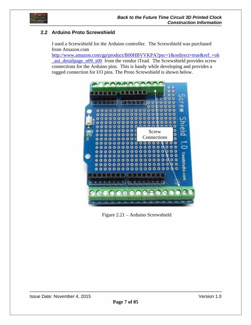
2.2 Arduino Proto Screwshield I used a Screwshield for the Arduino controller. The Screwshield was purchased from Amazon.com http://www.amazon.com/gp/product/B00HBVVKPA?psc=1&redirect=true&ref_=oh_aui_detailpage_o09_s00 from the vendor iTead. The Screwshield provides screw connections for the Arduino pins. This is handy while developing and provides a rugged connection for I/O pins. The Proto Screwshield is shown below.
Figure 2.21 – Arduino Screwshield
Screw Connections
Back to the Future Time Circuit 3D Printed Clock Construction Information
Issue Date: November 4, 2015 Version 1.0
Page 8 of 85
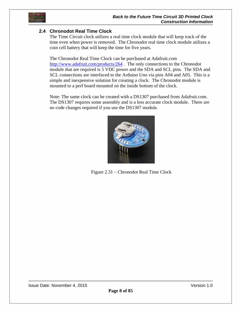
2.4 Chronodot Real Time Clock The Time Circuit clock utilizes a real time clock module that will keep track of the time even when power is removed. The Chronodot real time clock module utilizes a coin cell battery that will keep the time for five years. The Chronodot Real Time Clock can be purchased at Adafruit.com http://www.adafruit.com/products/264 . The only connections to the Chronodot module that are required is 5 VDC power and the SDA and SCL pins. The SDA and SCL connections are interfaced to the Arduino Uno via pins A04 and A05. This is a simple and inexpensive solution for creating a clock. The Chronodot module is mounted to a perf board mounted on the inside bottom of the clock. Note: The same clock can be created with a DS1307 purchased from Adafruit.com. The DS1307 requires some assembly and is a less accurate clock module. There are no code changes required if you use the DS1307 module.
Figure 2.31 – Chronodot Real Time Clock
Back to the Future Time Circuit 3D Printed Clock Construction Information
Issue Date: November 4, 2015 Version 1.0
Page 9 of 85
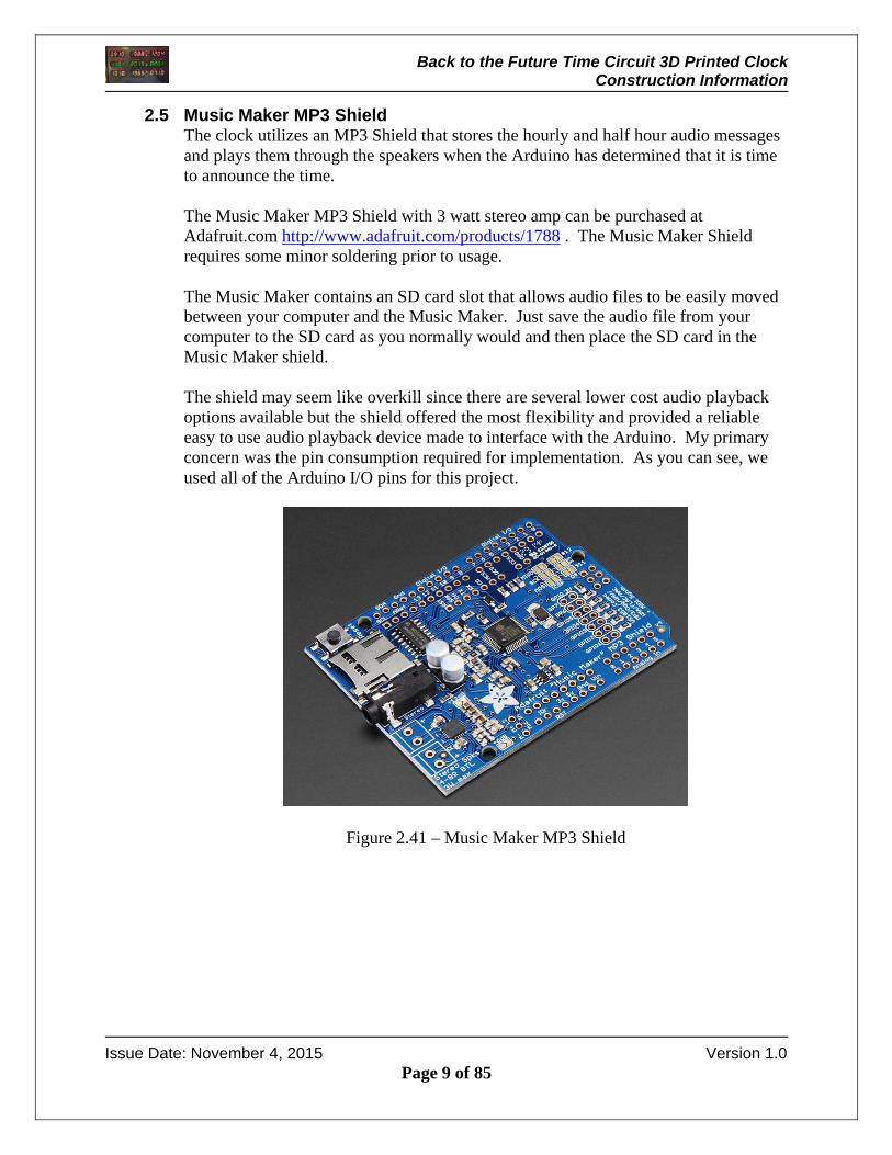
2.5 Music Maker MP3 Shield The clock utilizes an MP3 Shield that stores the hourly and half hour audio messages and plays them through the speakers when the Arduino has determined that it is time to announce the time. The Music Maker MP3 Shield with 3 watt stereo amp can be purchased at Adafruit.com http://www.adafruit.com/products/1788 . The Music Maker Shield requires some minor soldering prior to usage. The Music Maker contains an SD card slot that allows audio files to be easily moved between your computer and the Music Maker. Just save the audio file from your computer to the SD card as you normally would and then place the SD card in the Music Maker shield. The shield may seem like overkill since there are several lower cost audio playback options available but the shield offered the most flexibility and provided a reliable easy to use audio playback device made to interface with the Arduino. My primary concern was the pin consumption required for implementation. As you can see, we used all of the Arduino I/O pins for this project.
Figure 2.41 – Music Maker MP3 Shield
Back to the Future Time Circuit 3D Printed Clock Construction Information
Issue Date: November 4, 2015 Version 1.0
Page 10 of 85
2.6 Audio Speakers
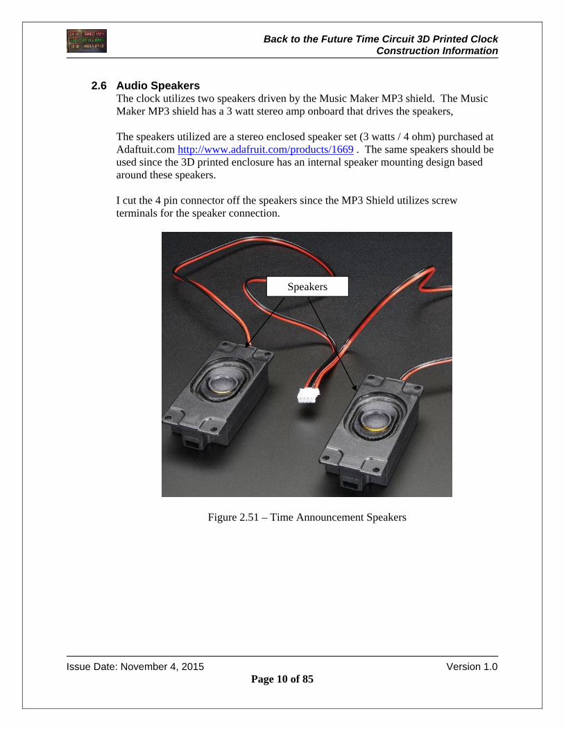
The clock utilizes two speakers driven by the Music Maker MP3 shield. The Music Maker MP3 shield has a 3 watt stereo amp onboard that drives the speakers, The speakers utilized are a stereo enclosed speaker set (3 watts / 4 ohm) purchased at Adaftuit.com http://www.adafruit.com/products/1669 . The same speakers should be used since the 3D printed enclosure has an internal speaker mounting design based around these speakers. I cut the 4 pin connector off the speakers since the MP3 Shield utilizes screw terminals for the speaker connection.
Figure 2.51 – Time Announcement Speakers
Speakers
Back to the Future Time Circuit 3D Printed Clock Construction Information
Issue Date: November 4, 2015 Version 1.0
Page 11 of 85
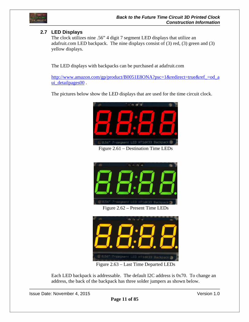
2.7 LED Displays The clock utilizes nine .56” 4 digit 7 segment LED displays that utilize an adafruit.com LED backpack. The nine displays consist of (3) red, (3) green and (3) yellow displays. The LED displays with backpacks can be purchased at adafruit.com http://www.amazon.com/gp/product/B0051E8ONA?psc=1&redirect=true&ref_=od_aui_detailpages00 . The pictures below show the LED displays that are used for the time circuit clock.
Figure 2.61 – Destination Time LEDs
Figure 2.62 – Present Time LEDs
Figure 2.63 – Last Time Departed LEDs
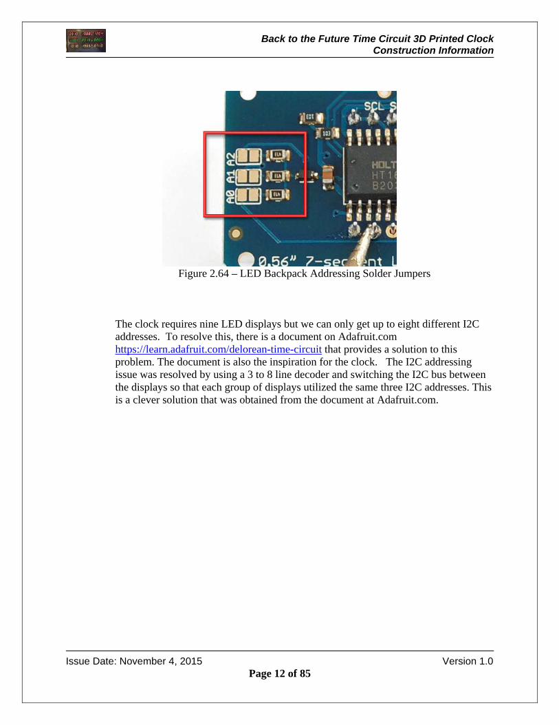
Each LED backpack is addressable. The default I2C address is 0x70. To change an address, the back of the backpack has three solder jumpers as shown below.
Back to the Future Time Circuit 3D Printed Clock Construction Information
Issue Date: November 4, 2015 Version 1.0
Page 12 of 85
Figure 2.64 – LED Backpack Addressing Solder Jumpers
The clock requires nine LED displays but we can only get up to eight different I2C addresses. To resolve this, there is a document on Adafruit.com https://learn.adafruit.com/delorean-time-circuit that provides a solution to this problem. The document is also the inspiration for the clock. The I2C addressing issue was resolved by using a 3 to 8 line decoder and switching the I2C bus between the displays so that each group of displays utilized the same three I2C addresses. This is a clever solution that was obtained from the document at Adafruit.com.
Back to the Future Time Circuit 3D Printed Clock Construction Information
Issue Date: November 4, 2015 Version 1.0
Page 13 of 85
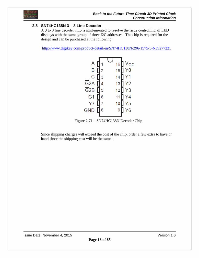
2.8 SN74HC138N 3 – 8 Line Decoder A 3 to 8 line decoder chip is implemented to resolve the issue controlling all LED displays with the same group of three I2C addresses. The chip is required for the design and can be purchased at the following: http://www.digikey.com/product-detail/en/SN74HC138N/296-1575-5-ND/277221
Figure 2.71 – SN74HC138N Decoder Chip
Since shipping charges will exceed the cost of the chip, order a few extra to have on hand since the shipping cost will be the same:

Back to the Future Time Circuit 3D Printed Clock Construction Information
Issue Date: November 4, 2015 Version 1.0
Page 14 of 85
2.9 RGB LCD Shield The RGB LCD shield is used to display the date / time as well as change the hours and minutes for the clock. The RGB LCD shield is a handy way to easily change the time for daylight savings time without the need to download the program to set the correct time. The shield interfaces with the Arduino via the I2C buss. The five pushbuttons located on the left hand side of the shield are used to set the hours, minutes and allow the display to be turned off and on. The pushbuttons use the same I2C buss as the display. The shield is not attached to the Arduino since it only requires power and the two I2C wires (SDA and SCL). The shield can display the text as Red, Teal, Violet, Yellow and several other colors. The RGB LCD Shield can be purchased at adafruit.com http://www.adafruit.com/products/714
Figure 2.81 – RGB LCD Shield
Pushbuttons
Contrast

Back to the Future Time Circuit 3D Printed Clock Construction Information
Issue Date: November 4, 2015 Version 1.0
Page 15 of 85
2.10 AM / PM LEDs Each row on the clock has an AM and PM LED. The top row utilizes (2) 3 mm red LEDs, the middle row utilizes (2) 3 mm green LEDs and the bottom row utilizes (2) yellow 3 mm LEDs. The LEDs can be purchased at your local Radio Shack or Amazon.com. The LEDs used in this unit were purchased at Amazon.com http://www.amazon.com/gp/product/B0087ZT1VO?keywords=3%20mm%20led&qid=1445881847&ref_=sr_1_4&sr=8-4 The picture below shows the LEDs.
Figure 2.91 – Red, Yellow and Green 3 mm LEDs
Back to the Future Time Circuit 3D Printed Clock Construction Information
Issue Date: November 4, 2015 Version 1.0
Page 16 of 85
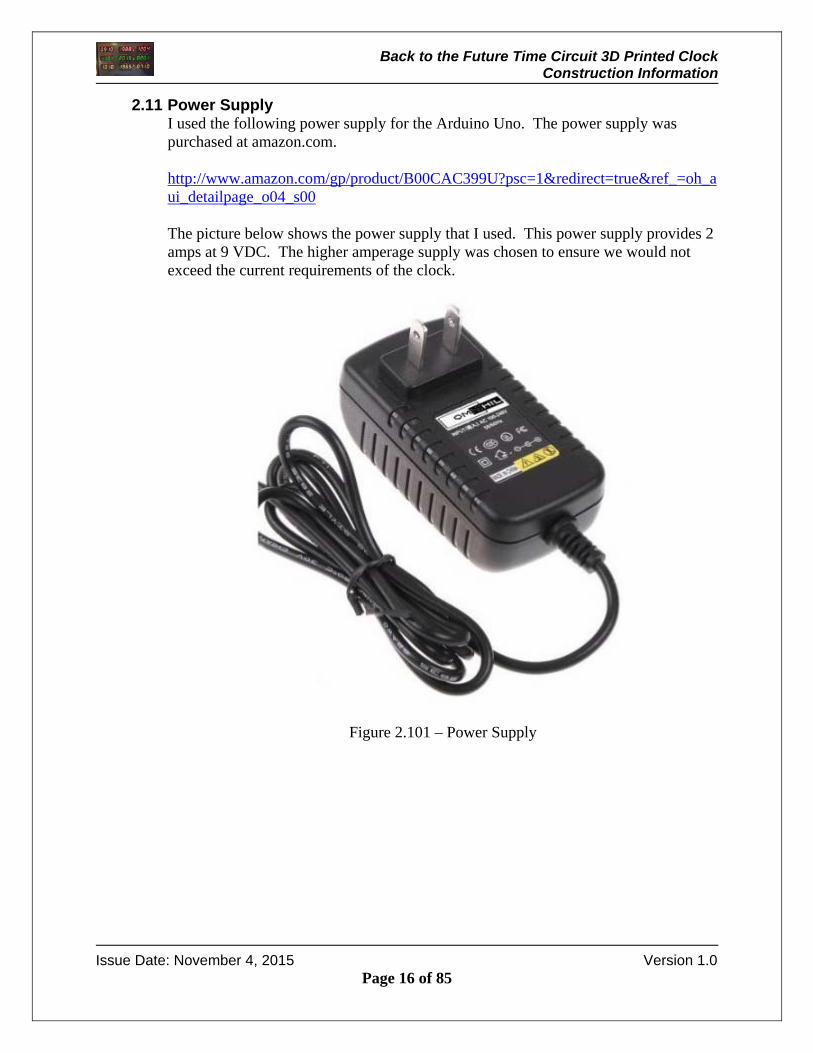
2.11 Power Supply I used the following power supply for the Arduino Uno. The power supply was purchased at amazon.com. http://www.amazon.com/gp/product/B00CAC399U?psc=1&redirect=true&ref_=oh_aui_detailpage_o04_s00 The picture below shows the power supply that I used. This power supply provides 2 amps at 9 VDC. The higher amperage supply was chosen to ensure we would not exceed the current requirements of the clock.
Figure 2.101 – Power Supply

Back to the Future Time Circuit 3D Printed Clock Construction Information
Issue Date: November 4, 2015 Version 1.0
Page 17 of 85
2.12 Panel Mount 2.1 MM DC Barrel Jack I used a 2.1 mm jack for the power connection to the clock. The power feed to the jack is split inside the clock to the Arduino Uno and a voltage stabilizer. The DC Barrel jack was purchased at Adafruit.com http://www.adafruit.com/products/610 The picture below shows the DC barrel jack that is used.
Figure 2.111 – DC Barrel Jack
Back to the Future Time Circuit 3D Printed Clock Construction Information
Issue Date: November 4, 2015 Version 1.0
Page 18 of 85
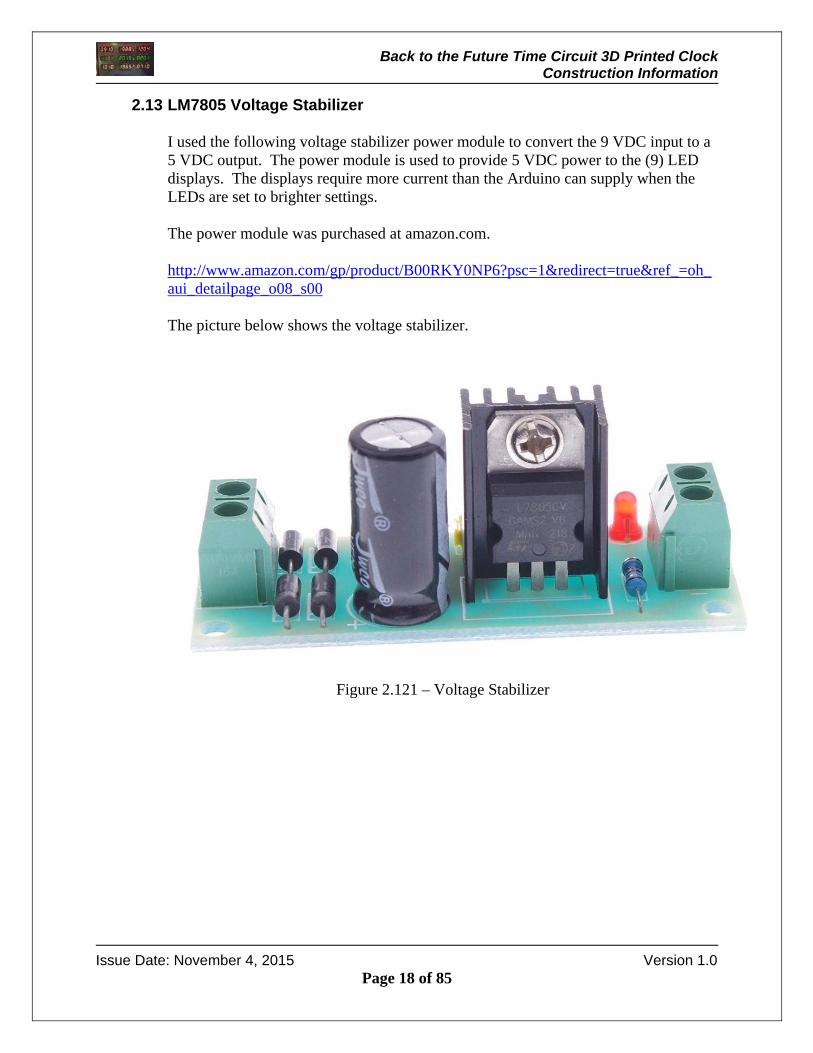
2.13 LM7805 Voltage Stabilizer
I used the following voltage stabilizer power module to convert the 9 VDC input to a 5 VDC output. The power module is used to provide 5 VDC power to the (9) LED displays. The displays require more current than the Arduino can supply when the LEDs are set to brighter settings. The power module was purchased at amazon.com. http://www.amazon.com/gp/product/B00RKY0NP6?psc=1&redirect=true&ref_=oh_aui_detailpage_o08_s00 The picture below shows the voltage stabilizer.
Figure 2.121 – Voltage Stabilizer

Back to the Future Time Circuit 3D Printed Clock Construction Information
Issue Date: November 4, 2015 Version 1.0
Page 19 of 85
2.14 Perma-Proto Breadboard
I soldered the ChronotDot and the 3 to 8 line decoder chip socket onto the Adafruit half-sized breadboard. The Perma-Proto breadboard was purchased at adafruit.com, http://www.adafruit.com/products/1609 The picture below shows the breadboard.
Figure 2.131 – Perma-Proto Half-Sized Breadboard
Back to the Future Time Circuit 3D Printed Clock Construction Information
Issue Date: November 4, 2015 Version 1.0
Page 20 of 85
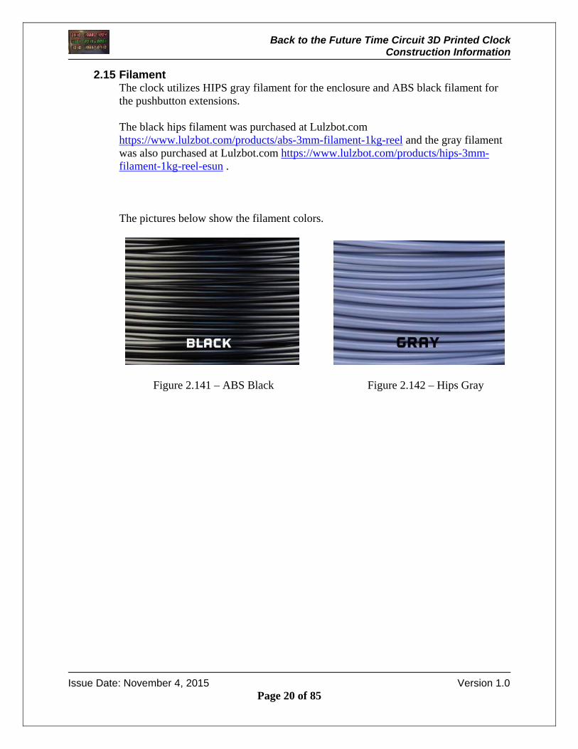
2.15 Filament The clock utilizes HIPS gray filament for the enclosure and ABS black filament for the pushbutton extensions. The black hips filament was purchased at Lulzbot.com https://www.lulzbot.com/products/abs-3mm-filament-1kg-reel and the gray filament was also purchased at Lulzbot.com https://www.lulzbot.com/products/hips-3mm-filament-1kg-reel-esun . The pictures below show the filament colors.
Figure 2.141 – ABS Black Figure 2.142 – Hips Gray
Back to the Future Time Circuit 3D Printed Clock Construction Information
Issue Date: November 4, 2015 Version 1.0
Page 21 of 85
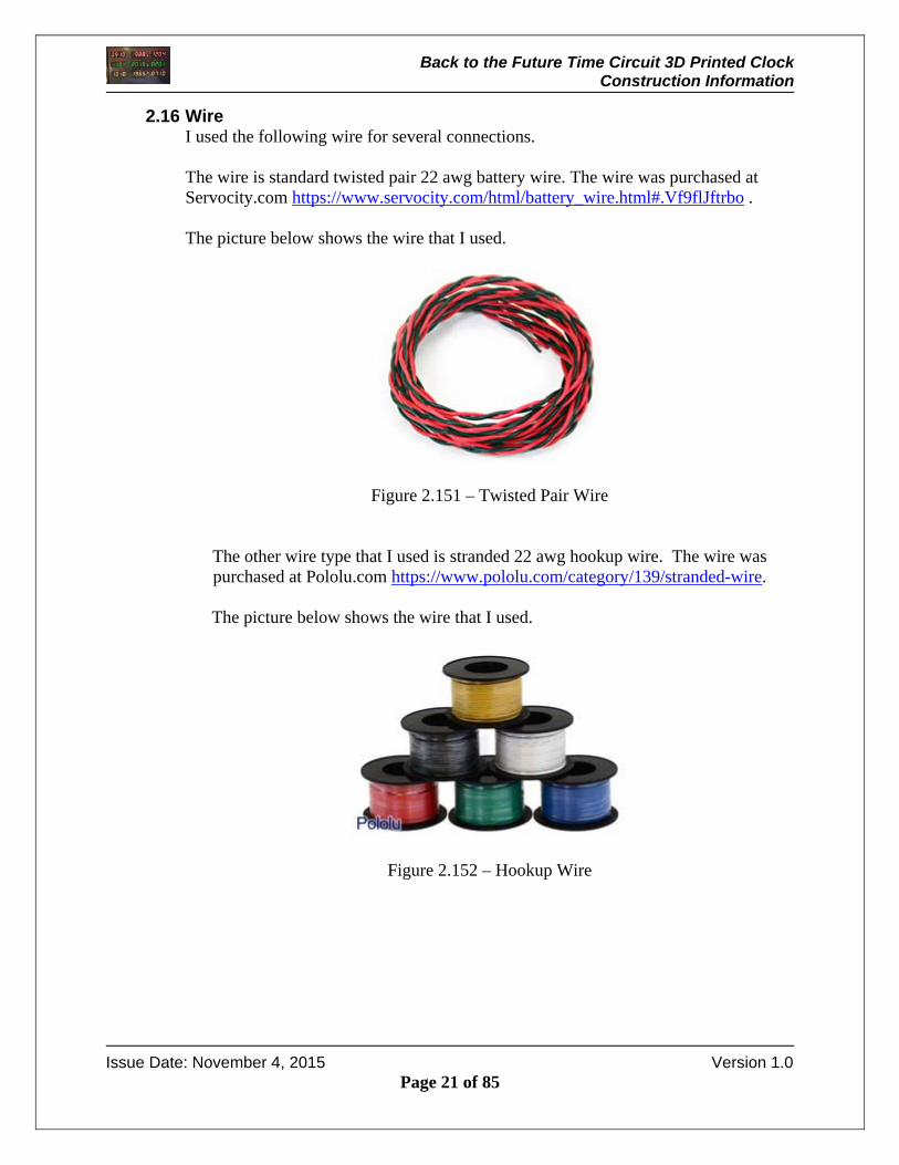
2.16 Wire I used the following wire for several connections. The wire is standard twisted pair 22 awg battery wire. The wire was purchased at Servocity.com https://www.servocity.com/html/battery_wire.html#.Vf9flJftrbo . The picture below shows the wire that I used.
Figure 2.151 – Twisted Pair Wire
The other wire type that I used is stranded 22 awg hookup wire. The wire was purchased at Pololu.com https://www.pololu.com/category/139/stranded-wire.
The picture below shows the wire that I used.
Figure 2.152 – Hookup Wire
Back to the Future Time Circuit 3D Printed Clock Construction Information
Issue Date: November 4, 2015 Version 1.0
Page 22 of 85
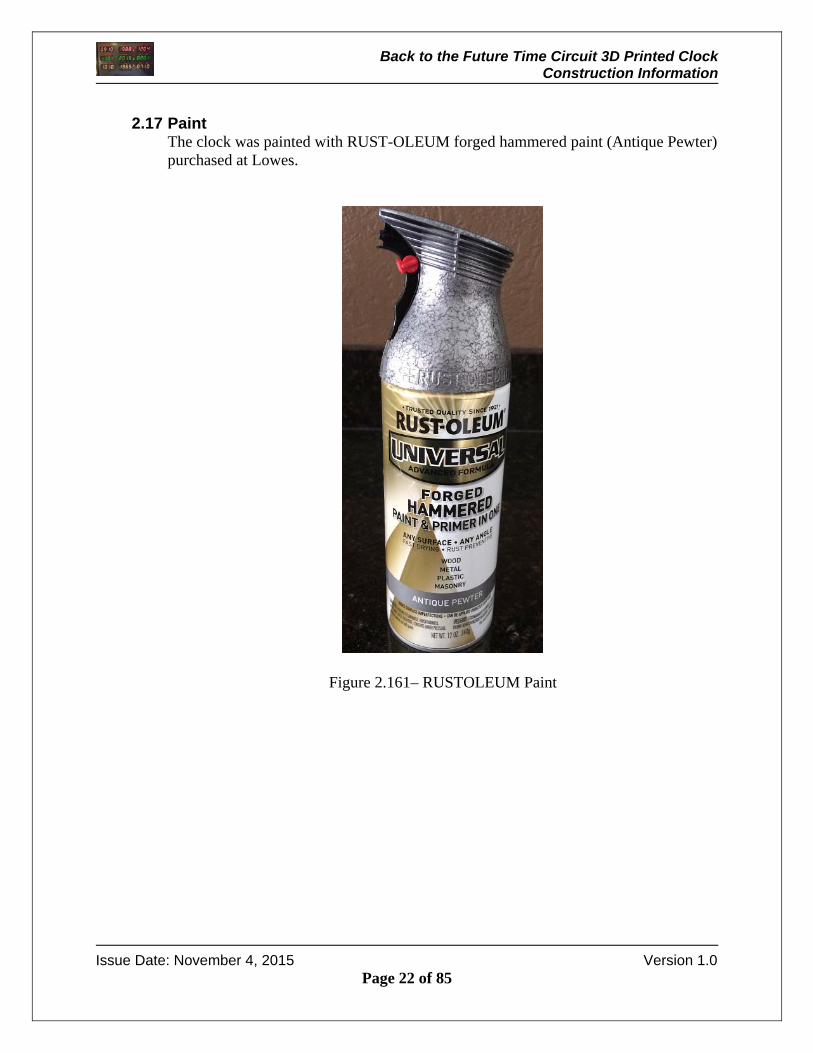
2.17 Paint
The clock was painted with RUST-OLEUM forged hammered paint (Antique Pewter) purchased at Lowes.
Figure 2.161– RUSTOLEUM Paint

Back to the Future Time Circuit 3D Printed Clock Construction Information
Issue Date: November 4, 2015 Version 1.0
Page 23 of 85
2.18 Screws / Washers I used #2 x 3/8 inch Philips screws with washers for mounting the LED assemblies to the enclosure. I also used the same screws in ½” length for mounting the RGB display. The screws can be purchased at Lowes.
Figure 2.171 – Mounting Screws
Back to the Future Time Circuit 3D Printed Clock Construction Information
Issue Date: November 4, 2015 Version 1.0
Page 24 of 85
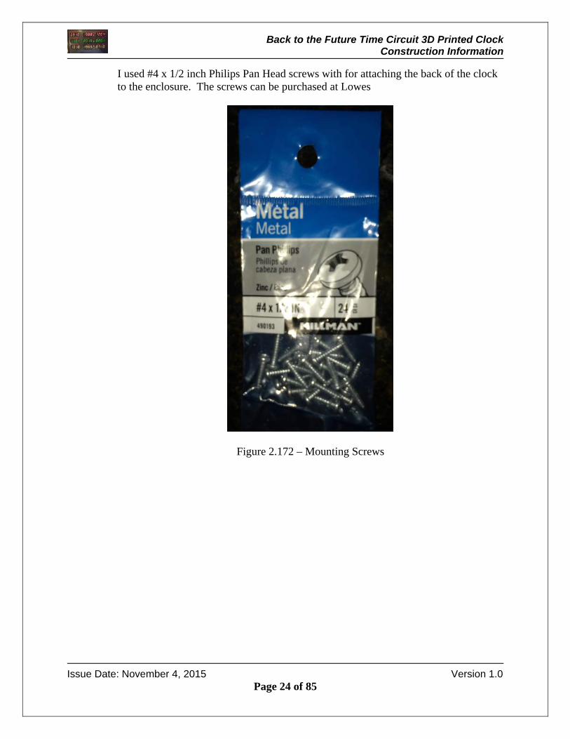
I used #4 x 1/2 inch Philips Pan Head screws with for attaching the back of the clock to the enclosure. The screws can be purchased at Lowes
Figure 2.172 – Mounting Screws

Back to the Future Time Circuit 3D Printed Clock Construction Information
Issue Date: November 4, 2015 Version 1.0
Page 25 of 85
3 Clock Decals / Design
The original time circuit utilized labels that have a black background with white text and a red background with white text. A P-Touch label was my first choice but the new P-Touch labelers only have labels with a white background with red text. Older P-Touch labelers support the desired label (red background and white text). I used water slide decals to recreate the labels. To do this, I created labels and printed them on laser white waterslide decal paper. The decal paper wire was purchased at Amazon.com http://www.amazon.com/Papilio-Laser-Clear-Waterslide-sheets/dp/B005DFLVOG.
Once the decals are printed, a decal is placed in the water and then the decal is placed on the time circuit clock. When all decals are affixed to the clock face, you will have the following:
Figure 3.1 – Time Circuit Front with Decals
Back to the Future Time Circuit 3D Printed Clock Construction Information
Issue Date: November 4, 2015 Version 1.0
Page 26 of 85
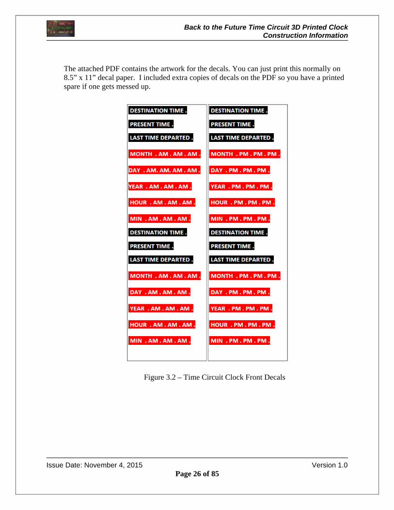
The attached PDF contains the artwork for the decals. You can just print this normally on 8.5” x 11” decal paper. I included extra copies of decals on the PDF so you have a printed spare if one gets messed up.
Figure 3.2 – Time Circuit Clock Front Decals
Back to the Future Time Circuit 3D Printed Clock Construction Information
Issue Date: November 4, 2015 Version 1.0
Page 27 of 85
4 3D Printing
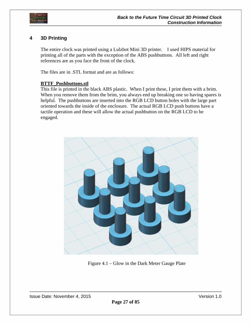
The entire clock was printed using a Lulzbot Mini 3D printer. I used HIPS material for printing all of the parts with the exception of the ABS pushbuttons. All left and right references are as you face the front of the clock. The files are in .STL format and are as follows: BTTF_Pushbuttons.stl This file is printed in the black ABS plastic. When I print these, I print them with a brim. When you remove them from the brim, you always end up breaking one so having spares is helpful. The pushbuttons are inserted into the RGB LCD button holes with the large part oriented towards the inside of the enclosure. The actual RGB LCD push buttons have a tactile operation and these will allow the actual pushbutton on the RGB LCD to be engaged.
Figure 4.1 – Glow in the Dark Meter Gauge Plate

Back to the Future Time Circuit 3D Printed Clock Construction Information
Issue Date: November 4, 2015 Version 1.0
Page 28 of 85
The picture below is shown with the pushbuttons placed in the top panel. The RGB LCD will be mounted so that the ABS pushbuttons press the actual RGB LCD pushbuttons.
Figure 4.2 – Pushbutton Location
Pushbuttons
Back to the Future Time Circuit 3D Printed Clock Construction Information
Issue Date: November 4, 2015 Version 1.0
Page 29 of 85
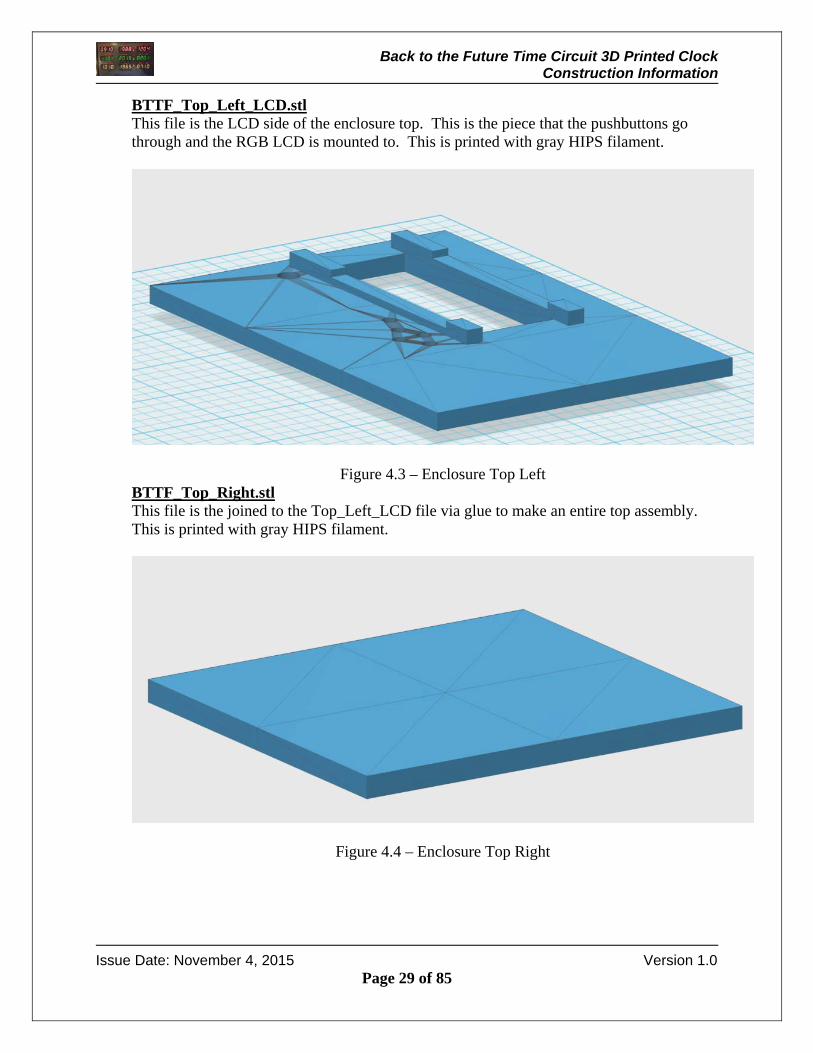
BTTF_Top_Left_LCD.stl This file is the LCD side of the enclosure top. This is the piece that the pushbuttons go through and the RGB LCD is mounted to. This is printed with gray HIPS filament.
Figure 4.3 – Enclosure Top Left BTTF_Top_Right.stl This file is the joined to the Top_Left_LCD file via glue to make an entire top assembly. This is printed with gray HIPS filament.
Figure 4.4 – Enclosure Top Right
Back to the Future Time Circuit 3D Printed Clock Construction Information
Issue Date: November 4, 2015 Version 1.0
Page 30 of 85
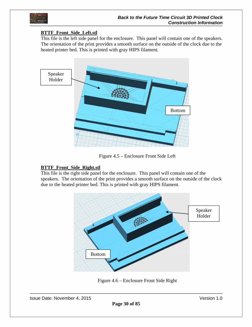
BTTF_Front_Side_Left.stl This file is the left side panel for the enclosure. This panel will contain one of the speakers. The orientation of the print provides a smooth surface on the outside of the clock due to the heated printer bed. This is printed with gray HIPS filament.
Figure 4.5 – Enclosure Front Side Left
BTTF_Front_Side_Right.stl This file is the right side panel for the enclosure. This panel will contain one of the speakers. The orientation of the print provides a smooth surface on the outside of the clock due to the heated printer bed. This is printed with gray HIPS filament.
Figure 4.6 – Enclosure Front Side Right
Bottom
Bottom
Speaker Holder
Speaker Holder

Back to the Future Time Circuit 3D Printed Clock Construction Information
Issue Date: November 4, 2015 Version 1.0
Page 31 of 85
BTTF_Speaker_Covers.stl This file contains the speaker covers. The covers slide into the channel on the speaker holders to prevent the speaker from falling out of the holder. These are printed with gray HIPS filament.
Figure 4.7 – Clock Speaker Covers

Back to the Future Time Circuit 3D Printed Clock Construction Information
Issue Date: November 4, 2015 Version 1.0
Page 32 of 85
BTTF_Front_LED_Left.stl This file is the left side of the front display. The orientation of the print provides a smooth surface on the outside of the clock due to the heated printer bed. This is printed with gray HIPS filament.
Figure 4.8 – Enclosure Front LED Left

Back to the Future Time Circuit 3D Printed Clock Construction Information
Issue Date: November 4, 2015 Version 1.0
Page 33 of 85
BTTF_Front_LED_Right.stl This file is the right side of the front display. The orientation of the print provides a smooth surface on the outside of the clock due to the heated printer bed. This is printed with gray HIPS filament. The two front panel pieces are joined with glue to create a solid front assembly.
Figure 4.9 – Enclosure Front LED Right

Back to the Future Time Circuit 3D Printed Clock Construction Information
Issue Date: November 4, 2015 Version 1.0
Page 34 of 85
BTTF_Bottom_Left.stl This file is the bottom left hand side of the enclosure. The orientation of the print provides a smooth surface on the outside of the clock due to the heated printer bed. This is printed with gray HIPS filament.
Figure 4.10 – Enclosure Bottom Left
Glue on this side
Arduino Mounting Holes

Back to the Future Time Circuit 3D Printed Clock Construction Information
Issue Date: November 4, 2015 Version 1.0
Page 35 of 85
BTTF_Bottom_Right.stl This file is the bottom left hand side of the enclosure. The orientation of the print provides a smooth surface on the outside of the clock due to the heated printer bed. This is printed with gray HIPS filament.
Figure 4.11 – Enclosure Bottom Right
Glue on this side
Back to the Future Time Circuit 3D Printed Clock Construction Information
Issue Date: November 4, 2015 Version 1.0
Page 36 of 85
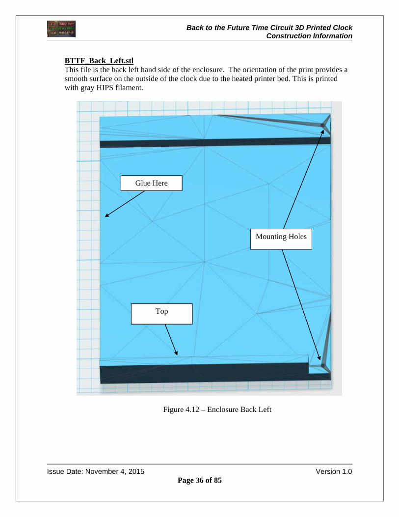
BTTF_Back_Left.stl This file is the back left hand side of the enclosure. The orientation of the print provides a smooth surface on the outside of the clock due to the heated printer bed. This is printed with gray HIPS filament.
Figure 4.12 – Enclosure Back Left
Mounting Holes
Top
Glue Here
Back to the Future Time Circuit 3D Printed Clock Construction Information
Issue Date: November 4, 2015 Version 1.0
Page 37 of 85
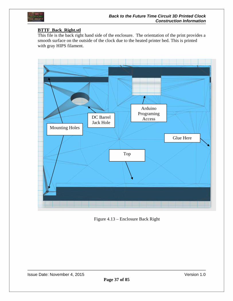
BTTF_Back_Right.stl This file is the back right hand side of the enclosure. The orientation of the print provides a smooth surface on the outside of the clock due to the heated printer bed. This is printed with gray HIPS filament.
Figure 4.13 – Enclosure Back Right
Mounting Holes
Top
Arduino Programing
AccessDC Barrel Jack Hole
Glue Here
Back to the Future Time Circuit 3D Printed Clock Construction Information
Issue Date: November 4, 2015 Version 1.0
Page 38 of 85
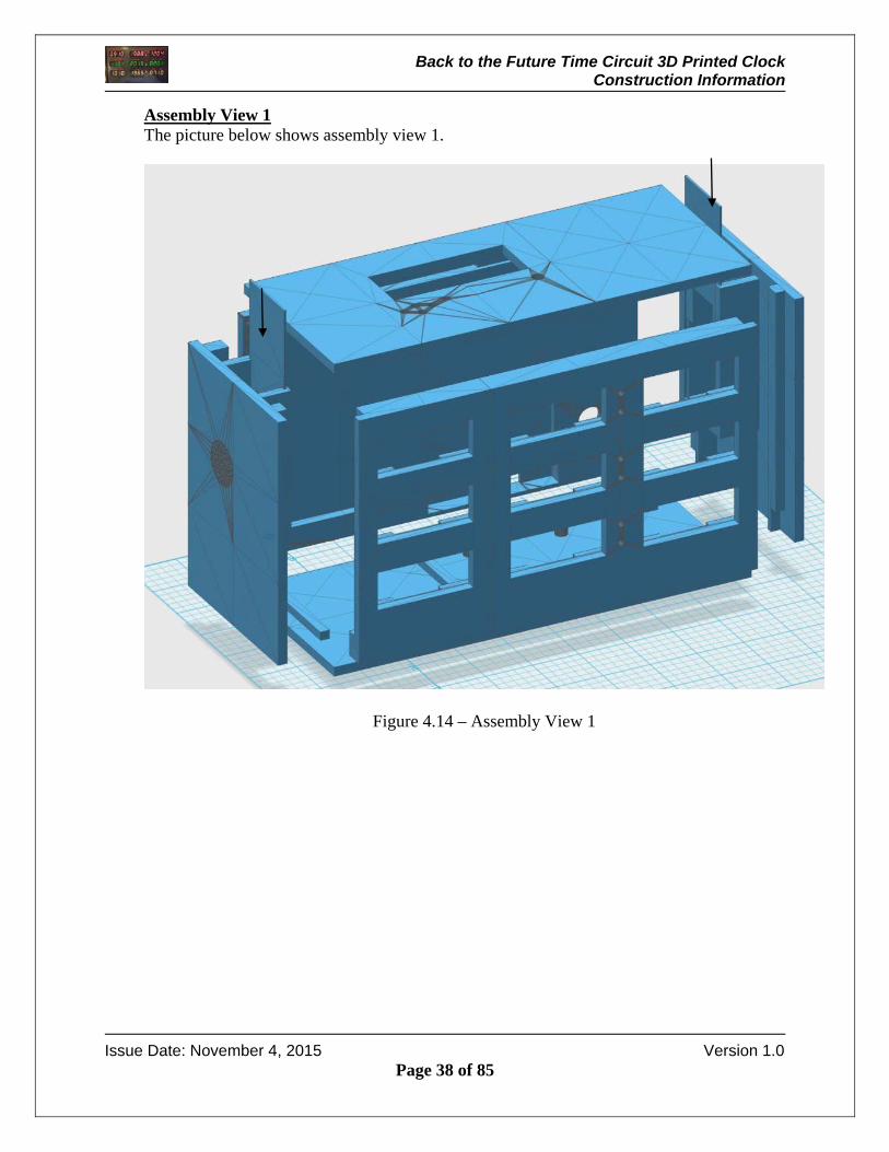
Assembly View 1 The picture below shows assembly view 1.
Figure 4.14 – Assembly View 1
Back to the Future Time Circuit 3D Printed Clock Construction Information
Issue Date: November 4, 2015 Version 1.0
Page 39 of 85
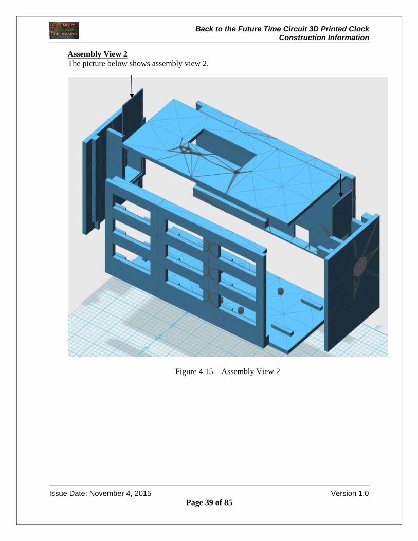
Assembly View 2 The picture below shows assembly view 2.
Figure 4.15 – Assembly View 2
Back to the Future Time Circuit 3D Printed Clock Construction Information
Issue Date: November 4, 2015 Version 1.0
Page 40 of 85
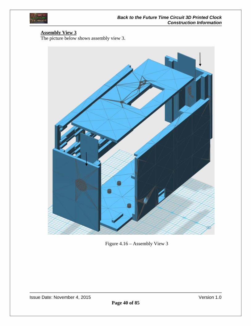
Assembly View 3 The picture below shows assembly view 3.
Figure 4.16 – Assembly View 3
Back to the Future Time Circuit 3D Printed Clock Construction Information
Issue Date: November 4, 2015 Version 1.0
Page 41 of 85
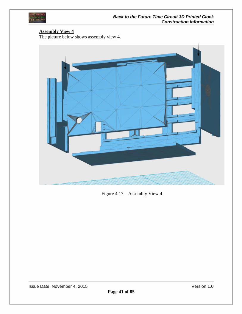
Assembly View 4 The picture below shows assembly view 4.
Figure 4.17 – Assembly View 4
Back to the Future Time Circuit 3D Printed Clock Construction Information
Issue Date: November 4, 2015 Version 1.0
Page 42 of 85
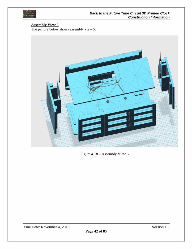
Assembly View 5 The picture below shows assembly view 5.
Figure 4.18 – Assembly View 5
Back to the Future Time Circuit 3D Printed Clock Construction Information
Issue Date: November 4, 2015 Version 1.0
Page 43 of 85
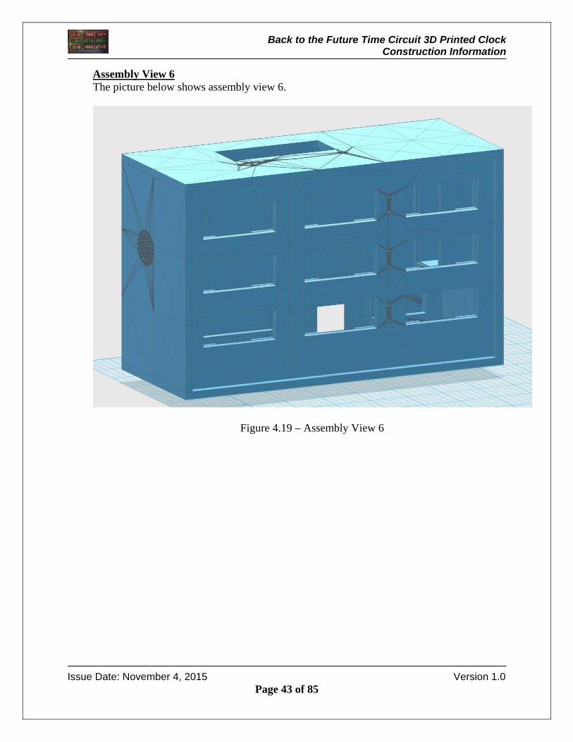
Assembly View 6 The picture below shows assembly view 6.
Figure 4.19 – Assembly View 6

Back to the Future Time Circuit 3D Printed Clock Construction Information
Issue Date: November 4, 2015 Version 1.0
Page 44 of 85
Assembly View 7 The picture below shows assembly view 7.
Figure 4.20 – Assembly View 7

Back to the Future Time Circuit 3D Printed Clock Construction Information
Issue Date: November 4, 2015 Version 1.0
Page 45 of 85
5 Construction
Once the 3D parts are printed and the components have been gathered, it is time to start the build process. The following steps outline the assembly process. 5.1 Glue the Top, Front and Bottom Halves
The enclosure pieces are glued using SCIGRIP Weld-On 3 cement. The cement is a high strength water thin acrylic cement that dries quickly. I used the SCIGRIP Weld-On 3 cement from Tapplastics.com http://www.tapplastics.com/product/repair_products/plastic_adhesives/weld_on_3_cement/131
Figure 5.11 – Acrylic Cement
The cement is applied with a Syringe Hypodermic Applicator as shown below. I used the syringe from Tapplastics.com (SY20-65) http://www.tapplastics.com/product/repair_products/plastic_adhesives/hypo_type_solvent_cement_applicator/409
Figure 5.12 – Cement Applicator Syringe
Back to the Future Time Circuit 3D Printed Clock Construction Information
Issue Date: November 4, 2015 Version 1.0
Page 46 of 85
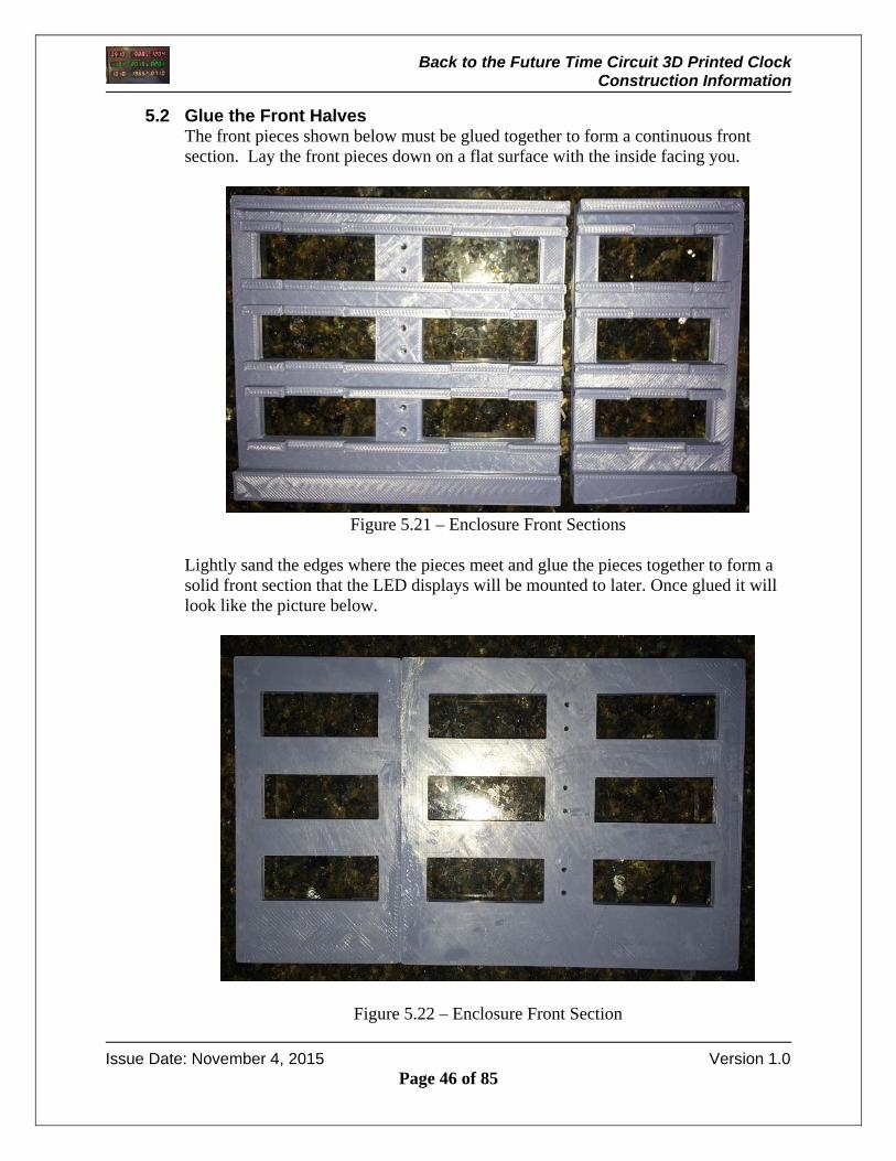
5.2 Glue the Front Halves The front pieces shown below must be glued together to form a continuous front section. Lay the front pieces down on a flat surface with the inside facing you.
Figure 5.21 – Enclosure Front Sections
Lightly sand the edges where the pieces meet and glue the pieces together to form a solid front section that the LED displays will be mounted to later. Once glued it will look like the picture below.
Figure 5.22 – Enclosure Front Section
Back to the Future Time Circuit 3D Printed Clock Construction Information
Issue Date: November 4, 2015 Version 1.0
Page 47 of 85
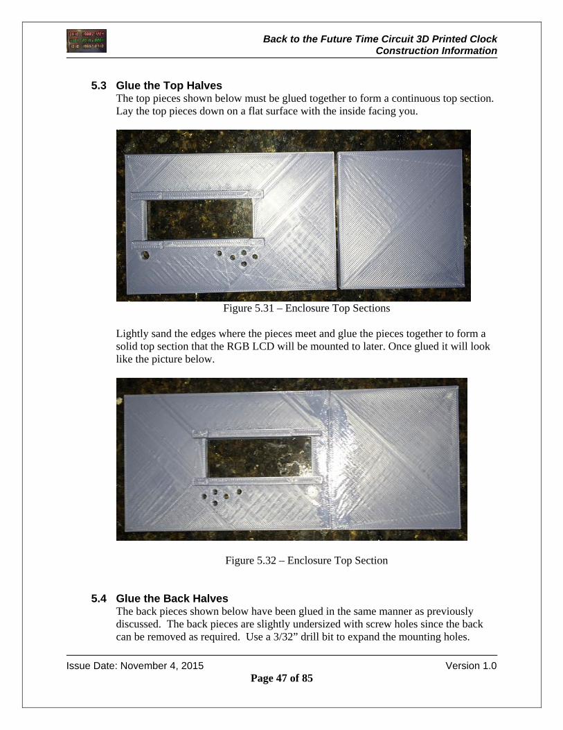
5.3 Glue the Top Halves
The top pieces shown below must be glued together to form a continuous top section. Lay the top pieces down on a flat surface with the inside facing you.
Figure 5.31 – Enclosure Top Sections
Lightly sand the edges where the pieces meet and glue the pieces together to form a solid top section that the RGB LCD will be mounted to later. Once glued it will look like the picture below.
Figure 5.32 – Enclosure Top Section
5.4 Glue the Back Halves The back pieces shown below have been glued in the same manner as previously discussed. The back pieces are slightly undersized with screw holes since the back can be removed as required. Use a 3/32” drill bit to expand the mounting holes.

Back to the Future Time Circuit 3D Printed Clock Construction Information
Issue Date: November 4, 2015 Version 1.0
Page 48 of 85
Figure 5.41 – Enclosure Back Inside
Lightly sand the edges where the pieces meet and glue the pieces together to form a solid back cover. Once glued it will look like the picture shown above.
Figure 5.42 – Enclosure Back Outside

Back to the Future Time Circuit 3D Printed Clock Construction Information
Issue Date: November 4, 2015 Version 1.0
Page 49 of 85
5.5 Glue the Bottom Halves The bottom pieces shown below have to be glued in the same manner as previously discussed.
Figure 5.51 – Bottom Enclosure Halves
Front
Back to the Future Time Circuit 3D Printed Clock Construction Information
Issue Date: November 4, 2015 Version 1.0
Page 50 of 85
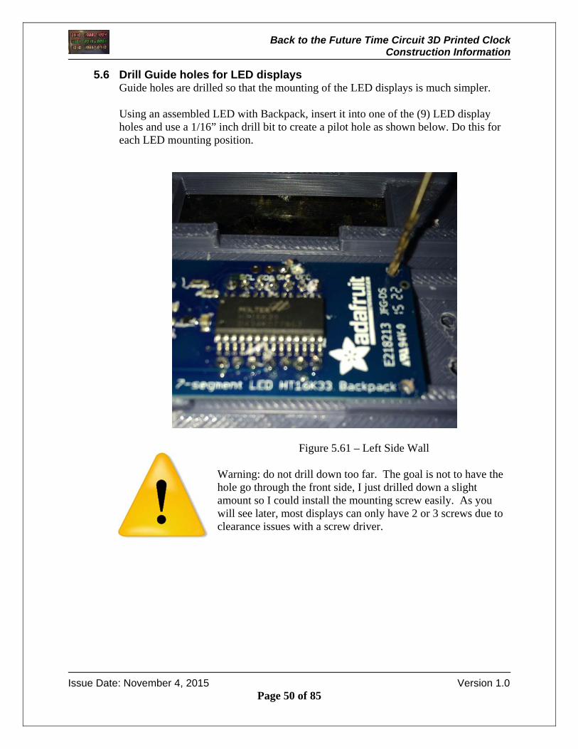
5.6 Drill Guide holes for LED displays Guide holes are drilled so that the mounting of the LED displays is much simpler. Using an assembled LED with Backpack, insert it into one of the (9) LED display holes and use a 1/16” inch drill bit to create a pilot hole as shown below. Do this for each LED mounting position.
Figure 5.61 – Left Side Wall
Warning: do not drill down too far. The goal is not to have the hole go through the front side, I just drilled down a slight amount so I could install the mounting screw easily. As you will see later, most displays can only have 2 or 3 screws due to clearance issues with a screw driver.
Back to the Future Time Circuit 3D Printed Clock Construction Information
Issue Date: November 4, 2015 Version 1.0
Page 51 of 85
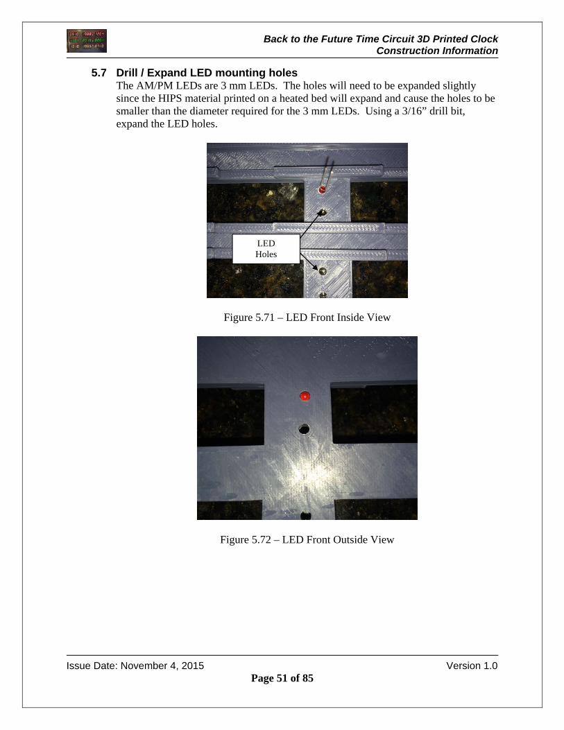
5.7 Drill / Expand LED mounting holes The AM/PM LEDs are 3 mm LEDs. The holes will need to be expanded slightly since the HIPS material printed on a heated bed will expand and cause the holes to be smaller than the diameter required for the 3 mm LEDs. Using a 3/16” drill bit, expand the LED holes.
Figure 5.71 – LED Front Inside View
Figure 5.72 – LED Front Outside View
LED Holes

Back to the Future Time Circuit 3D Printed Clock Construction Information
Issue Date: November 4, 2015 Version 1.0
Page 52 of 85
5.8 Drill Guide holes for RGB LCD display The RGB LCD display is shown laying on the mounting rails. Using a 1/16” drill bit drill a starter hole as you did for the LED displays.
Figure 5.81 – LED Front Inside View
Drill Here
Drill Here

Back to the Future Time Circuit 3D Printed Clock Construction Information
Issue Date: November 4, 2015 Version 1.0
Page 53 of 85
5.9 Drill / Expand RGB LCD Pushbutton / Contrast holes The pushbutton holes will need to be expanded slightly since the HIPS material printed on a heated bed will expand and cause the holes smaller than required. Using a 3/16” drill bit, expand the pushbutton holes. Use a 5/16 drill bit to expand the contrast adjustment hole.
Figure 5.91 – LED Front Inside View
Figure 5.92 – LED Front Outside View
Contrast Adjustment
Access Pushbutton
Holes
Back to the Future Time Circuit 3D Printed Clock Construction Information
Issue Date: November 4, 2015 Version 1.0
Page 54 of 85
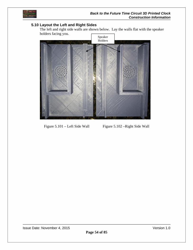
5.10 Layout the Left and Right Sides The left and right side walls are shown below. Lay the walls flat with the speaker holders facing you.
Figure 5.101 – Left Side Wall Figure 5.102 –Right Side Wall
Speaker Holders
Back to the Future Time Circuit 3D Printed Clock Construction Information
Issue Date: November 4, 2015 Version 1.0
Page 55 of 85
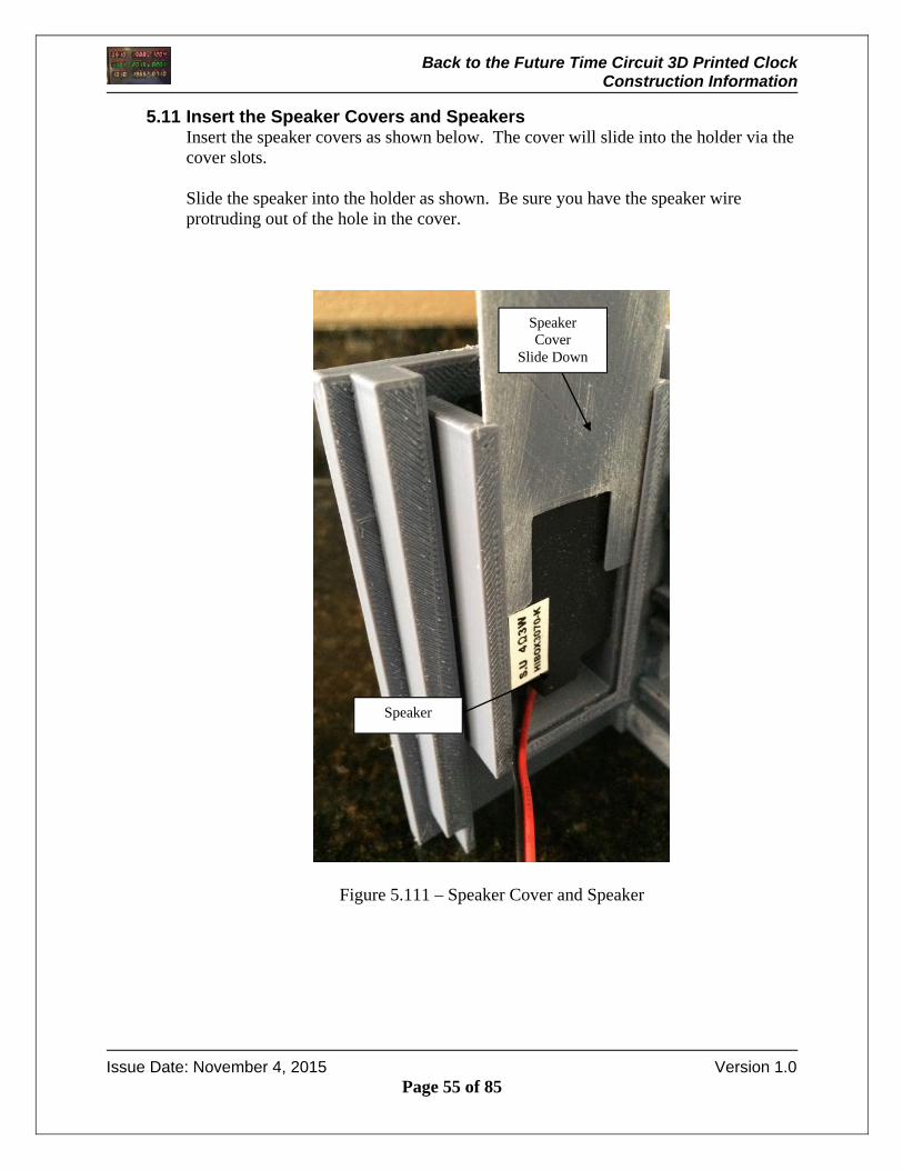
5.11 Insert the Speaker Covers and Speakers Insert the speaker covers as shown below. The cover will slide into the holder via the cover slots. Slide the speaker into the holder as shown. Be sure you have the speaker wire protruding out of the hole in the cover.
Figure 5.111 – Speaker Cover and Speaker
Speaker
Speaker Cover
Slide Down

Back to the Future Time Circuit 3D Printed Clock Construction Information
Issue Date: November 4, 2015 Version 1.0
Page 56 of 85
5.12 Glue the Enclosure The enclosure is glued using SCIGRIP Weld-On 3 cement. The cement is a high strength water thin acrylic cement that dries quickly. I used the SCIGRIP Weld-On 3 cement from Tapplastics.com http://www.tapplastics.com/product/repair_products/plastic_adhesives/weld_on_3_cement/131
Figure 5.121 – Acrylic Cement
The cement is applied with a Syringe Hypodermic Applicator as shown below. I used the syringe from Tapplastics.com (SY20-65) http://www.tapplastics.com/product/repair_products/plastic_adhesives/hypo_type_solvent_cement_applicator/409
Figure 5.122 – Cement Applicator Syringe The easy way to load the syringe is to remove the needle and pull up on the syringe shaft that is located in the polypropylene chamber with the needle end submersed in the cement canister. Once the syringe has cement in it, twist on the needle. Start applying glue to all of the seams of the enclosure as shown in the following assembly steps. After 15 minutes the cement will have cured enough to remove the tape. Experiment with the cement on some scrap pieces of printed material. You will soon understand how the cement flows and the cure time involved.
Back to the Future Time Circuit 3D Printed Clock Construction Information
Issue Date: November 4, 2015 Version 1.0
Page 57 of 85
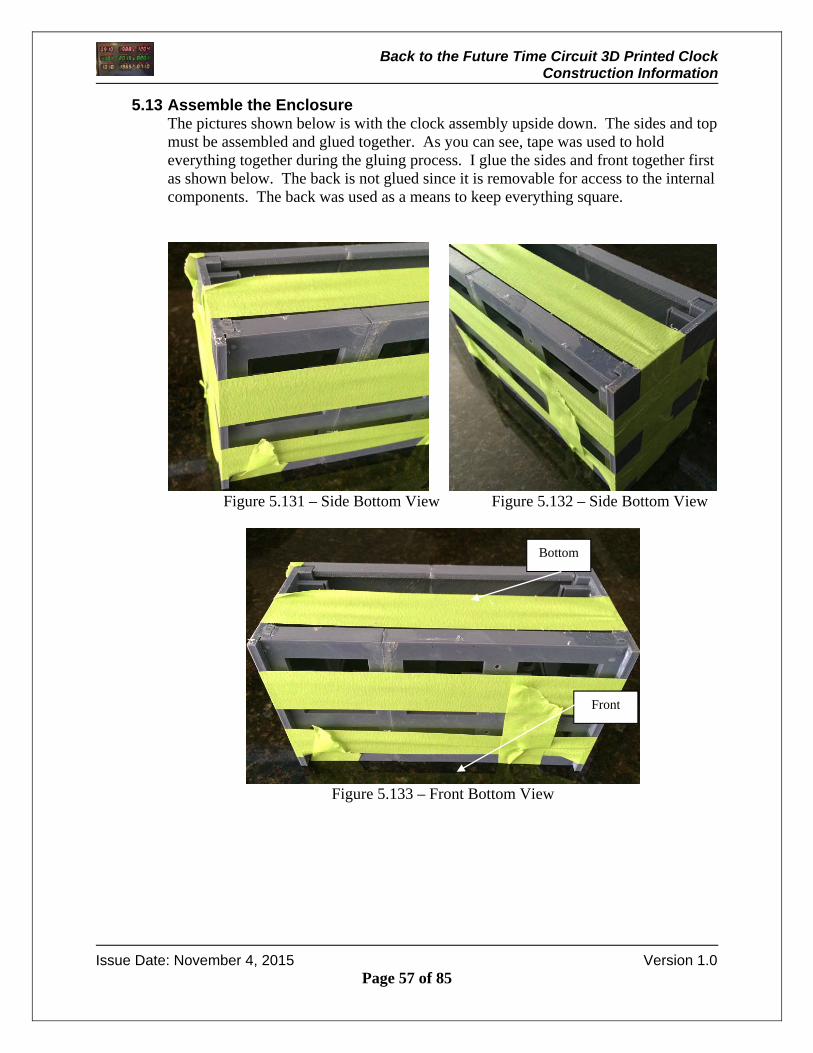
5.13 Assemble the Enclosure The pictures shown below is with the clock assembly upside down. The sides and top must be assembled and glued together. As you can see, tape was used to hold everything together during the gluing process. I glue the sides and front together first as shown below. The back is not glued since it is removable for access to the internal components. The back was used as a means to keep everything square.
Figure 5.131 – Side Bottom View Figure 5.132 – Side Bottom View
Figure 5.133 – Front Bottom View
Bottom
Front
Back to the Future Time Circuit 3D Printed Clock Construction Information
Issue Date: November 4, 2015 Version 1.0
Page 58 of 85
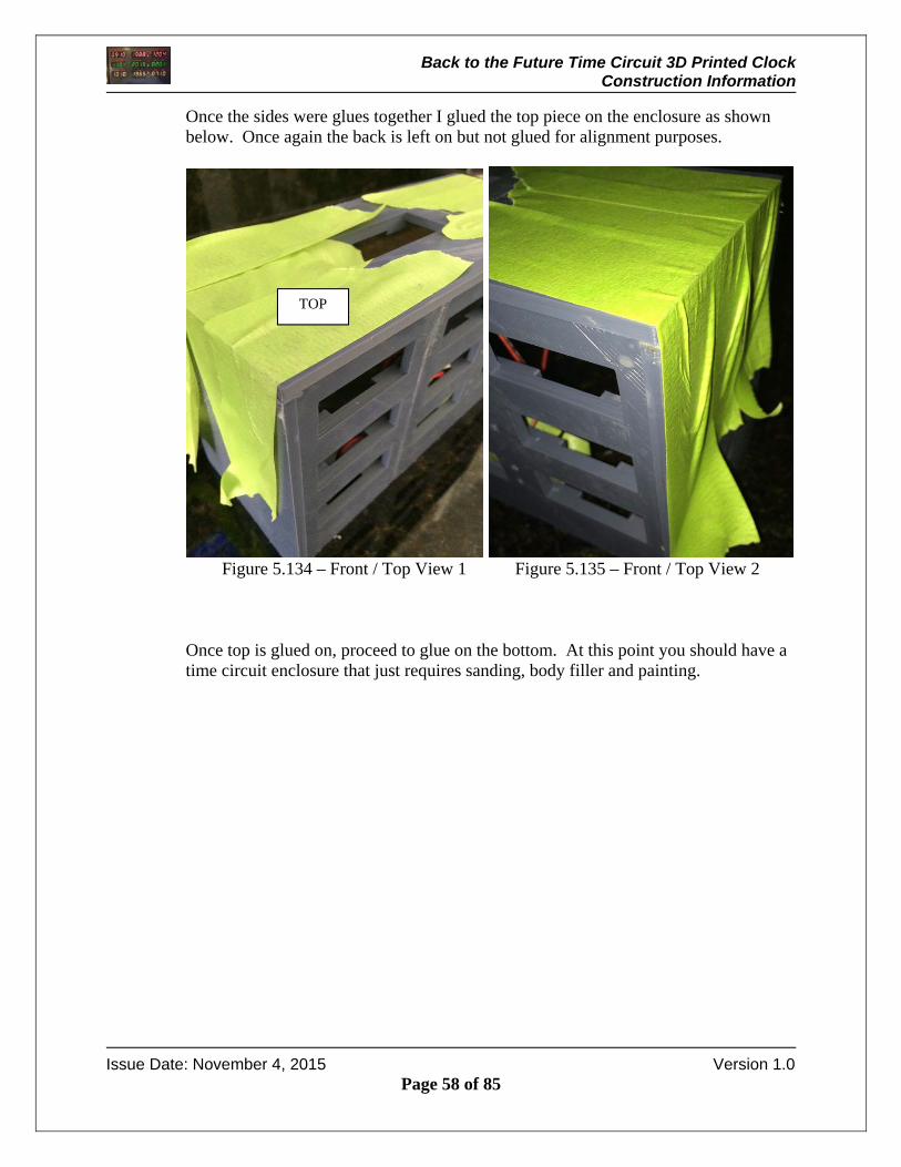
Once the sides were glues together I glued the top piece on the enclosure as shown below. Once again the back is left on but not glued for alignment purposes.
Figure 5.134 – Front / Top View 1 Figure 5.135 – Front / Top View 2
Once top is glued on, proceed to glue on the bottom. At this point you should have a time circuit enclosure that just requires sanding, body filler and painting.
TOP
Back to the Future Time Circuit 3D Printed Clock Construction Information
Issue Date: November 4, 2015 Version 1.0
Page 59 of 85
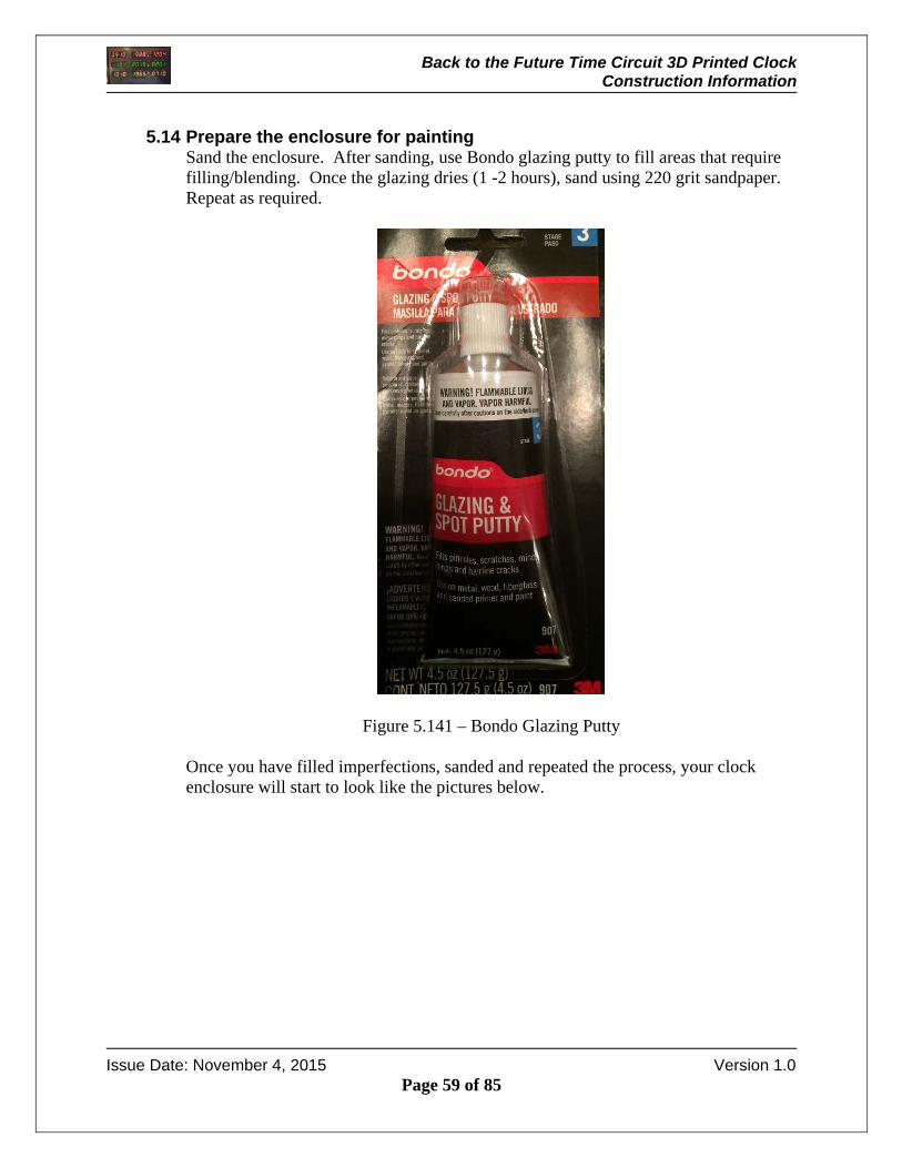
5.14 Prepare the enclosure for painting
Sand the enclosure. After sanding, use Bondo glazing putty to fill areas that require filling/blending. Once the glazing dries (1 -2 hours), sand using 220 grit sandpaper. Repeat as required.
Figure 5.141 – Bondo Glazing Putty
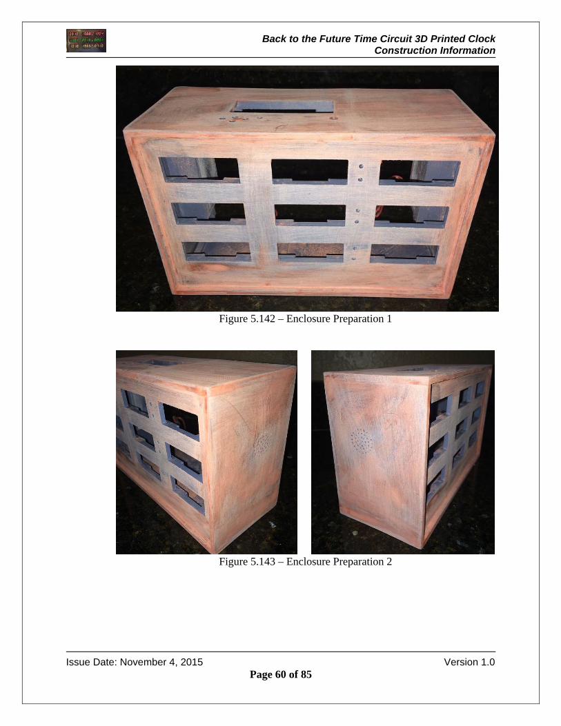
Once you have filled imperfections, sanded and repeated the process, your clock enclosure will start to look like the pictures below.
Back to the Future Time Circuit 3D Printed Clock Construction Information
Issue Date: November 4, 2015 Version 1.0
Page 60 of 85
Figure 5.142 – Enclosure Preparation 1
Figure 5.143 – Enclosure Preparation 2
Back to the Future Time Circuit 3D Printed Clock Construction Information
Issue Date: November 4, 2015 Version 1.0
Page 61 of 85
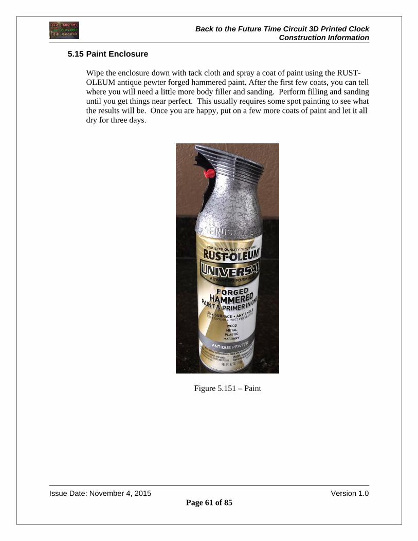
5.15 Paint Enclosure Wipe the enclosure down with tack cloth and spray a coat of paint using the RUST-OLEUM antique pewter forged hammered paint. After the first few coats, you can tell where you will need a little more body filler and sanding. Perform filling and sanding until you get things near perfect. This usually requires some spot painting to see what the results will be. Once you are happy, put on a few more coats of paint and let it all dry for three days.
Figure 5.151 – Paint
Back to the Future Time Circuit 3D Printed Clock Construction Information
Issue Date: November 4, 2015 Version 1.0
Page 62 of 85
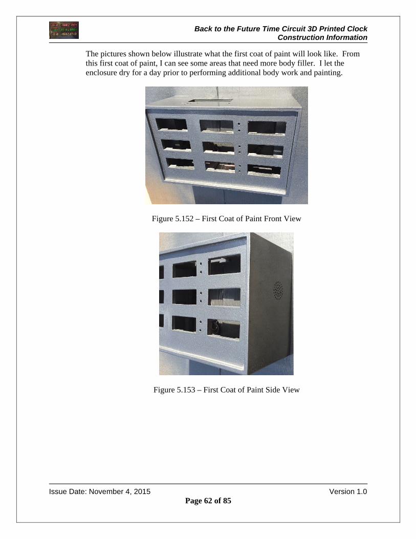
The pictures shown below illustrate what the first coat of paint will look like. From this first coat of paint, I can see some areas that need more body filler. I let the enclosure dry for a day prior to performing additional body work and painting.
Figure 5.152 – First Coat of Paint Front View
Figure 5.153 – First Coat of Paint Side View

Back to the Future Time Circuit 3D Printed Clock Construction Information
Issue Date: November 4, 2015 Version 1.0
Page 63 of 85
5.16 Assemble Music Maker
Assemble the music maker per the instructions listed at Adafruit.com. Be sure to solder the +12 dB jumper shown below to provide the clock with an acceptable volume level.
Figure 5.161 – Pushbutton LED Holder Mounting
+12 DB Jumper
Back to the Future Time Circuit 3D Printed Clock Construction Information
Issue Date: November 4, 2015 Version 1.0
Page 64 of 85
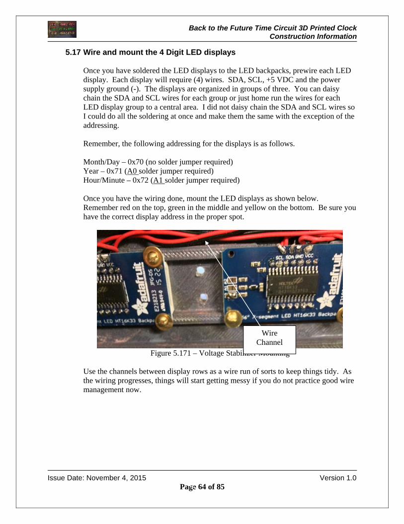
5.17 Wire and mount the 4 Digit LED displays
Once you have soldered the LED displays to the LED backpacks, prewire each LED display. Each display will require (4) wires. SDA, SCL, +5 VDC and the power supply ground (-). The displays are organized in groups of three. You can daisy chain the SDA and SCL wires for each group or just home run the wires for each LED display group to a central area. I did not daisy chain the SDA and SCL wires so I could do all the soldering at once and make them the same with the exception of the addressing. Remember, the following addressing for the displays is as follows. Month/Day – 0x70 (no solder jumper required) Year – 0x71 (A0 solder jumper required) Hour/Minute – 0x72 (A1 solder jumper required) Once you have the wiring done, mount the LED displays as shown below. Remember red on the top, green in the middle and yellow on the bottom. Be sure you have the correct display address in the proper spot.
Figure 5.171 – Voltage Stabilizer Mounting
Use the channels between display rows as a wire run of sorts to keep things tidy. As the wiring progresses, things will start getting messy if you do not practice good wire management now.
Wire Channel
Back to the Future Time Circuit 3D Printed Clock Construction Information
Issue Date: November 4, 2015 Version 1.0
Page 65 of 85
5.18 Wire and Mount AM/PM LEDs
Wire each of the six LEDs to a wire pair with 330 ohm resistor. I soldered the resistor to the LED short lead (+) and then a red wire to the resistor. I soldered a black wire to the long lead (-) and I covered the solder connections with heat shrink. I connected each LED assembly to a temporary power source to ensure they were operating properly prior to using epoxy to install. Now that you have the LED assemblies, Stick the LED in its associated LED hole and bend the leads over. Once you installed the LEDs in the holes, mix some epoxy and pour a small amount over each LED on the inside of the enclosure. Remember red on the top, green in the middle and yellow on the bottom.

Back to the Future Time Circuit 3D Printed Clock Construction Information
Issue Date: November 4, 2015 Version 1.0
Page 66 of 85
5.19 Mount the Voltage Stabilizer
Pre-wire the incoming and outgoing power to the voltage stabilizer. Just wire a few long wire pairs to the terminals on the voltage stabilizer. We will connect these later. Once it is pre-wired, mount the voltage stabilizer to the base using (2) #2 screws. Due to clearance issues you will only be able to get two mounting screws in the voltage stabilizer.
Figure 5.191 – Voltage Stabilizer Mounting
Mounting Screws
9 VDC Power
Incoming
5 VDC Power
Outgoing

Back to the Future Time Circuit 3D Printed Clock Construction Information
Issue Date: November 4, 2015 Version 1.0
Page 67 of 85
5.20 Mount the Arduino Uno
Mount the Arduino Uno to the base using (2) #4 screws. Due to clearance issues you will only be able to get two mounting screws in the Arduino Uno.
Figure 5.201 – Arduino Header Connections
Mounting Screws
Back to the Future Time Circuit 3D Printed Clock Construction Information
Issue Date: November 4, 2015 Version 1.0
Page 68 of 85
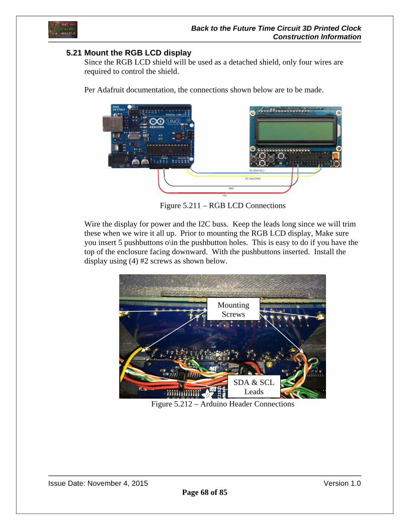
5.21 Mount the RGB LCD display Since the RGB LCD shield will be used as a detached shield, only four wires are required to control the shield. Per Adafruit documentation, the connections shown below are to be made.
Figure 5.211 – RGB LCD Connections
Wire the display for power and the I2C buss. Keep the leads long since we will trim these when we wire it all up. Prior to mounting the RGB LCD display, Make sure you insert 5 pushbuttons o\in the pushbutton holes. This is easy to do if you have the top of the enclosure facing downward. With the pushbuttons inserted. Install the display using (4) #2 screws as shown below.
Figure 5.212 – Arduino Header Connections
Mounting Screws
SDA & SCL Leads
Back to the Future Time Circuit 3D Printed Clock Construction Information
Issue Date: November 4, 2015 Version 1.0
Page 69 of 85
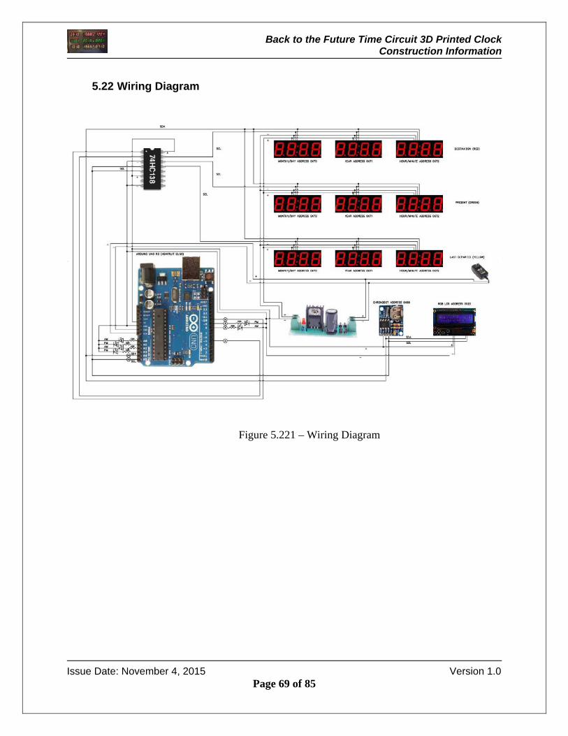
5.22 Wiring Diagram
Figure 5.221 – Wiring Diagram
Back to the Future Time Circuit 3D Printed Clock Construction Information
Issue Date: November 4, 2015 Version 1.0
Page 70 of 85
5.23 Wire the Perma-Proto Board
The 3 to 8 line decoder chip and the Chronodot are wired and soldered to the Perma-Proto breadboard. I used a 16 pin IC socket and snapped the decoder chip into the socket once the wiring was completed. Use the wiring diagram attached to determine the connections that are to be made. The IC chip is controlled via two select pins controlled by the Arduino. The select pins are used to determine the routing for the SCL signal to the three different LED display groups. The Perma-Proto board sits on the bottom of the enclosure on the mounting rail next to the Arduino. You can attach this if you wish. I left mine loose so I could access it as required for debug and test.
5.24 Wire the Screwshield
Wire the screw shield. Use the electrical schematic for wiring information. The Screwshield will be wired to the following: (VIN +) 9 VDC positive from the wall adapter (VIN -) 9 VDC negative from the wall adapter (Pin 5) 3 to 8 line decoder SCL select line 1 (Pin 10) 3 to 8 line decoder SCL select line 2 (Pin 8) Green AM LED (Pin 9) Green PM LED (Pin A0) Red AM LED (Pin A1) Red PM LED (Pin A2) Yellow AM LED (Pin A3) Yellow PM LED (Pin A4) SDA to RGB LCD, Chronodot, and All LED displays (Pin A5) SCL to RGB LCD, Chronodot, and All LED displays (Pin 5V) 5 VDC power connection to RGB LCD, Chronodot, 3 to 8 line decoder (Pin GND) Ground connection to to RGB LCD, Chronodot, 3 to 8 line decoder, voltage stabilizer ground (tie grounds together), AM/PM LEDs.
5.25 Install Arduino and Screwshield
Once you have the Screwshield wired, install the Arduino to the base using two #4 screws if not already mounted. Once the Arduino is mounted, put the Screwshield on the Arduino. Take your time and be sure the pins are lined up to the Arduino sockets.

Back to the Future Time Circuit 3D Printed Clock Construction Information
Issue Date: November 4, 2015 Version 1.0
Page 71 of 85
5.26 Install Music Maker on Screwshield
With the Arduino installed on the base and the Screwshield plugged into the Arduino, the final step of the circuit board sandwich is to place the music maker on top of the Screwshield via the .1 “ female sockets on the Screwshield and the male pins on the music maker shield. Before attaching the music maker shield, it is a good idea to connect the speakers to the Music Maker. Once the speaker terminals are connected, insert the Music Maker onto the Screw Shield.
Figure 5.261 – Screwshield
Figure 5.262 – Music Maker Shield
Plug Music Maker in the Screw Shield
sockets
Speaker Connections
SD Audio File Storage

Back to the Future Time Circuit 3D Printed Clock Construction Information
Issue Date: November 4, 2015 Version 1.0
Page 72 of 85
5.27 Mount /Wire DC Barrel Connector
Insert the DC barrel connector through the hole on the back of the enclosure panel. Install the locking nut and wire as shown below. One set of wires is connected to the input side of the voltage stabilizer and the other set of wires is connected to VIN on the Arduino.
Figure 5.271 – RGB LCD Connections
Back to the Future Time Circuit 3D Printed Clock Construction Information
Issue Date: November 4, 2015 Version 1.0
Page 73 of 85
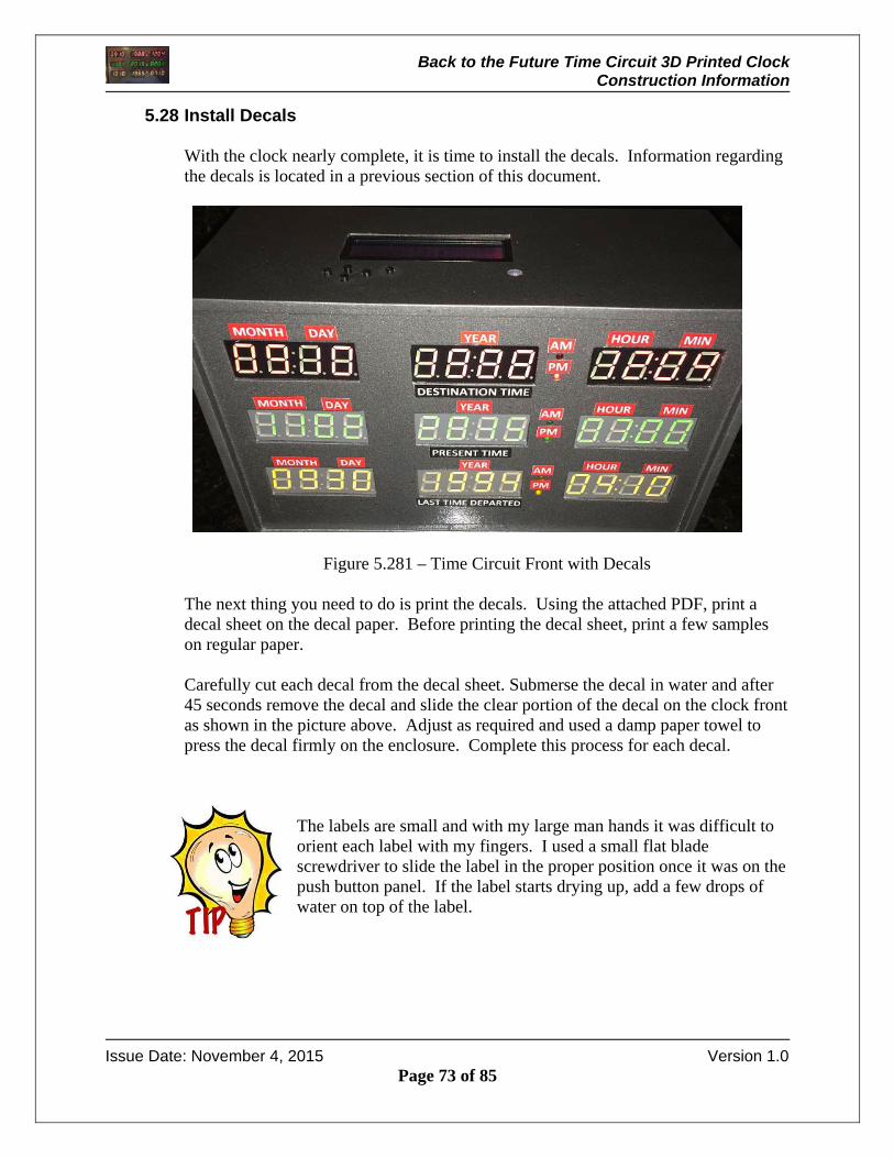
5.28 Install Decals With the clock nearly complete, it is time to install the decals. Information regarding the decals is located in a previous section of this document.
Figure 5.281 – Time Circuit Front with Decals The next thing you need to do is print the decals. Using the attached PDF, print a decal sheet on the decal paper. Before printing the decal sheet, print a few samples on regular paper. Carefully cut each decal from the decal sheet. Submerse the decal in water and after 45 seconds remove the decal and slide the clear portion of the decal on the clock front as shown in the picture above. Adjust as required and used a damp paper towel to press the decal firmly on the enclosure. Complete this process for each decal.
The labels are small and with my large man hands it was difficult to orient each label with my fingers. I used a small flat blade screwdriver to slide the label in the proper position once it was on the push button panel. If the label starts drying up, add a few drops of water on top of the label.
Back to the Future Time Circuit 3D Printed Clock Construction Information
Issue Date: November 4, 2015 Version 1.0
Page 74 of 85
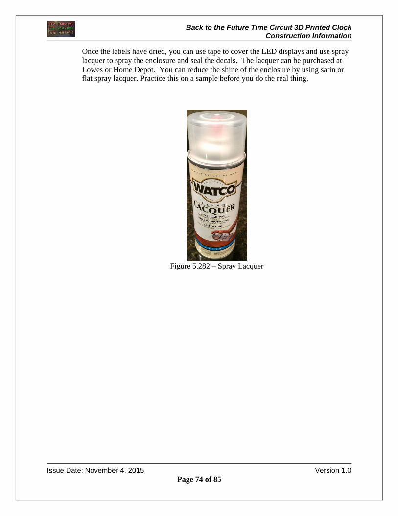
Once the labels have dried, you can use tape to cover the LED displays and use spray lacquer to spray the enclosure and seal the decals. The lacquer can be purchased at Lowes or Home Depot. You can reduce the shine of the enclosure by using satin or flat spray lacquer. Practice this on a sample before you do the real thing.
Figure 5.282 – Spray Lacquer

Back to the Future Time Circuit 3D Printed Clock Construction Information
Issue Date: November 4, 2015 Version 1.0
Page 75 of 85
5.29 Attach Base / Bumpers
Bumpers should be installed to prevent the clock from scratching furniture. The picture below shows the bumper installation.
Figure 5.291 – Mounting Base Plate / Bumpers
Bumpers
Back to the Future Time Circuit 3D Printed Clock Construction Information
Issue Date: November 4, 2015 Version 1.0
Page 76 of 85
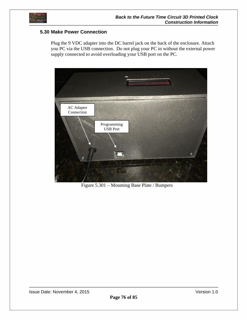
5.30 Make Power Connection
Plug the 9 VDC adapter into the DC barrel jack on the back of the enclosure. Attach you PC via the USB connection. Do not plug your PC in without the external power supply connected to avoid overloading your USB port on the PC.
Figure 5.301 – Mounting Base Plate / Bumpers
Programming USB Port
AC Adapter Connection

Back to the Future Time Circuit 3D Printed Clock Construction Information
Issue Date: November 4, 2015 Version 1.0
Page 77 of 85
6 RGB LCD Operation
An RGB LCD with keypad is located on the top of the enclosure. The RGB LCD shown below is used to change the hours and minutes without connecting a PC to the Arduino. This is a useful for adjusting for daylight savings time. Changing the time from the keypad will write the time to the RTC unit so that the change is retained through a power cycle.
Figure 6.1 – RGB LCD Kepad Display
The display is a two line device. The top line always shows the time in 24 hour format. The bottom line normally shows the date. When an increment or decrement pushbutton is pressed, the bottom line will display the function that is active.
Backlight On/Off
Minute Decrement
Minute Increment
Hour Increment
Contrast Adjustment
Hour Decrement

Back to the Future Time Circuit 3D Printed Clock Construction Information
Issue Date: November 4, 2015 Version 1.0
Page 78 of 85
Hour Increment Pressing the Hour Increment pushbutton will increase the hour. Pressing and holding the pushbutton will increment the hour once per second. When the pushbutton is pressed, the display will appear a follows:
Figure 6.2 – Increment Hour
Hour Decrement Pressing the Hour Decrement pushbutton will decrease the hour. Pressing and holding the pushbutton will decrement the hour once per second. When the pushbutton is pressed, the display will appear a follows:
Figure 6.3 – Decrement Hour

Back to the Future Time Circuit 3D Printed Clock Construction Information
Issue Date: November 4, 2015 Version 1.0
Page 79 of 85
Minute Increment Pressing the Minute Increment pushbutton will increase the minute. Pressing and holding the pushbutton will increment the minutes twice per second. When the pushbutton is pressed, the display will appear a follows:
Figure 6.4 – Increment Minutes
Minute Decrement Pressing the Minute Decrement pushbutton will decrease the minute. Pressing and holding the pushbutton will decrement the minutes twice per second. When the pushbutton is pressed, the display will appear a follows:
Figure 6.5 – Decrement Minutes

Back to the Future Time Circuit 3D Printed Clock Construction Information
Issue Date: November 4, 2015 Version 1.0
Page 80 of 85
Backlight On/Off Pressing the backlight pushbutton will turn off the LCD backlight. Pressing the pushbutton again will turn it on. The picture below shows the backlight turned off.
Figure 6.6 – Backlight Off
Contrast Adjustment To adjust the contrast of the RGB LCD display, place a small screw driver in the contrast access hole shown below. Pressing the backlight pushbutton will turn off the LCD backlight. Pressing the pushbutton again will turn it on. The picture below shows the backlight turned off.
Figure 6.7 – Contrast Adjustment
Back to the Future Time Circuit 3D Printed Clock Construction Information
Issue Date: November 4, 2015 Version 1.0
Page 81 of 85
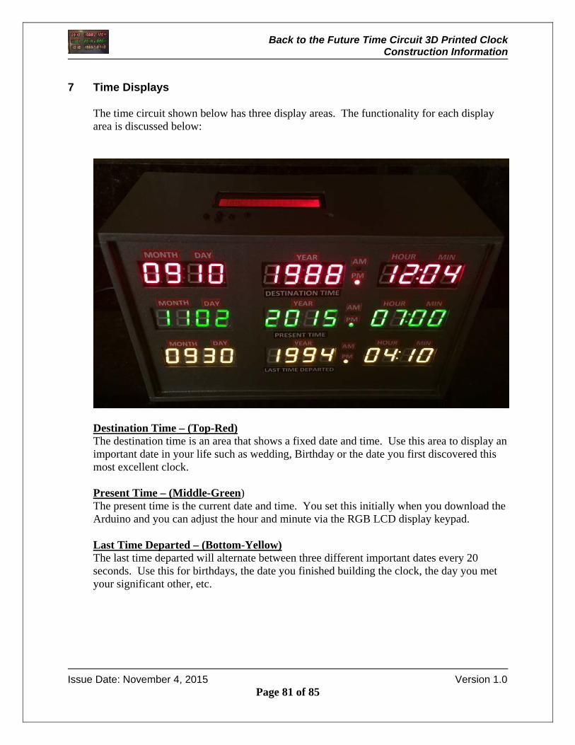
7 Time Displays
The time circuit shown below has three display areas. The functionality for each display area is discussed below:
Destination Time – (Top-Red) The destination time is an area that shows a fixed date and time. Use this area to display an important date in your life such as wedding, Birthday or the date you first discovered this most excellent clock. Present Time – (Middle-Green) The present time is the current date and time. You set this initially when you download the Arduino and you can adjust the hour and minute via the RGB LCD display keypad. Last Time Departed – (Bottom-Yellow) The last time departed will alternate between three different important dates every 20 seconds. Use this for birthdays, the date you finished building the clock, the day you met your significant other, etc.
Back to the Future Time Circuit 3D Printed Clock Construction Information
Issue Date: November 4, 2015 Version 1.0
Page 82 of 85
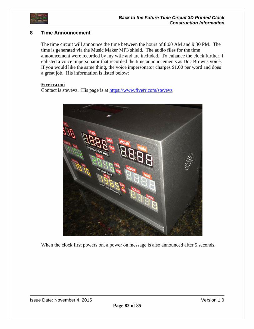
8 Time Announcement
The time circuit will announce the time between the hours of 8:00 AM and 9:30 PM. The time is generated via the Music Maker MP3 shield. The audio files for the time announcement were recorded by my wife and are included. To enhance the clock further, I enlisted a voice impersonator that recorded the time announcements as Doc Browns voice. If you would like the same thing, the voice impersonator charges $1.00 per word and does a great job. His information is listed below: Fiverr.com Contact is stevevz. His page is at https://www.fiverr.com/stevevz
When the clock first powers on, a power on message is also announced after 5 seconds.

Back to the Future Time Circuit 3D Printed Clock Construction Information
Issue Date: November 4, 2015 Version 1.0
Page 83 of 85
9 Power up Sequence
When power is first applied to the clock, the LED displays for the clock will fill in with the numbers as shown below.
A few seconds after the numbers appear, a power on message can be heard. At this point each display will begin updating. The update occurs based on the actual real time clock seconds value so it may take 30 seconds before all the displays have been updated initially.

Back to the Future Time Circuit 3D Printed Clock Construction Information
Issue Date: November 4, 2015 Version 1.0
Page 84 of 85
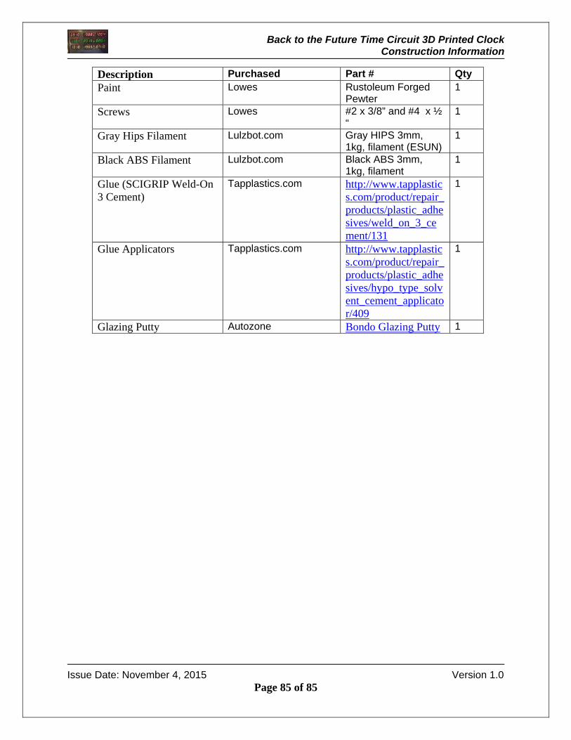
10 Parts Listing
The parts listed below were used to make the clock.
Description Purchased Part # Qty Arduino Uno R3 Adafruit.com Product ID: 50 1 Adafruit "Music Maker" MP3 Shield for Arduino w/3W Stereo Amp - v1.0
Adafruit.com Product ID: 1788 1
ChronoDot Real Time Clock
Adafruit.com Product ID: 255 1
Stereo Enclosed Speaker Set - 3W 4 Ohm
Adafruit.com Product ID: 1669 1
SD/MicroSD Memory Card (4 GB SDHC)
Adafruit.com Product ID: 102 1
Perma-Proto Half Sized Breadboard
Adafruit.com Product ID: 1609 1
Blinggasm Waterslide Decal Paper 10 Sheets Pack, Clear or White, Inkjet or Laser Printer Choose From Menu (WHITE FOR LASER PRINTER)
Amazon.com http://www.amazon.com/gp/product/B00ZLVF670?psc=1&redirect=true&ref_=oh_aui_search_detailpage
1
OMNIHIL AC/DC 9V 2A High Quality Power Adapter
Amazon.com http://www.amazon.com/gp/product/B00CAC399U?psc=1&redirect=true&ref_=oh_aui_detailpage_o00_s00
1
SMAKN® L7805 LM7805 3-Terminal Voltage Stabilizer 5V Voltage Stabilizer Power Module
Amazon.com http://www.amazon.com/gp/product/B00RKY0NP6?psc=1&redirect=true&ref_=oh_aui_detailpage_o01_s00
1
Arduino Proto Screw Shield
Amazon.com http://www.amazon.com/gp/product/B00HBVVKPA?psc=1&redirect=true&ref_=oh_aui_search_detailpage
1
Back to the Future Time Circuit 3D Printed Clock Construction Information
Issue Date: November 4, 2015 Version 1.0
Page 85 of 85
Description Purchased Part # Qty Paint Lowes Rustoleum Forged
Pewter 1
Screws Lowes #2 x 3/8” and #4 x ½ “
1
Gray Hips Filament Lulzbot.com Gray HIPS 3mm, 1kg, filament (ESUN)
1
Black ABS Filament Lulzbot.com Black ABS 3mm, 1kg, filament
1
Glue (SCIGRIP Weld-On 3 Cement)
Tapplastics.com http://www.tapplastics.com/product/repair_products/plastic_adhesives/weld_on_3_cement/131
1
Glue Applicators Tapplastics.com http://www.tapplastics.com/product/repair_products/plastic_adhesives/hypo_type_solvent_cement_applicator/409
1
Glazing Putty Autozone Bondo Glazing Putty 1