back-up power systems based on fuel cell technology for signalling
TRANSCRIPT

Challenge A: A more and more energy efficient railway
1
Back-up power systems based on fuel cell technologyfor signalling equipment electrical supply
Leone M.(*), Stellin M.(*)
Cantamerli G.(**)
(*) Rete Ferroviaria Italiana (RFI), Rome, Italy - (** )Omicron Industriale Srl, Rome, Italy
Abstract
As known, signalling equipments require absolutely no – break electrical power supply because oftheir severe impact on safety and availability of railway service.
For this reason the power supply systems for signalling include different levels of redundancy whichare usually achieved by means of traditional batteries and electrical generators coupled with dieselengines.
Currently another technology is under study and testing, in order to realise an innovative backupsource of energy for railway signalling applications. It consists in Polymer Electrolyte Membrane FuelCells and local Hydrogen generator systems.
This technology has raised great interest, thanks to the several advantages that it can offer thantraditional technologies. First of all the low environmental impact: the energy is obtain by a chemicalreaction whose emissions are not pollutant, consisting only in distilled water and modest heat,developed during the reaction.
Moreover, the high efficiency of the electrochemical energy conversion process, the modularity of thestructure, that allows to increase the installed power at will, and the long operation time make the fuelcell system a good candidate to replace both the traditional batteries and the diesel engine - electricalgenerator.
For fixed installations, like signalling plants, the local Hydrogen system generator is very useful: itexploits the water resultant by the energy production process and, with the grid power energyavailable in the ordinary operating conditions, restores the hydrogen requested. In this way the logisticproblem of replacing the exhausted hydrogen bottles can be eliminated.
Keywords: Fuel cell, back – up power, no – break power, railway signalling
Introduction
Nowadays the emergency energy of no-break electric power supply systems is generally storedin accumulator batteries, for a ready but short autonomy, and also produced by an electricalgenerator coupled with a diesel motor, to obtain further and more lasting autonomy, as the batteriesare exhausted.
This arrangement is the result of the few consolidated technologies available till now but notfree from grave limits and disadvantages:
1) Expensive scheduled maintenance that imposes at least four visits per year to test thebattery charge and the functionality of generators;
2) Low availability due to the presence of several mobile equipments and electronic partsthat are easy victims of usury and then inclined to be affected by failures;
3) Big areas and specifically sized locals able to support notable weights and to assurenecessary aeration, gas evacuation and acoustic insulation;
4) Severe temperature ranges and then further need of energy and more costs for theconditioning of the locals;
Challenge A: A more and more energy efficient railway
2
5) Environmental problems due to the presence of polluting substances like lead in thebatteries and gasses emitted by generators.
In the context of a policy interested to innovative technologies for renewing, improving and revampingrailway infrastructure, RFI is now paying attention to the hydrogen fuel cell as a reserve of energyinstead of accumulator batteries and diesel engine - electrical generator.
Such technology have been already applied with success in the field of telecommunications. Thecurrent intent of RFI is verifying if it is suitable for the railway applications, considering the followingadvantages:
a) No need of scheduled maintenance, excepted the activity of substitution of exhaustedhydrogen cylinders; but also this activity is not necessary if the power supply system is alsoequipped with a hydrogen generation system;
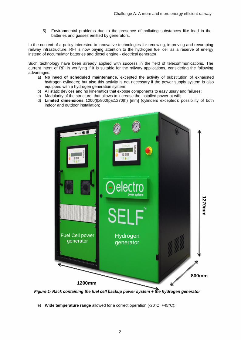
b) All static devices and no kinematics that expose components to easy usury and failures;c) Modularity of the structure, that allows to increase the installed power at will;d) Limited dimensions 1200(l)x800(p)x1270(h) [mm] (cylinders excepted); possibility of both
indoor and outdoor installation;
Figure 1- Rack containing the fuel cell backup power system + the hydrogen generator
e) Wide temperature range allowed for a correct operation (-20°C; +45°C);
800mm
1270mm
1200mm
Fuel Cell powergenerator
Hydrogengenerator
Challenge A: A more and more energy efficient railway
3
f) Respect of environment (a study of the Environment Park of Turin has pointed out that within10 years a fuel cell system, compared to lead batteries, allows to reduce of 90% the emissionof CO2 )
g) Energy saving
Single Fuel cell functionality
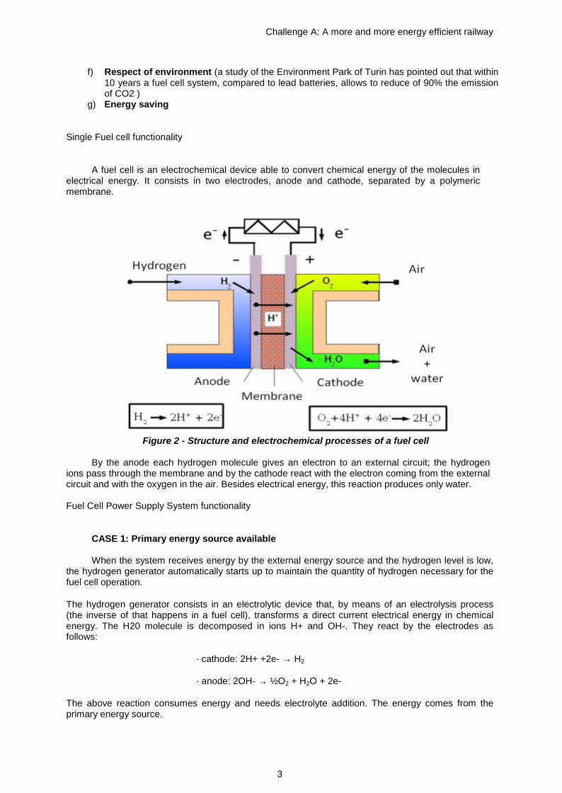
A fuel cell is an electrochemical device able to convert chemical energy of the molecules inelectrical energy. It consists in two electrodes, anode and cathode, separated by a polymericmembrane.
Figure 2 - Structure and electrochemical processes of a fuel cell
By the anode each hydrogen molecule gives an electron to an external circuit; the hydrogenions pass through the membrane and by the cathode react with the electron coming from the externalcircuit and with the oxygen in the air. Besides electrical energy, this reaction produces only water.
Fuel Cell Power Supply System functionality
CASE 1: Primary energy source available
When the system receives energy by the external energy source and the hydrogen level is low,the hydrogen generator automatically starts up to maintain the quantity of hydrogen necessary for thefuel cell operation.
The hydrogen generator consists in an electrolytic device that, by means of an electrolysis process(the inverse of that happens in a fuel cell), transforms a direct current electrical energy in chemicalenergy. The H20 molecule is decomposed in ions H+ and OH-. They react by the electrodes asfollows:
· cathode: 2H+ +2e- → H2
· anode: 2OH- → ½O2 + H2O + 2e-
The above reaction consumes energy and needs electrolyte addition. The energy comes from theprimary energy source.

Challenge A: A more and more energy efficient railway
4
When the primary electrical power source is available the generator fills the gas cylinders up with thehydrogen and/or the oxygen produced by the chemical reaction.On the contrary, when the primary electrical power source is off, the generator stops. All of thishappens automatically.The fuel cell both with the gas generator is effectively an auto- recharging Uninterruptible PowerSystem. The water utilized in the electrolysis process comes from a tank belonging to the generatoritself.
The following graph represents the pressure trend inside the hydrogen cylinders during their discharge(energy production) and recharge (hydrogen production) steps.
Figure 3 – Pressure trend during discharge and recharge of hydrogen cylinders
CASE 2: Primary energy source outage
The back-up power systems insertion takes place in two steps:
- First transitory step: the final user is fed by a traditional battery but of highly reducedcapacity whose autonomy lasts only few seconds (20”-30”), the only time necessary tothe start up of the fuel cell; meanwhile the Hydrogen generation stops;
- Second step – the fuel cell operation: the fuel cell starts up and begins to produceelectrical energy from the hydrogen contained in the cylinders and the oxygen in the airartificially blown through. The ideal operation temperature is given by a cooling circuitconsisting in a liquid-air exchanger.
The water produced in this step is stored in the tank of the gas generator.
The water deficit between the two processes of production of hydrogen and back - upenergy is equal to 20% of the total quantity used. This quantity is restored in occasion ofthe scheduled maintenance visits or automatically by the connection to a water system.
To produce 1m3 of hydrogen, the generator consumes 0,85l of water.
To produce 1kWh, a fuel cell consumes 800l of hydrogen.
Challenge A: A more and more energy efficient railway
5
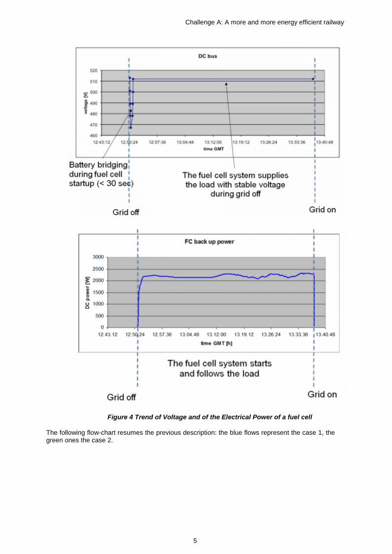
Figure 4 Trend of Voltage and of the Electrical Power of a fuel cell
The following flow-chart resumes the previous description: the blue flows represent the case 1, thegreen ones the case 2.
Challenge A: A more and more energy efficient railway
6
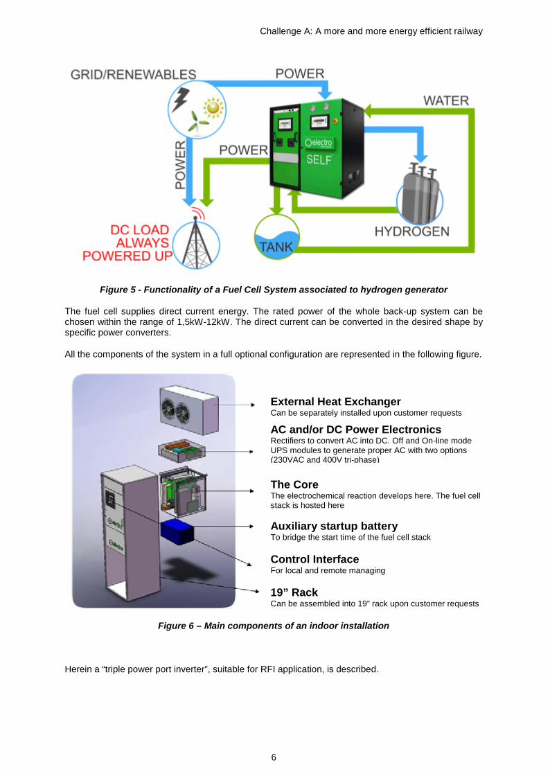
Figure 5 - Functionality of a Fuel Cell System associated to hydrogen generator
The fuel cell supplies direct current energy. The rated power of the whole back-up system can bechosen within the range of 1,5kW-12kW. The direct current can be converted in the desired shape byspecific power converters.
All the components of the system in a full optional configuration are represented in the following figure.
Figure 6 – Main components of an indoor installation
Herein a “triple power port inverter”, suitable for RFI application, is described.
External Heat ExchangerCan be separately installed upon customer requests
AC and/or DC Power ElectronicsRectifiers to convert AC into DC. Off and On-line modeUPS modules to generate proper AC with two options(230VAC and 400V tri-phase)
The CoreThe electrochemical reaction develops here. The fuel cellstack is hosted here
Auxiliary startup batteryTo bridge the start time of the fuel cell stack
Control InterfaceFor local and remote managing
19” RackCan be assembled into 19” rack upon customer requestsrequests
Challenge A: A more and more energy efficient railway
7
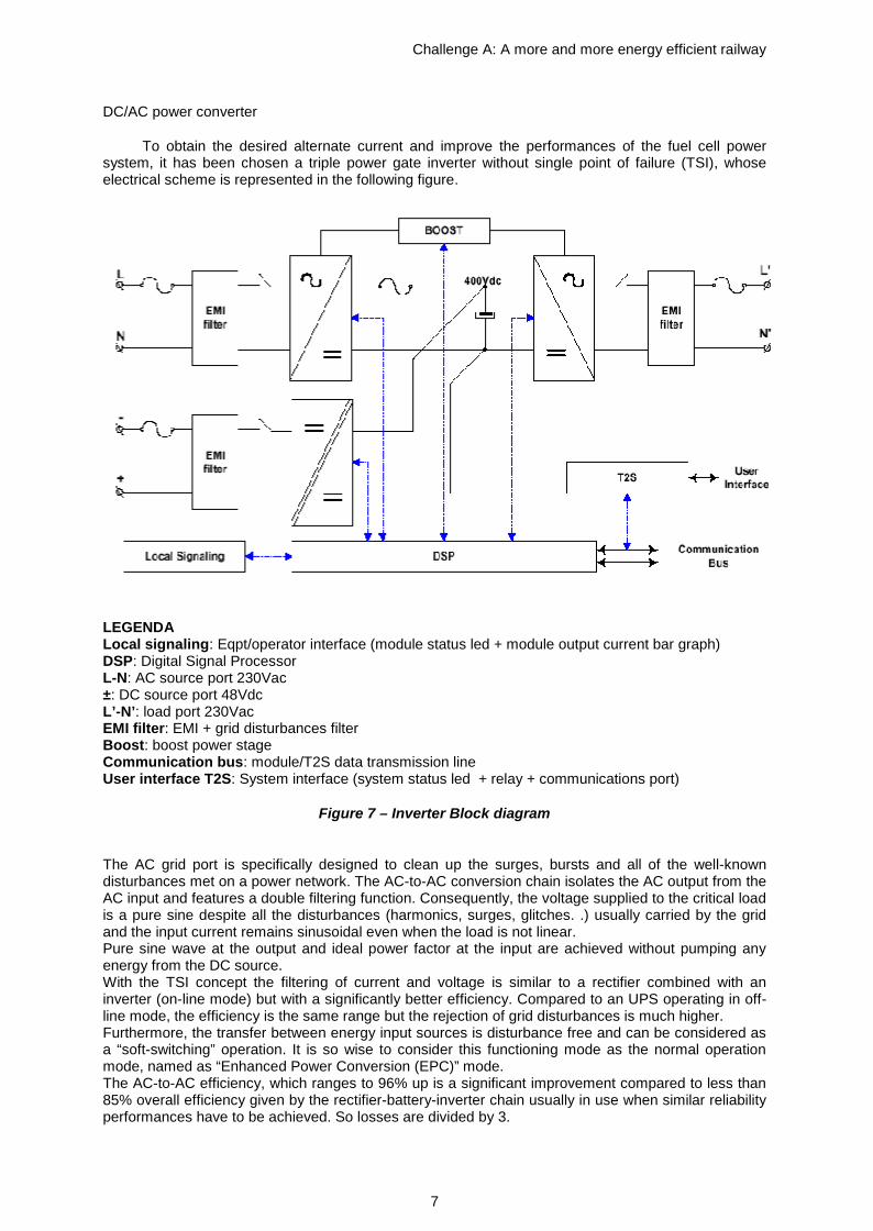
DC/AC power converter
To obtain the desired alternate current and improve the performances of the fuel cell powersystem, it has been chosen a triple power gate inverter without single point of failure (TSI), whoseelectrical scheme is represented in the following figure.
LEGENDALocal signaling: Eqpt/operator interface (module status led + module output current bar graph)DSP: Digital Signal ProcessorL-N: AC source port 230Vac±: DC source port 48VdcL’-N’: load port 230VacEMI filter: EMI + grid disturbances filterBoost: boost power stageCommunication bus: module/T2S data transmission lineUser interface T2S: System interface (system status led + relay + communications port)
Figure 7 – Inverter Block diagram
The AC grid port is specifically designed to clean up the surges, bursts and all of the well-knowndisturbances met on a power network. The AC-to-AC conversion chain isolates the AC output from theAC input and features a double filtering function. Consequently, the voltage supplied to the critical loadis a pure sine despite all the disturbances (harmonics, surges, glitches. .) usually carried by the gridand the input current remains sinusoidal even when the load is not linear.Pure sine wave at the output and ideal power factor at the input are achieved without pumping anyenergy from the DC source.With the TSI concept the filtering of current and voltage is similar to a rectifier combined with aninverter (on-line mode) but with a significantly better efficiency. Compared to an UPS operating in off-line mode, the efficiency is the same range but the rejection of grid disturbances is much higher.Furthermore, the transfer between energy input sources is disturbance free and can be considered asa “soft-switching” operation. It is so wise to consider this functioning mode as the normal operationmode, named as “Enhanced Power Conversion (EPC)” mode.The AC-to-AC efficiency, which ranges to 96% up is a significant improvement compared to less than85% overall efficiency given by the rectifier-battery-inverter chain usually in use when similar reliabilityperformances have to be achieved. So losses are divided by 3.

Challenge A: A more and more energy efficient railway
8
The TSI is able to supply 10 times its nominal output current for a time longer than 20ms in case ofdownstream short-circuit in the AC distribution. Nominal performances are kept and clean AC powersupply is guaranteed to any other load connected in parallel.The short-circuit current is also controlled in magnitude to prevent tripping of the upstream breaker.Full segregation is so ensured and is an additional guaranty that loads are kept free of disturbanceseven after failure occurrence.The internal static switch as well as the inverter of the TSI can be paralleled up to 32 units. The“synchronization communication bus” is redundant too. The communication is therefore fault-tolerant,each bus being self-sufficient to handle synchronization, load sharing and data communication.With TSI one can talk of TOTAL MODULARITY since the static switch has not to be sized according tothe eventual capacity of the AC power system, the evolution of the load being likely unpredictable.With the TSI the available AC power can be gradually increased to closely follow the loadrequirements.With TSI, the manual by-pass is no longer needed to allow replacement of the static switch. It is justlimited to cabinet maintenance purposes bearing in mind that the TSI module is hot plug andredundant.The TSI modules can be arranged in parallel to increase the available output power as well as in 3-phase configuration.
Table 1: TSI module technical characteristics
General AC Output SpecificationsEMC (immunity) EN 61000-4 Nominal voltage (AC) 230VEMC (emission) EN 55022 (Class B) Voltage range (AC) 200-240VSafety IEC 60950 Voltage accuracy 2%Cooling Forced Frequency 50Hz - 60HzIsolation Doubled Frequency accuracy 0.03%MTBF 240000 hrs THD (resistive load) < 1.5%Efficiency(Typical) EPC mode 96%
On-line mode91%Load impact recoverytime
0.4ms
Dielectric strengthDC/AC
4300Vdc Turn on delay 20sec
True RedundantSystem:– 3 disconnection
levels on AC out andDC in ports- 4 disconnectionlevels on AC in
Compliant
Nominal current:-Protected againstreverse current 10.9A
RoHS Compliant Crest factor at nominalpower:-With short circuitmanagement andprotection
3.5
I/O connection:-Protected againstinversion of polarity- Self adaptive to wideoperating conditionsand comprehensivetable oftroubleshooting codes
Terminal block
Short circuit clear upcapacity:-Available while Mains isavailable at AC input port-With magnitude controland management
10xIn for 20msec
AC Output Power Transfer PerformanceNominal O/P power 2500VA Maximum voltage
interruption0sec
O/P power (cosφ=1) 2000W Total transient voltageduration (Max)
0sec

Challenge A: A more and more energy efficient railway
9
Short timeoverload capacity
150% 5sec Environment
Permanentoverload capacity
110% Altitude above sea level < 1500m
Admissibleload power factor
Full power ratingfrom 0 inductiveto 0 capacitive
Ambient temperature -20 to +50°C
Internal temperature management and switchoff
Storage temperature -40 to +70°C
DC Input Specifications Relative humidity 95%, non condensingNominal voltage (DC) 48V Signalling & SupervisionVoltage range (DC) 40-60V Display Synoptic LEDNominal current(at 40Vdc)
56A Alarms output Dry contacts on shelf
Maximum I/P current( for 5sec)
84A Supervision Optional device
Voltage ripple 2mV Weight & DimensionsInternal voltage boundaries user selectable WxDxH
Weight102mm x 435mm x 2U
5kgAC Input Specifications Material (casing) Coated steel
Nominal voltage (AC) 230VVoltage range (AC)(adj)
185-265V
Power factor > 99%Frequency range(select)
50Hz - 60Hz
Synchronization range 47-53Hz / 57-63Hz
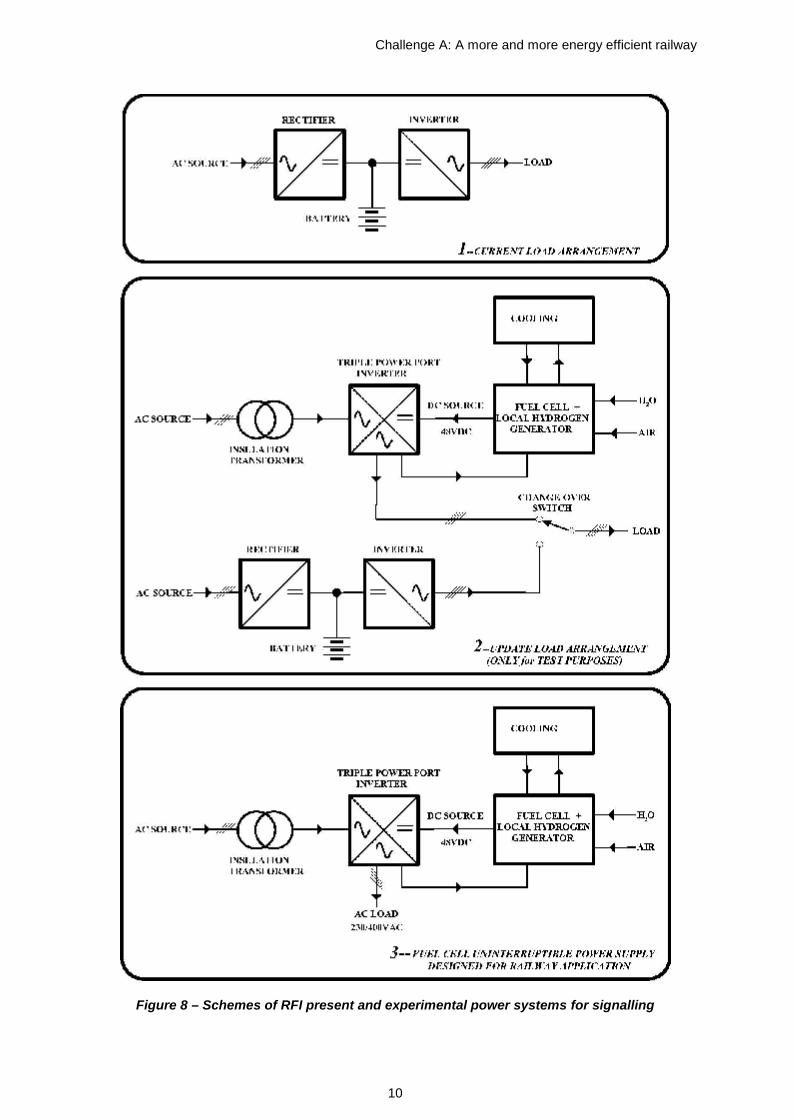
Fuel cell system for RFI application
As illustrated in the following figure (first scheme), a part of the power system for RFI signallingequipments currently consists in a three phase rectifier – inverter chain. The inverter supplies the loadand in ordinary conditions receives energy by the rectifier. In emergency conditions it receives energyby traditional batteries.
During the fuel cell system experimentation, the load will be normally fed by the fuel cell system but, ifnecessary, commutation on the traditional system will be possible (second scheme in the following).
The definitive solution provides only the fuel cell power system as back-up source (third scheme).
Challenge A: A more and more energy efficient railway
10
Figure 8 – Schemes of RFI present and experimental power systems for signalling

Challenge A: A more and more energy efficient railway
11
Table 2: Data sheet of the components used in the application
GeneralDimensions 1200 x 1200 x 1600mmWeight 470kgCooling LiquidOperating temperature +5°C / +45°C (indoor) - -20°C / + 45°C (outdoor)Installation Indoor or outdoorNoise 0dB (stand by mode)Relative humidity 0% - 95% non condensingAltitude 0m asl – 2000m aslBack up time 4kW/8hHydrogen storage cylinder #4Stack life expectancy 2000h (continuous production mode) – 87000h (10 years) stand by mode)Hydrogen production modeElectrolyser power consumption 3kWCompressor average power con. 0,7kWInput voltage 230Vac / 50Hz single phase or 400Vac three-phaseSpecific water consumption 0.85 liters per m3 of produced H2
H2 outlet pressure 10barH2 outlet pressure with booster 150barH2 production up to 550l/hNoise 65dBPower production modePower generation 6kWNominal output voltage 48VdcOutput voltage adj.ble window 46 – 57VdcNominal output current 125A@48VdcH2 consumption at max power 5000l/h
Fuel purity Hydrogen 2.5 – 5.0Fuel pressure supply 2.5 barNoise 65dBCommunication and managementControl panel LCD status and control consoleHMI Display on boardCommunication Potential free contact, CANOpen (GSM and RS232/RS485), TCP/IPSafetyProduct standard ISO 22734-1EMCD EN61000-6-2; EN61000-6-3Safety EN60204-1; EN13611; EN62282; EN60950-1Storage solutionAuxiliary startup unit 55Ah AGM batteryCabinet for 4 cylinders 1200 x 550 x 2100mm
For high levels of power (12kW) oxygen cylinders are also necessary. Their number must be equal tohalf of that of hydrogen cylinders. In these cases the Direct Oxygen technology (DOX) is adoptedbecause it allows to obtain more power and requires less auxiliary components (e.g. air blower is nomore necessary).