backflow - waterworks services & products for professionals · pdf fileply are connected....
TRANSCRIPT


Phone: 800-EJP-24HR (357-2447) • Fax: 207-582-5637
I
Backflow Prevention Devices I-1
H-1www.ejprescott.com I-1
Cross Connection• – Arrangement of piping which allows a potable water supply to become connected to a line which contains a contaminant.
• Back-Siphonage – Reversal of normal flow direction due to a negative pressure in the supply piping.
Backpressure Backflow• – Reversal of normal flow direction due to an increase in downstream pressure.
Thermal Expansion • - Once a backflow preventer is installed a system becomes closed. After this point as the temperature rises, the water will expand. Without proper room for expansion there is an increased risk of damage to the plumbing system.Potential Results• – Leaking TCP valve or other relief valves, leaking pipes, blown joints, ruptured boilers, ruptured hot water heaters, serious burns, water dam-age, mold, mildew, water hammer, and many more symptoms may result.
Terminology Associated with Backflow Prevention
Degree of Hazard• – Potential threat to water quality of a particular cross connection or chemical.First Line of Defense• – Backflow Preventers located just prior to the contaminant source, or located at each fixture which might allow a contaminant to enter the potable water system.Containment• – Backflow Preventers located at points where public water supply and private water sup-ply are connected. This “Second Line of Defense” ensures that the public water quality is not compromised if the first line of defense is tampered with, altered, or is not adequately serviced.Cross Connection Control Program• – This is a com-bined cooperative effort between plumbing and health officials, waterworks companies, property owners, and certified testers to establish and administer guidelines for controlling cross connections and implementing means to ensure their enforcement so that the public potable water supply will be protected both in the city main and within buildings. The elements of a program define the type of protection required and responsibility for the administration and enforcement. Other elements ensure continuing education programs.
Backflow Terminology
Selection Guidelines for Backflow Prevention Assemblies
CONDITIONREDUCED PRESSURE
(RP)
DOUBLE CHECK
(DBL CK)
PRESSURE VACUUM BREAKER
(PVB)
ATMOSPHERIC VACUUM BREAKER
(AVB)
DUAL CHECK
(DC)
DUAL CHECK W/ATMOSPHERIC
PORT (DCAP)
Continuous Pressure ✔ ✔ ✔ ✔ ✔
Possible Back Pressure ✔ ✔ ✔ ✔
Possible Backsiphonage ✔ ✔ ✔ ✔ ✔ ✔
Non-Toxic ✔ ✔ ✔ ✔ ✔ ✔
Toxic ✔ ✔ ✔

Backflow Prevention Devices I-2
H-2 Phone: 800-EJP-24HR (357-2447) • Fax: 207-582-5637I-2 www.ejprescott.com
TANK TANK TANK TANK
AIR GAP
WATTS NO. 909
MAIN
STRAINER
Basic Types of Testable Backflow
Preventers
Reduced Pressure Zone (RPZ) Backflow Preventer
PurposeFor high hazard cross-connections and continuous
pressure applications.
Description of Backflow DeviceTwo independent check valves with intermediate dump-
ing relief valve, shut-off valves, and ball type test cocks.
Testable Double Check Valve Assembly
PurposeFor low hazard cross-connections and continuous
pressure applications.
Description of Backflow DeviceTwo independent check valves with shut-off valves
and ball type test cocks.
ApplicationsReduced Pressure Backflow Devices should be used
whenever the non-potable source is more of a contaminant than a pollutant. Basically, they are applied as main line protection to protect the municipal water supply, but should also be used on branch line applications where non-potable fluid would constitute a health hazard, such as boiler feed lines, commercial garbage disposal systems, industrial boilers (see typical installations below).
Where to UseReduced Pressure Zone Devices may be used on
all direct connections which may be subjected to back-pressure or back-siphonage, and where there is the possibility of contamination by the material that does constitute a potential health hazard.
Typical Installations:Main Supply Lines • Laboratory Equipment• Commercial Boilers • Waste Digesters• Cooling Towers • Car Washes• Hospital Equipment • Sewage Treatment• Processing Tanks•
Applications Double Check Valve Assemblies may be used where
the degree of hazard is low to intermediate, meaning that the non-potable source is polluted rather than contaminated. The degree of hazard is often determined by local Inspec-tion Departments and therefore such departments should be questioned in order to comply with local regulations.
Where to UseA Double Check Valve Assembly may be used as
protection of all direct connections through which foreign material might enter the potable system in concentration and which would constitute a nuisance or be aesthetically objectionable, such as air, steam, food or other material which does not constitute a health hazard.
Typical Installations:Main Supply Lines• Food Cookers• Tanks and Vats• Lawn Sprinklers• Fire Sprinkler Lines•

Phone: 800-EJP-24HR (357-2447) • Fax: 207-582-5637
I
Backflow Prevention Devices I-3
H-3www.ejprescott.com I-3
Dual Check Backflow
Preventers
Series #7 Dual Check Backflow Preventer - ½" thru 1¼"
Residential Protection for Public Water Supply
The # 7 Dual Check Backflow Preventer is designed for containment control programs and installation at the residential water meter or service entrance.
The Dual Check Backflow Preventer provides maxi-mum protection for the public water supply when utilized in comprehensive total containment programs. The Dual Check is designed to support the local or state plumbing code requirements for each premise served.
It is generally understood that the water purveyor has no authority to conduct plumbing inspections and that residential homes often fall into a category of non-compliance with the code, resulting in a potential health hazard for the consumer and the community water supply. Therefore, a comprehensive program to protect safe drinking water will consist of the following three major components as conditions of the agreement or contract for receiving service from the public water system.
The user must certify that his domestic water system is • in compliance with the plumbing code — The first line of defense.The user must install a Dual Check Backflow Preventer, • located at the water meter, as prescribed by the purveyor of water. — The second line of defense.In addition to providing an ample supply of qual-• ity drinking water, the supplier must also provide information to the user on prevention of inadvertent contamination or pollution of that water once it has entered the domestic water system. This is basi-cally a descriptive explanation of the local plumbing code — Education.
NOTE: Team EJP has the information which explains why it is so important to protect both the public water supply and domestic water system.
Series 7 straight line poppet type construction minimizes pressure drop and provides smooth flow characteristics. It is not adversely affected by normal line pressure surges, will not cause water hammer and operates without chatter or vibration. It can be installed horizontally or vertically. Tested and certified to meet or exceed the 1988 revision of ANSI/ASSE Standard 1024 for “Dual Check Valve Type Backflow Preventers.”
NOTES:The #7 Dual Check is 100% lead free. • See Section H for K-Horns and Pack Joint Assemblies. •
K-Horn Dual Check The #7 Dual Check Valve is attached to the outlet side
of the K-Horn meter setter and connected to the inside service pipe with a Pack Joint Assembly.
In-Line Dual Check Valves
FEIP X FEIP
#7 Dual Check Backflow Preventer
SpecificationsThe Dual Check Backflow Preventer shall meet the domestic requirements of ANSI/ASSE Standard 1024, and bear the seal of approval. It shall be bronze-bodied and include not less than one union, with the union nut drilled to accept a tamper-proof lock wire. A brass identification tag shall be securely attached to the valve body by corrosion-resistant mechanical fasteners. The Dual Check shall be Watts Regulator Company’s Series 7, or approved equal.
Meter x FEIP or Pack Joint Outlets
METER SIZE
TUBING SIZE
PRODUCT NUMBER
FEIP OUTLET
PACK JOINT OUTLET
5⁄8" 3⁄4" NS 520465⁄8" x 3⁄4" 3⁄4" 52049 52047
3⁄4" 3⁄4" 52049 520471" 1" NS 52048
DESCRIPTION PRODUCT NUMBER
#7 DCBF Prev. 1-3K L/C 52035#07S DCBF Prev. 4K L/C 51254 3
DESCRIPTION THREAD SIZE
PRODUCT NUMBER
3⁄4" #7 Dual Check BF IP x IP 3⁄4" 512431" #7 Dual Check BF IP x IP 1" 51260
Refer to MBS, Section T for Backflow Installation
and Testing Services
Backflow Prevention Devices I-4
H-4 Phone: 800-EJP-24HR (357-2447) • Fax: 207-582-5637I-4 www.ejprescott.com
Double Check Backflow
Preventers
Double Check Valve Assembly Backflow Preventers
Watts Double Check Valve Assemblies are designed to protect the potable water supply in accordance with national plumbing codes and local water authority requirements. The 007 and 709 Series can be applied to a variety of in-stallations where the degree of hazard is considered low to intermediate. This includes containment at the service line entrance, and where approved for specific installations.
Series 007 are tested and certified under the follow-ing standards: ASSE Standard 1013 and 1015, AWWA C510-92, CSA B64.5, FCCCHR of USC Manual, Section 10, and are listed by IAPMO (UPC) and SBCCI (Standard Plumbing Code).
IMPORTANT: Inquire with governing authorities for local installation requirements.
Watts Series 007QT Sizes ¾" – 2"
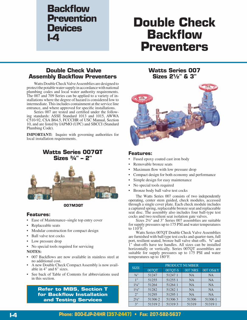
Watts Series 007 Sizes 2½" & 3"
Features:Ease of Maintenance–single top entry cover• Replaceable seats• Modular construction for compact design• Ball valve test cocks• Low pressure drop• No special tools required for servicing•
NOTES:007 Backflows are now available in stainless steel at • no additional cost.A new Double Check Compact Assembly is now avail-• able in 4" and 6" sizes.See back of Table of Contents for abbreviations used • in this section.
007M3QT
Features:Fused epoxy coated cast iron body• Removable bronze seats• Maximum flow with low pressure drop• Compact design for both economy and performance• Simple design for easy maintenance• No special tools required• Bronze body ball valve test cocks•
The Watts Series 007 consists of two independently operating, center stem guided, check modules, accessed through a single cover plate. Each check module includes a captured spring, replaceable bronze seat and replaceable seat disc. The assembly also includes four ball-type test cocks and two resilient seat isolation gate valves.
Sizes 2½" and 3" Series 007 assemblies are suitable for supply pressures up to 175 PSI and water temperatures to 110°F.
Watts Series 007QT Double Check Valve Assemblies are furnished with ball type test cocks and quarter-turn, full port, resilient seated, bronze ball valve shut-offs. ¾" and 1" shut-offs have tee handles. All sizes can be installed horizontally or vertically. Series 007QT assemblies are suitable for supply pressures up to 175 PSI and water temperatures up to 180°F.
007 Shown with NRS Valves
SIZEPRODUCT NUMBER
007QT 007QT-S 007 NRS 007 OS&Y¾" 51247 51247 1 NA NA1" 51255 51255 1 NA NA
1¼" 51264 51264 1 NA NA1½" 51282 51282 1 NA NA2" 51295 51295 1 NA NA
2½" 51306 2 51306 3 51306 51306 13" 51319 2 51319 3 51319 51319 1
Refer to MBS, Section T for Backflow Installation
and Testing Services

Phone: 800-EJP-24HR (357-2447) • Fax: 207-582-5637
I
Backflow Prevention Devices I-5
H-5www.ejprescott.com I-5
Double Check Backflow
Preventers & Strainers
Series 709 Double Check Valve Assembly Sizes 2½" – 10"
Features:Resilient Wedge gate valve shut-offs - UL/FM approved• FDA approved epoxy coated check valves (inside • and out)Removable bronze seats• Stainless steel internal parts• Maximum flow with low pressure drop• Simple design for easy maintenance• No special tools required•
Series 709 2½"–10" sizes provide backflow protection in cross-connection control and containment. These assemblies are suitable for supply pressures up to 175 PSI and water temperatures to 110°F.
The assemblies are tested and certified under the following standards for reduced pressure backflow preventers; ASSE No. 1015, AWWA C510-92, CSA B64.5, FCCCHR of USC Manual Section 10, U.L. Classified File No. EX3185. Listed by IAPMO (UPC): SBCCI (Standard Plumbing Code).
NOTE:See back of Table of Contents for abbreviations used • in this section.
709 Shown with Optional NRS RW Valves
Cast Iron Strainers
Model 77F-D-FDA
The Series 77F-D-FDA “Y” type strainers have a stainless steel screen* and a cast iron body with two coats of fusion-bonded epoxy applied to both the interior and exterior. FDA approved for potable water and food contact. Ideal for liquid service where a non-corrosive construction/clean cosmetic appearance is required.
The Series 77F-D-FDA is available in standard 125 lb. or 250 lb. faced and drilled flanges. 125 lb. flanges are suit-able for supply pressures up to 200 PSI at 100°F WOG.* A wide variety of screen opening sizes are available. Please contact your local Team EJP sales office for assistance.
SIZEPRODUCT NUMBER
709 NRS RW
709 OS&Y RW
EPOXY CTD. STRAINER
2½" 51308 1 51308 513073" 51322 1 51322 513204" 51326 51326 1 513276" 51331 51331 1 513328" 51336 51336 1 5133710" 51341 51341 1 51343
Refer to MBS, Section T for Backflow Installation
and Testing Services

Backflow Prevention Devices I-6
H-6 Phone: 800-EJP-24HR (357-2447) • Fax: 207-582-5637I-6 www.ejprescott.com
Double Check Backflow
Preventers
MasterSeries 850 Double Check Assembly
For use in all nonhealth hazard (nontoxic) connec-tions including: irrigation systems, fire sprinkler systems, in-plant commercial and industrial plumbing systems.
MasterSeries 856 Double Check Detector Assembly
For use in fire sprinkler/standpipe/distribution systems requiring detection of unauthorized water use (nontoxic).
DCBF PREVENTER
850DC
SIZE PRODUCT NUMBER
½" 51237 1¾" 512411" 51253 1
1½" 512662" 51289
DCBF DETECTOR ASSEMBLY 856 OS&Y
SIZE PRODUCT NUMBER
3" 51317 24" 513246" 513298" 51334
Refer to MBS, Section T for Backflow Installation
and Testing Services

Phone: 800-EJP-24HR (357-2447) • Fax: 207-582-5637
I
Backflow Prevention Devices I-7
H-7www.ejprescott.com I-7
Reduced
Pressure Zone Backflow
Preventers
Watts “High Capacity Relief” Series 909 (RPZ)
Backflow Preventer
“Series 909 protects against back-si-phonage and backpressure with both
checks fouled.”The principle is simple, but it’s used to solve a complex
safety problem. The Series 909 is the only backflow preven-ter available that provides protection against simultaneous back-siphonage and back pressure backflows.
A patented built-in vacuum relief is designed around the air-in/water-out principle. The valve has two channels: one for air, one for water. When the relief valve opens, one channel admits air to the top of the reduced pressure zone. The other channel then drains to atmosphere. Therefore, if both check valves foul and simultaneous negative and positive backpressures develop, the relief valve will stop potential backflow by providing “high capacity” relief .
Series 909 RPZ 2½" – 10"
Series 909 RPZ ¾" – 2"
StandardsTested and certified under the following standards for re-duced pressure principle backflow preventers: ASSE No. 1013, AWWA C511-92, CSA B64.5, FCCC-HR of USC Manual 8th Edition Section 10, U.L. Classified File No. EX3185 (sizes 2½" thru 10"). Listed by IAPMO PS-31-(UPC), SBCCI (Standard Plumbing Code). Check local codes for approval of vertical installations.
Relief Valve
No. 909QT-S
Use ¾" – 2" 909s for backflow protection in both cross-connection control and containment at the service entrance. The 909 “high capacity” relief incorporates the “air-in/water-out” principle and substantially improves the relief valves discharge performance. The emergency condition of combined back-siphonage and back-pressure with both checks fouled can defeat the effectiveness of a standard RPZ backflow preventer. This device may be installed in a verticle position in accordance with ASSE 1013 standard.
909 Shown with Optional OS&Y RW Valves
2½" –10" sizes provide backflow protection for both cross-connection control and containment with their unique patented design incorporating the “air-in/water-out” prin-ciple. Normally furnished with non-rising stem (NRS) resilient wedge gate valves.
NOTE: RPZ compact assembly is now available in 4" and 6" sizes. Contact your nearest Team EJP Sales office.
IMPORTANT NOTE: Inquire with governing authorities for local installation requirements.
Refer to MBS, Section T for Backflow Installation
and Testing Services

Backflow Prevention Devices I-8
H-8 Phone: 800-EJP-24HR (357-2447) • Fax: 207-582-5637I-8 www.ejprescott.com
Reduced Pressure Zone
Backflow Preventers
Designed for the protection of potable water supplies in accordance with national plumbing code and water author-ity requirements. Used for high hazard cross-connections in plumbing systems or for containment at the service line entrance.
Two in-line, independent check valves with an inter-mediate relief valve, NPT body connections and ball type test cocks. Series 009QT has quarter-turn, full port, resilient seated bronze ball valve shut-offs (½"–2"). ¾" and 1" shut-offs have tee handles. Sizes 2½" and 3" have NRS-RW gate valve shut-offs.
009M2QT
NOTES:
UL/FM approved backflow preventers must include UL/FM approved OS&Y valves.• See page I-5 for information on strainers supplied with 909 Backflow Preventers.• See back of Table of Contents for abbreviations used in this section.•
Watts Standard Series 009 RPZ Backflow Preventer
MasterSeries 860 Reduced Pressure Assembly
For use in all health hazard (toxic) connections includ-ing: irrigation systems, hospitals, morgues, medical/dental facilities, industrial/chemical plants and boiler feeds.
BACKFLOW SIZE
PRODUCT NUMBERS
009QT 009QT-S 909QT 909QT-S 909NRS RW 909 OS&Y RW 860RP
½" 51235 51237 NA NA NA NA 51236
¾" 51252 3 51252 4 51252 51252 2 NA NA 51241 1
1" 51257 51257 1 51256 51256 2 NA NA 51253 2
1¼" 51263 51263 1 51262 51262 2 NA NA 51285
1½" 51268 51268 1 51267 51267 2 51267 1 NA 51289 1
2" 51292 3 51292 4 51292 1 51292 2 51292 NA NA
2½" 51305 4 51305 5 51304 51304 1 51305 51305 1 NA
3" 51318 4 51318 5 51321 51321 1 51318 51318 1 NA
4" NA NA NA NA 51325 51325 1 NA
6" NA NA NA NA 51330 51330 1 NA
8" NA NA NA NA 51335 51335 1 NA
10" NA NA NA NA 51340 51340 1 NA
Refer to MBS, Section T for Backflow Installation
and Testing Services
Phone: 800-EJP-24HR (357-2447) • Fax: 207-582-5637
I
Backflow Prevention Devices I-9
H-9www.ejprescott.com I-9
TK-99D Test Kit
Backflow Accessories
Watts TK Test Kits for Backflow Preventers
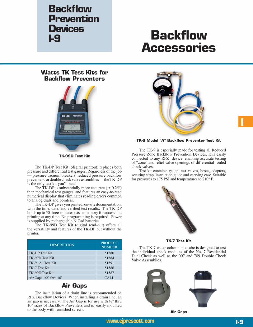
TK-9 Model “A” Backflow Preventer Test Kit
The TK-9 is especially made for testing all Reduced Pressure Zone Backflow Prevention Devices. It is easily connected to any RPZ device, enabling accurate testing of “zone" and relief valve openings of differential fouled check valves.
Test kit contains: gauge, test valves, hoses, adaptors, securing strap, instruction guide and carrying case. Suitable for pressures to 175 PSI and temperatures to 210° F.
Air GapsThe installation of a drain line is recommended on
RPZ Backflow Devices. When installing a drain line, an air gap is necessary. The Air Gap is for use with ½" thru 10" sizes of Backflow Preventers and is easily mounted to the body with furnished screws.
The TK-7 water column site tube is designed to test the individual check modules of the No. 7 Residential Dual Check as well as the 007 and 709 Double Check Valve Assemblies.
TK-7 Test Kit
Air Gaps
The TK-DP Test Kit (digital printout) replaces both pressure and differential test gauges. Regardless of the job — pressure vacuum breakers, reduced pressure backflow preventers, or double check valve assemblies — the TK-DP is the only test kit you’ll need.
The TK-DP is substantially more accurate ( ± 0.2%) than mechanical test gauges and features an easy-to-read numerical display that eliminates reading errors common to analog dials and pointers.
The TK-DP gives you printed, on-site documentation, with the time, date, and verified test results. The TK-DP holds up to 50 three-minute tests in memory for access and printing at any time. No programming is required. Power is supplied by rechargeable NiCad batteries.
The TK-99D Test Kit (digital read-out) offers all the versatility and features of the TK-DP but without the printer.
DESCRIPTION PRODUCT NUMBER
TK-DP Test Kit 51580TK-99D Test Kit 51584TK-9 “A” Test Kit 51591TK-7 Test Kit 51586TK-99E Test Kit 51587Air Gaps 1/2" thru 10" CALL

Phone: 800-EJP-24HR (357-2447) • Fax: 207-582-5637
I
Backflow Prevention Devices I-11
H-11www.ejprescott.com I-11
Thermal Expansion Solutions
FOR SAFETY…Always make sure there is a functional temperature
and pressure relief valve before you install a Backflow Preventer. This will prevent a dangerous condition, but does not prevent plumbing system damage. Most hot water heater manufacturers’ warranties become void if a Backflow Preventer is installed without a means of reliev-ing excess pressure.
Watts® Governor 80-M1
Ball Cock and Relief Valve for 80 PSI Static Pressure Code Compliance.
The unique Watts® Governor 80-M1 is a multipurpose device, anti-siphon ball cock, Backflow Preventer, thermal expansion pressure relief valve and a ball cock water closet fill valve. It allows contractors and code officials to eas-ily design a safer water system without extra plumbing for expansion tanks or auxiliary relief valves to alleviate excessive pressure from thermal expansion.
The idea is simple and revolutionary. One triple-function device offers all these capabilities:
Limits and governs the domestic water system preset • static pressure to 80 psi, as required by plumbing codes.
Protects the temperature and pressure safety relief • valve on the water heater from unnecessary relief, reserving it for its primary function.
Eliminates the need for more expensive thermal ex-• pansion tank or an auxiliary relief valve that serves the same function.
Prevents backflow from water closets, a serious • cross connection.
Features and Specifications:The Watts• ® Governor 80-M1 incorporates the simplest “full flow” ball cock principle available. It has a large, non-clogging flow way which permits quiet operation and snap-action shut-off under a wide range of flow pressures. Durable PVC and Celcon® are used in the unified construction which makes the “Watts® Governor 80” completely non-electrolytic and non-corrosive. Reliability is built in from the beginning.
The Watts• ® Governor 80-M1 meets IAPMO, ASSE and CSA requirements for anti-siphon ball cocks. All materials in contact with water are FDA approved. The relief valve is set at a standard of 80 psi to meet existing codes and is non-adjustable. However, other settings of 60, 100 and 125 psi are available with maximum operating temperatures of 140°F. Standard lengths are 10", 11½" or 12½".
You can replace an existing water closet fill valve with the Watts® Governor 80-M1. A removable
cap ring provides for easy service.
NOTE: Also available in 10" and 12½" sizes.
DESCRIPTION PRODUCT NUMBER
Watts® Governor 80-M1-11½" 51598
NOTES:See back of Table of Contents for abbreviations used • in this section.

Restrained Joint
PVC Pressure Pipe
The Certa-Lok Yelomine piping system can provide a unique solution to many of your speciality and standard piping system needs, either temporary or permanent applica-tions. Certa-Lok Yelomine’s jointing system and physical properties allow this pipe to be used in a broad range of piping applications.
Certa-Lok Yelomine pipe offers a reusable, easy to assemble, fully self-restrained spline locked joint, virtually eliminating thrust blocking. A gasket provides a hydraulic seal while the spline securely locks the coupling to the pipe.
Certa-Lok Yelomine is manufactured from a specially formulated PVC compound which contains impact modi-fiers and UV (ultra violet) inhibitors. These modifiers and inhibitors provide a higher impact strength over an extended period of time and allow Certa-Lok Yelomine to be used in above-ground, exposed applications.
ToughnessSpecial PVC compounds used in the manufacturing
of Certa-Lok Yelomine pipe give it high tensile and impact strength. Yelomine pipe also has excellent resistance to chemicals and scale build-up and it can't corrode.
FlexibilityCerta-Lok Yelomine pipe can bend around many
obstacles, thus reducing the number of fittings required. When assembled, couplings (joints) are not affected by standard pipeline bending.
Certa-Lok™ Yelomine™ PVC Restrained Joint Pressure Pipe
SafetyCerta-Lok Yelomine pipe has the highest physical
strength available in PVC (2000 psi design stress). This means it has a longer life and is more reliable than roll grooved PVC. Yelomine pipe is self-extinguishing.
LightnessLight weight means pipe can be handled manually in
convenient 20' sections.
Abrasion and Chemical ResistanceCerta-Lok Yelomine pipe will outlast steel pipe in slurry
applications because it doesn’t rust or corrode. Its chemical resistance exceeds the requirements of ASTM D-1784 and it is not damaged by acids found in mine water.
Sustained PressureAn important property of plastic pipe is its long term
strength under pressure. This property is best expressed by a stress vs. time curve which becomes a straight line when plotted on logarithmic scales. Data for this straight line is obtained by conducting long term hydrostatic pressure tests in accordance with ASTM D-1598 and ASTM D-2937. This plot is known as the stress regression line and basically is a response to applied internal pressure over a long period of time.
The hydrostatic design basis is chosen at the 100,000 hour value (11.4 years). This minimum design stress life of 100,000 hours at 4,000 psi is modified by a safety factor of 2:1, resulting in a pipe life expectancy of over 100 years at 2,000 psi design stress. As shown in the graph below, test samples of Yelomine exceed the minimum requirement of 4,000 psi at 100,000 hours.
Impact StrengthThe PVC compounds used in Yelomine pipe greatly
exceed the impact strength of conventional Type 1 PVC. Impact strength tests are regularly made on Yelomine pipe in accordance with the requirements of ASTM standard D-2444.
Average impact values are two to four times greater than the impact resistance of conventional PVC.
PipeA-30
Phone: 800-EJP-24HR (357-2447) • Fax: 207-582-5637A-30 www.ejprescott.com

ARestrained Joint
PVC Pressure Pipe
Performance Characteristics and Specifications
CertainTeed Yelomine PVC Pipe is made from a special formulation of Polyvinyl Chloride, Type 1, Grade 1, 2000 psi design stress material, Class 12454B in accordance with ASTM D-1784 . The Yelomine PVC formulation contains additional impact modifiers and ultraviolet inhibitors to give it higher impact strength over a longer period of time.
Yelomine meets all PVC Pipe requirements as specified in the ASTM Standard Specification D-2241 for Polyvinyl Chloride Plastic Pipe, (pressure rated SDR pipe).
CertainTeed Yelomine Certa-Lok joints meet ASTM D-3139, Joints for Plastic Pressure Pipes Using Flexible Elastomeric Seals.
Rubber rings meet ASTM F-477, Standard Specifi-cation for Elastomeric Seals (Gaskets) for Joining PVC Pipe.
NOTES:20' standard laying length•Also available in SDR 41 and SDR 32.5•See Section B for Restrained Joint PVC Pressure Fittings. •
PIPE SIZE
O.D(in.)
O.D. 1(in.)
CLASS125 140 160 200 250
MINIMUM WALL THICKNESS (inches)
2" 2.362 3.20 — — — — .1403" 3.503 4.38 — — — — .2064" 4.488 5.47 — — .175 .214 .2656" 6.614 7.84 .204 — .255 .316 .3908" 8.622 10.19 .265 — .332 .410 —10" 10.748 12.44 .331 — .413 — —12" 12.755 14.65 .392 — .490 — —14" 14.015 16.00 — .612 — — —16" 15.984 17.50 .615 — — — —
PIPE SIZE O.D
PRODUCT NUMBERSSDR 25 SDR 26
2" 2.362 — —3" 3.503 — —4" 4.488 — —6" 6.614 — 221038" 8.622 — 2215910" 10.748 — 2218312" 12.755 — 2222814" 14.015 — —16" 15.984 — —
SIZE O.DPRODUCT NUMBERS
SDR 21 SDR 172" 2.362 — 220173" 3.503 — 220354" 4.488 22080 220796" 6.614 22102 221018" 8.622 22158 2215710" 10.748 22182 —12" 12.755 22227 —14" 14.015 — —16" 15.984 — —
CertainTeed Yelomine PVC Pipe has Potable Water Service Certification in accordance with NSF No. 14 (National Sanitation Foundation Standard) for Ther-moplastic materials, pipe fittings, valves, traps, and joining materials.
MINIMUM TYPICAL PROPERTY VALUESPROPERTY MIN. VALUE ASTM NO.
Tensile Strength 7,000 psi D-638Modulus of Elasticity 400,000 psi D-638
Izod Impact 0.65 ft. lbs./in. of notch D-256
Deflection Temperature 150°F D-648Flammability Self-Extinguishing D-635Chemical Resistance B D-543
Phone: 800-EJP-24HR (357-2447) • Fax: 207-582-5637
PipeA-31
www.ejprescott.com A-31

Assembly and Disassembly Start — Couplings and pipe have matching grooves. Just 1. wipe them clean and apply a small amount of lubricant to rubber rings and pipe ends.
Push — Couplings slip easily onto pipe. When pipe end 2. seats against stop, grooves are automatically aligned for spline insertion.
Lock-Up — Nylon spline is pushed into aligned grooves 3. around the pipe’s circumference, securely locking pipe to coupling. Special rubber seals provide bottle-tight fit. Assembled coupling is so strong that no blocking is needed to support it.
Tear-Down — Nylon spline is pulled out and pipes 4. pulled apart. Use silicone lubricant (available through your local Team EJP sales office) if pipe is to be dis-assembled.
Non-Permanent Use Certa-Lok JointThis product offers a Teflon coated “O”-Ring, which
is blue-black in color. Non-Permanent Use Certa-Lok Yelo-mine minimizes assembly and disassembly effort required to install, remove and reinstall a system.
The Non-Permanent Use Certa-Lok joint is typically used in above-ground, exposed installations and where disassembly and reuse may be required.
Non-Permanent Use Certa-Lok joint is NOT recom-mended in buried installations or installations where the joint is subject to long-term or excessive misalignment due to external forces such as earth loads, live loads, etc.
2" through 6" sizes typically do not require lubricant for assembly due to the Teflon coating on the “O”-Rings. 8" through 16" sizes require lubricant to assemble.
Restrained Joint
PVC Pressure Pipe
NOTES: Non-Permanent and Permanent Use joints are totally interchangeable and can be mixed in the same piping system. The •only difference is the “O”-Ring gasket.If in doubt as to which system to use contact your local Team EJP sales office for assistance.•
Permanent Use Certa-Lok JointThis product is the same as Non-Permanent Use with
the exception that the “O”-Ring used, has a slightly larger cross section and is not Teflon coated. The joint assembles easily using lubricant. Disassembly can be achieved, but can be extremely difficult depending on the diameter of the pipe being used.
Permanent Use Certa-Lok joint is intended for use in buried applications, bridge, river and road crossings and all installations that would be considered permanent, as well as installations that would encounter joints being subject to long-term or excessive misalignment due to external forces such as earth loads, live loads, etc. This joint requires lubricant to assemble.
PipeA-32
Phone: 800-EJP-24HR (357-2447) • Fax: 207-582-5637A-32 www.ejprescott.com
