backwall ground stud
TRANSCRIPT

1
SS 1033950 New Cascadia trailer receptaclebackwall grounding stud
SS 1033950 New Cascadia trailer receptacle back wall grounding stud
Applicable Vehicles
New Cascadia
Symptoms
Trailer lights dim or blinking, possible ABS codes including 11/520216/19.
Issue
Some New Cascadia vehicles built with the seven way primary cable receptacle mounted at the lower left hand
back of cab may have the trailer grounding circuit incorrectly attached to the interior back wall.
Solution
See the attached document for corrective action.

P4 Back wall Ground Stud Correction
See attached visuals and notes for correction of possible incorrectly installed grounding concern
Disconnect batteries prior to performing this work!

P4 Back wall Ground Stud Correction
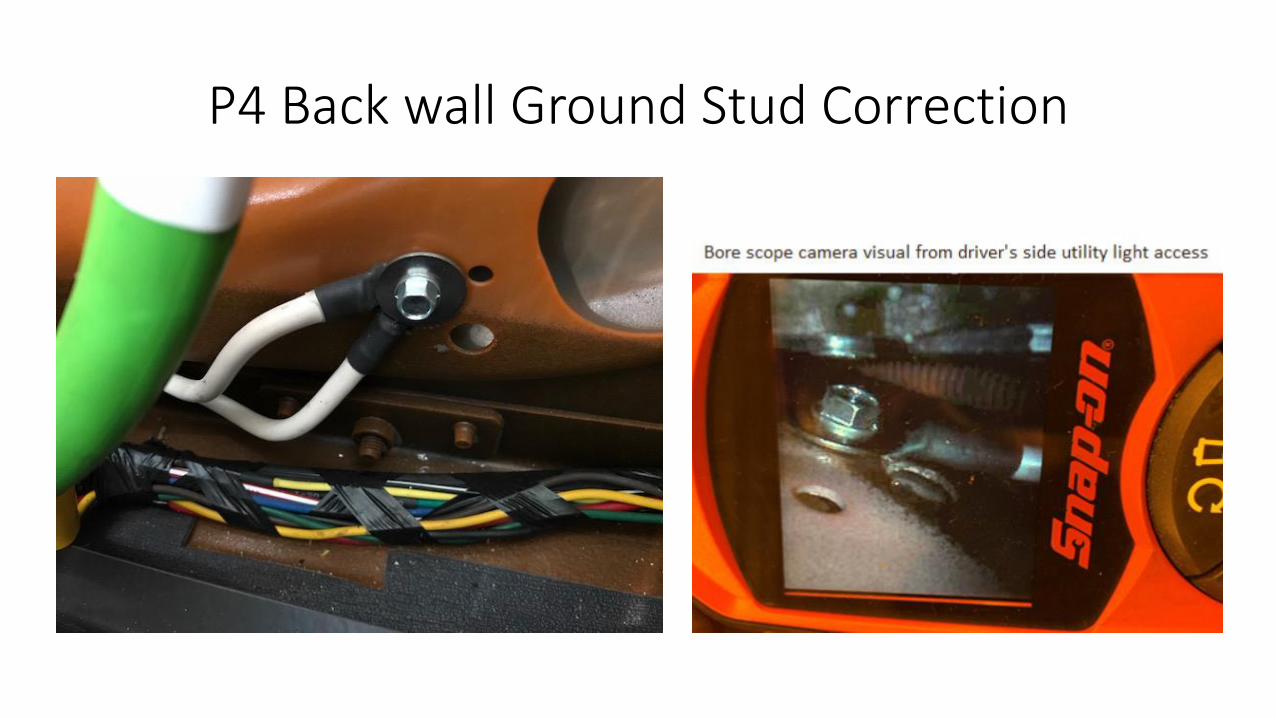
An initial determination of the back wall ground attachment strategy can be quickly determined with the use of a bore scope camera routed
do through the dri er’s side utilit light so ket.

P4 Back wall Ground Stud Correction

P4 Back wall Ground Stud Correction
Note the visuals below for incorrectly installed trailer grounding circuit inside the back of cab regarding datacode 1AZ. Note that there can be
more than (1) eyelet, if the vehicle has an optional connection for trailer ABS only.
P4 Back wall Ground Stud Correction

P4 Back wall Ground Stud Correction
In daycab applications, the back panel can be simply removed.
In sleepercab applications, The corrugated back panel requires excessive effort and downtime for removal.

P4 Back wall Ground Stud Correction
Tools needed:
. ” hole sa½” dri e drill
½” drill itFabricated clinch stud retaining tool
Bore scope camera
Parts needed:
1 QTY 23-13425-022 clinch stud, star washer, and nut
QTY ” X . ” ild steel ar sto k 1 QTY tube sealant

P4 Back wall Ground Stud Correction
Measurements for centering of hole saw in back panel
Vertical/Y location directly off of the floor mat:
. ”Horizontal/X location:
” appro i ate

P4 Back wall Ground Stud Correction

P4 Back wall Ground Stud Correction
Note in the visual below, the parting of the corrugated panel, roughly ” i oard fro the dri ers side he easured fro the door lat h
as noted in previous slide.

P4 Back wall Ground Stud Correction
See below for the drilling function. Set the pilot on the hole saw to a shallow minimal depth. Carefully drill the hole, leave one side of the
drilled portion attached to the panel to act as a hinge for later closure. We are purposely drilling off to the left of the stud location to allow
access for the clinch nut retaining tool in the opening.

P4 Back wall Ground Stud Correction
Remove and discard the improperly installed self tapping screw and washer.
Locate the 2nd hole in the back wall as noted below. Remove the paint directly around where the eyelet(s) will mate with the panel:

P4 Back wall Ground Stud Correction
Fabricate the clinch stud retaining tool to the following dimensions:
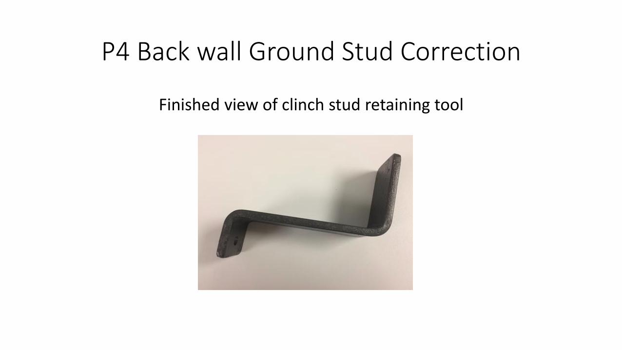
P4 Back wall Ground Stud Correction
Finished view of clinch stud retaining tool

P4 Back wall Ground Stud Correction
Part number 23-13425-022 clinch stud

P4 Back wall Ground Stud Correction
Clinch stud and retaining tool

P4 Back wall Ground Stud Correction
Install clinch stud part number 23-13425-022 into the freshly drilled out ½”+ hole and hold in place with the fabricated clinch nut tool. Note
the following slide that the tool is not bent at 90 degree angles since there is no back panel in this mock up sample. In our example, the tool
ust ha e a degree e d to lear the . ” drilled hole.

P4 Back wall Ground Stud Correction
I stall a ut a d asher o the li h stud. Usi g a / ” i pa t gu , tighten and secure the clinch stud, then remove the nut, washer, and
retaining tool.

P4 Back wall Ground Stud Correction
Install ground cable onto newly installed clinch stud. As noted earlier, there may be (2) cables if the vehicle has an additional trailer ABS
power cord.

P4 Back wall Ground Stud Correction