bacne t foundations june 2012
TRANSCRIPT

IN THIS ISSUEBest Practice for MS/TP WiringThe BACnet Device IDMore BACnet Object Types?Introduction to the BACnet Discovery Tool
Foundations is an educational resource produced by BACnet International for BACnet International members. BACnet International is the cornerstone of your success, and Foundations builds from that cornerstone by providing the ground level knowledge in connecting the dots in building automation.
Foundations is written by volunteers from the BACnet community for integrators/installers/appliers and specifiers/consultants. It complements the BACnet International Journal and the monthly newsletter Cornerstones. For more information on BACnet International, please visit www.bacnetinternational.org.
Questions or article submissions may be directed to [email protected].
June 2012
FOUNDATIONSA BACn e t IN TE R N AT I O N AL P UBL ICAT ION

Some BACnet devices include two sets of screw terminals, one for incoming and one for outgoing wires. But usually there is a single pair so the daisy chain must be created by twisting incoming and outgoing wire ends rattail fashion and capturing the twist in the corresponding screw terminal for the network. Be sure not to expose too much bare twisted wire so that adjacent wires don’t short, or use crimp sleeves.
The shield wire should enter the wire cabinet and shields should also be daisy-chained together and then taped or covered. In some cases devices have “empty” screw terminals where shields can be landed. It is VERY IMPORTANT to assure that shields are connected to ground at only one location along the bus! Typically MS/TP networks will have a single router or large controller in addition to many small devices. It can be convenient to use the router/controller as the single grounding point and as an end node at one extreme of the network or the other.
Termination, Loading and BiasingElectrically, MS/TP uses a type of signaling known as EIA-485. With EIA-485, devices use a single twisted pair which carries a differential voltage relative to a shared ground:
Each node uses a transceiver that consists of a differential receiver and differential driver whose legs are connected together on the “plus” and “minus” sides. When the node is “listening” the driver TxEnable is deasserted putting the driver into a high impedance tri-state mode. When the node needs to transmit, the driver
TxEnable is asserted, applying the Tx state to the differential bus. This means that only one driver can be asserted at any time.
Master-Slave/Token-Passing (MS/TP) is a media access (MAC) layer technology defined in the communications standard known as BACnet (ANSI/ASHRAE 135-2010). MS/TP is widely used and deployed all over the world with estimates ranging into the tens of millions of deployed devices. This article will discuss the theory and best practice to use when designing and implementing networks of MS/TP devices. Experience has shown that those who follow these principles will generally have efficient and reliable MS/TP communications. The root cause of communications issues in MS/TP networks can most often be traced to deviations from these recommendations.
What is MS/TP?As a MAC layer, MS/TP provides a means of conveying a message from one device to another. Most of what MS/TP is involves the signaling of 0s and 1s organized into discrete packages called packets or message frames, and the rules that are associated with arbitrating how devices find each other and negotiate to take turns using the communications network. In this article we’ll be primarily concerned with the electrical aspects of this signaling and wiring rules that result in more reliable communication.
MS/TP uses a daisy-chained communications bus. The network itself uses a twisted-pair plus shield type of wire. The pair is like the rails of a ladder with individual devices wired across the rails like rungs. The wires that form the rung are called stubs. For electrical reasons we want to make the lengths of stubs as short as possible. That’s why MS/TP specifies the use of daisy-chain wiring. Daisy-chaining means landing the network wires on screw terminals that are directly part of the device itself.
Best Practice for MS/TP WiringBy David Fisher, President, PolarSoft; Member ASHRAE; BACnet Lecturer;Chair, BACnet International Education Committee

He was a charter voting member of ASHRAE’s Standards Project Committee 135P and has been active in the development of the BACnet standard (ANSI/ASHRAE 135-1995, 2001,
2004, 2008 and 2010) since its inception. He served as a
voting member on the Standing Standards Project Committee-135
until July 2000 where he is still an active participant and
contributing author. He has taught many courses about BACnet,
networking and communications, and direct digital controls,
including ASHRAE PDS and Short Courses. He is chairman of the BACnet International Education Committee and convener for the
MS/TP Working Group.
The opinions expressed here are those of the author and do not
necessarily represent the position of BACnet International, or any of the organizations with which the
author is affiliated.
MS/TP specifies the use of 510Ω resistors for end point biasing.
Unfortunately there is some difference of opinion within the industry regarding whether network biasing is the best approach to use. The standard indicates a strong preference for network biasing, but allows an alternative called local biasing. With local biasing each node has biasing resistors but the values are much larger. The larger values provide less bias so the effect is localized to the node itself, and also less power is required to be sourced by the node’s power supply. MS/TP specifies values of 47KΩ for these types of biasing resistors:
Since the standard allows both types of biasing philosophy there is always the possibility that a given MS/TP segment may include a mixture of types. For network segments containing 32 or fewer nodes that is not a problem. However, when you want to have the same MS/TP segment include more than 32 nodes, the biasing philosophy becomes very important.
The EIA-485 standard models each transceiver as an idealized 12KΩ impedance (load) and specifies that each driver shall be required to source no more than 60mA. This works out to 32 unit loads. A lot has changed since the EIA-485 standard was created and today there are transceivers designed with higher impedance (½, ¼, and even 1/8 load). Under some circumstances we can take advantage of this and have more than 32 devices on a segment.
MS/TP allows the total length of the twisted pair bus to be up to 4000 feet (1200m) using datarates from 9600, 19200, 38400, 57600 or 76800 bps. At 115200 bps the length must be degraded to 3280 feet (1000m).
The standard also requires that both extreme ends of the network bus shall have 120Ω termination resistors across the receiver:
Termination is important over longer distances and higher speeds to eliminate reflections.
When there is an active driver asserted the voltage differential is reliably held in the 0 or 1 state by the driver. However when all drivers are tri-state
(all deasserted) the differential floats at an indeterminate level. This can cause undesirable effects including random transitions that receivers can interpret as valid data bits. To help overcome these effects, BACnet MS/TP specifies the use of active biasing. The extreme end nodes of the network bus are enhanced to include pullup and pulldown biasing resistors. The values chosen for these resistors must be small enough to provide more than 200mV of voltage drop across each receiver, and large enough that they do not exceed the driver’s ability to overcome the bias which would prevent transmitting data:

NoN-isolated poWer
Although the mathematics is somewhat complicated, it boils down to some simple rules.
• If there are any locally biased (47K) nodes on the segment, the segment is limited to 32 or fewer nodes unless repeaters are used.
• If all of the nodes use partial-load transceivers, e.g. all ¼ load, and network biasing is used, then you can extend the total number of nodes based on load. For example all ¼ load transceivers can have up to 128 nodes without repeaters.
Repeaters are special devices that include two or more sets of EIA-485 transceivers. Data incoming to one set causes the other set(s) to retransmit the same data with low latency (delay). Repeaters are bidirectional so there is some logic within them that determines which side is transmitting at any given time and enables/disables the EIA-485 drivers accordingly.
So which philosophy is “better?” Because of the ubiquity of partial-load transceivers, and the generally cost-sensitive nature of MS/TP devices, the BACnet standard leans toward the use of two point network biasing which allows devices to exploit the additional device possibilities without requiring repeaters. On the other hand, advocates of the 47K philosophy argue that their approach is easier to remember and apply because all nodes are the same and repeater cost is only incurred in larger population network segments. They would also argue that repeater cost is similar to the cost of dual end point biasing, if implemented as a separate device accessory. The other camp would argue that a slight increase in power supply capacity would allow any node to fill the role of end point biasing source. Suffice it to say that there is no clear consensus on a best approach even after 15 years as a standard and many millions of installed nodes.
Non-isolated PowerA typical microcomputer-based controller device that implements MS/TP has several important parts. We will greatly oversimplify this view with the block diagram to the right.
The Microcomputer, memory, Input/Output (I/O) and EIA-485 components share access to a power supply circuit that provides appropriate voltage(s) to all of the individual components. Of particular interest is that the ground reference for the entire device is the same as the power supply ground.
This is important to remember because it’s one of the things that make the two-wire EIA-485 concept work. Recall that the differential voltage signal in EIA-485 is referenced to a ground return path. In this case it’s clear that this ground is the same as the power supply ground for the transceiver and also for the whole device.

Isolated PowerClearly it would be desirable to design the EIA-485 circuits in a way that would reduce or eliminate transient intrusion into the sensitive internals of the microcomputer(s) and their memory, I/O and communications components. In some kinds of MS/TP devices, such as variable frequency drives (VFDs), the motor control circuits themselves can be a source for disruptive transients. In those cases it is more than desirable, it’s necessary. This is usually accomplished by isolating the power supply for the EIA-485 components (or disruptive I/O components or both) from the power supply used for other internals. This greatly simplified diagram shows how this works:
The EIA-485 components (and in some cases also I/O components) instead of being directly coupled to the microcomputer, are connected using optical isolators which convert electrical signals to pulses of light and back to electrical signals again within the isolation chip itself. There is a second power supply that uses its own transformer isolation to provide power for the isolated side of the circuit. Note that the ground for the isolated side is not connected to the non-isolated side and is brought out to its own terminal.
Because isolated EIA-485 power has its own ground, electrical transients that may be induced onto this ground do not affect the microcomputer. However introducing an isolated ground creates a new problem.
The EIA-485 standard specifies a wide range of +12 to -7 volts relative to the reference ground. Modern transceivers have protection built-in that shuts down the transceiver if these voltages are exceeded. Many designs use microfuses and extremely fast switching transorbs for protection also. But even with these measures it is still possible to actually damage some transceivers with sufficiently large transients. When there are two or more devices on the same network, both of which use isolated power, if their isolated ground references
Because all of the devices have power supplies that use the same AC power in the same building, they all theoretically share the same Earth ground point where AC power enters the building.
So in effect there is an implicit shared “third wire” in addition to the twisted pair that is common to the MS/TP devices on the same segment:
The good aspect of this is that a third wire isn’t needed because the nodes share this same ground reference. However there are some bad aspects as well.
In a laboratory setting with devices on a test bench, this works great. In a real world situation where the network wiring is pulled through ceilings and placed in close proximity to other electrical devices, particularly magnetic coil devices like fluorescent ballasts, motors and so forth, it is possible and quite common for electrical transient pulses to become inductively coupled onto the network wiring. While
the differential signal measuring is mostly immune to this kind of noise because it tends to be induced equally into both sides of the differential, it can and does affect the ground potential on the power supplies of non-isolated
devices. The net effect is to disturb the ground reference not only for the EIA-485 transceivers but also for the CPU, memory and I/O components in the devices on the network as well. This can have many different side effects ranging from mild to severe, such as causing the CPU to reset unintentionally, interfere with communications and other bad effects. Keep in mind that to a non-isolated device, the whole MS/TP segment is a 4000 foot long antenna for gathering transients.
MS/TP specifies the use of shielded twisted pair wiring. This means that the twisted pair is wrapped with foil or braided copper shielding along its whole length. By connecting the shield at a single ground point, induced transients are mostly reduced and channeled to ground. This helps reduce the effects of transients on the communications signals, but does nothing to prevent ground transient effects.

The BACnet Device ID is a commonly misunderstood term and value by newcomers to BACnet. Its purpose is often misunderstood. This is perhaps because many developers come to BACnet from other protocols which do not have the extra complexity of an address resolution protocol.
The term “Device ID” is short for Device Identifier, and is shorthand for the Instance Number portion of the BACnet Device object Object_Identifier property. The Device ID is a non-volatile value that is chosen and configured by someone at the site where the BACnet product is installed. The Device ID is used for resolution of network layer addresses into application layer addresses, commonly referred to as “binding”.
ObjectsBACnet uses objects to represent physical inputs, outputs, values, and processes. These objects provide a framework for BACnet messages to access and manipulate the properties of these objects. How the objects map to the real values or physical points used in the device is what each vendor gets to choose when they develop a BACnet product. The quantity of each type of
object in a BACnet product is also something that the vendor will choose. The exception for choice in the quantity of objects is the Device object.
Every BACnet device has one, and only one, Device object. However, a gateway device could represent multiple devices by having each device appear as if they were behind a virtual router.
are not tied together then it is possible for the two “floating” references to be at different levels, thus their combined voltage range can easily push outside of the design spec during transients. As a result, the 135-2010 BACnet standard introduced new guidelines governing best practice for MS/TP. Under the new standard, it is strongly recommended that isolated devices have their isolated ground references tied together through a third wire.
Although it is possible to do this with a separate wire, the best practice is to use (or retrofit with)
shielded twisted triple which is also called 1.5 pair. When daisy-chaining the segment into a device cabinet, the common wire is landed on each isolated ground terminal. The drain daisy-chains through cabinets but is only grounded at one point.
Mixed NetworksSometimes it is necessary or desirable to have a mixed network that incorporates some number of non-isolated MS/TP devices and some number of isolated ones. The issue is how to reconcile the ground reference used by the isolated devices (through the third common wire) and the implied
Earth ground used by the non-isolated devices. The answer is that the common third wire is tied to the Earth ground through a current-limiting 100Ω resistor.
SummaryMS/TP can provide low cost reliable operation under a wide range of conditions. However, careful planning for new construction and diligent research when retrofitting existing networks is essential to reap to benefits that MS/TP has to offer. Biasing, loading and wiring become particularly important in any mixed device network segment. Failure to take these factors into account is the number one cause of field issues with MS/TP, and also the easiest to prevent using best practices.
The BACnet Device IDSteve Karg, Senior Engineer, Watt Stopper
Device ID ValueThe BACnet standard tells us that “each object within a single BACnet Device shall have a unique value for the Object_Identifier property.” It also says “...the system-wide unique Object_Identifier of the BACnet Device...”. The standard specifies that the instance number range is 22-bits: 0-4194303. It also states that “No object shall have an Object_Identifier with an instance number of 4194303.”
The only method to make a system-wide unique Device ID from 0 to 4194302 is to have this value configurable at the building site where the BACnet product is installed. This can be accomplished in a variety of ways, from a user interface on the product to simply allowing the Device object Object_Identifier property to be writable using the BACnet WriteProperty service. This Device ID, which must be unique system wide, provides a mechanism for referencing every Device in the control system network.
Device Address BindingBut why do we even need a Device ID when each device has a MAC (Media Access Control) address? An Ethernet MAC address is large (6 bytes) enough to be unique across a large building network, but an MS/TP MAC address is too small to be used in any building that requires more than 127 devices. BACnet devices can use a variety of datalink and physical layer interfaces, and utilize a BACnet router to pass messages between the interfaces. The router (network layer) must also be accounted for when communicating between BACnet devices located on different interfaces.
BACnet uses a type of address resolution protocol based on a Device ID query broadcast (Who-Is service) to the network to find a specific device. The device reply (I-Am) will contain information about the route and include the MAC address. Having an address resolution protocol is useful if a device fails and is replaced as it can simply be re-numbered to the failed Device ID. It is also useful in systems where the MAC address may change (i.e. BACnet/IP and DHCP service). The address resolution protocol is needed when routers are utilized in the network to join various datalink and physical network segments.
After discovery, the Device ID can now be associated with this MAC address and route. This data will be used as the unicast address in the majority of BACnet messages, including ReadProperty, WriteProperty, and DeviceCommunicationControl, that are directed to that Device ID.
PropertiesEach BACnet object contains a number of properties. Some of the properties are required to exist in the object, such as Object_Identifier, Object_Name, and Object_Type properties. Some properties are optional and may be supported by the vendor if that device needs that property, or if the vendor chooses to implement a feature that mandates that an optional property be supported by that object. Some properties are proprietary, or non-standard. A proprietary property is often a property that is needed by the vendor for specific object functionality, but is not defined by the standard set of properties for that object in the BACnet standard. Some properties are read-only. Some properties are writable.
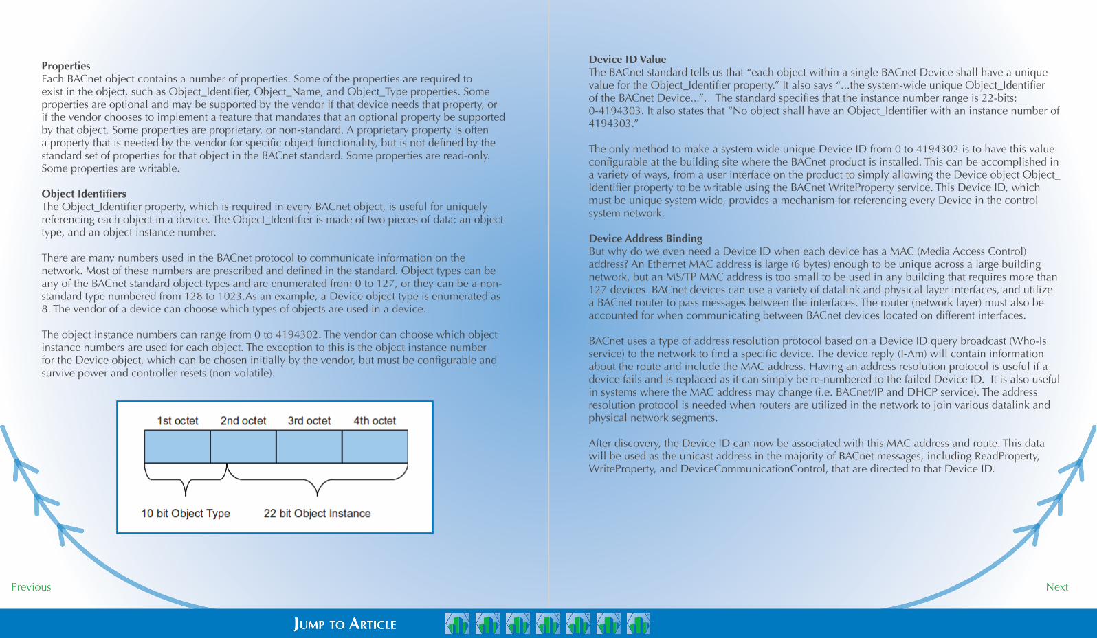
Object IdentifiersThe Object_Identifier property, which is required in every BACnet object, is useful for uniquely referencing each object in a device. The Object_Identifier is made of two pieces of data: an object type, and an object instance number.
There are many numbers used in the BACnet protocol to communicate information on the network. Most of these numbers are prescribed and defined in the standard. Object types can be any of the BACnet standard object types and are enumerated from 0 to 127, or they can be a non-standard type numbered from 128 to 1023.As an example, a Device object type is enumerated as 8. The vendor of a device can choose which types of objects are used in a device.
The object instance numbers can range from 0 to 4194302. The vendor can choose which object instance numbers are used for each object. The exception to this is the object instance number for the Device object, which can be chosen initially by the vendor, but must be configurable and survive power and controller resets (non-volatile).
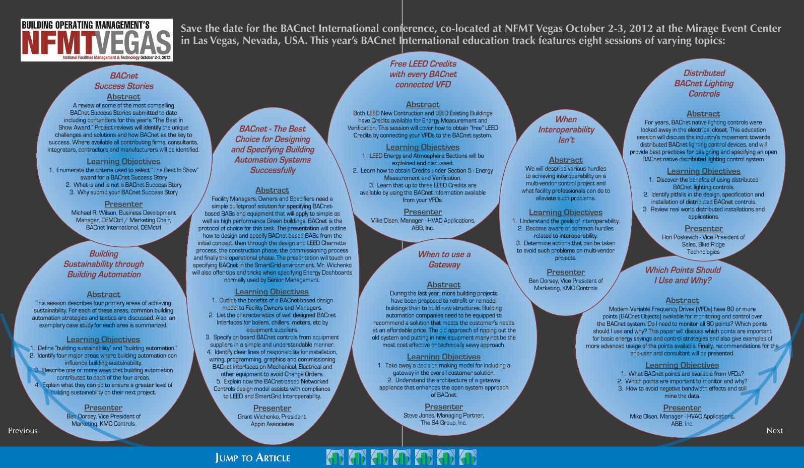
Free LEED Credits with every BACnet
connected VFD
AbstractBoth LEED New Contruction and LEED Existing Buildings
have Credits available for Energy Measurement and Verification. This session will cover how to obtain “free” LEED
Credits by connecting your VFDs to the BACnet system.
Learning Objectives1. LEED Energy and Atmosphere Sections will be
explained and discussed.2. Learn how to obtain Credits under Section 5 - Energy
Measurement and Verification.3. Learn that up to three LEED Credits are
available by using the BACnet information available from your VFDs.
PresenterMike Olsen, Manager - HVAC Applications,
ABB, Inc.
Save the date for the BACnet International conference, co-located at NFMT Vegas October 2-3, 2012 at the Mirage Event Center in Las Vegas, Nevada, USA. This year’s BACnet International education track features eight sessions of varying topics:
Building Sustainability through Building Automation
AbstractThis session describes four primary areas of achieving
sustainability. For each of these areas, common building automation strategies and tactics are discussed. Also, an
exemplary case study for each area is summarized.
Learning Objectives1. Define “building sustainability” and “building automation.”2. Identify four major areas where building automation can
influence building sustainability.3. Describe one or more ways that building automation
contributes to each of the four areas.4. Explain what they can do to ensure a greater level of
building sustainability on their next project.
PresenterBen Dorsey, Vice President of
Marketing, KMC Controls
When to use a Gateway
AbstractDuring the last year, more building projects have been proposed to retrofit or remodel
buildings than to build new structures. Building automation companies need to be equipped to
recommend a solution that meets the customer’s needs at an affordable price. The old approach of ripping out the old system and putting in new equipment many not be the
most cost effective or technically savvy approach.
Learning Objectives1. Take away a decision making model for including a
gateway in the overall customer solution.2. Understand the architecture of a gateway
appliance that enhances the open system approach of BACnet.
PresenterSteve Jones, Managing Partner,
The S4 Group, Inc.
Which Points Should I Use and Why?
AbstractModern Variable Frequency Drives (VFDs) have 80 or more
points (BACnet Objects) available for monitoring and control over the BACnet system. Do I need to monitor all 80 points? Which points
should I use and why? This paper will discuss which points are important for basic energy savings and control strategies and also give examples of
more advanced usage of the points available. Finally, recommendations for the end-user and consultant will be presented.
Learning Objectives1. What BACnet points are available from VFDs?
2. Which points are important to monitor and why?3. How to avoid negative bandwidth effects and still
mine the data.
PresenterMike Olsen, Manager - HVAC Applications,
ABB, Inc.
BACnet - The Best Choice for Designing
and Specifying Building Automation Systems
Successfully
AbstractFacility Managers, Owners and Specifiers need a simple bulletproof solution for specifying BACnet-
based BASs and equipment that will apply to simple as well as high performance Green buildings. BACnet is the
protocol of choice for this task. The presentation will outline how to design and specify BACnet-based BASs from the
initial concept, then through the design and LEED Charrette process, the construction phase, the commissioning process
and finally the operational phase. The presentation will touch on specifying BACnet in the SmartGrid environment. Mr. Wichenko will also offer tips and tricks when specifying Energy Dashboards
normally used by Senior Management.
Learning Objectives1. Outline the benefits of a BACnet-based design
model to Facility Owners and Managers.2. List the characteristics of well designed BACnet
Interfaces for boilers, chillers, meters, etc byequipment suppliers.
3. Specify on board BACnet controls from equipment suppliers in a simple and understandable manner.
4. Identify clear lines of responsibility for installation, wiring, programming, graphics and commissioning
BACnet interfaces on Mechanical, Electrical and other equipment to avoid Change Orders.
5. Explain how the BACnet-based Networked Controls design model assists with compliance
to LEED and SmartGrid Interoperability.
PresenterGrant Wichenko, President,
Appin Associates
Distributed BACnet Lighting
Controls
AbstractFor years, BACnet native lighting controls were
locked away in the electrical closet. This education session will discuss the industry’s movement towards
distributed BACnet lighting control devices, and will provide best practices for designing and specifying an open
BACnet native distributed lighting control system.
Learning Objectives1. Discover the benefits of using distributed
BACnet lighting controls.2. Identify pitfalls in the design, specification and
installation of distributed BACnet controls.3. Review real world distributed installations and
applications.
PresenterRon Poskevich - Vice President of
Sales, Blue RidgeTechnologies
WhenInteroperability
Isn’t
AbstractWe will describe various hurdles to achieving interoperability on a multi-vendor control project and
what facility professionals can do to alleviate such problems.
Learning Objectives1. Understand the goals of interoperability.
2. Become aware of common hurdles related to interoperability.
3. Determine actions that can be taken to avoid such problems on multi-vendor
projects.
PresenterBen Dorsey, Vice President of
Marketing, KMC Controls
BACnet Success Stories
AbstractA review of some of the most compelling
BACnet Success Stories submitted to date including contenders for this year’s “The Best in
Show Award.” Project reviews will identify the unique challenges and solutions and how BACnet as the key to
success. Where available all contributing firms, consultants, integrators, contractors and manufacturers will be identified.
Learning Objectives1. Enumerate the criteria used to select “The Best In Show”
award for a BACnet Success Story2. What is and is not a BACnet Success Story
3. Why submit your BACnet Success Story
PresenterMichael R. Wilson, Business Development
Manager, OEMCtrl / Marketing Chair, BACnet International, OEMctrl
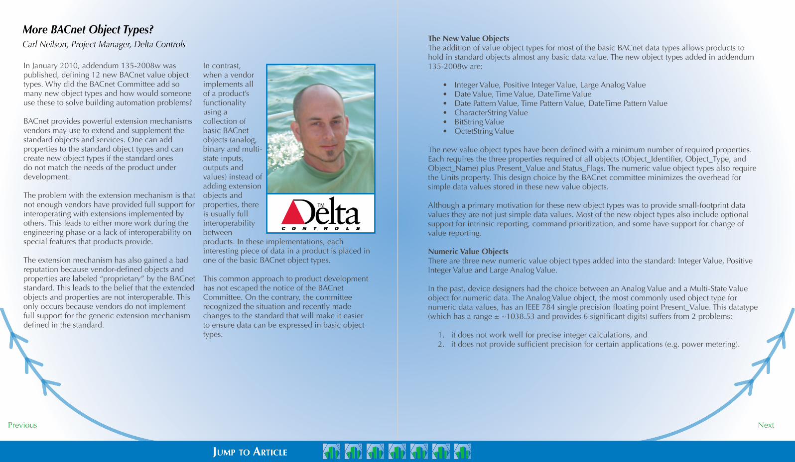
In January 2010, addendum 135-2008w was published, defining 12 new BACnet value object types. Why did the BACnet Committee add so many new object types and how would someone use these to solve building automation problems?
BACnet provides powerful extension mechanisms vendors may use to extend and supplement the standard objects and services. One can add properties to the standard object types and can create new object types if the standard ones do not match the needs of the product under development.
The problem with the extension mechanism is that not enough vendors have provided full support for interoperating with extensions implemented by others. This leads to either more work during the engineering phase or a lack of interoperability on special features that products provide.
The extension mechanism has also gained a bad reputation because vendor-defined objects and properties are labeled “proprietary” by the BACnet standard. This leads to the belief that the extended objects and properties are not interoperable. This only occurs because vendors do not implement full support for the generic extension mechanism defined in the standard.
In contrast, when a vendor implements all of a product’s functionality using a collection of basic BACnet objects (analog, binary and multi-state inputs, outputs and values) instead of adding extension objects and properties, there is usually full interoperability between products. In these implementations, each interesting piece of data in a product is placed in one of the basic BACnet object types.
This common approach to product development has not escaped the notice of the BACnet Committee. On the contrary, the committee recognized the situation and recently made changes to the standard that will make it easier to ensure data can be expressed in basic object types.
The New Value ObjectsThe addition of value object types for most of the basic BACnet data types allows products to hold in standard objects almost any basic data value. The new object types added in addendum 135-2008w are:
• Integer Value, Positive Integer Value, Large Analog Value• Date Value, Time Value, DateTime Value• Date Pattern Value, Time Pattern Value, DateTime Pattern Value • CharacterString Value• BitString Value• OctetString Value
The new value object types have been defined with a minimum number of required properties. Each requires the three properties required of all objects (Object_Identifier, Object_Type, and Object_Name) plus Present_Value and Status_Flags. The numeric value object types also require the Units property. This design choice by the BACnet committee minimizes the overhead for simple data values stored in these new value objects.
Although a primary motivation for these new object types was to provide small-footprint data values they are not just simple data values. Most of the new object types also include optional support for intrinsic reporting, command prioritization, and some have support for change of value reporting.
Numeric Value ObjectsThere are three new numeric value object types added into the standard: Integer Value, Positive Integer Value and Large Analog Value.
In the past, device designers had the choice between an Analog Value and a Multi-State Value object for numeric data. The Analog Value object, the most commonly used object type for numeric data values, has an IEEE 784 single precision floating point Present_Value. This datatype (which has a range ± ~1038.53 and provides 6 significant digits) suffers from 2 problems:
1. it does not work well for precise integer calculations, and2. it does not provide sufficient precision for certain applications (e.g. power metering).
More BACnet Object Types?Carl Neilson, Project Manager, Delta Controls

The Multi-State object type, while intended for modeling discrete states, can be used to represent positive integer values but there are 2 significant issues with using it for a generic integer data type. The Multi-State Value object cannot hold the value 0, and it is required to have a character string description for each of its – potentially many – values. The new Integer Value and Positive Integer Value object types allow for proper representation of integer data values. They do not suffer from the calculation issues of the Analog Value object, nor do they suffer either of the problems noted with Multi-State Value objects. While the new integer value types theoretically have an unbounded value range, BACnet devices commonly limit internal integer and positive integer values to 32 bits which provide the ranges shown in Range A below.
The new Large Analog Value object type provides better value range and precision that the existing Analog Value object type. The ranges and precisions of the two analog value object types are shown below in Range B. This greater range and greater accuracy will be useful in many applications.
Date and Time ObjectsThe new date and time object types come in two main classes: specific date / time values and date / time patterns.
The pattern values differ from the specific date / time value in that they can contain unspecified values. Unspecified values available in BACnet date and times are listed in the chart to the right.
The pattern values allow the specification of a recurring date or time. Significantly simpler than a Schedule object a device might use these date / time pattern objects for indicating simple scheduling (that relies on a single rule instead of the set of complex rules contained in a Schedule object).
The non-pattern date / time objects will be useful for devices that need to record when an action is going to occur. If the time that an action is to be executed is not governed by a schedule but rather by a calculation, these objects provide an excellent location for indicating when the action is expected to next occur. For example, a device might use a DateTime Value object to indicate the next transition to or from daylight savings time.
Range A:Integer Value -2147483648 .. 2147483647Positive Integer Value 0 .. 4294967295Analog Value -999999 .. 999999 (accurate integer range)
Range B:Analog Value ± ~1038.53 with 6 significant digitsLarge Analog Value ± ~10308.3 with 15 significant digits
CharacterString ObjectBefore the addition of the new object types, if a product needed a string value and the product was restricted to using standard properties, the only choice the product had for character string values was to use a standard property, such as Description, outside of its intended purpose.The new character string object type solves this problem. Some expected use cases for the CharacterString object type are: provide access to the text for small displays and annunciator panels; provide textual diagnostic data.
BitString ObjectThe BitString Value allows a device to have a related set of Boolean values. The Present_Value of the object contains multiple Boolean values that are read and written together. The same information could be modeled with multiple Binary Value objects. A product designer will need to choose which is better for their use case, a set of Binary Values allowing each to be independently written to, or a BitString Value which provides a more compact representation and indicates some form of logical relationship between the values.
UNspecified date/time ValUes
Unspecified Date Values
unspecified
even months
odd months
last day of the month
even days
odd days
Unspecified Time Values
unspecified
Can be used in any of the date fields and
is used to match to any valid value.
Matches to even months (February, April,
etc.)
Matches to odd months (January, March,
etc.)
Matches the last day of the month.
Matches even days of the month.
Matches odd days of the month.
Can be used in any of the time fields and
is used to match to any valid value.

OctetString ObjectThe OctetString Value will mostly likely be the least used of the new object types as the data value of the object will not be as easily understood as that of other types. Given that the data value is an arbitrary sequence of bytes, the value of the object will remain somewhat proprietary. While they can be used interoperably for control, it is more likely that these will be used for diagnostic purposes showing the detail of internal items within a controller or providing a raw configuration item. For example, a BACnet gateway might provide an OctetString Value object for displaying the content of recently sent or received messages on the “other side” of the gateway.
Looking ForwardAs mentioned previously, interoperability is more commonly achieved when a collection of basic objects is used in place of a complex proprietary object. The downside is that the relationships between the data values can be lost when an object is broken up into its constituent parts.
To solve the logical grouping problem, the Structured View object can be used. Instead of implementing a proprietary object type, basic BACnet object types are used, one for each data value, and the Structured View object is used to collect all of the data values together into a single grouping.
The BACnet Committee is looking to the Structured View object to perform this function in a standard way in the future. The committee is actively developing a process whereby standard models can be developed and implemented using the Structured View object. The concept is to allow faster development of standardized “objects” by those industry groups that are best placed to develop those objects (e.g. Smart Grid experts would develop the standardized models for the Smart Grid objects). Instead of implementing the models as new BACnet objects, the models would be implemented using Structured View objects.
The benefit of this approach is twofold:• those devices that understand the
Structured View based model can determine the semantics of individual basic BACnet objects, and
• those devices that do not have knowledge of the models can still easily consume the data because the data values reside in known object types (basic value objects).
As of this writing (April 2012), the BACnet Committee’s proposed direction for modeling standard complex systems is in an Advisory Public Review. The feedback from the public will drive the ultimate direction that the BACnet standard takes. Regardless, these new objects are in the standard and are available for product designers to use to design better solutions to the problems found in building automation.
(Large Analog Value, 1)
47844kW
Object_Iden�fierObject_Name Current Demand LevelPresent_Value
Units
ValueProperty
(Posive Integer Value, 1)
4327890no-units
Object_IdenfierObject_Name kW Pulse CountPresent_Value
Units
ValueProperty
(Analog Value, 1)Object_Iden�fierObject_NamePresent_Value
Units
ValueProperty
kW Daily Peak59877
kW
Object_Iden�fierObject_NamePresent_Value
Units
ValueProperty(Analog Value, 2)kW Monthly Peak
59877kW
Object_Iden�fierObject_NamePresent_Value
Units
ValueProperty(Analog Value, 3)
kW
kW Yearly Peak92302
Object_Iden�fierObject_NamePresent_Value
Units
ValueProperty(Large Analog Value, 2)
kWh291000
kWh Today
Object_Iden�fierObject_NamePresent_Value
Units
ValueProperty(Large Analog Value, 3)
kWh
kWh Month To Date13002390
Object_Iden�fierObject_NamePresent_Value
Units
ValueProperty(Large Analog Value, 4)
kWh
kWh Year To Date5250469131
ValueProperty(Structured View, 1)Object_Idenfier
Object_Name Meter 1EquipmentNode_Type
“Electrical Meter”Node_Subtype(Posive Integer Value, 1)Subordinate_List[1]
(Large Analog Value, 1)Subordinate_List[2](Analog Value, 1)Subordinate_List[3](Analog Value, 2)Subordinate_List[4](Analog Value, 3)Subordinate_List[5]
(Large Analog Value, 1)Subordinate_List[6](Large Analog Value, 2)Subordinate_List[6](Large Analog Value, 3)Subordinate_List[6]
The property IDs used in this object would not be known by other devices, nor would the ”name” of the data values..
4327890
5987759877
512 (kW Pulse Count)514 (Current Demand Level) 47844
515 (kW Daily Peak)516 (kW Monthly Peak)
92302517 (kW Yearly Peak)291000518 (kWh Today)
13002390519 (kWh Month To Date)5250469131520 (kWh Year To Date)
ValueProperty(128, 1)Object_Iden�fierMeter 1Object_Name
comparisoN of a proprietary exteNsioN object VersUs strUctUred VieW aNd basic objects

Contemporary Controls has developed a vendor-neutral BACnet Discovery Tool (BDT) to determine if a BACnet router is successfully communicating to attached devices. As part of Contemporary Controls’ ongoing mission to simplify the use of BACnet, the BDT is available as a free download from the Contemporary Controls website.
BDT is a BACnet/IP application for Windows® that is easy to install and use. It is an excellent means for discovering and verifying communication with MS/TP devices that are being accessed through BACnet/IP routers such as those available from Contemporary Controls: the BASRT-B DIN-rail mounted BACnet/IP-to-MS/TP router — or its portable counterpart, the BASRTP-B. At Contemporary Controls, we use BDT with equipment from different BACnet vendors to prove our routers operate with different equipment configurations.
BDT has proved to be very popular — as one satisfied user reports:
BDT 2.03 has become one of the BACnet applications I have begun to rely on when discovering BACnet devices and objects. For a quick snapshot of networks and the MAC addresses of the controllers on them is as easy as one click, and the support of BBMD to connect to remote sites is a great feature. The ability to scan the present values of all supported BACnet objects in discovered devices as well as the ability to write to the present value (at selectable priority levels) of certain objects make BDT 2.03 one of the most feature rich freely down-loadable BACnet applications on the web.
After downloading BDT from Contemporary Controls, unzip its file set to any location on your host PC hard drive (be sure to keep all the files together at the chosen location). The file set will include an instruction sheet in PDF format and the following four files:
• bacnet-stack.dll • BDT 2.03.00.exe• mfc71d.dll• msvcr71d.dll
If you are not using Windows 7, double-click on the BDT2.03.00.exe file to launch BDT. But if you are using Windows 7, right click the file name, choose to “Run as Administrator” and click “Yes” in the dialog that appears — otherwise, BDT will not function properly.
When you attempt to open BDT, Windows may warn you that the file has no valid digital signature. It is safe to ignore this warning and proceed.
Before initiating any BDT activity, you should determine the scope of what you wish to accomplish. The first thing to consider is whether or not your BACnet internetwork crosses IP subnets — and is therefore using a BACnet/IP Broadcast Management Device (BBMD). If a BBMD is present, you may wish to use it to examine more of the BACnet internetwork than just your local subnet. You can do this by using the BDT’s Foreign Device
Registration (FDR) function to register the BDT application as a Foreign Device with a BBMD in a remote subnet.
Setting the BBMD, if needed. In the BBMD Address field, enter the IP address of the BBMD with which you wish to register. (You do not specify a subnet mask — this is determined by other equipment in the network.) In some larger networks with several subnets, there may be multiple BBMDs. In such cases, you would normally register with the central BBMD and thus access the entire BACnet internetwork. You could perform FDR with a non-central BBMD on a specific subnet, but you may not know the extent to which the various BBMDs are sharing information — and you might not access the devices that you need to contact. Targeting the central BBMD is almost always the best option. When you click on the Set BBMD button, registration is completed.
Using the Search function. After setting theBBMD (if needed) and with your host PC attached to the network of interest, click the Search button — not the Scan button, which should only be used after a search has built a database of objects. As the Search function runs, it transmits BACnet Who-Is messages and a progress bar appears. NOTE: BDT sends a BACnet/IP Who-Is — not a BACnet/Ethernet Who-Is — so it will not discover devices that only support BACnet/Ethernet.
When BDT has completed its search, the progress bar will disappear, the discovered BACnet devices will be listed in the main window and the number of discovered devices will be reported in the Devices Discovered field.
Each I-Am response identifies the• the Device Instance number of the
responding device• the Device Name of the device• the IP Address and UDP Port number
through which the device was contacted• and (for MS/TP master devices) the MS/TP
Network number and MS/TP MAC Address
Each piece of equipment producing an I-Am response could be simply a BACnet/IP device — or it could be a BACnet/IP to BACnet MS/TP router acting as an intermediary for devices on the MS/TP side. If the reported Device Instance is that of an MS/TP device, then the MS/TP Network and MAC information will complete the line.
To investigate the objects contained by any discovered device, double-click that device’s line in the discovered device list. A new window will appear (the pop-up in Figure 1 below) and display a list of the discovered objects within the selected device. Also, the number of discovered objects will be reported in the Objects field. BDT can support up to 1000 devices and each device can have up to 2000 objects.
Introduction to the BACnet Discovery ToolDiscover and Verify Communication with MS/TP Devicesby Bill Greer, Contemporary Controls
fiGUre 1: discoVered objects list

Executing the Search function creates an object database that is used by the Scan function. Clicking the Scan button opens a window where you will see a bar indicating the progress in Building Object — that is, creating a scan list of objects extracted from the object database. As the list is built, the current Device and its Object are identified in their respective fields.
After the scan object list has been built, the scan proceeds as shown in Figure 3. As the list is scanned, the current Device and its Object being scanned are identified in their respective fields. If an object fails to report its data, BDT retries the data acquisition four times before registering an error and moving on to the next object. These two fields — Errors and Retries — are incremented without reset for as long as the scan proceeds. You can also Pause the scan, if needed.
When scanning for present-values, BDT will display the currently read values. When all objects have been read, BDT will start displaying again — at the first line. Because present-values will appear in the same place in the display, current values can be viewed
by scrolling the list up or down. If a present-value cannot be read, an error statement will occupy a line in the list.
When you are finished with scanning, click the OK button to terminate the scan. When you are finished with the BDT, close all of its windows.
To download BDT, go to www.ccontrols.com/bdt.
You can double-click the device object line to examine the Device Object Properties which brings up an window. As shown, this window reports many helpful Device Object Properties (Device 2749211 in our example in figure 2).
If you close the above window and again display the list of objects contained by the device, you can double-click one of its objects to bring up an Object Properties window.
The Object Properties window displays read-only values — Object Name, its Present Value and four on/off status reports (checked means on) — and two writeable elements lower down which, although always visible, only yield results for output objects.
If the Write button is not dimmed, the examined object is writeable — in which case, you can enter a number in the Write Value box, set a Priority value and click the Write button to apply your changes. Set a priority value by clicking the Priority field then adjusting the level displayed below the field by scrolling through the available levels using either your keyboard up/down arrow keys or the miniature up/down scroll controls. Clicking
the Refresh button on the right will reacquire and redisplay the read-only information.
After you are done with the Object Properties window, you can close it with either the OK or Cancel button. Then you can double-click another object to view and/or adjust its properties.
Only click the Scan button after the Search function has been run. Usually you should avoid the Scan function because it often creates more network activity than desired by continuously reading the Present Value of most objects that have this property (and alert you if an attempt fails). However, when commissioning or troubleshooting a network, the Scan function can usefully confirm that all devices and objects are properly installed, working and updating — this could be especially helpful if you do not have a building controller at your disposal to check this for you. NOTE: The Scan function only stops when you close the Scan window. Leaving it running can consume significant network bandwidth — and if a building controller is running, communication errors could result.
fiGUre 2: deVice object propertiesfiGUre 3: Scan fUNctioN

Building Better with
© BACnet International 2012 – further editorial use of articles in Foundations is encouraged. Please send a copy to the BACnet International office [email protected].
© BACnet is a registered trademark of the American Society of Heating, Refrigerating and Air Conditioning Engineers, Inc. (ASHRAE).
DISCLAIMER OF ENDORSEMENT:
Foundations is a publication which is as designed to be as inclusive as possible in
sharing of views and information. As such, there may be references to resources,
products, companies or services that have not been vetted or endorsed by
BACnet International. BACnet International provides these resources solely for
your information. Responsibility for accuracy lies ultimately with the individual
authors.
Special Thanks:
Foundations is a project of the BACnet International Education
Committee, and would not be publishable without those volunteers’
time and talents.
Additionally, Foundations is supported by the BACnet International
Board of Directors:
Andy McMillan, Philips Teletrol
Brad Hill, Honeywell International
Paul Jordan, American Auto-Matrix
Roland Laird, Reliable Controls
Raymond Rae, Delta Controls, Inc.
Dave Robin, Automated Logic
Nancy Stein, Siemens Industry, Inc.
A special thank you to all volunteers in the BACnet community.
BACnet International Executive Office
PMB 321 • 2900 Delk Rd, Suite 700 • Marietta, GA 30067-5350
770-971-6003 (ph) • 678-229-2777 (fax)
www.bacnetinternational.org • [email protected]