bacteria removal filter new - smc
TRANSCRIPT

Hollow Fiber Element
0.01 μmFiltering effi ciency 99.99 %
Nominal fi ltration rating
0.03 MPaInlet pressure 0.7 MPa,
at max. fl ow rate
1.0 MPaAt 20 °C
500L/min (ANR)
Initial pressure drop
Max. operating pressure
Flow rate
¡ Use of FDA/Food Sanitation Law compliant
materials∗2
¡Use of NSF-H1 grade lubrication for fl ow path
∗2 Parts in contact with fl uid: Resin/Rubber
Designed for use in applications to HACCP principles and FSSC22000 standards
Captures bacteria in the compressed air
∗1 LRV (Log Reduction Value): A mathematical representation of bacteria capture performance of filter element
∗1
Applications
¡ Blows air for opening packaging bags
¡ Blows air to ice cream lids and cups
¡ Fills rice bags with nitrogen (to prevent oxidation)
Bacteria Removal Filter
SFDA SeriesCAT.EUS120-7A-UK
RoHS
NewNew

How to Order
Specifi cations
∗1 Maximum fl ow rate at inlet pressure 0.7 MPa and pressure drop 0.03 MPa
∗2 Measured under SMC’s specifi ed conditions
∗3 The maximum operating pressure varies depending on temperature. Refer to the graph that
shows the relationship between the operating temperature and maximum operating pressure
on the left.
∗4 This means that the element does not break at 0.5 MPa. See “Specifi c Product Precautions.”
∗5 The bacteria removal fi lter is intended to fi lter solid particles. It is not suitable for the separation
of water and oil.
Relationship between
Operating Temperature and
Max. Operating Pressure
RoHS
0 10 20 30 40 50
Operating temperature [°C]
Max. opera
ting p
ressure
[M
Pa]
1.2
1.0
0.8
0.6
0.4
0.2
0
Model SFDA203
Port size Rc1/4, NPT1/4, G1/4, Rc3/8, NPT3/8, G3/8
Fluid Air (Nitrogen)
Rated flow 500 L/min (ANR)∗1
Nominal fi ltration rating∗2 0.01 μm (99.99 %)∗5
Operating pressure range∗3 −100 kPa to 1.0 MPa (For nitrogen: 0.99 MPa)
Operating temperature 5 to 45 °C
Initial pressure drop 0.03 MPa (Inlet pressure 0.7 MPa, at max. fl ow rate)
Element proof differential pressure∗4 0.5 MPa
Proof pressure 1.5 MPa
Element life 1 year, or when the pressure drop reaches 0.1 MPa
Materials of
parts in contact
with fluid
Metal parts Stainless steel
Resin/Rubber parts Materials compliant with FDA/Food Sanitation Law
Lubrication oil NSF-H1 grade
WeightPort size 1/4 450 g
Port size 3/8 430 g
Bacteria Removal Filter Hollow Fiber Element
SFDA Series
SFDA 2 0 3 02
Size
Symbol Max. fl ow rate
2 500 L/min
Case material
Symbol Case material
3 Stainless steel
Thread type
Symbol Type
Nil Rc
F G
N NPT
Port size
Symbol Size
02 1/4
03 3/8
∗ The bracket is equipped as standard.
(Single unit: SFD-BR200)
Bacteria Removal Filter(Bacteria removal performance LRV ≥ 9)
2
Bacteria removal performance (bacteria capture performance of fi lter element) LRV ≥ 9
For example, this value indicates that 4 billion pieces of bacteria are reduced to 0 after passing through the fi lter.
Refer to the equation below for details.
LRV (Log Reduction Value) indicates the bacteria capture performance.
LRV = Log10A: 4.7 x 109
= 9.7A: Total number of test bacteria applied upstream of the fi lter
B: 1∗1 B: Total number of test bacteria after passing through the fi lter (downstream)
∗1 When the number of bacteria contained in the fi ltrate is 0, substitute 1.
[Demonstrated by a third-party research institution (Test reference report No.: 2019D-BT-548)]
∗ This does not guarantee that all bacteria will be removed. Not for eliminating the virus. This
is the data evaluated based on JIS K 3835.
1

Flow Rate Characteristics
Construction
Dimensions
SFDA203-02 03, -N02
03, -F02 03
Flow rate [L/min (ANR)]
Pre
ssure
dro
p [M
Pa]
0
0.01
0.02
0.03
0.04
0 100 200 300 400 500 600
0.9 MPa
0.1 MPa 0.3 MPa 0.5 MPa 0.7 MPa
Max. flow rate line
SFDA203-02/03
Component Parts Replacement Parts
wq r rte
Description Part no. Set description
Element set SFDA-EL200 ert (With 3 O-rings)
Bracket SFD-BR200 Material: Stainless steel 304
No. Description Material
1 Case Stainless steel
2 Cover Stainless steel
3 Element PC, Polyolefin, PU
4 O-ring FKM
5 O-ring FKM
SFDA203-02/03
ø39
70
80
40
24
108
2 x ø4.525
Bracket
2
Bacteria Removal Filter Hollow Fiber Element SFDA Series

Selection
Warning1. Do not select a model exceeding specifi cation ranges and
carefully consider the purpose of use, required specifi ca-
tions, and operating conditions, such as fl uid, pressure,
fl ow rate, nominal fi ltration rating, and environment.
2. The product is not certifi ed under the High Pressure
Gas Safety law, so for nitrogen, its maximum
operating pressure will be 0.99 MPa (gauge pressure).
3. The product is provided for use in manufacturing indus-
tries. Contact us beforehand if the product will be used
in an application such as a caisson shield, breathing,
food (other than air-blowing), and/or medical treatment
that affects the human body directly or indirectly.
4. The product removes and reduces bacteria contained in
the compressed air. Bacterial removal refers to the effect
of reducing bacteria. It does not mean that all bacteria are
eliminated. Not for eliminating the virus.
LRV (Log Reduction Value) is a mathematical representa-
tion that was obtained from the test (evaluation based on
JIS K 3835) using test bacteria (Brevundimonas diminuta).
5. The product is assembled and packaged in a clean room
environment but does not adhere to the sanitation control
procedures for the use in food and medical industries.
6. If the compressed air includes ozone, do not use it since
it may damage the product or cause malfunction.
Caution on Installation
Caution1. If the pressure difference (pressure drop) between
the inlet and the outlet exceeds 0.1 MPa, it can
cause damage to the product.
2. Do not install the product in a place where it can be
affected by a pulsation (including surge pressure)
of over 0.1 MPa.
3. Use caution regarding the particles that may be
emitted from the outlet side of pneumatic equip-
ment.
The installation of pneumatic equipment on the outlet side can
deteriorate the cleanliness because a particle will be
generated from the equipment.
The mounting position of the pneumatic equipment needs to
be considered.
4. Set the air fl ow capacity with an initial pressure drop
of 0.03 MPa or less. If the initial pressure drop is set
to be high, its life will be shortened due to clogging.
5. Generally, the following pollutant particles are
contained in compressed air.
[Pollutant particle substances contained in the
compressed air]
· Moisture (drainage)
· Dusts and particles which are in the surrounding air
· Deteriorated oil which is discharged from the compressor
· Solid foreign matter such as rust and/or oil in the piping
1) The SFDA series is not compatible with compressed air
which contains fl uids such as water and/or oil.
2) Install a dryer (IDF, IDG, ID series), line fi lter (AFF-D
series), mist separator (AM series), micro mist separator
(AMD series), super mist separator (AME series), or odor
removal fi lter (AMF series), etc., for the source of the air for
the SFDA series.
6. Using with a fl ow-rate much higher than its
specifi cation could lead to exceeding the differential
pressure the product can resist.
Use the product within its specifi cations. Also, take care about
the replacement period of the product, taking into
consideration that the differential pressure of the fi lter will
increase over time.
Mounting
Warning1. Operation manual
Install the products and operate them only after reading the
operation manual carefully and understanding its contents. Also,
keep the manual where it can be referred to as necessary.
2. Flushing
Flush the piping line before using the product for the fi rst time
and after it has been replaced. Also, if piping, etc., is to be
connected, fl ush (air blow) before using this product for the
fi rst time and after the element has been replaced in order to
reduce the effects of the dust generated from the connection,
etc. Flushing the line is also required to eliminate
contamination resulting from the installation of piping lines.
Therefore, be sure to fl ush the line before running the system.
Make sure all mounting parts are secure before use.
Caution1. Connect the piping in accordance with the flow
direction marked on the case.
If connected in reverse, the element could break.
2. Mounting orientation does not affect the performance.
Be sure to read this before handling the products. Refer to the back cover for safety instructions. For air preparation equipment precautions, refer to the “Handling Precautions for SMC Products” and the “Operation Manual” on the SMC website: https://www.smcworld.com
SFDA Series
Specifi c Product Precautions 1
3
Piping
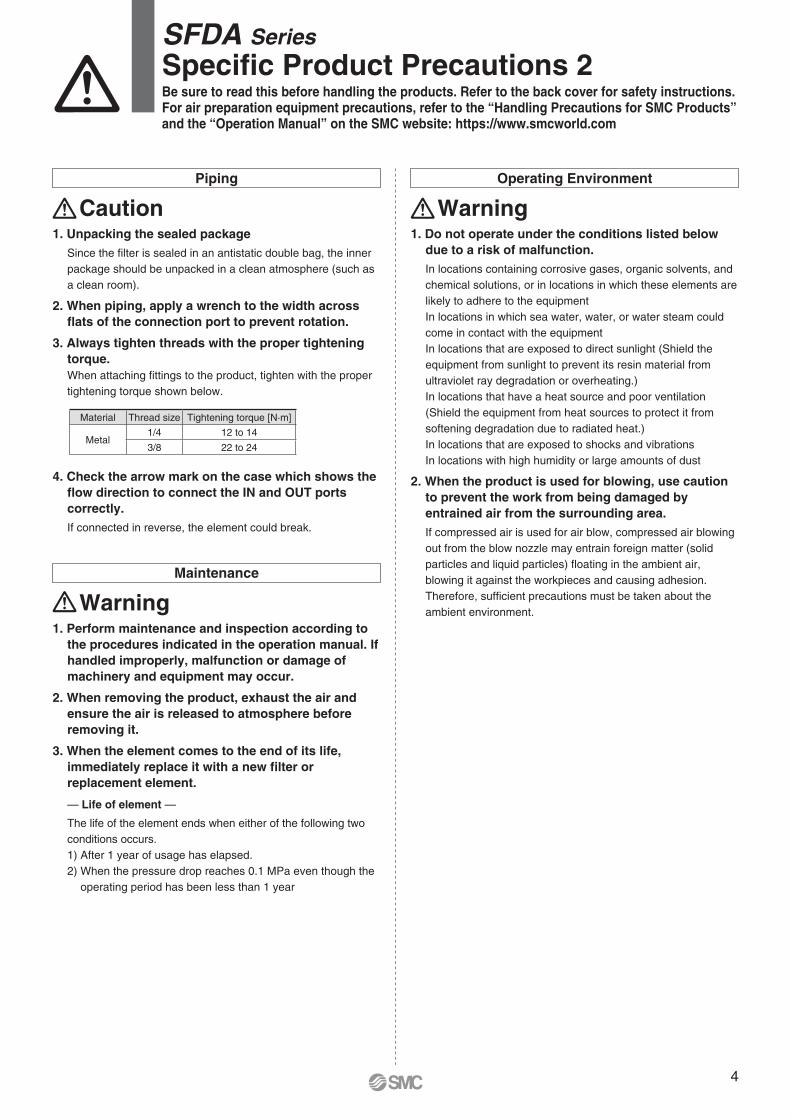
Caution1. Unpacking the sealed package
Since the fi lter is sealed in an antistatic double bag, the inner
package should be unpacked in a clean atmosphere (such as
a clean room).
2. When piping, apply a wrench to the width across
fl ats of the connection port to prevent rotation.
3. Always tighten threads with the proper tightening
torque.
When attaching fi ttings to the product, tighten with the proper
tightening torque shown below.
4. Check the arrow mark on the case which shows the
fl ow direction to connect the IN and OUT ports
correctly.
If connected in reverse, the element could break.
Operating Environment
Warning1. Do not operate under the conditions listed below
due to a risk of malfunction.
In locations containing corrosive gases, organic solvents, and
chemical solutions, or in locations in which these elements are
likely to adhere to the equipment
In locations in which sea water, water, or water steam could
come in contact with the equipment
In locations that are exposed to direct sunlight (Shield the
equipment from sunlight to prevent its resin material from
ultraviolet ray degradation or overheating.)
In locations that have a heat source and poor ventilation
(Shield the equipment from heat sources to protect it from
softening degradation due to radiated heat.)
In locations that are exposed to shocks and vibrations
In locations with high humidity or large amounts of dust
2. When the product is used for blowing, use caution
to prevent the work from being damaged by
entrained air from the surrounding area.
If compressed air is used for air blow, compressed air blowing
out from the blow nozzle may entrain foreign matter (solid
particles and liquid particles) fl oating in the ambient air,
blowing it against the workpieces and causing adhesion.
Therefore, suffi cient precautions must be taken about the
ambient environment.
Maintenance
Warning1. Perform maintenance and inspection according to
the procedures indicated in the operation manual. If
handled improperly, malfunction or damage of
machinery and equipment may occur.
2. When removing the product, exhaust the air and
ensure the air is released to atmosphere before
removing it.
3. When the element comes to the end of its life,
immediately replace it with a new fi lter or
replacement element.
— Life of element —
The life of the element ends when either of the following two
conditions occurs.
1) After 1 year of usage has elapsed.
2) When the pressure drop reaches 0.1 MPa even though the
operating period has been less than 1 year
Material Thread size Tightening torque [N·m]
Metal1/4 12 to 14
3/8 22 to 24
Be sure to read this before handling the products. Refer to the back cover for safety instructions. For air preparation equipment precautions, refer to the “Handling Precautions for SMC Products” and the “Operation Manual” on the SMC website: https://www.smcworld.com
SFDA Series
Specifi c Product Precautions 2
4


These safety instructions are intended to prevent hazardous situations and/or equipment damage. These instructions indicate the level of potential hazard with the labels of “Caution,” “Warning” or “Danger.” They are all important notes for safety and must be followed in addition to International Standards (ISO/IEC) 1), and other safety regulations.
1) ISO 4414: Pneumatic fl uid power – General rules relating to systems.ISO 4413: Hydraulic fl uid power – General rules relating to systems.IEC 60204-1: Safety of machinery – Electrical equipment of machines.
(Part 1: General requirements)ISO 10218-1: Manipulating industrial robots - Safety.etc.
Safety Instructions
Caution:Caution indicates a hazard with a low level of risk which, if not avoided, could result in minor or moderate injury.
Warning:Warning indicates a hazard with a medium level of risk which, if not avoided, could result in death or serious injury.
Danger:Danger indicates a hazard with a high level of risk which, if not avoided, will result in death or serious injury.
Caution1. The product is provided for use in manufacturing industries.
The product herein described is basically provided for peaceful use in manufacturing industries. If considering using the product in other industries, consult SMC beforehand and exchange specifi cations or a contract if necessary.If anything is unclear, contact your nearest sales branch.
CautionSMC products are not intended for use as instruments
for legal metrology.
Measurement instruments that SMC manufactures or sells have not been qualifi ed by type approval tests relevant to the metrology (measurement) laws of each country.Therefore, SMC products cannot be used for business or certifi cation ordained by the metrology (measurement) laws of each country.
Limited warranty and
Disclaimer/ Compliance
RequirementsThe product used is subject to the following “Limited warranty and Disclaimer” and “Compliance Requirements”. Read and accept them before using the product.
Limited warranty and Disclaimer1. The warranty period of the product is 1 year in service or 1.5
years after the product is delivered, whichever is fi rst. 2) Also, the product may have specifi ed durability, running distance or replacement parts. Please consult your nearest sales branch.
2. For any failure or damage reported within the warranty period which is clearly our responsibility, a replacement product or necessary parts will be provided. This limited warranty applies only to our product independently, and not to any other damage incurred due to the failure of the product.
3. Prior to using SMC products, please read and understand the warranty terms and disclaimers noted in the specifi ed catalogue for the particular products.
2) Vacuum pads are excluded from this 1 year warranty.A vacuum pad is a consumable part, so it is warranted for a year after it is delivered. Also, even within the warranty period, the wear of a product due to the use of the vacuum pad or failure due to the deterioration of rubber material are not covered by the limited warranty.
Compliance Requirements1. The use of SMC products with production equipment for the
manufacture of weapons of mass destruction (WMD) or any other weapon is strictly prohibited.
2. The exports of SMC products or technology from one country to another are governed by the relevant security laws and regulations of the countries involved in the transaction. Prior to the shipment of a SMC product to another country, assure that all local rules governing that export are known and followed.
Safety Instructions Be sure to read “Handling Precautions for SMC Products” (M-E03-3) before using.
Warning1. The compatibility of the product is the responsibility of the person
who designs the equipment or decides its specifi cations.
Since the product specifi ed here is used under various operating conditions, its compatibility with specifi c equipment must be decided by the person who designs the equipment or decides its specifi cations based on necessary analysis and test results. The expected performance and safety assurance of the equipment will be the responsibility of the person who has determined its compatibility with the product. This person should also continuously review all specifi cations of the product referring to its latest catalogue information, with a view to giving due consideration to any possibility of equipment failure when confi guring the equipment.
2. Only personnel with appropriate training should operate machinery
and equipment.
The product specifi ed here may become unsafe if handled incorrectly. The assembly, operation and maintenance of machines or equipment including our products must be performed by an operator who is appropriately trained and experienced.
3. Do not service or attempt to remove product and machinery/
equipment until safety is confi rmed.
1. The inspection and maintenance of machinery/equipment should only be performed after measures to prevent falling or runaway of the driven objects have been confi rmed.
2. When the product is to be removed, confi rm that the safety measures as mentioned above are implemented and the power from any appropriate source is cut, and read and understand the specifi c product precautions of all relevant products carefully.
3. Before machinery/equipment is restarted, take measures to prevent unexpected operation and malfunction.
4. Contact SMC beforehand and take special consideration of safety
measures if the product is to be used in any of the following
conditions.
1. Conditions and environments outside of the given specifi cations, or use outdoors or in a place exposed to direct sunlight.
2. Installation on equipment in conjunction with atomic energy, railways, air navigation, space, shipping, vehicles, military, medical treatment, combustion and recreation, or equipment in contact with food and beverages, emergency stop circuits, clutch and brake circuits in press applications, safety equipment or other applications unsuitable for the standard specifi cations described in the product catalogue.
3. An application which could have negative effects on people, property, or animals requiring special safety analysis.
4. Use in an interlock circuit, which requires the provision of double interlock for possible failure by using a mechanical protective function, and periodical checks to confi rm proper operation.

Specifi cations are subject to change without prior notice and any obligation on the part of the manufacturerPrinting YZ 00 Printed in Spain
Austria +43 (0)2262622800 www.smc.at offi [email protected] +32 (0)33551464 www.smc.be [email protected] +359 (0)2807670 www.smc.bg offi [email protected] Croatia +385 (0)13707288 www.smc.hr offi [email protected] Republic +420 541424611 www.smc.cz offi [email protected] Denmark +45 70252900 www.smcdk.com [email protected] Estonia +372 6510370 www.smcpneumatics.ee [email protected] +358 207513513 www.smc.fi smcfi @smc.fi France +33 (0)164761000 www.smc-france.fr [email protected] +49 (0)61034020 www.smc.de [email protected] +30 210 2717265 www.smchellas.gr [email protected] +36 23513000 www.smc.hu offi [email protected] +353 (0)14039000 www.smcautomation.ie [email protected] +39 03990691 www.smcitalia.it [email protected] +371 67817700 www.smc.lv [email protected]
Lithuania +370 5 2308118 www.smclt.lt [email protected] +31 (0)205318888 www.smc.nl [email protected] +47 67129020 www.smc-norge.no [email protected] +48 222119600 www.smc.pl offi [email protected] +351 214724500 www.smc.eu [email protected] +40 213205111 www.smcromania.ro [email protected] +7 8123036600 www.smc.eu [email protected] +421 (0)413213212 www.smc.sk offi [email protected] +386 (0)73885412 www.smc.si offi [email protected] +34 945184100 www.smc.eu [email protected] +46 (0)86031200 www.smc.nu [email protected] +41 (0)523963131 www.smc.ch [email protected] +90 212 489 0 440 www.smcpnomatik.com.tr [email protected] UK +44 (0)845 121 5122 www.smc.uk [email protected]
SMC Corporation (Europe)