ball-guideways · international standarddesign ... · bcs-b kompakte ausführung mit kugelkette,...
TRANSCRIPT

Kugelumlaufführungen · Internationales Standarddesign
Ball-Guideways · International Standarddesign
Rollenumlaufführungen · Roller-Guideways
Kreuzrollenführungen · Cross roller guides
www.rodriguez.de

Profilschienenführungen · Linear Guideways2
Vorteile Kugelumlaufführungen · Advantages Ball Linear Guideways
Weglebensdauer unter Schwerlast = 400 kmcalculated life with heavy load = 400 km
Schwerlast · heavy load
Mittlere Last · medium load
Geringe Last · light load
Weglebensdauer (km) · Operation distance
Vorgesetzte SchmierkammerSelf lubricant carriage
Standardlaufwagen ohne SchmierkammerNo self lubricant carriage
455 km (Weg · Operation)
973 km (Weg · Operation)
2.000 km (Weg · Operation)
29.000 km (Weg · Operation)
0 500 1.000 1.500 2.000 20.000
Vorgesetzte SchmierkammerSelf lubricant carriage
Standardlaufwagen ohne SchmierkammerNo self lubricant carriage
622 cc
10 cc
Vorgesetzte Schmierkammer Self lubricant carriage
Manuelle Schmierung
Lubrication by a manual grease pump
Standardlaufwagen ohne Schmierkammer No self lubricant carriage
Beispiel · ExampleBedingungenCondition
Schwerlastheavy load
mittlere Lastmedium load
geringe Lastlight load
Belastung · Load 18,6 kN 9,3 kN 1,4 kNGeschwindigkeit Speed
50 m/min 50 m/min 300 m/min
Weg · Operation 400 km 3200 km
Standardlaufwagen ohne Schmierkammer: 0,03cc/6min x 8h/Tag x 276 Tag x 1 Jahr = 662ccWeglebensdauer = 3.500 km/JahrNo self lubricant carriage: 0,03cc/6min x 8h/day x 276 day x 1 year = 662cc Operation distance = 3.500 km/year
Vorteil 1 · Advantage 1:Wartungsarm, kein zusätzliches Schmiersystem erforderlich* Free maintance, no extra lubricant system or equipment necessary *
Vorteil 2 · Advantage 2:Verlängerung der Wartungsintervalle Extended maintenance intervals
Vorteil 4 · Advantage 4:Sauber und medienresistent · Environmentally beneficant
Vorteil 3 · Advantage 3:Schmierstoffeinsparung · Reduction of required lubricant
*Präzisionslaufwagen mit vorgesetzter Schmierkammer sind nur in den Größen 15, 20, 25 + 30 verfügbar*Selflubricant Precision Carrier are only available in sizes 15, 20, 25 + 30Bitte beachten Sie auch die Hinweise auf Seite 7 · Please notice the information on page 7

3Profilschienenführungen · Linear Guideways
Kugelumlaufführungen · Ball Linear Guideways
Bestellschlüssel · Ordering code 4
Technische Eigenschaften · Technical properties 5
BRH-A/-AL Standardausführung mit Flansch 13 Standard with flange
BRH-B/-BL Standardausführung ohne Flansch 14 Standard without flange
BRS-B/-BS Kompakte Ausführung · Compact 15
LMBM Miniaturausführung · Miniature 16
BRS-A Kompakte Ausführung, mit Flansch · Compact, with flange 17
BCH-A Standardausführung mit Kugelkette, mit Flansch 18 Standard with ball-cage, with flange
BCH-B Standardausführung mit Kugelkette, ohne Flansch 19 Standard with ball-cage, without flange
BCS-B Kompakte Ausführung mit Kugelkette, ohne Flansch 20 Compact with ball-cage, without flange
Optionen · Options 21
HK Manuelle Klemmelemente · Manual clamp elements 22
Rollenumlaufführungen · Roller Linear Guideways
Bestellschlüssel Rollenumlaufführung + Optionen 23 Ordering code Roller Linear Guideways + Options
Technische Eigenschaften Rollenumlaufführung 24 Technical properties Roller Linear Guideways
MSR…E / LE Rollenumlaufführung, Standardausführung mit Flansch 25 Roller Linear guideway, Standard with flange
MSR…S / LS Rollenumlaufführung, Standardausführung ohne Flansch 26 Roller Linear guideway, Standard without flange
Kreuzrollenführungen · Cross roller guides
KRFT 27
KRF 28
KRFU 30
Inhalt · Content
Kuge
lum
lauf
führ
unge
n · B
all L
inea
r Gu
idew
ays
Kreu
zrol
lenf
ühru
ngen
· Cr
oss
rolle
r gu
ides
Rolle
num
lauf
… ·
Rolle
r Li
near
…

4 Profilschienenführungen · Linear Guideways
Kuge
lum
lauf
führ
unge
n · B
all L
inea
r Gu
idew
ays
Bestellschlüssel · Ordering Code
Beispiel · Sample: BCH-25-A-2-500-N-Z0-II-C
BCH 1. Ausführung
Type
BRH Internationaler Standard International standard
BRS Kompakte Ausführung · Compact version BCH Standardausführung mit Kugelkette
Standard with ball-cage BCS Kompakte Ausführung mit Kugelkette
Compact with ball-cage BCX Kompakte Ausführung mit Kugelkette
Compact with ball-cage BCN niedrige Ausführung mit Kugelkette
low version with ball-cage LMBM Miniaturausführung · Miniature Standard LMBM Miniaturausführung mit Kugelkette
Miniature with ball-cageBRT Internationaler Standard, von unten montierbar
International Standard, assembly from the bottomBRTS kompakte Ausführung, von unten montierbar
Compact, assembly from the bottomBCT Standard mit Kugelkette, von unten montierbar
Standard with ball-cage, assembly from the bottomBCTS kompakte Ausführung mit Kugelkette,
von unten montierbar Compact version with ball-cage, assembly from the bottom
25 2. Größe
Size
A 3. Bauart
Version
A mit Flansch with flange
B ohne Flansch without flange
AL lang, mit Flansch long, with flange
BL lang, ohne Flansch long, without flange
AS kurz, mit Flansch short, with flange
BS kurz, ohne Flansch short, without flange
2 4. Anzahl der Laufwagen
pro Schiene Number of carriages per rail
500 5. Schienenlänge
Rail length
N 6. Genauigkeit
AccuracyN Normal · NormalH Hoch · HighP Präzision · Precision
Z0 7. Vorspannung
PreloadZF spielbehaftet · clearanceZ0 ohne Vorspannung · no preloadZ1 leichte Vorspannung · light preloadZ2 mittlere Vorspannung · medium preloadZ3 starke Vorspannung · heavy preload
II 8. Sets pro Achse
Sets per axis
C 9. Optionen
OptionsA inkl. Längsdichtung*
incl. All-around-seal*B Blechabstreifer · metalscratcherT externes Schmierstoffreservoir
external oiltankC Metallabdeckband
steel cover stripeCF nur Montagehilfe für „C“
only assembly tool for “C”CG nur Halter für „C“ · only holder for “C”CR korrosionsbeständige Oberfläche
corrosionresistant surfaceX schwarz verchromt · black oxidationH hartverchromt · hard chrome platedP phosphatiert · phosphate platingN vernickelt · nickle plating*O Schmierbohrung oben
lubrication hole on top
* nur erforderlich für die Baureihe BRH; die Längsdichtung ist bei der Baureihe BC standardmäßig vorgesehen
* only required for BRH-range; all-around-seal is a standard feature for the BCH-range
Beschichtete Führungswagen werden mit Stahlkugeln ausgerüstet; falls Edelstahlkugeln gewünscht sind, bitte ausdrücklich darauf hinweisen.Coated carriages will be equipped with steelballs; if stainless steel balls are requested, please make a notice.

5Profilschienenführungen · Linear Guideways
Kuge
lum
lauf
führ
unge
n · B
all L
inea
r Gu
idew
ays
Technische Eigenschaften · Technical properties
d1
a
a b
b
d1
d2
d2
3.14*d13.14*d1 d1
b
a a
d2
d1
d2
b’ b’
a'
3.14*d2
Detail A-A
A
DifferentialschlupfDifferential slip
Detail B-B
Kontak
t�äch
e
Contac
t widt
h
Kontak
t�äch
e
Contac
t widt
h
DifferentialschlupfDifferential slip
A B
B
3.14*d2
a'
Gegenüberstellung:1. Leichtlauf: Das 2-Punkt-Kontaktprofil hat einen kleine-
ren Differentialschlupf als das 4-Punkt-Kontaktprofil.
2. Einfachere Montage: Die 4-rehige Ausführung in X-Anordnung mit 45° Druckwinkel gewährleistet den idealen 2-Punkt-Kontakt. Das verbessert die Selbst-ausrichtung und macht das System unempfindlicher gegenüber Fluchtungsfehlern.
3. Reibung: Bedingt durch die 2-Punkt-Kontakte ergeben sich auch bei Erhöhung der Vorspannung keine großen Reibungsverluste.
4. Hohe Tragzahlen: Das 2-Punkt Kontaktprofil hat mit 52% - 53% eine höhere Konformität als das 4-Punkt-Kontaktprofil mit 55% - 60%, was somit höhere Trag-zahlen beim 2-Punkt-Kontaktprofil ergeben.
Gegenüberstellung von 4-reihigen zu 2-reihigen Systemen
Comparison between 4-row system and 2-row system
Comparison :1. Light motion: The 2-point-contact profile has a small-
er differential slip than 4-point-contact.
2. Easy assembly: The 4-row design in X-arrange-ment with 45° contact angle guarantees the ideal 2-point-contact. This improves the system's self-align-ing capability and the better ability of absorbing mis-alignment.
3. Low frictional resistance: Due to the 2-point-con-tact, even under preload the friction will not increase significantly.
4. High load rating: The 2-point-contact profile has a higher conformity with 52% - 53% than the 4-point-contact profile with 55% - 60%. Thus, you have higher load capacities at the 2-point-contact pro-file.
4-reihige Ausführung, 2-Punkt-Kontakt 4-row 2-point-contact
2-reihige Ausführung, 4-Punkt-Kontakt2-row 4-point-contact

6 Profilschienenführungen · Linear Guideways
Kuge
lum
lauf
führ
unge
n · B
all L
inea
r Gu
idew
ays
Technische Eigenschaften · Technical properties
C
A
BW A
BW
CD D
XX-5 XX-5
H H
GeschliffeneAnschlag-
kanteGrindingsurface
GeschliffeneAnschlag-
kanteGrindingsurface
∆D
∆C
(µm)
Schienenlänge · Length of rail (mm)
Präzision · Precision (P)
Hoch · High (H)
4000300020001000
40
30
20
10
0
Einheit · Unit: mm
Ausführung Item
Normal (N) Normal
Hoch (H) - Standard High
Präzision (P) Precision
Höhentoleranz (H) Heighttolerance (H) ±0,1 ±0,04 0
-0,04Breitentoleranz (W) Widthtolerance (W) ±0,1 ±0,04 0
-0,04Höhenunterschied (H)1
Height difference (H)1 0,03 0,02 0,01
Breitenunterschied (W)1
Width difference (W)1 0,03 0,02 0,01
Laufparallelität der Fläche C bezogen auf die Fläche A C: Diagramm 1Runningparallelism of BR Carriage surface C with respect to surface A C: diagram 1Laufparallelität der Fläche D bezogen auf die Fläche B D: Diagramm 1Runningparallelism of BR Carriage surface D with respect to surface B D: diagram 1
1 Unterschied zwischen mehreren Führungswagen auf einer Schiene an derselben Position auf der Schiene 1 Difference between more than one carriage on the same rail at the same position of the rail
Diagramm 1: Schienenlänge und Parallelitätsabweichung Diagram 1: BR rail length and running parallelism
Genauigkeitsklasse · Accuracy class
Vorspannungsklasse · Preload grade classC : Dynamische Tragzahl · Basic dynamic load rating
Vorspannungsklasse · Item Grade Symbol Vorspannkraft · Preload forcespielbehaftet · clearance ZF 0ohne Vorspannung · no preload Z0 0leichte Vorspannung · light preload Z1 0 - 0,02 Cmittlere Vorspannung · medium preload Z2 0,02 - 0,05 Cstarke Vorspannung · heavy preload Z3 0,05 - 0,07 C
7Profilschienenführungen · Linear Guideways
Kuge
lum
lauf
führ
unge
n · B
all L
inea
r Gu
idew
ays
Technische Eigenschaften · Technical properties
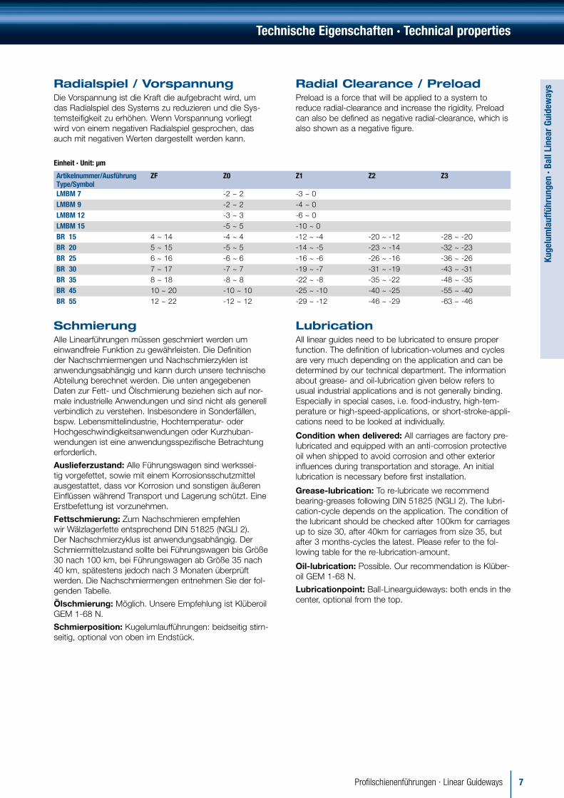
Einheit · Unit: µm
Artikelnummer/Ausführung Type/Symbol
ZF Z0 Z1 Z2 Z3
LMBM 7 -2 ~ 2 -3 ~ 0LMBM 9 -2 ~ 2 -4 ~ 0LMBM 12 -3 ~ 3 -6 ~ 0LMBM 15 -5 ~ 5 -10 ~ 0BR 15 4 ~ 14 -4 ~ 4 -12 ~ -4 -20 ~ -12 -28 ~ -20BR 20 5 ~ 15 -5 ~ 5 -14 ~ -5 -23 ~ -14 -32 ~ -23BR 25 6 ~ 16 -6 ~ 6 -16 ~ -6 -26 ~ -16 -36 ~ -26BR 30 7 ~ 17 -7 ~ 7 -19 ~ -7 -31 ~ -19 -43 ~ -31BR 35 8 ~ 18 -8 ~ 8 -22 ~ -8 -35 ~ -22 -48 ~ -35BR 45 10 ~ 20 -10 ~ 10 -25 ~ -10 -40 ~ -25 -55 ~ -40BR 55 12 ~ 22 -12 ~ 12 -29 ~ -12 -46 ~ -29 -63 ~ -46
Radialspiel / VorspannungDie Vorspannung ist die Kraft die aufgebracht wird, um das Radialspiel des Systems zu reduzieren und die Sys-temsteifigkeit zu erhöhen. Wenn Vorspannung vorliegt wird von einem negativen Radialspiel gesprochen, das auch mit negativen Werten dargestellt werden kann.
Radial Clearance / PreloadPreload is a force that will be applied to a system to reduce radial-clearance and increase the rigidity. Preload can also be defined as negative radial-clearance, which is also shown as a negative figure.
SchmierungAlle Linearführungen müssen geschmiert werden um einwandfreie Funktion zu gewährleisten. Die Definition der Nachschmiermengen und Nachschmierzyklen ist anwendungsabhängig und kann durch unsere technische Abteilung berechnet werden. Die unten angegebenen Daten zur Fett- und Ölschmierung beziehen sich auf nor-male industrielle Anwendungen und sind nicht als generell verbindlich zu verstehen. Insbesondere in Sonderfällen, bspw. Lebensmittelindustrie, Hochtemperatur- oder Hochgeschwindigkeitsanwendungen oder Kurzhuban-wendungen ist eine anwendungsspezifische Betrachtung erforderlich.
Auslieferzustand: Alle Führungswagen sind werkssei-tig vorgefettet, sowie mit einem Korrosionsschutzmittel ausgestattet, dass vor Korrosion und sonstigen äußeren Einflüssen während Transport und Lagerung schützt. Eine Erstbefettung ist vorzunehmen.
Fettschmierung: Zum Nachschmieren empfehlen wir Wälzlagerfette entsprechend DIN 51825 (NGLI 2). Der Nachschmierzyklus ist anwendungsabhängig. Der Schmiermittelzustand sollte bei Führungswagen bis Größe 30 nach 100 km, bei Führungswagen ab Größe 35 nach 40 km, spätestens jedoch nach 3 Monaten überprüft werden. Die Nachschmiermengen entnehmen Sie der fol-genden Tabelle.
Ölschmierung: Möglich. Unsere Empfehlung ist Klüberoil GEM 1-68 N.
Schmierposition: Kugelumlaufführungen: beidseitig stirn-seitig, optional von oben im Endstück.
LubricationAll linear guides need to be lubricated to ensure proper function. The definition of lubrication-volumes and cycles are very much depending on the application and can be determined by our technical department. The information about grease- and oil-lubrication given below refers to usual industrial applications and is not generally binding. Especially in special cases, i.e. food-industry, high-tem-perature or high-speed-applications, or short-stroke-appli-cations need to be looked at individually.
Condition when delivered: All carriages are factory pre-lubricated and equipped with an anti-corrosion protective oil when shipped to avoid corrosion and other exterior influences during transportation and storage. An initial lubrication is necessary before first installation.
Grease-lubrication: To re-lubricate we recommend bearing-greases following DIN 51825 (NGLI 2). The lubri-cation-cycle depends on the application. The condition of the lubricant should be checked after 100km for carriages up to size 30, after 40km for carriages from size 35, but after 3 months-cycles the latest. Please refer to the fol-lowing table for the re-lubrication-amount.
Oil-lubrication: Possible. Our recommendation is Klüber-oil GEM 1-68 N.
Lubricationpoint: Ball-Linearguideways: both ends in the center, optional from the top.

8 Profilschienenführungen · Linear Guideways
Kuge
lum
lauf
führ
unge
n · B
all L
inea
r Gu
idew
ays
Montagehinweise · Suggestion in Assembly
Geschliffene Anschlagkante · Ground surface
Ra
Ra
xx-5 xx-5
Ra
Ra
Hs
Lb
Hr
Geschliffene Anschlagkante · Ground surface
Einheit· Unit: mm
ArtikelnummerItem
Maximaler Radius Maximum Fillet(Ra)
Maximale HöheMaximum Height(Hr) rail shoulder
Maximale HöheMaximum Height(Hs) carriage shoulder
Empfohlene Schraubenlänge *Rail Bolt Length(Lb) suggestion *
BR 15 0,8 3,5 4 M4*16
BR 20 0,8 4 5 M5*20
BR 25 1,2 5 5 M6*25
BR 30 1,2 5 5 M8*30
BR 35 1,2 6 6,5 M8*30
BR 45 1,6 8 8 M12*40
Zulässige Toleranz der Montagefläche Permissible tolerances of mounting surfaces
e1
e2 500
Einheit · Unit: µm
ArtikelnummerItem
Zulässige Toleranzen bzgl. Parallelität (e1)Permissible tolerances for parallelism (e1)
Zulässiger Höhenunterschied (e2)Permissible tolerances of two level offset (e2)
Z3 Z2 Z1 Z0 ZF Z3 Z2 Z1 Z0 ZFBR 15 18 25 35 85 130 190BR 20 18 20 25 35 50 85 130 190BR 25 15 20 22 30 42 60 70 85 130 195BR 30 20 27 30 40 55 80 90 110 170 250BR 35 22 30 35 50 68 100 120 150 210 290BR 45 25 35 40 60 85 110 140 170 250 350
Technische Eigenschaften · Technical properties
Empfohlene Nachschmiermengen · Recommended re-lubrication amounts Einheit · Unit: ml
AusführungVersion
BRH-15-A BRH-15-B BRS-15-B
BRS-15-BS BRH-20-A BRH-20-B BRS-20-B BRS-20-BS
BRH-20-AL BRH-20-BL
BRH-25-A BRH-25-B
BRS-25-B BRS-25-BS
BRH-25-AL BRH-25-BL
BRH-30-A BRH-30-B BRS-30-BS
NachschmiermengeRe-lubrication amount 2 - 3 1 - 2 2 - 3 3 - 4 3 - 4 2 - 3 4 - 6 4 - 6
AusführungVersion
BRS-30-BS BRH-30-AL BRH-30-BL
BRH-35-A BRH-35-B BRS-35-B
BRS-35-BS BRH-35-AL BRH-35-BL
BRH-45-A BRH-45-B BRS-45-B
BRH-45-ALBRH-45-BL
NachschmiermengeRe-lubrication amount 3 - 5 6 - 8 6 - 8 4 - 6 7 - 10 9 - 14 11 - 17
Während des Nachschmierens sollten die Führungswagen mehrfach um 2 Wagenlängen verfahren werden.Please move the carriages for at least 2 carriage-lengths multiple times during the re-lubrication-process.Alle anderen Ausführungen auf Anfrage · All other versions to be inquired.

9Profilschienenführungen · Linear Guideways
Kuge
lum
lauf
führ
unge
n · B
all L
inea
r Gu
idew
ays
Reibungskoeffizient: µ · Coefficient of friction: µDiagramm 2 · diagram 2
0 0.1
0.015
0.010
0.005
0.2
Rei
bung
skoe
f�zi
ent (
µ)C
oef�
cien
t of f
rictio
n (µ
)
PC-Wert · Load ratio (P / C)P: Belastung · LoadC: Dynamische Tragzahlen · Basic dynamic load rating
Widerstand der Dichtungen · Seal resistance: fEinheit · Unit: N
ArtikelnummerModel No.
WiderstandResistance
ArtikelnummerModel No.
WiderstandResistance
BR 15 0,4 BR 30 0,8
BR 20 0,5 BR 35 0,95BR 25 0,6 BR 45 1,4
Schraubenanzugsmomente · Tightening torque of screwEinheit · Unit: Nm
SchraubengrößeScrew size
AnzugsmomentTightening torque
SchraubengrößeScrew size
AnzugsmomentTightening torque
M4 2,5 M10 43M5 5,1 M12 75M6 8,6 M14 121M8 21 M16 196
* Wir empfehlen den Einsatz von Schrauben der Qualität 12.9. * We recommend to use screw in quality 12.9.
Verschiebewiderstand Der Verschiebewiderstand kann mit Hilfe folgender Formel errechnet werden.
F = µ x W + f
F : Verschiebekraft W : Belastungµ : Reibungskoeffizient f : Widerstand der Dichtungen
Frictional resistance The frictional resistance can be calculated from the following formula.
F = µ x W + f
F : frictional resistance W : loadµ : coefficient of friction f : seal resistance
Technische Eigenschaften · Technical properties

10 Profilschienenführungen · Linear Guideways
Kuge
lum
lauf
führ
unge
n · B
all L
inea
r Gu
idew
ays
xx-5
Lmax
G G
My
Mz
Mx
Definition der Lebensdauer
Statische Tragzahlen C0Wenn ein lineares Führungssystem, entweder im stati-schen Zustand oder unter Bewegung, extrem belastet wird, kommt es häufig zu permanenten Deformationen zwischen Laufbahn und Kugeln. Wenn diese Deformati-on zu groß wird, wird die Laufeigenschaft des Systems beeinträchtigt.
Die statische Belastung C0 ist die konstante Belastung in eine Richtung, die in der Summe eine Deformation der Wälzkörper und Laufbahnen erzeugt. Diese entspricht dem 0,0001-fachen des Wälzkörperdurchmessers.
Zulässige statische Momentbelastung M0Wenn ein lineares Führungssystem mit einem Moment beaufschlagt wird, entsteht an den Wälzkörpern, die sich am jeweiligen Ende des Führungssystems befinden, die maximale Belastung.
Das zulässige statische Moment M0 ist das Moment, wel-ches aus seiner resultierenden Last in eine Richtung in der Summe eine Deformation der Wälzkörper und Laufbahnen erzeugt, die dem 0,0001-fache des Wälzkörperdurchmes-sers entspricht.
Zulässige statische Momentbelastung Mx, My, MzIn linearen Führungssystemen werden statische Momente Mx, My und Mz definiert. Diese entsprechen dem stati-schen Moment Mo in den jeweiligen Achsrichtungen X, Y und Z.
Definition of Load and Life
Basic static load rating C0When a linear motion system in the static state or in motion is subject to an extreme load or impact, a per-manent deformation will occur between raceway and rolling elements. If the deformation is excessive, the linear motion system can not travel smoothly.
Now, we define the basic static load rating C0 is a static load of constant magnitude acting in one direction under which the sum of the permanent deformations of rolling elements and raceway equals 0,0001 times the diameter of the rolling elements.
Static permissible moment M0When a linear motion system is subject to a moment load, the maximum stress occurs in the rolling elements at both ends. The static permissible moment M0 is a moment of constant magnitude acting in one direction under which the sum of the permanent deformations of rolling ele-ments and raceway equals 0,0001 times the diameter of the rolling elements.
Basic static permissible moment Mx, My, MzIn the linear motion system, we define basic static permis-sible moments Mx, My and Mz are the moments of the static permissible moment M0 in X, Y and Z direction.
fs = ( fc x C0 ) / P or fs = ( fc x M0 ) / M
fs: statischer Sicherheitsfaktor · static safety factor fc: Kontaktfaktor · Contact factor C0: statische Tragzahl · basic static load rating M0: statisches Moment · static permissible moment P: Belastung · design load M: tatsächliches Moment · design moment
Statischer Sicherheitsfaktor entsprechend untenstehender Tabelle · Reference value of static safety factor fs shown below:
Einsatzbedingungen Operating condition
Belastung Load condition Minimum fs
Normal statischNormal static
Geringe Stoßbelastung u. Schienendurchbiegung · Small impact and deflection 1,0 ~ 1,3
Stoß- u. Torsionsbelastung · Impact or twisting load are applied 2,0 ~ 3,0
Normal dynamischNormal dynamic
Geringe Stoß- u. Torsionsbelastung · Small impact or twisting load are applied 1,0 ~ 1,5
Stoß- u. Torsionsbelastung · Impact or twisting load are applied 2,5 ~ 5,0
Statischer Sicherheitsfaktor fsDer statische Sicherheitsfaktor fs ist das Verhältnis zwi-schen der statischen Tragzahl C0 und der tatsächlichen Belastung des Systems.
Static safety factor fsStatic safety factor fs is the ratio of the basic static load rating C0 to the load acting on the linear motion system.
Technische Eigenschaften · Technical properties

11Profilschienenführungen · Linear Guideways
Kuge
lum
lauf
führ
unge
n · B
all L
inea
r Gu
idew
aysNominelle Lebensdauer L
Als nominelle Lebensdauer bezeichnet man die Gesamt-laufstrecke, die von 90% oder mehr einer ausreichend großen Gruppe gleicher Profilschienenführungen erreicht wird, die alle einzeln unter gleichen Bedingungen mit der Last C belastet werden.
Dynamische Tragzahl CBei Beaufschlagung der Profilschienenführungen mit einer gleichmäßigen und konstanten Last entsprechend den dynamischen Tragzahlen aus dem Katalog in einer Belas-tungsrichtung, entspricht diese nominelle Lebensdauer einer Wegstrecke von 50 Kilometern bei Kugelumlauffüh-rungen und 100 Kilometern bei Rollenumlaufführungen.
Kontaktfaktor: fcBei der Verwendung mehrerer Führungswagen in engen Abständen zueinander im gleichen Führungssystem ist eine gleichmäßige Lastverteilung aufgrund von Montage-fehlern, Momenten, Fertigungstoleranzen und anderen Faktoren nur schwer möglich. In diesen Fällen sollten die Standard Tragzahlen C und C0 mit dem Kontaktfaktor fc aus folgender Tabelle multipliziert werden.
Anzahl der Laufwagen in engem KontaktNumber of carriages in close contact
KontaktfaktorContact factor
2 0,813 0,724 0,665 0,61Normale EinsatzbedingungenNormal operation
1
Nominal life LThe nominal life L is the total distance of travel reached without flaking by 90% of a group of identical linear motion system that are operated independently under the same condition.
Basic dynamic load rating CWhen each of a group of identical linear motion system is applied independently under the same condition, basic dynamic load rating C is the load of constant magnitude acting in one direction that results in a nominal life of 50 km for a system using balls and 100 km for a system using rollers.
Contact factor fcIn linear motion system, it is hard to obtain uniform load distribution in close contact installation due to moments, errors on the mounting surfaces and other factors. When two or more carriages in a rail are used in close contact, multiply basic load ratings C and C0 by the contact fac-tors shown below.
Härtefaktor fhDie maximal zulässige einwirkende Härte beträgt im Bereich der Laufbahnen HRC 56-58.
Wenn diese Härte geringer als HRC 56 ist, verändert sich sowohl die statische als auch die dynamische Tragzahl. Durch Multiplikation mit dem Härtefaktor ermitteln sich die neuen Tragzahlen.
Hardness factor fhFor linear motion system, its optimum load carrying capa-bility is HrC 58 to 64 hardness on the raceways.
If the hardness is lower than HrC 58, both the basic dynamic load rating and basic static load rating should be multiplied by hardness factor fh.
Härte der Laufbahnen (HrC)Hardness of raceway (HrC)
20304050
0.4
0.3
0.2
0.1
60
0.5
0.6
0.7
0.8
0.9
1.0
10
Här
tefa
ktor
(fh)
Har
dnes
s fa
ctor
(fh)
Technische Eigenschaften · Technical properties

12 Profilschienenführungen · Linear Guideways
Kuge
lum
lauf
führ
unge
n · B
all L
inea
r Gu
idew
ays
Belastungsfaktor: fwReversierende Bewegungen verursachen gewöhnlich Vib-rationen, Stöße und variable Belastungen. Vibrationen in Hochgeschwindigkeitsanwendungen, Stöße aus hochdy-namischen Start – Stop Anwendungen und veränderliche Lasten während der Bewegungszyklen erschweren die Kalkulation. Treten diese Faktoren in der Anwendung auf, sollten bei der Auslegung die Tragzahlen C und C0 durch den entsprechenden Faktor fw aus der folgenden Tabelle dividiert werden.
Load factor fwReciprocating motion usually occur vibrations, impacts and variable loads. In general, vibrations occur in high-speed operation, impacts due to repeated starting and stopping and variable loads it is difficult to calculate. When above factor affect the loading conditions signifi-cantly, divided basic load ratings C and C0 by the experi-mentally obtained load factors shown below.
Temperaturfaktor fTWenn die Einsatzbedingungen eine Temperatur von mehr als 100°C verlangen, muß der Temperaturfaktor berück sichtigt werden.
1. Dichtungen und Endkappen müssen eine Sonder-behandlung erfahren, wenn die Einsatzbedingungen eine Temperatur von 80° C übersteigen.
2. Das Gesamtsystem bedarf einer besonderen Behandlung, wenn die Einsatzbedingungen eine Temperatur von 120° C übersteigen.
Temperature factor fTWhen a linear motion system is subject to temperature above 100°C, the temperature factor should be taken into consideration.
1. When used in above 80°C, the seals and end plates should be designed for high temperature operation.
2. When used in above 120°C, special treatment should be designed for stabilizing the dimension
L : nominelle Lebensdauer in km · nominal life in kmC : dynamische Belastung · basic dynamic load ratingP : Belastung · applied load
fw : Belastungsfaktor · Load factorfh: Härtefaktor · Hardness factorfT: Temperaturfaktor · Temperature factorfc: Kontaktfaktor · Contact factor
Kugelumlaufführungen · Ball-Guideways
L = (fh × fT × fc
×C
) 3 × 50FW P
Rollenumlaufführungen · Roller-Guideways
L = (fh × fT × fc
×C
)10
× 1003
FW P
Formel zu Errechnung der Lebensdauer Formula of nominal life L
Stöße und VibrationenImpacts und Vibrations Geschwindigkeit (V)Speed ( V ) Vibration ( G )
Vibration ( G ) fw
Ohne externe Stöße oder VibrationenWithout external Impacts or Vibrations
V <= 15 m/minGeringe Geschwindigkeit · Low speed G <= 0,5 1 ~ 1,5
Ohne nennenswerte Stöße o. VibrationenWithout significant Impacts or Vibrations
15 < V <= 60 m/min Durchschnittliche Geschwindigkeit · Medium speed 0,5 < G <= 1,0 1,5 ~ 2,0
mit externen Stößen oder VibrationenWith external Impacts or Vibrations
V > 60 m/minHohe Geschwindigkeit · High speed 1,0 < G <= 2,0 2,0 ~ 3,5
Technische Eigenschaften · Technical properties
200150100
Temperatur der Laufbahnen (°C) · Raceway temperature (°C)
Tem
pera
turfa
ktor
( fT
) · T
empe
ratu
re fa
ctor
( fT
)
0.9
0.8
0.7
0.6
0.5
1.0
13Profilschienenführungen · Linear Guideways
Kuge
lum
lauf
führ
unge
n · B
all L
inea
r Gu
idew
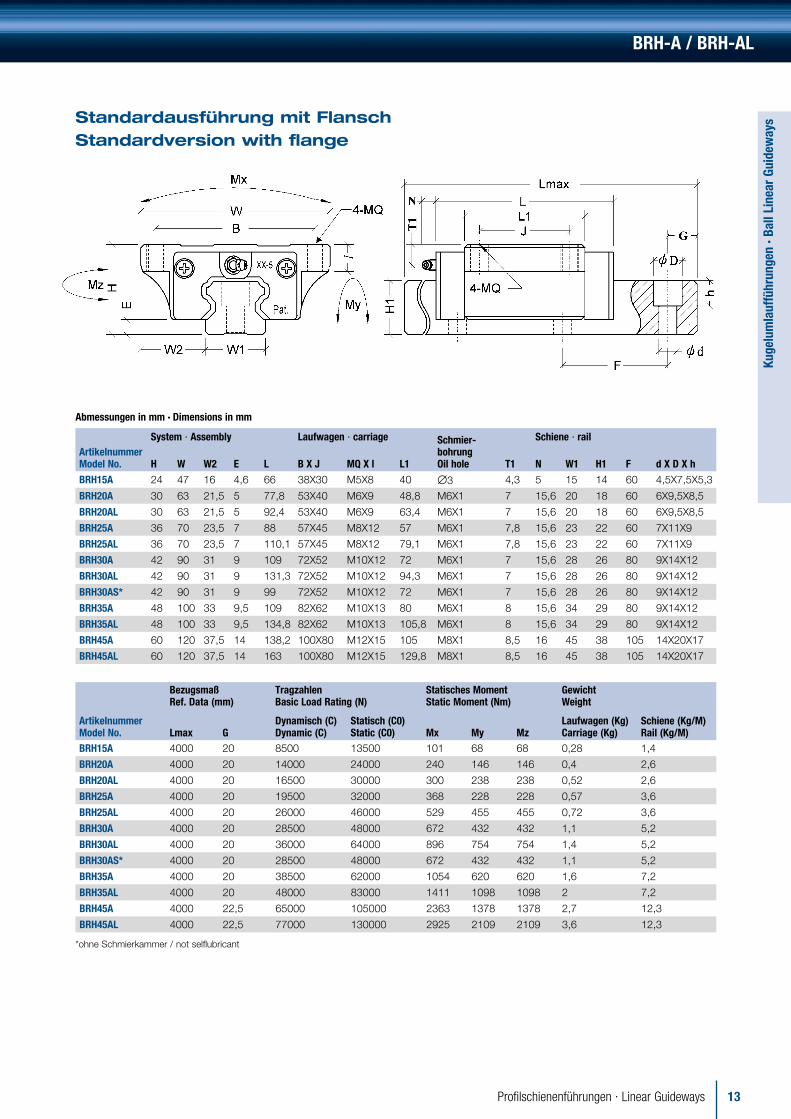
aysStandardausführung mit Flansch
Standardversion with flange
Abmessungen in mm · Dimensions in mm
System ∙ Assembly Laufwagen ∙ carriage Schmier-bohrungOil hole
Schiene ∙ railArtikelnummerModel No. H W W2 E L B X J MQ X l L1 T1 N W1 H1 F d X D X h
BRH15A 24 47 16 4,6 66 38X30 M5X8 40 ∅3 4,3 5 15 14 60 4,5X7,5X5,3
BRH20A 30 63 21,5 5 77,8 53X40 M6X9 48,8 M6X1 7 15,6 20 18 60 6X9,5X8,5
BRH20AL 30 63 21,5 5 92,4 53X40 M6X9 63,4 M6X1 7 15,6 20 18 60 6X9,5X8,5
BRH25A 36 70 23,5 7 88 57X45 M8X12 57 M6X1 7,8 15,6 23 22 60 7X11X9
BRH25AL 36 70 23,5 7 110,1 57X45 M8X12 79,1 M6X1 7,8 15,6 23 22 60 7X11X9
BRH30A 42 90 31 9 109 72X52 M10X12 72 M6X1 7 15,6 28 26 80 9X14X12
BRH30AL 42 90 31 9 131,3 72X52 M10X12 94,3 M6X1 7 15,6 28 26 80 9X14X12
BRH30AS* 42 90 31 9 99 72X52 M10X12 72 M6X1 7 15,6 28 26 80 9X14X12
BRH35A 48 100 33 9,5 109 82X62 M10X13 80 M6X1 8 15,6 34 29 80 9X14X12
BRH35AL 48 100 33 9,5 134,8 82X62 M10X13 105,8 M6X1 8 15,6 34 29 80 9X14X12
BRH45A 60 120 37,5 14 138,2 100X80 M12X15 105 M8X1 8,5 16 45 38 105 14X20X17
BRH45AL 60 120 37,5 14 163 100X80 M12X15 129,8 M8X1 8,5 16 45 38 105 14X20X17
BezugsmaßRef. Data (mm)
TragzahlenBasic Load Rating (N)
Statisches MomentStatic Moment (Nm)
GewichtWeight
ArtikelnummerModel No. Lmax G
Dynamisch (C)Dynamic (C)
Statisch (C0)Static (C0) Mx My Mz
Laufwagen (Kg)Carriage (Kg)
Schiene (Kg/M)Rail (Kg/M)
BRH15A 4000 20 8500 13500 101 68 68 0,28 1,4
BRH20A 4000 20 14000 24000 240 146 146 0,4 2,6
BRH20AL 4000 20 16500 30000 300 238 238 0,52 2,6
BRH25A 4000 20 19500 32000 368 228 228 0,57 3,6
BRH25AL 4000 20 26000 46000 529 455 455 0,72 3,6
BRH30A 4000 20 28500 48000 672 432 432 1,1 5,2
BRH30AL 4000 20 36000 64000 896 754 754 1,4 5,2
BRH30AS* 4000 20 28500 48000 672 432 432 1,1 5,2
BRH35A 4000 20 38500 62000 1054 620 620 1,6 7,2
BRH35AL 4000 20 48000 83000 1411 1098 1098 2 7,2
BRH45A 4000 22,5 65000 105000 2363 1378 1378 2,7 12,3
BRH45AL 4000 22,5 77000 130000 2925 2109 2109 3,6 12,3
*ohne Schmierkammer / not selflubricant
BRH-A / BRH-AL

14 Profilschienenführungen · Linear Guideways
Kuge
lum
lauf
führ
unge
n · B
all L
inea
r Gu
idew
ays
BRH-B / BRH-BL
Standardausführung ohne Flansch Standardversion without flange
Abmessungen in mm · Dimensions in mm
System · Assembly Laufwagen · carriage Schmier-bohrungOil hole
Schiene · railArtikelnummerModel No. H W W2 E L B X J MQ X l L1 T1 N W1 H1 F d X D X hBRH15B 28 34 9,6 4,6 66 26X26 M4X6 40 ∅3 8,3 5 15 14 60 4,5X7,5X5,3
BRH20B 30 44 12 5 77,8 32X36 M5X8 48,8 M6X1 7 13,5 20 18 60 6X9,5X8,5
BRH20BL 30 44 12 5 92,4 32X50 M5X8 63,4 M6X1 7 13,5 20 18 60 6X9,5X8,5
BRH25B 40 48 12,5 7 88 35X35 M6X10 57 M6X1 11,8 15,6 23 22 60 7X11X9
BRH25BL 40 48 12,5 7 110,1 35X50 M6X10 79,1 M6X1 11,8 15,6 23 22 60 7X11X9
BRH30B 45 60 16 9 109 40X40 M8X13 72 M6X1 10 15,6 28 26 80 9X14X12
BRH30BL 45 60 16 9 131,3 40X60 M8X13 94,3 M6X1 10 15,6 28 26 80 9X14X12
BRH35B 55 70 18 9,5 109 50X50 M8X13 80 M6X1 15 15,6 34 29 80 9X14X12
BRH35BL 55 70 18 9,5 134,8 50X72 M8X13 105,8 M6X1 15 15,6 34 29 80 9X14X12
BRH45B 70 86 20,5 14 138,2 60X60 M10X16,5 105 M8X1 18,5 16 45 38 105 14X20X17
BRH45BL 70 86 20,5 14 163 60X80 M10X16,5 129,8 M8X1 18,5 16 45 38 105 14X20X17
BezugsmaßRef. Data (mm)
TragzahlenBasic Load Rating (N)
Statisches MomentStatic Moment (Nm)
GewichtWeight
ArtikelnummerModel No. Lmax G
Dynamisch (C)Dynamic (C)
Statisch (C0)Static (C0) Mx My Mz
Laufwagen (Kg)Carriage (Kg)
Schiene (Kg/M)Rail (Kg/M)
BRH15B 4000 20 8500 13500 101 68 68 0,19 1,4
BRH20B 4000 20 14000 24000 240 146 146 0,31 2,6
BRH20BL 4000 20 16500 30000 300 238 238 0,47 2,6
BRH25B 4000 20 19500 32000 368 228 228 0,45 3,6
BRH25BL 4000 20 26000 46000 529 455 455 0,56 3,6
BRH30B 4000 20 28500 48000 672 432 432 0,91 5,2
BRH30BL 4000 20 36000 64000 896 754 754 1,2 5,2
BRH35B 4000 20 38500 62000 1054 620 620 1,5 7,2
BRH35BL 4000 20 48000 83000 1411 1098 1098 1,9 7,2
BRH45B 4000 22,5 65000 105000 2363 1378 1378 2,3 12,3
BRH45BL 4000 22,5 77000 130000 2925 2109 2109 2,8 12,3

15Profilschienenführungen · Linear Guideways
Kuge
lum
lauf
führ
unge
n · B
all L
inea
r Gu
idew
ays
BRS-B / BRS-BS
Kompakte Ausführung Compact version
Abmessungen in mm · Dimensions in mm
System · Assembly Laufwagen · carriage Schmier-bohrungOil hole
Schiene · railArtikelnummerModel No. H W W2 E L B X J MQ X l L1 T1 N W1 H1 F d X D X hBRS15B 24 34 9,5 4,6 66 26X26 M4X5,6 40 ∅3 4,3 5 15 14 60 4,5X7,5X5,3
BRS15BS 24 34 9,5 4,6 47,6 26X- M4X5,6 21,6 ∅3 4,3 5 15 14 60 4,5X7,5X5,3
BRS20B 28 42 11 5 77,8 32X32 M5X6,4 48,8 M6X1 5 15,6 20 18 60 6X9,5X8,5
BRS20BS 28 42 11 5 57 32X- M5X6,4 28 M6X1 5 15,6 20 18 60 6X9,5X8,5
BRS25B 33 48 12,5 7 88 35X35 M6X8 57 M6X1 4,8 15,6 23 22 60 7X11X9
BRS25BS 33 48 12,5 7 62,5 35X- M6X8 31,5 M6X1 4,8 15,6 23 22 60 7X11X9
BRS30B 42 60 16 9 109 40X40 M8X11,5 72 M6X1 7 15,6 28 26 80 9X14X12
BRS30BS 42 60 16 9 75,6 40X- M8X11,5 38,6 M6X1 7 15,6 28 26 80 9X14X12
BRS35B 48 70 18 9,5 109 50X50 M8X11,2 80 M6X1 8 15,6 34 29 80 9X14X12
BRS35BS 48 70 18 9,5 74,7 50X- M8X11,2 45,7 M6X1 8 15,6 34 29 80 9X14X12
BRS45B 60 86 20,5 14 138,2 60X60 M10X13 105 M8X1 8,5 16 45 38 105 14X20X17
BezugsmaßRef. Data (mm)
TragzahlenBasic Load Rating (N)
Statisches MomentStatic Moment (Nm)
GewichtWeight
ArtikelnummerModel No. Lmax G
Dynamisch (C)Dynamic (C)
Statisch (C0) Static (C0) Mx My Mz
Laufwagen (Kg)Carriage (Kg)
Schiene (Kg/M)Rail (Kg/M)
BRS15B 4000 20 8500 13500 101 68 68 0,17 1,4
BRS15BS 4000 20 5200 6800 510 18 18 0,1 1,4
BRS20B 4000 20 14000 24000 240 146 146 0,26 2,6
BRS20BS 4000 20 9500 14000 70 49 49 0,17 2,6
BRS25B 4000 20 19500 32000 368 228 228 0,38 3,6
BRS25BS 4000 20 12500 17500 175 69 69 0,21 3,6
BRS30B 4000 20 28500 48000 672 432 432 0,81 5,2
BRS30BS 4000 20 17500 24000 336 116 116 0,48 5,2
BRS35B 4000 20 38500 62000 1054 620 62 1,2 7,2
BRS35BS 4000 20 25000 36500 621 209 209 0,48 7,2
BRS45B 4000 22,5 65000 105000 2363 1378 1378 2,1 12,3

16 Profilschienenführungen · Linear Guideways
Kuge
lum
lauf
führ
unge
n · B
all L
inea
r Gu
idew
ays
LMBM
Miniaturausführung Miniature
Abmessungen in mm · Dimensions in mm
ArtikelnummerModel No.
System · Assembly Laufwagen · carriage Schiene · rail
H W W2 E L BxJ MQx1 L1 W1 H1 F dxDxhLMBM7 8 17 5 1,5 23,5 12x8 M2x2,5 13,5 7 4,7 15 2,4x4,2x2,3
LMBM9 10 20 5,5 2,2 31 15x10 M3x3 20 9 5,5 20 3,5x5,5x3,3
LMBM12 13 27 7,5 3 35 20x15 M3x3,5 20,8 12 7,5 25 3,5x6x4,5
LMBM15 16 32 8,5 4 43 25x20 M3x4 25,7 15 9,5 40 3,5x6x4,5
ArtikelnummerModel No.
Bezugsmaß ∙ Ref. DataTragzahlen (N)Basic Load Rating (N)
Statisches Moment (Nm) Static Moment (Nm) Gewicht ∙ Weight
Lmax GDynamisch(C) Dynamic (C)
Statisch (C0) Static (C0) Mx My Mz
Laufwagen (kg) Carriage (kg)
Schiene (kg/m) Rail (kg/m)
LMBM7 570 7,5 880 1370 5,1 2,55 2,55 0,02 0,23
LMBM9 495 7,5 1470 2250 10,4 5,1 5,1 0,02 0,32
LMBM12 590 10 2650 4020 14,7 8,04 8,72 0,04 0,58
LMBM15 790 15 4410 6570 30,2 16,5 17,9 0,07 0,93
Rostbeständige Ausführung · Corrosion resistant
Breite Ausführung · Wide Version
Abmessungen in mm · Dimensions in mm
ArtikelnummerModel No.
System · Assembly Laufwagen · carriage Schiene · rail
H W W2 E L BxJ MQx1 L1 W1 H1 F dxDxhLMBM7W 9 25 5,5 2 31 -x12 M4x3,5 21,5 14 5,2 30 3,5x6x3,2
LMBM9W 12 30 6 4,2 39 21x12 M2,6x3 28 18 7,5 30 3,5x6x4,5
LMBM12W 14 40 8 4 44,5 28x15 M3x3,5 30,5 24 8,5 40 4,5x8x4,5
LMBM15W 16 60 9 4 55,5 45x20 M4x4,5 38,5 42 9,5 40* 4,5x8x4,5
ArtikelnummerModel No.
Bezugsmaß · Ref. DataTragzahlen (N)Basic Load Rating (N)
Statisches Moment (Nm)Static Moment (Nm) Gewicht · Weight
Lmax GDynamisch(C) Dynamic (C)
Statisch (C0) Static (C0) Mx My Mz
Laufwagen (kg) Carriage (kg)
Schiene (kg/m) Rail (kg/m)
LMBM7W 290 10 1370 2160 15,2 5,39 5,39 0,03 0,51
LMBM9W 290 10 2450 3920 36 16,3 16,3 0,04 1,08
LMBM12W 470 15 4020 6080 47,6 17,2 18,6 0,08 1,5
LMBM15W 670 15 6660 9800 137 35,2 38,2 0,17 3
Rostbeständige Ausführung · Corrosion resistant * Doppelte Bohrreihe, Abstand 23 mm · 2 borerows, distance 23 mm
Ohne weitere Angaben wird Vorspannungsklasse Z0 geliefert. Preload class Z0 will be delivered without further notice.
17Profilschienenführungen · Linear Guideways
Kuge
lum
lauf
führ
unge
n · B
all L
inea
r Gu
idew
ays
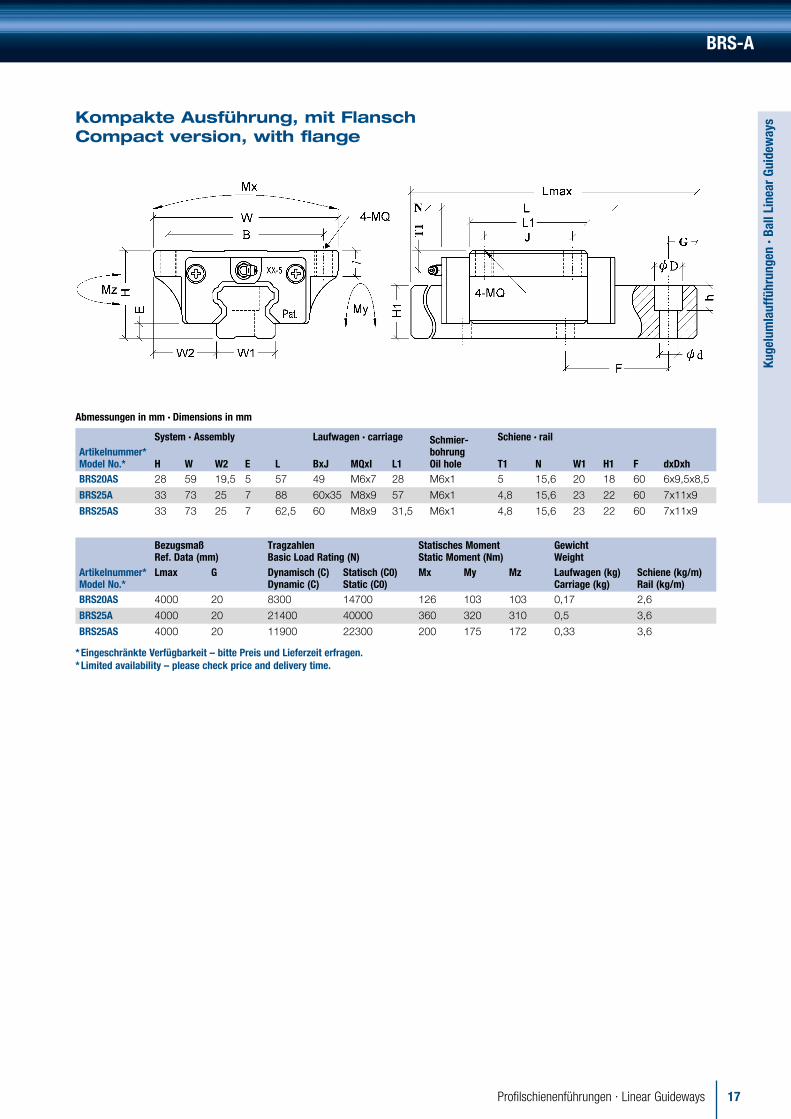
BRS-A
Kompakte Ausführung, mit Flansch Compact version, with flange
Abmessungen in mm · Dimensions in mm
System · Assembly Laufwagen · carriage Schmier-bohrungOil hole
Schiene · railArtikelnummer* Model No.* H W W2 E L BxJ MQxI L1 T1 N W1 H1 F dxDxhBRS20AS 28 59 19,5 5 57 49 M6x7 28 M6x1 5 15,6 20 18 60 6x9,5x8,5
BRS25A 33 73 25 7 88 60x35 M8x9 57 M6x1 4,8 15,6 23 22 60 7x11x9
BRS25AS 33 73 25 7 62,5 60 M8x9 31,5 M6x1 4,8 15,6 23 22 60 7x11x9
BezugsmaßRef. Data (mm)
TragzahlenBasic Load Rating (N)
Statisches MomentStatic Moment (Nm)
GewichtWeight
Artikelnummer* Model No.*
Lmax G Dynamisch (C)Dynamic (C)
Statisch (C0)Static (C0)
Mx My Mz Laufwagen (kg)Carriage (kg)
Schiene (kg/m)Rail (kg/m)
BRS20AS 4000 20 8300 14700 126 103 103 0,17 2,6
BRS25A 4000 20 21400 40000 360 320 310 0,5 3,6
BRS25AS 4000 20 11900 22300 200 175 172 0,33 3,6
* Eingeschränkte Verfügbarkeit – bitte Preis und Lieferzeit erfragen.* Limited availability – please check price and delivery time.

18 Profilschienenführungen · Linear Guideways
Kuge
lum
lauf
führ
unge
n · B
all L
inea
r Gu
idew
ays
BCH-A
Standardausführung mit Kugelkette, mit Flansch Standard with ball-cage, with flange
Abmessungen in mm · Dimensions in mm
Artikelnummer*Model No.*
System · Assembly Laufwagen · carriage Schmierbohrung Oil hole
Schiene · rail
H W W2 E L BXJ MQXI L1 T1 N W1 H1 F d X D X hBCH20A 30 63 21,5 6 87 53x40 M6x10 59 M6x1 7,5 15,6 20 16,5 60 6x9,5x8,5
BCH20AL 30 63 21,5 6 106 53x40 M6x10 78 M6x1 7,5 15,6 20 16,5 60 6x9,5x8,5
BCH25A 36 70 23,5 6 102 57x45 M8x12 71 M6x1 10 15,6 23 20 60 7x11x9
BCH25AL 36 70 23,5 6 119 57x45 M8x12 88 M6x1 10 15,6 23 20 60 7x11x9
BCH30A 42 90 31 7 116 72x52 M10x15 80 M6x1 12 15,6 28 23 80 9x14x12
BCH30AL 42 90 31 7 141 72x52 M10x15 105 M6x1 12 15,6 28 23 80 9x14x12
BCH35A 48 100 33 7,5 132 82x62 M10x17 93 M6x1 12 15,6 34 26 80 9x14x12
BCH35AL 48 100 33 7,5 162 82x62 M10x17 123 M6x1 12 15,6 34 26 80 9x14x12
BCH45A 60 120 37,5 8,9 150 100x80 M12x17 106 M8x1 16 16 45 32 105 14x20x17
BCH45AL 60 120 37,5 8,9 184 100x80 M12x17 140 M8x1 16 16 45 32 105 14x20x17
BCH55A 70 140 43,5 12,7 181 116x95 M14x21 131 M8x1 20 16 53 38 120 16x23x20
BCH55AL 70 140 43,5 12,7 223 116x95 M14x21 173 M8x1 20 16 53 38 120 16x23x20
Bezugsmaß Ref. Data (mm)
TragzahlenBasic Load Rating (N)
Statisches MomentStatic Moment (Nm) Gewichtt · Weight
Artikelnummer*Model No.* Lmax G
Dynamisch (C)Dynamic (C)
Statisch (C0)Static (C0) Mx My Mz
Laufwagen (kg)Carriage (kg)
Schiene (kg/m)Rail (kg/m)
BCH20A 4000 20 21200 36800 329 304 304 0,45 2,3
BCH20AL 4000 20 26800 48300 430 520 520 0,62 2,3
BCH25A 4000 20 30300 50400 513 518 518 0,75 3,2
BCH25AL 4000 20 35200 62300 635 772 772 0,9 3,2
BCH30A 4000 20 43000 64100 790 720 720 1,31 4,5
BCH30AL 4000 20 52100 88500 1050 1240 1240 1,55 4,5
BCH35A 4000 20 60000 93200 1400 1260 1260 1,9 6,2
BCH35AL 4000 20 70200 122600 1740 2140 2140 2,55 6,2
BCH45A 4000 22,5 79800 151500 2450 1870 1870 3,3 10,4
BCH45AL 4000 22,5 96500 160400 3200 3150 3150 4,2 10,4
BCH55A 4000 30 123500 190000 4660 3550 3550 5,4 14,5
BCH55AL 4000 30 155000 249000 5800 6000 6000 7,1 14,5
* Eingeschränkte Verfügbarkeit – bitte Preis und Lieferzeit erfragen.* Limited availability – please check price and delivery time.

19Profilschienenführungen · Linear Guideways
Kuge
lum
lauf
führ
unge
n · B
all L
inea
r Gu
idew
ays
BCH-B
Standardausführung mit Kugelkette, ohne Flansch Standard version with ball-cage, without flange
Abmessungen in mm · Dimensions in mm
Artikelnummer*Model No.*
System · Assembly Laufwagen · carriage SchmierbohrungOil hole
Schiene · rail
H W W2 E L B X J MQ X l L1 T1 N W1 H1 F d X D X hBCH20B 30 44 12 6 87 32x36 M5x7 59 M6x1 7,5 15,6 20 16,5 60 6x9,5x8,5
BCH20BL 30 44 12 6 106 32x50 M5x7 78 M6x1 7,5 15,6 20 16,5 60 6x9,5x8,5
BCH25B 40 48 12,5 6 102 35x35 M6x10 71 M6x1 14 15,6 23 20 60 7x11x9
BCH25BL 40 48 12,5 6 119 35x50 M6x10 88 M6x1 14 15,6 23 20 60 7x11x9
BCH30B 45 60 16 7 116 40x40 M8x12 80 M6x1 15 15,6 28 23 80 9x14x12
BCH30BL 45 60 16 7 141 40x60 M8x12 105 M6x1 15 15,6 28 23 80 9x14x12
BCH35B 55 70 18 7,5 132 50x50 M8x14 93 M6x1 19 15,6 34 26 80 9x14x12
BCH35BL 55 70 18 7,5 162 50x72 M8x14 123 M6x1 19 15,6 34 26 80 9x14x12
BCH45B 70 86 20,5 8,9 150 60x60 M10x16 106 M8x1 26 16 45 32 105 14x20x17
BCH45BL 70 86 20,5 8,9 184 60x80 M10x16 140 M8x1 26 16 45 32 105 14x20x17
BCH55B 80 100 23,5 12,7 181 75x75 M12x19 131 M8x1 30 16 53 38 120 16x23x20
BCH55BL 80 100 23,5 12,7 223 75x95 M12x19 173 M8x1 30 16 53 38 120 16x23x20
BezugsmaßRef. Data (mm)
TragzahlenBasic Load Rating (N)
Statisches MomentStatic Moment (Nm)
GewichtWeight
Artikelnummer*Model No.* Lmax G
Dynamisch (C)Dynamic (C)
Statisch (C0)Static (C0) Mx My Mz
Laufwagen (kg)Carriage (kg)
Schiene (kg/m)Rail (kg/m)
BCH20B 4000 20 21200 36800 329 304 304 0,35 2,3
BCH20BL 4000 20 26800 48300 430 520 520 0,45 2,3
BCH25B 4000 20 30300 50400 513 518 518 0,7 3,2
BCH25BL 4000 20 35200 62300 635 772 772 0,9 3,2
BCH30B 4000 20 43000 64100 790 720 720 1,1 4,5
BCH30BL 4000 20 51200 88500 1050 1240 1240 1,4 4,5
BCH35B 4000 20 60000 93200 1400 1260 1260 1,7 6,2
BCH35BL 4000 20 70200 122600 1740 2140 2140 2,2 6,2
BCH45B 4000 22,5 79800 151500 2450 1870 1870 3,1 10,4
BCH45BL 4000 22,5 96500 160400 3200 3150 3150 4 10,4
BCH55B 4000 30 123500 190000 4660 3550 3550 5,2 14,5
BCH55BL 4000 30 155000 249000 5800 6000 6000 6,7 14,5
* Eingeschränkte Verfügbarkeit – bitte Preis und Lieferzeit erfragen.* Limited availability – please check price and delivery time.

20 Profilschienenführungen · Linear Guideways
Kuge
lum
lauf
führ
unge
n · B
all L
inea
r Gu
idew
ays
BCS-B
Kompakte Ausführung mit Kugelkette, ohne Flansch Compact version with ball-cage, without flange
Abmessungen in mm · Dimensions in mm
Artikelnummer*Model No.*
System · Assembly Laufwagen · carriage Schmierbohrung Oil hole
Schiene · rail
H W W2 E L B X J MQ X l L1 T1 N W1 H1 F d X D X hBCS20B 28 42 11 6 87 32x32 M5x5,5 59 M6x1 5,5 15,6 20 16,5 60 6x9,5x8,5
BCS25B 33 48 12,5 6 102 35x35 M6x8 71 M6x1 7 15,6 23 20 60 7x11x9
BCS25BL 33 48 12,5 6 119 35x50 M6x8 88 M6x1 7 15,6 23 20 60 7x11x9
BCS30B 42 60 16 7 116 40x40 M8x10 80 M6x1 12 15,6 28 23 80 9x14x12
BCS30BL 42 60 16 7 141 40x60 M8x10 105 M6x1 12 15,6 28 23 80 9x14x12
BCS35B 48 70 18 7,5 132 50x50 M8x12 93 M6x1 12 15,6 34 26 80 9x14x12
BCS35BL 48 70 18 7,5 162 50x72 M8x12 123 M6x1 12 15,6 34 26 80 9x14x12
BCS45B 60 86 20,5 8,9 150 60x60 M10x14 106 M8x1 16 16 45 32 105 14x20x17
BCS45BL 60 86 20,5 8,9 184 60x80 M10x14 140 M8x1 16 16 45 32 105 14x20x17
BCS55B 68 100 23,5 12,7 181 75x75 M12x15 131 M8x1 18 16 53 38 120 16x23x20
BCS55BL 68 100 23,5 12,7 223 75x95 M12x15 173 M8x1 18 16 53 38 120 16x23x20
BezugsmaßRef. Data (mm)
TragzahlenBasic Load Rating (N)
Statisches MomentStatic Moment (Nm)
GewichtWeight
Artikelnummer*Model No.* Lmax G
Dynamisch (C)Dynamic (C)
Statisch (C0)Static (C0) Mx My Mz
Laufwagen (kg)Carriage (kg)
Schiene (kg/m)Rail (kg/m)
BCS20B 4000 20 21200 36800 329 304 304 0,45 2,3
BCS25B 4000 20 30300 50400 513 518 518 0,75 3,2
BCS25BL 4000 20 35200 62300 635 772 772 0,90 3,2
BCS30B 4000 20 43000 64100 790 720 720 1,31 4,5
BCS30BL 4000 20 52100 88500 1050 1240 1240 1,55 4,5
BCS35B 4000 20 60000 93200 1400 1260 1260 1,90 6,2
BCS35BL 4000 20 70200 122600 1740 2140 2140 2,55 6,2
BCS45B 4000 22,5 79800 151500 2450 1870 1870 3,30 10,4
BCS45BL 4000 22,5 96500 160400 3200 3150 3150 4,20 10,4
BCS55B 4000 30 123500 190000 4660 3550 3550 5,40 14,5
BCS55BL 4000 30 155000 249000 5800 6000 6000 7,10 14,5
* Eingeschränkte Verfügbarkeit – bitte Preis und Lieferzeit erfragen.* Limited availability – please check price and delivery time.

21Profilschienenführungen · Linear Guideways
Kuge
lum
lauf
führ
unge
n · B
all L
inea
r Gu
idew
ays
Optionen · Options
TL = L+L2
L2
H
W
TL = L+L2
L2
H
W
Metallabdeckband · Metal Coverstrips
Montagehilfe Assembly tool
Halter · Holder
ArtikelnummerModel No. WBRH15C 10
BRH20C 13
BRH25C 15
BRH30C 20
BRH35C 24
BRH45C 32
W = Breite · WidthmaxL = 50mStärke · Thickness 0,3mm
Profilschienen BRT – von unten montierbar Profilerails BRT – assembly from the bottom
AusführungVersion MxlBR15 M5x8
BR20 M6x12
BR25 M6x12
BR30 M8x15
BR35 M8x17
BR45 M12x24
Blechabstreifer · Metalscratcher
ArtikelnummerModel No. H H1 H2 W W1 D D1 B B1BRHB15 19 13,1 33 26 ø4 ø6,5 1 2,4
BRHB20 21 17 18 38,3 34 ø3,4 ø6,5 1 2,7
BRHB25 25,5 19 20,5 47,2 41,5 ø3,4 ø6,5 1 2,6
BRHB30 30,4 23,5 26 55,6 50 ø5 ø10 1 3,2
BRHB35 37,5 14,4 30,4 68,8 59,2 ø6 ø11 1 4,1
BRHB45 45 17 37,4 84 72 ø7 ø13,5 1 4,1
Befestigung der BRBH15 erfolgt durch 2 Bohrungen ∅ 4 mmassembly of BRHB15 by 2 holes ∅ 4 mm
1H
W
H
W1
2H
D1
D
R
B
B1
L
M
22 Profilschienenführungen · Linear Guideways
Kuge
lum
lauf
führ
unge
n · B
all L
inea
r Gu
idew
ays
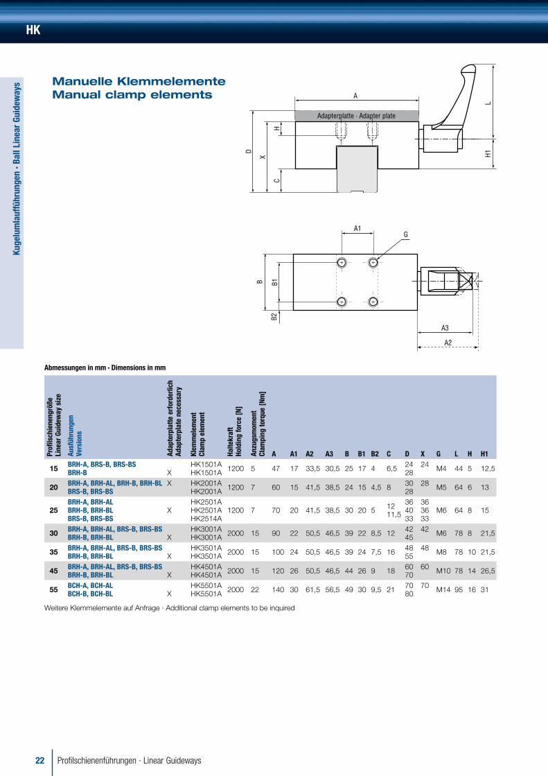
HK
Manuelle Klemmelemente Manual clamp elements
Abmessungen in mm · Dimensions in mm
Profi
lsch
iene
n grö
ße
Line
ar G
uide
way
siz
e
Ausf
ühru
ngen
Ve
rsio
ns
Adap
terp
latte
erf
orde
rlich
Ad
apte
rpla
te n
eces
sary
Klem
mel
emen
t Cl
amp
elem
ent
Halte
kraf
t Ho
ldin
g fo
rce
[N]
Anzu
gsm
omen
t Cl
ampi
ng to
rque
[Nm
]
A A1 A2 A3 B B1 B2 C D X G L H H1
15 BRH-A, BRS-B, BRS-BS BRH-B
X
HK1501A HK1501A 1200 5 47 17 33,5 30,5 25 17 4 6,5 24
2824 M4 44 5 12,5
20 BRH-A, BRH-AL, BRH-B, BRH-BL BRS-B, BRS-BS
X HK2001A HK2001A 1200 7 60 15 41,5 38,5 24 15 4,5 8 30
2828 M5 64 6 13
25BRH-A, BRH-AL BRH-B, BRH-BL BRS-B, BRS-BS
XHK2501A HK2501A HK2514A
1200 7 70 20 41,5 38,5 30 20 5 12 11,5
36 40 33
3636 33
M6 64 8 15
30 BRH-A, BRH-AL, BRS-B, BRS-BS BRH-B, BRH-BL X
HK3001A HK3001A 2000 15 90 22 50,5 46,5 39 22 8,5 12 42
4542 M6 78 8 21,5
35 BRH-A, BRH-AL, BRS-B, BRS-BS BRH-B, BRH-BL
X
HK3501A HK3501A 2000 15 100 24 50,5 46,5 39 24 7,5 16 48
5548 M8 78 10 21,5
45 BRH-A, BRH-AL, BRS-B, BRS-BS BRH-B, BRH-BL
X
HK4501A HK4501A 2000 15 120 26 50,5 46,5 44 26 9 18 60
7060 M10 78 14 26,5
55 BCH-A, BCH-AL BCH-B, BCH-BL
X
HK5501A HK5501A 2000 22 140 30 61,5 56,5 49 30 9,5 21 70
8070 M14 95 16 31
Weitere Klemmelemente auf Anfrage · Additional clamp elements to be inquired
D
X
CH
A1G
B B1B2
LH1
A3
A2
A
Adapterplatte · Adapter plate

23Profilschienenführungen · Linear Guideways
Rolle
num
lauf
führ
unge
n · R
olle
r Li
near
Gui
dew
ays
Rollenumlaufführungen Bestellschlüssel + Optionen Roller Linear Guideways Ordering code + Options
Rollenumlaufführungen verwenden Präzisionsrollen als Wälzkörper anstelle von Präzisionskugeln. Sie gewährleis-ten eine höhere Systemsteifigkeit, sowie höhere Lastauf-nahmefähigkeiten.
Roller Linear Guideways are equipped with precision rollers instead of balls. They provide higher rigidity and loadratings.
Profilschienen MSR-T – von unten montierbar Profilerails MSR-T – assembly from the bottom
AusführungVersion MxlMSR25T M6x12
MSR30T M8x15
MSR35T M8x17
MSR45T M12x24
MSR55T M14x24
MSR65T M20x30
Dichtungen Seals
ArtikelnummerModel No.
UU, SS, L4[mm] ZZ, L4[mm] UU, R [N]
MSR25 2 6 4,5
MSR30 2 7 8
MSR35 2 7 12
MSR45 1,6 7 18
MSR55 0,8 7,8 20
MSR65 0,8 7,8 35
L4: zusätzliche Länge des Laufwagens additional length of the carriage
R: zusätzlicher Verschiebewiderstand additional frictional resistance
Schmierung · Lubrication: Siehe Seite 7 · See page 7
Optionen · Options
Für weitere technische Informationen siehe Seite 10-12 · For further technical information please refer to pages 10-12
Beispiel · Sample: MSR-55 -E -2 -R-1260 -30-30 -P-CC-II
MSR 1. Ausführung
Type
55 2. Größe
Size
E 3. Bauart
Version
E mit Flansch with flange
LE lang, mit Flansch long, with flange
S ohne Flansch without flange
LS lang, ohne Flansch long, without flange
2 4. Anzahl der Laufwagen
pro Schiene Number of carriages per rail
SS 5. Ausführung der Dichtung
Sealversion
UU beidseitige Dichtung seals on both ends
SS Rundumdichtung allaround seal
ZZ SS + Metallabstreifer SS + metalscraper
LL reibungsarme beidseitige Dichtung low friction end seal
F2 6. Vorspannungsklasse
Preload grade
R 7. Schienenausführung
Railversion
R Durchgangsbohrung throughhole
T Sackbohrung von unten tapped hole type from the bottom
1260 8. Schienenlänge
Rail length
30-30 9. erster-letzter Lochabstand
distance of first-last hole
30-30 erster - letzter Lochabstand distance of first and last hole
P 10. Genauigkeit
Accuracy
CC 11. Schmutzschutz
Schiene Dustprotection of rail
II 12. Sets pro Achse
Sets per axis
L
M

24 Profilschienenführungen · Linear Guideways
Rolle
num
lauf
führ
unge
n · R
olle
r Li
near
Gui
dew
ays
Rollenumlaufführung Technische Eigenschaften Roller Linear Guideways Technical properties
GeschliffeneAnschlagkanteGrindingsurface
CD
A WB
H
CD
A WB
H
GeschliffeneAnschlagkanteGrindingsurface
Genauigkeitsklasse Accuracy class
Einheit · Unit: mm
Größe Size
Ausführung Item
Normal (N) Normal
Hoch (H) High
Präzision (P) Precision
Superpräzision (SP) Superprecision
Ultrapräzision (UP) Ultraprecision
15/20 Höhen- (H), Breitentoleranz (W) Tolerance of height (H), width (W) ±0,1 ±0,03 0/-0,03 0/-0,015 0/-0,008
15/20 Höhen- (H)1, Breitenunterschied (W)1
Height- (H)1, Width-difference (W)1 0,02 0,01 0,006 0,004 0,003
25/30/35 Höhen- (H), Breitentoleranz (W) Tolerance of height (H), width (W) ±0,1 ±0,04 0/-0,04 0/-0,02 0/-0,01
25/30/35 Höhen- (H)1, Breitenunterschied (W)1
Height- (H)1, Width-difference (W)10,02 0,03
0,015 0,015
0,007 0,007
0,005 0,005
0,003 0,003
45/55 Höhen- (H), Breitentoleranz (W) Tolerance of height (H), width (W) ±0,1 ±0,05 0/-0,05 0/-0,03 0/-0,02
45/55 Höhen- (H)1, Breitenunterschied (W)1
Height- (H)1, Width-difference (W)10,03 0,03
0,015 0,02
0,007 0,01
0,005 0,007
0,003 0,005
65 Höhen- (H), Breitentoleranz (W) Tolerance of height (H), width (W) ±0,1 ±0,07 0/-0,07 0/-0,05 0/-0,03
65 Höhen- (H)1, Breitenunterschied (W)1
Height- (H)1, Width-difference (W)10,02 0,03
0,02 0,025
0,01 0,015
0,007 0,01
0,005 0,007
1 Unterschied zwischen mehreren Führungswagen auf einer Schiene an derselben Position auf der Schiene 1 Difference between more than one carriage on the same rail at the same position of the rail
Schienenlänge und Parallelitätsabweichung Rail length and running parallelism
Vorspannungsklasse · Preload grade classC : Dynamische Tragzahlen · Basic dynamic load rating
Vorspannungsklasse ∙ Item Grade Symbol Vorspannkraft ∙ Preload force
ohne Vorspannung ∙no preload FC 0,02 C
leichte Vorspannung ∙ light preload F0 0,05 C
mittlere Vorspannung ∙ medium preload F1 0,08 C
starke Vorspannung heavy preload F2 0,13 C
0
5
10
15
20
25
30
0 315 400 500 630 800 1000 1250 1600 2000
N
H
P
SP
UP
(µm)
Schienenlänge · Length of rail (mm)

25Profilschienenführungen · Linear Guideways
Rolle
num
lauf
führ
unge
n · R
olle
r Li
near
Gui
dew
ays
MSR…E / MSR…LE
Standardausführung mit Flansch Standardversion with flange
Abmessungen in mm · Dimensions in mm
System · Assembly Laufwagen · carriage Schmier-bohrung Oil hole
Schiene · railArtikelnr. Model No. H W W2 E L B × J M MQ × l L1 L2 L3 G T1 N W1 H1 F D × h × dMSR25E 36 70 23,5 4,8 97,5 57 × 45 40 M8 × 9,5 65,5 6,6 6,5 G-M6 M6 6 12 23 23,5 30 11 × 9 × 7
MSR25LE 36 70 23,5 4,8 115,5 57 × 45 40 M8 × 9,5 83,5 6,6 6,5 G-M6 M6 6 12 23 23,5 30 11 × 9 × 7
MSR30E 42 90 31 6 112,1 72 × 52 44 M10 × 10 75,6 8 7 G-M6 M6 7 12 28 27,5 40 14 × 12 × 9
MSR30LE 42 90 31 6 136 72 × 52 44 M10 × 10 99,5 8 7 G-M6 M6 7 12 28 27,5 40 14 × 12 × 9
MSR35E 48 100 33 6,5 125,3 82 × 62 52 M10 × 12 82,3 8 7 G-M6 M6 8 12 34 30,5 40 14 × 12 × 9
MSR35LE 48 100 33 6,5 154,4 82 × 62 52 M10 × 12 111,4 8 7 G-M6 M6 8 12 34 30,5 40 14 × 12 × 9
MSR45E 60 120 37,5 8 154,2 100 × 80 60 M12× 14,5 106,5 10 10 G-PT 1/8 M6 10 13,5 45 37 52,5 20 × 17 × 14
MSR45LE 60 120 37,5 8 189,7 100 × 80 60 M12× 14,5 142 10 10 G-PT 1/8 M6 10 13,5 45 37 52,5 20 × 17 × 14
MSR55E 70 140 43,5 10 185,4 116 × 95 70 M14× 17,5 129,5 12 7,95 G-PT 1/8 M6 11 13,5 53 43 60 23 × 20 × 16
MSR55LE 70 140 43,5 10 235,4 116 × 95 70 M14× 17,5 179,5 12 7,95 G-PT 1/8 M6 11 13,5 53 43 60 23 × 20 × 16
MSR65LE 90 170 53,5 12 302 142 × 110 82 M16× 19,5 230 15 15 G-PT 1/8 M6 16,5 13,5 63 52 75 26 × 22 × 18
BezugsmaßRef. Data (mm)
TragzahlenBasic Load Rating (N)
Statisches MomentStatic Moment (Nm)
GewichtWeight
Artikelnr. Model No. Lmax G
Dynamisch (C)Dynamic (C)
Statisch (C0)Static (C0) Mx My Mz
Laufwagen (Kg)Carriage (Kg)
Schiene (Kg/M)Rail (Kg/M)
MSR25E 4000 20 29600 63800 730 650 650 0,75 3,5
MSR25LE 4000 20 36300 82900 950 1080 1080 0,95 3,5
MSR30E 4000 20 42800 91900 1270 1090 1090 1,4 5
MSR30LE 4000 20 54000 124000 1750 1960 1960 1,72 5
MSR35E 4000 20 57900 123500 2090 1590 1590 1,95 7
MSR35LE 4000 20 73900 169000 2850 2940 2940 2,45 7
MSR45E 4000 22,5 92800 193800 4400 3280 3280 3,9 11,2
MSR45LE 4000 22,5 117200 261600 5940 5900 5900 4,5 11,2
MSR55E 2150 30 132800 270000 7330 5490 5490 6 15,6
MSR55LE 2150 30 172500 378000 10280 10600 10600 7,9 15,6
MSR65LE 2150 35 277000 624000 20020 22500 22500 17,6 22,4
M
H1
Mx
Mz
My
6-MQ JN
∅DT1
L2LL1 4-G
EW2 W1
WB
H
d
h
G F∅
L3
l

26 Profilschienenführungen · Linear Guideways
Rolle
num
lauf
führ
unge
n · R
olle
r Li
near
Gui
dew
ays
MSR…S / MSR…LS
Standardausführung ohne Flansch Standardversion without flange
Abmessungen in mm · Dimensions in mm
System · Assembly Laufwagen · carriage Schmier-bohrung Oil hole
Schiene · railArtikelnr. Model No. H W W2 E L B × J MQ × l L1 L2 L3 G T1 N W1 H1 F D × h × dMSR25S 40 48 12,5 4,8 97,5 35 × 35 M6 × 10,5 65,5 6,6 6,5 G-M6 M6 10 12 23 23,5 30 11 × 9 × 7
MSR25LS 40 48 12,5 4,8 115,5 35 × 50 M6 × 10,5 83,5 6,6 6,5 G-M6 M6 10 12 23 23,5 30 11 × 9 × 7
MSR30S 45 60 16 6 112,1 40 × 40 M8 × 12 75,6 8 7 G-M6 M6 10 12 28 27,5 40 14 × 12 × 9
MSR30LS 45 60 16 6 136 40 × 60 M8 × 12 99,5 8 7 G-M6 M6 10 12 28 27,5 40 14 × 12 × 9
MSR35S 55 70 18 6,5 125,3 50 × 50 M8 × 14 82,3 8 7 G-M6 M6 15 12 34 30,5 40 14 × 12 × 9
MSR35LS 55 70 18 6,5 154,4 50 × 72 M8 × 14 111,4 8 7 G-M6 M6 15 12 34 30,5 40 14 × 12 × 9
MSR45S 70 86 20,5 8 154,2 60 × 60 M10 × 19 106,5 10 10 G-PT 1/8 M6 20 13,5 45 37 52,5 20 × 17 × 14
MSR45LS 70 86 20,5 8 189,7 60 × 80 M10 × 19 142 10 10 G-PT 1/8 M6 20 13,5 45 37 52,5 20 × 17 × 14
MSR55S 80 100 23,5 10 185,4 75 × 75 M12 × 19 129,5 12 7,95 G-PT 1/8 M6 21 13,5 53 43 60 23 × 20 × 16
MSR55LS 80 100 23,5 10 235,4 75 × 95 M12 × 19 179,5 12 7,95 G-PT 1/8 M6 21 13,5 53 43 60 23 × 20 × 16
MSR65LS 90 126 31,5 12 302 76 × 120 M16 × 20 230 15 15 G-PT 1/8 M6 16,5 13,5 63 52 75 26 × 22 × 18
BezugsmaßRef. Data (mm)
TragzahlenBasic Load Rating (N)
Statisches MomentStatic Moment (Nm)
GewichtWeight
Artikelnr. Model No. Lmax G
Dynamisch (C)Dynamic (C)
Statisch (C0)Static (C0) Mx My Mz
Laufwagen (Kg)Carriage (Kg)
Schiene (Kg/M)Rail (Kg/M)
MSR25S 4000 20 29600 63800 730 650 650 0,65 3,5
MSR25LS 4000 20 36300 82900 950 1080 1080 0,85 3,5
MSR30S 4000 20 42800 91900 1270 1090 1090 1 5
MSR30LS 4000 20 54000 124000 1720 1960 1960 1,22 5
MSR35S 4000 20 57900 123500 2090 1590 1590 1,65 7
MSR35LS 4000 20 73900 169000 2850 2940 2940 2,15 7
MSR45S 4000 22,5 92800 193800 4400 3280 3280 3,2 11,2
MSR45LS 4000 22,5 117200 261600 5940 5900 5900 4,1 11,2
MSR55S 2150 30 132800 270000 7330 5490 5490 5,1 15,6
MSR55LS 2150 30 172500 378000 10260 10600 10600 7 15,6
MSR65LS 2150 35 277000 624000 20020 22500 22500 13,3 22,4
H
EW2 W1
WB
l
N
T1
L2 L1 4-GL
∅ D
∅dG
H1h
F
6-MQL3
JMx
Mz
My

27Profilschienenführungen · Linear Guideways
Kreu
zrol
lenf
ühru
ngen
· Cr
ossr
olle
rgui
des
m
G1
F1
n1xF1 G1
L
G
F
nxF G
H
W1
T
M
D1
S
W
S1
g
f1
nxf1 g
L
CD
B
Kreuzrollenführungen Cross roller guides KRFT
Kreuzrollenführungen zeichnen sich durch eine extrem kompakte Bauform aus. Selbst bei Verwendung von zwei parallel laufenden Schienen reduziert sich der zur Integration erforderliche Platz auf ein Minimum. Zudem überzeugen die Genauigkeit, Steifigkeit und die geringen Reibungswerte der Führungen.
One of the main characteristics of cross roller guideways is their extremely compact physical structure. Even if using two parallel rails, the required space is reduced to a minimum. Additional outstanding features are the accura-cy, stiffness and the low friction of the guides.
Abmessungen in mm · Dimensions in mm
Abmessungen in mmDimensions in mm Läufer ∙ Carriage Schiene ∙ rail
TragzahlenLoad ratings
Genauigkeit Accuarcy
Artikel-Nr.Part. No.
Hub Strokemax.
W ±0,1
M ±0,1 L B F nxF G S F1 n1xF1 D1 G1 T H W1 m S1 f1 nxf1 g
C [N]
C0 [N]
C [µm]
D [µm]
KRFT 1025 12 20 8 25 14 18 1x18 3,5 M2,6 10 1x10 4,1 7,5 7,5 4 6,6 M2 M2,6 7,5 2x7,5 5,0 290 280 2 4
KRFT 1035 18 20 8 35 14 28 1x28 3,5 M2,6 10 2x10 4,1 7,5 7,5 4 6,6 M2 M2,6 10 2x10 7,5 390 420 2 4
KRFT 1045 25 20 8 45 14 20 1x20 12,5 M2,6 10 3x10 4,1 7,5 7,5 4 6,6 M2 M2,6 10 3x10 7,5 570 700 2 5
KRFT 1055 32 20 8 55 14 30 1x30 12,5 M2,6 10 4x10 4,1 7,5 7,5 4 6,6 M2 M2,6 10 4x10 7,5 660 840 2 5
KRFT 1065 40 20 8 65 14 20 2x20 12,5 M2,6 10 5x10 4,1 7,5 7,5 4 6,6 M2 M2,6 10 5x10 7,5 740 980 2 5
KRFT 1075 45 20 8 75 14 30 1x30 22,5 M2,6 10 6x10 4,1 7,5 7,5 4 6,6 M2 M2,6 10 6x10 7,5 890 1300 2 5
KRFT 1085 50 20 8 85 14 30 2x30 12,5 M2,6 10 7x10 4,1 7,5 7,5 4 6,6 M2 M2,6 10 7x10 7,5 960 1400 2 5
KRFT 2035 18 30 12 35 22 28 1x28 3,5 M3 15 1x15 6 10 11,5 6 12 M2 M3 20 1x20 7,5 520 520 2 4
KRFT 2050 30 30 12 50 22 43 1x43 3,5 M3 15 2x15 6 10 11,5 6 12 M2 M3 15 2x15 10 700 780 2 4
KRFT 2065 40 30 12 65 22 30 1x30 17,5 M3 15 3x15 6 10 11,5 6 12 M2 M3 15 3x15 10 870 1000 2 5
KRFT 2080 50 30 12 80 22 45 1x45 17,5 M3 15 4x15 6 10 11,5 6 12 M2 M3 15 4x15 10 1000 1300 2 5
KRFT 2095 60 30 12 95 22 30 2x30 17,5 M3 15 5x15 6 10 11,5 6 12 M2 M3 15 5x15 10 1200 1600 2 5
KRFT 2110 70 30 12 110 22 45 1x45 32,5 M3 15 6x15 6 10 11,5 6 12 M2 M3 15 6x15 10 1500 2100 2 5
KRFT 2125 80 30 12 125 22 45 2x45 17,5 M3 15 7x15 6 10 11,5 6 12 M2 M3 15 7x15 10 1600 2300 2 5
KRFT 3055 30 40 16 55 30 40 1x40 7,5 M4 25 1x25 7,5 15 15,5 8 16 M2 M4 35 1x35 10 1300 1400 2 5
KRFT 3080 45 40 16 80 30 65 1x65 7,5 M4 25 2x25 7,5 15 15,5 8 16 M2 M4 25 2x25 15 2200 2900 2 5
KRFT 3105 60 40 16 105 30 50 1x50 27,5 M4 25 3x25 7,5 15 15,5 8 16 M2 M4 25 3x25 15 3000 4300 3 6
KRFT 3130 75 40 16 130 30 75 1x75 27,5 M4 25 4x25 7,5 15 15,5 8 16 M2 M4 25 4x25 15 3700 5800 3 6
KRFT 3155 90 40 16 155 30 50 2x50 27,5 M4 25 5x25 7,5 15 15,5 8 16 M2 M4 25 5x25 15 4000 6500 3 6
KRFT 3180 105 40 16 180 30 75 1x75 52,5 M4 25 6x25 7,5 15 15,5 8 16 M2 M4 25 6x25 15 4100 6700 3 6
KRFT 3205 130 40 16 205 30 75 2x75 27,5 M4 25 7x25 7,5 15 15,5 8 16 M2 M4 25 7x25 15 4300 7300 3 6
Andere Größen/Sonderabmessungen auf AnfrageSpecials to be inquired
28 Profilschienenführungen · Linear Guideways
Kreu
zrol
lenf
ühru
ngen
· Cr
ossr
olle
rgui
des
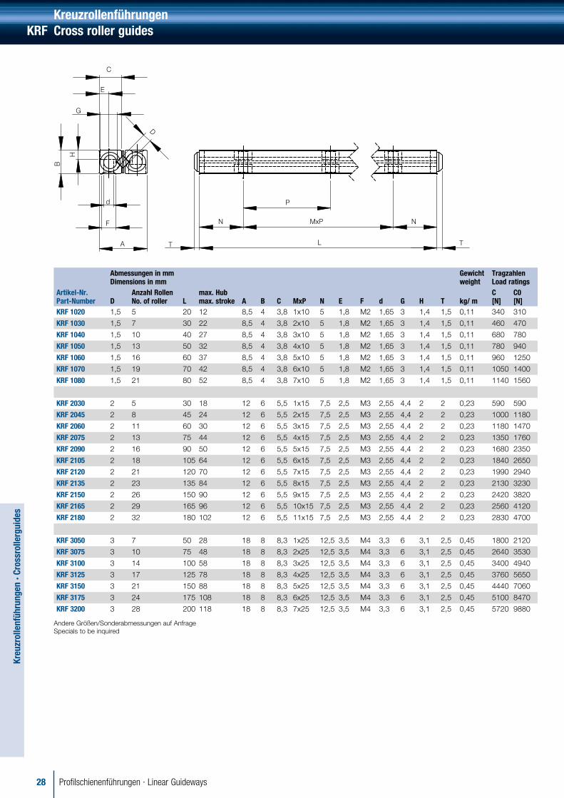
KreuzrollenführungenKRF Cross roller guides
E
D
G
C
d
H
B
A
F N
P
MxP N
LT T
Abmessungen in mmDimensions in mm
Gewichtweight
TragzahlenLoad ratings
Artikel-Nr.Part-Number D
Anzahl RollenNo. of roller L
max. Hubmax. stroke A B C MxP N E F d G H T kg/ m
C [N]
C0[N]
KRF 1020 1,5 5 20 12 8,5 4 3,8 1x10 5 1,8 M2 1,65 3 1,4 1,5 0,11 340 310
KRF 1030 1,5 7 30 22 8,5 4 3,8 2x10 5 1,8 M2 1,65 3 1,4 1,5 0,11 460 470
KRF 1040 1,5 10 40 27 8,5 4 3,8 3x10 5 1,8 M2 1,65 3 1,4 1,5 0,11 680 780
KRF 1050 1,5 13 50 32 8,5 4 3,8 4x10 5 1,8 M2 1,65 3 1,4 1,5 0,11 780 940
KRF 1060 1,5 16 60 37 8,5 4 3,8 5x10 5 1,8 M2 1,65 3 1,4 1,5 0,11 960 1250
KRF 1070 1,5 19 70 42 8,5 4 3,8 6x10 5 1,8 M2 1,65 3 1,4 1,5 0,11 1050 1400
KRF 1080 1,5 21 80 52 8,5 4 3,8 7x10 5 1,8 M2 1,65 3 1,4 1,5 0,11 1140 1560
KRF 2030 2 5 30 18 12 6 5,5 1x15 7,5 2,5 M3 2,55 4,4 2 2 0,23 590 590
KRF 2045 2 8 45 24 12 6 5,5 2x15 7,5 2,5 M3 2,55 4,4 2 2 0,23 1000 1180
KRF 2060 2 11 60 30 12 6 5,5 3x15 7,5 2,5 M3 2,55 4,4 2 2 0,23 1180 1470
KRF 2075 2 13 75 44 12 6 5,5 4x15 7,5 2,5 M3 2,55 4,4 2 2 0,23 1350 1760
KRF 2090 2 16 90 50 12 6 5,5 5x15 7,5 2,5 M3 2,55 4,4 2 2 0,23 1680 2350
KRF 2105 2 18 105 64 12 6 5,5 6x15 7,5 2,5 M3 2,55 4,4 2 2 0,23 1840 2650
KRF 2120 2 21 120 70 12 6 5,5 7x15 7,5 2,5 M3 2,55 4,4 2 2 0,23 1990 2940
KRF 2135 2 23 135 84 12 6 5,5 8x15 7,5 2,5 M3 2,55 4,4 2 2 0,23 2130 3230
KRF 2150 2 26 150 90 12 6 5,5 9x15 7,5 2,5 M3 2,55 4,4 2 2 0,23 2420 3820
KRF 2165 2 29 165 96 12 6 5,5 10x15 7,5 2,5 M3 2,55 4,4 2 2 0,23 2560 4120
KRF 2180 2 32 180 102 12 6 5,5 11x15 7,5 2,5 M3 2,55 4,4 2 2 0,23 2830 4700
KRF 3050 3 7 50 28 18 8 8,3 1x25 12,5 3,5 M4 3,3 6 3,1 2,5 0,45 1800 2120
KRF 3075 3 10 75 48 18 8 8,3 2x25 12,5 3,5 M4 3,3 6 3,1 2,5 0,45 2640 3530
KRF 3100 3 14 100 58 18 8 8,3 3x25 12,5 3,5 M4 3,3 6 3,1 2,5 0,45 3400 4940
KRF 3125 3 17 125 78 18 8 8,3 4x25 12,5 3,5 M4 3,3 6 3,1 2,5 0,45 3760 5650
KRF 3150 3 21 150 88 18 8 8,3 5x25 12,5 3,5 M4 3,3 6 3,1 2,5 0,45 4440 7060
KRF 3175 3 24 175 108 18 8 8,3 6x25 12,5 3,5 M4 3,3 6 3,1 2,5 0,45 5100 8470
KRF 3200 3 28 200 118 18 8 8,3 7x25 12,5 3,5 M4 3,3 6 3,1 2,5 0,45 5720 9880
Andere Größen/Sonderabmessungen auf Anfrage Specials to be inquired

29Profilschienenführungen · Linear Guideways
Kreu
zrol
lenf
ühru
ngen
· Cr
ossr
olle
rgui
des
Kreuzrollenführungen Cross roller guides KRF
Abmessungen in mmDimensions in mm
Gewichtweight
TragzahlenLoad ratings
Artikel-Nr.Part-Number
D Anzahl RollenNo. of roller
L max. Hubmax. stroke
A B C MxP N E F d G H T kg/ m C[N]
C0[N]
KRF 3225 3 31 225 138 18 8 8,3 8x25 12,5 3,5 M4 3,3 6 3,1 2,5 0,45 6020 10600
KRF 3250 3 35 250 148 18 8 8,3 9x25 12,5 3,5 M4 3,3 6 3,1 2,5 0,45 6620 12000
KRF 3275 3 38 275 168 18 8 8,3 10x25 12,5 3,5 M4 3,3 6 3,1 2,5 0,45 7190 13400
KRF 3300 3 42 300 178 18 8 8,3 11x25 12,5 3,5 M4 3,3 6 3,1 2,5 0,45 7750 14800
KRF 3325 3 45 325 198 18 8 8,3 12x25 12,5 3,5 M4 3,3 6 3,1 2,5 0,45 8030 15500
KRF 3350 3 49 350 208 18 8 8,3 13x25 12,5 3,5 M4 3,3 6 3,1 2,5 0,45 8570 16900
KRF 4080 4 7 80 58 22 11 10,2 1x40 20 4,5 M5 4,3 8 4,2 2,5 0,8 3560 4350
KRF 4120 4 11 120 82 22 11 10,2 2x40 20 4,5 M5 4,3 8 4,2 2,5 0,8 5220 7250
KRF 4160 4 15 160 106 22 11 10,2 3x40 20 4,5 M5 4,3 8 4,2 2,5 0,8 6720 10200
KRF 4200 4 19 200 130 22 11 10,2 4x40 20 4,5 M5 4,3 8 4,2 2,5 0,8 8120 13100
KRF 4240 4 23 240 154 22 11 10,2 5x40 20 4,5 M5 4,3 8 4,2 2,5 0,8 9430 16000
KRF 4280 4 27 280 178 22 11 10,2 6x40 20 4,5 M5 4,3 8 4,2 2,5 0,8 10700 18900
KRF 4320 4 31 320 202 22 11 10,2 7x40 20 4,5 M5 4,3 8 4,2 2,5 0,8 11900 21800
KRF 4360 4 35 360 226 22 11 10,2 8x40 20 4,5 M5 4,3 8 4,2 2,5 0,8 13100 24700
KRF 4400 4 39 400 250 22 11 10,2 9x40 20 4,5 M5 4,3 8 4,2 2,5 0,8 14200 27600
KRF 4440 4 43 440 274 22 11 10,2 10x40 20 4,5 M5 4,3 8 4,2 2,5 0,8 15300 30500
KRF 4480 4 47 480 298 22 11 10,2 11x40 20 4,5 M5 4,3 8 4,2 2,5 0,8 16400 33400
KRF 6100 6 7 100 56 31 15 14,2 1x50 25 6 M6 5,2 9,5 5,2 3 1,5 8870 11100
KRF 6150 6 10 150 96 31 15 14,2 2x50 25 6 M6 5,2 9,5 5,2 3 1,5 13020 18500
KRF 6200 6 13 200 136 31 15 14,2 3x50 25 6 M6 5,2 9,5 5,2 3 1,5 14920 22200
KRF 6250 6 17 250 156 31 15 14,2 4x50 25 6 M6 5,2 9,5 5,2 3 1,5 18520 29600
KRF 6300 6 20 300 196 31 15 14,2 5x50 25 6 M6 5,2 9,5 5,2 3 1,5 21890 37000
KRF 6350 6 24 350 216 31 15 14,2 6x50 25 6 M6 5,2 9,5 5,2 3 1,5 25100 44400
KRF 6400 6 27 400 256 31 15 14,2 7x50 25 6 M6 5,2 9,5 5,2 3 1,5 26650 48100
KRF 6450 6 31 450 276 31 15 14,2 8x50 25 6 M6 5,2 9,5 5,2 3 1,5 29680 55500
KRF 6500 6 34 500 316 31 15 14,2 9x50 25 6 M6 5,2 9,5 5,2 3 1,5 32600 62900
KRF 6600 6 41 600 376 31 15 14,2 11x50 25 6 M6 5,2 9,5 5,2 3 1,5 36820 74000
KRF 9200 9 10 200 118 44 22 20,2 1x100 50 9(8) M8 6,8 10,5 6,2 4 3,2 25300 36300
KRF 9300 9 15 300 178 44 22 20,2 2x100 50 9(8) M8 6,8 10,5 6,2 4 3,2 32500 50800
KRF 9400 9 20 400 238 44 22 20,2 3x100 50 9(8) M8 6,8 10,5 6,2 4 3,2 42500 72600
KRF 9500 9 25 500 298 44 22 20,2 4x100 50 9(8) M8 6,8 10,5 6,2 4 3,2 48700 87100
KRF 9600 9 30 600 358 44 22 20,2 5x100 50 9(8) M8 6,8 10,5 6,2 4 3,2 57600 109000
KRF 9700 9 35 700 418 44 22 20,2 6x100 50 9(8) M8 6,8 10,5 6,2 4 3,2 63600 123000
KRF 9800 9 40 800 478 44 22 20,2 7x100 50 9(8) M8 6,8 10,5 6,2 4 3,2 71500 145000
KRF 9900 9 45 900 538 44 22 20,2 8x100 50 9(8) M8 6,8 10,5 6,2 4 3,2 76800 160000
KRF 91000 9 50 1000 598 44 22 20,2 9x100 50 9(8) M8 6,8 10,5 6,2 4 3,2 84500 182000
30 Profilschienenführungen · Linear Guideways
Kreu
zrol
lenf
ühru
ngen
· Cr
ossr
olle
rgui
des
C
D
L
B
G2 G2
G1 n1xF1 G1
G nxF G
S
m1
g f1 g
f2
f4
f3
B2
m1
dxDxh
t1t2
TH
M
b1 b2W
S1xl
m2
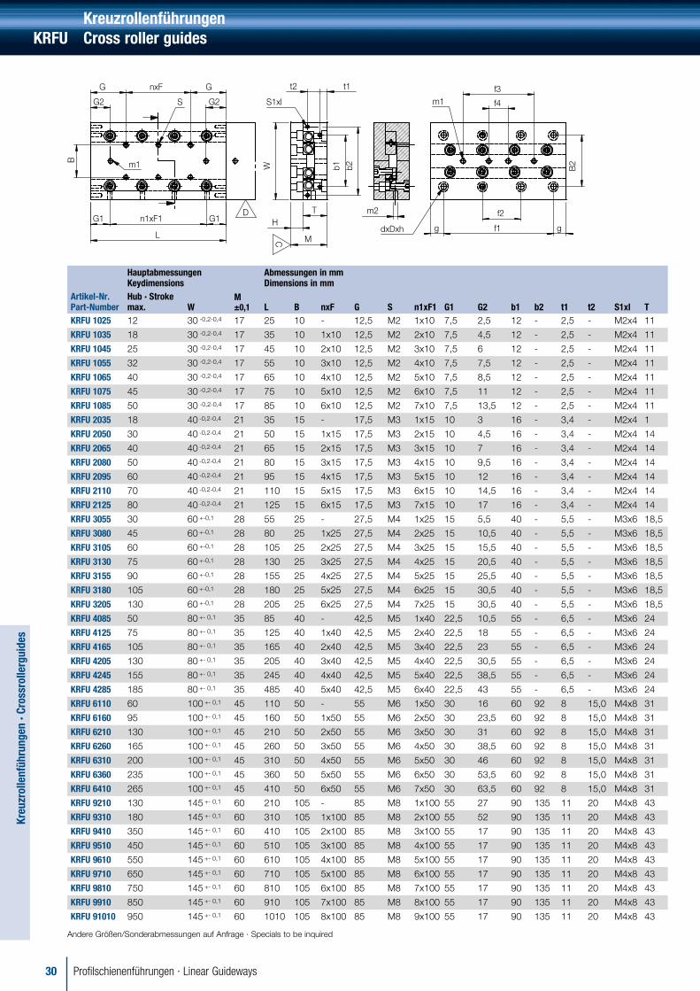
KreuzrollenführungenKRFU Cross roller guides
HauptabmessungenKeydimensions
Abmessungen in mmDimensions in mm
Artikel-Nr.Part-Number
Hub · Stroke max. W
M±0,1 L B nxF G S n1xF1 G1 G2 b1 b2 t1 t2 S1xl T
KRFU 1025 12 30 -0,2-0,4 17 25 10 - 12,5 M2 1x10 7,5 2,5 12 - 2,5 - M2x4 11
KRFU 1035 18 30 -0,2-0,4 17 35 10 1x10 12,5 M2 2x10 7,5 4,5 12 - 2,5 - M2x4 11
KRFU 1045 25 30 -0,2-0,4 17 45 10 2x10 12,5 M2 3x10 7,5 6 12 - 2,5 - M2x4 11
KRFU 1055 32 30 -0,2-0,4 17 55 10 3x10 12,5 M2 4x10 7,5 7,5 12 - 2,5 - M2x4 11
KRFU 1065 40 30 -0,2-0,4 17 65 10 4x10 12,5 M2 5x10 7,5 8,5 12 - 2,5 - M2x4 11
KRFU 1075 45 30 -0,2-0,4 17 75 10 5x10 12,5 M2 6x10 7,5 11 12 - 2,5 - M2x4 11
KRFU 1085 50 30 -0,2-0,4 17 85 10 6x10 12,5 M2 7x10 7,5 13,5 12 - 2,5 - M2x4 11
KRFU 2035 18 40 -0,2-0,4 21 35 15 - 17,5 M3 1x15 10 3 16 - 3,4 - M2x4 1
KRFU 2050 30 40 -0,2-0,4 21 50 15 1x15 17,5 M3 2x15 10 4,5 16 - 3,4 - M2x4 14
KRFU 2065 40 40 -0,2-0,4 21 65 15 2x15 17,5 M3 3x15 10 7 16 - 3,4 - M2x4 14
KRFU 2080 50 40 -0,2-0,4 21 80 15 3x15 17,5 M3 4x15 10 9,5 16 - 3,4 - M2x4 14
KRFU 2095 60 40 -0,2-0,4 21 95 15 4x15 17,5 M3 5x15 10 12 16 - 3,4 - M2x4 14
KRFU 2110 70 40 -0,2-0,4 21 110 15 5x15 17,5 M3 6x15 10 14,5 16 - 3,4 - M2x4 14
KRFU 2125 80 40 -0,2-0,4 21 125 15 6x15 17,5 M3 7x15 10 17 16 - 3,4 - M2x4 14
KRFU 3055 30 60 +-0,1 28 55 25 - 27,5 M4 1x25 15 5,5 40 - 5,5 - M3x6 18,5
KRFU 3080 45 60 +-0,1 28 80 25 1x25 27,5 M4 2x25 15 10,5 40 - 5,5 - M3x6 18,5
KRFU 3105 60 60 +-0,1 28 105 25 2x25 27,5 M4 3x25 15 15,5 40 - 5,5 - M3x6 18,5
KRFU 3130 75 60 +-0,1 28 130 25 3x25 27,5 M4 4x25 15 20,5 40 - 5,5 - M3x6 18,5
KRFU 3155 90 60 +-0,1 28 155 25 4x25 27,5 M4 5x25 15 25,5 40 - 5,5 - M3x6 18,5
KRFU 3180 105 60 +-0,1 28 180 25 5x25 27,5 M4 6x25 15 30,5 40 - 5,5 - M3x6 18,5
KRFU 3205 130 60 +-0,1 28 205 25 6x25 27,5 M4 7x25 15 30,5 40 - 5,5 - M3x6 18,5
KRFU 4085 50 80 +- 0,1 35 85 40 - 42,5 M5 1x40 22,5 10,5 55 - 6,5 - M3x6 24
KRFU 4125 75 80 +- 0,1 35 125 40 1x40 42,5 M5 2x40 22,5 18 55 - 6,5 - M3x6 24
KRFU 4165 105 80 +- 0,1 35 165 40 2x40 42,5 M5 3x40 22,5 23 55 - 6,5 - M3x6 24
KRFU 4205 130 80 +- 0,1 35 205 40 3x40 42,5 M5 4x40 22,5 30,5 55 - 6,5 - M3x6 24
KRFU 4245 155 80 +- 0,1 35 245 40 4x40 42,5 M5 5x40 22,5 38,5 55 - 6,5 - M3x6 24
KRFU 4285 185 80 +- 0,1 35 485 40 5x40 42,5 M5 6x40 22,5 43 55 - 6,5 - M3x6 24
KRFU 6110 60 100 +- 0,1 45 110 50 - 55 M6 1x50 30 16 60 92 8 15,0 M4x8 31
KRFU 6160 95 100 +- 0,1 45 160 50 1x50 55 M6 2x50 30 23,5 60 92 8 15,0 M4x8 31
KRFU 6210 130 100 +- 0,1 45 210 50 2x50 55 M6 3x50 30 31 60 92 8 15,0 M4x8 31
KRFU 6260 165 100 +- 0,1 45 260 50 3x50 55 M6 4x50 30 38,5 60 92 8 15,0 M4x8 31
KRFU 6310 200 100 +- 0,1 45 310 50 4x50 55 M6 5x50 30 46 60 92 8 15,0 M4x8 31
KRFU 6360 235 100 +- 0,1 45 360 50 5x50 55 M6 6x50 30 53,5 60 92 8 15,0 M4x8 31
KRFU 6410 265 100 +- 0,1 45 410 50 6x50 55 M6 7x50 30 63,5 60 92 8 15,0 M4x8 31
KRFU 9210 130 145 +- 0,1 60 210 105 - 85 M8 1x100 55 27 90 135 11 20 M4x8 43
KRFU 9310 180 145 +- 0,1 60 310 105 1x100 85 M8 2x100 55 52 90 135 11 20 M4x8 43
KRFU 9410 350 145 +- 0,1 60 410 105 2x100 85 M8 3x100 55 17 90 135 11 20 M4x8 43
KRFU 9510 450 145 +- 0,1 60 510 105 3x100 85 M8 4x100 55 17 90 135 11 20 M4x8 43
KRFU 9610 550 145 +- 0,1 60 610 105 4x100 85 M8 5x100 55 17 90 135 11 20 M4x8 43
KRFU 9710 650 145 +- 0,1 60 710 105 5x100 85 M8 6x100 55 17 90 135 11 20 M4x8 43
KRFU 9810 750 145 +- 0,1 60 810 105 6x100 85 M8 7x100 55 17 90 135 11 20 M4x8 43
KRFU 9910 850 145 +- 0,1 60 910 105 7x100 85 M8 8x100 55 17 90 135 11 20 M4x8 43
KRFU 91010 950 145 +- 0,1 60 1010 105 8x100 85 M8 9x100 55 17 90 135 11 20 M4x8 43
Andere Größen/Sonderabmessungen auf Anfrage · Specials to be inquired

Profilschienenführungen · Linear Guideways 31
Kreu
zrol
lenf
ühru
ngen
· Cr
oss
rolle
r gu
ides
Kreuzrollenführungen Cross roller guides KRFU
Abmessungen in mmDimensions in mm
TragzahlenLoad ratings
GenauigkeitAccuarcy
Artikel-Nr. Part-Number H dxDxh D1 m1 m2 B2 f1 f2 f3 f4 g C [N] C0 [N] C [µm] DKRFU 1025 5,5 2,55x4,1x2,5 4,1 M2 M2 22 18 - - - 3,5 290 280 2 4
KRFU 1035 5,5 2,55x4,1x2,5 4,1 M2 M2 22 28 - - - 3,5 390 420 2 4
KRFU 1045 5,5 2,55x4,1x2,5 4,1 M2 M2 22 38 - - - 3,5 570 700 2 5
KRFU 1055 5,5 2,55x4,1x2,5 4,1 M2 M2 22 48 28 - - 3,5 660 840 2 5
KRFU 1065 5,5 2,55x4,1x2,5 4,1 M2 M2 22 58 38 - - 3,5 740 980 2 5
KRFU 1075 5,5 2,55x4,1x2,5 4,1 M2 M2 22 68 48 - - 3,5 890 1300 2 5
KRFU 1085 5,5 2,55x4,1x2,5 4,1 M2 M2 22 78 58 - - 3,5 960 1400 2 5
KRFU 2035 6,5 3,5x6x3,5 6,0 M3 M3 30 25 - - - 5 520 520 2 4
KRFU 2050 6,5 3,5x6x3,5 6,0 M3 M3 30 40 - - - 5 700 780 2 4
KRFU 2065 6,5 3,5x6x3,5 6,0 M3 M3 30 55 - - - 5 870 1000 2 5
KRFU 2080 6,5 3,5x6x3,5 6,0 M3 M3 30 70 40 - - 5 1000 1300 2 5
KRFU 2095 6,5 3,5x6x3,5 6,0 M3 M3 30 85 55 - - 5 1200 1600 2 5
KRFU 2110 6,5 3,5x6x3,5 6,0 M3 M3 30 100 70 - - 5 1500 2100 2 6
KRFU 2125 6,5 3,5x6x3,5 6,0 M3 M3 30 115 85 - 5 1600 2300 2 6
KRFU 3055 9 4,5x7,5x5 7,5 M4 M4 40 35 - - - 10 1300 1400 2 5
KRFU 3080 9 4,5x7,5x5 7,5 M4 M4 40 60 - - - 10 2200 2900 2 5
KRFU 3105 9 4,5x7,5x5 7,5 M4 M4 40 85 - - - 10 3000 4300 3 6
KRFU 3130 9 4,5x7,5x5 7,5 M4 M4 40 110 - - - 10 3700 5800 3 6
KRFU 3155 9 4,5x7,5x5 7,5 M4 M4 40 135 - 85 - 10 4000 6500 3 6
KRFU 3180 9 4,5x7,5x5 7,5 M4 M4 40 160 - 110 - 10 4100 6700 3 7
KRFU 3205 9 4,5x7,5x5 7,5 M4 M4 40 185 85 135 - 10 4300 7300 3 7
KRFU 4085 10,5 5,5x9,5x6 9,5 M4 M4 60 65 - - - 10 3600 4900 2 5
KRFU 4125 10,5 5,5x9,5x6 9,5 M4 M4 60 80 - - - 22,5 5300 8200 3 6
KRFU 4165 10,5 5,5x9,5x6 9,5 M4 M4 60 120 - - - 22,5 6900 11500 3 7
KRFU 4205 10,5 5,5x9,5x6 9,5 M4 M4 60 160 80 - - 22,5 8300 14800 3 7
KRFU 4245 10,5 5,5x9,5x6 9,5 M4 M4 60 200 120 - - 22,5 9600 18000 3 7
KRFU 4285 10,5 5,5x9,5x6 9,5 M4 M4 60 240 160 - - 22,5 10900 21300 3 7
KRFU 6110 13 7x11x7 11 M5 M5 60 90 - - - 10 7600 10800 3 6
KRFU 6160 13 7x11x7 11 M5 M5 60 140 - - - 10 9500 14400 3 6
KRFU 6210 13 7x11x7 11 M5 M5 60 190 - 90 - 10 12800 21600 3 7
KRFU 6260 13 7x11x7 11 M5 M5 60 240 - 140 - 10 15900 28800 3 7
KRFU 6310 13 7x11x7 11 M5 M5 60 290 - 190 - 10 17400 32400 4 8
KRFU 6360 13 7x11x7 11 M5 M5 60 340 140 240 - 10 20200 39600 4 8
KRFU 6410 13 7x11x7 11 M5 M5 60 390 190 290 - 10 22900 46800 4 8
KRFU 9210 16 9x14x9 14 M8 M6 90 100 - - - 55 21300 35600 3 7
KRFU 9310 16 9x14x9 14 M8 M6 90 200 - - - 55 32500 62300 3 7
KRFU 9410 16 9x14x9 14 M8 M6 90 300 - 100 - 55 32500 62300 3 8
KRFU 9510 16 9x14x9 14 M8 M6 90 400 - 200 - 55 39200 80100 4 8
KRFU 9610 16 9x14x9 14 M8 M6 90 500 100 300 - 55 45600 97900 4 9
KRFU 9710 16 9x14x9 14 M8 M6 90 600 200 400 - 55 51600 116000 4 9
KRFU 9810 16 9x14x9 14 M8 M6 90 700 300 500 100 55 54600 125000 5 10
KRFU 9910 16 9x14x9 14 M8 M6 90 800 400 600 200 55 60300 142000 5 10
KRFU 91010 16 9x14x9 14 M8 M6 90 900 500 700 300 55 65900 160000 5 10
Andere Größen/Sonderabmessungen auf Anfrage · Specials to be inquired

32 Profilschienenführungen · Linear Guideways
Anwendungsspezifikationen · Application Specifications
Information zur Auslegung Ihrer individuellen Profilschienenführung Information to specify your individual Linear Guideway
RODRIGUEZ GmbH Precision in Motion Ernst-Abbe-Straße 20 52249 Eschweiler
T: +49 (0)2403 780-0 F: +49 (0)2403 780-860 [email protected] www.rodriguez.de
Firma / Company Name Datum / Date
Adresse / Address:
Ansprechpartner / Contact Name: Frau / Herr / Mrs. / Mr.
Funktion / Function
Tel. Fax
Mobil E-Mail
Angebotsdaten / Quotation Data
Anfragemenge / Quotation Quantity Stck. / Qty Losgröße / Lot size
Jahresbedarf / Annual requirement Stck./Jahr Pcs/Year
Gewünschter Liefertermin / Required Delivery
Wochen / Weeks Zielpreis / Target Price Je Stck. Per unit
Angebot bis / Proposal required Datum / Date
Anwendungsbeschreibung (bitte fügen Sie eine Zeichnung/Skizze bei) Application Description (please attach additional drawing or sketch)
Anwendung / Application
Welcher der folgende Punkte trifft zu? Which of the following applies?
Neuentwicklung / New application Ersatz für vorhandene Führung / Interchange for existing guideway
Besonderheiten / Other considerations
Basisinformation / Basic informationAnwendungsfall (Zutreffendes bitte ankreuzen) / Application (please mark with a cross)
W
S
ZF
YFXF
Xm
Zm
YA
ZA
Ym
MxMy
MzFx
FzFy
2
1
3
4
Z
Y Xm
S
ZF
YFXF
Xm
Zm
YA
ZA
Ym
MxMy
Mz
FxFz
Fy
2
1
Z
Y Xm
ZF
YFXF
Xm
Zm
YA
ZA
Ym
W
MxMy
Mz
FxFz
Fy
1
Z
Y Xm
2
ZF
YFXF
Xm
Zm
YA
ZA
Ym
MxMy
Mz
FxFz
Fy
1
Z
Y Xm

33Profilschienenführungen · Linear Guideways
Einbaulage (Zutreffendes bitte ankreuzen) / Mounting position (please mark with a cross)
Horizontal Wandmontage / Wall-mounting Vertikal / Vertical Systemdaten System Parameters
zA = [mm]
yA = [mm]
s = [mm]
w = [mm]
Masseschwerpunkt Center of Gravity
m = [kg]
xm = [mm]
ym = [mm]
zm = [mm]
Über Kopf / Upside down Drehung um X-Achse Rotation around x-axis
α
Drehung um Y-Achse Rotation around y-axis
α
Winkel / Angle
α = [°]
β = [°]
Bewegungsablauf / Movement
1. wirkende Bearbeitungskraft 1st acting processing force Phase 1 Phase 2 Phase 3 Phase 4 Phase 5 Phase 6
Fx [N]
Fy [N]
Fz [N]
xF [mm]
yF [mm]
zF [mm]
2. wirkende Bearbeitungskraft 2nd acting processing force Phase 1 Phase 2 Phase 3 Phase 4 Phase 5 Phase 6
Fx [N]
Fy [N]
Fz [N]
xF [mm]
yF [mm]
zF [mm]
direkt wirkende Momente directly acting torque Phase 1 Phase 2 Phase 3 Phase 4 Phase 5 Phase 6
Mx [Nm]
My [Nm]
Mz [Nm]
Translatorische Daten Motion data Phase 1 Phase 2 Phase 3 Phase 4 Phase 5 Phase 6
Beschleunigung a [m/s2] Acceleration a [m/s2]
Geschwindigkeit v [m/s] Velocity v [m/s]
Verzögerung a [m/s2] Deceleration a [m/s2]
Zeit t / Time t [s]
Weg s / Way s [mm]
Zeitanteil / Time slice [%]
Weganteil [%] Distance rate [%]
Betriebstemperatur / Operating temperature
max. __________°C min. __________°C
Betriebsbedingungen (z.B. Staub, Späne, Flüssigkeiten) / Special operating conditions (e.g. dust, chips, fluids)

34 Profilschienenführungen · Linear Guideways
Laufwagentyp / Carriage type
Baureihe / Series Vorspannung / Preload Class Genauigkeitsklasse / Accuracy Class
Miniaturführung / Low profile ball type
Kugelführung / Ball type
Rollenführung / Roller type
Spiel / Clearance ZF
Ohne Vorspannung / No preload Z0
Leichte Vorspannung / Light preload Z1
Mittlere Vorspannung / Medium preload Z1
Starke Vorspannung / Heavy preload Z3
N
H (Standard)
P
Schmierungsart / Lubrication Profilschienen-Ausführung / Rail type
Öl / Oil
Fett / Grease
Befestigung von oben / Mounting from top
Befestigung von unten / Mounting from bottom
Betriebszeiten / Operation time Geforderte Lebensdauer / Required lifetime
Zyklen/Stunde / Cycles/hour [z/h] 1-Schicht-Betrieb 1-shift-operating
2-Schicht-Betrieb 2-shift-operating
3-Schicht-Betrieb 3-shift-operating
in Zyklen / Cycles [z] Lz =
Arbeitstage/Jahr / Working days/year [d/y] in Kilometern / Kilometers [km] Lkm =
in Jahren / Years [y] Ly =
Skizze · Sketch
Sonstiges / Other notes

35Profilschienenführungen · Linear Guideways
Edelstahl & Polymer Gehäuseeinheiten Stainless Steel & Thermoplastic Bearing Housings
Dünnringlager Reali Slim Bearings
Kugelrollen Ball Units
Sonderlager Special Bearings
Linearkomponenten/-systeme/-motoren Linearcomponents/-systems/-motors
Präzisionslager Precision Bearings
Rodriguez® GmbH
RODRIGUEZ® erkannte sehr früh, dass auto-matisierte Bewegungsabläufe immer präzisere Komponenten erfordern. Die Schlüsselqualifikation ist die Kundenorientierung und damit die objektive Beratung, Forschung, Entwicklung und Fertigung. Nur wer die Details kennt – so glauben wir – kann komplexe Konstruktionslösungen schaffen.
Daher haben wir die Voraussetzungen für eine erfolgreiche Ingenieur-Beratung in allen Wälzlager-Fragen gemeinsam mit unseren Partnern in Theorie und Praxis erarbeitet.
Und: Praktizierte Kundennähe und hohe Flexibilität sind bei uns ebenso selbstverständlich wie ein bei-spielhafter Kundenservice.
RODRIGUEZ® has realised very quickly that auto-matic repetitive motions require for more and more precise components. Customer objective and sub-sequently the consulting, research, development and manufacturing is the key qualification. Our belief is that only those who know the details are able to pro-duce complex construction solutions. Therefore we have theoretically and practically elaborated the pre-conditions for a successful engineer consulting for all matters of roller bearings together with our partners.
And: Practised customer proximity and high flexibility are of course of the same value to us as a perfect customer service.

Vertrieb · Distribution
Deutschland / Germany
Zentrale und Fertigung Main Office and Production
RODRIGUEZ GmbH Ernst-Abbe-Str. 20 52249 EschweilerTel.: +49 (0)2403 780-0 Fax: +49 (0)2403 780-860 [email protected] www.rodriguez.de
Niederlassung Süd Office South Germany
RODRIGUEZ GmbH Max-Eyth-Str. 8 71672 Marbach a. Neckar Tel.: +49 (0)7144 8558-0 Fax: +49 (0)7144 8558-20 [email protected]
Frankreich / France
Rodriguez GmbH 29/31 Boulevard de la PaixParc d'activités du Bel Air78 100 Saint Germain En LayeTel.: +33 (0)130 610616Fax: +33 (0)130 [email protected]
USA
ICB Greenline 5808 Long Creek Park DriveSuite QCharlotte, NC 28269Tel.: (704) 333 3377 Fax: (704) 334 6146 [email protected] www.greenlineconveyor.com
Edelstahl & Polymer Gehäuseeinheiten Stainless Steel & Thermoplastic Bearing Housings
Dünnringlager Reali Slim Bearings
Kugelrollen Ball Units
Sonderlager Special Bearings
Linearkomponenten/-systeme/-motoren Linearcomponents/-systems/-motors
Präzisionslager für Maschinenbau und Rundschalttische Precision Bearings for Machine Tools and Indexing Tables
Für die neuesten Veröffentlichungen – Kataloge, Software, oder CAD Zeichnungen – besuchen Sie unsere Website www.rodriguez.de For latest releases – newest features – and downloads of catalogs, software, or CAD drawings visit our website www.rodriguez.de
Dieser Katalog ist durch die RODRIGUEZ GmbH urheberrechtlich geschützt. Ohne schrift-liche Genehmigung der RODRIGUEZ GmbH dürfen weder Abschnitte noch der gesamte Katalog nachgedruckt oder reproduziert werden. Für technische Änderungen oder Irrtümer kann keine Haftung übernommen werden, für Hinweise bedanken wir uns. Alle bisherigen Ausgaben verlieren hiermit ihre Gültigkeit. We reserve the right to make technical changes. We take no responsibility for errors, but welcome comments. Reproduction either in part or in total, is prohibited. The validity of all previous editions have expired.© RODRIGUEZ LIN A4.6 2019 D/GB