ball screw power drive - agri ventilation … manual 151223.pdfdayton, virginia 22821 1-800-526-4188...
TRANSCRIPT

Dayton, Virginia 228211-800-526-4188
BALL SCREWPOWER DRIVE
VENTILATION SYSTEMOPERATORS MANUAL
Read This Entire Manual Prior To Installation. This Manual MustBe Given To And Reviewed By The Grower After The Unit HasBeen Installed. This Manual Should Be Kept In A Safe, Readily
Accessible Place For Quick Reference.
August 2008
1

GENERAL INFORMATIONSpecifications
Power Requirements
All Ball Screw Power Units require either 110-120 VAC or 230-240 VAC depending on the electric motor (installed at the factory) powering the drive. Be sure to check the motor voltage ratings when making electrical connections. The Control Circuit connections in the Motor Compartment enable an external Control Unit to control the opening and closing of the Power Unit. The relays in the Motor Compartment can be matched to a different Control Unit voltage to operate the Power Unit motor. The ElectricMotor and Relays are installed at the factory based on the costumer’s requirements.
The Ball Screw Power Unit is manufactured with an optional Power Fail feature. This feature enables curtains/inlets to drop automatically when electrical power is disabled. An external thermostat option provides a high-heat override also allowing curtains/inlets to drop automatically in high heat conditions.
DesignationBL Ball Screw Power Unit with Lovejoy Coupling.BP Ball Screw Power Unit with Power Fail Clutch Coupling.
-A 115 VAC Control Voltage-D 230 VAC Control Voltage-C 24 VAC Control Voltage
Motor Voltage and Speed: Rate of Travel:N 115 VAC, 107 RPM 53 inches per minute O 115 VAC, 40 RPM 20 inches per minuteP 115 VAC, 23 RPM 11 inches per minuteS 230 VAC, 107 RPM 53 inches per minuteR 230 VAC, 40 RPM 20 inches per minute
Model Unit Description Total Travel1800 18 Inch 15 inches3000 3 Foot 32 inches4000 4 Foot 45 inches5000 5 Foot 57 inches6000 6 Foot 68 inches
Dimensions: Length Length
Model Without Pulleys With Pulleys Width Depth 1800 39” 48” 9” 6” 3000 57” 63” 9” 6” 4000 69” 75” 9” 6” 5000 81” 87” 9” 6” 6000 93” 99” 9” 6”
2

INSTALLATIONThe Ball Screw Power Drive is capable of handling one or both sides of a curtain house, or all inlets of a static pressure house. All Ball Screw units are designed for ALL POSITION mounting. Units are to be installed by qualified personnel, and standard safety practices must be employed at all times.
There are various ways of installing power drive equipment: inside or outside the building, end wall, sidewall, ceiling, etc. The installer must evaluate the installation to suit the application. Other criteria to consider include: size and structure of building, weight of curtains and/or inlets, cabling and connections to the Power Drive, Power Driveplacement and orientation, and so on.
Inlet boards have other considerations in addition to the above. Inlets come in various weights and sizes, may be installed with weights and/or springs, etc. The installer must determine what is necessary to enable the inlets to open when the optional Power FailureBall Screw Power Drive is being used. Additional weights or springs may be necessary for the inlets, or a counter weight may be necessary to offset heavy inlet boards.
LIMIT SWITCH LEVER ARMS
Check the operation of the limit switches when installing. The limit switches are located in the motor compartment of the Ball Screw case, on the Electrical Plate. Changes in adjustment may have occurred due to shipping and handling. All limit switch arms should contact the lower portion of the plastic cam rod (see the illustration below) when the drive unit is between its end stops. The plastic cam may be adjusted by rotating it “up” or “down” the ¼ inch steel Control Rod using pliers. Check limit switch activation (“clicking” of the switch) by moving the Control Rod back and forth by hand. The limit switches should click when each switch lever arm is approximately halfway up or down the transition between the upper and lower portions of the plastic cam rod. It may be necessary to bend the limit switch lever arm to make adequate contact on the cam rod.
COMNO
NC
COMNO
NC
COMNO
NC
The two limit switches on the far side of the cam rod are the Primary switches. They should be at the edges of the lower portion of the cam rod. The third switch on the near side is the Fail-Safe switch. It should be midway between the higher portions of the cam rod. This switch will not activate when the Power Drive is functioning normally. It will function when a Primary limit switch fails, or if the Motor Brake does not stop the motor when the Pull Bar reaches the set collar limit stops. Both of these conditions will require servicing to restore proper operation.
3

POWER FAILURE CLUTCH
Upon installation, check the gap between the clutch and clutch disk on those units so equipped. Some shifting may have occurred in shipping. When the power is off, turn thescrew shaft by hand using a cloth or paper towel. There should be a minimal distance of 0.003” between the clutch and disk that will allow the disk to turn freely, with slight or norubbing between the two. There are 2 Allen/set screws on the clutch collar that must be loosened to adjust the clutch. See Diagram on P.18.
WINCHING PRECAUTIONS
DO NOT USE double back winching with the Ball Screw Power Drive unless approval is granted by the manufacturer. The performance and speed of the Ball Screw Power Drive eliminates the need for double back winching in most cases.
When integrating the Ball Screw Power Drive with an existing installation, all cables and pulleys should be examined to ensure ease of operation and adjustments made where necessary.
MOUNTING
CL OSE
OPEN
MAN UAL
AUTO
Ball Nut Travel Guides
2x10 Mounting Board
The recommended mounting method is to fasten the unit to a 2”x10”x12’ (or larger) pressure treated board. The Ball Screw Case has predrilled holes to simplify mounting. The unit may be mounted directly to the 2”x10” mounting board using 3/8”x2” hex head lag screws.
The drive unit may be directly mounted to the ceiling joists or wall studs. Measure center to center of the joists and transfer themeasurements to the back side of the Ball Screw unit housing. Drill ½” holes for mounting.
Caution!!! When drilling any mounting holes Do Not drill holes in the Ball Nut Guide Travel Path. Such holes and mounting screws will interfere with thetravel path of the Ball Nut Guides and adversely effect the Ball Screw operation.
4
REGULAR SERVICE
LUBRICATION
The Ball Screw shaft requires periodic attention: Apply a small bead of white lithium grease (included with Power Unit) on the length of the screw shaft about every three months.
The Pull Bar Guides may rub along some of its travel along the Ball Screw Case when load is applied to the unit. Apply a small amount of grease with a cloth or a finger to the case where rubbing occurs.
The Ball Screw Power Drive is equipped with a heavy duty thrust bearing, located in the coupling portion of the Ball Screw case. This bearing has been pre-greased at the factory,and will not require further greasing for approximately 24 months. To prevent over greasing, the grease fitting on the thrust bearing has been turned away from the opening of the Ball Screw case. Over greasing may lead to grease contamination on the clutch coupling (for those units so equipped), resulting in clutch slippage.
ADJUSTMENTS
Periodically check the set collar positions on the limit switch rod and tighten thumb screws and set screws.
Check the gap between the clutch and clutch disk on those units so equipped. When the power is off, turn the screw shaft by hand using a cloth or paper towel. There should be aminimal distance, less than 0.003”, between the clutch and disk that will allow the disk toturn freely, with minimal or no rubbing between the two. There are 2 Allen/set screws onthe collar of the clutch that can be loosened so that the clutch may be adjusted.
There are 2 basic types of motor brakes that are mounted on the end of the motor of the Ball Screw Drive. The Power On Brake has a Disk Collar fastened on the end of the motor shaft. With power off, the disk collar can be turned by hand: check that the two setscrews are tight, and that the gap between the disk and the electromagnet is not greater then 0.005 inches. The Power Off Brake has a Nut that is hidden by the electromagnet.
NOTE: Electrical components, clutches and brakes are energized at all times when theDrive Unit is powered. These become warm, even hot, to the touch under normaloperation. Power must be disconnected and components allowed to cool prior to
servicing in the electrical compartments.
5

BALL SCREW ILLUSTRATIONS AND ASSEMBLIES
SECTION PAGE
INSTALLATION ILLUSTRATIONS 7,8,9,10
BALL SCREW SHELL ASSEMBLY 11,12
1: PULLEY PLATE ASSEMBLY
5-1/4” Pulley Plate Assembly 13
Tri-Pulley Plate Assembly 14
2: BALL NUT AND THRUST PLATE 15
3: ROD ASSEMBLY
Control Rod Assembly for Power Failure Model 16
Control Rod Assembly for Lovejoy Model 17
4: CLUTCH AND COUPLING ASSEMBLY
Power Failure Clutch Assembly 18
Lovejoy Coupling Assembly 19
5. MOTOR ASSEMBLY
Motor/Plate Assembly 20
Power On Brake Assembly 21
Power Off Brake Assembly 22
6: ELECTRICAL ASSEMBLY 23
Electrical Plate Layout 24,25
Electrical Diagrams 26,27,28
SAMPLE CONTROL HOOK-UPS
TROUBLESHOOTING
6

Mounting Illustration #1
End Mount to Raise Curtainson Both Sides of Building.
Mount hand winch foreach wall of curtain.
Corner Bracket with Pulley Corner Bracket with Pulley
Cables should beadjusted so that pulleys are at least the length ofthe drive travelplus 1 foot away from the Ball Screwwhen fully retracted.
When cabling is complete,adjust lower and upper limitstops to match curtain height.
NOTE: On Power Failureunits the upper (open) stopis pre-set at the factory andshould not be changed.
Hand winch
One-to-one pulley and cable arrangement
CLOSE
OPEN
M ANUAL
AUTO
NOTE: LOAD ON PULL BAR MUST BE EVENLYDISTRIBUTED ON BOTH SIDES OF BALL SCREW SHAFT.
7

CL
OS
E
OP
EN
MA
NU
AL
AUT
O
to curtains
to curtains
to curtains
to curtains
hand winch
thru-wall pulleys
thru-wall pulleys
Mounting Illustration #2
Ceiling Mount in Center of Building to Raise Curtains on Both Sides of Building.
Distance from Drive Pulleys (whendrive unit is retracted) to first pulleys should equal the length of drive travel plus one foot.
One-to-one pulley and cable arrangement
NOTE: LOAD ON PULL BAR MUST BE EVENLYDISTRIBUTED ON BOTH SIDES OF BALL SCREW SHAFT.
8

Mounting Illustration #3
Exterior Mount, Middle of Side to Raise Curtains on Both Sides of Building.
Cables should beadjusted so that pulleys are at least the length ofthe drive travelplus 1 foot away from the Ball Screwwhen fully retracted.
When cabling is complete, adjustlower and upperlimit stops to match curtain height.
NOTE: On Power Failure units the upper (open) stop is pre-set at the factory and should not be changed.
One-to-one pulley and cable arrangement
C LOSE
OPEN
MANUAL
AUT O
Thru-wall pulleys andcables to other side of house.
NOTE: LOAD ON PULL BAR MUST BE EVENLY DISTRIBUTED ON BOTH SIDES OF BALL SCREW SHAFT.
Curtain
CurtainCurtain
Curtain
9

CLOSE
OPEN
MA NUAL
A UTO
L1L2/NTLGND
115/230 VAC SUPPLY
Ball Screw Power Failure Thermostat Override Connections
CL OSE
O PEN
M ANUAL
AUT O
Illustration #4Sample One-to-Two Pulley and Cable Arrangement
Illustration #5
NOTE: LOAD ON PULL BAR MUST BE EQUALLY DISTRIBUTED ON BOTH SIDES OF BALL SCREW SHAFT.
COM
N.C.
10
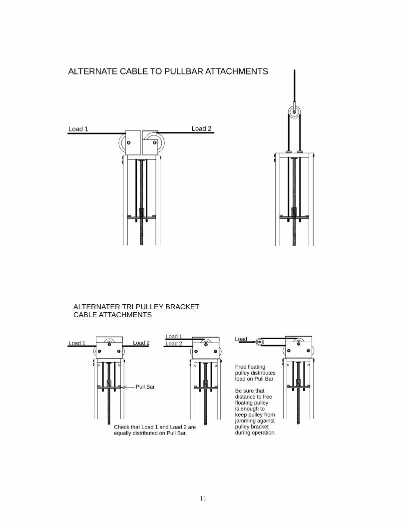
ALTERNATE CABLE TO PULLBAR ATTACHMENTS
Load 1 Load 2
ALTERNATER TRI PULLEY BRACKET CABLE ATTACHMENTS
Load 1 Load 2Load
Load 2Load 1
Check that Load 1 and Load 2 are equally distributed on Pull Bar.
Pull Bar
Free floatingpulley distributesload on Pull Bar
Be sure thatdistance to freefloating pulley is enough to keep pulley fromjamming againstpulley bracket during operation.
11

SECTION 1: PULLEY ASSEMBLIES
SECTION 2: BALLNUT AND THRUST ASSEMBLIES
SECTION 3: ROD ASSEMBLIES
SECTION 4: CLUTCH AND COUPLING ASSEMBLIES
SECTION 5: MOTOR ASSEMBLIES
SECTION 6: ELECTRICAL ASSEMBLIES
CLOSE
OPEN
MANUAL
AUTO
12

BALL SCREW SHELL ASSEMBLY
1. Lid (length or unit size- 3',4',5',or 6') HexHead Tek Screw SM-8-.5HHT (9 per lid)2. Pulley End Plate w/ stiffener (double plated) a. 5/16"x3/4" Bolt (BT-.312-.75G) (6 per plate) 5/16" Nut (NT-.312) (6 per plate)3. Chain Bracket (BS-CB-1000) (2 per unit) Power Failure models only4. Door Clasp-Latch & Hook (BS-LT-903B) (2 per unit) Pop Rivet (BSS42) (4 per clasp)
1 2
a
3
4
5
6
7
a
a
a
CASE/SHELL
a
5. Bearing Thrust Plate w/ stiffener (Double plated) a. 5/16"x3/4" Bolt (BT-.312-.75G) (6 per plate) 5/16" Nut (NT-.312) (6 per plate)6. Motor Plate a. 5/16"x3/4" Bolt (BT-.312-.75G) (4 per plate) 5/16" Nut (NT-.312) (4 per plate)7. End Plate a. 5/16"x3/4" Bolt (BT-.312-.75G) (4 per plate) 5/16" Nut (NT-.312) (4 per plate)
13

1. 1/2" Jam Nut (NT-.500J) (2 per pulley)2. "C" Bracket (2 per assembly)3. 3/4"x1 1/2" Hollow Bolt (BT-.750-1.5H) (1 per pulley)4. 1/2" Flat Washer (WA-.500S) (2 per pulley)
5 1/2' PULLEY PLATE ASSEMBLY
4
1
7
9
10
3
2
1
5
4
6
8
5. 5 1/4" Pulley w/ Grease Hub (1026) (2 per assembly)6. "L" Bracket (2 per assembly)7. Pulley End Plate w/ Stiffener8. Rod Bushing (BS-3001)9. 3/4" Jam Nut (NT-.750J) (2 per assembly)10. Pulley Bracket Assembly
14

TRI PULLEY PLATE ASSEMBLY
4
10
7
9
3
21
5
4
6
8
1. 1/2" Jam Nut (NT-.500J) (2 per pulley)2. Tri-pulley "C" Bracket3. 3/4"x1 1/2" Hollow Bolt (BT-.750-1.5H) (2 per assembly)4. 1/2" Flat Washer (WA-.500S) (2 per pulley)
5. 3" Pulley (1018) (3 per assembly)6. Tri pulley "L" Bracket7. Pulley End Plate w/ Stiffener8. Rod Bushing (BS-3001)9. 3/4" Jam Nut (NT-.750J) (2 per assembly)10. Pulley Spindle (HH-1004)
1
15

BALLNUT AND THRUST ASSEMBLY1
2a
3
4
5 66
7
1 23}
}
1 - 5/8" Stover Nut (LN-.625FS)2a - Bearing Washer (BS-TRB-1018)2b - Disc Bearing (BS-NTA-1018)2c - Bearing Washer (BS-TRC-1018)3 - Spring washers (6) (BS-Z-15)4 - Ballnut (BS-RF-0372)5 - Pullbar (Center Guide) (BS-3003)6 - Pullbar Guides (2) (BS-SGB-L & BS-SGB-R)7 - Ballscrew Rod (BS-3004)8 - Brush9 - Reducing Washer (HW-RW-0012)10 - 10/24" x 1/2" PHM screw (MS-1024-.5PHP)11 - 1/4 x 1-1/2 hexhead bolt (BT-.250-1.5G2)12 - 1/4" nut (NT-.250)13 - #8 Washer (WA-8)
8
910
11
12
2b2c
13
16
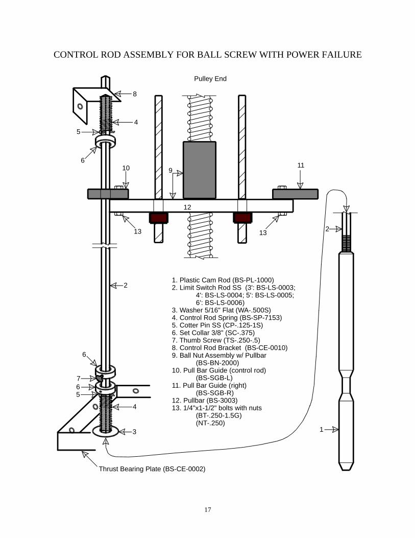
CONTROL ROD ASSEMBLY FOR BALL SCREW WITH POWER FAILURE
1
2
3
4
567
8
9
1. Plastic Cam Rod (BS-PL-1000)2. Limit Switch Rod SS (3': BS-LS-0003; 4': BS-LS-0004; 5': BS-LS-0005; 6': BS-LS-0006)3. Washer 5/16" Flat (WA-.500S)4. Control Rod Spring (BS-SP-7153)5. Cotter Pin SS (CP-.125-1S)6. Set Collar 3/8" (SC-.375)7. Thumb Screw (TS-.250-.5)8. Control Rod Bracket (BS-CE-0010)9. Ball Nut Assembly w/ Pullbar (BS-BN-2000)10. Pull Bar Guide (control rod) (BS-SGB-L)11. Pull Bar Guide (right) (BS-SGB-R)12. Pullbar (BS-3003)13. 1/4"x1-1/2" bolts with nuts (BT-.250-1.5G) (NT-.250)
Pulley End
Thrust Bearing Plate (BS-CE-0002)
10 11
12
13 13
6
6
54
2
17
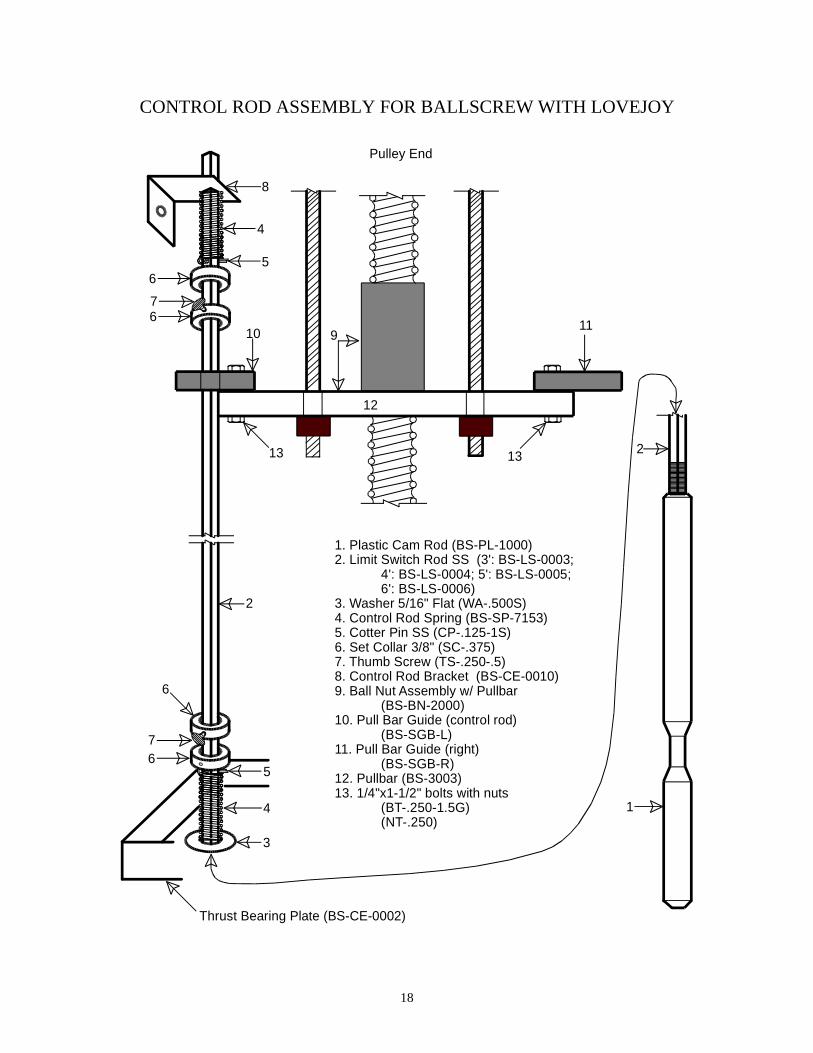
CONTROL ROD ASSEMBLY FOR BALLSCREW WITH LOVEJOY
1
2
3
4
5
6
7
8
1. Plastic Cam Rod (BS-PL-1000)2. Limit Switch Rod SS (3': BS-LS-0003; 4': BS-LS-0004; 5': BS-LS-0005; 6': BS-LS-0006)3. Washer 5/16" Flat (WA-.500S)4. Control Rod Spring (BS-SP-7153)5. Cotter Pin SS (CP-.125-1S)6. Set Collar 3/8" (SC-.375)7. Thumb Screw (TS-.250-.5)8. Control Rod Bracket (BS-CE-0010)9. Ball Nut Assembly w/ Pullbar (BS-BN-2000)10. Pull Bar Guide (control rod) (BS-SGB-L)11. Pull Bar Guide (right) (BS-SGB-R)12. Pullbar (BS-3003)13. 1/4"x1-1/2" bolts with nuts (BT-.250-1.5G) (NT-.250)
2
6
911
1313
12
10
5
4
76
6
Pulley End
Thrust Bearing Plate (BS-CE-0002)
18

BALLSCREW POWER FAIL MODELCLUTCH AND CENTRIFUGAL BRAKE ASSEMBLY
1
2
3
4
5
6
7
8
9
10
11
12
13
12
11
13
14a
b
1. Bolt 3/8x1-1/2" (BT-.375-1.5G)-2 2. Ball Screw Rod (BS-3004-x) 3. Bolt 3/8x3" (BT-.375-3.0G)-2 4. Bearing Plate (Double Plated) (BS-CE-0002) 5. Thrust Bearing 1-1/4" (BS-SCJ-114) 6. Brake Drum Spacer (BS-BR-1005)-2 7. Split Bushing-2 halves (BS-3002) 8. Centrifugal Brake Drum (BS-BR-1001) 9. Nut 3/8" (NT-.375)-410. Brake Shoe Spring (BS-36-0926)-311. Brake Arm (BS-BR-1003)-312. Hex Head Bolt 10/32x1/2" (HW-HX-1032)-613. Brake Shoe (BS-BR-1002)-314. Clutch Unit (includes a & b) a. Clutch Disk b. Clutch Electromagnet 90 VDC (BS-0717-1712) 190 VDC (BS-0717-0009)15. Clutch Restraining Bolt 8/32x1-1/2" (BT-.375-1.5G)16. Gearmotor Shaft17. 8/32 Nut (NT-832)18. Motor Plate (BS-CE-0004)19. Gearmotor (Check Voltage and RPM)20. Gearmoter Mounting Bolts 1/4"x1/2" (BT-.250-.5G2)-4
FAC
ES
IDE
8
17
1516
18
19
This gap should be 0.003 inch between the electromagnetand disc.
9
20
19

BALLSCREW LOVEJOY MODELLOVEJOY ASSEMBLY
1. Ball Screw Rod (BS-3004-x) 2. Nut 3/8" (NT-.375)-4 3. Bearing Plate (Double Plated) (BS-CE-0002) 4. Thrust Bearing 1-1/4" (BS-SCJ-114) 5. Bolt 3/8x1-1/2" (BT-.375-1.5G)-4 6. Split Bushing-2 halves (BS-3002) 7. 5/8" Lovejoy Coupling (DR-LJ-0000)-2 8. Urethane Spider (DR-LJ-000U) 9. Gearmotor Shaft10. Motor Plate (BS-CE-0004)11. Gearmotor (Check Voltage & RPM)12. Gearmotor Mounting Bolts 1/4"x1/2" (BT-.250-.5G2)
12
4
5
7
3
6
8
7
9 10
11
1212
20
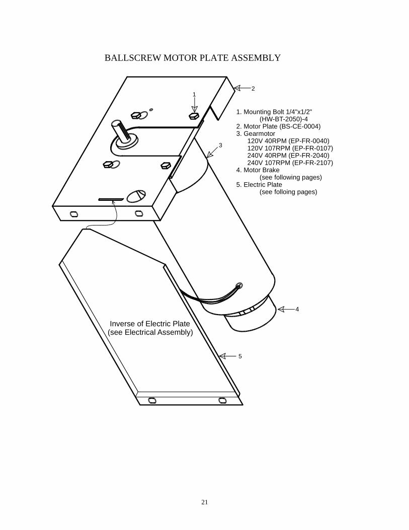
BALLSCREW MOTOR PLATE ASSEMBLY
Inverse of Electric Plate (see Electrical Assembly)
1. Mounting Bolt 1/4"x1/2" (HW-BT-2050)-42. Motor Plate (BS-CE-0004)3. Gearmotor 120V 40RPM (EP-FR-0040) 120V 107RPM (EP-FR-0107) 240V 40RPM (EP-FR-2040) 240V 107RPM (EP-FR-2107)4. Motor Brake (see following pages)5. Electric Plate (see folloing pages)
12
3
4
5
21

POWER ON BRAKE ASSEMBLY
1
2a
2b
3
4
1 - Gearmotor2a - Brake Electromagnet2b - Brake Disc 90 V - BS-1112-0021 190 V - BS-1112-00253 - 8/32" x 3/8" Machine Screw (4) (MS-832-.375PHP)4 - Snap Ring (BS-SN-1440)
The Motor Brake is mounted on the rotor end of the gearmotor, away from the output shaft/ ballscrew. The Electromagnet is mounted first, adjacent to the motor end cap. The Brake Disc ismounted next to the Electromagnet, but with a gap of 0.005 inches between the two. A smaller gap is acceptable, provided that there is no drag of the Disc on the Electromagnet. This allows the Disc to rotate freely when the power is off to the electromagnet such as when the motor is given a signal to run in either direction, or when the electric power is off to the Ballscrew Drive Unit. When the power is off, the weight of curtains and the low resistance of the Ballnut on the Shaft will allow the curtains to freely fall open. When power is restored, the Drive Unit will return to normal operation without the need to reset the curtains with hand winches.
22

POWER OFF BRAKE ASSEMBLY
2a
2b
3
4
1 - Gearmotor2a - Brake Hub (Nut)2b - Brake Electromagnet 90 V - BS-BR-0090 190 V - BS-1904-00533 - 8/32" x 3/8" Machine Screw (4) (MS-832-.375PHP)4 - Snap Ring (BS-SN-1440)
1
23
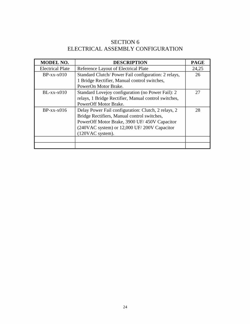
SECTION 6ELECTRICAL ASSEMBLY CONFIGURATION
MODEL NO. DESCRIPTION PAGEElectrical Plate Reference Layout of Electrical Plate 24,25
BP-xx-x010 Standard Clutch/ Power Fail configuration: 2 relays, 1 Bridge Rectifier, Manual control switches, PowerOn Motor Brake.
26
BL-xx-x010 Standard Lovejoy configuration (no Power Fail): 2 relays, 1 Bridge Rectifier, Manual control switches, PowerOff Motor Brake.
27
BP-xx-x016 Delay Power Fail configuration: Clutch, 2 relays, 2 Bridge Rectifiers, Manual control switches, PowerOff Motor Brake, 3900 UF/ 450V Capacitor (240VAC system) or 12,000 UF/ 200V Capacitor (120VAC system).
28
24

ELECTRIC PLATE ASSEMBLY
1
2
3
4
5
6
7
8
9
10
11
25

ELECTRICAL PLATE ASSEMBLYDiagram #’s refer to diagram on facing page.
Diagram#
AVS Part # Part Description
1 Electrical Plate2 Cam Bracket
MS-632-.375P Machine Screw: 6/32x0.375 PHMSP (2 per bracket)NT-632 Hex Nut 6/32 (2 per bracket)
3 EP-SW-10G4 Limit Switch, Simulated Roller (3 per plate)MS-440-1PHP Machine Screw 4/40x1 PHMSP (2 per switch)EP-SP-0325 Spacer 1/8” (2 per switch)NT-440 Hex Nut 4/40 (4 per switch)EP-AA-2202 Wire Terminal Pink Insulated Quick (2 per switch)
4 BS-BR-1212 Bridge Rectifier, 600 V 25 ampMS-632-.75PH Machine Screw: 6/32x0.75 PHMSPNT-632 Hex Nut 6/32
5 Toggle Switch Mounting BracketMS-632-.375P Machine Screw: 6/32x0.375 PHMSP (2 per bracket)NT-632 Hex Nut 6/32 (2 per bracket)EP-SS-3160 Wire Terminal #6 Spade
6 EP-SW-1200 Toggle Switch SPDT Center OffEP-BB-2206 Wire Terminal Blue Insulated Quick (3 per switch)
7 EP-SW-3200 Toggle Switch TPDT Center OffEP-BB-2206 Wire Terminal Blue Insulated Quick (9 per switch)
8 EP-TR-2131 12x Terminal Block-18 gageMS-632-.75PH Machine Screw: 6/32x0.75 PHMSP (2 per block)NT-632 Hex Nut 6/32 (2 per block)
9 EP-RB-2002 Relay Base, Surface Mount, 2 Pole (2 per plate)MS-632-.75PH Machine Screw: 6/32x0.75 PHMSP (2 per base)NT-632 Hex Nut 6/32 (2 per base)
10 EP-OR-0120, orEP-OR-0240, orEP-OR-0024
Relay, DPDT, 120 VAC, orRelay, DPDT, 240 VAC, orRelay, DPDT, 24 VAC
EP-OR-CLIP Relay Hold Down Clip11 EP-FR-2102, or
EP-FR-2103, orEP-FR-2104, orEP-FR-2007, orEP-FR-2010
20 MFD Capacitor, for 115 VAC/ 23 RPM Motor, or30 MFD Capacitor, for 115 VAC/ 40 RPM Motor, or40 MFD Capacitor, for 115 VAC/107 RPM Motor, or 7 MFD Capacitor, for 230 VAC/ 40 RPM Motor, or10 MFD Capacitor, for 230 VAC/107 RPM Motor
EP-WT-014W Wire Tie, 14 inch116-WIRE Wire, 16 AWG stranded for assembly
26

| | | | | | | | | | | |LINE NTL GRN |CLO OPN NTL | MOTOR |BLK RED WHT GRN SUPPLY | CONTROL | BRAKE | MOTOR120 V or 220 V| LINE | | CONNECTIONS
CO
MN
O
NC
CO
MN
O
NC
CO
MN
O
NC
BP-xx-x010
MOV
Red
White
Black
Black
Yellow
WhiteBlack
Bla
ck
White
White
White
Black
BlackRed
White
White
Red
Black
Black
Red to CLUTCH
White
Green
Red
Bla
ckO
rang
e
Bla
ck
Whi
te
Bla
ck
Red
Whi
te
Ora
nge
Yel
low
Red
Whi
te
Bla
ck
Bla
ck
Red
RedY
ello
w
Red
Yellow
Whi
teModel AO: 115 VAC/ 40 rpm Motor 90 VDC Clutch & PowerOn Brake R=8.2 K ohm 150 MOV 115 VAC LY2 Omron Relays
Model DR: 230 VAC/ 40 rpm Motor 190 VDC Clutch & PowerOn Brake R=16 K ohm 250 MOV 230 VAC LY2 Omron Relays
update 10/1/02
Bla
ck
Bla
ck
White
Bridge
Rectifier
R
R
Yel
low
Red
Bla
ck
Red
Red
Yel
low
Bla
ck
Bla
ck
Red
Fail-Safe
Open
Close
27

Model AO: 115 VAC/ 40 rpm Motor 90 VDC PowerOff Brake 2-8.2 K ohm 2 Watt Resistors 2-115 VAC LY2 Omron Relays
Model DR: 230 VAC/ 40 rpm Motor 190 VDC PowerOff Brake 2-16 K ohm 2 Watt Resistors 2-230 VAC LY2 Omron Relays
| | | | | | | | | | | |LINE NTL GRN |CLO OPN NTL | MOTOR |BLK RED WHT GRN SUPPLY | CONTROL | BRAKE | MOTOR120 V or 220 V| LINE | | CONNECTIONS
CO
MN
O
NC
CO
MN
O
NC
CO
MN
O
NC
BL-xx-x010
Red
White
BlackBlack
White
Black
Bla
ck
White
White
White
BlackRed
White
White
Red
Black
White
Green
Red
Ora
nge
Bla
ck
Whi
te
Bla
ck
Red
Whi
te
Ora
nge
Yel
low
Red
Whi
te
Bla
ck
Bla
ck
Red
Red
Yel
low
Yellow
Whi
teupdate 10/1/02
Bla
ck
White
Bridge
Rectifier
R
RYel
low
Yellow
Bla
ck
Black
Bla
ck
Bla
ck
Red
Red
Bla
ck
Whi
te
28
| | | | | | | | | | | |LINE NTL GRN CLO OPN NTL MOTOR BLK RED WHT GRN SUPPLY CONTROL BRAKE MOTOR120 V or 220 V LINE CONNECTIONS
CO
MN
O
NC
CO
MN
O
NC
CO
MN
O
NC
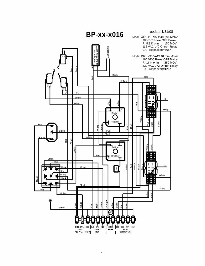
BP-xx-x016
Red
White
Bla
ck
Black
White
Black
Bla
ckWhite
White
White
BlackRed
White
White
Red
White
Green
Red
Ora
nge
Bla
ck
Whi
te
Bla
ck
Red
Whi
te
Ora
nge
Yel
low
Red
Whi
te
Bla
ck
Bla
ck
Red
Red
Yel
low
Yellow
Whi
te
Model AO: 115 VAC/ 40 rpm Motor 90 VDC PowerOFF Brake R=8.2 K ohm 150 MOV 115 VAC LY2 Omron Relay CAP (capacitor)=565K
Model DR: 230 VAC/ 40 rpm Motor 190 VDC PowerOFF Brake R=16 K ohm 250 MOV 230 VAC LY2 Omron Relay CAP (capacitor)=125K
update 1/31/08
Bla
ck
White
Bridge
Rectifier
R
Yel
low
Yel
low
Bla
ck
Black
Bla
ck
Red
Red
Bridge
Rectifier
MOV
CA
P
Blu
e C
apac
itor
1200
0 M
FD
360
V
to C
LUT
CH
Red
Black
Bla
ck
Red
Red
Black
+
-
-
+
Black
Bla
ck
Whi
te
Yel
low
Yel
low
Bla
ck
Yel
low
Whi
te
Whi
te
Bla
ck
Red
White
Black
Red
+
R
Bla
ck
29

TROUBLESHOOTING GUIDE
Symptom Cause Remedy SeePage
1.
Unit will not run Fail safe switch activated
Turn off power & turn screw shaft by hand to get off fail safe switch
3
11
No Power to unit Check input voltage, breaker 26-28
No control signal Check manual operation at unit& control
2.
Motor hums but won’t run
Motor brake not releasing
Check voltage to brake:90vdc for 120V unit200vdc for 240V unitNo voltage, bad rectifierBrake coil may be
shorted
24-28
Both relays activated (trying to run both directions
Activate open or close limit switch to see if motor will run (relay sticking, or control sending both signals)
3
24-28
3.
Clutch slips (Power Fail models) – Ballscrew shaft will not turn with motor
Gap too large With power off, check gap between electromagnet & disc – adjust as necessary
The electromagnet must be adjusted toward (or away from)the disc. There are 2 allen/set screws holding electromagnet in place.
18
Dirt or grease on clutch
Clean clutch surfaces using a rapid evaporating solvent
Curtain load too great
Check for binding cables, pulleys, etc.
7-10
No or low voltage to clutch
Check voltage to electromagnet:
90vdc for 120V unit200vdc for 240V unitNo voltage, bad rectifierClutch coil may be
shorted
26,28
4.
Unit runs only one direction
Sticking relay Interchange relays; replace faulty relay
24-28
Sticking or faulty limit switch
Lever arm of limit switch may need to be adjusted (always onno matter position on cam); replace limit switch
3
30

5,
Clutch growls Electromagnet & disc are out of alignment
With power off, loosen bolts forthrust bearing (#5), and adjust bearing to center disc to electromagnet
18
6.
Curtains will not drop (Power Fail models)
No clutch gap With power off, check that ballscrew shaft is free to turn. Check gap (see item 3 above)
18
Centrifugal brake sticking
Check that arms and shoes of centrifugal brake move freely
18
7.
Ballnut fails, loses bearings
Ballscrew shaft notgreased
Replace ballnut, and check for wear and galling on ballscrew shaft
Curtain, or cable load not balanced
7-10
8.
Motor not running, but hot
Thermal overload switch tripped
Motor ran excessively: check control settings to see if they are too tight.
Brake failure causes unit to drift off close limit switch and run repeatedly.
Brake not releasing (see item 2above)
Relay sticking, runs past close limit, hits failsafe switch, drifts backwards and runs repeatedly.
9.
Unit repeatedly runs to and drifts off close limit switch
Brake failure
(Power On)
Bridge rectifier not supplying required voltage (see item 2)
Brake electromagnet failed (coil bad)
21
(Power Off) Fiber disc in brake electromagnet damaged
22
31

LIMITED WARRANTY
If it appears within one year from the date of invoice between the Purchaser and Agri Ventilation Systems, LLC, that any products or component parts do not conform to the specifications and physical descriptions given to the Purchaser, orthat such products or component parts do not perform the function for which theywere intended, the Purchaser, at their expense, shall return the products or component parts to the Seller, as prescribed in the AVS Return Materials Policy, with a RGA number, and a written report of defects or failed performance. The Seller shall review the report and inspect the items, and shall determine warrantystatus, and shall authorize, where applicable, either the repair or replacement of any non-conforming, or non-functioning product or component parts. The liabilityof the Seller to the Purchaser arising out of the supply of, or use of the product orcomponent parts, whether such liability shall arise during the warranty period, shall in no case exceed the amount paid by the Seller in the repair or replacement of non-conforming, or non-functioning product or component parts. Upon the expiration of the warranty period, all liability of the Seller shall terminate.
Any warranty will be terminated if any product or component parts are installed improperly, misused, misapplied, tampered with, abused, modified, or altered without authorization from Agri Ventilation Systems, LLC. Warranty will not applyto defects of failures caused by, or due to Acts of God, or nature.
WARNING: WHEN THE PRODUCT OR COMPONENT PARTS ARE USED INA LIFE SUPPORT VENTILATION SYSTEM, WHERE FAILURE COULD RESULT IN LOSS OR INJURY, THE USER SHALL PROVIDE ADEQUATE PERSONAL ATTENTION, BACK-UP VENTILATION, SUPPLEMENTARY NATURAL VENTILATION, OR FAILURE SYSTEMS, ETC., NECESSARY TO CONTROL THE OPERATION, OR ACKNOWLEDGE WILLINGNESS TO ACCEPT THE ASSOCIATED RISKS OF SUCH LOSS OR INJURY.
This equipment is offered for sale specifically on the Purchaser’s acceptance of the above condition and the manufacturer’s warranty for this equipment. Acceptance, retention, installation, or operation of this equipment by the Purchaser shall be considered as acknowledgment and acceptance of the aboveconditions.
AGRI VENTILATION SYSTEMS, LLCP. O. Box 40, Dayton, VA 22821
32