ball sensor fusion and ball interception behaviours for a...
TRANSCRIPT
Ball sensor fusion and ball interception behaviours for aRobotic Soccer Team
Joao Silva, Nuno Lau, Joao Rodrigues and Jose Luıs Azevedo
IEETA / Department of Electronics, Telecommunications andInformaticsUniversity of Aveiro, Portugal
{a25385,nunolau,jmr,jla}@ua.pt
Abstract. This paper presents some of the work developed in the CAMBADAteam at the sensor and information fusion level, as well as developments at thebehaviours level. Specifically, the ball sensor and information fusion techniques,to improve the position and velocity reliability, are described, as well as intercep-tion behaviours based on that reliable velocities, allowing for different approach-ing behaviours to the ball, are depicted. The described workimproved the teamperformance, allowing it to distinctively achieve the 1st place in the Portugueserobotics open Robotica2008 and in the world championship RoboCup2008.
1 Introduction
Robotic soccer is nowadays a popular research domain in the area of multi robot sys-tems. RoboCup1 is an international joint project to promote artificial intelligence, roboticsand related fields that includes several leagues, each one with a different approach, someonly at software level, others at hardware, with single or multiple agents, cooperativeor competitive [1]. The CAMBADA team was created to participate in the middle sizeleague of robotic soccer, which requires the integration ofseveral technologies in or-der for the robots to play soccer, such as autonomous agents architectures, multi-agentcooperation, strategy acquisition, real-time reasoning,control and sensor fusion.
In the context of RoboCup, the “middle size league” (MSL) is one of the mostchallenging. In this league, each team is composed of 4 to 6 robots with maximum sizeof 50x50cm base, 80cm height and a maximum weight of 40Kg, playing in a field of18x12m. The rules [2] of the game are similar to the official FIFA rules, with requiredchanges to adapt for the playing robots. Each robot is autonomous and has its ownsensorial means. They can communicate among them through a wireless network andwith an external computer acting as a coach. This coach computer has no sensor of anykind, it only knows what is reported by the playing robots. The agents should be ableto evaluate the state of the world and make decisions suitable to fulfil the cooperativeteam objective.
CAMBADA, Cooperative Autonomous Mobile roBots with Advanced DistributedArchitecture, is the Middle Size League Robotic Soccer team from Aveiro University.
1 http://www.robocup.org/

The project started in 2003, coordinated by the IEETA2 ATRI3 group. It involves peopleworking on several areas for building the mechanical structure of the robot, its hardwarearchitecture and controllers and the software developmentin areas such as image anal-ysis and processing, sensor and information fusion, reasoning and control.Since its creation, the team has participated in several competitions, both national andinternational. Each year, new challenges are presented, and new objectives are defined,always with a better team performance in sight. The team achieved the 1st place inthe national competitions Robotica2007 and Robotica2008, the 5th place in the worldchampionship RoboCup2007 and the 1st place in the world championship RoboCup2008.
This paper includes a brief description of the CAMBADA software agent in Sec-tion 2 to contextualize the described work. Having the objective of developing newbehaviours to intercept the ball based on a prediction of itsfuture position rather thanmoving to its current position, one felt the necessity to first improve the reliability of theestimation of the ball position and velocity. For that, improvements on the integration ofball information and sensor fusion of ball data were necessary, which are described inSection 3. The developed behaviours are presented in Section 4 and some conclusionsand comments on the developed work are presented in Section 5.
2 CAMBADA
The CAMBADA team is currently composed of 6 robots (Fig. 1.a)with a general ar-chitecture described in [3,4,5] and also a description of the physical structure is presentin [6].
The software system in each robot is distributed among various computational units.High level functions are executed on a PC, while low level functions are executed on mi-crocontrollers. A cooperative sensing approach based on a Real-Time Database (RTDB)[3,7,8] has been adopted. The RTDB is a data structure used bythe robots to share theirworld models. It is updated and replicated in all players in real-time. The high-levelprocessing loop starts by integrating perception information gathered locally by therobot, namely, information coming from the vision system and odometry informationcoming from the low-level layer. This information is afterwards stored in the RTDB.The next step is to integrate the robot local information with the information sharedby team-mates, disseminated through the RTDB. The data stored in the RTDB is thenused by another set of processes that define the specific robotbehaviour, by generatingcommands that are sent down to the lowlevel control layer [6].
The tasks performed by the high-level loop are described in Fig. 1.b. As shownin the diagram, the integrator module is responsible for getting the sensorial data andbuilding the representation of the state of the world. This representation is then usedby the behaviours to define their set points and by the higher level layer. The roles anddecision modules use the behaviours and act according to theconditions of the state ofthe world. The behaviours are the ones responsible for defining the commands to besent down to the actuators of the robot.
2 Instituto de Engenharia Electronica e Telematica de Aveiro - Aveiro’s Institute of Electronicand Telematic Engineering
3 Actividade Transversal em Robotica Inteligente - Transverse Activity on Intelligent Robotics

a) b)
Fig. 1. Left, a): Picture of the team robots; Right,b): High-level tasks diagram.
The work described was done at the three lower levels of the diagram, the integrator,the worldstate and the behaviours.
3 Integration
The integrator module is responsible for updating the worldstate representation. Forthat task it may use the values stored in the previous representation, the current sensormeasures (eventually after pre-processing) that has just arrived, the current actuatorcommands and also information that is available from other robots sensors or worldstate. This is essentially an information fusion problem. The most common methods totackle information fusion are based on probabilistic approaches, including Bayes rule,Kalman filter and Monte Carlo methods [9]. Within RoboCup several teams have usedKalman filters for the ball position estimation [10,11,12,13]. In [13] and [12] severalinformation fusion methods are compared for the integration of the ball position usingseveral observers. In [13] the authors conclude that the Kalman reset filter shows thebest performance.
In our case, a Kalman filter was chosen to refine the estimationof the ball position.The integrator module is the first task to be executed by the software agent, and startsby getting the RTDB vision information. It then updates the information provided bythe low-level micro controllers. This update includes getting the odometry values andcalculating the displacements since last cycle for x, y and angular components andgetting the current battery and ball engaged sensor status.A verification of the coachcomputer is made, by reading the coach information on the RTDB. The coach computerdefines the team colour and the goal colour. Also, the start and stop commands are givenby the coach computer. The team mates information is read from the RTDB and theobstacle vector in the worldstate is updated by the current vision obstacle information.

The localisation algorithm (based on the Tribots team algorithm [14])then uses thevision information of the field lines and the odometry displacements to estimate theagent position on the field. After getting the position, a linear regression is used toestimate the agent velocity. Since the line based localisation can be ambiguous due tosymmetry of the field, a verification is needed. This verification is made by gettingthe robot orientation from an electronic compass and estimate the orientation error.Afterwards, the integration of the ball position and velocity is done, the state of thegame is updated and a free path for the opponent goal is estimated.
All the information available from the sensors in the current cycle is kept in specificdata structures (Fig. 2), for posterior fusion and integration, based on both the currentinformation and the previous state of the world.
Fig. 2. Integrator functionality diagram.
3.1 Ball position estimation
The information of the ball state (position and velocity) is, perhaps, the most important,as it is the main object of the game and is the base over which most decisions are taken.Thus, its integration has to be as reliable as possible. To accomplish this, a Kalmanfilter implementation was created to filter the ball positionestimates given by the visualinformation.
It is assumed that the ball velocity is constant between cycles. Although that is nottrue, due to the short time variations between cycles, around 40 milliseconds, and giventhe noisy environment and measurement errors, it is a ratheracceptable model for theball movement. Thus, no friction is considered to affect theball, and the model doesn’tinclude any kind of control over the ball. Therefore, given the Kalman filter formulation(described in [15]), the assumed state transition model is given by
Xk =
[
1 ∆T
0 1
]
Xk−1
whereXk is the state vector containing the position and velocity of the ball. Technically,there are two vectors of this kind, one for each cartesian dimension (x,y). This velocityis only internally estimated by the filter, as the robot sensors can only take measure-ments on the ball position. After defining the state transition model based on the ball

movement assumptions described above and the observation model, the description ofthe measurements and process noises are important issues toattend.
The measurements noise can be statistically estimated by taking measurements of astatic ball position at known distances. The standard deviation of those measurementsis used to calculate the variance and thus define the measurements noise parameter.In practice, the measurements of the static ball were taken while the robot was rotatingover itself, to simulate movement and the trepidation it causes, so that the measurementswere as close to real game conditions as possible. Some of theresults are illustrated inFig. 3.
0 1 2 3 4 5 6−0.5
0
0.5
YY field coordinate (m)
XX
fiel
d co
ordi
nate
(m
) Robot 2 noisy ball position at several distances
ball at 1 meter
ball at 2 meters
ball at 3 meters
ball at 4 meters
0 1 2 3 4 5 6−0.5
0
0.5
YY field coordinate (m)
XX
fiel
d co
ordi
nate
(m
) Robot 4 noisy ball position at several distances
ball at 1 meter
ball at 2 meters
ball at 3 meters
ball at 4 meters
Fig. 3. Noisy position of a static ball taken from rotating robots.
A relation between the distance of the ball to the robot and the measurements stan-dard deviation is modeled by the 2nd degree polynomial best fitting the data set in aleast-squares sense (Fig. 4). A 1st degree polynomial does not fit the data properly, andassumes negative values for positive distance, which is notacceptable. Given the fewknown points, a 3rd degree polynomial would perfectly fit all4 of them. However, theseknown points are also estimated and thus cannot be taken as exact. For that reason, acurve that would exactly fit them is not desirable.
As for the process noise, this is not trivial to estimate, since there is no way totake independent measurements of the process to estimate its standard deviation. Theprocess noise is represented by a matrix containing the covariances correspondent tothe state variable vector.
Empirically, one could verify that forcing a near null process noise causes the filterto practically ignore the read measures, leading the filter to emphasise the model pre-diction. This makes it too smooth and therefore inappropriate. On the other hand, if itis too high, the read measures are taken into too much accountand the filter returns themeasures themselves.
To face this situation, one had to find a compromise between stability and reaction.Given the nature of the two components of the filter state, position and speed, one mayconsider that their errors do not correlate.

Fig. 4. Representation of the standard deviation value for variable distance to the robot. Data setpoints as blue dots. 1st degree polynomial as dashed line, 2nd degree polynomial as solid line.
Because we assume a uniform movement model that we know is notthe true natureof the system, we know that the speed calculation of the modelis not very accurate. Aprocess noise covariance matrix was empirically estimated, based on several tests, sothat a good smoothness/reactivity relationship was kept (Fig. 5).
Fig. 5. Kalman filter over theoretical noisy positions of the ball. The unfiltered ball positions arethe blue hexagrams, filtered positions are the red dots.
In practice, this approach proved to improve the estimationof the ball position. Fig-ure 6 represents a capture of a ball movement, where the blackdots are the ball positionsestimated by the robot visual sensors and thus are unfiltered. Red stars represent the po-sition estimations after applying the Kalman filter. The ball was thrown against the robotand deviated accordingly and the robot position is represented by the black star in itscentre and its respective radius. It is easily perceptible that the unfiltered positions areaffected by much noise and the path of the ball after the collision is deviated from thereal path. The filtered positions however, seem to give a muchbetter approximation tothe real path taken by the ball.

Fig. 6. Plot of a ball movement situation. See text for details.
Using the filtera-priori estimation, a system to detect great differences betweenthe expected and read positions was possible to implement, allowing to detect harddeviations on the ball path.
3.2 Velocity estimation
The calculation of the ball velocity is a feature becoming more and more important overthe time. It allows that better decisions can be implementedbased on the ball speedvalue and direction. Assuming the same ball movement model described in the previ-ous section, constant ball velocity between cycles and no friction considered, one couldtheoretically calculate the ball velocity by simple instantaneous velocity of the ball withthe first order derivative of each component∆D
∆T, being∆D the displacement on con-
secutive measures and∆T the time interval between consecutive measures. However,given the noisy environment it is also predictable that thisapproach would be greatlyaffected by that noise and thus its results would not be satisfactory (as it is easily visiblein Fig. 7.a).
To keep a calculation of the object velocity consistent withits displacement, an im-plementation of a linear regression algorithm was chosen. This approach based on linearregression ([16]) is similar to the Tribots team [17] velocity estimation. By keeping abuffer of the lastm measures of the object position and sampling instant (in this casebuffers of 9 samples were used), one can calculate a regression line to fit the positions ofthe object. Since the object position is composed by two coordinates(x,y), we actuallyhave two linear regression calculations, one for each dimension, although it is made ina transparent way, so the description in this section is presented generally, as if only onedimension was considered.
When applied over the positions estimated by the Kalman filter, the linear regressionvelocity estimations are much more accurate than the instant velocities calculated by∆D
∆T, as visible in Fig. 7.b.

a) b)
Fig. 7. Velocity representation using: Left,a): consecutive measures displacement; Right,b):linear regression over Kalman filtered positions.
In order to try to make the regression converge more quickly on deviations of theball path, a reset feature was implemented, which allows deletion of the older values,keeping only then most recent ones. This reset results from the interaction with theKalman filter described above, which triggers the velocity reset when it detects a harddeviation on the ball path.
Although in this case the Kalman filter internal functioningestimates a velocity,the obtained values were tested to confirm if the linear regression of the ball positionswas still needed. Tests showed that the velocity estimated by the Kalman filter hasa slower response than the linear regression estimation when deviations occur. Giventhis, the linear regression was used to estimate the velocity because quickness of con-vergence was preferred over the slightly smoother approximation of the Kalman filterin the steady state. That is because in the game environment,the ball is very dynamic,it constantly changes its direction and thus a convergence in less than half the cycles ismuch preferred.
The results achieved by the presented work served as a base for the development ofthe new behaviours presented in the next section.
4 Behaviours
The behaviours define the velocity to apply on the wheels, through 3 attributesvelX,velY and velA, for velocity’s x, y and angular components, respectively. Given thespecificity of each different behaviour, they inherit the responsability of calculatingthe values of the velocity by its own means. Also, the controlof both the kicker and thegrabber is kept by the behaviours.
For the presented behaviours, the velocities are calculated based on the need to getto the defined target position.
The need for a way to approach the ball other than moving directly towards itsinstantaneous position became evident since it was verifiedthat the robot describes a

completely unnecessary arc to get to the ball and in most cases would have to chase itback, loosing much time and strategic advantage.
Avoiding this kind of situations was a need, and thus the interception algorithmsdescribed below were created.
4.1 Passive interception
One approach to intercept the ball is to passively “wait” forit. This approach can beadvantageous in situations where the robot should not go forthe ball, but rather interceptits path and then, if the ball reaches it, move forward with it. The used approach is basedon the ball velocity direction. The ball speed vector is extended as a line segment withorigin in the ball. That line represents the ball path and theclosest point of the pathline to the robot position is calculated; geometrically, the perpendicular point is alwaysthe nearest. The calculated point is the one where the robot should go to in order tointercept the ball path (Fig. 8).
Fig. 8. Illustration of the passive interception behaviour. The ball velocity vectorV is extendedas a line defining its path. The robot calculates the closest point over the line, relatively to itself,and defines it as the interception point.
In the practical experiment represented in Fig. 9, the ball moves from right to left ina practically straight line. The ball positions are represented by blue hexagrams and therobot positions by red dots. The calculated interception point is represented by a smallblack circle, in this case, near (0.2, -1.7). It is visually verifiable that the interceptionpoint is, as expected, the perpendicular interception of the ball velocity direction lineand the robot velocity direction line.
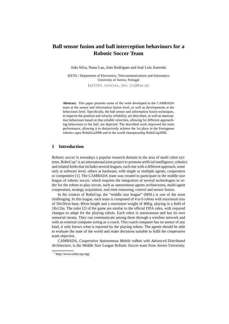
The results obtained by this approach were effective, although this behaviour doesnot guarantee the robot gets to the interception point before the ball in minimum time,as it only evaluates its direction and goes to the path. For that, another behaviour wasdefined, the active interception.
4.2 Active interception
The active interception appears naturally from the passiveone, as in certain situationsone is interested in getting in front of the ball in minimum time, and necessarily hasto evaluate, besides the velocity direction, the speed value to calculate an interceptionpoint where the robot can get to before the ball. The algorithm used to calculate the in-terception point assumes a constant robot speed. Considering that unknown coefficients
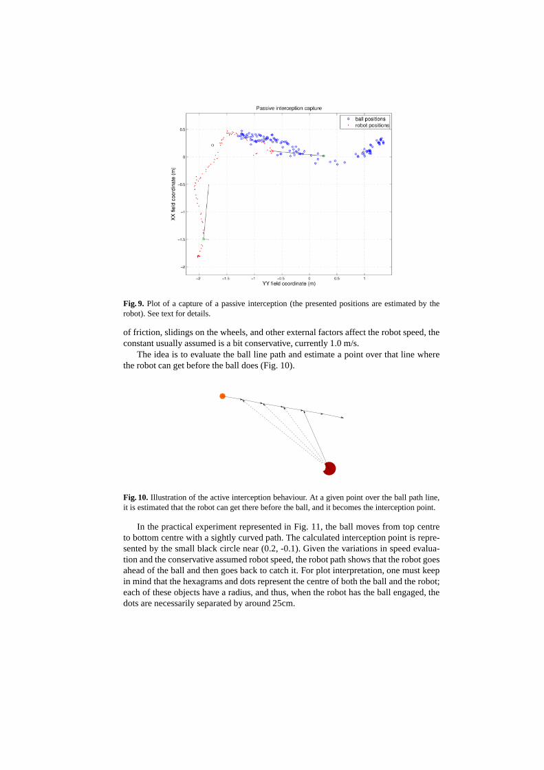
Fig. 9. Plot of a capture of a passive interception (the presented positions are estimated by therobot). See text for details.
of friction, slidings on the wheels, and other external factors affect the robot speed, theconstant usually assumed is a bit conservative, currently 1.0 m/s.
The idea is to evaluate the ball line path and estimate a pointover that line wherethe robot can get before the ball does (Fig. 10).
Fig. 10. Illustration of the active interception behaviour. At a given point over the ball path line,it is estimated that the robot can get there before the ball, and it becomes the interception point.
In the practical experiment represented in Fig. 11, the ballmoves from top centreto bottom centre with a sightly curved path. The calculated interception point is repre-sented by the small black circle near (0.2, -0.1). Given the variations in speed evalua-tion and the conservative assumed robot speed, the robot path shows that the robot goesahead of the ball and then goes back to catch it. For plot interpretation, one must keepin mind that the hexagrams and dots represent the centre of both the ball and the robot;each of these objects have a radius, and thus, when the robot has the ball engaged, thedots are necessarily separated by around 25cm.

Fig. 11. Plot of a capture of an active interception (the presented positions are estimated by therobot). See text for details.
This interception behaviour takes advantage of a well refined ball velocity estima-tion, and proved to be quite effective.
5 Conclusion
Reliable estimations of the ball position and velocity are an important aspect to develop,since high level decisions can and should be based on the way the ball is moving.
The chosen techniques for information and sensor fusion proved to be effectivein accomplishing their objectives. The Kalman filter allowsto filter the noise on theball position and provides an important prediction featurewhich allows fast detectionof deviations of the ball path. The linear regression used toestimate the velocity isalso effective, and combined with the deviation detection based on the Kalman filterprediction error, provides a faster way to recalculate the velocity in the new trajectory.
At the behaviours level, the implementation of the interceptions and the approachpoint calculation are the first step for “predictive” features on the CAMBADA robots,as they allow for movement ahead of the ball, instead of goingdirectly to it. However,it was only possible to make them effective due to the improvement of the ball velocityaccuracy.
The new passive interception behaviour brought a new dynamic to the game, as itwas used in real game situations during the Robotica2008 games and RoboCup2008games.
The active interception behaviour was not tested in real game situations yet, but canprovide a good solution for future needs of the team strategy.
The described work improved the team performance, allowingit to distinctivelyachieve the 1st place in the Portuguese robotics open Robotica2008 and the 1st place inthe RoboCup2008.
Acknowledgments
This work was partially supported by project ACORD AdaptiveCoordination of RoboticTeams, FCT/PTDC/EIA/70695/2006.
References
1. Kitano, H., Asada, M., Kuniyoshi, Y., Noda, I., Osawa, E.:RoboCup: The Robot World CupInitiative. Proceedings of the first international conference on Autonomous agents (1997)340–347
2. MSL Technical Committee 1997-2008: Middle Size Robot League Rules and Regulationsfor 2008 (2007)
3. Almeida, L., Santos, F., Facchinetti, T., Pedreiras, P.,Silva, V., Lopes, L.: Coordinatingdistributed autonomous agents with a real-time database: The CAMBADA project. In: Proc.of the ISCIS, Springer (2004)
4. Silva, V., Marau, R., Almeida, L., Ferreira, J., Calha, M., Pedreiras, P., Fonseca, J.: Im-plementing a distributed sensing and actuation system: TheCAMBADA robots case study.In: Proc. of the 10th IEEE Conference on Emerging Technologies and Factory Automation,ETFA 2005. Volume 2. (2005)
5. Azevedo, J., Cunha, B., Almeida, L.: Hierarchical distributed architectures for autonomousmobile robots: A case study. In: Proc. of the 12th IEEE Conference on Emerging Technolo-gies and Factory Automation, ETFA 2007. (2007) 973–980
6. Azevedo, J.L., Lau, N., Corrente, G., Neves, A., Cunha, M.B., Santos, F., Pereira, A.,Almeida, L., Lopes, L.S., Pedreiras, P., Vieira, J., Martins, D., Figueiredo, N., Silva, J., Fil-ipe, N., Pinheiro, I.: CAMBADA’2008: Team Description Paper (2008)
7. Santos, F., Almeida, L., Pedreiras, P., Lopes, L., Facchinetti, T.: An Adaptive TDMA Pro-tocol for Soft Real-Time Wireless Communication among Mobile Autonomous Agents. In:Proc. of the Int. Workshop on Architecture for Cooperative Embedded Real-Time Systems,WACERTS 2004. (2004)
8. Pedreiras, P., Teixeira, F., Ferreira, N., Almeida, L., Pinho, A., Santos, F.: Enhancing theReactivity of the Vision Subsystem in Autonomous Mobile Robots Using Real-Time Tech-niques. In: RoboCup Symposium: Papers and Team DescriptionPapers, Springer (2005)
9. Durrant-Whyte, H., Henderson, T.: Multisensor Data Fusion. In: Springer Handbook ofRobotics. Springer (2008)
10. Lauer, M., Lange, S., Riedmiller, M.: Modeling Moving Objects in a Dynamically ChangingRobot Application. In: Advances in Artificial Intelligence. Springer (2005) 291–303
11. XU, Y., JIANG, C., TAN, Y.: SEU-3D 2006 Soccer SimulationTeam Description (2006)12. Marcelino, P., Nunes, P., Lima, P., Ribeiro, M.I.: Improving object localization through
sensor fusion applied to soccer robots. In: Proc. of the Rob´otica2003. (2003)13. Ferrein, A., Hermanns, L., Lakemeyer, G.: Comparing Sensor Fusion Techniques for Ball
Position Estimation. In: Proc. of the RoboCup 2005 Symposium. Springer (2005)14. Lauer, M., Lange, S., Riedmiller, M.: Calculating the perfect match: an efficient and accurate
approach for robot self-localization. In: RoboCup Symposium, Springer (2005)15. Bishop, G., Welch, G.: An Introduction to the Kalman Filter. In: Proc of SIGGRAPH,
Course 8. Number NC 27599-3175, Chapel Hill, NC, USA (2001)16. Motulsky, H., Christopoulos, A.: Fitting models to biological data using linear and nonlinear
regression. GraphPad Software Inc. (2003)17. Lauer, M., Lange, S., Riedmiller, M. In: Modeling MovingObjects in a Dynamically Chang-
ing Robot Application. Springer (2005) 291–303