ball state university spill prevention, control, and...
TRANSCRIPT
Ball State University Spill Prevention, Control, and Countermeasure (SPCC) Plan
SPILL PREVENTION, CONTROL,AND COUNTERMEASURE
(SPCC) PLAN
2000 West University AvenueMuncie, Delaware County, Indiana 47306
July 2011 version
Prepared by the:
Environmental Health and Safety OfficeBSU Facilities Planning and Management
3401 North Tillotson Avenue (SV 203)Muncie, Indiana 47306
Ball State University Spill Prevention, Control, and Countermeasure (SPCC) Plan
-ii-
TABLE OF CONTENTS
Page
List of Acronyms and Abbreviations iv
INTRODUCTION 1
Part 1: Plan Administration
1.1 Management Approval and Designated Person 3
1.2 Professional Engineer Certification 3
1.3 Location of SPCC Plan 4
1.4 Plan Review 4
1.5 Facilities, Procedures, Methods, or Equipment Not Yet Fully Operational 5
1.6 Cross-Reference with SPCC Provisions 5
Part 2: General Facility Information
2.1 Facility Description 8
2.2 Evaluation of Discharge Potential 19
Part 3: Discharge Prevention – General SPCC Provisions
3.1 Compliance with Applicable Requirements 22
3.2 Facility Layout Diagram 24
3.3 Spill Reporting 24
3.4 Potential Discharge Volumes and Direction of Flow 24
3.5 Containment and Diversionary Structures 35
3.6 Practicability of Secondary Containment 36
3.7 Inspections, Tests, and Records 37
3.8 Personnel, Training, and Discharge Prevention Procedures 40
3.9 Security 41
3.10 Oil Transfer Procedures 41
3.11 Brittle Fracture Evaluation 44
3.12 Conformance with State and Local Applicable Requirements 44
Part 4: Discharge Prevention – SPCC Provisions for Onshore Facilities(Excluding Production Facilities)
4.1 Facility Drainage 45
4.2 Bulk Storage Containers 45
Ball State University Spill Prevention, Control, and Countermeasure (SPCC) Plan
-iii-
4.3 Transfer Operations, Pumping, and In-Plant Processes 49
Part 5: Discharge Response
5.1 Response to a Minor Discharge 50
5.2 Response to a Major Discharge 51
5.3 Waste Disposal 53
5.4 Discharge Notification 53
5.5 Cleanup Contractors and Equipment Suppliers 43
Tables
Table 1-1: Plan Review Log 6
Table 1-2: SPCC Cross-Reference 7
Table 2-1: Summary Table of Bulk Oil Tanks, Containers, and Oil-Filled Equipment 12
Table 2-2: Oil-Filled Electric Transformers 14
Table 2-3: Emergency Generators with Oil Tankage 17
Table 2-4: Hydraulic Elevators 18
Table 2-5: Reportable Oil Discharge History 21
Table 3-1: Potential Discharge Volume and Direction of Flow 24
Table 3-2: Inspection and Testing Program 38
Table 3-3: Fuel Transfer Procedures 43
Appendices Rear
A: Site Location and Facility Diagram of
B: Substantial Harm Determination Plan
C: Facility Inspection Checklists
D: Record of Containment Dike Drainage
E: Record of Discharge Prevention Briefings and Training
F: Calculation of Secondary Containment Capacity
G: Records of Tank Integrity and Pressure Tests
H: Emergency Contacts
I: Discharge Notification Form
J: Discharge Response Equipment Inventory
K: Agency Notification Standard Report (Reportable Spills / SPCC Submittal)
Ball State University Spill Prevention, Control, and Countermeasure (SPCC) Plan
-iv-
LIST OF ACRONYMS AND ABBREVIATIONS
API American Petroleum Institute
AST Aboveground Storage Tank
BSU Ball State University (or University)
CSA Container Storage Area
CRDM Continuous Release Detection Monitoring
DW Double Walled (with integral interstitial monitoring)
EHS BSU Environmental Health and Safety Office
EPA U.S. Environmental Protection Agency
FPM BSU Facilities Planning and Management
IDEM Indiana Department of Environmental Management
MBWQ City of Muncie Bureau of Water Quality
NPDES National Pollutant Discharge Elimination System
NRC National Response Center
OSHA Occupational Safety and Health Administration
PE Professional Engineer
POTW Publicly Owned Treatment Works
PPE Personal Protection Equipment
RPB Release Prevention Barrier
SPCC Spill Prevention, Control, and Countermeasure
STI Steel Tank Institute
SV BSU Service and Stores Building (includes Bus Garage)
UL Underwriters Laboratory
UST Underground Storage Tank
Ball State University Spill Prevention, Control, and Countermeasure (SPCC) Plan
-1-
INTRODUCTION
Purpose
The purpose of this Spill Prevention, Control, and Countermeasure (SPCC) Plan is to describemeasures implemented by Ball State University (University, or BSU) to ensure the safe handlingand storage of oil, to prevent oil discharges from occurring, and to prepare Ball State Universityto respond in a safe, effective, and timely manner to mitigate the impacts of any oil dischargethat may occur.
This Plan has been prepared to meet the requirements of Title 40, Code of Federal Regulations,Part 112 (40 CFR part 112), and supersedes and wholly replaces the former Plan developed tomeet the earlier SPCC provisions in effect since 1974. The organization, overall format, andmuch of the standard wording of the Plan, is adopted from a sample SPCC Plan originallycreated by the EPA in 2005 and made available on their website.
In addition to fulfilling requirements of 40 CFR Part 112, this SPCC Plan is used as a referencefor oil storage information and testing records, as a tool to communicate practices on preventingand responding to discharges with employees, as a guide to facility inspections, and as aresource during emergency response. Appendix A includes the BSU facility location anddrawings showing pertinent features of the campus.
Ball State University management has determined that this facility does not pose a risk ofsubstantial harm under 40 CFR part 112, as demonstrated and recorded in the SubstantialHarm Determination included in Appendix B of this Plan.
This Plan provides guidance on key actions that Ball State University should perform to complywith the SPCC rule:
Complete monthly and annual site inspections as outlined in the Inspection,Tests, and Records section of this Plan (Section 3.7) using the inspectionchecklists included in Appendix C.
Perform preventive maintenance of equipment, secondary containment systems,and discharge prevention systems described in this Plan as needed to keep themin proper operating conditions (Appendix D and G).
Conduct annual employee training as outlined in the Personnel, Training, andSpill Prevention Procedures section of this Plan (Section 3.8) and documentthem on the log included in Appendix E.
If either of the following occurs, submit the SPCC Plan to the EPA Region 5Regional Administrator (RA) and the Indiana Department of Environmental
Ball State University Spill Prevention, Control, and Countermeasure (SPCC) Plan
-2-
Management (IDEM), along with other information as detailed in Section 5.4 ofthis Plan and illustrated in Appendix K.
The facility discharges more than 1,000 gallons of oil into or upon thenavigable waters of the U.S. or adjoining shorelines in a single spill event;or,
The facility discharges oil in quantity greater than 42 gallons in each oftwo reportable spill events within any 12-month period.
Amend the SPCC Plan within six (6) months whenever where is a change infacility design, construction, operation, or maintenance that materially affects thefacility’s spill potential. If such substantive changes occur, the revised Plan mustthen be re-certified by a Professional Engineer (PE).
Review the SPCC Plan at least once every five (5) years and amend it to includemore effective prevention and control technology, if such technology willsignificantly reduce the likelihood of a spill event, and has been proven effectivein the field at the time of the review. Plan amendments, other than administrativechanges as discussed below, must be recertified by a Professional Engineer onthe certification page in Section 1.2 of this Plan.
Ball State University Spill Prevention, Control, and Countermeasure (SPCC) Plan
-3-
Part 1: Plan Administration
1.1 Management Approval and Designated Person (40 CFR 112.7)
Ball State University (BSU) is committed to preventing discharges of oil to navigable waters andthe environment, and to maintaining the highest standards for spill prevention control andcountermeasures through the implementation and regular review and amendment to the Plan.This SPCC Plan has the full approval of Ball State University officials and management. BallState University has committed the necessary resources to implement the measures describedin this Plan.
The Associate Vice President, Facilities Management and Planning, is the Designated Person(Facility Response Coordinator) accountable for Oil Spill Prevention at Ball State University andhas the authority to commit the necessary resources to implement this Plan.
Authorized Facility Representative (Facility Response Coordinator):
Signature: _________________________________Title: Kevin Kenyon, Assoc. Vice President, Facilities Planning & Management
Date: ____________________________, 2011
1.2 Professional Engineer Certification (40 CFR 112.3(d))
The undersigned Registered Professional Engineer is familiar with the requirements of Part 112of Title 40 of the Code of Federal Regulations (40 CFR part 112) and has visited and examinedthe facility, or has supervised examination of the facility by appropriately qualified personnel.The undersigned Registered Professional Engineer attests that this Spill Prevention, Control,and Countermeasure Plan has been prepared in accordance with good engineering practice,including consideration of applicable industry standards and the requirements of 40 CFR part112; that procedures for required inspections and testing have been established; and that thisPlan is adequate for the facility. [40 CFR 112.3(d)]
This certification in no way relieves the owner or operator of the facility of his/her duty to prepareand fully implement this SPCC Plan in accordance with the requirements of 40 CFR Part 112.This Plan is valid only to the extent that the facility owner or operator maintains, tests, andinspects equipment, containment, and other devices as prescribed in this Plan.
_________________________________ Indiana Professional EngineerSignature Registration Number:________________
Name: ____________________________ Title: ______________________________
Firm: _____________________________ Date:_________________________, 2011
Ball State University Spill Prevention, Control, and Countermeasure (SPCC) Plan
-4-
1.3 Location of SPCC Plan (40 CFR 112.3(e))
In accordance with 40 CFR 112.3(e), a complete copy of this SPCC Plan, along with associatedreports and logs, is maintained at the facility in the BSU Environmental Health and Safety Office(Service and Stores Building). Additional copies of the Plan are available in the UniversityPolice Department and at the North Grounds Building.
1.4 Plan Review (40 CFR 112.3 and 112.5)
1.4.1 Changes in Facility Configuration
In accordance with 40 CFR 112.5(a), Ball State University periodically reviews and evaluatesthis SPCC Plan for any change in the facility design, construction, operation, or maintenancethat materially affects the facility’s potential for an oil discharge, including, but not limited to:
Commissioning of containers or tanks; Reconstruction, replacement, or installation of piping systems; Construction or demolition that might alter secondary containment structures; or Changes of product or service, revisions to standard operation, modification of
testing/inspection procedures; and Use of new or modified industry standards or maintenance procedures.
Amendments to the Plan made to address changes of this nature are referred to as technicalamendments, and must be certified by a PE. Non-technical, or administrative, amendments canbe accomplished (but must be documented in this section) by the facility owner and/or operator.Non-technical amendments are administrative in nature and include items such as the following:
Change in the name or contact information (i.e., telephone numbers) ofindividuals responsible for the implementation of this Plan; or
Change in the name or contact information of spill response or cleanupcontractors.
Ball State University must make the needed revisions to the SPCC Plan as soon as possible,but no later than six months after the change occurs. The Plan must be implemented as soon aspossible following any technical amendment, but no later than six months from the date of theamendment. The BSU EHS Environmental Specialist is responsible for initiating andcoordinating revisions to the SPCC Plan.
1.4.2 Scheduled Plan Reviews
In accordance with 40 CFR 112.5(b), Ball State University reviews this SPCC Plan at least onceevery five years. Revisions to the Plan, if needed, are made within six months of the five-yearreview. A registered Professional Engineer certifies any technical amendment to the Plan, asdescribed above, in accordance with 40 CFR 112.3(d). This Plan is dated July 2016. The nextplan review is therefore scheduled to take place on or prior to July 2016.
Ball State University Spill Prevention, Control, and Countermeasure (SPCC) Plan
-5-
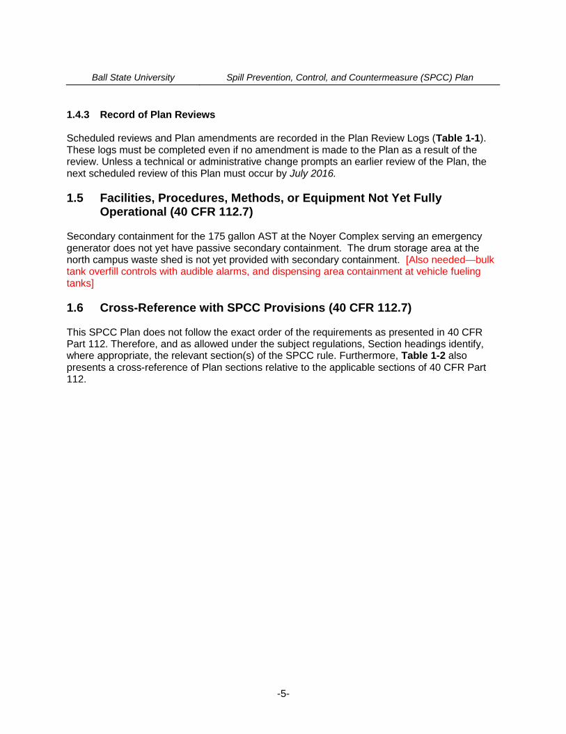
1.4.3 Record of Plan Reviews
Scheduled reviews and Plan amendments are recorded in the Plan Review Logs (Table 1-1).These logs must be completed even if no amendment is made to the Plan as a result of thereview. Unless a technical or administrative change prompts an earlier review of the Plan, thenext scheduled review of this Plan must occur by July 2016.
1.5 Facilities, Procedures, Methods, or Equipment Not Yet FullyOperational (40 CFR 112.7)
Secondary containment for the 175 gallon AST at the Noyer Complex serving an emergencygenerator does not yet have passive secondary containment. The drum storage area at thenorth campus waste shed is not yet provided with secondary containment. [Also needed—bulktank overfill controls with audible alarms, and dispensing area containment at vehicle fuelingtanks]
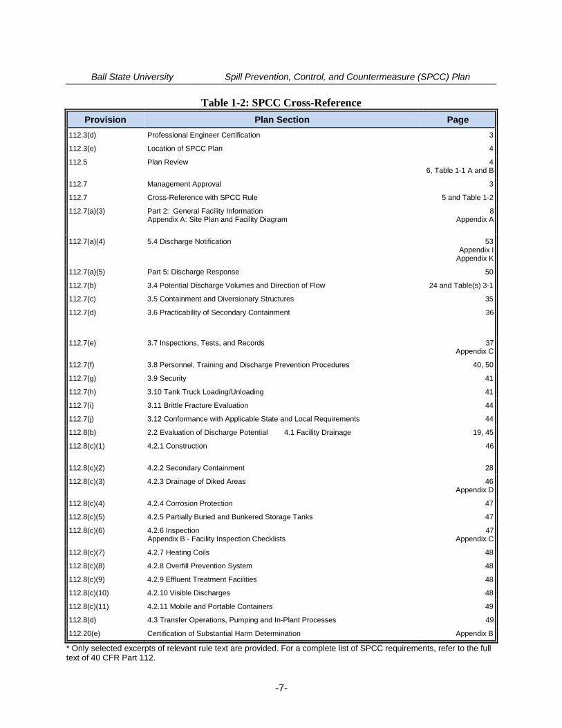
1.6 Cross-Reference with SPCC Provisions (40 CFR 112.7)
This SPCC Plan does not follow the exact order of the requirements as presented in 40 CFRPart 112. Therefore, and as allowed under the subject regulations, Section headings identify,where appropriate, the relevant section(s) of the SPCC rule. Furthermore, Table 1-2 alsopresents a cross-reference of Plan sections relative to the applicable sections of 40 CFR Part112.
Ball State University Spill Prevention, Control, and Countermeasure (SPCC) Plan
-6-
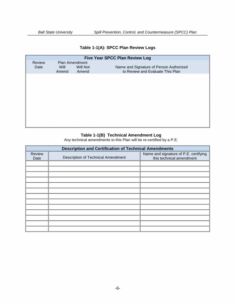
Table 1-1(A): SPCC Plan Review Logs
Five Year SPCC Plan Review LogReview
DatePlan Amendment
Name and Signature of Person Authorizedto Review and Evaluate This Plan
WillAmend
Will NotAmend
Table 1-1(B) Technical Amendment LogAny technical amendments to this Plan will be re-certified by a P.E.
Description and Certification of Technical AmendmentsReview
Date Description of Technical AmendmentName and signature of P.E. certifying
this technical amendment
Ball State University Spill Prevention, Control, and Countermeasure (SPCC) Plan
-7-
Table 1-2: SPCC Cross-Reference
Provision Plan Section Page
112.3(d) Professional Engineer Certification 3
112.3(e) Location of SPCC Plan 4
112.5 Plan Review 46, Table 1-1 A and B
112.7 Management Approval 3
112.7 Cross-Reference with SPCC Rule 5 and Table 1-2
112.7(a)(3) Part 2: General Facility InformationAppendix A: Site Plan and Facility Diagram
8Appendix A
112.7(a)(4) 5.4 Discharge Notification 53Appendix I
Appendix K
112.7(a)(5) Part 5: Discharge Response 50
112.7(b) 3.4 Potential Discharge Volumes and Direction of Flow 24 and Table(s) 3-1
112.7(c) 3.5 Containment and Diversionary Structures 35
112.7(d) 3.6 Practicability of Secondary Containment 36
112.7(e) 3.7 Inspections, Tests, and Records 37Appendix C
112.7(f) 3.8 Personnel, Training and Discharge Prevention Procedures 40, 50
112.7(g) 3.9 Security 41
112.7(h) 3.10 Tank Truck Loading/Unloading 41
112.7(i) 3.11 Brittle Fracture Evaluation 44
112.7(j) 3.12 Conformance with Applicable State and Local Requirements 44
112.8(b) 2.2 Evaluation of Discharge Potential 4.1 Facility Drainage 19, 45
112.8(c)(1) 4.2.1 Construction 46
112.8(c)(2) 4.2.2 Secondary Containment 28
112.8(c)(3) 4.2.3 Drainage of Diked Areas 46Appendix D
112.8(c)(4) 4.2.4 Corrosion Protection 47
112.8(c)(5) 4.2.5 Partially Buried and Bunkered Storage Tanks 47
112.8(c)(6) 4.2.6 InspectionAppendix B - Facility Inspection Checklists
47Appendix C
112.8(c)(7) 4.2.7 Heating Coils 48
112.8(c)(8) 4.2.8 Overfill Prevention System 48
112.8(c)(9) 4.2.9 Effluent Treatment Facilities 48
112.8(c)(10) 4.2.10 Visible Discharges 48
112.8(c)(11) 4.2.11 Mobile and Portable Containers 49
112.8(d) 4.3 Transfer Operations, Pumping and In-Plant Processes 49
112.20(e) Certification of Substantial Harm Determination Appendix B
* Only selected excerpts of relevant rule text are provided. For a complete list of SPCC requirements, refer to the fulltext of 40 CFR Part 112.
Ball State University Spill Prevention, Control, and Countermeasure (SPCC) Plan
-8-
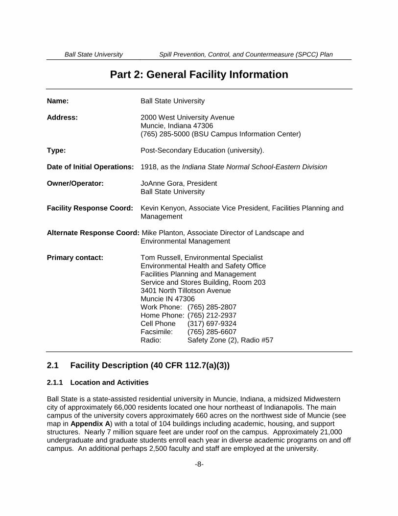
Part 2: General Facility Information
Name: Ball State University
Address: 2000 West University AvenueMuncie, Indiana 47306(765) 285-5000 (BSU Campus Information Center)
Type: Post-Secondary Education (university).
Date of Initial Operations: 1918, as the Indiana State Normal School-Eastern Division
Owner/Operator: JoAnne Gora, PresidentBall State University
Facility Response Coord: Kevin Kenyon, Associate Vice President, Facilities Planning andManagement
Alternate Response Coord: Mike Planton, Associate Director of Landscape andEnvironmental Management
Primary contact: Tom Russell, Environmental SpecialistEnvironmental Health and Safety OfficeFacilities Planning and ManagementService and Stores Building, Room 2033401 North Tillotson AvenueMuncie IN 47306Work Phone: (765) 285-2807Home Phone: (765) 212-2937Cell Phone (317) 697-9324Facsimile: (765) 285-6607Radio: Safety Zone (2), Radio #57
2.1 Facility Description (40 CFR 112.7(a)(3))
2.1.1 Location and Activities
Ball State is a state-assisted residential university in Muncie, Indiana, a midsized Midwesterncity of approximately 66,000 residents located one hour northeast of Indianapolis. The maincampus of the university covers approximately 660 acres on the northwest side of Muncie (seemap in Appendix A) with a total of 104 buildings including academic, housing, and supportstructures. Nearly 7 million square feet are under roof on the campus. Approximately 21,000undergraduate and graduate students enroll each year in diverse academic programs on and offcampus. An additional perhaps 2,500 faculty and staff are employed at the university.
Ball State University Spill Prevention, Control, and Countermeasure (SPCC) Plan
-9-
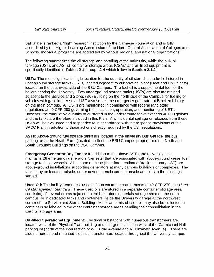
Ball State is ranked a “high” research institution by the Carnegie Foundation and is fullyaccredited by the Higher Learning Commission of the North Central Association of Colleges andSchools. Individual programs are accredited by various regional and national organizations.
The following summarizes the oil storage and handling at the university, while the bulk oiltankage (USTs and ASTs), container storage areas (CSAs) and oil-filled equipment isspecifically identified in Tables 2-1 through 2-4 which follow in Section 2.1.2:
USTs: The most significant single location for the quantity of oil stored is the fuel oil stored inunderground storage tanks (USTs) located adjacent to our physical plant (Heat and Chill plants)located on the southwest side of the BSU Campus. The fuel oil is a supplemental fuel for theboilers serving the University. Two underground storage tanks (USTs) are also maintainedadjacent to the Service and Stores (SV) Building on the north side of the Campus for fueling ofvehicles with gasoline. A small UST also serves the emergency generator at Bracken Libraryon the main campus. All USTs are maintained in compliance with federal (and state)regulations at 40 CFR 280 governing the installation, operation, and monitoring of USTs.However, the cumulative quantity of oil stored in the underground tanks exceeds 40,000 gallonsand the tanks are therefore included in this Plan. Any incidental spillage or releases from theseUSTs will be evaluated and responded to in accordance with the response provisions of thisSPCC Plan, in addition to those actions directly required by the UST regulations.
ASTs: Above-ground fuel storage tanks are located at the university Bus Garage, the busparking area, the Heath Farm (located north of the BSU Campus proper), and the North andSouth Grounds Buildings on the BSU Campus.
Emergency Generator Day Tanks: In addition to the above ASTs, the university alsomaintains 28 emergency generators (gensets) that are associated with above-ground diesel fuelstorage tanks or vessels. All but one of these (the aforementioned Bracken Library UST) areabove-ground installations supporting generators at many campus buildings or complexes. Thetanks may be located outside, under cover, in enclosures, or inside annexes to the buildingsserved.
Used Oil: The facility generates “used oil” subject to the requirements of 40 CFR 279, the UsedOil Management Standard. These used oils are stored in a separate container storage areaconsisting of several drums adjacent to the hazardous materials storage shed on the northcampus, or in dedicated tanks and containers inside the University garage at the northwestcorner of the Service and Stores Building. Minor amounts of used oil may also be collected incontainers so labeled in the other container storage areas pending their consolidation in theused oil storage area.
Oil-filled Operational Equipment: Electrical substations with numerous transformers arelocated west of the Physical Plant building and a larger installation west of the Carmichael Hallparking lot (north of the intersection of W. Euclid Avenue and N. Elizabeth Avenue). There arealso numerous pad-mounted electrical transformers located throughout the University campus

Ball State University Spill Prevention, Control, and Countermeasure (SPCC) Plan
-10-
that are the “wet-type” and contain dielectric fluid (oil). Also, a number of hydraulically operatedelevators are present serving many of the campus buildings.
Portable Containers: Totes or 55-gallon containers (drums) of oil may be stored at severalcampus locations. Most significant are the north waste shed and the container storage area(CSA) adjacent to it, the hazardous waste accumulation area in the Cooper Science Building,and the BSU Bus Garage. Normally, perhaps two (2) drums of dielectric oil are stored in theelectric shop shed at the Heath Farm north of the campus proper. There are also six (6) largedining facilities on the Campus, each of which utilize vegetable oils in their food preparationactivities which also entails handling of non-petroleum based oils and portable containers fortheir off-site reclamation by private vendors. Grease interceptors associated with the dining hallsare part of the wastewater collection system and are pumped out routinely, and the fresh andused oils are stored in 20-gallon mobile containers on wheeled dollies provided by the vendor.
Other Oil Handling: The University also handles, stores, and uses a variety of other petroleumproducts in the form of hydraulic oil, elevator oil, gear oil, lubricating oil, way oils, and similarpetroleum compounds for lubricating, hydraulic operations, and maintenance purposes. Anumber of greases of varying viscosity are also maintained for vehicle, dining hall, and othermaintenance uses. These are normally stored in containers of 55-gallon capacity or less. BallState University receives bulk oil products by common carrier tanker truck and drums by truck ortrailer. No rail service is involved in oil deliveries to the facility.
The University is open year round and emergency occurrences, including oil releases, are to bereported 24 hours per day through the University Public Safety (Police) Department at (28)5-1111 or 911. The appropriate BSU maintenance or emergency response personnel will then benotified for response. Outside emergency response authorities (City of Muncie and DelawareCounty Emergency Management Agency, the IDEM, NRC, or private contractors) will becontacted for assistance when necessary.
The Site Plan included in Appendix A of this Plan shows the location and layout of theUniversity and structures. The Facility Diagram (Figure A-2) shows the location of thefacilities, appurtenances, tanks, container storage areas, or equipment subject to this SPCCPlan through use of the included building key. Any minor or incidental oil storage or handlinglocations that are not included in the Table would normally involve the use of small quantities ofoil in containers of less than 55 gallon capacity, or similar to containers common for residentialuse. Regardless, any spillage of oil, regardless of the source, will be addressed through theresponse procedures established in this SPCC Plan or the associated BSU Spill ResponsePlan. Similarly, outside contractors, when working on BSU grounds, are to notify BSU of theiroil storage and handling practices to ensure they are consistent with the protections afforded bythis SPCC Plan.
Ball State University is located adjacent to predominantly residential areas, with some nearbyretail, and light commercial activities. Ball Memorial Hospital is located adjacent to theuniversity on the southwest area of the campus. The site has been in educational use sinceearly in the last century.
Ball State University Spill Prevention, Control, and Countermeasure (SPCC) Plan
-11-
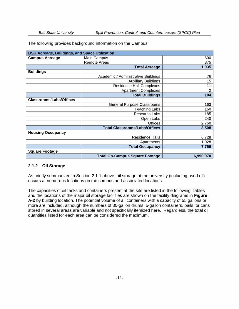
The following provides background information on the Campus:
BSU Acreage, Buildings, and Space UtilizationCampus Acreage Main Campus
Remote Areas600375
Total Acreage 1,035Buildings
Academic / Administrative Buildings 76Auxiliary Buildings 15
Residence Hall Complexes 11Apartment Complexes 2
Total Buildings 104Classrooms/Labs/Offices
General Purpose Classrooms 163Teaching Labs 160Research Labs 185
Open Labs 240Offices 2,760
Total Classrooms/Labs/Offices 3,508Housing Occupancy
Residence Halls 6,728Apartments 1,028
Total Occupancy 7,756Square Footage
Total On-Campus Square Footage 6,990,970
2.1.2 Oil Storage
As briefly summarized in Section 2.1.1 above, oil storage at the university (including used oil)occurs at numerous locations on the campus and associated locations.
The capacities of oil tanks and containers present at the site are listed in the following Tablesand the locations of the major oil storage facilities are shown on the facility diagrams in FigureA-2 by building location. The potential volume of all containers with a capacity of 55 gallons ormore are included, although the numbers of 30-gallon drums, 5-gallon containers, pails, or cansstored in several areas are variable and not specifically itemized here. Regardless, the total oilquantities listed for each area can be considered the maximum.

Ball State University Spill Prevention, Control, and Countermeasure (SPCC) Plan
-12-
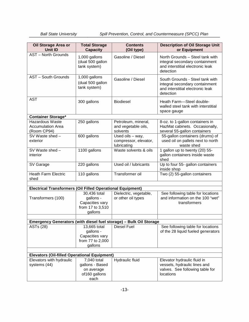
Table 2-1: Summary Table of Bulk Oil Tanks, Containers, or Equipment
Oil Storage Area orUnit ID
Total StorageCapacity
Contents(Oil type)
Description of Oil Storage Unitor Equipment
Bulk Storage Containers (Tanks)
Fuel Oil USTs
(Heat Plant)
180,000 gallons Fuel Oil (back-up forcoal and natural gasfired boilers)
Six (6), 30,000-gallon steeldouble-walled undergroundstorage tanks with protectivecoatings, catchment basins, andelectronic tank gauging (ATG).
Gasoline USTs
(SV Garage)16,000 gallons Unleaded gasoline. Two (2), 8,000-gallon fiberglass
underground storage tanks with(ATG), catchment basin, andoverfill prevention drop tubesand visual/audible overfill alarms.
Generator Fuel UST(Bracken Library)
550 gallon Diesel fuel One (1) 550-gallon fiberglassunderground storage tank withoverfill prevention drop tube,catchment basin, andlevelometer.
E-85 fuel AST
(SV Garage)500 gallons Unleaded gasoline
with ethanolSteel, double-walled tank anddispenser under canopy onGarage concrete fuel dispenserisland
SV Garage--used oil,ATF, and engine oiltanks
1100 gallons Used and virginengine oil and ATF
Four (4) 275-gallon steel tanks,located in concrete vaultcontainment on west side of SVGarage
SV Garage – Engine oilAST
275 gallons Engine oil/lubricant Steel, double-walled tank withinterstitial space gauge onconcrete floor slab (interior)
SV Biodiesel AST –north yard
1,000 gallons Biodiesel (B20)- buses Concrete, double-walled tankwith interstitial leak detection andoverfill alarm
SV Biodiesel AST –north yard
1,000 gallons Biodiesel (B2) - buses Steel, double-walled tank withinterstitial monitoring gauge
Ball State University Spill Prevention, Control, and Countermeasure (SPCC) Plan
-13-
Oil Storage Area orUnit ID
Total StorageCapacity
Contents(Oil type)
Description of Oil Storage Unitor Equipment
AST – North Grounds1,000 gallons(dual 500 gallontank system)
Gasoline / Diesel North Grounds – Steel tank withintegral secondary containmentand interstitial electronic leakdetection
AST – South Grounds 1,000 gallons
(dual 500 gallontank system)
Gasoline / Diesel South Grounds - Steel tank withintegral secondary containmentand interstitial electronic leakdetection
AST300 gallons Biodiesel Heath Farm—Steel double-
walled steel tank with interstitialspace gauge
Container Storage*Hazardous WasteAccumulation Area(Room CP94)
250 gallons Petroleum, mineral,and vegetable oils,solvents
8-oz. to 1-gallon containers inHazMat cabinets. Occasionally,several 55-gallon containers
SV Waste shed –exterior
600 gallons Used oils – way,compressor, elevator,lubricating
55-gallon containers (drums) ofused oil on pallets next to north
waste shedSV Waste shed –interior
1100 gallons Waste solvents & oils 1 gallon up to twenty (20) 55-gallon containers inside wasteshed
SV Garage 220 gallons Used oil / lubricants Up to four 55- gallon containersinside shop
Heath Farm Electricshed
110 gallons Transformer oil Two (2) 55-gallon containers
Electrical Transformers (Oil Filled Operational Equipment)
Transformers (100)30,436 total
gallons -Capacities varyfrom 17 to 3,510
gallons
Dielectric, vegetable,or other oil types
See following table for locationsand information on the 100 “wet”
transformers
Emergency Generators (with diesel fuel storage) – Bulk Oil StorageASTs (28) 13,665 total
gallons -Capacities varyfrom 77 to 2,000
gallons
Diesel Fuel See following table for locationsof the 28 liquid fueled generators
Elevators (Oil-filled Operational Equipment)Elevators with hydraulicsystems (44)
7,040 totalgallons - Based
on averageof160 gallons
each
Hydraulic fluid Elevator hydraulic fluid invessels, hydraulic lines andvalves. See following table forlocations

Ball State University Spill Prevention, Control, and Countermeasure (SPCC) Plan
-14-
* Refer to the BSU Chemical Hygiene Plan, Hazardous Waste Management Plan, and Spill ResponsePlans for information on the storage, handling, release prevention, and response procedures for smallercontainers of chemicals in science, technology, and art departments, some of which may contain “oils”.
Total Oil Storage: 256,146 gallons (maximum capacity): bulk storage and operationalequipment.
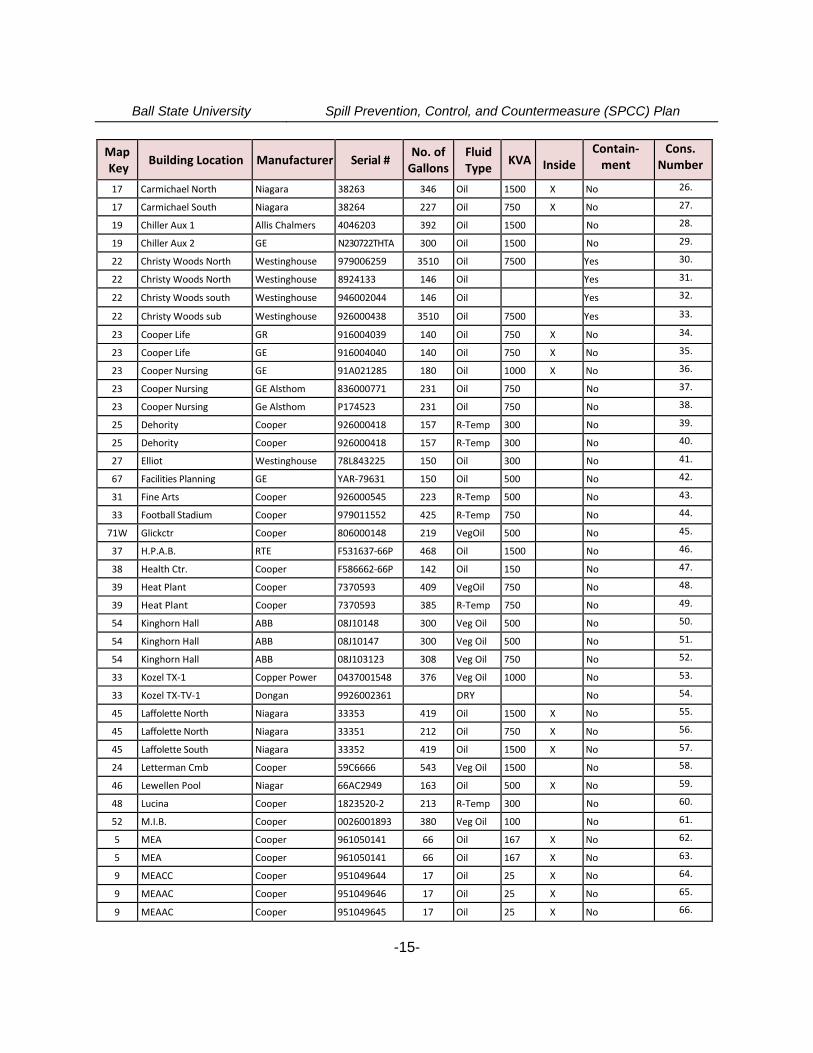
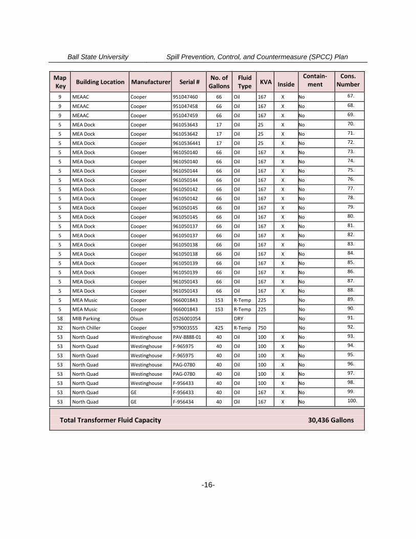
Table 2-2Oil-Filled Electric Transformers Table
(Cross-referenced by Building to BSU Campus Map Key)
BuildingsMapKey
Building Location Manufacturer Serial #No. of
GallonsFluidType
KVA InsideContain-
mentCons.
Number
40 Academy House RTE D483225-60P 180 Oil 300 No 1.
2 Admin Bldg. Maloney 77D460059 38 Oil 100 X No 2.
2 Admin. Bldg. Maloney 4046203 38 Oil 100 X No 3.
2 Admin. Bldg. Maloney 72F3298 38 Oil 100 X No 4.
3 Alumni Bldg Cooper D483227-60P 425 R-Temp 750 No 5.
5 Applied Tech Cooper 926000604 434 R-Temp 750 No 6.
6 Architecture Bldg Cooper 911113039 356 Oil 750 No 7.
6 Architecture Bldg Cooper 911113041 356 Oil 750 No 8.
83 Arena RTE F531637-66P 468 Oil 1500 No 9.
7 Art&Journalism Cooper 7370593 557 R-Temp 1500 No 10.
7 Art&Journalism Cooper 7370592 557 R-Temp 1500 No 11.
10 Ball Bldg G.E. 911113040 345 Oil 1500 No 12.
10 Ball Bldg G.E. 911113044 345 Oil 1500 No 13.
64 Bell Bldg RTE 911113043 363 R-Temp 1000 No 14.
64 Bell Bldg RTE 911113042 383 R-Temp 1000 No 15.
41S Bethelsub North Pauwells 926000477 2100 Oil 10000 Yes 16.
41S BethelsubNorthtc ABB 926000477 100 Oil Yes 17.
41 S Bethel Sub South Pau Wells 926000474 2100 Oil 10000 Yes 18.
41 S Bethel Sub South Tc ABB 926000603 100 Oil Yes 19.
47 Bracken Lib. Westinghouse 91A442999 654 Oil 3000 X No 20.
47 Bracken Lib. Westinghouse 91A480770 385 Oil 2500 X No 21.
15 Burkhardt GE 082529 115 Oil 300 No 22.
15 Burkhardt GE F4524 115 Oil 300 No 23.
16 Burris Cooper D483223-60P 345 R-Temp 1000 No 24.
69 Bus Parking Lot Cooper 951047885 183 VegOil 300 No 25.
Ball State University Spill Prevention, Control, and Countermeasure (SPCC) Plan
-15-
MapKey
Building Location Manufacturer Serial #No. of
GallonsFluidType
KVA InsideContain-
mentCons.
Number
17 Carmichael North Niagara 38263 346 Oil 1500 X No 26.
17 Carmichael South Niagara 38264 227 Oil 750 X No 27.
19 Chiller Aux 1 Allis Chalmers 4046203 392 Oil 1500 No 28.
19 Chiller Aux 2 GE N230722THTA 300 Oil 1500 No 29.
22 Christy Woods North Westinghouse 979006259 3510 Oil 7500 Yes 30.
22 Christy Woods North Westinghouse 8924133 146 Oil Yes 31.
22 Christy Woods south Westinghouse 946002044 146 Oil Yes 32.
22 Christy Woods sub Westinghouse 926000438 3510 Oil 7500 Yes 33.
23 Cooper Life GR 916004039 140 Oil 750 X No 34.
23 Cooper Life GE 916004040 140 Oil 750 X No 35.
23 Cooper Nursing GE 91A021285 180 Oil 1000 X No 36.
23 Cooper Nursing GE Alsthom 836000771 231 Oil 750 No 37.
23 Cooper Nursing Ge Alsthom P174523 231 Oil 750 No 38.
25 Dehority Cooper 926000418 157 R-Temp 300 No 39.
25 Dehority Cooper 926000418 157 R-Temp 300 No 40.
27 Elliot Westinghouse 78L843225 150 Oil 300 No 41.
67 Facilities Planning GE YAR-79631 150 Oil 500 No 42.
31 Fine Arts Cooper 926000545 223 R-Temp 500 No 43.
33 Football Stadium Cooper 979011552 425 R-Temp 750 No 44.
71W Glickctr Cooper 806000148 219 VegOil 500 No 45.
37 H.P.A.B. RTE F531637-66P 468 Oil 1500 No 46.
38 Health Ctr. Cooper F586662-66P 142 Oil 150 No 47.
39 Heat Plant Cooper 7370593 409 VegOil 750 No 48.
39 Heat Plant Cooper 7370593 385 R-Temp 750 No 49.
54 Kinghorn Hall ABB 08J10148 300 Veg Oil 500 No 50.
54 Kinghorn Hall ABB 08J10147 300 Veg Oil 500 No 51.
54 Kinghorn Hall ABB 08J103123 308 Veg Oil 750 No 52.
33 Kozel TX-1 Copper Power 0437001548 376 Veg Oil 1000 No 53.
33 Kozel TX-TV-1 Dongan 9926002361 DRY No 54.
45 Laffolette North Niagara 33353 419 Oil 1500 X No 55.
45 Laffolette North Niagara 33351 212 Oil 750 X No 56.
45 Laffolette South Niagara 33352 419 Oil 1500 X No 57.
24 Letterman Cmb Cooper 59C6666 543 Veg Oil 1500 No 58.
46 Lewellen Pool Niagar 66AC2949 163 Oil 500 X No 59.
48 Lucina Cooper 1823520-2 213 R-Temp 300 No 60.
52 M.I.B. Cooper 0026001893 380 Veg Oil 100 No 61.
5 MEA Cooper 961050141 66 Oil 167 X No 62.
5 MEA Cooper 961050141 66 Oil 167 X No 63.
9 MEACC Cooper 951049644 17 Oil 25 X No 64.
9 MEAAC Cooper 951049646 17 Oil 25 X No 65.
9 MEAAC Cooper 951049645 17 Oil 25 X No 66.
Ball State University Spill Prevention, Control, and Countermeasure (SPCC) Plan
-16-
MapKey
Building Location Manufacturer Serial #No. of
GallonsFluidType
KVA InsideContain-
mentCons.
Number
9 MEAAC Cooper 951047460 66 Oil 167 X No 67.
9 MEAAC Cooper 951047458 66 Oil 167 X No 68.
9 MEAAC Cooper 951047459 66 Oil 167 X No 69.
5 MEA Dock Cooper 961053643 17 Oil 25 X No 70.
5 MEA Dock Cooper 961053642 17 Oil 25 X No 71.
5 MEA Dock Cooper 9610536441 17 Oil 25 X No 72.
5 MEA Dock Cooper 961050140 66 Oil 167 X No 73.
5 MEA Dock Cooper 961050140 66 Oil 167 X No 74.
5 MEA Dock Cooper 961050144 66 Oil 167 X No 75.
5 MEA Dock Cooper 961050144 66 Oil 167 X No 76.
5 MEA Dock Cooper 961050142 66 Oil 167 X No 77.
5 MEA Dock Cooper 961050142 66 Oil 167 X No 78.
5 MEA Dock Cooper 961050145 66 Oil 167 X No 79.
5 MEA Dock Cooper 961050145 66 Oil 167 X No 80.
5 MEA Dock Cooper 961050137 66 Oil 167 X No 81.
5 MEA Dock Cooper 961050137 66 Oil 167 X No 82.
5 MEA Dock Cooper 961050138 66 Oil 167 X No 83.
5 MEA Dock Cooper 961050138 66 Oil 167 X No 84.
5 MEA Dock Cooper 961050139 66 Oil 167 X No 85.
5 MEA Dock Cooper 961050139 66 Oil 167 X No 86.
5 MEA Dock Cooper 961050143 66 Oil 167 X No 87.
5 MEA Dock Cooper 961050143 66 Oil 167 X No 88.
5 MEA Music Cooper 966001843 153 R-Temp 225 No 89.
5 MEA Music Cooper 966001843 153 R-Temp 225 No 90.
58 MIB Parking Olsun 0526001054 DRY No 91.
32 North Chiller Cooper 979003555 425 R-Temp 750 No 92.
53 North Quad Westinghouse PAV-8888-01 40 Oil 100 X No 93.
53 North Quad Westinghouse F-965975 40 Oil 100 X No 94.
53 North Quad Westinghouse F-965975 40 Oil 100 X No 95.
53 North Quad Westinghouse PAG-0780 40 Oil 100 X No 96.
53 North Quad Westinghouse PAG-0780 40 Oil 100 X No 97.
53 North Quad Westinghouse F-956433 40 Oil 100 X No 98.
53 North Quad GE F-956433 40 Oil 167 X No 99.
53 North Quad GE F-956434 40 Oil 167 X No 100.
Total Transformer Fluid Capacity 30,436 Gallons
Ball State University Spill Prevention, Control, and Countermeasure (SPCC) Plan
-17-
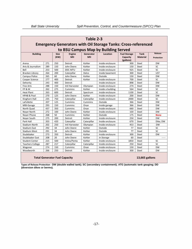
Table 2-3Emergency Generators with Oil Storage Tanks: Cross-referenced
to BSU Campus Map by Building ServedBuilding Size
(KW)Engine
MfrGenerator
MfrLocation Fuel Storage
Capacity(gallons)
TankMaterial
Release
Protection
Arena 271 250 Detroit Kohler Inside enclosure 300 Steel DW
Arts & Journalism 289 150 John Deere Kohler Inside enclosure 150 Steel SC
Bell 253 500 DDC-MTU Kohler Inside enclosure 925 Steel SC
Bracken Library 264 200 Caterpillar Delco Inside basement 300 Steel UST
Campus Police 265 60 John Deere Kohler Outside 150 Steel DW
Cooper Science 277 400 Detroit Kohler Inside enclosure 700 Steel SC
Dehority 243 400 Detroit Inside enclosure 898 Steel DW
Fine Arts 288 150 Intl Harvester Olympian Inside enclosure 274 Steel DW
FP & M 262 275 Cummins Kohler Inside a building 564 Steel SC
Heat Plant 263 600 Detroit Spectrum Inside enclosure 1100 Steel SC
HPAB & Pool 270 125 John Deere Kohler Inside enclosure 200 Steel DW
Kinghorn Hall 235 750 Caterpillar Caterpillar Inside enclosure 2000 Steel SC
LaFollette 207 125 Cummins Cummins Outside 366 Steel DW
MIB-Garage 293 150 Cummins Onan Inside garage 366 Steel DW
North Quad 437 350 Cummins Onan Inside enclosure 660 Steel DW
Noyer North 272 100 John Deere Kohler Inside enclosure 100 Steel DW
Noyer Phone 268 50 Cummins Kohler Outside 175 Steel None
Noyer South 275 200 Detroit Kohler Inside enclosure 250 Steel DW
Park Hall 203 420 Caterpillar Caterpillar Inside enclosure 670 Steel Dike; DW
Stadium-North 202 250 Intl Harvester Olympian Inside enclosure 453 Steel DW
Stadium-East 292 34 John Deere Kohler Outside 77 Steel SC
Stadium-West 291 34 John Deere Kohler Outside 77 Steel SC
Studebaker 273 350 Detroit Kohler Inside enclosure 300 Steel DW
Studebaker East 208 20 John Deere Kohler In Storage 60 Steel -----
Student Center 215 500 Volvo/Penta Kohler Inside enclosure 1850 Steel SC
Teachers College 287 217 Caterpillar Caterpillar Inside enclosure 250 Steel SC
Wagoner 274 150 Cummins Onan Inside enclosure 150 Steel DW
Woodworth 266 250 Detroit Kohler Inside enclosure 300 Steel DW
Total Generator Fuel Capacity 13,665 gallons
Types of Release Protection - DW (double walled tank); SC (secondary containment); ATG (automatic tank gauging; DD(diversion dikes or berms).
Ball State University Spill Prevention, Control, and Countermeasure (SPCC) Plan
-18-
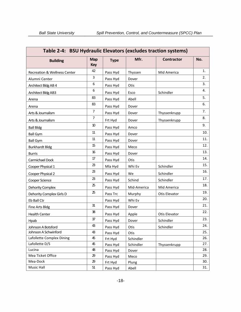
Table 2-4: BSU Hydraulic Elevators (excludes traction systems)
Building MapKey
Type Mfr. Contractor No.
Recreation & Wellness Center 42 Pass Hyd Thyssen Mid America 1.
Alumni Center 3 Pass Hyd Dover 2.
Architect Bldg AB 4 6 Pass Hyd Otis 3.
Architect Bldg AB36
Pass Hyd Esco Schindler4.
Arena 83 Pass Hyd Abell 5.
Arena83
Pass Hyd Dover6.
Arts & Journalism 7 Pass Hyd Dover Thyssenkrupp 7.
Arts & Journalism7
Frt Hyd Dover Thyssenkrupp8.
Ball Bldg10
Pass Hyd Amco9.
Ball Gym 11 Pass Hyd Dover 10.
Ball Gym 11 Pass Hyd Dover 11.
Burkhardt Bldg 15 Pass Hyd Meco 12.
Burris 16 Pass Hyd Dover 13.
Carmichael Dock 17 Pass Hyd Otis 14.
Cooper Physical 1 23 Mla Hyd Whi Ev Schindler 15.
Cooper Physical 223
Pass Hyd We Schindler16.
Cooper Science 23 Pass Hyd Schind Schindler 17.
Dehority Complex25
Pass Hyd Mid-America Mid America18.
Dehority Complex Girls D 25 Pass Trc Murphy Otis Elevator 19.
Eb Ball Ctr Pass Hyd Whi Ev 20.
Fine Arts Bldg 31 Pass Hyd Dover 21.
Health Center38
Pass Hyd Apple Otis Elevator22.
Hpab 37 Pass Hyd Dover Schindler 23.
Johnson A Botsford 43 Pass Hyd Otis Schindler 24.
Johnson A Schwinford 43 Pass Hyd Otis 25.
Lafollette Complex Dining 45 Frt Hyd Schindler 26.
Lafollette D/S 45 Pass Hyd Schindler Thyssenkrupp 27.
Lucina 48 Pass Hyd Dover 28.
Mea Ticket Office 29 Pass Hyd Meco 29.
Mea-Dock 29 Frt Hyd Plung 30.
Music Hall 51 Pass Hyd Abell 31.
Ball State University Spill Prevention, Control, and Countermeasure (SPCC) Plan
-19-
Building MapKey
Type Mfr. Contractor
North Quad 1 53 Pass Hyd Wht Ev 32.
North Quad 2 53 Pass Hyd W Evan 33.
North Quad 3 53 Pass Hyd Otis 34.
Noyer Bldg Dock 55 Frt Hyd Millar Schindler 35.
Pruis Hall 62 Pass Hyd Meco 36.
Robert Bell Bldg 64 Pass Hyd Esco 37.
Stadium 33 Pass Hyd Dover Otis Elevator 38.
West Quad 80 Frt Hyd Dover Schindler 39.
Whitinger 81 Pass Hyd Schind 40.
Woodworth Hall 1 E 82 Pass Hyd Dover 41.
Woodworth Hall 2 82 Pass Hyd Dover 42.
Mckinley Parking Garage #1 NW 58 Pass Hyd Schindler Schindler 43.
Music 52 Pass Hyd Schindler Schindler E 44.
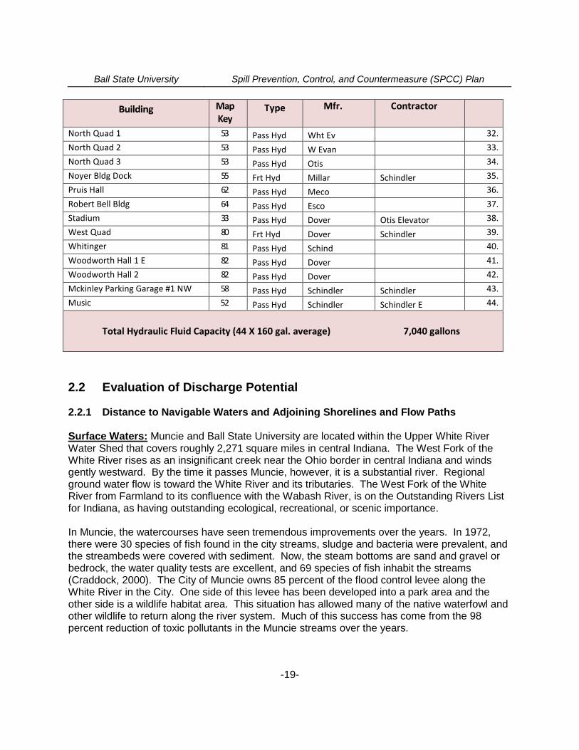
Total Hydraulic Fluid Capacity (44 X 160 gal. average) 7,040 gallons
2.2 Evaluation of Discharge Potential
2.2.1 Distance to Navigable Waters and Adjoining Shorelines and Flow Paths
Surface Waters: Muncie and Ball State University are located within the Upper White RiverWater Shed that covers roughly 2,271 square miles in central Indiana. The West Fork of theWhite River rises as an insignificant creek near the Ohio border in central Indiana and windsgently westward. By the time it passes Muncie, however, it is a substantial river. Regionalground water flow is toward the White River and its tributaries. The West Fork of the WhiteRiver from Farmland to its confluence with the Wabash River, is on the Outstanding Rivers Listfor Indiana, as having outstanding ecological, recreational, or scenic importance.
In Muncie, the watercourses have seen tremendous improvements over the years. In 1972,there were 30 species of fish found in the city streams, sludge and bacteria were prevalent, andthe streambeds were covered with sediment. Now, the steam bottoms are sand and gravel orbedrock, the water quality tests are excellent, and 69 species of fish inhabit the streams(Craddock, 2000). The City of Muncie owns 85 percent of the flood control levee along theWhite River in the City. One side of this levee has been developed into a park area and theother side is a wildlife habitat area. This situation has allowed many of the native waterfowl andother wildlife to return along the river system. Much of this success has come from the 98percent reduction of toxic pollutants in the Muncie streams over the years.
Ball State University Spill Prevention, Control, and Countermeasure (SPCC) Plan
-20-
Local surface water drainage on the main BSU Campus is largely accommodated by CardinalCreek which traverses much of the campus. The Creek starts as a developed spring just northof Park Hall that impounds, or ponds, at that location. The Park Hall pond and other storm waterdrainage then proceeds to the north/northwest beneath Neely Road and beyond the HealthCenter, after which it maintains a surface flow until reaching the Worthen Stadium parking lots.It is then conveyed subsurface through a large box culvert heading to the north/northwest whichis joined on its route by catch basin drains serving the paved parking areas around WorthenArena and other structures. The Creek again surfaces at the outlet to the impoundment calledthe “Duck Pond” on the north and east sides of McKinley Avenue, just south of the tennis courts.This impoundment serves as a reservoir for other surface and subsurface drainage from thecampus. The pond overflow is then channeled beneath the road to the other (west) side ofMcKinley Avenue where another impoundment (Duck Pond 2 or too) is maintained. Thedischarge from these serial impoundments is to Yorktown-Prairie Creek which proceedswest/southwest, eventually discharging to the White River on the west side of Yorktown,Indiana. Numerous storm water catch basins, curbside drain grates, and drainage swales onthe campus direct precipitation to the Cardinal Creek surface water drainage system throughoutits course across the campus.
The south portion of the main Ball State University campus (south of Riverside Avenue), as wellas this general vicinity of Muncie, is also served by sanitary and storm sewers. Surface waterdrainage in this area of the campus is predominantly to the south/southwest via overland flow.However, the subsurface storm water collection and drainage system conveys surface water tothe north and east where it discharges to Cardinal Creek and the related surface impoundmentsor “ponds” described above.
Accordingly, the possibility of oil reaching a surface waterway from a release or spill--eitherdirectly or through storm sewers is present. The threat of an oil release accessing a sanitary orcombined sewer, being transported to the Muncie POTW, and passing through the treatmentworks to the White River discharge point is also a possibility.
The northern portions of the Ball State campus (north of McGalliard Avenue), including thephysical plant Service and Stores (SV) building and the Heath Farm, drain to unnamed ditchesheading to the northwest to receiving waters named Eagle Branch of Jakes Creek. Jakes Creeklater joins with Killbuck Creek before its confluence with the White River near Anderson,Indiana. Ball State University maintains an NPDES Permit for the storm water discharge fromthis area of the campus, as well as for the surface water discharge from our coal storage yardlocated in this area.
The Ball State University Campus is designated as a Municipal Separate Sanitary Sewer (MS4)facility by the IDEM under its General Permit program and storm water drainage and quality iscontrolled through a Storm Water Quality Management Plan (SWQMP).
Ground (Subsurface) Waters: The Ball State University campus lies in the Tipton Till Plainphysiographic unit of the State of Indiana with the unconsolidated natural deposits in the vicinityof the campus being glacial tills. Tills consist of a heterogeneous mixture of clay, silt, sand andsome gravel with scattered cobbles and boulders. Lenses or deposits of sand and gravel
Ball State University Spill Prevention, Control, and Countermeasure (SPCC) Plan
-21-
interbedded within the tills is common. The glacial drift thickness is approximately 70 feet in thisarea, with limestone and dolomite bedrock at an elevation of approximately 875 feet MSL. Thetopographic elevation of the main BSU campus varies from 930 feet mean sea level (MSL) to945 feet MSL.
Studies and excavations have shown a “perched” water table or saturated soils across thecampus at an approximate depth of 10 feet below the surface with a second, lower aquifer, atdepths generally greater than 20 feet. Topsoil is of the Blount Silt Loam series. The Blountseries consists of very deep soils that are moderately deep or deep to dense till. They aresomewhat poorly drained, slowly permeable soils. These soils are on till plains and have slopesranging from 0 to 6 percent.
The BSU Campus is not located within a Wellhead Protection Zone, and the relatively lowoverall permeability of the overlying soils above the low-yield and discontinuous shallow groundwater lenses, generally 8 to 18 feet below ground surface, would not lend themselves to director rapid contamination of ground water from oil releases at the surface. Sustained or significantreleases could, however, impact the subsurface water quality--if not promptly addressedthrough cleanup and remediation.
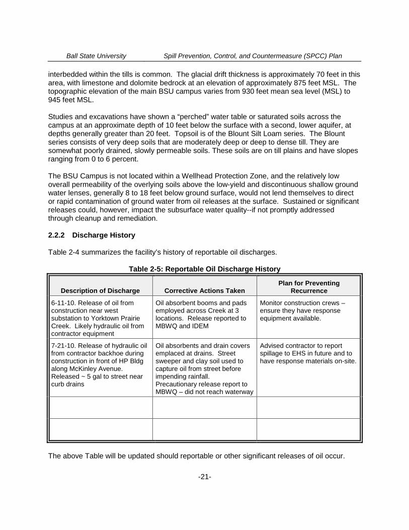
2.2.2 Discharge History
Table 2-4 summarizes the facility’s history of reportable oil discharges.
Table 2-5: Reportable Oil Discharge History
Description of Discharge Corrective Actions TakenPlan for Preventing
Recurrence
6-11-10. Release of oil fromconstruction near westsubstation to Yorktown PrairieCreek. Likely hydraulic oil fromcontractor equipment
Oil absorbent booms and padsemployed across Creek at 3locations. Release reported toMBWQ and IDEM
Monitor construction crews –ensure they have responseequipment available.
7-21-10. Release of hydraulic oilfrom contractor backhoe duringconstruction in front of HP Bldgalong McKinley Avenue.Released ~ 5 gal to street nearcurb drains
Oil absorbents and drain coversemplaced at drains. Streetsweeper and clay soil used tocapture oil from street beforeimpending rainfall.Precautionary release report toMBWQ – did not reach waterway
Advised contractor to reportspillage to EHS in future and tohave response materials on-site.
The above Table will be updated should reportable or other significant releases of oil occur.
Ball State University Spill Prevention, Control, and Countermeasure (SPCC) Plan
-22-
PART 3: Discharge Prevention - General SPCC Provisions
The following equipment is provided, or measures implemented, to prevent oil discharges duringthe handling, use, or transfer of oil products at BSU. Employees involved in the storage, use, orhandling of oil have received training in the proper implementation of these measures.
3.1 Compliance with Applicable Requirements (40 CFR 112.7(a)(2))
The vehicle fueling ASTs all have double-wall construction and are inspected following a regularschedule in accordance with the Steel Tank Institute (STI) SP-001, UL 142, or AmericanPetroleum Institute (API) 653 tank inspection standards as described in this Plan. Any leakagefrom the primary container would be detected through the continuous electronic monitoring ofthe interstitial space with associated alarms, or through observation of the visible gauges. Anyleakage from the secondary shell, piping, or valves would be detected visually during scheduledvisual inspections by facility personnel.
The BSU Garage USTs are both equipped with automatic tank gauging (ATG), with leakdetection tests being automatically performed weekly. The ATG systems are manufactured byVeeder-Root and are maintained by Gasoline Equipment Service or Jim Allen Maintenance.The vehicle fueling USTs are operated in compliance with 40 CFR 280 and the parallel IDEMstandards. These USTs are provided with catchment basins, drop-tube type overfill preventionvalves, and auditory and visual overfill alarms. The small UST serving the Bracken Libraryemergency generator is provided with a catchment basin, drop-tube type overfill preventionvalve, and a tank level gauge. The tank is of fiberglass construction.
The six (6) 30,000-gallon USTs at the Heat Plant are for on-site consumption and are not,therefore, subject to the UST standards. Regardless, they are installed and monitored inaccordance with those standards and in a manner to prevent releases to the soil or waters ofthe state. These tanks are fiberglass (FRP) clad, double wall, fabricated of A36 carbon steel inaccordance with the requirements of UL-58. The primary containment shell is 3/8-inch steel.An interstitial monitoring system is provided. Each tank is clad with a coating of resin andchopped strand glass fibers applied to a thickness of 100 mils minimum, over 100% of thetank’s surfaces. Cladding conforms to the STI Permatank® procedure (UL-1746). The tank isequipped with a Veeder-Root console providing fuel management functions with inventorycontrol, interstitial space leak monitoring, tank leak sensing, and fuel line leak detection.
The numerous electric transformers serving the campus (see Table 2-2), with the exception ofseveral at the Bethel and Christy Woods substations, are not provided with physical secondarycontainment. Secondary containment is not a practical means of spill control due to theelectrical hazards presented by impounding oils and water around live transformers andswitching equipment. Electrical transformers are “oil-filled operating equipment” under 40 CFR112 and are not, therefore, required to have full secondary equipment. In most cases, however,the transformers are installed on concrete pads allowing observation for any leakage, and aresurrounded by gravel at an approximate 4-inch thickness that would serve to contain or retardany release of dielectric fluid from the transformers. Active secondary containment would alsobe employed in the event of any weepage, leakage, or significant release from the transformers.
Ball State University Spill Prevention, Control, and Countermeasure (SPCC) Plan
-23-
A significant fluid release would result in overheating and failure of the transformer resulting in apower loss that would be quickly reported. The BSU High Voltage staff has been informed tocontact the University Police or the EHS Office to report any release of dielectric fluid from theseunits. The High Voltage staff thoroughly inspects each transformer quarterly for operation,thermal condition, dielectric oil level, and any leakage or damage. These inspections arerecorded on inspection logs that are maintained by the High Voltage Department.
The emergency generator day tanks (see Table 2-3) are equipped with secondary containmentof some means (double-walled tank or containment vault). Further, in most cases, these tanksare integral components of the emergency generators themselves and are not free-standingbulk storage tanks; rather, they comprise a generator set or “genset”. BSU electricians performtest runs weekly on the generators. At that time, they also check the fuel levels and check forany fuel leakage around the gensets. These inspections are recorded on a log sheet kept in thegenerator enclosure or room. A contracted fuel vendor is notified if the genset fuel tanks needreplenishing. The fuel supplier is to follow the BSU fuel delivery procedures outlined in Section3.10 of this Plan.
The hydraulically operated passenger and freight elevators (see Table 2-4) are installed withsub-grade concrete slab shafts (vaults) that serve as secondary containment in the event of ahydraulic line or valve leak. Hydraulic elevator reservoirs are generally located in roomsseparate from the elevator shaft (which usually resides in a pit). Oil reservoirs sometimes havethe potential to leak into floor drains leading to ejector pumps and henceforth to sewers.However, the hydraulic elevators are “oil-filled operating equipment” under 40 CFR 112 and arenot, therefore, required to have full secondary containment.
The food service facilities on campus utilize grease canisters to temporarily store waste oilassociated with cooking processes. These containers are 20 gallons in capacity to accumulatefats, grease, and cooking oils and are typically staged under roof at the rear loading dock of theBSU food service buildings, in the building basements, or in storage rooms pending removal bythe private vendor. The canisters are picked up weekly by the vendor and any container spillwould most likely solidify or congeal before reaching nearby storm sewers. Grease interceptorsare also installed on the wastewater drains from most of the significant campus buildings thathouse food service establishments. These vary in capacity of 500 to 3,600 gallons. Theseinterceptors are considered wastewater treatment or flow-through process tanks and are notsubject to this SPCC Plan. The interceptors are cleaned at least quarterly by an IDEM licensedwastewater hauler for proper off-site disposal as required by the Muncie BWQ.
However, as all of the university’s oil storage containers, tanks, or oil handling areas (ASTs,generator day tanks, transformers, north container storage area) are not provided with passivesecondary containment for either: (1) the fuel filling/dispensing areas; or, (2) the tanks orcontainers themselves, provisions are made for active containment measures at the university.While BSU is not making any “impracticability determinations” for secondary containment forbulk or general oil storage devices or areas, “active secondary containment” is provided forspecified container (55-gallon drum) storage, dispensing areas, and small “day” tanks. Thosetanks or dispensing areas are subject to the BSU Spill Response Plan, as summarized inSection 5 of this Plan, that includes the means for the active and timely containment and
Ball State University Spill Prevention, Control, and Countermeasure (SPCC) Plan
-24-
response to any incidental or catastrophic releases of oil (or other substances) that may occuron the BSU campus.
3.2 Facility Layout Diagram (40 CFR 112.7(a)(3))
Figure A-1 in Appendix A shows the general location of the university. Figure A-2 inAppendix A presents a layout of the university with a building cross-reference. As requiredunder 40 CFR 112.7(a)(3), the facility diagram, in conjunction with the Tables within this SPCCPlan indicates the proximate location of ASTs, USTs, oil container storage areas, and transferareas on the campus. The large number of genset tanks, transformers, and hydraulically-operated equipment prevents indicating their precise location on a map or facility layout.Accordingly, the units are located by building name or number. The building locations,capacities, and contents of the various oil containers or tanks were provided in the variousTables included in Section 2 of this SPCC Plan.
3.3 Spill Reporting (40 CFR 112.7(a)(4))
The discharge notification form included in Appendix I will be completed, at least in part, upondetection of a discharge and prior to reporting a spill to the proper notification contacts.However, full completion of the form should not delay the required reporting to regulatory orresponse agencies. Spill incidents may first be reported through the University PoliceDepartment, to BSU Facilities Planning and Management, or to the BSU EHS Office.Regardless, the BSU Environmental Specialist will ensure that any required reporting toregulatory agencies or response entities is completed when required or advisable.
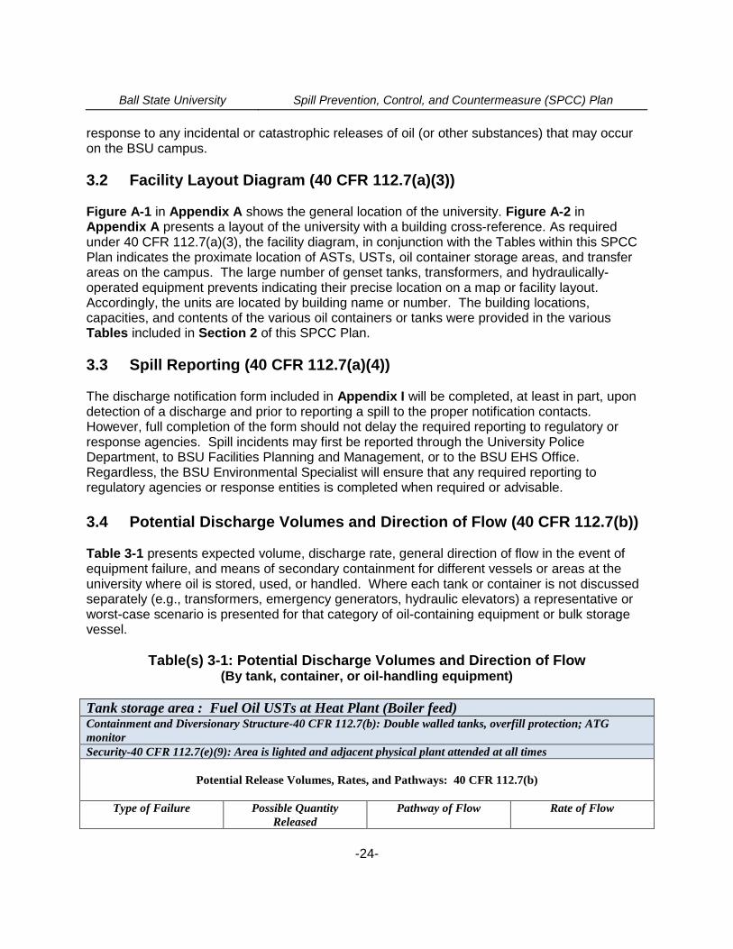
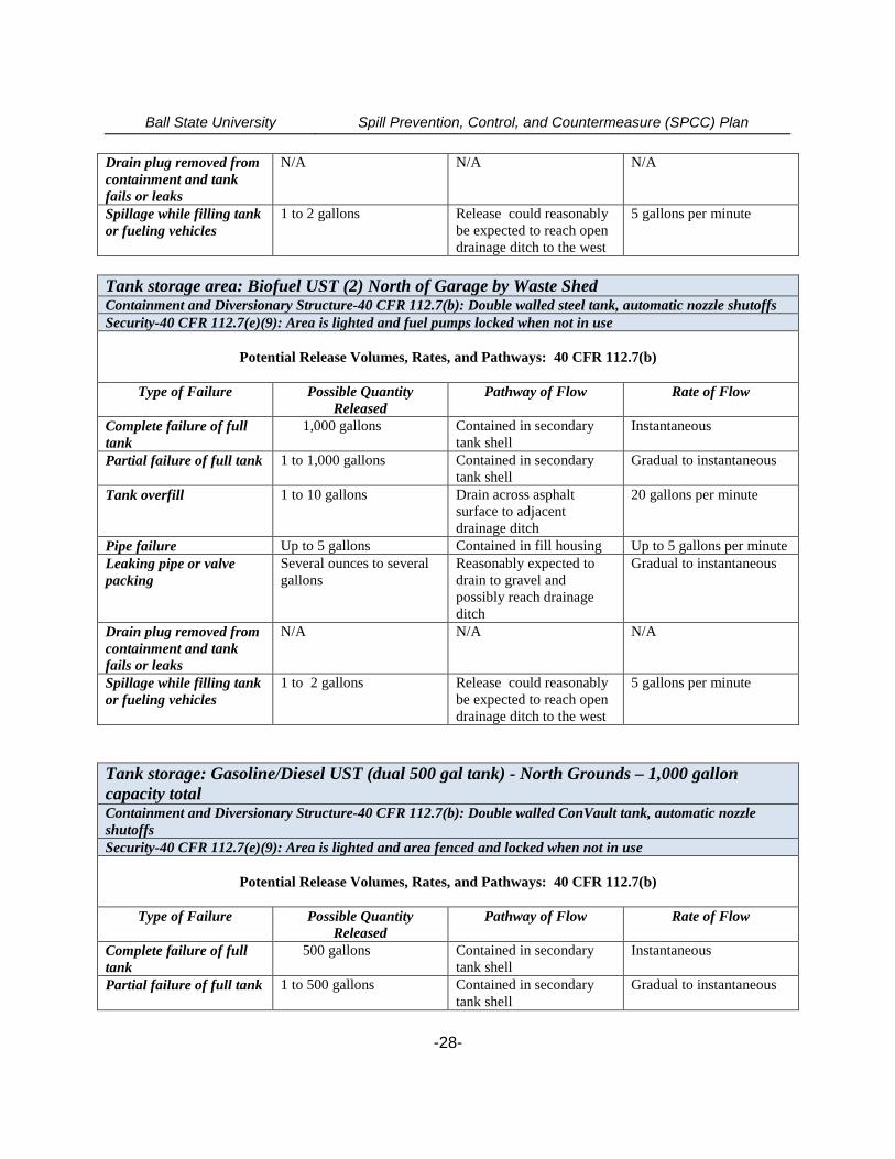
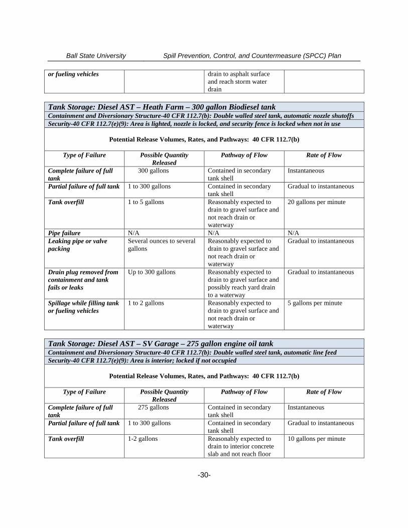
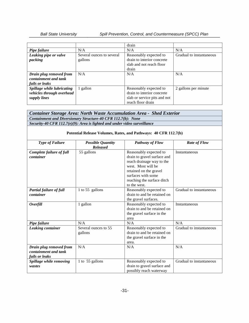
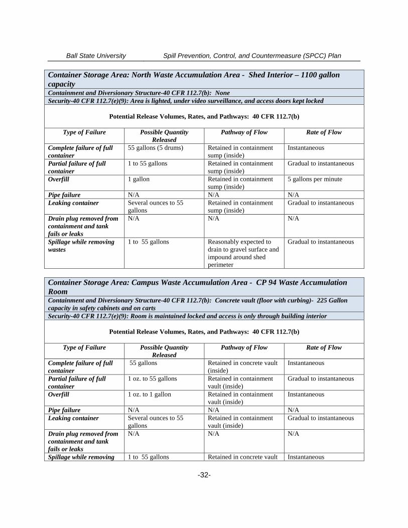
3.4 Potential Discharge Volumes and Direction of Flow (40 CFR 112.7(b))
Table 3-1 presents expected volume, discharge rate, general direction of flow in the event ofequipment failure, and means of secondary containment for different vessels or areas at theuniversity where oil is stored, used, or handled. Where each tank or container is not discussedseparately (e.g., transformers, emergency generators, hydraulic elevators) a representative orworst-case scenario is presented for that category of oil-containing equipment or bulk storagevessel.
Table(s) 3-1: Potential Discharge Volumes and Direction of Flow(By tank, container, or oil-handling equipment)
Tank storage area : Fuel Oil USTs at Heat Plant (Boiler feed)Containment and Diversionary Structure-40 CFR 112.7(b): Double walled tanks, overfill protection; ATGmonitorSecurity-40 CFR 112.7(e)(9): Area is lighted and adjacent physical plant attended at all times
Potential Release Volumes, Rates, and Pathways: 40 CFR 112.7(b)
Type of Failure Possible QuantityReleased
Pathway of Flow Rate of Flow
Ball State University Spill Prevention, Control, and Countermeasure (SPCC) Plan
-25-
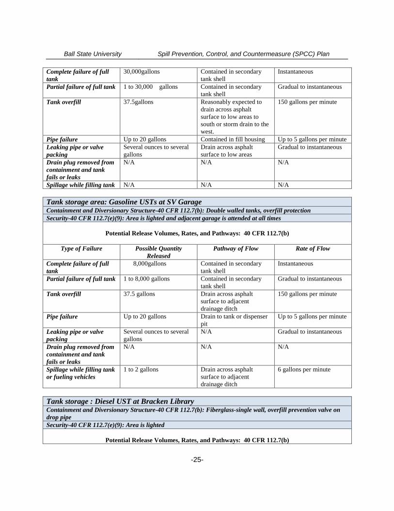
Complete failure of fulltank
30,000gallons Contained in secondarytank shell
Instantaneous
Partial failure of full tank 1 to 30,000 gallons Contained in secondarytank shell
Gradual to instantaneous
Tank overfill 37.5gallons Reasonably expected todrain across asphaltsurface to low areas tosouth or storm drain to thewest.
150 gallons per minute
Pipe failure Up to 20 gallons Contained in fill housing Up to 5 gallons per minuteLeaking pipe or valvepacking
Several ounces to severalgallons
Drain across asphaltsurface to low areas
Gradual to instantaneous
Drain plug removed fromcontainment and tankfails or leaks
N/A N/A N/A
Spillage while filling tank N/A N/A N/A
Tank storage area: Gasoline USTs at SV GarageContainment and Diversionary Structure-40 CFR 112.7(b): Double walled tanks, overfill protectionSecurity-40 CFR 112.7(e)(9): Area is lighted and adjacent garage is attended at all times
Potential Release Volumes, Rates, and Pathways: 40 CFR 112.7(b)
Type of Failure Possible QuantityReleased
Pathway of Flow Rate of Flow
Complete failure of fulltank
8,000gallons Contained in secondarytank shell
Instantaneous
Partial failure of full tank 1 to 8,000 gallons Contained in secondarytank shell
Gradual to instantaneous
Tank overfill 37.5 gallons Drain across asphaltsurface to adjacentdrainage ditch
150 gallons per minute
Pipe failure Up to 20 gallons Drain to tank or dispenserpit
Up to 5 gallons per minute
Leaking pipe or valvepacking
Several ounces to severalgallons
N/A Gradual to instantaneous
Drain plug removed fromcontainment and tankfails or leaks
N/A N/A N/A
Spillage while filling tankor fueling vehicles
1 to 2 gallons Drain across asphaltsurface to adjacentdrainage ditch
6 gallons per minute
Tank storage : Diesel UST at Bracken LibraryContainment and Diversionary Structure-40 CFR 112.7(b): Fiberglass-single wall, overfill prevention valve ondrop pipeSecurity-40 CFR 112.7(e)(9): Area is lighted
Potential Release Volumes, Rates, and Pathways: 40 CFR 112.7(b)
Ball State University Spill Prevention, Control, and Countermeasure (SPCC) Plan
-26-
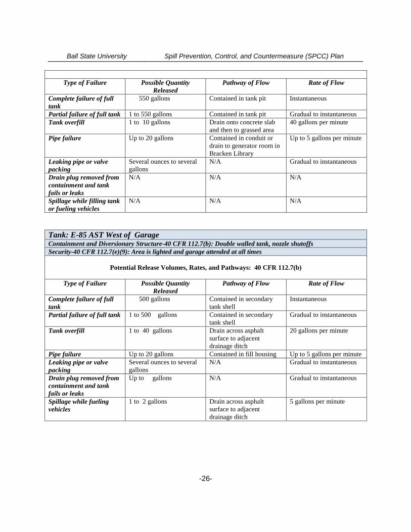
Type of Failure Possible QuantityReleased
Pathway of Flow Rate of Flow
Complete failure of fulltank
550 gallons Contained in tank pit Instantaneous
Partial failure of full tank 1 to 550 gallons Contained in tank pit Gradual to instantaneousTank overfill 1 to 10 gallons Drain onto concrete slab
and then to grassed area40 gallons per minute
Pipe failure Up to 20 gallons Contained in conduit ordrain to generator room inBracken Library
Up to 5 gallons per minute
Leaking pipe or valvepacking
Several ounces to severalgallons
N/A Gradual to instantaneous
Drain plug removed fromcontainment and tankfails or leaks
N/A N/A N/A
Spillage while filling tankor fueling vehicles
N/A N/A N/A
Tank: E-85 AST West of GarageContainment and Diversionary Structure-40 CFR 112.7(b): Double walled tank, nozzle shutoffsSecurity-40 CFR 112.7(e)(9): Area is lighted and garage attended at all times
Potential Release Volumes, Rates, and Pathways: 40 CFR 112.7(b)
Type of Failure Possible QuantityReleased
Pathway of Flow Rate of Flow
Complete failure of fulltank
500 gallons Contained in secondarytank shell
Instantaneous
Partial failure of full tank 1 to 500 gallons Contained in secondarytank shell
Gradual to instantaneous
Tank overfill 1 to 40 gallons Drain across asphaltsurface to adjacentdrainage ditch
20 gallons per minute
Pipe failure Up to 20 gallons Contained in fill housing Up to 5 gallons per minuteLeaking pipe or valvepacking
Several ounces to severalgallons
N/A Gradual to instantaneous
Drain plug removed fromcontainment and tankfails or leaks
Up to gallons N/A Gradual to instantaneous
Spillage while fuelingvehicles
1 to 2 gallons Drain across asphaltsurface to adjacentdrainage ditch
5 gallons per minute
Ball State University Spill Prevention, Control, and Countermeasure (SPCC) Plan
-27-
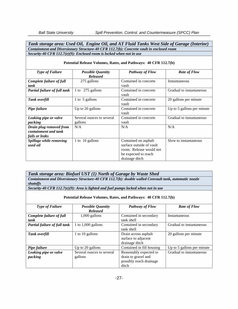
Tank storage area: Used Oil, Engine Oil, and AT Fluid Tanks West Side of Garage (Interior)Containment and Diversionary Structure-40 CFR 112.7(b): Concrete vault in enclosed roomSecurity-40 CFR 112.7(e)(9): Enclosed room is locked when not in use
Potential Release Volumes, Rates, and Pathways: 40 CFR 112.7(b)
Type of Failure Possible QuantityReleased
Pathway of Flow Rate of Flow
Complete failure of fulltank
275 gallons Contained in concretevault
Instantaneous
Partial failure of full tank 1 to 275 gallons Contained in concretevault
Gradual to instantaneous
Tank overfill 1 to 5 gallons Contained in concretevault
20 gallons per minute
Pipe failure Up to 20 gallons Contained in concretevault
Up to 5 gallons per minute
Leaking pipe or valvepacking
Several ounces to severalgallons
Contained in concretevault
Gradual to instantaneous
Drain plug removed fromcontainment and tankfails or leaks
N/A N/A N/A
Spillage while removingused oil
1 to 10 gallons Contained on asphaltsurface outside of vaultroom. Release would notbe expected to reachdrainage ditch
Slow to instantaneous
Tank storage area: Biofuel UST (1) North of Garage by Waste ShedContainment and Diversionary Structure-40 CFR 112.7(b): double walled Convault tank, automatic nozzleshutoffsSecurity-40 CFR 112.7(e)(9): Area is lighted and fuel pumps locked when not in use
Potential Release Volumes, Rates, and Pathways: 40 CFR 112.7(b)
Type of Failure Possible QuantityReleased
Pathway of Flow Rate of Flow
Complete failure of fulltank
1,000 gallons Contained in secondarytank shell
Instantaneous
Partial failure of full tank 1 to 1,000 gallons Contained in secondarytank shell
Gradual to instantaneous
Tank overfill 1 to 10 gallons Drain across asphaltsurface to adjacentdrainage ditch
20 gallons per minute
Pipe failure Up to 20 gallons Contained in fill housing Up to 5 gallons per minuteLeaking pipe or valvepacking
Several ounces to severalgallons
Reasonably expected todrain to gravel andpossibly reach drainageditch
Gradual to instantaneous
Ball State University Spill Prevention, Control, and Countermeasure (SPCC) Plan
-28-
Drain plug removed fromcontainment and tankfails or leaks
N/A N/A N/A
Spillage while filling tankor fueling vehicles
1 to 2 gallons Release could reasonablybe expected to reach opendrainage ditch to the west
5 gallons per minute
Tank storage area: Biofuel UST (2) North of Garage by Waste ShedContainment and Diversionary Structure-40 CFR 112.7(b): Double walled steel tank, automatic nozzle shutoffsSecurity-40 CFR 112.7(e)(9): Area is lighted and fuel pumps locked when not in use
Potential Release Volumes, Rates, and Pathways: 40 CFR 112.7(b)
Type of Failure Possible QuantityReleased
Pathway of Flow Rate of Flow
Complete failure of fulltank
1,000 gallons Contained in secondarytank shell
Instantaneous
Partial failure of full tank 1 to 1,000 gallons Contained in secondarytank shell
Gradual to instantaneous
Tank overfill 1 to 10 gallons Drain across asphaltsurface to adjacentdrainage ditch
20 gallons per minute
Pipe failure Up to 5 gallons Contained in fill housing Up to 5 gallons per minuteLeaking pipe or valvepacking
Several ounces to severalgallons
Reasonably expected todrain to gravel andpossibly reach drainageditch
Gradual to instantaneous
Drain plug removed fromcontainment and tankfails or leaks
N/A N/A N/A
Spillage while filling tankor fueling vehicles
1 to 2 gallons Release could reasonablybe expected to reach opendrainage ditch to the west
5 gallons per minute
Tank storage: Gasoline/Diesel UST (dual 500 gal tank) - North Grounds – 1,000 galloncapacity totalContainment and Diversionary Structure-40 CFR 112.7(b): Double walled ConVault tank, automatic nozzleshutoffsSecurity-40 CFR 112.7(e)(9): Area is lighted and area fenced and locked when not in use
Potential Release Volumes, Rates, and Pathways: 40 CFR 112.7(b)
Type of Failure Possible QuantityReleased
Pathway of Flow Rate of Flow
Complete failure of fulltank
500 gallons Contained in secondarytank shell
Instantaneous
Partial failure of full tank 1 to 500 gallons Contained in secondarytank shell
Gradual to instantaneous

Ball State University Spill Prevention, Control, and Countermeasure (SPCC) Plan
-29-
Tank overfill 1 to 5 gallons Reasonably expected todrain to gravel/soilsurface, impound, and notreach sewer or waterway
20 gallons per minute
Pipe failure Several ounces to gallons Reasonably expected todrain to gravel/soilsurface, impound, and notreach sewer or waterway
Gradual to instantaneous
Leaking pipe or valvepacking
Several ounces to gallons Reasonably expected todrain to gravel/soilsurface, impound, and notreach sewer or waterway
Gradual to instantaneous
Drain plug removed fromcontainment and tankfails or leaks
N/A N/A N/A
Spillage while filling tankor fueling vehicles
1 to 2 gallons Reasonably expected todrain to gravel/soilsurface, impound, and notreach sewer or waterway
5 gallons per minute
Tank storage area: Gasoline/Diesel AST (Dual 500 gal tank) - South Grounds – 1,000 galloncapacity totalContainment and Diversionary Structure-40 CFR 112.7(b): Double walled ConVault tank, automatic nozzleshutoffsSecurity-40 CFR 112.7(e)(9): Area is lighted and fuel pumps disabled when not in use
Potential Release Volumes, Rates, and Pathways: 40 CFR 112.7(b)
Type of Failure Possible QuantityReleased
Pathway of Flow Rate of Flow
Complete failure of fulltank
1,000 gallons Contained in secondarytank shell
Instantaneous
Partial failure of full tank 1 to 1,000 gallons Contained in secondarytank shell
Gradual to instantaneous
Tank overfill 1 to 5 gallons Reasonably expected todrain to asphalt surfacereach nearby storm sewerinlet
20 gallons per minute
Pipe failure Several ounces to gallons Reasonably expected todrain to gravel/soilsurface, impound, and notreach sewer or waterway
Gradual to instantaneous
Leaking pipe or valvepacking
Several ounces to severalgallons
Reasonably expected todrain to asphalt surfaceand reach storm waterdrain
Gradual to instantaneous
Drain plug removed fromcontainment and tankfails or leaks
N/A N/A N/A
Spillage while filling tank 1 to 2 gallons Reasonably expected to 5 gallons per minute
Ball State University Spill Prevention, Control, and Countermeasure (SPCC) Plan
-30-
or fueling vehicles drain to asphalt surfaceand reach storm waterdrain
Tank Storage: Diesel AST – Heath Farm – 300 gallon Biodiesel tankContainment and Diversionary Structure-40 CFR 112.7(b): Double walled steel tank, automatic nozzle shutoffsSecurity-40 CFR 112.7(e)(9): Area is lighted, nozzle is locked, and security fence is locked when not in use
Potential Release Volumes, Rates, and Pathways: 40 CFR 112.7(b)
Type of Failure Possible QuantityReleased
Pathway of Flow Rate of Flow
Complete failure of fulltank
300 gallons Contained in secondarytank shell
Instantaneous
Partial failure of full tank 1 to 300 gallons Contained in secondarytank shell
Gradual to instantaneous
Tank overfill 1 to 5 gallons Reasonably expected todrain to gravel surface andnot reach drain orwaterway
20 gallons per minute
Pipe failure N/A N/A N/ALeaking pipe or valvepacking
Several ounces to severalgallons
Reasonably expected todrain to gravel surface andnot reach drain orwaterway
Gradual to instantaneous
Drain plug removed fromcontainment and tankfails or leaks
Up to 300 gallons Reasonably expected todrain to gravel surface andpossibly reach yard drainto a waterway
Gradual to instantaneous
Spillage while filling tankor fueling vehicles
1 to 2 gallons Reasonably expected todrain to gravel surface andnot reach drain orwaterway
5 gallons per minute
Tank Storage: Diesel AST – SV Garage – 275 gallon engine oil tankContainment and Diversionary Structure-40 CFR 112.7(b): Double walled steel tank, automatic line feedSecurity-40 CFR 112.7(e)(9): Area is interior; locked if not occupied
Potential Release Volumes, Rates, and Pathways: 40 CFR 112.7(b)
Type of Failure Possible QuantityReleased
Pathway of Flow Rate of Flow
Complete failure of fulltank
275 gallons Contained in secondarytank shell
Instantaneous
Partial failure of full tank 1 to 300 gallons Contained in secondarytank shell
Gradual to instantaneous
Tank overfill 1-2 gallons Reasonably expected todrain to interior concreteslab and not reach floor
10 gallons per minute
Ball State University Spill Prevention, Control, and Countermeasure (SPCC) Plan
-31-
drainPipe failure N/A N/A N/ALeaking pipe or valvepacking
Several ounces to severalgallons
Reasonably expected todrain to interior concreteslab and not reach floordrain
Gradual to instantaneous
Drain plug removed fromcontainment and tankfails or leaks
N/A N/A N/A
Spillage while lubricatingvehicles through overheadsupply lines
1 gallon Reasonably expected todrain to interior concreteslab or service pits and notreach floor drain
2 gallons per minute
Container Storage Area: North Waste Accumulation Area - Shed ExteriorContainment and Diversionary Structure-40 CFR 112.7(b): NoneSecurity-40 CFR 112.7(e)(9): Area is lighted and under video surveillance
Potential Release Volumes, Rates, and Pathways: 40 CFR 112.7(b)
Type of Failure Possible QuantityReleased
Pathway of Flow Rate of Flow
Complete failure of fullcontainer
55 gallons Reasonably expected todrain to gravel surface andreach drainage way to thewest. Most will beretained on the gravelsurfaces with somereaching the surface ditchto the west.
Instantaneous
Partial failure of fullcontainer
1 to 55 gallons Reasonably expected todrain to and be retained onthe gravel surfaces.
Gradual to instantaneous
Overfill 1 gallon Reasonably expected todrain to and be retained onthe gravel surface in thearea
Instantaneous
Pipe failure N/A N/A N/ALeaking container Several ounces to 55
gallonsReasonably expected todrain to and be retained onthe gravel surface in thearea.
Gradual to instantaneous
Drain plug removed fromcontainment and tankfails or leaks
N/A N/A N/A
Spillage while removingwastes
1 to 55 gallons Reasonably expected todrain to gravel surface andpossibly reach waterway
Gradual to instantaneous
Ball State University Spill Prevention, Control, and Countermeasure (SPCC) Plan
-32-
Container Storage Area: North Waste Accumulation Area - Shed Interior – 1100 galloncapacityContainment and Diversionary Structure-40 CFR 112.7(b): NoneSecurity-40 CFR 112.7(e)(9): Area is lighted, under video surveillance, and access doors kept locked
Potential Release Volumes, Rates, and Pathways: 40 CFR 112.7(b)
Type of Failure Possible QuantityReleased
Pathway of Flow Rate of Flow
Complete failure of fullcontainer
55 gallons (5 drums) Retained in containmentsump (inside)
Instantaneous
Partial failure of fullcontainer
1 to 55 gallons Retained in containmentsump (inside)
Gradual to instantaneous
Overfill 1 gallon Retained in containmentsump (inside)
5 gallons per minute
Pipe failure N/A N/A N/ALeaking container Several ounces to 55
gallonsRetained in containmentsump (inside)
Gradual to instantaneous
Drain plug removed fromcontainment and tankfails or leaks
N/A N/A N/A
Spillage while removingwastes
1 to 55 gallons Reasonably expected todrain to gravel surface andimpound around shedperimeter
Gradual to instantaneous
Container Storage Area: Campus Waste Accumulation Area - CP 94 Waste AccumulationRoomContainment and Diversionary Structure-40 CFR 112.7(b): Concrete vault (floor with curbing)- 225 Galloncapacity in safety cabinets and on cartsSecurity-40 CFR 112.7(e)(9): Room is maintained locked and access is only through building interior
Potential Release Volumes, Rates, and Pathways: 40 CFR 112.7(b)
Type of Failure Possible QuantityReleased
Pathway of Flow Rate of Flow
Complete failure of fullcontainer
55 gallons Retained in concrete vault(inside)
Instantaneous
Partial failure of fullcontainer
1 oz. to 55 gallons Retained in containmentvault (inside)
Gradual to instantaneous
Overfill 1 oz. to 1 gallon Retained in containmentvault (inside)
Instantaneous
Pipe failure N/A N/A N/ALeaking container Several ounces to 55
gallonsRetained in containmentvault (inside)
Gradual to instantaneous
Drain plug removed fromcontainment and tankfails or leaks
N/A N/A N/A
Spillage while removing 1 to 55 gallons Retained in concrete vault Instantaneous
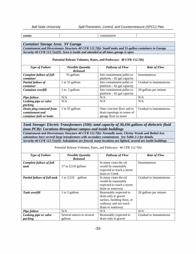
Ball State University Spill Prevention, Control, and Countermeasure (SPCC) Plan
-33-
wastes containment
Container Storage Area: SV GarageContainment and Diversionary Structure-40 CFR 112.7(b): Small tanks and 55-gallon containers in GarageSecurity-40 CFR 112.7(e)(9): Area is inside and attended at all times garage is open
Potential Release Volumes, Rates, and Pathways: 40 CFR 112.7(b)
Type of Failure Possible QuantityReleased
Pathway of Flow Rate of Flow
Complete failure of fullcontainer
55 gallons Into containment pallet orplatform – 62 gal capacity
Instantaneous
Partial failure ofcontainer
1 to 55 gallons Into containment pallet orplatform – 62 gal capacity
Gradual to instantaneous
Container overfill 1 to 2 gallons Into containment pallet orplatform – 62 gal capacity
20 gallons per minute
Pipe failure N/A N/A N/ALeaking pipe or valvepacking
N/A N/A N/A
Drain plug removed fromcontainment andcontainer fails or leaks
1 to 55 gallons Onto concrete floor and todrain openings in center ofgarage floor to sewer
Gradual to instantaneous
Tank Storage: Electric Transformers (100): total capacity of 30,436 gallons of dielectric fluid(non-PCB): Locations throughout campus and inside buildingsContainment and Diversionary Structure-40 CFR 112.7(b): Normally none. Christy Woods and Bethel Ave.substations have several large transformers with secondary containment. See Table 2-2 for details.Security-40 CFR 112.7(e)(9): Substations are fenced, many locations are lighted, several are inside buildings
Potential Release Volumes, Rates, and Pathways: 40 CFR 112.7(b)
Type of Failure Possible QuantityReleased
Pathway of Flow Rate of Flow
Complete failure of fulltank 17 to 3,510 gallons
In many cases the oilwould be reasonablyexpected to reach a stormdrain or Creek
Instantaneous
Partial failure of full tank 1 to 3,510 gallons In many cases the oilwould be reasonablyexpected to reach a stormdrain or waterway
Gradual to instantaneous
Tank overfill 1 to 5 gallons Reasonably expected todrain only to gravelsurface, building floor, orwalkway and not reachdrain or waterway
20 gallons per minute
Pipe failure N/A N/A N/ALeaking pipe or valvepacking
Several ounces to severalgallons
Reasonably expected todrain only to gravel
Gradual to instantaneous
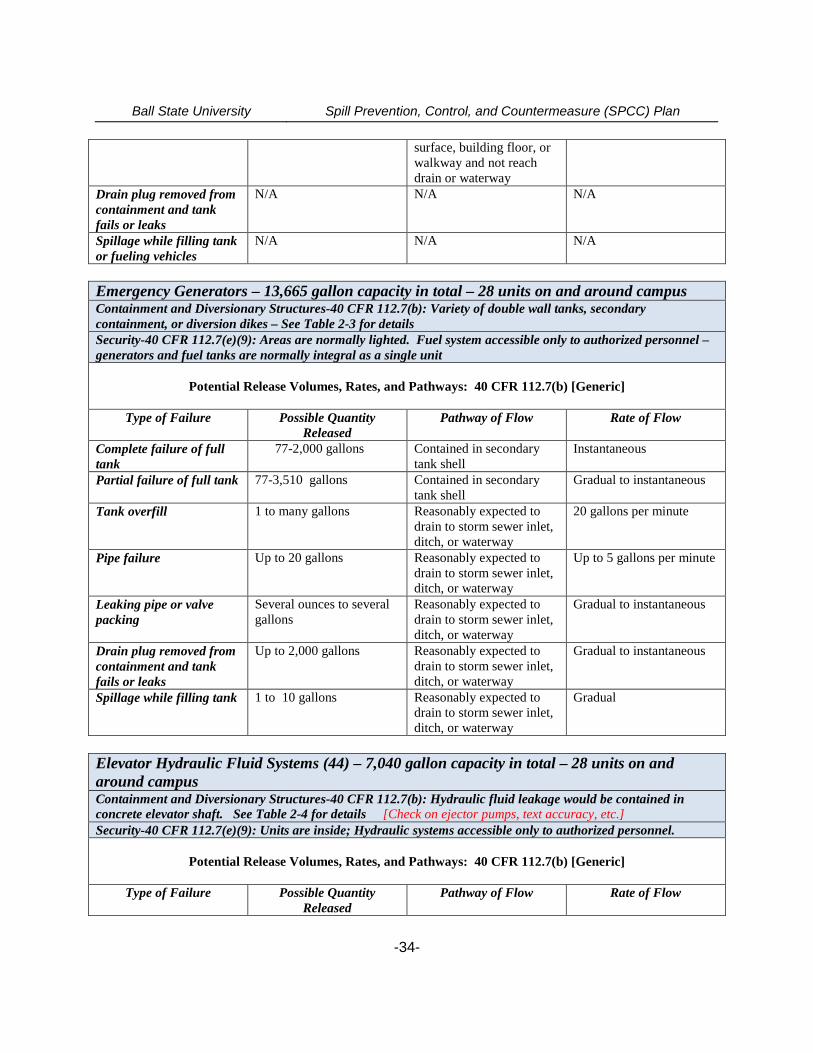
Ball State University Spill Prevention, Control, and Countermeasure (SPCC) Plan
-34-
surface, building floor, orwalkway and not reachdrain or waterway
Drain plug removed fromcontainment and tankfails or leaks
N/A N/A N/A
Spillage while filling tankor fueling vehicles
N/A N/A N/A
Emergency Generators – 13,665 gallon capacity in total – 28 units on and around campusContainment and Diversionary Structures-40 CFR 112.7(b): Variety of double wall tanks, secondarycontainment, or diversion dikes – See Table 2-3 for detailsSecurity-40 CFR 112.7(e)(9): Areas are normally lighted. Fuel system accessible only to authorized personnel –generators and fuel tanks are normally integral as a single unit
Potential Release Volumes, Rates, and Pathways: 40 CFR 112.7(b) [Generic]
Type of Failure Possible QuantityReleased
Pathway of Flow Rate of Flow
Complete failure of fulltank
77-2,000 gallons Contained in secondarytank shell
Instantaneous
Partial failure of full tank 77-3,510 gallons Contained in secondarytank shell
Gradual to instantaneous
Tank overfill 1 to many gallons Reasonably expected todrain to storm sewer inlet,ditch, or waterway
20 gallons per minute
Pipe failure Up to 20 gallons Reasonably expected todrain to storm sewer inlet,ditch, or waterway
Up to 5 gallons per minute
Leaking pipe or valvepacking
Several ounces to severalgallons
Reasonably expected todrain to storm sewer inlet,ditch, or waterway
Gradual to instantaneous
Drain plug removed fromcontainment and tankfails or leaks
Up to 2,000 gallons Reasonably expected todrain to storm sewer inlet,ditch, or waterway
Gradual to instantaneous
Spillage while filling tank 1 to 10 gallons Reasonably expected todrain to storm sewer inlet,ditch, or waterway
Gradual
Elevator Hydraulic Fluid Systems (44) – 7,040 gallon capacity in total – 28 units on andaround campusContainment and Diversionary Structures-40 CFR 112.7(b): Hydraulic fluid leakage would be contained inconcrete elevator shaft. See Table 2-4 for details [Check on ejector pumps, text accuracy, etc.]Security-40 CFR 112.7(e)(9): Units are inside; Hydraulic systems accessible only to authorized personnel.
Potential Release Volumes, Rates, and Pathways: 40 CFR 112.7(b) [Generic]
Type of Failure Possible QuantityReleased
Pathway of Flow Rate of Flow
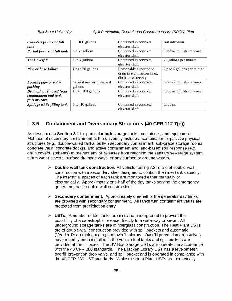
Ball State University Spill Prevention, Control, and Countermeasure (SPCC) Plan
-35-
Complete failure of fulltank
160 gallons Contained in concreteelevator shaft
Instantaneous
Partial failure of full tank 1-160 gallons Contained in concreteelevator shaft
Gradual to instantaneous
Tank overfill 1 to 4 gallons Contained in concreteelevator shaft
20 gallons per minute
Pipe or hose failure Up to 20 gallons Reasonably expected todrain to storm sewer inlet,ditch, or waterway
Up to 5 gallons per minute
Leaking pipe or valvepacking
Several ounces to severalgallons
Contained in concreteelevator shaft
Gradual to instantaneous
Drain plug removed fromcontainment and tankfails or leaks
Up to 160 gallons Contained in concreteelevator shaft
Gradual to instantaneous
Spillage while filling tank 1 to 10 gallons Contained in concreteelevator shaft
Gradual
3.5 Containment and Diversionary Structures (40 CFR 112.7(c))
As described in Section 3.1 for particular bulk storage tanks, containers, and equipment:Methods of secondary containment at the university include a combination of passive physicalstructures (e.g., double-walled tanks, built-in secondary containment, sub-grade storage rooms,concrete vault, concrete docks), and active containment and land-based spill response (e.g.,drain covers, sorbents) to prevent any oil releases from reaching the sanitary sewerage system,storm water sewers, surface drainage ways, or any surface or ground waters.
Double-wall tank construction. All vehicle fueling ASTs are of double-wallconstruction with a secondary shell designed to contain the inner tank capacity.The interstitial spaces of each tank are monitored either manually orelectronically. Approximately one-half of the day tanks serving the emergencygenerators have double wall construction;
Secondary containment. Approximately one-half of the generator day tanksare provided with secondary containment. All tanks with containment vaults areprotected from precipitation entry;
USTs. A number of fuel tanks are installed underground to prevent thepossibility of a catastrophic release directly to a waterway or sewer. Allunderground storage tanks are of fiberglass construction. The Heat Plant USTsare of double-wall construction provided with spill buckets and automatic(Veeder-Root) tank gauging and overfill alarms. Overfill prevention drop valveshave recently been installed in the vehicle fuel tanks and spill buckets areprovided at the fill pipes. The SV Bus Garage USTs are operated in accordancewith the 40 CFR 280 standards. The Bracken Library UST has a levelometer,overfill prevention drop valve, and spill bucket and is operated in compliance withthe 40 CFR 280 UST standards. While the Heat Plant USTs are not actually
Ball State University Spill Prevention, Control, and Countermeasure (SPCC) Plan
-36-
subject to the 40 CFR 280 UST standards, the construction, installation,protective features, inspection, and operation of these tanks are all designed tosatisfy those standards;
Active Containment Devices and Equipment. Spill cleanup kits that includeabsorbent material, booms, and other portable barriers are located at severallocations, as shown on a Facility Diagram in Appendix A. The spill kits arelocated within close proximity of the oil product storage, dispensing, and handlingareas for rapid deployment should a spill occur. Sorbent material, booms, draincovers, and other portable barriers are staged for quick deployment in the eventof a discharge during oil transfer activities or any other accidental discharges.The response equipment inventory for the facility is listed in Appendix J of thisPlan. The inventory is checked monthly to ensure that used material isreplenished. The BSU Spill Response Plan relates the response capabilities andprocedures for spills or releases of oil and other substances on the BSU campus;
Drainage system. Cardinal Creek comprises the main surface drainagewaterway serving the Ball State University campus. All separate storm drainsare directed to the either the ponds and creek, or interceptors or box culverts thatdrain to the ponds or creek. Drain covers are available for any interior drains,yard drains or curb inlets to the storm sewers that may be in the vicinity of oilstorage and handling operations. Oil absorbent booms are available to retainand recover any oil spillage to the surface waterways or ponds on the campus inorder to prevent its migration to York Prairie Creek, the receiving waterway; and,
Transformer containment. The individual pad-mounted transformers arenormally installed on elevated concrete slabs that do not afford containment forany dielectric oil spillage. Releases will be contained by deploying sorbentmaterial and other portable spill barriers upon discovery of the spill. Any stormsewer catch basins or drains near the transformers or electric substations will becovered in the event of a transformer spill or explosion in order to preventreleased oils accessing the storm drainage system. The transformers installed intransformer banks or electrical substations are normally afforded secondarycontainment by a gravel bed that surrounds the concrete slabs on which thetransformers are mounted.
3.6 Practicability of Secondary Containment (40 CFR 112.7(d))
Ball State University Facilities Management has determined that the use of oil storage vesselswith integral secondary containment, active and passive secondary containment devices andprotocols, preparedness and response training and inspection procedures, along with readilyavailable equipment to prevent discharge of oil from reaching navigable waters, is practical andeffective at this facility.
Ball State University Spill Prevention, Control, and Countermeasure (SPCC) Plan
-37-
All above-ground bulk storage containers are provided with secondary containment (double-walls, vaults, or dikes) with the exception of the following:
The 175 gallon diesel fuel storage tank serving the Noyer Phone emergency generatorat Noyer complex;
The used oil (55-gallon drum) and waste container storage area adjacent to the wasteshed north of the Service and Stores building; and,
It is our intention to provide passive secondary containment (double-walled tank, vaults, berms,containment pallets, or dikes) for the above vessels as soon as practicable. In the meantime,adequate spill response equipment (absorbents, drain seals, booms, etc.) and training areprovided to ensure that our active containment measures will be protective and serve assecondary containment.
Those oil storage vessels or oil handling activities that are not provided with passive secondarycontainment are afforded active secondary containment through the provision of adequatesorbent materials and other response equipment.
3.7 Inspections, Tests, and Records (40 CFR 112.7(e))
As required by the SPCC rule, Ball State University performs the inspections, tests, andevaluations listed in Table 3-2. The inspections and tests are described later in this section,and in the respective sections that describe different parts of the facility (e.g., Section 4.2.6 forbulk storage containers). The inspection forms to be utilized may be found in Appendix C.
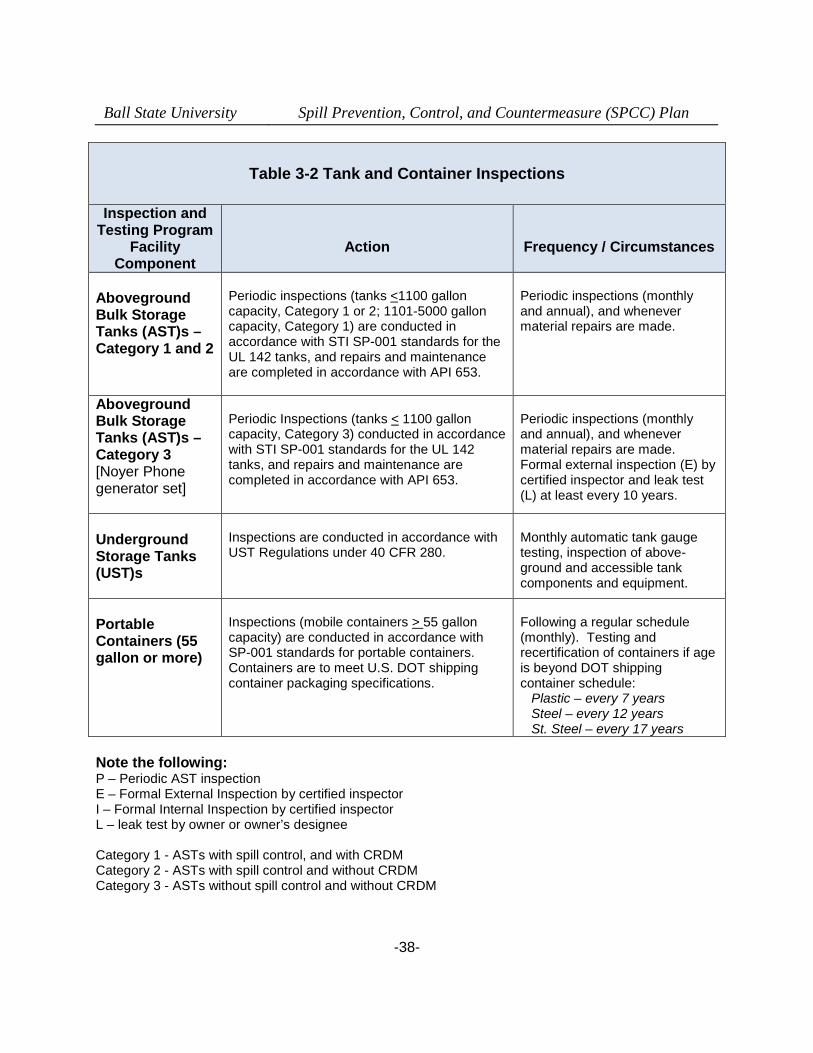
Ball State University Spill Prevention, Control, and Countermeasure (SPCC) Plan
-38-
Table 3-2 Tank and Container Inspections
Inspection andTesting Program
FacilityComponent
Action Frequency / Circumstances
AbovegroundBulk StorageTanks (AST)s –Category 1 and 2
Periodic inspections (tanks <1100 galloncapacity, Category 1 or 2; 1101-5000 galloncapacity, Category 1) are conducted inaccordance with STI SP-001 standards for theUL 142 tanks, and repairs and maintenanceare completed in accordance with API 653.
Periodic inspections (monthlyand annual), and whenevermaterial repairs are made.
AbovegroundBulk StorageTanks (AST)s –Category 3[Noyer Phonegenerator set]
Periodic Inspections (tanks < 1100 galloncapacity, Category 3) conducted in accordancewith STI SP-001 standards for the UL 142tanks, and repairs and maintenance arecompleted in accordance with API 653.
Periodic inspections (monthlyand annual), and whenevermaterial repairs are made.Formal external inspection (E) bycertified inspector and leak test(L) at least every 10 years.
UndergroundStorage Tanks(UST)s
Inspections are conducted in accordance withUST Regulations under 40 CFR 280.
Monthly automatic tank gaugetesting, inspection of above-ground and accessible tankcomponents and equipment.
PortableContainers (55gallon or more)
Inspections (mobile containers > 55 galloncapacity) are conducted in accordance withSP-001 standards for portable containers.Containers are to meet U.S. DOT shippingcontainer packaging specifications.
Following a regular schedule(monthly). Testing andrecertification of containers if ageis beyond DOT shippingcontainer schedule:
Plastic – every 7 yearsSteel – every 12 yearsSt. Steel – every 17 years
Note the following:P – Periodic AST inspectionE – Formal External Inspection by certified inspectorI – Formal Internal Inspection by certified inspectorL – leak test by owner or owner’s designee
Category 1 - ASTs with spill control, and with CRDMCategory 2 - ASTs with spill control and without CRDMCategory 3 - ASTs without spill control and without CRDM
Ball State University Spill Prevention, Control, and Countermeasure (SPCC) Plan
-39-
3.7.1 Weekly Inspection
A Ball State University employee (environmental specialist, supervisor, or a designatedemployee) normally performs a walk-through of, or visit to, major oil storage and handling areasat least weekly. This weekly visual survey involves: (1) looking for tank/piping or containerdamage or leakage, stained or discolored soils; (2) checking for signs of oil leakage fromcontainers and tanks and on floors or ground surface; and (3) verifying that the containmentmechanisms or capabilities remain adequate. While not formally recorded or reported unlessproblems are observed, all oil-handling personnel are trained to be alert to potential problems ordeficiencies during their work around the ASTs, USTs, and CSAs.
3.7.2 Monthly Inspection
The checklist provided in Appendix C is used for monthly inspections by Ball State Universitypersonnel. The monthly inspections are designed to incorporate all applicable elements underthe STI SP001 monthly inspection form, and cover the following key features:
Observing the exterior of the aboveground storage tanks, pipes, dispensers,hoses, and other equipment for signs of deterioration, leaks, corrosion, andthinning.
Observing the exterior of portable containers for signs of deterioration or leaks. Observing the tank foundations and supports for signs of instability or excessive
settlement. Observing the tank fill and discharge pipes for signs of poor connection that
could cause a discharge, and tank vent for obstructions and proper operation. Verifying the proper functioning of overfill prevention and interstitial space
monitoring systems. Checking the inventory of discharge response equipment and restocking as
needed.
All potential problems regarding tanks, piping, containment, or response equipment mustimmediately be reported to the BSU Environmental Specialist. Visible oil leaks from tank walls,piping, or other components must be repaired as soon as possible to prevent a larger spill or adischarge to the combined sewer. Pooled oil, contained liquids with an oil sheen, or stained soilis to be reported and removed immediately upon discovery.
Written monthly inspection records are signed by the Environmental Specialist, or the BSUdesignee, and maintained with this SPCC Plan for a period of three years.
3.7.3 Annual Inspection
Facility personnel perform a more thorough inspection of facility equipment on an annual basis.This annual inspection complements the monthly inspection described above using the checklistprovided in Appendix C of this Plan.
Ball State University Spill Prevention, Control, and Countermeasure (SPCC) Plan
-40-
The annual inspection is preferably performed after a large storm event in order to verify theimperviousness and/or functioning of drainage control systems and to verify the direction andfate of the site drainage that may serve to transport any oil spills or releases.
Written annual inspection records are signed by the Environmental Specialist, or his designee,and maintained with this SPCC Plan for a period of three years.
3.7.4 Periodic Integrity Testing
In addition to the above monthly and annual inspections by facility personnel, the ASTs may beperiodically evaluated by an outside certified tank inspector following the Steel Tank Institute(STI) Standard for the Inspection of Aboveground Storage Tanks, SP-001, or in accordance withAPI 653, as described here and in Section 4.2.6 of this Plan.
3.8 Personnel, Training, and Discharge Prevention Procedures(40 CFR 112.7(f))
BSU Facilities Planning and Management is the party responsible for oil discharge prevention,control, and response preparedness activities at this facility. The Environmental Specialist isresponsible for routine and day-to-day maintenance and operational activities to prevent therelease of oil or other chemicals.
Ball State University management has instructed oil-handling facility personnel in the operationand maintenance of oil pollution prevention equipment, discharge procedure protocols,applicable pollution control laws, rules and regulations, general facility operations, and thecontent of this SPCC Plan. Any new facility personnel with oil handling responsibilities areprovided with this same training prior to being involved in any unsupervised oil handlingoperations or activities.
Annual discharge prevention briefings are held by the Environmental Specialist, or his designee,for all facility supervisors and personnel involved in oil storage and handling operations. Thesebriefings may be performed through online or web based training classes. The briefings areaimed at ensuring continued understanding and adherence to the discharge preventionprocedures presented in the SPCC Plan. The briefings also highlight and describe knowndischarge events or failures, malfunctioning components, and recently implementedprecautionary measures and best management practices. Facility operators and otherpersonnel will have the opportunity during the briefings to share recommendations concerninghealth, safety, and environmental issues encountered during facility operations.
Records of the briefings and discharge prevention training are kept on the form shown inAppendix E, a similar form, or in an electronic format, and are maintained with this SPCC Planfor a period of at least three years.
Ball State University Spill Prevention, Control, and Countermeasure (SPCC) Plan
-41-
3.9 Security (40 CFR 112.7(g))
For the BSU Campus facility as a whole, security is the full-time responsibility of University Public SafetyDepartment (University Police). Public Safety maintains a round the clock vigil of the campus, usingsquad cars and walking patrolmen. The campus is well lit for illumination after dark. Area lighting islocated in such positions as to illuminate the storage tank, container, transformer, generator, and otheroil handling areas. Consideration and instruction was given to the University Police and maintenancesupervisors regarding awareness of spills and discouraging fuel theft or possible sabotage. TheUniversity Police are provided with access to this SPCC Plan and have a copy of the associated BSUSpill Response Plan.
3.10 Oil Transfer Procedures (40 CFR 112.7(h)(2) and (3))
The BSU facility does not maintain a loading/unloading rack - as defined or intended by EPAunder section 112.7(h) of the regulations. Regardless, the potential for discharges during tankertruck unloading operations is of concern at this facility. Ball State University management iscommitted to ensuring the safe transfer of material to and from all oil storage tanks.
All suppliers must meet the minimum requirements and regulations for tank truckloading/unloading established by the U.S. Department of Transportation. Ball State Universityensures that the vendor understands the site layout, knows the protocol for entering the facilityand unloading product, and has the necessary equipment to respond to a discharge from thevehicle or fuel delivery hose. Similar precautions are undertaken during the removal of usedoils from the facility.
The AST and UST filling operations are overseen by supplier personnel trained in properdischarge prevention procedures. Larger deliveries, to any tank with over a 1,000 galloncapacity, will be observed by a trained BSU employee. The delivery truck driver and universityrepresentative are to remain with the vehicle at all times while fuel is being transferred. Transferoperations are performed in accordance with the following minimum procedures and the morespecific protocols outlined in Table 3-3:
o All oil transfer operations occur above ground and in plain sight;
o All facility oil transfer operations occur during daylight hours, or under sufficientillumination to be capable of observing any spillage;
o For fuel transfers of significant quantities or at sensitive locations, at least one trained,BSU individual is present and observes the transfer of oil during the entire transferprocess;
o Where oil transfer is to occur near a storm drain drop inlet, the trained facility individualpresent during product transfer shall cover the storm drain drop inlet with a close-sealing, impermeable mat. Following successful transfer of the product or waste, themat seal shall be removed;

Ball State University Spill Prevention, Control, and Countermeasure (SPCC) Plan
-42-
o Where oil transfer is to occur near a surface drain or waterway, the trained facilityindividual present during product transfer shall ensure that adequate spill containment,diversion, or absorption equipment is readily available at the location to prevent anyspillage from reaching the drainage way;
o The driver and/or university representative are to immediately report any size release ofoil to a waterway or sewer, or a ground spill or spill to the tarmac, gravel surface, or soilto the University Police and the BSU EHS Office;
o Drivers are not to leave the location where the spillage occurred until approved fordeparture by the University Police or EHS Department;
o Any release of oil must be prevented from reaching a storm or sanitary sewer orwaterway and cleanup begun as soon as practicable;
o Any spillage must be contained as soon as it occurs and be reported to the BSU EHSOffice as soon as practicable. All oil spills, regardless of quantity involved, are to becleaned up – any releases not promptly addressed must be reported to the IDEM underthe Indiana Spill Rule.
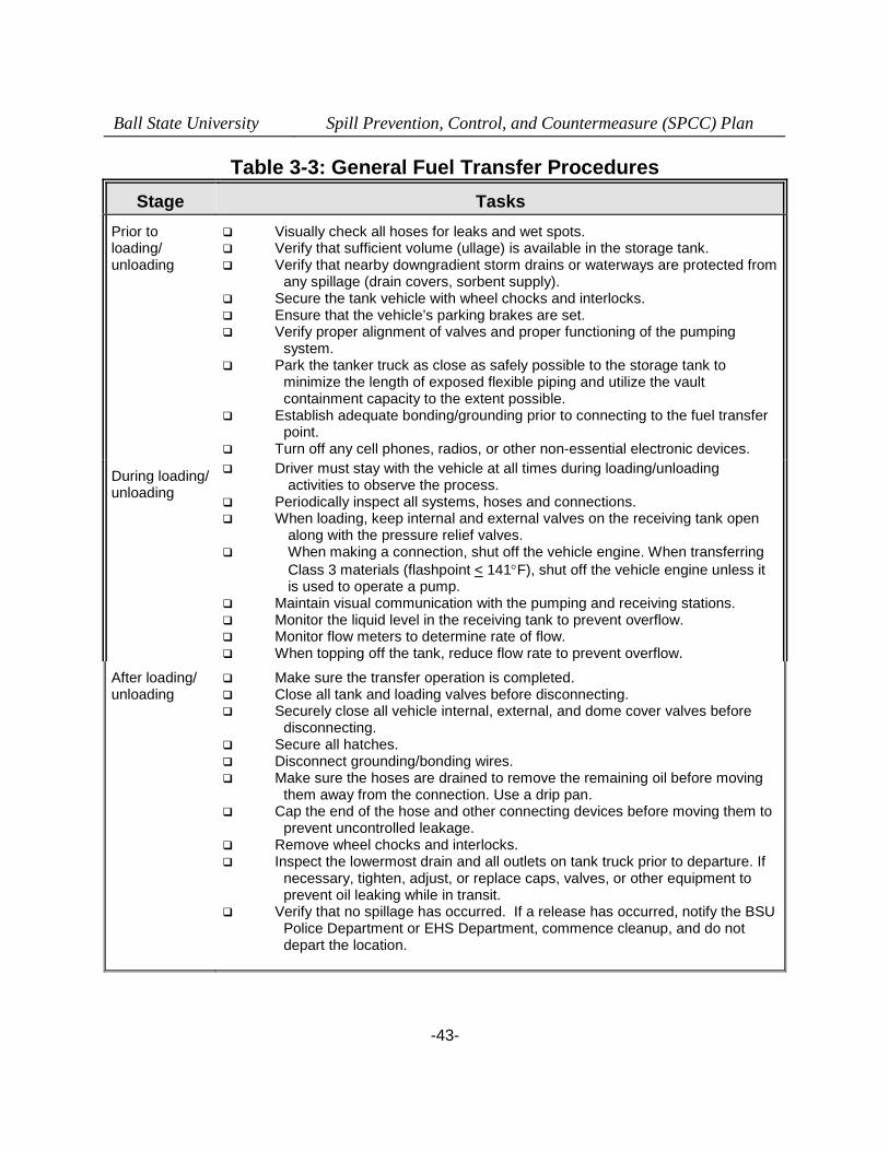
Ball State University Spill Prevention, Control, and Countermeasure (SPCC) Plan
-43-
Table 3-3: General Fuel Transfer Procedures
Stage Tasks
Prior toloading/unloading
Visually check all hoses for leaks and wet spots. Verify that sufficient volume (ullage) is available in the storage tank. Verify that nearby downgradient storm drains or waterways are protected from
any spillage (drain covers, sorbent supply). Secure the tank vehicle with wheel chocks and interlocks. Ensure that the vehicle’s parking brakes are set. Verify proper alignment of valves and proper functioning of the pumping
system. Park the tanker truck as close as safely possible to the storage tank to
minimize the length of exposed flexible piping and utilize the vaultcontainment capacity to the extent possible.
Establish adequate bonding/grounding prior to connecting to the fuel transferpoint.
Turn off any cell phones, radios, or other non-essential electronic devices.
During loading/unloading
Driver must stay with the vehicle at all times during loading/unloadingactivities to observe the process.
Periodically inspect all systems, hoses and connections. When loading, keep internal and external valves on the receiving tank open
along with the pressure relief valves. When making a connection, shut off the vehicle engine. When transferring
Class 3 materials (flashpoint < 141F), shut off the vehicle engine unless itis used to operate a pump.
Maintain visual communication with the pumping and receiving stations. Monitor the liquid level in the receiving tank to prevent overflow. Monitor flow meters to determine rate of flow. When topping off the tank, reduce flow rate to prevent overflow.
After loading/unloading
Make sure the transfer operation is completed. Close all tank and loading valves before disconnecting. Securely close all vehicle internal, external, and dome cover valves before
disconnecting. Secure all hatches. Disconnect grounding/bonding wires. Make sure the hoses are drained to remove the remaining oil before moving
them away from the connection. Use a drip pan. Cap the end of the hose and other connecting devices before moving them to
prevent uncontrolled leakage. Remove wheel chocks and interlocks. Inspect the lowermost drain and all outlets on tank truck prior to departure. If
necessary, tighten, adjust, or replace caps, valves, or other equipment toprevent oil leaking while in transit.
Verify that no spillage has occurred. If a release has occurred, notify the BSUPolice Department or EHS Department, commence cleanup, and do notdepart the location.
Ball State University Spill Prevention, Control, and Countermeasure (SPCC) Plan
-44-
3.11 Brittle Fracture Evaluation (40 CFR 112.7(i))
No field-constructed oil storage tanks are present at the university. All oil storage tanks wereshop-built.
3.12 Conformance with State and Local Applicable Requirements (40 CFR112.7(j))
All bulk storage tanks at this facility are registered with the state and local authorities, ifrequired, and have any necessary current certificates of registration and special use permitsrequired by the local fire code.
Ball State University Spill Prevention, Control, and Countermeasure (SPCC) Plan
-45-
PART 4: Discharge Prevention – SPCC Provisions forOnshore Facilities (Excluding Production Facilities)
4.1 Facility Drainage (40 CFR 112.8(b))
As noted previously in Section 2.2.1, all surface water drainage across the BSU campus isdirected either overland or through a network of catch basins, storm sewers, and box culverts toone of several surface water impoundments (ponds) and the interconnecting Cardinal Creek,which flows subsurface for part of its northwesterly route, to the York Prairie Creek. The northcampus area and the Heath Farm are both served by a series of subsurface and surfacedrainage ways that drain west/northwest to Eagle Branch and Jake’s Creek and then to KillbuckCreek before eventually joining with the White River near Anderson, Indiana. The BSU SPCCand Storm Water Quality Management Plan, as well as the BSU Spill Response Plan, aredesigned to prevent the release of oil to the waters of the State either overland or through thestorm drainage network.
4.2 Bulk Storage Containers (40 CFR 112.8(c))
Section 2.1.2 summarized the construction, volume, and content of the regulated bulk storagecontainers at BSU. Oil containing vessels that are integral to operational equipment (electrictransformers, elevator hydraulic systems) would not be considered “bulk storage” under theregulations at the Ball State University facility, but were also listed and described in Section 2and the associated Tables. That equipment or other oil handling operations are subject to onlythe general secondary containment requirements under the SPCC standards. The gasolineUSTs located at the Service and Stores garage, and the UST at Bracken Library are operated incompliance with federal UST regulations at 40 CFR 280 and are therefore not covered by theserequirements under 40 CFR 112.
Passive (Physical) Containment
Section 2 of this SPCC Plan identified the bulk fuel storage tanks that are subject to the specificsecondary containment provisions under this section of the SPCC requirements. With theexception of the small tank serving the phone generator at Noyer complex, and the CSA on thenorth grounds of the campus, all bulk storage tanks and containers of 55-gallon or greatercapacity are provided with secondary containment through one or more means includingdouble-walls, containment vaults, or spill containment pallets or platforms.
Active (Response) Containment
Each of the bulk storage tanks for fueling vehicles identified in Section 2 are also provisionedwith spill response equipment for deployment and use by trained BSU personnel. At least oneFuel Spill Response equipment container (55-gallon open head drum with label) is providedimmediately adjacent to each of the above-ground fuel tanks.
Ball State University, LLC Spill Prevention, Control, and Countermeasure (SPCC) Plan
-46-
Overpack containers (95-gallon drums) with additional quantities of absorbents are provided inthe BSU physical plant (Heat and Chill plants and the coal yard) that are available for any spillsat the USTs, from hydraulic systems, or other potential oil release sources in or around thephysical plant facilities.
The spill response supplies and equipment provided at the bulk storage tanks, as well as otherlocations, are itemized in Appendix J of this SPCC Plan.
4.2.1 Construction (40 CFR 112.8 (c)(1))
All above-ground bulk oil tanks used at this facility are shop-constructed of steel, in accordancewith industry specifications (UL-142). All oil storage portable containers are constructed of steelor plastic and meet U.S. DOT requirements for shipping containers. All steel tanks andcontainers are inspected in accordance with the Steel Tank Institute Standard (STI) SP001, 4th
edition, including containers as small as 55 gallons. The design and construction of all bulkstorage containers are compatible with the characteristics of the oil product they contain, andwith temperature and pressure conditions. The underground fuel oil and gasoline tanks are allof fiberglass construction in compliance with current design and installation standards under theeither the 40 CFR 280, or 40 CFR 112 requirements, or both.
4.2.2 Secondary Containment (40 CFR 112.8(c)(2))
This section of the SPCC regulations relates to only the “bulk oil storage” facilities at BSU andtherefore includes only the AST, UST, and container storage areas where “bulk storage” of oilsmay occur. The USTs storing fuel oil for the BSU Heat Plant are double-walled and offiberglass construction with automatic tank gauging for leak detection. All above ground vehiclefueling tanks have integral secondary containment in the form of a double-walled tank or asingle steel tank with integral secondary containment in the form of a concrete vault withinterstitial monitoring gauges. With the exception of the tank serving the Noyer phonegenerator, all other bulk containers are double-walled or provided with a containment vault.
With the exception of the north campus CSA adjacent to the waste shed, other portable and 55-gallon containers are in locations with concrete containment or prefabricated containmentpallets or platforms.
The tank systems and the areas surrounding the tank and container locations are visuallyinspected during the monthly facility inspections to detect any cracks, signs of heaving orsettlement, or other structural damage that could affect the ability of the tank to contain oil. Anydamage is promptly corrected to prevent migration of oil into the ground, or out of the tanks tothe ground surface.
4.2.3 Drainage of Diked Areas (40 CFR 112.8(c)(3))
The only “diked” bulk oil storage areas are the concrete or prefabricated vaults serving the usedoil storage tanks at the SV Bus Garage, the north campus waste shed, the Cooper ScienceBuilding waste accumulation room, and the genset locations that do not have double-walled
Ball State University, LLC Spill Prevention, Control, and Countermeasure (SPCC) Plan
-47-
tanks. As these units are located under roof or other protective enclosure there is no routineprecipitation that would require draining, and any liquid removal from the vault would requirepumping as no passive drain exists to serve the units. Regardless, any secondary containmentdrainage events will be recorded on the form included in Appendix D of this Plan. It is alsopossible that portable containers may be temporarily stored on prefabricated containmentpallets or platforms outside that may require drainage. Records are maintained at the facility forat least three years.
4.2.4 Corrosion Protection (40 CFR 112.8(c)(4))
All underground storage tanks on the premises are of fiberglass construction or coated steel,and the above-ground bulk fuel storage tanks are not in contact with the ground surface. Anyportable containers, if stored on the ground surface, are not at such locations for more than 90days which limits the progress of any potential corrosion.
4.2.5 Partially Buried and Bunkered Storage Tanks (40 CFR 112.8(c)(5))
This section is not applicable since there are no partially buried or bunkered storage tanks atthis facility.
4.2.6 Inspections and Tests (40 CFR 112.8(c)(6))
Facility personnel perform visual inspections of the ASTs according to the procedures describedin Section 3.1 of this SPCC Plan. Leaks from tank valves, dispensers, seams, gaskets, rivets,and bolts are promptly corrected. Records of inspections and tests are signed by the inspectorand kept at the facility for at least three years.
The scope and schedule of certified inspections and tests performed on the AST are specified inSTI Standard SP-001. The external inspection may include ultrasonic testing of the shell, ifspecified in the standard, or if recommended by the certified tank inspector to assess theintegrity of the tank for continued oil storage.
The underground fuel oil and gasoline tanks are all of fiberglass or coated steel constructionand are tested weekly and automatically by the Veeder-Root automatic tank gauging, overfill,and leak detection systems. The small UST serving the Bracken Library is inspected at leastmonthly, including the levelometer in the generator room and a monitoring well installed in thetank backfill zone.
Records of certified tank inspections will be kept at the facility for at least three years. Shell testcomparison records will be retained for the life of the tanks.
Table 3-2 summarizes inspections and tests performed on bulk storage containers as discussedin Section 3.1 of this Plan.
Ball State University, LLC Spill Prevention, Control, and Countermeasure (SPCC) Plan
-48-
4.2.7 Heating Coils (40 CFR 112.8(c)(7))
There are no internal heating coils installed in any of the oil tanks or containers and there are noexternal heat sources associated with any of the vessels.
4.2.8 Overfill Prevention Systems (40 CFR 112.8(c)(8))
Facility personnel are present throughout the filling operations of bulk storage tanks to monitorthe product level in the tanks and to ensure that no leakage occurs from flexible hoses or fixedpiping, couplings, or valves at the tank, or the delivery vehicle. All the bulk ASTs and USTs forvehicle fuel storage and dispensing, as well as the Heat Plant fuel oil tanks, are provided withcatchment basins or spill buckets. Additionally, the fuel dispensing USTs, and the BrackenLibrary UST, are provided with overfill prevention drop tubes in the fill pipes. The fuel USTs atthe Service and Stores building are also provided with visual and audible alarms to warn of animpending overfill. The other bulk storage tanks are of small capacity and visually gauged andobserved during the addition of fuel to prevent overfills.
4.2.9 Effluent Treatment Facilities (40 CFR 112.8(c)(9))
The campus is covered under a General NPDES Permit for storm water discharges as amunicipal separate sanitary sewer (MS4) entity. The university maintains and implements aStorm Water Quality Management Plan (SWMQP) to eliminate or control the release ofcontaminants to the waters of the state.
BSU has submitted permit applications to the City of Muncie Bureau of Water Quality (June of2011) for all food service establishments operating on the campus. These applications are forfats, oils, and grease (FOG) permit coverage under the City’s industrial wastewater permitprogram authority. Details of the grease interceptors serving several of the food serviceestablishments were provided in those applications.
4.2.10 Visible Discharges (40 CFR 112.8(c)(10))
Visible discharges from any tank, container, equipment, or appurtenances – including seams,gaskets, piping, pumps, valves, bungs, rivets, and bolts – are quickly corrected upon discovery,or the oil is transferred to another container.
Contained precipitation and any incidental oil spillage is promptly removed from the area of anytanks or containers and disposed of according to the waste disposal method described inSection 5 of this Plan. Similarly, any spillage or contents are routinely disposed if revealedduring inspections of the spill containment pallets or sumps provided in the container storageareas in order to maintain adequate secondary containment capacity for those units.

Ball State University, LLC Spill Prevention, Control, and Countermeasure (SPCC) Plan
-49-
4.2.11 Mobile and Portable Containers (40 CFR 112.8(c)(11))
Fuel delivery trucks serving Ball State University generally depart the facility immediately uponcompleting the fuel delivery and after ensuring that all valves are properly closed and cappedand the hoses secured. They do not remain at the facility while full (or empty) overnight or foran extended period of time.
Portable oil containers of 55-gallon capacity or greater must meet DOT requirements forshipping containers and be stored closed except when adding or removing oil.
4.3 Transfer Operations, Pumping, and In-Plant Processes(40 CFR 112.8(d))
Subsurface service piping is limited to the USTs containing oil on the campus and those areshort runs. The dispenser lines serving the SV Bus Garage tanks are the European Suctiontype.
Lines that are not in service or are on standby for an extended period of time are capped orblank-flanged and marked as to their origin.
All pipe supports are designed to minimize abrasion and corrosion and to allow for expansionand contraction. Pipe supports are visually inspected during the monthly inspection of thefacility.
Brightly painted bollards or barriers are placed where needed to prevent vehicular collisions withthe tanks or ancillary equipment.
Ball State University, LLC Spill Prevention, Control, and Countermeasure (SPCC) Plan
-50-
Part 5: Discharge Response
This section describes the response and cleanup procedures in the event of an oil discharge.The uncontrolled release of oil to groundwater, surface water, or soil, is prohibited by state andfederal laws or regulations. Immediate action must be taken to control, contain, and recover anyreleased or spilled petroleum product or used oil. The BSU Spill Response Plan provides moredetailed response procedures for both oils and other materials that may be released.
In general, the following steps are taken:
Eliminate potential spark sources; If possible and safe to do so, identify and shut down the source of the release or
discharge to stop the flow; Contain the discharge with sorbents, berms, trenches, sandbags, or other
material; Obstruct the discharge from accessing surface waterways or storm or sanitary
sewers by covering catch basins or curb drains, trenching, or creating diversionditches with sorbents or soil;
Notify University Police to contact the Facility Response Coordinator, his/heralternate, or the BSU Environmental Specialist;
Contact regulatory authorities and the appropriate response organization (ifrequired or necessary – See Appendices H and I); and
Collect and dispose of recovered product and contaminated debris according toapplicable regulations.
Restock any spill control equipment expended; Make any necessary follow-up reports, and evaluate the incident and response to
determine if any changes or improvements are needed to personnel training,response procedures, or equipment
For the purpose of establishing appropriate response procedures, this SPCC Plan classifiesdischarges as either “minor” or “major,” depending on the volume and characteristics of thematerial released.
A list of Emergency Contacts is provided in Appendix H and who must be contacted isestablished in Appendix I--depending on the quantity and circumstances of the oil spill. The listis also posted at prominent locations throughout the facility. A list of spill response materialskept at the facility is included in Appendix J and their location is shown on Figure A-2 to thisPlan.
5.1 Response to a Minor Discharge
A “minor” discharge is defined as one that poses no significant harm (or threat) to human healthand safety or to the environment. Minor discharges are generally those where the release is
Ball State University Spill Prevention, Control, and Countermeasure (SPCC) Plan
-51-
contained within or adjacent to the secondary containment device or structure and the quantitiesare relatively small. Characteristics of a minor discharge include the following:
The quantity of product discharged outside of the secondary containment is small(e.g., less than 55 gallons of oil released; and oil does not reach or threaten toreach a waterway, drain, or sewer inlet);
Spilled material is easily stopped, contained, and controlled at the time of thedischarge;
The spill is localized near the source; Discharged material is not likely to reach water (or sewer drains), or migrate off
university property in a quantity exceeding 55 gallons; There is little risk to human health or safety; and There is little risk of fire or explosion.
Minor discharges can usually be cleaned up by Ball State University personnel, and normallyreporting to the IDEM, City authorities, or the EPA is not required or necessary. The followingguidelines apply:
Immediately notify your supervisor, the Facility Response Coordinator orEnvironmental Specialist through Work Control at 5-5081, or after 4 PM, or if indoubt as to the severity of the release--contact the University Police at 5-1111 or911. The University Police serve as the central notification point for these, andother emergencies and they will notify the necessary parties;
Determine whether available response personnel have received training underthe University Hazard Communication program, and this SPCC Plan, for theresponse;
Don any necessary personal protective equipment and retrieve the necessaryspill control materials or devices;
Under the direction of the supervisor, Facility Response Coordinator, orEnvironmental Specialist, locate and stop the source of the release;
Contain the discharge with the appropriate discharge response materials andequipment;
Place discharge debris in properly labeled waste containers. The materialdisposal arrangements will be made by the BSU Environmental Specialist anddetermine the needs for post-cleanup environmental assessment of the location;
The Environmental Specialist, or his designee, will complete the dischargenotification form (Appendix I), or an incident report, and attach a copy to thisSPCC Plan or place it in an associated office file.
5.2 Response to a Major Discharge
A “major” discharge is defined as one that cannot be safely controlled or cleaned up by facilitypersonnel, or when reporting to regulatory agencies is required, such as when:
The release quantity is large enough to spread beyond the immediate dischargearea and cannot be rapidly or safely controlled;
Ball State University Spill Prevention, Control, and Countermeasure (SPCC) Plan
-52-
The quantity discharged exceeds 55 gallons and may discharge or flow beyondthe BSU property boundary;
The quantity released exceeds 1,000 gallons total, even though it remains on theBSU property;
The discharged material enters or will enter a surface waterway, drain, or sewer; The discharge requires special equipment or training to clean up; The discharged material poses a hazard to human health or safety; or There has been or is a danger of fire or explosion.
In the event of a major discharge, the following guidelines apply:
All persons, other than response personnel, must immediately vacate thedischarge location via the established exit routes and move to designated stagingareas at a safe distance from the discharge. Emergency notification andresponse procedures for students and employees are part of the BSU CrisisManagement Plan;
The supervisor, senior staff or faculty, or any other party, should contact theUniversity Police (5-1111 or 911) and Work Control (5-5081) for notification of theappropriate response parties;
The Facility Response Coordinator, a designee, or the Environmental Specialisthas authority to initiate notification and response. Certain notifications aredependent on the circumstances and type of discharge. For example, if oilreaches a sanitary sewer or combined sewer, the publicly owned treatmentworks (Muncie BWQ) should be notified immediately. A discharge that migratesbeyond the BSU facility boundary may require notification to the affected propertyowner;
Spill response will be initiated using university resources in accordance with theBSU Spill Response Plan;
The Facility Response Coordinator, Environmental Specialist (or senior on-siteperson) will call the spill response and cleanup contractor listed in theEmergency Contacts list in Appendix H if their assistance will be needed;
The Facility Manager (or senior on-site person) must promptly (within 2 hours)contact the Indiana Department of Environmental Management EmergencyResponse Branch (888/233-7745) if the release was over 1,000 gallons on theproperty or 55 gallons beyond the facility boundary. The IDEM, as well as theNational Response Center (888-424-8802), and Muncie BWQ, must also becontacted if the petroleum spill reaches surface water and creates a sheen,sludge, or emulsion or threatens to reach any waterway or body of water;
Ball State University Spill Prevention, Control, and Countermeasure (SPCC) Plan
-53-
The Facility Response Coordinator, Environmental Specialist (or senior on-siteperson) coordinates cleanup with assistance from a cleanup contractor or otherresponse organization as necessary; and,
The Environmental Specialist (or senior on-site person) will record the incident onthe Discharge Notification form in Appendix I and attach a copy to this SPCCPlan. Alternatively, a BSU Incident Report may be completed for the event;
The BSU Environmental Specialist will ensure that all recovered oil andcontaminated materials are properly and safely contained for disposal. Adetermination will also be made of the needs for further environmentalassessment of the affected media from the release.
If the Facility Response Coordinator, his designee, or the Environmental Specialist is notavailable at the time of the discharge, then the next highest person in seniority assumesresponsibility for coordinating response activities. University Police maintain the necessary calllists in order to contact the appropriate person(s) to evaluate and address the release.
5.3 Waste Disposal
Wastes resulting from a minor discharge response, including used absorbents will becontainerized in impervious bags, drums, buckets, or covered rolloff containers. TheEnvironmental Specialist, or his designee, will characterize the waste for proper disposal andensure that it is removed from the facility for off-site treatment, disposal, or recycling at anapproved facility. In the interim, the wastes should be stored in a secure location that isafforded secondary containment or controls.
Wastes resulting from a major discharge response will normally be removed and disposed of bythe cleanup contractor.
5.4 Discharge Notification
Any size discharge (i.e., one that creates an oil sheen, emulsion, or sludge) that affects orthreatens to affect navigable waters (basically any waterway or body of water) or adjoiningshorelines must be reported immediately to the National Response Center (1-800-424-8802).The Center is staffed 24 hours a day. A separate notification must be made to the IDEM’s 24-hour spill reporting number (888/233-7745). Additionally, the Muncie Bureau of Water Qualitymust be immediately contacted in the event of a release reaching waterways or storm orsanitary sewers.
A summary sheet is included in Appendix I to facilitate reporting. The person reporting thedischarge must provide the following information and should try to obtain this information duringinitial assessment of the spill. However, any required reporting of the spill to governmententities should not be delayed while attempting to accurately obtain all of this information:
Name, location, organization, and telephone number Name and address of the party responsible for the incident Date and time of the incident Location of the incident
Ball State University Spill Prevention, Control, and Countermeasure (SPCC) Plan
-54-
Source and cause of the release or discharge Types of material(s) released or discharged Quantity of materials released or discharged Danger or threat posed by the release or discharge Number and types of injuries (if any) Media affected or threatened by the discharge (i.e., water, land, air) Weather conditions at the incident location Any other information that may help emergency personnel respond to the
incident
Contact information for reporting a discharge to the appropriate authorities is listed in AppendixH.
In addition to the above reporting, 40 CFR 112.4 requires that information be submitted to theUnited States Environmental Protection Agency (EPA) Regional Administrator and theappropriate state agency in charge of oil pollution control activities (see contact information inAppendix H) whenever the facility discharges (as defined in 40 CFR 112.1(b)) more than 1,000gallons of oil in a single event, or discharges (as defined in 40 CFR 112.1(b)) more than 42gallons of oil in each of two reportable discharge incidents within a 12-month period.Reportable events would be those oil spills that did, in fact, cause a sheen, emulsion, sludge, orother water quality violation on or in a waterway or body of water. The following informationmust then be submitted to the EPA Regional Administrator and to the IDEM within 60 days:
Name of the facility; Name of the owner/operator; Location of the facility; Maximum storage or handling capacity and normal daily throughput; Corrective action and countermeasures taken, including a description of
equipment repairs and replacements; Description of facility, including maps, flow diagrams, and topographical maps; Cause of the discharge(s) to navigable waters and adjoining shorelines, including
a failure analysis of the system and subsystem in which the failure occurred; Additional preventive measures taken or contemplated to minimize possibility of
recurrence; and Other pertinent information requested by the Regional Administrator.
A standard report format for submitting the information to the EPA Regional Administrator and tothe IDEM is included in Appendix K of this Plan.
5.5 Cleanup Contractors and Equipment Suppliers
Contact information for specialized spill response and cleanup contractors is provided inAppendix H. These contractors have the necessary equipment to respond to a discharge of oilthat may affect a waterway through a release to combined or sanitary sewers in the vicinity, orfor other major spills.

Ball State University Spill Prevention, Control, and Countermeasure (SPCC) Plan
-55-
Spill kits are available at the following locations as shown on the facility diagram:
The SV Bus Garage UST Fueling Area The North Campus Bus AST Fueling Area; The North Container Storage Area (HM shed); The South Grounds Building and AST; The North Grounds Building and AST; The Heath Farm; The Heat Plant; The Coal Storage Yard and north storm water pond area; and, The Cooper Science Building waste accumulation room
An inventory of response supplies and equipment at each of the above locations is provided inAppendix J of this Plan. A ready supply of spill response equipment and absorbents is alsomaintained in the BSU Environmental Specialist’s university vehicle to allow quick response.The inventory is verified on a monthly basis. Additional supplies and equipment may be orderedfrom the following sources:
New Pig Customer Service (800) 468-4647One Pork Avenue, P.O. Box 304 1-800-621-621-7447 (fax)Tipton, PA 16684-0304 [email protected]
Grainger (765) 741-81004501 S. Cowan Rd. Fax: (765) 289-3205Muncie, IN 47302 www.grainger.com
G&G Oil Company (765) 288-7795220 East Centennial AvenueMuncie IN
Best Environmental 888-561-BEST9010 South WalnutDaleville IN 47334
Ball State University Spill Prevention, Control, and Countermeasure (SPCC) Plan
-A 1-
Appendix ASite Location and Facility Diagram
Figure A-1: Site Location
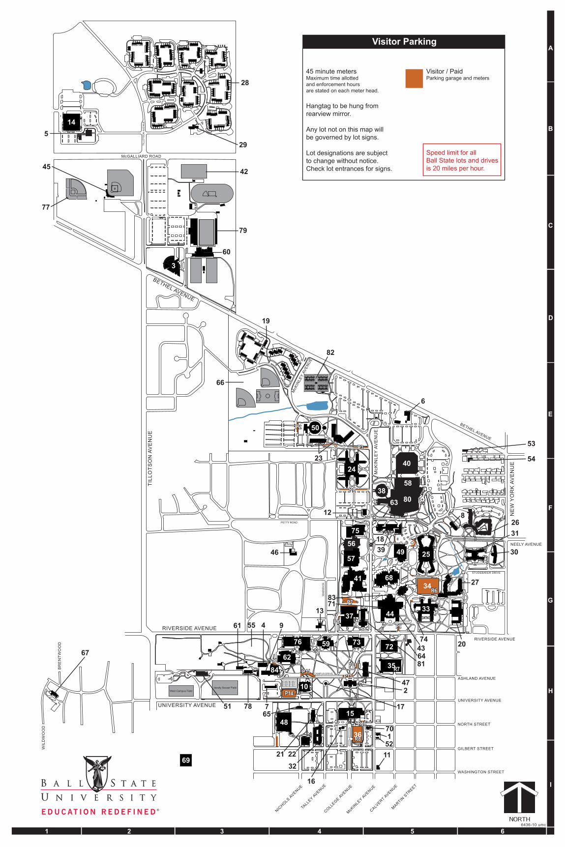
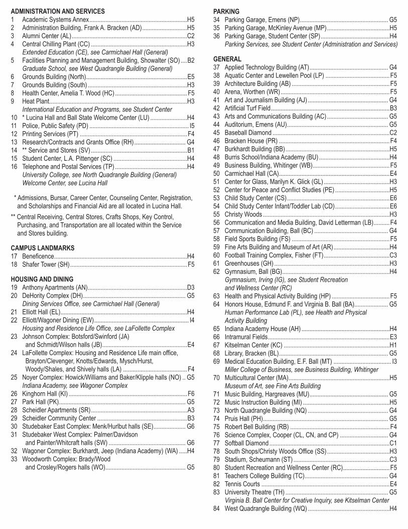
Ball State University Spill Prevention, Control, and Countermeasure (SPCC) Plan
-A 2-
Figure A-2: Facility Diagram(s).
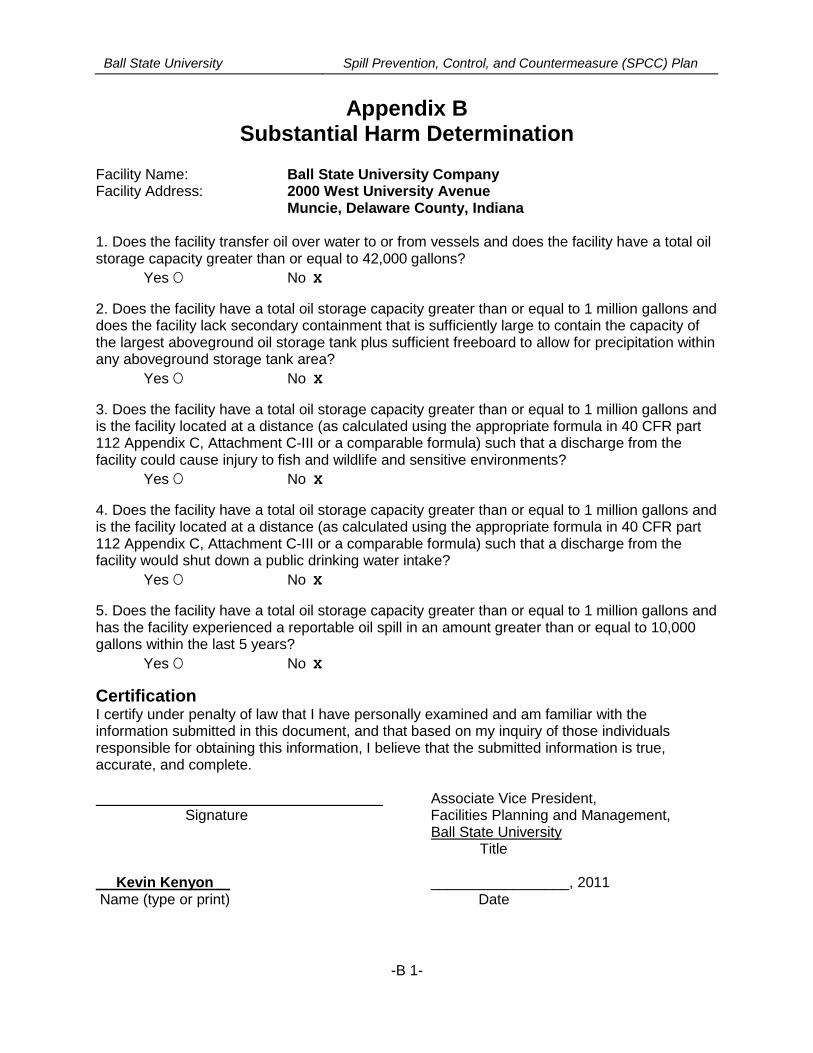
Ball State University Spill Prevention, Control, and Countermeasure (SPCC) Plan
-B 1-
Appendix BSubstantial Harm Determination
Facility Name: Ball State University CompanyFacility Address: 2000 West University Avenue
Muncie, Delaware County, Indiana
1. Does the facility transfer oil over water to or from vessels and does the facility have a total oilstorage capacity greater than or equal to 42,000 gallons?
Yes O No X
2. Does the facility have a total oil storage capacity greater than or equal to 1 million gallons anddoes the facility lack secondary containment that is sufficiently large to contain the capacity ofthe largest aboveground oil storage tank plus sufficient freeboard to allow for precipitation withinany aboveground storage tank area?
Yes O No X
3. Does the facility have a total oil storage capacity greater than or equal to 1 million gallons andis the facility located at a distance (as calculated using the appropriate formula in 40 CFR part112 Appendix C, Attachment C-III or a comparable formula) such that a discharge from thefacility could cause injury to fish and wildlife and sensitive environments?
Yes O No X
4. Does the facility have a total oil storage capacity greater than or equal to 1 million gallons andis the facility located at a distance (as calculated using the appropriate formula in 40 CFR part112 Appendix C, Attachment C-III or a comparable formula) such that a discharge from thefacility would shut down a public drinking water intake?
Yes O No X
5. Does the facility have a total oil storage capacity greater than or equal to 1 million gallons andhas the facility experienced a reportable oil spill in an amount greater than or equal to 10,000gallons within the last 5 years?
Yes O No X
CertificationI certify under penalty of law that I have personally examined and am familiar with theinformation submitted in this document, and that based on my inquiry of those individualsresponsible for obtaining this information, I believe that the submitted information is true,accurate, and complete.
Associate Vice President,Signature Facilities Planning and Management,
Ball State UniversityTitle
Kevin Kenyon _________________, 2011Name (type or print) Date
Ball State University Spill Prevention, Control, and Countermeasure (SPCC) Plan
-C 1-
APPENDIX CFacility Inspection Checklists
The following checklists are to be used for monthly and annual facility-conducted inspections.Completed checklists must be signed by the inspector and maintained at the facility, with thisSPCC Plan, for at least three years.
BSU Tank_CSA Checklists (final).pdf
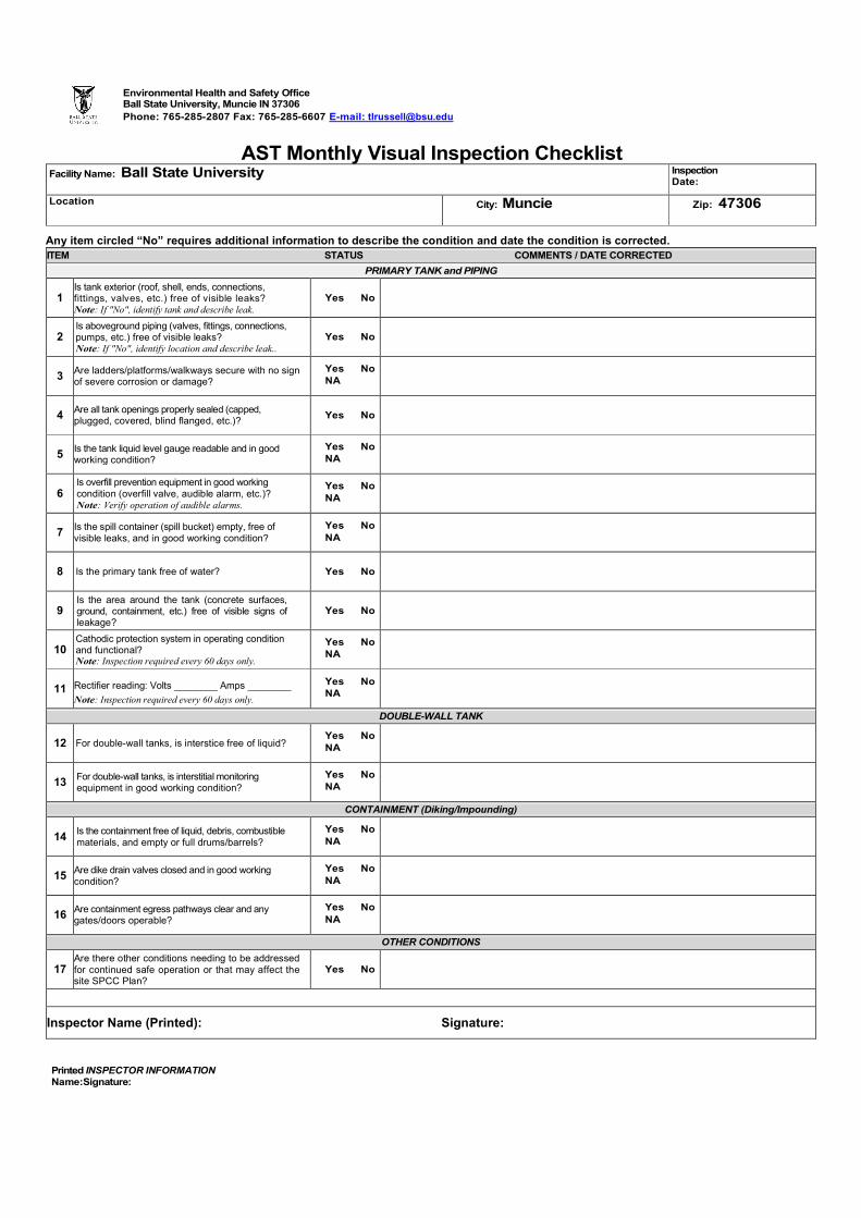
Printed INSPECTOR INFORMATIONName:Signature:
Environmental Health and Safety OfficeBall State University, Muncie IN 37306
Phone: 765-285-2807 Fax: 765-285-6607 E-mail: [email protected]
AST Monthly Visual Inspection ChecklistFacility Name: Ball State University Inspection
Date:
Location City: Muncie Zip: 47306
Any item circled “No” requires additional information to describe the condition and date the condition is corrected.
ITEM STATUS COMMENTS / DATE CORRECTED
PRIMARY TANK and PIPING
1Is tank exterior (roof, shell, ends, connections,fittings, valves, etc.) free of visible leaks?Note: If "No", identify tank and describe leak.
Yes No
2Is aboveground piping (valves, fittings, connections,pumps, etc.) free of visible leaks?Note: If "No", identify location and describe leak..
Yes No
3Are ladders/platforms/walkways secure with no signof severe corrosion or damage?
Yes NoNA
4Are all tank openings properly sealed (capped,plugged, covered, blind flanged, etc.)?
Yes No
5Is the tank liquid level gauge readable and in goodworking condition?
Yes NoNA
6Is overfill prevention equipment in good workingcondition (overfill valve, audible alarm, etc.)?Note: Verify operation of audible alarms.
Yes NoNA
7Is the spill container (spill bucket) empty, free ofvisible leaks, and in good working condition?
Yes NoNA
8 Is the primary tank free of water? Yes No
9Is the area around the tank (concrete surfaces,ground, containment, etc.) free of visible signs ofleakage?
Yes No
10Cathodic protection system in operating conditionand functional?Note: Inspection required every 60 days only.
Yes NoNA
11 Rectifier reading: Volts ________ Amps ________
Note: Inspection required every 60 days only.
Yes NoNA
DOUBLE-WALL TANK
12 For double-wall tanks, is interstice free of liquid?Yes NoNA
13For double-wall tanks, is interstitial monitoringequipment in good working condition?
Yes NoNA
CONTAINMENT (Diking/Impounding)
14Is the containment free of liquid, debris, combustiblematerials, and empty or full drums/barrels?
Yes NoNA
15Are dike drain valves closed and in good workingcondition?
Yes NoNA
16Are containment egress pathways clear and anygates/doors operable?
Yes No
NA
OTHER CONDITIONS
17Are there other conditions needing to be addressedfor continued safe operation or that may affect thesite SPCC Plan?
Yes No
Inspector Name (Printed): Signature:
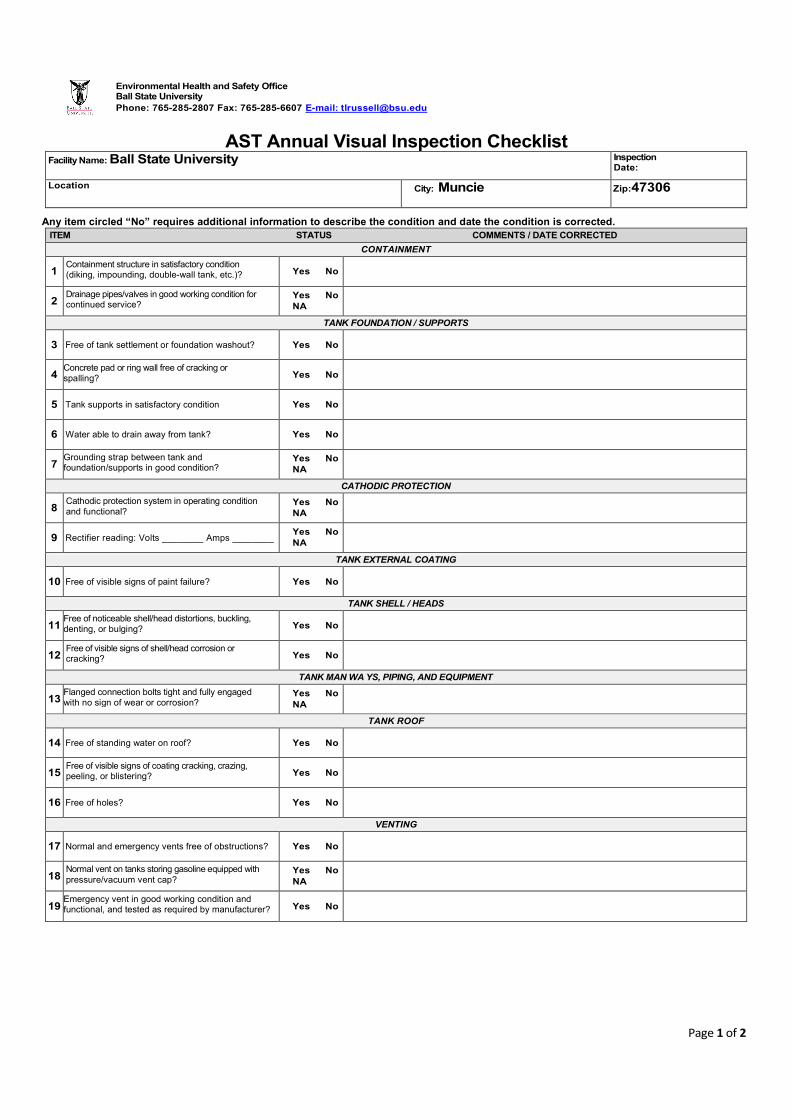
Page 1 of 2
Environmental Health and Safety OfficeBall State University
Phone: 765-285-2807 Fax: 765-285-6607 E-mail: [email protected]
AST Annual Visual Inspection ChecklistFacility Name: Ball State University Inspection
Date:
Location City: Muncie Zip:47306
Any item circled “No” requires additional information to describe the condition and date the condition is corrected.
ITEM STATUS COMMENTS / DATE CORRECTED
CONTAINMENT
1Containment structure in satisfactory condition(diking, impounding, double-wall tank, etc.)? Yes No
2Drainage pipes/valves in good working condition forcontinued service?
Yes NoNA
TANK FOUNDATION / SUPPORTS
3 Free of tank settlement or foundation washout? Yes No
4Concrete pad or ring wall free of cracking orspalling? Yes No
5 Tank supports in satisfactory condition Yes No
6 Water able to drain away from tank? Yes No
7Grounding strap between tank andfoundation/supports in good condition?
Yes NoNA
CATHODIC PROTECTION
8Cathodic protection system in operating conditionand functional?
Yes NoNA
9 Rectifier reading: Volts ________ Amps ________Yes NoNA
TANK EXTERNAL COATING
10 Free of visible signs of paint failure? Yes No
TANK SHELL / HEADS
11Free of noticeable shell/head distortions, buckling,denting, or bulging? Yes No
12Free of visible signs of shell/head corrosion orcracking? Yes No
TANK MAN WA YS, PIPING, AND EQUIPMENT
13Flanged connection bolts tight and fully engagedwith no sign of wear or corrosion?
Yes NoNA
TANK ROOF
14 Free of standing water on roof? Yes No
15Free of visible signs of coating cracking, crazing,peeling, or blistering? Yes No
16 Free of holes? Yes No
VENTING
17 Normal and emergency vents free of obstructions? Yes No
18Normal vent on tanks storing gasoline equipped withpressure/vacuum vent cap?
Yes NoNA
19Emergency vent in good working condition andfunctional, and tested as required by manufacturer? Yes No
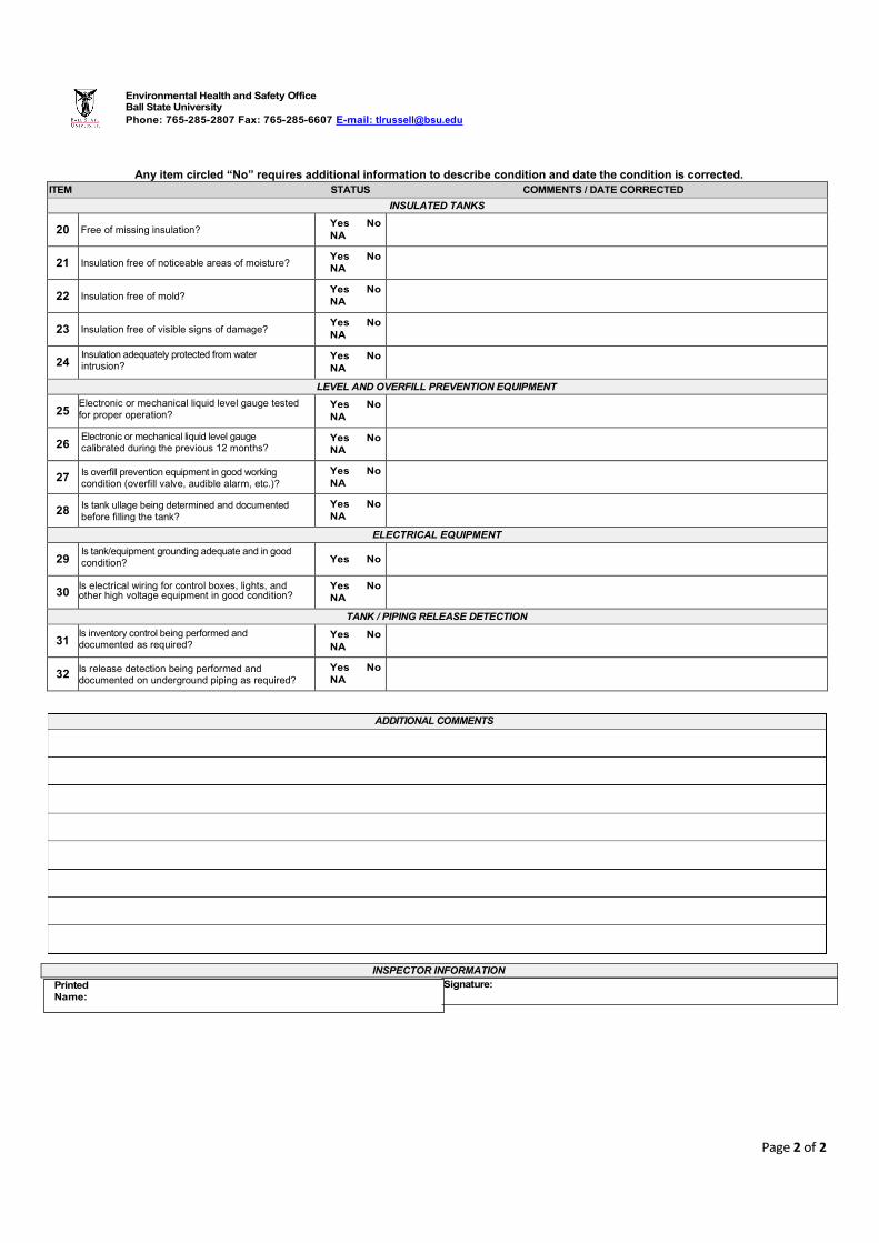
Page 2 of 2
Environmental Health and Safety OfficeBall State University
Phone: 765-285-2807 Fax: 765-285-6607 E-mail: [email protected]
Any item circled “No” requires additional information to describe condition and date the condition is corrected.
ITEM STATUS COMMENTS / DATE CORRECTED
INSULATED TANKS
20 Free of missing insulation?Yes NoNA
21 Insulation free of noticeable areas of moisture?Yes NoNA
22 Insulation free of mold?Yes NoNA
23 Insulation free of visible signs of damage?Yes NoNA
24Insulation adequately protected from waterintrusion?
Yes NoNA
LEVEL AND OVERFILL PREVENTION EQUIPMENT
25Electronic or mechanical liquid level gauge testedfor proper operation?
Yes NoNA
26Electronic or mechanical liquid level gaugecalibrated during the previous 12 months?
Yes NoNA
27 Is overfill prevention equipment in good workingcondition (overfill valve, audible alarm, etc.)?
Yes NoNA
28Is tank ullage being determined and documentedbefore filling the tank?
Yes NoNA
ELECTRICAL EQUIPMENT
29Is tank/equipment grounding adequate and in goodcondition? Yes No
30Is electrical wiring for control boxes, lights, andother high voltage equipment in good condition?
Yes NoNA
TANK / PIPING RELEASE DETECTION
31Is inventory control being performed anddocumented as required?
Yes NoNA
32Is release detection being performed anddocumented on underground piping as required?
Yes NoNA
INSPECTOR INFORMATION
Signature:
ADDITIONAL COMMENTS
PrintedName:
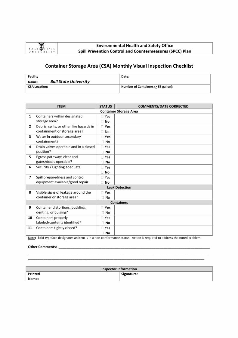
Environmental Health and Safety OfficeSpill Prevention Control and Countermeasures (SPCC) Plan
Container Storage Area (CSA) Monthly Visual Inspection Checklist
Facility
Name: Ball State UniversityDate:
CSA Location: Number of Containers (> 55 gallon):
ITEM STATUS COMMENTS/DATE CORRECTED
Container Storage Area
1 Containers within designatedstorage area?
Yes
No
2 Debris, spills, or other fire hazards incontainment or storage area?
Yes
No
3 Water in outdoor secondarycontainment?
Yes
No
4 Drain valves operable and in a closedposition?
Yes
No
5 Egress pathways clear andgates/doors operable?
Yes
No
6 Security / Lighting adequate Yes
No
7 Spill preparedness and controlequipment available/good repair
Yes
No
Leak Detection
8 Visible signs of leakage around thecontainer or storage area?
Yes
No
Containers
9 Container distortions, buckling,denting, or bulging?
Yes
No
10 Containers properlylabeled/contents identified?
Yes
No
11 Containers tightly closed? Yes
NoNote: Bold typeface designates an item is in a non-conformance status. Action is required to address the noted problem.
Other Comments: ______________________________________________________________________________
_____________________________________________________________________________________________
___________________________________________________________________________________________
Inspector Information
PrintedName:
Signature:
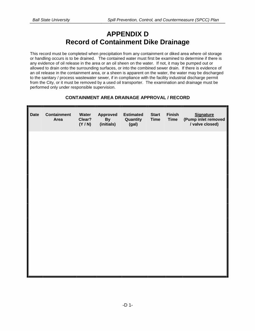
Ball State University Spill Prevention, Control, and Countermeasure (SPCC) Plan
-D 1-
APPENDIX DRecord of Containment Dike Drainage
This record must be completed when precipitation from any containment or diked area where oil storageor handling occurs is to be drained. The contained water must first be examined to determine if there isany evidence of oil release in the area or an oil sheen on the water. If not, it may be pumped out orallowed to drain onto the surrounding surfaces, or into the combined sewer drain. If there is evidence ofan oil release in the containment area, or a sheen is apparent on the water, the water may be dischargedto the sanitary / process wastewater sewer, if in compliance with the facility industrial discharge permitfrom the City, or it must be removed by a used oil transporter. The examination and drainage must beperformed only under responsible supervision.
CONTAINMENT AREA DRAINAGE APPROVAL / RECORD
Date ContainmentArea
WaterClear?(Y / N)
ApprovedBy
(initials)
EstimatedQuantity
(gal)
StartTime
FinishTime
Signature(Pump inlet removed
/ valve closed)

Ball State University Spill Prevention, Control, and Countermeasure (SPCC) Plan
-E 1-
APPENDIX ERecord of Annual Discharge Prevention
Briefings and Training
Ball State University management has instructed oil-handling facility personnel in the operationand maintenance of oil pollution prevention equipment, discharge procedure protocols,applicable pollution control laws, rules and regulations, general facility operations, and thecontent of this SPCC Plan.
Briefings to reinforce discharge prevention will be scheduled and conducted by Ball StateUniversity for operating personnel involved in oil handling or use activities at regular intervals (atleast annually) as necessary to ensure continued familiarity with this SPCC Plan. The briefingswill also highlight and describe known discharge events or failures, malfunctioning components,and recently implemented precautionary measures and best practices. Personnel will also beinstructed in operation and maintenance of equipment to prevent the discharge of oil, and inapplicable pollution laws, rules, and regulations. Facility operators and other personnel will havean opportunity during the briefings to share recommendations concerning health, safety, andenvironmental issues encountered during facility operations.
The form illustrated on the next page, or an electronic tracking format containing similarinformation, will be maintained to document and assure that all necessary employees receivesuch briefings at least once a year.
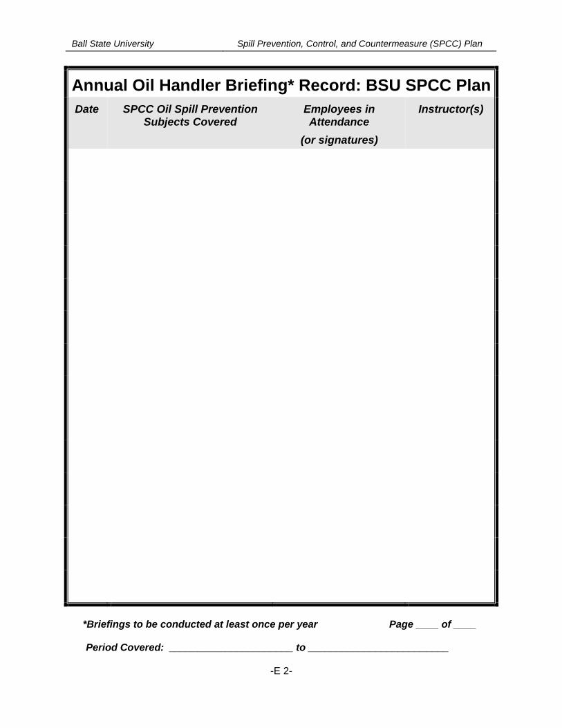
Ball State University Spill Prevention, Control, and Countermeasure (SPCC) Plan
-E 2-
Annual Oil Handler Briefing* Record: BSU SPCC Plan
Date SPCC Oil Spill PreventionSubjects Covered
Employees inAttendance
(or signatures)
Instructor(s)
*Briefings to be conducted at least once per year Page ____ of ____
Period Covered: ______________________ to _________________________
Ball State University Spill Prevention, Control, and Countermeasure (SPCC) Plan
-F 1-
APPENDIX FCalculation of Secondary Containment Capacity
The design 24-hour, 25-year storm at this location (Muncie, Indiana) is 4.65 inches.
This Appendix relates the secondary containment capacity of the significant bulk oil storagelocations on the BSU campus where vaults are used for containment purposes:
Used Oil and Lubricant Tanks (SV Bus Garage):
Four (4) 275 gallon oil tanks are located in the enclosed annex structure to the SV Building.The structure is completely enclosed.
Calculations:Capacity of Tanks within the Vault Area:Tanks = 275 gallons each = 1,100 gallons
Concrete Vault Dimensions:Vault slab footprint = 17 feet x 7.5 feet = 127.5 ft2
Vault wall height = 2 feet (curb at door)Vault volume = 127.5 ft2 x 2 ft = 255 ft3 x 7.48 gal/ft3 = 1,907 gallons
Total Containment Volume: 1,907 gallons
Displacement Volume of Tanks (elliptical – assume a cuboid for conservative approach:Tank length = 5 feet; Tank end diameter = 27 inches2 feet X 2.25 feet x 5 feet = 22.5 ft3 x 7.48 gal/ft3 = 169 gallons x 4 tanks = 676 gallons
Displacement Volume for piping, supports, etc.: 1 ft3 X 7.48 gallons/ ft3 = 7.5 gallons
Total Displacement Volume: 676-7.5 = 668.5 gallons
Available Containment Capacity for Precipitation or Spill Containment: 1,907 gallons –143.5 gallons = 1,223 gallons.
Conclusion: The vault therefore provides 1,223 gallons of available liquid storagecapacity. This far exceeds the capacity necessary to contain the volume form thecomplete failure of the largest tank in the containment (275 gallons). The tanks andcontainment are completely enclosed and under roof so no accommodation forprecipitation is necessary.
Waste Accumulation Room (Cooper Science Building):
The largest container stored in this room is 55-gallons which is greater than the volume of 10%of all containers that may be stored in the accumulation room.
Calculations:The containment room is triangular in shape with dimensions of 33 feet x 15 feet = 33/2x 15 = 247.5 ft2. A portion of the room is outside of the containment curb, however, and
Ball State University Spill Prevention, Control, and Countermeasure (SPCC) Plan
-F 2-
has dimensions of 6 feet by 9 feet or an area of 3/2 x 9 = 13.5 ft2. This leaves acontainment area of 247.5-13.5 = 234 ft2. The curb is 4 inches in height, so 234 ft2 x0.33 ft = 77.2 ft3. The total containment capacity of the room is then 77.2 ft3 x 7.48 gal/ft3
= 577 gallons. Displacement includes only six (6) chemical storage cabinets in thecontainment room area. These are approximately 48 inches x 18 inches in floordimension so 4 ft x 1.5 ft = 6 ft2 each for a total of 36 ft2 x 0.33 = 12 ft3 or 12 ft3 x 7.48gal/ft3 = 90 gallons.
Conclusion: Based on the above the available containment volume for the room is 577gallons with a displacement volume of 90 gallons. This leaves an available containmentcapacity of 487 gallons which far exceeds the minimum required capacity of 55 gallons.
Waste Shed (North campus):
The maximum storage volume of the roofed and fully enclosed waste shed is twenty (20) 55-gallon drums for a total of 1100 gallons. The shed is 8 foot x 22 foot in dimension with a gratedcontainment floor that is 7 inches deep.
Calculations:8 feet x 22 feet x 0.583 feet = 103 ft3 x 7.48 gallons/ft3 = 770 gallons of total containmentcapacity. No displacement is involved as all storage is above the elevation of thecontainment sump grating. Therefore the available containment capacity remains at 770gallons.
Conclusion:The required containment volume is 10% of the total storage capacity or that of thelargest container which, in this instance, would be 110 gallons. The available 770gallons of available containment far exceeds that volume.
Generator Day Tank Containment (example – Service and Stores generator room):
This 564-gallon capacity steel tank is located inside an enclosed annex with a roof and aconcrete floor slab elevation that is slightly lower than the surrounding terrain. The containmentvault floor slab is 15 feet by 17 feet in dimension with an effective containment wall of 8 inches(0.66 feet) height at its lowest point. A small blind collection sump that is 6 inches deep and 12inches in diameter is present near the tank. The fuel storage tank is elevated on a pad withdimensions of 3.5 ft x 6 ft, and the generator is on an elevated pad of 5 ft x 12 ft, both with aheight of 8 inches above the floor slab top elevation.
Calculations:Total containment capacity: 15 ft x 17 ft x 0.66 ft = 168 ft3 x 7.48 gallons/ft3 =1,256 gallons. The sump has an additional capacity of: (0.5 ft)2 x 0.5 ft x 3.14 = 0.39 ft3
x 7.48 gallons/ft3 = 2.92 gallons. The total containment capacity is then 1,259 gallons.
Displacement: Tank pad: 3.5 ft x 6 ft x 0.66 ft = 13.8 ft3 x 7.48 gallons/ft3 = 104 gallonsGenerator pad: 5 ft x 12 ft x 0.66 ft = 39.6 x 7.48 gallons/ft3 = 296 gallons, so the totaldisplacement is 104+296 = 400 gallons.
Ball State University Spill Prevention, Control, and Countermeasure (SPCC) Plan
-F 3-
Conclusion:The total available containment capacity = 1259 - 400 = 859 gallons. Since thisavailable capacity exceeds the required 564-gallon capacity of the tank, the containmentcapacity is adequate.
[The above is an example of the containment capacities of the gensets using vaults ascontainment for the fuel tanks.]
Ball State University Spill Prevention, Control, and Countermeasure (SPCC) Plan
-G 1-
APPENDIX G
Records of Certified Tank Inspections, Tank Integrity andPressure Tests
Copies are attached here, or located in a separate file in the office where this SPCC Plan ismaintained, of records of tank integrity and pressure tests, repairs or modifications, and recordsof tank inspections and findings by independent certified tank inspectors. The following Tableprovides an index to the records or certifications maintained.
Index of Tank Inspection, Repair, or Test Records
Date Tank Performed by(vendor or firm
name)
Description of Record, Inspection, or Test
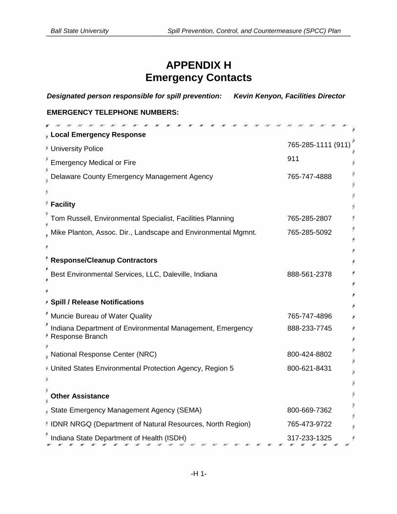
Ball State University Spill Prevention, Control, and Countermeasure (SPCC) Plan
-H 1-
APPENDIX HEmergency Contacts
Designated person responsible for spill prevention: Kevin Kenyon, Facilities Director
EMERGENCY TELEPHONE NUMBERS:
Local Emergency Response
University Police765-285-1111 (911)
Emergency Medical or Fire911
Delaware County Emergency Management Agency 765-747-4888
Facility
Tom Russell, Environmental Specialist, Facilities Planning 765-285-2807
Mike Planton, Assoc. Dir., Landscape and Environmental Mgmnt. 765-285-5092
Response/Cleanup Contractors
Best Environmental Services, LLC, Daleville, Indiana 888-561-2378
Spill / Release Notifications
Muncie Bureau of Water Quality
Indiana Department of Environmental Management, EmergencyResponse Branch
765-747-4896
888-233-7745
National Response Center (NRC) 800-424-8802
United States Environmental Protection Agency, Region 5 800-621-8431
Other Assistance
State Emergency Management Agency (SEMA) 800-669-7362
IDNR NRGQ (Department of Natural Resources, North Region) 765-473-9722
Indiana State Department of Health (ISDH) 317-233-1325
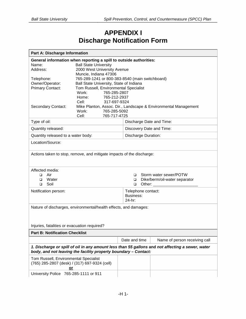
Ball State University Spill Prevention, Control, and Countermeasure (SPCC) Plan
-H 1-
APPENDIX IDischarge Notification Form
Part A: Discharge Information
General information when reporting a spill to outside authorities:Name: Ball State UniversityAddress: 2000 West University Avenue
Muncie, Indiana 47306Telephone: 765-289-1241 or 800-383-8540 (main switchboard)Owner/Operator: Ball State University, State of IndianaPrimary Contact: Tom Russell, Environmental Specialist
Work: 765-285-2807Home: 765-212-2937Cell: 317-697-9324
Secondary Contact: Mike Planton, Assoc. Dir., Landscape & Environmental ManagementWork: 765-285-5092Cell: 765-717-4725
Type of oil: Discharge Date and Time:
Quantity released: Discovery Date and Time:
Quantity released to a water body: Discharge Duration:
Location/Source:
Actions taken to stop, remove, and mitigate impacts of the discharge:
Affected media: Air Water Soil
Storm water sewer/POTW Dike/berm/oil-water separator Other: ____________________
Notification person: Telephone contact:Business:24-hr:
Nature of discharges, environmental/health effects, and damages:
Injuries, fatalities or evacuation required?
Part B: Notification Checklist
Date and time Name of person receiving call
1. Discharge or spill of oil in any amount less than 55 gallons and not affecting a sewer, waterbody, and not leaving the facility property boundary – Contact:
Tom Russell, Environmental Specialist(765) 285-2807 (desk) / (317) 697-9324 (cell)
or
University Police 765-285-1111 or 911
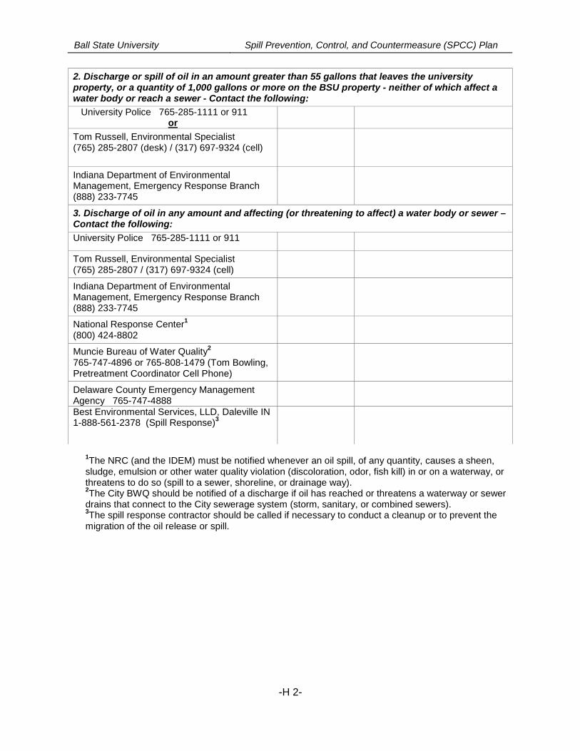
Ball State University Spill Prevention, Control, and Countermeasure (SPCC) Plan
-H 2-
2. Discharge or spill of oil in an amount greater than 55 gallons that leaves the universityproperty, or a quantity of 1,000 gallons or more on the BSU property - neither of which affect awater body or reach a sewer - Contact the following:
University Police 765-285-1111 or 911or
Tom Russell, Environmental Specialist(765) 285-2807 (desk) / (317) 697-9324 (cell)
Indiana Department of EnvironmentalManagement, Emergency Response Branch(888) 233-7745
3. Discharge of oil in any amount and affecting (or threatening to affect) a water body or sewer –Contact the following:
University Police 765-285-1111 or 911
Tom Russell, Environmental Specialist(765) 285-2807 / (317) 697-9324 (cell)
Indiana Department of EnvironmentalManagement, Emergency Response Branch(888) 233-7745
National Response Center1
(800) 424-8802
Muncie Bureau of Water Quality2
765-747-4896 or 765-808-1479 (Tom Bowling,Pretreatment Coordinator Cell Phone)
Delaware County Emergency ManagementAgency 765-747-4888Best Environmental Services, LLD, Daleville IN1-888-561-2378 (Spill Response)
3
1The NRC (and the IDEM) must be notified whenever an oil spill, of any quantity, causes a sheen,
sludge, emulsion or other water quality violation (discoloration, odor, fish kill) in or on a waterway, orthreatens to do so (spill to a sewer, shoreline, or drainage way).2The City BWQ should be notified of a discharge if oil has reached or threatens a waterway or sewer
drains that connect to the City sewerage system (storm, sanitary, or combined sewers).3The spill response contractor should be called if necessary to conduct a cleanup or to prevent the
migration of the oil release or spill.
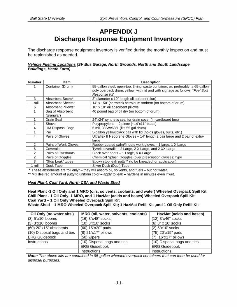
Ball State University Spill Prevention, Control, and Countermeasure (SPCC) Plan
-J 1-
APPENDIX JDischarge Response Equipment Inventory
The discharge response equipment inventory is verified during the monthly inspection and mustbe replenished as needed.
Vehicle Fueling Locations (SV Bus Garage, North Grounds, North and South LandscapeBuildings, Heath Farm)
Number Item Description1 Container (Drum) 55-gallon steel, open-top, 3-ring waste container, or, preferably, a 65-gallon
poly overpack drum, yellow, with lid and with signage as follows: “Fuel SpillResponse Kit”
3 Absorbent Socks* 3” diameter x 10” length oil sorbent (blue)1 roll Absorbent Sheets* 14” x 150’ (serrated) petroleum sorbent (on bottom of drum)
6 Absorbent Pillows* 10” x 10” oil absorbent pillows1 Bag of Absorbent
(granular)40 pound bag of oil dry (on bottom of drum)
1 Drain Seal 24”x24” synthetic seal for drain cover (in cardboard box)1 Shovel Polypropylene - 2 piece (~14”x11” blade)4 HM Disposal Bags 6 mil, 38”Wx68”L (fits 55 gal drum)1 Pail 5-gallon yellow/black pail with lid (holds gloves, suits, etc.)4 Pairs of Gloves Ultraflex II Neoprene Gloves – 14” length 2 pair large and 2 pair of extra-
large2 Pairs of Work Gloves Rubber coated palm/fingers work gloves – 1 large, 1 X Large6 Coveralls Tyvek coveralls – 2 Large, 2 X Large, and 2 XX Large2 Pairs of Overboots Black over boots – 1 Large, a X-Large2 Pairs of Goggles Chemical Splash Goggles (over prescription glasses) type3 “Stop Leak” tubes Epoxy stop leak putty** (to be kneaded for application)
1 roll Duck Tape Silver Duck (Duct) Tape
* These absorbents are “oil only” – they will absorb oil, solvents, and fuels – but not water.** Mix desired amount of putty to uniform color – apply to leak – hardens in minutes even if wet.
Heat Plant, Coal Yard, North CSA and Waste Shed
Heat Plant -1 Oil Only and 1 MRO (oils, solvents, coolants, and water) Wheeled Overpack Spill KitChill Plant - 1 Oil Only, 1 MRO, and 1 HazMat (acids and bases) Wheeled Overpack Spill KitCoal Yard – 1 Oil Only Wheeled Overpack Spill KitWaste Shed – 1 MRO Wheeled Overpack Spill Kit; 1 HazMat Refill Kit ,and 1 Oil Only Refill Kit
Oil Only (no water abs.) MRO (oil, water, solvents, coolants) HazMat (acids and bases)(3) 5”x10’ booms (16) 3”x48” socks (12) 3”x46” socks(3) 3”x10’ booms (10) 3”x10’ socks (6) 3” x 10’ socks(60) 20”x15” absobents (60) 15”x20” pads (2) 5”x10’ socks(10) Disposal bags and ties (8) 21”x17” pillows (75) 20”x15” padsERG Guidebook (50) wipers (7) 16”x17” pillowsInstructions (10) Disposal bags and ties (10) Disposal bags and ties
ERG Guidebook ERG GuidebookInstructions Instructions
Note: The above kits are contained in 95-gallon wheeled overpack containers that can then be used fordisposal purposes.
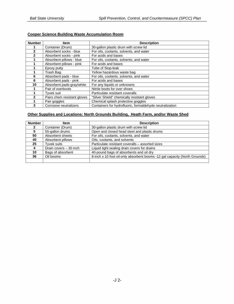
Ball State University Spill Prevention, Control, and Countermeasure (SPCC) Plan
-J 2-
Cooper Science Building Waste Accumulation Room
Number Item Description1 Container (Drum) 30-gallon plastic drum with screw lid2 Absorbent socks - blue For oils, coolants, solvents, and water2 Absorbent socks - pink For acids and bases1 Absorbent pillows - blue For oils, coolants, solvents, and water1 Absorbent pillows - pink For acids and bases1 Epoxy putty Tube of Stop-leak1 Trash Bag Yellow hazardous waste bag6 Absorbent pads - blue For oils, coolants, solvents, and water6 Absorbent pads - pink For acids and bases10 Absorbent pads-gray/white For any liquids or unknowns1 Pair of overboots Nitrile boots for over shoes1 Tyvek suit Particulate resistant coveralls2 Pairs chem resistant gloves “Silver Shield” chemically resistant gloves1 Pair goggles Chemical splash protective goggles3 Corrosive neutralizers Containers for hydrofluoric, formaldehyde neutralization
Other Supplies and Locations: North Grounds Building, Heath Farm, and/or Waste Shed
Number Item Description2 Container (Drum) 30-gallon plastic drum with screw lid5 55-gallon drums Open and closed head steel and plastic drums50 Absorbent sheets For oils, coolants, solvents, and water40 Absorbent pillows Oils, coolants, and solvents25 Tyvek suits Particulate resistant coveralls – assorted sizes4 Drain covers – 30 inch Liquid tight sealing drain covers for drains10 Bags of absorbent 40-pound bags of absorbents and oil dry36 Oil booms 8-inch x 10 foot oil-only absorbent booms -12 gal capacity (North Grounds)
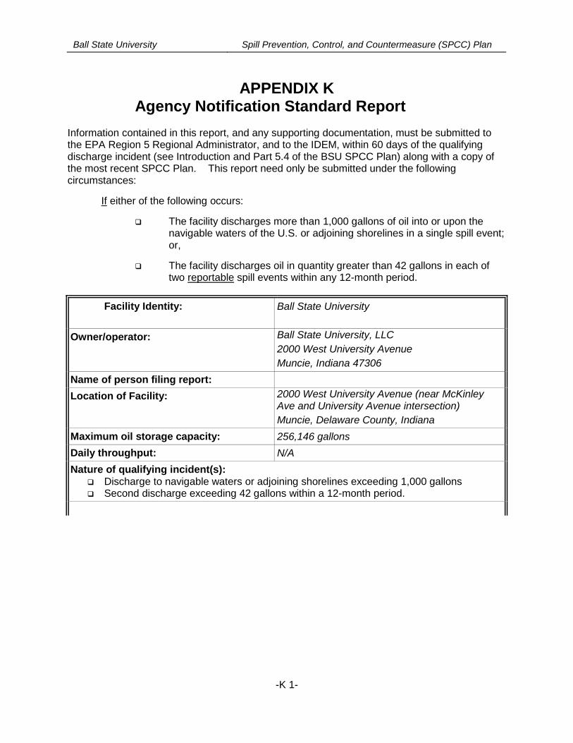
Ball State University Spill Prevention, Control, and Countermeasure (SPCC) Plan
-K 1-
APPENDIX KAgency Notification Standard Report
Information contained in this report, and any supporting documentation, must be submitted tothe EPA Region 5 Regional Administrator, and to the IDEM, within 60 days of the qualifyingdischarge incident (see Introduction and Part 5.4 of the BSU SPCC Plan) along with a copy ofthe most recent SPCC Plan. This report need only be submitted under the followingcircumstances:
If either of the following occurs:
The facility discharges more than 1,000 gallons of oil into or upon thenavigable waters of the U.S. or adjoining shorelines in a single spill event;or,
The facility discharges oil in quantity greater than 42 gallons in each oftwo reportable spill events within any 12-month period.
Facility Identity: Ball State University
Owner/operator: Ball State University, LLC
2000 West University Avenue
Muncie, Indiana 47306
Name of person filing report:
Location of Facility: 2000 West University Avenue (near McKinleyAve and University Avenue intersection)
Muncie, Delaware County, Indiana
Maximum oil storage capacity: 256,146 gallons
Daily throughput: N/A
Nature of qualifying incident(s): Discharge to navigable waters or adjoining shorelines exceeding 1,000 gallons Second discharge exceeding 42 gallons within a 12-month period.
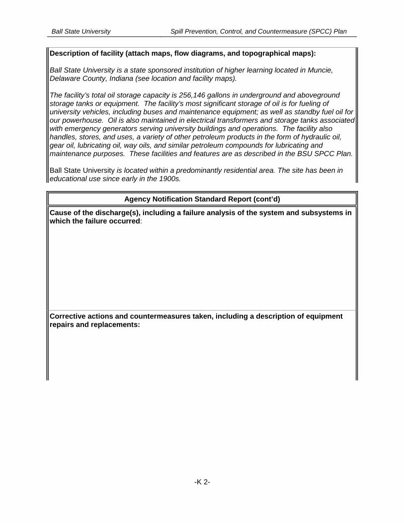
Ball State University Spill Prevention, Control, and Countermeasure (SPCC) Plan
-K 2-
Description of facility (attach maps, flow diagrams, and topographical maps):
Ball State University is a state sponsored institution of higher learning located in Muncie,Delaware County, Indiana (see location and facility maps).
The facility’s total oil storage capacity is 256,146 gallons in underground and abovegroundstorage tanks or equipment. The facility’s most significant storage of oil is for fueling ofuniversity vehicles, including buses and maintenance equipment; as well as standby fuel oil forour powerhouse. Oil is also maintained in electrical transformers and storage tanks associatedwith emergency generators serving university buildings and operations. The facility alsohandles, stores, and uses, a variety of other petroleum products in the form of hydraulic oil,gear oil, lubricating oil, way oils, and similar petroleum compounds for lubricating andmaintenance purposes. These facilities and features are as described in the BSU SPCC Plan.
Ball State University is located within a predominantly residential area. The site has been ineducational use since early in the 1900s.
Agency Notification Standard Report (cont’d)
Cause of the discharge(s), including a failure analysis of the system and subsystems inwhich the failure occurred:
Corrective actions and countermeasures taken, including a description of equipmentrepairs and replacements:
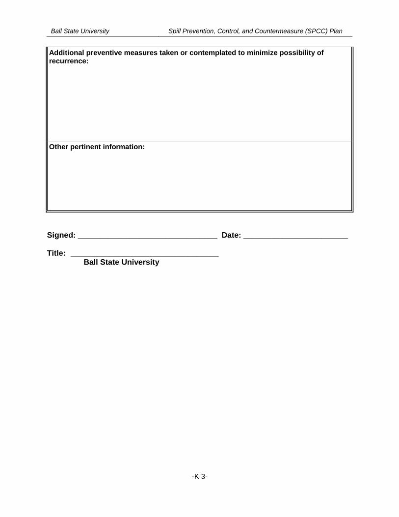
Ball State University Spill Prevention, Control, and Countermeasure (SPCC) Plan
-K 3-
Additional preventive measures taken or contemplated to minimize possibility ofrecurrence:
Other pertinent information:
Signed: ________________________________ Date: ________________________
Title: __________________________________Ball State University