ballast direct shear testing - timothy d. starktstark.net/wp-content/uploads/2015/08/cp0122.pdf ·...
TRANSCRIPT

BALLAST DIRECT SHEAR TESTING
Timothy D. Stark, Ph.D., P.E., D.GE Professor of Civil and Environmental Engineering
University of Illinois at Urbana-Champaign Urbana, Illinois 61801
Robert H. Swan, Jr. Associate Teaching Professor of Civil Engineering
Drexel University 3141 Chestnut Street
Philadelphia, PA 19104 [email protected]
and
Zehong Yuan, Ph.D. President and Technical Director
4405 International Boulevard SGI Testing Services, LLC
Norcross, GA 30093 [email protected]
ABSTRACT This paper summarizes the appropriate equipment and test procedure for ballast shear strength testing using the direct shear method (ASTM D3080 and D5321) and presents some typical results. To accomplish this ballast testing, a full-scale direct shear box was developed that can accommodate an approximately 1 m (3 feet) wide and 0.6 m (2 feet) deep specimen, which is much larger than current shear boxes used for ballast testing. This larger specimen size resulted in significant
differences in measured shear behavior and shear strength parameters. The shear strength properties of the ballast under typical as-placed conditions are determined herein using the new shear box and normal stresses applied through dead weight loading that are representative of railroad track conditions. Effects of direct shear specimen size and confining normal stress are demonstrated using a typical angular granite ballast and the results are compared to published ballast shear strength data.
1 Copyright © 2014 by ASME
Proceedings of the 2014 Joint Rail Conference JRC2014
April 2-4, 2014, Colorado Springs, CO, USA
JRC2014-3714

INTRODUCTION Ballast is a uniformly graded aggregate that provides support to track superstructure, i.e., crossties. As a result, it is the uppermost support system for the static and dynamic loads applied by passing trains. Understanding the compressibility, shear strength, and stiffness of ballast is important for assessing the support and distribution of the train loads. If the ballast particles degrade due to the applied static and dynamic loads, ballast fouling can occur causing a decrease in shear strength and stiffness and an increase in compressibility. The particle degradation is usually caused by fouling, particle breakage, and/or abrasion. The main objective of this study was to develop a shear box large enough to accommodate the large particle size frequently present in ballast. The shear box must be large enough so particle movement, breakage, dilation, friction, etc. can occur without significant boundary effects and large enough to impart a large shear displacement to investigate the effect(s) of particle breakage and/or abrasion on ballast shear strength and compressibility with increasing shear displacement. This paper summarizes: (i) prior ballast direct shear testing, (ii) various methods for determining the direct shear specimen size to minimize boundary effects on the test results, (iii) development of a new full-scale direct shear box (1 m wide and 0.6 m deep), (iv) typical test results using the new shear box, and (v) future testing with the new shear box including different levels of ballast fouling, geosynthetics, and ballast materials. PRIOR BALLAST DIRECT SHEAR TESTING Chiang [1] uses repeated load tests in a ballast box to investigate the effect of fouled ballast on compressibility which increased with increasing fouling amount. Han and Selig [2] also use ballast box tests to investigate the effect of fouling on ballast compressibility and also conclude that compressibility increases with increased fouling. More pertinent, Huang et al. [3], Dombrow et al. [4], and Boler [5] use a direct shear box developed for geosynthetics testing to
investigate ballast shear strength with and without fouling. This shear box was developed for use with ASTM D5321 and ASTM D6243 for testing of geosynthetics that have a macro structure, such as geonets, geogrids, and textured geomembranes. Huang et al. [3], Dombrow et al. [4], and Boler [5] use this shear box to investigate the strength and deformation characteristics of granite and limestone ballast subjected to different levels of fouling. These direct shear tests show clean ballast exhibits only a somewhat higher shear strength and shear strength somewhat decreased with increasing fouling. All of the fouled and clean ballast samples exhibit a significant cohesion intercept as shown below and a friction angle ranging from 40 to 48 degrees. The ballast specimen size used in the D5321/D6243 shear box in [3], [4], and [5] is: 0.30 m (1 ft) wide, 0.35 m (1.1 ft) long, and 0.22 m (0.75 ft) deep. REQUIRED DIRECT SHEAR SPECIMEN SIZE This section reviews various ASTM test methods to estimate the specimen size that should be used for ballast direct shear testing to minimize boundary effects on the measured shear strength and compressibility. It has been shown that if smaller specimens are used, the walls of the shear box can provide significant confinement that is not present in the field resulting in an overestimate of shear strength. ASTM D3080 ASTM D3080 [6] is the long standing test method for measuring the drained shear strength of soils using a direct shear apparatus. Sections 6.2.1 and 6.2.2 of D3080 state the minimum specimen width (W) for square specimens should not be less than ten (10) times the maximum particle size diameter (Dmax) and an initial total specimen thickness (T) of not less than six times the maximum particle diameter. In addition, Section 6.2.3 requires a specimen width to thickness ratio (W/T) of 2:1 or a thickness that is one-half the specimen width. These requirements are shown in Table 1.
2 Copyright © 2014 by ASME

TABLE 1 – ASTM REQUIRED DIRECT SHEAR SIZE
ASTM Test
Method
Specimen
Width (W)
Total Specimen Thickness
(T)
Depth of Each
Container (D)
Specimen Width to
Thickness (W/T)
D3080
>10*Dmax
>6*Dmax
2:1
D5321
>15*D85
>6*Dmax
D6243
>15*D85
>6*Dmax
ASTM D5321 ASTM D5321 [7] is the test method that was developed for geosynthetic interface shear testing because some geosynthetics have macro structure that are too large for inclusion in direct shear devices used with ASTM D3080. Passage of ASTM D5321 resulted in development of a number of larger commercially available shear boxes, similar to that used by Huang et al. [3], Dombrow et al. [4], and Boler [5] for their ballast testing. Specifically the shear box used in [3], [4], and [5] was designed and manufactured by the second author and purchased by the first author for geosynthetics testing at the University of Illinois at Urbana-Champaign. This device has the following dimensions: 0.30 m (1 ft) width, 0.35 m (1.1 ft) length, and 0.22 m (0.75 ft) depth. Section 6.1.1 of D5321 states the minimum specimen width (W) for square specimens should not be less than fifteen (15) times the grain diameter at 85% passing (D85) and the depth of each shear container that contains soil be six (6) times Dmax. These requirements are also shown in Table 1. ASTM D6243 ASTM D6243 [8] was developed for the interface and internal shear testing of Geosynthetic Clay Liners (GCLs) because of the many nuances in shear testing of GCLs, such as hydration normal stress, displacement rate, and GCL gripping surface. However, ASTM D6243 was developed to utilize the same shear box required by ASTM D5321. Section 6.1.1 of D6243 states the minimum specimen width for square specimens also
should not be less than fifteen (15) times D85 and depth of each shear container that contains soil be six (6) times Dmax. These requirements are the same as in ASTM D5321 and are also shown in Table 1. REQUIRED DIRECT SHEAR SPECIMEN SIZE This section describes the ballast material tested herein and the minimum specimen size using the ASTM specimen size requirements presented in Table 1. Ballast Material Tested Direct shear strength tests were performed on reconstituted clean granite ballast obtained from the Vulcan Materials Company Quarry near Atlanta, Georgia. The material tested has a Product Name of #4 Aggregate Material and is termed Railroad Ballast. This material is referred to as “#4 Aggregate Material” herein. The aggregate size ranges from about 50 mm (2 inches) to 19 mm (0.75 inches). The values of Dmax and D85 are 56 mm (2.2 inches) and 36 mm (1.4 inches), respectively. For each test, the ballast was hand tamped in place yielding an initial unit weight of 16.1 kN/m3 (102.8 pcf). This method of compaction was used in all of the ballast testing. Figure 1 shows the grain size distribution of the #4 Aggregate Material (which has a specific gravity of 2.63 when tested in accordance with ASTM C117). The granite aggregate size distribution is a little finer than the typical American Railway Engineering and Maintenance-of-Way Association (AREMA) No. 24 ballast gradation, which has a maximum size (Dmax) of 63.5 mm (2.5 in.), a minimum size (Dmin) of 25.4 mm (1 in.), and an average particle size corresponding to 50% passing by weight (D50) of approximately 45 mm (1.77 in.). The #4 Aggregate size distribution is in rough agreement with the granite aggregate size distribution used in the direct shear testing reported by Dombrow et al. [3] and Huang et al. [4]. The values of Dmax and D85 for the granite aggregate material testing in [3], [4], and [5] are 63 mm (2.5 inches) and 53 mm (2.1 inches), respectively. An initial unit weight of 15.1 kN/m3 (96.0 pcf) was used in the testing reported in [4].
3 Copyright © 2014 by ASME

FIGURE 1 – Grain size distribution of clean
granite ballast tested herein, tested in [4], and for AREMA No. 24.
Required Specimen Size This section describes the determination of direct shear specimen size required by applicable ASTM test methods as discussed in Table 1 for the granite #4 Aggregate Material tested herein and the granite ballast tested by Dumbrow et al. [4]. Table 2 shows the required dimensions for the two granite ballast gradations shown in Figure 1. For the #4 Aggregate tested herein, the shear box should have the following dimensions to ensure minimal boundary effects on the measured shear strength and compressibility parameters: 0.56 m (1.8 ft) width and a thickness of 0.336 m (1.1 ft). These dimensions significantly exceed the dimensions of the available D5321/D6243 shear box that typically have the following dimensions: 0.30 m (1 ft) width and and 0.22 m (0.75 ft) depth. Therefore a new full-scale shear box apparatus was developed herein. Based on the grain size distribution in Figure 1, the direct shear testing reported in [3], [4], and [5] should have used a shear box with the following dimensions to ensure minimal boundary effects on the measured shear strength and compressibility parameters: 0.795 m (2.6 ft) width and a thickness of 0.378 m (1.2 ft). The dimensions of the D5321/D6243 shear box that was used are significantly smaller than the required width and depth so the results presented by [3], [4], and [5] subsequently show considerable boundary effects and inflated
strength parameters because of the significant confinement which is not present in the field. Table 2 – Required Direct Shear Specimen Size
for Granite Ballast Materials
Shear Box Dimension
#4 Aggregate Material
Huang et al. [3] ballast
D3080
Specimen Width (W)
>10*Dmax
>10*56 mm = 560 mm
>10*Dmax
>10*63 mm = 630 mm
D5321
Specimen Width (W)
>15*D85
>15*36 mm = 540 mm
>15*D85
>15*53 mm = 795 mm
D3080 Total Specimen
Thickness (T)
>6*Dmax >6*56 mm = 336 mm
>6*Dmax
> 6*63 mm = 378 mm
D5321
Depth of Each Container (D)
>6*Dmax
>6*56 mm = 336 mm
>6*Dmax
>6*63 mm = 378 mm
D3080
Specimen Thickness based on Width to
Thickness (W/T) = 2:1
2:1
T=0.5*(560 mm) = 280
mm
2:1
T=0.5*(795 mm) = 398
mm
FULL SCALE TEST APPARATUS SGI Testing Services, LLC (SGI) in Atlanta, Georgia developed the full-scale shear box device used herein for testing the #4 Aggregate Material. The device utilized the shearing mechanism from a large geosynthetic pullout device to shear the top half of the shear box past the lower half to simulate direct shear conditions. There are four important features about the SGI direct shear device that are important for ballast testing. These four features are:
4 Copyright © 2014 by ASME

• Large specimen size that satisfies the
requirements of ASTM D3080, D5321, and D6243
• Normal stresses applied with steel plates
to ensure proper magnitude and uniform distribution of the normal stress across the specimen including the corners of the shear box
• Full scale compaction equipment can be
accommodated in the shear box to achieve the desired initial unit weight
• Large specimen size that can
accommodate seismic wave testing to measure shear wave velocity and shear modulus.
Figure 2 shows the SGI shear box equipment that has the following specimen dimensions: 0.76 m (2.5 ft) wide, 0.81 m (2.7 ft) long, and 0.50 m (1.7 ft) deep. The shear box can impart about 0.1 m (0.25 ft) of shear displacement by displacing the upper half of the shear box while the lower half remains fixed. This level of shear displacement is sufficient to mobilize the peak shear strength and start particle deformation and degradation because of limited boundary effects in the device. For comparison purposes, a specimen container from the D5321/D6243 shear box having dimensions of 0.30 m (1 ft) width and 0.30 m (1 ft) length is shown on top of a compacted aggregate specimen in the SGI shear box in Figure 2. This photograph clearly illustrates how much larger this new shear box had to be to accommodate ballast shear testing and satisfy the requirements of ASTM D3080, D6321, and D6243. Figure 3 shows the clean #4 Aggregate Material being compacted in the SGI shear box using a hand tamper. Vibratory compaction devices can also be used in this shear box. Figure 4 presents a photograph of the new SGI shear box assembled with a compacted ballast specimen and the desired normal stress being applied using a series of steel plates. Dead weight was selected for normal stress application to apply a uniform normal stress across the specimen including the 90 degree corners of the shear box. Dead weight was selected over the air
bladder system that is typically used in the D5321/D6243 shear box because the air bladder system does not apply a uniform stress across the specimen especially in the corners and the large specimen area required made an air bladder system problematic. A non-uniform normal stress results in less ballast compressibility, artificial dilation in coarse aggregate materials, such as ballast, and non-representative shear strength parameters.
FIGURE 2 – New full-scale shear box and
container from D5321 shear box for size comparison
FIGURE 3 – Compacting clean #4 Aggregate
Material in new full-scale shear box for testing
5 Copyright © 2014 by ASME
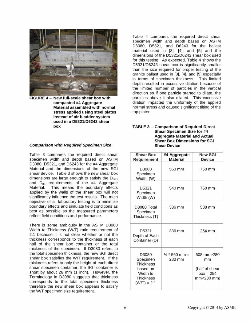
FIGURE 4 – New full-scale shear box with
compacted #4 Aggregate Material assembled with normal stress applied using steel plates instead of air bladder system used in a D5321/D6243 shear box
Comparison with Required Specimen Size Table 3 compares the required direct shear specimen width and depth based on ASTM D3080, D5321, and D6243 for the #4 Aggregate Material and the dimensions of the new SGI shear device. Table 3 shows the new shear box dimensions are large enough to satisfy the Dmax and D85 requirements of the #4 Aggregate Material. This means the boundary effects applied by the walls of the shear box will not significantly influence the test results. The main objective of all laboratory testing is to minimize boundary effects and simulate field conditions as best as possible so the measured parameters reflect field conditions and performance. There is some ambiguity in the ASTM D3080 Width to Thickness (W/T) ratio requirement of 2:1 because it is not clear whether or not the thickness corresponds to the thickness of each half of the shear box container or the total thickness of the specimen. If D3080 refers to the total specimen thickness, the new SGI direct shear box satisfies the W/T requirement. If the thickness refers to only the height of each direct shear specimen container, the SGI container is short by about 26 mm (1 inch). However, the Terminology in D3080 suggests that thickness corresponds to the total specimen thickness therefore the new shear box appears to satisfy the W/T specimen size requirement.
Table 4 compares the required direct shear specimen width and depth based on ASTM D3080, D5321, and D6243 for the ballast material used in [3], [4], and [5] and the dimensions of the D5321/D6243 shear box used for this testing. As expected, Table 4 shows the D5321/D6243 shear box is significantly smaller than the size required for proper testing of the granite ballast used in [3], [4], and [5] especially in terms of specimen thickness. This limited depth resulted in excessive dilation because of the limited number of particles in the vertical direction so if one particle started to dilate, the particles above it also dilated. This excessive dilation impacted the uniformity of the applied normal stress and caused significant tilting of the top platen. TABLE 3 – Comparison of Required Direct
Shear Specimen Size for #4 Aggregate Material and Actual Shear Box Dimensions for SGI Shear Device
Shear Box
Requirement #4 Aggregate
Material New SGI Device
D3080
Specimen Width (W)
560 mm
760 mm
D5321
Specimen Width (W)
540 mm
760 mm
D3080 Total Specimen
Thickness (T)
336 mm
508 mm
D5321
Depth of Each Container (D)
336 mm
254 mm
D3080
Specimen Thickness based on Width to
Thickness (W/T) = 2:1
½ * 560 mm =
280 mm
508 mm>280
mm
(half of shear box = 254
mm<280 mm)
6 Copyright © 2014 by ASME

Using the SGI shear box, the shear strength and deformation characteristics of the #4 Aggregate material were investigated to characterize the behavior of a granite based ballast. The resulting shear strength properties differ from previously reported values, e.g., no cohesion intercept, because the boundary effects are minimized due to the unprecedented specimen size (about 1 m wide and 0.6 m deep). Smaller specimen sizes, e.g., 0.3 m wide and 0.2 m deep, result in significant confinement of the ballast particles which results in measurement of a large cohesion intercept even though ballast is a coarse-grained or cohesionless material. TABLE 4 – Comparison of Required Direct
Shear Specimen Size in [4] and Actual Shear Box Dimensions for D5321/D6243 Device
Shear Box
Requirement Huang et al. [4] Ballast
D5321/D6243 Device
D3080
Specimen Width (W)
630 mm
760 mm
D5321
Specimen Width (W)
795 mm
760 mm
D3080 Total Specimen
Thickness (T)
378 mm
228 mm
D5321
Depth of Each Container (D)
378 mm
114 mm
D3080
Specimen Thickness based on Width to
Thickness (W/T) = 2:1
½ * 630 mm =
315 mm
228 mm<315
mm
(upper half of shear box =
114 mm<<315 mm)
Minimizing the boundary effects in a direct shear test also allows a better correlation between ballast strength and field track support for different levels of particle degradation, fouling, and inclusion of geosynthetics. TYPICAL TEST RESULTS Figure 5 presents typical shear stress-displacement relationships obtained using the full-scale SGI shear box and the #4 Aggregate Material. The #4 Aggregate Material was tested using effective normal stresses (σ’n) of 3.7, 11.4, and 19.2 kPa to simulate typical ballast thicknesses of 0.3 to 0.6 m (1 to 2 ft). A shear displacement rate of 1 mm/min (0.04 in/min) was used for the full-scale shear box testing herein. The shear stress-displacement relationships indicate a peak shear stress is mobilized in each test and the post-peak behavior varies during the test due to the interaction between the large angular ballast particles.
FIGURE 5 – Typical test results using new
full-scale shear box with compacted #4 Aggregate Material and effective normal stresses (σ’n) of 3.7, 11.4, and 19.2 kPa
For comparison purposes, Figure 6 presents typical shear stress-displacement relationships reported in [5] using the D5321/D6243 shear box. The granite ballast was tested using much higher initial effective normal stresses of 103, 173, and 242 kPa. These normal stresses also varied throughout the test due to significant specimen dilation which caused tilting of the top
σ’n =19.2 kPa
σ’n =11.4 kPa
σ’n =3.7 kPa
7 Copyright © 2014 by ASME

platen and the inherent non-uniform stress conditions applied by a air bladder system. A fast shear displacement rate of 12 mm/min (0.47 in/min) also was used in [5] for the D5321/D6243 shear box testing. The shear stress-displacement relationships in Figure 6 show displacement hardening behavior which is probably due to significant boundary, dilation, and/or non-uniform normal stress effects in the small shear box. In addition, there is substantial variation in the shear stress measurements with increasing shear displacement as the large ballast particles are trying to adjust and rearrange in the small shear box. Figure 7 presents the peak and large displacement failure envelopes obtained from the shear stress-displacement relationships shown in Figure 5 for the #4 Aggregate Material tested in the full-scale SGI shear box. The peak and large displacement failure envelopes correspond to reasonable values of effective stress friction angle, i.e., 51 and 48 degrees, respectively, for a coarse and angular unbound aggregate material. More importantly, the test results in Figure 7 indicate no cohesion intercept, which is expected for coarse aggregate in the field, i.e., no boundary effects.
FIGURE 6 – Direct shear test results
presented using D5321/D6243 shear box and granite ballast in [5] and initial effective normal stresses (σ’n) of 103, 173, and 242 kPa
For comparison purposes, Figure 8 presents the peak shear stresses and failure envelopes obtained from D5321/D6243 direct shear testing summarized in [3], [4], and [5]. The peak failure envelopes correspond to somewhat low values of effective stress friction angle, i.e., 41 to 47 degrees, for a coarse and angular aggregate material. More importantly, the peak failure envelopes for the D5321/D6243 shear box show a substantial cohesion intercept, which is not expected for coarse unbound aggregate. This substantial cohesion (~100 kPa or ~2100 psf) is indicative of boundary effects that provide an artificial confinement to the large aggregate particles at no confining pressure.
FIGURE 7 – Failure envelope obtained for #4 Aggregate Material tested in SGI full-scale shear box
Another difference between the D5321/D6243 direct shear testing and the testing herein is the large normal stresses used in the previous work by [3], [4], and [5]. The normal stresses used herein reflect the field conditions in which 0.3 to 0.6 m (1 to 2 ft) of ballast is present. The high normal stresses used in [3], [4], and [5] were probably applied to reduce the dilation and tilting of the top platen that occurred in the tests.
σ’n =242 kPa
σ’n =173 kPa
σ’n =103 kPa
8 Copyright © 2014 by ASME

FIGURE 8 – Comparison of failure envelopes
obtained using SGI full-scale shear box and D5321/D6243 shear box by [4] and [5]
FUTURE TESTING With the development of the full-scale shear box for ballast testing now complete, the following four areas of future testing are being pursued: • Additional full-scale direct shear testing of
various types of ballast to investigate the effect ballast type on shear strength and compressibility.
• Perform seismic wave testing [9] to determine modulus of the specimens before shear testing to develop a relationship between density and shear modulus. This relationship is desired because density is needed to convert shear wave velocity from seismic wave testing to shear modulus using Equation (1).
2* sG Vρ= (1)
where: G = shear modulus Vs = shear wave velocity ρ = material density
• Investigate the effects of ballast fouling on
shear strength and compressibility with natural and coal materials.
• Interface shear behavior between
ballast and various geosynthetics, such as, geogrids, geocells, and geotextiles.
SUMMARY A full-scale direct shear box was developed and used herein to measure the shear strength of a granite ballast material. To satisfy ASTM D3080, D5321, and D6243 test method requirements, a direct shear box that could accommodate an approximately 1 m (3 feet) wide and 0.6 m (2 feet) deep specimen was developed. This shear box is much larger than current shear boxes being used for ballast testing. The shear strength parameters for the clean and angular granite ballast tested herein under typical as-placed conditions and effective normal stresses representative of railroad track conditions are a cohesion intercept of zero and a friction angle of about 50 degrees. The zero cohesion is in agreement with coarse unbound aggregate material and indicates the specimen size is sufficient to minimize boundary effects. The key specimen size requirements in ASTM D3080, D5321, and D6243 are listed in Table 1 and include a specimen width being greater than or equal to 10 times Dmax and 15 times D85. With typical values of Dmax for ballast being greater than 50 mm (2 inches), a full-scale shear box is required. In the new shear box, the normal stress is applied via dead weights to transmit a uniform normal stress across the specimen including the 90 degree corners of the shear box. A dead weight was selected over an air bladder system which is typically used in a D5321/D6243 shear box because the air bladder system does not apply a uniform normal stress, especially in the corners, and the large specimen area would be difficult to adequately cover with an air bladder. Finally, future testing with the full-scale shear box is investigating the effect(s) of ballast fouling, various geosynthetic interfaces, and
9 Copyright © 2014 by ASME

types of ballast on shear strength, compressibility, and stiffness properties. In particular, a correlation between initial density and shear wave velocity is being developed to facilitate interpretation of field seismic wave testing being used to assess track substructure performance [9]. REFERENCES [1] Chiang, C. C. (1989). Effects of Water
and Fines on Ballast Performance in Box Tests. Master of Science Degree Project Report No. AAR89-366P, University of Massachusetts, 1989.
[2] Han, X. and Selig, E. T. (1997). “Effects
of Fouling on Ballast Settlement.” Proc., 6th International Heavy Haul Railway Conference, Cape Town, South Africa, 1997.
[3] Huang, H., Dombrow, W., and
Tutumluer, E. (2009). "Laboratory Characterization of Fouled Railroad Ballast Behavior." Manuscript 09-2065, CD-ROM Proceedings of 88th Transportation Research Board Meeting or Transportation Research Record 2117, http://trb.metapress.com/content/v036008114058630/, pp. 93-101.
[4] Dombrow, W., Huang, H., and
Tutumluer, E. (2009). “Comparison of coal dust fouled railroad ballast behavior – granite vs. limestone.” Proceedings of 8th International Conferecne on Bearing Capacity of Roads and Airfields, Volume 2, pages 1349-1360; https://getinfo.de/app/Comparison-of-coal-dust-fouled-railroad-ballast/id/BLCP%3ACN076823120.
[5] Boler, H. (2012). “On the shear strength
of polyurethane coated railroad ballast.” Thesis submitted for partial fullfillment of Master of Science Degree requirements, University of Illinois at Urbana Champaign, 81 p.
[6] ASTM (2011). “D3080/D3080M:
Standard Test Method for Direct Shear Test of Soils under Consolidated
Drained Conditions.” American Society for Testing and Materials International, West Conshohocken, Pennsylvania, Vol. 04.08.
[7] ASTM (2013). “D5321/D5321M:
Standard Test Method for Determining the Shear Strength of Soil-Geosynthetic and Geosynthetic-Geosynthetic Interfaces by Direct Shear Method.” American Society for Testing and Materials International, West Conshohocken, Pennsylvania, Vol. 04.13.
[8] ASTM (2013). “D6243/D6243M:
Standard Test Method for Determining the Internal and Interface Shear Strength of Geosynthetic Clay Liner by the Direct Shear Method.” American Society for Testing and Materials International, West Conshohocken, Pennsylvania, Vol. 04.13.
[9] Stark, T.D., Nazarian, S., Ho, C.L., and
Tutumluer, E., “Seismic Testing for Track Substructure (Ballast and Subgrade) Assessment for Passenger/Freight Corridors”. Proceedings of the ASME 2013 Joint Rail Conference (JRC2013), Knoxville, TN, April, 2013.
10 Copyright © 2014 by ASME