ballasts - helvar · height 'c' (mm) 21 21 'd' (mm) 350 420 t07 111 1g...
TRANSCRIPT

Ballasts

3Egge
r © C
hris
tian
Vorh
ofer
4-17
18-3
334
-53
54-6
8
Helvar is an international lighting technologies company specialised in energy efficient components and solutions for lighting and lighting control systems. Helvar is a family-owned company established in 1921.
In addition to luminaire manufacturers, our customer base comprises electrical and lighting designers and electrical contractors. Our wide understanding of both components and lighting systems enables us to design versatile and energy efficient lighting solutions.
We serve our customers locally in over 40 countries. Our headquarters are located in Finland, as are our component product development and manufacturing operations. Our lighting control competence centre is in England. Worldwide, our customers are served by offices in eight countries and our global network of partners.
HELVAR
CONTROLLABLE ELECTRONIC BALLASTS
STANDARD ELECTRONIC BALLASTS
MAGNETIC BALLASTS
GENERAL INFORMATION
DALI & 1-10 V controllable ballasts
For fluorescent & HID lamps
Instructions for use, Lamp ballast compatibility

4 Helvar | Data is subject to change without notice. More information at: www.helvar.com
Helvar have a comprehensive range of controllable ballasts covering both analogue solutions (1-10 VDC) and solutions with DALI interfaces. All ballasts are microprosessor controlled utilizing the latest technology highlighting energy saving, quality and lighting comfort.
Helvar controllable ballasts have superior features such as:• OCC technology: highest possible EEI=A1BAT• Very low stand-by power• Multi-load operations in several compact and T5 lamps• Single/twin operation in one iDim-c ballast• In building management systems the DALI ballasts can
provide information of the energy consumption, running hours et.c. on-line and directly from the luminaire
EL-iDim / EL-iDim-c DALI BALLASTS
EL-iDim / EL-iDim-c DALI ballasts are designed for a broad range of applications from the smallest intelligent luminaires to major lighting installations in large building complexes. What’s more, they offer the important advantage of enabling everything to be achieved with the same ballasts. EL-iDim / EL-iDim-c DALI ballasts are also fully compatible
CONTROLLABLE ELECTRONIC BALLASTS
with Helvar iDim sensors, the combination creating the latest high-tech innovation available to the lighting market. With out-of-box functionality, the Helvar system is moreover, easy to install and use, and maintenance costs are always kept to a minimum.
EL-sc 1-10 V BALLASTS
The fully electronic, microprocessor-controlled EL-sc ballasts offer significant performance advantages over other solutions, especially with regard to energy efficiency, lighting quality and comfort.In addition, the EL-sc range has a multi-control feature allowing for dimming either by an analogue 1-10 VDC signal or by a contact closure (Switch-Control). This dimming method is unique in that both control methods can be used simultaneously, offering a high degree of flexibility in lighting design.

5Helvar | Data is subject to change without notice. More information at: www.helvar.com
OCCTM - OPTIMUM CATHODE CONTROLThe proven OCCTM - Optimum Cathode Control technology used in Helvar EL-s, EL-sc, EL-iDim and EL-TCs electronic ballast ranges. OCCTM ensures that the electrical parameters supplied to the lamp are always optimum, minimising system losses and maximising lamp lifetime. The achieved energy saving is considerable compared to existing ballasts on the market.

6
EL-iDim
a
d
d
b
c
A1 BAT
Helvar | Data is subject to change without notice. More information at: www.helvar.com
Digital DALI electronic ballasts for T5 fluorescent lamps
Lamp type
Wattage No. of lamps
Ballast EEI Dimensions Connection Weight Circuit power
Mains current
Lamp power
(p.14) (g) (W) (A) (W)14 1 EL1x14-35iDim A1 BAT 1 1 250 17 0.08-0.07 13.714 2 EL2x14-35iDim A1 BAT 2 2 330 32.5 0.15-0.14 13.714 3 EL3x14iDim A1 BAT 2 3 310 47.5 0.22-0.20 13.714 4 EL4x14iDim A1 BAT 2 4 330 62 0.29-0.27 13.721 1 EL1x14-35iDim A1 BAT 1 1 250 23.5 0.11-0.10 20.721 2 EL2x14-35iDim A1 BAT 2 2 330 46 0.22-0.20 20.724 1 EL1x24iDim A1 BAT 1 1 250 25.5 0.12-0.10 22.524 2 EL2x24iDim A1 BAT 2 2 330 50.5 0.23-0.21 22.528 1 EL1x14-35iDim A1 BAT 1 1 250 32 0.15-0.14 27.828 2 EL2x14-35iDim A1 BAT 2 2 330 62 0.28-0.26 27.8
T5 35 1 EL1x14-35iDim A1 BAT 1 1 250 39 0.18-0.17 34.735 2 EL2x14-35iDim A1 BAT 2 2 330 73.5 0.36-0.30 34.739 1 EL1x39iDim A1 BAT 1 1 250 42.5 0.20-0.18 3839 2 EL2x39iDim A1 BAT 2 2 330 82.5 0.38-0.35 3849 1 EL1x49iDim A1 BAT 1 1 250 55 0.25-0.23 49.349 2 EL2x49iDim A1 BAT 2 2 330 107.5 0.49-0.45 49.354 1 EL1x54iDim A1 BAT 1 1 250 59 0.27-0.25 53.854 2 EL2x54iDim A1 BAT 2 2 330 117 0.53-0.49 53.880 1 EL1x80iDim A1 BAT 1 1 250 86 0.39-0.36 8080 2 EL2x80iDim * A1 BAT 2 2 365 170 0.78-0.70 80
Note: See pages 14-17 for connection diagrams and additional characteristics.* No Switch-Control in EL2x80iDim* *Dimming range 3-100 % for EL3x14iDim & EL4x14iDimFor information on compatibility with amalgam lamps, please contact your local Helvar representative.
• Digital DALI control• Switch-Control *• Stand-by consumption 0.3 W• Dimming range 1-100 % **• Only 21 mm high• Microprocessor controlled• Standard & sidemount possibilities• User friendly, quick release connectors
Delivery informationBallast Unit package Transportation package
Minimum delivery amount
Plastic binding
strip
EUR pallet 1200 x 800
Pallet weight
Pallet height
(pcs.) (kg) (cm)EL1 x iDim 10 980 300 40EL2 x iDim 10 840 325 43EL3 x iDim 10 840 325 43EL4 x iDim 10 840 325 43
T07 111 1G 31.08.2017 1/2Right to use German patent DE19757295 of Tridonic Atco
14-80 W 220-240 V, 50-60 Hz
Dimensions 1 2Length 'a' (mm) 360 430
Width 'b' (mm) 30 30Height 'c' (mm) 21 21
'd' (mm) 350 420

7
EL-iDim
a
d
d
b
c
A1 BAT
Helvar | Data is subject to change without notice. More information at: www.helvar.com
Digital DALI electronic ballasts for T5-eco fluorescent lamps
Lamp type
Wattage No. of lamps
Ballast EEI Dimensions Connection Weight Circuit power 2)
Mains current 2)
Lamp power 2)
(p.14) (g) (W) (A) (W)
T5eco
14 eco 1 EL1x14-35iDim 4) A1 BAT 1 1 250 17 0.08-0.07 13.714 eco 2 EL2x14-35iDim 4) A1 BAT 2 2 330 32.5 0.15-0.14 13.714 eco 3 EL3x14iDim 1) 4) A1 BAT 2 3 310 47.5 0.22-0.20 13.714 eco 4 EL4x14iDim 1) 4) A1 BAT 2 4 330 62 0.29-0.27 13.721 eco 1 EL1x14-35iDim 4) A1 BAT 1 1 250 23.5 0.11-0.10 20.721 eco 2 EL2x14-35iDim 4) A1 BAT 2 2 330 46 0.22-0.20 20.724 eco 1 EL1x24iDim 3) A1 BAT 1 1 250 25.5 0.12-0.10 22.524 eco 2 EL2x24iDim 3) A1 BAT 2 2 330 50.5 0.23-0.21 22.528 eco 1 EL1x14-35iDim 4) A1 BAT 1 1 250 32 0.15-0.14 27.828 eco 2 EL2x14-35iDim 4) A1 BAT 2 2 330 62 0.28-0.26 27.835 eco 1 EL1x14-35iDim 4) A1 BAT 1 1 250 39 0.18-0.17 34.735 eco 2 EL2x14-35iDim 4) A1 BAT 2 2 330 73.5 0.36-0.30 34.749 eco 1 EL1x49iDim 3) A1 BAT 1 1 250 55 0.25-0.23 49.349 eco 2 EL2x49iDim 3) A1 BAT 2 2 330 107.5 0.49-0.45 49.354 eco 1 EL1x54iDim 3) A1 BAT 1 1 250 59 0.27-0.25 53.854 eco 2 EL2x54iDim 3) A1 BAT 2 2 330 117 0.53-0.49 53.880 eco 1 EL1x80iDim 3) A1 BAT 1 1 250 86 0.39-0.36 8080 eco 2 EL2x80iDim 3) * A1 BAT 2 2 365 170 0.78-0.70 80
Note: See pages 14-17 for connection diagrams and additional characteristics.* No Switch-Control in EL2x80iDim1) Dimming range 3-100 % for EL3x14iDim & EL4x14iDim2) Maximum values at 100 % dimming level.3) Power controlled products, no energy saving when ecolamps are used. Lamps are running over powered.4) Current controlled products, maximum 10% energy saving achieved from declared maximum value, depending on lamp types.For information on compatibility with amalgam lamps, please contact your local Helvar representative.
• Digital DALI control• Switch-Control *• Stand-by consumption 0.3 W• Dimming range 1-100 % 1)
• Only 21 mm high• Microprocessor controlled• Standard & sidemount possibilities• User friendly, quick release connectors
Delivery informationBallast Unit package Transportation package
Minimum delivery amount
Plastic binding
strip
EUR pallet 1200 x 800
Pallet weight
Pallet height
(pcs.) (kg) (cm)EL1 x iDim 10 980 300 40EL2 x iDim 10 840 325 43EL3 x iDim 10 840 325 43EL4 x iDim 10 840 325 43
Dimensions 1 2Length 'a' (mm) 360 430
Width 'b' (mm) 30 30Height 'c' (mm) 21 21
'd' (mm) 350 420
T07 111 1G 31.08.2017 2/2Right to use German patent DE19757295 of Tridonic Atco
14-80 W 220-240 V, 50-60 Hz

8
EL-iDim
a
d
d
b
c
A1 BAT
Helvar | Data is subject to change without notice. More information at: www.helvar.com
Digital DALI electronic ballasts for T8 and TC-L fluorescent lamps
Lamp type
Wattage No. of lamps
Ballast EEI Dimensions Connection Weight Circuit power
Mains current
Lamp power
(p.14) (g) (W) (A) (W)
T836 1 EL1x36iDim A1 BAT 1 1 250 35.5 0.17-0.15 32
36 2 EL2x36iDim A1 BAT 2 2 330 70.5 0.32-0.30 32
TC-L
24 1 EL1x24iDim A1 BAT 1 1 250 25.5 0.12-0.10 22.524 2 EL2x24iDim A1 BAT 2 2 330 50.5 0.23-0.21 22.526 1 EL1x14-35iDim 1 A1 BAT 1 1 250 29.3 0.13 2626 2 EL2x14-35iDim 1 A1 BAT 2 2 330 56 0.25 2628 1 EL1x14-35iDim 1 A1 BAT 1 1 250 29.3 0.13 2628 2 EL2x14-35iDim 1 A1 BAT 2 2 330 56 0.25 2636 1 EL1x36iDim A1 BAT 1 1 250 35.5 0.17-0.15 3236 2 EL2x36iDim A1 BAT 2 2 330 70.5 0.32-0.30 3255 1 EL1x55iDim A1 BAT 1 1 250 59.5 0.27-0.25 5555 2 EL2x55iDim A1 BAT 2 2 330 119.5 0.55-0.50 5580 1 EL1x80iDim A1 BAT 1 1 250 86 0.39-0.36 8080 2 EL2x80iDim * A1 BAT 2 2 365 170 0.78-0.70 80
Note: See pages 14-17 for connection diagrams and additional characteristics.* No Switch-Control in EL2x80iDim1) To ensure stable operation of the lamp it is not recommended to dim the light level below 3 %For information on compatibility with amalgam lamps, please contact your local Helvar representative.
• Digital DALI control• Switch-Control *• Stand-by consumption 0.3 W• Dimming range 1-100 %• Only 21 mm high• Microprocessor controlled• Standard & sidemount possibilities• User friendly, quick release connectors
Delivery informationBallast Unit package Transportation package
Minimum delivery amount
Plastic binding
strip
EUR pallet 1200 x 800
Pallet weight
Pallet height
(pcs.) (kg) (cm)EL1 x iDim 10 980 300 40EL2 x iDim 10 840 325 43
Dimensions 1 2Length 'a' (mm) 360 430
Width 'b' (mm) 30 30Height 'c' (mm) 21 21
'd' (mm) 350 420
T07 113 1E 31.08.2017 1/1
Right to use German patent DE19757295 of Tridonic Atco
24 - 80 W 220-240 V, 50-60 Hz

9
EL-iDim-c
A1 BAT
Helvar | Data is subject to change without notice. More information at: www.helvar.com
Digital DALI electronic ballasts for compact fluorescent lamps
Lamp type
Wattage No. of lamps
Ballast EEI Dimensions Connection Weight Circuit power
Mains current
Lamp power
(p.14) (g) (W) (A) (W)
TC-L/TC-F
18 1 EL1/2x18/24iDim-c A1 BAT 123x79x28 5 155 18 0.09 1618 2 EL1/2x18/24iDim-c A1 BAT 123x79x28 6 155 35.5 0.16 1624 1 EL1/2x18/24iDim-c A1 BAT 123x79x28 5 155 26 0.12 2224 2 EL1/2x18/24iDim-c A1 BAT 123x79x28 6 155 50 0.23 22
T5c 22 1 EL1/2x18/24iDim-c A1 BAT 123x79x28 5 155 26 0.12 2240 1 EL1/2x18/24iDim-c A1 BAT 123x79x28 5 155 44.5 0.20 40
TC-DE/TC-TE
18 1 EL1/2x18iDim-c A1 BAT 123x79x28 5 155 20 0.09 16.518 2 EL1/2x18iDim-c A1 BAT 123x79x28 6 155 38 0.17 16.526 1 EL1/2x26-42iDim-c A1 BAT 123x79x28 5 155 28 0.13 2326 2 EL1/2x26-42iDim-c A1 BAT 123x79x28 6 155 56 0.25 23.526 2 EL2x26-42iDim-c A1 BAT 123x79x28 7 176 56 0.25 2532 1 EL1/2x26-42iDim-c A1 BAT 123x79x28 5 155 35 0.16 3132 2 EL2x26-42iDim-c A1 BAT 123x79x28 7 176 70.5 0.32 3242 1 EL1/2x26-42iDim-c A1 BAT 123x79x28 5 155 46 0.2 41.542 2 EL2x26-42iDim-c A1 BAT 123x79x28 7 176 93 0.42 4357 1 EL1/2x26-42iDim-c 1)2) A1 BAT 123x79x28 5 155 61 0.27 56
Note: See pages 14-17 for connection diagrams and additional characteristics.1) Tested and recommended by Helvar, not ENEC approved2) UIN > 220 V, Ta > 18 °CFor information on compatibility with amalgam lamps, please contact your local Helvar representative.
• Digital DALI control• Switch-Control• Stand-by consumption 0.3 W • Dimming range 3-100 %• Multilamp operation• Single and twin lamp operation
Delivery informationBallast Unit package Transportation package
Minimum delivery amount
Carton Box
Pallet 820 x 1280
Pallet weight
Pallet height
(pcs.) (kg) (cm)EL-iDim-c 10 40 800 148 48
T07 120 1G 19.02.2014 1/1
Right to use German patent DE19757295 of Tridonic Atco
Dimensions Length 'a' (mm) 123.0
Width 'b' (mm) 79.0Height 'c' (mm) 28.0
'd' (mm) 100.5 ‘e’ (mm) 65.0 ‘f’ (mm) 111.0
‘g’ (mm) 25.5
18 - 42 W 220-240 V, 50-60 Hz

10
EL-sc
a
d
d
b
c
A1
Helvar | Data is subject to change without notice. More information at: www.helvar.com
Controllable (1-10 V) electronic ballasts for T5 fluorescent lamps
Lamp type
Wattage No. of lamps
Ballast EEI Dimensions Connection Weight Circuit power
Mains current
Lamp power
(p.14) (g) (W) (A) (W)
T5
14 1 EL1x14sc A1 1 8 270 17 0.08-0.07 13.714 2 EL2x14sc A1 2 9 340 31 0.15-0.14 13.714 4 EL4x14sc 2) A1 2 10 340 62 0.29-0.27 13.721 1 EL1x21sc A1 1 8 270 24 0.11-0.10 20.721 2 EL2x21sc A1 2 9 340 46 0.22-0.20 20.724 1 EL1x24sc A1 1 8 270 26 0.13-0.12 22.524 2 EL2x24sc A1 2 9 340 50 0.24-0.20 22.528 1 EL1x28sc A1 1 8 270 31 0.15-0.14 27.828 2 EL2x28sc A1 2 9 340 64 0.30-0.28 27.835 1 EL1x35sc A1 1 8 270 39 0.18-0.17 34.735 2 EL2x35sc A1 2 9 340 78 0.36-0.34 34.739 1 EL1x39sc A1 1 8 270 42 0.20-0.18 3839 2 EL2x39sc A1 2 9 340 83 0.40-0.36 3849 1 EL1x49sc A1 1 8 270 55 0.25-0.23 49.349 2 EL2x49sc A1 2 9 340 106 0.50-0.46 49.354 1 EL1x54sc A1 1 8 270 61 0.28-0.26 53.854 2 EL2x54sc A1 2 9 340 118 0.53-0.49 53.880 1 EL1x80sc A1 1 8 270 88 0.41-0.38 80
Note: See pages 14-17 for connection diagrams and additional characteristics.1) Simultaneous lighting control by Switch-Control and Analogue control2) Dimming range 3-100 % for EL 4x14sc For information on compatibility with amalgam lamps, please contact your local Helvar representative.
• Switch-Control / Analogue control 1)
• Only 21 mm high • Standard & sidemount possibilities• Dimming range 1-100 % 2) • Microprocessor controlled• User friendly, quick release connectors• Low energy consumption• Stabilised, flickerfree light output
Delivery informationBallast Unit package Transportation package
Minimum delivery amount
Plastic binding
strip
EUR pallet 1200 x 800
Pallet weight
Pallet height
(pcs.) (kg) (cm)EL1 x sc 10 980 300 40EL2 x sc 10 840 325 43EL4 x sc 10 840 325 43
Dimensions 1 2Length 'a' (mm) 360 430
Width 'b' (mm) 30 30Height 'c' (mm) 21 21
'd' (mm) 350 420
T07 107 1E 19.02.2014 1/2
14-80 W 220-240 V, 50-60 Hz

11
EL-sc
a
d
d
b
c
A1
Helvar | Data is subject to change without notice. More information at: www.helvar.com
Controllable (1-10 V) electronic ballasts for T5-eco fluorescent lamps
Note: See pages 14-17 for connection diagrams and additional characteristics.1) Simultaneous lighting control by Switch-Control and Analogue control2) Dimming range 3-100 % for EL 4x14sc3) Powercontrolled products, no energy saving when ecolamps are used. Lamps are running over powered.For information on compatibility with amalgam lamps, please contact your local Helvar representative.
• Switch-Control / Analogue control 1)
• Only 21 mm high • Standard & sidemount possibilities• Dimming range 1-100 % 2) • Microprocessor controlled• User friendly, quick release connectors• Low energy consumption• Stabilised, flickerfree light output
Delivery informationBallast Unit package Transportation package
Minimum delivery amount
Plastic binding
strip
EUR pallet 1200 x 800
Pallet weight
Pallet height
(pcs.) (kg) (cm)EL1 x sc 10 980 300 40EL2 x sc 10 840 325 43EL4 x sc 10 840 325 43
Dimensions 1 2Length 'a' (mm) 360 430
Width 'b' (mm) 30 30Height 'c' (mm) 21 21
'd' (mm) 350 420
T07 107 1E 19.02.2014 2/2
Lamp type
Wattage No. of lamps
Ballast EEI Dimensions Connection Weight Circuit power
Mains current
Lamp power 3)
(p.14) (g) (W) (A) (W)
T5eco
14 eco 1 EL1x14sc A1 1 8 270 17 0.08-0.07 13.714 eco 2 EL2x14sc A1 2 9 340 31 0.15-0.14 13.714 eco 4 EL4x14sc 2) A1 2 10 340 62 0.29-0.27 13.721 eco 1 EL1x21sc A1 1 8 270 24 0.11-0.10 20.721 eco 2 EL2x21sc A1 2 9 340 46 0.22-0.20 20.724 eco 1 EL1x24sc A1 1 8 270 26 0.13-0.12 22.524 eco 2 EL2x24sc A1 2 9 340 50 0.24-0.20 22.528 eco 1 EL1x28sc A1 1 8 270 31 0.15-0.14 27.828 eco 2 EL2x28sc A1 2 9 340 64 0.30-0.28 27.835 eco 1 EL1x35sc A1 1 8 270 39 0.18-0.17 34.735 eco 2 EL2x35sc A1 2 9 340 78 0.36-0.34 34.749 eco 1 EL1x49sc A1 1 8 270 55 0.25-0.23 49.349 eco 2 EL2x49sc A1 2 9 340 106 0.50-0.46 49.354 eco 1 EL1x54sc A1 1 8 270 61 0.28-0.26 53.854 eco 2 EL2x54sc A1 2 9 340 118 0.53-0.49 53.880 eco 1 EL1x80sc A1 1 8 270 88 0.41-0.38 80
14-80 W 220-240 V, 50-60 Hz

12
EL-sc
a
d
d
b
c
A1
Helvar | Data is subject to change without notice. More information at: www.helvar.com
Controllable (1-10 V) electronic ballasts for T8 fluorescent lamps
Lamp type
Wattage No. of lamps
Ballast EEI Dimensions Connection Weight Circuit power
Mains current
Lamp power
(p.14) (g) (W) (A) (W)
T8
18 1 EL1x18sc A1 1 8 270 19 0.09-0.08 16
18 2 EL2x18sc A1 2 9 340 37 0.18-0.15 16
18 4 EL4x18sc 2) A1 2 10 340 72 0.33-0.30 16
36 1 EL1x36sc A1 1 8 270 37 0.17-0.16 32
36 2 EL2x36sc A1 2 9 340 71 0.33-0.30 32
58 1 EL1x58sc A1 1 8 270 55 0.27-0.26 50
58 2 EL2x58sc A1 2 9 340 108 0.50-0.46 50
70 1 EL1x70sc A1 1 8 270 65 0.31-0.27 60
Note: See pages 14-17 for connection diagrams and additional characteristics.1) Simultaneous lighting control by Switch-Control and Analogue control2) Dimming range 3-100 % for 4x18scFor information on compatibility with amalgam lamps, please contact your local Helvar representative.
• Switch-Control / Analogue control 1)
• Only 21 mm high • Standard & sidemount possibilities• Dimming range 1-100 % 2) • Microprocessor controlled• User friendly, quick release connectors• Low energy consumption• Flickerless light
Dimensions 1 2Length 'a' (mm) 360 430
Width 'b' (mm) 30 30Height 'c' (mm) 21 21
'd' (mm) 350 420
T07 108 1C 19.02.20141/1
18-70 W 220-240 V, 50-60 Hz
Delivery informationBallast Unit package Transportation package
Minimum delivery amount
Plastic binding
strip
EUR pallet 1200 x 800
Pallet weight
Pallet height
(pcs.) (kg) (cm)EL1 x sc 10 980 300 40EL2 x sc 10 840 325 43EL4 x sc 10 840 325 43

13
EL-sc
a
d
d
b
c
A1
Helvar | Data is subject to change without notice. More information at: www.helvar.com
Controllable (1-10 V) electronic ballasts for compact fluorescent lamps
Lamp type
Wattage No. of lamps
Ballast EEI Dimensions Connection Weight Circuit power
Mains current
Lamp power
(p.14) (g) (W) (A) (W)
TC-L
24 1 EL1x24sc 2) A1 1 8 270 26 0.13-0.12 2424 2 EL2x24sc 2) A1 2 9 340 50 0.24-0.20 2436 1 EL1x36sc A1 1 8 270 37 0.17-0.16 3236 2 EL2x36sc A1 2 9 340 71 0.33-0.30 3240 1 EL1x39sc 2) A1 1 8 270 44 0.20-0.18 4040 2 EL2x39sc 2) A1 2 9 340 84 0.40-0.36 4055 1 EL1x55sc A1 1 8 270 61 0.28-0.26 5555 2 EL2x55sc A1 2 9 340 117 0.53-0.49 5580 1 EL1x80sc 2) A1 1 8 270 88 0.41-0.38 80
TC-F24 1 EL1x24sc 2) A1 1 8 270 26 0.13-0.12 2424 2 EL2x24sc 2) A1 2 9 340 50 0.24-0.20 2436 1 EL1x36sc 2) A1 1 8 270 37 0.17-0.16 3236 2 EL2x36sc 2) A1 2 9 340 71 0.33-0.30 32
T5c 40 1 EL1x39sc 2) A1 1 8 270 43 0.20-0.18 40
Note: See pages 14-17 for connection diagrams and additional characteristics.1) Simultaneous lighting control by Switch-Control and Analogue control 2) Tested and recommended by Helvar, not ENEC approved combinationFor information on compatibility with amalgam lamps, please contact your local Helvar representative.
• Switch-Control / Analogue control 1)
• Only 21 mm high • Standard & sidemount possibilities• Dimming range 1-100 % • Microprocessor controlled• User friendly, quick release connectors• Low energy consumption• Flickerless light
Dimensions 1 2Length 'a' (mm) 360 430
Width 'b' (mm) 30 30Height 'c' (mm) 21 21
'd' (mm) 350 420
T07 109 1C 19.02.2014 1/1
24-80 W 220-240 V, 50-60 Hz
Delivery informationBallast Unit package Transportation package
Minimum delivery amount
Plastic binding
strip
EUR pallet 1200 x 800
Pallet weight
Pallet height
(pcs.) (kg) (cm)EL1 x sc 10 980 300 40EL2 x sc 10 840 325 43EL4 x sc 10 840 325 43

14
1
8
5
2
10
6 7
SWITCH-CONTROL
SWITCH-CONTROL
3
9
4
SWITCH-CONTROL
SWITCH-CONTROL
1 EL1x ...iDim2 EL2x ...iDim3 EL3x ...iDim4 EL4x ...iDim5 EL1/2x...iDim-c6 EL1/2x...iDim-c7 EL2x...iDim-c
SWITCH-CONTROL SWITCH-
CONTROLSWITCH-
CONTROL
1 EL1x ...sc2 EL2x ...sc3 EL4x ...sc
Helvar | Data is subject to change without notice. More information at: www.helvar.com
Connection diagramsEL-iDim
EL-sc
T07 114 1G 9.02.2014 1/2
NOTE: All wiring to the connectors marked with a red dot (hot wires) should be as short as possible.
NOTE: All wiring to the connectors marked with a red dot (hot wires) should be as short as possible.
Right to use German patent DE19757295 of Tridonic Atco
1-10 VDC control< 1mA
1-10 VDC control< 1mA
SWITCH-CONTROL*
SWITCH-CONTROL*
1-10 VDC control< 1mA
SWITCH-CONTROL*
* Connection between the Switch-Control input (pin1) and N (or L).

15Helvar | Data is subject to change without notice. More information at: www.helvar.com
Characteristics
Standards
T07 114 1G 9.02.2014 2/2
EL-iDim EL-iDim-c EL-scMax.temperature at tc point 75 °C 3) 75 °C 80 °CAmbient temperature range +10…+50 °C 1) 5) 6) +10…+50 °C 5) +10…+50 °C 1)
Storage temperature range -40…+80 °C -40…+80 °C -40…+80 °CMaximum relative humidity no condensation no condensation no condensationNumber of starts per lamp > 50 000 > 50 000 > 50 000AC Range 198-264 VAC 198-264 VAC 198-264 VAC
DC range (starting voltage >198VDC) 176-280 VDC 176-280 VDC 176-280 VDCOver voltage duration 320 VAC, 1h 320 VAC, 1h 320 VAC, 1 hEBLF (Emergency Ballast Lumen Factor) N/A > 0.5 7) N/ABLF (Ballast Lumen Factor), steady state ~1 ~1 ~1Programmable light output for DC operation yes yes N/APower factor (at maximum), typical 0.96 0.96 0.98Earth leakage current < 0.4 mA < 0.4 mA < 0.4 mAMaximum working voltage (Uout) 400 V 400 V 400 VLifetime (90 % survival) 50 000 h, at tc 50 000 h, at tc 50 000 h, at 70 °C tc
Max length of ballast to lamp wiring 1.5 m / 2 m (hot / cold) 2)4) 1 m / 1 m (hot / cold) 4) 1.5 m/2 m (hot/cold)2)
Max length of DALI control wires 300 m 9) 300 m 9) N/AIgnition time, typical 1.0 s 1.0 s 8) <1.3 sType of starting Preheat (warm start) Preheat (warm start) Preheat (warm start)
1) To ensure stable operation of TC-L lamps in ambient temperatures below 18 OC it is not recommended to dim the light level below 3 %2) For TC-L lamps 1 m / 2 m (hot/cold lamp wires)3) For EL 3x14iDim, tc = 65 OC4) Minimise lamp wire length variations in order to avoid imbalance in light output.5) When using EL3x14iDim, EL4x14iDim and EL1/2x18/24iDim-c ballasts in ambient temperatures below 15 OC it is not recommended to
dim the light level below 10 % to ensure stable lamp operation.6) For EL2x80iDim, it is not recommended to dim the light below 5 % in temperatures below 15 OC7) EL2x26-42iDim-c; EBLF > 0,38) EL1/2x18/24iDim-c ignition time = 1.4 s 9) Maximum allowed voltage drop is 2 V in 250 m wire
* EN 60081 for T5 & T8 fluorescent lamps, EN 60901 for compact fluorescent lamps
EL-iDim EL-iDim-c EL-scGeneral and safety requirements EN61347-2-3Additional safety requirements for AC/DC supplied ballasts acc. to EN61347-2-3 Annex J
N/A
Performance requirements EN60929Preheat starting Lamp life acc. to EN60081 / EN60901 *)
Mains current harmonics, acc. to EN61000-3-2 Radio Frequency Interference, acc. to EN55015Immunity standard, acc.to EN61547Vibration test EN60068-2-64 test FhBump test EN60068-2-29 test EbThermal protection class EN61347, C5eTested and proven compatible with DALI V1 (IEC62386, 2009) N/A

16
A) 0-25 m
B) 25-200 m
1µF
1µF
Helvar | Data is subject to change without notice. More information at: www.helvar.com O07 116 1D 19.02.2014 1/1
Switch-Control Information, EL-iDim / EL-iDim-c ballasts
Switch-Control provides ON/OFF switching and UP/DOWN dimming functionality from one or more simple switches. Switch-Control and DALI can not be connected to the iDim ballast at the same time.
Suitable switch: • Automatic return type• Mains rated Connection:• EL-iDim ballasts: To the DALI input• Wire length: 25 m maximum, diagram A 25 - 200 m, use a capacitor (1 µF, 275 V), diagram B• Ballasts per switch: 50 (observe above)• Ensure all ballasts and associated switches are connected to the
same mains phase
Operation:• Switch off: Short push of the switch ( < 0.4 second)• Switch on: Short push of the switch ( < 0.4 second)• EL-iDim ballasts will switch on to the last set level• Dimming: Long push of the switch ( > 0.5 second)
• If lamps are off, the ballast dims up from minimum• If lamps are on, the ballast dims in the opposite direction to
previously• The first dimming direction is dimming down
Correction of out of sequence operation:• Switch the mains supply off and on, or…• Long push (until all lamps are on), then a short push (all lamps off),
then switch on
Compatibility:Some ballasts manufacturers have functionality similar to Helvar Switch-Control. These methods are NOT COMPATIBLE with each other.
Connection• To the DALI input
Right to use German patent DE19757295 of Tridonic Atco
Power On to last level function from Switch-ControlPower On to last level function recalls the light level after mains break.Power On to last level operation sequence:
Activation• Activation is started with the light switched ON using the following sequence.
• 1 x long switch (20 - 25 s)• 3 x short switch (90 - 360 ms)• 1 x long switch (20 - 25 s)
Between the switches, approximately 2 seconds of delay is allowed.
Deactivation• Deactivation is started with the light switched OFF (standby) using the following sequence.
• 1 x long switch (20 - 25 s)• 3 x short switch (90 - 360 ms)• 1 x long switch (20 - 25 s)
Between the switches, approximately 2 seconds of delay is allowed.

17Helvar | Data is subject to change without notice. More information at: www.helvar.com O07 115 1B 19.02.20141/1
Switch-Control information, EL-sc ballasts
Switch-Control provides ON/OFF switching and UP/DOWN dimming functionality from one or more simple switches. Switch-Control can be used together and simultaneously with other compatible control devices.• EL-sc ballasts and analogue 1-10 V control.
Suitable switch: • Automatic return type. Mains rated (Mains is still present at the
ballast terminals if the lamps are switched off from Switch-Control).• The switch should withstand a short circuit current of: - 0.2 mA per ballast Connection:• Between the Switch-Control input and N (or L).• Wire length: 200 m maximum.• Ballasts per switch: 50 (observe above).• Ensure all ballasts and associated switches are connected to the
same mains phase.
Operation:• Switch off: Short push of the switch (<0.4 second).• Switch on: Short push of the switch (<0.4 second).
• Re-strike within 3 seconds of switch off is prevented to ensure optimal lamp warm start.
• EL-sc ballasts will switch on to the analogue control set level, both when switching ON from the switch or from the mains supply.
• Dimming: Long push of the switch (>0.5 second).• If lamps are off, the ballast dims up from minimum.• If lamps are on, the ballast dims in the opposite direction to
previously.• The first dimming direction is dimming up.
Regaining analogue control when Switch-Control is active:• Dim the analogue control device from min. to max. and back to
minimum within 1 second.
Correction of out of sequence operation:• Switch the mains supply off and on, or…• Long push (until all lamps are on), then a short push (all lamps off),
then wait 3 seconds and switch on (short push).
Compatibility:Some ballasts manufacturers have functionality similar to Helvar Switch-Control. In most cases these methods are NOT COMPATIBLE with each other.
ConnectionBetween the Switch-Control input (pin1) and L (or N).

18 Helvar | Data is subject to change without notice. More information at: www.helvar.com
Continuous research and development in new technologies has led to the introduction of a host of innovative products over the years. Among the latest of these are the EL-ngn5 standard electronic ballasts with the nominal lifetime up to 100 000 hours at Ta 50 with 90 % survival.
These ballasts are characterized by excellent thermal design, resulting in the highest energy savings and highest reliability, and embodying Helvar’s ‘green values’ that help to guarantee minimum environmental impact!
Helvar uses only the highest-quality components and materials in the manufacture of its ballasts, and combines this with quality design and extensive testing under the harshest conditions. It’s hardly surprising then that failure rates are among the lowest in the market, exceeding industrial expectations 10-fold!
Helvar’s manufacturing processes are also certified to ISO 9001 and ISO14001.
EL-ngn5 – SETTING NEW STANDARDSHelvar has once again set a new standard for T5 high performance electronic ballasts with EL-ngn5 range. Its single lamp versions up to 54 W has a length of only 190 mm with a height of 21 mm. This offers a great possibilities for luminaire designers in designing sleek T5 luminaires without compromises.
Excellent EMC performance make them suitable for use in protection class II fittings. Moreover, its multi-lamp operation feature enables one ballast to drive all HE-T5 lamps in an installation. It is also possible to drive a combination of T5/TC-L lamps with one ballast. This offers major advantages in reduced logistics and transportation costs, as well as contributing to reduced CO2 emissions.
Standard electronic ballasts – highest energy savings and reliability

19Helvar | Data is subject to change without notice. More information at: www.helvar.com
EL-es – THE ECO SAVERThe EL-es is a electronic ballast range for high-volume T8 markets from Helvar. It is developed to meet the needs of luminaire designers looking to replace magnetic ballasts with an electronic version combining the benefits of both!
The EL-es is available for T8 lamps in 2- and 4-lamp configurations.
EL-ngn – THE NEXT GENERATIONThe EL-ngn is a high specification electronic ballast range for high-volume T8 markets from Helvar. Its no-compromise design offers the highest specifications, and its green credentials are confirmed by the fact that it has the highest Energy Efficiency Index. It is also considered to be one of the most user-friendly ballasts, and its proven reliability means that it is widely accepted by even the most demanding and quality-conscious OEMs.
The EL-ngn is available for T8 lamps in 1-, 2- and 4-lamp configurations.
EL-TCs – THE COOL RUNNEREL-TCs range is capable of driving as many as 50 lamps in various TC-DE, TC-TE, TC-SE, TC-DD, T5c, TC-L, TC-F, PL-R, T8 and T5 lamp combinations! The beauty of the ballasts is their ‘dual-technology’ that cost-effectively combines both single- and twin- lamp versions into one ballast.
What’s more, the EL-TCs is surprisingly small, yet it is still capable of running cool even under full thermal stress, thanks to its OCC technology and the clever thermal design of its PCB. This feature has been praised by many OEMs and it is widely acknowledged to be the most reliable CFL ballast in the market.

20
EL-ngn5
a
d
d
b
c
A2 BAT
Helvar | Data is subject to change without notice. More information at: www.helvar.com
Electronic ballasts for T5 fluorescent lamps
Lamp type
Wattage No. of lamps
Ballast EEI Dimensions Connection Weight Circuit power
Mains current
Lamp power
(p.30) (g) (W) (A) (W)
T5
14 1 EL1x14-35ngn5 A2 BAT 1 1 127 15.5 0.08-0.06 13.714 2 EL2x14-35ngn5 A2 BAT 2 12 204 31 0.16-0.15 13.714 3 EL3/4x14ngn5 A2 2 6 204 46 0.22-0.19 13.714 4 EL3/4x14ngn5 A2 2 7 204 62 0.29-0.26 13.714 4 EL4x14ngn5 A2 BAT 2 7 190 63 0.30-0.26 13.721 1 EL1x14-35ngn5 A2 BAT 1 1 127 23 0.12-0.10 20.721 2 EL2x14-35ngn5 A2 BAT 2 12 204 45 0.22-0.19 20.724 1 EL1x24ngn5 A2 1 1 130 25 0.12-0.11 22.524 2 EL2x24ngn5 A2 BAT 2 8 193 49 0.24-0.21 22.524 3 EL3/4x24ngn5 A2 BAT 2 6 208 73 0.34-0.30 22.524 4 EL3/4x24ngn5 A2 BAT 2 7 208 97 0.44-0.40 22.528 1 EL1x14-35ngn5 A2 BAT 1 1 127 30 0.15-0.12 27.828 2 EL2x14-35ngn5 A2 BAT 2 12 204 60 0.29-0.25 27.835 1 EL1x14-35ngn5 A2 BAT 1 1 127 38 0.18-0.16 34.735 2 EL2x14-35ngn5 A2 BAT 2 12 204 75 0.35-0.31 34.739 1 EL1x39/36ngn5 A2 BAT 1 1 130 42 0.19-0.18 3839 2 EL2x39/36ngn5 A2 BAT 2 8 195 81 0.36-0.32 3849 1 EL1x49ngn5 A2 BAT 1 1 130 55 0.25-0.23 49.349 2 EL2x49ngn5 A2 BAT 2 12 211 105 0.50-0.45 49.349 2 EL2x49ngn5-XL A2 BAT 3 12 265 105 0.50-0.45 49.354 1 EL1x54ngn5 A2 BAT 1 1 130 58 0.26-0.24 53.854 2 EL2x54ngn5 A2 BAT 2 8 206 115 0.53-0.48 53.854 2 EL2x54ngn5-XL A2 BAT 3 8 260 115 0.53-0.48 53.880 1 EL1x80ngn5 A2 BAT 2 1 192 86 0.42-0.36 8080 2 EL2x80ngn5 A2 BAT 3 12 300 170 0.80-0.73 80
Note: See pages 30-33 for connection diagrams and additional characteristics.
• Smallest available quality ballast• Standard & sidemount possibilities • Optimal lamp operation• Low power losses• Long lifetime• Green values• High power factor
T07 127 1C 18.01.2016 1/2
Dimensions 1 2 3Lenght 'a' (mm) 190 280 360
Width 'b' (mm) 30 30 30Height 'c' (mm) 21 21 21
'd' (mm) 180 270 350
Delivery informationBallast Unit package Transportation package
Minimum delivery amount
Plastic binding
strip
One-way pallet 1200 x 820
Pallet weight
Pallet height
(pcs.) (kg) (cm)EL1 x ngn5 10 2000 260-300 48EL2 x ngn5 & EL3/4 x ngn5 10 2000 400-450 56EL2x55ngn5 & EL2x80ngn5 10 1500 400-420 56
14-80 W 220-240 V, 50-60 Hz

21
EL-ngn5
a
d
d
b
c
A2 BAT
Helvar | Data is subject to change without notice. More information at: www.helvar.com
Electronic ballasts for T5-eco fluorescent lamps
Lamp type No. of lamps
Ballast EEI Dimensions Connection Weight Circuit power 1)
Mains current 1)
Lamp power 1)
(p.30) (g) (W) (A) (W)
T5eco
14 eco 1 EL1x14-35ngn5 A2 BAT 1 1 127 15.5 0.08-0.06 13.714 eco 2 EL2x14-35ngn5 A2 BAT 2 12 204 31 0.16-0.15 13.714 eco 3 EL3/4x14ngn5 A2 2 6 204 46 0.22-0.19 13.714 eco 4 EL3/4x14ngn5 A2 2 7 204 62 0.29-0.26 13.714 eco 4 EL4x14ngn5 A2 BAT 2 7 190 63 0.30-0.26 13.721 eco 1 EL1x14-35ngn5 A2 BAT 1 1 127 23 0.12-0.10 20.721 eco 2 EL2x14-35ngn5 A2 BAT 2 12 204 45 0.22-0.19 20.724 eco 1 EL1x24ngn5 A2 1 1 130 25 0.12-0.11 22.524 eco 2 EL2x24ngn5 A2 BAT 2 8 193 49 0.24-0.21 22.524 eco 3 EL3/4x24ngn5 A2 BAT 2 6 208 73 0.34-0.30 22.524 eco 4 EL3/4x24ngn5 A2 BAT 2 7 208 97 0.44-0.40 22.528 eco 1 EL1x14-35ngn5 A2 BAT 1 1 127 30 0.15-0.12 27.828 eco 2 EL2x14-35ngn5 A2 BAT 2 12 204 60 0.29-0.25 27.835 eco 1 EL1x14-35ngn5 A2 BAT 1 1 127 38 0.18-0.16 34.735 eco 2 EL2x14-35ngn5 A2 BAT 2 12 204 75 0.35-0.31 34.739 eco 1 EL1x39/36ngn5 A2 BAT 1 1 130 42 0.19-0.18 3839 eco 2 EL2x39/36ngn5 A2 BAT 2 8 195 81 0.36-0.32 3849 eco 1 EL1x49ngn5 A2 BAT 1 1 130 55 0.25-0.23 49.349 eco 2 EL2x49ngn5 A2 BAT 2 12 211 105 0.50-0.45 49.349 eco 2 EL2x49ngn5-XL A2 BAT 3 12 265 105 0.50-0.45 49.354 eco 1 EL1x54ngn5 A2 BAT 1 1 130 58 0.26-0.24 53.854 eco 2 EL2x54ngn5 A2 BAT 2 8 206 115 0.53-0.48 53.854 eco 2 EL2x54ngn5-XL A2 BAT 3 8 260 115 0.53-0.48 53.880 eco 1 EL1x80ngn5 A2 BAT 2 1 192 86 0.42-0.36 8080 eco 2 EL2x80ngn5 A2 BAT 3 12 300 170 0.80-0.73 80
Note: See pages 30-33 for connection diagrams and additional characteristics.1) Maximum 10 % energy saving achieved from declared maximum value depending on difference in lamps from various manufacturers.
• Smallest available quality ballast• Standard & sidemount possibilities • Optimal lamp operation• Low power losses• Long lifetime• Green values• High power factor
T07 127 1C 18.01.2016 2/2
Dimensions 1 2 3Lenght 'a' (mm) 190 280 360
Width 'b' (mm) 30 30 30Height 'c' (mm) 21 21 21
'd' (mm) 180 270 350
Delivery informationBallast Unit package Transportation package
Minimum delivery amount
Plastic binding
strip
One-way pallet 1200 x 820
Pallet weight
Pallet height
(pcs.) (kg) (cm)EL1 x ngn5 10 2000 260-300 48EL2 x ngn5 & EL3/4 x ngn5 10 2000 400-450 56EL2x55ngn5 & EL2x80ngn5 10 1500 400-420 56
14-80 W 220-240 V, 50-60 Hz

22
EL-ngn
a
b
c
a
d
b
c
a
d
d
b
c
a
d
d
b
c
A2 BAT
Helvar | Data is subject to change without notice. More information at: www.helvar.com
Electronic ballasts for T8 fluorescent lamps
Lamp type
Wattage No. of lamps
Ballast EEI Dimensions Connection Weight Circuit power
Mains current
Lamp power
(p.30) (g) (W) (A) (W)
T8
14 1 EL1x15ngn 1) A2 3 1 120 15 0.09-0.07 13
15 1 EL1x15ngn 1) A2 3 1 120 15,5 0.09-0.07 13.5
18 1 EL1x18ngn A2 1 1 190 19 0.09-0.08 16
18 2 EL2x18ngn A2 BAT 1 8 200 37 0.16-0.15 16
18 3 EL3/4x18ngn A2 2 6 210 52 0.25-0.23 16
18 4 EL3/4x18ngn A2 2 7 210 69 0.33-0.30 16
18 4 EL4x18ngn A2 BAT 1 9 200 72 0.33-0.30 16
30 1 EL1x30ngn 1) A2 BAT 3 1 120 26,5 0.14-0.11 24
36 1 EL1x36ngn A2 1 1 191 36 0.16-0.15 32
36 2 EL2x36ngn A2 BAT 1 8 205 71 0.32-0.29 32
58 1 EL1x58ngn A2 1 1 193 55 0.26-0.23 50
58 2 EL2x58ngn A2 BAT 1 8 218 108 0.50-0.45 50
Note: See pages 31-32 for connection diagrams and additional characteristics.
Note: Delivery information for EL1x15ngn and EL1x30ngn as on a page 21 for EL1 x ngn5
1) ENEC and EMC approvals by request.
Delivery informationBallast Unit package Transportation package
Minimum delivery amount
Plastic binding
strip
One-way pallet 1200 x 820
Pallet weight
Pallet height
(pcs.) (kg) (cm)EL1 x ngn 10 1600 330 60EL2 x ngn 10 1600 320-360 60EL3/4x18ngn 10 1500 385 57EL4 x ngn 10 1600 370 60
• Energy saving• Warm Start according to lamp standards• Flickerless light• Covers EMC requirements• Low harmonics• Low power losses• Stabilized output
Dimensions 1 2 3drawing a b c
Length 'a' (mm) 280 280 190Width 'b' (mm) 30 30 30
Height 'c' (mm) 28 21 21 'd' (mm) 270 270 180
T07 104 1F 17.02.2016 1/2
14-58 W 220-240 V, 50-60 Hz

23
EL-s
a
d
d
b
ca
a
d
d
b
cb
A2
Helvar | Data is subject to change without notice. More information at: www.helvar.com
Electronic ballasts for T8 fluorescent lamps
Lamp type
Wattage No. of lamps
Ballast EEI Dimensions Connection Weight Circuit power
Mains current
Lamp power
(p.30) (g) (W) (A) (W)
T858 2 EL2x58s A2 2 2 260 106.5 0.50-0.45 5070 1 EL1x70s A2 13 13 200 64.5 0.30-0.28 6070 2 EL2x70s A2 2 2 260 128 0.59-0.54 60
Note: See pages 31-32 for connection diagrams and additional characteristics.
Delivery informationBallast Unit package Transportation package
Minimum delivery amount
Plastic binding
strip
One-way pallet 1200 x 820
Pallet weight
Pallet height
(pcs.) (kg) (cm)EL1 x s 10 2000 350 - 420 57EL2 x s 10 1500 395 57
• Only 21 mm high • Optimal lamp operation• Wide operational ambient temperature range• Standard & sidemount possibilities• Optional terminals for automatic wiring• Low power losses• Silent operation• Stabilized flickerfree light• High power factor
Dimensions 1 2drawing a a
Length 'a' (mm) 280 360Width 'b' (mm) 30 30
Height 'c' (mm) 21 21 'd' (mm) 270 350
T07 104 1E 19.01.2016 2/2
18-70 W 220-240 V, 50-60 Hz

24
EL-es
aa
d
b
c
A2
Helvar | Data is subject to change without notice. More information at: www.helvar.com
Electronic ballasts for T8 fluorescent lamps
Note: See pages 31-32 for connection diagrams and additional characteristics.
Delivery informationBallast Unit package Transportation package
Minimum delivery amount
Plastic binding
strip
One-way pallet 1200 x 820
Pallet weight
Pallet height
(pcs.) (kg) (cm)EL4x18es 10 1600 330 60EL2x36es 10 1600 330 60EL2x58es 10 1600 350 60
• Energy saver• Stabilized flickerfree light• Approved warm start• High power factor• Silent operation• Good EMC performance
Dimensions 1drawing a
Length 'a' (mm) 280Width 'b' (mm) 30
Height 'c' (mm) 28 'd' (mm) 270
T07 122 1B 19.02.2014
Lamp type
Wattage No. of lamps
Ballast EEI Connection Weight Circuit power Mains current Lamp power
(p.30) (g) (W) (A) (W)
T8
18 4 EL4x18es A2 9 190 72 0.30-0.33 16
36 2 EL2x36es A2 8 190 71 0.32-0.29 32
58 2 EL2x58es A2 8 200 108 0.50-0.45 50
18-58 W 220-240 V, 50-60 Hz

25
A2
EL-ef
da
b
c
Helvar | Data is subject to change without notice. More information at: www.helvar.com
• Efficient and easy lamp replacement • Compact size• Light weight• RoHS compliant
Lamp type
Wattage No. of lamps
Ballast EEI Dimensions Connection Weight Circuit power
Mains current
Lamp power
(p.30) (g) (W) (A) (W)
T8
18 1 EL1x18ef A2 1 3 87 18 0.08-0.09 1518 2 EL2x18ef A2 1 4 91 37 0.15-0.17 1618 4 EL4x18ef A2 2 5 135 70 0.32-0.34 1636 1 EL1x36ef A2 1 3 87 35 0.15-0.17 3236 2 EL2x36ef A2 2 4 128 70 0.32-0.34 3258 1 EL1x58ef A2 1 3 104 53 0.23-0.25 50
Electronic ballasts for T8 fluorescent lamps
18-58 W 220-240 V, 50-60 Hz
Dimensions 1 2Length 'a' (mm) 150 210
Width 'b' (mm) 40 40Height 'c' (mm) 28 30
'd' (mm) 140 200
Delivery informationType Minimum
delivery amount
EUR pallet 1200 x 800
Pallet weight Pallet height
(pcs.) (kg) (cm)EL1x18ef 50 2750 260 98EL2x18ef 50 2750 270 98EL1x36ef 50 2750 260 98EL2x36ef 50 1400 200 86EL1x58ef 50 2750 300 98EL4x18ef 50 1400 210 86
Note: See pages 31-32 for connection diagrams and additional characteristics.
T07 128 1B 15.01.2016

26
EL-ngn5
a
d
d
b
c
A2 BAT
Helvar | Data is subject to change without notice. More information at: www.helvar.com
Electronic ballasts for compact fluorescent lamps
Lamp type
Wattage No. of lamps
Ballast EEI Dimensions Connection Weight Circuit power
Mains current
Lamp power
(p.30) (g) (W) (A) (W)
TC-L
24 1 EL1x24ngn5 A2 1 1 130 25 0.12-0.11 22.524 2 EL2x24ngn5 A2 BAT 2 8 193 49 0.24-0.21 22.524 3 EL3/4x24ngn5 A2 BAT 2 6 208 73 0.34-0.30 22.524 4 EL3/4x24ngn5 A2 BAT 2 7 208 97 0.44-0.40 22.536 1 EL1x39/36ngn5 A2 1 1 130 35 0.16-0.15 3236 2 EL2x39/36ngn5 A2 BAT 2 8 195 69 0.32-0.29 3255 1 EL1x55ngn5 1) A2 BAT 2 1 195 60 0.28-0.24 5555 2 EL2x55ngn5 A2 BAT 3 8 240 118 0.54-0.49 5580 1 EL1x80ngn5 A2 BAT 2 1 192 86 0.42-0.36 8080 2 EL2x80ngn5 A2 BAT 3 13 300 170 0.80-0.73 80
Note: See pages 30-33 for connection diagrams and additional characteristics.1) Also ENEC approved for 55 W T5-C lamps
• Smallest available quality ballast• Standard & sidemount possibilities • Optimal lamp operation• Low power losses• Long lifetime• Green values• High power factor
Delivery informationBallast Unit package Transportation package
Minimum delivery amount
Plastic binding
strip
One-way pallet 1200 x 820
Pallet weight
Pallet height
(pcs.) (kg) (cm)EL1 x ngn5 10 2000 260-300 48EL2 x ngn5 & EL3/4 x ngn5 10 2000 400-450 56EL2x55ngn5 & EL2x80ngn5 10 1500 400-420 56
T07 126 1C 1.3.2017 1/1
Dimensions 1 2 3Lenght 'a' (mm) 190 280 360
Width 'b' (mm) 30 30 30Height 'c' (mm) 21 21 21
'd' (mm) 180 270 350
14-80 W 220-240 V, 50-60 Hz

27
EL-TCs
A2 BAT
Helvar | Data is subject to change without notice. More information at: www.helvar.com
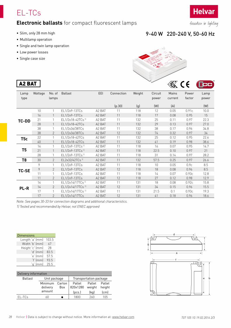
• Slim, only 28 mm high• Multilamp operation• Single and twin lamp operation• Low power losses• Single case size
Lamp type
Wattage No. of lamps
Ballast EEI Connection Weight Circuit power
Mains current
Power factor
Lamp power
(p.30) (g) (W) (A) (W)
TC-L
18 1 EL1/2x18-42TCs A2 BAT 11 132 17 0.08 0.94c 14.818 2 EL1/2x18-42TCs A2 BAT 12 132 32 0.14 0.97 14.824 1 EL1/2x18-42TCs A2 BAT 11 132 26 0.12 0.95 2324 2 EL1/2x18-42TCs A2 BAT 12 132 48 0.21 0.98 22.336 1 EL1/2x36/38TCs A2 BAT 11 132 37 0.17 0.96 3436 1 EL1/2x18-42TCs 1) 2) A2 BAT 12 132 31 0.14 0.96 2836 2 EL1/2x36/38TCs A2 BAT 12 132 72 0.32 0.97 3340 1 EL1/2x18-42TCs 1) A2 BAT 11 132 42 0.19 0.98 39
TC-F
18 1 EL1/2x18-42TCs A2 BAT 11 132 17 0.08 0.94c 14.818 2 EL1/2x18-42TCs A2 BAT 12 132 32 0.14 0.97 14.824 1 EL1/2x18-42TCs A2 BAT 11 132 26 0.12 0.95 2324 2 EL1/2x18-42TCs A2 BAT 12 132 48 0.21 0.98 22.336 1 EL1/2x36/38TCs A2 BAT 11 132 37 0.17 0.96 3436 1 EL1/2x18-42TCs 1)2) A2 BAT 12 132 31 0.14 0.96 2836 2 EL1/2x36/38TCs A2 BAT 12 132 72 0.32 0.97 33
Dimensions Length 'a' (mm) 103.5
Width 'b' (mm) 67Height 'c' (mm) 28
'd' (mm) 83.5 ‘e’ (mm) 57.5 ‘f’ (mm) 93.5
‘g’ (mm) 25.5
T07 105 1G 19.02.2014 1/3
Electronic ballasts for compact fluorescent lamps
Note: See pages 30-33 for connection diagrams and additional characteristics.1) Tested and recommended by Helvar, not ENEC approved2) Light output 93 %
18-40 W 220-240 V, 50-60 Hz
Delivery informationBallast Unit package Transportation package
Minimum delivery amount
Carton Box
Pallet 820x1280
Pallet weight
Pallet height
(pcs.) (kg) (cm)EL-TCs 60 1800 260 105
28
EL-TCs
A2 BAT
Helvar | Data is subject to change without notice. More information at: www.helvar.com
• Slim, only 28 mm high• Multilamp operation• Single and twin lamp operation• Low power losses• Single case size
Lamp type
Wattage No. of lamps
Ballast EEI Connection Weight Circuit power
Mains current
Power factor
Lamp power
(p.30) (g) (W) (A) (W)
TC-DD
10 1 EL1/2x9-13TCs A2 BAT 11 118 12 0.05 0.91c 10.016 1 EL1/2x9-13TCs A2 BAT 11 118 17 0.08 0.95 1521 1 EL1/2x18-42TCs 1) A2 BAT 11 132 25 0.11 0.97 22.328 1 EL1/2x18-42TCs A2 BAT 11 132 29 0.13 0.97 27.038 1 EL1/2x36/38TCs A2 BAT 11 132 38 0.17 0.96 34.838 2 EL1/2x36/38TCs A2 BAT 12 132 74 0.32 0.97 34
T5c 22 1 EL1/2x18-42TCs A2 BAT 11 132 25 0.12 0.95 22.640 1 EL1/2x18-42TCs A2 BAT 11 132 41 0.19 0.98 38.6
T514 1 EL1/2x9-13TCs 1) A2 BAT 11 118 16 0.07 0.95 14.721 1 EL1/2x9-13TCs 1) A2 BAT 11 118 22.5 0.10 0.97 2128 1 EL1/2x9-13TCs 1) A2 BAT 11 118 31 0.14 0.97 28.2
T8 30 2 EL2x32/42TCs 1) A2 BAT 11 132 57.5 0.25 0.97 26.6
TC-SE9 1 EL1/2x9-13TCs A2 BAT 11 118 10 0.05 0.9c 8.59 2 EL1/2x9-13TCs A2 BAT 12 118 18 0.08 0.96 8.511 1 EL1/2x9-13TCs A2 BAT 11 118 14 0.07 0.93c 12.811 2 EL1/2x9-13TCs A2 BAT 12 118 27 0.12 0.98 12.9
PL-R14 1 EL1/2x14/17TCs 1) A2 BAT 11 131 18 0.08 0.92c 15.814 2 EL1/2x14/17TCs 1) A2 BAT 12 131 34 0.15 0.96 15.517 1 EL1/2x14/17TCs 1) A2 BAT 11 131 21.5 0.1 0.93c 19.317 2 EL1/2x14/17TCs A2 BAT 12 131 41 0.18 0.96 18.6
Dimensions Length 'a' (mm) 103.5
Width 'b' (mm) 67Height 'c' (mm) 28
'd' (mm) 83.5 ‘e’ (mm) 57.5 ‘f’ (mm) 93.5
‘g’ (mm) 25.5
T07 105 1G 19.02.2014 2/3
Electronic ballasts for compact fluorescent lamps
Note: See pages 30-33 for connection diagrams and additional characteristics.1) Tested and recommended by Helvar, not ENEC approved
9-40 W 220-240 V, 50-60 Hz
Delivery informationBallast Unit package Transportation package
Minimum delivery amount
Carton Box
Pallet 820x1280
Pallet weight
Pallet height
(pcs.) (kg) (cm)EL-TCs 60 1800 260 105

29
EL-TCs
A2 BAT
Helvar | Data is subject to change without notice. More information at: www.helvar.com
• Slim only 28 mm high• Multilamp operation• Single and twin lamp operation• Low power losses• Single case size
Lamp type
Wattage No. of lamps
Ballast EEI Connection Weight Circuit power
Mains current
Power factor
Lamp power
(p.30) (g) (W) (A) (W)
TC-DE
10 1 EL1/2x9-13TCs A2 BAT 11 118 10 0.05 0.9c 8.910 2 EL1/2x9-13TCs A2 BAT 12 118 20 0.09 0.97 8.913 1 EL1/2x9-13TCs A2 BAT 11 118 15 0.07 0.94c 13.813 2 EL1/2x9-13TCs A2 BAT 12 118 28 0.13 0.98 13.518 1 EL1/2x18TCs A2 BAT 11 120 19 0.09 0.96 16.918 2 EL1/2x18TCs A2 BAT 12 120 36 0.16 0.98 16.926 1 EL1/2x18-42TCs A2 BAT 11 132 27 0.13 0.96 24.726 2 EL1/2x18-42TCs A2 BAT 12 132 51 0.23 0.98 23.826 2 EL2x32/42TCs A2 BAT 12 132 53 0.24 0.97 24
TC-TE
13 1 EL1/2x9-13TCs A2 BAT 11 118 15 0.07 0.94c 13.813 2 EL1/2x9-13TCs A2 BAT 12 118 28 0.13 0.98 13.518 1 EL1/2x18TCs A2 BAT 11 120 19 0.09 0.96 16.918 2 EL1/2x18TCs A2 BAT 12 120 36 0.16 0.98 16.926 1 EL1/2x18-42TCs A2 BAT 11 132 27 0.13 0.96 24.726 2 EL1/2x18-42TCs A2 BAT 12 132 51 0.23 0.98 23.826 2 EL2x32/42TCs A2 BAT 12 132 53 0.24 0.97 2432 1 EL1/2x18-42TCs A2 BAT 11 132 32 0.15 0.97 29.432 2 EL2x32/42TCs A2 BAT 12 132 64 0.29 0.98 28.542 1 EL1/2x18-42TCs A2 BAT 11 132 44 0.2 0.98 42.242 2 EL2x32/42TCs A2 BAT 12 132 85 0.38 0.98 40.557 1 EL1/2x18-42TCs A2 BAT 11 132 58.5 0.26 0.99 54
Delivery informationBallast Unit package Transportation package
Minimum delivery amount
Carton Box
Pallet 820x1280
Pallet weight
Pallet height
(pcs.) (kg) (cm)EL-TCs 60 1800 260 105
Dimensions Length 'a' (mm) 103.5
Width 'b' (mm) 67Height 'c' (mm) 28
'd' (mm) 83.5 ‘e’ (mm) 57.5 ‘f’ (mm) 93.5
‘g’ (mm) 25.5
T07 105 1G 19.02.2014 3/3
Electronic ballasts for compact fluorescent lamps
1) Ballast Lumen Factor for 1x14 W, 2x14 W, 1x17 W: 107 %Note: See pages 30-33 for connection diagrams and additional characteristics.
9-26 W 220-240 V, 50-60 Hz
30
4
7
10 12
5
8
11
6
9
1 2 3
1234
567
8910
123456
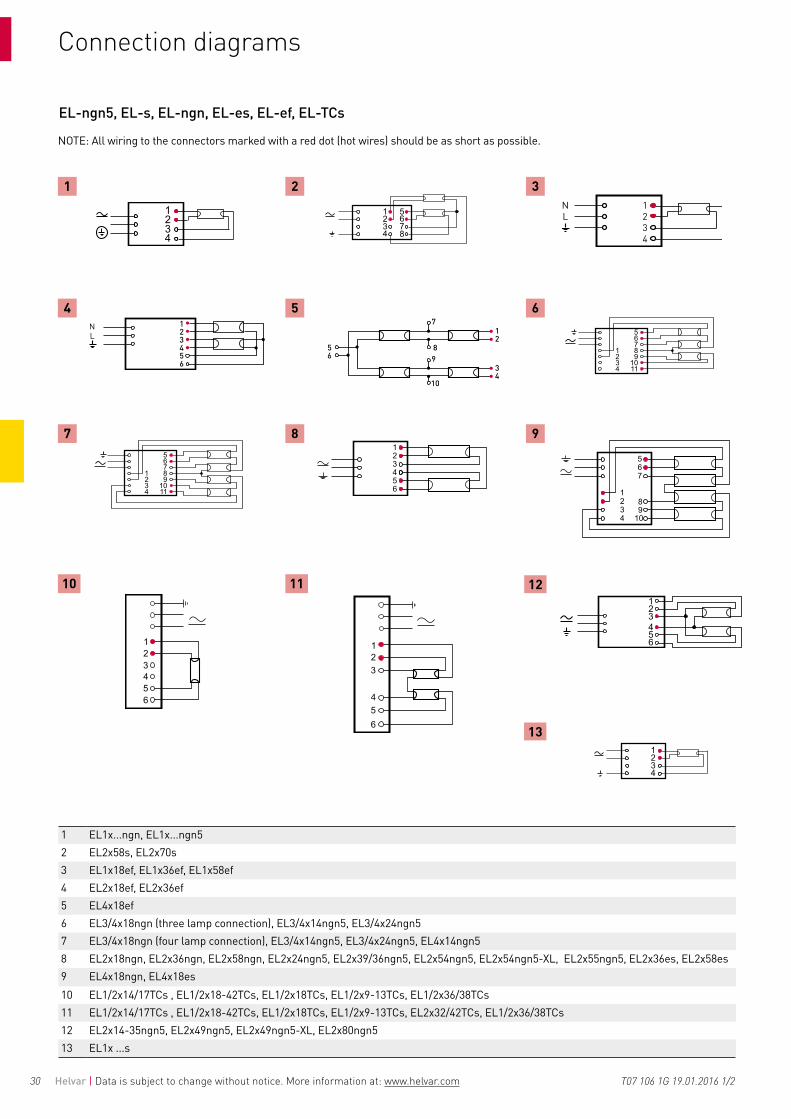
EL-ngn5, EL-s, EL-ngn, EL-es, EL-ef, EL-TCs
123456
NL 1
2
34
56
7
89
10
1234
NL
13
Helvar | Data is subject to change without notice. More information at: www.helvar.com
Connection diagrams
T07 106 1G 19.01.2016 1/2
1 EL1x...ngn, EL1x...ngn52 EL2x58s, EL2x70s3 EL1x18ef, EL1x36ef, EL1x58ef4 EL2x18ef, EL2x36ef5 EL4x18ef6 EL3/4x18ngn (three lamp connection), EL3/4x14ngn5, EL3/4x24ngn57 EL3/4x18ngn (four lamp connection), EL3/4x14ngn5, EL3/4x24ngn5, EL4x14ngn58 EL2x18ngn, EL2x36ngn, EL2x58ngn, EL2x24ngn5, EL2x39/36ngn5, EL2x54ngn5, EL2x54ngn5-XL, EL2x55ngn5, EL2x36es, EL2x58es9 EL4x18ngn, EL4x18es10 EL1/2x14/17TCs , EL1/2x18-42TCs, EL1/2x18TCs, EL1/2x9-13TCs, EL1/2x36/38TCs11 EL1/2x14/17TCs , EL1/2x18-42TCs, EL1/2x18TCs, EL1/2x9-13TCs, EL2x32/42TCs, EL1/2x36/38TCs12 EL2x14-35ngn5, EL2x49ngn5, EL2x49ngn5-XL, EL2x80ngn513 EL1x ...s
NOTE: All wiring to the connectors marked with a red dot (hot wires) should be as short as possible.

31Helvar | Data is subject to change without notice. More information at: www.helvar.com T07 106 1F 19.01.2016 2/2
Characteristics
EL-s EL-ngn EL-ngn5 EL-es EL-TCs EL-efMax.temperature at tc point 75 °C 3) 75 °C 75 °C 7)10) 75 °C 75 °C 70 °CAmbient temperature range -20…+50 °C -20...+50 °C -20...+50 °C 11) -15...+50 °C -20…+50 °C -15...+50 °C Storage temperature range -40…+80 °C -40...+80 °C -40...+80 °C -40...+80 °C -40…+80 °C -40...+80 °C
Maximum relative humidity no condensation
no condensation
no condensation
no condensation
no condensation
no condensation
Number of starts per lamp > 50 000 > 60 000 > 50 000 > 20 000 > 50 000 > 6 000AC Range 198-264 VAC 4) 5) 198-264 VAC 198-264 VAC 198-264 VAC 198-264 VAC 220 - 240 VACDC range (starting voltage >190VDC) 176-280 VDC 5) 176-280 VDC 176-280 VDC 198-264 VDC 9) 176-280 VDC 1) 220 - 240 VDCOver voltage duration 320 VAC, 1 h 320 VAC, 1 h 320 VAC, 1 h 320 VAC, 1 h 320 V / 1 h 270 VAC, 2 hPower factor (at maximum), typical 0.98 0.98 0.98 0.98 > 0.95 0.95Earth leakage current < 0.4 mA < 0.4 mA < 0.4 mA < 0.4 mA < 0.4 mA < 0.4 mAMaximum working voltage (Uout) 400 V 350 V 6) 400 V 6) 350 V 6) 250 V 2) 280 V 12)
Lifetime (90 % survival) 50 000 h, at tc 60 000 h, at tc 60 000 h,8) at tc>100 000h, at Ta 50°C 50 000 h, at tc 50 000 h, at tc 30 000 h, at Tc
45 000 h, at Ta 50°C
Max length of ballast to lamp wiring 2 m 1.5 m 2 m 1.5 m 1 m / 2 m (hot / cold) 2 m
Ignition time, typical ~1.0 s < 1 s ~1 s < 2 s ~1 s 0.3 s
1) For 2 x 42 W lamp, DC range is 190-280 V 2) EL2x32/42TCs 300 V 3) For EL 2x70s, tc = 70 OC4) For EL2x70s AC range is 204-264 V 5) EL2x70s max 6 hours at 176-190 VDC6) 3/4x18ngn, Uout = 400 V
7) 70 °C EL3/4x14ngn58) Please see page 33 for detailed information9) Operationally suitable for emergency use with central battery10) 85 °C, for EL-ngn5-XL-types11) max Ta 65 °C, for EL-ngn5-XL-types12) Uout = 380 V for EL2x36ef & EL4x18ef
StandardsEL-s / EL-su EL-ngn EL-ngn5 EL-es EL-TCs EL-ef
General and safety requirements EN61347-2-3Additional safety requirements for AC/DC supplied ballasts acc. to EN61347-2-3 Annex J
- -
Performance requirements EN60929 -Preheat starting - -Lamp life acc. to EN60081 / EN60901 *)
Mains current harmonics, acc. to EN61000-3-2 Radio Frequency Interference, acc. to EN55015Immunity standard, acc.to EN61547Vibration test EN60068-2-64 test Fh -Bump test EN60068-2-29 test Eb -Thermal protection class EN61347, C5e -Type of starting; preheat (warm start) -EBLF (Emergency Ballast Lumen Factor) - - >0,3 - - -BLF (Ballast Lumen Factor) - - ~1 - - ~1
* EN 60081 for T5 & T8 fluorescent lamps, EN 60901 for compact fluorescent lamps

32 Helvar | Data is subject to change without notice. More information at: www.helvar.com
Ballast lifetime EL-ngn5 range
Ta = 40 °C Ta = 50 °C Ta = 60 °C Ta = 65 °CType W Tc (°C) Lifetime (h) Tc (°C) Lifetime (h) Tc (°C) Lifetime (h) Tc (°C) Lifetime (h)EL1x14-35ngn5 1 x 14 43 >100 000 54 >100 000 64 ≥100 000 - -EL1x14-35ngn5 1 x 21 44 >100 000 55 >100 000 65 ≥100 000 - -EL1x14-35ngn5 1 x 28 47 >100 000 58 >100 000 68 ≥100 000 - -
EL1x14-35ngn5 1 x 35 49 >100 000 59 >100 000 69 80 000 - -EL1x24ngn5 1 x 24 51 >100 000 61 >100 000 71 80 000 - -
EL1x39/36ngn5 1 x 36 55 >100 000 65 >100 000 75 70 000 - -
EL1x39/36ngn5 1 x 39 55 >100 000 65 >100 000 75 70 000 - -EL1x49ngn5 1 x 49 52 >100 000 62 >100 000 72 70 000 - -EL1x54ngn5 1 x 54 53 >100 000 63 >100 000 73 65 000 - -EL1x55ngn5 1 x 55 55 >100 000 65 >100 000 75 70 000 - -EL1x80ngn5 1 x 80 55 >100 000 65 >100 000 75 60 000 - -EL2x14-35ngn5 2 x 14 49 >100 000 59 >100 000 69 >100 000 - -EL2x14-35ngn5 2 x 21 50 >100 000 60 >100 000 70 >100 000 - -EL2x14-35ngn5 2 x 28 52 >100 000 63 >100 000 73 80 000 - -EL2x14-35ngn5 2 x 35 55 >100 000 65 >100 000 75 60 000 - -EL2x24ngn5 2 x 24 50 >100 000 60 >100 000 70 70 000 - -EL2x39/36ngn5 2 x 39 55 >100 000 65 >100 000 75 60 000 - -EL2x39/36ngn5 2 x 36 55 >100 000 65 >100 000 75 60 000 - -EL2x49ngn5 2 x 49 55 >100 000 65 >100 000 75 60 000 - -EL2x49ngn5-XL 2 x 49 60 >100 000 70 >100 000 80 90 000 85 60 000EL2x54ngn5 2 x 54 65 >100 000 75 60 000 - - - -EL2x54ngn5 -XL 2 x 54 60 >100 000 70 >100 000 80 90 000 85 60 000EL2x55ngn5 2 x 55 60 >100 000 70 60 000 - - - -EL2x80ngn5 2 x 80 65 >100 000 75 60 000 - - - -EL3/4x14ngn5 3 x 14 52 >100 000 62 >100 000 72 80 000 - -EL3/4x14ngn5 4 x 14 55 >100 000 65 >100 000 75 60 000 - -EL4x14ngn5 4 x 14 55 >100 000 65 >100 000 75 60 000 - -EL3/4x24ngn5 3 x 24 50 >100 000 60 >100 000 70 90 000 - -EL3/4x24ngn5 4 x 24 55 >100 000 65 >100 000 75 65 000 - -
T07 125 1C 07.01.2016 1/2

33Helvar | Data is subject to change without notice. More information at: www.helvar.com T07 125 1C 07.01.2016 2/2
Ballast lifetime EL-ngn range
Ta = 40 °C Ta = 50 °C Ta = 60 °CType W Tc (°C) Lifetime (h) Tc (°C) Lifetime (h) Tc (°C) Lifetime (h)EL1x15ngn 1x15 55 > 100 000 65 > 100 000 75 > 100 000EL1x18ngn 1 x 18 48 > 100 000 58 > 100 000 68 > 100 000EL1x30ngn 1x30 55 > 100 000 65 > 100 000 75 > 100 000EL1x36ngn 1 x 36 50 > 100 000 60 > 100 000 70 > 100 000EL1x58ngn 1 x 58 61 > 100 000 71 65 000EL2x18ngn 2 x 18 52 > 100 000 62 > 100 000 72 90 000EL2x36ngn 2 x 36 55 > 100 000 65 > 100 000 75 60 000EL2x58ngn 2 x 58 65 > 100 000 75 60 000EL3/4x18ngn 3 x 18 53 > 100 000 63 > 100 000EL3/4x18ngn 4 x 18 56 > 100 000 66 90 000EL4x18ngn 4 x 18 58 > 100 000 68 65 000

34 Helvar | Data is subject to change without notice. More information at: www.helvar.com
HELVAR has over 6 decades of experience in designing, manufacturing and delivering efficient ballasts for fluorescent and HID lamps - now also in energy efficiency class A2.
The know-how has turned into successful partnerships with luminaire manufacturers and benefits our customers world wide.
High quality is the key element in HELVAR ballasts. Meeting international standards and local regulations are the natural starting points in our: approach to quality – but it does not end there! Whether noise levels, service life, magnetic stray fields or terminal design are concerned, high technical standards are our main objectives in product development. Fully automatic high-volume production and 100 % quality control are ways in which we achieve the top quality in our products.
MAGNETIC BALLASTS
OfferingHELVAR's fluorescent ballast range offers products to all relevant energy efficiency classes including A2. This gives flexibility to luminaire designers and end users to make the right choices for each application and market sector. The flexibility in HELVAR’s production philosophy and product design, as well as the know-how to benefit from different materials, gives the right means to react to the latest demands in energy efficiency classification.
HELVAR manufactures ballasts for all main HID lamp types. The high quality of HELVAR HID ballasts is guaranteed due to uncompromising material selection and 100 % testing of products.

35
L-A... / L-T... / L-D
tw 130
Helvar | Data is subject to change without notice. More information at: www.helvar.com
Magnetic ballasts for fluorescent T8 lamps
Lamp Ballast CompensationLamp type
Lamp wattage
No. of lamps
Lamp current
Ballast type EEI Dimen-sions
Connec-tion
Net weight
Inductive Temp.rise
Parallel Ck 230/250V
±10 %
Mains current
(W) (A) (p.41) (p.41) (kg) λ Δt (°C) (µF) (A)
T8
15 1 0.31 L 15 A-P 230 V 50 Hz B2 1 1,2 0.55 0.31 50/95 4.0 0.1215 1 0.31 L 15 A 230 V 50 Hz B2 1 1,2 0.60 0.35 55/80 4.0 0.1215 2 0.350 L 30 LUA 230 V 50 Hz A2 10 11 1.2 0.47 25 4.5 0.2015 2 0.31 L 30 A 230 V 50 Hz B2 1 4 0.61 0.50 55/110 4.5 0.2015 2 0.31 L 30 A-P 230 V 50 Hz B2 1 4 0.56 0.50 50/125 4.5 0.2116 1 0.20 L 16 DL 230 V 50 Hz B1 7 1,2 0.32 0.43 60/150 2.0 0.1116 1 0.20 L 16 D 230 V 50 Hz B2 7 1,2 0.32 0.46 65/150 2.0 0.1118 1 0.37 L 18 A-T 230 V 50 Hz B2 1 1,2 0.57 0.32 50/95 4.5 0.1418 1 0.37 L 18 A-K 230 V 50 Hz B2 1 1,2 0.61 0.32 50/95 4.5 0.1418 1 0.37 L 18 A-L 230 V 50 Hz 1) C 1 1,2 0.51 0.35 65/90 4.5 0.1418 2 0.37 L 36 LUA 230 V 50 Hz A2 9 12 1.2 0.45 30 4.5 0.2218 2 0.37 L 36 A-K 230 V 50 Hz B2 1 4 0.61 0.50 50/145 4.5 0.2318 2 0.37 L 36 A-T 230 V 50 Hz B2 1 4 0.57 0.50 50/155 4.5 0.2318 2 0.37 L 40 A-C 230 V 50 Hz 1) C 1 4 0.53 0.53 55/160 4.5 0.2318 2 0.37 L 40 A-P 230 V 50 Hz C 1 4 0.55 0.5 55/155 4.5 0.2218 2 0.37 L 2x18 A-TA 230 V 50 Hz A2 2 4 0.98 0.5 30 4.5 0.2318 2 0.37 L 2x18 A-L 230 V 50 Hz B2 1 4 0.51 0.55 65 4.5 0.2325 1 0.29 L 15 A 230 V 50 Hz B2 1 1,2 0.60 0.50 40/80 3.5 0.1525 1 0.29 L 15 A-P 230 V 50 Hz B2 1 1,2 0.55 0.46 40/95 3.5 0.1530 1 0.365 L 30 LUA 230 V 50 Hz A2 10 11 1.2 0.42 25 4.5 0.1930 1 0.365 L 30 A 230 V 50 Hz B2 1 1,2 0.61 0.45 55/110 4.5 0.1930 1 0.365 L 30 A-P 230 V 50 Hz B2 1 1,2 0.56 0.45 50/125 4.5 0.1836 1 0.43 L 36 LUA 230 V 50 Hz A2 9 11 1.2 0.41 30 4.5 0.2336 1 0.43 L 36 A-K 230 V 50 Hz B2 1 1,2 0.61 0.45 50/145 4.5 0.2336 1 0.43 L 36 A-T 230 V 50 Hz B2 1 1,2 0.57 0.45 50/155 4.5 0.2336 1 0.35 L 36 A-L 230 V 50 Hz D 1 1,2 0.51 0.53 70/165 4.5 0.2336 1 0.43 L 40 A-C 230 V 50 Hz 1) C 1 1,2 0.53 0.50 55/160 4.5 0.2336 1 0.43 L 40 A-P 230 V 50 Hz C 1 1,2 0.51 0.5 55/155 4.5 0.2336 1 0.43 L 40 A-L 230 V 50 Hz 1) D 1 1,2 0.51 0.50 65/160 4.5 0.2338 1 0.43 L 36 A-K 230 V 50 Hz B2 1 1,2 0.61 0.48 50/145 4.5 0.2438 1 0.43 L 36 A-T 230 V 50 Hz B2 1 1,2 0.57 0.45 50/155 4.5 0.2438 1 0.43 L 40 A-C 230 V 50 Hz 1) C 1 1,2 0.53 0.50 55/160 4.5 0.2458 1 0.67 L 58 LUA 230 V 50 Hz A2 9 11 1.4 0.43 30 7.0 0.3458 1 0.67 L 58 A-K 230 V 50 Hz B2 2 1,2 0.92 0.48 45/135 7.0 0.3458 1 0.67 L 58 A-T 230 V 50 Hz B2 2 1,2 0.88 0.48 50/145 7.0 0.3458 1 0.67 L 65 A-P 230 V 50 Hz 1) C 2 1,2 0.87 0.50 55/145 7.0 0.34
Note: See page 41 for connection diagrams, dimensions and delivery information. See page 63 for ENEC approved combinations.1) Not available for European Union market 2) Lamps excluded from the CELMA EEI directive do not have an EEI classification
• Meets EN 61347-2-8 & EN60921 requirements• Low harmonics• Correctly trimmed lamp current guaranteed for entire lifetime• 100 % quality controlled• Double wire terminals without screws• Long lifetime
T10 145 1H 10.04.2017 1/1
15 - 58 W 230 V, 50 Hz

36
L-A... / L-T... / L-D
tw 130
Helvar | Data is subject to change without notice. More information at: www.helvar.com
Magnetic ballasts for fluorescent T8 lamps
Lamp Ballast CompensationLamp type
Lamp wattage
No. of lamps
Lamp current
Ballast type Voltage EEI Dimen-sions
Connec-tion
Net weight
Inductive Temp.rise
Parallel Ck 230/250V
±10 %
Mains current
(W) (A) (V) (p.41) (p.41) (kg) λ Δt (°C) (µF) (A)
T8
18 1 0.37 L18 A-L 220 V 50 Hz 3) 220 C 1 1,2 0.51 0.35 65/90 4.5 0.1618 2 0.37 L 40 A-P 220 V 50 Hz 3) 220 C 1 4 0.51 0.53 55/155 4.5 0.2318 2 0.37 L 36 A-L 220 V 50 Hz 3) 220 D 1 4 0.51 0.56 65/160 4.5 0.2318 2 0.37 L 2x18 A-L 220 V 50 Hz 220 B2 1 4 0,48 0,56 65 4,5 0,2418 2 0.37 L 40 A-L 220 V 50 Hz 3) 220 C 1 4 0.51 0.55 65/160 4.5 0.2436 1 0.43 L 40 A-P 220 V 50 Hz 220 C 1 1,2 0.51 0.5 55/155 4.5 0.2436 1 0.35 L 36 A-L 220 V 50 Hz 3) 220 D 1 1,2 0.51 0.54 65/160 4.5 0.2436 1 0.43 L 40 A-L 220 V 50 Hz3) 220 D 1 1,2 0.51 0.50 65/160 4.5 0.2438 1 0.43 L 40 A-L 220 V 50 Hz 3) 220 D 1 1,2 0.51 0.49 65/160 4.5 0.2458 1 0.67 L 65 A-P 220 V 50 Hz 3) 220 C 2 1,2 0.88 0.50 55/145 7.0 0.3515 1 0.31 L 15 A 240 V 50 Hz 240 B2 1 1,2 0.60 0.35 55/80 4.0 0.1115 2 0.31 L 30 A-P 240 V 50 Hz 240 B2 1 4 0.56 0.45 55/125 4.0 0.1715 2 0.31 L 30 A 240 V 50 Hz 240 B2 1 4 0.61 0.45 55/125 4.0 0.1716 1 0.2 L 16 D 240 V 50 Hz 240 B2 7 2 0.32 0.45 65/160 2.0 0.1018 1 0.37 L 18 A-K 240 V 50 Hz 240 B2 1 1,2 0.61 0.32 55/90 4.0 0.1318 2 0.37 L 36 LUA 240 V 50 Hz 240 A2 9 12 1.2 0.44 30 4.5 0.2118 2 0.37 L 36 A-K 240 V 50 Hz 240 B2 1 4 0.61 0.50 55/155 4.0 0.2218 2 0.37 L 36 A-T 240 V 50 Hz 240 B2 1 4 0.57 0.52 55/155 4.0 0.2218 2 0.37 L 40 A-P 240 V 50 Hz 3) 240 C 1 4 0.56 0.53 70/160 4.0 0.2218 2 0.37 L 2x18 A-TA 240 V 50 Hz 240 A2 2 4 0.98 0.48 30 4.0 0.2225 1 0.29 L 15 A 240 V 50 Hz 240 B2 1 1,2 0.60 0.45 55/90 3.0 0.1430 1 0.365 L 30 A 240 V 50 Hz 240 B2 1 1,2 0.61 0.45 55/125 4.0 0.1730 1 0.365 L 30 A-P 240 V 50 Hz 240 B2 1 1,2 0.56 0.45 55/125 4.0 0.1736 1 0.43 L 36 LUA 240 V 50 Hz 240 A2 9 11 1.2 0.4 30 4.5 0.2236 1 0.43 L 36 A-K 240 V 50 Hz 240 B2 1 1,2 0.61 0.45 55/155 4.5 0.2236 1 0.43 L 36 A-T 240 V 50 Hz 240 B2 1 1,2 0.57 0.47 55/155 4.5 0.2236 1 0.43 L 40 A-P 240 V 50 Hz 3) 240 C 1 1,2 0.56 0.50 70/160 4.5 0.2238 1 0.43 L 36 A-K 240 V 50 Hz 240 B2 1 1,2 0.61 0.45 55/155 4.0 0.2338 1 0.43 L 36 A-T 240 V 50 Hz 240 B2 1 1,2 0.57 0.49 55/155 4.0 0.2338 1 0.43 L 40 A-P 240 V 50 Hz 3) 240 C 1 1,2 0.56 0.52 70/160 4.0 0.2358 1 0.67 L 58 LUA 240 V 50 Hz 240 A2 9 11 1.4 0.42 35 7.0 0.3258 1 0.67 L 58 A-K 240 V 50 Hz 240 B2 2 1,2 0.92 0.48 50/145 7.0 0.3258 1 0.67 L 58 A-T 240 V 50 Hz 240 B2 2 1,2 0.88 0.48 55/145 7.0 0.3270 1 0.70 L 75 LUA 240 V 50 Hz 240 A2 9 11 1.4 0.47 30 6.0 0.4170 1 0.70 L 75 A-S 240 V 50 Hz 240 B2 2 1,2 1.00 0.51 60 6.0 0.41
Note: See page 41 for connection diagrams, dimensions and delivery information. See page 63 for ENEC approved combinations.1) Essential: Series capacitor 7.2 µF ±4 % 440 V2) Capacitive3) Not available for European Union market4) Lamps excluded from the CELMA EEI directive do not have an EEI classification
• Meets EN 61347-2-8 & EN60921 requirements• Low power harmonics• Correctly trimmed lamp current guaranteed for entire lifetime• 100 % quality controlled• Double wire terminals without screws• Long lifetime
T10 146 1F 20.01.2016 1/1
15-125 W 220 V, 240 V 50 Hz

37
L-A...
tw 130
Helvar | Data is subject to change without notice. More information at: www.helvar.com
Magnetic ballasts for fluorescent T8 lamps
Lamp Ballast CompensationLamp type
Lamp wattage
No. of lamps
Lamp current
Ballast type Voltage Dimen-sions
Connec-tion
Net weight
Inductive Temp.rise
Parallel Ck 230/250V
±10 %
Mains current
(W) (A) (V) (p.41) (p.41) (kg) λ Δt (°C) (µF) (A)
T8
18 1 0.37 L 18 A-L 220 V 60 Hz 220 1 1,2 0.51 0.35 60/90 4.0 0.1318 1 0.37 L 20 A 220 V 60 Hz 220 1 1,2 0.6 0.35 45/70 4.0 0.1318 2 0.37 L 40 A-L 220 V 60 Hz 220 1 4 0.51 0.55 60/130 4.0 0.2136 1 0.43 L 40 A-L 220 V 60 Hz 220 1 1,2 0.51 0.5 60/130 4.0 0.2236 1 0.43 L 40 A 230 V 60 Hz 230 1 1,2 0.61 0.43 45 4.0 0.22
Note: See page 41 for connection diagrams, dimensions and delivery information. See page 63 for ENEC approved combinations.1) Essential: Series capacitor 7.2 µF ±4 % 440 V2) Capacitive3) Not available for European Union market4) Lamps excluded from the CELMA EEI directive do not have an EEI classification
• Meets EN 61347-2-8 & EN60921 requirements• Low power harmonics• Correctly trimmed lamp current guaranteed for entire lifetime• 100 % quality controlled• Double wire terminals without screws• Long lifetime
T10 160 1A 20.01.2016 1/1
18-36 W 220 V, 230 V 60 Hz

38
L-A... / L-T...
tw 130
Helvar | Data is subject to change without notice. More information at: www.helvar.com
Magnetic ballasts for compact fluorescent lamps
Lamp Ballast CompensationLamp type
Lamp wattage
No. of lamps
Lamp current
Ballast type Voltage EEI Dimen-sions
Connec-tion
Net weight
Inductive Temp.rise
Parallel Ck 230/250V
±10 %
Mains current
(W) (A) (V) (p.41) (p.41) (kg) λ Δt (°C) (µF) (A)
TC-L
18 1 0.37 L 18 A-K 230 V 50 Hz 230 B2 1 5 0.61 0.32 55/95 4.5 0.1518 1 0.37 L 18 A-T 230 V 50 Hz 230 B2 1 5 0.57 0.32 50/95 4.5 0.1518 1 0.37 L 18 A-K 240 V 50 Hz 240 B2 1 5 0.61 0.32 55 /90 4.0 0.1518 1 0.37 L 18 A-L 230 V 50 Hz 1) 230 C 1 5 0.51 0.35 65/90 4.5 0.1518 1 0.37 L 20 A-P 240 V 50 Hz 1) 240 C 1 5 0.56 0.35 60/90 4.0 0.1518 2 0.37 L 36 A-K 230 V 50 Hz 230 B2 1 6 0.61 0.50 50/145 4.5 0.2318 2 0.37 L 36 A-T 230 V 50 Hz 230 B2 1 6 0.57 0.50 50/155 4.5 0.2318 2 0.37 L 36 A-K 240 V 50 Hz 240 B2 1 6 0.61 0.50 55/155 4.0 0.2118 2 0.37 L 36 A-T 240 V 50 Hz 240 B2 1 6 0.57 0.52 55/155 4.0 0.2118 2 0.37 L 40 A-C 230 V 50 Hz 1) 230 C 1 6 0.53 0.53 55/160 4.5 0.2318 2 0.37 L 40 A-P 240 V 50 Hz 1) 240 C 1 6 0.56 0.53 70/160 4.0 0.2118 2 0.37 L 40 A-L 230 V 50 Hz 1) 230 D 1 6 0.51 0.55 65/160 4.5 0.2324 1 0.345 L 18 A-K 230 V 50 Hz 230 B2 1 5 0.61 0.40 55/95 4.0 0.1624 1 0.345 L 18 A-T 230 V 50 Hz 230 B2 1 5 0.57 0.38 50/95 4.0 0.1624 1 0.345 L 18 A-L 230 V 50 Hz 1) 230 C 1 5 0.51 0.42 65/90 4.0 0.1624 1 0.345 L 20 A-P 240 V 50 Hz 1) 240 C 1 5 0.56 0.42 60/90 3.5 0.1536 1 0.43 L 36 A-K 230 V 50 Hz 230 B2 1 5 0.61 0.45 50/145 4.5 0.2336 1 0.43 L 36 A-T 230 V 50 Hz 230 B2 1 5 0.57 0.45 50/155 4.5 0.2336 1 0.43 L 36 A-K 240 V 50 Hz 240 B2 1 5 0.61 0.45 55/155 4.0 0.2236 1 0.43 L 36 A-T 240 V 50 Hz 240 B2 1 5 0.57 0.47 55/155 4.5 0.2236 1 0.43 L 40 A-C 230 V 50 Hz 1) 230 C 1 5 0.53 0.50 55/160 4.5 0.2336 1 0.43 L 40 A-P 240 V 50 Hz 1) 240 C 1 5 0.56 0.50 70/160 4.0 0.22
TC-S
5 1 0.18 L 11 D 230 V 50 Hz 230 B2 7 7 0.32 0.25 60/85 2.0 0.075 1 0.18 L 11 D 240 V 50 Hz 240 B2 7 7 0.32 0.25 65/90 2.0 0.065 2 0.18 L 13 DL 230 V 50 Hz 230 B1 7 8 0.32 0.35 50/95 2.0 0.085 2 0.18 L 13 D 230 V 50 Hz 230 B1 7 8 0.32 0.40 65/120 2.0 0.085 2 0.18 L 13 D 240 V 50 Hz 240 B2 7 8 0.32 0.40 65/110 2.0 0.087 1 0.18 L 11 D 230 V 50 Hz 230 B2 7 7 0.32 0.28 60/85 2.0 0.077 1 0.18 L 11 D 240 V 50 Hz 240 B2 7 7 0.32 0.30 65/90 2.0 0.077 2 0.18 L 13 DL 230 V 50 Hz 230 B1 7 8 0.32 0.45 50/95 2.0 0.097 2 0.18 L 13 D 230 V 50 Hz 230 B1 7 8 0.32 0.45 65/120 2.0 0.097 2 0.18 L 13 D 240 V 50 Hz 240 B2 7 8 0.32 0.45 65/110 2.0 0.099 1 0.17 L 11 D 230 V 50 Hz 230 B2 7 7 0.32 0.33 60/85 2.0 0.079 1 0.17 L 11 D 240 V 50 Hz 240 B2 7 7 0.32 0.33 65/90 2.0 0.079 2 0.17 L 13 DL 230 V 50 Hz 230 B1 7 8 0.32 0.55 50/95 2.0 0.109 2 0.17 L 13 D 230 V 50 Hz 230 B1 7 8 0.32 0.55 65/120 2.0 0.109 2 0.17 L 13 D 240 V 50 Hz 240 B2 7 8 0.32 0.55 65/110 2.0 0.1011 1 0.155 L 11 D 230 V 50 Hz 230 B2 7 7 0.32 0.43 60/85 2.0 0.0811 1 0.155 L 11 D 240 V 50 Hz 240 B2 7 7 0.32 0.43 65/90 2.0 0.08
Note: See page 41 for connection diagrams, dimensions and delivery information. See page 63 for ENEC approved combinations.1) Not available for European Union market
• Meets EN 61347-2-8 & EN 60921 requirements• 100 % quality controlled• Double wire terminals without screws• Low harmonics• Very low magnetic field• Long lifetime
T10 149 1F 20.01.2016 1/2
5 - 36 W 230 V, 240 V, 50 Hz

39
L-A... / L-T... / L-D
tw 130
Helvar | Data is subject to change without notice. More information at: www.helvar.com
Magnetic ballasts for compact fluorescent lamps
Lamp Ballast CompensationLamp type
Lamp wattage
No. of lamps
Lamp current
Ballast type EEI Dimen-sions
Connec-tion
Net weight
Inductive Temp.rise
Parallel Ck 230/250V
±10 %
Mains current
(W) (A) (p.41) (p.41) (kg) λ Δt (°C) (µF) (A)
T5
4 1 0.17 L 8 D 230 V 50 Hz 230 B2 7 1 0.32 0.25 65/90 2.0 0.064 1 0.17 L 8 D 240 V 50 Hz 240 B2 7 1 0.32 0.25 60/90 2.0 0.054 2 0.17 L 8 D 230 V 50 Hz 230 B2 7 4 0.32 0.35 65/90 2.0 0.064 2 0.17 L 8 D 240 V 50 Hz 240 B2 7 4 0.32 0.35 60/90 2.0 0.066 1 0.16 L 8 D 230 V 50 Hz 230 B2 7 1 0.32 0.30 65/90 2.0 0.066 1 0.16 L 8 D 240 V 50 Hz 240 B2 7 1 0.32 0.30 60/90 2.0 0.056 2 0.16 L 13 DL 230 V 50 Hz 230 B1 7 4 0.32 0.45 50/95 2.0 0.086 2 0.16 L 13 D 230 V 50 Hz 230 B1 7 4 0.32 0.45 65/120 2.0 0.086 2 0.16 L 13 D 240 V 50 Hz 240 B2 7 4 0.32 0.45 65/110 2.0 0.088 1 0.145 L 8 D 230 V 50 Hz 230 B2 7 1 0.32 0.33 65/90 2.0 0.068 1 0.145 L 11 D 230 V 50 Hz 230 B2 7 1 0.32 0.33 60/85 2.0 0.068 1 0.145 L 8 D 240 V 50 Hz 240 B2 7 1 0.32 0.33 60/90 2.0 0.068 1 0.145 L 11 D 240 V 50 Hz 240 B2 7 1 0.32 0.33 65/90 2.0 0.068 2 0.145 L 13 DL 230 V 50 Hz 230 B1 7 4 0.32 0.50 50/95 2.0 0.108 2 0.145 L 16 DL 230 V 50 Hz 230 B1 7 4 0.32 0.43 60/150 2.0 0.118 2 0.145 L 16 D 230 V 50 Hz 230 B2 7 4 0.32 0.50 65/150 2.0 0.118 2 0.145 L 16 D 240 V 50 Hz 240 B2 7 4 0.32 0.45 65/90 2.0 0.1013 1 0.165 L 13 DL 230 V 50 Hz 230 B1 7 1 0.32 0.45 50/95 2.0 0.1013 1 0.165 L 13 D 230 V 50 Hz 230 B1 7 1 0.32 0.45 65/120 2.0 0.1013 1 0.165 L 13 D 240 V 50 Hz 240 B2 7 1 0.32 0.45 65/110 2.0 0.08
TC-D
10 1 0.19 L 13 DL 230 V 50 Hz 230 B2 7 7 0.32 0.35 50/95 2.0 0.0810 1 0.19 L 13 D 230 V 50 Hz 230 B2 7 7 0.32 0.35 65/120 2.0 0.0810 1 0.19 L 13 D 240 V 50 Hz 240 B2 7 7 0.32 0.35 65/110 2.0 0.0813 1 0.175 L 13 DL 230 V 50 Hz 230 B1 7 7 0.32 0.45 50/95 2.0 0.0813 1 0.175 L 13 D 230 V 50 Hz 230 B1 7 7 0.32 0.45 65/120 2.0 0.0813 1 0.175 L 13 D 240 V 50 Hz 240 B2 7 7 0.32 0.45 65/110 2.0 0.0818 1 0.22 L 18 DL 230 V 50 Hz 230 B1 7 7 0.32 0.45 60/150 2.0 0.1218 1 0.22 L 18 D 230 V 50 Hz 230 B1 7 7 0.32 0.50 65/155 2.0 0.1318 1 0.22 L 18 D 240 V 50 Hz 240 B1 7 7 0.32 0.45 65/155 2.0 0.1226 1 0.325 L 18 A-T 230 V 50 Hz 230 B2 1 10 0.57 0.45 50/95 3.5 0.1826 1 0.325 L 18 A-K 230 V 50 Hz 230 B2 1 7 0.61 0.45 55/95 3.5 0.1826 1 0.325 L 26 S-100mm 230 V 50 Hz 230 B2 8 7 0.44 0.47 60/140 3.5 0.1826 1 0.325 L 18 A-K 240 V 50 Hz 240 B2 1 5 0.61 0.43 55/90 3.5 0.1726 1 0.325 L 26 S-100 240 V 50 Hz 240 B2 8 7 0.44 0.45 60/150 3.5 0.1726 1 0.325 L 18 A-L 230 V 50 Hz 1) 230 C 1 7 0.51 0.45 75/90 3.5 0.1826 1 0.325 L 20 A-P 240 V 50 Hz 1) 240 C 1 7 0.56 0.45 60/90 3.0 0.17
TC-DD 2)
16 1 0.20 L 16 DL 230 V 50 Hz 230 B1 7 10 0.32 0.43 60/150 2.0 0.1116 1 0.20 L 16 D 230 V 50 Hz 230 B2 7 10 0.32 0.46 65/150 2.0 0.1116 1 0.195 L 16 D 240 V 50 Hz 240 B2 7 10 0.32 0.45 65/160 2.0 0.1128 1 0.325 L 18 A-T 230 V 50 Hz 230 B2 1 10 0.57 0.50 50/95 3.5 0.2028 1 0.325 L 18 A-L 230 V 50 Hz 1) 230 C 1 10 0.51 0.50 65/90 3.5 0.2038 1 0.43 L 36 A-K 230 V 50 Hz 230 B2 1 10 0.61 0.48 50/145 4.5 0.2438 1 0.43 L 36 A-T 230 V 50 Hz 230 B2 1 10 0.57 0.45 50/155 4.5 0.2438 1 0.43 L 40 A-C 230 V 50 Hz 1) 230 C 1 10 0.53 0.48 55/160 4.5 0.2438 1 0.43 L 40 A-L 230 V 50 Hz 1) 230 D 1 10 0.51 0.48 65/160 4.5 0.24
T-R 3) 22 1 0.40 L 30 A 230 V 50 Hz 1) 230 C 1 9 0.61 0.35 60/110 5.0 0.1722 1 0.40 L 30 A 240 V 50 Hz 240 B2 1 9 0.51 0.35 60/125 4.5 0.19
Note: See page 41 for connection diagrams, dimensions and delivery information. See page 63 for ENEC approved combinations.1) Not available for European Union market 2) Also GR 10q; external starter required3) Cap G10q
• Meets EN 61347-2-8 & EN 60921requirements• 100 % quality controlled• Double wire terminals without screws• Low harmonics• Very low magnetic field• Long lifetime
T10 149 1F 20.01.2016 2/2
4 - 38 W 230 V, 240 V, 50 Hz

40
L-D
tw 130
Helvar | Data is subject to change without notice. More information at: www.helvar.com
Magnetic ballasts for compact fluorescent lamps
Lamp Ballast CompensationLamp type
Lamp wattage
No. of lamps
Lamp current
Ballast type Voltage Dimen-sions
Connec-tion
Net weight
Inductive Temp.rise
Parallel Ck 230/250V
±10 %
Mains current
(W) (A) (V) (p.41) (p.41) (kg) λ Δt (°C) (µF) (A)T8 18 1 0.37 L 20D 110 V 60 Hz 110 7 1 0.32 0.54 45/110 8.0 0.15
T56 2 0.16 L 13D 230 V 60 Hz 230 7 4 0.32 0.45 45/110 2.0 0.088 1 0.175 L 11D 230 V 60 Hz 230 7 1 0.32 0.33 45/80 2.0 0.0613 1 0.165 L 13D 230 V 60 Hz 230 7 1 0.32 0.45 45/110 2.0 0.10
TC-D10 1 0.19 L 13D 230 V 60 Hz 230 7 5 0.32 0.35 45/110 2.0 0.0813 1 0.175 L 13D 230 V 60 Hz 230 7 5 0.32 0.45 45/110 2.0 0.0818 1 0.22 L 18D 230 V 60 Hz 230 7 5 0.32 0.5 45/125 2.0 0.12
TC-S
5 1 0.18 L 11D 230 V 60 Hz 230 7 5 0.32 0.23 45/80 2.0 0.065 2 0.18 L 13D 230 V 60 Hz 230 7 6 0.32 0.4 45/110 2.0 0.087 1 0.18 L 11D 230 V 60 Hz 230 7 5 0.32 0.28 45/80 2.0 0.077 2 0.18 L 13D 230 V 60 Hz 230 7 6 0.32 0.45 45/110 2.0 0.099 1 0.17 L 11D 230 V 60 Hz 230 7 5 0.32 0.33 45/80 2.0 0.079 2 0.15 L 13D 230 V 60 Hz 230 7 6 0.32 0.55 45/110 2.0 0.1011 1 0.155 L 11D 230 V 60 Hz 230 7 5 0.32 0.43 45/80 2.0 0.07
Note: See page 41 for connection diagrams, dimensions and delivery information. See page 63 for ENEC approved combinations.
• Meets EN 61347-2-8 & EN 60921 requirements• 100 % quality controlled• Double wire terminals without screws• Low harmonics• Very low magnetic field• Long lifetime
T10 159 1A 26.01.2016 1/1
6 - 18 W 110 V, 230 V, 60 Hz

41
4 5 6
9 10 11 12
1 2
7
3
8
c d eb
a
L-A... / L-T... / L-D
Helvar | Data is subject to change without notice. More information at: www.helvar.com
Delivery informationBallast Unit package Transportation package
Min
imum
del
iver
y am
ount
Plas
tic b
indi
ng
strip
Cart
on b
ox
Eur p
alle
t 12
00 x
820
One-way pallet
1080
x 7
70
730
x 65
0
1120
x 7
30 Pallet weight Pallet
height
(pcs.) (pcs.) (pcs.) (pcs.) (kg) (cm)L 18 - 36TL 10 X 1250 1400 840 - 720-1190 53L...TS / TLD, L 21TL 10 X 2100 1500 - - 1010-1159 63L 42 - 100 T/TL/TE 10 X 750 750 - - 1080 45
L 15 - 40 A… 10 X 2000 1000
2000 960 -A/AK 602-1256AP/AT 545-1135
6868
L...D / DL 30 X 1800 - - 1800 612 40L 58. - 85 A… 10 X 1200 1200 720 - 720-1215 58L 26 S-100mm 8 X 2016 - - - 925 46
T10 152 1C 10.04.2017 1/1
Connection diagrams
Dimensions
Delivery information
No. 1 2 3 4 5 6 7 8 9 10Drawing A A B B B B C D E E
Length 'a' (mm) 150 190 150 230 190 110 85 110 114 114Width 'b' (mm) 42 42 42 42 42 42 41.5 42 54 54
Height 'c' (mm) 28 28 28.8 28.8 28.8 28.8 28 26 45.5 45.5 'd' (mm) 140 180 140 220 180 100 73 100 105 95

42
E-LU / E-LUP
tw 130 & 140
Helvar | Data is subject to change without notice. More information at: www.helvar.com
Magnetic ballasts for high pressure mercury lamps
Lamp Ballast CompensationLamp type
Lamp wattage
Lamp current
Ballast type Voltage BEC /EEI Dimen-sions
Connec-tion
Net weight
Inductive Temp.rise
Parallel Ck 230/250V
±10 %
Mains current
(W) (A) 1) (p.51) (p.50) (kg) λ Δt (°C) (µF) (A)
HM
80/50 0.80/0.62 E 80/50LU 230/240 V 50 Hz 230240 EEI=A3 1 2 1.22 0.50/0.42 70/65 8 0.45/0.30
125/80 1.15/0.80 E 125/80LU 230/240 V 50 Hz 230 240 EEI=A3 1 2 1.22 0.55/0.50 70/60 10 0.70/0.45
125/80 1.15/0.80 E 125/80LUP 230 V 50 Hz 230 EEI=A3 1 1 1.22 0.55/0.50 70/60 10 0.70/0.45
125 1.15 E 125 LU 220 V 50 Hz 220 EEI=A3 1 4 1.21 0.55 70 10 0.70
125 1.15 E 125 LU 230 V 50 Hz 230 EEI=A3 1 4 1.22 0.55 70 10 0.70
250 2.13 E 250 SE 230 V 50 Hz 3) 230 A2 8 5 1.86 0.55 75 18 1.40
250 2.13 E 250 SE 240 V 50 Hz 3) 240 A2 8 5 1.86 0.55 75 18 1.40
250 2.13 E 250 T, F 230 V 50 Hz 2) 4) 5) 230 A2 2,5 7 2.10 0.55 65 18 1.40
250 2.13 E 250 T 230/240 V 50 Hz 2) 4) 5) 230 240 A2 2 9 2.10 0.55 65
70 18 1.40
400 3.25 E 400 SE 230 V 50 Hz 4) 230 A2 10 5 3.00 0.57 75 25 2.15
400 3.25 E 400 SE 240 V 50 Hz 4) 240 A2 10 5 3.00 0.56 75 25 2.15
400 3.25 E 400 T 220 V 50 Hz 2) 4) 5) 220 A2 6 6 3.16 0.60 70 25 2.15
400 3.25 E 400 T 230 V 50 Hz 2) 4) 5) 230 A2 3 7 3.16 0.60 65 25 2.15
400 3.25 E 400 F 230/240 V 50 Hz 2) 4) 5) 230240 A2 6 18 3.16 0.60 65
70 25 2.15
400 3,25 E 400 TLC 220/230 V 50 Hz 2) 4) 5) 220230 A2 4 12 3.6 0.58 55 25 2.15
400 3,25 E 400 TLC 230/240 V 50 Hz 2) 4) 5) 230240 A2 4 9 3.7 0.56 55
60 25 2.15
400 3,25 E 400 TLPC 230/240 V 50 Hz 2) 4) 5)
230240 A2 4 10 3.7 0.56 55
60 25 2.15
400 3.25 E 400 TP, FP 230/240 V 50 Hz 2) 4) 5)
230 240 A2 3,6 10 3.16 0.60 65
70 25 2.15
400 3.25 E 400 TL 220/230 V 50 Hz 2) 4) 5) 220230 A2 4 9 3.0 0.59 65
70 25 2.15
400 3.25 E 400 TL 230/240 V 50 Hz 2) 4) 5) 230240 A2 4 11 3.1 0.57 70 25 2.15
400 3.25 E 400 TLP 230/240 V 50 Hz 2) 4) 5) 230240 A2 4 12 3.1 0.57 70 25 2.15
• Meets EN 61347-2-9 & EN 60923 requirements• Very low magnetic field• 100 % quality controlled• Low power losses• Low harmonics• Low noise• Long lifetime
T11 045 1H 19.01.2016 1/1
50 - 400 W 220 - 240 V, 50 Hz
1) BEC = Ballast efficiency class, EEI = Energy Efficiency Index2) T-type = two and four point fixing F-type = four point fixing 3) With push-in terminals4) With screw terminals5) Product has tw140Note: P in ballast type name means built-in thermal protector (eg. E400 TP or NK70LUPK)

43
tw 130 & 140
NK-LUA(P) / NK-LU(P) / NK-LU(P)E
Helvar | Data is subject to change without notice. More information at: www.helvar.com
Magnetic ballasts for high pressure sodium lamps
Lamp Ballast CompensationLamp type
Lamp wattage
Lamp current
Ballast type Voltage BEC /EEI 1)
Dimen-sions
Connec-tion
Net weight
Inductive Temp.rise
Parallel Ck 230/250V
±10 %
Mains current
(W) (A) (p.51) (p.50) (kg) λ Δt (°C) (µF) (A)
HS
50 0,76 NK 50 LUAP 230 V 50 Hz 230 A2 15 29 1.4 0.34 40 8 0.33
50 0.76 NK 50 LUP 230/240 V 50 Hz 230 240 EEI=A3 1 15 1.22 0.38 70 8.0 0.33
70 1.0 NK 70 LUAP 230/240 V 50 Hz 230 240 A2 15 3 1.4 0.35 55 12 0.43
70 1.0 NK 70 LU 220 V 50 Hz 220 EEI=A3 1 4 1.22 0.39 70 12 0.43
70 1.0 NK 70 LU 220/230 V 50 Hz 220 230 EEI=A3 1 3 1.22 0.4 75 12 0.43
70 1.0 NK 70 LUPK 220/230 V 50 Hz 220 230 EEI=A3 1 3 1.22 0.39 65 12 0.43
70 1.0 NK 70 LU 230/240 V 50 Hz 230 240 EEI=A3 1 13 1.22 0.39 70 12.0 0.43
70 1.0 NK 70 LUP 230/240 V 50 Hz 230 240 EEI=A3 1 15 1.22 0.39 70 12.0 0.43
70 1.0 NK 70 LUE 220 V 50 Hz 220 EEI=A3 1 28 1.18 0.39 75 12.0 0.43
70 1.0 NK 70 LUE 230/240 V 50 Hz 230 240 EEI=A3 1 13 1.22 0.38
0.3675 80 12.0 0.43
70 1.0 NK 70 LUPE 230/240 V 50 Hz 230 240 EEI=A3 1 15 1.20 0.38
0.3675 80 12.0 0.43
70 1.0 NK 70 LUPK 230/240 V 50 Hz 230 240 EEI=A3 1 15 1.22 0.39 65 12.0 0.43
70/50 1.0/0.76 NK 70/50 LU 230/240 V 50 Hz 230 240 EEI=A3 1 14 1.22 0.39/0.38 75/60 12.0/8.0 0.43/0.33
70/50 1.0/0.76 NK 70/50 LUP 230 V 50 Hz 230 EEI=A3 1 15 1.22 0.39/0.38 75/60 12.0/8.0 0.43/0.33
70/50 1/0.76 NK 70/50 LUP 240 V 50 Hz 240 EEI=A3 1 24 1.22 0.39/0.38 75/60 12 0.43
1) BEC = Ballast efficiency class, EEI = Energy Efficiency IndexNote: P in ballast type name means built-in thermal protector (eg. E400 TP or NK70LUPK)
• Meets EN 61347-2-9 & EN 60923 requirements• Very low magnetic field• 100 % quality controlled• Low power losses• Low harmonics• Low noise• Long lifetime
T11 034 1N 20.01.2016 1/3
50-70 W 220 - 240 V, 50 Hz
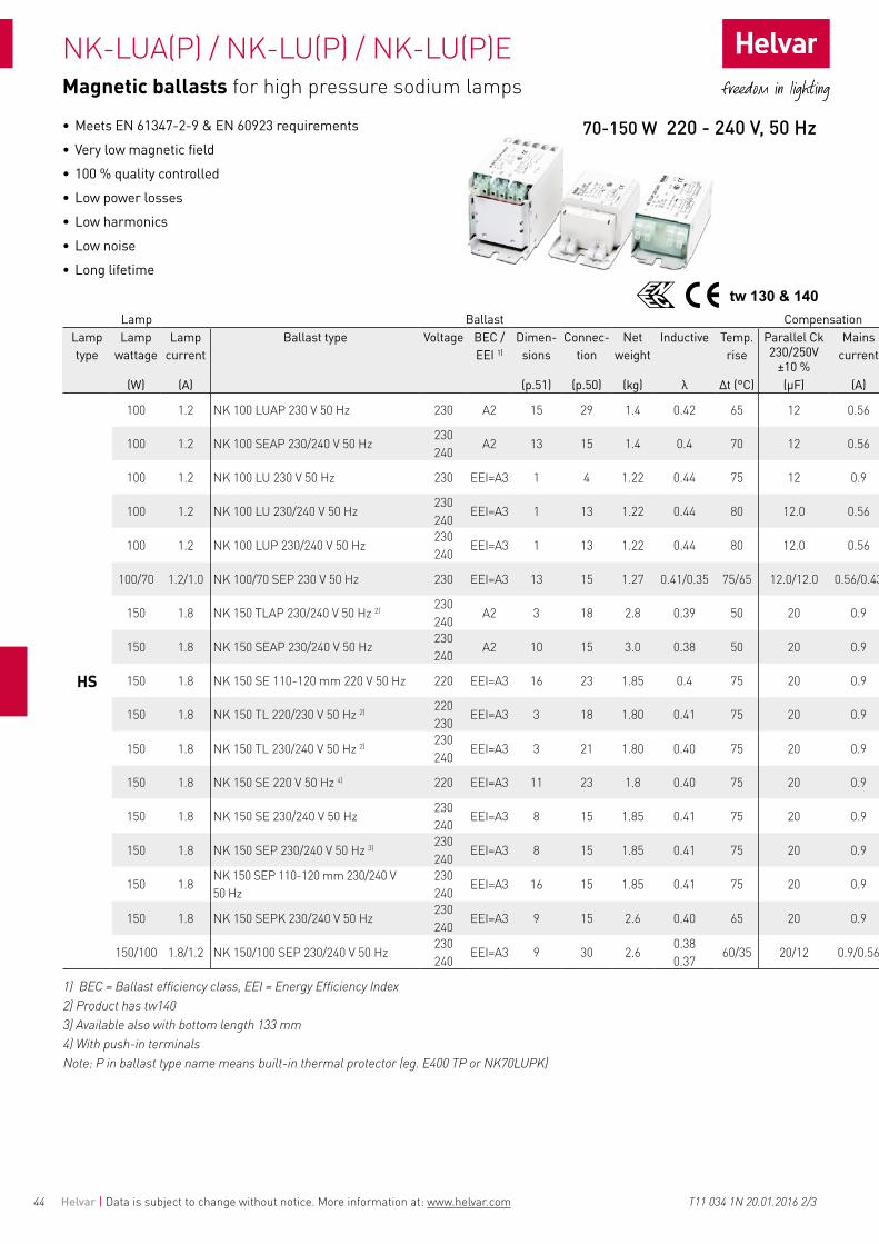
44
tw 130 & 140
NK-LUA(P) / NK-LU(P) / NK-LU(P)E
Helvar | Data is subject to change without notice. More information at: www.helvar.com
Magnetic ballasts for high pressure sodium lamps
Lamp Ballast CompensationLamp type
Lamp wattage
Lamp current
Ballast type Voltage BEC /EEI 1)
Dimen-sions
Connec-tion
Net weight
Inductive Temp.rise
Parallel Ck 230/250V
±10 %
Mains current
(W) (A) (p.51) (p.50) (kg) λ Δt (°C) (µF) (A)
HS
100 1.2 NK 100 LUAP 230 V 50 Hz 230 A2 15 29 1.4 0.42 65 12 0.56
100 1.2 NK 100 SEAP 230/240 V 50 Hz230 240
A2 13 15 1.4 0.4 70 12 0.56
100 1.2 NK 100 LU 230 V 50 Hz 230 EEI=A3 1 4 1.22 0.44 75 12 0.9
100 1.2 NK 100 LU 230/240 V 50 Hz230 240
EEI=A3 1 13 1.22 0.44 80 12.0 0.56
100 1.2 NK 100 LUP 230/240 V 50 Hz230 240
EEI=A3 1 13 1.22 0.44 80 12.0 0.56
100/70 1.2/1.0 NK 100/70 SEP 230 V 50 Hz 230 EEI=A3 13 15 1.27 0.41/0.35 75/65 12.0/12.0 0.56/0.43
150 1.8 NK 150 TLAP 230/240 V 50 Hz 2) 230 240
A2 3 18 2.8 0.39 50 20 0.9
150 1.8 NK 150 SEAP 230/240 V 50 Hz230 240
A2 10 15 3.0 0.38 50 20 0.9
150 1.8 NK 150 SE 110-120 mm 220 V 50 Hz 220 EEI=A3 16 23 1.85 0.4 75 20 0.9
150 1.8 NK 150 TL 220/230 V 50 Hz 2) 220 230
EEI=A3 3 18 1.80 0.41 75 20 0.9
150 1.8 NK 150 TL 230/240 V 50 Hz 2) 230 240
EEI=A3 3 21 1.80 0.40 75 20 0.9
150 1.8 NK 150 SE 220 V 50 Hz 4) 220 EEI=A3 11 23 1.8 0.40 75 20 0.9
150 1.8 NK 150 SE 230/240 V 50 Hz230 240
EEI=A3 8 15 1.85 0.41 75 20 0.9
150 1.8 NK 150 SEP 230/240 V 50 Hz 3) 230 240
EEI=A3 8 15 1.85 0.41 75 20 0.9
150 1.8NK 150 SEP 110-120 mm 230/240 V 50 Hz
230 240
EEI=A3 16 15 1.85 0.41 75 20 0.9
150 1.8 NK 150 SEPK 230/240 V 50 Hz230 240
EEI=A3 9 15 2.6 0.40 65 20 0.9
150/100 1.8/1.2 NK 150/100 SEP 230/240 V 50 Hz230 240
EEI=A3 9 30 2.60.38 0.37
60/35 20/12 0.9/0.56
1) BEC = Ballast efficiency class, EEI = Energy Efficiency Index2) Product has tw1403) Available also with bottom length 133 mm 4) With push-in terminalsNote: P in ballast type name means built-in thermal protector (eg. E400 TP or NK70LUPK)
• Meets EN 61347-2-9 & EN 60923 requirements• Very low magnetic field• 100 % quality controlled• Low power losses• Low harmonics• Low noise• Long lifetime
T11 034 1N 20.01.2016 2/3
70-150 W 220 - 240 V, 50 Hz

45
NK-SE / SEP, NK-T / F
tw 130 & 140
Helvar | Data is subject to change without notice. More information at: www.helvar.com
Lamp Ballast CompensationLamp type
Lamp wattage
Lamp current
Ballast type Voltage BEC /EEI 1)
Dimen-sions
Connec-tion
Net weight
Inductive Temp.rise
Parallel Ck 230/250V
±10 %
Mains current
(W) (A) (p.51) (p.50) (kg) λ Δt (°C) (µF) (A)
HS
100 1.2 NK 100 LUAP 230 V 50 Hz 230 A2 15 29 1.4 0.42 65 12 0.56
100 1.2 NK 100 SEAP 230/240 V 50 Hz230 240
A2 13 15 1.4 0.4 70 12 0.56
100 1.2 NK 100 LU 230 V 50 Hz 230 EEI=A3 1 4 1.22 0.44 75 12 0.9
100 1.2 NK 100 LU 230/240 V 50 Hz230 240
EEI=A3 1 13 1.22 0.44 80 12.0 0.56
100 1.2 NK 100 LUP 230/240 V 50 Hz230 240
EEI=A3 1 13 1.22 0.44 80 12.0 0.56
100/70 1.2/1.0 NK 100/70 SEP 230 V 50 Hz 230 EEI=A3 13 15 1.27 0.41/0.35 75/65 12.0/12.0 0.56/0.43
150 1.8 NK 150 TLAP 230/240 V 50 Hz 2) 230 240
A2 3 18 2.8 0.39 50 20 0.9
150 1.8 NK 150 SEAP 230/240 V 50 Hz230 240
A2 10 15 3.0 0.38 50 20 0.9
150 1.8 NK 150 SE 110-120 mm 220 V 50 Hz 220 EEI=A3 16 23 1.85 0.4 75 20 0.9
150 1.8 NK 150 TL 220/230 V 50 Hz 2) 220 230
EEI=A3 3 18 1.80 0.41 75 20 0.9
150 1.8 NK 150 TL 230/240 V 50 Hz 2) 230 240
EEI=A3 3 21 1.80 0.40 75 20 0.9
150 1.8 NK 150 SE 220 V 50 Hz 4) 220 EEI=A3 11 23 1.8 0.40 75 20 0.9
150 1.8 NK 150 SE 230/240 V 50 Hz230 240
EEI=A3 8 15 1.85 0.41 75 20 0.9
150 1.8 NK 150 SEP 230/240 V 50 Hz 3) 230 240
EEI=A3 8 15 1.85 0.41 75 20 0.9
150 1.8NK 150 SEP 110-120 mm 230/240 V 50 Hz
230 240
EEI=A3 16 15 1.85 0.41 75 20 0.9
150 1.8 NK 150 SEPK 230/240 V 50 Hz230 240
EEI=A3 9 15 2.6 0.40 65 20 0.9
150/100 1.8/1.2 NK 150/100 SEP 230/240 V 50 Hz230 240
EEI=A3 9 30 2.60.38 0.37
60/35 20/12 0.9/0.56
Magnetic ballasts for high pressure sodium lamps
Lamp Ballast CompensationLamp type
Lamp wattage
Lamp current
Ballast type Voltage BEC /EEI 1)
Dimen-sions
Connec-tion
Net weight
Inductive Temp.rise
Parallel Ck 230/250V
±10 %
Mains current
(W) (A) (p.51) (p.50) (kg) λ Δt (°C) (µF) (A)
HS
250 3.0 NK 250 T 220 V 50 Hz 220 EEI=A3 3 25 3.15 0.42 70 32 1.4
250 3.0 NK 250 SEL 220 V 50 Hz 220 EEI=A3 10 23 2.6 0.42 80 32 1.4
250 3.0 NK 250 TLK 220/230 V 50 Hz 220 230 EEI=A3 3 21 2.75 0.43 75 32 1.4
250 3.0 NK 250 TAP 230/240 V 50 Hz 2) 3) 230 240 A2 3 19 3.3 0.4 65 32 1.4
250 3.0 NK 250 SEP 230/240 V 50 Hz 230 240 EEI=A3 10 15 3.00 0.38 75
80 32 1.4
250 3.0 NK 250 T 230 V 50 Hz 2) 3) 230 EEI=A3 3,6 16 3.15 0.42 70 32 1.4
250 3.0 NK 250 T, F 230/240 V 50 Hz 2) 3) 230 240 EEI=A3 3,6 18 3.15 0.42 70
75 32 1.4
250 3.0 NK 250 TLC 220/230 V 50 Hz 2) 3) 220 230 EEI=A3 4 18 3 0.44 65 32 1.4
250 3.0 NK 250 TLPC 230/240 V 50 Hz 2) 3) 230 240 EEI=A3 4 21 3 0.42 65 32 1.4
250 3.0 NK 250 TP, FP 230/240 V 50 Hz 2) 3) 230 240 EEI=A3 3,6 19 3.15 0.42 70
75 32 1.4
250 3.0 NK 250 TLK 220/230 V 50 Hz 3) 220 230 EEI=A3 3 21 2.75 0.43 75 32 1.4
250 3.0 NK 250 TLK 230/240 V 50 Hz 3) 230 240 EEI=A3 3 18 2.75 0.43 75
80 32 1.4
250 3.0 NK 250 TLPK 230/240 V 50 Hz 3) 230 240 EEI=A3 3 19 2.75 0.43 75
80 32 1.4
400 4.4 NK 400 T 230/240 V 50 Hz 2) 3) 230 240 A2 4 18 4.4 0.40 70
75 50 2.2
400 4.4 NK 400 TP, FP 230/240 V 50 Hz 2) 3) 230 240 A2 4,7 19 4.4 0.40 70
75 50 2.2
400 4.4 NK 400 FE 230/240 V 50 Hz 2) 3) 230 240 EEI=A3 4,7 21 3.6 0.41 75 50 2.2
400 4.4 NK 400 TE 220 V 50 Hz 3) 5) 220 A2 4 26 3.6 0.43 75 50 2.2
400 4.4 NK 400 TE 130 mm 230/240 V 50 Hz 2) 3)
230 240 EEI=A3 17 22 4.4 0.43 75 50 2.2
400 4.4 NK 400 TEP, FEP 230/240 V 50 Hz 2) 3) 230 240 EEI=A3 4,7 22 3.6 0.41 75 50 2.2
400 4.4 NK 400 T 220 V 50 Hz 2) 3) 5) 220 A2 4 25 4.4 0.40 70 50 2.2
400 4.4 NK 400 F 230 V 50 Hz 230 EEI=A3 7 16 4.4 0.4 70 50 2.2
400 4.4 NK 400 FP 240 V 50 Hz 240 EEI=A3 7 31 4.4 0.4 75
400 4.4 NK 400 TL 220/230 V 50 Hz 2) 3) 7) 220 230 EEI=A3 4 18 3.8 0.44
0.42 80 50 2.2
400 4.4 NK 400 TLP 220/230 V 50 Hz 2) 3) 7) 220 230 EEI=A3 4 19 3.8 0.44
0.42 80 50 2.2
600 6.2 NK 600 TA/2 230/240 V 50 Hz 2) 3) 4) 230 240 A2 4 20 9.0 0.45 50 65 3
600 6.2 NK 600 T/2 230/240 V 50 Hz 2) 3) 4) 230 240 EEI=A3 6 20 6.3 0.44 75
80 65 3.0
600 6.2 NK 600 TL/2 220 V 50 Hz 220 EEI=A3 4 27 5.5 0.48 65 65 3
600 6.2 NK 600 SE 230 V 50 Hz 230 A2 14 23 6.9 0.47 75 65 3.0
1000 10.3/9.5 NK/H 1000 T/2 220 V 50 Hz 3) 4) 220 (NK) 6) 220 (H) 6) EEI=A3 4 20 8.8 0.45
0.4980 70 100 5.0
1000 10.3 NK 1000 F/2 230/240 V 50 Hz 2) 3) 4) 230 240 EEI=A3 7 20 8.8 0.45 80 100 5.3
5.0
1) BEC = Ballast efficiency class, EEI = Energy Efficiency Index2) T-type = two and four point fixing F-type = four point fixing 3) Product has tw1404) Supplied as 2 identical ballasts both with the dimensions indicated. All other technical values are stated for the combined product operating one lamp.
• Meets EN 61347-2-9 & EN 60923 requirements• Very low magnetic field• 100 % quality controlled• Low power losses• Low harmonics• Low noise• Long lifetime• Multiple fixing point variations
T11 034 1N 20.01.2016 3/3
250-1000 W 220 - 240 V, 50 Hz
5) Can also be used with certain 400 W HI-lamps. Check lamp manufacturers data to ensure they specify that the lamp is suitable for HPS ballast6) NK-output for high pressure sodium lamps, H-output for metal halide lamps7) Not ENEC approvedNote: P in ballast type name means built-in thermal protector (eg. NK400 TP or NK600 SEP)
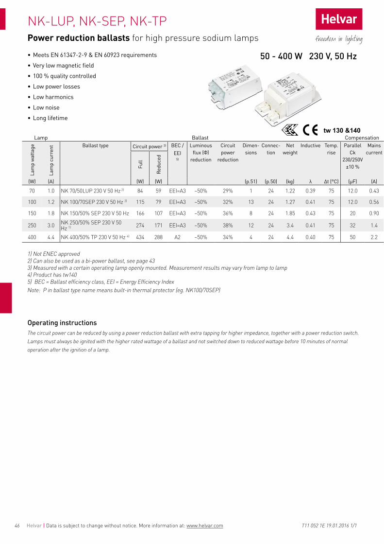
46
NK-LUP, NK-SEP, NK-TP
tw 130 &140
Helvar | Data is subject to change without notice. More information at: www.helvar.com T11 052 1E 19.01.2016 1/1
Power reduction ballasts for high pressure sodium lamps
Lamp Ballast Compensation
Lam
p w
atta
ge
Lam
p cu
rren
t Ballast type Circuit power 3) BEC /EEI
5)
Luminous flux (Φ)
reduction
Circuit power
reduction
Dimen-sions
Connec-tion
Net weight
Inductive Temp.rise
Parallel Ck
230/250V ±10 %
Mains current
Full
Redu
ced
(W) (A) (W) (W) (p.51) (p.50) (kg) λ Δt (°C) (µF) (A)
70 1.0 NK 70/50LUP 230 V 50 Hz 2) 84 59 EEI=A3 ~50% 29% 1 24 1.22 0.39 75 12.0 0.43
100 1.2 NK 100/70SEP 230 V 50 Hz 2) 115 79 EEI=A3 ~50% 32% 13 24 1.27 0.41 75 12.0 0.56
150 1.8 NK 150/50% SEP 230 V 50 Hz 166 107 EEI=A3 ~50% 36% 8 24 1.85 0.43 75 20 0.90
250 3.0 NK 250/50% SEP 230 V 50 Hz 1) 274 171 EEI=A3 ~50% 38% 12 24 3.4 0.41 75 32 1.4
400 4.4 NK 400/50% TP 230 V 50 Hz 4) 434 288 A2 ~50% 34% 4 24 4.4 0.40 75 50 2.2
1) Not ENEC approved2) Can also be used as a bi-power ballast, see page 433) Measured with a certain operating lamp openly mounted. Measurement results may vary from lamp to lamp4) Product has tw1405) BEC = Ballast efficiency class, EEI = Energy Efficiency IndexNote: P in ballast type name means built-in thermal protector (eg. NK100/70SEP)
Operating instructionsThe circuit power can be reduced by using a power reduction ballast with extra tapping for higher impedance, together with a power reduction switch. Lamps must always be ignited with the higher rated wattage of a ballast and not switched down to reduced wattage before 10 minutes of normal operation after the ignition of a lamp.
• Meets EN 61347-2-9 & EN 60923 requirements• Very low magnetic field• 100 % quality controlled• Low power losses• Low harmonics• Low noise• Long lifetime
50 - 400 W 230 V, 50 Hz

47
NK-LU(P) / SE / SEP(K) / TL(P)
tw 130 & 140
Helvar | Data is subject to change without notice. More information at: www.helvar.com
Magnetic ballasts for metal halide lamps
Lamp Ballast CompensationLamp type
Lamp wattage
Lamp current
Ballast type Voltage BEC /EEI 1)
Dimen-sions
Connec-tion
Net weight
Inductive Temp.rise
Parallel Ck 230/250V
±10 %
Mains current
(W) (A) (p.51) (p.50) (kg) λ Δt (°C) (µF) (A)
HI
35 0.53 NK 35 LU 230/240 V 50 Hz 230 240 EEI=A3 1 13 1.22 0.38 50 6 0.23
35 0.53 NK 35 LUP 230/240 V 50 Hz 230 240 EEI=A3 1 15 1.22 0.38 50 6.0 0.33
50 0.76 NK 50 LUAP 230 V 50 Hz 230 A2 15 29 1.4 0.34 40 8 0.33
50 0.76 NK 50 LU 230/240 V 50 Hz 6) 230 240 EEI=A3 1 13 1.22 0.38 70 8 0.33
50 0.76 NK 50 LUP 230/240 V 50 Hz 6) 230 240 EEI=A3 1 15 1.22 0.38 70 8 0.33
70/50 1.0/0.76 NK 70/50 LU 230/240 V 50 Hz 6) 230 240 EEI=A3 1 14 1.22 0.39/0.38 75/60 12.0/8.0 0.43/0.33
70/50 1.0/0.76 NK 70/50 LUP 230 V 50 Hz 6) 230 EEI=A3 1 15 1.22 0.39/0.38 75/60 12.0/8.0 0.43/0.33
70 1 NK 70 LU 220 V 50 Hz 220 EEI=A3 1 4 1.22 0.39 70 12 0.43
70 1.0 NK 70 LU 240 V 50 Hz 240 EEI=A3 1 28 1.22 0.39 70 12.0 0.43
70 1 NK 70 LUAP 230/240 V 50 Hz 230 240 A2 15 3 1.4 0.35 55 12 0.43
70 1.0 NK 70 LUP 230/240 V 50 Hz 230 240 EEI=A3 1 15 1.22 0.39 70 12.0 0.43
70 1.0 NK 70 LUPK 240 V 50 Hz 240 EEI=A3 1 29 1.22 0.39 65 12.0 0.43
70 1.0 NK 70 LUPK 230/240 V 50 Hz 230 240 EEI=A3 1 15 1.22 0.39 65 12.0 0.43
70 1.0 NK 70 LUE 220 V 50 Hz 220 EEI=A3 1 28 1.18 0.39 75 12.0 0.43
70 1 NK 70 LUE 230 V 50 Hz 230 EEI=A3 1 4 1.2 0.38 75 12 0.43
70 1.0 NK 70 LUE 230/240 V 50 Hz 230 240 EEI=A3 1 13 1.22 0.38
0.3675 80 12.0 0.56
70 1.0 NK 70 LUPE 230/240 V 50 Hz 230 240 EEI=A3 1 15 1.20 0.38
0.3675 80 12.0 0.56/0.43
100 1.2 NK 100 LUAP 230 V 50 Hz 230 A2 15 29 1.4 0.42 65 12 0.56
100 1.2 NK 100 LU 230 V 50 Hz 230 EEI=A3 1 4 1.22 0.44 75 12 0.56
100 1.1 NK 100 LUP 230/240 V 50 Hz 230 240 EEI=A3 1 13 1.22 0.44 80 12.0 0.9
100/70 1.1/1.0 NK 100/70 SEP 230 V 50 Hz 230 EEI=A3 13 13 1.27 0.41/0.35 75/65 12.0/12.0 0.9
150 1.8 NK 150 TLAP 230/240 V 50 Hz 2) 3) 230 240 A2 3 18 2.8 0.39 50 20 0.9
150 1.8 NK 150 SEAP 230/240 V 50 Hz 230 240 A2 10 15 3 0.38 50 20 0.9
150 1.8 NK 150 TL 220/230 V 50 Hz 2) 3) 220 230 EEI=A3 3 18 1.80 0.41 75 20 0.9
150 1.8 NK 150 TL 230/240 V 50 Hz 2) 3) 230 240 EEI=A3 3 21 1.80 0.40 75 20 0.9
150 1.8 NK 150 SEP 230/240 V 50 Hz 4) 5) 230 240 EEI=A3 8 15 1.85 0.41 75 20 0.9
150 1.8 NK 150 SEPK 230/240 V 50 Hz 4) 230 240 EEI=A3 9 15 2.6 0.40 65 20 0.9
150 1.8 NK 150 SE 110-120 mm 220 V 50 Hz 220 EEI=A3 16 23 1.85 0.4 75 20 0.9
150 1.8 NK 150 SEP 110-120 mm 230/240 V 50 Hz
230 240 EEI=A3 16 15 1.85 0.41 75 20 0.9
1) BEC = Ballast efficiency class, EEI = Energy Efficiency Index2) T-type = two and four point fixing, F-type = four point fixing3) Product has tw1404) With push-in terminals
• Meets EN 61347-2-9 & EN 60923 requirements• Very low magnetic field• 100 % quality controlled• Low power losses• Low harmonics• Low noise• Long lifetime• Multiple fixing point variations
T11 037 1O 20.01.2016 1/2
35-150 W 220 - 240 V, 50 Hz
5) Available also with bottom length 133 mm6) 50 W : Only suitable with CDO lampsNote: P in ballast type name means built-in thermal protector (eg. NK70LUPK)

48
NK-SE, NK-TE, NK-T(P) / F, E-T / F, H-F/2
tw 130 & 140
Helvar | Data is subject to change without notice. More information at: www.helvar.com
Magnetic ballasts for metal halide lamps
Lamp Ballast CompensationLamp type
Lamp wattage
Lamp current
Ballast type Voltage BEC /EEI Dimen-sions
Connec-tion
Net weight
Inductive Temp.rise
Parallel Ck 230/250V
±10 %
Mains current
(W) (A) 1) (p.51) (p.50) (kg) λ Δt (°C) (µF) (A)
HI
250 3.0 NK 250 T 220 V 50 Hz 220 EEI=A3 3 25 3.15 0.42 70 32 1.4
250 3.0 NK 250 TLK 220/230 V 50 Hz 5) 220 230 EEI=A3 3 21 2.75 0.43 75 32 1.4
250 3.0 NK 250 TAP 230/240 V 50 Hz 5) 230 240 A2 3 19 3.3 0.4 65 32 1.4
250 3.0 NK 250 TLK 230/240 V 50 Hz 5) 230 240 EEI=A3 3 18 2.75 0.43 75
80 32 1.4
250 3.0 NK 250 TLPK 230/240 V 50 Hz 5) 230 240 EEI=A3 3 19 2.75 0.43 75
80 32 1.4
250 3.0 NK 250 SEL 220 V 50 Hz 220 EEI=A3 10 23 2.6 0.42 80 32 1.4
250 3.0 NK 250 SEP 230/240 V 50 Hz 230 240 EEI=A3 10 15 3.00 0.38 75
80 32 1.4
250 3.0 NK 250 TP, FP 230/240 V 50 Hz 2) 5) 230 240 EEI=A3 3,6 19 3.15 0.42 70
75 32 1.4
400 3.5 E 400 SE 230 V 50 Hz 230 A2 10 23 3.00 0.51 80 35 2.2
400 3.5 E 400 SE 240 V 50 Hz 240 A2 10 23 3.00 0.49 80 35 2.2
400 4.1 NK 400 F 230 V 50 Hz 230 EEI=A3 7 16 4.4 0.4 70 45 2.2
400 4.1 NK 400 FP 240 V 50 Hz 240 EEI=A3 7 31 4.4 0.4 75 45 2.2
400 4.1 NK 400 TP, FP 230/240 V 50 Hz 2) 4) 5) 230 240 A2 4,7 19 4.40 0.40 70
75 45 2.2
400 4.1 NK 400 FE 230/240 V 50 Hz 2) 4) 5) 230 240 A2 7 21 3.6 0.41 75 45 2.2
400 4.1 NK 400 TE 130 mm 230/240 V 50 Hz 5)
230 240 A2 17 22 4.4 0.43 75 45 2.2
400 4.1 NK 400 TEP, FEP 230/240 V 50 Hz
2) 4) 5)230 240 A2 4,7 22 3.6 0.41 75 45 2.2
400 4.1 NK 400 TL, TLP 220/230 V 50 Hz
2) 5) 7) 220 230 EEI=A3 4 18,19 3.8 0.44
0.42 80 45 2.2
400 3.5 H 400 T 230/240 V 50 Hz 2) 5) 230 240 A2 3 18 3.18 0.48 70
75 35 2.2
400 3.5 H 400 TP 230/240 V 50 Hz 2) 5) 230 240 A2 3 22 3.18 0.48 70
75 35 2.2
400 3.5 E 400 TLC 220/230 V 50 Hz 2) 5) 220 230 A2 4 21 3.6 0.55 65 35 2.15
400 3.5 E 400 TLC 230/240 V 50 Hz 2) 5) 230 240 A2 4 18 3.7 0.53 65 35 2.15
400 3.5 E 400 TLPC 230/240 V 50 Hz 2) 5) 230 240 A2 4 19 3.7 0.53 65 35 2.15
400 3.5 E 400 T 220 V 50 Hz 2) 5) 220 A2 3 25 3.15 0.49 80 35 2.15
400 3.5 E 400 T 230 V 50 Hz 2) 5) 230 A2 3 16 3.16 0.49 80 35 2.15
400 3.5 E 400 F 230/240 V 50 Hz 2) 5) 230 240 A2 6 18 3.16 0.49 80 35 2.15
400 3.5 E 400 TL 220 V 50 Hz 2) 5) 220 A2 4 17 3.0 0.53 75 35 2.15
400 3.5 E 400 TL 220/230 V 50 Hz 5) 220 230 A2 4 18 3.0 0.55 75 35 2.15
400 3.5 E 400 TLP 230/240 V 50 Hz 5) 230 240 A2 4 22 3.1 0.53 75
80 35 2.15
400 3.5 E 400 TP, FP 230/240 V 50 Hz 2) 5) 230 240 A2 3,6 22 3.16 0.49 80 35 2.15
1000 10.3/9.5 NK/H 1000 T/2 220 V 50 Hz 3) 5) 220 (NK) 6) 220 (H)
6) A2 4 20 8.8 0.45
0.4980 70 100 5.0
1000 9.5 H 1000 F/2 230/240 V 50 Hz 2) 3) 5) 230 240 EEI=A3 4 20 8.8 0.49 85 100 4.6
1) BEC = Ballast efficiency class, EEI = Energy Efficiency Index2) T-type = two and four point fixing, F-type = four point fixing3) Supplied as 2 identical ballasts both with the dimensions indicated. All other technical values are stated for the combined product operating one lamp 4) Check lamp manufacturers data to ensure they specify that the lamp is suitable for HPS ballast
• Meets EN 61347-2-9 & EN 60923 requirements• Very low magnetic field• 100 % quality controlled• Low power losses• Low harmonics• Low noise• Long lifetime• Multiple fixing point variations
T11 037 1O 20.01.2016 2/2
250-1000 W 220 - 240 V, 50 Hz
5) Product has tw1406) NK-output for high pressure sodium lamps, H-output for metal halide lamps7) Not ENEC approvedNote: P in ballast type name means built-in thermal protector (eg. E400 TP or NK70LUPK)

4949
NK-LU, NK-SEP, NK-T, NK-TE, NK-TL(C), NK-F/2
tw 130 & 140
Helvar | Data is subject to change without notice. More information at: www.helvar.com
Magnetic ballasts for high intensity discharge lamps
• Meets EN 61347-2-9 & EN 60923 requirements• Very low magnetic field• 100 % quality controlled• Low power losses• Low harmonics• Low noise• Long lifetime
Lamp Ballast CompensationLamp type
Lamp wattage
Lamp current
Ballast type Voltage Dimen-sions
Connec-tion
Net weight
Inductive Temp.rise
Parallel Ck 230/250V
±10 %
Mains current
(W) (A) (V) (p.51) (p.50) (kg) λ Δt (°C) (µF) (A)
HS / HI
50 0.76 NK 50 LU 220/230 V 60 Hz 5) 220 230 1 13 1.22 0.38 70 6 0.33
70 1.0 NK 70 LU 220/230 V 60 Hz 5) 220 230 1 13 1.22 0.39 65 10 0.43
70 1.0 NK 70 LUP 220/230 V 60 Hz 5) 220 230 1 17 1.22 0.39 65 10 0.43
100 1.2 NK 100 LU 220 V 60 Hz 5) 220 1 28 1.22 0.44 75 10 0.56
150 1.8 NK 150 SEP 220 V 60 Hz 5) 220 8 23 1.85 0.44 75 16 0.9
150 1.8 NK 150 TL 220 V 60 Hz 2) 6) 220 2 25 1.8 0.42 75 16 0.9
250 3.0 NK 250 TLC 220 V 60 Hz 2) 6) 220 3 25 2.75 0.45 65 25 1.4
250 3.0 NK 250 TLK 220 V 60 Hz 2) 6) 220 3 17 2.75 0.42 65 25 1.4
250 3.0 NK 250 T 220 V 60 Hz 2) 6) 220 3 17 3.15 0.42 65 25 1.4
HS
400 4.4 NK 400 TE 220 V 60 Hz 2) 6) 220 4 25 3.6 0.45 80 40 2.2
400 4.4 NK 400 TL 220 V 60 Hz 2) 6) 220 4 17 3.7 0.45 80 40 2.2
400 4.4 NK 400 T 220 V 60 Hz 2) 6) 220 4 17 4.4 0.47 65 40 2.2
1000 10.3 NK 1000 F/2 220 V 60 Hz 3) 4) 6) 220 7 27 8.8 0.45 80 80 5.3
HI400 3.5 E 400 TL 220/230 V 60 Hz 2) 6) 220
230 4 11 3 0.560.54 75 25 2.15
1000 9.5 H 1000 F/2 220 V 60 Hz 3) 4) 6) 220 7 27 8.8 0.51 80 80 4.6
HM 400 3.25 E 400 TL 220/230 V 60 Hz 2) 6) 220 230 4 11 3 0.56
0.54 75 20 2.15
1) Winding at 25 °C2) T-type = two and four point fixing3) F-type = four point fixing4) Supplied as 2 identical ballasts both with the dimensions indicated All other technical values are stated for the combined product operating one lamp 5) With push-in terminals6) Product has tw140
T11 069 1B 20.01.2016
50-1000 W 220 V, 230V 60 Hz

50
1 4
7
18
21
25
24
28
20
23
27
31
14
10
2
5 8
15
11
3
6
17
13
9
16
12
19
22
26
Ф ~50%Power reduction switch
29 30
Helvar | Data is subject to change without notice. More information at: www.helvar.com
Connection diagrams
HID-ballasts
T11 053 1E 20.01.2016 1/2
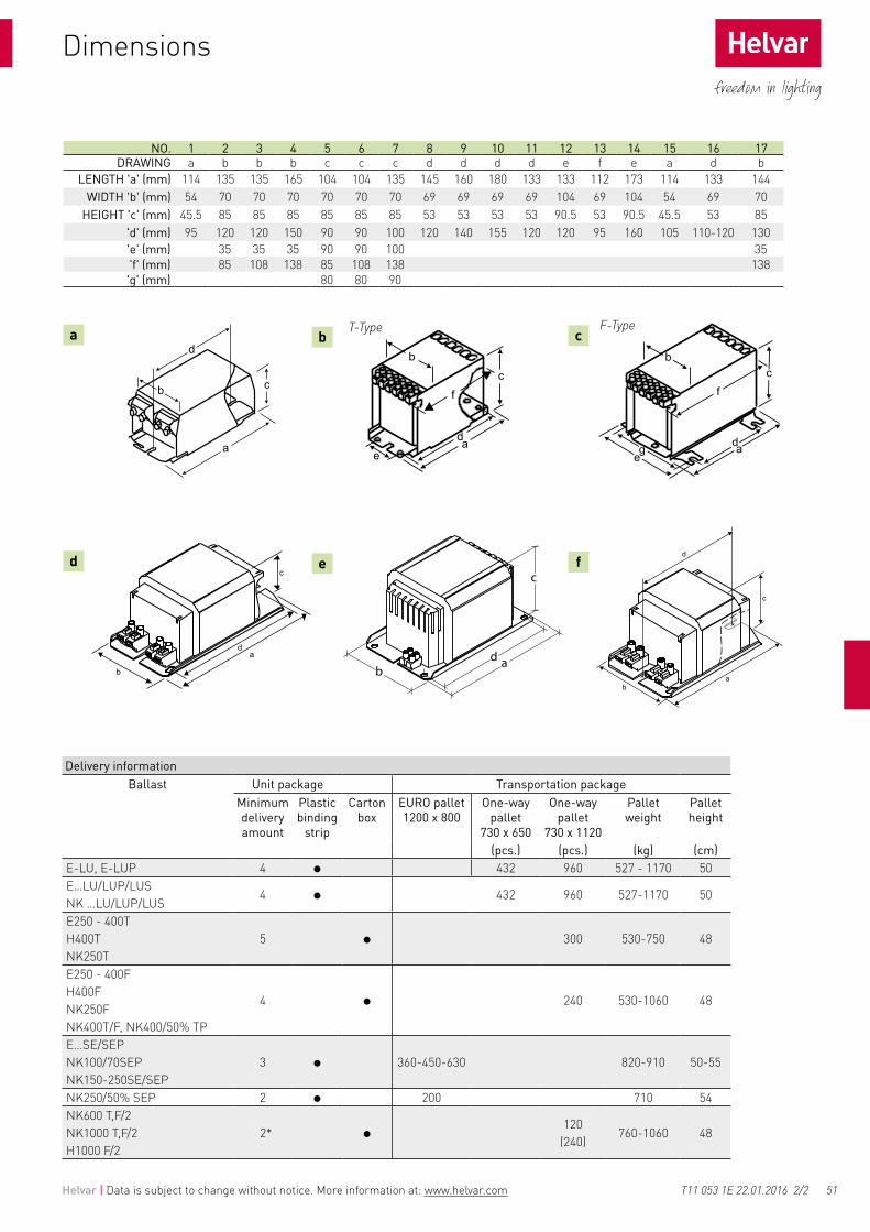
51
a
d
b
e
c
f
T-Type F-Type
ad
c
ba
d
c
b
Helvar | Data is subject to change without notice. More information at: www.helvar.com
Dimensions
Delivery informationBallast Unit package Transportation package
Minimum delivery amount
Plastic binding
strip
Carton box
EURO pallet 1200 x 800
One-way pallet
730 x 650
One-way pallet
730 x 1120
Pallet weight
Pallet height
(pcs.) (pcs.) (kg) (cm)E-LU, E-LUP 4 432 960 527 - 1170 50E…LU/LUP/LUS NK …LU/LUP/LUS
4 432 960 527-1170 50
E250 - 400T H400T NK250T
5 300 530-750 48
E250 - 400F H400F NK250F NK400T/F, NK400/50% TP
4 240 530-1060 48
E…SE/SEPNK100/70SEP NK150-250SE/SEP
3 360-450-630 820-910 50-55
NK250/50% SEP 2 200 710 54NK600 T,F/2 NK1000 T,F/2 H1000 F/2
2*120
(240)760-1060 48
NO. 1 2 3 4 5 6 7 8 9 10 11 12 13 14 15 16 17DRAWING a b b b c c c d d d d e f e a d b
LENGTH 'a' (mm) 114 135 135 165 104 104 135 145 160 180 133 133 112 173 114 133 144WIDTH 'b' (mm) 54 70 70 70 70 70 70 69 69 69 69 104 69 104 54 69 70
HEIGHT 'c' (mm) 45.5 85 85 85 85 85 85 53 53 53 53 90.5 53 90.5 45.5 53 85 'd' (mm) 95 120 120 150 90 90 100 120 140 155 120 120 95 160 105 110-120 130 'e' (mm) 35 35 35 90 90 100 35 'f' (mm) 85 108 138 85 108 138 138 'g' (mm) 80 80 90
T11 053 1E 22.01.2016 2/2

52
tw 130
Helvar | Data is subject to change without notice. More information at: www.helvar.com
Electronic superimposed pulse ignitors
Note: Suitability for lamps refers to most common lamps acc. to EN standards. Check also lamp manufacturer information of proper ignitor selection. Not suitable for lamps with low ignition voltage (~1 kV)1) See also recommended combinations, dimensions and connection on page 532) Not ENEC approvedMinimum delivery amount 50 pcs.
• Fully electronic • Super-imposed pulse type• Compact design• Solid metal fixing screw• Low inherent heating• High thermal resistance• Low power losses• ENEC approved
T17 009 1A 19.02.2014 1/2
220-240 V, 50-60 Hz
• Intelligent timer with µC for light source protection and energy saving operation
• Protective against power-line overvoltage• Lamp protection during ignition• Continuous lamp-state check• Stable ignition over a wide temperature range• Radio-frequency interference level 10 % to standard
timed version• Long life performance• Approval to EN 61347, EN 60927, EN 55014
Additional specifications and cut-out sequence for LSI-400ST20 & LSI-600T20
Max. contin. lamp current
Cut out time
Ignition voltage
Impulse width
Internal losses
(A) (min) (kV) (µs) (W)L-70 1 - 1.9 ... 2.3 2 (1.5 kV) < 1.0 (25 °C; 1 A)L-150 1.8 - 4.0 ... 4.5 1.4 (2.0 kV) < 1.0 (25 °C; 1.8 A)HI-400M 4.6 - 4.0 ... 4.5 1.0 (2.0 kV) < 3.4 (25 °C; 4.6 A)HI-400S 4.6 - 4.0 ... 4.5 1.0 (2.0 kV) < 3.3 (25 °C; 4.6 A)L-600 6.5 - 4.0 ... 4.5 1.2 (2.0 kV) < 4.0 (25 °C; 6.5 A)L-1000S 2) 12 - 4.0 ... 4.5 1.5 (2.0 kV) < 6.0 (25 °C; 12 A)
LSI-70T1 1 2 1.9 ... 2.3 2 (1.5 kV) <1.0 (25 °C; 1A)LSI-150T20 1.8 20 4.0 ... 4.5 1.4 (2.0 kV) <1.0 (25 °C;1.8 A)LHI-400ST10 4.6 18 3.5 ... 4.5 1.0 (2.0 kV) <3.0 (25 °C; 4.6 A)LSI-400ST20 4.6 DIGITAL 4.0 ... 4.5 0.9 (2.0 kV) <3.3 (25 °C; 4.6 A)LSI-600T20 6.5 DIGITAL 4.0 ... 4.5 1.2 (2.0 kV) <4.0 (25 °C; 6.5 A)LSI-1000T10 2) 12 18 4.0 ... 4.5 1.7 (2.0 kV) <6.0 (25 °C; 12 A)
Technical DataOperating voltage 198-264 V, 50-60 HzCut-out voltage ≤ 170 VPhasing 60-90 / 240-270 °elPulses per half cycle 3 *Max. load capacitance 100 pF **Max. housing temp. 105 °CMin. ambient temp. - 30 °C*) 2 for L-70 & LSI-70T1**) 200 for L-70 & LSI-70T1
ConnectionTerminals: 3-pole D-L-N 2.5 mm2 max

53Helvar | Data is subject to change without notice. More information at: www.helvar.com
Helvar ignitors for high pressure sodium and metal halide lamps
Dimensions
T17 009 1A 19.02.2014 2/2
T1 Automatic cut-out 2 minT10 Automatic cut-out 18 minT20 Automatic cut-out 20 min
Recommended combination
Ignitor HIGH PRESSURE SODIUM CERAMIC METAL HALIDE METAL HALIDE 1)
Watt 35 50 70 100 150 250 400 600 1000 35 70 100 150 250 400 35 70 100 150 250 400 1000
L-70
LSI-70T1
L-150 DE3)
LSI-150T20 DE3)
HI-400M DE3) 2) 2) 2) 2)
HI-400S DE3) 2) 2) 2) 2)
LHI-400ST10 DE3) 2) 2) 2) 2)
LSI-400ST20 DE3) 2) 2) 2) 2)
L-600 DE3) 2) 2) 2) 2) 2) 2) 2) 2)
LSI-600T20 DE3) 2) 2) 2) 2) 2) 2) 2) 2)
L-1000S DE3) 2) 2) 2) 2) 2) 2) 2) 2) 2) 2)
LSI-1000T10 DE3) 2) 2) 2) 2) 2) 2) 2) 2) 2) 2)
Note: Suitability for lamps refers to most common lamps acc. to EN standards. Check also lamp manufacturer information of proper ignitor selection.1) Not suitable for lamps with low ignition voltage (~1 kV)2) Used combination3) DE means double ended lamp
Ignitor A X B X C (mm) Weight (g)L-70 88x34x28 130L-150 88x34x28 130HI-400M 92x34x28 130HI-400S 92x38x32 160L-600 92x43x36 230L-1000 / L-1000S 108x55x43 460LSI-70T1 88x34x28 130LSI-150T20 88x34x28 130LHI-400ST10 92x38x32 160LSI-400ST20 92x38x32 160LSI-600T20 92x43x36 230LSI-1000T10 108x55x43 460

54 Helvar | Data is subject to change without notice. More information at: www.helvar.com
Instructions for use - electronic ballasts for fluorescent lamps
Helvar ballast and ignitors are designed to be built into luminaires. Safe and reliable operation of the components requires that the luminaire complies with the relevant standards and regulations (e.g. IEC 60598-1). The luminaire shall be designed to adequately protect the control gear from dust, moisture and pollution. The luminaire manufacturer remains responsible for the correct choice and installation of the control gear according to the application. Specifications of the control gear shall not be exceeded when it is used in the luminaire in the actual operating conditions. The ballast shall not be used outside the luminaire.
For further information and troubleshooting please visit: www.helvar.com/downloads/product-documentation/support-documentation
Wire type
• Solid core conductor only
Wire cross section dimensions
• 0.5 - 1.5 mm² (EL-s-u 0.5 - 0.75 mm²)
Wiring insulation
• According to recommendations in EN 60598
Maximum wire lengths
• See Characteristics table
Wire connections
• As shown on the ballast label and the Wiring Diagram datasheets
Wire preparation
• Strip length 7.5 mm ± 1 mm
Wiring capacitance
• 80 pF / metre (max. for adviced wire lengths)
Wire insertion force
• 8 Newtons (typical)
Wire release from ballast
• (See detailed release instructions on page 168)
Wiring layout
• Keep all wiring as short as possible (particularly the ‘Hot’ wires - see Wiring Diagrams datasheets)
• ‘Hot’ wires should be of equal length
• ‘Cold’ wires should be of equal length
• Always run mains wiring, lamp wiring and low voltage control wiring separate from each other
• Do not run hot and cold lamp wires bunched together
• Lamp wires of two or more separate ballast should not be run together
Installation & operational considerationsWiring considerations
Ballast earthing
• EL-s, EL-ngn, EL-ngn5, EL-es and EL-TCs ranges operationally suitable for both Class I & II fittings (no earth required). However to ensure full EMC compatibility a functional earthing might be required
• All other Helvar electronic ballasts require a functional earth to be connected to ensure reliable operation
Maximum tc temperature
• Reliable operation and lifetime is only guaranteed if the maximum tc point temperature is not exceeded under the conditions of use
Frequent switching
• Helvar warm start ballasts may be used in conjunction with occupancy sensors (PIR) as long as the ‘OFF’ period is greater than 1 minute. Frequently used ‘OFF’ periods shorter than 1 minute may reduce lamp life
Master / Slave connection
• Not advised
Switching off one lamp via lamp wires
• Not permitted
Starting aid
• For a reliable lamp ignition the use of metal starting aid is recommended
• For reliable starting (and electrical safety) all metal parts of the fitting must be at the same electrical potential as the ballast case
Reflector position
• Placing a reflector or metal plate very close to the lamp may increase RFI emissions and cause excessive leakage current of the fitting
• See lamp standards for recommendations
Fitting components
• Ensure the correct electrical ratings for the lamps are used (e.g. 500V rated lampholders are required for T5 lamps)
Ballast mounting position
• Ensure that the entire length of the ballast lies against a flat surface to ensure good heat dissipation
O10 134 1M 19.02.2014 1/2

55Helvar | Data is subject to change without notice. More information at: www.helvar.com
Instructions for use - electronic ballasts for fluorescent lamps
The stand-by function is designed specifically as a protection for the ballast. It will switch the lamps off when an ‘end of lifetime’ condition occurs. Lamps can also fail in many other ways. As such, the exact operating state of the ballast under other lamp fault conditions depends on the specific failure. The ballast will not be harmed under any normal lamp failure condition. Ballasts can be reset from stand-by either by switching the mains supply off and then on, or by replacing the faulty lamps.
Lamp ‘end of lifetime’ • Behaviour of the ballast at end of lamp life time:
IEC 61347-2-3 17.2.• If the lamp electrical characteristics (e.g. lamp voltage) exceed
the ballast internal preset values, the ballast will recognise that a lamp/s has reached the end of its useful operational life. The ballast will then switch off the supply to the lamps to prevent unnecessary stress to the circuit.
Emergency inverter units Due to our continuing program of product development and improvement, Helvar ballast designs are evolving constantly. This natural evolution may affect compatibility between our electronic ballasts and emergency conversion modules. It is therefore the responsibility of either the fitting manufacturer, emergency unit supplier and/or system integrator to ensure the used combination is fully compatible.
Emergency inverter unit recommendations • Use a 4 pole changeover device, with all 4 poles being used to
disconnect the lamp.• Disconnect the mains supply from the ballast before disconnecting
the emergency lamp, and prior to the lamps connection to the emergency unit.
• Reconnect the emergency lamp to the ballast before applying the mains supply.
• For multiple lamp ballasts, the wiring lengths for emergency and non-emergency lamps should be equal.
Stand-by function
Site considerationsInsulation resistance testing on an installation• Carry out insulation resistance testing with the fittings disconnected
from the mains supply (the fitting has already been tested by the manufacturer)
• If fittings are connected to the mains supply during an insulation resistance test, all Live phases and Neutral must be connected together before the test is carried out.
• Ensure correct reconnection before the mains supply is reapplied.
Mixed technology on the same electrical circuit• Do not mix magnetic and electronic ballasts on the same electrical
circuit. The energy spikes from magnetic ballasts may damage electronic ballasts.
Infra-red (IR) system• Fluorescent lamps emit not only visible light, but also infra-red
light. In some cases this may cause interference to IR systems. To minimise problems the IR system should have a reduced receiving area. To guarantee successful functionality the manufacturer of the IR system should be contacted prior to installation. Helvar ballasts typically operate at frequencies rarely used in IR applications.
3-phase supplies• Do not apply power to the ballast / fitting without the Neutral
conductor connected.• Do not disconnect the Neutral conductor unless the supply is off.
Miniature Circuit Breakers (Please refer page 59)• ‘Type C’ MCB’s with trip characteristics in according to EN 60898
are recommended.• 'Type B’ MCB’s are not recommended due to their sensitivity. If
used, load only to 60 % of the equivalent ‘Type C’ MCB.
Class II luminaires:Helvar electronic ballasts can be used in suitably designed class II luminaires. The following points must be very carefully noted:
• EL-sc and EL-iDim / EL-iDim-c ballasts must have functional earth connected
• Luminaire standard EN 60598 provides full details of the requirements for class II luminaires
• Starting aid may be required for reliable operating and EMC performance
Lamp “burn in”:Brand new lamps may occasionally have an uneven distribution of internal gases. This can lead to unreliable starting or uneven light distribution from the lamp. Helvar recommend that new lamps are operated at full output (“burnt in”) for 100 hours prior to being dimmed.
DALI controls:Currently the DALI standard only governs compatibility of load interfaces such as electronic ballasts and LED drivers. For other units, like sensors and control devices, the compatibility assurance is in process. Until the standard for these is finalised, the total system compatibility must be ensured at the system design / integrator stage.
Installation & operational considerations
O10 134 1M 19.02.2014 2/2

56 Helvar | Data is subject to change without notice. More information at: www.helvar.com
Instructions for use - magnetic ballasts & ignitors
Helvar ballast and ignitors are designed to be built into luminaires. Safe and reliable operation of the components requires that the luminaire complies with the relevant standards and regulations (e.g. IEC 60598-1). The luminaire shall be designed to adequately protect the control gear from dust, moisture and pollution. The luminaire manufacturer remains responsible for the correct choice and installation of the control gear according to the application. Specifications of the control gear shall not be exceeded when it is used in the luminaire in the actual operating conditions. The ballast shall not be used outside the luminaire.
Wire type• Push in terminals: Solid core conductor only• Screw terminals: Solid core or stranded conductor
Wiring insulation • According to recommendations in EN 60598
Wire cross section dimensions• Push in terminals: 0.5 - 1.0 mm² (0.5 - 1.5 mm² for HID lamp ballasts)• Screw terminals: 1.5 - 3.0 mm²
Wire preparation • Push in terminals: Strip length 8.0 - 9.0 mm
• Screw terminals: Strip length 7.0 mm ± 1 mm
Wire connections • As shown on the ballast label and the Wiring Diagram datasheets
Mineral insulated cable • Not advised
Wire release from ballast• Push in terminals: Use a 1 mm² solid pin (or similar)• Screw terminals: Flat blade screwdriver
More detailed release instructions on page 62
Wiring layoutKeep all wiring as short as possible• Mains wiring and lamp should always be kept as far as possible
from each-other• Mains wiring should not be bunched together with lamp wiring• Avoid wiring ‘loops’ (to minimise magnetic coupling effect)
• Avoid long parallel cable runs
Wire type • Solid core or stranded conductor
Wiring insulation • According to recommendations in EN 60598
Wire cross section dimensions• 1.5 - 3.0 mm² or 2.0 - 4.0 mm² (depending upon ignitor type)• 2.5 - 5.0 mm² (1000 W ignitors)
Wire connections • As shown on the ignitor label and datasheet
Mineral insulated cable • Not advised
Wire preparation • Strip length 7.0 mm ± 1 mm
Wire release from ignitor • Flat blade screwdriver
Wiring layout • Keep wiring from the ignitor to the lamp as short as possible
1. Fluorescent and HID lamp ballasts
Wiring considerations
2. Ignitors for HID lamps
O10 134 1E 19.02.2014 1/2

57Helvar | Data is subject to change without notice. More information at: www.helvar.com
Instructions for use - magnetic ballasts & ignitors
Mixed technology on the same electrical circuit• Magnetic and electronic ballasts should not be connected to the
same electrical circuit. The energy spikes produced by magnetic ballasts may result in damage to the electronic ballasts
Miniature Circuit Breakers• ‘Type C’ MCB’s having trip characteristics in accordance with
EN 60898 are recommended.• ‘Type B’ MCB’s are not recommended due to their sensitivity. If
used, they must only be loaded to 60 % of the equivalent ‘Type C’ MCB
Ballast earthing • Required for safety
Lifetime • Reliable operation and lifetime is only guaranteed if the
maximum winding temperature of tw 130 ºC is not exceeded under the conditions of normal use
Ballast mounting • The ballast must be located in such a position as to ensure that
its maximum winding temperature of tw 130 ºC is not exceeded under the conditions of normal use
• Mount the ballast against a flat surface to ensure good heat dissipation
Starting aid • For reliable starting (and electrical safety) all metal parts of the
fitting must be at the same electrical potential as the ballast case
Fitting components • Ensure the correct electrical ratings for the lamps being used
Ignitor choice • Helvar ballasts for Metal Halide or High Pressure Sodium lamps
are only suitable for use with superimposed pulse type ignitors• Pulsar type ignitors (where a high starting voltage is applied to
the ballast windings) are not suitable for Helvar ballasts. If used, the ballast winding insulation will be subjected to increased load. This will drastically shorten the ballast lifetime
Reflector position • Situating a reflector or metal plate very close to the lamp may
increase RFI emissions and cause excessive leakage current of the fitting
Protection against lamp rectification• Metal Halide & High-Pressure Sodium lamps can begin to
rectify as they reach the end of their operational lifetime. This can cause excessive temperature in a fitting. As such, it is recommended that thermal protection be fitted in these luminaires
• A thermal protection device should be fitted inside the luminaire• Helvar ballasts for Metal Halide & High-Pressure Sodium lamps
are available also with internal thermal protectors (P-types)• Use of ignitors with a timer facility also provide some protection
against lamprectification. Use in conjunction with a thermal protector
Installation & operational considerations
Site considerations
Noise avoidance • Ensure the ballast is securely fixed within the luminaire• Fix the ballast at a minimum distance of 3 mm from the side of
the fitting• Ensure that the fitting is of rigid construction (especially at the
point where the ballast is fitted)• In large fittings the ballast should be separated from the fitting
by mounting it on an aluminium plate (approx. 2 mm thick)• Mount as few ballasts as possible in one fitting• If using multiple ballasts in a fitting, ensure that the ballasts are
mounted as far as possible from each other
O10 134 1E 19.02.2014 2/2

58
I (A)
T (ms)
Ipeak
Δt
½ Ipeak
Helvar | Data is subject to change without notice. More information at: www.helvar.com
Quantity of control gear for miniature circuit breakers (MCB’s)
Type C MCB’s are strongly recommended to use with fluorescent lighting. - Other types can prove unsuitable due to their tripping properties. - Practical quantities will depend strongly on the reactance of the actual circuit.
Conversion table for other types of Miniature Circuit BreakerMCB type Relative quantity of ballastsB 10 A 37 %B 16 A 60 %B 20 A 75 %C 10 A 62 %C 16 A 100 % (see tables)C 20 A 125 %
O07 089 1I 19.02.2014 1/6
Lamp(s) iDim Quantity of ballasts per miniature circuit breaker 16 A Type C
Typical inrush current
1/2 value time
Calculated energy
Based on ICont Based on Ipeak Ipeak (A) Δt (µs) Ipeak
2Δt (A2s)1x14 T5 EL 1x14-35iDim 152 46 35 144,0 0,132x14 T5 EL 2x14-35iDim 79 38 38 173,0 0,184x14 T5 EL 4x14iDim 42 42 35 141,0 0,131x21 T5 EL 1x14-35iDim 110 46 35 144,0 0,132x21 T5 EL 2x14-35iDim 56 38 38 173,0 0,181x24 T5, TC-L EL 1x24iDim 101 57 30 123,0 0,082x24 T5, TC-L EL 2x24iDim 51 45 37 130,0 0,131x28 T5 EL 1x14-35iDim 81 46 35 144,0 0,132x28 T5 EL 2x14-35iDim 42 38 38 173,0 0,181x35 T5 EL 1x14-35iDim 66 46 35 144,0 0,132x35 T5 EL 2x14-35iDim 34 34 38 173,0 0,181x36 T8, TC-L EL 1x36iDim 73 45 37 130,0 0,132x36 T8, TC-L EL 2x36iDim 37 34 44 165,0 0,231x39 T5 EL 1x39iDim 61 45 37 130,0 0,132x39 T5 EL 2x39iDim 31 31 44 165,0 0,231x49 T5 EL 1x49iDim 47 45 37 130,0 0,132x49 T5 EL 2x49iDim 24 24 49 200,0 0,361x54 T5 EL 1x54iDim 44 44 37 130,0 0,132x54 T5 EL 2x54iDim 22 22 49 200,0 0,361x55 T5, TC-L EL 1x55iDim 43 43 37 130,0 0,132x55 T5, TC-L EL 2x55iDim 22 22 49 200,0 0,361x80 T5, TC-L EL 1x80iDim 30 26 49 200,0 0,363x14 T5 EL3x14iDim 54 48 34 141,0 0,122x80 T5, TC-L EL2x80iDim 16 12 49 323,0 0,46
Lamp(s) iDim-c Quantity of ballasts per miniature circuit breaker 16 A Type C
Typical inrush current
1/2 value time
Calculated energy
Based on ICont Based on Ipeak Ipeak (A) Δt (µs) Ipeak
2Δt (A2s)1x18 W TC-DE/TE 1/2x18iDim-c 119 56 26 171,0 0,082x18 W TC-DE/TE 1/2x18iDim-c 63 56 26 171,0 0,081x18 W TC-L/F 1/2x18/24iDim-c 107 56 26 171,0 0,081x24 W TC-L/F 1/2x18/24iDim-c 82 56 26 171,0 0,081x22 W TC-T5c 1/2x18/24iDim-c 82 56 26 171,0 0,081x40 W TC-T5c 1/2x18/24iDim-c 57 56 26 171,0 0,082x18 W TC-L/F 1/2x18/24iDim-c 67 56 26 171,0 0,082x24 W TC-L/F 1/2x18/24iDim-c 47 47 26 171,0 0,081x26 W TC-DE/TE 1/2x26-42iDim-c 82 56 26 171,0 0,081x32 W TC-TE 1/2x26-42iDim-c 67 56 26 171,0 0,081x42 W TC-TE 1/2x26-42iDim-c 54 54 26 171,0 0,082x26 W TC-DE/TE 1/2x26-42iDim-c 43 43 26 171,0 0,082x26 W TC-DE/TE 2x26-42iDim-c 47 26 49 200,0 0,362x32 W TC-TE 2x26-42iDim-c 37 26 49 200,0 0,362x42 W TC-TE 2x26-42iDim-c 28 26 49 200,0 0,36
EL-iDim
EL-iDim-c
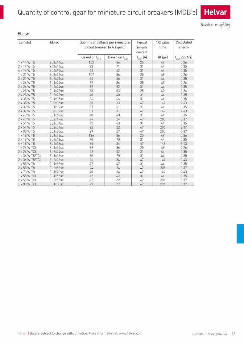
59Helvar | Data is subject to change without notice. More information at: www.helvar.com
Quantity of control gear for miniature circuit breakers (MCB’s) Quantity of control gear for miniature circuit breakers (MCB’s)
O07 089 1I 19.02.2014 3/6
EL-sc
Lamp(s) EL-sc Quantity of ballasts per miniature circuit breaker 16 A Type C
Typical inrush current
1/2 value time
Calculated energy
Based on ICont Based on Ipeak Ipeak (A) Δt (µs) Ipeak
2Δt (A2s)1 x 14 W T5 EL1x14sc 152 86 25 49 0.262 x 14 W T5 EL2x14sc 83 71 31 44 0.354 x 14 W T5 EL4x14sc 42 42 31 44 0.351 x 21 W T5 EL1x21sc 107 86 25 49 0.262 x 21 W T5 EL2x21sc 56 56 31 44 0.351 x 24 W T5 EL1x24sc 99 86 25 49 0.262 x 24 W T5 EL2x24sc 52 52 31 44 0.351 x 28 W T5 EL1x28sc 83 83 25 49 0.262 x 28 W T5 EL2x28sc 40 40 31 44 0.351 x 35 W T5 EL1x35sc 66 66 31 44 0.352 x 35 W T5 EL2x35sc 33 33 47 149 2.431 x 39 W T5 EL1x39sc 61 61 31 44 0.352 x 39 W T5 EL2x39sc 31 31 47 149 2.431 x 49 W T5 EL1x49sc 48 48 31 44 0.352 x 49 W T5 EL2x49sc 24 24 47 205 3.371 x 54 W T5 EL1x54sc 43 43 31 44 0.352 x 54 W T5 EL2x54sc 22 22 47 205 3.371 x 80 W T5 EL1x80sc 29 27 47 205 3.371 x 18 W T8 EL1x18sc 136 86 25 49 0.262 x 18 W T8 EL2x18sc 70 70 31 44 0.354 x 18 W T8 EL4x18sc 36 34 47 149 2.431 x 24 W TCL EL1x24sc 99 86 25 49 0.262 x 24 W TCL EL2x24sc 52 52 31 44 0.351 x 36 W T8/TCL EL1x36sc 70 70 31 44 0.352 x 36 W T8/TCL EL2x36sc 36 34 47 149 2.431 x 58 W T8 EL1x58sc 47 47 31 44 0.352 x 58 W T8 EL2x58sc 24 24 47 205 3.371 x 70 W T8 EL1x70sc 40 34 47 149 2.431 x 55 W TCL EL1x55sc 42 42 31 44 0.352 x 55 W TCL EL2x55sc 22 22 47 205 3.371 x 80 W TCL EL1x80sc 29 27 47 205 3.37

60 Helvar | Data is subject to change without notice. More information at: www.helvar.com
Quantity of control gear for miniature circuit breakers (MCB’s)
O07 089 1I 19.02.2014 4/6
EL-ngn5
Lamp(s) EL-ngn5 Quantity of ballasts per miniature circuit breaker 16 A Type C
Typical inrush current
1/2 value time
Calculated energy
Based on ICont Based on Ipeak Ipeak (A) Δt (µs) Ipeak
2Δt (A2s)1x14 W T5 EL1x14-35ngn5 161 88 21 139 0.042x14 W T5 EL2x14-35ngn5 83 50 34 152 0.133x14 W T5 EL3/4x14ngn5 56 50 34 149 1.34x14 W T5 EL3/4x14ngn5 42 50 34 149 1.34x14 W T5 EL4x14ngn5 41 50 34 152 0,131x21 W T5 EL1x14-35ngn5 112 88 21 139 0.042x21 W T5 EL2x14-35ngn5 57 50 34 152 0.131x24 W T5 EL1x24ngn5 101 88 21 136 0.042x24 W T5 EL2x24ngn5 53 80 22 142 0.053x24 W T5 EL3/4x24ngn5 35 33 47 165 2.674x24 W T5 EL3/4x24ngn5 27 33 47 165 2.671x28 W T5 EL1x14-35ngn5 86 88 21 139 0.042x28 W T5 EL2x14-35ngn5 43 50 34 152 0.131x35 W T5 EL1x14-35ngn5 68 88 21 139 0.042x35 W T5 EL2x14-35ngn5 34 50 34 152 0.131x36 W T5 EL1x39/36ngn5 70 88 21 136 0.042x36 W T5 EL2x39/36ngn5 37 50 34 152 0.131x39 W T5 EL1x39ngn5 60 88 21 136 0.042x39 W T5 EL2x39/36ngn5 32 50 34 152 0.131x49 W T5 EL1x49ngn5 47 57 23 183 0.072x49 W T5 EL2x49ngn5 25 33 40 183 0.221x54 W T5 EL1x54ngn5 44 80 23 141 0.052x54 W T5 EL2x54ngn5 22 26 40 230 0.271x55 W T5 EL1x55ngn5 43 57 23 183 0.072x55 W T5 EL2x55ngn5 22 26 40 230 0.271x80 W T5 EL1x80ngn5 30 45 36 156 0.152x80 W T5 EL2x80ngn5 15 16 49 287 0,40
EL-ngn
EL-es
Lamp(s) EL-ngn (T8) Quantity of ballasts per miniature circuit breaker
Typical inrush current
1/2 value time
Calculated energy
Based on power
consumptionBased on
inrush current Ipeak (A) Δt (µs) Ipeak2Δt (A2s)
C 16A C 16A1x18 EL1x18ngn 136 85 23 131 0,052x18 EL2x18ngn 70 87 22 132 0,054x18 EL4x18ngn 36 32 37 193 0,201x36 EL1x36ngn 72 80 24 134 0,062x36 EL2x36ngn 37 56 30 152 0,091x58 EL1x58ngn 47 84 23 128 0,052x58 EL2x58ngn 24 37 50 136 0,263x18 EL3/4x18ngn 50 50 34 149 0,134x18 EL3/4x18ngn 37 50 34 149 0,131x15 EL1x15ngn 152 88 21 139 0,041x30 EL1x30ngn 92 88 21 139 0,04
Lamp(s) EL-es (T8) Quantity of ballasts per miniature circuit breaker 16 A Type C
Typical peak inrush current Ipeak
[A]
1/2 value time rt
[µs]
Calculated energy
Ipeak2rt [A2s]
Based on power consumption
Based on inrush current
C 16A C 16A4x18 EL4x18es 35 60 29 148 0,092x36 EL2x36es 38 58 29 153 0,092x58 EL2x58es 24 29 37 215 0,21

61Helvar | Data is subject to change without notice. More information at: www.helvar.com
EL-s / EL-su
Lamp(s) EL-s EL-su Quantity of ballasts per miniature circuit breaker 16 A Type C
Typical inrush current
1/2 value time
Calculated energy
Based on ICont Based on Ipeak Ipeak (A) Δt (µs) Ipeak
2Δt (A2s)2 x 58 W T8 EL2x58s EL2x58s-u 24 24 47 165 2.671 x 70 W T8 EL1x70s - 40 40 34 149 1.302 x 70 W T8 EL2x70s - 20 20 49 180 3.17
Quantity of control gear for miniature circuit breakers (MCB’s)
O07 089 1I 19.02.2014 6/6
EL-TCs
Lamp(s) EL1/2x-TCs Quantity of ballasts per miniature circuit breaker 16 A Type C
Typical inrush current
1/2 value time
Calculated energy
Based on ICont Based on Ipeak Ipeak (A) Δt (µs) Ipeak
2Δt (A2s)1 x 9 W TC-SE 1/2x9-13TCs 229 34 41 182 0.231 x 10 W TC-DE 1/2x9-13TCs 224 34 41 182 0.231 x 10 W TC-DD 1/2x9-13TCs 215 34 41 182 0.231 x 11 W TC-SE 1/2x9-13TCs 167 34 41 182 0.231 x 13 W TC-DE/TE 1/2x9-13TCs 160 34 41 182 0.231 x 16 W TC-DD 1/2x9-13TCs 160 34 41 182 0.232 x 9 W TC-SE 1/2x9-13TCs 129 34 41 182 0.232 x 10 W TC-DE 1/2x9-13TCs 120 34 41 182 0.232 x 11 W TC-SE 1/2x9-13TCs 90 34 41 182 0.232 x 13 W TC-DE/TE 1/2x9-13TCs 84 34 41 182 0.231 x 18 W TC-DE/TE 1/2x18TCs 127 35 41 181 0.222 x 18 W TC-DE/TE 1/2x18TCs 67 35 41 181 0.221 x 21 W TC-DD 1/2x18TCs 102 35 41 181 0.221 x 18 W TC-L/F 1/2x18-42TCs 147 33 40 192 0.231 x 24 W TC-L/F 1/2x18-42TCs 96 33 40 192 0.231 x 26 W TC-DE/TE 1/2x18-42TCs 88 33 40 192 0.231 x 32 W TC-TE 1/2x18-42TCs 75 33 40 192 0.231 x 42 W TC-TE 1/2x18-42TCs 55 33 40 192 0.231 x 22 W TC-T5c 1/2x18-42TCs 96 33 40 192 0.231 x 40 W TC-T5c 1/2x18-42TCs 59 33 40 192 0.232 x 18 W TC-L/F 1/2x18-42TCs 68 33 40 192 0.232 x 24 W TC-L/F 1/2x18-42TCs 46 33 40 192 0.232 x 26 W TC-DE/TE 1/2x18-42TCs 42 33 40 192 0.232 x 26 W TC-DE/TE 2x32/42TCs 45 33 42 184 0.242 x 32 W TC-TE 2x32/42TCs 38 33 42 184 0.242 x 42 W TC-TE 2x32/42TCs 28 28 42 184 0.2422 + 40 W TC-T5c 2x32/42TCs 38 33 42 184 0.2440 + 40 W TC-T5c 2x32/42TCs 32 32 42 184 0.241x14W PL-R 1/2x14-17TCs 133 33 41 190 0.252x14W PL-R 1/2x14-17TCs 76 33 41 190 0.251x17W PL-R 1/2x14-17TCs 110 33 41 190 0.252x17W PL-R 1/2x14-17TCs 60 33 41 190 0.251x36TC-L 1/2x36/38TCs 63 33 42 184 0.242x36TC-L 1/2x36/38TCs 33 33 42 184 0.241x38TC-DD 1/2x36/38TCs 62 33 42 184 0.242x38TC-DD 1/2x36/38TCs 32 32 42 184 0.24

62 Helvar | Data is subject to change without notice. More information at: www.helvar.com
Wire release instructions
These instructions provide details of how to remove wires from the terminals of Helvar ballasts without damaging the terminals. Ensure mains supply is switched off before attempting any wire removal.
Magnetic BallastsElectronic Ballasts… with push in terminals Use a 1 mm² solid pin (or similar)
… with screw terminals Use a flat blade screwdriver
quick release vertical push-in terminalsUse a blunt tool (example shown) to push down gently on the built in push button.
EL-ngnUse a 1 mm² solid pin (or similar) or gently twist and pull wire at the same time
O13 100 1H 12.04.2011 1/1
IDC & horizontal push-in terminals)Gently twist and pull wire at the same time
… NK/E...SE & L26S types Use a flat blade screwdriver
Note: Removal using a solid pin is not advised since permanent damage to the connector may occur.
Note: Wire removal from insulation piercing contact is only possible with force.

63
T5
Helvar | Data is subject to change without notice. More information at: www.helvar.com
… with push in terminals Use a 1 mm² solid pin (or similar)
Helvar ballasts for fluorescent lamps
Lamp type W Length (mm)
Cap Standard electronic ballast Pa
ge Controllableelectronic ballast Pa
ge Digital DALIelectronic ballast Pa
ge Magnetic Ballast (230 V, 50 Hz) Pa
ge
T5
(FD-H)
ø16mm
4 136 G5 L 8 D L 8 DL 1) 38
6 212 G5 L 8 D L 8 DL 1) 38
8 288 G5 EL1/2x9-13TCs 2) - L 8 D L 11 D 38
13 517 G5 - L 13 DL 1) 38
14 549 G5
EL1x14-35ngn5EL2x14-35ngn5EL3/4x14ngn5EL4x14ngng5EL1/2x9-13TCs
20
27
EL1x14scEL2x14scEL4x14sc
10EL1x14-35iDimEL2x14-35iDimEL3x14iDimEL4x14iDim
6
21 849 G5EL1x14-35ngn5EL2x14-35ngn5EL1/2x9-13TCs
20
27EL1x21scEL2x21sc 10 EL1x14-35iDim
EL2x14-35iDim 6
24 549 G5EL1x24ngn5EL2x24ngn5EL3/4x24ngn5
20 EL1x24scEL2x24sc 10 EL1x24iDim
EL2x24iDim 6
28 1149 G5EL1x14-35ngn5EL2x14-35ngn5EL1/2x9-13TCs
20
27EL1x28scEL2x28sc 10 EL1x14-35iDim
EL2x14-35iDim 6
35 1449 G5 EL1x14-35ngn5EL2x14-35ngn5 20 EL1x35sc
EL2x35sc 10 EL1x14-35iDim EL2x14-35iDim 6
39 849 G5 EL1x39/36ngn5EL2x39/36ngn5 20 EL1x39sc
EL2x39sc 10 EL1x39iDim EL2x39iDim 6
49 1449 G5EL1x49ngn5EL2x49ngn5EL2x49ngn5-XL
20 EL1x49scEL2x49sc 10 EL1x49iDim
EL2x49iDim 6
54 1149 G5EL1x54ngn5EL2x54ngn5EL2x54ngn5-XL
20 EL1x54scEL2x54sc 10 EL1x54iDim
EL2x54iDim 6
80 1449 G5 EL1x80ngn5EL2x80ngn5
20 EL1x80sc 10 EL1x80iDimEL2x80iDim 6
Types printed BOLD are ENEC approved combinations. Other combinations mentioned are tested and recommended by Helvar.Please check CE compatibility and EEI classification from ballast datasheets.For information on compatibility with amalgam lamps, please contact your local Helvar representative.1) Approved to EN 61347-2-82) For a combination of two 8 W T5-lampsNote: All combinations can be used as well with Eco-lamps.
O13 095 1Q 19.02.2014 1/6

64
T8
Helvar | Data is subject to change without notice. More information at: www.helvar.com
Helvar ballasts for fluorescent lamps
Lamp type W Length (mm)
Cap Standard electronic ballast Pa
ge Controllableelectronic ballast Pa
ge Digital DALIelectronic ballast Pa
ge Magnetic Ballast (230 V, 50 Hz) Pa
ge
T8
(FD-E)
ø 26 mm18 590 G13
EL1x18efEL2x18efEL4x18efEL4x18es
EL1x18ngnEL2x18ngnEL3/4x18ngnEL4x18ngn
23
22
EL1x18scEL2x18scEL4x18sc
12 -
L 18 A-LL 18 A-KL 18 A-TL 2x18 A-LL 2x18 A-L
35
36 1200 G13
EL2x36esEL1x36efEL2x36ef
EL1x36ngnEL2x36ngnEL1x18-42TCs
23
22
EL1x36scEL2x36sc 12 EL1x36iDim
EL2x36iDim 8
L 36 A-TL 36 A-KL 40 A-CL 36 LUA
35
58 1500 G13
EL2x58esEL1x58ef
EL1x58ngnEL2x58ngn
23
22
EL1x58scEL2x58sc 12 -
L 65 A-PL 58 A-KL 58 A-TL 58 LUA
35
70 1500 G13 EL1x70sEL2x70s 23 EL1x70sc 12 - L 75 A-S 2)
L 75 LUA 35
15 450 G13 - - - L 15 AL 15 A-P 35
16 720 G13 - - - L 16 DL 16 DL 35
23 970 G13 - - L 15 A-P 35
30 900 G13 EL2x32/42TCs 27 - L 30 AL 30 A-P 35
38 1047 G13 - EL1x36scEL2x36sc - -
L 36 A-KL 36 A-TL 36 LUAL 40 A-C
35
Types printed BOLD are ENEC approved combinations. Other combinations mentioned are tested and recommended by Helvar.Please check CE compatibility and EEI classification from ballast datasheets.1) Approved to EN 61347-2-82) 240 V, 50 Hz3) Not T8 eco lamp
O13 095 1R 20.01.2016 2/6

65Helvar | Data is subject to change without notice. More information at: www.helvar.com
Helvar ballasts for fluorescent lamps
Lamp type W Cap Standard electronic ballast Pa
ge Controllableelectronic ballast Pa
ge Digital DALIelectronic ballast Pa
ge Magnetic Ballast (230 V, 50 Hz) Pa
ge
T5 circular 22 2GX13 EL1/2x18-42TCs 27 EL1/2x18/24iDim-c 9
40 2GX13 EL1/2x18-42TCsEL2x32/42TCs1) 27 EL1x39sc
EL2x39sc13- EL1/2x18/24iDim-c 9
55 2GX13 EL1x55ngn5 - EL1x55sc -
Circline(FD-E)
22 G10q L 30 A 3832 G10q
40 G10qL 36 A-KL 36 A-TL 36 LUAL 40 A-C
-
Mod-U-line(FU-E)
40 G13 -
L 36 LUAL 40 A-CL 36 A-KL 36 A-T
-
TC-DD 2D-lamp GR8, for magnetic ballast only GR10q, for electronic ballast or magnetic with external starter
10 GR10q EL1/2x9-13TCs 27
16 GR8, GR10q EL1/2x9-13TCs 27 L 16 D 2)
L 16 DL 38
21 GR8, GR10q EL1/2x18-42TCs
28 GR8, GR10q EL1/2x18-42TCs 27
L 18 A-LL 18 A-TL 18 A-KL 26S
38
38 GR8, GR10q EL1/2x36/38TCs 27
L 36 LUAL 40 A-CL 36 A-KL 36 A-T
38
Types printed BOLD are ENEC approved combinations. Other combinations mentioned are tested and recommended by Helvar.Please check CE compatibility and EEI classification from ballast datasheets.For information on compatibility with amalgam lamps, please contact your local Helvar representative.1) For a combination of one 22 W and one 40 W circular lamp2) GR8 not ENEC approved
O13 095 1Q 19.02.2014 3/6

66 Helvar | Data is subject to change without notice. More information at: www.helvar.com
Helvar ballasts for fluorescent lamps
Lamp type W Cap Standard electronic ballast Pa
ge Controllableelectronic ballast Pa
ge Digital DALIelectronic ballast Pa
ge Magnetic Ballast (230 V, 50 Hz) Pa
ge
TC-L(FSD-E)
18 2G11 EL1/2x18-42TCs
EL1x36/40/18s
26
25- EL1/2x18/24iDim-c 9
L18 A-K L18 A-T L18 A-L
37
24 2G11
EL1/2x18-42TCs
EL1x24ngn5 EL2x24ngn5 EL3/4x24xngn5
26
24 EL1x24scEL2x24sc 13
EL1x24iDimEL2x24iDim
EL1/2x18/24iDim-c
8
9
L18 A-K L18 A-T L18 A-L
37
26 2GX11 EL1x14-35iDim 1)
EL2x14-35iDim 1) 8
28 2GX11 EL1x14-35iDim 1)
EL2x14-35iDim 1) 8
36 2G11
EL1x39/36ngn5EL2x39/36ngn5 EL1/2x36/38TCsEL1/2x18-42TCsEL2x36ngn
24
2826-
EL1x36scEL2x36sc 13 EL1x36iDim
EL2x36iDim8
L 36 LUA L 40 A-C L 36 A-T L 36 A-K
37
40 2G11 EL1/2x18-42TCs 26EL1x39scEL2x39sc 13 EL1x39iDim
EL2x39iDim 8
55 2G11 EL1x55ngn5EL2x55ngn5 24 EL1x55sc
EL2x55sc13 EL1x55iDim
EL2x55iDim 8
80 2G11 EL1x80ngn5EL2x80ngn5 24 EL1x80sc 13 EL1x80iDim
EL2x80iDim 8
Types printed BOLD are ENEC approved combinations. Other combinations mentioned are tested and recommended by Helvar.Please check CE compatibility and EEI classification from ballast datasheets.For information on compatibility with amalgam lamps, please contact your local Helvar representative.1) To ensure stable operation of the lamp it is not recommended to dim the light level below 3 %
O13 095 1Q 19.02.2014 4/6

67Helvar | Data is subject to change without notice. More information at: www.helvar.com
Helvar ballasts for fluorescent lamps
Lamp type ILCOS W Cap Standard electronic ballast Pa
ge Controllable electronic ballast Pa
ge Digital DALIelectronic ballast Pa
ge Magnetic Ballast (230 V, 50 Hz) Pa
ge
TC-F
FSS-E
18 2G10 EL1/2x18-42TCs 26 EL1/2x18/24iDim-c 9
L 18 A-LL 18 A-KL 18 A-T
-
24 2G10 EL1/2x18-42TCs 26 EL1x24sc EL2x24sc 13 EL1/2x18/24iDim-c 9
L 18 A-LL 18 A-TL 18 A-K
-
36 2G10EL1/2x36/38TCsEL1/2x18-42TCsEL1x39/36ngn5EL2x39/36ngn5
2626-
EL1x36scEL2x36sc 13 EL1x36iDim
EL2x36iDim -L 36 A-KL 36 LUAL 40 A-C
-
TC-S
FSD-I
5 G23 L 11 D 37
7 G23 L 11 D 37
9 G23 L 11 D 37
11 G23 L 11 D 37
TC-SE
FSD-E
9 2G7 EL1/2x9-13TCs 26
11 2G7 EL1/2x9-13TCs 26
TC-D
FSQ-I
10 G24d-1 L 13 DL13 DL 1) 38
13 G24d-1 L13 DL13 DL 1) 38
18 G24d-2 L18 DL18 DL 38
26 G24d-3
L26 S-100mmL18 A-LL18 A-KL18 A-T
38
Types printed BOLD are ENEC approved combinations. Other combinations mentioned are tested and recommended by Helvar.Please check CE compatibility and EEI classification from ballast datasheets.For information on compatibility with amalgam lamps, please contact your local Helvar representative.1) Approved to EN61347-2-8
O13 095 1R 20.01.2016 5/6

68 Helvar | Data is subject to change without notice. More information at: www.helvar.com
Helvar ballasts for fluorescent lamps
Lamp type ILCOS W Cap Standard electronic ballast Pa
ge Controllable electronic ballast Pa
ge Digital DALIelectronic ballast Pa
ge Magnetic Ballast (230 V, 50 Hz) Pa
ge
TC-DE
FSQ-E
10 G24q-1 EL1/2x9-13TCs 28
13 G24q-1 EL1/2x9-13TCs 28
18 G24q-2 EL1/2x18TCs 28 EL1/2x18iDim-c 9
26 G24q-3 EL1/2x18-42TCsEL2x32/42TCs 28 EL1/2x26-42iDim-c
EL2x26-42iDim-c 9
TC-T
FSM-I
18 GX24d-2 L18 D -
26 GX24d-3 L18 TL2 L18 TL3
--
TC-TE
FSM-E
13 GX24q-1 EL1/2x9-13TCs 28
18 GX24q-2 EL1/2x18TCs 28 EL1/2x18iDim-c 9
26 GX24q-3 EL1/2x18-42TCsEL2x32/42TCs 28 EL1/2x26-42iDim-c
EL2x26-42iDim-c 9
32 GX24q-3 EL1/2x18-42TCsEL2x32/42TCs 28 EL1/2x26-42iDim-c
EL2x26-42iDim-c 9
42 GX24q-4 EL1/2x18-42TCsEL2x32/42TCs 28 EL1/2x26-42iDim-c
EL2x26-42iDim-c 9
57 GX24q-4 EL1/2x18-42TCs 28 EL1/2x26-42iDim-c 2) 9
PL-R 14 GR14q-1 EL1/2x14/17TCs 27
17 GR14q-1 EL1/2x14/17TCs 27
Types printed BOLD are ENEC approved combinations. Other combinations mentioned are tested and recommended by Helvar.Please check CE compatibility and EEI classification from ballast datasheets.1) Approved to EN61347-2-82) UIN > 220 V , Ta > 18 OCFor information on compatibility with amalgam lamps, please contact your local Helvar representative.
O13 095 1R 20.01.201 6/6

www.helvar.com
REF
MAC
24
015
1A
Eng
lish
22.0
2.20
16
Helvar has representatives all over the world.For additional information, please visit www.helvar.com
Due to a policy of continuous improvement, Helvar reserve the right to alter specifications without notice at anytime.