band crawler & stainless steel band parts and … crawler parts and operati… · • never...
TRANSCRIPT

WHERE THERE’S PIPE, THERE’S MATHEY P. O. Box 472110, Tulsa, OK 74147-2110 USA
Toll Free: 800-725-7311 / 918-447-1288 Office 918-447-0188 Fax www.mathey.com
Band Crawler & Stainless Steel Band Parts and Operating Manual
Part Number: 05-0116-009, 05-0116-014, 05-0116-S01
For Future reference, Record your Band Crawler serial numbers here
Serial #___________ Manual _____ Motorized ______
REVISED: July 27, 2016 ©Mathey Dearman, Inc.

2
Table of Contents Section Description Page 1.0 SAFETY …………………………………………………………………………………………………………………………… 3 2.0 GENERAL INFORMATION ……………………………………………………………………………………………….. 7 Figure 1 Clearance around Pipe …………………………………………………………………………………………………… 7 3.0 CRAWLER ACCESSORIES AND BAND CHART …………………………………………………………………… 8 Table 1 Band Crawler and Accessories ……………………………………………………………………………………….. 9 Table 2 Band Selection Chart ……………………………………………………………………………………………………… 10 4.0 OPERATION SUMMARY .…………………………………………………………………………………………………. 10 4.1 Manual Band Crawler (description) ………………………………………………………………………………… 10 4.2 Motorized Band Crawler (description) ……………………………………………………………………………. 10 5.0 SET-UP ……………………………………………………………………………………………………………………………. 11 5.1 Installation of the Stainless Steel Band on Pipe ………………………………………………………………. 11 Figure 2 Band Parts Configuration ……………………..………………………………………………………………………… 11 Table 3 Band Parts Identification …………………………………………….…………………………………………………. 11 Picture 1 Closing of Band Latch ……………………………………………………………………………………………………… 12 5.2 Installation of the Manual Band Crawler on the Band …………………………………………………….. 12 Picture 2 Relationship of the Grooved Wheel to Stainless Steel Band Radius ………………………………… 13 5.3 Installation of the Motorized Band Crawler on the Band ……………………………………………….. 13 Picture 3 Motor Control Box Face View …………………………………………………………………………………………. 14 Picture 4 Motor Control Box End View ………………………………………………………………………………………….. 14 Picture 5 Cable, Motor Control Box to Motor Assembly ………………………………………………………………… 14 Figure 3 Tip Clearance Illustration ………………………………………………………………………………..……………… 15 5.4 Installation of the Torch in the Manual or Motorized Band Crawler ……………….……………… 15 5.5 The Manual Cutting Process …………………………………………………………………………………………… 15 5.6 The Motorized Cutting Process ………………………………………………………………………………………. 16 Figure 4 Manual Band Crawler Parts Configuration ……………………………………………………………………… 18 Table 4 Manual Band Crawler Parts Identification ………………………………………………………………………. 19 Figure 5 Motorized Band Crawler Parts Configuration …………………………………………………………………. 20 Table 5 Motorized Band Crawler Parts Identification ………………………………………………………………….. 21 6.0 MAINTENANCE ………………………………………………………………………………………………………………. 21 6.1 Band Crawler Maintenance …………………………………………………………………………………………….. 21 6.2 Wheel Spring Tension Adjustment ………………………………………………………………………………….. 21 6.3 Installation of the Stepper Motor Kit ……………………………………………………………………………… 22 6.4 Storage …………………………………………………………………………………………………………………………… 22 6.5 Stainless Steel Band Maintenance ………………………………………………………………………………….. 22 7.0 LIMITATIONS ………………………………………………………………………………………………………………….. 22 8.0 MACHINE SAFETY …………………………………………………………………………………………………………… 23 9.0 CONDITION OF USE ……………………………………………………………………………………………………….. 23 9.1 Condition of Use …………………………………………………………………………………………………………….. 23 9.2 Use of Band and Band Crawler not allowed by Manufacturer ………………………………………… 23 10.0 DISPOSAL OF THE BAND AND BAND CRAWLER ………………………………………………………………. 23 10.1 General Information ………………………………………………………………………………………………………. 23 10.2 Composition of Major Components ……………………………………………………………………………….. 23 11.0 Warranty ……………………………………………………………………………………………………………………….. 23 Table 6 Trouble Shooting ……………………………………………………………………………………………………………. 24
For the latest news, accessories and information about Mathey Dearman products visit: www.mathey.com

3
1.0 SAFETY
ELECTRIC SHOCK CAN KILL Electric Shock can injure or kill. Saddle machine operation and many cutting processes use or produce high voltage electrical energy. This electric energy can cause severe or fatal shock to the operator or others in the work place. • Never touch any parts that are electrically “live” or “hot” • Wear dry gloves and clothing. Insulate yourself from the work piece or other parts of the plasma cutting circuit. • Repair or replace all worn or damaged parts. • Extra care must be taken when work place is moist or damp. • If installing a motorized saddle machine, install and maintain equipment according to NEC (National Electric Code), refer to
publications section in this manual. • Disconnect power source before performing any service or repairs. • Read and follow all the instructions in the operating manuals.
FIRE AND EXPLOSION Hot slag, sparks, oxygen-fueled cutting flame or the plasma arc can cause fire and explosion. • Be sure there are no combustible or flammable materials in the workplace. Any material that cannot be removed must be
protected. • Ventilate all flammable or explosive vapors from the workplace. • Do not cut or weld on containers that may have held combustibles. • Provide a fire watch when working in an area where fire hazards may exist.
AUTOMATIC OPERATION The Saddle Machine may operate automatically without warning. Keep the immediate area around the Saddle Machine clear of materials that may cause interference. Keep area clear of bystanders. All untrained persons should not work on or near a saddle machine. Do not leave the saddle machine unattended while power is on to any electronics.
NOISE Noise can cause permanent hearing loss. Plasma arc cutting, oxy/fuel torch cutting, and grinding can cause noise levels that exceed safe limits. You must protect your ears from loud noise to prevent permanent loss of hearing. • To protect your hearing from loud noise, wear protective earplugs and/or ear muffs. Protect others in the workplace. • Noise levels should be measured to be sure the decibels (sound) do not exceed safe levels. • For information on how to test for noise refer to the publications section of this manual
GASES, DUST, AND FUMES Gases and fumes produced during the cutting process can be dangerous to your health. • Keep all fumes and gases away from the breathing area. Keep your head out of the cutting fume plume. • Use an air-supplied respirator if ventilation is not adequate to remove all fumes and gases. • The kinds of fumes and gases from cutting depend on the kind of metal being cut, coatings on the metal, and the different
processes. You must be very careful when cutting or welding any metals which may contain the following: Antimony Cadmium Lead Selenium
Arsenic Chromium Manganese Silver Barium Cobalt Mercury Vanadium Beryllium Copper Nickel
4
Always read the Material Safety Data Sheet (MSDS) supplied with the material you are cutting. The MSDS will give you the information regarding the kind and amount of fumes and gases that may be produced from cutting and those that may be dangerous to your health • For information on how to test for fumes and gases in your workplace refer to publications section of this manual. • Use special equipment, if needed, to capture fumes and gases. • Do not use in an area where combustible or explosive gases or materials are located. • Phosgene, a toxic gas, is generated from the vapors of chlorinated solvents and cleansers. Remove all sources of these vapors. • This product, when used for welding or cutting, produces fumes or gases which contain chemicals known to the State of
California to cause birth defects and, in some cases, cancer. (California Health & Safety Code Sec. 25249.5 et seq.) • Some dust created by cutting, grinding, drilling, and other construction activities contains chemicals known to cause cancer,
birth defects or other reproductive harm. Some examples of these chemicals are: • Lead from lead-based paint. • Crystalline silica from bricks and cement and other masonry products. • Arsenic and chromium from chemically-treated lumber (CCA).
• Your risk from these exposures varies, depending on how often you do this type of work. To reduce your exposure to these chemicals: work in a well-ventilated area, and work with approved safety equipment, such as those dust masks that are specially designed to filter out microscopic particles.
• Avoid prolonged contact with dust from cutting, grinding, drilling, and other construction activities. Wear protective clothing and wash exposed areas with soap and water. Allowing dust to get into your mouth, eyes, or lay on the skin may promote absorption of harmful chemicals.
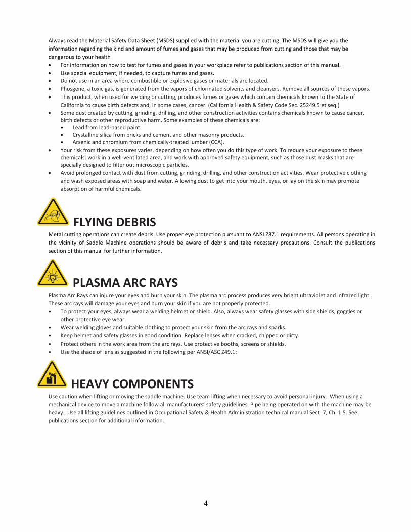
FLYING DEBRIS Metal cutting operations can create debris. Use proper eye protection pursuant to ANSI Z87.1 requirements. All persons operating in the vicinity of Saddle Machine operations should be aware of debris and take necessary precautions. Consult the publications section of this manual for further information.
PLASMA ARC RAYS Plasma Arc Rays can injure your eyes and burn your skin. The plasma arc process produces very bright ultraviolet and infrared light. These arc rays will damage your eyes and burn your skin if you are not properly protected. • To protect your eyes, always wear a welding helmet or shield. Also, always wear safety glasses with side shields, goggles or
other protective eye wear. • Wear welding gloves and suitable clothing to protect your skin from the arc rays and sparks. • Keep helmet and safety glasses in good condition. Replace lenses when cracked, chipped or dirty. • Protect others in the work area from the arc rays. Use protective booths, screens or shields. • Use the shade of lens as suggested in the following per ANSI/ASC Z49.1:
HEAVY COMPONENTS Use caution when lifting or moving the saddle machine. Use team lifting when necessary to avoid personal injury. When using a mechanical device to move a machine follow all manufacturers’ safety guidelines. Pipe being operated on with the machine may be heavy. Use all lifting guidelines outlined in Occupational Safety & Health Administration technical manual Sect. 7, Ch. 1.5. See publications section for additional information.

5
ELECTRIC AND MAGNETIC FIELDS Electric current flowing through any conductor causes localized Electric and Magnetic Fields (EMF). Welding and plasma cutting current creates EMF fields around cables and machines. EMF fields may interfere with some pacemakers, and operators and observers having a pacemaker should consult their physician before operation. Exposure to EMF fields may also have other health effects which are now not known.
PINCH AND CRUSH POINTS Mathey Dearman Saddle Machines in motion can create pinch points in normal operation. Be aware of all areas that may potentially be a hazard when the Saddle Machine is in motion. Avoid working on the machine while the control electronics are energized. Saddle machines may use hard stops as part of normal setup, while in motion these stops may be contacted creating a crush point. Do not allow hoses, cords or other nearby items to come in contact with the machine.
HOT MATERIALS The process of plasma cutting creates an arc of electricity that can be up to 45,000°F (25,000°C). Oxygen-fuel cutting flame can be up to 6,330°F (3,500°C). As a result, cut materials will be very hot after cutting. Use extreme care when handling recently cut materials. Proper protective apparel such as protective gloves should be worn when handling recently cut material. Material handling devices should also be considered. It is recommended to allow material to cool completely before handling.
MECHANICAL DRIVES Mechanical drives are in use while the CNC Saddle Machine is in operation. These drives use gears, chains, and drive screws. These components can move at high speed. Do not attempt to service, adjust, or otherwise touch these components while the machine is on. Secure loose articles of clothing and cables to prevent entanglement.
AIR LINES UNDER PRESSURE Certain tools and equipment use compressed air lines to operate. These air lines are under pressure. Hot sparks or flying debris may cause damage to these lines. Ensure that the air lines are kept free of punctures, burns, or other damage or defects that could cause failure. Inspect air lines periodically and repair or replace damaged lines.

6
PUBLICATIONS Refer to the following standards or their latest revisions for more information: • OSHA, SAFETY AND HEALTH STANDARDS, 29CFR 1910, obtainable from the Superintendent of Documents, U.S. Government
Printing Office, Washington, D.C. 20402
• ANSI Standard Z49.1, SAFETY IN WELDING AND CUTTING, obtainable from the American Welding Society, 550 N.W. Lejeune Rd, Miami, FL 33126
• NIOSH, SAFETY AND HEALTH IN ARC WELDING AND GAS WELDING AND CUTTING, obtainable from the Superintendent of Documents, U.S. Government Printing Office, Washington, D.C. 20402
• ANSI Standard Z87.1, SAFE PRACTICES FOR OCCUPATION AND EDUCATIONAL EYE AND FACE PROTECTION, obtainable from American National Standards Institute, 1430 Broadway, New York, NY 10018
• ANSI Standard Z49.2, FIRE PREVENTION IN THE USE OF CUTTING AND WELDING PROCESSES, obtainable from American National Standards Institute, 1430 Broadway, New York, NY 10018
• AWS Standard A6.0, WELDING AND CUTTING CONTAINERS WHICH HAVE HELD COMBUSTIBLES, obtainable from American Welding
Society, 550 N.W. Lejeune Rd, Miami, FL 33126
• NFPA Standard 51, OXYGEN-FUEL GAS SYSTEMS FOR WELDING, CUTTING AND ALLIED PROCESSES, obtainable from the National Fire Protection Association, Batterymarch Park, Quincy, MA 02269
• NFPA Standard 70, NATIONAL ELECTRICAL CODE, obtainable from the National Fire Protection Association, Batterymarch Park,
Quincy, MA 02269
• NFPA Standard 51B, CUTTING AND WELDING PROCESSES, obtainable from the National Fire Protection Association, Batterymarch Park, Quincy, MA 02269
• CGA Pamphlet P-1, SAFE HANDLING OF COMPRESSED GASES IN CYLINDERS, obtainable from the Compressed Gas Association, 1235
Jefferson Davis Highway, Suite 501, Arlington, VA 22202
• CSA Standard W117.2, CODE FOR SAFETY IN WELDING AND CUTTING, obtainable from the Canadian Standards Association, Standards Sales, 178 Rexdale Boulevard, Rexdale, Ontario, Canada M9W 1R3
• NWSA booklet, WELDING SAFETY BIBLIOGRAPHY obtainable from the National Welding Supply Association, 1900 Arch Street,
Philadelphia, PA 19103
• ANSI Standard Z88.2, PRACTICE FOR RESPIRATORY PROTECTION, obtainable from American National Standards Institute, 1430 Broadway, New York, NY 10018
IN ADDITION TO THE ABOVE INSTRUCTION, ALL SHOP, NATIONAL AND MANUFACTURER’S SAFETY INSTRUCTION CONCERNING THE FLAME CUTTING SYSTEM SHOULD BE FOLLOWED. ALL CUTTING OPERATIONS SHOULD BE CONDUCTED IN THE BEST OF SAFETY CONDITIONS.
7
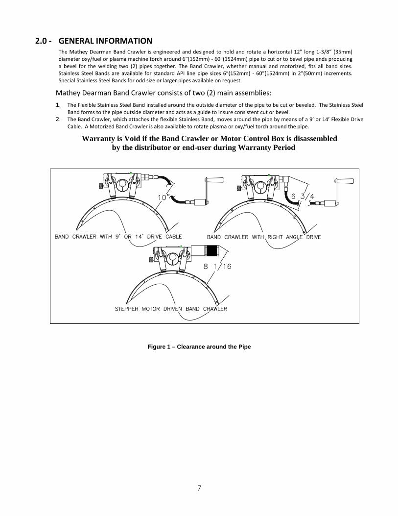
2.0 - GENERAL INFORMATION The Mathey Dearman Band Crawler is engineered and designed to hold and rotate a horizontal 12” long 1-3/8” (35mm) diameter oxy/fuel or plasma machine torch around 6”(152mm) - 60”(1524mm) pipe to cut or to bevel pipe ends producing a bevel for the welding two (2) pipes together. The Band Crawler, whether manual and motorized, fits all band sizes. Stainless Steel Bands are available for standard API line pipe sizes 6”(152mm) - 60”(1524mm) in 2”(50mm) increments. Special Stainless Steel Bands for odd size or larger pipes available on request.
Mathey Dearman Band Crawler consists of two (2) main assemblies: 1. The Flexible Stainless Steel Band installed around the outside diameter of the pipe to be cut or beveled. The Stainless Steel
Band forms to the pipe outside diameter and acts as a guide to insure consistent cut or bevel. 2. The Band Crawler, which attaches the flexible Stainless Band, moves around the pipe by means of a 9’ or 14’ Flexible Drive
Cable. A Motorized Band Crawler is also available to rotate plasma or oxy/fuel torch around the pipe.
Warranty is Void if the Band Crawler or Motor Control Box is disassembled by the distributor or end-user during Warranty Period
Figure 1 – Clearance around the Pipe
8
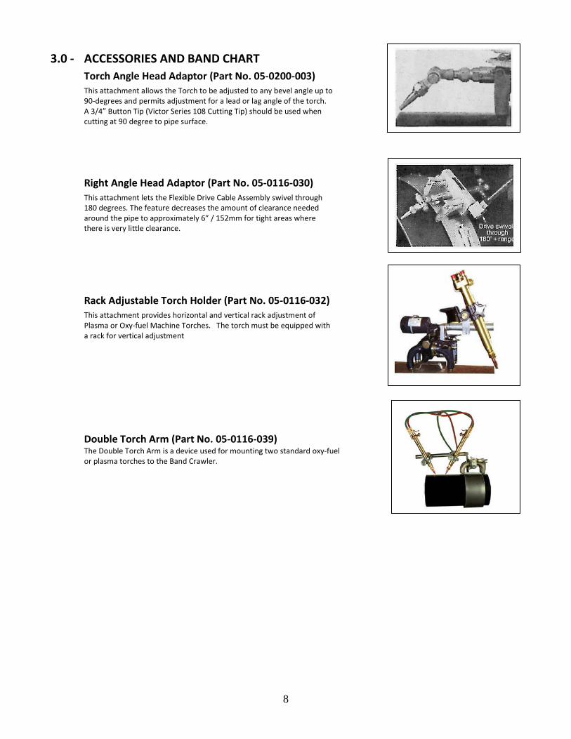
3.0 - ACCESSORIES AND BAND CHART Torch Angle Head Adaptor (Part No. 05-0200-003) This attachment allows the Torch to be adjusted to any bevel angle up to 90-degrees and permits adjustment for a lead or lag angle of the torch. A 3/4” Button Tip (Victor Series 108 Cutting Tip) should be used when cutting at 90 degree to pipe surface.
Right Angle Head Adaptor (Part No. 05-0116-030) This attachment lets the Flexible Drive Cable Assembly swivel through 180 degrees. The feature decreases the amount of clearance needed around the pipe to approximately 6” / 152mm for tight areas where there is very little clearance.
Rack Adjustable Torch Holder (Part No. 05-0116-032) This attachment provides horizontal and vertical rack adjustment of Plasma or Oxy-fuel Machine Torches. The torch must be equipped with a rack for vertical adjustment
Double Torch Arm (Part No. 05-0116-039) The Double Torch Arm is a device used for mounting two standard oxy-fuel or plasma torches to the Band Crawler.

9
Table 1 – Band Crawler and Accessories
Description Part Number
Band Crawler with 9’ / 2.7m Flex Drive Cable 05-0116-009
Band Crawler with 14’/ 4.3m Flex Drive Cable 05-0116-014
Right Angle Drive Adaptor (for Flex Driver Cable) 05-0116-030
Motorized Band Crawler, 90 – 240 vac 05-0116-S01
Motorizing Kit 05-0116-SA1
Rack Adjustable Torch Arm 05-0116-032
Double Torch Arm 05-0116-039
Victor MT210A Machine Torch 05-0200-002
Victor BHA Torch Angle Adaptor 05-0200-003
Victor 3”/76mm long Acetylene Cutting Tip, 3/4” / 19 cap. 05-0201-001
Victor 3”/76mm long Acetylene Cutting Tip, 1”/25mm cap. 05-0201-002
Victor 3/4”/19mm long Acetylene Cutting Button Tip, 3/4” / 19 Cap. 05-0201-003
Victor 3/4”/19mm long. Acetylene Cutting Button Tip, 1”/ 25mm Cap 05-0201-004
Victor 3”/76mm long Propane Cutting Tip, 3/4” / 19 cap. 05-0201-013
Victor 3”/76mm long Propane 3”/76mm long Cutting Tip, 1”/25mm cap. 05-0201-014
NOTE 1: A 3/4" cutting tip for Propane gas is not available NOTE 2: The use of a machine torch with a torch barrel shorter than 10” / 254mm is not recommended.

10
Table 2 – Stainless Steel Band Selector Chart
NOTE: Intermediate and larger size bands are available on special order.
4.0 - OPERATION SUMMARY 4.1 Manual Band Crawler
Manual operation of the Band Crawler is controlled by rotating the Crank Handle of the 9’ / 2.7m or 14’/ 4.3m Flexible Drive Cable Assembly. It can be turned in either direction, for either clockwise or counterclockwise rotation of Band Crawler around the Stainless Steel Band that is mounted to the pipe.
4.2 Motorized Band Crawler The Stepper Motor driven Band Crawler will operate on voltages 90 - 240 vac model. The Directional Control Switch on Motor Control Box determines clockwise and counterclockwise rotation of Band Crawler around the pipe. The Speed Control Switch controls speed of rotation around the pipe. The Motor Control Box is equipped with Emergency Stop.
WARNING: Motor control box is designed for use with single phase 90 – 240 volts alternating current (AC). Use of a higher current will result in serious injury or death.
Pipe Size Latch Type Standard
Inches mm 6 152 05-0104-006
8 203 05-0104-008
10 254 05-0104-010
12 304 05-0104-012
14 356 05-0104-014
16 406 05-0104-016
18 457 05-0104-018
20 508 05-0104-020
22 559 05-0104-022
24 610 05-0104-024
26 660 05-0104-026
28 711 05-0104-028
30 762 05-0104-030
32 813 05-0104-032
34 864 05-0104-034
36 914 05-0104-036
38 965 05-0104-038
40 1016 05-0104-040
42 1067 05-0104-042
44 1118 05-0104-044
46 1168 05-0104-046
48 1219 05-0104-048
50 1270 05-0104-050
52 1321 05-0104-052
54 1372 05-0104-054
56 1422 05-0104-056
58 1473 05-0101-058
60 1524 05-0104-060
11
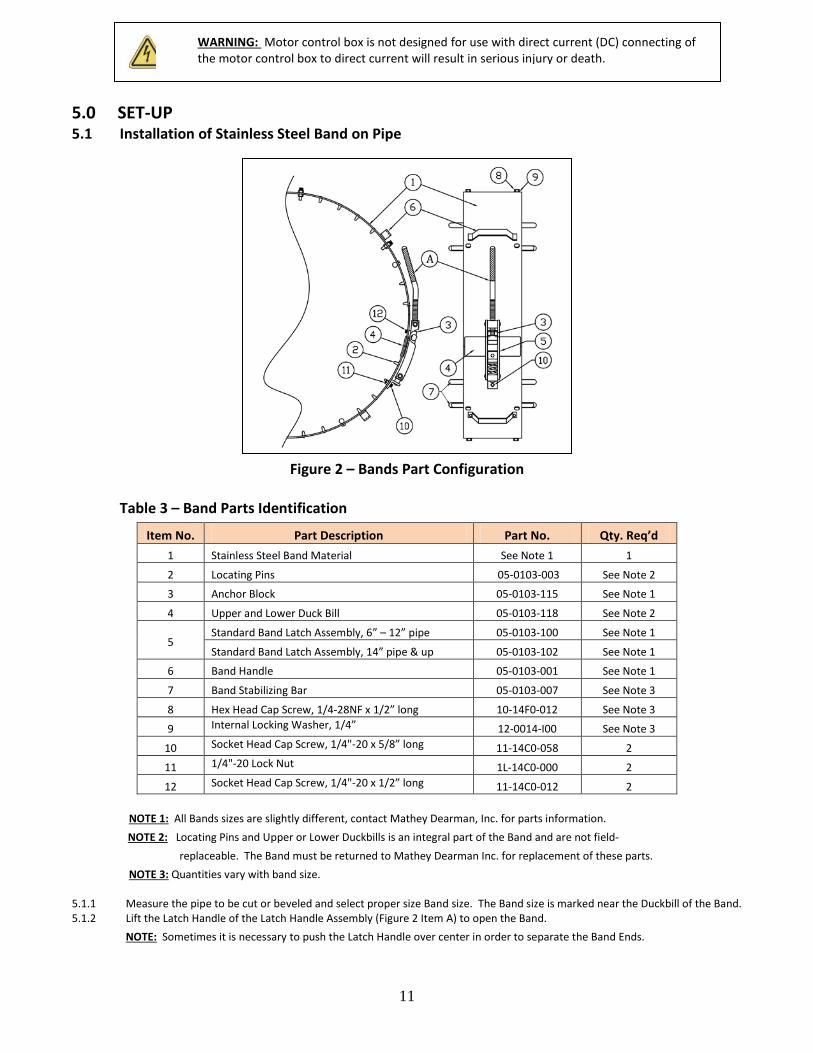
5.0 SET-UP 5.1 Installation of Stainless Steel Band on Pipe
Figure 2 – Bands Part Configuration Table 3 – Band Parts Identification
NOTE 1: All Bands sizes are slightly different, contact Mathey Dearman, Inc. for parts information.
NOTE 2: Locating Pins and Upper or Lower Duckbills is an integral part of the Band and are not field- replaceable. The Band must be returned to Mathey Dearman Inc. for replacement of these parts.
NOTE 3: Quantities vary with band size. 5.1.1 Measure the pipe to be cut or beveled and select proper size Band size. The Band size is marked near the Duckbill of the Band. 5.1.2 Lift the Latch Handle of the Latch Handle Assembly (Figure 2 Item A) to open the Band.
NOTE: Sometimes it is necessary to push the Latch Handle over center in order to separate the Band Ends.
Item No. Part Description Part No. Qty. Req’d 1 Stainless Steel Band Material See Note 1 1
2 Locating Pins 05-0103-003 See Note 2
3 Anchor Block 05-0103-115 See Note 1
4 Upper and Lower Duck Bill 05-0103-118 See Note 2
5 Standard Band Latch Assembly, 6” – 12” pipe 05-0103-100 See Note 1
Standard Band Latch Assembly, 14” pipe & up 05-0103-102 See Note 1
6 Band Handle 05-0103-001 See Note 1
7 Band Stabilizing Bar 05-0103-007 See Note 3
8 Hex Head Cap Screw, 1/4-28NF x 1/2” long 10-14F0-012 See Note 3
9 Internal Locking Washer, 1/4” 12-0014-I00 See Note 3
10 Socket Head Cap Screw, 1/4"-20 x 5/8” long 11-14C0-058 2
11 1/4"-20 Lock Nut 1L-14C0-000 2
12 Socket Head Cap Screw, 1/4"-20 x 1/2” long 11-14C0-012 2
WARNING: Motor control box is not designed for use with direct current (DC) connecting of the motor control box to direct current will result in serious injury or death.
12
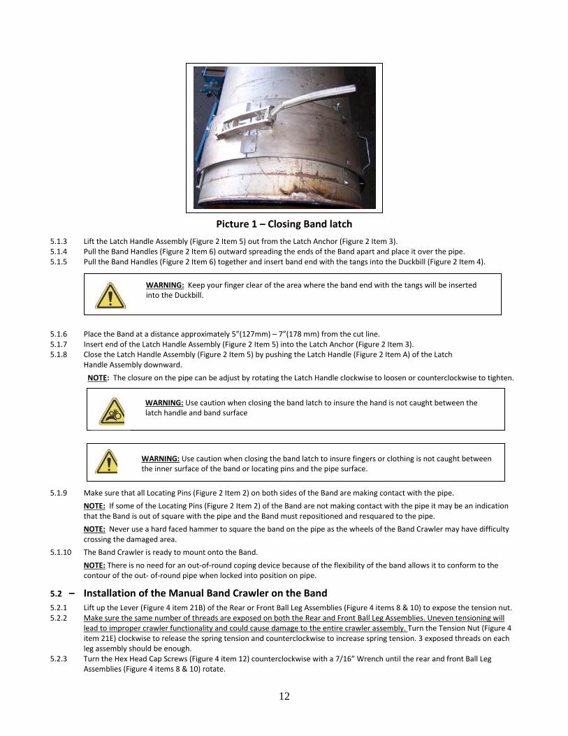
Picture 1 – Closing Band latch 5.1.3 Lift the Latch Handle Assembly (Figure 2 Item 5) out from the Latch Anchor (Figure 2 Item 3). 5.1.4 Pull the Band Handles (Figure 2 Item 6) outward spreading the ends of the Band apart and place it over the pipe. 5.1.5 Pull the Band Handles (Figure 2 Item 6) together and insert band end with the tangs into the Duckbill (Figure 2 Item 4).
5.1.6 Place the Band at a distance approximately 5”(127mm) – 7”(178 mm) from the cut line. 5.1.7 Insert end of the Latch Handle Assembly (Figure 2 Item 5) into the Latch Anchor (Figure 2 Item 3). 5.1.8 Close the Latch Handle Assembly (Figure 2 Item 5) by pushing the Latch Handle (Figure 2 Item A) of the Latch
Handle Assembly downward. NOTE: The closure on the pipe can be adjust by rotating the Latch Handle clockwise to loosen or counterclockwise to tighten.
5.1.9 Make sure that all Locating Pins (Figure 2 Item 2) on both sides of the Band are making contact with the pipe. NOTE: If some of the Locating Pins (Figure 2 Item 2) of the Band are not making contact with the pipe it may be an indication that the Band is out of square with the pipe and the Band must repositioned and resquared to the pipe. NOTE: Never use a hard faced hammer to square the band on the pipe as the wheels of the Band Crawler may have difficulty crossing the damaged area.
5.1.10 The Band Crawler is ready to mount onto the Band. NOTE: There is no need for an out-of-round coping device because of the flexibility of the band allows it to conform to the contour of the out- of-round pipe when locked into position on pipe.
5.2 – Installation of the Manual Band Crawler on the Band 5.2.1 Lift up the Lever (Figure 4 item 21B) of the Rear or Front Ball Leg Assemblies (Figure 4 items 8 & 10) to expose the tension nut. 5.2.2 Make sure the same number of threads are exposed on both the Rear and Front Ball Leg Assemblies. Uneven tensioning will
lead to improper crawler functionality and could cause damage to the entire crawler assembly. Turn the Tension Nut (Figure 4 item 21E) clockwise to release the spring tension and counterclockwise to increase spring tension. 3 exposed threads on each leg assembly should be enough.
5.2.3 Turn the Hex Head Cap Screws (Figure 4 item 12) counterclockwise with a 7/16” Wrench until the rear and front Ball Leg Assemblies (Figure 4 items 8 & 10) rotate.
WARNING: Use caution when closing the band latch to insure the hand is not caught between the latch handle and band surface
WARNING: Use caution when closing the band latch to insure fingers or clothing is not caught between the inner surface of the band or locating pins and the pipe surface.
WARNING: Keep your finger clear of the area where the band end with the tangs will be inserted into the Duckbill.
13
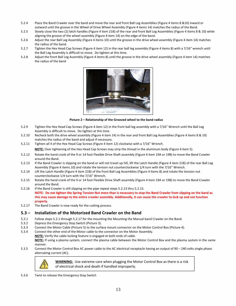
5.2.4 Place the Band Crawler over the band and move the rear and front Ball Leg Assemblies (Figure 4 items 8 &10) inward or outward until the groove in the Wheel of Drive Wheel Assembly (Figure 4 items 14) matches the radius of the Band.
5.2.5 Slowly close the two (2) latch handles (Figure 4 item 21B) of the rear and front Ball Leg Assemblies (Figure 4 items 8 & 10) while aligning the groove of the wheel assembly (Figure 4 item 14) on the edge of the band.
5.2.6 Adjust the rear Ball Leg Assembly (Figure 4 items 10) until the groove in the drive wheel assembly (Figure 4 item 14) matches the radius of the band.
5.2.7 Tighten the Hex Head Cap Screws (Figure 4 item 12) in the rear ball leg assembly (Figure 4 items 8) with a 7/16” wrench until the Ball Leg Assembly is difficult to move. Do tighten at this time.
5.2.8 Adjust the front Ball Leg Assembly (Figure 4 items 8) until the groove in the drive wheel assembly (Figure 4 item 14) matches the radius of the band
5.2.9 Tighten the Hex Head Cap Screws (Figure 4 item 12) in the front ball leg assembly with a 7/16” Wrench until the Ball Leg Assembly is difficult to move. Do tighten at this time.
5.2.10 Recheck both the drive wheel assembly (Figure 4 item 14) in the rear and front Ball Leg Assemblies (Figure 4 items 8 & 10) matches the radius of the band and adjust if necessary.
5.2.11 Tighten all 4 of the Hex Head Cap Screws (Figure 4 item 12) clockwise with a 7/16” Wrench. NOTE: Over tightening of the Hex Head Cap Screws may strip the thread in the aluminum body (Figure 4 item 5).
5.2.12 Rotate the hand crank of the 9 or 14 foot Flexible Drive Shaft assembly (Figure 4 item 19A or 19B) to move the Band Crawler around the Band.
5.2.13 If the Band Crawler is slipping on the band or will not travel up hill, lift the Latch Handle (Figure 4 item 21B) of the rear Ball Leg Assembly (Figure 4 items 10) and rotate the tension nut counterclockwise 1/4 turn with the 7/16” Wrench.
5.2.14 Lift the Latch Handle (Figure 4 item 21B) of the front Ball Leg Assemblies (Figure 4 items 8) and rotate the tension nut counterclockwise 1/4 turn with the 7/16” Wrench.
5.2.15 Rotate the hand crank of the 9 or 14 foot Flexible Drive Shaft assembly (Figure 4 item 19A or 19B) to move the Band Crawler around the Band.
5.2.16 If the Band Crawler is still slipping on the pipe repeat steps 5.2.13 thru 5.2.15. NOTE: Do not tighten the Spring Tension Nut more than is necessary to stop the Band Crawler from slipping on the band as this may cause damage to the entire crawler assembly. Additionally, it can cause the crawler to lock up and not function properly.
5.2.17 The Band Crawler is now ready for the cutting process.
5.3 – Installation of the Motorized Band Crawler on the Band 5.3.1 Follow steps 5.2.1 through 5.2.17 for the mounting the Mounting the Manual band Crawler on the Band. 5.3.2 Depress the Emergency Stop Switch (Picture 3). 5.3.3 Connect the Motor Cable (Picture 5) to the surface mount connector on the Motor Control Box (Picture 4). 5.3.4 Connect the other end of the Motor cable to the connector on the Motor Assembly.
NOTE: Verify the cable locking feature is engaged at both ends of cable. NOTE: If using a plasma system, connect the plasma cable between the Motor Control Box and the plasma system in the same manner.
5.3.5 Connect the Motor Control Box AC power cable to the AC electrical receptacle having an output of 90 – 240 volts single phase alternating current (AC).
5.3.6 Twist to release the Emergency Stop Switch
WARNING: Use extreme care when plugging the Motor Control Box as there is a risk of electrical shock and death if handled improperly.
Picture 2 – Relationship of the Grooved wheel to the band radius

14
5.3.7 The Digital Screen will light up showing the following. 991 – Indicates that a NEMA 23 motor is in use. 992 – Indicates that a NEMA 34 motor is in use. 993 – Indicates that a heavy-duty NEMA 34 motor is in use. 994 & 995 – Check cable connection at Motor Control Box and Motor. 999 – Indicates the Directional Control Switch is in the “Forward” or “Reverse” position. Move to the “Off” position. NOTE: If any other codes appear contact Mathey Dearman prior to continuing the cutting process.
5.3.8 If no faults are present after the motor number appears, the percent of maximum speed will be displayed in the window. 5.3.9 Move the Directional Control Switch to the “Forward” or “Reverse” direction. 5.3.10 Slowly depress the Speed Control Switch until the percent of motor speed reads about 32% so control of the machine can be
maintained should an emergency arise.
5.3.11 Move the Directional Switch in the “Forward” and “Reverse” checking the functionally of the equipment. 5.3.12 Increase and decrease the speed of the machine with the Speed Control Switch checking the functionally of the equipment. 5.3.13 Depress the Emergency Stop Button. 5.3.14 Disconnect the Motor Control Box from the AC power source. 5.3.15 The motorized Band Crawler is now ready for the cutting process
WARNING: There is a risk of electrical shock if the electrical cord between the Motor Control Box and Band Crawler is pinched between the Wheel Assembly and the Band.
Picture 3 – Motor Control Box Face View Picture 4 – Motor Control Box End View
Picture 5 - Cable, Motor Control Box to Motor
Assembly
15
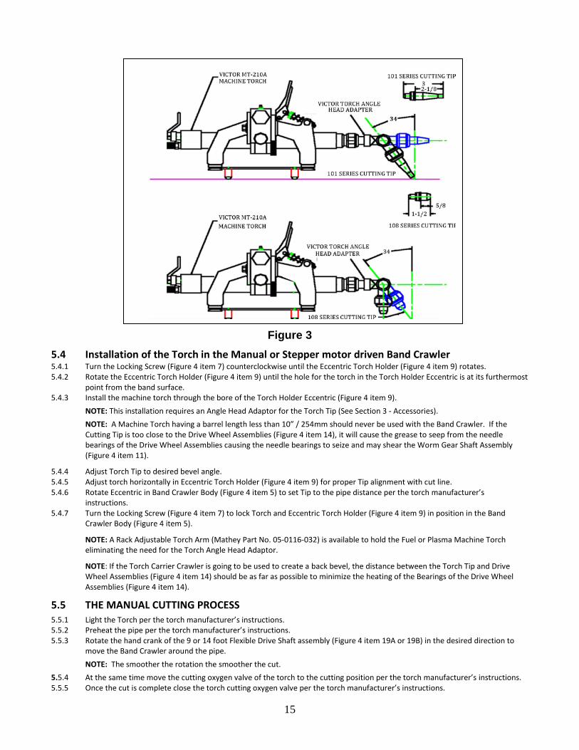
Figure 3 5.4 Installation of the Torch in the Manual or Stepper motor driven Band Crawler 5.4.1 Turn the Locking Screw (Figure 4 item 7) counterclockwise until the Eccentric Torch Holder (Figure 4 item 9) rotates. 5.4.2 Rotate the Eccentric Torch Holder (Figure 4 item 9) until the hole for the torch in the Torch Holder Eccentric is at its furthermost
point from the band surface. 5.4.3 Install the machine torch through the bore of the Torch Holder Eccentric (Figure 4 item 9).
NOTE: This installation requires an Angle Head Adaptor for the Torch Tip (See Section 3 - Accessories). NOTE: A Machine Torch having a barrel length less than 10” / 254mm should never be used with the Band Crawler. If the
Cutting Tip is too close to the Drive Wheel Assemblies (Figure 4 item 14), it will cause the grease to seep from the needle bearings of the Drive Wheel Assemblies causing the needle bearings to seize and may shear the Worm Gear Shaft Assembly (Figure 4 item 11).
5.4.4 Adjust Torch Tip to desired bevel angle. 5.4.5 Adjust torch horizontally in Eccentric Torch Holder (Figure 4 item 9) for proper Tip alignment with cut line. 5.4.6 Rotate Eccentric in Band Crawler Body (Figure 4 item 5) to set Tip to the pipe distance per the torch manufacturer’s
instructions. 5.4.7 Turn the Locking Screw (Figure 4 item 7) to lock Torch and Eccentric Torch Holder (Figure 4 item 9) in position in the Band
Crawler Body (Figure 4 item 5).
NOTE: A Rack Adjustable Torch Arm (Mathey Part No. 05-0116-032) is available to hold the Fuel or Plasma Machine Torch eliminating the need for the Torch Angle Head Adaptor.
NOTE: If the Torch Carrier Crawler is going to be used to create a back bevel, the distance between the Torch Tip and Drive Wheel Assemblies (Figure 4 item 14) should be as far as possible to minimize the heating of the Bearings of the Drive Wheel Assemblies (Figure 4 item 14).
5.5 THE MANUAL CUTTING PROCESS 5.5.1 Light the Torch per the torch manufacturer’s instructions. 5.5.2 Preheat the pipe per the torch manufacturer’s instructions. 5.5.3 Rotate the hand crank of the 9 or 14 foot Flexible Drive Shaft assembly (Figure 4 item 19A or 19B) in the desired direction to
move the Band Crawler around the pipe. NOTE: The smoother the rotation the smoother the cut. 5.5.4 At the same time move the cutting oxygen valve of the torch to the cutting position per the torch manufacturer’s instructions. 5.5.5 Once the cut is complete close the torch cutting oxygen valve per the torch manufacturer’s instructions.

16
5.5.6 Close the Oxygen and fuel gas valves on the torch per the torch manufacturer’s instructions. 5.5.7 Lift the Latch Handles (Figure 4 item 21B) on the Rear and Front Ball Leg Assemblies (Figure 4 items 8 & 10) to release the Band
Crawler from the band. 5.5.8 Lift up on the Band Latch Handle (Figure 2 Item A) 5.5.9 Remove end of the Latch Handle Assembly (Figure 2 Item 5) from the Latch Anchor (Figure 2 Item 3). 5.5.10 Pull the Band Handles (Figure 2 Item 6) outward spreading the ends of the Band apart and remove the Band from the pipe. 5.5.11 Pull the Band Handles (Figure 2 Item 6) together and insert band end with the tangs into the Duckbill (Figure 2 Item 4).
5.5.12 Insert end of the Latch Handle Assembly (Figure 2 Item 5) into the Latch Anchor (Figure 2 Item 3). 5.5.13 Close the Latch Handle Assembly (Figure 2 Item 5) by pushing the Latch Handle (Figure 2 Item A) of the Latch Handle Assembly downward.
5.6 The MOTORIZED CUTTING PROCESS 5.6.1 Depress the Emergency Stop Switch. 5.6.2 Connect the Motor Control Box (Picture 4) to the AC electrical receptacle. 5.6.3 Twist to release the Emergency Stop Switch. 5.6.4 Verify Three (3) Red Zeros (0) appear in the display of Maximum Speed Window. 5.6.5 Slowly depress the speed control switch until the percent of motor speed reads about 32% so control of the machine can be maintained should an emergency arise. 5.6.6 If using an Oxy/Fuel torch, proceed to step 5.6.7. If using a plasma torch, skip to step 5.6.9. 5.6.7 Light the Torch per the torch manufacturer’s instructions. 5.6.8 Preheat the pipe per the torch manufacturer’s instructions. 5.6.9 Move the Directional Control Switch to the “Forward” or “Reverse” position. 5.6.10 Move the cutting oxygen valve of the torch to the cutting position per the torch manufacturer’s instructions.
NOTE: If the motor control box is being used in conjunction with a plasma system, press the plasma button on the front of the motor control box at this time. NOTE: The plasma system connection cable is designed for use with a Hypertherm, Thermal Dynamics, Victor or new ESAB plasma only. Note: Whether using an Oxy/fuel or plasma system, the torch must be moving in order to avoid notching of the pipe, which is not acceptable by most welding codes.
5.6.11 Increase the speed as needed to obtain the best quality cut, while still maintaining control of the machine in case of emergency. 5.6.12 When the cut is complete move the torch cutting oxygen valve to the off position per the torch manufacturer’s instructions. 5.6.12 Close the Oxygen and fuel gas valves on the torch per the torch manufacturer’s instructions.
NOTE: When the cut is complete and the plasma system does not shut off, it will be necessary to depress the plasma button on the front of the motor control box.
5.6.13 Depress the Emergency Stop Switch. 5.6.14 Disconnect the Motor Control Box for the AC electrical receptacle.
5.6.15 Lift the Latch Handles (Figure 4 item 21B) on the Rear and Front Ball Leg Assemblies (Figure 4 items 8 & 10) to release the Band
Crawler from the band. 5.6.16 Lift up on the Band Latch Handle (Figure 2 item A). 5.6.17 Remove end of the Latch Handle Assembly (Figure 2 Item 5) from the Latch Anchor (Figure 2 Item 3). 5.6.18 Pull the Band Handles (Figure 2 Item 6) outward spreading the ends of the Band apart and remove the Band from the pipe. 5.6.19 Pull the Band Handles (Figure 2 Item 6) together and insert band end with the tangs into the Duckbill (Figure 2 Item 4).
WARNING: Keep your finger clear of the area where the band end with the tangs will be inserted into the Duckbill.
WARNING: Use extreme care when plugging the Motor Control Box as there is a risk of electrical shock and death if handled improperly.
WARNING: Use extreme care when plugging the Motor Control Box as there is a risk of electrical shock and death if handled improperly.
WARNING: There is a risk of electrical shock if the electrical cord between the Motor Control Box and Band Crawler is pinched between the Wheel Assembly and the Band.

17
5.6.20 Insert end of the Latch Handle Assembly (Figure 2 Item 5) into the Latch Anchor (Figure 2 Item 3). 5.6.21 Close the Latch Handle Assembly (Figure 2 Item 5) by pushing the Latch Handle (Figure 2 Item A) of the Latch Handle Assembly
downward.
WARNING: Keep your finger clear of the area where the band end with the tangs will be
inserted into the Duckbill.
18
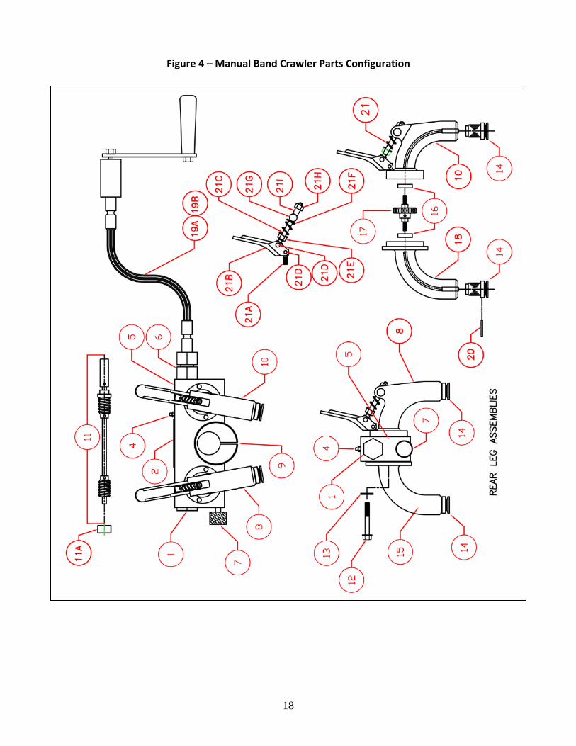
Figure 4 – Manual Band Crawler Parts Configuration

19
Table 4 – Band Crawler Parts Identification
Item Description Part Number Qty.
1 End Plug 05-0116-021 1
2 Name Plate 01-0209-025 1
4 Grease Zerk 01-0469-003 1
5 Crawler Body 05-0116-013 1
6 Connector 05-0116-012 1
7 Locking Screw 05-0116-011 1
8 Front Ball Leg Assembly 05-0116-020 1
9 Eccentric Torch Holder 05-0116-008 1
10 Rear Ball Leg Assembly 05-0116-010 1
11 Worm Shaft Assembly 05-0116-007 1
11A Bearing Housing 05-0116-117 1
12 Hex Head Cap Screw, 1/4-28NF x 2” Lg. 10-14F0-200 4
13 Flat Washer, 1/4” 12-0014-F00 4
14 Drive Wheel Assembly 05-0116-083 4
15 Front Flange Leg Assembly 05-0116-001 1
16 Bearings, Worm Gear Shaft Assembly 05-0116-003 4
17 Worm Gear Assembly Flex Shaft 05-0116-002 2
18 Rear Flange Leg Assembly 05-0116-004 1
19A 9 Foot Flexible Drive Shaft Assembly 05-0116-022 1
19B 14 Foot Flexible Drive Shaft Assembly 05-0116-031 1
20 Spring Pin, 3/32” Ø x 1” lg. 18-3320-100 4
21 Latch Assembly 05-0116-040 2
21A Short Anchor Block 05-0116-061 1
21B Latch Handle 05-0116-016 1
21C Long Anchor Block 05-0116-046 1
21D Rivet, Semi-Tubular 3/16 x 7/8 17-3160-078 2
21E Tension Nut 1H-14F0-000 1
21F Latch Spring 01-0183-013 1
21G Anchor Pin 05-0116-036 1
21H Lock Nut 1L-14FO-000 1
21I Anchor Pin 04-0106-023 1
22 Shim 05-0116-030 1

20
Figure 5 – Motorized Band Crawler Parts Configuration
21
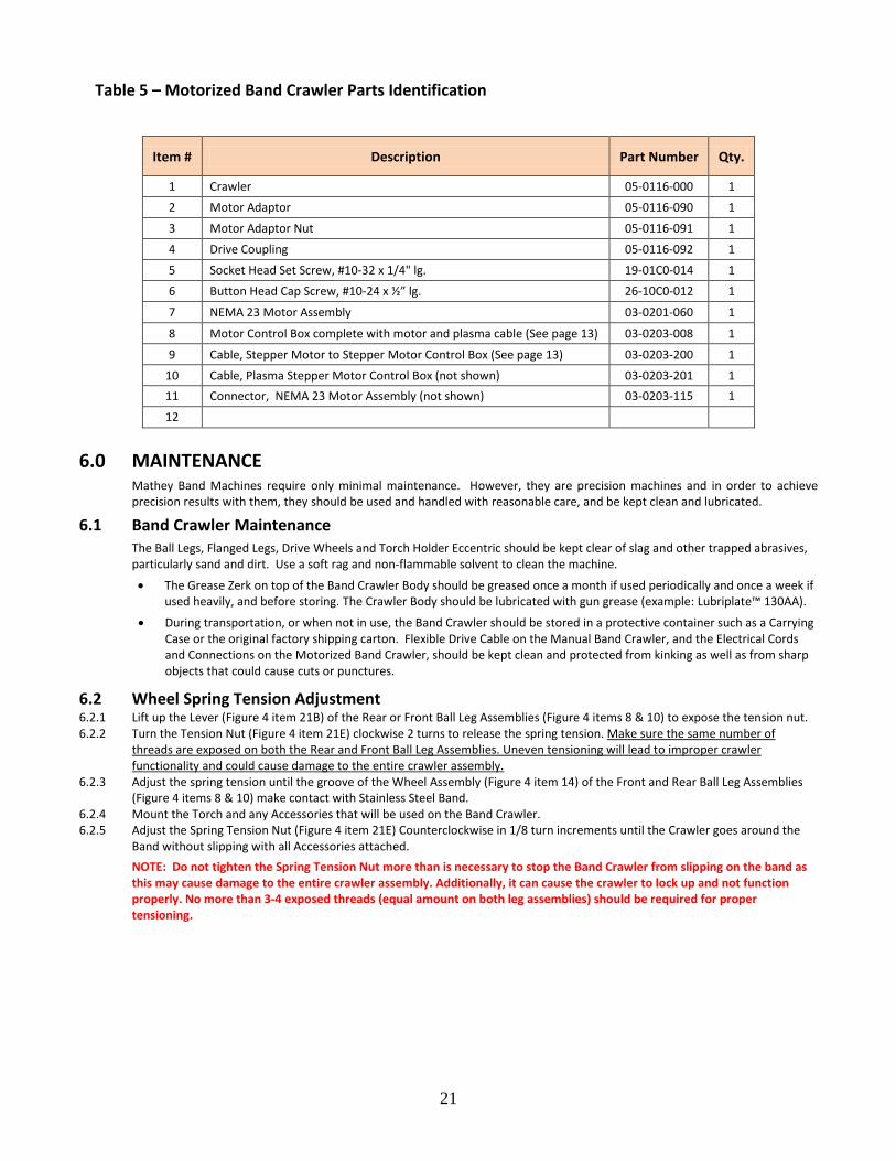
Table 5 – Motorized Band Crawler Parts Identification
6.0 MAINTENANCE Mathey Band Machines require only minimal maintenance. However, they are precision machines and in order to achieve precision results with them, they should be used and handled with reasonable care, and be kept clean and lubricated.
6.1 Band Crawler Maintenance The Ball Legs, Flanged Legs, Drive Wheels and Torch Holder Eccentric should be kept clear of slag and other trapped abrasives, particularly sand and dirt. Use a soft rag and non-flammable solvent to clean the machine.
• The Grease Zerk on top of the Band Crawler Body should be greased once a month if used periodically and once a week if used heavily, and before storing. The Crawler Body should be lubricated with gun grease (example: Lubriplate™ 130AA).
• During transportation, or when not in use, the Band Crawler should be stored in a protective container such as a Carrying Case or the original factory shipping carton. Flexible Drive Cable on the Manual Band Crawler, and the Electrical Cords and Connections on the Motorized Band Crawler, should be kept clean and protected from kinking as well as from sharp objects that could cause cuts or punctures.
6.2 Wheel Spring Tension Adjustment 6.2.1 Lift up the Lever (Figure 4 item 21B) of the Rear or Front Ball Leg Assemblies (Figure 4 items 8 & 10) to expose the tension nut. 6.2.2 Turn the Tension Nut (Figure 4 item 21E) clockwise 2 turns to release the spring tension. Make sure the same number of
threads are exposed on both the Rear and Front Ball Leg Assemblies. Uneven tensioning will lead to improper crawler functionality and could cause damage to the entire crawler assembly.
6.2.3 Adjust the spring tension until the groove of the Wheel Assembly (Figure 4 item 14) of the Front and Rear Ball Leg Assemblies (Figure 4 items 8 & 10) make contact with Stainless Steel Band.
6.2.4 Mount the Torch and any Accessories that will be used on the Band Crawler. 6.2.5 Adjust the Spring Tension Nut (Figure 4 item 21E) Counterclockwise in 1/8 turn increments until the Crawler goes around the
Band without slipping with all Accessories attached. NOTE: Do not tighten the Spring Tension Nut more than is necessary to stop the Band Crawler from slipping on the band as this may cause damage to the entire crawler assembly. Additionally, it can cause the crawler to lock up and not function properly. No more than 3-4 exposed threads (equal amount on both leg assemblies) should be required for proper tensioning.
Item # Description Part Number Qty.
1 Crawler 05-0116-000 1
2 Motor Adaptor 05-0116-090 1
3 Motor Adaptor Nut 05-0116-091 1
4 Drive Coupling 05-0116-092 1
5 Socket Head Set Screw, #10-32 x 1/4" lg. 19-01C0-014 1
6 Button Head Cap Screw, #10-24 x ½” lg. 26-10C0-012 1
7 NEMA 23 Motor Assembly 03-0201-060 1
8 Motor Control Box complete with motor and plasma cable (See page 13) 03-0203-008 1
9 Cable, Stepper Motor to Stepper Motor Control Box (See page 13) 03-0203-200 1
10 Cable, Plasma Stepper Motor Control Box (not shown) 03-0203-201 1 11 Connector, NEMA 23 Motor Assembly (not shown) 03-0203-115 1
12
22
6.3 Installation of the Stepper Motor Kit 6.3.1 Remove Connector (Figure 4 item 6) from the Crawler Body (Figure 4 item 5). 6.3.2 Align the Motor Adaptor (Figure 5 item 2) over the Crawler Body (Figure 4 item 5) so the slot on the Motor Adaptor slides over
the outside of Crawler Body and the hole of the Motor Adaptor aligns with the hole in the Crawler Body where the Connector (Figure 4 item 6) was removed.
6.3.3 Insert the Motor Adaptor Nut (Figure 5 item 3) into Motor Adaptor (Figure 5 item 2) hole and thread it into the Crawler Body (Figure 4 item 5).
6.3.4 Tighten the Motor Adaptor Nut (Figure 5 item 3) with a 7/8” deep socket. 6.3.5 Align the flat in the Motor Coupling (Figure 5 item 4) with the flat on the shaft of the NEMA 23 Motor Assembly (Figure 5 item
7). Slide the Motor Coupling (Figure 5 item 4) onto the shaft of the NEMA 23 Motor Assembly (Figure 5 item 7). 6.3.7 With hex key tighten the #10-32 Socket Set Screw (Figure 5 item 5) in the Motor Coupling (Figure 5 item 4) against the shaft of
the NEMA 23 Motor Assembly (Figure 5 item 7). 6.3.8 Align the female slot of the Motor Coupling (Figure 5 item 4) with the dowel pin of the band crawler motor coupling. Insert the
NEMA 23 Motor Assembly (Figure 5 item 7) into the Motor Adaptor (Figure 5 item 2) until the face of the motor assembly is flush against the face of the motor adaptor.
6.3.9 Align the holes of the NEMA 23 Motor Assembly (Figure 5 item 7) with the threaded holes of the Motor Adaptor (Figure 5 item 2).
6.3.10 Place the #10-24 Button Head Cap Screws (Figure 5 item 6) into the holes of the NEMA 23 Motor Assembly (Figure 5 item 7) and thread them into the Motor Adaptor (Figure 5 item 2). Tighten screws with a 1/8” hex key.
6.3.11 Place a Band on a pipe and install the Crawler on the Band. 6.3.11 Connect the Motor Cable to the NEMA 23 Motor Assembly (Figure 5 item 7) and to the Motor Control Box. 6.3.12 Depress the Emergency Stop Switch. 6.3.13 Move the Directional Control Switch to the “Off” position. 6.3.14 Plug the Motor Control Box into a wall outlet having an output of 90 to 240 volts. 6.3.15 Twist to release the Emergency Stop Switch. 6.3.16 The Digital Screen will light up showing the following.
991 – Indicates that a NEMA 23 motor is in use. 992 – Indicates that a NEMA 34 motor is in use.
993 – Indicates that a heavy-duty NEMA 34 motor is in use. 994 & 995 – Check cable connection at Motor Control Box and Motor. 999 – Indicates the Directional Control Switch is in the “Forward” or “Reverse” position. Move to the “Off” position. NOTE: If any other codes appear contact Mathey Dearman prior to continuing the cutting process.
6.3.17 If no faults are present after the motor number appears, the percent of maximum speed will be displayed in the window. 6.3.18 Move the Directional Control Switch to the “Forward” or “Reverse” direction. 6.3.19 Depress the Speed Control Switch until the percent of motor speed reads about 32% or machine speed or control of the
machine can be maintained should an emergency arise. 6.3.20 If the motorized unit is operating improperly see the trouble shooting in Table 6 on page 23.
6.4 Storage If the Band Crawler will not be used for a period of the time, the machine should be cleaned and regreased with Lubriplate 130-AA. The machine should be stored in a clean and dry place protected from damage.
6.5 Stainless Steel Band Maintenance The Stainless Steel Bands should be kept clean. The Latch Assembly, Latch Handle Assemblies and the slot between the Upper and Lower Duckbills should be kept clear of trapped slag, abrasives, particularly sand and dirt. Bands should be laid on their sides rather than hanging or standing during transportation, or when not in use.
7.0 LIMITATIONS Mathey Dearman is not and will not be responsible for
• Improper use of the Stainless Steel Band or Band Crawler. • Use of the Stainless Steel Band or Band Crawler in violation of any national and/or international electrical and safety
regulations in force. • Connection of the Motorized Band Crawler to an improper or wrong power source. • Faulty maintenance. • Unauthorized modification and/or service of the Stainless Steel Band or Band Crawler. • Use of non-original spare parts or non-specific components. • Lack of observance or partial observance of the operating and maintenance instructions. • Unusual events such as natural disasters, wars, strikes or similar events.
23
8.0 MACHINE SAFETY • The operator and maintenance person shall read and understand the Band Crawler parts and operating manual prior to
attempting operation of the equipment. • The operator and maintenance person shall read and understand the torch parts and operating manual prior to
attempting operation or maintenance of the of the oxy/fuel torch. • Never use the Band Crawler for other than its intended purpose. • Due to the risk of personnel injury never direct the flame or the fuel or plasma torch back toward the machine. • Discontinue the operation of the Band Crawler, if it is vibrating or operating erratically. • When using the Band Crawler, basic safety precautions must always be followed to reduce the risk of personal injury. • Always operate the tool in accordance with the operating instructions. • Always follow the Oxy/fuel or plasma torch manufacturers operating instruction when using the Oxy/fuel or plasma torch
Machine Torch.
9.0 CONDITION OF USE 9.1 Condition of use
• The purpose of the Band Crawler is indicated on section 2.0. Any other use, different from what is listed in section 2.0, could be hazardous to the operator.
• The Band Crawler should be placed in a safe place protected from rain, extreme humidity, mud or accidental impact. • The Band Crawler should never be operated in an extremely humid environment such as fog or rain. • Adopt all the safety devices supplied or suggested by the manufacturer. • No modification to the Saddle Machine or its accessories should be done without the previous written approval by the
manufacturer. • Remember the Motor Control Box is attached to the power source current is applied to the motor control box. The Motor
Control Box should be disconnected from the power source when not in use.
9.2 Use of the Band Crawler not allowed by the Manufacturer • Tampering with the electrical circuit of the Motorized Band Crawler. • Operation of the Band Crawler without the appropriate safety devices. • Perform maintenance with electrical current applied to the Band Crawler. • Use of a liquid or foam fire extinguisher to extinguish a fire in or near the Band Crawler.
10.0 DISPOSAL OF THE BAND AND BAND CRAWLER 10.1 General Information
Do not dispose of any components recklessly without regard for the environment. Separate the components by category for a possible reuse. All national and state regulations should be followed when disposing of waste.
10.2 Composition of the Major Components Component Description Material Crawler Body, Rear Ball Leg, Front Ball Leg, Rear Flange Leg Assembly Aluminum Front Flange Leg Assembly
End Plug, Connector, Worm Shaft Assembly, Drive Wheel Assembly Carbon Steel Bearings, Latch Spring, Latch Anchor, Long Anchor Block
Motor Mounting Bracket Motor Control Box Cover Stainless Steel Electrical Cords Rubber coated copper Cord Retention Holder Plastic
11.0 WARRANTY For warranty details see www.mathey.com
24
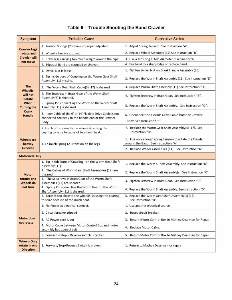
Table 6 – Trouble Shooting the Band Crawler
Symptom Probable Cause Corrective Action
Crawler Legs rotate and
Crawler will not move
1. Tension Springs (23) have improper adjusted. 1. Adjust Spring Tension. See Instruction “A”.
2. Wheel is heavily grooved 2. Replace Wheel Assembly (14) See Instruction “B”.
3. Crawler is carrying too much weight around the pipe. 3. Use a 10” Long 1 3/8” diameter machine torch.
4. Edges of Band are rounded or Uneven. 4. File band to a sharp Edge or replace Band.
The Wheel(s) will not Rotate When
Turning the Crank
Handle
1. Swivel Nut is loose. 1. Tighten Swivel Nut on Crank Handle Assembly (26).
2. Tip inside bore of Coupling on the Worm Gear Shaft Assembly (11) missing. 2. Replace the Worm Shaft Assembly (11). See Instruction “D”.
3. The Worm Gear Shaft Cable(S) (17) is sheared. 3. Replace Worm Shaft Assembly (11) See Instruction “D”.
4. The Setscrew in Brass Gear of the Worm Shaft Assembly(S) is sheared. 4. Tighten Setscrew in Brass Gear. See Instruction “B”.
5. Spring Pin connecting the Worm to the Worm Shaft Assembly (11) is sheared. 5. Replace the Worm Shaft Assembly. See Instruction “D”.
6. Inner Cable of the 9’ or 14’ Flexible Drive Cable is not connected correctly to the handle end or the Crawler Body.
6. Disconnect the Flexible Drive Cable from the Crawler
Body. See Instruction “E”.
7. Torch is too close to the wheel(s) causing the bearing to seize because of too much heat.
7. Replace the Worm Gear Shaft Assembly(s) (17). See Instruction “B”.
Wheels are heavily
Grooved 1. To much Spring (23) tension on the legs
1. Use only enough spring tension to rotate the Crawler around the Band. See Instruction “A”
2. Replace Wheel Assemblies (14). See Instruction “A”
Motorized Only
Motor rotates and Wheels do
not turn
1. Tip in side bore of Coupling on the Worm Gear Shaft Assembly (11). 1. Replace the Worm S haft Assembly. See Instruction “D”.
2. The Cables of Worm Gear Shaft Assemblies (17) are sheared. 2. Replace the Worm Shaft Assembly(s). See Instruction “C”.
3. The Setscrews in Brass Gear of the Worm Shaft Assemblies (17) are sheared. 3. Tighten Setscrew in Brass Gear. See Instruction “C”.
4. Spring Pin connecting the Worm Gear to the Worm Shaft Assembly (11) is sheared. 4. Replace the Worm Shaft Assembly. See Instruction “D”.
5. Torch is too close to the wheel(s) causing the bearing to seize because of too much heat.
5. Replace the Worm Gear Shaft Assembly(s) (17). See Instruction “D”.
Motor does not rotate
1. No Power at electrical connect. 1. Use another electrical source.
2. Circuit breaker tripped 2. Reset circuit breaker.
3. AC Power cord is cut 3. Return Motor Control Box to Mathey Dearman for Repair.
4. Motor Cable between Motor Control Box and motor assembly has open circuit 4. Replace Motor Cable.
5. Forward – Stop – Reverse switch is broken 5. Return Motor Control Box to Mathey Dearman for Repair.
Wheels Only rotate in one
Direction 1. Forward/Stop/Reverse Switch is broken
1. Return to Mathey Dearman for repair.