bandsaw & metal cutting tools - bahco.com · be sharp, use bahco bandsaws welcome to the bahco...
TRANSCRIPT

A registered trademark of SNA Europe Group
BANDSAW & METAL CUTTING TOOLSPrecision tools you can rely on
Precision tools you can rely on:Quality is our number one priority and we also believe that a key factor in both production cutting and general purpose cutting is product consistency. To achieve this, we operate within Bahco’s quality forward system, which uses the ISO 9001-2000 framework. We strive to continually improve our quality management system focusing on customers’ needs and satisfaction.

Be Sharp, Use Bahco Bandsaws
Welcome to the Bahco Metal Cutting Catalogue:In this catalogue we will support you selecting the right bandsaw blade for high production or occasional operational use. Furthermore, this catalogue gives you an overview of our full range of metal cutting tools: holesaws, hacksaws and reciprocating saws, as well as our range of files and rotary burrs.

4
D = y + φ (x º / d2)D = y + φ (x º / d2) D = y + φ (x º / d2)
ø 34 H. 23 (ø 8 +Ω.1977)ø 30 H. 29 (ø 12 + Ω.1981 )
We are manufacturersFACILITIES
Bramley / UK
Minsk / Belarus
Lidköping / Sweden
5
D = y + φ (x º / d2) D = y + φ (x º / d2)D = y + φ (x º / d2)
ø 34 H. 23 (ø 8 +Ω.1977)ø 30 H. 29 (ø 12 +Ω.1981)
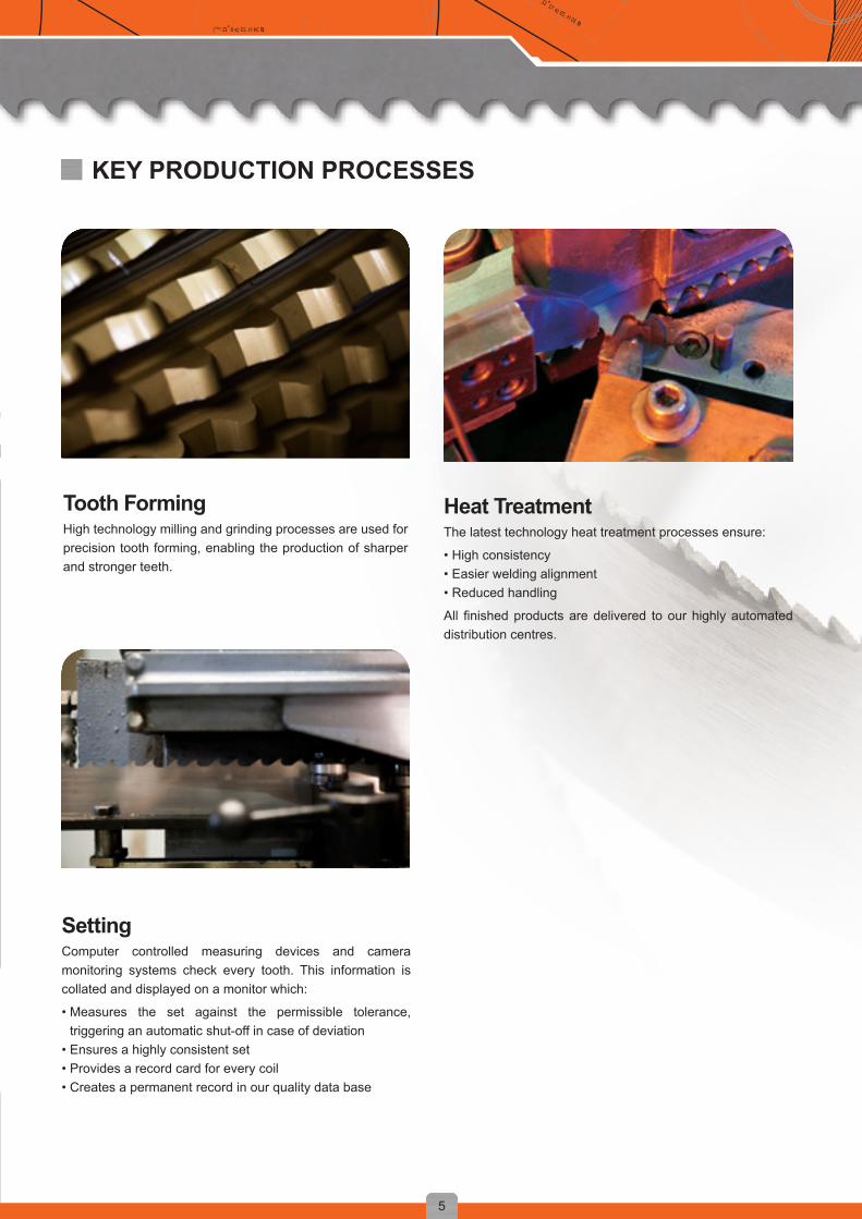
KEY PRODUCTION PROCESSES
Tooth FormingHigh technology milling and grinding processes are used for precision tooth forming, enabling the production of sharper and stronger teeth.
SettingComputer controlled measuring devices and camera monitoring systems check every tooth. This information is collated and displayed on a monitor which:
• Measures the set against the permissible tolerance, triggering an automatic shut-off in case of deviation
• Ensures a highly consistent set• Provides a record card for every coil• Creates a permanent record in our quality data base
Heat TreatmentThe latest technology heat treatment processes ensure:
• High consistency• Easier welding alignment• Reduced handling
All finished products are delivered to our highly automated distribution centres.
6
D = y + φ (x º / d2)D = y + φ (x º / d2) D = y + φ (x º / d2)
ø 34 H. 23 (ø 8 +Ω.1977)ø 30 H. 29 (ø 12 + Ω.1981 )
Serving your Business
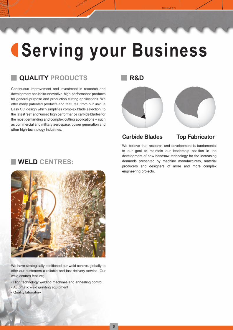
Top FabricatorWe believe that research and development is fundamental to our goal to maintain our leadership position in the development of new bandsaw technology for the increasing demands presented by machine manufacturers, material producers and designers of more and more complex engineering projects.
Carbide Blades
We have strategically positioned our weld centres globally to offer our customers a reliable and fast delivery service. Our weld centres feature;
• High technology welding machines and annealing control • Automatic weld grinding equipment • Quality laboratory
Continuous improvement and investment in research and development has led to innovative, high-performance products for general-purpose and production cutting applications. We offer many patented products and features, from our unique Easy Cut design which simplifies complex blade selection, to the latest ‘set’ and ‘unset’ high performance carbide blades for the most demanding and complex cutting applications – such as commercial and military aerospace, power generation and other high-technology industries.
WELD CENTRES:
QUALITY PRODUCTS R&D

321
7
D = y + φ (x º / d2) D = y + φ (x º / d2)D = y + φ (x º / d2)
ø 34 H. 23 (ø 8 +Ω.1977)ø 30 H. 29 (ø 12 +Ω.1981)
BANDSAW SPECIALIST:TRAINING CENTERS:To expand and maintain our extensive knowledge and experience on band sawing we have our own Bandsaw Academy with training centers across Europe. In our training centre in the UK, Sweden, Italy, Poland, Belarus and Turkey, colleagues, customers and end users are schooled on the product specification, sawing techniques, problem solving and how to achieve the lowest cost per cut.
To provide the best support in our markets and accomplish the lowest cost per cut for our all customers we have our specialists across the globe. These specialists are trained in finding the best possible solution for each application in any specific case. They will help you to reach your target and find the right balance between quality performance and cost efficiency.
BANDCALC on CD and iPad
BANDCALCTM ALLOWS BAHCO BANDSAW USERS TO IDENTIFY THE BEST BAHCO BANDSAW BLADE AND MACHINE PARAMETERS TO OPTIMIZE THEIR BANDSAW CUTTING OPERATION IN JUST 3 STEPS:
SELECT WORK PIECE DIMENSIONS Type, dimensions, surface and type of bundle
SELECT MATERIAL TO CUT
SELECT THE BANDSAW MACHINE Machine condition, band width, thickness and length
BANDCALCTM ALSO ALLOWS BAHCO BANDSAW USERS TO:• Identify the time per cut• Calculate the cost of each cut in their machine• Compare different results between different Bahco blades
THE APPLICATION WILL GIVE YOU THE RECOMMENDED BAHCO BLADE AND PARAMETERS

t
γh
b
w
s
v v
v
v
α
8
D = y + φ (x º / d2)D = y + φ (x º / d2) D = y + φ (x º / d2)
ø 34 H. 23 (ø 8 +Ω.1977)ø 30 H. 29 (ø 12 + Ω.1981 )
TERMINOLOGY
b: width of blades: thickness of bladeh: gullet deptht: tooth pitchα: rakeangleγ: clearanceanglew: width of set
Types of SetThe set is the tilt, or angle, given to the teeth of the saw blade to provide clearance for the blade body and the tooth edges. Below are different types of set:
Raker SetIn the raker set, one tooth is set to the left, one tooth is set to the right, and one tooth (raker) is unset. This set type is used on most evenly pitched blades such as regular and hook. It is also used for contour and friction cutting blades on vertical bandsaw machines.
Combo SetIn the combo set, used on combo toothed blades, a raker (unset) tooth is followed by teeth in a left, right, left, right sequence. This pattern is repeated with each series of teeth starting and ending with the largest tooth in the pattern.

?
9
D = y + φ (x º / d2) D = y + φ (x º / d2)D = y + φ (x º / d2)
ø 34 H. 23 (ø 8 +Ω.1977)ø 30 H. 29 (ø 12 +Ω.1981)
How to select your blade?
4. Order the blade
5. Install the blade 6. Run the blade
1. Analyze application
3. Determine TPI
2. Determine the product
1. Analyze Application
MACHINE
MATERIAL
OTHER NEEDSWhat machine are you using? Brand name, Brand type and machine type. The right blade dimensions depend on the used machine.
Besides the machine specifications it is very important to check the condition in which the machine is. Check at least the condition of the wheels, guides, chip brush and cooland.
Special profiles
Multi layer profiles
Bundle multi-layer
Beams Round bar Bundle of round bars
Bundle of tubes
Tube
Square bar Flat bar

3860-TMC 3881-THQ 3881-THS 3868-TSS 3868-TSX 3869-TS 3860-TCZ 3860-TCT 3860-TCA10-65 100-300 400-800 >1000
200 160-190 110-150 60-90 12% +++ ++ ++ + + ++
140 120-140 85-115 50-70 12% +++ ++ ++ + + ++
120-130 110-120 75-110 40-60 10% +++ ++ ++ + + ++
100-120 90-100 60-90 40-50 10% +++ ++ ++ + + ++
100-110 80-90 60-75 50-60 10% +++ ++ ++ + + ++
80-100 60-90 60-75 45-65 +++ ++ ++ + + ++
85-95 80-90 60-70 50-60 8% +++ ++ ++ + + ++
75-85 70-80 60-70 45-60 8% +++ ++ ++ + + ++
90-105 90-95 60-75 40-55 12% +++ ++ ++ + + ++
80-110 80-100 70-95 65-80 12% +++ ++ +++ +++ + ++
80-90 70-80 60-70 40-50 13% +++ ++ +++ +++ + ++
100-115 80-100 65-80 50-60 12% +++ ++ +++ +++ + ++
30-40 25-30 20-28 15-20 12% +++ ++ + ++
50-60 40-50 35-45 16-18 12% +++ ++ + ++
250 250 250 250 25% ++ ++ ++ + + ++ +++
5000 4000-5000 3000-4000 2000-3000 25% ++ ++ ++ + + +++ ++ +++
250 250 180-240 140-160 4% +++ ++ +++ + + +++
240 220 130-190 100-120 15% +++ ++ +++ + + +++
– – – – – +++
10
D = y + φ (x º / d2)D = y + φ (x º / d2) D = y + φ (x º / d2)
ø 34 H. 23 (ø 8 +Ω.1977)ø 30 H. 29 (ø 12 + Ω.1981 )
Bahco produces a comprehensive range of set and unset carbide bandsaw blades to ensure that we can meet the demands of our production cutting customers.High performance backing steel and optimized carbide grades give premium bandsawing performance. These products will cut faster and last longer than any other bandsaw blade in a wide variety of sawing applications. The blades are designed and produced for high efficiency cutting of difficult and abrasive materials as well as high performance cutting of large and difficult to cut work pieces.
Carbide Blades
2. Determine the Product
1 Structural steel,machining steel
2 Structural steel, quenched and tempered steel
3 Case hardened-, spring steel, quenched and tempered steel
4 Unalloyed tool steel, ball and roller bearing steel
5 High speed steel
6 Cold work tool steel DRY
7 Tool steel, alloyed
8 Nitriding steel, high alloyed hot working steel
9 Cast iron
10 Rust and acid-resistant steel (light)
11 Rust and acid-resistant steel (heavy)
12 Duplex and heat resistant steel
13 Nickel and nickel-cobalt alloys
14 Titanium, titanium alloys; aluminium bronze
15 Horizontal machines, aluminium, aluminium alloys
16 Vertical machines, aluminium, aluminium alloys
17 Brass
18 Copper
19 Special Application
Good + Better ++ Best +++
MaterialMeters per minute at Ø mm
The bigger the size, the lower the speed
COOLANT

3858 PHG P9000
3854-PHG 3854-PQ 3853 Top Fabricator
3857EASY-CUT 3851-PSG 3851 Cobra
10-65 100-300 400-800 >1000
100 85-95 60-75 40-60 6% +++ ++ ++ + + +++ ++
80 70-80 60-68 40-50 6% +++ ++ ++ + + +++ ++
75-100 60-80 45-65 30-40 8% +++ ++ ++ + + +++ ++
60-65 55-60 35-45 25-35 8% +++ ++ +++ + + ++ ++
45-50 40-45 30-35 20-25 8% +++ +++ +++ + + ++ ++
30-35 25-30 20-25 15-20 +++ +++ +++ + + ++ ++
45-65 45-60 40-60 20-40 8% +++ +++ +++ + + ++ ++
40-45 35-40 25-30 20-25 8% +++ +++ +++ + + ++ ++
50-60 45-50 30-40 25-30 +++ +++ +++ + + ++ ++
40-45 40-45 35-40 30-40 10% +++ +++ +++ + + ++ ++
35-40 30-35 20-30 19-22 10% +++ +++ +++ + + ++ ++
25-30 20-25 15-20 14-16 10% +++ +++ +++ + + ++ ++
15-20 13-15 10-12 10 10% +++ +++ +++ + + ++ ++
30-35 25-30 20-25 16-18 10% +++ +++ +++ + + ++ ++
120 120 120 120 25% + ++ + + + +++
3000 2100-2500 1250-2000 500-1200 25% + ++ + + + +++
120 120 90-120 80-100 4% + ++ ++ + + +++ ++
120 110 80-100 60-80 15% + ++ ++ + + +++ ++
– – – – – +++ +++
11
D = y + φ (x º / d2) D = y + φ (x º / d2)D = y + φ (x º / d2)
ø 34 H. 23 (ø 8 +Ω.1977)ø 30 H. 29 (ø 12 +Ω.1981)
High-speed steel tooth tips, combined with flexible alloy-steel backing material results in the most cost effective bandsaw blades for most metal sawing applications.Bi-metal bandsaw blades cover most market requirements, including multi-purpose blades and contour cutting, cutting tubes and profiles, foundry cutting and production cutting.The Sandflex® bandsaw blades cut different types of steel (structural, machining, quenched, tempered, high speed, nitriding) as well as brass, copper, nickel, cast iron, titanium and many other materials.
Bi-metal Blades
1 Structural steel,machining steel
2 Structural steel, quenched and tempered steel
3 Case hardened-, spring steel, quenched and tempered steel
4 Unalloyed tool steel, ball and roller bearing steel
5 High speed steel
6 Cold work tool steel DRY
7 Tool steel, alloyed
8 Nitriding steel, high alloyed hot working steel
9 Cast iron DRY
10 Rust and acid-resistant steel (light)
11 Rust and acid-resistant steel (heavy)
12 Duplex and heat resistant steel
13 Nickel and nickel-cobalt alloys
14 Titanium, titanium alloys; aluminium bronze
15 Horizontal machines, aluminium, aluminium alloys
16 Vertical machines, aluminium, aluminium alloys
17 Brass
18 Copper
19 Special Application
Good + Better ++ Best +++
MaterialMeters per minute at Ø mm
The bigger the size, the lower the speed
COOLANT
?
12
D = y + φ (x º / d2)D = y + φ (x º / d2) D = y + φ (x º / d2)
ø 34 H. 23 (ø 8 +Ω.1977)ø 30 H. 29 (ø 12 + Ω.1981 )
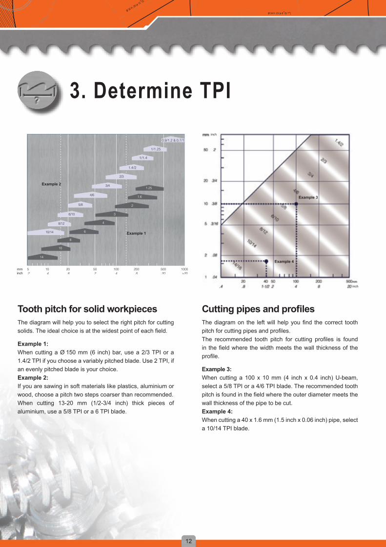
3. Determine TPI
Tooth pitch for solid workpiecesThe diagram will help you to select the right pitch for cutting solids. The ideal choice is at the widest point of each field.
Example 1:When cutting a Ø 150 mm (6 inch) bar, use a 2/3 TPI or a 1.4/2 TPI if you choose a variably pitched blade. Use 2 TPI, if an evenly pitched blade is your choice. Example 2:If you are sawing in soft materials like plastics, aluminium or wood, choose a pitch two steps coarser than recommended.When cutting 13-20 mm (1/2-3/4 inch) thick pieces of aluminium, use a 5/8 TPI or a 6 TPI blade.
CuttingpipesandprofilesThe diagram on the left will help you find the correct tooth pitch for cutting pipes and profiles.The recommended tooth pitch for cutting profiles is found in the field where the width meets the wall thickness of the profile.
Example 3: When cutting a 100 x 10 mm (4 inch x 0.4 inch) U-beam, select a 5/8 TPI or a 4/6 TPI blade. The recommended tooth pitch is found in the field where the outer diameter meets the wall thickness of the pipe to be cut.Example 4: When cutting a 40 x 1.6 mm (1.5 inch x 0.06 inch) pipe, select a 10/14 TPI blade.
inch
inch
inch
Example 1
Example 2
Example 3
Example 4

1 2 3 5 10 20 30 40 50 75 100 150 200
13
D = y + φ (x º / d2) D = y + φ (x º / d2)D = y + φ (x º / d2)
ø 34 H. 23 (ø 8 +Ω.1977)ø 30 H. 29 (ø 12 +Ω.1981)
EASY-CUTChoose S (Small), M (Medium) or L (Large), depending on the cutting range you need.
Table of RadiusBand Width:The band width is measured from the tip of the teeth to the back edge of the blade.On horizontal machines, the band width is dependent upon the bandsaw machine being used. There is, however, some variation possible on vertical machines.For contour sawing, the blade should be as wide as the machine permits, but still narrow enough so that it can cut the desired shape. Please see diagram below.
EASY-CUT - Cutting DATA
Material Size (mm)Order Code Blade SizeWidth x Thickness
Within any size range Small = Good surface finish Medium = Good band life Large = Speed of cut
Min
imum
radi
us
mminch
1 2 3 4
1”4 TPI
1. 2. 3.
14
D = y + φ (x º / d2)D = y + φ (x º / d2) D = y + φ (x º / d2)
ø 34 H. 23 (ø 8 +Ω.1977)ø 30 H. 29 (ø 12 + Ω.1981 )
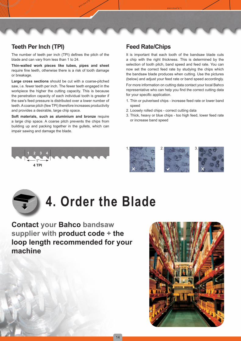
Teeth Per Inch (TPI)The number of teeth per inch (TPI) defines the pitch of the blade and can vary from less than 1 to 24.Thin-walled work pieces like tubes, pipes and sheet require fine teeth, otherwise there is a risk of tooth damage or breakage.Large cross sections should be cut with a coarse-pitched saw, i.e. fewer teeth per inch. The fewer teeth engaged in the workpiece the higher the cutting capacity. This is because the penetration capacity of each individual tooth is greater if the saw's feed pressure is distributed over a lower number of teeth. A coarse pitch (few TPI) therefore increases productivity and provides a desirable, large chip space.Soft materials, such as aluminium and bronze require a large chip space. A coarse pitch prevents the chips from building up and packing together in the gullets, which can impair sawing and damage the blade.
Feed Rate/ChipsIt is important that each tooth of the bandsaw blade cuts a chip with the right thickness. This is determined by the selection of tooth pitch, band speed and feed rate. You can now set the correct feed rate by studying the chips which the bandsaw blade produces when cutting. Use the pictures (below) and adjust your feed rate or band speed accordingly.For more information on cutting data contact your local Bahco representative who can help you find the correct cutting data for your specific application.1. Thin or pulverised chips - increase feed rate or lower band
speed2. Loosely rolled chips - correct cutting data3. Thick, heavy or blue chips - too high feed, lower feed rate
or increase band speed
4. Order the BladeContact your Bahco bandsaw supplier with product code + the loop length recommended for your machine

15
D = y + φ (x º / d2) D = y + φ (x º / d2)D = y + φ (x º / d2)
ø 34 H. 23 (ø 8 +Ω.1977)ø 30 H. 29 (ø 12 +Ω.1981)
5. Mount the blade
MachineCheck frequently:
• The operation of the chip brush• The wear and alignment of the guides• The band tension with a tensionmeter (see page 35)• The band speed with a tachometer (see page 35)• The coolant concentration with a refractometer (see page 35)
Coolant / Cutting fluidThe coolant lubricates, cools and carries the chips from thecut. It is important to:• Use appropiate cutting fluid• Use recommended concentration of cutting fluid• Make sure that the cutting fluid reaches the cut with low
pressure and large flow
Workpiece• Make sure that the workpiece is firmly clamped so that it
cannot vibrate or rotate• Do not use bent or damaged workpieces
Tooth protectorKeep the tooth protector on the blade until it is mounted onthe machine to avoid premature chipping of the tooth tips.
6. Run the bladeFor Bi-metal blades: to obtain the maximum blade life always use the recommended band speed but lower the feed rate to 1/3-1/2 during the first10minutes of cutting.
During the next 10 minutes increase the feed rate in stages, until you have reached the recommended feed rate.
For Carbide blades another running in procedure is needed. Contact our bandsaw specialist for assistance with this procedure.
1 2 3 4 56 7 8 9 1011 12 13 14 1516 17 18 19
3860
16
D = y + φ (x º / d2)D = y + φ (x º / d2) D = y + φ (x º / d2)
ø 34 H. 23 (ø 8 +Ω.1977)ø 30 H. 29 (ø 12 + Ω.1981 )
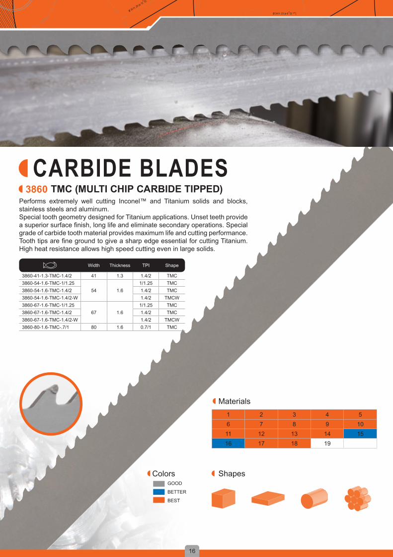
CARBIDE BLADESPerforms extremely well cutting Inconel™ and Titanium solids and blocks, stainless steels and aluminum.Special tooth geometry designed for Titanium applications. Unset teeth provide a superior surface finish, long life and eliminate secondary operations. Special grade of carbide tooth material provides maximum life and cutting performance. Tooth tips are fine ground to give a sharp edge essential for cutting Titanium. High heat resistance allows high speed cutting even in large solids.
ColorsGOOD
BETTER
BEST
TMC (MULTI CHIP CARBIDE TIPPED)
Width Thickness TPI Shape
3860-41-1.3-TMC-1.4/2 41 1.3 1.4/2 TMC3860-54-1.6-TMC-1/1.25
54 1.61/1.25 TMC
3860-54-1.6-TMC-1.4/2 1.4/2 TMC3860-54-1.6-TMC-1.4/2-W 1.4/2 TMCW3860-67-1.6-TMC-1/1.25
67 1.61/1.25 TMC
3860-67-1.6-TMC-1.4/2 1.4/2 TMC3860-67-1.6-TMC-1.4/2-W 1.4/2 TMCW3860-80-1.6-TMC-.7/1 80 1.6 0.7/1 TMC
Materials
Shapes
1 2 3 4 56 7 8 9 1011 12 13 14 1516 17 18 19
3881
17
D = y + φ (x º / d2) D = y + φ (x º / d2)D = y + φ (x º / d2)
ø 34 H. 23 (ø 8 +Ω.1977)ø 30 H. 29 (ø 12 +Ω.1981)
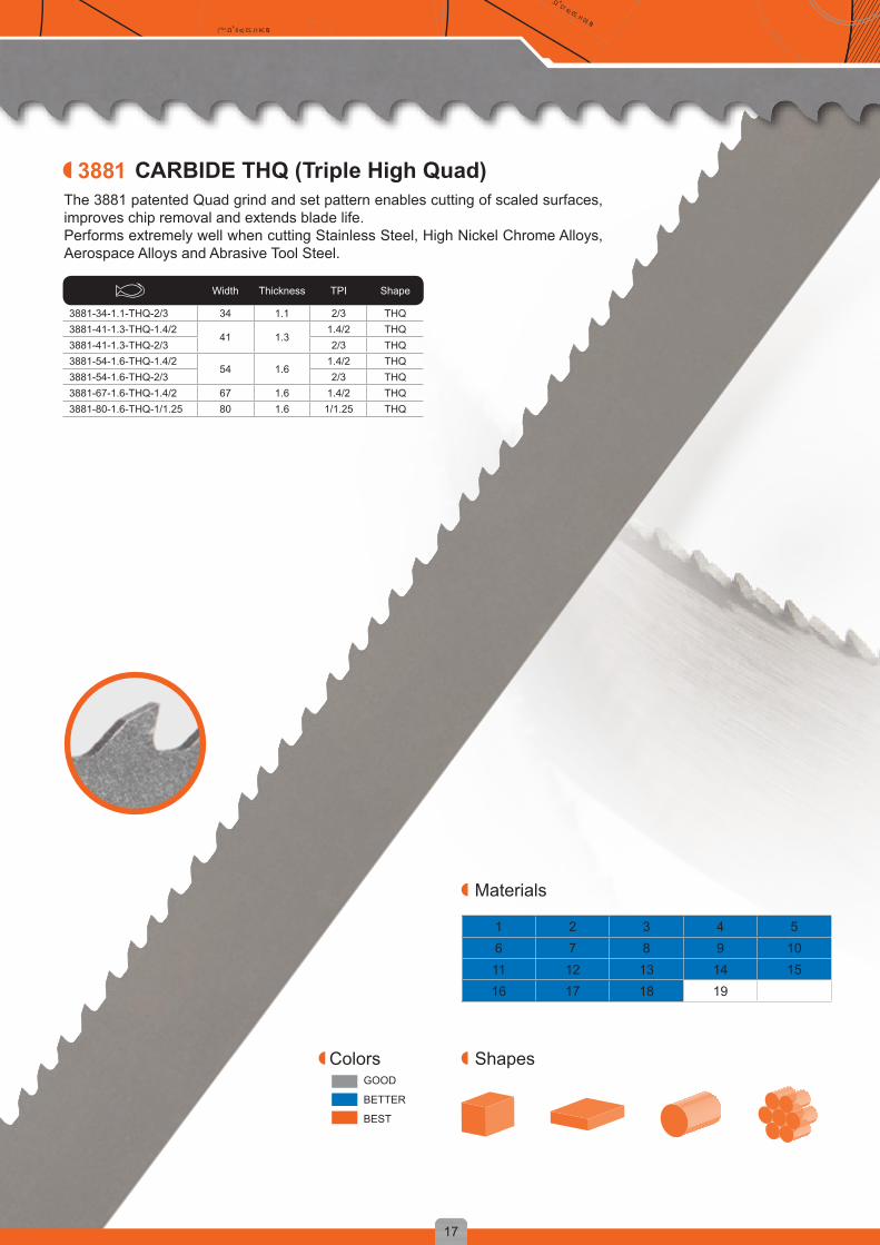
The 3881 patented Quad grind and set pattern enables cutting of scaled surfaces, improves chip removal and extends blade life.Performs extremely well when cutting Stainless Steel, High Nickel Chrome Alloys, Aerospace Alloys and Abrasive Tool Steel.
ColorsGOOD
BETTER
BEST
CARBIDE THQ (Triple High Quad)
Width Thickness TPI Shape
3881-34-1.1-THQ-2/3 34 1.1 2/3 THQ3881-41-1.3-THQ-1.4/2
41 1.31.4/2 THQ
3881-41-1.3-THQ-2/3 2/3 THQ3881-54-1.6-THQ-1.4/2
54 1.61.4/2 THQ
3881-54-1.6-THQ-2/3 2/3 THQ3881-67-1.6-THQ-1.4/2 67 1.6 1.4/2 THQ3881-80-1.6-THQ-1/1.25 80 1.6 1/1.25 THQ
Materials
Shapes

1 2 3 4 56 7 8 9 1011 12 13 14 1516 17 18 19
3881
18
D = y + φ (x º / d2)D = y + φ (x º / d2) D = y + φ (x º / d2)
ø 34 H. 23 (ø 8 +Ω.1977)ø 30 H. 29 (ø 12 + Ω.1981 )
The 3881 patented Quad grind and set pattern enables cutting of scaled surfaces, improves chip removal and extends blade life.Performs extremely well cutting Stainless Steel, High Nickel Chrome Alloys, Aerospace Alloys and Abrasive Tool Steel.
- Patented edge preparation - Eliminates breaking in - Reduce tooth strippage on breagthrough - Same design as THQ, but wirh an extremely low noise level - Not suitbable for Titanium applications
Materials
ShapesColorsGOOD
BETTER
BEST
CARBIDE THS (TRIPLE HIGH QUAD - HONED)
Width Thickness TPI Shape
3881-41-1.3-THS-1.4/2 41 1.3 1.4/2 THS3881-54-1.6-THS-1/1.25
54 1.61/1.25 THS
3881-54-1.6-THS-1.4/2 1.4/2 THS3881-67-1.6-THS-1/1.25
67 1.61/1.25 THS
3881-67-1.6-THS-1.4/2 1.4/2 THS3881-80-1.6-THS-.7/1 80 1.6 0.7/1 THS

1 2 3 4 56 7 8 9 1011 12 13 14 1516 17 18 19
3868
19
D = y + φ (x º / d2) D = y + φ (x º / d2)D = y + φ (x º / d2)
ø 34 H. 23 (ø 8 +Ω.1977)ø 30 H. 29 (ø 12 +Ω.1981)
Patented edge preparation reduces vibration and provides an extremely low noise level. Designed specifically for production cutting of stainless steel. The teeth of are tipped with a special grade of carbide to cut the most difficult materials. Provides clearance for good chip removal. Perfect for cutting, high nickel alloys, stainless steel, abrasive tool steel, abrasive aerospace alloys.
Materials
ShapesColorsGOOD
BETTER
BEST
CARBIDE TSS (TRIPLE SET STAINLESS - HONED)
Width Thickness TPI Shape
3868-41-1.3-TSS-1.4/241 1.3
1.4/2 TSS3868-41-1.3-TSS-2/3 2/3 TSS3868-54-1.6-TSS-1/1.25
54 1.61/1.25 TSS
3868-54-1.6-TSS-1.4/2 1.4/2 TSS3868-67-1.6-TSS-1/1.25 67 1.6 1/1.25 TSS
1 2 3 4 56 7 8 9 1011 12 13 14 1516 17 18 19
3868
20
D = y + φ (x º / d2)D = y + φ (x º / d2) D = y + φ (x º / d2)
ø 34 H. 23 (ø 8 +Ω.1977)ø 30 H. 29 (ø 12 + Ω.1981 )
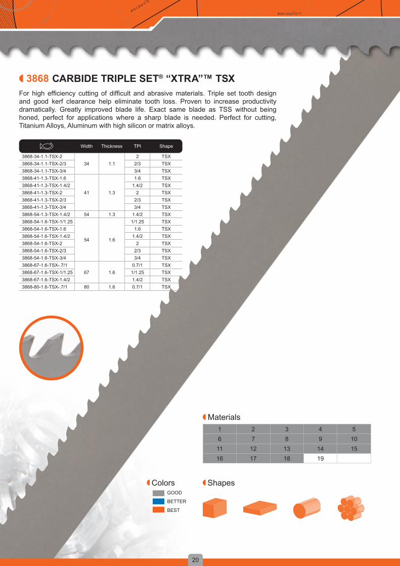
For high efficiency cutting of difficult and abrasive materials. Triple set tooth design and good kerf clearance help eliminate tooth loss. Proven to increase productivity dramatically. Greatly improved blade life. Exact same blade as TSS without being honed, perfect for applications where a sharp blade is needed. Perfect for cutting, Titanium Alloys, Aluminum with high silicon or matrix alloys.
Materials
ShapesColorsGOOD
BETTER
BEST
CARBIDE TRIPLE SET® “XTRA”™ TSX
Width Thickness TPI Shape
3868-34-1.1-TSX-234 1.1
2 TSX3868-34-1.1-TSX-2/3 2/3 TSX3868-34-1.1-TSX-3/4 3/4 TSX3868-41-1.3-TSX-1.6
41 1.3
1.6 TSX3868-41-1.3-TSX-1.4/2 1.4/2 TSX3868-41-1.3-TSX-2 2 TSX3868-41-1.3-TSX-2/3 2/3 TSX3868-41-1.3-TSX-3/4 3/4 TSX3868-54-1.3-TSX-1.4/2 54 1.3 1.4/2 TSX3868-54-1.6-TSX-1/1.25
54 1.6
1/1.25 TSX3868-54-1.6-TSX-1.6 1.6 TSX3868-54-1.6-TSX-1.4/2 1.4/2 TSX3868-54-1.6-TSX-2 2 TSX3868-54-1.6-TSX-2/3 2/3 TSX3868-54-1.6-TSX-3/4 3/4 TSX3868-67-1.6-TSX-.7/1
67 1.60.7/1 TSX
3868-67-1.6-TSX-1/1.25 1/1.25 TSX3868-67-1.6-TSX-1.4/2 1.4/2 TSX3868-80-1.6-TSX-.7/1 80 1.6 0.7/1 TSX

1 2 3 4 56 7 8 9 1011 12 13 14 1516 17 18 19
3860
21
D = y + φ (x º / d2) D = y + φ (x º / d2)D = y + φ (x º / d2)
ø 34 H. 23 (ø 8 +Ω.1977)ø 30 H. 29 (ø 12 +Ω.1981)
For high efficiency cutting of difficult and abrasive materials. The Multi-Chip Unset Carbide Tipped bandsaw. Special tooth geometry designed for hard chrome bars. Unset teeth provide a superior finish, long life and eliminate secondary operations.
Materials
ShapesColorsGOOD
BETTER
BEST
TCZ
Width Thickness TPI Shape
3860-34-1.1-TCZ-2/3 34 1.1 2/3 TCZ3860-34-1.1-TCZ-3/4 34 1.1 3/4 TCZ3860-41-1.3-TCZ-2/3 41 1.3 2/3 TCZ3860-41-1.3-TCZ-3/4 41 1.3 3/4 TCZ

1 2 3 4 56 7 8 9 1011 12 13 14 1516 17 18 19
3869
22
D = y + φ (x º / d2)D = y + φ (x º / d2) D = y + φ (x º / d2)
ø 34 H. 23 (ø 8 +Ω.1977)ø 30 H. 29 (ø 12 + Ω.1981 )
For cutting non-ferrous and abrasive materials.Perfect for aluminium gates and risers, magnesium, zirconium, plastics and other abrasive materials.Special design for foundry use incorporating fast cutting and easy feeding.
Materials
ShapesColorsGOOD
BETTER
BEST
CARBIDE TRIPLE SET
Width Thickness TPI Shape
3869-13-0.9-TS-3 13 0.9 3 TS3869-20-0.9-TS-3
20 0.93 TS
3869-20-0.9-TS-4 4 TS3869-27-0.9-TS-3
27 0.93 TS
3869-27-0.9-TS-4 4 TS3869-29-1.1-TS-2 29 1.1 2 TS3869-34-1.1-TS-3 34 1.1 3 TS
1 2 3 4 56 7 8 9 1011 12 13 14 1516 17 18 19
3860
23
D = y + φ (x º / d2) D = y + φ (x º / d2)D = y + φ (x º / d2)
ø 34 H. 23 (ø 8 +Ω.1977)ø 30 H. 29 (ø 12 +Ω.1981)
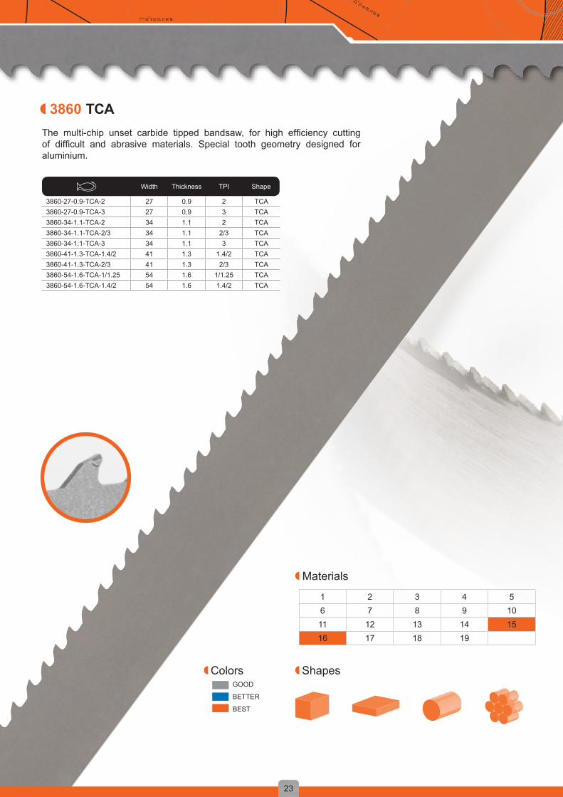
The multi-chip unset carbide tipped bandsaw, for high efficiency cutting of difficult and abrasive materials. Special tooth geometry designed for aluminium.
Materials
ShapesColorsGOOD
BETTER
BEST
TCA
Width Thickness TPI Shape
3860-27-0.9-TCA-2 27 0.9 2 TCA3860-27-0.9-TCA-3 27 0.9 3 TCA3860-34-1.1-TCA-2 34 1.1 2 TCA3860-34-1.1-TCA-2/3 34 1.1 2/3 TCA3860-34-1.1-TCA-3 34 1.1 3 TCA3860-41-1.3-TCA-1.4/2 41 1.3 1.4/2 TCA3860-41-1.3-TCA-2/3 41 1.3 2/3 TCA3860-54-1.6-TCA-1/1.25 54 1.6 1/1.25 TCA3860-54-1.6-TCA-1.4/2 54 1.6 1.4/2 TCA
1 2 3 4 56 7 8 9 1011 12 13 14 1516 17 18 19
3860
24
D = y + φ (x º / d2)D = y + φ (x º / d2) D = y + φ (x º / d2)
ø 34 H. 23 (ø 8 +Ω.1977)ø 30 H. 29 (ø 12 + Ω.1981 )
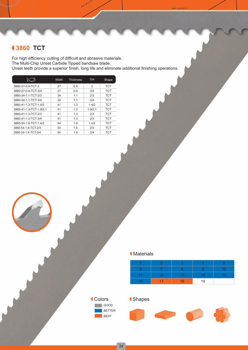
For high efficiency cutting of difficult and abrasive materials.The Multi-Chip Unset Carbide Tipped bandsaw blade.Unset teeth provide a superior finish, long life and eliminate additional finishing operations.
Materials
ShapesColorsGOOD
BETTER
BEST
Width Thickness TPI Shape
3860-27-0.9-TCT-3 27 0.9 3 TCT3860-27-0.9-TCT-3/4 27 0.9 3/4 TCT3860-34-1.1-TCT-2/3 34 1.1 2/3 TCT3860-34-1.1-TCT-3/4 34 1.1 3/4 TCT3860-41-1.3-TCT-1.4/2 41 1.3 1.4/2 TCT3860-41-1.3-TCT-1.9/2.1 41 1.3 1.9/2.1 TCT3860-41-1.3-TCT-2/3 41 1.3 2/3 TCT3860-41-1.3-TCT-3/4 41 1.3 2/3 TCT3860-54-1.6-TCT-1.4/2 54 1.6 1.4/2 TCT3860-54-1.6-TCT-2/3 54 1.6 2/3 TCT3860-54-1.6-TCT-3/4 54 1.6 3/4 TCT
TCT

25
D = y + φ (x º / d2) D = y + φ (x º / d2)D = y + φ (x º / d2)
ø 34 H. 23 (ø 8 +Ω.1977)ø 30 H. 29 (ø 12 +Ω.1981)

1 2 3 4 56 7 8 9 1011 12 13 14 1516 17 18 19
3858
26
D = y + φ (x º / d2)D = y + φ (x º / d2) D = y + φ (x º / d2)
ø 34 H. 23 (ø 8 +Ω.1977)ø 30 H. 29 (ø 12 + Ω.1981 )
For production cutting on various types of materials, especially alloyed and stainless steels.Specifically designed to cut all difficult materials, in medium and large work pieces with a high performance. The use of powder hss will improve the hardness of the blade, as well the toughness of the 3858–sandflex PHG P9000. This truly leads to an excellent performance of the tooth edges. The combo phg is a patented ground tooth shape with positive rake angle for good penetration of large sections of Tough-to-cut alloys and work hardening materials.
Materials
ShapesColorsGOOD
BETTER
BEST
SANDFLEX® PHG P9000
Width Thickness TPI Shape
3858-41-1.3-PHG-1.4/2 41 1.3
1.4/2 PHG3858-41-1.3-PHG-2/3 2/3 PHG3858-41-1.3-PHG-3/4 3/4 PHG3858-54-1.6-PHG-.7/1
54 1.6.7/1 PHG
3858-54-1.6-PHG-1.4/2 1.4/2 PHG3858-54-1.6-PHG-2/3 2/3 PHG
BI-METAL BLADES
1 2 3 4 56 7 8 9 1011 12 13 14 1516 17 18 19
3854
27
D = y + φ (x º / d2) D = y + φ (x º / d2)D = y + φ (x º / d2)
ø 34 H. 23 (ø 8 +Ω.1977)ø 30 H. 29 (ø 12 +Ω.1981)
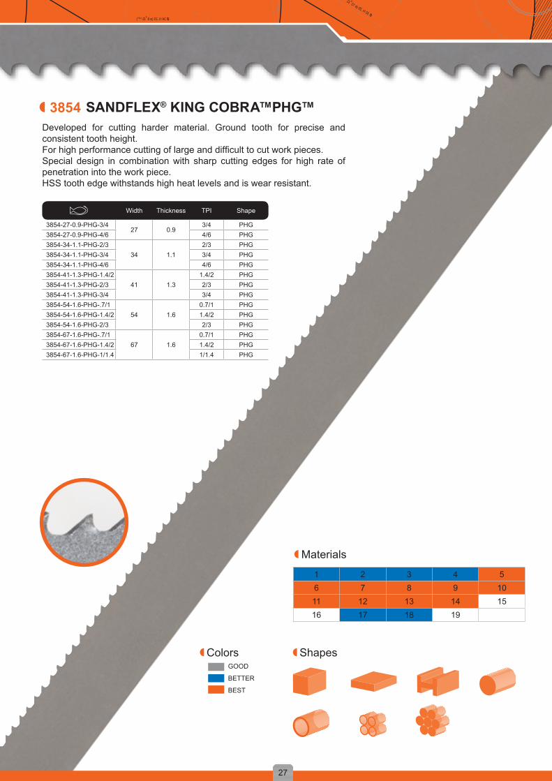
Developed for cutting harder material. Ground tooth for precise and consistent tooth height.For high performance cutting of large and difficult to cut work pieces.Special design in combination with sharp cutting edges for high rate of penetration into the work piece.HSS tooth edge withstands high heat levels and is wear resistant.
Materials
ShapesColorsGOOD
BETTER
BEST
SANDFLEX® KING COBRA™PHG™
Width Thickness TPI Shape
3854-27-0.9-PHG-3/427 0.9
3/4 PHG3854-27-0.9-PHG-4/6 4/6 PHG3854-34-1.1-PHG-2/3
34 1.12/3 PHG
3854-34-1.1-PHG-3/4 3/4 PHG3854-34-1.1-PHG-4/6 4/6 PHG3854-41-1.3-PHG-1.4/2
41 1.31.4/2 PHG
3854-41-1.3-PHG-2/3 2/3 PHG3854-41-1.3-PHG-3/4 3/4 PHG3854-54-1.6-PHG-.7/1
54 1.60.7/1 PHG
3854-54-1.6-PHG-1.4/2 1.4/2 PHG3854-54-1.6-PHG-2/3 2/3 PHG3854-67-1.6-PHG-.7/1
67 1.60.7/1 PHG
3854-67-1.6-PHG-1.4/2 1.4/2 PHG3854-67-1.6-PHG-1/1.4 1/1.4 PHG

1 2 3 4 56 7 8 9 1011 12 13 14 1516 17 18 19
3854
28
D = y + φ (x º / d2)D = y + φ (x º / d2) D = y + φ (x º / d2)
ø 34 H. 23 (ø 8 +Ω.1977)ø 30 H. 29 (ø 12 + Ω.1981 )
Very positive rake angle allows good penetration into difficult to cut materials.The wedge angle of 48° gives a strong tooth.The tooth design improves cutting performance in special alloys with work hardening properties.The different set levels produce a multi chip cutting profile which reduces cutting forces and improves blade life.
Materials
ShapesColorsGOOD
BETTER
BEST
Width Thickness TPI Shape
3854-27-0.9-PQ-3/4 27 0.9 3/4 PQ3854-34-1.1-PQ-2/3
34 1.12/3 PQ
3854-34-1.1-PQ-3/4 3/4 PQ3854-41-1.3-PQ-1.4/2
41 1.31.4/2 PQ
3854-41-1.3-PQ-2/3 2/3 PQ3854-41-1.3-PQ-3/4 3/4 PQ3854-54-1.6-PQ-.9/1.2
54 1.6
0.9/1.2 PQ3854-54-1.6-PQ-1.4/2 1.4/2 PQ3854-54-1.6-PQ-2/3 2/3 PQ3854-54-1.6-PQ-3/4 3/4 PQ3854-67-1.6-PQ-.9/1.2
67 1.60.9/1.2 PQ
3854-67-1.6-PQ-1.4/2 1.4/2 PQ3854-67-1.6-PQ-2/3 2/3 PQ
SANDFLEX® KING COBRA™ PQ

1 2 3 4 56 7 8 9 1011 12 13 14 1516 17 18 19
3853
29
D = y + φ (x º / d2) D = y + φ (x º / d2)D = y + φ (x º / d2)
ø 34 H. 23 (ø 8 +Ω.1977)ø 30 H. 29 (ø 12 +Ω.1981)
For cutting of structural steels, tubes and profiles in bundles or single pieces.Precise tooth set for smooth surface finish.
Materials
ShapesColorsGOOD
BETTER
BEST
Width Thickness TPI Shape
3853-27-0.9-3/427 0.9
3/4 PF3853-27-0.9-4/6 4/6 PF3853-27-0.9-5/8 5/8 PF3853-34-1.1-2/3
34 1.1
2/3 PF3853-34-1.1-3/4 3/4 PF3853-34-1.1-4/6 4/6 PF3853-34-1.1-5/8 5/8 PF3853-41-1.3-2/3
41 1.3
2/3 PF3853-41-1.3-3/4 3/4 PF3853-41-1.3-4/6 4/6 PF3853-41-1.3-5/8 5/8 PF3853-54-1.6-2/3
54 1.62/3 PF
3853-54-1.6-3/4 3/4 PF3853-54-1.6-4/6 4/6 PF3853-67-1.6-2/3
67 1.62/3 PF
3853-67-1.6-3/4 3/4 PF
SANDFLEX® TOP FABRICATOR

1 2 3 4 56 7 8 9 1011 12 13 14 1516 17 18 19
3857
30
D = y + φ (x º / d2)D = y + φ (x º / d2) D = y + φ (x º / d2)
ø 34 H. 23 (ø 8 +Ω.1977)ø 30 H. 29 (ø 12 + Ω.1981 )
The generation of bandsaw blades to meet the requirements of the multi-purpose customer. Patented tooth form suitable to cut a variety of sizes and materials with just one blade. In this application this blade achieves double blade life compared with standard blades.
Easy-Cut blades cut almost anything without changing blades!
• Tool Steel • Wood • Pipe• Mild Steel • Plastic • Channel• Stainless Steel • Sheet Metal • Angle Iron• Aluminum • Tubing • I Beams• Copper • Solids • H Beams• Brass • Bundles • Drill Rods
Materials
ShapesColorsGOOD
BETTER
BEST
Width Thickness Size
3857-13-0.6-EZ-L13 0.6
Large3857-13-0.6-EZ-M Medium3857-13-0.6-EZ-S Small3857-20-0.9-EZ-L
20 0.9Large
3857-20-0.9-EZ-M Medium3857-20-0.9-EZ-S Small3857-27-0.9-EZ-L
27 0.9Large
3857-27-0.9-EZ-M Medium3857-27-0.9-EZ-S Small3857-34-1.1-EZ-L
34 1.1Large
3857-34-1.1-EZ-M Medium3857-34-1.1-EZ-S Small
MULTI-PURPOSE EASY-CUT

1 2 3 4 56 7 8 9 1011 12 13 14 1516 17 18 19
3851
31
D = y + φ (x º / d2) D = y + φ (x º / d2)D = y + φ (x º / d2)
ø 34 H. 23 (ø 8 +Ω.1977)ø 30 H. 29 (ø 12 +Ω.1981)
For production cutting on various types of materials, especially alloyed and stainless steels.Ground tooth for precise and consistent tooth height.Precise tooth set for smooth surface finish.
Materials
ShapesColorsGOOD
BETTER
BEST
Width Thickness TPI Shape
3851-27-0.9-PSG-2/327 0.9
2/3 PSG3851-27-0.9-PSG-3/4 3/4 PSG3851-27-0.9-PSG-4/6 4/6 PSG3851-34-1.1-PSG-2/3
34 1.12/3 PSG
3851-34-1.1-PSG-3/4 3/4 PSG3851-34-1.1-PSG-4/6 4/6 PSG3851-41-1.3-PSG-1.4/2
41 1.3
1.4/2 PSG3851-41-1.3-PSG-2/3 2/3 PSG3851-41-1.3-PSG-3/4 3/4 PSG3851-41-1.3-PSG-4/6 4/6 PSG3851-54-1.6-PSG-1.4/2
54 1.61.4/2 PSG
3851-54-1.6-PSG-2/3 2/3 PSG3851-54-1.6-PSG-3/4 3/4 PSG
SANDFLEX® COBRA™ PSG

3851
32
D = y + φ (x º / d2)D = y + φ (x º / d2) D = y + φ (x º / d2)
ø 34 H. 23 (ø 8 +Ω.1977)ø 30 H. 29 (ø 12 + Ω.1981 )
For cutting various types of materials, from aluminium to stainless steels. Strong tooth design gives maximum cutting performance.Tooth styles are related to the different applications.
Width Thickness TPI Shape
3851-34-1.1-P-2
34 1.1
2 PS3851-34-1.1-P-3 3 PS3851-34-1.1-2/3 2/3 PRX3851-34-1.1-3/4 3/4 PRX3851-34-1.1-4/6 4/6 PRX3851-34-1.1-5/8 5/8 PRX3851-34-1.1-6/10 6/10 PRX3851-41-1.3-P-2
41 1.3
2 PS3851-41-1.3-2/3 2/3 PRX3851-41-1.3-3/4 3/4 PRX3851-41-1.3-4/6 4/6 PRX3851-41-1.3-5/8 5/8 PRX3851-41-1.3-1.4/2 1.4/2 PRX3851-54-1.3-2/3
54 1.32/3 PRX
3851-54-1.3-3/4 3/4 PRX3851-54-1.3-4/6 4/6 PRX3851-54-1.6-2/3
54 1.6
2/3 PRX3851-54-1.6-3/4 3/4 PRX3851-54-1.6-1.4/2 1.4/2 PRX3851-54-1.6-P-1.25 1.25 PS 3851-54-1.6-1/1.4 1/1.4 PRX3851-67-1.6-1/1.4
67 1.61/1.4 PRX
3851-67-1.6-1.4/2 1.4/2 PRX3851-67-1.6-.7/1 0.7/1 PRX3851-80-1.6-1/1.4
80 1.61/1.4 PRX
3851-80-1.6-1.4/2 1.4/2 PRX3851-80-1.6-.7/1 0.7/1 PRX
Width Thickness TPI Shape
3851-6-0.6-H-66 0.6
6 Hook3851-6-0.6-10/14 10/14 PRX3851-6-0.9-H-6
6 0.96 Hook
3851-6-0.9-10/14 10/14 PRX3851-10-0.6-H-4
10 0.64 Hook
3851-10-0.6-H-6 6 Hook3851-10-0.6-10/14 10/14 PRX3851-10-0.9-H-4
10 0.94 Hook
3851-10-0.9-H-6 6 Hook3851-10-0.9-10/14 10/14 PRX3851-13-0.6-H-3
13 0.6
3 Hook3851-13-0.6-H-4 4 Hook3851-13-0.6-H-6 6 Hook3851-13-0.6-5/8 5/8 PRX3851-13-0.6-6/10 6/10 PRX3851-13-0.6-8/12 8/12 PRX3851-13-0.6-10/14 10/14 PRX3851-13-0.9-H-3
13 0.9
3 Hook3851-13-0.9-H-4 4 Hook3851-13-0.9-H-6 6 Hook3851-13-0.9-6/10 6/10 PRX3851-13-0.9-10/14 10/14 PRX3851-20-0.9-4/6
20 0.9
4/6 PRX3851-20-0.9-5/8 5/8 PRX3851-20-0.9-6/10 6/10 PRX3851-20-0.9-8/12 8/12 PRX3851-20-0.9-10/14 10/14 PRX3851-27-0.9-2/3
27 0.9
2/3 PRX3851-27-0.9-3/4 3/4 PRX3851-27-0.9-4/6 4/6 PRX3851-27-0.9-5/8 5/8 PRX3851-27-0.9-6/10 6/10 PRX3851-27-0.9-8/12 8/12 PRX3851-27-0.9-10/14 10/14 PRX3851-27-0.9-P-3 3 PS3851-27-0.9-P-4 4 PS
COBRA™
1 2 3 4 56 7 8 9 1011 12 13 14 1516 17 18 19
33
D = y + φ (x º / d2) D = y + φ (x º / d2)D = y + φ (x º / d2)
ø 34 H. 23 (ø 8 +Ω.1977)ø 30 H. 29 (ø 12 +Ω.1981)
Materials
ShapesColorsGOOD
BETTER
BEST

34
D = y + φ (x º / d2)D = y + φ (x º / d2) D = y + φ (x º / d2)
ø 34 H. 23 (ø 8 +Ω.1977)ø 30 H. 29 (ø 12 + Ω.1981 )
Important Facts Band breakage
Crooked sawing
Tooth breakage
Rough surface
Rapid tooth wear Vibration Band slips
on wheel
MA
CH
INE
Guides and Guidearms You have to check and adjust guides regularly. Check if worn out and replace if necessary. Position guidearms as close to work piece as possible.
Guides worn out or guide setting too wide
Guides too far apart, worn out, or poorly adjusted Guidearm loose
Guides poorly adjusted
Band Wheels The band wheels have to be kept in good condition and properly aligned.
Band wheels worn or too small - try thinner bands
Driving wheel is worn out
Chip Brush Check that the chip brush is properly adjusted and change it regularly.
Chip brush does not work; gullets filled
Chip brush does not work
Band Tension The correct band tension is needed to get a straight cut. Measure with Bahco tensionmeter.
Band tension too high
Band tension too low
Band tension too low
Band tension too low
Coolant / Cutting Fluid Needed to lubricate and to cool. Check concentration with a Bahco refractometer. Use good coolant. It should reach the cut with low pressure and with generous flow.
Too little coolant or incorrect concentration
CU
TTIN
G D
ATA Band Speed
The band speed has to be chosen correctly. Check the band speed by using a Bahco tachometer.
Band speed too low
Band speed too low
Band speed too high
Natural vibration- band speed slightly high or slightly low
Feed Rate The feed rate has to be chosen so that the teeth of the bandsaw blade can work properly.
Feed rate too high
Feed rate too high
Feed rate too high
Feed rate too high
Feed rate too high or too low
Feed rate too high or too low
Feed rate too high
BA
ND
SAW
BLA
DE
Tooth Pitch The selection of the right tooth pitch is just as important as choosing the right feed and speed.
Tooth pitch too fine
Tooth pitch too fine Gullets filled
Tooth pitch too coarse
Tooth pitch too fine
Tooth Shape Every tooth shape has its ideal application.
Tooth shape too weak
Wrong tooth shape selection
Use combo
Running In A new bandsaw blade should be run in to obtain maximum bandsaw lifetime. Never saw in old kerf.
Band not properly run in
Band not properly run in
Band not properly run in
Blade Life All blades wear out eventually. Look for signs of wear.
Blade worn out
Blade worn out
Blade worn out
WO
RK
PIEC
E
Surface A bad surface (scale) of the work piece will shorten the life of the blade. Lower the band speed.
Surface defects, i.e. scale, rust, sand
Clamping Securely clamp work pieces, especially when bundle cutting. Do not use bent or damaged work pieces.
Work piece moves
Work piece not properly clamped
Trouble Shooting Chart

35
D = y + φ (x º / d2) D = y + φ (x º / d2)D = y + φ (x º / d2)
ø 34 H. 23 (ø 8 +Ω.1977)ø 30 H. 29 (ø 12 +Ω.1981)
Sawing Aids
Chip brushes are used to clean the gullet of the bandsaw blade and are vital for optimum performance. Made out of strong nylon and available in 6 sizes. Code gives outer and bore diameter in mm.
This computerized bandsaw blade tachometer instantly presents the actual band speed in ft/min, m/min on a LED display.
Proper tension is necessary to provide straight cuts and long blade life, thereby reducing the cost per cut.Bahco's tensionmeter is designed for easy, accurate measurement of the blade tension of all bandsaws.
A steel wedge, 75 mm (3”) long, to help prevent the bandsaw blade from pinching when it is cutting materials that have high stress and tend to close the kerf whilst cutting.
Proper coolant concentration is as important as band speed or feed. It is easily checked with the refractometer.
3870 - TACHOMETER3870 - BRUSH
Pack Qty. Weightg
3870-BRUSH-60-6 4 503870-BRUSH-80-6 4 503870-BRUSH-80-8 4 503870-BRUSH-80-10 4 503870-BRUSH-100-10 4 1303870-BRUSH-100-12 4 1303870-BRUSH-100-HEX 4 130
3870 - TENSIONMETER
3870 - WEDGE
3870 - REFRACTOMETER
Pack Qty. Weightg
3870-REFRACTOMETER 1 260Pack Qty. Weightg
3870-WEDGE-3 5 60
Pack Qty. Weightg
3870-TENSIONMETER 1 680
Pack Qty Weightg
3870-TACHOMETER 1 400
36
D = y + φ (x º / d2)D = y + φ (x º / d2) D = y + φ (x º / d2)
ø 34 H. 23 (ø 8 +Ω.1977)ø 30 H. 29 (ø 12 + Ω.1981 )
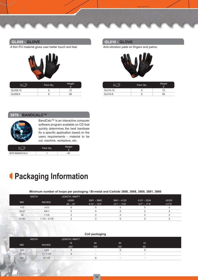
A thin PU material gives user better touch and feel. Anti-vibration pads on fingers and palms.
BandCalc™ is an interactive computer software program available on CD that quickly determines the best bandsaw for a specific application based on the users requirements - material to be cut, machine, workpiece, etc.
Packaging InformationMinimum number of loops per packaging / Bi-metal and Carbide 3866, 3868, 3869, 3881, 3860WIDTH LENGTH, MM/FT
MM INCHES≤3000
≤9’ – 10”3001 – 36609’10” – 12’0”
3661 – 412012’1” – 13’6”
4121 – 533413’7” – 17’5”
≥5335≥17’5”
≤13 ≤1/2 5 5 5 5 516-27 5/8-1 5 5 2 2 2
34 1-1/4 2 2 2 2 241-80 1-1/2 – 3-1/8 2 2 2 2 2
Coil packagingWIDTH LENGTH, MM/FT
MM INCHES76
250’50
164’30
100’1550’
≤20 ≤3/4 X - X X27-34 1 – 1-1/4 X - - -
≥41 ≥1-1/2 - X - -
Pack Qty. Weightg
GL008-10 6 72GL008-8 6 69
Pack Qty. Weightg
GL010-10 6 72GL010-8 6 69
Pack Qty. Weightg
3870-BANDCALC 1 45
GL008 - GLOVE GL010 - GLOVE
3870 - BANDCALC™

37
D = y + φ (x º / d2) D = y + φ (x º / d2)D = y + φ (x º / d2)
ø 34 H. 23 (ø 8 +Ω.1977)ø 30 H. 29 (ø 12 +Ω.1981)
POWER HACKSAWSHINTS FOR POWER HACKSAWING WITH SANDFLEX® HACKSAW BLADES
Tension the blade more than conventional HSS blades. Re-tensioning may be necessary
Run in a new blade for a few minutes at reduced feed
Set the right feed by checking the chips. They should be round, fine and spiral shaped. Burned or blued chips mean that the feed is too high
Thin chips mean that the feed is too low Use the recommended coolant Make sure that the workpiece is securely clamped
Choose a wider and thicker blade for steel grades with poor machinability. The material wastage will be higher, but the risk of crooked kerfs will be reduced
Never use a new blade to saw in an existing kerf Avoid sawing into sharp edges and corners Always start the saw with the blade clear of the workpiece. The teeth should not be touching the workpiece when the machine is started
Keep the machine in good condition
BLADE TENSIONINGCorrect blade tension is essential for ensuring a straight kerf and a long useful life of the blade. If the tension is too low, the blade will bend upwards or twist, giving rise to high stresses, heavy wear of the blade and uneven, crooked kerfs. Excessive tension causes high stresses in the blade and saw frame. In such cases, the blade will generally break, but the frame may also be damaged, particularly if a heavy blade is used.
The only reliable way of tensioning the blade is to use the Bahco blade tensionmeter. This is an instrument mounted on the saw blade that measures its elongation when tension is applied.There is a recommended value for every blade.
Fix the blade in the saw frame with the tooth points facing in the direction of sawing but do not tension the blade
Check that the blade lies absolutely flat against the blade holder
Secure the blade-tension gauge to the saw blade Turn the tensioning nut until the scale on the blade -tension gauge shows the recommended tension
If you do not have a blade-tension gauge, follow the blade tensioning recommendations of the manufacturer

38
D = y + φ (x º / d2)D = y + φ (x º / d2) D = y + φ (x º / d2)
ø 34 H. 23 (ø 8 +Ω.1977)ø 30 H. 29 (ø 12 + Ω.1981 )
The correct stroke rate for a given job depends on the machinability of the material. For maximum blade life the stroke rate should be low and the feed pressure moderate. As a general rule, harder materials call for a lower stroke rate and higher feed pressure.
STROKE RATE
FEED
Standard Bahco power hacksaw blades are supplied with 4, 6, 8, 10 and 14 teeth per inch (blades for Kasto® machines are also available with 2 and 3 teeth per inch). For power sawing it is particularly important to select the right number of teeth per inch. A useful rule of thumb is that at least three teeth should be engaged at any one time.
Tooth choice will depend on the properties and dimensions of the material to be sawn. Thin stock requires more teeth per inch to prevent them from digging in and being broken off. Soft materials such as aluminium call for large chip spaces, i.e. a large pitch, to prevent the chips from clogging the teeth of the blade and interfering with sawing.
MATERIALS AND TOOTHING
The cutting capacity of a hacksaw depends – among other things – on a combination of feed pressure and stroke rate. Maximizing feed pressure and stroke rate certainly increases capacity, but it also increases the danger of a crooked cut and leads to faster blade wear. Our recommendation is to use a high feed pressure but to reduce the stroke rate.It is not possible to provide exact feed pressures since conditions vary on different machines. Excessive feed pressure may give rise to tooth stripping, skew cutting and even blade breakage. Insufficient feed pressure may cause the saw teeth to slide on the workpiece without cutting properly, resulting in overheating, softening and abnormally rapid wear.By studying the workpiece, the blade and thechips, you can often tell whether you havechosen a suitable pressure. Here are some clues:If machine vibration is abnormal, feed pressure is too high.If the chips are burnt, feed pressure is too high.If tooth cracks appear, feed pressure is too high.Fine, powdery chips indicate that feed pressure is too low.The teeth may also show signs of overheatingand dulling.Fine curled chips indicate the optimal feed pressure.
A new blade should always be “run in” by sawing with reduced feed pressure for a few minutes to ensure a longer blade life.
39
D = y + φ (x º / d2) D = y + φ (x º / d2)D = y + φ (x º / d2)
ø 34 H. 23 (ø 8 +Ω.1977)ø 30 H. 29 (ø 12 +Ω.1981)
L x W x Tmm
Weightg
3809-300-25-1.25-10 10 300 x 25 x 1.25 10 733809-300-25-1.25-14 10 300 x 25 x 1.25 14 733809-300-32-1.60-6 10 300 x 32 x 1.60 6 1203809-300-32-1.60-10 10 300 x 32 x 1.60 10 1203809-350-25-1.25-6 10 350 x 25 x 1.25 6 883809-350-25-1.25-10 10 350 x 25 x 1.25 10 883809-350-25-1.25-14 10 350 x 25 x 1.25 14 883809-350-32-1.60-4 10 350 x 32 x 1.60 4 1453809-350-32-1.60-6 10 350 x 32 x 1.60 6 1453809-350-32-1.60-8 10 350 x 32 x 1.60 8 1453809-350-32-1.60-10 10 350 x 32 x 1.60 10 1453809-350-32-1.60-14 10 350 x 32 x 1.60 14 1453809-350-32-2.00-4 10 350 x 32 x 2.00 4 1593809-350-32-2.00-6 10 350 x 32 x 2.00 6 1593809-350-32-2.00-10 10 350 x 32 x 2.00 10 1593809-350-38-2.00-4 10 350 x 38 x 2.00 4 2043809-350-38-2.00-6 10 350 x 38 x 2.00 6 2043809-350-38-2.00-10 10 350 x 38 x 2.00 10 2043809-400-25-1.25-10 10 400 x 25 x 1.25 10 1083809-400-25-1.25-14 10 400 x 25 x 1.25 14 1083809-400-32-1.60-4 10 400 x 32 x 1.60 4 1603809-400-32-1.60-6 10 400 x 32 x 1.60 6 1603809-400-32-1.60-8 10 400 x 32 x 1.60 8 1603809-400-32-1.60-10 10 400 x 32 x 1.60 10 1603809-400-32-1.60-14 10 400 x 32 x 1.60 14 1603809-400-32-2.00-4 10 400 x 32 x 2.00 4 1843809-400-32-2.00-6 10 400 x 32 x 2.00 6 1843809-400-32-2.00-8 10 400 x 32 x 2.00 8 1843809-400-32-2.00-10 10 400 x 32 x 2.00 10 1843809-400-38-2.00-4 10 400 x 38 x 2.00 4 2193809-400-38-2.00-6 10 400 x 38 x 2.00 6 2193809-400-38-2.00-10 10 400 x 38 x 2.00 10 2193809-425-32-1.60-10 10 425 x 32 x 1.60 10 1703809-450-32-1.60-4 10 450 x 32 x 1.60 4 1773809-450-32-1.60-6 10 450 x 32 x 1.60 6 1773809-450-32-1.60-10 10 450 x 32 x 1.60 10 1773809-450-32-1.60-14 10 450 x 32 x 1.60 14 1773809-450-32-2.00-4 10 450 x 32 x 2.00 4 2093809-450-32-2.00-6 10 450 x 32 x 2.00 6 2093809-450-32-2.00-10 10 450 x 32 x 2.00 10 2093809-450-38-2.00-4 10 450 x 38 x 2.00 4 2493809-450-38-2.00-6 10 450 x 38 x 2.00 6 2493809-450-38-2.00-8 10 450 x 38 x 2.00 8 2493809-450-38-2.00-10 10 450 x 38 x 2.00 10 2493809-450-45-2.25-4 10 450 x 45 x 2.25 4 3583809-450-45-2.25-6 10 450 x 45 x 2.25 6 3583809-475-45-2.25-6 10 475 x 45 x 2.25 6 3783809-500-38-2.00-4 10 500 x 38 x 2.00 4 304
L x W x Tmm
Weightg
3809-500-38-2.00-6 10 500 x 38 x 2.00 6 3043809-500-38-2.00-10 10 500 x 38 x 2.00 10 3043809-500-45-2.25-4 10 500 x 45 x 2.25 4 3983809-500-45-2.25-6 10 500 x 45 x 2.25 6 3983809-500-50-2.50-4 10 500 x 50 x 2.50 4 5133809-500-50-2.50-6 10 500 x 50 x 2.50 6 5133809-500-50-2.50-8 10 500 x 50 x 2.50 8 5133809-525-38-2.00-6 10 525 x 38 x 2.00 6 3143809-525-38-2.00-10 10 525 x 38 x 2.00 10 3143809-525-45-2.25-4 10 525 x 45 x 2.25 4 4233809-525-45-2.25-6 10 525 x 45 x 2.25 6 4233809-550-45-2.25-4 10 550 x 45 x 2.25 4 4333809-550-45-2.25-6 10 550 x 45 x 2.25 6 4333809-550-50-2.50-4 10 550 x 50 x 2.50 4 5533809-550-50-2.50-6 10 550 x 50 x 2.50 6 5533809-575-45-2.25-4 10 575 x 45 x 2.25 4 4533809-575-50-2.50-4 10 575 x 50 x 2.50 4 5683809-575-50-2.50-6 10 575 x 50 x 2.50 6 5683809-600-45-2.25-4 10 600 x 45 x 2.25 4 4783809-600-45-2.25-6 10 600 x 45 x 2.25 6 4783809-600-50-2.50-3 10 600 x 50 x 2.50 3 5883809-600-50-2.50-4 10 600 x 50 x 2.50 4 5883809-600-50-2.50-6 10 600 x 50 x 2.50 6 5883809-650-50-2.50-4 5 650 x 50 x 2.50 4 6343809-650-50-2.50-6 5 650 x 50 x 2.50 6 6343809-700-50-2.50-4 5 700 x 50 x 2.50 4 6793809-700-50-2.50-6 5 700 x 50 x 2.50 6 6793809-750-50-2.50-4 5 750 x 50 x 2.50 4 690
L x W x T Weightg
3809-400-32-2.00-6-KA 10 400 x 32 x 2.00 6 1843809-450-38-2.00-4-KA 10 450 x 38 x 2.00 4 2493809-450-38-2.00-6-KA 10 450 x 38 x 2.00 6 2493809-450-38-2.00-10-KA 10 450 x 38 x 2.00 10 2493809-500-45-2.25-6-KA 10 500 x 45 x 2.25 6 3983809-500-50-2.50-4-KA 10 500 x 50 x 2.50 4 5133809-500-50-2.50-6-KA 10 500 x 50 x 2.50 6 5133809-550-50-2.50-4-KA 10 550 x 50 x 2.50 4 5533809-550-50-2.50-6-KA 10 550 x 50 x 2.50 6 5533809-575-50-2.50-3-KA 10 575 x 50 x 2.50 3 5683809-575-50-2.50-4-KA 10 575 x 50 x 2.50 4 5683809-575-50-2.50-6-KA 10 575 x 50 x 2.50 6 5683809-575-50-2.50-10-KA 10 575 x 50 x 2.50 10 5683809-600-50-2.50-4-KA 10 600 x 50 x 2.50 4 5883809-600-50-2.50-6-KA 10 600 x 50 x 2.50 6 5883809-650-50-2.50-3-KA 5 650 x 50 x 2.50 3 6343809-650-50-2.50-4-KA 5 650 x 50 x 2.50 4 6343809-650-50-2.50-6-KA 5 650 x 50 x 2.50 6 6343809-700-50-2.50-3-KA 5 700 x 50 x 2.50 3 6793809-700-50-2.50-4-KA 5 700 x 50 x 2.50 4 6793809-700-50-2.50-6-KA 5 700 x 50 x 2.50 6 679
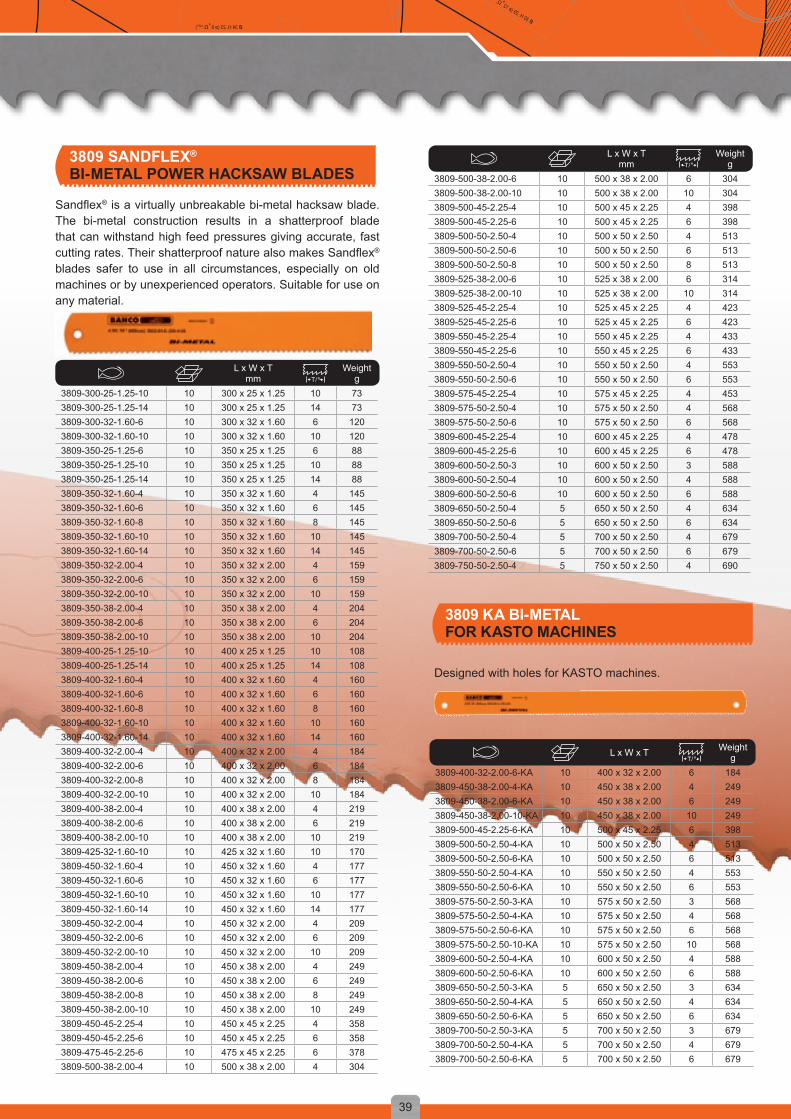
Sandflex® is a virtually unbreakable bi-metal hacksaw blade. The bi-metal construction results in a shatterproof blade that can withstand high feed pressures giving accurate, fast cutting rates. Their shatterproof nature also makes Sandflex® blades safer to use in all circumstances, especially on old machines or by unexperienced operators. Suitable for use on any material.
Designed with holes for KASTO machines.
3809 SANDFLEX®
BI-METAL POWER HACKSAW BLADES
3809 KA BI-METALFOR KASTO MACHINES

40
D = y + φ (x º / d2)D = y + φ (x º / d2) D = y + φ (x º / d2)
ø 34 H. 23 (ø 8 +Ω.1977)ø 30 H. 29 (ø 12 + Ω.1981 )
HOLESAWS DESIGNED FOR PROFESSIONAL USE
Bahco holesaws set the standard in precision, quality, durability and versatility. So no matter what you are cutting, we have the holesaws and arbors to tackle the job, time after time.
Every aspect of the holesaws is engineered to improve productivity and craftsmanship from the design of the cutting edges to the technologies used to produce the holesaws. The holesaws fit standard portable drills and drill presses.
Power Driver™ arbors stabilise the sawing operationand distribute efficiently the cutting forces on the saw.
Holesaws can be easily fitted or removed with the
arbor fixed in the power drillHSS
pilot drill
Hardened body for maximum strength
Slots for removal of cores
Sandflex® bi-metal body for increased safety
Ejector spring to facilitate core removal
Hardened HSS toothing

41
D = y + φ (x º / d2) D = y + φ (x º / d2)D = y + φ (x º / d2)
ø 34 H. 23 (ø 8 +Ω.1977)ø 30 H. 29 (ø 12 +Ω.1981)
The true quality of a holesaw is not found in its colour or its packaging, but in the choice of material, the design, the tooth profile and last but not least, the construction of the arbor. On the surface many holesaws may look identical but put them to the test and you will quickly realise that the differences are considerable.
In Bahco’s saw laboratory we test every holesaw in the market place. We know where the differences and similarities lie. There is a clear performance difference between professional quality tools and other alternatives that are used in a non-professional environment.
Bahco Sandflex® holesaws have a 4/6 tooth pitch. By varying the distance between the teeth (vari-pitch) a smoother cut is achieved with less vibration, even in difficult-to-cut materials.
The aggressive tooth shape cuts fast, whilst the large tooth gullets and large tooth set make removal more efficient.
All VIP holesaws are manufactured from Sandflex® bi-metal steel with hardened teeth of high-alloyed, high-speed steel (HSS). Bi-metal gives increased safety
as it will not shatter even if overloaded. It enables the optimum cutting performance in all machinable materials from wood to stainless steel, and it gives increased resistance to wear.
Create clean, accurate holes in most machinable materials
High-speed cutting edge is laser welded to tough steel alloy back
Knockout holes allow easy core removal
Diameters from 9/16” to 8.1/4” (14 mm to 210 mm)
Cutting depth for all diameters is 1 1/2” (38 mm)
SANDFLEX® HOLESAWS
LONG LIFE, FAST CUTS AND REDUCED EFFORT
On carbide-tipped (CT) holesaws tooth tips consist of a carbide ”round rod” which is fusion welded to the back material. The tip is then ground to its final shape with 5° positive cutting angle.
CT holesaws offer the new capability to cut holes in light concrete, brick, tile, reinforced plastics and other abrasive, non-ferrous materials.
Carbide saws cut clean holes in ceramics, brick, slate, laminate, fibreglass, hardwood...Knockout holes allow easy core removalDiameters from 9/16” to 8.1/4” (14 mm to 152 mm)Cutting depth for all diameters is 1 1/2” (38 mm)
CARBIDE HOLESAWS

ADP
ES
DP-75
DP-100
42
D = y + φ (x º / d2)D = y + φ (x º / d2) D = y + φ (x º / d2)
ø 34 H. 23 (ø 8 +Ω.1977)ø 30 H. 29 (ø 12 + Ω.1981 )
HOLESAW SYSTEMA complete line of saws, arbors, drive plates and accessories – everything you need to make perfect holes from 9/16” to 8.1/4” (14 mm to 210 mm).
Designed as a fully interchangeable system, this full line of arbors, arbor extensions, pilot drills, drive plates, ejector springs and adapters maximizes the performance and flexibility of Bahco holesaws.
Select an appropriate arbor according to holesaw size and chuck size of drilling equipment.
3834-ARBR-730, for holesaws 14-30 mm, is an arbor with triangular shank and round arbor body. For sturdier design and easier removal of 14-30 mm holesaws select arbors with hexagonal shank and hexagonal body, i.e. 3834-ARBR-630, -930, -1130.
The design of arbors for 32-210 mm holesaws, 3834-ARBR-9100, -11152 and -16152 Power Driver™, eliminates play and increases the strength of the holesaw by redistributing the load from the thread to the solid cap. The Power Driver™ arbors must be used with hand held
machines and when operating with high workload in static machines.
QC arbors have a quick-change mechanism so that tools are not required when changing holesaws.
All arbors are hardened for maximum strength.
Large arbors, for holesaws 32-210 mm, have drive pins to transfer larger cutting force from power unit to the holesaw. We recommend not using arbors with 9 mm (11/32”) shank for holesaws above size 100 mm (4”). An HSS Pilot drill (3834-DRL) is included with all arbors. When cutting abrasive materials we recommend the use of carbide-tipped pilot drill, 3834-DRL-CT.
Carbide-tipped
holesawsBi-metal
holesaws
Actual lenght is 12"
With hexagon shank
Triangular shank

43
D = y + φ (x º / d2) D = y + φ (x º / d2)D = y + φ (x º / d2)
ø 34 H. 23 (ø 8 +Ω.1977)ø 30 H. 29 (ø 12 +Ω.1981)
Bahco Sandflex® bi-metal holesaws perform well in materials such as wood, plastics, non ferrous and ferrous steel including stainless steel. Fit all power drills, both stationary and portable. Knockout holes allow easy removal of cores. Cutting depth max. 38 mm (1 1/2”) 4/6 teeth per inch. Every holesaw is packed in a cardboard box with an instruction leaflet enclosed. Max. holesize = nominal holesaw size +1.5 mm/-0.0 mm extra large size. 168 mm and 210 mm 6 TPI (R6). Cutting depth max. 38 mm. 177 mm 4/6 TPI. Cutting depth max 50 mm.
3830 SANDFLEX® BI-METAL HOLESAWS
3830-14-VIP 6 14 9/16 203830-16-VIP 6 16 5/8 203830-17-VIP 6 17 11/16 303830-19-VIP 6 19 3/4 303830-20-VIP 6 20 25/32 303830-21-VIP 6 21 13/16 403830-22-VIP 6 22 7/8 403830-24-VIP 6 24 15/16 553830-25-VIP 6 25 1 553830-27-VIP 6 27 1 1/16 703830-29-VIP 6 29 1 1/8 703830-30-VIP 6 30 1 3/16 703830-32-VIP 6 32 1 1/4 703830-33-VIP 6 33 1 5/16 703830-35-VIP 6 35 1 3/8 703830-37-VIP 6 37 1 7/16 803830-38-VIP 6 38 1 1/2 803830-40-VIP 6 40 1 9/16 803830-41-VIP 6 41 1 5/8 803830-43-VIP 6 43 1 11/16 903830-44-VIP 6 44 1 3/4 1003830-46-VIP 6 46 1 13/16 1003830-48-VIP 6 48 1 7/8 1003830-50-VIP 6 50 1 9/10 1203830-51-VIP 6 51 2 1203830-52-VIP 4 52 2 1/16 1203830-54-VIP 4 54 2 1/8 1403830-55-VIP 4 55 2 1/12 1603830-56-VIP 4 56 2 3/16 1403830-57-VIP 4 57 2 1/4 140
3830-59-VIP 4 59 2 5/16 1403830-60-VIP 4 60 2 3/8 1603830-62-VIP 4 62 2 7/16 1603830-64-VIP 4 64 2 1/2 1803830-65-VIP 4 65 2 9/16 1803830-67-VIP 4 67 2 5/8 2003830-68-VIP 4 68 2 11/16 2203830-70-VIP 4 70 2 3/4 2203830-73-VIP 4 73 2 7/8 2203830-76-VIP 4 76 3 2403830-79-VIP 4 79 3 1/8 2603830-83-VIP 4 83 3 1/4 2603830-86-VIP 4 86 3 3/8 2603830-89-VIP 4 89 3 1/2 2703830-92-VIP 4 92 3 5/8 2703830-95-VIP 4 95 3 3/4 2703830-98-VIP 4 98 3 7/8 3003830-102-VIP 4 102 4 3203830-105-VIP 4 105 4 1/8 3203830-108-VIP 4 108 4 1/4 3503830-111-VIP 4 111 4 3/8 3503830-114-VIP 4 114 4 1/2 3603830-121-VIP 1 121 4 3/4 4103830-127-VIP 1 127 5 5203830-133-VIP 1 133 5 1/4 5603830-140-VIP 1 140 5 1/2 5603830-146-VIP 1 146 5 3/4 5703830-152-VIP 1 152 6 6103830-177-HIGH 1 177 7 13403830-210 1 210 8 1/4 750
Pack Qty. mm inch Weightg Pack Qty. mm inch Weight
g
BI-METAL
44
D = y + φ (x º / d2)D = y + φ (x º / d2) D = y + φ (x º / d2)
ø 34 H. 23 (ø 8 +Ω.1977)ø 30 H. 29 (ø 12 + Ω.1981 )
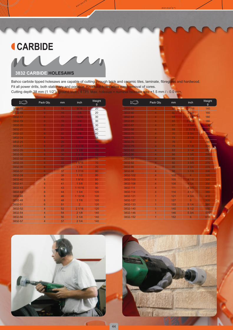
Bahco carbide tipped holesaws are capable of cutting through brick and ceramic tiles, laminate, fibreglass and hardwood.Fit all power drills, both stationary and portable. Knockout holes allow easy removal of cores.Cutting depth 38 mm (1 1/2”), ground teeth, 4 TPI. Max. holesize = nominal holesaw size +1.5 mm / - 0.0 mm.
3832 CARBIDE HOLESAWS
3832-14 6 14 9/16 203832-16 6 16 5/8 203832-17 6 17 11/16 303832-19 6 19 3/4 303832-20 6 20 6/8 303832-21 6 21 13/16 403832-22 6 22 7/8 403832-24 6 24 15/16 553832-25 6 25 1 553832-27 6 27 1 1/16 703832-29 6 29 1 1/8 703832-30 6 30 1 3/16 703832-32 6 32 1 1/4 703832-33 6 33 1 5/16 703832-35 6 35 1 3/8 703832-37 6 37 1 7/16 803832-38 6 38 1 1/2 803832-40 6 40 1 9/16 803832-41 6 41 1 5/8 803832-43 6 43 1 11/16 903832-44 6 44 1 3/4 1003832-46 6 46 1 13/16 1003832-48 6 48 1 7/8 1003832-51 6 51 2 1203832-52 4 52 2 1/16 1203832-54 4 54 2 1/8 1403832-56 4 56 2 1/4 1403832-57 4 57 2 1/4 140
3832-59 4 59 2 5/16 1403832-60 4 60 2 3/8 1603832-64 4 64 2 1/2 1803832-65 4 65 2 9/16 1803832-67 4 67 2 5/8 2003832-68 4 68 2 11/16 2203832-70 4 70 2 3/4 2203832-73 4 73 2 7/8 2203832-76 4 76 3 2403832-79 4 79 3 1/8 2603832-83 4 83 3 1/4 2603832-86 4 86 3 3/8 2603832-89 4 89 3 1/2 2703832-92 4 92 3 5/8 2703832-95 4 95 3 3/4 2703832-98 4 98 3 7/8 3003832-102 4 102 4 3203832-105 4 105 4 1/8 3203832-108 4 108 4 1/4 3503832-111 4 111 4 3/8 3503832-114 4 114 4 1/2 3603832-121 1 121 4 3/4 4103832-127 1 127 5 5203832-133 1 133 5 1/4 5603832-140 1 140 5 1/2 5603832-146 1 146 5 3/4 5703832-152 1 152 6 610
Pack Qty. mm inch Weightg Pack Qty. mm inch Weight
g
CARBIDE
45
D = y + φ (x º / d2) D = y + φ (x º / d2)D = y + φ (x º / d2)
ø 34 H. 23 (ø 8 +Ω.1977)ø 30 H. 29 (ø 12 +Ω.1981)
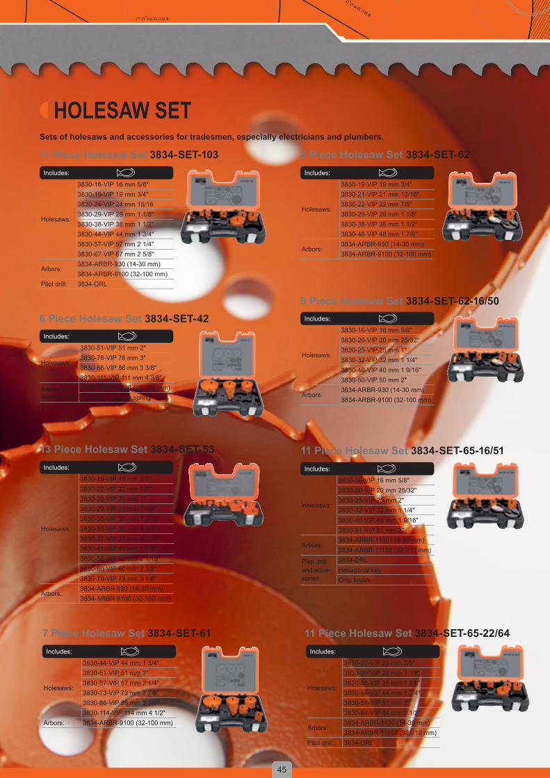
Includes:
Holesaws:
3830-22-VIP 22 mm 7/8"3830-29-VIP 29 mm 1 1/8"3830-35-VIP 35 mm 1 3/8"3830-44-VIP 44 mm 1 3/4"3830-51-VIP 51 mm 2"3830-64-VIP 64 mm 2 1/2"
Arbors:3834-ARBR-1130 (14-30 mm)3834-ARBR-11152 (32-210 mm)
Pilot drill: 3834-DRL
Includes:
Holesaws:
3830-44-VIP 44 mm 1 3/4"3830-51-VIP 51 mm 2"3830-57-VIP 57 mm 2 1/4"3830-73-VIP 73 mm 2 7/8"3830-86-VIP 86 mm 3 3/8"3830-114-VIP 114 mm 4 1/2"
Arbors: 3834-ARBR-9100 (32-100 mm)
Includes:
Holesaws:
3830-19-VIP 19 mm 3/4"3830-22-VIP 22 mm 7/8"3830-25-VIP 25 mm 1"3830-29-VIP 29 mm 1 1/8"3830-30-VIP 30 mm 1 3/16"3830-35-VIP 35 mm 1 3/8"3830-37-VIP 37 mm 1 7/16"3830-41-VIP 41 mm 1 5/8"3830-52-VIP 52 mm 2 1/16"3830-60-VIP 60 mm 2 3/8"3830-79-VIP 79 mm 3 1/8"
Arbors:3834-ARBR-930 (14-30 mm)3834-ARBR-9100 (32-100 mm)
Includes:
Holesaws:
3830-16-VIP 16 mm 5/8"3830-20-VIP 20 mm 25/32"3830-25-VIP 25 mm 2"3830-32-VIP 32 mm 1 1/4"3830-40-VIP 40 mm 1 9/16"3830-51-VIP 51 mm 2"
Arbors:3834-ARBR-1130 (14-30 mm)3834-ARBR-11152 (32-210 mm)
Pilot drill and acce-sories:
3834-DRLHexagonal keyChip brush
Includes:
Holesaws:
3830-51-VIP 51 mm 2"3830-76-VIP 76 mm 3"3830-86-VIP 86 mm 3 3/8"3830-111-VIP 111 mm 4 3/8"
Arbors and accessories:
3834-ARBR-9100 (32-100 mm)3834-ES - Ejector spring
Includes:
Holesaws:
3830-16-VIP 16 mm 5/8"3830-20-VIP 20 mm 25/32"3830-25-VIP 25 mm 1"3830-32-VIP 32 mm 1 1/4"3830-40-VIP 40 mm 1 9/16"3830-50-VIP 50 mm 2"
Arbors:3834-ARBR-930 (14-30 mm)3834-ARBR-9100 (32-100 mm)
Includes:
Holesaws:
3830-19-VIP 19 mm 3/4"3830-21-VIP 21 mm 13/16"3830-22-VIP 22 mm 7/8"3830-29-VIP 29 mm 1 1/8"3830-38-VIP 38 mm 1 1/2"3830-48-VIP 48 mm 1 7/8"
Arbors:3834-ARBR-930 (14-30 mm)3834-ARBR-9100 (32-100 mm)
Includes:
Holesaws:
3830-16-VIP 16 mm 5/8"3830-19-VIP 19 mm 3/4"3830-24-VIP 24 mm 15/163830-29-VIP 29 mm 1 1/8"3830-38-VIP 38 mm 1 1/2"3830-44-VIP 44 mm 1 3/4"3830-57-VIP 57 mm 2 1/4"3830-67-VIP 67 mm 2 5/8"
Arbors:3834-ARBR-930 (14-30 mm)3834-ARBR-9100 (32-100 mm)
Pilot drill: 3834-DRL
Sets of holesaws and accessories for tradesmen, especially electricians and plumbers.
11 Piece Holesaw Set 3834-SET-103 8 Piece Holesaw Set 3834-SET-62
6 Piece Holesaw Set 3834-SET-428 Piece Holesaw Set 3834-SET-62-16/50
13 Piece Holesaw Set 3834-SET-53 11 Piece Holesaw Set 3834-SET-65-16/51
7 Piece Holesaw Set 3834-SET-61 11 Piece Holesaw Set 3834-SET-65-22/64
HOLESAW SET

46
D = y + φ (x º / d2)D = y + φ (x º / d2) D = y + φ (x º / d2)
ø 34 H. 23 (ø 8 +Ω.1977)ø 30 H. 29 (ø 12 + Ω.1981 )
Kit 13 Piece 3834-SET-95Includes:
Holesaws:
3830-16-VIP 16 mm 5/8"3830-19-VIP 19 mm 3/4"3830-22-VIP 22 mm 7/8"3830-29-VIP 29 mm 1 1/8"3830-35-VIP 35 mm 1 3/8"3830-44-VIP 44 mm 1 3/4"3830-52-VIP 52 mm 2 1/16"3830-57-VIP 57 mm 2 1/4"3830-64-VIP 64 mm 2 1/2"
Arbors: 3834-ARBR-1130 (14-30 mm)3834-ARBR-11152 (32-210 mm)
Pilot drill and acce-sories:
3834-DRLHexagonal keyChip brush
Kit 12 Piece 3834-SET-86Includes:
Holesaws:
3830-25-VIP 25 mm 1"3830-32-VIP 32 mm 1 1/4"3830-35-VIP 35 mm 1 3/8"3830-51-VIP 51 mm 2"3830-54-VIP 54 mm 2 1/8"3830-76-VIP 76 mm 3"3830-92-VIP 92 mm 3 5/8"3830-114-VIP 114 mm 4 1/2"
Arbors:3834-ARBR-1130 (14-30 mm)3834-ARBR-11152 (32-210 mm)
Pilot drill and accesories:
3834-DRLHexagonal key
Adapter: 3834-ADP
Kit 9 Piece 3834-SET-73Includes:
Holesaws:
3830-16-VIP 16 mm 5/8"3830-22-VIP 22 mm 7/8"3830-51-VIP 51 mm 2"3830-57-VIP 57 mm 2 1/4"3830-73-VIP 73 mm 2 7/8"3830-76-VIP 76 mm 3"3830-92-VIP 92 mm 3 5/8"
Arbors:3834-ARBR-930 (14-30 mm)3834-ARBR-9100 (32-100 mm)
Kit 11 Piece 3834-SET-92Includes:
Holesaws:
3830-16-VIP 16 mm 5/8"3830-22-VIP 22 mm 7/8"3830-25-VIP 25 mm 1"3830-29-VIP 29 mm 1 1/8"3830-32-VIP 32 mm 1 1/4"3830-41-VIP 41 mm 1 5/8"3830-51-VIP 51 mm 2"3830-73-VIP 73 mm 2 7/8"3830-83-VIP 83 mm 3 1/4"
Arbors: 3834-ARBR-930 (14-30 mm)3834-ARBR-9100 (32-100 mm)
Kit 13 Piece 3834-SET-94Includes:
Holesaws:
3830-16-VIP 16 mm 5/8"3830-19-VIP 19 mm 3/4"3830-22-VIP 22 mm 7/8"3830-25-VIP 25 mm 1"3830-30-VIP 30 mm 1 3/16"3830-35-VIP 35 mm 1 3/8"3830-41-VIP 41 mm 1 5/8"3830-51-VIP 51 mm 2"3830-67-VIP 67 mm 2 5/8"
Arbors: 3834-ARBR-1130 (14-30 mm)3834-ARBR-11152 (32-210 mm)
Accesories: Hexagonal keyChip brush
Kit 10 Piece 3834-SET-73-22/68Includes:
Holesaws:
3830-22-VIP 22 mm 7/8"3830-29-VIP 29 mm 1 1/8"3830-35-VIP 35 mm 1 3/8"3830-44-VIP 44 mm 1 3/4"3830-51-VIP 51 mm 2"3830-64-VIP 64 mm 2 1/2"3830-68-VIP 68 mm 2 11/16"
Arbors:3834-ARBR-1130 (14-30 mm)3834-ARBR-11152 (32-210 mm)
Pilot drill: 3834-DRL
Kit 14 Piece 3834-SET-87Includes:
Holesaws:
3830-19-VIP 19 mm 3/4"3830-22-VIP 22 mm 7/8"3830-29-VIP 29 mm 1 1/8"3830-38-VIP 38 mm 1 1/2"3830-43-VIP 43 mm 1 3/4"3830-48-VIP 48 mm 1 7/8"3830-52-VIP 52 mm 2 1/16"3830-65-VIP 65 mm 2 9/16"
Arbors: 3834-ARBR-930 (14-30 mm)3834-ARBR-9100 (32-100 mm)
Pilot drill and acce-sories:
3834-DRL3834-ESHexagonal keyChip brush
Kit 9 Piece 3834-SET-72Includes:
Holesaws:
3830-19-VIP 19 mm 3/4"3830-22-VIP 22 mm 7/8"3830-29-VIP 29 mm 1 1/8"3830-35-VIP 35 mm 1 3/8"3830-44-VIP 44 mm 1 3/4"3830-51-VIP 51 mm 2"3830-64-VIP 64 mm 2 1/2"
Arbors:3834-ARBR-930 (14-30 mm)3834-ARBR-9100 (32-100 mm)
47
D = y + φ (x º / d2) D = y + φ (x º / d2)D = y + φ (x º / d2)
ø 34 H. 23 (ø 8 +Ω.1977)ø 30 H. 29 (ø 12 +Ω.1981)
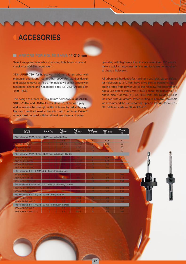
ARBORS FOR HOLES SAWS 14-210 mm
Select an appropriate arbor according to holesaw size andchuck size of drilling equipment.
3834-ARBR-730, for holesaws 14-30 mm, is an arbor with triangular shank and round arbor body. For sturdier design and easier removal of 14-30 mm holesaws select arbors with hexagonal shank and hexagonal body, i.e. 3834-ARBR-630, -930, -1130.
The design of arbors for 32-210 mm holesaws, 3834-ARBR-9100, -11152 and -16152 Power Driver™, eliminates playand increases the strength of the holesaw by redistributingthe load from the thread to the solid cap. The Power Driver™arbors must be used with hand held machines and when
operating with high work load in static machines. QC arborshave a quick change mechanism and tools are not requiredto change holesaws.
All arbors are hardened for maximum strength. Large arbors,for holesaws 32-210 mm, have drive pins to transfer largecutting force from power unit to the holesaw. We recommendnot to use arbors with 9 mm (11/32”) shank for holesawsabove size 100 mm (4”). An HSS Pilot drill (3834-DRL) is included with all arbors. When cutting in abrasive materials we recommend the use of carbide tipped pilot drill, 3834-DRL-CT. pilote en carbure 3834-DRL-CT.
Pack Qty. mm inch mm inchWeight
g
Fits Holesaws 9/16"-1 3/16", 14-30 mm, Industrial Box3834-ARBR-630 1 6.4 1/4 8 5/16 703834-ARBR-730 1 6.4 TRI 1/4 TRI 8 5/16 603834-ARBR-930 1 8.5 11/32 10 3/8 803834-ARBR-1130 1 11.1 7/16 13 1/2 90Fits Holesaws 9/16"-1 3/16", 14-30 mm, Individually Carded3834-ARBR-630-C 1 6.4 1/4 8 5/16 703834-ARBR-730-C 1 6.4 TRI 1/4 TRI 8 5/16 603834-ARBR-930-C 1 8.5 11/32 10 3/8 803834-ARBR-1130-C 1 11.1 7/16 13 1/2 90Fits Holesaws 1 1/4"-8 1/4", 32-210 mm, Industrial Box3834-ARBR-11152 1 11.1 7/16 13 1/2 2603834-ARBR-16152 1 15.4 5/8 20 3/4 3103834-ARBR-11152QC 1 11.1 7/16 13 1/2 250Fits Holesaws 1 1/4"-8 1/4", 32-210 mm, Individually Carded3834-ARBR-11152-C 1 11.1 7/16 13 1/2 2603834-ARBR-11152QC-C 1 11.1 7/16 13 1/2 250Fits Holesaws 1 1/4"-4", 32-100 mm, Industrial Box3834-ARBR-9100 1 8.5 11/32 10 3/8 2503834-ARBR-9100QC 1 8.5 11/32 10 3/8 160Fits Holesaws 1 1/4"-4", 32-100 mm, Individually Carded3834-ARBR-9100-C 1 8.5 11/32 10 3/8 2503834-ARBR-9100QC-C 1 8.5 11/32 10 3/8 160
ACCESORIES

48
D = y + φ (x º / d2)D = y + φ (x º / d2) D = y + φ (x º / d2)
ø 34 H. 23 (ø 8 +Ω.1977)ø 30 H. 29 (ø 12 + Ω.1981 )
OTHER PARTSPilot drill: 3834-DRL. The HSS pilot drill bores a hole in the workpiece before the teeth of the holesaw become engaged, guiding andkeeping the holesaw in the correct position during the sawing operation.3834-DRL fits all arbors. Standard drill in all arbors.Pilot Drill: 3834-DRL-CT. Carbide tipped pilot drill - Multi purpose CT - drill has a high grade carbide tip with special properties,hardness and geometry. It was specially designed to provide one tool to cover many different materials. It enables high cuttingperformance in all machinable material from wood and plastic to brick and concrete. Fits all arbors.
Pack Qty. A mm A inch B mm B inch Weightg
Fits arbors -730, -930, -1130, -9100QC, -11152QC, -16152QC3834-DRL 1 6.35 1/4 81 3 3/16 20Fits arbors -730, -930, -1130, -9100QC, -11152QC, -16152QC3834-DRL-CT 1 6.35 1/4 84 3 5/16 35
Extension: 3834-EXTExtension for difficult to reach applications.
Pack Qty. mm inch mm inchWeight
g
Fits arbors -1130, -11152, -11152QC3834-EXT-1 1 11.1 7/16 330 12 340Fits arbors -930, -91003834-EXT-2 1 8.5 11/32 330 12 340
Pack Qty. Weightg
Fits arbors -630, -730, -930, -11303834-ADP 1 20
Arbor adaptor: 3834-ADPAdapts small arbor thread (1/2”-20 UNF) to accommodatelarge holesaw thread (5/8”-18 UNF). Not recommended forholesaws larger than 44 mm. 19 mm across the flats.Fits holesaw 32-44 mm.
Pack Qty. Weightg
Fits pilot Drill 3834-DRL3834-ES 1 10
Ejector spring: 3834-ESFor pilot drills, to facilitate core removal.

49
D = y + φ (x º / d2) D = y + φ (x º / d2)D = y + φ (x º / d2)
ø 34 H. 23 (ø 8 +Ω.1977)ø 30 H. 29 (ø 12 +Ω.1981)
RECIPROCATING SAWSBahco offers a range of reciprocating sawblades that is up to every cutting task.
Built using the most advanced alloys and tooth designs, Bahco reciprocating sawblades combine high strength (and shatter resistance) with greater cutting power and control.That’s why they let you produce faster, cleaner and more accurate cuts, time after time.
The Bahco line of reciprocating sawblades is truly unique.With three separate types, each is available in a wide range of designs, lengths and toothings. There is a blade that is perfect for every application.
BAHCO CARBIDE BLADES• Tough carbide blade delivers impressive cutting power
and life• Exceptional performance
BAHCO BI-METAL BLADES• Hardened high speed steel teeth provide aggressive
bite into toughest materials• High performance tooth design resistant to chipping• Spring steel backing provides flexibility and resilience to
prevent shattering
QUICK, ACCURATE AND SAFE CUTTING THROUGH A WIDE RANGE OF MATERIALS

50
D = y + φ (x º / d2)D = y + φ (x º / d2) D = y + φ (x º / d2)
ø 34 H. 23 (ø 8 +Ω.1977)ø 30 H. 29 (ø 12 + Ω.1981 )
How to select the perfect blade for the job from Bahco’s comprehensive line of professional grade reciprocating sawblades.
STEP 1: DETERMINE THE RIGHT TOOTHINGBahco reciprocating sawblades feature aggressive, precision-ground teeth. In addition, many bi-metal blades featurevariable teeth spacing. It all adds up to unbeatable sawing performance and versatility. Material type and thickness determine which toothing pattern and TPI will work best.1. Select material and dimension with the help of the material guide2. Choose group of toothings (TPI’s) which can be used for the application
“Difficultapplications
require a specialist blade”
The numbers in the table stands for the number of teeth per inch (TPI).* Wood-cutting blades. Special blades for pure wood cutting** Blades with carbide-tipped teeth for cutting abrasive non-ferrous materialWhile using reciprocating sawblades in wood with embedded nails we recommend a slightly higher TPI than for pure wood cutting.
STEP 2: IDENTIFY AND CHOOSE THE RIGHT BAHCO RECIPROCATING SAW BLADEHere is how to read product codes for Bahco reciprocating awblades.
Example : 3840- 150- 14- ST- 5P
Teeth Per Inch (TPI)
Blade Length in mm
Blade Material
Packaging Quantity: 1, 2, 5, 10, 100 depending on produt
Blade shape: ST = Standard; UST = U-shank SL = Slope; SC = Scroll DSL = Demolition Slope
Material thickness
mm
Metal/Steel
Plastic Laminates/Chipboard
Wood Plaster boards
Ceramics/Glass/Tiles
Bricks/Fibreglass
>50 4/6 4/67”4/6
3**
20-50 5/8 5/868
10
5/868
10
7”5/85/8/10
5/868
10
6**
10-20 8/1214
8/1214
8/1214
8/128/14
8/1214
6**
3-10 18 18 18 8/18 18 GRIT0-3 24 24 24 8/24

51
D = y + φ (x º / d2) D = y + φ (x º / d2)D = y + φ (x º / d2)
ø 34 H. 23 (ø 8 +Ω.1977)ø 30 H. 29 (ø 12 +Ω.1981)
Blade length mm
Blade Thickness mm
5-PACK
3840-100-6-ST-5P 100 1.3 63840-100-10-ST-5P 100 0.9 103840-100-14-ST-5P 100 0.9 143840-100-18-ST-5P 100 0.9 183840-100-24-ST-5P 100 0.9 243840-150-6-ST-5P 150 1.3 63840-150-8/12-ST-5P 150 0.9 8/123840-150-10-ST-5P 150 0.9 103840-150-14-ST-5P 150 0.9 143840-150-18-ST-5P 150 0.9 183840-150-24-ST-5P 150 0.9 243840-228-8/12-ST-5P 228 1.3 8/123840-228-10-ST-5P 228 0.9 103840-228-14-ST-5P 228 0.9 143840-228-18-ST-5P 228 0.9 183840-300-14-ST-5P 300 0.9 143840-300-18-ST-5P 300 0.9 1810-PACK3840-100-6-ST-10P 100 1.3 63840-100-10-ST-10P 100 0.9 103840-100-14-ST-10P 100 0.9 143840-100-18-ST-10P 100 0.9 183840-100-24-ST-10P 100 0.9 243840-150-6-ST-10P 150 1.3 63840-150-8/12-ST-10P 150 0.9 8/123840-150-10-ST-10P 150 0.9 103840-150-14-ST-10P 150 0.9 143840-150-18-ST-10P 150 0.9 183840-150-24-ST-10P 150 0.9 243840-228-8/12-ST-10P 228 1.3 8/123840-228-10-ST-10P 228 0.9 103840-228-14-ST-10P 228 0.9 143840-228-18-ST-10P 228 0.9 183840-300-14-ST-10P 300 0.9 143840-300-18-ST-10P 300 0.9 18100-PACK3840-150-10-ST-100P 150 0.9 103840-150-14-ST-100P 150 0.9 143840-150-18-ST-100P 150 0.9 183840-150-24-ST-100P 150 0.9 243840-150-8/12-ST-100P 150 1.3 8/123840-228-8/12-ST-100P 228 0.9 8/123840-228-10-ST-100P 228 0.9 103840-228-14-ST-100P 228 0.9 143840-228-18-ST-100P 228 0.9 183840-300-14-ST-100P 300 0.9 143840-300-18-ST-100P 300 0.9 18
ST (Standard) For straight and quick cutting of metal, plastic, laminates and wood with nails.Blade length: 100, 150, 228, 253 and 300 mm.Toothing: 6, 8/12, 10, 14, 18 and 24 teeth per inch.
New assortment with improved performance and precision-ground teeth. Virtually unbreakable Sandflex® bi-metal blade for all materials and type of cut. Specially developed for cutting metal.
3840 SANDFLEX® ST/SL/SC
SL (Slope) For all-round cutting of metal, plastic, laminates and wood with nails.Blade length: 150, 228 and 300 mm.Toothing: 5/8, 6 and 8/12 teeth per inch.
Blade length mm
Blade Thickness mm
5-PACK3840-150-5/8-SL-5P 150 1.3 5/83840-228-6-SL-5P 228 1.3 63840-300-6-SL-5P 300 1.3 63840-300-8/12-SL-5P 300 1.3 8/1210-PACK3840-150-5/8-SL-10P 150 1.3 5/83840-228-6-SL-10P 228 1.3 63840-300-6-SL-10P 300 1.3 63840-300-8/12-SL-10P 300 1.3 8/12100-PACK3840-150-5/8-SL-100P 150 1.3 5/8
SC (Scroll) For contour sawing of metal, plastic, laminates, wood with nails.Blade length: 100 and 150 mm.Toothing: 4/6, 10, 14 and 18 teeth per inch.
Blade length mm
Blade Thickness mm
5-PACK3840-100-10-SC-5P 100 0.9 103840-100-14-SC-5P 100 0.9 143840-100-18-SC-5P 100 0.9 183840-150-4/6-SC-5P 150 1.3 4/610-PACK3840-150-4/6-SC-10P 150 1.3 4/6
BI-METAL

52
D = y + φ (x º / d2)D = y + φ (x º / d2) D = y + φ (x º / d2)
ø 34 H. 23 (ø 8 +Ω.1977)ø 30 H. 29 (ø 12 + Ω.1981 )
CARBIDE3846 CARBURE
Blade length: 150, 228 and 300 mm.Toothing: 3 and 6 teeth per inch.
Blade with carbide-tipped teeth. Ideal for demanding building and industrial applications, such as cutting of bricks, porous concrete, Leca, Siporex, fibreglass and plastic laminates.
3846 CARBIDE GRIT
Blade length: 100 to 150 mm.
Blade with carbide grit cutting edge. For precision cutting of extremely hard materials, such as glass, glazed tiles and ceramics.
Blade length mm
Blade Thickness mm
1-PACK3846-150-6-SL-1P 150 0.9 63846-228-3-ST-1P 228 1.3 33846-228-6-ST-1P 228 0.9 63846-300-3-ST-1P 300 1.3 3
Blade length mm
Blade Thickness mm
2-PACK3846-100-G-ST-2P 100 0.93846-150-G-ST-2P 150 0.9
53
D = y + φ (x º / d2) D = y + φ (x º / d2)D = y + φ (x º / d2)
ø 34 H. 23 (ø 8 +Ω.1977)ø 30 H. 29 (ø 12 +Ω.1981)
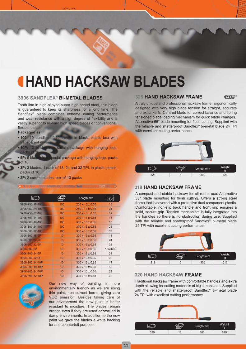
A compact and stable hacksaw for all round use. Alternative 55° blade mounting for flush cutting. Offers a strong steel frame that is covered with a protective dual component plastic.Comfortable, non-slip back handle and front grip ensures a solid, secure grip. Tension mechanism is fully integrated into the handles so there is no obstruction during use. Supplied with the reliable and shatterproof Sandflex® bi-metal blade 24 TPI with excellent cutting performance.
319 HAND HACKSAW FRAME
Traditional hacksaw frame with comfortable handles and extra depth allowing for cutting materials of big dimensions. Supplied with the reliable and shatterproof Sandflex® bi-metal blade 24 TPI with excellent cutting performance.
320 HAND HACKSAW FRAME
Length mm Weightg
320 10 300 820
Tooth line in high-alloyed super high speed steel, this blade is guaranteed to keep its sharpness for a long time. The Sandflex® blade combines extreme cutting performance and wear resistance with a high degree of flexibility and is vastly superior to all-hard high speed blades or conventional, flexible blades. Packaged as:• 100: 10 bundles of 10 blades in black, plastic box with
transparent cover• 10P: 10 blades in a special package with hanging loop,
packs of 10• 5P: 5 blades in a special package with hanging loop, packs
of 10• 3P: 3 blades, 1 each of 18, 24 and 32 TPI, in plastic pouch,
packs of 10• 2P: 2 carded blades, box of 10 packs
Length mm
3906-250-18-100 100 250 x 13 x 0.65 183906-250-24-100 100 250 x 13 x 0.65 243906-250-32-100 100 250 x 13 x 0.65 323906-300-14-100 100 300 x 13 x 0.65 143906-300-18-100 100 300 x 13 x 0.65 183906-300-24-100 100 300 x 13 x 0.65 243906-300-32-100 100 300 x 13 x 0.65 323906-300-18-2P 10 300 x 13 x 0.65 183906-300-24-2P 10 300 x 13 x 0.65 243906-300-32-2P 10 300 x 13 x 0.65 323906-300-3P 10 300 x 13 x 0.65 18/24/323906-300-24-5P 10 300 x 13 x 0.65 243906-300-32-5P 10 300 x 13 x 0.65 323906-300-14-10P 10 300 x 13 x 0.65 143906-300-18-10P 10 300 x 13 x 0.65 183906-300-24-10P 10 300 x 13 x 0.65 243906-300-32-10P 10 300 x 13 x 0.65 32
3906 SANDFLEX® BI-METAL BLADES
Length mm Weightg
325 5 300 720
A truly unique and professional hacksaw frame. Ergonomically designed with very high blade tension for straight, accurate and exact kerfs. Centred blade for correct balance and spring tensioned blade loading mechanism for quick blade changes.Alternative 55° blade mounting for flush cutting. Supplied with the reliable and shatterproof Sandflex® bi-metal blade 24 TPI with excellent cutting performance.
325 HAND HACKSAW FRAME
HAND HACKSAW BLADES
Our new way of painting is more environmentally friendly as we are using thin paint, non solvent borne, giving zero VOC emission. Besides taking care of our environment the new paint is better resistant to moisture. The blades remain orange even if they are used or stocked in damp environments. In addition to the new paint we gave the blades a white backing for anti-counterfeit purposes.
Length mm Weightg
319 5 300 510

54
D = y + φ (x º / d2)D = y + φ (x º / d2) D = y + φ (x º / d2)
ø 34 H. 23 (ø 8 +Ω.1977)ø 30 H. 29 (ø 12 + Ω.1981 )
FILES
THREE DIFFERENT SHAPES & SIZES WITH 12 DIFFERENT INSERTS
PATENTED DESIGN IMPROVES SAFETY AND COMFORT
Our file handles are ergonomically designed, following the Bahco ERGOTM Process, to reduce muscle tension and the risk of injury. The hard polypropylene core, covered with a thermoplastic elastomer, provides a comfortable non-slip grip, and the handle’s smooth contours fit into the hand naturally.
As a safety feature, the handle covers the tang and shoulder completely. This prevents the hand from slipping off the handle onto the file blade. Bahco supplies most popular files complete with a symmetric handle to allow the user to grip it comfortably regardless of which side of the file is used.
ERGONOMIC HANDLES
Non-slip grip. Smooth contours that fit the
hand naturally
Soft parts and thermoplastic elastomer (TPE) for comfortable
non-slip grip Core in Polypropylene Plastic (PP) for improved durability
Patented design incorporates hole for
hanging the tool
Less probability of injuries. Full protection of the
shoulders prevent injuries
Symmetric handle allows use of both sides with the same
level of comfort
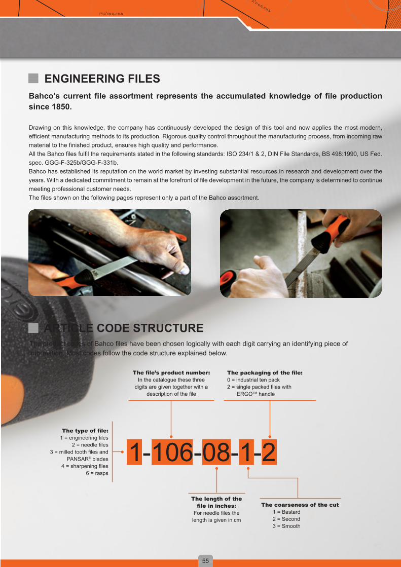
1-106-08-1-2
55
D = y + φ (x º / d2) D = y + φ (x º / d2)D = y + φ (x º / d2)
ø 34 H. 23 (ø 8 +Ω.1977)ø 30 H. 29 (ø 12 +Ω.1981)
Bahco'scurrentfileassortment represents theaccumulatedknowledgeoffileproductionsince 1850.
Drawing on this knowledge, the company has continuously developed the design of this tool and now applies the most modern, efficient manufacturing methods to its production. Rigorous quality control throughout the manufacturing process, from incoming raw material to the finished product, ensures high quality and performance.All the Bahco files fulfil the requirements stated in the following standards: ISO 234/1 & 2, DIN File Standards, BS 498:1990, US Fed.spec. GGG-F-325b/GGG-F-331b.Bahco has established its reputation on the world market by investing substantial resources in research and development over the years. With a dedicated commitment to remain at the forefront of file development in the future, the company is determined to continue meeting professional customer needs.The files shown on the following pages represent only a part of the Bahco assortment.
ENGINEERING FILES
The product codes of Bahco files have been chosen logically with each digit carrying an identifying piece of information. Most codes follow the code structure explained below.
ARTICLE CODE STRUCTURE
The coarseness of the cut 1 = Bastard2 = Second3 = Smooth
The type of file:1 = engineering files
2 = needle files3 = milled tooth files and
PANSAR® blades4 = sharpening files
6 = rasps
The file’s product number:In the catalogue these three
digits are given together with a description of the file
The packaging of the file:0 = industrial ten pack2 = single packed files with
ERGOTM handle
The length of the file in inches:
For needle files the length is given in cm

56
D = y + φ (x º / d2)D = y + φ (x º / d2) D = y + φ (x º / d2)
ø 34 H. 23 (ø 8 +Ω.1977)ø 30 H. 29 (ø 12 + Ω.1981 )
Use: For filing flat surfaces, sharp corners and shoulders as well as for deburring. A double cut file should be used for work in high-alloy tool steels. Also useful for the sharpening of heavy implements. High removal rate.Shape: Edges and surfaces parallel. Surfaces double cut, one edge uncut, one edge single cut.
HAND FILE / 1-100...-2
Pack Qty. A mm B mm C mmcm
Cut Type Weightg
1-100-04-1-2 5 100 12 3.0 17 1 671-100-04-2-2 5 100 12 3.0 22 2 671-100-06-1-2 5 150 16 4.0 13 1 1101-100-06-2-2 5 150 16 4.0 18 2 1101-100-06-3-2 5 150 16 4.0 18 3 1101-100-08-1-2 5 200 20 5.0 10 1 2001-100-08-2-2 5 200 20 5.0 14 2 2001-100-08-3-2 5 200 20 5.0 18 3 2001-100-10-1-2 5 250 25 5.5 9 1 3101-100-10-2-2 5 250 25 5.5 12 2 3101-100-10-3-2 5 250 25 5.5 16 3 3101-100-12-1-2 5 300 30 6.0 8 1 4311-100-12-2-2 5 300 30 6.0 11 2 4311-100-12-3-2 5 300 30 6.0 14 3 431
Use: Useful for all flat filing. Oberg cut gives a high removal rate and smooth surface finish on most materials.Shape: Edges and surfaces parallel. Surfaces single cut, bastard, with chipbreaking teeth. One edge single cut.
HAND FILE “OBERG CUT” / 1-106...-2
Pack Qty. A mm B mm C mmcm
Cut Type Weightg
1-106-08-1-2 5 200 20 5.0 10 1 2001-106-10-1-2 5 250 25 5.5 9 1 3101-106-12-1-2 5 300 30 6.0 8 1 431
Use: For the same jobs as the hand file 100, but is sometimes preferred because its tapered shape enables the user to reach into angles and corners more easily.Shape: Edges tapered towards the point, surfaces parallel. Surfaces double cut, edges single cut. 4” and 6” pointed, 8” and longer semi-pointed.
FLAT FILE / 1-110...-2
Pack Qty. A mm B mm C mmcm
Cut Type Weightg
1-110-06-1-2 5 150 16 4.0 13 1 1101-110-06-2-2 5 150 16 4.0 18 2 1101-110-06-3-2 5 150 16 4.0 22 3 1101-110-08-1-2 5 200 20 5.0 10 1 1801-110-08-2-2 5 200 20 5.0 14 2 1801-110-08-3-2 5 200 20 5.0 18 3 1801-110-10-1-2 5 250 25 5.5 9 1 2701-110-10-2-2 5 250 25 5.5 12 2 2701-110-10-3-2 5 250 25 5.5 16 3 2701-110-12-1-2 5 300 30 6.0 8 1 4311-110-12-2-2 5 300 30 6.0 11 2 4311-110-12-3-2 5 300 30 6.0 14 3 431
Type of cut: 1 = Bastard, 2 = Second, 3 = Smooth.

57
D = y + φ (x º / d2) D = y + φ (x º / d2)D = y + φ (x º / d2)
ø 34 H. 23 (ø 8 +Ω.1977)ø 30 H. 29 (ø 12 +Ω.1981)
Use: For filing narrow grooves and passages, etc. Particularly well suited for filing cuts on keys.Shape: Edges tapered to a point, surfaces parallel. Surfaces double cut, edges single cut.
WARDING FILE / 1-111...-2
Pack Qty. A mm B mm C mmcm
Cut Type Weightg
1-111-06-2-2 5 150 15 1.9 18 2 65
Pack Qty. A mm B mm C mmcm
Cut Type Weightg
1-143-06-1-2 5 150 16 2.7 20 1 901-143-08-1-2 5 200 20 3.3 18 1 1401-143-10-1-2 5 250 25 4.0 16 1 2221-143-12-1-2 5 300 30 5.0 14 1 431
Use: This type of file is suitable both as an engineering file and a sharpening file. It is useful for filing where a smooth finish is important. Also good for polishing and deburring work in lathes. This file is also widely applicable for sharpening tools and implements such as spades, shovels, hoes, scrapers, etc.Shape: Surfaces parallel. Edges tapered towards the point. Surfaces and edges single cut. Bastard cut commonly referred to as Mill bastard.
MILL FILE, 2 FLAT EDGES (TYPE USA) / 1-143...-2
Use: For filing grooves, rectangular holes, internal corners and for fine-adjustment of cutting tools.Shape: Surfaces tapered towards the point. Double cut.
SQUARE FILE / 1-160...-2
Pack Qty. A mm B mmcm
Cut Type Weightg
1-160-04-1-2 5 100 4.5 17 1 421-160-04-2-2 5 100 4.5 22 2 421-160-06-1-2 5 150 6.0 13 1 791-160-06-2-2 5 150 6.0 18 2 791-160-06-3-2 5 150 6.0 22 3 791-160-08-1-2 5 200 8.0 10 1 1321-160-08-2-2 5 200 8.0 14 2 1321-160-08-3-2 5 200 8.0 18 3 1321-160-10-1-2 5 250 10.0 9 1 2121-160-10-2-2 5 250 10.0 12 2 2121-160-10-3-2 5 250 10.0 16 3 2121-160-12-1-2 5 300 12 8 1 3471-160-12-2-2 5 300 12 11 2 347
Use: For deburring and filing angles and internal corners. For filing of holes and large fillets as well as concave surfaces. Its tapered surfaces make it well suited for flat filing.Shape: Equilateral triangle. Tapered towards the point. Double cut surfaces.
THREE SQUARE FILE / 1-170...-2
Pack Qty. A mm B mmcm
Cut Type Weightg
1-170-06-1-2 5 150 11.0 13 1 1031-170-06-2-2 5 150 11.0 18 2 1031-170-06-3-2 5 150 11.0 22 3 1031-170-08-1-2 5 200 15.5 10 1 2031-170-08-2-2 5 200 15.5 14 2 2031-170-08-3-2 5 200 15.5 18 3 2031-170-10-1-2 5 250 17.5 9 1 2821-170-10-2-2 5 250 17.5 12 2 2821-170-10-3-2 5 250 17.5 16 3 2821-170-12-1-2 5 300 19.5 8 1 4201-170-12-2-2 5 300 19.5 11 2 420
Type of cut: 1 = Bastard, 2 = Second, 3 = Smooth.

1-473
1-478
1-476
58
D = y + φ (x º / d2)D = y + φ (x º / d2) D = y + φ (x º / d2)
ø 34 H. 23 (ø 8 +Ω.1977)ø 30 H. 29 (ø 12 + Ω.1981 )
Type of cut: 1 = Bastard, 2 = Second, 3 = Smooth.
Use: For filing concave and flat surfaces and large holes. Suitable for deburring work.Shape: Edges and surfaces tapered towards the point. 4” and 6” fully pointed, 8” and longer semi-pointed. Double cut.
Pack Qty. A mm B mm C mmcm
Cut Type Weightg
1-210-04-2-2 5 100 10.0 3.0 22 2 521-210-06-1-2 5 150 16.0 4.7 13 1 1001-210-06-2-2 5 150 16.0 4.7 18 2 1001-210-06-3-2 5 150 16.0 4.7 22 3 1001-210-08-1-2 5 200 20.5 6.0 10 1 1701-210-08-2-2 5 200 20.5 6.0 14 2 1701-210-08-3-2 5 200 20.5 6.0 18 3 1701-210-10-1-2 5 250 26.5 7.5 9 1 3441-210-10-2-2 5 250 26.5 7.5 12 2 3441-210-10-3-2 5 250 26.5 7.5 16 3 3441-210-12-1-2 5 300 31.0 9.0 8 1 4801-210-12-2-2 5 300 31.0 9.0 11 2 4801-210-12-3-2 5 300 31.0 9.0 14 3 480
HALF-ROUND FILE / 1-210...-2
Use: For filing holes, large fillets and concave surfaces.Shape: Tapered towards the point. 4” and 6” fully pointed, 8” and longer semi-pointed. Double cut.
Pack Qty. A mm B mmcm
Cut Type Weightg
1-230-04-1-2 5 100 3.6 17 1 391-230-04-2-2 5 100 3.6 22 2 391-230-04-3-2 5 100 3.6 22 3 391-230-06-1-2 5 150 6.0 13 1 741-230-06-2-2 5 150 6.0 18 2 741-230-06-3-2 5 150 6.0 18 3 741-230-08-1-2 5 200 8.0 10 1 1121-230-08-2-2 5 200 8.0 14 2 1121-230-08-3-2 5 200 8.0 14 3 1121-230-10-1-2 5 250 10.0 9 1 1831-230-10-2-2 5 250 10.0 12 2 1831-230-10-3-2 5 250 10.0 16 3 1831-230-12-1-2 5 300 12.0 8 1 2971-230-12-2-2 5 300 12.0 11 2 297
ROUND FILE / 1-230...-2
Sets of three handled files. A paper packed set, a plastic roll-up wallet included in the box, for future easy storage. Contains one each of: hand, half round and round engineering files. Available in 2 different lengths: 200 and 250 mm ( 8 and 10 inch).
Pack Qty. mm Cut Type Weightg
1-473-08-2-2 5 200 2 6351-473-10-2-2 5 250 2 925
FILE SETS / 1-473
A set of six 4” smooth double cut files, for fine filing and polishing jobs. The set contains one of each handled files: hand, warding, square, three square, half round and round. Supplied in a snap-shut plastic wallet with hanging hole.
Pack Qty. mm Cut Type Weightg
1-476-04-3-2 1 100 3 200
FILE SETS / 1-476
Sets of five 5” files with handle. Contains one each of: hand bastard, hand second, square bastard, half round bastard, round bastard.
Pack Qty. mm Cut Type Weightg
1-478-08-1-2 5 200 1 9351-478-10-1-2 5 250 1 935
FILE SETS / 1-478

59
D = y + φ (x º / d2) D = y + φ (x º / d2)D = y + φ (x º / d2)
ø 34 H. 23 (ø 8 +Ω.1977)ø 30 H. 29 (ø 12 +Ω.1981)
ROTARY BURRS
The burrs are made of either tungsten carbide or high speed steel. It all depends on the application, as to which burr you should choose.
Carbide rotary burrs are an indispensable tool. Their use is extremely widespread, particularly in aviation, marine, automotive, machinery, chemical and other industrial sectors. They can be used for machining cast iron, cast steel, carbon steel, alloy steel, stainless steel, hardened steel, copper and aluminium.
BAHCO ROTARY BURRS ARE USED TO DEBURR IRREGULAR OBJECTS OR TO DO FINISHING WORK INSIDE A CONFINED SPACE.
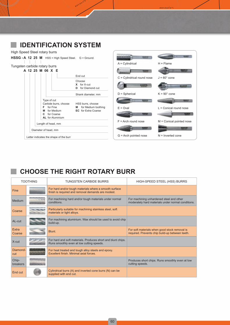
60
D = y + φ (x º / d2)D = y + φ (x º / d2) D = y + φ (x º / d2)
ø 34 H. 23 (ø 8 +Ω.1977)ø 30 H. 29 (ø 12 + Ω.1981 )
IDENTIFICATION SYSTEMHigh Speed Steel rotary burrsHSSG - HSS = High Speed Steel.25 M12A
Tungsten carbide rotary burrs25 06M X E12A
G = Ground.
A = Cylindrical
C = Cylindrical round nose
D = Spherical
E = Oval
F = Arch round nose
G = Arch pointed nose
H = Flame
J = 60° cone
K = 90° cone
L = Conical round nose
M = Conical pointed nose
N = Inverted coneLetter indicates the shape of the burr
HSS burrs, choose M for Medium toothing EC for Extra Coarse
End cut
Choose X for X-cut D for Diamond cut
Shank diameter, mm
Type of cut Carbide burrs, choose F for Fine M for MediumC for Coarse AL for Aluminium
Length of head, mm
Diameter of head, mm
TOOTHING TUNGSTEN CARBIDE BURRS HIGH-SPEED STEEL (HSS) BURRS
Fine For hard and/or tough materials where a smooth surface finish is required and removal demands are modest.
Medium For machining hard and/or tough materials under normal conditions.
For machining unhardened steel and other moderately hard materials under normal conditions.
Coarse Particularly suitable for machining stainless steel, soft materials or light alloys.
AL-cut For machining aluminium. Wax should be used to avoid chip build-up.
Extra Coarse Blunt. For soft materials when good stock removal is
required. Prevents chip build-up between teeth.
X-cut For hard and soft materials. Produces short and blunt chips. Runs smoothly even at low cutting speeds.
Diamond-cut
For heat treated and tough alloy steels and epoxy. Excellent finish. Minimal axial forces.
Chip-breakers
Produces short chips. Runs smoothly even at low cutting speeds.
End cut Cylindrical burrs (A) and inverted cone burrs (N) can be supplied with end cut.
CHOOSE THE RIGHT ROTARY BURR

16
12
10
8
6
310 20 30 40 70 100 15 25 35 50
16
12
10
8
610 20 30 40 50 60 70 80 90 100
61
D = y + φ (x º / d2) D = y + φ (x º / d2)D = y + φ (x º / d2)
ø 34 H. 23 (ø 8 +Ω.1977)ø 30 H. 29 (ø 12 +Ω.1981)
Tungsten Carbide burrs are designed for use in sturdy, well-maintained machines running at highly stable speeds above 15.000 r.p.m. They can be utilised on most materials with degrees or hardness up to about 67 HRC (Rockwell C). The cutting head of the burr is made of tungsten carbide with an approximate hardness of 1500 HV (Vickers). Close co-operation between experts has produced different carbides for different sizes to ensure best cutting performance
The cutting head on large burrs is brazed to a shank of hardened steel, tempered to 46 HRC. A unique brazing method produces exceptionally strong joints. Smaller burrs, on the other hand, are made in a single solid piece entirely of tungsten carbide. High Speed Steel burrs are primarily used for deburring soft steel, bronze, brass, etc.
RECOMMENDED OPERATING SPEEDS R.P.M.Tungsten Carbide
Head Ø mm
Hardened steels, high-strength
materials.
Unhardened steels, softer materials and
cast iron.
Soft materials, alumi-nium, thermoplastics,
brass.
R.P.M x 1000 R.P.M x 1000 R.P.M x 1000
3 40 - 80 50 - 90 50 - 100
6 25 - 60 30 - 60 30 - 70
8 20 - 45 25 - 50 25 - 50
10 17 - 40 20 - 40 20 - 40
12 15 - 30 17 - 30 17 - 35
16 12 - 25 15 - 25 15 - 30
High Speed Steel
Head Ø mm
Unhardened steels, softer materials and
cast iron.
Soft materials, alumi-nium, thermoplastics,
brass.
R.P.M x 1000 R.P.M x 1000
6 5 - 20 20 - 40
10 3 - 10 10 - 30
12 1 - 10 10 - 30
16 1 - 8 10 - 25
For machining in harder materials use lower speed and finer cut. Note that the cutting performance is highly dependable on the machine bearing condition and the characteristics of the machine (the cutting speed must not slow down when deburring).
Burr head, Ø mmBurr head, Ø mm
x 1000 r.p.m.
x 1000 r.p.m.
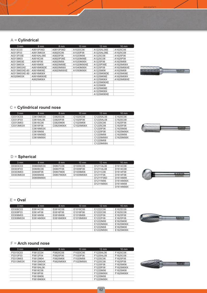
62
D = y + φ (x º / d2)D = y + φ (x º / d2) D = y + φ (x º / d2)
ø 34 H. 23 (ø 8 +Ω.1977)ø 30 H. 29 (ø 12 + Ω.1981 )
3 mm 6 mm 8 mm 10 mm 12 mm 16 mmA0313C03 A0610F06D A0810F06D A1020C06 A1225AL06E A1625C06A0313F03 A0613M03X A0820C06 A1020F06 A1225AL08E A1625C08A0313F03E A0616AL06E A0820F06 A1020M06 A1225C06 A1625F06A0313M03 A0616C06 A0820F06E A1020M06E A1225C08 A1625F08A0313M03E A0616F06 A0820M06 A1020M06X A1225F06 A1625M06A0313M03X A0616M06 A0820M06E A1020M06XE A1225F06E A1625M06XA0313M03XE A0616M06DE A0820M06X A1040M06X A1225F08 A1625M06XEA0313M03XE-60 A0616M06E A0820M06XE A1050M06X A1225M06 A1625M08A0313M03XE-80 A0616M06X A1225M06DE A1625M08EA0320M03X A0616M06XE A1225M06E A1625M08X
A0625M06X A1225M06X A1625M08XEA1225M06XEA1225M08A1225M08EA1225M08XA1225M08XE
A = Cylindrical
3 mm 6 mm 8 mm 10 mm 12 mm 16 mmC0313C03 C0613M03X C0820C06 C1020C06 C1225AL06 C1625C06C0313F03 C0616AL06 C0820F06 C1020F06 C1225AL08 C1625C08C0313M03 C0616C06 C0820M06 C1020M06 C1225C06 C1625F06C0313M03X C0616F06 C0820M06X C1020M06X C1225C08 C1625F08
C0616M03X C1225F06 C1625M06C0616M06 C1225F08 C1625M06XC0616M06D C1225M06 C1625M08C0616M06X C1225M06X C1625M08X
C1225M08C1225M08X
C = Cylindrical round nose
3 mm 6 mm 8 mm 10 mm 12 mm 16 mmD0303C03 D0605M03X D0807C06 D1009C06 D1211AL06 D1614C06D0303F03 D0606C06 D0807F06 D1009F06 D1211AL08 D1614C08D0303M03 D0606F06 D0807M06 D1009M06 D1211C06 D1614F06D0303M03X D0606M06 D0807M06X D1009M06X D1211F06 D1614F08
D0606M06X D1211F06D D1614M06D1211M06 D1614M06XD1211M06X D1614M08
D1614M08X
D = Spherical
3 mm 6 mm 8 mm 10 mm 12 mm 16 mmE0308C03 E0614C06 E0816C06 E1018C06 E1222C06 E1625C06E0308F03 E0614F06 E0816F06 E1018F06 E1222C08 E1625C08E0308M03 E0614M06 E0816M06 E1018M06 E1222F06 E1625F06E0308M03X E0614M06X E0816M06X E1018M06X E1222F08 E1625F08
E1222M06 E1625M06E1222M06X E1625M06XE1222M08 E1625M08E1222M08X E1625M08X
E = Oval
3 mm 6 mm 8 mm 10 mm 12 mm 16 mmF0313C03 F0612C04 F0820C06 F1020C06 F1225AL06 F1625C06F0313F03 F0612F04 F0820F06 F1020F06 F1225AL08 F1625C08F0313M03 F0612M04 F0820M06 F1020M06 F1225C06 F1625F06F0313M03X F0612M04X F0820M06X F1020M06X F1225C08 F1625F08
F0613M03X F1225F06 F1625M06F0618AL06 F1225F08 F1625M06XF0618C06 F1225M06 F1625M08F0618F06 F1225M06X F1625M08XF0618M06 F1225M08F0618M06X F1225M08X
F = Arch round nose

63
D = y + φ (x º / d2) D = y + φ (x º / d2)D = y + φ (x º / d2)
ø 34 H. 23 (ø 8 +Ω.1977)ø 30 H. 29 (ø 12 +Ω.1981)
3 mm 6 mm 8 mm 10 mm 12 mm 16 mmG0313C03 G0613M03X G0820C06 G1020C06 G1225C06 G1625C06G0313F03 G0618C06 G0820F06 G1020F06 G1225C08 G1625C08G0313M03 G0618F06 G0820M06 G1020M06 G1225F06 G1625F06G0313M03X G0618M06 G0820M06X G1020M06X G1225F08 G1625F08
G0618M06X G0845M6.6X G1050M8.3X G1225M06 G1625M06G0645M4.9X G1225M06X G1625M06X
G1225M08 G1625M08G1225M08X G1625M08X
G = Arch pointed nose
3 mm 6 mm 8 mm 10 mm 12 mm 16 mmH0613M03X H1025C06 H1232M06 H1635C06
H1025F06 H1232M06X H1635C08H1025M06 H1635F06H1025M06X H1635F08H1025M08 H1635M06
H1635M06XH1635M08H1635M08X
H = Flame
3 mm 6 mm 8 mm 10 mm 12 mm 16 mmJ0604C06 J1010C06 J1212M06 J1616C06J0604F06 J1010F06 J1616C08J0604M06 J1010M06 J1616F06
J1616F08J1616M06J1616M08
J = 60° cone
3 mm 6 mm 8 mm 10 mm 12 mm 16 mmK0602C06 K1008C06 K1210C06 K1612C06K0602F06 K1008F06 K1210F06 K1612C08K0602M06 K1008M06 K1210M06 K1612F06
K1612F08K1612M06K1612M08
K = 90° cone
3 mm 6 mm 8 mm 10 mm 12 mm 16 mmL1020C06 L1225F06 L1630C06L1020F06 L1225M06 L1630C08L1020M06 L1225M06X L1630F06L1020M06X L1230AL06 L1630F08
L1230AL08 L1630M06L1230C06 L1630M06XL1230F06 L1630M08L1230M06 L1630M08XL1230M06X
L = Conical round nose
3 mm 6 mm 8 mm 10 mm 12 mm 16 mmM0310C03 M0613M03X M1022C06 M1227C06 M1630C06M0310F03 M0618C06 M1022F06 M1227C08 M1630C08M0310M03 M0618F06 M1022M06 M1227F06 M1630F06M0310M03X M0618M06 M1022M06D M1227F08 M1630F08
M0618M06X M1022M06X M1227M06 M1630M06M1227M06X M1630M06XM1227M08 M1630M08M1227M08X M1630M08X
M = Conical pointed nose
3 mm 6 mm 8 mm 10 mm 12 mm 16 mmN0306C03 N0607C06 N1213C06 N1613C06N0306F03 N0607F06 N1213F06 N1613C08N0306M03 N0607M06 N1213M06 N1613F06N0306M03E N0607M06E N1213M06E N1613F08
N1613M06N1613M06EN1613M06XN1613M08
N = Inverted nose

Bahco is a registered trademark of SNA Europe Group7 314150 274079
MCC14-ENG