banner maxi-amp photoelectric amplifiers - clrwtr.com may also be connected to the logic level...
TRANSCRIPT

MODEL
CP12C
CP12RC
None105 to 130V ac(15 VA) or
210 to 250V ac(15 VA)50/60Hz
SPDT5-ampelectro-me-chanical
INPUTVOLTAGE
OUTPUT DE-VICE
OUTPUT POWER
120V ac Hookup Diagram, CP12C 120V ac Hookup Diagram, CP12RC
220/240V ac Hookup Diagram, CP12RC220/240V ac Hookup Diagram, CP12C
Printed in USA P/N 03460C3B
Banner Engineering Corp. 9714 10th Ave. N., Minneapolis, MN 55441 Telephone: (763) 544-3164 FAX (applications): (763) 544-3573
400 milliampsmaximumfor 10-30V dc sensing devices
MAXI-AMP™System CP Series Power Supply Modules
DimensionsLoad Curve
MAXI-AMP CP Series power supply modules provide a convenient source of power for 10 to 30V dc sensing devices such as Banner self-contained dc sensors and/or any of the Banner logic modules and remote amplifiers. It is an excellent way to supply power to a system using multiple MAXI-AMP modules and associated sensors.
These supplies are designed for either 120 or 220/240V ac input volt-age (see hookup diagrams). They offer 400 milliamps for powering 10 to 30V dc devices.
Model CP12RC includes a relay which may be switched by a current sinking device (pin #2) or a current sourcing device (pin #8). The relay is a single-pole double-throw (SPDT) 5 amp electromechanical type.
CP series power supplies are built into the rugged MAXI-AMP housing. They connect via a standard 11-pole round-pin relay socket (Banner RS-11). The RS-11 socket allows DIN rail mounting of the power supply. Operating temperature for CP series power supply modules is 0 to 50 degrees C (32 to 122 degrees F).
SINKING INPUT
8
7
6
5
4
910
111
2
3
CR
+V output (see load curve)
dc COMMON
RELAY OUTPUT 5 AMP CONTACTS
105 to 130V ac
CP12RCSOURCING INPUT
+12V CR
8
7
6
5
4
910
111
2
3 +V output (see load curve)
dc COMMON
RELAY OUTPUT 5 AMP CONTACTS
210 to 250V ac
CP12RC
SOURCING INPUT
SINKING INPUT
CR
+12V CR
Clearwater Tech - Phone: 800.894.0412 - Fax: 208.368.0415 - Web: www.clrwtr.com - Email: [email protected]

The Banner model OC-12 is an optical coupler module used to interface the outputs of amplifiers and amplified scan-ners to other logic systems such as computers, programmable logic controllers (PLCs), solid-state totalizers, preset counters, speed controls, and any other devices which must be isolated from ground. The OC-12 allows interfacing between systems operating at different DC voltage levels (e.g. - a 24V dc sensor to a 5V dc logic circuit).
The OC-12's output is a phototransistor capable of sinking up to 50mA dc at applied voltages of up to 30V dc. The OC-12 may NOT be used to switch AC. Response time is less than 100 microseconds, and life is infinite. On-state saturation voltage is less than 1V dc, and off-state leakage current is less than 10 microamps.
The OC-12's input is compatible with the NPN or PNP transistor outputs of all Banner amplified DC photoelectric sensors, including the MULTI-BEAM, MAXI-BEAM, VALU-BEAM, MINI-BEAM, and ECONO-BEAM families. It may also be connected to the logic level outputs of Banner MAXI-AMP CL3, CM3, and CR3 Series modules and to the outputs of Banner "M" and "B" series amplifiers and MICRO-AMP family amplifiers and logic modules.
The OC-12 has a standard octal plug base, and is wired using a standard octal relay socket (Banner model OS-8). The OC-12 may also be used in place of the electromechanical relay on the model MRB control chassis.
DIMENSION DRAWING FUNCTIONAL SCHEMATIC
SYSTEMS INTERFACE DEVICE:Optical Coupler ModuleOC-12
SpecificationsINPUT: 10-30V dc. Connects directly to the PNP or NPN transistor output of all Banner self-contained (amplified) DC photo-electric sensors (MULTI-BEAM, MAXI-BEAM, VALU-BEAM, MINI-BEAM, and ECONO-BEAM families); CM3, CL3, CR3, "M", and "B" series amplifiers; and MICRO-AMP amplifiers and logic modules.
OUTPUT: ground-isolated optically-coupled NPN current sinking phototransistor, 50mA maximum at 30V dc maximum.
RESPONSE TIME: less than 100 microseconds (0.1 milliseconds).
ON-STATE SATURATION VOLTAGE: less than 1V dc. Photodarlington output.
OFF-STATE LEAKAGE CURRENT: less than 10 microamps.
OPERATING TEMPERATURE: 0 to 50 degrees C (32 to 122 degrees F).
CONSTRUCTION: standard black plastic octal-plug relay housing.
Banner Engineering Corporation 9714 10th Ave. No., Minneapolis, Mn. 55441 Telephone: (612) 544-3164 FAX (applications): (612) 544-3573
WARRANTY: Banner Engineering Corporation warrants its products to be free of defects for one year. Banner Engineering Corporation will repair or replace, without charge, any product of its manufacture found to be defective at the time it is returned to the factory during the warranty period. This warranty does not cover damage or liability for the improper application of Banner products. This warranty is in lieu of any other warranty either expressed or implied.
Printed in USA P/N 03444H8A
Clearwater Tech - Phone: 800.894.0412 - Fax: 208.368.0415 - Web: www.clrwtr.com - Email: [email protected]

Clearwater Tech - Phone: 800.894.0412 - Fax: 208.368.0415 - Web: www.clrwtr.com - Email: [email protected]
Clearwater Tech - Phone: 800.894.0412 - Fax: 208.368.0415 - Web: www.clrwtr.com - Email: [email protected]

Clearwater Tech - Phone: 800.894.0412 - Fax: 208.368.0415 - Web: www.clrwtr.com - Email: [email protected]

Clearwater Tech - Phone: 800.894.0412 - Fax: 208.368.0415 - Web: www.clrwtr.com - Email: [email protected]

Clearwater Tech - Phone: 800.894.0412 - Fax: 208.368.0415 - Web: www.clrwtr.com - Email: [email protected]

Clearwater Tech - Phone: 800.894.0412 - Fax: 208.368.0415 - Web: www.clrwtr.com - Email: [email protected]
Clearwater Tech - Phone: 800.894.0412 - Fax: 208.368.0415 - Web: www.clrwtr.com - Email: [email protected]

Clearwater Tech - Phone: 800.894.0412 - Fax: 208.368.0415 - Web: www.clrwtr.com - Email: [email protected]
P/N 03449D4E
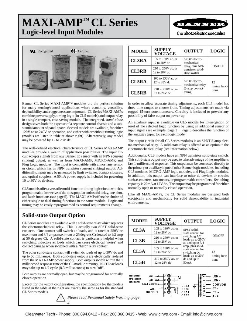
CL Series modules are available with a solid-state relay which replaces the electromechanical relay. This is actually two SPST solid-state contacts. One contact will switch ac loads, and is rated at 250V ac maximum and 3/4 amps maximum at 25 degrees C (derated to 1/2 amp at 50 degrees C). A solid-state contact is particularly helpful when switching inductive ac loads which can cause electrical "noise" and contact damage when switched with a "hard" relay contact.
The other solid-state contact will switch dc loads of up to 30V dc and up to 50 milliamps. Both solid-state outputs are electrically isolated from the MAXI-AMP power supply. Both outputs switch within the 1 millisecond response time of the CL module circuitry. NOTE: ac loads may take up to 1/2 cycle (8.3 milliseconds) to turn "off".
Both outputs are normally open, but may be programmed for normally closed operation.
Except for the output configuration, the specifications for the models listed in the table at the right are exactly the same as for the standard CL Series models.
Solid-state Output OptionMODEL OUTPUT LOGIC
ON/OFF
12timing func-tions
105 to 130V ac, or 12 to 28V dc
210 to 250V ac, or 12 to 28V dc
CL3A
CL3B
CL5A
CL5B
105 to 130V ac, or 12 to 28V dc
210 to 250V ac, or 12 to 28V dc
SUPPLYVOLTAGE
Banner CL Series MAXI-AMP™ modules are the perfect solution for many sensing/control applications where economy, versatility, dependability, and ruggedness are important. CL Series MAXI-AMPs combine power supply, timing logic (in CL5 models) and output relay in a single compact, cost-saving module. The integrated, stand-alone design saves both the expense of a separate control chassis and a sub-stantial amount of panel space. Several models are available, for either 120V ac or 240V ac operation, and either with or without timing logic (models are listed in table at above right). Alternatively, any model may be powered by 12 to 28V dc.
The well-defined electrical characteristics of CL Series MAXI-AMP modules provide a wealth of application possibilities. The input cir-cuit accepts signals from any Banner dc sensor with an NPN (current sinking) output; as well as from MAXI-AMP, MICRO-AMP, and Plug Logic modules. The input is compatible with almost any sensor or circuit which has an NPN transistor (current sinking) output. Ad-ditionally, inputs may be generated by limit switches, contact closures, and optical couplers. A 50mA power supply is included for powering 10 to 30V dc devices.
CL5 models offer a versatile multi-function timing logic circuit which is programmable for twelve of the most popular and useful delay, one-shot, and latch functions (see page 5). The MAXI-AMP offers the choice of either single or dual timing functions in the same module. Logic and timing may be easily reprogrammed as control requirements change.
In order to allow accurate timing adjustments, each CL5 model has three time ranges to choose from. Timing adjustments are made via rugged 15-turn potentiometers. Circuitry is included to prevent any possibility of false output on power-up.
An auxiliary input is available on CL5 models for interrogation or reset of the selected logic function by using an additional sensor or input signal (see example, page 3). Page 5 describes the function of the auxiliary input for each logic mode.
The output circuit for all CL Series modules is an SPDT 5-amp elec-tro-mechanical relay. A solid-state relay is offered as an option to the electromechanical relay (see information below).
Additionally, CL3 models have an NPN transistor solid-state switch. This solid-state output may be used to take advantage of the amplifier's fast 1-millisecond response. This output may be connected directly to the primary or auxiliary input of other Banner logic modules, including CL5 modules, MICRO-AMP logic modules, and Plug Logic modules. In addition, this output can interface to other dc devices or circuits such as counters, rate meters, or programmable controllers. Switching capacity is 20mA at 12V dc. The output may be programmed for either normally open or normally closed operation.
Like all MAXI-AMPs, the CL Series modules are designed both electrically and mechanically for solid dependability in industrial environments.
MODEL
CL3RA
CL3RB
CL5RA
CL5RB
SPDT electro-mechanical relay (5 amp contact rating)
ON/OFF
12timing func-tions
105 to 130V ac, or 12 to 28V dc
210 to 250V ac, or 12 to 28V dc
SUPPLYVOLTAGE
210 to 250V ac, or 12 to 28V dc
105 to 130V ac, or 12 to 28V dc
SPST solid-state contact for switching AC loads up to 250V ac and up to 3/4 amp, plus solid-state contact for switching dc loads up to 30V dc and up to 50mA.
SPDT electro-mechanical relay, plus NPN transistor solid-state switch
OUTPUT LOGICRecognized Certified
Please read Personnel Safety Warning, page 3.
MAXI-AMP™ CL Series Logic-level Input Modules
Clearwater Tech - Phone: 800.894.0412 - Fax: 208.368.0415 - Web: www.clrwtr.com - Email: [email protected]

CL3 Models
NOTE #1: power is available at pins #3 (+) and #1 (-) for an external 10 to 30V dc device (see hookup example). Current available is 50mA at 120V ac (240V ac) line level; 40mA at 105V ac (210V ac) line level. Alternately, the module may be powered by 12 to 28V dc at pins #3 (+) and #1 (-). Do not connect ac voltage if using external dc power.
NOTE #2: pulling pin #9 low (to Common) will inhibit the timing, or reset the latch of CL5 models. (See "Description of Logic Functions", page 5)NOTE #3: pin #9 of model CL3RA and CL3RB may be connected directly to the pri-mary or auxiliary input of MAXI-AMP model CL5 or to Banner Plug Logic modules.
Functional Schematics
Dimension Drawing
CL5 Models
2
Generalized Hookup: models with electromechanical relay output
INDICATOR LEDs: Red indicator LEDs for input and output status.
CONSTRUCTION: Rugged NORYL® polyphenylene oxide (PPO®) housing, 1.6" x 2.3" x 4". Standard round-pin 11-pole plug base.
OPERATING TEMPERATURE: 0 to 50 degrees C (32 to 122 degrees F).
SUPPLY VOLTAGE: Models CL3RA, CL5RA: 105 to 130V ac, 50/60Hz (4 VA), or 12 to 28V dc* at 60mA. Models CL3RB, CL5RB: 210 to 250V ac, 50/60Hz (4 VA), or 12 to 28V dc at 60mA. *Do not connect ac voltage if using external dc power.
OUTPUT CONFIGURATION: all models have SPDT electro-mechanical relay:CONTACT RATING: 250V ac max, 24V dc max, 5 amps max. (resis-tive load), 1/10 H.P. at 240V ac. Install transient suppressor (MOV) across contacts which switch inductive loads.CLOSURE TIME: 10 milliseconds max.RELEASE TIME: 10 milliseconds max.MAXIMUM SWITCHING SPEED: 20 operations/secondMECHANICAL LIFE: 20,000,000 operationsCL3 models also have a logic level current sinking NPN transistor switch at pin #9. See schematic below and hookup info.
AMPLIFIER: RESPONSE SPEED: 1 millisecondINPUT CHARACTERISTICS: input is switched when the voltage at pin #2 is pulled below 1V dc or when less than 1K ohms is connected between pins #2 and #1. When an inverting jumper is connected be-tween pins #10 and #11, input is switched when the voltage at pin #2 rises above 4.5V dc or when the impedance between pins #2 and #1 exceeds 15K ohms.HYSTERESIS: greater than .35 volts, less than 2 volts.
MULTIPLE SENSOR HOOKUP: any number of switched output devices may be connected in parallel to the input (see hookup ex-ample).
TIMERS (CL5 models only):TIME RANGES: LOW range - 10 to 150 milliseconds MIDDLE range - 0.1 to 1.5 seconds HIGH range - 1 to 15 secondsREPEATABILITY: +/-2% of set time over all extremes of supply voltage and temperature
ADJUSTMENTS: Miniature switches for setting of timing func-tion, timing range, and output polarity (CL5 models). 15-turn clutched potentiometer for time setting (CL5 models).
MAXI-AMP CL Series Specifications
Clearwater Tech - Phone: 800.894.0412 - Fax: 208.368.0415 - Web: www.clrwtr.com - Email: [email protected]

PBT
1 2
3 4
MULTI-BEAM
CL3 or CL5model8
7
6
5
4
910
111
23
CL3 or CL5model8
7
6
54
910
111
23
MAXI-BEAM
4321
RPBT
Sensor Hookup Diagrams, CL Series MAXI-AMP Modules
To MAXI-BEAM Sensors To MULTI-BEAM Sensors
NOTE: the MAXI-AMP cannot power a MULTI-BEAM emitter and receiver pair.Use a separate power source for the emitter (e.g.- power block PBA-1, etc.)
NOTE: use power block model RPBT.
NOTE: use power block model PBT or PBT2.
To MINI-BEAM SM312 Series Sensors To VALU-BEAM SM912 Series Sensors SM912
WHITE
BROWN
BLUE
NOTE: Black wire is not used
CL3 or CL5model8
7
6
5
4
910
111
23
To EZ-BEAM SensorsNOTE: Black wire is not used SE612
WHITE
BROWN
BLUE
CL3 or CL5model8
7
6
5
4
910
111
23
BROWN
BLUE
BLACK CL3 or CL5model8
7
6
5
4
9
10
11
123
To ECONO-BEAM SE612 Series Sensors NOTE: White wire is not used
This hookup is for DC NPN (current sinking) models of S18 Series, Q25 Series, and other DC sensors bearing the EZ-BEAM logo.
CL5 model MAXI-AMPs have an auxiliary input at terminal #9 which may be used for the interrogation or reset of the selected logic function. This is accomplished by a switch closure between pins #9 and #1 (Common). The auxiliary input may also be switched by a DC device with an NPN transistor (current sinking) output. The effect of the auxiliary input is described for each logic function on page 5.
This example shows a typical inspection/rejection scheme which uses a Banner MINI-BEAM as the inspection sensor. Typically, the CL5 module would be programmed for the ONE-SHOT or DELAYED ONE-SHOT logic function. If the SM312 "sees" an acceptable condition when the SE612 senses the leading (or trailing) edge of the product, the SM312 will inhibit a reject pulse from occuring. Reject products will be ejected by the output pulse.
NOTE: the MAXI-AMP can supply 50mA for external 10 to 30V dc devices. Carefully check the current draw of the devices to be powered by the MAXI-AMP.
Use of Auxiliary Input (CL5 models)
WARNING The MAXI-AMP modules described in this data sheet do NOT include the self-checking redundant circuitry neces-sary to allow their use in personnel safety applications. A failure or malfunction can result in either an energized or a de-energized output condition.
Never use these products for personnel protection. Their use as safety devices may create an unsafe condition which could lead to seri-ous injury or death.
Only MACHINE-GUARD and PERIMETER-GUARD Systems, and other systems so designated, are designed to meet OSHA and ANSI machine safety standards for point-of-operation guarding devices. No other Banner sensors or controls are designed to meet these standards, and they must NOT be used as sensing devices for personnel protection.
NOTE: Black wire is not used
SM312
BROWN
BLUE
WHITE CL3 or CL5model8
7
6
54
910
111
23
NOTE: black wire is not used.
Clearwater Tech - Phone: 800.894.0412 - Fax: 208.368.0415 - Web: www.clrwtr.com - Email: [email protected]

(NOTE: see page 5 for description of logic functions)
The diagram shows switch locations, and the table summarizes the program switch positions.
A group of ten switches located on one side of the module is used to select the timing logic for CL5 models.
Switches #1 through #7 are used to select the logic function. Switch #8 programs the output for either NORMALLY OPEN or NORMALLY CLOSED operation. Switches #9 and #10 program the time range(s). There are three ranges: 10 to 150 milliseconds, 0.1 to 1.5 seconds, and 1 to 15 seconds. The programmed range will be the same for both functions of a dual timing mode (ON & OFF DELAY, DELAYED ONE-SHOT, and REPEAT CYCLE). However, DELAY and HOLD times are independently adjustable within the selected range.
4
LIGHT OPERATE
DARK OPERATE
DARK OPERATE
If any receiver "sees"light
When all receivers "see" dark
OUTPUT OCCURS (AFTER DELAY, IF ANY)
If any receiver "sees"dark
When all receivers "see" light
NO
NO
YES
YES
LIGHT OPERATE
INVERTING JUMPERInstalled Between Module Terminals #10 and #11
SENSOR PROGRAM:Light or Dark Operate LOGIC DESCRIPTION
Hookup of Multiple Self-contained SensorsAny number of self-contained dc sensors may be wired together in parallel to a single CL Series MAXI-AMP module to create almost any multiple-sensor logic configuration. Power for the sensors may be obtained from MAXI-AMP 400mA power supply CP12 (shown below) or from 1-amp model PS120-15. The table at the right describes how the four most frequently used multiple-sensor logic configurations may be created.
MINI-BEAM SM312 Series and VALU-BEAM SM912 Series sensors have a switch on the back of their housings which is used to program the sensors for LIGHT or DARK operate. MAXI-BEAM sensors are set for LIGHT or DARK operate using the programming ring. MULTI-BEAM sensors are programmed for LIGHT or DARK operate with the logic module jumper wire. OMNI-BEAMs are programmed by a switch in the sensor block.
For ON/OFF sensor operation, light operate is equated to normally open output, and dark operate is defined as normally closed. EZ-BEAM sensors have both a normally open and a normally closed output. Selection of either output determines the LIGHT/DARK operate mode. ECONO-BEAM sen-sors are not programmable and must be ordered for LIGHT OPERATE (standard models) or DARK OPERATE (model suffix "NC").
The addition of a jumper wire between MAXI-AMP terminals #10 and #11 changes the input response from a low-going to a high-going signal. This feature, combined with the selection of LIGHT or DARK operate at the sensor, allows "AND" logic with parallel sensor connections.
LIGHT "OR"
DARK "AND"
DARK "OR"
LIGHT "AND"
Timing Logic Programming (CL5 models)Settings illustrated below are factory settings. Factory settings are "underlined" in the table.
MAXI-AMP CL Series
Brown+V dc
Brown+V dc
Blue(#1)
White
+V dc
Brown
105-130V AC
Blue(#1)
SM31R/RL
White
SM31R/RL SM31E/EL Blue(#1)
Brown+V dc
Blue SM31R/RL
White
CL3 or CL5model8
7
6
5
4
910
111
23
CP12power supply
87
6
5
4
910
111
23
SM31E/EL Blue(#1)
Brown+V dc
SM31E/EL Blue(#1)
Brown+V dc105-130V ac
Clearwater Tech - Phone: 800.894.0412 - Fax: 208.368.0415 - Web: www.clrwtr.com - Email: [email protected]

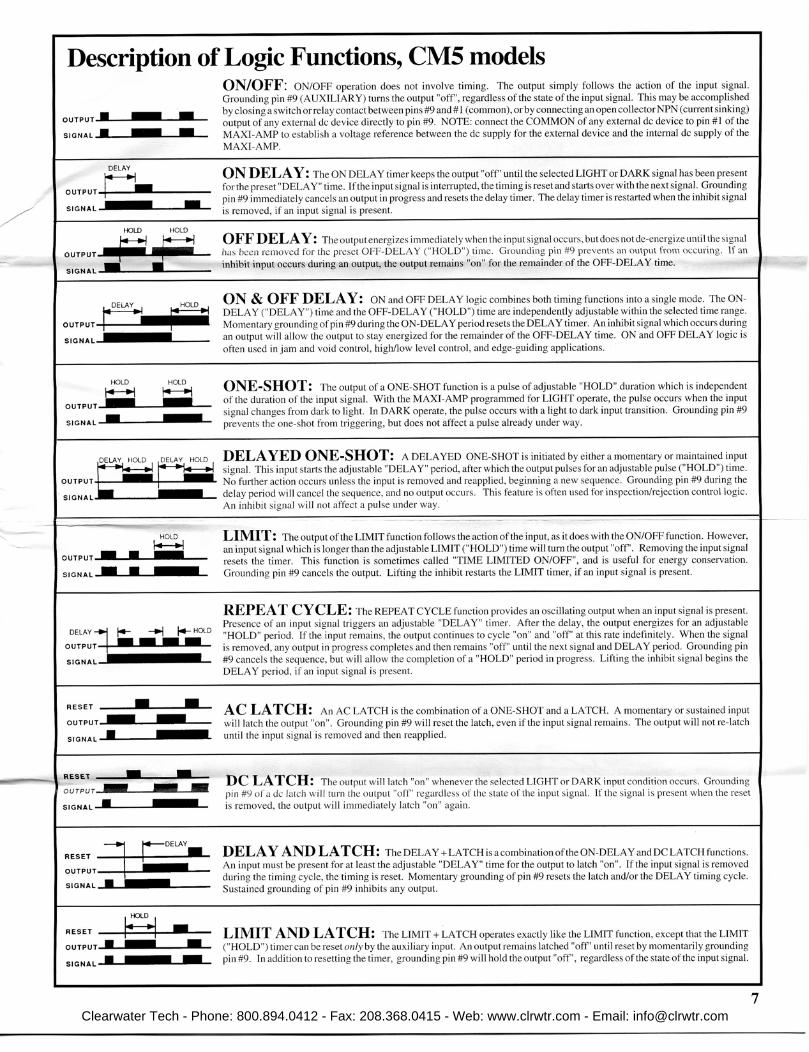
LIMIT: The output of the LIMIT function follows the action of the input, as it does with the ON/OFF function. However, an input signal which is longer than the adjustable LIMIT ("HOLD") time will turn the output "off". Removing the input signal resets the timer. This function is sometimes called "TIME LIMITED ON/OFF", and is useful for energy conservation. Grounding pin #9 cancels the output. Lifting the inhibit restarts the LIMIT timer, if an input signal is present.
ON/OFF: ON/OFF operation does not involve timing. The output simply follows the action of the input signal. Grounding pin #9 (AUXILIARY) turns the output "off", regardless of the state of the input signal. This may be accomplished by closing a switch or relay contact between pins #9 and #1 (common), or by connecting an open collector NPN (current sinking) output of any external dc device directly to pin #9. NOTE: connect the COMMON of any external dc device to pin #1 of the MAXI-AMP to establish a voltage reference between the dc supply for the external device and the internal dc supply of the MAXI-AMP.
ON DELAY: The ON DELAY timer keeps the output "off" until the selected LIGHT or DARK signal has been pres-ent for the preset "DELAY" time. If the input signal is interrupted, the timing is reset and starts over with the next signal. Grounding pin #9 immediately cancels an output in progress and resets the delay timer. The delay timer is restarted when the inhibit signal is removed, if an input signal is present.
OFF DELAY: The output energizes immediately when the input signal occurs, but does not de-energize until the signal has been removed for the preset OFF-DELAY ("HOLD") time. Grounding pin #9 prevents an output from occuring. If an inhibit input occurs during an output, the output remains "on" for the remainder of the OFF-DELAY time.
ON & OFF DELAY: ON and OFF DELAY logic combines both timing functions into a single mode. The ON-DELAY ("DELAY") time and the OFF-DELAY ("HOLD") time are independently adjustable within the selected time range. Momentary grounding of pin #9 during the ON-DELAY period resets the DELAY timer. An inhibit signal which occurs during an output will allow the output to stay energized for the remainder of the OFF-DELAY time. ON and OFF DELAY logic is often used in jam and void control, high/low level control, and edge-guiding applications.
ONE-SHOT: The output of a ONE-SHOT function is a pulse of adjustable "HOLD" duration which is independent of the duration of the input signal. With the MAXI-AMP programmed for LIGHT operate, the pulse occurs when the input signal changes from dark to light. In DARK operate, the pulse occurs with a light to dark input transition. Grounding pin #9 prevents the one-shot from triggering, but does not affect a pulse already under way.
DELAYED ONE-SHOT: A DELAYED ONE-SHOT is initiated by either a momentary or maintained input signal. This input starts the adjustable "DELAY" period, after which the output pulses for an adjustable pulse ("HOLD") time. No further action occurs unless the input is removed and reapplied, beginning a new sequence. Grounding pin #9 during the delay period will cancel the sequence, and no output occurs. This feature is often used for inspection/rejection control logic. An inhibit signal will not affect a pulse under way.
REPEAT CYCLE: The REPEAT CYCLE function provides an oscillating output when an input signal is present. Presence of an input signal triggers an adjustable "DELAY" timer. After the delay, the output energizes for an adjustable "HOLD" period. If the input remains, the output continues to cycle "on" and "off" at this rate indefinitely. When the signal is removed, any output in progress completes and then remains "off" until the next signal and DELAY period. Grounding pin #9 cancels the sequence, but will allow the completion of a "HOLD" period in progress. Lifting the inhibit signal begins the DELAY period, if an input signal is present.
AC LATCH: An AC LATCH is the combination of a ONE-SHOT and a LATCH. A momentary or sustained input will latch the output "on". Grounding pin #9 will reset the latch, even if the input signal remains. The output will not re-latch until the input signal is removed and then reapplied.
DC LATCH: The output will latch "on" whenever the selected LIGHT or DARK input condition occurs. Grounding pin #9 of a dc latch will turn the output "off" regardless of the state of the input signal. If the signal is present when the reset is removed, the output will immediately latch "on" again.
DELAY AND LATCH: The DELAY + LATCH is a combination of the ON-DELAY and DC LATCH functions. An input must be present for at least the adjustable "DELAY" time for the output to latch "on". If the input signal is removed during the timing cycle, the timing is reset. Momentary grounding of pin #9 resets the latch and/or the DELAY timing cycle. Sustained grounding of pin #9 inhibits any output.
LIMIT AND LATCH: The LIMIT + LATCH operates exactly like the LIMIT function, except that the LIMIT ("HOLD") timer can be reset only by the auxiliary input. An output remains latched "off" until reset by momentarily ground-ing pin #9. In addition to resetting the timer, grounding pin #9 will hold the output "off", regardless of the state of the input signal.
Description of Logic Functions, CL5 models
Clearwater Tech - Phone: 800.894.0412 - Fax: 208.368.0415 - Web: www.clrwtr.com - Email: [email protected]

MAXI-AMP System Mounting and Accessories
After the panel cutout has been completed and de-burred, slide the MAXI-AMP through the cutout and place one clip assembly into the rectangular depression on each of the two narrow sides of the housing. Orient clips as shown, and alternately tighten the screws for equal pressure against the inside of the panel wall. Do not overtighten the screws. Attach the optional EC11-6 extension cable (described below) to the MAXI-AMP and route the opposite end of the cable to the RS-11 (or equivalent) socket.
Model EC11-6 extension cable is 6 feet (2m) long. Clips for panel wall mounting of the MAXI-AMP are included with the cable.
Banner Engineering Corp. 9714 Tenth Ave. No. Minneapolis, MN 55441 Telephone: (763) 544-3164 FAX (applications): (763) 544-3573
Model RS-11 Socket
The RS-11 is supplied with a coding ring and pin (see diagram at right). This allows a MAXI-AMP to be keyed to fit only its own 11-pin socket. The pin is installed in one of the eleven slots in the RS-11, and the notch in the ring is aligned to slip over the pin. When the MAXI-AMP is removed from the RS-11, the coding ring stays with the MAXI-AMP base, while the coding pin remains in the socket.
Model RS-11 is an eleven-pole round-pin screw terminal relay socket which is used to make electri-cal connections to any MAXI-AMP module. The socket provides in-line wire clamp screw terminals which will accept from one #24 AWG up to two #14 wires at each pin. The RS-11 is UL recognized (file #E92191) and CSA approved (file #LR38486). It may be mounted directly to a panel plate or via standard 35mm DIN-rail track (see below). A hold-down wire is supplied with each RS-11 socket (see dimension diagram on page 2).
Accessories for MAXI-AMP Modules
35mm DIN Rail Track Model BENC-4 EnclosureModel BENC-4 is a NEMA-4 rated corrosion-resistant enclosure for a MAXI-AMP module or other control device. It is supplied with a DIN-35-70 track for easy mounting of one RS-11 socket. For mounting two sockets, use DIN-35-105.
WARRANTY: Banner Engineering Corporation warrants its products to be free from defects for one year. Banner Engineering Corporation will repair or replace, free of charge, any product of its manufacture found to be defective at the time it is returned to the factory during the warranty period. This warranty does not cover damage or liability for the improper application of Banner products. This warranty is in lieu of any other warranty either expressed or implied.
Panel Wall Mounting of MAXI-AMP Module
Track model DIN-35-70 accomodates one RS-11 socket. Model DIN-35-105 holds two sockets. Model DIN-35-140 holds up to three sockets. The RS-11 socket is designed to snap (or slide) directly into the 35mm DIN track.
Clearwater Tech - Phone: 800.894.0412 - Fax: 208.368.0415 - Web: www.clrwtr.com - Email: [email protected]

MODEL OUTPUT LOGIC
CR3A
CR3B
CR5A
CR5B
105 to 130V ac, or 12 to 28V dc
210 to 250V ac, or 12 to 28V dc
12timing func-tions210 to 250V ac, or
12 to 28V dc
105 to 130V ac, or 12 to 28V dc
SPST solid-state contact for switching AC loads up to 250 V ac and up to 3/4 amp, plus solid-state con-tact for switch-ing DC loads up to 30V dc and up to 50mA.
SUPPLYVOLTAGE
ON/OFF
• Modulatedphotoelectricamplifier,powersupply, outputrelay,andversatiletiminglogic(CR5 models)inonecompact,stand-alonepackage
• 120or240Vacor12to28Vdcoperation;re-quires onlytheadditionofBanner"100Series"modulated remotesensor(s)tocreateacompletesensing system
• CR5modelsareeasilyprogrammedforanyof12 delay,one-shot,andlatchfunctions(singleordual timing);interrogationschemesarepossibleusing themodule'sauxiliaryinput
Printed in USA P/N 03452C4D
Model CR5RA shownwith SP100C sensor
MAXI-AMP™ CRSeries
ModulatedAmplifierModulesfor"100Series"Sensors
CR Series MAXI-AMPs combine power supply, modulated photo- electric amplifier, timing logic (in CR5 models) and output relay in a single compact, cost-saving module. The integrated stand-alone design saves both the expense of a separate control chassis and a substantial amount of panel space. Several models are available, for either 120V or 240V ac operation, and either with or without timing logic. Alte-natively, any model may be powered by 12 to 28V dc.
CR Series modules are specifically designed for use with the popular "100 Series" of Banner miniature sensors (page 3). Their rugged en-capsulated design, slim ribbon-style connecting cables, and small size make these sensors ideal for use in many situations previously considered impractical or impossible. MAXI-AMP modules themselves are also ruggedly built for dependable industrial duty.
CR Series MAXI-AMP modules contain the state-of-the-art Banner custom-designed CMOS modulator/demodulator/amplifier circuit, of-
fering high immunity to both ambient light and electrical interference plus reliable sensor performance. All models have Banner's exclusive, patented Alignment Indicating Device (AID™) system, which lights an LED indicator whenever the sensor sees a "light" condition, and pulses the LED at a rate proportional to the received light signal strength.
All CR Series modules are programmable for LIGHT or DARK operate and either high or low hysteresis. Input response time may be set at 0.3, 2, or 10 milliseconds. The 10-millisecond response mode offers enhanced immunity to electrical interference ("noise"), and also mini-mizes optical "crosstalk" between adjacent sensors.
CR5 models include a versatile multi-function timing logic circuit which is programmable for 12 of the most popular and useful delay, one-shot, and latch functions. Each timing function has a choice of three time ranges. Timing and sensitivity adjustments are accomplished via rugged 15-turn potentiometers for very accurate settings. CR Series circuitry is designed to prevent false outputs on system power-up.
The output circuit for all CR Series modules is an SPDT 5-amp electro-mechanical relay. Additionally, CR3 models have an NPN transistor solid-state switch. The output may be programmed for either normally open or normally closed operation. A solid-state relay is offered as an option to the electromechanical relay (see below).
An auxiliary input is available on CR5 models for interrogation or reset of the selected logic function (see example, page 4). Page 6 describes the function of the auxiliary input for each logic mode. A dc power supply is included for powering an additional self-contained dc sen-sor.
MODEL OUTPUT LOGIC
SPDT electro-mechanical relay (5 amp contact rating)
ON/OFF
12timing func-tions210 to 250V ac, or
12 to 28V dc
105 to 130V ac, or 12 to 28V dc
CR3RA
CR3RB
CR5RA
CR5RB
105 to 130V ac, or 12 to 28V dc
210 to 250V ac, or 12 to 28V dc
SPDT electro-mechanical relay, plus NPN transistor solid-state DC switch
SUPPLYVOLTAGE
Read Personnel Safety Use WARNING, page 7.
CR Series modules are available with a solid-state relay which replaces the electromechanical relay. This is actually two SPST solid-state contacts. One contact will switch ac loads, and is rated at 250V ac maximum and 3/4 amps maximum at 25 degrees C (derated to 1/2 amp at 50 degrees C). The other solid-state contact will switch dc loads of up to 30V dc and up to 50 milliamps. Both contacts are isolated from the MAXI-AMP power supply.
Solid-stateOutputOption
Clearwater Tech - Phone: 800.894.0412 - Fax: 208.368.0415 - Web: www.clrwtr.com - Email: [email protected]

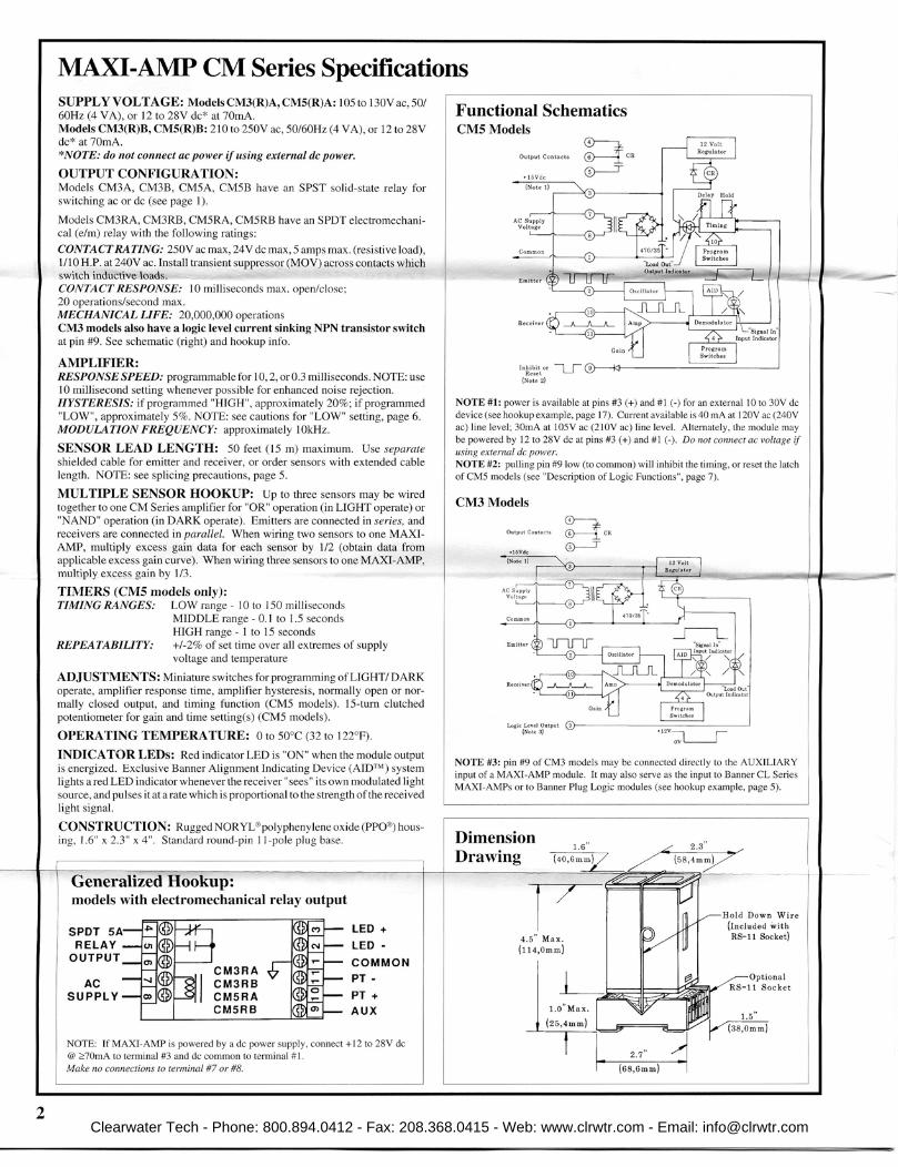
SUPPLY VOLTAGE: ModelsCR3(R)A,andCR5(R)A: 105 to 130V ac, 50/60Hz (4 VA), or 12 to 28V dc* at 70mA. ModelsCR3(R)B,andCR5(R)B: 210 to 250V ac, 50/60Hz (4 VA), or 12 to 28V dc* at 70mA.*NOTE:donotconnectacpowerifusingexternaldcpower.OUTPUT CONFIGURATION: Models CR3A, CR3B, CR5A, CR5B have an SPST solid-state relay for switch-ing ac or dc (see page 1).
Models CR3RA, CR3RB, CR5RA, CR5RB have an SPDT electromechanical (e/m) relay with the following ratings:CONTACT RATING: 250V ac max, 24V dc max, 5 amps max. (resistive load), 1/10 H.P. at 240V ac. Install transient suppressor (MOV) across contacts which switch inductive loads.CONTACT RESPONSE: 10 milliseconds max. open/close;20 operations/second max.MECHANICAL LIFE: 20,000,000 operationsCR3modelsalsohavealogiclevelcurrentsinkingNPNtransistor switchat pin #9. See schematic (right) and hookup info. AMPLIFIER: RESPONSE SPEED: programmable for 10, 2, or 0.3 milliseconds. NOTE: use 10 millisecond setting whenever possible for enhanced noise rejection. HYSTERESIS: if programmed "HIGH", approximately 20%; if programmed "LOW", approximately 5%. NOTE: see cautions for "LOW" setting (see page 5). MODULATION FREQUENCY: approximately 10kHz.
SENSOR LEAD LENGTH: 50 feet (15 m) maximum. Use separate shielded cable for emitter and receiver, or order sensors with extended cable length. NOTE: see splicing precautions.
MULTIPLE SENSOR HOOKUP: Up to three sensors may be wired together to one CR Series amplifier for "OR" operation (in LIGHT operate) or "NAND" operation (in DARK operate). Emitters are connected in series, and receivers are connected in parallel. When wiring two sensors to one MAXI-AMP, multiply excess gain data for each sensor by 1/2 (obtain data from ap-plicable excess gain curve). When wiring three sensors to one MAXI-AMP, multiply excess gain by 1/3.
TIMERS(CR5modelsonly):TIMING RANGES: LOW range - 10 to 150 milliseconds MIDDLE range - 0.1 to 1.5 seconds HIGH range - 1 to 15 secondsREPEATABILITY: +/-2% of set time over all extremes of supply voltage and temperature
ADJUSTMENTS: Miniature switches for programming of LIGHT/ DARK operate, amplifier response time, amplifier hysteresis, normally open or normally closed output, and timing function (CR5 models). 15-turn clutched potentiometer for gain and time setting(s) (CR5 models). OPERATING TEMPERATURE: 0 to 50°C (32 to 122°F).
INDICATORLEDs: Red indicator LED is "ON" when the module output is energized. Exclusive Banner Alignment Indicating Device (AID™) system lights a red LED indicator whenever the receiver "sees" its own modulated light source, and pulses it at a rate which is proportional to the strength of the received light signal.
CONSTRUCTION: Rugged NORYL® polyphenylene oxide (PPO®) hous-ing, 1.6" x 2.3" x 4". Standard round-pin 11-pole plug base.
DimensionDrawing
NOTE #1: power is available at pins #3 (+) and #1 (-) for an external 10 to 30V dc device (see hookup example, page 4). Current available is 40 mA at 120V ac (240V ac) line level; 30mA at 105V ac (210V ac) line level. Alternately, the module may be powered by 12 to 28V dc at pins #3 (+) and #1 (-). Do not connect ac voltage if using external dc power.NOTE #2: pulling pin #9 low (to common) will inhibit the timing, or reset the latch of CR5 model (see "Description of Logic Functions", page 6).
MAXI-AMPCRSeriesSpecifications
NOTE: If MAXI-AMP is powered by a dc power supply, connect +12 to 28V dc @ ≥70mA to terminal #3 and dc common to terminal #1. Make no connections to terminal #7 or #8.
CR3RACR3RBCR5RACR5RB
CR5ModelsFunctionalSchematics
NOTE #3: pin #9 of CR3 model may be connected directly to the AUXILIARY input of a MAXI-AMP or Banner M Series module. It may also serve as the input to Banner CL series MAXI-AMPs or to Banner Plug Logic modules.
CR3Models
2
GeneralizedHookup
Clearwater Tech - Phone: 800.894.0412 - Fax: 208.368.0415 - Web: www.clrwtr.com - Email: [email protected]

SensorsforusewithCRSeriesModulatedAmplifierModulesTemperature range for all miniature modulated remote sensors is 0 to 70 degrees C (+32 to 158 degrees F).Sensors are epoxy-encapsulated and optics are hermetically sealed.
SP100E & SP100RRange: 8 inches (20cm)Beam: infrared, 880nmEffectivebeam: .05 inch (1,3mm diameter)
Cable (all 6-foot lengths): SP100E: 2-wire ribbon cable (white, green).
SP100R: 3-wire ribbon cable (red, black, yellow).
SP100D, DB, C, CCF: 5-wire ribbon cable (white, green, red, black, yellow). See hookup drawing, page 4.
SP100DModels SP100D and SP100DB are general-purpose miniature diffuse sensors which detect the reflection of their own light from the surface of an object. The SP100D is a right-angle design which is generally held in place using a #4 (3mm) screw. The SP100DB ("B" = Barrel) is an in-line threaded barrel which typically mounts through a 3/8" (10mm) diameter hole using the lock nuts which are sup-plied. The optical response of these two sensors is the same.
CONVERGENTModeSensorsModels SP100C and CCF are ideally suited to applications where depth of field is critical. The emitter and receiver are both directed at a point 0.1 inch (2,5mm) ahead of the front surface. An aperture is included which, when attached, nar-rows the depth of field (see curves, below). This is particularly useful when it is necessary to detect an object while ignoring another object or a surface just a fraction of an inch farther away. The high excess gain at the focus allows detec-tion of objects of low reflectivity. The SP100C and CCF differ only in housing style. Model SP100C is for general application. Model SP100CCF is used where a narrow profile is important for mounting.
Models/Dimensions ExcessGain
SP100E and SP100R miniature opposed sensors have a slim right-angle design which allows them to be mounted in very tight locations. The thin, flexible rib-bon cable which exits from one corner may be run in any direction away from the sensing point. The SP100E and R have a wide beam angle for forgiving line-of-sight alignment. Alignment is easily made exact (and monitored) using the AID™ LED on the CR module.
OPPOSEDModeSensors
DIFFUSEModeSensorsSP100DB
SP100C SP100CCF
3
Beam Pattern
Clearwater Tech - Phone: 800.894.0412 - Fax: 208.368.0415 - Web: www.clrwtr.com - Email: [email protected]

PowerforexternaldevicesLogiclevelNPNoutput,CR3modelsThe AUXILIARY terminal (#9) of models CR3(R)A and CR3(R)B offers a logic-level NPN (current sinking) output which may be used as a fast-response solid-state inhibit signal to the AUXILIARY input of MAXI-AMP CR5 Series modules. This output may also serve as an input to any B Series or Plug Logic module. In addition, this output may interface to other dc devices or circuits like counters, rate meters, or programmable logic controllers. Switching capacity is 20mA at 12V dc.
The example here shows the use of an SP100C sensor and a CR3 module to provide inspection information, with the SP100E/R pair functioning as a product sensor. Typically, the CR5 module would be programmed for the ONE-SHOT or DELAYED ONE-SHOT logic function. If the SP100C "sees" an acceptable condition when the SP100E/R pair senses the leading (or trailing) edge of a product, the CR3 will inhibit a reject pulse from occuring.
NOTE: YELLOW is the shield (drain) wire. NOTE: YELLOW is the shield (drain) wire.
HookuptosensorpairSP100E/SP100R
HookuptosensormodelsSP100C,SP100CCF,SP100D,SP100DB
SensorHookupDiagramsforCRSeriesMAXI-AMPModules
4
External 10 to 30V dc devices such as self-contained sensors may be con-nected between terminals #3 (+) and #1 (-) of any CR Series MAXI-AMP module. Terminal #3 offers 40mA maximum. This is sufficient to power most Banner self-contained dc sensors.
In the example below, the current sinking output of a self-contained sensor powered by the MAXI-AMP may be used as the input to the AUXILIARY terminal of a CR5 module.
The example shows the use of an SE612 ECONO-BEAM sensor to provide inspection information, with the SP100E/R pair functioning as a product sen-sor. Typically, the CR5 module would be programmed for the ONE-SHOT or DELAYED ONE-SHOT logic function. If the SE612 "sees" an acceptable condition when the SP100E/R pair senses the leading (or trailing) edge of a product, it will inhibit a reject pulse from occuring.
HookuptomultiplesensorsUp to three miniature remote sensors may be connected to any CR Series MAXI-AMP. The emitter wires connect together in series to terminals #2 and #3. The receiver wires connect in parallel to terminals #10 and #11. The yellow shield wires connect together at terminal #1.
If the MAXI-AMP is programmed for LIGHT operate, the amplifier will initiate an output or the timing logic if any receiver "sees" light. In the DARK operate mode, the amplifier will output when all receivers "see" dark coincidently.
When multiple remote sensors share a common amplifier, the range of each sensor decreases. When wiring two sensors to one MAXI-AMP, multiply excess gain data for each sensor by 1/2 (obtain the data from the applicable excess gain curve). When wiring three sensors to one MAXI-AMP, multiply excess gain by 1/3.
Clearwater Tech - Phone: 800.894.0412 - Fax: 208.368.0415 - Web: www.clrwtr.com - Email: [email protected]

A group of ten switches, located on the side of the module opposite the amplifier program switches, is used to select the timing logic for the CR5 models.
Switches #1 through #7 are used to select the logic function. Switch #8 programs the output for either NORMALLY OPEN or NORMALLY CLOSED operation. Switches #9 and #10 program the time range(s). There are three ranges: 10 to 150 milliseconds, 0.1 to 1.5 seconds, and 1 to 15 seconds. The programmed range will be the same for both func-tions of a dual timing mode (ON & OFF DELAY, DELAYED ONE-SHOT, and REPEAT CYCLE). However, DELAY and HOLD times are independently adjustable within the selected range.
Amplifier response conditions may be programmed via the group of four switches located on one of the narrow sides of the MAXI-AMP module.
Switch #1 selects the amount of amplifier hysteresis. Hysteresis is the amount of signal change beyond the switching threshold which is required to cause the amplifier output to change state, and is expressed as a percent of amplifier gain. The NORMAL setting of 20% should always be used, except for low contrast situations such as many color registration applications.
NOTE: the LOW hysteresis setting should be used only when all sensing conditions remain stable. "Buzzing" of the output (in ON/OFF and LIMIT operation) or false outputs (in DELAY, ONE-SHOT, or LATCH operation) may occur if sensing variables (e.g.- web flutter) result in optical contrast approaching unity.
Switches #2 and #3 are used to program the amplifier response time. The 10 millisecond setting should be used whenever possible for the greatest immunity to electrical interference ("noise"). The 2 millisecond setting has more interference rejection than the 0.3 millisecond mode. Sensor performance (excess gain) is identical in all three response settings.
5
The diagram shows switch locations, and the table summarizes the program switch positions.
The diagram at the left shows the location of switches 1-4, and the table summarizes the settings required for each response condition.
NOTE: an adhesive-backed mylar label is supplied, which may be marked to indicate switch programming and then applied to the MAXI-AMP housing as a switch cover.
Factory settings shown at left. "Underlined" settings in table below are factory settings.
Settings illustrated below are factory settings. Factory settings are "underlined" in the table.
TimingLogicProgramming(CR5models)
AmplifierProgramming(allmodels)
Switch#4is used to select LIGHT OPERATE or DARK OPER-ATE. In the LIGHT OPERATE mode, the output will energize (in ON/OFF or LATCH operation) or the timing function will initiate (in DELAY, ONE-SHOT, or LIMIT operation) when the receiver "sees" sufficient light (excess gain greater than 1X). In DARK OPERATE, the output will energize or timing will begin when the receiver is sufficiently dark (excess gain less than 1X).
Clearwater Tech - Phone: 800.894.0412 - Fax: 208.368.0415 - Web: www.clrwtr.com - Email: [email protected]
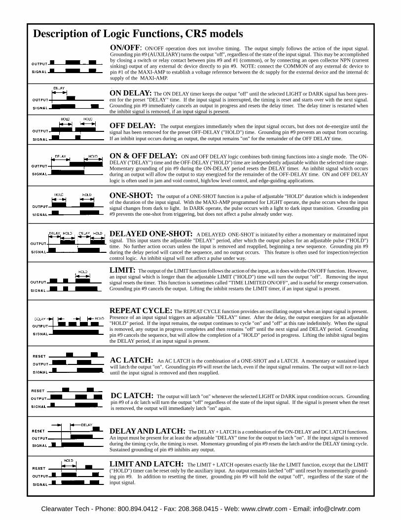
LIMIT: The output of the LIMIT function follows the action of the input, as it does with the ON/OFF function. However, an input signal which is longer than the adjustable LIMIT ("HOLD") time will turn the output "off". Removing the input signal resets the timer. This function is sometimes called "TIME LIMITED ON/OFF", and is useful for energy conservation. Grounding pin #9 cancels the output. Lifting the inhibit restarts the LIMIT timer, if an input signal is present.
ON/OFF: ON/OFF operation does not involve timing. The output simply follows the action of the input signal. Grounding pin #9 (AUXILIARY) turns the output "off", regardless of the state of the input signal. This may be accomplished by closing a switch or relay contact between pins #9 and #1 (common), or by connecting an open collector NPN (current sinking) output of any external dc device directly to pin #9. NOTE: connect the COMMON of any external dc device to pin #1 of the MAXI-AMP to establish a voltage reference between the dc supply for the external device and the internal dc supply of the MAXI-AMP.
ON DELAY: The ON DELAY timer keeps the output "off" until the selected LIGHT or DARK signal has been pres-ent for the preset "DELAY" time. If the input signal is interrupted, the timing is reset and starts over with the next signal. Grounding pin #9 immediately cancels an output in progress and resets the delay timer. The delay timer is restarted when the inhibit signal is removed, if an input signal is present.
OFF DELAY: The output energizes immediately when the input signal occurs, but does not de-energize until the signal has been removed for the preset OFF-DELAY ("HOLD") time. Grounding pin #9 prevents an output from occuring. If an inhibit input occurs during an output, the output remains "on" for the remainder of the OFF DELAY time.
ON & OFF DELAY: ON and OFF DELAY logic combines both timing functions into a single mode. The ON-DELAY ("DELAY") time and the OFF-DELAY ("HOLD") time are independently adjustable within the selected time range. Momentary grounding of pin #9 during the ON-DELAY period resets the DELAY timer. An inhibit signal which occurs during an output will allow the output to stay energized for the remainder of the OFF-DELAY time. ON and OFF DELAY logic is often used in jam and void control, high/low level control, and edge-guiding applications.
ONE-SHOT:The output of a ONE-SHOT function is a pulse of adjustable "HOLD" duration which is independent of the duration of the input signal. With the MAXI-AMP programmed for LIGHT operate, the pulse occurs when the input signal changes from dark to light. In DARK operate, the pulse occurs with a light to dark input transition. Grounding pin #9 prevents the one-shot from triggering, but does not affect a pulse already under way.
DELAYEDONE-SHOT:A DELAYED ONE-SHOT is initiated by either a momentary or maintained input signal. This input starts the adjustable "DELAY" period, after which the output pulses for an adjustable pulse ("HOLD") time. No further action occurs unless the input is removed and reapplied, beginning a new sequence. Grounding pin #9 during the delay period will cancel the sequence, and no output occurs. This feature is often used for inspection/rejection control logic. An inhibit signal will not affect a pulse under way.
REPEAT CYCLE: The REPEAT CYCLE function provides an oscillating output when an input signal is present. Presence of an input signal triggers an adjustable "DELAY" timer. After the delay, the output energizes for an adjustable "HOLD" period. If the input remains, the output continues to cycle "on" and "off" at this rate indefinitely. When the signal is removed, any output in progress completes and then remains "off" until the next signal and DELAY period. Grounding pin #9 cancels the sequence, but will allow the completion of a "HOLD" period in progress. Lifting the inhibit signal begins the DELAY period, if an input signal is present.
AC LATCH: An AC LATCH is the combination of a ONE-SHOT and a LATCH. A momentary or sustained input will latch the output "on". Grounding pin #9 will reset the latch, even if the input signal remains. The output will not re-latch until the input signal is removed and then reapplied.
DC LATCH: The output will latch "on" whenever the selected LIGHT or DARK input condition occurs. Grounding pin #9 of a dc latch will turn the output "off" regardless of the state of the input signal. If the signal is present when the reset is removed, the output will immediately latch "on" again.
DELAY AND LATCH: The DELAY + LATCH is a combination of the ON-DELAY and DC LATCH functions. An input must be present for at least the adjustable "DELAY" time for the output to latch "on". If the input signal is removed during the timing cycle, the timing is reset. Momentary grounding of pin #9 resets the latch and/or the DELAY timing cycle. Sustained grounding of pin #9 inhibits any output.
LIMIT AND LATCH: The LIMIT + LATCH operates exactly like the LIMIT function, except that the LIMIT ("HOLD") timer can be reset only by the auxiliary input. An output remains latched "off" until reset by momentarily ground-ing pin #9. In addition to resetting the timer, grounding pin #9 will hold the output "off", regardless of the state of the input signal.
6
DescriptionofLogicFunctions,CR5models
Clearwater Tech - Phone: 800.894.0412 - Fax: 208.368.0415 - Web: www.clrwtr.com - Email: [email protected]

InstallationandTroubleshootingofCRSeriesMAXI-AMPMod-WIRING TO MODULE: Input, output, and sensor hookup to a MAXI-AMP module are accomplished using an 11-pole round-pin relay socket. Model RS-11 is described in detail on page 8.
INPUT POWER REQUIREMENTS: CR Series MAXI-AMP modules may be powered by AC voltage across terminals #7 and #8. Alternatively, CR modules may be powered by 12 to 28V dc, with the positive (+) connected to terminal #3 and the DC common (-) connected to terminal #1. (NOTE:donot connectbothACandDCsupplyvoltages.) See specifications and hookup data on page 2 for more information.
OUTPUT WIRING: The SPDT output relay has a 5-amp rating (see specifications, page 2). This specification does not forgive the inrush current demand of AC inductive loads such as solenoids and motor starters. Inrush current occurs each time an AC inductive load is energized, and is typically ten times the "holding" current rating of the load. As a result, AC inductive loads with holding current greater than 1/2 amp (1/10 HP) require an interposing relay. In addition, an MOV (metal oxide varistor) transient suppressor should be con-nected across any relay contact that switches an AC inductive load.
For information on the logic level solid-state output at terminal #9 of CR3 models, refer to page 4.
SENSOR WIRING: Miniature remote sensors connect with five wires to module terminal #1, 2, 3, 10, and 11. Emitters use two wires and receivers use three wires. Diffuse and convergent models combine emitter and receiver con-nections into a 5-wire ribbon cable. Sensors are available with 30-foot cables as an option, and may be wired up to 50 feet away from the MAXI-AMP. 100-foot lengths of extension cable are available from Banner. All cable splice points should be soldered. Cables need not be run in conduit; however, in order to avoid electrical interference, they should be kept as far as possible (at least several inches) from any high voltage and/or high current wiring.
SENSOR ALIGNMENT: OPPOSEDSENSORS--visually align the emitter to the receiver. Then secure the emitter, leaving the receiver loosely mounted. With power applied to the MAXI-AMP, find the center of the beam by adjusting the receiver up-down-left-right until the fastest pulse rate is obtained on the "Signal In" status LED. If necessary, reduce the GAIN control (turn control counterclockwise) to find the true beam center. When the optimum receiver position has been found (beam center located), tighten the receiver mounting hardware. (NOTE: it is also pos-sible to complete the alignment by first securing the receiver in place and then moving the emitter to find the beam center.) Note that exact optical alignment is not necessarily the same as optimum mechanical alignment: however, the difference is usually noticeable only near the maximum range limit or under conditions of reduced gain.
After aligning the emitter to the receiver, increase the 15-turn GAIN control to the maximum (fully clockwise) position. Alternately present the "dark" condi-tion (usually an object breaking the beam) and the "light" condition (usually an unblocked beam) to the receiver while monitoring the "Signal In" LED:Ifthe"SignalIn"LEDgoes"off'withthe"dark"conditionand"on"withthelightcondition, no further adjustment is necessary.IftheSignalIn"LEDstays"on"withthe"dark"condition,reduce the GAIN control counterclockwise until the "Signal In" LED just goes "off", then reduce the control another two full turns. Finally, alternate the "light" and "dark" condi-tions to ensure that the LED follows the action by turning "on" and "off".
DIFFUSESENSORS--No alignment is necessary for diffuse (proximity) mode sensors, but care must be taken to mount them where no background objects will be seen, especially when background objects may be more reflective than the part to be sensed. A good rule is to allow a clear distance behind the part to be sensed of at least 3 times the sensing distance. When this is not possible, convergent or opposed sensors must be considered. The best gain setting is
either at maximum setting or two full turns below the point where the "Signal In" LED just goes "off" in the dark condition (part absent). After setting the GAIN control, alternate "light" and "dark" conditions to verify that the "Signal In" LED follows the action by turning "on" and "off".
CONVERGENTSENSORS--Loosely mount the sensor so that the part to be sensed will be nominally located at the sensor focus. Present the part to the sensor. Using the "Signal In" LED, adjust the sensor mounting for the fastest pulse rate, then tighten the mounting hardware to lock the sensor in that position. Remove the part and increase the gain (turn control clockwise) either to maximum or to the point where the "Signal In" LED just turns "on". If the "Signal In" LED turns "on" before reaching maximum gain, reduce the gain (counterclockwise) until the "Signal In" LED just turns "off", plus two full turns. Alternate the "light" condition (part present) and the "dark" condition (part absent) and verify that the "Signal In" LED follows the action by turning "on" and "off".
NOTE:inanyofthesensingmodesdiscussedabove,ifthereislessthantwofullturnsoftheGAINcontrolbetweentoolittlegainandtoomuchgain, try the amplifier's LOW HYSTERESIS mode by turning amplifier pro-gramming switch #1 to "off". The LOW HYSTERESIS mode should be used only after exhausting all mechanical measures for increasing optical contrast (see note, page 5).
TROUBLESHOOTING If the MAXI-AMP module fails to operate, the following procedure will usu-ally identify the cause. The procedure, which requires only a VOM, runs as follows:
1) Remove all wires from the module socket, except for the power supply con-nections. Measure the supply voltage and compare it to the specified range.2) Program the module for the factory settings (see page 5) and plug the MAXI-AMP module into its socket. Set the GAIN control clockwise to at least two full turns above minimum setting.3)Using a jumper wire, connect terminal #2 to terminal #10. This simulates the LIGHT sensing condition. Both the "Signal In" and the "Load Out" LEDs should come "on".4) With the jumper wire still in place, switch the module to DARK OPERATE by turning amplifier programming switch #4 to OFF. The "Signal In" LED should remain "on" (and pulsing), but the "Load Out" LED should go "off".5) Remove the jumper wire. The "Signal In" LED should go "off" and the "Load Out" LED should come "on".
Thisverifiesproperamplifieroperation.
IfaCR5modelamplifierisinvolved, the logic functions may be tested using a jumper wire between terminal #2 and #10 to simulate the LIGHT condition. If the amplifier checks okay, then test the miniature remote sensor(s) as follows:
1)Connect a VOM (set to the R x 1kΩ scale) to the receiver leads (positive probe to red wire, "common" probe to black wire). Direct the receiver element toward a bright light, and alternately expose and cover the lens. The meter should swing between low impedance (less than 2kΩ) when pointed at a bright light and high impedance (several megΩ) when completely covered. No response (unchanging high or low impedance) indicates phototransistor failure.2) Connect a VOM (set to the R x 1kΩ scale) to the emitter leads (positive probe to white wire, "common" probe to green wire). The meter should read several kΩ. Zero ohms or infinite resistance indicates LED failure.
If the sensors(s) checkokay, remove power from the module and remove the module from its socket. Using a VOM (set to any resistance scale) or a continuity tester, check the continuity of each socket pin receptacle and the corresponding clamp screw terminal.
Iftheabovestepsfailtoindicatethecauseoftrouble, reconnect all wires and note the trouble symptoms. Contact the Banner Applications Department during normal business hours at (612) 544-3164 or your local field sales engineer.
WARNING These photoelectric sensing devices do NOT include the self-checking redundant circuitry necessary to allow their use in personnel safety applications. A sensor failure or malfunction can result in either an energized or a de-energized output condition.
Never use these products as sensing devices for personnel protection. Their use as safety devices may create an unsafe condition which could lead to serious injury or death.
Only MACHINE-GUARD and PERIMETER-GUARD Systems, and other systems so designated, are designed to meet OSHA and ANSI machine safety standards for point-of-operation guarding devices. No other Banner sensors or controls are designed to meet these standards, and they must NOT be used as sensing devices for personnel protection.
Clearwater Tech - Phone: 800.894.0412 - Fax: 208.368.0415 - Web: www.clrwtr.com - Email: [email protected]

MAXI-AMPSystem MountingandAccessories
After the panel cutout has been completed and de-burred, slide the MAXI-AMP through the cutout and place one clip assembly into the rectangular depression on each of the two narrow sides of the housing. Orient clips as shown, and alternately tighten the screws for equal pressure against the inside of the panel wall. Do not overtighten the screws. Attach the optional EC11-6 extension cable (described below) to the MAXI-AMP and route the opposite end of the cable to the RS-11 (or equivalent) socket.
Model EC11-6 extension cable is 6 feet (2m) long. Clips for panel wall mounting of the MAXI-AMP are included with the cable.
Banner Engineering Corp. 9714 Tenth Ave. No. Minneapolis, MN 55441 Telephone: (612) 544-3164 FAX (applications): (612) 544-3573
ModelRS-11Socket
The RS-11 is supplied with a coding ring and pin (see diagram at right). This allows a MAXI-AMP to be keyed to fit only its own 11-pin socket. The pin is installed in one of the eleven slots in the RS-11, and the notch in the ring is aligned to slip over the pin. When the MAXI-AMP is removed from the RS-11, the coding ring stays with the MAXI-AMP base, while the coding pin remains in the socket.
Model RS-11 is an eleven-pole round-pin screw terminal relay socket which is used to make electri-cal connections to any MAXI-AMP module. The socket provides in-line wire clamp screw terminals which will accept from one #24 AWG up to two #14 wires at each pin. The RS-11 is UL recognized (file #E92191) and CSA approved (file #LR38486). It may be mounted directly to a panel plate or via standard 35mm DIN-rail track (see below). A hold-down wire is supplied with each RS-11 socket (see dimension diagram on page 2).
AccessoriesforMAXI-AMPModules
Track model DIN-35-70 accomodates one RS-11 socket. Model DIN-35-105 holds two sockets. Model DIN-35-140 holds up to three sockets. The RS-11 socket is designed to snap (or slide) directly into the 35mm DIN track.
35mmDINRailTrack ModelBENC-4EnclosureModel BENC-4 is a NEMA-4 rated corrosion-resistant enclosure for a MAXI-AMP module or other control device. It is supplied with a DIN-35-70 track for easy mounting of one RS-11 socket. For mounting two sockets, use DIN-35-105.
WARRANTY: Banner Engineering Corporation warrants its products to be free from defects for one year. Banner Engineering Corporation will repair or replace, free of charge, any product of its manufacture found to be defective at the time it is returned to the factory during the warranty period. This warranty does not cover damage or liability for the improper application of Banner products. This warranty is in lieu of any other warranty either expressed or implied.
PanelWallMountingofMAXI-AMPModule
Clearwater Tech - Phone: 800.894.0412 - Fax: 208.368.0415 - Web: www.clrwtr.com - Email: [email protected]

SUPPLY VOLTAGE: 105 to 130 or 210 to 250V ac, 50/60 Hz (8VA)
OUTPUT CONFIGURATION: SPDT electromechanical relay:Contact rating: 250V ac max., 24V dc max., 5 amps max. (resistive load), 1/10 HP at 240V ac. Install transient suppressor (MOV) across contacts which switch inductive loads.Closure time: 10 milliseconds max. Release time: 10 milliseconds max.Maximum switching speed: 20 operations/second.Mechanical life: 20,000,000 operationsSolid-state dc relay: SPST optically-coupled transistor; 30V dc max., 20mA max.
INPUTS:Trip point for output "OFF": ≤10 milliampsTrip point for output "ON": ≥20 milliampsTrip point range for input overload indication: 30mA ≤ I ≤ 80mA.
INDICATOR LEDs: Status indicators for INHIBIT input, OUTPUT "ON", and INPUT (or INHIBIT input) overload/short.
OPERATING TEMPERATURE: 0 to 50°C (32 to 122°F).
CONSTRUCTION: rugged NORYL® polyphenylene oxide (PPO®) housing, 1.6" x 2.3" x 4". Standard round-pin 11-pole base. Use RS-11 socket or equivalent.
SPECIFICATIONS
Current Trip Point Module MAXI-AMP™ CI3RC
input to "inhibit" the module output (this use requires an ad-ditional barrier). This is useful for "gating" schemes used in in-spection or flow control applications. Both inputs are protected against short circuits. Built-in circuit diagnostics indicate an overload of either input by flashing an LED status light.
The MAXI-AMP CI3RC module has two isolated output switches. There is a 5-amp rated SPDT electromechanical relay, and a solid-state transistor switch which may be used for logic-level interfaces.
Banner also offers the CI3RC in kit form for connection to either one or two sensors. See the next page for more information.
CI3RC module (left) shown with RS-11 socket and DIN rail; also VALU-BEAM SMI912 Series sensor and intrinsic safety barrier.
••
•••
Self-contained current sensing amplifier
Works with intrinsically safe barrier to provide power to a Banner SMI912 intrinsically safe DC sensor; converts the signal coming from the sensor to a contact closure
Powered by 105-130 or 210-250V ac (50/60Hz)
INHIBIT input allows use of "gating" sensor
Two output devices: SPDT 5 amp electromechanical relay and opto-isolated transistor for logic level dc switching
DIMENSION DRAWING FUNCTIONAL SCHEMATIC
Printed in USA P/N 03461F4D
The Banner MAXI-AMP model CI3RC is a self-contained module which converts the current output signal of an SMI912 series VALU-BEAM to a trip point switch.
VALU-BEAM SMI912 series sensors (see Banner catalog or data sheet P/N 03396) carry Factory Mutual Research's rat-ing for use in hazardous areas. Sensors are wired to model CI3RC using the two-wire hookup, which requires the use of one intrinsic-safety barrier (see next page). In this mode, the SMI912 sensor sinks ≤10 milliamps in the "OFF" state and ≥20 milliamps in the "ON" state. Model CI3RC senses this current change and switches internal relays that may be easily wired to most loads and/or additional control circuitry.
Model CI3RC is powered by either 105-130 or 210-250V ac. The module supplies the power to operate the SMI912 sensor. There are two inputs. A sensor may be connected to the second
Clearwater Tech - Phone: 800.894.0412 - Fax: 208.368.0415 - Web: www.clrwtr.com - Email: [email protected]

HOOKUP DIAGRAM B: SMI91 Series EMITTER/RECEIVER HOOKUP
Banner Engineering Corp., 9714 10th Ave. No., Minneapolis, MN 55441 Telephone (763) 544-3164 FAX (Applications): (763) 544-3573
11
+V output (see load curve)
COMMON
10
COMMON
INPUT RELAY OUTPUT 5 AMP CONTACTS
8
7
6
5
4
9
1
23
105 to 130V ac
210 to 250V ac
ACSUPPLY
CI3RC
OPTO-COUPLER OUTPUT: 20mA max.
HAZARDOUS AREASAFE AREA
INTRINSIC SAFE BARRIERIN OUT
1
2 3POS. SUPPLY
G
EARTH GROUND(less than 1)
BLUE
BROWN
BLACK
10 MA. (OFF STATE)20 MA. (ON STATE)
BARRIERS NOT REQUIRED FOR DIV. 2(30 VDC MAX.)
INTRINSIC SAFE BARRIERIN OUT
1
2 3POS. SUPPLY
BROWN
BLUEG
BOTTOM VIEW OF SENSOR(colors shown are for matingcable model MBCC-312)
INPUT:
8
7
6
5
4
910
11
1
23
105 to 130V ac
CP12C
Note: for 220/240V ac input, see CP12C instructions or Banner product catalog.
Receiver models:SMI91RQD,SM91RSRQD,SM91RFQD
Emitter models:SMI91EQD,SMI91ESRQD,SMI91EFQD
EMITTER
RECEIVER
TWO BARRIER KIT = MODEL CIBK-2
2-WIRE HOOKUP
Power supply module
GENERALIZED HOOKUP
SMI912 Series sensors are certified intrinsically safe ONLY when used with certified energy-limiting intrinsically-safe barriers. Banner does not itself manufacture intrinsically-safe barriers. Barriers may, however, be purchased from Banner as part of a kit which includes one CI3RC current trip point module, one module socket, one 70mm length of DIN rail (for mounting of socket), one DIN rail barrier mount, and one (in kit model CIBK-1) or two (in kit model CIBK-2) certified barriers.
An SMI912 Series sensor is wired through a barrier using the 2-wire hookup. In the 2-wire hookup configuration, the sensor acts as a current sink, drawing less than 10mA in the OFF state and more than 20mA in the ON state. Model CI3RC senses this current change and switches internal relays. The SPDT electromechanical relay in the CI3RC can switch a load which draws up to 5 amps (see specifica-tions). The SPST solid-state relay can switch a dc load of up to 30V dc, max.; 20mA, max.
Terminal #3 of the CI3RC serves as an "INHIBIT" input. This input is used with a second sensor and barrier, shown by the dashed outline in hookup diagram "A". The INHIBIT input is useful for "gating" schemes used in inspection or flow control applications.
Emitter-only units (SMI91EQD, ESRQD, EFQD) use the 2-wire hookup through a barrier (hookup diagram "B"). The power requirement for each emitter is 10 to 30V dc at 25mA max. Banner power supply model CP12C is recommended for powering up to 10 emitters.
The user of this equipment is responsible for the proper installation and maintenance of the equipment, and must conform with certifi-cation requirements relating to barriers and to maximum allowable capacitance and inductance of field wiring. If you have questions about these requirements, Banner applications engineers can refer you to the proper authority.
WARNING This photoelectric sensing product does NOT include the self-checking redundant circuitry necessary to allow its use in personnel safety applications. A failure or malfunction can result in either an energized or a de-energized output condition.
Never use this product as a sensing device for personnel protection. Its use as a safety device may create an unsafe condition which could lead to serious injury or death.
Only MACHINE-GUARD and PERIMETER-GUARD Systems, and other systems so designated, are designed to meet OSHA and ANSI machine safety standards for point-of-operation guarding devices. No other Banner sensors or controls are designed to meet these standards, and they must NOT be used as sensing devices for personnel protection.
WARRANTY: Banner Engineering Corporation warrants its products to be free from defects for a period of one year. Banner Engineering Corporation will repair or replace, free of charge, any product of its manufacture found to be defective at the time it is returned to the factory during the warranty period. This warranty does not cover damage or liability for the improper application of Banner products. This warranty is in lieu of any other warranty either expressed or implied.
HOOKUP DIAGRAM A: SMI912 Series SENSOR HOOKUP to CI3RC
10
COMMON
INPUT RELAY OUTPUT 5 AMP CONTACTS
8
7
6
5
4
9
123
105 to 130V ac
210 to 250V ac
ACSUPPLY
CI3RC
OPTO-COUPLER OUTPUT: 20mA max.
INHIBIT INPUT
HAZARDOUS AREASAFE AREA
2-WIRE HOOKUP(1 BARRIER REQUIRED FOR EACH INPUT)
INTRINSIC SAFE BARRIERIN OUT
1
2 3POS. SUPPLY
G
EARTH GROUND(less than1ohm)
BLUE
BROWN
BLACKSMI912SERIESSENSOR
10 MA. (OFF STATE)20 MA. (ON STATE)
BARRIERS NOT REQUIRED FOR DIV. 2(30 VDC MAX.)
INTRINSIC SAFE BARRIERIN OUT
1
2 3POS. SUPPLY
BROWN
BLACKG
INHIBIT (GATING) SENSOR(if used)
BOTTOM VIEW OF SENSOR(colors shown are for matingcable model MBCC-312)
INPUTS:
ONE BARRIER KIT = MODEL CIBK-1TWO BARRIER KIT = MODEL CIBK-2
11
CIBK-1 & CIBK-2 Kits for Intrinsically Safe Sensors
Model CIBK-1 intrinsic safety kit includes one model CI3RC current amplifier, one intrinsic safety barrier, one socket, and DIN rail mounts. Kit CIBK-1 includes all of the items shown in the photograph (page 1), with the exception of the VALU-BEAM sensor.
For information on VALU-BEAM® SMI912 Series intrinsic safe sensors, see product data sheet P/N 03396 or the Banner product catalog.
Kit CIBK-2 is similar to kit CIBK-1, but contains two intrinsic safety bar-riers.
Clearwater Tech - Phone: 800.894.0412 - Fax: 208.368.0415 - Web: www.clrwtr.com - Email: [email protected]

Generalized Hookup: models with solid-state output
LOGICOUTPUT
ON/OFF
12timing functions
SPDT electro- mechanical relay, plus NPN transis-tor solid-state switch
SPDT electro-mechanical relay (5 amp contact rating)
105 to 130V ac, or12 to 28V dc
210 to 250V ac, or12 to 28V dc
105 to 130V ac, or12 to 28V dc
210 to 250V ac, or12 to 28V dc
MODEL
CD3RA
CD3RB
CD5RA
CD5RB
LOGICOUTPUT
ON/OFF
12timing functions
105 to 130V ac, or12 to 28V dc
210 to 250V ac, or12 to 28V dc
105 to 130V ac, or12 to 28V dc
210 to 250V ac, or12 to 28V dc
CD3A
CD3B
CD5A
CD5B
MODEL SUPPLYVOLTAGE
SPST solid-state contact for switching AC loads up to 250V ac and 3/4 amp, plus solid-state contact for switching DC loads up to 30V dc and up to 50mA.
SUPPLYVOLTAGECD Series MAXI-AMP modules combine power supply, modulated
photoelectric amplifier, timing logic (in CD5 models) and output switch in a single compact, cost-saving module. CD Series modules work together with Banner SP12 Series preamplified remote sensors. These sensors offer small size and high power, and are built to operate in highly demanding sensing environments. Their preamplified design gives them exceptionally high immunity to electrical noise (see Banner product data sheet P/N 34466 for further information). MAXI-AMP modules themselves are also ruggedly built for dependable industrial duty.
CD Series MAXI-AMP modules contain a state-of-the-art Banner CMOS modulator/demodulator/amplifier circuit that offers high immunity to both ambient light and electrical interference plus reliable sensor per-formance. All models have Banner's exclusive, patented Alignment Indicating Device (AID™) system*, which lights an LED indicator whenever the receiver sees a "light" condition, and pulses the LED at a rate proportional to the received light signal strength. MAXI-AMP modules operate from a variety of voltages (see tables at right).
All CD Series modules are programmable for LIGHT or DARK operate. Module input response time may be set at either 1.5 or 15 milliseconds. The 15-millisecond response mode offers maximum sensing power (excess gain) with SP12 Series sensors. CD Series modules also feature selectable sensor modulation frequencies ("A" and "B"). This makes it possible to operate two high-powered SP12 Series sensor pairs using different modulation frequencies (at the same response time setting) in close proximity to each other without optical crosstalk.
CD5 models include a versatile multi-function timing logic circuit that is programmable for 12 popular and useful delay, one-shot, and latch functions. Each timing function has a choice of three time ranges. Timing and sensitivity adjustments use rugged 15-turn potentiometers for very accurate settings. CD Series module circuit design prevents false outputs on system power-up.
The output circuit for CD3A, 3B, 5A, and 5B modules consists of two SPST solid-state switches: one for ac loads of up to 250V ac (3/4 amp), and a second for dc loads of up to 30V dc (50 mA). Models CD5RA and CD5RB have a 5-amp SPDT electromechanical relay. CD3RA and CD3RB modules have a 5-amp SPDT electromechanical relay plus an NPN transistor solid-state switch. For more information on output circuit load capability, refer to the tables (right) and the Specifications section on the next page.
•
•
•
•
•
•
Modulated photoelectric amplifier, power supply, out-put relay, and versatile timing logic (CD5 models) in one compact, stand-alone package120 or 240V ac or 12-28V dc operation; requires only the addition of a Banner SP12 preamplified opposed mode sensor pair to create a powerful sensing systemCD5 models are easily programmed for any of twelve delay, one-shot, and latch functions (either single or dual timing); interrogation schemes are possible using auxiliary inputExceptionally high immunity to ambient light and elec-trical noise; no false pulse on power-upRugged, 15-turn potentiometers for precise timing and sensitivity adjustment; tough Noryl® housingIncludes Banner's exclusive AID™ alignment system
Programmable Modulated Amplifier and Control Modules for use with SP12 Series Preamplified Remote Photoelectric Barrel Sensors
MAXI-AMP™ CD Series
MAXI-AMP™ CD Series amplifier and control modules are designed to operate with SP12 Series sensors (foreground).
Read WARNING, page 4.
Clearwater Tech - Phone: 800.894.0412 - Fax: 208.368.0415 - Web: www.clrwtr.com - Email: [email protected]
MAXI-AMP™ CD Series Modules Specifications
Noryl® is a registered trademark of General Electric Co.
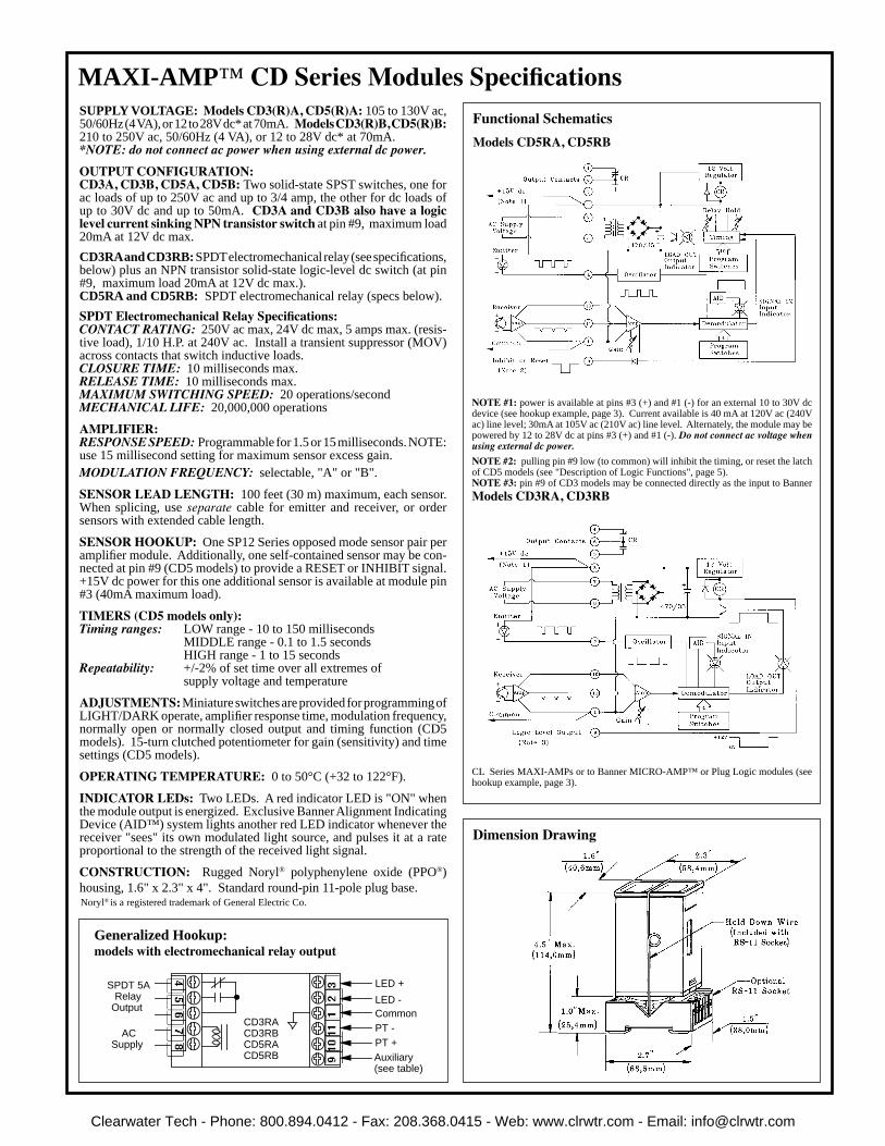
SUPPLY VOLTAGE: Models CD3(R)A, CD5(R)A: 105 to 130V ac, 50/60Hz (4 VA), or 12 to 28V dc* at 70mA. Models CD3(R)B, CD5(R)B: 210 to 250V ac, 50/60Hz (4 VA), or 12 to 28V dc* at 70mA.*NOTE: do not connect ac power when using external dc power.OUTPUT CONFIGURATION: CD3A, CD3B, CD5A, CD5B: Two solid-state SPST switches, one for ac loads of up to 250V ac and up to 3/4 amp, the other for dc loads of up to 30V dc and up to 50mA. CD3A and CD3B also have a logic level current sinking NPN transistor switch at pin #9, maximum load 20mA at 12V dc max.
CD3RA and CD3RB: SPDT electromechanical relay (see specifications, below) plus an NPN transistor solid-state logic-level dc switch (at pin #9, maximum load 20mA at 12V dc max.).CD5RA and CD5RB: SPDT electromechanical relay (specs below).
SPDT Electromechanical Relay Specifications:CONTACT RATING: 250V ac max, 24V dc max, 5 amps max. (resis-tive load), 1/10 H.P. at 240V ac. Install a transient suppressor (MOV) across contacts that switch inductive loads.CLOSURE TIME: 10 milliseconds max.RELEASE TIME: 10 milliseconds max.MAXIMUM SWITCHING SPEED: 20 operations/secondMECHANICAL LIFE: 20,000,000 operations
AMPLIFIER: RESPONSE SPEED: Programmable for 1.5 or 15 milliseconds. NOTE: use 15 millisecond setting for maximum sensor excess gain. MODULATION FREQUENCY: selectable, "A" or "B".
SENSOR LEAD LENGTH: 100 feet (30 m) maximum, each sensor. When splicing, use separate cable for emitter and receiver, or order sensors with extended cable length.
SENSOR HOOKUP: One SP12 Series opposed mode sensor pair per amplifier module. Additionally, one self-contained sensor may be con-nected at pin #9 (CD5 models) to provide a RESET or INHIBIT signal. +15V dc power for this one additional sensor is available at module pin #3 (40mA maximum load).
TIMERS (CD5 models only):Timing ranges: LOW range - 10 to 150 milliseconds MIDDLE range - 0.1 to 1.5 seconds HIGH range - 1 to 15 secondsRepeatability: +/-2% of set time over all extremes of supply voltage and temperature
ADJUSTMENTS: Miniature switches are provided for programming of LIGHT/DARK operate, amplifier response time, modulation frequency, normally open or normally closed output and timing function (CD5 models). 15-turn clutched potentiometer for gain (sensitivity) and time settings (CD5 models). OPERATING TEMPERATURE: 0 to 50°C (+32 to 122°F).
INDICATOR LEDs: Two LEDs. A red indicator LED is "ON" when the module output is energized. Exclusive Banner Alignment Indicating Device (AID™) system lights another red LED indicator whenever the receiver "sees" its own modulated light source, and pulses it at a rate proportional to the strength of the received light signal.
CONSTRUCTION: Rugged Noryl® polyphenylene oxide (PPO®) housing, 1.6" x 2.3" x 4". Standard round-pin 11-pole plug base.
Functional Schematics
NOTE #1: power is available at pins #3 (+) and #1 (-) for an external 10 to 30V dc device (see hookup example, page 3). Current available is 40 mA at 120V ac (240V ac) line level; 30mA at 105V ac (210V ac) line level. Alternately, the module may be powered by 12 to 28V dc at pins #3 (+) and #1 (-). Do not connect ac voltage when using external dc power.NOTE #2: pulling pin #9 low (to common) will inhibit the timing, or reset the latch of CD5 models (see "Description of Logic Functions", page 5).NOTE #3: pin #9 of CD3 models may be connected directly as the input to Banner Models CD3RA, CD3RB
Models CD5RA, CD5RB
Dimension Drawing
CL Series MAXI-AMPs or to Banner MICRO-AMP™ or Plug Logic modules (see hookup example, page 3).
Generalized Hookup: models with electromechanical relay output
CD3RACD3RBCD5RACD5RB
SPDT 5ARelay
Output
AC Supply 8
7
6
5
4
910
11
1
23 LED +
LED - CommonPT -
Auxiliary(see table)
PT +
Clearwater Tech - Phone: 800.894.0412 - Fax: 208.368.0415 - Web: www.clrwtr.com - Email: [email protected]

3) Power for External Devices (all models)External 10 to 30V dc devices such as self-contained sensors may be connected between terminals #3 (+) and #1 (-) of any CD series MAXI-AMP module. Terminal #3 offers 40mA maximum. This is sufficient to power most Banner self-contained dc sensors.
As the example at the right illustrates, the current sinking output of a self-contained sensor powered by the MAXI-AMP may be used as the input to the AUXILIARY terminal of a CD5 module.
See Hookup Diagram #1 (above) for load and power connection information.
2) Logic Level NPN Output (CD3 models)Typically, the CM5 module would be programmed for the ONE-SHOT or DELAYED ONE-SHOT logic func-tion. If the SP12 pair "sees" an ac-ceptable condition when the SP300D senses the leading (or trailing) edge of a product, the CD3 will inhibit a reject pulse from occuring.
The AUXILIARY terminal (#9) of models CD3A, CD3B, CD3RA and CD3RB modules offers a logic-level NPN (current sinking) output which may be used as a fast-response solid-state inhibit signal to the AUXILIARY input of MAXI-AMP CD5, CL5, CM5, or CR5 Series modules. This output may also serve as an input to any MICRO-AMP™, Plug Logic, or CL Series logic module. In addition, this output may interface to other dc devices or circuits like counters, rate meters, or programmable logic controllers. Switching capacity is 20mA at 12V dc.
The example here shows the use of SP12 Series sensors and a CD3 mod-ule to provide inspection informa-tion, with the SP300D functioning as a product (GATE) sensor.
greenblack
white
green
redblack
white
Gate(Interrogate)
Data(Inspection)
Inhibit
ACSupply
CD3models
8
7
6
5
4
910
11
1
2
3
ACSupply
CM5models
87
65
4
91011
123
SP300D
SP12 Series Emitter SP12 Series Receiver
bluebrown
NOTE: Black wire from SE612
is not used +15V dc(#3)
GATE(Interrogate)
CD5models
Inhibit
White
green
blueblack
white
ACSupply
Blue(#1)Brown
+15V dc @40mA
DATA(Inspection)SE612
8
7
6
54
91011
12
3
brown
SP12 Series Emitter SP12 Series Receiver
SP12 Series sensors are especially designed for use with CD Series modules. The basic hookup is given here. Each MAXI-AMP™ CD Series module supports use of one pair of SP12 Series sensors. CD5 Series module models also support use of a GATE or INHIBIT sensor at pin #9 (below, this page).
1) Hookup of SP12 Series Sensors (all models)
MAXI-AMP CD SeriesSP12 Sensor Hookup to CD Series MAXI-AMP™ Modules
3
SPDT 5A
RelayOutput
AC SUPPLY
*
LED + (white)
LED - (blue)
COMMON (black)
PT - (blue)
AUX
AC SUPPLY
*PT + (brown)
AC Load
DC Load
Load Common
Models with isolated solid-state contacts
LED + (white)
LED - (blue)
COMMON (black)
PT - (blue)
AUX
CD3RACD3RBCD5RACD5RB
87654
91011
123
PT + (brown)
SP12SELQDModels with electromechanical relay contacts
*105 to 130V ac or 210 to 250V ac, 50/60Hz, depending on model. To power the MAXI-AMP™ module from a dc supply, connect +12 to 28V dc at 70mA to terminal #3 and dc common to terminal #1. Make no connection to terminal #7 or #8.
SP12SRLQD
CD3ACD3BCD5ACD5B
87
65
4
910
11
123
SP12SELQD SP12SRLQD
Clearwater Tech - Phone: 800.894.0412 - Fax: 208.368.0415 - Web: www.clrwtr.com - Email: [email protected]

Factory settings are shown at left. The "underlined" settings in table below are factory settings.
Amplifier response conditions may be programmed via the group of four switches located on one of the narrow sides of the MAXI-AMP™ module.
Switch #1 selects the modulation frequency of the amplifier and the emitter light source. When two pairs of SP12 Series sensors are being used in close proximity to each other, the modulation frequency switch of their respective CD Series modules should be set to different modu-lation frequencies. This makes it possible to use the two sensor pairs in close proximity without optical crosstalk. Both amplifiers must be set for the same response time (either 1.5 or 15 milliseconds) to ensure freedom from crosstalk.
Amplifier Programming (all CD Series modules)
MAXI-AMP CD Se-
4
Switches #2 and #3 are used to program the amplifier response time. The 15 millisecond setting allows SP12 Series sensors to operate at their maximum excess gain.
Switch #4 is used to select LIGHT OPERATE or DARK OPER-ATE. In the LIGHT OPERATE mode, the output will energize (in ON/OFF or LATCH operation) or the timing function will initiate (in DELAY, ONE-SHOT, or LIMIT operation) when the receiver "sees" sufficient light (excess gain greater than 1X). In DARK OPERATE, the output will energize or timing will begin when the receiver is sufficiently dark (excess gain less than 1X). The diagram at the left shows the location of switches 1-4, and the table summarizes the settings required for each response condition.
NOTE: An adhesive-backed mylar label is supplied. It may be marked to indicate switch programming and then applied to the MAXI-AMP housing as a switch cover.
The diagram shows switch locations, and the table summarizes the program switch positions.
Settings illustrated below are factory settings, and are "underlined" in the table.
Timing Logic Programming (CD5 models)
WARNING These photoelectric sensing devices do NOT include the self-checking redundant circuitry necessary to allow their use in personnel safety applications. A sensor failure or malfunction can result in either an energized or a de-energized sensor output condition.
Never use these products as sensing devices for personnel protection. Their use as safety devices may create an unsafe condition which could lead to serious injury or death.
Only MACHINE-GUARD and PERIMETER-GUARD Systems, and other systems so designated, are designed to meet OSHA and ANSI machine safety standards for point-of-operation guarding devices. No other Banner sensors or controls are designed to meet these standards, and they must NOT be used as sensing devices for personnel protection.
A group of ten switches, located on the side of the module opposite the amplifier program switches, is used to select the timing logic for the CD5 models.
Switches #1 through #7 are used to select the logic function. Switch #8 programs the output for either NORMALLY OPEN or NORMALLY CLOSED operation. Switches #9 and #10 program the time range(s). There are three ranges: 10 to 150 milliseconds, 0.1 to 1.5 seconds, and 1 to 15 seconds. The programmed range will be the same for both functions of a dual tim-ing mode (ON & OFF DELAY, DELAYED ONE-SHOT, and REPEAT CYCLE). However, DELAY and HOLD times are independently adjustable within the selected range.
Clearwater Tech - Phone: 800.894.0412 - Fax: 208.368.0415 - Web: www.clrwtr.com - Email: [email protected]

LIMIT: The output of the LIMIT function follows the action of the input, as it does with the ON/OFF function. However, an input signal which is longer than the adjustable LIMIT ("HOLD") time will turn the output "off". Removing the input signal resets the timer. This function is sometimes called "TIME LIMITED ON/OFF", and is useful for energy conservation. Grounding pin #9 cancels the output. Lifting the inhibit restarts the LIMIT timer, if an input signal is present.
ON/OFF: ON/OFF operation does not involve timing. The output simply follows the action of the input signal. Grounding pin #9 (AUXILIARY) turns the output "off", regardless of the state of the input signal. This may be accomplished by closing a switch or relay contact between pins #9 and #1 (common), or by connecting an open collector NPN (current sinking) output of any external dc device directly to pin #9. NOTE: connect the COMMON of any external dc device to pin #1 of the MAXI-AMP to establish a voltage reference between the dc supply for the external device and the internal dc
ON DELAY: The ON DELAY timer keeps the output "off" until the selected LIGHT or DARK signal has been pres-ent for the preset "DELAY" time. If the input signal is interrupted, the timing is reset and starts over with the next signal. Grounding pin #9 immediately cancels an output in progress and resets the delay timer. The delay timer is restarted when the inhibit signal is removed, if an input signal is present.
OFF DELAY: The output energizes immediately when the input signal occurs, but does not de-energize until the signal has been removed for the preset OFF-DELAY ("HOLD") time. Grounding pin #9 prevents an output from occuring.
ON & OFF DELAY: ON and OFF DELAY logic combines both timing functions into a single mode. The ON-DELAY ("DELAY") time and the OFF-DELAY ("HOLD") time are independently adjustable within the selected time range. Momentary grounding of pin #9 during the ON-DELAY period resets the DELAY timer. An inhibit signal which occurs during an output will allow the output to stay energized for the remainder of the OFF-DELAY time. ON and OFF DELAY logic is often used in jam and void control, high/low level control, and edge-guiding applications.
ONE-SHOT: The output of a ONE-SHOT function is a pulse of adjustable "HOLD" duration which is independent of the duration of the input signal. With the MAXI-AMP programmed for LIGHT operate, the pulse occurs when the input signal changes from dark to light. In DARK operate, the pulse occurs with a light to dark input transition. Grounding pin #9 prevents the one-shot from triggering, but does not affect a pulse already under way.
DELAYED ONE-SHOT: A DELAYED ONE-SHOT is initiated by either a momentary or maintained input signal. This input starts the adjustable "DELAY" period, after which the output pulses for an adjustable pulse ("HOLD") time. No further action occurs unless the input is removed and reapplied, beginning a new sequence. Grounding pin #9 during the delay period will cancel the sequence, and no output occurs. This feature is often used for inspection/rejection control logic. An inhibit signal will not affect a pulse under way.
REPEAT CYCLE: The REPEAT CYCLE function provides an oscillating output when an input signal is present. Presence of an input signal triggers an adjustable "DELAY" timer. After the delay, the output energizes for an adjustable "HOLD" period. If the input remains, the output continues to cycle "on" and "off" at this rate indefinitely. When the signal is removed, any output in progress completes and then remains "off" until the next signal and DELAY period. Grounding pin #9 cancels the sequence, but will allow the completion of a "HOLD" period in progress. Lifting the inhibit signal begins
AC LATCH: An AC LATCH is the combination of a ONE-SHOT and a LATCH. A momentary or sustained input will latch the output "on". Grounding pin #9 will reset the latch, even if the input signal remains. The output will not re-latch until the input signal is removed and then reapplied.
DC LATCH: The output will latch "on" whenever the selected LIGHT or DARK input condition occurs. Grounding pin #9 of a dc latch will turn the output "off" regardless of the state of the input signal. If the signal is present when the reset is removed, the output will immediately latch "on" again.
DELAY AND LATCH: The DELAY + LATCH is a combination of the ON-DELAY and DC LATCH functions. An input must be present for at least the adjustable "DELAY" time for the output to latch "on". If the input signal is removed during the timing cycle, the timing is reset. Momentary grounding of pin #9 resets the latch and/or the DELAY timing cycle. Sustained grounding of pin #9 inhibits any output.
LIMIT AND LATCH: The LIMIT + LATCH operates exactly like the LIMIT function, except that the LIMIT ("HOLD") timer can be reset only by the auxiliary input. An output remains latched "off" until reset by momentarily ground-ing pin #9. In addition to resetting the timer, grounding pin #9 will hold the output "off", regardless of the state of the input signal.
Description of Logic Functions, CD5 models
5Clearwater Tech - Phone: 800.894.0412 - Fax: 208.368.0415 - Web: www.clrwtr.com - Email: [email protected]

MAXI-AMP System Mounting and Accessories
After the panel cutout has been completed and de-burred, slide the MAXI-AMP through the cutout and place one clip assembly into the rectangular depression on each of the two narrow sides of the housing. Orient clips as shown, and alternately tighten the screws for equal pressure against the inside of the panel wall. Do not overtighten the screws. Attach the optional EC11-6 extension cable (described below) to the MAXI-AMP and route the opposite end of the cable to the RS-11 (or equivalent) socket.
Model EC11-6 extension cable is 6 feet (2m) long. Clips for panel wall mounting of the MAXI-AMP are included with the cable.
Banner Engineering Corp. 9714 Tenth Ave. No. Minneapolis, MN 55441 Telephone: (763) 544-3164 FAX (applications): (763) 544-3573
Model RS-11 Socket
The RS-11 is supplied with a coding ring and pin (see diagram at right). This allows a MAXI-AMP to be keyed to fit only its own 11-pin socket. The pin is installed in one of the eleven slots in the RS-11, and the notch in the ring is aligned to slip over the pin. When the MAXI-AMP is removed from the RS-11, the coding ring stays with the MAXI-AMP base, while the coding pin remains in the socket.
Model RS-11 is an eleven-pole round-pin screw terminal relay socket which is used to make electri-cal connections to any MAXI-AMP module. The socket provides in-line wire clamp screw terminals which will accept from one #24 AWG up to two #14 wires at each pin. The RS-11 is UL recognized (file #E92191) and CSA approved (file #LR38486). It may be mounted directly to a panel plate or via standard 35mm DIN-rail track (see below). A hold-down wire is supplied with each RS-11 socket (see dimension diagram on page 2).
Accessories for MAXI-AMP Modules
Model BENC-4 EnclosureModel BENC-4 is a NEMA-4 rated corrosion-resistant enclosure for a MAXI-AMP module or other control device. It is supplied with a DIN-35-70 track for easy mounting of one RS-11 socket. For mounting two sockets, use DIN-35-105.
WARRANTY: Banner Engineering Corporation warrants its products to be free from defects for one year. Banner Engineering Corporation will repair or replace, free of charge, any product of its manufacture found to be defective at the time it is returned to the factory during the warranty period. This warranty does not cover damage or liability for the improper application of Banner products. This warranty is in lieu of any other warranty either expressed or implied.
Panel Wall Mounting of MAXI-AMP Module
Track model DIN-35-70 accomodates one RS-11 socket. Model DIN-35-105 holds two sockets. Model DIN-35-140 holds up to three sockets. The RS-11 socket is designed to snap (or slide) directly into the 35mm DIN track.
35mm DIN Rail Track
Clearwater Tech - Phone: 800.894.0412 - Fax: 208.368.0415 - Web: www.clrwtr.com - Email: [email protected]

Printed in USA P/N 32882
•
•
•
•
Versatile, cost-effective sensor control modules: modelsavailable for use with most Banner photoelectric sensors
Power supply, photoelectric amplifier (CD and CMSeries), programmable timing logic (CD5, CM5, and CL5models), and output relay in a single, compact plug-inmodule
CD5, CL5, and CM5 models include 12 selectable delay,pulse, and latch timing logic functions(single or dual functions)
All models have 5-amp SPDT electromechanical relayoutput (solid-state switch optional); some models offeradditional solid-state dc switch (see table, page 2)
MAXI-AMP ® SystemStand-alone sensor control modules
Product
Line Specifications
Clearwater Tech - Phone: 800.894.0412 - Fax: 208.368.0415 - Web: www.clrwtr.com - Email: [email protected]

CM Series MAXI-AMPmodules contain amodulated photoelectricamplifier for use with thefull complement ofBanner high perform-ance modulated remotesensors (pp. 13-17).
CD Series MAXI-AMPmodules contain amodulated photoelectricamplifier for use withSP12 Series preamplifiedremote sensors(pp. 7-9).
See pages18-21
ON/OFF(output follows input)
105 to 130V acor210 to 250V ac
210 to 250V ac, or12 to 28V dc
See page 22
SPDT E/M relay, isolat-ed solid state DC switch
SPDTelectromechanical relay
105 to 130V ac, or12 to 28V dc210 to 250V ac, or12 to 28V dc
105 to 130V ac, or12 to 28V dc
210 to 250V ac, or12 to 28V dc
105 to 130V ac, or12 to 28V dc
210 to 250V ac, or12 to 28V dc
Supplies 400mA to powerMAXI-AMP modulesand/or other 10-30V dcsensing devices.
SPDT electromechani-cal relay, plus NPNtransistor solid-stateswitch
105 to 130V ac, or12 to 28V dc
ON/OFF(output follows input)
ON/OFF(output follows input)
SUPPLYVOLTAGE
USED WITH (INPUT)
LOGICFUNCTION(S)
REFER TOPAGES ...
MODULEMODEL
210 to 250V ac, or12 to 28V dc
SPDTelectromechanical relay
105 to 130V ac, or12 to 28V dc210 to 250V ac, or12 to 28V dc
105 to 130V ac, or12 to 28V dc ON/OFF
(output follows input)CD3RA
CD3RB
CD5RA
CD5RB
CM3RA
CM3RB
CM5RA
CM5RB
CL3RA
CL3RB
CL5RA
CL5RB
CI3RC
CP12RC
CP12C
™
Banner MAXI-AMPs are the most versatile and cost-effectivesensor control modules available anywhere. MAXI-AMP systemmodules combine power supply, photoelectric amplifier (CD andCM series), programmable timing logic (CD5, CM5, and CL5models), and output relay in a single, compact plug-in module. Thisintegrated stand-alone design saves both the expense of a separatecontrol chassis and a substantial amount of control panel space.MAXI-AMP modules are powered directly by AC line voltage.Models are available for either 120V ac or 220/240V ac operation.
CD Series MAXI-AMP modules accept input signals from SP12Series preamplified remote sensors. The preamplified design ofthis system produces exceptionally high noise immunity.
CM Series MAXI-AMPs are designed to work with the popular lineof Banner high-performance modulated remote sensors. The CRSeries is a low-gain version of the CM Series, and is designed foruse with the SP100 Series miniature remote sensors.
CL Series MAXI-AMP modules accept input signals from any
Banner dc module and most dc self-contained sensors.
CI Series MAXI-AMPs provide the power supply, current ampli-fier, and output device for an SMI912 Series intrinsically safesensor. CI Series modules are covered in data sheet P/N 03461.
CD5, CM5, and CL5 models include a multi-function timing logiccircuit, which is easily programmed for twelve of the most popularand useful delay, pulse, and latch functions. MAXI-AMPs offer thechoice of either single or dual timing functions in the same module.
MAXI-AMPs offer a 5-amp SPDT electromechanical relay output.Solid-state switches are available as an option. CD3, CM3 and CL3models offer an additional solid state dc switch.
MAXI-AMPs are contained in a tough NORYL® housing whichmeasures a compact 1.6 x 2.3 x 4". Electrical connections are madevia any standard 11-pole round-pin relay socket (model RS-11).
All MAXI-AMP system modules (except model CI3RC) are CSAcertified and UL recognized.
SPDT electromechani-cal relay, plus NPNtransistor solid-stateswitch
MAXI-AMP SystemStand-alone Sensor Control Modules
See data sheet 03461SMI912 series intrinsicallysafe sensors.
SPDT electro-mechanical relay
2
CL Series modulesaccept signals from anyBanner DC sensor ormodule with NPN(current sinking) output. SPDT
electromechanical relay
No logic function(power supply only)
No output device(power supply only)
Selection of 12 prog-rammable functionsincluding delay, pulse,limit, cycle, and latch
Selection of 12 prog-rammable functionsincluding delay, pulse,limit, cycle, and latch
Selection of 12 prog-rammable functionsincluding delay, pulse,limit, cycle, and latch
SPDT electromechani-cal relay, plus NPNtransistor solid-stateswitch See pages
3-9
See pages10-17
OUTPUTCONFIGURATION
Clearwater Tech - Phone: 800.894.0412 - Fax: 208.368.0415 - Web: www.clrwtr.com - Email: [email protected]

™
•
•
•
•
•
•
3
LOGICOUTPUT
ON/OFF
12timingfunctions
SPDT electro-mechanicalrelay, plusNPN transistorsolid-stateswitch
SPDT electro-mechanicalrelay (5 ampcontact rating)
105 to 130V ac, or12 to 28V dc
210 to 250V ac, or12 to 28V dc
105 to 130V ac, or12 to 28V dc
210 to 250V ac, or12 to 28V dc
MODEL
CD3RA
CD3RB
CD5RA
CD5RB
LOGICOUTPUT
ON/OFF
12timingfunctions
105 to 130V ac, or12 to 28V dc
210 to 250V ac, or12 to 28V dc
105 to 130V ac, or12 to 28V dc
210 to 250V ac, or12 to 28V dc
CD3A
CD3B
CD5A
CD5B
MODELSUPPLY
VOLTAGE
SPST solid-state contactfor switchingAC loads upto 250V acand 3/4 amp,plus solid-state contactfor switchingDC loads upto 30V dc andup to 50mA.
45678
321
11109
LED +
LED -
PT -
PT +
Auxiliary(see table)
CD3A CD3B CD5A CD5B
Common
ACSupply
DC load
AC load
Load common
Isolatedsolid-state contacts:
Generalized Hookup: models with solid-state output
MAXI-AMP™ CD Series amplifier and control modules aredesigned to operate with SP12 Seriessensors (foreground, see page 7).
SUPPLYVOLTAGE
Programmable Modulated Amplifier and Control Modulesfor use with SP12 Series Preamplified Remote Photoelectric Barrel Sensors
MAXI-AMP CD Series
CD Series MAXI-AMP modules combine power supply, modulatedphotoelectric amplifier, timing logic (in CD5 models) and outputswitch in a single compact, cost-saving module. CD Series moduleswork together with Banner SP12 Series preamplified remote sensors.These sensors offer small size and high power, and are built to operatein highly demanding sensing environments. Their preamplified designgives them exceptionally high immunity to electrical noise (see page 7for further information). MAXI-AMP modules themselves are alsoruggedly built for dependable industrial duty.
CD Series MAXI-AMP modules contain a state-of-the-art BannerCMOS modulator/demodulator/amplifier circuit that offers high im-munity to both ambient light and electrical interference plus reliablesensor performance. All models have Banner's exclusive, patentedAlignment Indicating Device (AID™) system, which lights an LEDindicator whenever the receiver sees a "light" condition, and pulses theLED at a rate proportional to the received light signal strength. MAXI-AMP modules operate from a variety of voltages (see tables at right).
All CD Series modules are programmable for LIGHT or DARK oper-ate. Module input response time may be set at either 1.5 or 15 milli-seconds. The 15-millisecond response mode offers maximum sensingpower (excess gain) with SP12 Series sensors. CD Series modules alsofeature selectable sensor modulation frequencies ("A" and "B"). Thismakes it possible to operate two high-powered SP12 Series sensor pairsusing different modulation frequencies (at the same response timesetting) in close proximity to each other without optical crosstalk.
CD5 models include a versatile multi-function timing logic circuit thatis programmable for 12 popular and useful delay, one-shot, and latchfunctions. Each timing function has a choice of three time ranges.Timing and sensitivity adjustments use rugged 15-turn potentiometersfor very accurate settings. CD Series module circuit design preventsfalse outputs on system power-up.
The output circuit for CD3A, 3B, 5A, and 5B modules consists of twoSPST solid-state switches: one for ac loads of up to 250V ac (3/4 amp),and a second for dc loads of up to 30V dc (50 mA). Models CD5RAand CD5RB have a 5-amp SPDT electromechanical relay. CD3RA andCD3RB modules have a 5-amp SPDT electromechanical relay plus anNPN transistor solid-state switch. For more information on outputcircuit load capability, refer to the tables (right) and the Specificationssection on the next page.
Modulated photoelectric amplifier, power supply,output relay, and versatile timing logic (CD5 models)in one compact, stand-alone package
120 or 240V ac or 12-28V dc operation; requires onlythe addition of a Banner SP12 preamplified opposedmode sensor pair to create a powerful sensing system
CD5 models are easily programmed for any of twelvedelay, one-shot, and latch functions (either single ordual timing); interrogation schemes are possibleusing auxiliary input
Exceptionally high immunity to ambient light andelectrical noise; no false pulse on power-up
Rugged, 15-turn potentiometers for precise timingand sensitivity adjustment; tough Noryl® housing
Includes Banner's exclusive AID™ alignment system
Clearwater Tech - Phone: 800.894.0412 - Fax: 208.368.0415 - Web: www.clrwtr.com - Email: [email protected]

MAXI-AMP™ CD Series Modules Specifications
4
Noryl® is a registered trademark of General Electric Co.
SUPPLY VOLTAGE: Models CD3(R)A, CD5(R)A: 105 to 130V ac,50/60Hz (4 VA), or 12 to 28V dc* at 70mA. Models CD3(R)B,CD5(R)B: 210 to 250V ac, 50/60Hz (4 VA), or 12 to 28V dc* at 70mA.*NOTE: do not connect ac power when using external dc power.
OUTPUT CONFIGURATION:CD3A, CD3B, CD5A, CD5B: Two solid-state SPST switches, one forac loads of up to 250V ac and up to 3/4 amp, the other for dc loads of upto 30V dc and up to 50mA. CD3A and CD3B also have a logic levelcurrent sinking NPN transistor switch at pin #9, maximum load 20mAat 12V dc max.
CD3RA and CD3RB: SPDT electromechanical relay (see specifica-tions, below) plus an NPN transistor solid-state logic-level dc switch (atpin #9, maximum load 20mA at 12V dc max.).CD5RA and CD5RB: SPDT electromechanical relay (specs below).
SPDT Electromechanical Relay Specifications:CONTACT RATING: 250V ac max, 24V dc max, 5 amps max.(resistive load), 1/10 H.P. at 240V ac. Install a transient suppressor(MOV) across contacts that switch inductive loads.CLOSURE TIME: 10 milliseconds max.RELEASE TIME: 10 milliseconds max.MAXIMUM SWITCHING SPEED: 20 operations/secondMECHANICAL LIFE: 20,000,000 operations
AMPLIFIER:RESPONSE SPEED: Programmable for 1.5 or 15 milliseconds. NOTE:use 15 millisecond setting for maximum sensor excess gain.MODULATION FREQUENCY: selectable, "A" or "B".
SENSOR LEAD LENGTH: 100 feet (30 m) maximum, each sensor.When splicing, use separate cable for emitter and receiver, or ordersensors with extended cable length.
SENSOR HOOKUP: One SP12 Series opposed mode sensor pair peramplifier module. Additionally, one self-contained sensor may beconnected at pin #9 (CD5 models) to provide a RESET or INHIBITsignal. +15V dc power for this one additional sensor is available atmodule pin #3 (40mA maximum load).
TIMERS (CD5 models only):Timing ranges: LOW range - 10 to 150 milliseconds
MIDDLE range - 0.1 to 1.5 secondsHIGH range - 1 to 15 seconds
Repeatability: +/-2% of set time over all extremes ofsupply voltage and temperature
ADJUSTMENTS: Miniature switches are provided for programmingof LIGHT/DARK operate, amplifier response time, modulation fre-quency, normally open or normally closed output and timing function(CD5 models). 15-turn clutched potentiometer for gain (sensitivity) andtime settings (CD5 models).
OPERATING TEMPERATURE: 0 to 50°C (+32 to 122°F).
INDICATOR LEDs: Two LEDs. A red indicator LED is "ON" whenthe module output is energized. Exclusive Banner Alignment IndicatingDevice (AID™) system lights another red LED indicator whenever thereceiver "sees" its own modulated light source, and pulses it at a rateproportional to the strength of the received light signal.
CONSTRUCTION: Rugged Noryl® polyphenylene oxide (PPO®)housing, 1.6" x 2.3" x 4". Standard round-pin 11-pole plug base.
Functional Schematics
NOTE #1: power is available at pins #3 (+) and #1 (-) for an external 10 to 30V dcdevice (see hookup example, page 9). Current available is 40 mA at 120V ac (240Vac) line level; 30mA at 105V ac (210V ac) line level. Alternately, the module may bepowered by 12 to 28V dc at pins #3 (+) and #1 (-). Do not connect ac voltage whenusing external dc power.
NOTE #2: pulling pin #9 low (to common) will inhibit the timing, or reset the latchof CD5 models (see "Description of Logic Functions", page 6).
Models CD3RA, CD3RB
Models CD5RA, CD5RB
Dimension Drawing
NOTE #3: pin #9 of CD3 models may be connected directly as the input to Banner CLSeries MAXI-AMPs or to Banner MICRO-AMP™ or Plug Logic modules (seehookup example, page 9).
Generalized Hookup:models with electromechanical relay output
CD3RACD3RBCD5RACD5RB
SPDT 5ARelay
Output
AC Supply 8
76
54
910
111
23 LED +
LED - CommonPT -
Auxiliary(see table)
PT +
Clearwater Tech - Phone: 800.894.0412 - Fax: 208.368.0415 - Web: www.clrwtr.com - Email: [email protected]

Amplifier Programming (all CD Series modules)
The diagram at the left shows the location of switches 1-4,and the table summarizes the settings required for eachresponse condition.
NOTE: An adhesive-backed mylar label is supplied. It maybe marked to indicate switch programming and then ap-plied to the MAXI-AMP housing as a switch cover.
Factory settings areshown at left. The"underlined" settings intable below are factorysettings.
OFF
ON
OFF
AMPLIFIERPROGRAMMING #1 #2 #3 #4
SWITCH SWITCH SWITCH SWITCH
ON
O
F
F
1
2
3
4
Modulation freq. "A"
1.5 millisecond response
15 millisecond response
Light operate
Dark operate
ON
ON
OFF
Modulation freq. "B"
OFF
ON
ON
OFFON
ON ON ON OFF ON OFF ON
PROGRAMMINGTIMING LOGIC
#1 #2 #3 #4 #5 #6 #7 #8 #9 #10
10
ON
O
F1
2
4
3
F
5
6
7
8
9
SWITCH SWITCH SWITCH SWITCH
ON
ON
ONON
OFF
OFF
OFF
SWITCH SWITCH SWITCH SWITCH SWITCH SWITCH
On/Off
On Delay
Off Delay
On and Off Delay
One-shot
Delayed One-shot
Limit
Repeat Cycle
AC Latch
DC Latch
Delay and Latch
Limit and Latch
ON ON OFF ON OFF ON
OFF OFFOFF OFF ON
ONOFFOFF OFF ON OFF ON
OFF OFFOFF OFF OFF
ON ON ONOFFOFF OFFOFF
OFF ON ON OFF ON
OFF ON ON OFF
ON
ONONON
ONON OFF ONONON
ON ON OFF OFF ONONON
ON ON OFF OFF OFF ONON
N/C Output
N/O Output
.15 Sec. Max. Time
1.5 Sec. Max. Time
15 Sec. Max. Time
OFF
OFF OFF
OFF ON
ON OFF ON OFF ON OFF ON
5
A group of ten switches, located on the side of the module opposite the amplifier programswitches, is used to select the timing logic for the CD5 models.
Switches #1 through #7 are used to select the logic function. Switch #8 programs the output foreither NORMALLY OPEN or NORMALLY CLOSED operation. Switches #9 and #10program the time range(s). There are three ranges: 10 to 150 milliseconds, 0.1 to 1.5 seconds,and 1 to 15 seconds. The programmed range will be the same for both functions of a dual timingmode (ON & OFF DELAY, DELAYED ONE-SHOT, and REPEAT CYCLE). However,DELAY and HOLD times are independently adjustable within the selected range.
The diagram shows switch locations, and thetable summarizes the program switch posi-tions.
tion frequencies. This makes it possible to use the two sensor pairsin close proximity without optical crosstalk. Both amplifiers mustbe set for the same response time (either 1.5 or 15 milliseconds) toensure freedom from crosstalk.
Switches #2 and #3 are used to program the amplifier responsetime. The 15 millisecond setting allows SP12 Series sensors tooperate at their maximum excess gain.
Switch #4 is used to select LIGHT OPERATE or DARK OPER-ATE. In the LIGHT OPERATE mode, the output will energize (inON/OFF or LATCH operation) or the timing function will initiate (inDELAY, ONE-SHOT, or LIMIT operation) when the receiver"sees" sufficient light (excess gain greater than 1X). In DARKOPERATE, the output will energize or timing will begin when thereceiver is sufficiently dark (excess gain less than 1X).
Amplifier response conditions may be programmed via the group of fourswitches located on one of the narrow sides of the MAXI-AMP™module.
Switch #1 selects the modulation frequency of the amplifier and theemitter light source. When two pairs of SP12 Series sensors are beingused in close proximity to each other, the modulation frequency switchof their respective CD Series modules should be set to different modula-
Settings illustrated below are factory settings. Factory settings are "underlined" in the table.
Timing Logic Programming (CD5 models)
Clearwater Tech - Phone: 800.894.0412 - Fax: 208.368.0415 - Web: www.clrwtr.com - Email: [email protected]

LIMIT: The output of the LIMIT function follows the action of the input, as it does with the ON/OFF function. However,an input signal which is longer than the adjustable LIMIT ("HOLD") time will turn the output "off". Removing the input signalresets the timer. This function is sometimes called "TIME LIMITED ON/OFF", and is useful for energy conservation.Grounding pin #9 cancels the output. Lifting the inhibit restarts the LIMIT timer, if an input signal is present.
ON/OFF: ON/OFF operation does not involve timing. The output simply follows the action of the input signal.Grounding pin #9 (AUXILIARY) turns the output "off", regardless of the state of the input signal. This may be accomplishedby closing a switch or relay contact between pins #9 and #1 (common), or by connecting an open collector NPN (current sinking)output of any external dc device directly to pin #9. NOTE: connect the COMMON of any external dc device to pin #1 of theMAXI-AMP to establish a voltage reference between the dc supply for the external device and the internal dc supply of theMAXI-AMP.
ON DELAY: The ON DELAY timer keeps the output "off" until the selected LIGHT or DARK signal has been presentfor the preset "DELAY" time. If the input signal is interrupted, the timing is reset and starts over with the next signal. Groundingpin #9 immediately cancels an output in progress and resets the delay timer. The delay timer is restarted when the inhibit signalis removed, if an input signal is present.
OFF DELAY: The output energizes immediately when the input signal occurs, but does not de-energize until the signalhas been removed for the preset OFF-DELAY ("HOLD") time. Grounding pin #9 prevents an output from occuring. If aninhibit input occurs during an output, the output remains "on" for the remainder of the OFF-DELAY time.
ON & OFF DELAY: ON and OFF DELAY logic combines both timing functions into a single mode. The ON-DELAY ("DELAY") time and the OFF-DELAY ("HOLD") time are independently adjustable within the selected time range.Momentary grounding of pin #9 during the ON-DELAY period resets the DELAY timer. An inhibit signal which occurs duringan output will allow the output to stay energized for the remainder of the OFF-DELAY time. ON and OFF DELAY logic isoften used in jam and void control, high/low level control, and edge-guiding applications.
ONE-SHOT: The output of a ONE-SHOT function is a pulse of adjustable "HOLD" duration which is independentof the duration of the input signal. With the MAXI-AMP programmed for LIGHT operate, the pulse occurs when the inputsignal changes from dark to light. In DARK operate, the pulse occurs with a light to dark input transition. Grounding pin #9prevents the one-shot from triggering, but does not affect a pulse already under way.
DELAYED ONE-SHOT: A DELAYED ONE-SHOT is initiated by either a momentary or maintained inputsignal. This input starts the adjustable "DELAY" period, after which the output pulses for an adjustable pulse ("HOLD") time.No further action occurs unless the input is removed and reapplied, beginning a new sequence. Grounding pin #9 during thedelay period will cancel the sequence, and no output occurs. This feature is often used for inspection/rejection control logic.An inhibit signal will not affect a pulse under way.
REPEAT CYCLE: The REPEAT CYCLE function provides an oscillating output when an input signal is present.Presence of an input signal triggers an adjustable "DELAY" timer. After the delay, the output energizes for an adjustable"HOLD" period. If the input remains, the output continues to cycle "on" and "off" at this rate indefinitely. When the signalis removed, any output in progress completes and then remains "off" until the next signal and DELAY period. Grounding pin#9 cancels the sequence, but will allow the completion of a "HOLD" period in progress. Lifting the inhibit signal begins theDELAY period, if an input signal is present.
AC LATCH: An AC LATCH is the combination of a ONE-SHOT and a LATCH. A momentary or sustained inputwill latch the output "on". Grounding pin #9 will reset the latch, even if the input signal remains. The output will not re-latchuntil the input signal is removed and then reapplied.
DC LATCH: The output will latch "on" whenever the selected LIGHT or DARK input condition occurs. Groundingpin #9 of a dc latch will turn the output "off" regardless of the state of the input signal. If the signal is present when the resetis removed, the output will immediately latch "on" again.
DELAY AND LATCH: The DELAY + LATCH is a combination of the ON-DELAY and DC LATCH functions.An input must be present for at least the adjustable "DELAY" time for the output to latch "on". If the input signal is removedduring the timing cycle, the timing is reset. Momentary grounding of pin #9 resets the latch and/or the DELAY timing cycle.Sustained grounding of pin #9 inhibits any output.
LIMIT AND LATCH: The LIMIT + LATCH operates exactly like the LIMIT function, except that the LIMIT("HOLD") timer can be reset only by the auxiliary input. An output remains latched "off" until reset by momentarily groundingpin #9. In addition to resetting the timer, grounding pin #9 will hold the output "off", regardless of the state of the input signal.
Description of Logic Functions for CD5, CL5, CM5, and CR5 models
6 Clearwater Tech - Phone: 800.894.0412 - Fax: 208.368.0415 - Web: www.clrwtr.com - Email: [email protected]

SP12 Series Opposed Mode Remote Modulated Barrel Sensorsfor use with MAXI-AMP CD Series Modules
Model Type Housing Material
SP12SEL
SP12PEL
SP12SRL
SP12PRL
Emitter
Emitter
Receiver
Receiver
Stainless steel
VALOX ®
Stainless steel
VALOX ®
NOTE: Models with 30-foot attached cable are available (contact factoryfor information). 2- and 3-conductor 50- and 100-foot extension cables(without connectors) are also available. For 2-conductor (emitter) cable:order model EC12E-50 (50') or model EC12E-100 (100'). For 3-conductor(receiver) cable: order model EC12R-50 (50') or model EC12R-100 (100').
SP12 Series Barrel Sensors
VALOX ® is a registered trademark of General Electric Co.
10
0
DISTANCE
100
1000
1 FT
SP12 Seriesopposed modeemitters and receivers
10 FT 100 FT 1000FT
EXCESS
GAINI
15ms response
1.5ms response
Beam PatternExcess Gain Curve
400
0
INCHES
OPPOSED DISTANCE--FEET
80 120 160 200
20
40
60
20
40
60
SP12 Series emitters and receivers
1.5ms response
15ms response
Banner SP12 Series sensors are a family of powerful, modulated,totally-encapsulated opposed mode remote sensor pairs in compact,threaded-barrel type housings. They are the ideal choice for applica-tions that require high excess gain together with small size in difficultsensing environments. SP12 Series sensors are especially effective atpenetrating heavy contaminants when used at close range.
The preamplified design of these sensors results in exceptional noiseimmunity. Signals carried along remote receiver cables are oftensubject to interference (from electrical noise sources) that can be asstrong as (or stronger than) the desired light signal. The severity of thisproblem often worsens with increasing sensor cable length. SP12Series receivers contain a preamplifier that immediately boosts thereceived light signal to a high level before sending it down the cable tothe rest of the sensing system.
SP12 Series sensors are designed for use with the Banner CD SeriesMAXI-AMP™ modules. CD Series modules provide sensor power,additional amplification, a choice of several programmable timinglogic functions (CD5 models), and output circuitry for interfacing toa load. They also allow two different programmable sensor modulationfrequencies, making it possible to use multiple high-powered sensorpairs in close proximity to each other without optical crosstalk. CDSeries modules are available for a wide range of supply voltages. EachCD module powers one SP12 emitter/receiver pair. See page 3 for moreinformation.
SP12 sensors are rated NEMA 6P (IEC IP67) for use in wet locations.There is a choice of either VALOX® or stainless steel housing style (seetable, below). Positive sealing at both ends of the sensors, with noexposed epoxy interfaces, eliminates all leak paths (including capillaryleakage). Electronics are fully encapsulated for maximum resistance tomechanical shock and vibration. Lenses are acrylic, and quad-ringsealed. These sensors may be used with watertight, thread-on aper-tures to create very narrow, very powerful effective beams (see nextpage).
A 1/2" clearance hole is required for mounting. Alternatively, theBanner model SMB12MM mounting bracket may be used (see nextpage). SP12 Series sensors are supplied with 6-1/2 feet of PVC-covered attached cable, or QD connectors (page 8). Options for modelswith attached cable are summarized below. The maximum recom-mended emitter or receiver cable length is 100 feet (each).
Leakproof NEMA 6P threaded-barrel opposed moderemote sensor pairs; VALOX® or stainless steel housing
Compact and powerful: 1/2" (12mm) in diameter by 2"long; 200-foot sensing range. Apertures are available.
Special preamplified circuit design for noise immunityequal to that of self-contained sensors
SUPPLY VOLTAGE: sensors are powered from a Banner CD SeriesMAXI-AMP™ module (see page 3).RANGE: up to 200 feet in opposed mode (see gain curve, above).
RESPONSE SPEED: selectable for 1.5 or 15 milliseconds; a functionof the MAXI-AMP CD Series module.
LIGHT BEAM: infrared LED, 880nm. Effective beam diameter: 3/8".
CONSTRUCTION: NEMA 6P.12mm diameter tubular threaded VALOX® or stainless steel housing;positive sealing at both ends, quad-ring sealed acrylic lens. Electronicsfully epoxy-encapsulated. Two jam nuts are provided: VALOX® forVALOX ® units; stainless steel for stainless steel units. Mountingrequires 1/2" diameter clearance hole.OPERATING TEMPERATURE: -40 to +70°C (-40 to +158°F).
CABLE: sensors are supplied with 6-1/2 feet of PVC-covered 2- or 3-conductor cable. Models with QD connectors are available (page 8).
Dimension Drawing
•
•
•
Specifications, SP12 Sensors
SP12 Series sensors (foreground) shown with MAXI-AMP™CD Series amplifier and logicmodules (see pages 3-6).
Models are also available with QD connectors (page 8).
7
MAXI-AMP ™ System
Clearwater Tech - Phone: 800.894.0412 - Fax: 208.368.0415 - Web: www.clrwtr.com - Email: [email protected]

Model SMB12MM Mounting Bracket
Model SMB12MM is a stainless steel mounting bracket for SP12Series sensors. The sensor mounts to the bracket using the two jamnuts supplied with the sensor. This rugged, slotted bracket allows±10 degrees of lateral movement. Bracket is 12-gauge stainlesssteel. The bracket mounting holes accommodate #8 hardware.
Dimensional Information for MQDC-415 Cable Dimensional Information for MQDC-415RA Cable
SP12 Series Opposed Mode Remote Modulated Barrel Sensorswith Quick Disconnect (QD) Cable Option
AperturesRectangular and circular thread-on water-tight apertures are available for SP12sensors. Apertures are used to shape andsize the sensor's effective beam and toprotect the sensor's lens. Use of apertureswith these high-gain sensors makes itpossible to create very narrow, concentrated sensing beams fordemanding applications. Aperture Kit AP12SC includes threeround apertures with openings of .02", .04". and .10" diameter.Aperture kit AP12SR has three rectangular apertures .02", .04",and .10" wide. Both include lens, o-rings, and thread-on housing.
The stainless steel models of SP12 Series modulated remote barrel sensorsmay be ordered with a built-in connector designed to mate with eurofast™quick-disconnect (QD) cables. The resultant sensor model numbers are:
SP12SELQD (emitter), and
SP12SRLQD (receiver).
The mating cables are ordered separately. Cables are available in 15 footlengths with either of two styles of mating connector. Cable model MQDC-415 has a straight connector, and model MQDC-415RA has a right-angledconnector (see drawings below). In both models, the plug body is moldedto the PVC cable for waterproof integrity. Plug contacts are gold-plated.
Dimension Drawing
SMB12MM bracket:
White wire
Blue wire
Black wire
Brown wire
White wire
Blue wire
Black wire
Brown wire
8Clearwater Tech - Phone: 800.894.0412 - Fax: 208.368.0415 - Web: www.clrwtr.com - Email: [email protected]

3) Power for External Devices (all models)External 10 to 30V dc devices such asself-contained sensors may be connectedbetween terminals #3 (+) and #1 (-) ofany CD series MAXI-AMP module.Terminal #3 offers 40mA maximum.This is sufficient to power most Bannerself-contained dc sensors.
As the example at the right illustrates,the current sinking output of a self-contained sensor powered by the MAXI-AMP may be used as the input to theAUXILIARY terminal of a CD5 mod-ule.
See Hookup Diagram #1 (above) for load and power connection information.
2) Logic Level NPN Output (CD3 models)Typically, the CM5 module wouldbe programmed for the ONE-SHOTor DELAYED ONE-SHOT logicfunction. If the SP12 pair "sees" anacceptable condition when theSP300D senses the leading (or trail-ing) edge of a product, the CD3 willinhibit a reject pulse from occuring.
The AUXILIARY terminal (#9) of models CD3A, CD3B, CD3RA andCD3RB modules offers a logic-level NPN (current sinking) output which maybe used as a fast-response solid-state inhibit signal to the AUXILIARY inputof MAXI-AMP CD5, CL5, CM5, or CR5 Series modules. This output mayalso serve as an input to any MI-CRO-AMP™, Plug Logic, or CLSeries logic module. In addition,this output may interface to other dcdevices or circuits like counters,rate meters, or programmable logiccontrollers. Switching capacity is20mA maximum at 12V dc max.
The example here shows the use ofSP12 Series sensors and a CD3 mod-ule to provide inspection informa-tion, with the SP300D functioningas a product (GATE) sensor.
greenblack
white
green
redblack
white
Gate(Interrogate)
Data(Inspection)
Inhibit
ACSupply
CD3models
87
65
4
910
111
23
ACSupply
CM5models
87
65
4
910
111
23
SP300D
SP12 Series Emitter SP12 Series Receiver
bluebrown
NOTE: Black wire from SE612
is not used +15V dc(#3)
GATE(Interrogate)
CD5models
Inhibit
White
green
blueblack
white
ACSupply
Blue(#1)Brown
+15V dc @40mA
DATA(Inspection)SE612
87
65
4
910
111
23
brown
SP12 Series Emitter SP12 Series Receiver
CD3RACD3RBCD5RACD5RB
SPDT 5ARelay
Output
AC SUPPLY* 8
76
54
910
111
23
CD3ACD3BCD5ACD5B
LED + (white)
LED - (green)
COMMON (black)
PT - (blue)
AUX
87
65
4
910
111
23
AC SUPPLY* PT + (brown)
AC Load
DC Load
Load Common
Models with isolated solid-state contacts
LED + (white)
LED - (green)
COMMON (black)
PT - (blue)
AUX
PT + (brown)
Emitter Receiver
Emitter ReceiverModels with electromechanical relay contacts
*105 to 130V ac or 210 to 250V ac, 50/60Hz, depending on model. To power the MAXI-AMP™ module from a dc supply, connect+12 to 28V dc at ≥70mA to terminal #3 and dc common to terminal #1. Make no connection to terminal #7 or #8.
SP12 Series sensors are especially designed for use with CD Series modules. The basic hookup is given here (QD sensor models shown). Each MAXI-AMP™CD Series module supports use of one pair of SP12 Series sensors. CD5 Series module models also support use of a GATE or INHIBIT sensor at pin #9 (below,this page).
1) Hookup of SP12 Series Sensors (all models)
SP12 Sensor Hookup to CD Series MAXI-AMP™ Modules
Clearwater Tech - Phone: 800.894.0412 - Fax: 208.368.0415 - Web: www.clrwtr.com - Email: [email protected]

CM Series MAXI-AMPs combine power supply, modulated photo-electric amplifier, timing logic (in CM5 models) and output relay in asingle compact, cost-saving module. CM-series modules work to-gether with the popular family of Banner high-performance modulatedremote sensors (pages 13-17). These sensors offer small size andexcellent optical performance, and are built to operate in highlydemanding sensing environments. MAXI-AMP modules themselvesare also ruggedly built for dependable industrial duty.
CM Series MAXI-AMP modules contain the state-of-the-art Bannercustom-designed CMOS modulator/demodulator/amplifier circuit, of-fering high immunity to both ambient light and electrical interferenceplus reliable sensor performance. All models have Banner's exclusive,patented Alignment Indicating Device ("AID™") system, which lightsan LED indicator whenever the sensor sees a "light" condition, andpulses the LED at a rate proportional to the received light signalstrength.
All CM Series modules are programmable for LIGHT or DARKoperate and either high or low hysteresis. Input response time may beset at 0.3, 2, or 10 milliseconds. The 10-millisecond response modeoffers enhanced immunity to electrical interference ("noise"), and also
minimizes optical "crosstalk" between adjacent sensors. Unlike otheramplifier designs, input response time settings of the CM Seriesmodules do not affect sensor range.
MODEL OUTPUT LOGIC
SPDT electro-mechanical relay(5 amp contactrating)
ON/OFF
12timingfunctions210 to 250V ac, or
12 to 28V dc
105 to 130V ac, or12 to 28V dc
CM3RA
CM3RB
CM5RA
CM5RB
105 to 130V ac, or12 to 28V dc
210 to 250V ac, or12 to 28V dc
SPDT electro-mechanicalrelay, plus NPNtransistor solid-state DC switch
Solid-state Output Option
MODEL OUTPUT LOGIC
CM3A
CM3B
CM5A
CM5B
105 to 130V ac, or12 to 28V dc
210 to 250V ac, or12 to 28V dc
ON/OFF
12timingfunctions210 to 250V ac, or
12 to 28V dc
105 to 130V ac, or12 to 28V dc
SPST solid-statecontact forswitching ACloads up to 250V ac and up to3/4 amp, plussolid-state con-tact for switch-ing DC loads upto 30V dc and upto 50mA.
SUPPLYVOLTAGE
MODEL OUTPUT LOGIC
CR3RA
CR3RB
CR5RA
CR5RB
SPDT electro-mechanical relay(5 amp contactrating)
ON/OFF
12timingfunctions
MAXI-AMP CR Series Modulated Modules for SP100 Series Miniature Remote Sensors
105 to 130V ac, or12 to 28V dc
210 to 250V ac, or12 to 28V dc
SPDT electro-mechanicalrelay, plus NPNtransistor solid-state DC switch
105 to 130V ac, or12 to 28V dc
210 to 250V ac, or12 to 28V dc
SUPPLYVOLTAGE
The amount of amplification available from CM Series MAXI-AMPmodules is too high to operate with the Banner SP100 Series ofminiature modulated remote sensors. CR Series modules correct thisincompatibility with a modified modulated amplifier design. CR Seriesspecifications are exactly the same as for the standard CM Seriesmodels (listed above) except for the difference in amplifier gain.Available models are listed in the table at the right.
SP100 Series sensors are ideal for OEM machinery and for tight spaceswhere the use of photoelectric sensors was previously consideredimpossible. The SP100 Series is described in the Banner catalog.
CR Series modules are also available with the solid-state output option(see above).
SUPPLYVOLTAGE
CM5 models include a versatile multi-function timing logic circuitwhich is programmable for 12 of the most popular and useful delay,one-shot, and latch functions (see page 6). Each timing function has achoice of three time ranges. Timing and sensitivity adjustments areaccomplish-ed via rugged 15-turn potentiometers for very accuratesettings. CM Series circuitry is designed to prevent false outputs onsystem power-up.
An auxiliary input is available on CM5 models for interrogation or resetof the selected logic function (see example, page 17). Page 6 describesthe function of the auxiliary input for each logic mode. A dc powersupply is included for powering an additional self-contained dc sensor.
The output circuit for all CM Series modules is an SPDT 5-amp electro-mechanical relay. Additionally, CM3 models have an NPN transistorsolid-state switch. The output may be programmed for either normallyopen or normally closed operation. A solid-state relay is offered as anoption to the electromechanical relay (see information below).
Recognized Certified
MAXI-AMP ™ CM SeriesModulated Amplifier Modules
10
CM Series modules are available with a solid-state relay which replaces theelectromechanical relay. This is actually two SPST solid-state contacts. Onecontact will switch ac loads. The contact is rated at 250V ac maximum and3/4 amps maximum at 25 degrees C (derated to 1/2 amp at 50 degrees C). Theother solid-state contact will switch dc loads of up to 30V dc and up to 50milliamps. Both contacts are isolated from the MAXI-AMP power supply.
Clearwater Tech - Phone: 800.894.0412 - Fax: 208.368.0415 - Web: www.clrwtr.com - Email: [email protected]

Dimension Drawing
NOTE #1: power is available at pins #3 (+) and #1 (-) for an external 10 to 30V dcdevice (see hookup example, page 17). Current available is 40 mA at 120V ac (240Vac) line level; 30mA at 105V ac (210V ac) line level. Alternately, the module maybe powered by 12 to 28V dc at pins #3 (+) and #1 (-). Do not connect ac voltage if usingexternal dc power.NOTE #2: pulling pin #9 low (to common) will inhibit the timing, or reset the latchof CM5 or CR5 models (see "Description of Logic Functions", page 6).
CM5 & CR5 ModelsFunctional Schematics
CM3 & CR3 Models
NOTE #3: pin #9 of CM3 or CR3 models may be connected directly to theAUXILIARY input of a MAXI-AMP or Banner M Series module. It may also serveas the input to Banner CL series MAXI-AMPs or to Banner Plug Logic modules (seehookup example, page 17).
11
SUPPLY VOLTAGE: Models CM3(R)A, CM5(R)A, CR3(R)A, andCR5(R)A: 105 to 130V ac, 50/60Hz (4 VA), or 12 to 28V dc* at 70mA.Models CM3(R)B, CM5(R)B, CR3(R)B, and CR5(R)B: 210 to 250V ac, 50/60Hz (4 VA), or 12 to 28V dc* at 70mA.*NOTE: do not connect ac power if using external dc power.
OUTPUT CONFIGURATION:Models CM3A, CM3B, CM5A, CM5B, CR3A, CR3B, CR5A, CR5B haveSPST solid-state relay for switching ac or dc (see page 10).
Models CM3RA, CM3RB, CM5RA, CM5RB, CR3RA, CR3RB, CR5RA,CR5RB have SPDT electromechanical (e/m) relay with the following ratings:CONTACT RATING: 250V ac max, 24V dc max, 5 amps max. (resistive load),1/10 H.P. at 240V ac. Install transient suppressor (MOV) across contacts whichswitch inductive loads.CONTACT RESPONSE: 10 milliseconds max. open/close;20 operations/second max.MECHANICAL LIFE: 20,000,000 operationsCM3 and CR3 models also have a logic level current sinking NPN transistorswitch at pin #9. See schematic (right) and hookup info.
AMPLIFIER:RESPONSE SPEED: programmable for 10, 2, or 0.3 milliseconds. NOTE: use10 millisecond setting whenever possible for enhanced noise rejection.HYSTERESIS: if programmed "HIGH", approximately 20%; if programmed"LOW", approximately 5%. NOTE: see cautions for "LOW" setting, page 12.MODULATION FREQUENCY: approximately 10kHz.
SENSOR LEAD LENGTH: 50 feet (15 m) maximum. Use separateshielded cable for emitter and receiver, or order sensors with extended cablelength. NOTE: see splicing precautions, page 17.
MULTIPLE SENSOR HOOKUP: Up to three sensors may be wiredtogether to one CM-series amplifier for "OR" operation (in LIGHT operate) or"NAND" operation (in DARK operate). Emitters are connected in series, andreceivers are connected in parallel. When wiring two sensors to one MAXI-AMP, multiply excess gain data for each sensor by 1/2 (obtain data fromapplicable excess gain curve). When wiring three sensors to one MAXI-AMP,multiply excess gain by 1/3.
TIMERS (CM5 models only):TIMING RANGES: LOW range - 10 to 150 milliseconds
MIDDLE range - 0.1 to 1.5 seconds HIGH range - 1 to 15 seconds
REPEATABILITY: +/-2% of set time over all extremes of supply voltage and temperature
ADJUSTMENTS: Miniature switches for programming of LIGHT/ DARKoperate, amplifier response time, amplifier hysteresis, normally open or nor-mally closed output, and timing function (CM5 & CR5 models). 15-turnclutched potentiometer for gain and time setting(s) (CM5 and CR5 models).
OPERATING TEMPERATURE: 0 to 50°C (32 to 122°F).
INDICATOR LEDs: Red indicator LED is "ON" when the module outputis energized. Exclusive Banner Alignment Indicating Device (AID™) systemlights a red LED indicator whenever the receiver "sees" its own modulated lightsource, and pulses it at a rate which is proportional to the strength of the receivedlight signal.
CONSTRUCTION: Rugged NORYL® polyphenylene oxide (PPO®) hous-ing, 1.6" x 2.3" x 4". Standard round-pin 11-pole plug base.
NOTE: If MAXI-AMP is powered by a dc power supply, connect +12 to 28V dc@ ≥70mA to terminal #3 and dc common to terminal #1.Make no connections to terminal #7 or #8.
Generalized Hookupmodels with electromechanical relay output
MAXI-AMP CM and CR Series Specifications
Clearwater Tech - Phone: 800.894.0412 - Fax: 208.368.0415 - Web: www.clrwtr.com - Email: [email protected]

Settings illustrated below are factory settings. Factory settings are "underlined" in the table.
Factory settings shown atleft. "Underlined" settingsin table below are factorysettings.
Timing Logic Programming (CM5 and CR5 models)
The diagram shows switch locations, and thetable summarizes the program switchpositions.
A group of ten switches, located on the side of the module opposite the amplifier programswitches, is used to select the timing logic for the CM5 and CR5 models.
Switches #1 through #7 are used to select the logic function. Switch #8 programs the outputfor either NORMALLY OPEN or NORMALLY CLOSED operation. Switches #9 and #10program the time range(s). There are three ranges: 10 to 150 milliseconds, 0.1 to 1.5 seconds,and 1 to 15 seconds. The programmed range will be the same for both functions of a dualtiming mode (ON & OFF DELAY, DELAYED ONE-SHOT, and REPEAT CYCLE).However, DELAY and HOLD times are independently adjustable within the selected range.
12
The diagram at the left shows the location of switches 1-4,and the table summarizes the settings required for eachresponse condition.
NOTE: an adhesive-backed mylar label is supplied, whichmay be marked to indicate switch programming and thenapplied to the MAXI-AMP housing as a switch cover.
Amplifier response conditions may be programmed via the group of fourswitches located on one of the narrow sides of the MAXI-AMP module.
Switch #1 selects the amount of amplifier hysteresis. Hysteresis is theamount of signal change beyond the switching threshold which isrequired to cause the amplifier output to change state, and is expressedas a percent of amplifier gain. The NORMAL setting of 20% shouldalways be used, except for low contrast situations such as many colorregistration applications.
NOTE: the LOW hysteresis setting should be used only when allsensing conditions remain stable. "Buzzing" of the output (in ON/OFF and LIMIT operation) or false outputs (in DELAY, ONE-SHOT, or LATCH operation) may occur if sensing variables (e.g.-web flutter) result in optical contrast approaching unity.
Switches #2 and #3 are used to program the amplifier response time.The 10 millisecond setting should be used whenever possible for thegreatest immunity to electrical interference ("noise"). The 2 millisec-ond setting has more interference rejection than the 0.3 millisecondmode. Sensor performance (excess gain) is identical in all threeresponse settings.
Amplifier Programming (all models)
Switch #4 is used to select LIGHT OPERATE or DARKOPERATE. In the LIGHT OPERATE mode, the output willenergize (in ON/OFF or LATCH operation) or the timingfunction will initiate (in DELAY, ONE-SHOT, or LIMIToperation) when the receiver "sees" sufficient light (excessgain greater than 1X). In DARK OPERATE, the output willenergize or timing will begin when the receiver is suffi-ciently dark (excess gain less than 1X).
ON
ON
ONOFF
AMPLIFIER
PROGRAMMING #1 #2 #3 #4SWITCH SWITCH SWITCH SWITCH
ON
OFF
1
2
3
4
Normal hysteresis (20%)
Low hysteresis (5%)
10 millisecond response
2 millisecond response
0.3 millisecond response
Light operate
Dark operate
ON
ONON
OFF
OFF
OFF
ON
OFFON
ON ON ON OFF ON OFF ON
PROGRAMMINGTIMING LOGIC
#1 #2 #3 #4 #5 #6 #7 #8 #9 #10
10
ON
OFF
1
2
3
4
5
6
7
8
9
SWITCH SWITCH SWITCH SWITCH
ON
ON
ONON
OFF
OFF
OFF
SWITCH SWITCH SWITCH SWITCH SWITCH SWITCH
On/Off
On Delay
Off Delay
On and Off Delay
One-shot
Delayed One-shot
Limit
Repeat Cycle
AC Latch
DC Latch
Delay and Latch
Limit and Latch
ON ON OFF ON OFF ON
OFF OFFOFF OFF ON
ONOFFOFF OFF ON OFF ON
OFF OFFOFF OFF OFF
ON ON ONOFFOFF OFFOFF
OFF ON ON OFF ON
OFF ON ON OFF
ON
ONONON
ONON OFF ONONON
ON ON OFF OFF ONONON
ON ON OFF OFF OFF ONON
N/C Output
N/O Output
.15 Sec. Max. Time
1.5 Sec. Max. Time
15 Sec. Max. Time
OFF
OFF OFF
OFF ON
ON OFF ON OFF ON OFF ON
Clearwater Tech - Phone: 800.894.0412 - Fax: 208.368.0415 - Web: www.clrwtr.com - Email: [email protected]
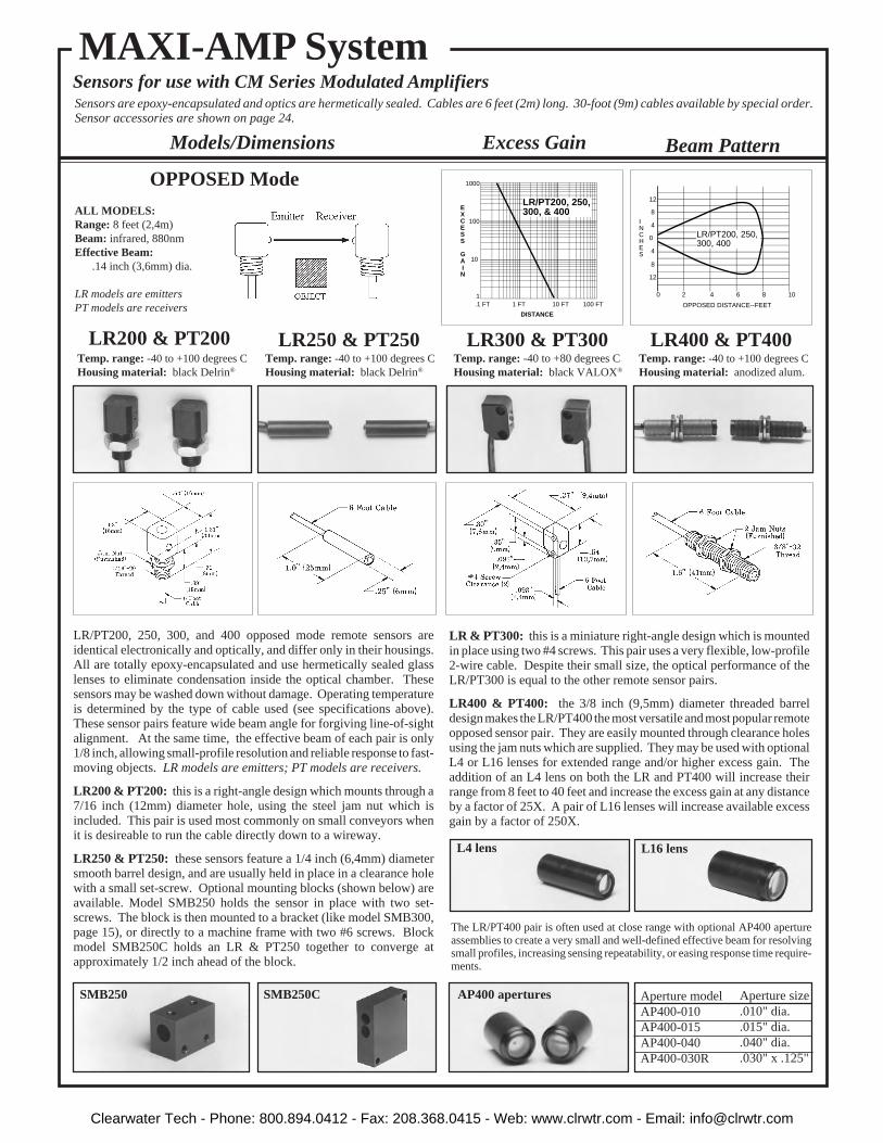
Beam Pattern
LR/PT200, 250, 300, and 400 opposed mode remote sensors areidentical electronically and optically, and differ only in their housings.All are totally epoxy-encapsulated and use hermetically sealed glasslenses to eliminate condensation inside the optical chamber. Thesesensors may be washed down without damage. Operating temperatureis determined by the type of cable used (see specifications above).These sensor pairs feature wide beam angle for forgiving line-of-sightalignment. At the same time, the effective beam of each pair is only1/8 inch, allowing small-profile resolution and reliable response to fast-moving objects. LR models are emitters; PT models are receivers.
LR200 & PT200: this is a right-angle design which mounts through a7/16 inch (12mm) diameter hole, using the steel jam nut which isincluded. This pair is used most commonly on small conveyors whenit is desireable to run the cable directly down to a wireway.
LR250 & PT250: these sensors feature a 1/4 inch (6,4mm) diametersmooth barrel design, and are usually held in place in a clearance holewith a small set-screw. Optional mounting blocks (shown below) areavailable. Model SMB250 holds the sensor in place with two set-screws. The block is then mounted to a bracket (like model SMB300,page 15), or directly to a machine frame with two #6 screws. Blockmodel SMB250C holds an LR & PT250 together to converge atapproximately 1/2 inch ahead of the block.
SMB250 SMB250C
LR200 & PT200 LR250 & PT250 LR300 & PT300 LR400 & PT400Temp. range: -40 to +100 degrees CHousing material: black Delrin®
Temp. range: -40 to +100 degrees CHousing material: black Delrin®
Temp. range: -40 to +80 degrees CHousing material: black VALOX®
Temp. range: -40 to +100 degrees CHousing material: anodized alum.
AP400 apertures
OPPOSED Mode
L4 lens L16 lens
The LR/PT400 pair is often used at close range with optional AP400 apertureassemblies to create a very small and well-defined effective beam for resolvingsmall profiles, increasing sensing repeatability, or easing response time require-ments.
10
1
DISTANCE
100
1000
.1 FT 1 FT 10 FT 100 FT
EXCESS
GAINI
LR/PT200, 250, 300, & 400
20
0
INCHES
OPPOSED DISTANCE--FEET
4 6 8 10
4
8
12
4
8
12
LR/PT200, 250, 300, 400
MAXI-AMP System
LR & PT300: this is a miniature right-angle design which is mountedin place using two #4 screws. This pair uses a very flexible, low-profile2-wire cable. Despite their small size, the optical performance of theLR/PT300 is equal to the other remote sensor pairs.
LR400 & PT400: the 3/8 inch (9,5mm) diameter threaded barreldesign makes the LR/PT400 the most versatile and most popular remoteopposed sensor pair. They are easily mounted through clearance holesusing the jam nuts which are supplied. They may be used with optionalL4 or L16 lenses for extended range and/or higher excess gain. Theaddition of an L4 lens on both the LR and PT400 will increase theirrange from 8 feet to 40 feet and increase the excess gain at any distanceby a factor of 25X. A pair of L16 lenses will increase available excessgain by a factor of 250X.
ALL MODELS:Range: 8 feet (2,4m)Beam: infrared, 880nmEffective Beam: .14 inch (3,6mm) dia.
LR models are emittersPT models are receivers
Sensors for use with CM Series Modulated AmplifiersSensors are epoxy-encapsulated and optics are hermetically sealed. Cables are 6 feet (2m) long. 30-foot (9m) cables available by special order.Sensor accessories are shown on page 24.
Aperture size.010" dia..015" dia..040" dia..030" x .125"
Aperture modelAP400-010AP400-015AP400-040AP400-030R
Excess GainModels/Dimensions
13Clearwater Tech - Phone: 800.894.0412 - Fax: 208.368.0415 - Web: www.clrwtr.com - Email: [email protected]

NOTE: for complete information on retro-reflective materials, see Banner catalog.
Range: 15 feet (4,5m) with BRT-3retroreflectorTemp. range: -40 to +80 degrees CHousing material: blue anodizedaluminum
Sensors are epoxy-encapsulated. Cables are 6 feet (2m) long. 30-foot (9m) cables available by special order.Sensor accessories are shown on page 24.
Sensors for use with CM Series Modulated Amplifiers
Models/Dimensions Excess Gain
forgiving for reflectively sensing transparent or translucent materials or forsensing objects with irregular surfaces (e.g.- webs with "flutter"). The optics aresuch that even small threads or wires .005" (0,1mm) or greater in diameter may bedetected when they pass within .25" (6mm) of the sensor's plastic lens. Due to itswide response pattern, the LP400WB should not be used for precise positioningcontrol, nor should it be mounted with its lens recessed into a hole.
"WB" in this model number designates "wide beam". The LP400WB is aninfrared divergent mode (wide angle diffuse mode) sensor which is particularly
100
0
INCHES
30 40 50
6
OPPOSED DISTANCE --FEET
12
18
6
12
18
20
SP300EL/RL
40
0
INCHES
8 12 15 18
2
DISTANCE TO REFLECTOR--FEET
4
6
2
4
6
with BRT-3 reflector
SP300L
10
INCHES
2 3 4 5
.5
DISTANCE TO 90% WHITE TEST CARD--INCHES
1.0
1.5
.5
1.0
1.5
LP400WB
0
10
1
DISTANCE
100
1000
.1 FT 1 FT 10 FT 100 FT
EXCESS
GAINI
SP300EL/RL
10
1
DISTANCE
100
1000
.1 FT 1 FT 10 FT 100 FT
withBRT-T tape
withBRT-1 target
withBRT-3 target
SP300LEXCESS
GAINI
100
10
1.1 IN 1 IN 10 IN 100 IN
1000
LP400WBRange based on 90% reflectancewhite test card
DISTANCE
EXCESS
GAINI
SP300L
SP300EL & SP300RL
MAXI-AMP System
RETROREFLECTIVEMode
DIVERGENTMode
Range: 50 feet (15m)Effective Beam: .5 inch (13mm) dia.Temp. range: -40 to +100 degrees CHousing material: anodized aluminum
Long RangeOPPOSED Mode
LP400WBRange: 3 inches (76mm)Temp. range: -40 to +80 degrees CHousing material: blue anodizedaluminum
Beam Pattern
Model SP300L is a remote retroreflective sensor with the same rugged designas the SP300EL/RL, described above. Its useable range is from 6 inches to 15feet (0,2 to 4,5m) using the model BRT-3 retroreflector.
Emitter-receiver pair SP300EL/RL are extremely rugged and are totally encap-sulated in anodized aluminum housings. The threaded hub at the cable exitallows for the use of flexible armored cable or protective PVC tubing with theaddition of compression gland model CF7-16 (page 24). This pair uses
14
collimating lenses to increase range. These sensors should also be used at shortranges for their high excess gain or to avoid optical "crosstalk" in situations whichrequire several pairs to be mounted adjacent to one another.
If the object that is to break the beam has a shiny surface, then the SP300L and itsretroreflector should be mounted so that the beam is at an angle of 10 degrees ormore to that surface in order to eliminate false signals which are caused by proxing.
Clearwater Tech - Phone: 800.894.0412 - Fax: 208.368.0415 - Web: www.clrwtr.com - Email: [email protected]

SP1000V CONVERGENT ModeRange: focus at 3.8 inches (96mm)Temp. range: -40 to +80 degrees CHousing material: black anodizedaluminum
SMB300UNIVERSAL MOUNTINGBRACKET forSP300 Sensors
SP300D: the SP300D is the diffuse mode version of the SP300L with thesame rugged aluminum housing and totally encapsulated construction. Theglass lenses are hermetically sealed, which eliminates any possibility ofcondensation inside the lenses and allows operation in adverse environ-ments like steam washdown and high vibration. The SP300D may bemounted by its through-holes or with the SMB300 bracket, as shown below.
SP320D: model SP320D is identical to the SP300D, except for its housing.The 320 is a miniature plastic package, designed to fit into very tightlocations. It mounts using two #4 (3mm) screws. The SP320D and theSP300D are excellent for nearly any presence sensing application.
SP300DRange: 12 inches (30cm)Temp. range: -40 to +80 degrees CHousing material: green anodizedaluminum
SP320D DIFFUSEModeRange: 12 inches (30cm)
Temp. range: -40 to +80 degrees CHousing material: black VALOX®
Models/Dimensions
Sensors are epoxy-encapsulated. Cables are 6 feet (2m) long. 30-foot (9m) cables available by special order.Sensor accessories are shown on page 24.
Sensors for use with CM Series Modulated amplifiers
Excess Gain
MAXI-AMP System
Beam Pattern
Accessory bracket model SMB300 is designed for 2-axis universal mount-ing of sensor models SP300EL, SP300RL, SP300L, and SP300D. Thesesensors are affixed to the SMB300 with two #6 (3,5mm) screws. Thebracket, in turn, mounts with two #10 (5mm) screws.
In addition, as indicated by the dimension drawing, the SMB300 has aclearance slot for mounting LR400, PT400, and LP400WB barrel sensors.LR & PT200 sensors may be mounted with the SMB300, using its 7/16-20threaded hole and steel jam nut, which is supplied with the sensors. LR250and PT250 sensors may be used with the SMB300 when the SMB250 blockis used (see page 13). Also, two SMB250 blocks may be attached to theSMB300 bracket and angled to mechanically converge an LR & PT250sensor pair.
The SP1000V is a convergent mode sensor that produces a very small 0.1inch (2,5mm) diameter sensing image at a point exactly 3.8 inches (96mm)from its glass lenses. As the excess gain curve illustrates, the SP1000V hasa very sharp drop-off of gain beyond the focus point. This feature makes itan excellent choice for detecting a small part which is only a fraction of aninch in front of another surface, such as parts on a conveyor (viewed fromabove). It is also ideal for fill level detection and for precise positioningcontrol, in lieu of opposed sensing.
10
1
DISTANCE
100
1000
.1 IN 1 IN 10 IN 100 IN
SP300D, SP320DEXCESS
GAINI
10
1
DISTANCE
100
1000
.1 IN 1 IN 10 IN 100 IN
SP1000VEXCESS
GAINI
30
0
INCHES
6 9 12 15
.2
DISTANCE TO 90% WHITE TEST CARD--INCHES
.4
.6
.2
.4
.6
SP300D, 320D
10
0
INCHES
2 3 5 4
.030
.060
.090
.090
.060
.030
DISTANCE TO 90% WHITE TEST CARD--INCHES
SP1000V
Clearwater Tech - Phone: 800.894.0412 - Fax: 208.368.0415 - Web: www.clrwtr.com - Email: [email protected]
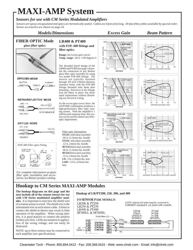
FIBER OPTIC Mode glass fiber optics
Range: see excess gain curvesTemp. range: -40 to +100 degrees C
Fiber optic information:IT13S: individual assembly.06 in. (1,5mm) dia. bundleIT23S: individual assembly.12 in. (3mm) dia. bundleBT13S:bifurcated assembly.06 in. (1,5mm) dia. bundleBT23S:bifurcated assembly.12 in. (3mm) dia. bundleL9: .5 in. (12mm) dia. lensL16F: 1.0 in. (25mm) dia.lens
Models/Dimensions
Sensors are epoxy-encapsulated and optics are hermetically sealed. Cables are 6 feet (2m) long. 30-foot (9m) cables available by special order.Sensor accessories are shown on page 24.
FOF-400 Fiber optic Fitting
Hookup of LR/PT200, 250, 300, and 400
60
0
INCHES
30
1
2
3
1
2
3
2412 18OPPOSED DISTANCE--INCHES
Opposed mode
w/IT13S fibers
w/IT23S fibers
LR/PT400
150
0
INCHES
OPPOSED DISTANCE--FEET
30 45 75
8
16
24
8
16
24
60
Opposed mode
IT23S fibers andL16F lenses
LR/PT400
IT23S fibers andL9 lenses
50
0
INCHES
25
3
6
9
3
6
9
2010 15
w/L9 lens
w/L16F lens
DISTANCE TO REFLECTOR--FEET
Retroreflective mode,with BRT-3 reflector andBT13S fiber
LR/PT400
10
0
INCHES
5 4 2 3DISTANCE TO 90% WHITE TEST CARD--INCHES
Diffuse mode
w/BT13S fibers
w/BT23S fibers0.2
0.4
0.6
0.6
0.4
0.2
LR/PT400
10
1
DISTANCE
100
1000
.1 IN 1 IN 10 IN 100 IN
Diffuse mode -- range based on 90% reflectance white test card
with BP13Sfibers
with BT23Sfibers
EXCESS
GAINI
LR/PT400
Beam PatternExcess Gain
10
1
DISTANCE
100
1000
.1 IN 1 IN 10 IN 100 IN
with IT23Sfibers
with IT13Sfibers
Opposed mode,no lenses
EXCESS
GAINI
LR/PT400
10
1
DISTANCE
100
1000
.1 FT 1 FT 10 FT 100 FT
Retroreflective mode, with BT13S fibers
with L16F lensand BRT-3 reflector
with L9 lensand BRT-3 reflector
EXCESS
GAINI
LR/PT400
10
1
DISTANCE
100
1000
.1 FT 1 FT 10 FT 100 FT
Opposed mode, with IT23S fibers
with L16F lenses
with L9 lenses
EXCESS
GAINI
LR/PT400
MAXI-AMP SystemSensors for use with CM Series Modulated Amplifiers
16
LR400 & PT400with FOF-400 fittings andfiber optics
For complete information on glassfiber optic assemblies and acces-sories, see Banner product catalog.
Hookup to CM Series MAXI-AMP ModulesThe hookup diagrams on this page and thenext include all of the remote sensors for usewith CM Series modulated amplifier mod-ules. It is important to note how the shield wireof a remote sensor is wired. The shield wire is theuninsulated wire in each sensor cable. Failure toconnect the shield as shown may result in falseoperation of the amplifier. When wiring emit-ters, it is good practice to connect the positive(white) wire first. LEDs are sensitive to applica-tion of the wrong voltage, and can easily bedestroyed.
NOTE: up to three sensors may be connected toeach amplifier (see specifications).
The threaded barrel design of theLR400 and PT400 (see page 14) per-mit the connection of any Bannerglass fiber optic assembly by usingtwo model FOF-400 fittings. Thesensors are typically mountedthrough 3/8 inch (10mm) diameterclearance holes, with the FOF-400fittings threaded onto them aftermounting. Setscrews in the fittingslock the fibers in place, but allowrapid replacement without disturb-ing any electrical wiring.
As the excess gain curves show, theLR/PT400 combination produces ahigh-performance fiber optic sens-ing system. With the amplifier's 1millisecond response time, this sys-tem can be used for almost any fiber-optic requirement.
Clearwater Tech - Phone: 800.894.0412 - Fax: 208.368.0415 - Web: www.clrwtr.com - Email: [email protected]

Sensor Hookup Diagrams for CM Series MAXI-AMP Modules
NOTE REGARDING CABLE SPLICING:When splicing additional cable length to modulated remote sensors,it is important to use a separate shielded cable for emitter andreceiver wires. Combining emitter and receiver wires together inthe same cable (even if the cable is shielded) will result in directcoupling of the emitter signal to the receiver leads. This is called"cable crosstalk", and will not allow full amplifier sensitivity settingwithout an amplifier "lock on" situation, which appears as a continu-ous LIGHT condition. Banner offers extension cable for remotesensors which, if used for cable splicing, will minimize the chancesfor cable crosstalk (see page 24).
The AUXILIARY terminal (#9) of CM3 models offers alogic-level NPN (current sinking) output which may be usedas a fast-response solid-state inhibit signal to the AUXIL-IARY input of MAXI-AMP CM5 modules. This output mayalso serve as an input to any B Series, Plug Logic, or CLSeries module. In addition, this output may interface toother dc devices or circuits like counters, rate meters, orprogrammable logic controllers. Switching capacity is20mA at 12V dc.
The example here shows the use of LR & PT400 sensors anda CM3 module to provide inspection information, with theSP300D functioning as a product sensor. Typically, theCM5 module would be programmed for the ONE-SHOT orDELAYED ONE-SHOT logic function. If the LR & PT400"sees" an acceptable condition when the SP300D senses theleading (or trailing) edge of a product, the CM3 will inhibita reject pulse from occuring.
External 10 to 30V dc devices such as self-contained sensorsmay be connected between terminals #3 (+) and #1 (-) of anyCM series MAXI-AMP module. Terminal #3 offers 40mAmaximum. This is sufficient to power most Banner self-contained dc sensors.
As the example at the right illustrates, the current sinkingoutput of a self-contained sensor powered by the MAXI-AMP may be used as the input to the AUXILIARY terminalof a CM5 module.
CM3Model
CM5Model
CM5Model
17
Logic Level NPN Output (CM3 models)
Power for External Devices
Hookup of SP320D
Hookup of LR300 and PT300 Hookup of SP300D, SP300L, LP400WB,and SP1000V
Clearwater Tech - Phone: 800.894.0412 - Fax: 208.368.0415 - Web: www.clrwtr.com - Email: [email protected]

MODEL OUTPUT LOGIC
CL3RA
CL3RB
CL5RA
CL5RB
SPDT electro-mechanicalrelay, plus NPNtransistor solid-state switch
SPDT electro-mechanical relay(5 amp contactrating)
ON/OFF
12timingfunctions
105 to 130V ac, or12 to 28V dc
210 to 250V ac, or12 to 28V dc
CL Series modules are available with a solid-state relay which replacesthe electromechanical relay. This is actually two SPST solid-statecontacts. One contact will switch ac loads, and is rated at 250V acmaximum and 3/4 amps maximum at 25 degrees C (derated to 1/2 ampat 50 degrees C). A solid-state contact is particularly helpful whenswitching inductive ac loads which can cause electrical "noise" andcontact damage when switched with a "hard" relay contact.
The other solid-state contact will switch dc loads of up to 30V dc andup to 50 milliamps. Both solid-state outputs are electrically isolatedfrom the MAXI-AMP power supply. Both outputs switch within the 1millisecond response time of the CL module circuitry. NOTE: ac loadsmay take up to 1/2 cycle (8.3 milliseconds) to turn "off".
Both outputs are normally open, but may be programmed for normallyclosed operation.
Except for the output configuration, the specifications for the modelslisted in the table at the right are exactly the same as for the standard CLSeries models.
Solid-state Output Option
SUPPLYVOLTAGE
210 to 250V ac, or12 to 28V dc
105 to 130V ac, or12 to 28V dc
MAXI-AMP ™ CL SeriesLogic-level Input Modules Recognized Certified
18
Banner CL Series MAXI-AMP™ modules are the perfect solution formany sensing/control applications where economy, versatility, de-pendability, and ruggedness are important. CL Series MAXI-AMPscombine power supply, timing logic (in CL5 models) and output relayin a single compact, cost-saving module. The integrated, stand-alonedesign saves both the expense of a separate control chassis and asubstantial amount of panel space. Several models are available, foreither 120V ac or 240V ac operation, and either with or without timinglogic (models are listed in table at above right). Alternatively, anymodel may be powered by 12 to 28V dc.
The well-defined electrical characteristics of CL Series MAXI-AMPmodules provide a wealth of application possibilities. The inputcircuit accepts signals from any Banner dc sensor with an NPN(current sinking) output; as well as from MAXI-AMP, MICRO-AMP,and Plug Logic modules. The input is compatible with almost anysensor or circuit which has an NPN transistor (current sinking) output.Additionally, inputs may be generated by limit switches, contactclosures, and optical couplers. A 50mA power supply is included forpowering 10 to 30V dc devices.
CL5 models offer a versatile multi-function timing logic circuit whichis programmable for twelve of the most popular and useful delay, one-shot, and latch functions (see page 6). The MAXI-AMP offers thechoice of either single or dual timing functions in the same module.Logic and timing may be easily reprogrammed as control require-ments change.
In order to allow accurate timing adjustments, each CL5 model hasthree time ranges to choose from. Timing adjustments are made viarugged 15-turn potentiometers. Circuitry is included to prevent anypossibility of false output on power-up.
An auxiliary input is available on CL5 models for interrogation orreset of the selected logic function by using an additional sensor orinput signal (see example, page 20). Page 6 describes the function ofthe auxiliary input for each logic mode.
The output circuit for all CL Series modules is an SPDT 5-amp electro-mechanical relay. A solid-state relay is offered as an option to theelectromechanical relay (see information below).
Additionally, CL3 models have an NPN transistor solid-state switch.This solid-state output may be used to take advantage of the amplifier'sfast 1-millisecond response. This output may be connected directly tothe primary or auxiliary input of other Banner logic modules, includ-ing CL5 modules, MICRO-AMP logic modules, and Plug Logicmodules. In addition, this output can interface to other dc devices orcircuits such as counters, rate meters, or programmable controllers.Switching capacity is 20mA at 12V dc. The output may be pro-grammed for either normally open or normally closed operation.
Like all MAXI-AMPs, the CL Series modules are designed bothelectrically and mechanically for solid dependability in industrialenvironments.
MODEL OUTPUT LOGIC
ON/OFF
12timingfunctions
105 to 130V ac, or12 to 28V dc
210 to 250V ac, or12 to 28V dc
CL3A
CL3B
CL5A
CL5B
SPST solid-statecontact forswitching ACloads up to 250Vac and up to 3/4amp, plus solid-state contact forswitching dcloads up to 30Vdc and up to50mA.
105 to 130V ac, or12 to 28V dc
210 to 250V ac, or12 to 28V dc
SUPPLYVOLTAGE
Clearwater Tech - Phone: 800.894.0412 - Fax: 208.368.0415 - Web: www.clrwtr.com - Email: [email protected]

NOTE #1: power is available at pins #3 (+) and #1 (-) for an external 10 to 30V dc device(see hookup example). Current available is 50mA at 120V ac (240V ac) line level; 40mAat 105V ac (210V ac) line level. Alternately, the module may be powered by 12 to 28Vdc at pins #3 (+) and #1 (-). Do not connect ac voltage if using external dc power.
NOTE #2: pulling pin #9 low (to Common) will inhibit the timing, or reset the latchof CL5 models. (See "Description of Logic Functions", page 6)NOTE #3: pin #9 of model CL3RA and CL3RB may be connected directly to theprimary or auxiliary input of MAXI-AMP model CL5 or to Banner Plug Logicmodules.
SUPPLY VOLTAGE: Models CL3RA, CL5RA: 105 to 130V ac,50/60Hz (4 VA), or 12 to 28V dc* at 60mA. Models CL3RB, CL5RB:210 to 250V ac, 50/60Hz (4 VA), or 12 to 28V dc at 60mA. *Do notconnect ac voltage if using external dc power.
OUTPUT CONFIGURATION: all models have SPDT electro-mechanical relay:CONTACT RATING: 250V ac max, 24V dc max, 5 amps max.(resistive load), 1/10 H.P. at 240V ac. Install transient suppressor(MOV) across contacts which switch inductive loads.CLOSURE TIME: 10 milliseconds max.RELEASE TIME: 10 milliseconds max.MAXIMUM SWITCHING SPEED: 20 operations/secondMECHANICAL LIFE: 20,000,000 operationsCL3 models also have a logic level current sinking NPN transistorswitch at pin #9. See schematic below and hookup info.
AMPLIFIER:RESPONSE SPEED: 1 millisecondINPUT CHARACTERISTICS: input is switched when the voltage atpin #2 is pulled below 1V dc or when less than 1K ohms is connectedbetween pins #2 and #1. When an inverting jumper is connectedbetween pins #10 and #11, input is switched when the voltage at pin #2rises above 4.5V dc or when the impedance between pins #2 and #1exceeds 15K ohms.HYSTERESIS: greater than .35 volts, less than 2 volts.
MULTIPLE SENSOR HOOKUP: any number of switched outputdevices may be connected in parallel to the input (see hookup example).
TIMERS (CL5 models only):TIME RANGES: LOW range - 10 to 150 milliseconds
MIDDLE range - 0.1 to 1.5 seconds HIGH range - 1 to 15 seconds
REPEATABILITY: +/-2% of set time over all extremes of supply voltage and temperature
ADJUSTMENTS: Miniature switches for setting of timing function,timing range, and output polarity (CL5 models). 15-turn clutchedpotentiometer for time setting (CL5 models).
MAXI-AMP CL Series SpecificationsINDICATOR LEDs: Red indicator LEDs for input and outputstatus.
CONSTRUCTION: Rugged NORYL® polyphenylene oxide(PPO® ) housing, 1.6" x 2.3" x 4". Standard round-pin 11-pole plugbase.
OPERATING TEMPERATURE: 0 to 50 degrees C (32 to 122degrees F).
Generalized Hookupmodels with electromechanical relay output
Functional Schematics
Dimension Drawing
CL5 Models CL3 Models
Clearwater Tech - Phone: 800.894.0412 - Fax: 208.368.0415 - Web: www.clrwtr.com - Email: [email protected]

SM912
WHITE
BROWN
BLUE
NOTE: Black wire is not used
CL3 or CL5model8
76
54
910
111
23
CL3 or CL5model8
76
54
910
111
23
MAXI-BEAM
4321
RPBT
PBT
1 2
3 4
MULTI-BEAM
CL3 or CL5model8
76
54
910
111
23
Sensor Hookup Diagrams for CL Series MAXI-AMP Modules
NOTE: the MAXI-AMP cannot power a MULTI-BEAM emitter and receiver pair.Use a separate power source for the emitter (e.g.- power block PBA-1, etc.)
CL5 model MAXI-AMPs have an auxiliary input at terminal #9which may be used for the interrogation or reset of the selectedlogic function. This is accomplished by a switch closure betweenpins #9 and #1 (Common). The auxiliary input may also beswitched by a DC device with an NPN transistor (current sinking)output. The effect of the auxiliary input is described for each logicfunction on page 6.
This example shows a typical inspection/rejection scheme whichuses a Banner MINI-BEAM as the inspection sensor. Typically,the CL5 module would be programmed for the ONE-SHOT orDELAYED ONE-SHOT logic function. If the SM312 "sees" anacceptable condition when the SE612 senses the leading (ortrailing) edge of the product, the SM312 will inhibit a reject pulsefrom occuring. Reject products will be ejected by the output pulse.
NOTE: the MAXI-AMP can supply 50mA for external 10 to 30Vdc devices. Carefully check the current draw of the devices to bepowered by the MAXI-AMP.
Use of Auxiliary Input (CL5 models)
NOTE: use power block model RPBT.
To MAXI-BEAM Sensors
To MINI-BEAM SM312 Series Sensors
To ECONO-BEAM SE612 Series Sensors
To MULTI-BEAM Sensors
To VALU-BEAM SM912 Series Sensors
NOTE: Black wire is not used
SM312
BROWN
BLUE
WHITE CL3 or CL5model8
76
54
910
111
23
NOTE: Black wire is not used SE612
WHITE
BROWN
BLUE
CL3 or CL5model8
76
54
910
111
23
+V dc @50ma
NOTE: Black wire is not used
+V dc(#3)
NOTE: Black wire is not used
White
DATA(Inspection)
GATE(Interrogate)
Brown
SE61R
Inhibit
BlueWhite
Brown
SM312
SE61E
Blue(#1)
Brown
Blue(#1)
+15V dc(#3)
CL3 or CL5model8
76
54
910
111
23
NOTE: use power block model PBTor PBT2.
20
To EZ-BEAM Sensors
NOTE: White wire is not used
This hookup is for DC NPN (currentsinking) models of S18 Series,Q25 Series, and other DC sensorsbearing the EZ-BEAM logo.
BROWN
BLUE
BLACK CL3 or CL5model8
76
54
910
111
23
Clearwater Tech - Phone: 800.894.0412 - Fax: 208.368.0415 - Web: www.clrwtr.com - Email: [email protected]

LIGHT OPERATE
DARK OPERATE
DARK OPERATE
If any receiver "sees"light
When all receivers"see" dark
OUTPUT OCCURS(AFTER DELAY, IFANY)
If any receiver "sees"dark
When all receivers"see" light
NO
NO
YES
(NOTE: see page 6 fordescription of logic functions)
YES
LIGHT OPERATE
INVERTING JUMPERInstalled Between ModuleTerminals #10 and #11
SENSOR PROGRAM:Light or Dark Operate LOGIC DESCRIPTION
The diagram shows switch locations,and the table summarizes the programswitch positions.
Hookup of Multiple Self-contained SensorsAny number of self-contained dc sensors may be wired to-gether in parallel to a single CL Series MAXI-AMP module tocreate almost any multiple-sensor logic configuration. Powerfor the sensors may be obtained from MAXI-AMP 400mApower supply CP12 (shown below) or from 1-amp modelPS120-15. The table at the right describes how the four mostfrequently used multiple-sensor logic configurations may becreated.
MINI-BEAM SM312 Series and VALU-BEAM SM912 Se-ries sensors have a switch on the back of their housings whichis used to program the sensors for LIGHT or DARK operate.MAXI-BEAM sensors are set for LIGHT or DARK operateusing the programming ring. MULTI-BEAM sensors areprogrammed for LIGHT or DARK operate with the logicmodule jumper wire. OMNI-BEAMs are programmed by aswitch in the sensor block.
For ON/OFF sensor operation, light operate is equated tonormally open output, and dark operate is defined asnormally closed. EZ-BEAM sensors have both a normallyopen and a normally closed output. Selection of either outputdetermines the LIGHT/DARK operate mode. ECONO-BEAMsensors are not programmable and must be ordered for LIGHTOPERATE (standard models) or DARK OPERATE (modelsuffix "NC").
The addition of a jumper wire between MAXI-AMP terminals#10 and #11 changes the input response from a low-going toa high-going signal. This feature, combined with the selectionof LIGHT or DARK operate at the sensor, allows "AND" logicwith parallel sensor connections.
Timing Logic Programming (CL5 models)Settings illustrated below are factory settings. Factory settings are "underlined" in the table.
A group of ten switches located on one side of the module is used to select the timing logic forCL5 models.
Switches #1 through #7 are used to select the logic function. Switch #8 programs the outputfor either NORMALLY OPEN or NORMALLY CLOSED operation. Switches #9 and #10program the time range(s). There are three ranges: 10 to 150 milliseconds, 0.1 to 1.5 seconds,and 1 to 15 seconds. The programmed range will be the same for both functions of a dual timingmode (ON & OFF DELAY, DELAYED ONE-SHOT, and REPEAT CYCLE). However,DELAY and HOLD times are independently adjustable within the selected range.
21
LIGHT "OR"
DARK "AND"
DARK "OR"
LIGHT "AND"
105-130V ac
Brown+V dc
Brown+V dc
Blue(#1)
White
+V dc
Brown
105-130V AC
Blue(#1)
SM31R/RL
White
SM31R/RL SM31E/EL Blue(#1)
Brown+V dc
Blue SM31R/RL
White
CL3 or CL5model
87
65
4 CP12power supply87
65
4
910
111
23
SM31E/EL Blue(#1)
Brown+V dc
SM31E/EL Blue(#1)
Brown+V dc
910
111
23
ON
OFFON
ON ON ON OFF ON OFF ON
PROGRAMMINGTIMING LOGIC
#1 #2 #3 #4 #5 #6 #7 #8 #9 #10
10
ON
OFF
1
2
3
4
5
6
7
8
9
SWITCH SWITCH SWITCH SWITCH
ON
ON
ONON
OFF
OFF
OFF
SWITCH SWITCH SWITCH SWITCH SWITCH SWITCH
On/Off
On Delay
Off Delay
On and Off Delay
One-shot
Delayed One-shot
Limit
Repeat Cycle
AC Latch
DC Latch
Delay and Latch
Limit and Latch
ON ON OFF ON OFF ON
OFF OFFOFF OFF ON
ONOFFOFF OFF ON OFF ON
OFF OFFOFF OFF OFF
ON ON ONOFFOFF OFFOFF
OFF ON ON OFF ON
OFF ON ON OFF
ON
ONONON
ONON OFF ONONON
ON ON OFF OFF ONONON
ON ON OFF OFF OFF ONON
N/C Output
N/O Output
.15 Sec. Max. Time
1.5 Sec. Max. Time
15 Sec. Max. Time
OFF
OFF OFF
OFF ON
ON OFF ON OFF ON OFF ON
Clearwater Tech - Phone: 800.894.0412 - Fax: 208.368.0415 - Web: www.clrwtr.com - Email: [email protected]
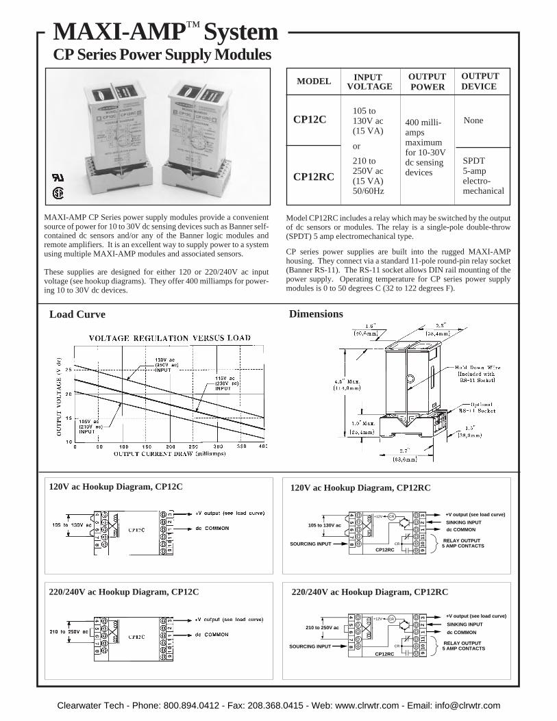
87
65
4
910
111
23 +V output (see load curve)
dc COMMON
RELAY OUTPUT 5 AMP CONTACTS
210 to 250V ac
CP12RC
SOURCING INPUT
SINKING INPUT
CR
+12V CR
SINKING INPUT
87
65
4
910
111
23
CR
+V output (see load curve)
dc COMMON
RELAY OUTPUT 5 AMP CONTACTS
105 to 130V ac
CP12RCSOURCING INPUT
+12V CR
MODEL
CP12C
CP12RC
None
MAXI-AMP CP Series power supply modules provide a convenientsource of power for 10 to 30V dc sensing devices such as Banner self-contained dc sensors and/or any of the Banner logic modules andremote amplifiers. It is an excellent way to supply power to a systemusing multiple MAXI-AMP modules and associated sensors.
These supplies are designed for either 120 or 220/240V ac inputvoltage (see hookup diagrams). They offer 400 milliamps for power-ing 10 to 30V dc devices.
Model CP12RC includes a relay which may be switched by the outputof dc sensors or modules. The relay is a single-pole double-throw(SPDT) 5 amp electromechanical type.
CP series power supplies are built into the rugged MAXI-AMPhousing. They connect via a standard 11-pole round-pin relay socket(Banner RS-11). The RS-11 socket allows DIN rail mounting of thepower supply. Operating temperature for CP series power supplymodules is 0 to 50 degrees C (32 to 122 degrees F).
400 milli-ampsmaximumfor 10-30Vdc sensingdevices
220/240V ac Hookup Diagram, CP12C
120V ac Hookup Diagram, CP12C
220/240V ac Hookup Diagram, CP12RC
120V ac Hookup Diagram, CP12RC
105 to130V ac(15 VA)
or
210 to250V ac(15 VA)50/60Hz
SPDT5-ampelectro-mechanical
INPUTVOLTAGE
OUTPUTDEVICE
OUTPUT POWER
DimensionsLoad Curve
MAXI-AMP ™ SystemCP Series Power Supply Modules
Clearwater Tech - Phone: 800.894.0412 - Fax: 208.368.0415 - Web: www.clrwtr.com - Email: [email protected]

Model RS-11 Socket
Track model DIN-35-70 accomodates one RS-11 socket. Model DIN-35-105holds two sockets. Model DIN-35-140 holds up to three sockets. The RS-11socket is designed to snap (or slide) directly into the 35mm DIN track.
35mm DIN Rail Track Model BENC-4 Enclosure
The RS-11 is supplied with a coding ring and pin (see diagram at right). This allows a MAXI-AMP to bekeyed to fit only its own 11-pin socket. The pin is installed in one of the eleven slots in the RS-11, and thenotch in the ring is aligned to slip over the pin. When the MAXI-AMP is removed from the RS-11, thecoding ring stays with the MAXI-AMP base, while the coding pin remains in the socket.
Model RS-11 is an eleven-pole round-pin screwterminal relay socket which is used to make elec-trical connections to any MAXI-AMP module.The socket provides in-line wire clamp screwterminals which will accept from one #24 AWGup to two #14 wires at each pin. The RS-11 is ULrecognized (file #E92191) and CSA approved (file#LR38486). It may be mounted directly to a panelplate or via standard 35mm DIN-rail track (seebelow). A hold-down wire is supplied with eachRS-11 socket (see Dimension Diagram on page22).
Model BENC-4 is a NEMA-4 rated corrosion-resistant enclosure for a MAXI-AMP module or other control device. It is supplied with a DIN-35-70 track foreasy mounting of one RS-11 socket. For mounting two sockets, use DIN-35-105.
MAXI-AMP SystemMounting and Accessories
23
Accessories for MAXI-AMP Modules
After the panel cutout has been completed and de-burred, slide the MAXI-AMP through the cutout andplace one clip assembly into the rectangular depressionon each of the two narrow sides of the housing. Orientclips as shown, and alternately tighten the screws forequal pressure against the inside of the panel wall. Donot overtighten the screws. Attach the optional EC11-6 extension cable (described below) to the MAXI-AMPand route the opposite end of the cable to the RS-11 (orequivalent) socket.
Model EC11-6 extension cable is 6 feet (2m) long.Clips for panel wall mounting of the MAXI-AMP areincluded with the cable.
Panel Wall Mounting of MAXI-AMP Module
Clearwater Tech - Phone: 800.894.0412 - Fax: 208.368.0415 - Web: www.clrwtr.com - Email: [email protected]
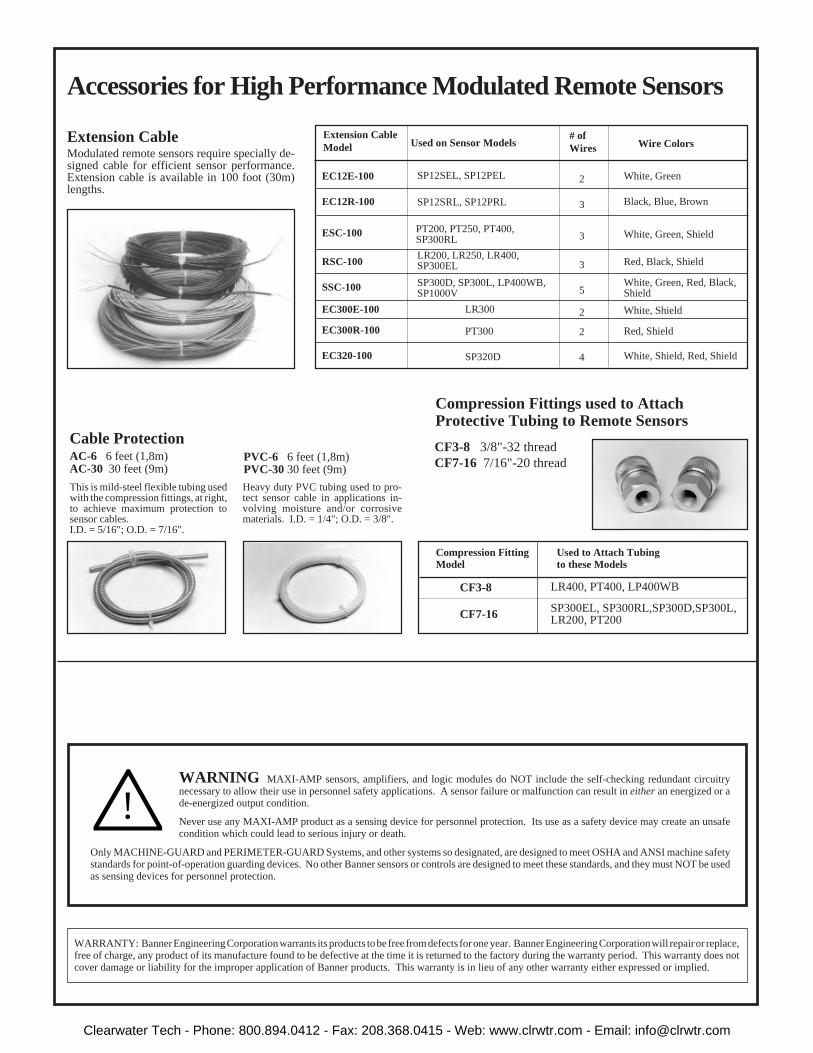
WARNING MAXI-AMP sensors, amplifiers, and logic modules do NOT include the self-checking redundant circuitrynecessary to allow their use in personnel safety applications. A sensor failure or malfunction can result in either an energized or ade-energized output condition.
Never use any MAXI-AMP product as a sensing device for personnel protection. Its use as a safety device may create an unsafecondition which could lead to serious injury or death.
Only MACHINE-GUARD and PERIMETER-GUARD Systems, and other systems so designated, are designed to meet OSHA and ANSI machine safetystandards for point-of-operation guarding devices. No other Banner sensors or controls are designed to meet these standards, and they must NOT be usedas sensing devices for personnel protection.
!
WARRANTY: Banner Engineering Corporation warrants its products to be free from defects for one year. Banner Engineering Corporation will repair or replace,free of charge, any product of its manufacture found to be defective at the time it is returned to the factory during the warranty period. This warranty does notcover damage or liability for the improper application of Banner products. This warranty is in lieu of any other warranty either expressed or implied.
LR400, PT400, LP400WB
This is mild-steel flexible tubing usedwith the compression fittings, at right,to achieve maximum protection tosensor cables.I.D. = 5/16"; O.D. = 7/16".
Used to Attach Tubingto these Models
Compression FittingModel
SP300EL, SP300RL,SP300D,SP300L,LR200, PT200
CF3-8
CF7-16
Used on Sensor Models# ofWires Wire Colors
Extension CableModel
EC12E-100
EC12R-100
ESC-100
RSC-100
SSC-100
EC300E-100
EC300R-100
EC320-100
PT200, PT250, PT400,SP300RL
SP12SEL, SP12PEL
SP12SRL, SP12PRL
LR200, LR250, LR400,SP300EL
SP300D, SP300L, LP400WB,SP1000V
LR300
PT300
SP320D
2
3
3
3
5
2
2
4
White, Green
Black, Blue, Brown
White, Green, Shield
Red, Black, Shield
White, Green, Red, Black,Shield
White, Shield
Red, Shield
White, Shield, Red, Shield
Extension CableModulated remote sensors require specially de-signed cable for efficient sensor performance.Extension cable is available in 100 foot (30m)lengths.
Cable ProtectionAC-6 6 feet (1,8m)AC-30 30 feet (9m)
PVC-6 6 feet (1,8m)PVC-30 30 feet (9m)
Heavy duty PVC tubing used to pro-tect sensor cable in applications in-volving moisture and/or corrosivematerials. I.D. = 1/4"; O.D. = 3/8".
Accessories for High Performance Modulated Remote Sensors
CF3-8 3/8"-32 thread CF7-16 7/16"-20 thread
Compression Fittings used to AttachProtective Tubing to Remote Sensors
Clearwater Tech - Phone: 800.894.0412 - Fax: 208.368.0415 - Web: www.clrwtr.com - Email: [email protected]

SUPPLY VOLTAGE: 105 to 130 or 210 to 250V ac, 50/60 Hz (8VA)
OUTPUT CONFIGURATION:SPDT electromechanical relay:Contact rating: 250V ac maximum, 24V dc maximum, 5 amps maximum(resistive load), 1/10 HP at 240V ac. Install transient suppressor (MOV)across contacts which switch inductive loads.Closure time: 10 milliseconds maximum.Release time: 10 milliseconds maximum.Maximum switching speed: 20 operations/second.Mechanical life: 20,000,000 operationsSolid-state dc relay: SPST optically-coupled transistor;30V dc maximum, 20mA maximum.
EMITTER POWER: +24V dc at 25 mA maximum available atmodule pin #3.
INPUTS:Trip point for output "OFF": ≤10 milliampsTrip point for output "ON": ≥20 milliampsTrip point range for input overload indication: 30mA ≤ I ≤ 80mA.
INDICATOR LEDs:OUTPUT "ON" and INPUT overload/short.
OPERATING TEMPERATURE: 0 to 50°C (32 to 122°F).
CONSTRUCTION: rugged NORYL® polyphenylene oxide (PPO®)housing, 1.6" x 2.3" x 4". Standard round-pin 11-pole base.Use RS-11 socket or equivalent.
SPECIFICATIONS
Current TripPoint Module
••
•
••
Self-contained current sensing amplifier
Works with intrinsically safe barrier to provide power toBanner SMI Series intrinsically safe DC sensor(s); convertsinput signal from the sensor to a contact closure
Powers a single sensor or both the emitter and receiver of anopposed mode pair
Powered by 105-130 or 210-250V ac (50/60Hz)
Two output devices: SPDT 5 amp electromechanical relayand opto-isolated transistor for logic level dc switching
DIMENSION DRAWING FUNCTIONAL SCHEMATIC
Printed in USA P/N 36611
The Banner MAXI-AMP model CI3RC2 (p/n 36606) is a self-contained module which converts the current output signal of anSMI Series intrinsically safe sensor to a trip point switch.
Banner SMI Series intrinsically safe sensors carry Factory MutualResearch's rating for use in hazardous areas. Sensors are wired tomodel CI3RC2 using the two-wire hookup through an intrinsi-cally safe barrier. Refer to the hookups, page 2. The SMI Seriessensor sinks ≤10 milliamps in the "OFF" state and ≥20 milliampsin the "ON" state. The CI3RC2 module senses this current changeand switches internal relays that may be easily wired to most loadsand/or additional control circuitry.
Model CI3RC2 is powered by either 105-130 or 210-250V ac. Itsupplies dc power to operate a single sensor or both the emitterand receiver of one SMI Series opposed mode sensor pair. Thesensor's input to the CI3RC2 is protected against short circuits.
MAXI-AMP™ CI3RC2for SMI Series intrinsically safe sensors
Built-in circuit diagnostics indicate an input overload by flashingan LED status light.
The MAXI-AMP CI3RC2 module has two isolated outputswitches. There is a 5-amp rated SPDT electromechanical relay,and a solid-state transistor switch which may be used for logic-level interfaces.
Banner also offers the CI3RC2 Current Trip Point Module as partof a kit. See page 2 for further information. The CI3RC2 may beused with the following Banner Intrinsically Safe sensors: SMI30Series, SMI912 Series.
CI3RC2 module (left) shown with RS-11 socket and DINrail; also SMI30 Series emitter/receiver pair and intrinsicsafety barrier.
Clearwater Tech - Phone: 800.894.0412 - Fax: 208.368.0415 - Web: www.clrwtr.com - Email: [email protected]

HOOKUP DIAGRAM B: Hookup ofSMI Series Intrinsically Safe Emitter/receiver
pair to CI3RC2
Banner Engineering Corp., 9714 10th Ave. No., Minneapolis, MN 55441 Telephone (612) 544-3164 FAX (Applications): (612) 544-3573
GENERALIZED HOOKUP, CI3RC2
SMI Series sensors are certified intrinsically safe ONLY when used withcertified energy-limiting intrinsically-safe barriers. Banner does notitself manufacture intrinsically-safe barriers. Barriers may, however, bepurchased from Banner. Kit CI2BK-1 includes one each of the follow-ing: single channel barrier, CI3RC2 amplifier, RS-11 socket, DIN railmount, and a 70 mm DIN rail for mounting the socket. Kit CI2BK-2provides a dual channel barrier in place of the single channel barrier.Barriers are available separately (below right).
An SMI Series sensor is wired through a barrier using the 2-wire hookup.In the 2-wire hookup configuration, the sensor acts as a current sink,drawing less than 10mA in the OFF state and more than 20mA in the ONstate. Model CI3RC2 senses this current change and switches internalrelays. The SPDT electromechanical relay in the CI3RC2 can switch a
load which draws up to 5 amps (see specifications). The SPST solid-staterelay can switch a dc load of up to 30V dc, max.; 20mA, max.
SMI Series emitter-only units also use the 2-wire hookup through a barrier(see hookup diagram "B"). Emitter power (24V dc, 25 mA maximum) isobtained at pin #3. This is sufficient to power one emitter.
The user of this equipment is responsible for the proper installation andmaintenance of the equipment, and must conform with certificationrequirements relating to barriers and to maximum allowable capacitanceand inductance of field wiring. If you have questions about these require-ments, Banner applications engineers can refer you to the proper authority.
!WARNING This photoelectric sensing product does NOTinclude the self-checking redundant circuitry necessary to allowits use in personnel safety applications. A failure or malfunctioncan result in either an energized or a de-energized output
condition.
Never use this product as a sensing device for personnel protection. Its useas a safety device may create an unsafe condition which could lead to seriousinjury or death.
Only MACHINE-GUARD and PERIMETER-GUARD Systems, and othersystems so designated, are designed to meet OSHA and ANSI machine safetystandards for point-of-operation guarding devices. No other Banner sensorsor controls are designed to meet these standards, and they must NOT be usedas sensing devices for personnel protection.
WARRANTY: Banner Engineering Corporation warrants its products to be free from defects for a period of one year. Banner Engineering Corporation will repairor replace, free of charge, any product of its manufacture found to be defective at the time it is returned to the factory during the warranty period. This warrantydoes not cover damage or liability for the improper application of Banner products. This warranty is in lieu of any other warranty either expressed or implied.
HOOKUP DIAGRAM A: Hookup ofSMI Series Intrinsically Safe Sensor to CI3RC2(except emitter - see below)
1110
COMMON
INPUT RELAY OUTPUT 5 AMP CONTACTS
87
65
4
91
23
105 to 130V ac
210 to 250V ac
ACSUPPLY
CI3RC2OPTO-COUPLER OUTPUT: 20mA max.
HAZARDOUS AREA
SAFE AREA
G
EARTH GROUND(less than 1Ω)
BLUE
BROWN
BLACK
BUSBAR
≤10 MA. (OFF STATE)≥20 MA. (ON STATE)
IN
BOTTOM VIEW OF CABLE CONNECTOR ON SENSOR(colors shown are for matingcable model MBCC-312)
INPUT:
I.S.
+
- -
+
V
BARRIER
1
2 3
OUT
G
SMI SeriesSensor Kit CI2BK-1 (p/n 36860),
one each:Single-channel barrierCI3RC2 amplifierRS-11 socketDIN rail mount70 mm DIN rail
Kit CI2BK-2 (p/n 36605),one each:
Dual-channel barrierCI3RC2 amplifierRS-11 socketDIN rail mount70 mm DIN rail
Barriers are availableseparately:
Single channel barrier:CIB-1 (p/n 27030)
Dual channel barrier:CI2B-1 (p/n 36865)
Kits for use withIntrinsically Safe
Sensors
1
2 3
1110
COMMON
INPUT RELAY OUTPUT 5 AMP CONTACTS
87
65
4
91
23
105 to 130V ac
210 to 250V ac
ACSUPPLY
CI3RC2OPTO-COUPLER OUTPUT: 20mA max.
HAZARDOUS AREA
SAFE AREA
EARTH GROUND(less than 1Ω)
BLUE
BROWN
BLACK
BUSBAR
≤10 MA. (OFF STATE)≥20 MA. (ON STATE)
BROWN
BLUE
BOTTOM VIEW OF CABLE CONNECTOR ON SENSOR(colors shown are for matingcable model MBCC-312)
INPUT:
1
2 3
G
AUX.
OUT
SMI SeriesReceiver
SMI SeriesEmitter
IN
IN OUT+
I.S.
+
-
+
+
Dual Barrier
-
4
5
6
7
8
3
2
1
11
10
9
AUX.INPUT
INPUT
COMMON
OUTPUT30V dc max.20 mA max.
110V ac
220V ac
ACSUPPLY
8 VA50/60 Hz
OUTPUT RELAY250V ac max. 24V dc max. 5A max.
NOTE: Two single channel barriersmay be used in lieu of one dualchannel barrier.
Clearwater Tech - Phone: 800.894.0412 - Fax: 208.368.0415 - Web: www.clrwtr.com - Email: [email protected]