basic concepts on systems of systems
TRANSCRIPT

Basic Concepts on Systems of Systems
Andrea Ceccarelli1(&), Andrea Bondavalli1, Bernhard Froemel2,Oliver Hoeftberger2, and Hermann Kopetz2
1 Department of Mathematics and Informatics,University of Florence, Florence, Italy
{andrea.ceccarelli,andrea.bondavalli}@unifi.it2 Institute of Computer Engineering,
Vienna University of Technology, Vienna, Austria{froemel,oliver}@vmars.tuwien.ac.at,
1 Introduction
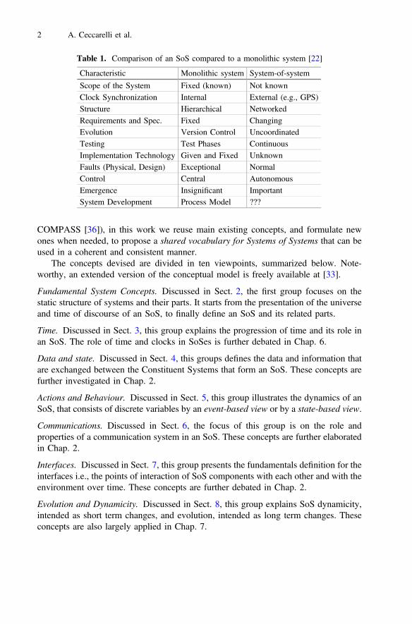
A System of System (SoS) stems from the integration of existing systems (legacysystems), normally operated by different organizations, and new systems that have beendesigned to take advantage of this integration. Many of the established assumptions inclassical system design, such as e.g., the scope of the system is known, that the designphase of a system is terminated by an acceptance test or that faults are exceptionalevents, are not justified in an SoS environment. This is well represented by Table 1.
In this chapter we present the fundamental concepts for Systems of Systemsengineering established within the AMADEOS1 project, with the objective ofproposing a shared System of Systems vocabulary and define an implicit theory aboutthe SoS domain.
The overarching concern of our work is to target the reduction of the cognitivecomplexity needed to comprehend the behaviour of a SoS by the application ofappropriate simplification strategies [29]. In fact, the considerable cognitive effortneeded to understand the operation of a large SoS is the main cause for the substantialengineering (and monetary) effort required to design and maintain many of today’sSystems of Systems.
Our position is that the first important step of achieving simplicity is the devel-opment of an understandable set of concepts that describes the SoS domain. In fact, ifthe language used to talk about a domain contains terms with clearly defined meaningsthat are shared by a wide part of the domain community, then the communication ofideas among experts is simplified. Consequently, starting from a detailed analysis of theexisting concepts for the SoS domain (e.g., from the projects DANSE [35], DSoS [7],
This work has been partially supported by the FP7-610535-AMADEOS project.
1 FP7-ICT-2013-10-610535 AMADEOS: Architecture for Multi-criticality Agile Dependable Evolu-tionary Open System-of-Systems, http://amadeos-project.eu/.
© The Author(s) 2016A. Bondavalli et al. (Eds.): Cyber-Physical Systems of Systems, LNCS 10099, pp. 1–39, 2016.DOI: 10.1007/978-3-319-47590-5_1
COMPASS [36]), in this work we reuse main existing concepts, and formulate newones when needed, to propose a shared vocabulary for Systems of Systems that can beused in a coherent and consistent manner.
The concepts devised are divided in ten viewpoints, summarized below. Note-worthy, an extended version of the conceptual model is freely available at [33].
Fundamental System Concepts. Discussed in Sect. 2, the first group focuses on thestatic structure of systems and their parts. It starts from the presentation of the universeand time of discourse of an SoS, to finally define an SoS and its related parts.
Time. Discussed in Sect. 3, this group explains the progression of time and its role inan SoS. The role of time and clocks in SoSes is further debated in Chap. 6.
Data and state. Discussed in Sect. 4, this groups defines the data and information thatare exchanged between the Constituent Systems that form an SoS. These concepts arefurther investigated in Chap. 2.
Actions and Behaviour. Discussed in Sect. 5, this group illustrates the dynamics of anSoS, that consists of discrete variables by an event-based view or by a state-based view.
Communications. Discussed in Sect. 6, the focus of this group is on the role andproperties of a communication system in an SoS. These concepts are further elaboratedin Chap. 2.
Interfaces. Discussed in Sect. 7, this group presents the fundamentals definition for theinterfaces i.e., the points of interaction of SoS components with each other and with theenvironment over time. These concepts are further debated in Chap. 2.
Evolution and Dynamicity. Discussed in Sect. 8, this group explains SoS dynamicity,intended as short term changes, and evolution, intended as long term changes. Theseconcepts are also largely applied in Chap. 7.
Table 1. Comparison of an SoS compared to a monolithic system [22]
Characteristic Monolithic system System-of-system
Scope of the System Fixed (known) Not knownClock Synchronization Internal External (e.g., GPS)Structure Hierarchical NetworkedRequirements and Spec. Fixed ChangingEvolution Version Control UncoordinatedTesting Test Phases ContinuousImplementation Technology Given and Fixed UnknownFaults (Physical, Design) Exceptional NormalControl Central AutonomousEmergence Insignificant ImportantSystem Development Process Model ???
2 A. Ceccarelli et al.
System design and tool. Discussed in Sect. 9, this group sets the foundational conceptsto define design methodologies to engineer SoSes.
Dependability and Security. Discussed in Sect. 10, this group presents dependabilityand security concepts, in compliance with the taxonomies presented in [1, 3, 4].
Emergence. The phenomenon of emergence in Cyber-Physical Systems of Systemsand its main concepts are largely discussed in Chap. 3. Consequently, this group ofconcepts is only briefly introduced in this Chapter. The definition of emergencereported in Chap. 3 states that “a phenomenon of a whole at the macro-level isemergent if and only if it is of a new kind with respect to the non-relational phenomenaof any of its proper parts at the micro level”. Emergent phenomena can be of a differentnature either beneficial or detrimental and either expected or unexpected. Managingemergence is essential to avoid undesired, possibly unexpected situations generatedfrom CSs interactions and to realize desired emergent phenomena being usually thehigher goal of an SoS [30]. For example, system safety has been acknowledged as anemerging property [31], because its meaning at the SoS level does not have the samemeaning for the individual CS, and obviously it cannot be expressed just as the sum ofthe individual parts. Additionally, to further strengthen on the relevance of emergencein an SoS, we remark that it is acknowledged that the SoS may be exposed to newsecurity threats when novel phenomena arise [32, 34].
2 Fundamental System Concepts
2.1 Universe and Time of Discourse
We start by delineating the universe and time of discourse of an SoS.
Universe of Discourse (UoD): The Universe of Discourse comprises the set of entitiesand the relations among the entities that are of interest when modeling the selectedview of the world.
The word domain is often used as synonym to the notion Universe of Discourse.
Interval of Discourse (IoD): The Interval of Discourse specifies the time interval thatis of interest when dealing with the selected view of the world.
In order to structure the UoD during the IoD, we must identify objects that have adistinct and self-contained existence.
Entity: Something that exists as a distinct and self-contained unit.
We distinguish between two very different kinds of entities, things and constructs.
Thing: A physical entity that has an identifiable existence in the physical world.
Basic Concepts on Systems of Systems 3

Referring to the Three World Model of Popper [8] there is another class of entities,we call them constructs that have no physical existence on their own but are productsof the human mind.
Construct: A non-physical entity, a product of the human mind, such as an idea.
2.2 Systems
We use the definition of the term system introduced in the EU Project DSOS(Dependable System-of-systems IST-1999-11585 [9]):
System: An entity that is capable of interacting with its environment and may besensitive to the progression of time.
By ‘sensitive to the progression of time’ we mean the system may react differently,at different points in time, to the same pattern of input activity, and this difference isdue to the progression of time. A simple example is a time-controlled heating system,where the temperature set-point depends on the current time [9]. The role of humans ina system is discussed at length below in this section.
Environment of a System: The entities and their actions in the UoD that are not part ofa system but have the capability to interact with the system.
In classical system engineering, the first step in the analysis of a system is theestablishment of an exact boundary between the system under investigation and itsenvironment.
System Boundary: A dividing line between two systems or between a system and itsenvironment.
In SoS Engineering, such an approach can be problematic, because in many SoSthe system boundary is dynamic. Consider, e.g., a car-to-car SoS that consists of aplurality of cars cruising in an area. Where is the boundary of such an SoS? A goodconcept should be stable, i.e., its important properties, such as size, should remain fairlyconstant during the IoD. The boundary of the car-to-car SoS does not satisfy thisrequirement and is thus a poor concept. Our analysis of many other existing SoSs, e.g.,the worldwide ATM system or a smart grid system came to a similar conclusion: it ishardly possible to define a stable boundary of an SoS [22, 29].
In the above example of a car-to-car SoS each individual car in the system (con-sisting of the mechanics of the car, the control system within the car and the driver) canbe considered as an autonomous system that tries to achieve its given objective withoutany control by another system.
Autonomous System: A system that can provide its services without guidance byanother system.
4 A. Ceccarelli et al.

Before starting with the detailed design of a large system an overall blueprint thatestablishes the framework of the evolving artifact should be developed.
System Architecture: The blueprint of a design that establishes the overall structure,the major building blocks and the interactions among these major building blocks andthe environment.
Every organization that develops a system follows a set of explicit or implicit rulesand conventions, e.g., naming conventions, representation of data (e.g., endianness ofdata), protocols etc. when designing the system. This set of explicit or implicit rulesand conventions is called the architectural style.
Many of the existing legacy systems have been designed in the context of a singleorganization that follows its often ill-documented idiosyncratic architectural style. Forexample, undocumented implicit assumptions about the attributes of data can lead tomismatches when data is sent from one subsystem to another subsystem in an SoS.
Monolithic System: A system is called monolithic if distinguishable services are notclearly separated in the implementation but are interwoven.
Many systems are not monolithic wholes without any internal structure, but arecomposed of interrelated parts, each of the latter being in turn hierarchic in structureuntil we reach some lowest level of elementary subsystem [11], p. 184.
Subsystem: A subordinate system that is a part of an encompassing system.
We call the subsystems of a System of Systems (SoS) Constituent Systems (CSs).
Constituent System (CS): An autonomous subsystem of an SoS, consisting of computersystems and possibly of controlled objects and/or human role players that interact toprovide a given service.
The decomposition of a system into subsystems can be carried out until the internalstructure of a subsystem is of no further interest. The systems that form the lowest levelof a considered hierarchy are called components.
Some systems can be decomposed without loss into well-understood parts, so thatthe functions at the system level can be derived from the functions of the parts [25].
Cyber-Physical System (CPS): A system consisting of a computer system (the cybersystem), a controlled object (a physical system) and possibly of interacting humans.
An interacting human can be a prime mover or role player.
Prime mover: A human that interacts with the system according to his/her own goal.
An example for a prime mover could be a legitimate user or a malicious user thatuses the system for his/her own advantage. A human who is a prime mover can beconsidered to be a constituent system (CS).
Basic Concepts on Systems of Systems 5
Role player: A human that acts according to a given script during the execution of asystem and could be replaced in principle by a cyber-physical system.
A CPS is composed not only of the computer system, i.e., the cyber system, butalso of a controlled object and possibly a human role player.
Entourage of a CPS: The entourage is composed of those entities of a CPS (e.g., therole playing human, controlled object) that are external to the cyber system of the CPSbut are considered an integral part of the CPS.
2.3 System-of-Systems
We decided to select the following definition of Jamishidi as the starting point of ourwork [10].
System-of-Systems (SoS): An SoS is an integration of a finite number of constituentsystems (CS) which are independent and operable, and which are networked togetherfor a period of time to achieve a certain higher goal.
We consider the phrase that are networked together for a period of time animportant part of this definition, since it denotes that a static scope of an SoS may notexist and the boundary between an SoS and its environment can be dynamic.
Dahmann and Baldwin have introduced the following four categories of SoSs [11]:
Directed SoS: An SoS with a central managed purpose and central ownership of allCSs. An example would be the set of control systems in an unmanned rocket.
Acknowledged SoS: Independent ownership of the CSs, but cooperative agreementsamong the owners to an aligned purpose.
Collaborative SoS: Voluntary interactions of independent CSs to achieve a goal that isbeneficial to the individual CS.
Virtual SoS: Lack of central purpose and central alignment.
While a directed SoS, e.g., the CSs in an automobile that are under strict centralmanagement and ownership of a car company, comes close to a homogenous system,the other extreme, a virtual CS, lacks the elements of homogeneity and is formed byheterogeneous subsystems belonging to very different organizations.
We call an interface of a CS where the services of a CS are offered to other CSs aRelied Upon Interface (RUI). It is ‘“relied upon’’ with respect to the SoS, since theservice of the SoS as a whole relies on the services provided by the respective CSsacross the RUIs.
Relied upon Interface (RUI): An interface of a CS where the services of the CS areoffered to other CSs.
6 A. Ceccarelli et al.
In addition to a Relied upon Message Interface (RUMI) where messages containinginformation are exchanged among the CSs, a Relied upon Physical Interface (RUPI)where things or energy are exchanged among the CSs can exist.
Relied upon Message Interface (RUMI): A message interface where the services of aCS are offered to the other CSs of an SoS.
Relied upon Physical Interface (RUPI): A physical interface where things or energyare exchanged among the CSs of an SoS.
Relied upon Service (RUS): (Part of) a Constituent System (CS) service that is offeredat the Relied Upon Interface (RUI) of a service providing CS under a Service LevelAgreement (SLA).
There may be other interfaces to systems external to a CS which we investigate inSect. 6, together with the issues of information exchange and interface specification.
3 Time
The focus of the previous Section was on the static structure of systems and their parts.In this Section we start being concerned with change. The concept of change dependson the progression of time that is one of the core topics that is investigated inAMADEOS. In an SoS a global notion of time is required in order to
• Enable the interpretation of timestamps in the different CSs.• Limit the validity of real-time control data.• Synchronize input and output actions across nodes.• Provide conflict-free resource allocation.• Perform prompt error detection.• Strengthen security protocols.
We base our model of time on Newtonian physics and consider time as an inde-pendent variable that progresses on a dense time-line from the past into the future. For adeep discussion on the issues of time we refer to the excellent book by Withrow, TheNatural Philosophy of Time [12] that considers also the revision to the Newtonianmodel by the theory of relativity. From the perspective of an SoS the relativistic modelof time does not bring any new insights above those of the Newtonian model of time.
3.1 Basics on Time
Time: A continuous measurable physical quantity in which events occur in a sequenceproceeding from the past to the present to the future.
This definition of time, which denotes physical time, has been adapted fromDictionary.com and uses a number of fundamental concepts that cannot be definedwithout circularity.
Basic Concepts on Systems of Systems 7

Timeline: A dense line denoting the independent progression of time from the past tothe future.
The directed time-line is often called the arrow of time. According to Newton, timeprogresses in dense (infinitesimal) fractions along the arrow of time from the past to thefuture.
Instant: A cut of the timeline.
Event: A happening at an instant.
An event is a happening that reports about some change of state at an instant.
Signal: An event that is used to convey information typically by prearrangementbetween the parties concerned.
Instants are totally ordered, while events are only partially ordered. More than oneevent can happen at the same instant.
Temporal order: The temporal order of events is the order of events on the timeline.
Causal order: A causal order among a set of events is an order that reflects the cause-effect relationships among the events.
Temporal order and causal order are related, but not identical. Temporal order of acause event followed by an effect event is a necessary prerequisite of causal order, butcausal order is more than temporal order [2], p. 53.
Interval: A section of the timeline between two instants.
While an interval denotes a section of the timeline between two instants, theduration informs about the length only, but not about the position of such a section.
Duration: The length of an interval.
The length of an interval can only be measured if a standard for the duration isavailable. The physical SI second is such an international standard (the InternationalSystem of Units is abbreviated by SI).
Second: An internationally standardized time measurement unit where the duration ofa second is defined as 9 192 631 770 periods of oscillation of a specified transition ofthe Cesium 133 atom.
The physical second is the same in all three important universal time standards,UTC, TAI and GPS time. UTC (Universal Time Coordinated) is an astronomical timestandard that is aligned with the rotation of the earth. Since the rotational speed of theearth is not constant, it has been decided to base the SI second on atomic processesestablishing the International Atomic Time TAI (Temps Atomique International). OnJanuary 1, 1958 at 00:00:00 TAI and UTC had the same value. The TAI standard ischronoscopic and maintained as the weighted average of the time kept by over 200
8 A. Ceccarelli et al.
atomic clocks in over 50 national laboratories. TAI is distributed world-wide by thesatellite navigation system GPS (Global Positioning System).
Offset of events: The offset of two events denotes the duration between two events andthe position of the second event with respect to the first event on the timeline.
The position of an instant on a standardized timeline can only be specified if astarting point, the origin, for measuring the progression of time (in seconds) has beenestablished.
Epoch: An instant on the timeline chosen as the origin for time-measurement.
GPS represents the progression of TAI time in weeks and full seconds within aweek. The week count is restarted every 1024 weeks, i.e., after 19.6 years. The Epochof the GPS signal started at 00:00:19 TAI on January 6, 1980 and again, after 1024weeks at 00:00:19 TAI on August 22, 1999.
Cycle: A temporal sequence of significant events that, upon completion, arrives at afinal state that is related to the initial state, from which the temporal sequence ofsignificant events can be started again.
An example for a cycle is the rotation of a crankshaft in an automotive engine.Although the duration of the cycle changes, the sequence of the significant eventsduring a cycle is always the same.
Period: A cycle marked by a constant duration between the related states at the startand the end of the cycle.
Periodic Systems are of utmost relevance in control applications
Periodic System: A system where the temporal behaviour is structured into a sequenceof periods.
Periodicity is not mandatory, but often assumed as it leads to simpler algorithmsand more stable and secure systems [14], pp. 19–4. Note that the difference betweencycle and period is the constant duration of the period during the IoD.
3.2 Clocks
Time is measured with clocks. In the cyber-domain, digital clocks are used.
Clock: A (digital) clock is an autonomous system that consists of an oscillator and aregister. Whenever the oscillator completes a period, an event is generated thatincrements the register.
Oscillators and digital clocks are closely related. When looking at an oscillator, theform of the wave over the full cycle is of importance. When looking at a clock, only thedistance between the events that denote the completion of cycles of the oscillator is ofimportance.
Basic Concepts on Systems of Systems 9

Nominal Frequency: The desired frequency of an oscillator [24].
Frequency drift: A systematic undesired change in frequency of an oscillator over time[24].
Frequency drift is due to ageing plus changes in the environment and other factorsexternal to the oscillator.
Frequency offset: The frequency difference between a frequency value and the refer-ence frequency value [24].
Stability: The stability of a clock is a measure that denotes the constancy of theoscillator frequency during the IoD.
The state of the register of a clock is often called the state of clock. The state of aclock remains constant during a complete period of the oscillator.
Wander: The long-term phase variations of the significant instants of a timing signalfrom their ideal position on the time-line (where long-term implies here that thesevariation of frequency are less than 10 Hz). (see also jitter) [24].
Jitter: The short-term phase variations of the significant instants of a timing signalfrom their ideal position on the time-line (where long-term implies here that thesevariation of frequency are greater than or equal to 10 Hz). (see also wander) [24].
The term timing signal can refer to a signal of a clock or of any other periodicevent. There exist other clocks, e.g., a sun dial, which is not digital in nature. The timeresolution of every digital clock is limited by the duration of the period of the oscillator.
Tick: The event that increments the register is called the tick of the clock.
Granularity/Granule of a clock: The duration between two successive ticks of a clockis called the granularity of the clock or a granule of time.
The granularity of a clock can only be measured if another clock with a finergranularity is available. We introduce a reference clock as a working hypothesis formeasuring the instant of occurrence of an event of interest (such as, e.g., a clock tick)and make the following three hypothetical assumptions: (i) the reference clock has sucha small granularity, e.g., a femto second (10−15 s), that digitalization errors can beneglected as second order effects, (ii) the reference clock can observe every event ofinterest without any delay and (iii) the state of the reference clock is always in perfectagreement with TAI time.
Reference clock: A hypothetical clock of a granularity smaller than any duration ofinterest and whose state is in agreement with TAI.
Coordinated Clock: A clock synchronized within stated limits to a reference clock thatis spatially separated [24].
10 A. Ceccarelli et al.
Every good (fault-free) free-running clock has an individual granularity that candeviate from the specified nominal granularity by an amount that is contained in thespecification document of the physical clock under investigation.
Drift: The drift of a physical clock is a quality measure describing the frequency ratiobetween the physical clock and the reference clock.
Since the drift of a good clock is a number close to 1, it is conducive to introduce adrift rate by
Drift Rate ¼ Drift�1j j
Typical clocks have a drift rate of 10−4 to 10−8. There exists no perfect clock with adrift rate of 0. The drift rate of a good clock will always stay in the interval contained inthe specification document of the clock. If the drift rate of a clock leaves this specifiedinterval, we say that the clock has failed.
Timestamp (of an event): The timestamp of an event is the state of a selected clock atthe instant of event occurrence.
Note that a timestamp is always associated with a selected clock. If we use thereference clock for time-stamping, we call the time-stamp absolute.
Absolute Timestamp: An absolute timestamp of an event is the timestamp of this eventthat is generated by the reference clock.
If events are occurring close to each other, closer than the granularity of a digitalclock, then an existing temporal order of the events cannot be established on the basisof the timestamps of the events.
If two events are timestamped by two different clocks, the temporal order of theevents can be established on the basis of their timestamps only if the two clocks aresynchronized.
Clock Ensemble: A collection of clocks, not necessary in the same physical location,operated together in a coordinated way either for mutual control of their individualproperties or to maximize the performance (time accuracy and frequency stability) andavailability of a time-scale derived from the ensemble [24].
Clock synchronization establishes a global notion of time in a clock ensemble.A global notion of time is required in an SoS if the timestamps generated in one CSmust be interpreted in another CS. Global time is an abstraction of physical time in adistributed computer system. It is approximated by a properly selected subset of theticks of each synchronized local clock of an ensemble. A selected tick of a local clock iscalled a tick of the global time. For more information on the global notion of time, see[2], pp. 58–64.
Basic Concepts on Systems of Systems 11
Precision: The precision of an ensemble of synchronized clocks denotes the maximumoffset of respective ticks of the global time of any two clocks of the ensemble over theIoD. The precision is expressed in the number of ticks of the reference clock.
The precision of an ensemble of clocks is determined by the quality of the oscil-lators, by the frequency of synchronization, by the type of synchronization algorithmand by the jitter of the synchronization messages. Once the precision of the ensemblehas been established, the granularity of the global time follows by applying the rea-sonableness condition.
Reasonableness Condition: The reasonableness condition of clock synchronizationstates that the granularity of the global time must be larger than the precision of theensemble of clocks.
We distinguish between two types of clock synchronization, internal clock syn-chronization and external clock synchronization.
Internal Clock Synchronization: The process of mutual synchronization of anensemble of clocks in order to establish a global time with a bounded precision.
There are a number of different internal synchronization algorithms, both non-faulttolerant or fault-tolerant, published in the literature (see e.g., [13], and many others).These algorithms require the cooperation of all involved clocks.
External Clock Synchronization: The synchronization of a clock with an external timebase such as GPS.
Primary Clock: A clock whose rate corresponds to the adopted definition of the sec-ond. The primary clock achieves its specified accuracy independently of calibration.
The term master clock is often used synonymously to the term primary clock. If theclocks of an ensemble are externally synchronized, they are also internally synchro-nized with a precision of |2A|, where A is the accuracy.
Accuracy: The accuracy of a clock denotes the maximum offset of a given clock fromthe external time reference during the IoD, measured by the reference clock.
The external time reference can be a primary clock or the GPS time.
3.3 Time in an SoS
In a recent report from the GAO to the US Congress [15] it is noted that a global notionof time is required in nearly all infrastructure SoSs, such as telecommunication,transportation, energy, etc. In an SoS, external clock synchronization is the preferredalternative to establish a global time, since the scope of an SoS is often ill defined and itis not possible to identify a priori all CSs that must be involved in the (internal) clock
12 A. Ceccarelli et al.

synchronization. A CS that does not share the global time established by a subset of theCSs cannot interpret the timestamps that are produced by this subset.
The preferred means of clock synchronization in an SoS is the external synchro-nization of the local clocks of the CSs with the standardized time signal distributedworldwide by satellite navigation systems, such as GPS, Galileo or GLONASS.The GPS system, consisting at least of 24 active satellites transmit periodic time signalsworldwide that are derived from satellite-local atomic clocks and seldom differ fromeach other by more than 20 ns [14]. A GPS receiver decodes the signals and calculates,based on the offset among the signals, the position and time at the location of the GPSreceiver. The accuracy of the GPS time is better than 100 ns. The periodic time signal,generated by a GPS receiver, can be used to discipline a quartz oscillator.
GPSDO (Global Positioning System Disciplined Oscillator): The GPSDO synchro-nizes its time signals with the information received from a GPS receiver.
With a well-synchronized GPSDO a drift rate in the order 10−10 can be achieved.
Holdover: The duration during which the local clock can maintain the requiredprecision of the time without any input from the GPS.
According to [16], p. 62 a good GPSDO has deviated from GPS time by less than100 μsec during the loss of GPS input of one week. As long as the GPS is operatingand its input is available, a GPSDO can provide an accuracy of the global time of betterthan 100 nsec. If there is the requirement that, the free running global time must notdeviate by more than 1 μsec, a holdover of up to one hour is achievable using a goodGPSDO.
The measurement of the position of an event on the timeline or of the durationbetween two events by a digital global time must take account of two types ofunavoidable errors, the synchronization error caused by the finite precision of theglobal time and the digitalization error caused by the discrete time base. If the rea-sonableness condition is respected, the sum of these errors will be less than 2g, whereg is the granularity of the global time. It follows that the true duration between twoevents dtrue lies in the following interval around the observed value dobs.
ðdobs � 2gÞ \dtrue\ðdobs þ 2gÞ
The duration between events that are temporally ordered can be smaller than thegranularity of a single clock. This situation is even worse if two different globallysynchronized clocks observe the two different events. It is therefore impossible toestablish the true temporal order of events in case the events are closer together than2g. This impossibility result can give rise to inconsistencies about the perceivedtemporal order of two events in distributed system.
These inconsistencies can be avoided, if a minimum distance between events ismaintained, such that the temporal order of the events, derived from the timestamps ofthe events that have been generated by different clocks of a system with properlysynchronized clocks is always the same.
Basic Concepts on Systems of Systems 13

Sparse Time: A time-base in a distributed computer system where the physical time ispartitioned into an infinite sequence of active and passive intervals.
The active intervals can be enumerated by the sequence of natural numbers and thisnumber can be assigned as the timestamp of an event occurring in an active interval. Inorder to establish consistency all events that occur in the same active interval of asparse time are considered to have occurred simultaneously. This procedure establishesconsistency at the price of faithfulness, since the temporal order of events that are closertogether than the distance between sparse events is lost.
Sparse Events: Events that occur in the active interval of the sparse time.
Events that are in the SoC of a computer system with access to a global time, e.g.,the start of sending a message, can be delayed until the next active interval and thus canbe forced to be sparse events.
Non-Sparse Events: Events that occur in the passive interval of the sparse time.
Events that are outside the SoC of the computer system and are in the SoC of theenvironment cannot be forced to occur in the active intervals of the sparse time base,and can therefore be non-sparse events.
If all observers of a non-sparse event agree, by the execution of an agreementprotocol, that the observed non-sparse event should be moved to the same nearestactive interval of the sparse time base, then the consistency of these events can beestablished at the price of a further reduced faithfulness.
Time-aware SoS: A SoS is time-aware if its Constituent Systems (CSs) can use a globaltimebase in order to timely conduct output actions and consistently – within the wholeSoS – establish the temporal order of observed events.
4 Data and State
Systems-of-Systems (SoSs) come about by the transfer of information of one Con-stituent System (CS) to another CS. But what is information? How is informationrelated to data? After a thorough investigation of the literature about the fundamentalconcepts data and information it is concluded, that these terms are not well-defined inthe domain of information science-see also the paper by C. Zins who asked a number ofcomputer scientists about their meaning associated with the terms data-information-knowledge and published the divergent views reported to him in [16]. In this Sec-tion we will elaborate on the concepts of data and information along the lines ofreasoning expressed in [17].
4.1 Data and Information
Let us start by defining the fundamental concepts of data and information [17]:
14 A. Ceccarelli et al.

Data: A data item is an artefact, a pattern, created for a specified purpose.
In cyber space, data is represented by a bit-pattern. In order to arrive at the meaningof the bit pattern, i.e., the information expressed by the bit pattern, we need an ex-planation that tells us how to interpret the given bit pattern.
Information: A proposition about the state of or an action in the world.
A proposition can be about factual circumstances or plans, i.e., schemes for actionin the future. In any case, information belongs to the category of constructs, i.e.,non-physical entities in world three of Popper [8]. Sometimes the phrase semanticcontent is used as a synonym for information.
Explanation: The explanation of the data establishes the links between data andalready existing concepts in the mind of a human receiver or the rules for handling thedata by a machine.
Since only the combination of data and an associated explanation can conveyinformation, we form the new concept of an Itom that we consider the smallest unit thatcan carry information.
Itom: An Itom (Information Atom) is a tuple consisting of data and the associatedexplanation of the data.
The concept of an Itom is related to the concept of an infon introduced by Floridi[18]. However, the properties we assign to an Itom are different from the propertiesFloridi assigns to an infon. The concept of an Itom does not make any assumptionsabout the truthfulness of the semantic content, the information, in the Itom. We thuscan attribute factual information as true information (correspondence theory of truth[19]), misinformation (accidentally false) or disinformation (intentionally false), or justcall it information if we do not know yet if it is true or false. It is often the case thatonly some time after data has been acquired it can be decided whether the informationconveyed by the data is true or false (e.g., consider the case of a value error of asensor).
When data is intended for a human receiver then the explanation must describe thedata using concepts that are familiar to the intended human receiver. When data isintended for processing by a machine, the explanation consists of two parts, we callthem computer instructions and explanation of purpose [17].
The computer instructions tell the computer system how the data bit-string ispartitioned into syntactic chunks and how the syntactic chunks have to be stored,retrieved, and processed by the computer. This part of the explanation can thus beconsidered as a machine program for a (virtual) computer. Such a machine program isalso represented by a bit-string. We call the data bit-string object data and theinstruction bit-string that explains the object data, meta data.
A computer Itom thus contains digital object data and digital meta data. Therecursion stops when the meta data is a sequence of well-defined machine instructions
Basic Concepts on Systems of Systems 15
for the destined computer. In this case, the design of the computer serves as an ex-planation for the meaning of the data.
The second part of the explanation of an Itom, the explanation of purpose, isdirected to humans who are involved in the design and operation of the computersystem, since the notion of purpose is alien to a computer system. The explanation ofpurpose is part of the documentation of the cyber system and must be expressed in aform that is understandable to the human user/designer.
To facilitate the exchange of information among heterogeneous computer systemsin the Internet, markup languages, such as the Extensible Markup Language XML [20],that help to explain the meaning of data have been developed. Since in XML theexplanation is separated from the data, the explanation can be adopted to the context ofuse of the data. Markup languages provide a mechanism to support an explanation ofdata. In many situations the explanation of the data is taken implicitly from the context.
When data is moved from one CS to another CS of an SoS, the context maychange, implying that an explanation that is context-dependent changes as well. Takethe example of temperature expressed as a number. In one context (e.g., Europe) thenumber is interpreted as degrees Celsius, while in another context (e.g., the US) thenumber is interpreted as degrees Fahrenheit. If we do not change the number (the data)then the meaning of the Itom is changed when moving the data from one context toanother context. The neglected context sensitivity of data has caused accidents inSoSs [21].
An observation of a dynamic entity is only complete if the instant, the timestamp ofmaking the observation, is recorded as part of the explanation.
The timestamp of input data is determined by the termination instant of the sensingprocess.
No timestamp is needed in the explanation when the properties of the observedentity are static. In the context of our work, we are mostly interested in dynamicproperties of systems.
4.2 State
Many systems store information about their interactions with the environment (sincethe start of a system with a clean memory) and use this information to influence theirfuture behaviour.
State: The state of a system at a given instant is the totality of the information from thepast that can have an influence on the future behaviour of a system.
A state is thus a valued data structure that characterizes the condition of a system atan instant. The concept of state is meaningless without a concept of time, since thedistinction between past and future is only possible if the system is time-aware.
Stateless System: A system that does not contain state at a considered level ofabstraction.
Statefull System: A system that contains state at a considered level of abstraction.
16 A. Ceccarelli et al.

The variables that hold the stored state in a statefull system are called statevariables.
State Variable: A variable that holds information about the state.
State Space: The state space of a system is formed by the totality of all possible valuesof the state variables during the IoD.
Instantaneous State Space: The state space of a system is formed by the totality of allpossible values of the state variables at a given instant.
If we observe the progress of a system, we will recognize that the size of theinstantaneous state space grows or shrinks as time passes. The instantaneous state spacehas a relative minimum at the start and end of an atomic action.
The size of the instantaneous state space is important if we want to restart a systemafter a failure (e.g., a corruption of the state by a transient fault). We have to repair thecorrupted instantaneous state before we can reuse the system. Generally, the smaller theinstantaneous state space at the instant of reintegration, the easier it is to repair andrestart a system.
Most control systems are cyclic or even periodic systems.
Ground State: At a given level of abstraction, the ground state of a cyclic system is astate at an instant when the size of the instantaneous state space is at a minimumrelative to the sizes of the instantaneous state spaces at all other instants of the cycle.
We call the instant during the cycle of a cyclic system where the size of theinstantaneous state has a minimum the ground state instant.
Ground State Instant: The instant of the ground state in a cyclic system.
At the ground state instant all information of the past that is considered relevant forthe future behaviour should be contained in a declared ground state data structure. Atthe ground state instant no task may be active and all communication channels areflushed. Ground state instants are ideal for reintegrating components that have failed.
Declared Ground State: A declared data structure that contains the relevant groundstate of a given application at the ground state instant.
The declared ground state is essential for system recovery. The declared groundstate contains only of those ground state variables that are considered relevant by thedesigner for the future operation of the system in the given application. Other groundstate variables are considered non-relevant because they have only a minor influence onthe future operation of the system. The decision of whether an identified state variableis relevant or not relevant depends on a deep understanding of the dynamics of anapplication.
Basic Concepts on Systems of Systems 17
Concise State: The state of a system is considered concise if the size of the declaredground state is at most in the same order of magnitude as the size of the system’slargest input message.
Many control systems have a concise state. There are other systems, such as database systems that do not have a concise state—the size of the state of a data-basesystem can be Gigabytes.
In contrast to state variables that hold information about the state at an instant anevent variable holds information about a change at an instant.
Event Variable: A variable that holds information about some change of state at aninstant.
5 Actions and Behaviour
We can observe the dynamics of a system that consists of discrete variables by anevent-based view or by a state-based view.
In the event-based view we observe the state of relevant state variables at thebeginning of the observation and then record all events (i.e. changes of the statevariables) and the time of occurrence of the events in a trace. We can reconstruct thevalue of all state variables at any past instant of interest by the recorded trace. However,if the number of events that can happen is not bounded, the amount of data generatedby the event-based view cannot be bounded.
In the periodic state-based view (called sampling), we observe the values of rele-vant state variables at selected observation instants (the sampling points) and recordthese values of the state variables in a trace. The duration between two observationinstants puts a limit on the amount of data generated by the state-based view. However,the price for this limit is the loss of fidelity in the trace. Events that happen within aduration that is shorter than the duration between the equidistant observation instantsmay get lost.
Sampling: The observation of the value of relevant state variables at selected obser-vation instants.
Most control systems use sampling to acquire information about the controlledobject. The choice of the duration between two observation instants, called the sam-pling interval, is critical for acquiring a satisfying image of the controlled object. Thisissue is discussed extensively in the literature about control engineering [23].
5.1 Actions
In the following we introduce some concepts that allow us to describe the dynamics ofa computer system.
Action: The execution of a program by a computer or a protocol by a communicationsystem.
18 A. Ceccarelli et al.

An action is started at a specified instant by a start signal and terminates at aspecified instant with the production of an end signal.
Start signal: An event that causes the start of an action.
End signal: An event that is produced by the termination of an action.
Between the start signal and end signal an action is active.
Execution Time: The duration it takes to execute a specific action on a given computer.
The execution time depends on the performance of the available hardware and isalso data dependent.
Worst Case Execution Time (WCET): The worst-case data independent execution timerequired to execute an action on a given computer.
There are two possible sources for a start signal of an action.
Time-triggered (TT) Action: An action where the start signal is derived from theprogression of time.
An action can also be started by the completion of the previous action or by someother event (e.g., the push of a start button).
Event-triggered (ET) Action: An action where the start signal is derived from an eventother than the progression of time.
We distinguish also between computational actions and communication actions.
Computational Action: An action that is characterized by the execution of a programby a machine.
Communication Action: An action that is characterized by the execution of a com-munication protocol by a communication system.
In our model of an action we assume that at the start event an action reads inputdata and state. At the end event an action produces output data and a new state. Anaction reads input data if the input data is still available after the action. An actionconsumes input data if the input data record is unavailable after the consumption by anaction.
An action writes output data, if an old version of the output data is overwritten bythe output data generated by the action. An action produces output data if a new unit ofoutput data is generated by the action.
Input Action: An action that reads or consumes input data at an interface.
Output Action: An action that writes or produces output data at an interface.
Basic Concepts on Systems of Systems 19
We distinguish between actions that access the state of a system and those that donot.
Stateless Action: An action that produces output on the basis of input only and doesnot read, consume, write or produce state.
Statefull action: An action that reads, consumes, writes or produces state.
An action starts at the start signal and terminates by producing an end signal. In theinterval <start signal, end signal> an action is active. While an action is active, thenotion of state is undefined.
We can compose actions to form action sequences.
Action Sequence: A sequence of actions, where the end-signal of a preceding actionacts as the start signal of a following action.
An action sequence is often called a process.
Activity Interval: The interval between the start signal and the end signal of an actionor a sequence of related actions.
An action at a given level of abstraction, e.g., the execution of a program, can bedecomposed into sub-actions. The decomposition ends when the internal behaviour of asub-action is of no concern.
Atomic Action: An atomic action is an action that has the all-or-nothing property. Iteither completes and delivers the intended result or does not have any effect on itsenvironment.
Atomic actions are related to the notion of a component introduced above: neitherthe internals of components (from the point of view of structure) nor the internals of anatomic action (from the point of view of behaviour) are of interest.
Irrevocable Action: An action that cannot be undone.
An irrevocable action has a lasting effect on the environment of a system. Forexample, consider an output action that triggers an airbag in a car.
Idempotent Action: An action is idempotent if the effect of executing it more than oncehas the same effect as of executing it only once.
For example, the action move the door to 45° is idempotent, while the action movethe door by five degrees is not idempotent. Idempotent actions are of importance in theprocess of recovery after a failure.
We can combine computational action and communication actions to form atransaction.
Transaction: A related sequence of computational actions and communication actions.
Real-Time (RT) Transaction: A time-bounded transaction.
20 A. Ceccarelli et al.
In a control system the duration of the RT-transaction that starts with the obser-vation of the controlled object and terminates with the output of the result to anactuating device has an effect on the quality of control.
Transaction Activity Interval: The interval between the start signal and the end signalof a transaction.
5.2 Behaviour
The behaviour of a system-the observable traces of activity at the system interfaces-isof utmost interest to a user.
Function: A function is a mapping of input data to output data.
Behaviour: The timed sequence of the effects of input and output actions that can beobserved at an interface of a system.
The effect of a consuming input action is the consumption of the input data record,while the effect of a reading input action does not change the input data and thereforehas no observable effect. This is not true at the output side. Both, a writing outputaction and a producing output action have an observable effect.
Deterministic Behaviour: A system behaves deterministically if, given an initial stateat a defined instant and a set of future timed inputs, the future states, the values andinstants of all future outputs are entailed.
A system may exhibit an intended behaviour or it may demonstrate a behaviour thatis unintended (e.g., erroneous behaviour).
Service: The intended behaviour of a system.
The service specification must specify the intended behaviour of a system. In nonreal-time systems, the service specification focuses on the data aspect of the behaviour.In real-time systems the precise temporal specification of the service is an integral partof the specification.
Capability: Ability to perform a service or function.
6 Communication
It is the basic objective of a communication system to transport a message from asender to one or more receivers within a given duration and with a high dependability.By high dependability we mean that by the end of a specified time window the messageshould have arrived at the receivers with a high probability, the message is not cor-rupted, either by unintentional or intentional means, and that the security of the mes-sage (confidentiality, integrity, etc.) has not been compromised. In some environments
Basic Concepts on Systems of Systems 21

e.g., the Internet of Things (IoT), there are other constraints on the message transport,such as, e.g., minimal energy consumption.
In an SoS the communication among the CSs by the exchange of messages is thecore mechanism that realizes the integration of the CSs. It is imperative to elaborate onthe concepts related to the message exchange with great care.
Since communication requires that diverse senders and receivers agree on the rulesof the game, all involved partners must share these rules and their interpretation.
Communication Protocol: The set of rules that govern a communication action.
In the past fifty years, hundreds of different communication protocols that oftenonly differ in minor aspects, have been developed. Many of them are still in use inlegacy systems. This diversity of protocols hinders the realization of the economies ofscale by the semiconductor industry.
We distinguish between two classes of protocols: basic transport protocols andhigher-level protocols. The basic transport protocols are concerned with the transport ofdata from a sender to one or more receivers. The higher-level protocols build on thesebasic transport protocols to provide more sophisticated services.
6.1 Messages
Message: A data structure that is formed for the purpose of the timely exchange ofinformation among computer systems.
We have introduced the word timely in this definition to highlight that a messagecombines concerns of the value domain and of the temporal domain in a single unit.
In the temporal domain, two important instants must be considered.
Send Instant: The instant when the first bit of a message leaves the sender.
Arrival Instant: The instant when the first bit of a message arrives at the receiver.
Receive Instant: The instant when the last bit of a message arrives at the receiver.
Transport Duration: The duration between the send instant and the receive instant.
Messages can be classified by the strictness of the temporal requirements.In real-time communication systems strict deadlines that limit the transport duration
must be met by the communication system.From the point of view of the value domain, a message normally consists of three
fields: a header, a data field, and a trailer. The header contains transport informationthat is relevant for the transport of the message by the communication system, such asthe delivery address, priority information etc. The data field contains the payload of amessage that, from the point of view of transport, is an unstructured bit vector. Thetrailer contains redundant information that allows the receiver to check whether the bitvector in the message has been corrupted during transport. Since a corrupted message is
22 A. Ceccarelli et al.

discarded, we can assume (as the fault model on a higher level) that the communicationsystem delivers either a correct message or no message at all.
6.2 Basic Transport Service
A basic transport service transfers a message from a sender to one or more receivers.We limit our discussion to three different transport protocol classes that are represen-tative for a number of important protocols in each class:
• Datagram• PAR Message• TT Message
Datagram: A best effort message transport service for the transmission of sporadicmessages from a sender to one or many receivers.
A datagram is a very simple transport service. A datagram is forwarded along thebest available route from a sender to one or a number of receivers. Every datagram isconsidered independent from any other datagram. It follows that a sequence of data-grams can be reordered by the communication system. If a datagram is corrupted orlost, no error will be indicated.
PAR-Message: A PAR-Message (Positive Acknowledgment or Retransmission) is anerror controlled transport service for the transmission of sporadic messages from asender to a single receiver.
In the positive acknowledgment-or-retransmission (PAR) protocol a sender waitsfor a given time until it has received a positive acknowledgement message from thereceiver indicating that the previous message has arrived correctly. In case the timeoutelapses before the acknowledgement message arrives at the sender, the original mes-sage is retransmitted. This procedure is repeated n-times (protocol specific) before apermanent failure of the communication is reported to the high-level sender. The jitterof the PAR protocol is substantial, since in most cases the first try will be successful,while in a few cases the message will arrive after n times the timeout value plus theworst-case message transport latency. Since the timeout value must be longer than twoworst-case message transport latencies (one for the original message and one for theacknowledgment) the jitter of PAR is longer than (2n) worst-case message-transportlatencies ([2], p. 169). In addition to this basic PAR protocol one can find manyprotocol variants that refine this basic PAR protocol.
TT-Message: A TT-Message (Time-Triggered) is an error controlled transport servicefor the transmission of periodic messages from a sender to many receivers where thesend instant is derived from the progression of the global time.
A time-triggered message is a periodic message that is transported from one senderto one or more receivers according to a pre-planned schedule. Since it is known a priori
Basic Concepts on Systems of Systems 23

at the sender, the receiver and the communication system when a time-triggeredmessage is expected to arrive, it is possible to avoid conflicts and realize a tight phasealignment between an incoming and an outgoing message in a communication systemswitch. The error detection of a TT-message is performed by the receiver on the basisof his a priori knowledge about the expected arrival time of a message. The errordetection latency is determined by the precision of the global time.
Table 2 reports on the main characteristics of the transport services surveyed above.Although the basic datagram service does not provide temporal error detection,a-posteriori error detection of datagram messages can be achieved by putting the sendtimestamp in the message, given that synchronized clocks are available.
It is up to the application to decide which basic transport protocol is most appro-priate to integrate the CSs into an SoS.
6.3 High-Level Protocols
The transport protocols form the basis for the design of higher-level protocols, such asprotocols for file transmission and file sharing, device detection and numerous othertasks. It is beyond the scope of this conceptual model to discuss the diversity ofhigher-level protocols. In the latter part of the AMADEOS project we will look at someof the higher level protocols that are of particular relevance in SoSs.
However, it must be considered that the temporal properties of the basic transportprotocol determine to a significant extent the temporal properties of the high-levelprotocols.
6.4 Stigmergy
Constituent systems (CSs) that form the autonomous subsystems of Systems-of-Systems (SoSs) can exchange information items via two different types of chan-nels: the conventional communication channels for the transport of messages and thestigmergic channels that transport information via the change and observation of statesin the environment. The characteristics of the stigmergic channels, which often close
Table 2. Characteristics of transport services
Characteristic Datagram PAR-message TT-message
Send Instants sporadic sporadic periodicData/Control Flow uni-directional bi-directional uni-directionalFlow Control none explicit implicitMessage Handling R/W or C/P C/P R/WTransport Duration a priori unknown upper limit known tight limit knownJitter of the Message unknown large smallTemporal Error Detection none at Sender at ReceiverExample UDP TCP/IP TT-Ethernet
24 A. Ceccarelli et al.

the missing link in a control loop can have a decisive influence on the system-levelbehaviour of an SoS and the appearance of emergent phenomena [26].
Stigmergy: Stigmergy is a mechanism of indirect coordination between agents oractions. The principle is that the trace left in the environment by an action stimulatesthe performance of a next action, by the same or a different agent.
The concept of stigmergy has been first introduced in the field of biology to capturethe indirect information flow among ants working together [27, 28]. Whenever an antbuilds or follows a trail, it deposits a greater or lesser amount of pheromone on the trail,depending on whether it has successfully found a prey or not. Due to positive feedback,successful trails—i.e., trails that lead to an abundant supply of prey—end up with ahigh concentration of pheromone. The running speed of the ants on a trail is anon-linear function of the trail-pheromone concentration. Since the trail-pheromoneevaporates—we call this process environmental dynamics—unused trails disappearautonomously as time progresses.
Environmental Dynamics: Autonomous environmental processes that cause a changeof state variables in the physical environment.
The impact of environmental dynamics on the stigmergic information ensures thatthe captured itoms are well-aligned with the current state of the physical environment.No such alignment takes place if itoms are transported on cyber channels.
Stigmergic Information Flow: The information flow between a sending CS and areceiving CS where the sending CS initiates a state change in the environment and thereceiving CS observes the new state of the environment.
If the output action of the sender and the input action of the receiver are closing astigmergic link of a control loop, then the synchronization of the respective output andinput actions and the transfer function of the physical object in the environmentdetermine the delay of the stigmergic link and are thus of importance for the perfor-mance and stability of the control loop. The synchronization of the respective outputand input actions requires the availability of a global time base of known precision.
A good example for a stigmergic information flow is the exchange of informationamong the drivers of cars on a busy intersection.
7 Interfaces
Central to the integration of systems are their interfaces, i.e., their points of interactionwith each other and the environment over time. A point of interaction allows for anexchange of information among connected entities.
Interaction: An interaction is an exchange of information at connected interfaces.
The concept of a channel represents this exchange of information at connectedinterfaces.
Basic Concepts on Systems of Systems 25
Channel: A logical or physical link that transports information among systems at theirconnected interfaces.
A channel is implemented by a communication system (e.g., a computer network,or a physical transmission medium) which might affect the transported information, forexample by introducing uncertainties in the value/time domains. In telecommunicationsa channel model describes all channel effects relevant to the transfer of information.
Interface Properties: The valued attributes associated with an interface.
Interface Layer: An abstraction level under which interface properties can bediscussed.
Cyber Space: Cyber space is an abstraction of the Universe of Discourse (UoD) thatconsists only of information processing systems and cyber channels to realize message-based interactions.
Environmental Model: A model that describes the behavior of the environment that isrelevant for the interfacing entities at a suitable level of abstraction.
Note that abstraction is always associated with a given specified purpose.Interface properties can be characterized at different interface layers:
• Cyber-Physical Layer: At the cyber-physical layer information is represented asdata items (e.g., a bit-pattern in cyberspace, or properties of things/energy in thephysical world) that are transferred among interacting systems during the IoD.
• Itom Layer: In this layer we are concerned with the timely exchange of Itoms byunidirectional channels across CS interfaces.
• Service Layer: At the service layer, the interface exposes the system behaviorstructured as capabilities. In contrast to the informational layer, Itom channels arenot individually described at the service layer, but only the interdependenciesbetween the exchanged Itoms are specified.
Each system’s point of interaction is an interface that (1) together with all othersystem interfaces establishes a well-defined boundary of the system, and (2) makessystem services to other systems or the environment available. Consequently, anypossibly complex internal structure that is responsible for the observable systembehaviour can be reduced to the specification of the system interfaces [2].
Interface Specification: The interface specification defines at all appropriate interfacelayers the interface properties, i.e., what type of, how, and for what purpose infor-mation is exchanged at that interface.
7.1 System-of-Systems Interfaces
Interfaces within Constituent Systems (CSs) that are not exposed to other CSs or theCS’s environment are internal.
26 A. Ceccarelli et al.

Internal Interface: An interface among two or more subsystems of a ConstituentSystem (CS).
External Interface: A Constituent System (CS) is embedded in the physical environ-ment by its external interfaces.
We distinguish three types of external CS interfaces: Time-SynchronizationInterface (TSI), Relied Upon Interfaces (RUIs) and utility interfaces. RUIs have beendefined in Sect. 2.3.
Time-Synchronization Interface (TSI): The TSI enables external time-synchronizationto establish a global timebase for time-aware CPSoSs.
Utility Interface: An interface of a CS that is used for the configuration, the control, orthe observation of the behaviour of the CS.
The purposes of the utility interfaces are to (1) configure and update the system,(2) diagnose the system, and (3) let the system interact with its remaining local physicalenvironment which is unrelated to the services of the SoS. In acknowledgement ofthese three purposes we introduce the utility interfaces: Configuration Interface(C-Interface), Diagnostic Interface (D-Interface), and Local I/O Interface (L-Interface).
Configuration and Update Interface (C-Interface): An interface of a CS that is used forthe integration of the CS into an SoS and the reconfiguration of the CS’s RUIs whileintegrated in a SoS.
The C-Interface is able to modify the interface specification of RUIs. If we can relyon a SoS where the CSs have access to a global time base, we can allow non-backwardcompatible updates (i.e., discontinuous evolution) and more importantly supporttime-controlled SoS evolution. A predefined validity instant which is part of theinterface specification determines when all affected CSs need to use the updated RUIspecification and abandon the old RUI specification. This validity instant should bechosen appropriately far in the future (e.g., in the order of the update/maintenance cycleof all impacted CSs).
Validity Instant: The instant up until an interface specification remains valid and anew, possibly changed interface specification becomes effective.
Service providers guarantee that the old interface specification remains active untilthe validity instant such that service consumers can rely on them up to the reconfig-uration instant.
Diagnosis Interface (D-Interface): An interface that exposes the internals of a Con-stituent System (CS) for the purpose of diagnosis.
The D-Interface is an aid during CS development and the diagnosis of CS internalfaults.
Basic Concepts on Systems of Systems 27
Monitoring CS: A CS of an SoS that monitors the information exchanges across theRUMIs of an SoS or the operation of selected CSs across the D-Interface.
There are interfaces among the components of a CS which are hidden behind theRUI of the CS and which are not visible from the outside of a CS, e.g., the interfacebetween a physical sensor and the system that captures the raw data, performs dataconditioning and presents the refined data at the RUMI.
Local I/O Interface (L-Interface): An interface that allows a Constituent System(CS) to interact with its surrounding physical reality or other CSs that is not accessibleover any other external interface.
Some external interfaces are always connected with respect to the currently activeoperational mode of a correct system.
Connected Interface: An interface that is connected to at least one other interface by achannel.
A disconnected external interface might be a fault (e.g., a loose cable that wassupposed to connect a joystick to a flight control system) which causes possiblycatastrophic system failure.
In a SoS the CSs may connect their RUIs according to a RUI connecting strategythat searches for and connects to RUIs of other CSs.
RUI connecting strategy: Part of the interface specification of RUIs is the RUI con-necting strategy which searches for desired, w.r.t. connections available, and com-patible RUIs of other CSs and connects them until they either become undesirable,unavailable, or incompatible.
One important class of faults that might occur at connected interfaces is related tocompatibility.
Property Mismatch: A disagreement among connected interfaces in one or more oftheir interface properties.
Connection System/Gateway Component/Wrapper: A new system with at least twointerfaces that is introduced between interfaces of the connected component systems inorder to resolve property mismatches among these systems (which will typically belegacy systems), to coordinate multicast communication, and/or to introduce emergingservices.
8 Evolution and Dynamicity
Large scale Systems-of-Systems (SoSs) tend to be designed for a long period of usage(10 years+). Over time, the demands and the constraints put on the system will usuallychange, as will the environment in which the system is to operate. The AMADEOSproject studies the design of systems of systems that are not just robust to dynamicity
28 A. Ceccarelli et al.

(short term change), but to long term changes as well. This Section addresses a numberof terms related to the evolution of SoSs.
Evolution: Process of gradual and progressive change or development, resulting fromchanges in its environment (primary) or in itself (secondary).
Although the term evolution in other contexts does not have a positive or negativedirection, in the SoSs context, evolution refers to maintaining and optimizing thesystem - a positive direction, therefore.
Managed evolution: Evolution that is guided and supported to achieve a certain goal.
For SoSs, evolution is needed to cope with changes. Managed evolution refers tothe evolution guidance. The goal can be anything like performance, efficiency, etc. Thefollowing two definitions further detail managed evolution for SoSs:
Managed SoS evolution: Process of modifying the SoS to keep it relevant in face of anever-changing environment.
This is Primary evolution; examples of environmental changes include newavailable technology, new business cases/strategies, new business processes, changinguser needs, new legal requirements, compliance rules and safety regulations, changingpolitical issues, new standards, etc.
Unmanaged SoS evolution: Ongoing modification of the SoS that occurs as a result ofongoing changes in (some of) its CSs.
This is Secondary evolution; examples of such internal changes include changingcircumstances, ongoing optimization, etc. This type of evolution may lead to unin-tended emergent behaviour, e.g., due to some kind of “mismatch” between ConstituentSystems (CSs) (see Sect. 2.3).
Local Evolution: Local evolution only affects the internals of a Constituent System(CS) which still provides its service according to the same and unmodified Relied UponInterface (RUI) specification.
Global Evolution: Global evolution affects the SoS service and thus how CSs interact.Consequently, global evolution is realized by changes to the Relied Upon Interface(RUI) specifications.
Evolutionary Performance: A quality metric that quantifies the business value and theagility of a system.
Evolutionary Step: An evolutionary change of limited scope.
Minor Evolutionary Step: An evolutionary step that does not affect the Relied UponInterface (RUI) Itom Specification (I-Spec) and consequently has no effects on SoSdynamicity or SoS emergence.
Basic Concepts on Systems of Systems 29

Major Evolutionary Step: An evolutionary step that affects the Relied Upon Interface(RUI) Itom specification and might need to be considered in the management of SoSdynamicity and SoS emergence.
Managed SoS evolution is due to changes in the environment. The goal of managedevolution in AMADEOS is maximizing business value, while maintaining high SoSagility:
Business value: Overarching concept to denote the performance, impact, usefulness,etc. of the functioning of the SoS.
Agility (of a system): Quality metric that represents the ability of a system to efficientlyimplement evolutionary changes.
Quantizing business value is difficult since it is a multi-criteria optimizationproblem. Aiming for Pareto optimality, various aspects (measured by utility functions)are weighted on a case-by-case basis.
System performance is a key term in the concept of business value:
System performance: The combination of system effectiveness and system efficiency.
System effectiveness: The system’s behaviour as compared to the desired behaviour.
System efficiency: The amount of resources the system needs to act in its environment.
For the last definition, it is important to understand what system resources are in thearea of SoS:
System resources: Renewable or consumable goods used to achieve a certain goal.E.g., a CPU, CPU-time, electricity.
Dynamicity of a system: The capability of a system to react promptly to changes in theenvironment.
Linked to dynamicity and to the control strategy shifting from a central to anautonomous paradigm, is the concept of reconfigurability.
Reconfigurability: The capability of a system to adapt its internal structure in order tomitigate internal failures or to improve the service quality.
We conclude the discussion presenting fundamentals on governance, becausegovernance-related facts may have impact on SoS evolution.
Authority: The relationship in which one party has the right to demand changes in thebehaviour or configuration of another party, which is obliged to conform to thesedemands.
30 A. Ceccarelli et al.
(Collaborative) SoS Authority: An organizational entity that has societal, legal, and/orbusiness responsibilities to keep a collaborative SoS relevant to its stakeholders. Tothis end it has authority over RUI specifications and how changes to them are rolledout.
For the purpose of rolling out changes to RUI specifications, the SoS authorityneeds the capabilities to measure the state of the implemented changed RUI specifi-cations, and to give incentives to motivate CSs to implement the RUI specificationchanges.
Incentive: Some motivation (e.g., reward, punishment) that induces action.
9 System Design and Tools
SoSs can have a very complex architecture. They are constituted by several CSs whichinteract with each other. Due to their complexity, well defined design methodologiesshould be used, in order to avoid that some SoS requirement is not fulfilled and to easethe maintainability of the SoS.
9.1 Architecture
The architecture of a system can have some variants or even can vary during itsoperation. We recognize this adaptability of a system architecture by the followingthree concepts.
Evolvable architecture: An architecture that is adaptable and then is able to incor-porate known and unknown changes in the environment or in itself.
Flexible architecture: Architecture that can be easily adapted to a variety of futurepossible developments.
Robust architecture: Architecture that performs sufficiently well under a variety ofpossible future developments.
The architecture then involves several components which interact with each other.The place where they interact is defined as interface.
During the development lifecycle of a system, we start from conceptual thoughtswhich are then translated into requirements, which are then mapped into an architec-ture. The process that brings designers to define a particular architecture of the systemis called design.
Design: The process of defining an architecture, components, modules and interfacesof a system to satisfy specified requirement.
In the AMADEOS context, design is a verb, architecture is a noun. The people whoperform the design are designers.
Basic Concepts on Systems of Systems 31

Designer: An entity that specifies the structural and behavioral properties of a designobject.
There are several methodologies to design a system.
Hierarchical Design: A design methodology where the envisioned system is intendedto form a holarchy or formal hierarchy.
Top Down Design: A hierarchical design methodology where the design starts at thetop of the holarchy or formal hierarchy.
Bottom Up Design: A hierarchical design methodology where the design starts at thebottom of the holarchy or formal hierarchy.
Meet-in-the-Middle Design: A hierarchical design methodology where the top downdesign and the bottom up design are intermingled.
This methodology is useful to decrease the degree of the complexity of a systemand to ease its maintainability. In particular, in the hierarchical design the system canbe split in different subsystems that can be grouped in modules.
Module: A set of standardized parts or independent units that can be used to constructa more complex structure.
The modularity is the technique that combines these modules in order to build amore complex system.
Modularity: Engineering technique that builds larger systems by integrating modules.
In the context that an SoS shall deal with evolving environments, then also designmethodologies focused on evolution shall be defined.
Design for evolution: Exploration of forward compatible system architectures, i.e.designing applications that can evolve with an ever-changing environment. Principlesof evolvability include modularity, updateability and extensibility. Design for evolutionaims to achieve robust and/or flexible architectures.
Examples for design for evolution are Internet applications that are forward com-patible given changes in business processes and strategies as well as in technology(digital, genetic, information-based and wireless).
In the context of SoS, design for evolution can be reformulated in the followingmanner.
Design for evolution in the context of SoS: Design for evolution means that weunderstand the user environment and design a large SoS in such a way that expectedchanges can be accommodated without any global impact on the architecture.‘Expected’ refers to the fact that changes will happen, it does not mean that thesechanges themselves are foreseeable.
32 A. Ceccarelli et al.
In addition, during the system development lifecycle some activities to verify if thearchitecture developed during the design process is compliant and if it fulfills therequirements of the system are foreseen. Verification of design is an important activityespecially in critical systems and several methodologies are defined to perform it. Inparticular there is a methodology which has in mind verification since the design phase.
Design for testability: The architectural and design decisions in order to enable toeasily and effectively test our system.
Then we have two methodologies to perform design verification:
Design inspection: Examination of the design and determination of its conformity withspecific requirements.
Design walkthrough: Quality practice where the design is validated through peerreview.
In order to perform all these activities some useful tools can be used to help thedesigners and verifiers job.
10 Dependability and Security
We report the basic concepts related to dependability, security and multi-criticality.These are important properties for System-of-Systems (SoSs) since they impactavailability/continuity of operations, reliability, maintainability, safety, data integrity,data privacy and confidentiality. Definitions for dependability and security conceptscan be very subtle; slight changes in wording can change the entire meaning. Thus, wehave chosen to refer to basic concepts and definitions that are widely used in thedependability and security community.
The reference taxonomy for the basic concepts of dependability applied tocomputer-based systems can be found in [3]. It is the result of a work originated in1980, when a joint committee on “Fundamental Concepts and Terminology” wasformed by the TC on Fault–Tolerant Computing of the IEEE CS1 and the IFIP WG10.4 “Dependable Computing and Fault Tolerance” with the intent of merging thedistinct but convergent paths of the dependability and security communities.
In addition to the work of Laprie [3, 4], we also refer to definitions from the CNSSInstruction No. 4009: National Information Assurance (IA) Glossary [1]. The CNSSI4009 was created through a working group with the objective to create a standardglossary of security terms to be used across the U.S. Government, and this glossary isperiodically updated with new terms. We also cite security terms as defined by RossAnderson’s “Security Engineering: A Guide to Building Dependable DistributedSystems” [5] and Bruce Schneier’s “Applied Cryptography” [6].
Basic Concepts on Systems of Systems 33

10.1 Threats: Faults, Errors, and Failures
The threats that may affect a system during its entire life from a dependability view-point are failures, errors and faults. Failures, errors and faults are defined in the fol-lowing, together with other related concepts.
Failure: The actual system behaviour deviation from the intended system behaviour.
Error: Part of the system state that deviated from the intended system state and couldlead to system failure.
It is important to note that many errors do not reach the system’s external interfaces,hence do not necessarily cause system failure.
Fault: The adjudged or hypothesized cause of an error; a fault is active when it causesan error, otherwise it is dormant.
The prior presence of vulnerability, i.e., a fault that enables the existence of an errorto possibly influence the system behaviour, is necessary such that a system fails.
The creation and manifestation mechanism of faults, errors, and failures is called“chain of threats”. The chain of threats summarizes the causality relationship betweenfaults, errors and failures. A fault activates (fault activation) in component A andgenerates an error; this error is successively transformed into other errors (errorpropagation) within the component (internal propagation) because of the computationprocess. When some error reaches the service interface of component A, it generates afailure, so that the service delivered by A to component B becomes incorrect. Theensuing service failure of component A appears as an external fault to component B.
10.2 Dependability, Attributes, and Attaining Dependability
Dependability (original definition): The ability to deliver service that can justifiably betrusted.
The above definition stresses the need for justification of “trust”, so an alternate def-inition is given:
Dependability (new definition): The ability to avoid failures that are more frequentand more severe than is acceptable.
This last definition has a twofold role, because in addition to the definition itself italso provides the criterion for deciding whether the system is dependable or not.Dependability is an integrating concept that encompasses the following dependabilityattributes:
Availability: Readiness for service.
Reliability: Continuity of service.
34 A. Ceccarelli et al.
Maintainability: The ability to undergo modifications and repairs.
Safety: The absence of catastrophic consequences on the user(s) and on theenvironment.
Integrity: The absence of improper system state alterations.
A specialized secondary attribute of dependability is robustness.
Robustness: Dependability with respect to external faults (including malicious exter-nal actions).
The means to attain dependability (and security) are grouped into four majordependability categories:
Fault prevention: The means to prevent the occurrence or introduction of faults.
Fault prevention is part of general engineering and aims to prevent the introductionof faults during the development phase of the system, e.g. improving the developmentprocesses.
Fault tolerance: The means to avoid service failures in the presence of faults.
Fault tolerance aims to avoid the occurrence of failures by performing errordetection (identification of the presence of errors) and system recovery (it transform asystem state containing one or more errors into a state without detected errors andwithout faults that can be activated again) over time.
Fault removal: The means to reduce the number and severity of faults.
Fault removal can be performed both during the development phase, by performingverification, diagnosis and correction, and during the operational life, by performingcorrective and preventive maintenance actions.
Fault forecasting: The means to estimate the present number, the future incidence, andthe likely consequences of faults.
Fault forecasting is conducted by performing an evaluation of system behaviourwith respect to fault occurrence of activation, using either qualitative evaluations(identifying, classifying and ranking the failure modes) or quantitative ones (evaluatingin terms of probabilities the extent to which some of the attributes are satisfied).
The relationship among the above mentioned means are the following: fault pre-vention and fault tolerance aim to provide the ability to deliver a service that can betrusted, while fault removal and fault forecasting aim to reach confidence in that abilityby justifying that the functional and the dependability and security specifications areadequate and that the system is likely to meet them.
Basic Concepts on Systems of Systems 35

10.3 Security
Continuing with the concepts defined by Laprie [4], when addressing security anadditional attribute needs to be considered: confidentiality.
Confidentiality: The absence of unauthorized disclosure of information.
Based on the above definitions, security is defined as follows:
Security: The composition of confidentiality, integrity, and availability; securityrequires in effect the concurrent existence of availability for authorized actions only,confidentiality, and integrity (with “improper” meaning “unauthorized”).
We also consider the security definitions proposed by the CNSSI 4009 [1], whichdiscusses security in terms of risk management. In this glossary, security is a conditionthat results from the establishment and maintenance of protective measures that enablean enterprise to perform its mission or critical functions despite risks posed by threatsto its use of information systems.
Threat: Any circumstance or event with the potential to adversely impact organiza-tional operations (including mission, functions, image, or reputation), organizationalassets, individuals, or other organizations through a system via unauthorized access,destruction, disclosure, modification of information, and/or denial of service.
A threat can be summarised as a failure, error or fault.
Vulnerability: Weakness in a system, system security procedures, internal controls, orimplementation that could be exploited by a threat.
Vulnerabilities can be summarised as internal faults that enable an external acti-vation to harm the system [4].
Risk is defined in terms of the impact and likelihood of a particular threat.
Risk: A measure of the extent to which an organization is threatened by a potentialcircumstance or event, and typically a function of (1) the adverse impacts that wouldarise if the circumstance or event occurs; and (2) the likelihood of occurrence.
Encryption using cryptography can be used to ensure confidentiality. The followingdefinitions from Bruce Schneier’s “Applied Cryptography” [6], have been adapted toincorporate our definitions of data and information.
Encryption: The process of disguising data in such a way as to hide the information itcontains.
Cryptography: The art and science of keeping data secure.
Data that has not been encrypted is referred to as plaintext or cleartext. Data thathas been encrypted is called ciphertext.
36 A. Ceccarelli et al.

Decryption: The process of turning ciphertext back into plaintext.
Encryption systems generally fall into two categories, asymmetric and symmetric,that are differentiated by the types of keys they use.
Key: A numerical value used to control cryptographic operations, such as decryptionand encryption.
Symmetric Cryptography: Cryptography using the same key for both encryption anddecryption.
Public Key Cryptography (asymmetric cryptography): Cryptography that uses apublic-private key pair for encryption and decryption.
11 Conclusions
The need of understanding and explaining the SoS in a clear way is a relevantrequirement in order to reduce the cognitive complexity in SoS engineering. The scopeof the set of concepts presented in this Chapter is to provide a common basis for theunderstanding and the description of Systems of Systems; we hope that such SoSconcepts contribute towards such needed clarification.
Finally, we conclude mentioning that SoS engineering is closely related to manyother IT domains by looking at the glue that is needed to integrate the diverse systems,for example Cyber-Physical Systems (CPSs), embedded systems, Internet of Things(IoT), Big Data. The concepts introduced in this Chapter and in the AMADEOS projectto describe the properties of an SoS can thus form a foundation of a conceptual modelin these other domains as well.
References
1. CNSS Instruction No. 4009: National Information Assurance (IA) Glossary, April 26, 2010.Retrieved from Committee on National Security Systems. http://www.ncix.gov/publications/policy/docs/CNSSI_4009.pdf
2. Kopetz, H.: Real-Time Systems: Design Principles for Distributed Embedded Applications,2nd edn. Springer, NewYork (2011)
3. Laprie J.: Resilience for the scalability of dependability. In: Proceedings ISNCA 2005,pp. 5–6 (2005)
4. Avizienis, A., Laprie, J.-C., Randell, B., Landwehr, C.: Basic concepts and taxonomy ofdependable and secure computing. IEEE Trans. Dependable Secure Comput. 1(1), 11–33(2004)
5. Anderson, R.: Security Engineering, 2nd edn. Wiley, New York (2008)6. Schneier, B.: Applied Cryptography, 2nd edn. Wiley, New York (1996)7. Jones, C., et al.: Final version of the DSoS conceptual model. DSoS Project
(IST-1999-11585) (2002)8. Popper, K.: Three Worlds: The Tanner Lecture on Human Values. University of Michigan
(1978)
Basic Concepts on Systems of Systems 37
9. Simon, H.: The Science of the Artificial. MIT Press, Cambridge (1969)10. Jamshidi, M.: Systems of Systems Engineering—Innovations for the 21st Century. Wiley,
Cambridge (2009)11. Dahman, J.S., Baldwin, K.J.: Understanding the current state of US defense systems of
systems and the implications for systems engineering. In: Proceedings of 2nd Annual IEEESystems Conference, Montreal. IEEE Press (2008)
12. Withrow, G.J.: The Natural Philosophy of Time. Oxford Science Publications, New York(1990)
13. Kopetz, H., Ochsenreiter, W.: Clock synchronization in distributed real-time systems. IEEETrans. Comput. 36(8), 933–940 (1987)
14. Lombardi, M.A.: The use of GPS disciplines oscillators as primary frequency standards forcalibration and metrology laboratories. Measure J. Measur. Sci. 3, 56–65 (2008)
15. US Government Accountability Office: GPS Disruptions: Efforts to Assess Risk to CriticalInfrastructure and Coordinate Agency Actions Should be Enhanced. Washington,GAO-14-15 (2013)
16. Zins, C.: Conceptual approaches for defining data, information and knowledge. J. Am. Soc.Inf. Sci. Technol. 58(4), 479–493 (2007)
17. Kopetz, H.A.: Conceptual model for the information transfer in systems of systems. In:Proceedings of ISORC 2014, Reno, Nevada. IEEE Press (2014)
18. Floridi, L.: Is semantic information meaningful data? Philos. Phenomenological Res. 60(2),351–370 (2005)
19. Glanzberg, M.: Truth: Stanford Encyclopedia on Philosophy (2013)20. World Wide Web Consortium: Extensible Markup Language. http://www.w3.org/XML/.
Accesssed 18 April 201321. Aviation Safety Network: Accident Description. http://aviationsafety.net/database/record.
php?id=19920120-0 Accessed 10 June 201322. Maier, M.W.: Architecting principles for systems-of-systems. Syst. Eng. 1(4), 267–284
(1998)23. Zak, S.H.: Systems and Control. Oxford University Press, New York (2003)24. International Telecommunication Union (ITU): Glossary and Definition of Time and
Frequency Terms. Recommendation ITU-R TF686-3, December 201325. Frei, R., Di Marzo Serugendo, G.: Concepts in complexity engineering. Int. J. Bio-Inspired
Comput. 3(2), 123–139 (2011)26. Kopetz, H.: Direct versus stigmeric information flow in systems-of-systems. TU Wien,
November 2014 (not yet published)27. Camazine, S., et al.: Self-Organization in Biological Systems. Princeton University Press,
Princeton (2001)28. Grasse, P.P.: La reconstruction du nid et les coordinations interindividuelles chez
Bellicositermes natalensis et Cubitermes sp. La theorie de la stigmergie. Insectes Soc. 6,41–83 (1959)
29. Kopetz, H.: Real-Time Systems, 2nd edn. Springer, New York (2011)30. Mogul, J.C.: Emergent (mis)behavior vs complex software systems. ACM SIGOPS Oper.
Syst. Rev. 40(4), 293–304 (2006)31. Black, J., Koopman, P.: System safety as an emergent property in composite systems. In:
2009 IEEE/IFIP International Conference on Dependable Systems & Networks. IEEE (2009)32. Mori, M., Ceccarelli, A., Zoppi, T., Bondavalli, A.: On the impact of emergent properties on
SoS security. In: 7th International Conference on System of Systems Engineering (SoSE)(2016)
33. AMADEOS Consortium: D2.3 – AMADEOS Conceptual Model Revised (2016). http://amadeos-project.eu/documents/public-deliverables/
38 A. Ceccarelli et al.
34. Gligor, V.: Security of emergent properties in ad-hoc networks (transcript of discussion). In:Christianson, B., Crispo, B., Malcolm, J.A., Roe, M. (eds.) Security Protocols 2004. LNCS,vol. 3957, pp. 256–266. Springer, Heidelberg (2006). doi:10.1007/11861386_30
35. DANSE Consortium: DANSE Methodology V2-D_4.3. https://www.danse-ip.eu36. COMPASS, Guidelines for Architectural Modelling of SoS. Technical Note Number:
D21.5a Version: 1.0, September 2014. http://www.compass-research.eu
Open Access This chapter is distributed under the terms of the Creative Commons Attribution4.0 International License (http://creativecommons.org/licenses/by/4.0/), which permits use,duplication, adaptation, distribution and reproduction in any medium or format, as long as yougive appropriate credit to the original author(s) and the source, provide a link to the CreativeCommons license and indicate if changes were made.The images or other third party material in this chapter are included in the work’s Creative
Commons license, unless indicated otherwise in the credit line; if such material is not included inthe work’s Creative Commons license and the respective action is not permitted by statutoryregulation, users will need to obtain permission from the license holder to duplicate, adapt orreproduce the material.
Basic Concepts on Systems of Systems 39